Embed Size (px)
Citation preview

GROUND FAULT PICKUP SETTINGS IN AMPERES
0.25 0.3 0.35 0.4 0.5 0.6 0.75 1.0
200 50 60 70 80 100 120 150 200
250 63 75 88 100 125 150 188 250
300 75 90 105 120 150 180 225 300
400 100 120 140 160 200 240 300 400
600 150 180 210 240 300 360 450 600
800 200 240 280 320 400 480 600 800
1000 250 300 350 400 500 600 750 1000
1200 300 360 420 480 600 720 900 1200
1600 400 480 560 640 800 960 1200 1200
2000 500 600 700 800 1000 1200 1200 1200
2500 625 750 875 1000 1200 1200 1200 1200
3000 750 900 1050 1200 1200 1200 1200 1200
3200 800 960 1120 1200 1200 1200 1200 1200
4000 1000 1200 1200 1200 1200 1200 1200 1200
5000 1200 1200 1200 1200 1200 1200 1200 1200
I.B. 32-693 A
Instructions for Field Testing of Ground Fault SystemsUtilizing agnum DS Circuit Breakers
The National Electrical Code makes the following state-ment regarding ground fault conformance testing:
NEC 230-95c
“The ground fault protection system shall be performancetested when first installed. The test shall be conducted inaccordance with approved instructions which shall beprovided with the equipment. A written record of this testshall be made and shall be available to the authorityhaving jurisdiction.”
This document is intended to provide instructions forconformance testing of ground fault systems utilizing typeMagnum DS circuit breakers. Although the most commonsystem variations are specifically illustrated, they are alsoused to form the basis for more complex systems. Theseinstructions may be applied, accordingly, on thesesystems as well. Refer to order-specific drawings todetermine the actual ground fault system supplied.
GROUND FAULT PICK-UP VALUES FORMAGNUM DS BREAKERS.
DO NOT ATTEMPT TO TEST THIS EQUIPMENTWHILE IT IS ENERGIZED. DEATH OR SEVEREPERSONAL INJURY COULD RESULT. TURN OFFALL POWER SUPPLYING THIS EQUIPMENT ANDCHECK FOR VOLTAGE BEFORE TESTING.
Overall system selectivity and performance of integralground fault protection equipment can be field tested onlyby using the high current primary injection method. Whentesting with this method, the following rules must befollowed:
1. Tests are to be conducted by qualified personnelonly.
2. The incoming line or source transformer must bedisconnected from the switchgear.
3. Loads must be disconnected from the switchgearwhen testing feeder breaker ground fault. If only themains or ties are to be tested, all feeder breakersmust be open.
4. A single phase high current power supply will berequired (approx. 1200A at approx. 2.5V). Flexiblejumper cables, equal to the current that will beapplied, will also be required.
INS
TALL
ED
RAT
ING
PLU
G S
IZE
➁ ➁ ➁ ➁ ➁
5. For RMS 520 Digitrip, a test kit and assoc. adapterwill be required for each breaker undergoing simulta-neous testing. For all other Digitrip types, either anauxiliary power supply module (Cat. No: PRTAAPM)will be required, or the power/relay module must beenergized through its breaker secondary terminals.(See Table “A” Footnote 2).
6. On 4-wire systems, check to ensure that there are noadditional grounds on the feeder breaker neutralconductors.
OPTIONAL ZONE SELECTIVE INTERLOCKINGGROUND FAULT OPERATION
Under a ground fault condition, the downstream breakerwill send a restraining signal to the upstream breaker.This signal tells the upstream breaker to begin timing(assuming the fault current is above their pickup settings).
DANGER
➀➀➀➀➀
➁➁➁➁➁
TOLERANCES ON PICKUP LEVELS ARE +10% OF VALUES SHOWN.
FOR TESTING PURPOSES ONLY: WHEN USING AN EXTERNAL SINGLEPHASE CURRENT SOURCE TO TEST LOW LEVEL GROUND FAULTCURRENT SETTINGS, IT IS ADVISABLE TO USE THE TEST KIT ANDASSOC. ADAPTER. WHEN THE SINGLE PHASE CURRENT IS LOW, ITMAY APPEAR AS IF THE TRIP UNIT DOES NOT RESPOND UNTIL THECURRENT IS WELL ABOVE THE SET VALUE, LEADING THE TESTER TOBELIEVE THERE IS AN ERROR IN THE TRIP UNIT WHEN THERE ISNONE. THE REASON THIS OCCURS IS THAT THE SINGLE PHASE TESTCURRENT IS NOT A GOOD SIMULATION OF THE NORMAL THREEPHASE CIRCUIT. IF THREE PHASE HAD BEEN FLOWING, THE TRIP UNITWOULD HAVE BEEN POWERED SUFFICIENTLY. USE THE TEST KIT ANDASSOC. ADAPTER FOR CORRECT TRIP UNIT PERFORMANCE WHENSINGLE PHASE TESTS ARE MADE.
TABLE A—“DIGITRIP RMS”➀
M
Effective January 2011; Supersedes previous issue dated September 1 98
Eaton
9
I.B. 32-693 APage 2
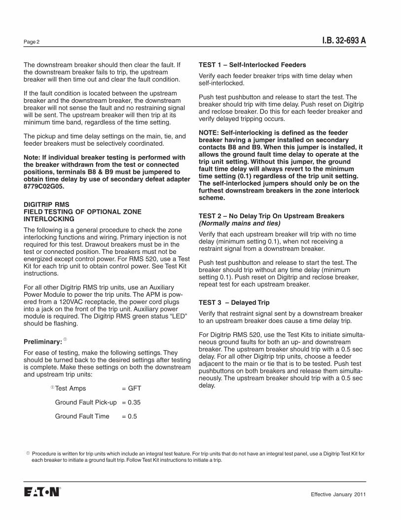
TEST 1 – Self-Interlocked Feeders
Verify each feeder breaker trips with time delay whenself-interlocked.
Push test pushbutton and release to start the test. Thebreaker should trip with time delay. Push reset on Digitripand reclose breaker. Do this for each feeder breaker andverify delayed tripping occurs.
NOTE: Self-interlocking is defined as the feederbreaker having a jumper installed on secondarycontacts B8 and B9. When this jumper is installed, itallows the ground fault time delay to operate at thetrip unit setting. Without this jumper, the groundfault time delay will always revert to the minimumtime setting (0.1) regardless of the trip unit setting.The self-interlocked jumpers should only be on thefurthest downstream breakers in the zone interlockscheme.
TEST 2 – No Delay Trip On Upstream Breakers(Normally mains and ties)
Verify that each upstream breaker will trip with no timedelay (minimum setting 0.1), when not receiving arestraint signal from a downstream breaker.
Push test pushbutton and release to start the test. Thebreaker should trip without any time delay (minimumsetting 0.1). Push reset on Digitrip and reclose breaker,repeat test for each upstream breaker.
TEST 3 – Delayed Trip
Verify that restraint signal sent by a downstream breakerto an upstream breaker does cause a time delay trip.
For Digitrip RMS 520, use the Test Kits to initiate simulta-neous ground faults for both an up- and downstreambreaker. The upstream breaker should trip with a 0.5 secdelay. For all other Digitrip trip units, choose a feederadjacent to the main or tie that is to be tested. Push testpushbuttons on both breakers and release them simulta-neously. The upstream breaker should trip with a 0.5 secdelay.
The downstream breaker should then clear the fault. Ifthe downstream breaker fails to trip, the upstreambreaker will then time out and clear the fault condition.
If the fault condition is located between the upstreambreaker and the downstream breaker, the downstreambreaker will not sense the fault and no restraining signalwill be sent. The upstream breaker will then trip at itsminimum time band, regardless of the time setting.
The pickup and time delay settings on the main, tie, andfeeder breakers must be selectively coordinated.
Note: If individual breaker testing is performed withthe breaker withdrawn from the test or connectedpositions, terminals B8 & B9 must be jumpered toobtain time delay by use of secondary defeat adapter8779C02G05.
DIGITRIP RMSFIELD TESTING OF OPTIONAL ZONEINTERLOCKING
The following is a general procedure to check the zoneinterlocking functions and wiring. Primary injection is notrequired for this test. Drawout breakers must be in thetest or connected position. The breakers must not beenergized except control power. For RMS 520, use a TestKit for each trip unit to obtain control power. See Test Kitinstructions.
For all other Digitrip RMS trip units, use an AuxiliaryPower Module to power the trip units. The APM is pow-ered from a 120VAC receptacle, the power cord plugsinto a jack on the front of the trip unit. Auxiliary powermodule is required. The Digitrip RMS green status “LED”should be flashing.
Preliminary:
For ease of testing, make the following settings. Theyshould be turned back to the desired settings after testingis complete. Make these settings on both the downstreamand upstream trip units:
Test Amps = GFT
Ground Fault Pick-up = 0.35
Ground Fault Time = 0.5
➀
Procedure is written for trip units which include an integral test feature. For trip units that do not have an integral test panel, use a Digitrip Test Kit foreach breaker to initiate a ground fault trip. Follow Test Kit instructions to initiate a trip.
➀
➀
Effective January 2011
I.B. 32-693 A Page 3
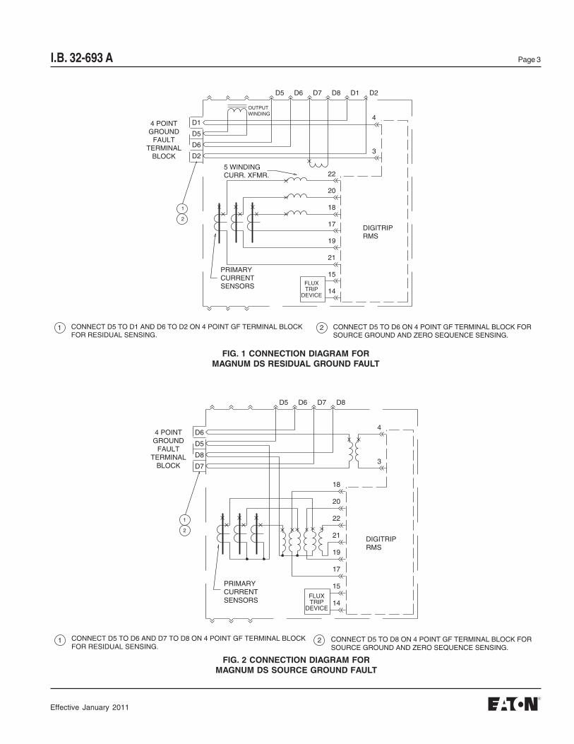
FIG. 2 CONNECTION DIAGRAM FORMAGNUM DS SOURCE GROUND FAULT
FIG. 1 CONNECTION DIAGRAM FORMAGNUM DS RESIDUAL GROUND FAULT
D5 D6 D7 D8 D1 D2
4
3
D1
D5
D6
D2
1
2
1 2CONNECT D5 TO D1 AND D6 TO D2 ON 4 POINT GF TERMINAL BLOCKFOR RESIDUAL SENSING.
CONNECT D5 TO D6 ON 4 POINT GF TERMINAL BLOCK FORSOURCE GROUND AND ZERO SEQUENCE SENSING.
DIGITRIPRMS
FLUXTRIP
DEVICE
PRIMARYCURRENTSENSORS
5 WINDINGCURR. XFMR.
OUTPUTWINDING
4 POINTGROUND
FAULTTERMINAL
BLOCK
22
20
18
17
19
21
15
14
D5 D6 D7 D8
4
3
D6
D5
D8
D7
1
2
1 2CONNECT D5 TO D6 AND D7 TO D8 ON 4 POINT GF TERMINAL BLOCKFOR RESIDUAL SENSING.
CONNECT D5 TO D8 ON 4 POINT GF TERMINAL BLOCK FORSOURCE GROUND AND ZERO SEQUENCE SENSING.
DIGITRIPRMS
FLUXTRIP
DEVICE
PRIMARYCURRENTSENSORS
4 POINTGROUND
FAULTTERMINAL
BLOCK
18
20
22
21
19
17
15
14
Effective January 2011
I.B. 32-693 APage 4
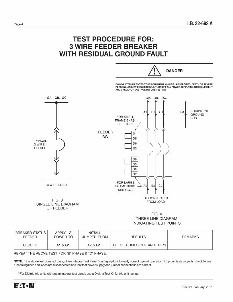
DO NOT ATTEMPT TO TEST THIS EQUIPMENT WHILE IT IS ENERGIZED. DEATH OR SEVEREPERSONAL INJURY COULD RESULT. TURN OFF ALL POWER SUPPLYING THIS EQUIPMENTAND CHECK FOR VOLTAGE BEFORE TESTING.
TEST PROCEDURE FOR:3 WIRE FEEDER BREAKER
WITH RESIDUAL GROUND FAULT
NOTE: If the above test does not pass, utilize Integral Test Panel➀ on Digitrip Unit to verify correct trip unit operation. If trip unit tests properly, check to seeif incoming lines and loads are disconnected and that test power supply and jumper connections are correct.
BREAKER STATUS APPLY 1Ø INSTALLFEEDER POWER TO JUMPER FROM RESULTS REMARKS
CLOSED A1 & G1 A2 & G1 FEEDER TIMES OUT AND TRIPS
REPEAT THE ABOVE TEST FOR “B” PHASE & “C” PHASE.
ØA, ØB, ØC,
FIG. 3SINGLE LINE DIAGRAM
OF FEEDER
TYPICAL3 WIREFEEDER
3 WIRE LOAD
ØC,
FIG. 4THREE LINE DIAGRAM
INDICATING TEST POINTS
ØB,ØA,
D1
D5
D6
D2
D6
D5
D8
D7
A1 B1 C1
A2 B2 C2
G1
FOR SMALLFRAME BKRS.
SEE FIG. 1
FOR LARGEFRAME BKRS.
SEE FIG. 2
FEEDER3W
DISCONNECTEDFROM LOAD
EQUIPMENTGROUNDBUS
DANGER
➀For Digitrip trip units without an integral test panel, use a Digitrip Test Kit for trip unit testing.
Effective January 2011

I.B. 32-693 A Page 5
TEST PROCEDURE FOR:4 WIRE FEEDER BREAKER
WITH RESIDUAL GROUND FAULT
DO NOT ATTEMPT TO TEST THIS EQUIPMENT WHILE IT IS ENERGIZED. DEATH OR SEVEREPERSONAL INJURY COULD RESULT. TURN OFF ALL POWER SUPPLYING THIS EQUIPMENTAND CHECK FOR VOLTAGE BEFORE TESTING.
NOTE: If any of the above tests do not pass, utilize ➀Integral Test Panel on Digitrip Unit to verify correct trip unit operation. If trip unit tests properly, check tosee if incoming lines and loads are disconnected and that test power supply and jumper connections are correct.
If “No Trip” test fails, reverse secondary connections at neutral sensor and repeat test. If test still fails, check that connections on breaker are per figure 1.
BREAKER STATUS APPLY 1Ø INSTALLFEEDER POWER TO JUMPER FROM RESULTS REMARKS
CLOSED A1 & N1 A2 & N2 NO TRIP POLARITY CHECK FOR NEUTRAL SENSOR
CLOSED A1 & G1 A2 & G1 FEEDER TIMES OUT AND TRIPS
REPEAT THE ABOVE TEST FOR “B” PHASE & “C” PHASE, EXCEPT NEUTRAL SENSOR POLARITY CHECK IS ONLY REQUIRED. ON ONE PHASE.
ØC,
FIG. 6THREE LINE DIAGRAM
INDICATING TEST POINTS
ØB,ØA,
D1D5D6D2
D6D5D8D7
A1 B1 C1
A2 B2 C2
G1FOR SMALL
FRAME BKRS.SEE FIG. 1
FOR LARGEFRAME BKRS.
SEE FIG. 2
FEEDER4W
N1
N
FEEDER
N2
NEUTRALSENSOR
DISCONNECTEDFROM LOAD
EQUIPMENTGROUNDBUS
ØA, ØB, ØC,
FIG. 5SINGLE LINE DIAGRAM
OF FEEDER
TYPICAL4 WIRE
FEEDER
4 WIRE LOAD
D7
( )N
( )G
D10D9C5C4C1
NEUT.
DIGITRIP
DANGER
➀For Digitrip trip units without an integral test panel, use a Digitrip Test Kit for trip unit testing.
Effective January 2011
I.B. 32-693 APage 6
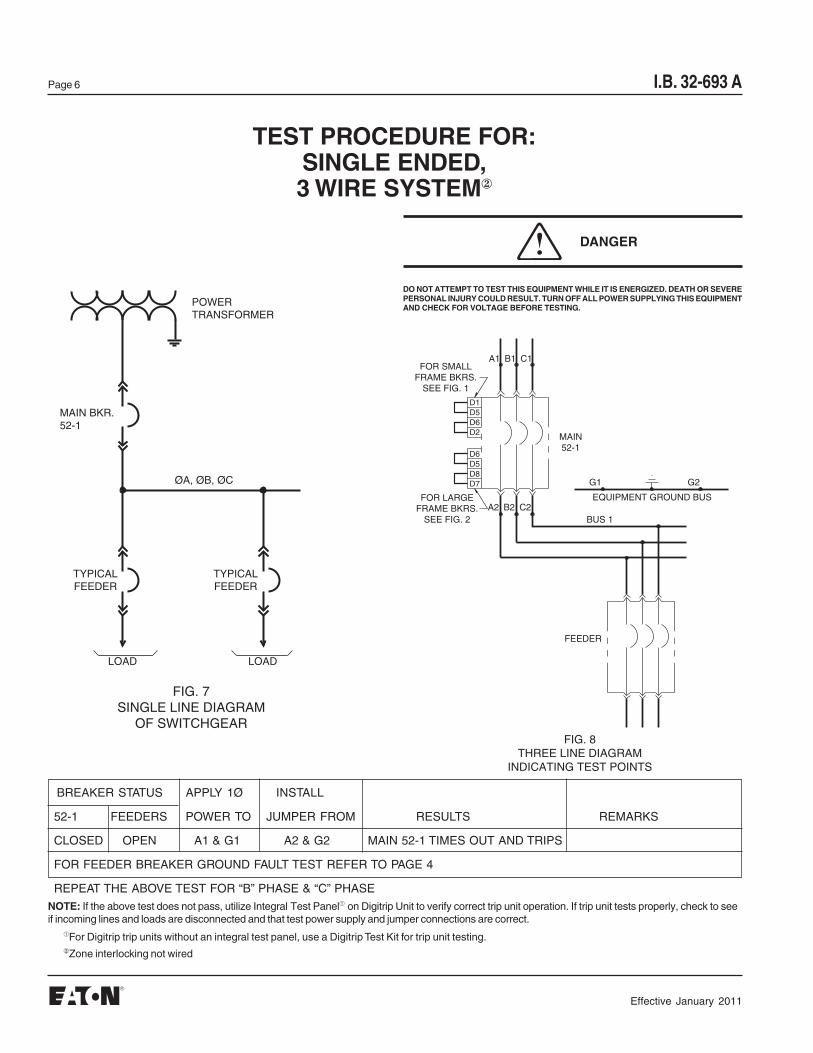
TEST PROCEDURE FOR:SINGLE ENDED,3 WIRE SYSTEM②
DO NOT ATTEMPT TO TEST THIS EQUIPMENT WHILE IT IS ENERGIZED. DEATH OR SEVEREPERSONAL INJURY COULD RESULT. TURN OFF ALL POWER SUPPLYING THIS EQUIPMENTAND CHECK FOR VOLTAGE BEFORE TESTING.
NOTE: If the above test does not pass, utilize Integral Test Panel➀ on Digitrip Unit to verify correct trip unit operation. If trip unit tests properly, check to seeif incoming lines and loads are disconnected and that test power supply and jumper connections are correct.
BREAKER STATUS APPLY 1Ø INSTALL
52-1 FEEDERS POWER TO JUMPER FROM RESULTS REMARKS
CLOSED OPEN A1 & G1 A2 & G2 MAIN 52-1 TIMES OUT AND TRIPS
FOR FEEDER BREAKER GROUND FAULT TEST REFER TO PAGE 4
REPEAT THE ABOVE TEST FOR “B” PHASE & “C” PHASE
MAIN BKR.52-1
TYPICALFEEDER
TYPICALFEEDER
LOAD LOAD
ØA, ØB, ØC
POWERTRANSFORMER
FIG. 7SINGLE LINE DIAGRAM
OF SWITCHGEARFIG. 8
THREE LINE DIAGRAMINDICATING TEST POINTS
D1D5D6D2
D6D5D8D7
A1 B1 C1
A2 B2 C2
FOR SMALLFRAME BKRS.
SEE FIG. 1
FOR LARGEFRAME BKRS.
SEE FIG. 2
MAIN52-1
G2G1
EQUIPMENT GROUND BUS
BUS 1
FEEDER
DANGER
➀For Digitrip trip units without an integral test panel, use a Digitrip Test Kit for trip unit testing.②Zone interlocking not wired
Effective January 2011
I.B. 32-693 A Page 7
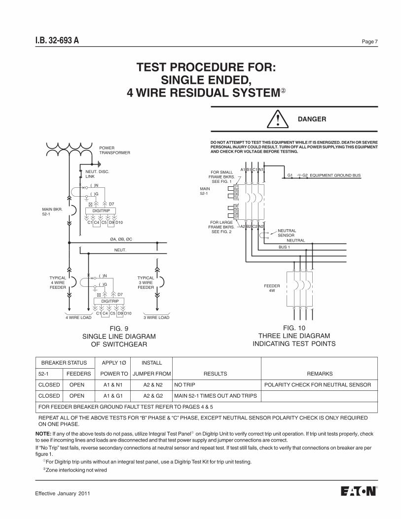
TEST PROCEDURE FOR:SINGLE ENDED,
4 WIRE RESIDUAL SYSTEM②
DO NOT ATTEMPT TO TEST THIS EQUIPMENT WHILE IT IS ENERGIZED. DEATH OR SEVEREPERSONAL INJURY COULD RESULT. TURN OFF ALL POWER SUPPLYING THIS EQUIPMENTAND CHECK FOR VOLTAGE BEFORE TESTING.
NOTE: If any of the above tests do not pass, utilize Integral Test Panel➀ on Digitrip Unit to verify correct trip unit operation. If trip unit tests properly, checkto see if incoming lines and loads are disconnected and that test power supply and jumper connections are correct.
If “No Trip” test fails, reverse secondary connections at neutral sensor and repeat test. If test still fails, check to verify that connections on breaker are perfigure 1.
BREAKER STATUS APPLY 1Ø INSTALL
52-1 FEEDERS POWER TO JUMPER FROM RESULTS REMARKS
CLOSED OPEN A1 & N1 A2 & N2 NO TRIP POLARITY CHECK FOR NEUTRAL SENSOR
CLOSED OPEN A1 & G1 A2 & G2 MAIN 52-1 TIMES OUT AND TRIPS
FOR FEEDER BREAKER GROUND FAULT TEST REFER TO PAGES 4 & 5
REPEAT ALL OF THE ABOVE TESTS FOR “B” PHASE & “C” PHASE, EXCEPT NEUTRAL SENSOR POLARITY CHECK IS ONLY REQUIREDON ONE PHASE.
MAIN BKR.52-1
DIGITRIP
DIGITRIP
TYPICAL4 WIRE
FEEDER
TYPICAL3 WIRE
FEEDER
4 WIRE LOAD 3 WIRE LOAD
NEUT.
POWERTRANSFORMER
D7
( )N
( )G
D10D9C5C4C1
( )N
( )G
D7
C1 C4 D9C5 D10
ØA, ØB, ØC
NEUT. DISC.LINK
D1D5D6D2
D6D5D8D7
A1 B1 C1
A2 B2 C2
FOR SMALLFRAME BKRS.
SEE FIG. 1
FOR LARGEFRAME BKRS.
SEE FIG. 2
MAIN52-1
G2G1 EQUIPMENT GROUND BUS
N1
N2
FEEDER4W
BUS 1
NEUTRAL
NEUTRALSENSOR
FIG. 9SINGLE LINE DIAGRAM
OF SWITCHGEAR
FIG. 10THREE LINE DIAGRAM
INDICATING TEST POINTS
DANGER
➀For Digitrip trip units without an integral test panel, use a Digitrip Test Kit for trip unit testing.②Zone interlocking not wired
Effective January 2011
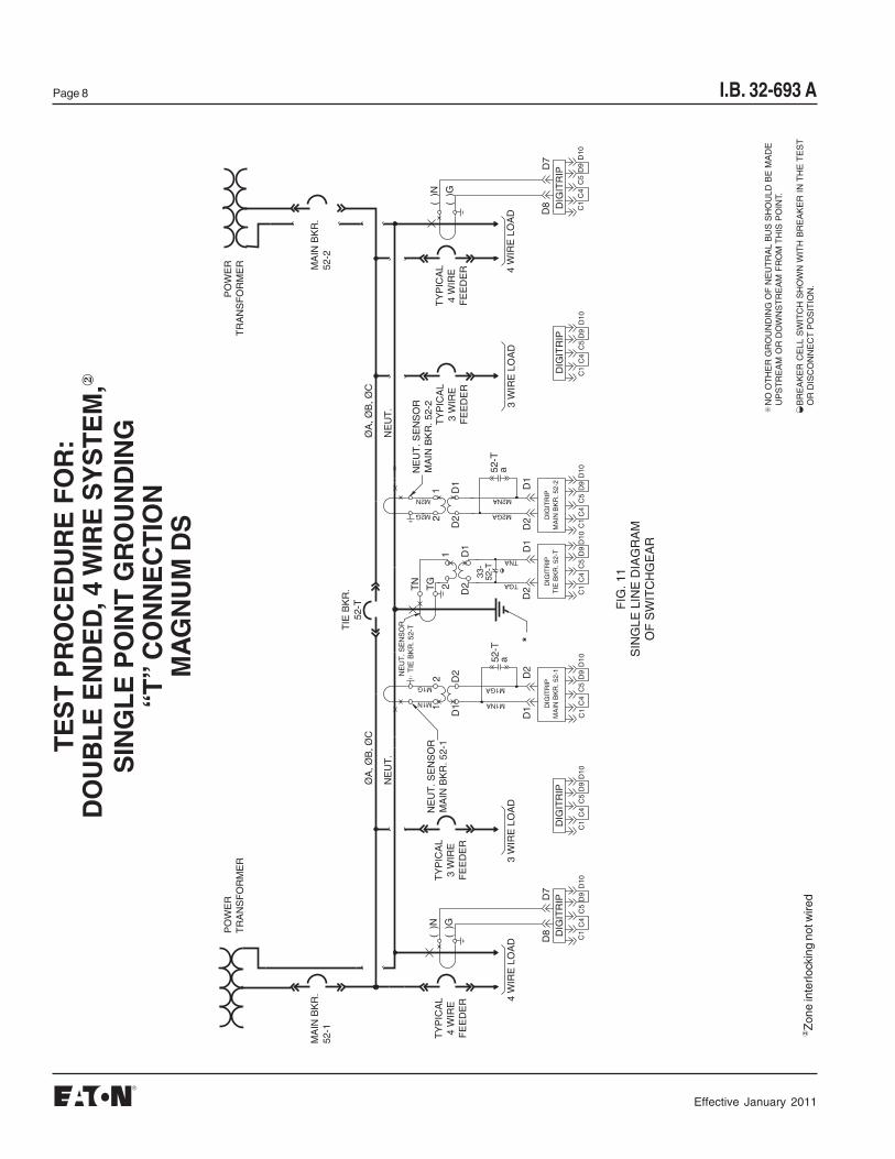
I.B. 32-693 APage 8
TE
ST
PR
OC
ED
UR
E F
OR
:D
OU
BL
E E
ND
ED
, 4 W
IRE
SY
ST
EM
,②
SIN
GL
E P
OIN
T G
RO
UN
DIN
G“T
” C
ON
NE
CT
ION
MA
GN
UM
DS
✳N
O O
TH
ER
GR
OU
ND
ING
OF
NE
UT
RA
L B
US
SH
OU
LD B
E M
AD
EU
PS
TR
EA
M O
R D
OW
NS
TR
EA
M F
RO
M T
HIS
PO
INT.
BR
EA
KE
R C
ELL
SW
ITC
H S
HO
WN
WIT
H B
RE
AK
ER
IN
TH
E T
ES
TO
R D
ISC
ON
NE
CT
PO
SIT
ION
.
◗
33-
52-T
52-T
a52
-Ta
TIE
BK
R.
52-T
NE
UT
. SE
NS
OR
MA
IN B
KR
. 52-
2
NE
UT
. SE
NS
OR
TIE
BK
R. 5
2-T
NE
UT
. SE
NS
OR
MA
IN B
KR
. 52-
1
DIG
ITR
IPM
AIN
BK
R. 5
2-2
DIG
ITR
IPT
IE B
KR
. 52-
TD
IGIT
RIP
MA
IN B
KR
. 52-
1
MA
IN B
KR
.52
-2M
AIN
BK
R.
52-1
*
DIG
ITR
IPD
IGIT
RIP
DIG
ITR
IPD
IGIT
RIP
TY
PIC
AL
4 W
IRE
FE
ED
ER
TY
PIC
AL
3 W
IRE
FE
ED
ER
4 W
IRE
LO
AD
3 W
IRE
LO
AD
3 W
IRE
LO
AD
TY
PIC
AL
3 W
IRE
FE
ED
ER
NE
UT
.
ØA
, ØB
, ØC
ØA
, ØB
, ØC
NE
UT
.
D7
( )
N
( )
G
D1
D2
D2
D1
D2
D1
PO
WE
RT
RA
NS
FO
RM
ER
PO
WE
RT
RA
NS
FO
RM
ER
C1
C4
C5
D9
D10
D10
D9
C5
C4
C1
D10
D9
C5
C4
C1
D10
D9
C5
C4
C1
C1
C4
C5
D9
D10
C1
C4
C5
D9
D10
( )
G
( )
N
D7
4 W
IRE
LO
AD
TY
PIC
AL
4 W
IRE
FE
ED
ER
D10
D9
C5
C4
C1
FIG
. 11
SIN
GLE
LIN
E D
IAG
RA
MO
F S
WIT
CH
GE
AR
D8
D8
M1NA
M1GA
TGA
TNA
M2NA
M2GA
1
D1
D2
2
D1
D2
12
D1
D22
1
M1G
M2G
M2N
TG
TN
M1N
②Z
one
inte
rlock
ing
not w
ired
Effective January 2011
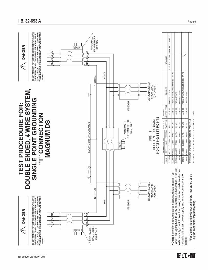
I.B. 32-693 A Page 9T
ES
T P
RO
CE
DU
RE
FO
R:
DO
UB
LE
EN
DE
D, 4
WIR
E S
YS
TE
M,
SIN
GL
E P
OIN
T G
RO
UN
DIN
G“T
” C
ON
NE
CT
ION
MA
GN
UM
DS
DA
NG
ER
DA
NG
ER
DO
NO
T A
TT
EM
PT
TO
TE
ST
TH
IS E
QU
IPM
EN
T W
HIL
E IT
ISE
NE
RG
IZE
D. D
EA
TH
OR
SE
VE
RE
PE
RS
ON
AL
INJU
RY
CO
UL
D R
ES
UL
T. T
UR
N O
FF
AL
L P
OW
ER
SU
PP
LY
ING
TH
IS E
QU
IPM
EN
T A
ND
CH
EC
K F
OR
VO
LT
AG
E B
EF
OR
ETE
STI
NG
.
DO
NO
T A
TT
EM
PT
TO
TE
ST
TH
IS E
QU
IPM
EN
T W
HIL
E IT
ISE
NE
RG
IZE
D. D
EA
TH
OR
SE
VE
RE
PE
RS
ON
AL
INJU
RY
CO
UL
D R
ES
UL
T. T
UR
N O
FF
AL
L P
OW
ER
SU
PP
LY
ING
TH
IS E
QU
IPM
EN
T A
ND
CH
EC
K F
OR
VO
LT
AG
E B
EF
OR
ETE
STI
NG
.
BR
EA
KE
R S
TA
TU
SA
PP
LY 1Ø
INS
TA
LL
52-1
52-T
52-2
FE
ED
ER
SP
OW
ER
TO
JUM
PE
R F
RO
MR
ES
ULT
SR
EM
AR
KS
CLO
SE
DO
PE
NC
LOS
ED
OP
EN
A1
& N
1A
2 &
G2
MA
IN 5
2-1
TR
IPS
IF N
O T
RIP
, CH
EC
K C
ON
N. A
T "
D5"
AN
D "
D6"
CLO
SE
DC
LOS
ED
OP
EN
OP
EN
A1
& N
1A
2 &
G2
TIE
52-
T T
RIP
S, T
HE
N M
AIN
52-
1 T
RIP
S
CLO
SE
DC
LOS
ED
OP
EN
OP
EN
A1
& N
1A
4 &
G2
TIE
52-
T T
RIP
S
CLO
SE
DO
PE
NC
LOS
ED
OP
EN
A3
& N
3A
4 &
G2
MA
IN 5
2-2
TR
IPS
OP
EN
CLO
SE
DC
LOS
ED
OP
EN
A3
& N
3A
4 &
G2
TIE
52-
T T
RIP
S, T
HE
N M
AIN
52-
2 T
RIP
S
OP
EN
CLO
SE
DC
LOS
ED
OP
EN
A3
& N
3A
2 &
G2
TIE
52-
T T
RIP
S
FO
R F
EE
DE
R B
RE
AK
ER
TE
ST
RE
FE
R T
O P
AG
ES
4 &
5
RE
PE
AT
ALL
OF
TH
E A
BO
VE
TE
ST
S F
OR
“B
” P
HA
SE
& “
C”
PH
AS
E
NO
TE
: If a
ny o
f the
abo
ve te
sts
do n
ot p
ass,
util
ize
Inte
gral
Tes
tP
anel
➀ o
n D
igitr
ip U
nit
to v
erify
cor
rect
trip
uni
t ope
ratio
n. If
trip
uni
tte
sts
prop
erly
, che
ck to
see
if in
com
ing
lines
and
load
s ar
e di
scon
-ne
cted
and
that
test
pow
er s
uppl
y an
d ju
mpe
r con
nect
ions
are
corr
ect.
FIG
. 12
TH
RE
E L
INE
DIA
GR
AM
IND
ICA
TIN
G T
ES
T P
OIN
TS
D1
D5
D6
D2
A1
B1
C1
A2
B2
C2
FO
R S
MA
LLF
RA
ME
BK
RS
.S
EE
FIG
. 1
G2
G1
EQ
UIP
ME
NT
GR
OU
ND
BU
S
N1
N2
FE
ED
ER
BU
S 1N
EU
TR
AL
D2D6D5D1
DIS
CO
NN
EC
TE
DF
RO
M L
OA
D(O
R O
PE
N)
FO
R S
MA
LLF
RA
ME
BK
RS
.S
EE
FIG
. 1
DIS
CO
NN
EC
TE
DF
RO
M L
OA
D(O
R O
PE
N)
FE
ED
ER
BU
S 2
N3
N4
FO
R S
MA
LLF
RA
ME
BK
RS
.S
EE
FIG
. 1
B4
A4
C4
D2
D6D1
D5
B3
A3
C3
NE
UT
RA
L
➀Fo
r Dig
itrip
trip
uni
ts w
ithou
t an
inte
gral
test
pan
el, u
se a
Dig
itrip
Tes
t Kit
for t
rip u
nit t
estin
g.
Effective January 2011

I.B. 32-693 APage 10
TE
ST
PR
OC
ED
UR
E F
OR
:D
OU
BL
E E
ND
ED
, 4 W
IRE
SY
ST
EM
,M
OD
IFIE
D R
ES
IDU
AL
GR
OU
ND
FA
ULT
MA
IN A
ND
TIE
BR
EA
KE
RS
MU
ST
HA
VE
TH
E S
AM
E F
RA
ME
AN
D S
EN
SO
R R
ATIN
GS
, AN
D O
NE
OF
TH
E T
HR
EE
MU
ST
BE
NO
RM
ALL
Y O
PE
N.
NO
OT
HE
R G
RO
UN
DIN
G O
F N
EU
TR
AL
BU
S S
HO
ULD
BE
MA
DE
DO
WN
ST
RE
AM
FR
OM
TH
ES
E T
WO
PO
INT
S. T
O D
O S
O W
ILL
DE
FE
AT T
HE
GR
OU
ND
FA
ULT
PR
OT
EC
TIO
N.
▲
✳■
PO
LAR
ITY
MU
ST
BE
AS
SH
OW
N.
TIE
BK
R.
52-T
NE
UT
. SE
NS
OR
MA
IN B
KR
. 52-
2
NE
UT
. SE
NS
OR
TIE
BK
R. 5
2-T
NE
UT
. SE
NS
OR
MA
IN B
KR
. 52-
1
DIG
ITR
IPM
AIN
BK
R. 5
2-2
DIG
ITR
IPT
IE B
KR
. 52-
TD
IGIT
RIP
MA
IN B
KR
. 52-
1
MA
IN B
KR
.52
-2M
AIN
BK
R.
52-1
**
DIG
ITR
IPD
IGIT
RIP
DIG
ITR
IPD
IGIT
RIP
52-1 a
52-T a
52-2 a
NE
UT
.
ØA
, ØB
, ØC
ØA
, ØB
, ØC
NE
UT
.
D7
D7
D7
PO
WE
RT
RA
NS
FO
RM
ER
PO
WE
RT
RA
NS
FO
RM
ER
( )
G
( )
N
D7
3 W
IRE
LO
AD
4 W
IRE
LO
AD
TY
PIC
AL
3 W
IRE
FE
ED
ER
TY
PIC
AL
4 W
IRE
FE
ED
ER
TY
PIC
AL
4 W
IRE
FE
ED
ER 4
WIR
E L
OA
D
D7
( )
N
( )
G
TY
PIC
AL
3 W
IRE
FE
ED
ER
3 W
IRE
LO
AD
C1
C4
C5
C5
C4
C1
C5
C4
C1
C1
C4
C5
C1
C4
C5
C1
C4
C5
D10
D9
C5
C4
C1
FIG
. 15
SIN
GLE
LIN
E D
IAG
RA
MO
F S
WIT
CH
GE
AR
MN
M1G
M2G
MN
MN
MN
M1G
M2G
M1GA
M2GA
TG
▲
■
■
▲
■
▲
②Z
one
inte
rlock
ing
not w
ired
Effective January 2011
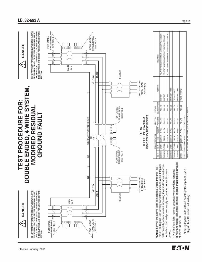
I.B. 32-693 A Page 11T
ES
T P
RO
CE
DU
RE
FO
R:
DO
UB
LE
EN
DE
D, 4
WIR
E S
YS
TE
M,
MO
DIF
IED
RE
SID
UA
LG
RO
UN
D F
AU
LT
DA
NG
ER
DO
NO
T A
TT
EM
PT
TO
TE
ST
TH
IS E
QU
IPM
EN
T W
HIL
E IT
ISE
NE
RG
IZE
D. D
EA
TH
OR
SE
VE
RE
PE
RS
ON
AL
INJU
RY
CO
UL
D R
ES
UL
T. T
UR
N O
FF
AL
L P
OW
ER
SU
PP
LY
ING
TH
IS E
QU
IPM
EN
T A
ND
CH
EC
K F
OR
VO
LT
AG
E B
EF
OR
ETE
STI
NG
.
DO
NO
T A
TT
EM
PT
TO
TE
ST
TH
IS E
QU
IPM
EN
T W
HIL
E IT
ISE
NE
RG
IZE
D. D
EA
TH
OR
SE
VE
RE
PE
RS
ON
AL
INJU
RY
CO
UL
D R
ES
UL
T. T
UR
N O
FF
AL
L P
OW
ER
SU
PP
LY
ING
TH
IS E
QU
IPM
EN
T A
ND
CH
EC
K F
OR
VO
LT
AG
E B
EF
OR
ETE
STI
NG
.
NO
TE
: If a
ny o
f the
abo
ve te
sts
do n
ot p
ass,
util
ize
Inte
gral
Tes
tP
anel
➀ o
n D
igitr
ip U
nit t
o ve
rify
corr
ect t
rip u
nit o
pera
tion.
If tr
ip u
nit
test
s pr
oper
ly, c
heck
to s
ee if
inco
min
g lin
es a
nd lo
ads
are
disc
on-
nect
ed a
nd th
at te
st p
ower
sup
ply
and
jum
per c
onne
ctio
ns a
reco
rrec
t.
If “N
o T
rip” t
est f
ails
, rev
erse
sec
onda
ry c
onne
ctio
ns a
t neu
tral
sens
or a
nd re
peat
test
. If t
est s
till f
ails
, che
ck c
onne
ctio
ns to
Bre
aker
at p
oint
s B
4 th
ru B
9.
BR
EA
KE
R S
TA
TU
SA
PP
LY 1Ø
INS
TA
LL
52-1
52-T
52-2
FE
ED
ER
SP
OW
ER
TO
JUM
PE
R F
RO
MR
ES
ULT
SR
EM
AR
KS
CLO
SE
DO
PE
NC
LOS
ED
OP
EN
A1
& N
1A
2 &
N2
NO
TR
IPP
OLA
RIT
Y C
HE
CK
FO
R M
AIN
52-
1 N
EU
TR
AL
SE
NS
OR
CLO
SE
DC
LOS
ED
OP
EN
OP
EN
A1
& N
1A
4 &
N4
NO
TR
IPP
OLA
RIT
Y C
HE
CK
FO
R T
IE 5
1-T
NE
UT
RA
L S
EN
SO
R
CLO
SE
DO
PE
NC
LOS
ED
OP
EN
A3
& N
3A
4 &
N4
NO
TR
IPP
OLA
RIT
Y C
HE
CK
FO
R M
AIN
52-
2 N
EU
TR
AL
SE
NS
OR
CLO
SE
DO
PE
NC
LOS
ED
OP
EN
A1
& N
1A
2 &
G2
MA
IN 5
2-1
TR
IPS
CLO
SE
DC
LOS
ED
OP
EN
OP
EN
A1
& N
1A
4 &
G2
TIE
52-
T T
RIP
S
CLO
SE
DO
PE
NC
LOS
ED
OP
EN
A3
& N
3A
4 &
G2
MA
IN 5
2-2
TR
IPS
OP
EN
CLO
SE
DC
LOS
ED
OP
EN
A3
& N
3A
2 &
G2
TIE
52-
T T
RIP
S
FO
R F
EE
DE
R B
RE
AK
ER
TE
ST
RE
FE
R T
O P
AG
ES
4 &
5
RE
PE
AT
ALL
OF
TH
E A
BO
VE
TE
ST
S F
OR
“B
” P
HA
SE
& “
C”
PH
AS
E
FIG
. 16
TH
RE
E L
INE
DIA
GR
AM
IND
ICA
TIN
G T
ES
T P
OIN
TS
D6
D5
D8
D7
A1
B1
C1
A2
B2
C2
FO
R L
AR
GE
FR
AM
E B
KR
S.
SE
E F
IG. 2
G2
G1
EQ
UIP
ME
NT
GR
OU
ND
BU
S
N1
N2
FE
ED
ER
BU
S 1N
EU
TR
AL
D7D8D5D6
DIS
CO
NN
EC
TE
DF
RO
M L
OA
D(O
R O
PE
N)
FO
R L
AR
GE
FR
AM
E B
KR
S.
SE
E F
IG. 2
DIS
CO
NN
EC
TE
DF
RO
M L
OA
D(O
R O
PE
N)
FE
ED
ER
BU
S 2
N4
N5
FO
R L
AR
GE
FR
AM
E B
KR
S.
SE
E F
IG. 2
B5
A5
C5
D7
D8
D6
D5
B4
A4
C4
NE
UT
RA
L
FO
R S
MA
LLF
RA
ME
BK
RS
.S
EE
FIG
. 1 D1
D5
D6
D2
MA
IN52
-1
FO
R S
MA
LLF
RA
ME
BK
RS
.S
EE
FIG
. 1D5D6D2
D1
TIE
52-T
MA
IN52
-2D
2D
6D
5D
1FO
R S
MA
LLF
RA
ME
BK
RS
.S
EE
FIG
. 1
DA
NG
ER
➀Fo
r Dig
itrip
trip
uni
ts w
ithou
t an
inte
gral
test
pan
el, u
se a
Dig
itrip
Tes
t Kit
for t
rip u
nit t
estin
g.
Effective January 2011

I.B. 32-693 APage 12
GROUND FAULT TEST RECORD FORM
TEST DATE CIRCUIT BREAKER NO. RESULTS TESTED BY
Ground Fault Test Record should be retained by those in charge of the building’s Electrical Installation in order to beavailable to the authority having jurisdiction.
Effective January 2011

I.B. 32-693 A Page 13
GROUND FAULT TEST RECORD FORM
TEST DATE CIRCUIT BREAKER NO. RESULTS TESTED BY
Ground Fault Test Record should be retained by those in charge of the building’s Electrical Installation in order to beavailable to the authority having jurisdiction.
Effective January 2011

I.B. 32-693 APage 14
Effective January 2011

I.B. 32-693 A Page 15
Effective January 2011

Page 16 I.B. 32-693 A
This instruction booklet is published solely for information purposes and should not be considered all inclusive. Iffurther information is required, you should consult E .
Sale of product shown in this literature is subject to terms and conditions outlined in appropriate Eaton selling policies or other contractual agreement between the parties. This literature is not intended to and does notenlarge or add to any such contract. The sole source governing the rights and remedies of any purchaser of thisequipment is the contract between the purchaser and
NO WARRANTIES, EXPRESSED OR IMPLIED, INCLUDING WARRANTIES OF FITNESS FOR A PARTICULARPURPOSE OR MERCHANTABILITY, OR WARRANTIES ARISING FROM COURSE OF DEALING OR USAGE OFTRADE, ARE MADE REGARDING THE INFORMATION, RECOMMENDATIONS AND DESCRIPTIONS CON-TAINED HEREIN. In no event will be responsible to the purchaser or user in contract, in tort (includ-ing negligence), strict liability or otherwise for any special, indirect, incidental or consequential damage or loss what-soever, including but not limited to damage or loss of use of equipment, plant or power system, cost of capital, loss ofpower, additional expenses in the use of existing power facilities, or claims against the purchase or user by its cus-tomers resulting from the use of the information, recommendations and descriptions contained herein.
221 Heywood RoadArden, NC 28704
Effective January 20Printed in U.S.A./CCI
11
aton
Eaton.
Eaton