Embed Size (px)
Citation preview
1
Instructions for the SOH Lab CNC Mill and the dxf2fgc
Conversion Program
Will Grover Mathies Group, UC Berkeley
May 24, 2004
Revised and Updated by for UCSB Soh Lab by UCSB Capstone Team 19,2012
1 Introduction If you're reading this to learn how to use the lab's mill and you don't much care about what is happening
behind the scenes, skip ahead to the section entitled “Operation.” This document1 was prepared to be
applicable to dxf2fgc v1.20, LabVIEW v5.1, and FlashCut v1.61.
1.1 Theory of operation Our application requires precise drilling of holes relative to features etched into glass wafers. There are two
main approaches to solving this alignment problem: Carefully align the etched wafer to the mill so that holes are drilled exactly in the locations specified by the
CAD file, or Arbitrarily place the etched wafer on the mill and use a camera to determine the location of the wafer
relative to the mill's xed coordinates, then use this information to offset (rotate and translate) the hole
coordinates in the CAD file so that the holes are drilled in the correct places on the otherwise arbitrarily-
placed wafer. The first method is suitable when the parts for drilling have features like edges or corners that cut into “jigs”; the
resulting holes will be located accurately relative to the alignment features. Unfortunately, since the etched
features in our wafers are usually not aligned to the wafer itself with any great precision, and since our wafers are
round, placing the etched wafer in a “jig” for drilling does not adequately x the location or the angle of rotation of
the wafer's features relative to the mill. The second method of alignment (our chosen method) deemphasizes precise place-ment of the wafer in favor
of careful measurement of the locations of two alignment marks on the wafer. The process of converting a
DXF file (containing circles at the locations of the holes to drill) to a FGC file (encoding all the mill motions
necessary for drilling the wafers) may be summarized as follows: 1
Please send any suggestions or corrections to [email protected]
2
1. By using the drill bit to nick the surface of the wafer in an empty region, the height of the wafer surface
in the Z -dimension of the mill's internal coordinate system is determined. 2. By sighting the nick in the camera, the offset between the drill bit and the camera crosshair in the XY
plane of the mill's internal coordinate system is determined. 3. By using the camera to sight the locations of two alignment marks on the wafer, the locations of these
two marks in the XY plane of the mill's internal coordinate system are determined. 4. The operator provides the locations of the alignment marks in the XY plane of the DXF file's coordinate
system. 5. Using the two sets of coordinates for the alignment marks (one set relative to the mill/wafer system and
the other relative to the DXF system), a two-part off-set (rotation and translation) between the DXF
alignments and the mill/wafer alignments is calculated. 6. This offset is applied to the coordinates of each hole to be drilled in the DXF file, thereby converting their
locations to the mill/wafer coordinate system. 7. The XY locations of the holes in the mill/wafer coordinate system are converted to “G code” instructions
and combined with operations in the Z dimension that encode the “pecking” motions necessary for
drilling glass. The resulting FGC file is saved for use by the mill's FlashCut software.
2 Operation 2.1 Wafer preparation Attach your wafer to a blank backing wafer with pine resin according to our usual drilling protocol
2. Scrape
excess pine resin off the back of the backing wafer to improve the seal on the mill's vacuum chuck.
2.2 Preparation of DXF file(s) The locations of circles in your DXF file(s) are used to determine where to drill holes in your wafer. The radius,
layer, and other parameters of the circles are irrelevant to the conversion program–all circles present in a given
DXF file will be drilled; other 2
Place a blank backing wafer on an aluminum foil-covered hotplate and sprinkle ground pine resin over the wafer's surface. When the resin has
melted place the etched wafer on the backing wafer and gently press the bubbles out of the trapped layer of pine resin. I prefer to place the
wafer with etched features facing up so that the etched features and the drilled nick will both lie in the same focal plane and will be easy to
sight accurately with the camera. Lift the wafers off the hotplate with the aluminum foil and continue to press the wafers together as the
resin cools. Any bubbles remaining at the locations of drilled holes may cause wafer breakage when those holes are drilled.

3
shapes like lines or polylines will be ignored. Remember to remove any big circles representing the outline of your
wafer (unless you want a hole drilled in the center of your wafer!). If you use AutoCAD for designing masks,
run a purge command to eliminate any empty blocks, layers, etc. (they confuse the dxf2fgc program)3.
Export your mask as DXF files (any of the DXF formats will work) and save them to a oppy. You should
have one DXF file for each drill bit that you plan to use, containing only the circles/holes that you plan to
drill with that bit. For example, say you have a wafer with 100 large holes and 40 small holes. If you
want to drill 50 large holes per bit (using two large bits in the process) and 40 small holes per bit (using
only one small bit in the process), you'll need a total of 3 DXF files with names and contents something
like this: 1. bigbit1.dxf includes circles at locations of first 50 big holes 2. bigbit2.dxf includes circles at locations of remaining 50 big holes 3. smlbit1.dxf includes circles at locations of all 40 small holes This may sound like a lot of work but you only have to generate these DXF files once for a given mask and
drilling regime. The dxf2fgc program will accept DXF files with a scale of either 1 mm/unit or 1 m/unit. Try to limit the filenames to the traditional DOS “8.3”
limits (eight character filename plus .DXF) because the FlashCut program is unable to read longer
filenames. You'll also need to know the DXF file coordinates of two alignment marks from your wafer. For greatest
alignment accuracy, the two alignment marks should be as far apart as possible, ideally straight across from
each other (left to right across the wafer), and should be clearly visible on the etched wafer. Using a Sharpie
pen to draw a circle around tiny alignment marks will you nd the marks under the camera. Circles for
drilling can be used as one or both of the alignment marks, but it can be dif cult to align to large circles.
2.3 Starting the CNC mill 1. Check your email to make sure that no mill-related problems have been reported. See the Notes section
for more details. 2. Turn on the two power supply/controller boxes lying behind the CNC mill. Turn on the computer if it isn't
already on. The electrical connection between the computer and the LCD screen is shaky and if the screen
freezes or turns white, bend the screen back and forth until the screen works again. 3. Run the program FlashCut CNC (shortcut on the desktop). When asked whether the program should establish a
connection to the signal generator, click Yes, then click Agree, then click Yes when asked whether to run backlash
compensation.
4. Check the breadboard around the CNC mill and make sure nothing is obstructing the path of the mill.
The screen should look like Figure 1. 3
If you don't use AutoCAD, read the Notes section for information about writing your own DXF file from scratch.
4
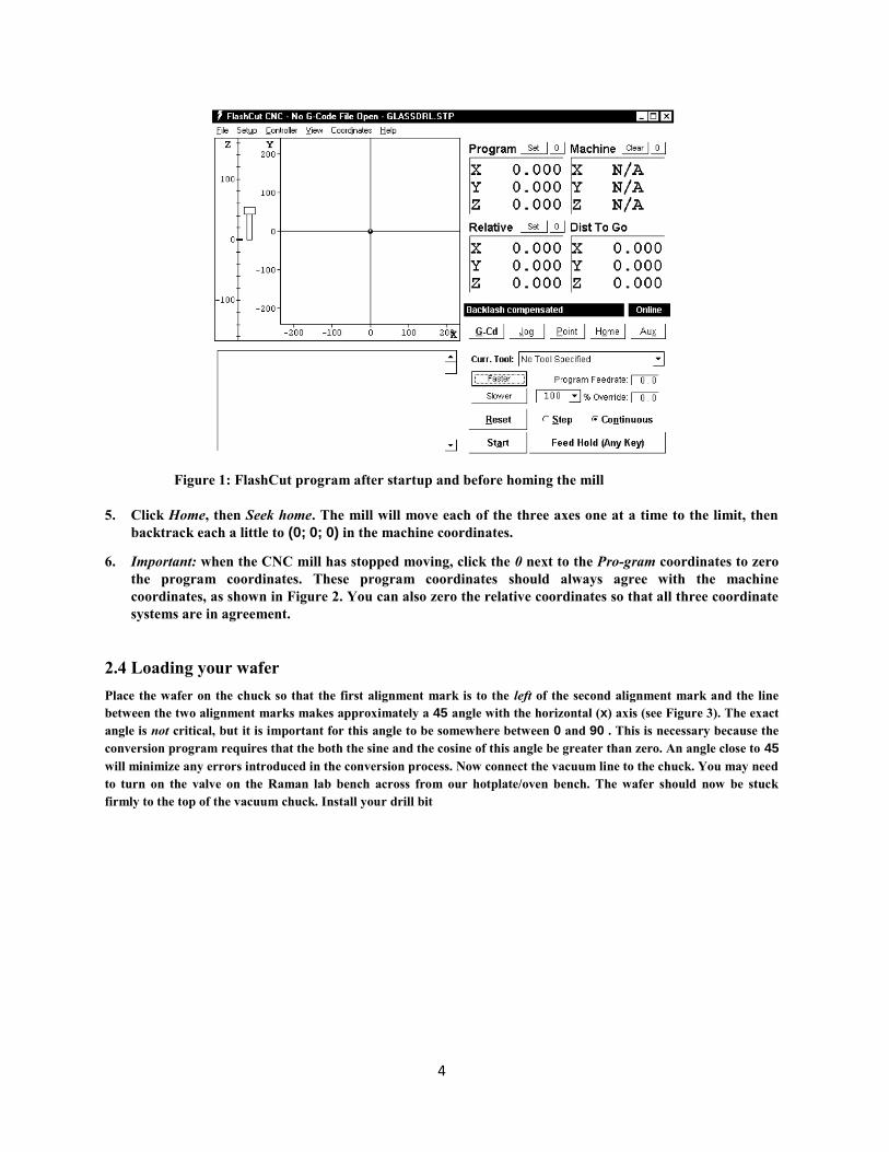
Figure 1: FlashCut program after startup and before homing the mill
5. Click Home, then Seek home. The mill will move each of the three axes one at a time to the limit, then
backtrack each a little to (0; 0; 0) in the machine coordinates. 6. Important: when the CNC mill has stopped moving, click the 0 next to the Pro-gram coordinates to zero
the program coordinates. These program coordinates should always agree with the machine
coordinates, as shown in Figure 2. You can also zero the relative coordinates so that all three coordinate
systems are in agreement.
2.4 Loading your wafer Place the wafer on the chuck so that the first alignment mark is to the left of the second alignment mark and the line
between the two alignment marks makes approximately a 45 angle with the horizontal (x) axis (see Figure 3). The exact
angle is not critical, but it is important for this angle to be somewhere between 0 and 90 . This is necessary because the
conversion program requires that the both the sine and the cosine of this angle be greater than zero. An angle close to 45
will minimize any errors introduced in the conversion process. Now connect the vacuum line to the chuck. You may need
to turn on the valve on the Raman lab bench across from our hotplate/oven bench. The wafer should now be stuck
firmly to the top of the vacuum chuck. Install your drill bit

5
Figure 2: FlashCut program after seeking home and zeroing Program and Relative coordinates
in the chuck and make sure the bit is centered in the chuck by watching the bit while rotating the chuck by
hand.
2.5a Converting your DXF file for a circular wafer using alignment marks. Start the dxf2fgc program and select the circular wafer with alignment marks tab, as shown in Figure 4.
Converting your first DXF file takes longer than the remaining files because some a number of
alignment steps must be performed. On subsequent DXF conversions (for subsequent drill bits) only a
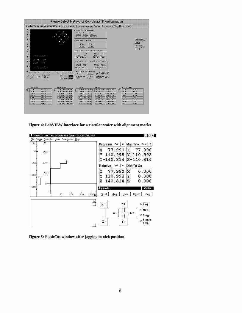
single parameter must be adjusted; see Converting subsequent DXF files 1. Important: notice that when the mill is in the home position, the vacuum chuck is very close to the pillar that
supports the Z axis. When the mill is in this position, first move the chuck out (+y) clear of the pillar before moving the chuck left (+x). Clicking +x when the mill is homed will drive the chuck into the pillar and damage the mill! So...
2. Using the jog controls in the FlashCut program as shown in Figure 5, use (+y) first, then use the
remaining jog controls to position the drill bit near the surface of the wafer in a region that can be
nicked without hurting the final device. Place a drop or two of milling fluid on the wafer beneath the bit.
6
Figure 4: LabVIEW interface for a circular wafer with alignment marks
Figure 5: FlashCut window after jogging to nick position
7
3. Turn on the drill motor switch and gently ramp the speed up to the highest set-ting. Using single mouse-
clicks on the medium speed, slowly bring the bit down until it enters the fluid drop and just touches the
surface of the wafer (a tiny plume of glass milk will be seen when the rotating bit contacts the wafer
surface). Immediately turn down the drill speed and turn off the drill, and transfer the current (x; y; z)
coordinates to Box 1 (“Coordinates of nick when drilled”) on the dxf2fgc program. Carefully jog the Z
axis in the positive direction (up) clear of the wafer before proceeding.
4. Use the Jog controls in the FlashCut program to move the drilled nick to the crosshair of the camera. You
might want to use the center point (1.5) of the 3.0-unit ruler as the crosshair. Adjust the focus and
position of the camera as necessary, but after this step the position and focus of the camera should be left unchanged. The camera
should be placed as close as is safely possible to the pulley and drilling head mounted on the Z axis.
When the nick is centered on the crosshair, transfer the (x; y) coordinates to Box 2 (“Coordinates of
nick in crosshair”) on the dxf2fgc program, and be careful not to bump, change the focus of, or otherwise
disturb the camera from this point on! 5. Fill in the DXF file coordinates of the two alignment marks in Box 3 (“Coordinates of alignment marks
from CAD file”) on the dxf2fgc program. These are the coordinates of the two alignment marks as read
directly from your original CAD file. 6. Use the Jog controls to move the first alignment mark to the crosshair of the camera. Transfer the (x; y) coordinates to Box 4 (“Coordinates of alignment marks in camera
crosshair”) on the dxf2fgc program. Now use the Jog controls to move the second alignment point to the
crosshair of the camera and transfer these (x; y) coordinates to Box 4 as well. 7. Set the remaining controls on the dxf2fgc program to your desired values. Set the Input file units switch to
either “mm” or “ m” depending upon the units of your input DXF file. Specify the thickness of the wafer you
are drilling. The overdrill is the distance drilled on each hole past the top wafer and into the backing wafer.
Naturally this distance should be more than 0 (to guarantee that the top wafer has been drilled completely)
but less than the thickness of the backing wafer. A typical value of 200 m should be increased to 400 or 500 m
for runs requiring a large number of holes to be drilled with a single bit. Currently we are drilling 0.1 mm per
peck with a feed rate of 5 mm/min during drilling and an overdrill of 200 to 500 m. 8. When all values on the dxf2fgc program are correct, run the program by clicking the arrow button in the upper-left
corner of the screen. The program will ask for the location of the DXF file you're converting; specify the first DXF
file you plan to drill. The program will then ask you to name the output FGC file; assign a name that associates the
FGC file with the source DXF file. The program will also plot both the original DXF coordinates (open circles) and
the new machine-based coordinates (filled circles) for the holes to be drilled. Make sure that the angle of rotation of
the machine holes on the screen resembles the actual angle of rotation of your wafer. You may even want to use the
Jog controls on the Flash-Cut program to move the bit to the location of a hole on the wafer and check the (x; y)
coordinates of this point against the approximate coordinates for the hole read from the plot on the dxf2fgc
program.
9. IMPORTANT – when you're done, don't close the convert program. If you have additional DXF files to
convert later, you'll reuse most of the values you entered. If you close the program those values will be
lost!
2.5b Converting your DXF file for a circular wafer that is referenced to the approximate
center of the wafer
A new feature added to the UCSB system allows you to begin drilling without having to use alignment

8
marks. Please only use this method if there are no pre-existing features located on your circular wafer.
This method uses the assumption that the center of the vacuum chuck is fixed, so the mill skips the need
for alignment marks and jogs straight to the approximate center of the wafer and begins to drill. See
section 2.4 for loading your wafer and try to center the wafer as close as possible by inspection. Select
the circular wafer from approximate center tab on DXF2FGC.
1. Important: notice that when the mill is in the home position, the vacuum chuck is very close to the pillar
that supports the Z axis. When the mill is in this position, first move the chuck out (+y) clear of the pillar
before moving the chuck left (+x). Clicking +x when the mill is homed will drive the chuck into the pillar
and damage the mill! So... 2. Using the jog controls in the FlashCut program as shown in Figure 5, use (+y) first, then use the
remaining jog controls to position the drill bit near the surface of the wafer in a region that can be
nicked without hurting the final device. Place a drop or two of milling fluid on the wafer beneath the bit.
3. Turn on the drill motor switch and gently ramp the speed up to the highest setting. Using single mouse-
clicks on the medium speed, slowly bring the bit down until it enters the fluid drop and just touches the
surface of the wafer (a tiny plume of glass milk will be seen when the rotating bit contacts the wafer
surface). Immediately turn down the drill speed and turn off the drill, and transfer the current z
coordinates to Box 1 (“Coordinates of nick when drilled”) on the dxf2fgc program. Carefully jog the Z
axis in the positive direction (up) clear of the wafer before proceeding.
4. When all values on the dxf2fgc program are correct, run the program by clicking the arrow button in
the upper-left corner of the screen. The program will ask for the location of the DXF file you're
converting; specify the first DXF file you plan to drill. The program will then ask you to name the
output FGC file; assign a name that associates the FGC file with the source DXF file. The program will
also plot both the original DXF coordinates (open circles) and the new machine-based coordinates (filled
circles) for the holes to be drilled. Make sure that the angle of rotation of the machine holes on the
screen resembles the actual angle of rotation of your wafer. You may even want to use the Jog controls
on the Flash-Cut program to move the bit to the location of a hole on the wafer and check the (x; y)
coordinates of this point against the approximate coordinates for the hole read from the plot on the
dxf2fgc program.
5. IMPORTANT – when you're done, don't close the convert program. If you have additional DXF files to
convert later, you'll reuse most of the values you entered. If you close the program those values will be
lost!
See section 4.1 for resetting the center of the vacuum chuck
2.5c Converting your DXF file for a rectangular microscope sliding using the corners as
alignment marks. Start the dxf2fgc program and select the rectangular slide tab, as shown in Figure 4. Converting your
first DXF file takes longer than the remaining files because some a number of alignment steps must be
performed. On subsequent DXF conversions (for subsequent drill bits) only a single parameter must be
adjusted; see Converting subsequent DXF files
9
1. Important: notice that when the mill is in the home position, the vacuum chuck is very close to the pillar that
supports the Z axis. When the mill is in this position, first move the chuck out (+y) clear of the pillar before moving the chuck left (+x). Clicking +x when the mill is homed will drive the chuck into the pillar and damage the mill! So...
2. Using the jog controls in the FlashCut program as shown in Figure 5, use (+y) first, then use the
remaining jog controls to position the drill bit near the surface of the wafer in a region that can be
nicked without hurting the final device. Place a drop or two of milling fluid on the wafer beneath the bit.
3. Turn on the drill motor switch and gently ramp the speed up to the highest set-ting. Using single mouse-
clicks on the medium speed, slowly bring the bit down until it enters the fluid drop and just touches the
surface of the wafer (a tiny plume of glass milk will be seen when the rotating bit contacts the wafer
surface). Immediately turn down the drill speed and turn off the drill, and transfer the current (x; y; z)
coordinates to Box 1 (“Coordinates of nick when drilled”) on the dxf2fgc program. Carefully jog the Z
axis in the positive direction (up) clear of the wafer before proceeding.
4. Use the Jog controls in the FlashCut program to move the drilled nick to the crosshair of the camera.
You might want to use the center point (1.5) of the 3.0-unit ruler as the crosshair. Adjust the focus and
position of the camera as necessary, but after this step the position and focus of the camera should be left
unchanged. The camera should be placed as close as is safely possible to the pulley and drilling head
mounted on the Z axis. When the nick is centered on the crosshair, transfer the (x; y) coordinates to Box
2 (“Coordinates of nick in crosshair”) on the dxf2fgc program, and be careful not to bump, change the
focus of, or otherwise disturb the camera from this point on!
5. Fill in the DXF file coordinates of the two corners in Box 3 (“Coordinates of alignment marks from
CAD file”) on the dxf2fgc program. These are the coordinates of the corners as read directly from your
original CAD file.
6. Use the Jog controls to move the first corner to the crosshair of the
camera. Transfer the (x; y) coordinates to Box 4 (“Coordinates of corners camera crosshair”) on the
dxf2fgc program. Now use the Jog controls to move the second corner to the crosshair of the camera and
transfer these (x; y) coordinates to Box 4 as well.
7. Set the remaining controls on the dxf2fgc program to your desired values. Set the Input file units switch
to either “mm” or “ m” depending upon the units of your input DXF file. Specify the thickness of the
wafer you are drilling. The overdrill is the distance drilled on each hole past the top wafer and into the
backing wafer. Naturally this distance should be more than 0 (to guarantee that the top wafer has been
drilled completely) but less than the thickness of the backing wafer. A typical value of 200 m should be
increased to 400 or 500 m for runs requiring a large number of holes to be drilled with a single bit.
Currently we are drilling 0.1 mm per peck with a feed rate of 5 mm/min during drilling and an overdrill
of 200 to 500 m.
8. When all values on the dxf2fgc program are correct, run the program by clicking the arrow button in the
upper-left corner of the screen. The program will ask for the location of the DXF file you're converting;
specify the first DXF file you plan to drill. The program will then ask you to name the output FGC file;
assign a name that associates the FGC file with the source DXF file. The program will also plot both the
original DXF coordinates (open circles) and the new machine-based coordinates (filled circles) for the
holes to be drilled. Make sure that the angle of rotation of the machine holes on the screen resembles the
actual angle of rotation of your wafer. You may even want to use the Jog controls on the Flash-Cut
program to move the bit to the location of a hole on the wafer and check the (x; y) coordinates of this
point against the approximate coordinates for the hole read from the plot on the dxf2fgc program.
9. IMPORTANT – when you're done, don't close the convert program. If you have additional DXF files to
convert later, you'll reuse most of the values you entered. If you close the program those values will be

10
lost!
2.6 Running the generated FGC code Switch to the FlashCut program and select File, Open G-code. Select the FGC file that you just generated, as
shown in Figure 6. Start the drill motor, gently immerse the regions of the wafer to be drilled in a little puddle
of lubricating fluid, and click G-cd, Start on the FlashCut program. Keep an eye on the mill as it runs and
remember that hitting any key on the computer keyboard will instantly stop the mill's motion. If you notice
anything strange, press any key to stop the mill and then stop the drilling motor before inserting your hands or
your head into the enclosure to investigate the problem. To restart the mill after stopping mid-program,
restart the motor and then click start on the FlashCut program.
Figure 6: FlashCut window after opening the generated FGC file

11
2.7 Converting subsequent DXF files Once you have finished drilling the holes in the first DXF/FGC combination, if you have remaining
files/bits, change to your next bit and use the FlashCut Jog controls to nick the wafer again. Turn off the
drill with the bit in contact with the wafer and this time transfer only the Z coordinate to Box 1 of the
convert program. Then back the drill off from the surface (+Z ) as usual. All other coordinates on the
program should still be correct from the first DXF conversion. Now run the dxf2fgc program on your
second DXF file and you'll create your second FGC file, ready to run in the FlashCut program.
Continue this alternating process until all your DXF files are converted and all your holes are drilled.
2.8 Shutdown
Aspirate the water from your wafer and remove the wafer from the chuck. For good karma, home the mill once
more so that the next user's homing operation will be quick. Close the FlashCut and dxf2fgc programs but leave the
computer on, then turn off the two power switches on the CNC mill control boxes and you're done!
3 Notes 3.1 Mill communication All mill users are added to a mailing list with the address [email protected] If you encounter any problems while running the mill or have any general comments to make, send an
email to the list. If the problem is “fatal,” flip over the sign on the mill enclosure. Fixes and other mill-
related info will be communicated through the list.
3.2 Mill maintenance We lubricate the mill's lead screws and axes every 500 holes drilled (which happens pretty quickly). Here is
the protocol: 1. Home the mill and zero the program coordinates. 2. Wipe away any visible gobs of old lubricant from the lead screws and axis surfaces. The X -axis is
inverted and dif cult to reach, but a quick wipe beneath the axis with a Technicloth should surface. 3. Apply a small amount of lubricant onto the leadscrews and the axis surfaces.
4. Jog the three mill axes nearly to their limits. 5. Wipe away any excess lubricant from the leadscrews and axis surfaces. 6. Home the mill again. Any discrepancies between the two home operations will be reported. If the
discrepancies reported are significant (more than a few microns) report the problem to
3.3 Drilling blank wafers Charlie Emrich suggests a good way to drill a pattern of holes in an otherwise unfeatured wafer: I measured the diameter of the holes on the wafer stage to be 12.1 cm [these holes are on the edge of the vacuum chuck
and are still visible when the wafer is loaded]. From there, I just popped a wafer on, nicked it (recording the nick
position), aligned to the nick and two of the holes on the wafer stage [the holes chosen form a 45 angle with the X -

12
axis, just like regular on-chip alignment marks]. The coordinates for the holes I used as the original position for the
alignment marks (-60.5, 0 and 60.5, 0). This gave me enough to do quite a good job getting the pattern aligned to the
wafer. I was accurate to probably within a millimeter.
3.4 Minimizing backlash errors The mill's backlash compensation does a good job of reducing errors introduced when the X or Y axes reverse
direction, but additional care may be required when precise tolerances are required. One way to further
reduce the errors associated with backlash is to always load the screws in the same direction during the nick,
nick sighting, and alignment mark sighting steps. For example, when sighting the nick, roughly position the
crosshair to the left and below the nick, then switch to medium speed and jog +x and +y to approach the nick,
and finally switch to slow speed and jog +x and +y to the nick location, without using x or y. This procedure
ensures that all nick and sighting steps are made with the screws loaded in a uniform manner and reduces the
error associated with the calculated hole locations.
3.5 Drilling without AutoCAD If AutoCAD (or a similar program) wasn't used to design your wafer, but you know the relative coordinates of the
hole locations plus two alignment marks and you want to use the mill, you can create your own DXF file
without AutoCAD. The DXF format is a plain text file with a fairly straightforward syntax4. The string
CIRCLE (all caps) marks the beginning of each circle's entry in the DXF file. Following CIRCLE, several “group codes” specify the various parameters of the circle. The only ones that the dxf2fgc program searches for
are 10, 20, and 30 ( represents a single space), which correspond to the x, y, and z coordinates of the circle in
microns or millimeters. The value for the z field is actually ignored by dxf2fgc, but the program's parser
requires that the 30 code be present to mark the end of the particular hole's entry in the DXF file. Here's a
sample DXF file for drilling a hole at (x; y) coordinates (20000; 30000): CIRCLE 10 20000 20 30000 30 Notice the mandatory spaces before 10, 20, and 30. Add additional CIRCLE statements for the remaining
holes and you'll have a DXF file ready for conversion by the dxf2fgc program.
3.6 Software reference The dxf2fgc software consists of two parts: the main program dxf2fgc.vi and a sub-VI named cadlogic.vi. A
handful of standard Lab VIEW sub-VIs are also called by the programs. I began work on the program
in 2003 following the mill's initial setup with Dr. Eric Lagally. 4
See http://www.autodesk.com/techpubs/autocad/acad2000/dxf for a DXF reference.

13
The program begins by opening the specified DXF file and reading the contents into a large string. A
parser consisting of regular expression VIs inside a while loop is used to read the (x; y) locations of each
hole to be drilled. The values in the resulting 2 by n array (where n is the number of holes to drill) are
converted to millimeters if necessary and fed pairwise, one hole at a time, into the main for loop. This
loop feeds the DXF hole coordinates plus the parameters specified on the front panel to the cadlogic.vi
sub-VI, which returns the new coordinates of the hole in the mill's coordinate system. A large
concatenation operation adds necessary G-code statements and builds a single large string which is
finally saved as the output FGC file. The program maintains a usage log at c:ncnclog.txt; this default
location can be changed in the diagram code.
4 System Maintenance
4.1 Resetting the location of the vacuum chuck
For a variety of reasons, the location of the vacuum chuck may change from its original location. This
will result in the loss of functionality of the coordinate transformation as described in section 2.5c,
because this method is dependent on the vacuum chuck location. Follow these steps in order to
reprogram the location of the vacuum chuck inside of LabVIEW.
1. Open dxf2fgc.vi and select the circular wafer from approximate center tab
2. Open Flashcut
3. Manually jog the spindle to the location of the approximate center of the vacuum chuck
4. Find the reprogram center box located at the bottom of the VI screen, as shown
5. Type in the x and y coordinates as shown on Flashcut, be careful to only change the coordinates, and leave
the other formatting.

14
4.2 Replacing the camera
The camera model is an Oasis Scientific 2.0 MP, 8mm USB Digital Microscope, available from
Amazon.com