Embed Size (px)
Citation preview

701 S. RIDGE AVENUETROY, OHIO 45374-0001
937-332-3000
www.hobartcorp.com
INSTRUCTIONSMANUAL
MODELSHL120, HL200, & HL200C
ML - 134289 ML - 134295 ML - 134296 ML - 134331 ML - 134455 ML - 134456 ML - 134457 ML - 134458 ML - 134459 ML - 134460
Prior ML's Covered in this Catalog ML - 134308 ML - 134312 ML - 134332 ML - 134450
F37285 Rev. A (February 2011)

– 2 –© HOBART, 2010
TABLE OF CONTENTSGENERAL .................................................................................................................................................................3
INSTALLATION .........................................................................................................................................................3Unpacking ...........................................................................................................................................................3Location ..............................................................................................................................................................3Electrical Connections ........................................................................................................................................4
OPERATION ..............................................................................................................................................................5
STANDARD CONTROLS ..........................................................................................................................................6
BOWL PLACEMENT .................................................................................................................................................7Agitator ................................................................................................................................................................7Prepare for Mixing ...............................................................................................................................................8Standard Timer Operation ...................................................................................................................................8Unloading ..........................................................................................................................................................10Wire Cage .........................................................................................................................................................10Agitators and Attachments ................................................................................................................................12
CLEANING ..............................................................................................................................................................13
MAINTENANCE ......................................................................................................................................................14Lubrication ........................................................................................................................................................14Adjustments ......................................................................................................................................................15
TROUBLESHOOTING ............................................................................................................................................16Service ..............................................................................................................................................................16
– 3 –
INSTALLATION, OPERATION AND CARE OFLEGACY™ 12 & 20-QUART MIXERS
SAVE THESE INSTRUCTIONS
GENERALThe legacy 12-quart mixer is a bench-type mixer which features a SmartTimer™, a manual bowl lift and a #12 attachment hub as standard equipment.
The Legacy 20-quart mixer is a bench-type mixer which features a SmartTimer™, a manual bowl lift and a #12 attachment hub as standard equipment. With the use of special agitators, a 12-quart bowl may be used on the HL200 mixer.
A variety of attachments, agitators and accessories are available. These are described in a separate Use and Applications Handbook, which is furnished on the Legacy Mixer Operator Training CD provided with each mixer.
INSTALLATIONUNPACKINGImmediately after unpacking the mixer, check for possible shipping damage. If this machine is found to be damaged after unpacking, save the packaging material and contact the carrier within 15 days of delivery.
LOCATIONPrior to installation, test the electrical service to assure that it agrees with the specifi cations on the machine data plate.
Place the mixer on a suitable sturdy level surface. There should be adequate space around the mixer for the user to operate the controls and to install and remove bowls. Holes are located in the base to permanently secure the mixer, although this is not necessary in normal installations.

– 4 –
ELECTRICAL CONNECTIONS (Cord Connected Mixers)
The electrical cord on this machine is equipped with a three-pronged grounding plug which must be connected to a properly grounded receptacle. If the receptacle is not the proper grounding type, contact an electrician. DO NOT remove the grounding prong from the plug.
Electrical and grounding connections must comply with the applicable portion of the National Electrical Code and/or other local electrical codes.
Check Initial Operation1. Apply power to the mixer by inserting the cord plug into a properly grounded outlet.2. Install the bowl and raise into the mix position, with the bowl support up and bowl guard wire cage
closed.3. Turn the SPEED dial pointer to STIR.4. Moderately run the machine by pushing the START and then STOP buttons.

– 5 –
OPERATION
Moving agitator in bowl. Keep hands, clothing and utensils out of bowl while in operation. Do not use without interlocked guard.
The Legacy mixer is equipped with SmartTimer™ controls. Refer to Figure 1 for operating parts and OPERATION section for their functions.
The bowl guard wire cage must be in closed position or the mixer will not operate.The bowl must remain in mix position on bowl support and the bowl support must be raised (mix position) or the mixer will not operate.
Slot
Attachment Hub
Drip Cup
Controls
Splash guard
Apron
Bowl Support
Bowl GuardWire Cage
Agitator
Fig. 1

– 6 –
STANDARD CONTROLSModels HL120/HL200 (With Three Mix Speeds Plus Stir Speed)
HL120/HL200 MIXER SPEEDS
STIR (Slow) The lowest speed is for incorporating ingredients.SPEED 1 (Low) This speed is for heavy mixtures such as pizza dough, heavy batters and potatoes.SPEED 2 (Medium) This speed is for mixing cake batters, mashing potatoes and developing bread dough.SPEED 3 (High) This speed is for incorporating air into light batches, as well as fi nishing whipped items.
Display Mixing Time
Starts Mixer
Stops Mixer
Time Selector
Speed Selector
Fig. 2

– 7 –
BOWL PLACEMENTThe bowl must be installed before the agitator is installed.
To install the bowl, lower the bowl support and position bowl so the alignment pins on the left side of the bowl support fi t in the holes in the bowl tab (Fig. 3). Place the slotted tab on bowl into the lower part of the pin. Swing the bowl into the mix position on bowl support (Fig. 4).
AGITATORTo install an agitator, the bowl must be on the bowl support.
To Install1. Lower the bowl.2. Open the bowl guard wire cage.3. Place the agitator inside the bowl and align the horizontal slot on the agitator with the agitator
shaft pin.4. Slide the agitator up the agitator shaft until it stops and latches. An audible click should be heard
when the agitator locks in position.
To Remove1. Open the bowl guard wire cage.2. Lower the bowl.3. Hold the agitator and pull the plunger of the agitator out (Fig. 5). Slide agitator down off the agita-
tor shaft.
Fig. 5
Fig. 3
Fig. 4

– 8 –
PREPARE FOR MIXING1. Place the mixing bowl on the bowl support.2. Pour ingredients into the bowl.3. Swing the bowl back to the mix position.4. Place the agitator inside the bowl, and then attach it to
the agitator shaft (Fig. 6).5. Lift bowl support.6. Correctly close the bowl guard wire cage.7. The mixer is now ready for mixing. (See TIMER OPERATION)
STANDARD TIMER OPERATION.
Using the Count-Up Mode (Continuous Mixing)1. Turn the SPEED dial (Fig. 7) to select a mix speed (the SPEED setting can be changed at any
time during the mixing operation.
NOTE: STIR is to be used for incorporating ingredients. Do not use to develop dough products.
2. Set the timer on hold by turning the TIME selector counterclockwise until HOLD appears in the time window.
3. Press the START button to begin mixing. The timer starts counting forward from 00:00.
NOTE: If the wire cage is opened at any time, the mixing operation will stop. To resume the mixing operation, close the wire cage and press the START button.
4. Press the STOP button to stop the mixer, the mixing time is displayed in the TIME window.5. Press the START button to resume mixing if needed.
NOTE: When the timer reaches 15:00 minutes, the beeper will sound momentarily and timer will rollover to 00:01 and continue counting until the STOP button is pressed.
Fig. 7
Fig. 6

– 9 –
Using the Count-Down Mode (Timed Mixing)1. Turn the SPEED dial (Fig. 7, pg. 8) to select a mix speed. a. If the count-up mode was used for the previous batch, the desired time needs to be entered. b. If the count-down mode was used for the previous batch, the previous time will be displayed. If
a different time is needed, turn the TIME selector to the desired time in 10 second increments.2. Press the START button to begin mixing; the timer starts counting down from the set time. a. To stop the mixer at any time, press the STOP button. To resume mixing, press the START
button. For example: The mixer is started at SPEED 1 for 30 seconds and is stopped after 10 seconds. Pressing the START button will resume the mixing operation.
b. If the mixer is stopped and a new time setting is entered, pressing the START button saves the new time setting on the current speed selection. For example: The mixer is started at SPEED 1 for 30 seconds and is stopped after 10 seconds. A new time is entered by turning the TIME selector. The new time will replace the initial 30 seconds for SPEED 1 after the START button is pressed.
c. If the time is changed while mixing, the mixer will change to the previous time for the selected speed and count down.
d. If speed is changed while mixing, the time will change to the previous time for the select speed and count down.
NOTE: If the wire cage is opened at any time, the mixing operation will stop. To resume the mixing operation, close the wire cage and press the START button.
3. When the timer reaches 00:00, the mixer stops; a beeper sounds for 1 second. The count-down timer then displays the last stored time.
OPERATING NOTES• STIR is to be used for incorporating ingredients. Do not use it to develop dough products.• If the mixer is stopped during a mixing operation, the timer also stops. The timer starts again (with
the time remaining) when the START button is pressed (Fig. 8).• Turn the TIME selector clockwise to take the mixer out of the hold mode.
Fig. 8

– 10 –
UNLOADING1. Open the bowl guard wire cage assembly.2. Lower bowl support.3. Remove the agitator from the agitator shaft.4. Slightly lift the bowl off the pin (right side), pull bowl to the front and remove from the bowl sup-
port (left side).
WIRE CAGEThe bowl guard wire cage can be rotated out of the way to add ingredients or to access the bowl and agitator.
Note how the plastic carriers allow the wire cage to ride around the circumference of the planetary drip cup.
• Open the bowl guard wire cage: rotate it to your left (Fig. 9).• Close the bowl guard wire cage: rotate it to your right until it stops, closed position (Fig. 10).
NOTE: The bowl guard wire cage must be returned to the closed position for the mixer to operate.
Fig. 9 Fig. 10
– 11 –
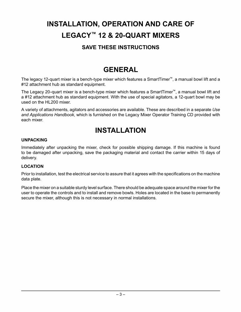
Remove and Clean Bowl Guard Wire Cage (Fig. 11)1. Rotate wire cage to your left until the three carriers align with the carrier escape slots in the
circular ridge of the planetary drip cup.2. Lift the wire cage straight up so the carriers escape from the slots on the drip cup. The bowl
guard wire cage can now be removed by pulling toward you.
3. Wash the bowl guard wire cage in a sink, rinse with clear water, and dry with a clean cloth.4. The splash guard can be wiped off and/or washed with a cloth or sponge using warm, soapy
water. Rinse with clear water and dry with a clean cloth.
Reinstall Bowl Guard Wire Cage1. Position the ring of the bowl guard wire cage so the carriers are positioned above the slots in the
planetary drip cup.2. Lower the bowl guard wire cage so the carriers pass through the slots.3. Rotate the bowl guard wire cage to your right until it contacts the stop, closed position.
Fig. 11
Escape Slots (3)

– 12 –
AGITATORS AND ATTACHMENTSAttachments for attachment hub and agitators are covered in a separate Hobart Legacy Mixer Use and Application Handbook on the Mixer Operator Information CD. Follow the instructions accordingly.
Available Agitators and Attachments
12 & 20 Qt. B Flat Beater 12 & 20 Qt. D Wire Whip
12 & 20 Qt. ED Dough Hook 12 & 20 Qt. E Dough Hook
12 & 20 Qt. SST Bowl 12 & 20 Qt. Scraper
12 & 20 Qt. Splash Cover 12 & 20 Qt. C Wing whip

– 13 –
CLEANING
Unplug machine power cord before beginning any cleaning procedure.
The mixer should be thoroughly cleaned daily. DO NOT use a hose to clean the mixer; it should be washed with a clean, damp cloth. The base allows ample room for cleaning under the mixer. The apron (Fig. 1, pg. 5) may be removed for cleaning by loosening the screws. The drip cup (Fig. 1, pg. 5) should be removed (which is secured with 3 screws) periodically and wiped clean. For cleaning the bowl guard wire cage refer to page 11.
12 & 20 Qt. P Pastry Knife 12 & 20 Qt.Ingredient Chute
12 & 20 Qt. Table

– 14 –
MAINTENANCE
Unplug machine power cord before beginning any maintenance procedure.LUBRICATION
SlidewaysThe slideways (Fig. 12) should be lubricated approximately twice a year. To reach these areas, fully lower the bowl support and remove the apron, which is secured by slotted screws. Wipe a thin coat of Lubriplate 630AA on the bowl pad area of the bowl supports and on each slideway. Install the apron.
Planetary SealOccasionally, the planetary seal (Fig. 13) may become dry and begin to squeak. To correct this, work a little lubrication (mineral oil) under the lip of the seal.
Fig. 12
Slideway
PlanetarySeal
Fig. 13
– 15 –
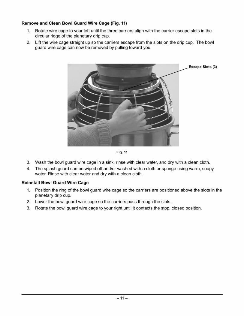
ADJUSTMENTSAgitator ClearanceThe agitator clearance should be checked periodically. The agitator must not touch the bowl, and the maximum clearance between the bottom of the bowl and the B fl at beater is 1/8" (3mm); the maximum clearance between the bottom of the bowl and the ED dough arm is 5/16” (8 mm).
Install a bowl and agitator (e.g., beater). If the bowl and beater come into contact before the bowl support reaches its stop, adjust the stop screws. Refer to Adjust the Bowl/Agitator Clearance.
Measure ClearancePour enough fl our in the bowl to cover the bottom of the bowl where the beater travels. With the bowl fully raised (beater should not touch the bottom of the bowl), briefl y run the mixer at the lowest speed.
Turn off the mixer, disconnect the electrical power supply, and measure the depth of fl our where the beater has traced a path. This measurement should be taken at several points around the bowl to assure accuracy.
Adjust the Bowl/Agitator Clearance• Remove the apron (which is secured by screws).• Adjust the clearance by moving the stop screws • (Fig. 14) counterclockwise to increase the
clearance or clockwise to decrease the clearance.• After the adjustments are made, replace the
apron and secure it with the screws.• Carefully operate the bowl lift several times to check
the adjustment.
StopScrew
Fig. 14

– 16 –
TROUBLESHOOTINGSymptoms Possible CausesMixer will not start Flashing Time Display – See Below
Branch circuit protector is in open position -check fuse or disconnect switch.Mixer is overloaded.Wire cage is not in the closed position.Bowl is not in closed (mix) position or if Bowlis not in up position.
Agitator touches bowl Bowl is not in closed (mix) position.Improper agitator clearance - see Maintenancefor adjustment procedure.Agitator is not installed properly
Planetary seal squeaks Seal requires occasional lubrication - seeMaintenance
Timer displays fl ashing alarm code(Ex. “OL1” – Motor overload)
If the error code is fl ashing – unplug machineuntil display is blank then plug back in. Ifsymptoms still exist, contact your local HobartService offi ce.
SERVICE
If service is needed on this equipment, contact your local Hobart Service offi ce at 1-888-4HOBART.
F37285 Rev. A (February 2011) PRINTED IN U.S.A.