Embed Size (px)
Citation preview
1
Interrupts & Input/Output
Chapter 12
S. Dandamudi
1998
To be used with S. Dandamudi, “Introduction to Assembly Language Programming,” Springer-Verlag, 1998.
S. Dandamudi Interrupts & I/O: Page 2
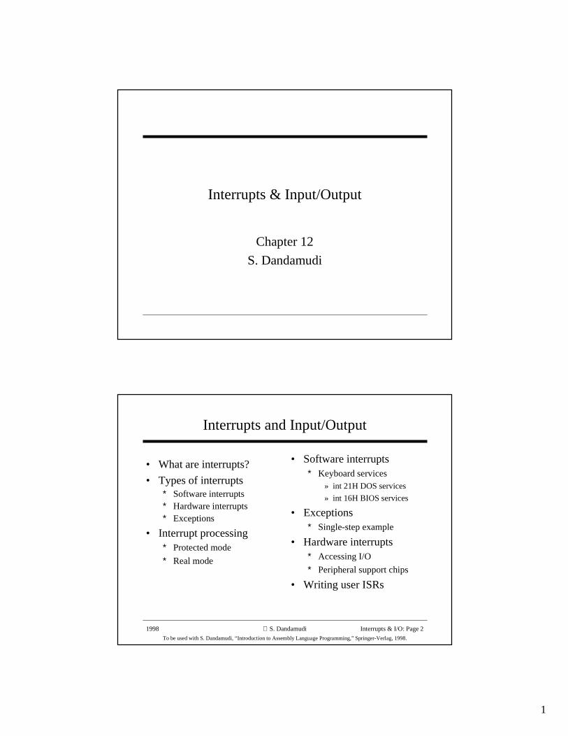
Interrupts and Input/Output
• What are interrupts?
• Types of interrupts∗ Software interrupts∗ Hardware interrupts∗ Exceptions
• Interrupt processing∗ Protected mode
∗ Real mode
• Software interrupts∗ Keyboard services
» int 21H DOS services
» int 16H BIOS services
• Exceptions∗ Single-step example
• Hardware interrupts∗ Accessing I/O
∗ Peripheral support chips
• Writing user ISRs
2
1998
To be used with S. Dandamudi, “Introduction to Assembly Language Programming,” Springer-Verlag, 1998.
S. Dandamudi Interrupts & I/O: Page 3
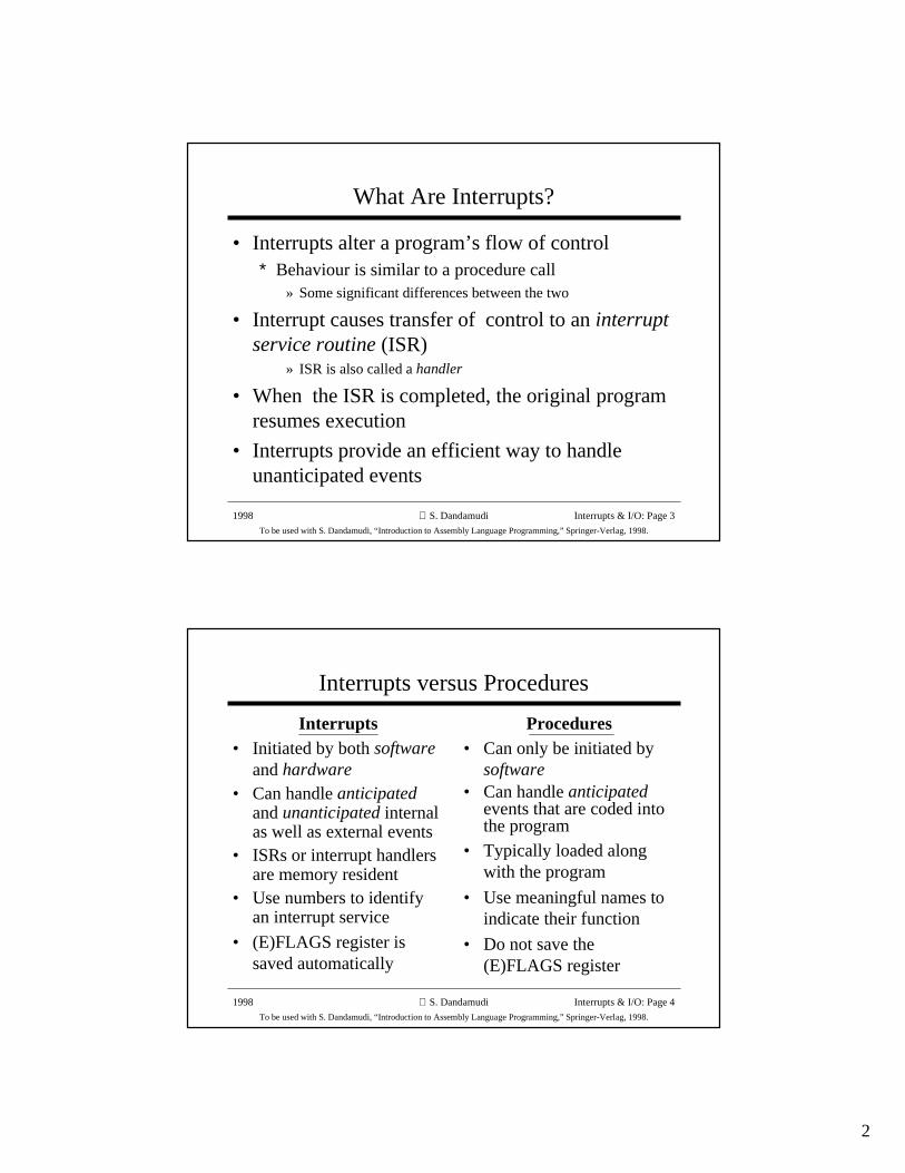
What Are Interrupts?
• Interrupts alter a program’s flow of control∗ Behaviour is similar to a procedure call
» Some significant differences between the two
• Interrupt causes transfer of control to an interruptservice routine (ISR)
» ISR is also called a handler
• When the ISR is completed, the original programresumes execution
• Interrupts provide an efficient way to handleunanticipated events
1998
To be used with S. Dandamudi, “Introduction to Assembly Language Programming,” Springer-Verlag, 1998.
S. Dandamudi Interrupts & I/O: Page 4
Interrupts versus Procedures
Interrupts• Initiated by both software
and hardware• Can handle anticipated
and unanticipated internalas well as external events
• ISRs or interrupt handlersare memory resident
• Use numbers to identifyan interrupt service
• (E)FLAGS register issaved automatically
Procedures• Can only be initiated by
software• Can handle anticipated
events that are coded intothe program
• Typically loaded alongwith the program
• Use meaningful names toindicate their function
• Do not save the(E)FLAGS register
3
1998
To be used with S. Dandamudi, “Introduction to Assembly Language Programming,” Springer-Verlag, 1998.
S. Dandamudi Interrupts & I/O: Page 5
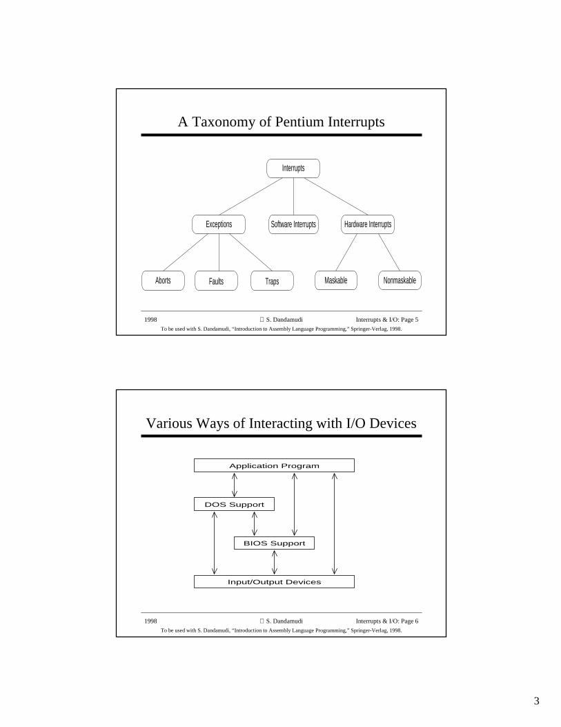
A Taxonomy of Pentium Interrupts
Maskable
Software Interrupts
TrapsAborts Faults
Interrupts
Hardware InterruptsExceptions
Nonmaskable
1998
To be used with S. Dandamudi, “Introduction to Assembly Language Programming,” Springer-Verlag, 1998.
S. Dandamudi Interrupts & I/O: Page 6
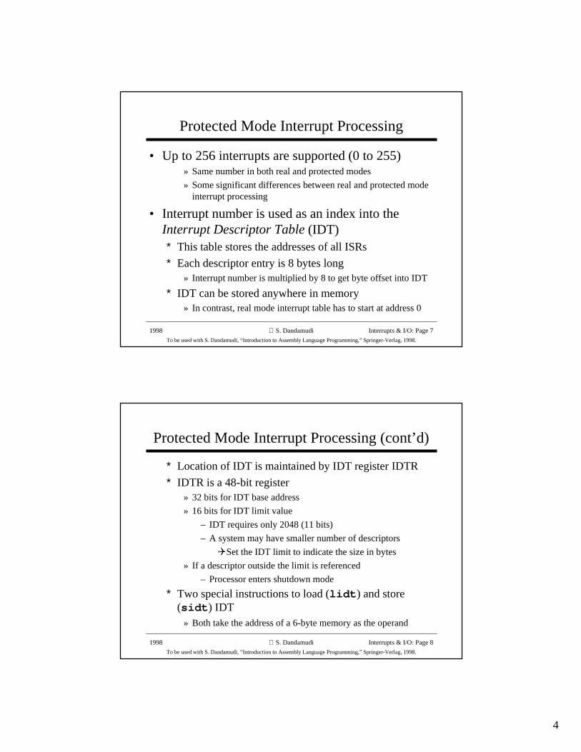
Various Ways of Interacting with I/O Devices
Application Program
Input/Output Devices
DOS Support
BIOS Support
4
1998
To be used with S. Dandamudi, “Introduction to Assembly Language Programming,” Springer-Verlag, 1998.
S. Dandamudi Interrupts & I/O: Page 7
Protected Mode Interrupt Processing
• Up to 256 interrupts are supported (0 to 255)» Same number in both real and protected modes
» Some significant differences between real and protected modeinterrupt processing
• Interrupt number is used as an index into theInterrupt Descriptor Table (IDT)∗ This table stores the addresses of all ISRs
∗ Each descriptor entry is 8 bytes long» Interrupt number is multiplied by 8 to get byte offset into IDT
∗ IDT can be stored anywhere in memory» In contrast, real mode interrupt table has to start at address 0
1998
To be used with S. Dandamudi, “Introduction to Assembly Language Programming,” Springer-Verlag, 1998.
S. Dandamudi Interrupts & I/O: Page 8
Protected Mode Interrupt Processing (cont’d)
∗ Location of IDT is maintained by IDT register IDTR
∗ IDTR is a 48-bit register» 32 bits for IDT base address
» 16 bits for IDT limit value
– IDT requires only 2048 (11 bits)
– A system may have smaller number of descriptors
�Set the IDT limit to indicate the size in bytes
» If a descriptor outside the limit is referenced
– Processor enters shutdown mode
∗ Two special instructions to load (lidt ) and store(sidt ) IDT
» Both take the address of a 6-byte memory as the operand
5
1998
To be used with S. Dandamudi, “Introduction to Assembly Language Programming,” Springer-Verlag, 1998.
S. Dandamudi Interrupts & I/O: Page 9
Interrupt Processing in Real Mode
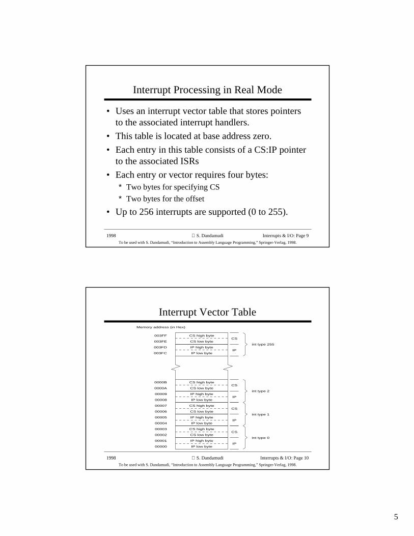
• Uses an interrupt vector table that stores pointersto the associated interrupt handlers.
• This table is located at base address zero.
• Each entry in this table consists of a CS:IP pointerto the associated ISRs
• Each entry or vector requires four bytes:∗ Two bytes for specifying CS
∗ Two bytes for the offset
• Up to 256 interrupts are supported (0 to 255).
1998
To be used with S. Dandamudi, “Introduction to Assembly Language Programming,” Springer-Verlag, 1998.
S. Dandamudi Interrupts & I/O: Page 10
Interrupt Vector Table
IP low byte
IP high byte
CS low byte
CS high byteCS
IP
int type 0
Memory address (in Hex)
IP low byte
IP high byte
CS low byte
CS high byteCS
IP
IP low byte
IP high byte
CS low byte
CS high byteCS
IP
IP low byte
IP high byte
CS low byte
CS high byteCS
IP
int type 255
int type 2
int type 1
00000
00001
00002
00003
00004
00005
00006
00007
00008
00009
0000A
0000B
003FF
003FE
003FD
003FC
6
1998
To be used with S. Dandamudi, “Introduction to Assembly Language Programming,” Springer-Verlag, 1998.
S. Dandamudi Interrupts & I/O: Page 11
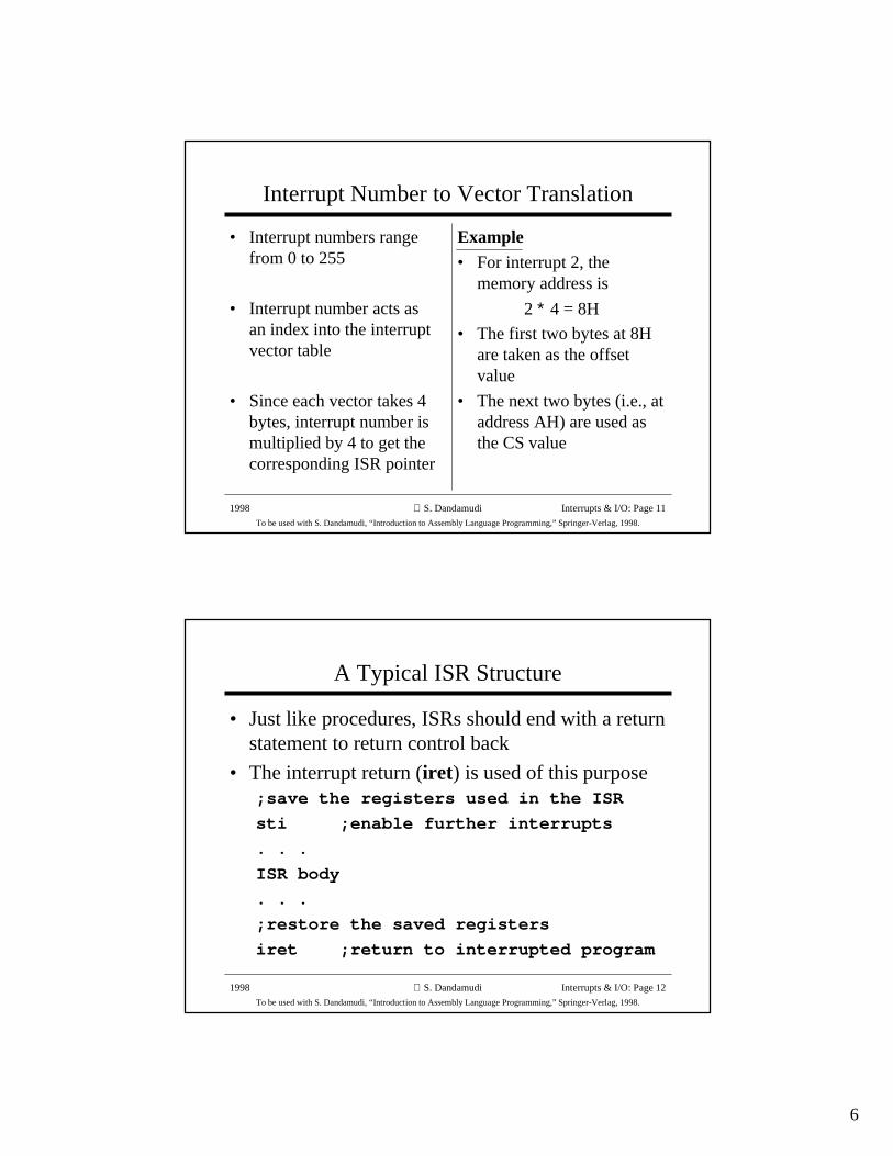
Interrupt Number to Vector Translation
• Interrupt numbers rangefrom 0 to 255
• Interrupt number acts asan index into the interruptvector table
• Since each vector takes 4bytes, interrupt number ismultiplied by 4 to get thecorresponding ISR pointer
Example• For interrupt 2, the
memory address is
2 ∗ 4 = 8H
• The first two bytes at 8Hare taken as the offsetvalue
• The next two bytes (i.e., ataddress AH) are used asthe CS value
1998
To be used with S. Dandamudi, “Introduction to Assembly Language Programming,” Springer-Verlag, 1998.
S. Dandamudi Interrupts & I/O: Page 12
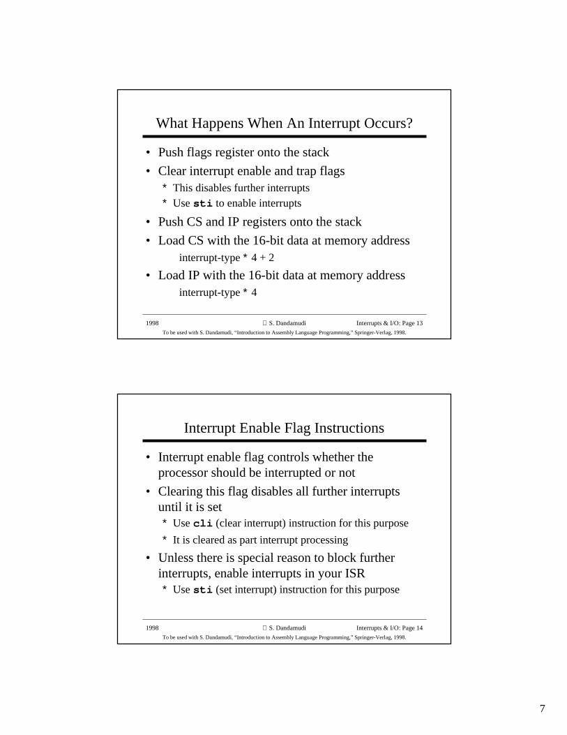
A Typical ISR Structure
• Just like procedures, ISRs should end with a returnstatement to return control back
• The interrupt return (iret ) is used of this purpose;save the registers used in the ISR
sti ;enable further interrupts
. . .
ISR body
. . .
;restore the saved registers
iret ;return to interrupted program
7
1998
To be used with S. Dandamudi, “Introduction to Assembly Language Programming,” Springer-Verlag, 1998.
S. Dandamudi Interrupts & I/O: Page 13
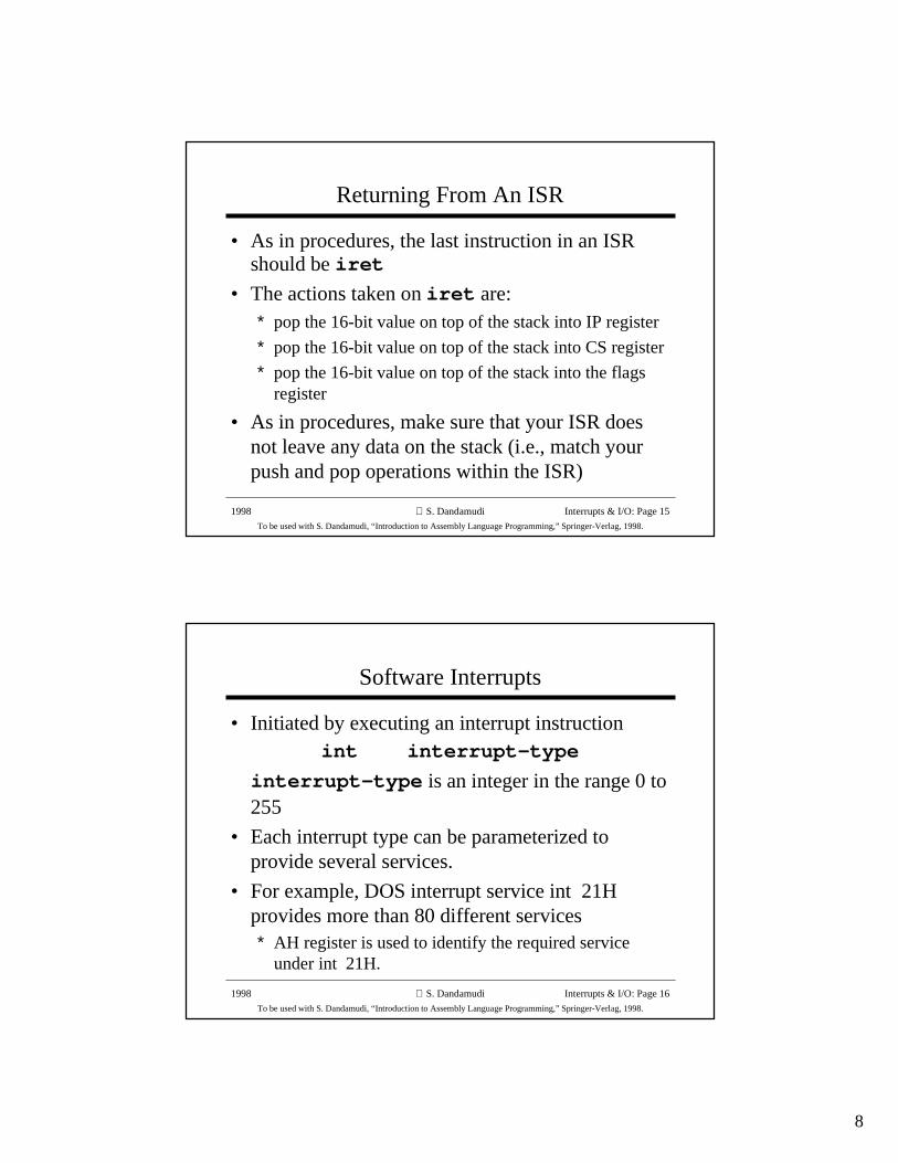
What Happens When An Interrupt Occurs?
• Push flags register onto the stack
• Clear interrupt enable and trap flags∗ This disables further interrupts∗ Use sti to enable interrupts
• Push CS and IP registers onto the stack
• Load CS with the 16-bit data at memory addressinterrupt-type ∗ 4 + 2
• Load IP with the 16-bit data at memory addressinterrupt-type ∗ 4
1998
To be used with S. Dandamudi, “Introduction to Assembly Language Programming,” Springer-Verlag, 1998.
S. Dandamudi Interrupts & I/O: Page 14
Interrupt Enable Flag Instructions
• Interrupt enable flag controls whether theprocessor should be interrupted or not
• Clearing this flag disables all further interruptsuntil it is set∗ Use cli (clear interrupt) instruction for this purpose
∗ It is cleared as part interrupt processing
• Unless there is special reason to block furtherinterrupts, enable interrupts in your ISR∗ Use sti (set interrupt) instruction for this purpose
8
1998
To be used with S. Dandamudi, “Introduction to Assembly Language Programming,” Springer-Verlag, 1998.
S. Dandamudi Interrupts & I/O: Page 15
Returning From An ISR
• As in procedures, the last instruction in an ISRshould be iret
• The actions taken on iret are:∗ pop the 16-bit value on top of the stack into IP register
∗ pop the 16-bit value on top of the stack into CS register
∗ pop the 16-bit value on top of the stack into the flagsregister
• As in procedures, make sure that your ISR doesnot leave any data on the stack (i.e., match yourpush and pop operations within the ISR)
1998
To be used with S. Dandamudi, “Introduction to Assembly Language Programming,” Springer-Verlag, 1998.
S. Dandamudi Interrupts & I/O: Page 16
Software Interrupts
• Initiated by executing an interrupt instructionint interrupt-type
interrupt-type is an integer in the range 0 to255
• Each interrupt type can be parameterized toprovide several services.
• For example, DOS interrupt service int 21Hprovides more than 80 different services∗ AH register is used to identify the required service
under int 21H.
9
1998
To be used with S. Dandamudi, “Introduction to Assembly Language Programming,” Springer-Verlag, 1998.
S. Dandamudi Interrupts & I/O: Page 17
Example DOS Service: Keyboard
• DOS provides several interrupt services to interactwith the keyboard
• AH register should be loaded with the desiredfunction under int 21H.
• Seven functions are provided by DOS to read acharacter or get the status of the keyboard
» See Section 12.5.2 for details
• We look at one function to read a string ofcharacters from the keyboard.
1998
To be used with S. Dandamudi, “Introduction to Assembly Language Programming,” Springer-Verlag, 1998.
S. Dandamudi Interrupts & I/O: Page 18
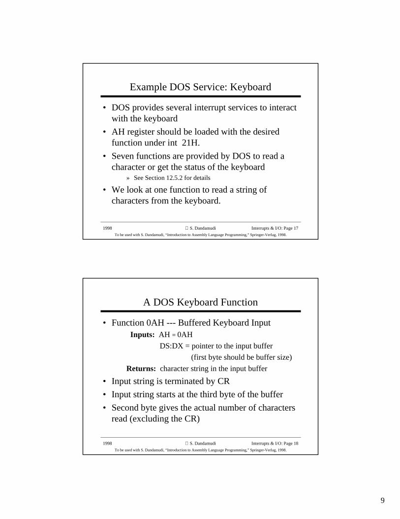
A DOS Keyboard Function
• Function 0AH --- Buffered Keyboard Input Inputs: AH = 0AH
DS:DX = pointer to the input buffer
(first byte should be buffer size)
Returns: character string in the input buffer
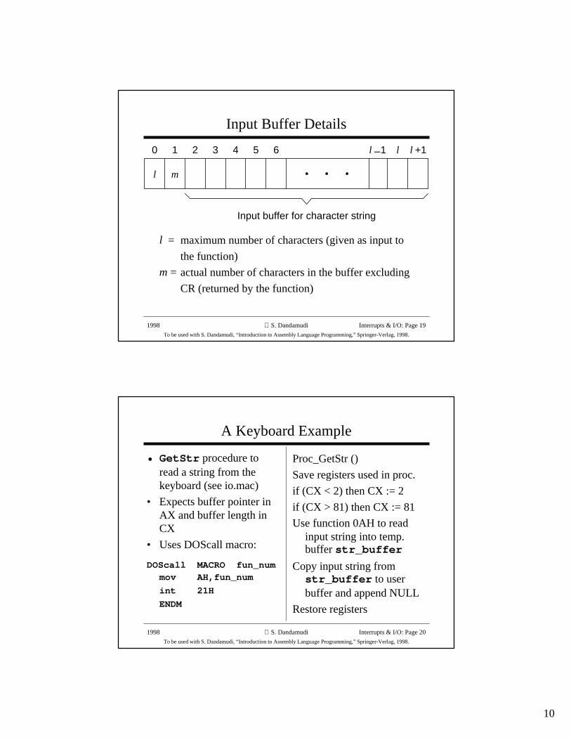
• Input string is terminated by CR
• Input string starts at the third byte of the buffer
• Second byte gives the actual number of charactersread (excluding the CR)
10
1998
To be used with S. Dandamudi, “Introduction to Assembly Language Programming,” Springer-Verlag, 1998.
S. Dandamudi Interrupts & I/O: Page 19
Input Buffer Details
l = maximum number of characters (given as input to
the function)
m = actual number of characters in the buffer excluding
CR (returned by the function)
Input buffer for character string
l m
0 1 2 3 4 5 6 l l +1_l 1
1998
To be used with S. Dandamudi, “Introduction to Assembly Language Programming,” Springer-Verlag, 1998.
S. Dandamudi Interrupts & I/O: Page 20
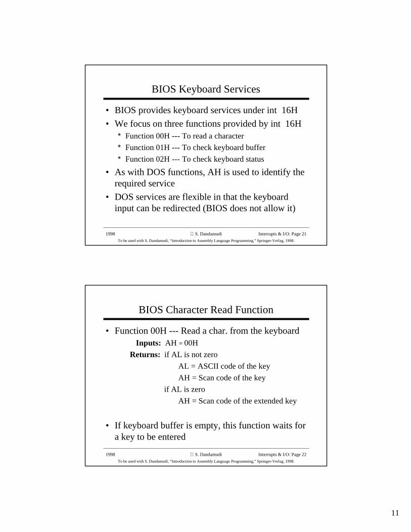
A Keyboard Example
• GetStr procedure toread a string from thekeyboard (see io.mac)
• Expects buffer pointer inAX and buffer length inCX
• Uses DOScall macro:
DOScall MACRO fun_nummov AH,fun_num
int 21H
ENDM
Proc_GetStr ()
Save registers used in proc.
if (CX < 2) then CX := 2
if (CX > 81) then CX := 81
Use function 0AH to readinput string into temp.buffer str_buffer
Copy input string fromstr_buffer to userbuffer and append NULL
Restore registers
11
1998
To be used with S. Dandamudi, “Introduction to Assembly Language Programming,” Springer-Verlag, 1998.
S. Dandamudi Interrupts & I/O: Page 21
BIOS Keyboard Services
• BIOS provides keyboard services under int 16H
• We focus on three functions provided by int 16H∗ Function 00H --- To read a character
∗ Function 01H --- To check keyboard buffer
∗ Function 02H --- To check keyboard status
• As with DOS functions, AH is used to identify therequired service
• DOS services are flexible in that the keyboardinput can be redirected (BIOS does not allow it)
1998
To be used with S. Dandamudi, “Introduction to Assembly Language Programming,” Springer-Verlag, 1998.
S. Dandamudi Interrupts & I/O: Page 22
BIOS Character Read Function
• Function 00H --- Read a char. from the keyboard Inputs: AH = 00H
Returns: if AL is not zero
AL = ASCII code of the key
AH = Scan code of the key
if AL is zero
AH = Scan code of the extended key
• If keyboard buffer is empty, this function waits fora key to be entered
12
1998
To be used with S. Dandamudi, “Introduction to Assembly Language Programming,” Springer-Verlag, 1998.
S. Dandamudi Interrupts & I/O: Page 23
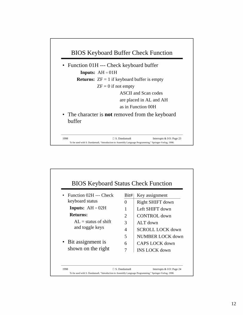
BIOS Keyboard Buffer Check Function
• Function 01H --- Check keyboard buffer Inputs: AH = 01H
Returns: ZF = 1 if keyboard buffer is empty
ZF = 0 if not empty
ASCII and Scan codes
are placed in AL and AH
as in Function 00H
• The character is not removed from the keyboardbuffer
1998
To be used with S. Dandamudi, “Introduction to Assembly Language Programming,” Springer-Verlag, 1998.
S. Dandamudi Interrupts & I/O: Page 24
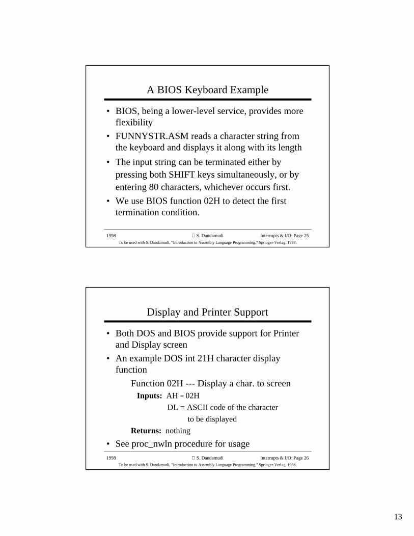
BIOS Keyboard Status Check Function
• Function 02H --- Checkkeyboard status
Inputs: AH = 02H
Returns:AL = status of shiftand toggle keys
• Bit assignment isshown on the right
Bit# Key assignment
0 Right SHIFT down
1 Left SHIFT down
2 CONTROL down
3 ALT down
4 SCROLL LOCK down
5 NUMBER LOCK down
6 CAPS LOCK down
7 INS LOCK down
13
1998
To be used with S. Dandamudi, “Introduction to Assembly Language Programming,” Springer-Verlag, 1998.
S. Dandamudi Interrupts & I/O: Page 25
A BIOS Keyboard Example
• BIOS, being a lower-level service, provides moreflexibility
• FUNNYSTR.ASM reads a character string fromthe keyboard and displays it along with its length
• The input string can be terminated either bypressing both SHIFT keys simultaneously, or byentering 80 characters, whichever occurs first.
• We use BIOS function 02H to detect the firsttermination condition.
1998
To be used with S. Dandamudi, “Introduction to Assembly Language Programming,” Springer-Verlag, 1998.
S. Dandamudi Interrupts & I/O: Page 26
Display and Printer Support
• Both DOS and BIOS provide support for Printerand Display screen
• An example DOS int 21H character displayfunction
Function 02H --- Display a char. to screen Inputs: AH = 02H
DL = ASCII code of the character
to be displayed
Returns: nothing
• See proc_nwln procedure for usage
14
1998
To be used with S. Dandamudi, “Introduction to Assembly Language Programming,” Springer-Verlag, 1998.
S. Dandamudi Interrupts & I/O: Page 27
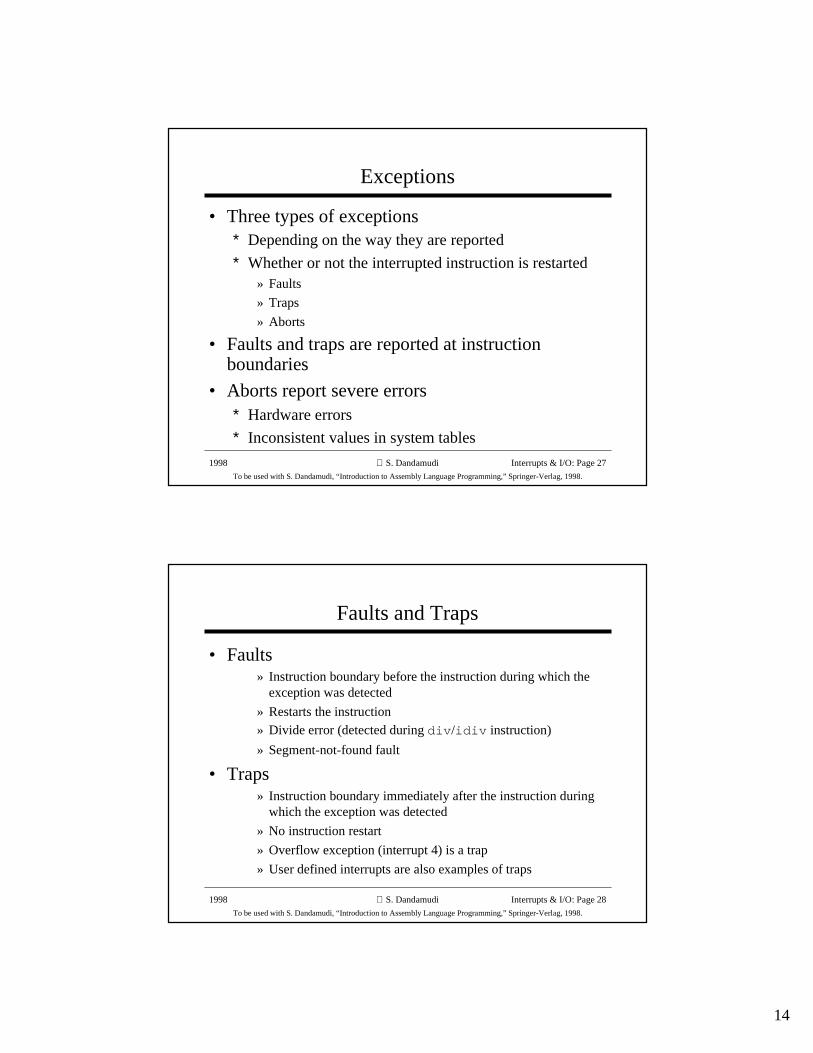
Exceptions
• Three types of exceptions∗ Depending on the way they are reported
∗ Whether or not the interrupted instruction is restarted» Faults
» Traps
» Aborts
• Faults and traps are reported at instructionboundaries
• Aborts report severe errors∗ Hardware errors
∗ Inconsistent values in system tables
1998
To be used with S. Dandamudi, “Introduction to Assembly Language Programming,” Springer-Verlag, 1998.
S. Dandamudi Interrupts & I/O: Page 28
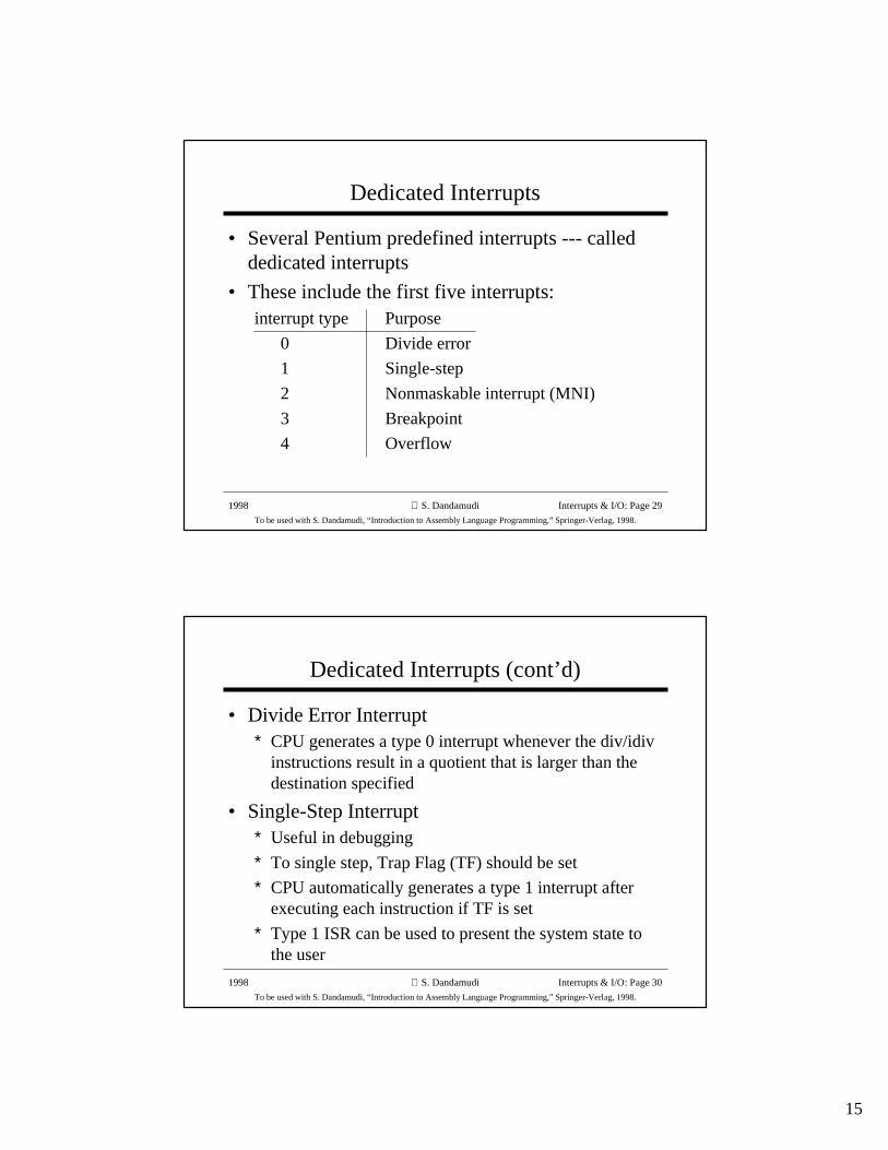
Faults and Traps
• Faults» Instruction boundary before the instruction during which the
exception was detected
» Restarts the instruction» Divide error (detected during div /idiv instruction)
» Segment-not-found fault
• Traps» Instruction boundary immediately after the instruction during
which the exception was detected
» No instruction restart
» Overflow exception (interrupt 4) is a trap
» User defined interrupts are also examples of traps
15
1998
To be used with S. Dandamudi, “Introduction to Assembly Language Programming,” Springer-Verlag, 1998.
S. Dandamudi Interrupts & I/O: Page 29
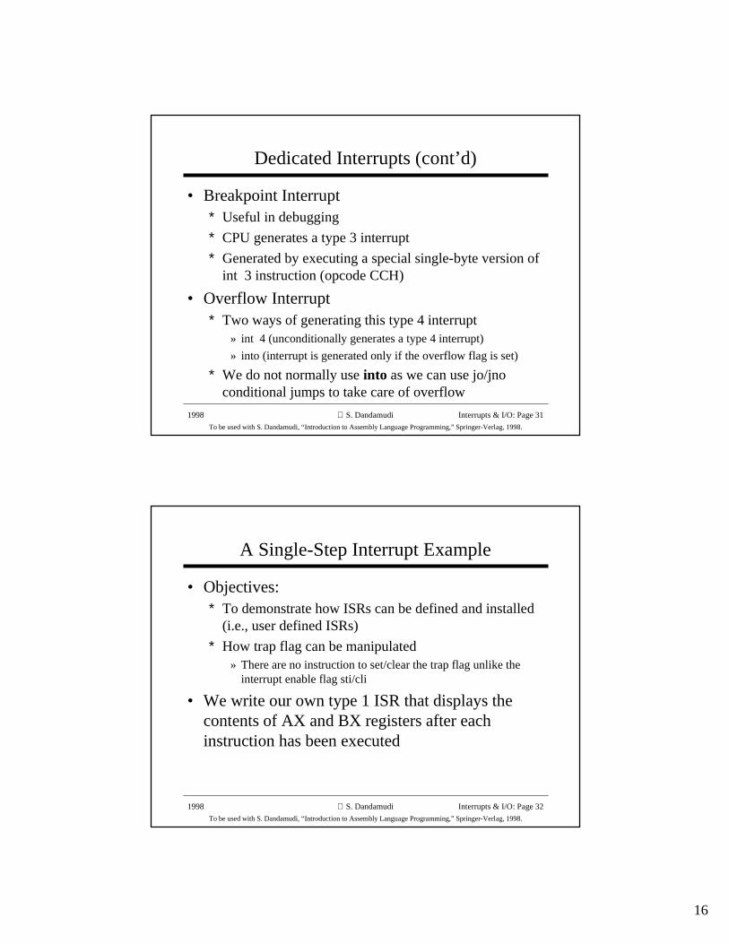
Dedicated Interrupts
• Several Pentium predefined interrupts --- calleddedicated interrupts
• These include the first five interrupts:interrupt type Purpose
0 Divide error
1 Single-step
2 Nonmaskable interrupt (MNI)
3 Breakpoint
4 Overflow
1998
To be used with S. Dandamudi, “Introduction to Assembly Language Programming,” Springer-Verlag, 1998.
S. Dandamudi Interrupts & I/O: Page 30
Dedicated Interrupts (cont’d)
• Divide Error Interrupt∗ CPU generates a type 0 interrupt whenever the div/idiv
instructions result in a quotient that is larger than thedestination specified
• Single-Step Interrupt∗ Useful in debugging
∗ To single step, Trap Flag (TF) should be set
∗ CPU automatically generates a type 1 interrupt afterexecuting each instruction if TF is set
∗ Type 1 ISR can be used to present the system state tothe user
16
1998
To be used with S. Dandamudi, “Introduction to Assembly Language Programming,” Springer-Verlag, 1998.
S. Dandamudi Interrupts & I/O: Page 31
Dedicated Interrupts (cont’d)
• Breakpoint Interrupt∗ Useful in debugging
∗ CPU generates a type 3 interrupt
∗ Generated by executing a special single-byte version ofint 3 instruction (opcode CCH)
• Overflow Interrupt∗ Two ways of generating this type 4 interrupt
» int 4 (unconditionally generates a type 4 interrupt)
» into (interrupt is generated only if the overflow flag is set)
∗ We do not normally use into as we can use jo/jnoconditional jumps to take care of overflow
1998
To be used with S. Dandamudi, “Introduction to Assembly Language Programming,” Springer-Verlag, 1998.
S. Dandamudi Interrupts & I/O: Page 32
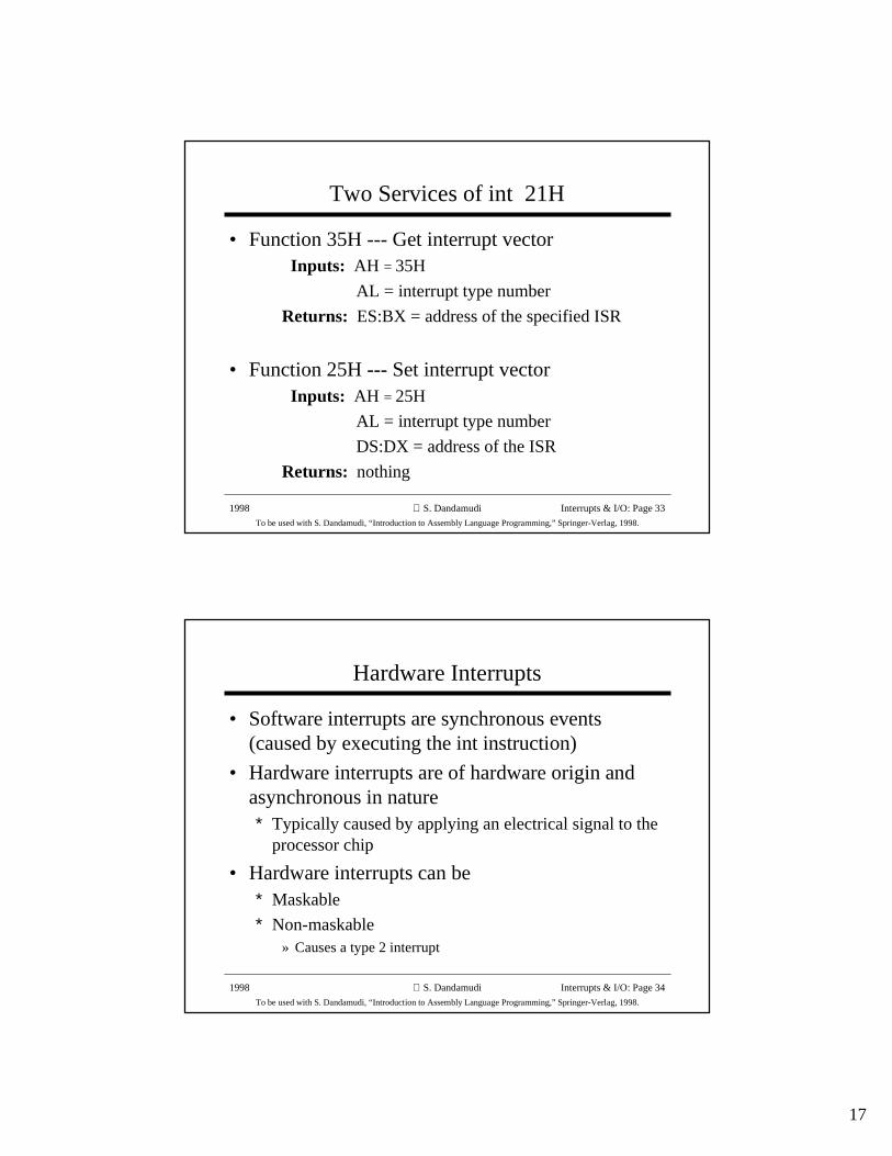
A Single-Step Interrupt Example
• Objectives:∗ To demonstrate how ISRs can be defined and installed
(i.e., user defined ISRs)
∗ How trap flag can be manipulated» There are no instruction to set/clear the trap flag unlike the
interrupt enable flag sti/cli
• We write our own type 1 ISR that displays thecontents of AX and BX registers after eachinstruction has been executed
17
1998
To be used with S. Dandamudi, “Introduction to Assembly Language Programming,” Springer-Verlag, 1998.
S. Dandamudi Interrupts & I/O: Page 33
Two Services of int 21H
• Function 35H --- Get interrupt vector Inputs: AH = 35H
AL = interrupt type number
Returns: ES:BX = address of the specified ISR
• Function 25H --- Set interrupt vector Inputs: AH = 25H
AL = interrupt type number
DS:DX = address of the ISR
Returns: nothing
1998
To be used with S. Dandamudi, “Introduction to Assembly Language Programming,” Springer-Verlag, 1998.
S. Dandamudi Interrupts & I/O: Page 34
Hardware Interrupts
• Software interrupts are synchronous events(caused by executing the int instruction)
• Hardware interrupts are of hardware origin andasynchronous in nature∗ Typically caused by applying an electrical signal to the
processor chip
• Hardware interrupts can be∗ Maskable
∗ Non-maskable» Causes a type 2 interrupt
18
1998
To be used with S. Dandamudi, “Introduction to Assembly Language Programming,” Springer-Verlag, 1998.
S. Dandamudi Interrupts & I/O: Page 35
How Are Hardware Interrupts Triggered?
• Non-maskable interrupt is triggered by applyingan electrical signal to the MNI pin of Pentium∗ Processor always responds to this signal
∗ Cannot be disabled under program control
• Maskable interrupt is triggered by applying anelectrical signal to the INTR (INTerrupt Request)pin of Pentium∗ Pentium recognizes this interrupt only if IF (interrupt
enable flag) is set
∗ Interrupts can be masked or disabled by clearing IF
1998
To be used with S. Dandamudi, “Introduction to Assembly Language Programming,” Springer-Verlag, 1998.
S. Dandamudi Interrupts & I/O: Page 36
How Does the CPU Know the Interrupt Type?
• Interrupt invocation process is common to allinterrupts -- whether originated in software orhardware
• For hardware interrupts, CPU initiates an interruptacknowledge sequence∗ CPU sends out interrupt acknowledge (INTA) signal
∗ In response, interrupting device places interrupt typenumber on the data bus
∗ CPU uses this number to invoke the ISR that shouldservice the device (as in software interrupts)
19
1998
To be used with S. Dandamudi, “Introduction to Assembly Language Programming,” Springer-Verlag, 1998.
S. Dandamudi Interrupts & I/O: Page 37
How can More Than One Device Interrupt?
• Processor has only one INTR pin to receiveinterrupt signal
• Typical system has more than one device that caninterrupt --- keyboard, hard disk, floppy, etc.
• Use a special chip to prioritize the interrupts andforward only one interrupt to the CPU
• 8259 Programmable Interrupt Controller chipperforms this function (more details later)
1998
To be used with S. Dandamudi, “Introduction to Assembly Language Programming,” Springer-Verlag, 1998.
S. Dandamudi Interrupts & I/O: Page 38
Direct Control of I/O Devices
• Two ways of mapping I/O ports:∗ Memory-mapped I/O (e.g., Motorola 68000)
» I/O port is treated as a memory address (I/O port is mapped toa location in memory address space (MAS))
» Accessing an I/O port (read/write) is similar to accessing amemory location (all memory access instructions can be used)
∗ Isolated I/O (e.g., Pentium)» I/O address space is separate from the memory address space
– leaves the complete MAS for memory
» Separate I/O instructions and I/O signals are needed
» Can’t use memory access instructions» Can also use memory-mapped I/O and use all memory access
instructions
20
1998
To be used with S. Dandamudi, “Introduction to Assembly Language Programming,” Springer-Verlag, 1998.
S. Dandamudi Interrupts & I/O: Page 39
Pentium I/O Address Space
• Pentium provides 64 KB of I/O address space∗ Can be used for 8-, 16-, and 32-bit I/O ports
• Combination cannot exceed the total I/O space∗ 64K 8-bit I/O ports
» Used for 8-bit devices, which transfer 8-bit data
» Can be located anywhere in the I/O space
∗ 32K 16-bit I/O ports (used for 16-bit devices)» 16-bit ports should be aligned to an even address
∗ 16K 32-bit I/O ports (used for 32-bit devices)» Should be aligned to addresses that are multiples of four
» Pentium supports unaligned ports, but with performance penalty
∗ A combination of these for a total of 64 KB
1998
To be used with S. Dandamudi, “Introduction to Assembly Language Programming,” Springer-Verlag, 1998.
S. Dandamudi Interrupts & I/O: Page 40
Pentium I/O Instructions
• Pentium provides two types of I/O instructions:∗ Register I/O instructions
» used to transfer data between a register (accumulator) and anI/O port
» in - to read from an I/O port
» out - to write to an I/O port
∗ Block I/O instructions» used to transfer a block of data between memory and an I/O
port» ins - to read from an I/O port
» outs - to write to an I/O port
21
1998
To be used with S. Dandamudi, “Introduction to Assembly Language Programming,” Springer-Verlag, 1998.
S. Dandamudi Interrupts & I/O: Page 41
Register I/O Instructions
• Can take one of two forms depending on whethera port is directly addressable or not
– A port is said to be directly addressable if it is within thefirst 256 ports (so that one byte can be used specify it)
• To read from an I/O portin accumulator,port8 -- direct addressing format
port8 is 8-bit port number
in accumulator,DX -- indirect addressing format port number should be loaded into DX
accumulator can be AL, AX, or EAX (depending on I/O port)
• To write to an I/O portout port8,accumulator -- direct addressing formatout DX,accumulator -- indirect addressing format
1998
To be used with S. Dandamudi, “Introduction to Assembly Language Programming,” Springer-Verlag, 1998.
S. Dandamudi Interrupts & I/O: Page 42
Block I/O Instructions
• Similar to string instructions• ins and outs do not take any operands
• I/O port address should be in DX∗ No direct addressing format is allowed
• ins instruction to read from an I/O port» ES:(E)DI should point to memory buffer
• outs instruction to write to an I/O port» DS:(E)SI should point to memory buffer
• rep prefix can be used for block transfer of dataas in the string instructions
22
1998
To be used with S. Dandamudi, “Introduction to Assembly Language Programming,” Springer-Verlag, 1998.
S. Dandamudi Interrupts & I/O: Page 43
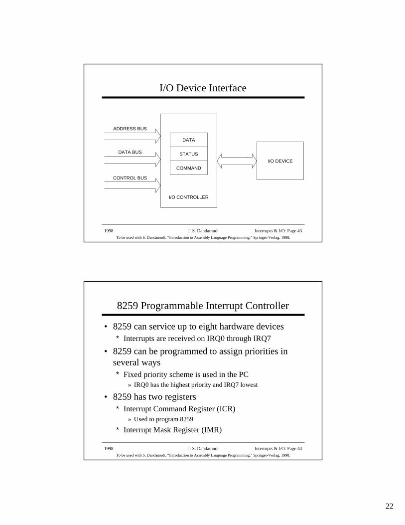
I/O Device Interface
CONTROL BUS
DATA BUS
ADDRESS BUS
STATUS
COMMAND
DATA
I/O CONTROLLER
I/O DEVICE
1998
To be used with S. Dandamudi, “Introduction to Assembly Language Programming,” Springer-Verlag, 1998.
S. Dandamudi Interrupts & I/O: Page 44
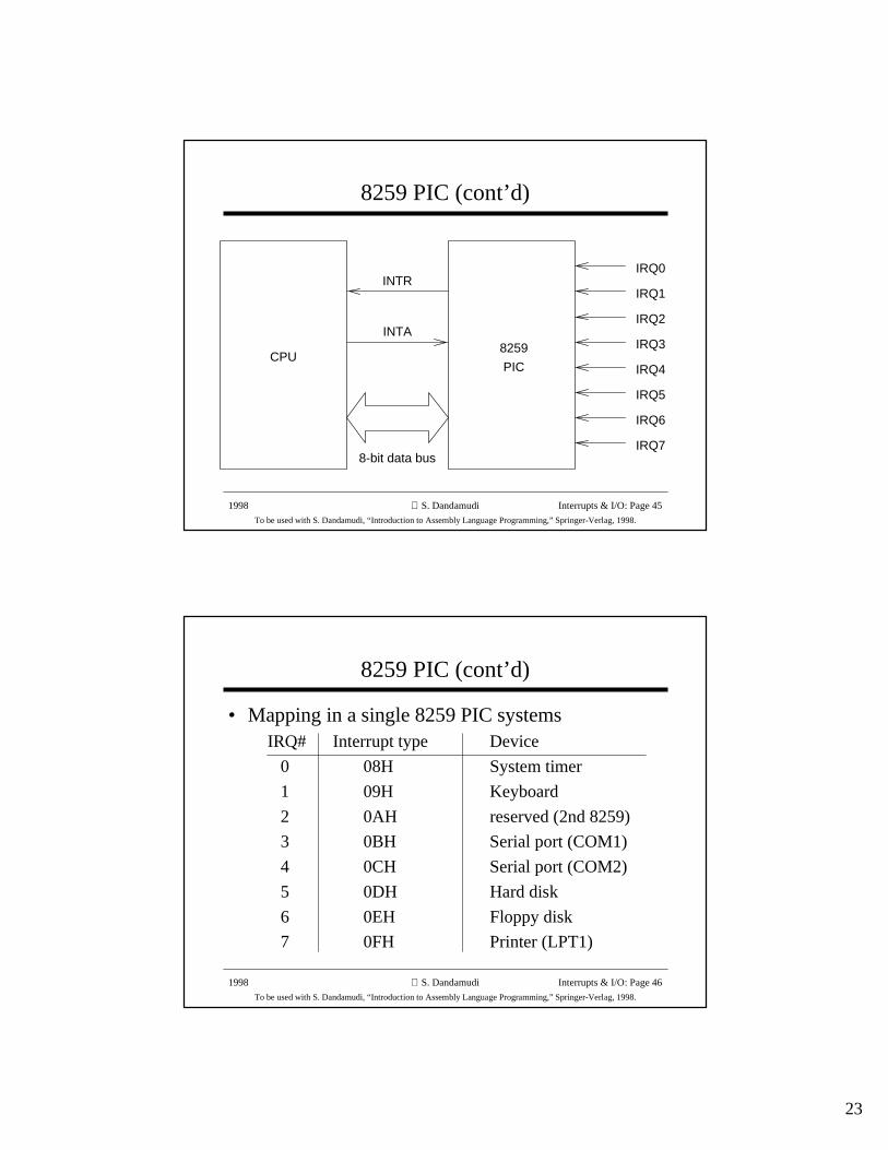
8259 Programmable Interrupt Controller
• 8259 can service up to eight hardware devices∗ Interrupts are received on IRQ0 through IRQ7
• 8259 can be programmed to assign priorities inseveral ways∗ Fixed priority scheme is used in the PC
» IRQ0 has the highest priority and IRQ7 lowest
• 8259 has two registers∗ Interrupt Command Register (ICR)
» Used to program 8259
∗ Interrupt Mask Register (IMR)
23
1998
To be used with S. Dandamudi, “Introduction to Assembly Language Programming,” Springer-Verlag, 1998.
S. Dandamudi Interrupts & I/O: Page 45
8259 PIC (cont’d)
8259
PIC
IRQ0
IRQ1
IRQ2
IRQ3
IRQ4
IRQ5
IRQ6
IRQ7
INTR
INTA
8-bit data bus
CPU
1998
To be used with S. Dandamudi, “Introduction to Assembly Language Programming,” Springer-Verlag, 1998.
S. Dandamudi Interrupts & I/O: Page 46
8259 PIC (cont’d)
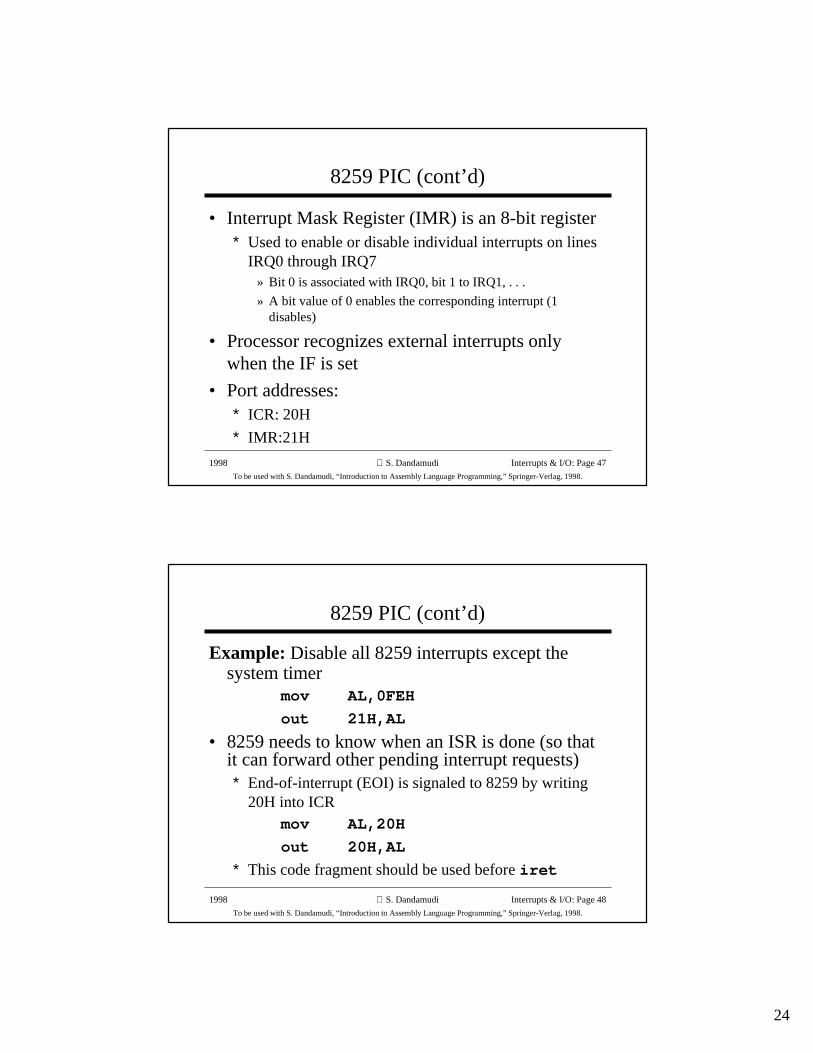
• Mapping in a single 8259 PIC systems IRQ# Interrupt type Device
0 08H System timer
1 09H Keyboard
2 0AH reserved (2nd 8259)
3 0BH Serial port (COM1)
4 0CH Serial port (COM2)
5 0DH Hard disk
6 0EH Floppy disk
7 0FH Printer (LPT1)
24
1998
To be used with S. Dandamudi, “Introduction to Assembly Language Programming,” Springer-Verlag, 1998.
S. Dandamudi Interrupts & I/O: Page 47
8259 PIC (cont’d)
• Interrupt Mask Register (IMR) is an 8-bit register∗ Used to enable or disable individual interrupts on lines
IRQ0 through IRQ7» Bit 0 is associated with IRQ0, bit 1 to IRQ1, . . .
» A bit value of 0 enables the corresponding interrupt (1disables)
• Processor recognizes external interrupts onlywhen the IF is set
• Port addresses:∗ ICR: 20H
∗ IMR:21H
1998
To be used with S. Dandamudi, “Introduction to Assembly Language Programming,” Springer-Verlag, 1998.
S. Dandamudi Interrupts & I/O: Page 48
8259 PIC (cont’d)
Example: Disable all 8259 interrupts except thesystem timer
mov AL,0FEH
out 21H,AL
• 8259 needs to know when an ISR is done (so thatit can forward other pending interrupt requests)∗ End-of-interrupt (EOI) is signaled to 8259 by writing
20H into ICRmov AL,20H
out 20H,AL
∗ This code fragment should be used before iret
25
1998
To be used with S. Dandamudi, “Introduction to Assembly Language Programming,” Springer-Verlag, 1998.
S. Dandamudi Interrupts & I/O: Page 49
8255 Programmable Peripheral Interface Chip
• Provides three 8-bit registers (PA, PB, PC) thatcan be used to interface with I/O devices
• These three ports are configures as follows:PA -- Input port
PB -- Output port
PC -- Input port
• 8255 also has a command register• 8255 port address mapping
PA --- 60H
PB --- 61H
PC --- 62H
Command register --- 63H
1998
To be used with S. Dandamudi, “Introduction to Assembly Language Programming,” Springer-Verlag, 1998.
S. Dandamudi Interrupts & I/O: Page 50
Keyboard Interface
• PA and PB7 are used for keyboard interface∗ PA0 -- PA6 = key scan code
∗ PA7 = 0 if a key is depressed
∗ PA7 = 1 if a key is released
• Keyboard provides the scan code on PA and waitsfor an acknowledgement∗ Scan code read acknowledge signal is provided by
momentarily setting and clearing PB7» Normal state of PB7 is 0
• Keyboard generates IRQ1» IRQ1 generates a type 9 interrupt
26
1998
To be used with S. Dandamudi, “Introduction to Assembly Language Programming,” Springer-Verlag, 1998.
S. Dandamudi Interrupts & I/O: Page 51
Polling Versus Interrupts
• Using interrupts to service I/O requests is calledinterrupt-driven I/O
• An alternative is programmed I/O∗ Repeatedly checks the status of an I/O device (through
a status register of the associated I/O controller) untilthe desired condition is indicated
∗ This process is called polling
• Interrupt-driven I/O is efficient» Can be used to handle unanticipated events
• Polling involves overhead» Can be used to handle only anticipated event
1998
To be used with S. Dandamudi, “Introduction to Assembly Language Programming,” Springer-Verlag, 1998.
S. Dandamudi Interrupts & I/O: Page 52
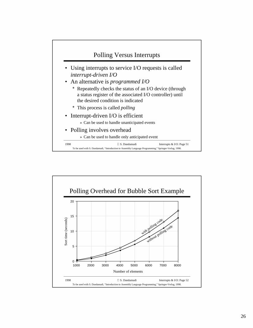
Polling Overhead for Bubble Sort Example
Sort
tim
e (s
econ
ds)
Number of elements
0
5
10
15
20
1000 2000 3000 4000 5000 6000 7000 8000
with pollin
g code
without polling code