Embed Size (px)
Citation preview
Fabiola Buitrago G. Ph.D.
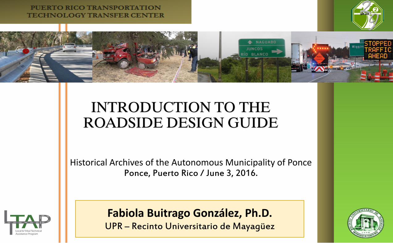
INTRODUCTION TO THE
ROADSIDE DESIGN GUIDE
Historical Archives of the Autonomous Municipality of Ponce Ponce, Puerto Rico / June 3, 2016.
Fabiola Buitrago González, Ph.D. UPR – Recinto Universitario de Mayagüez
Fabiola Buitrago G. Ph.D.
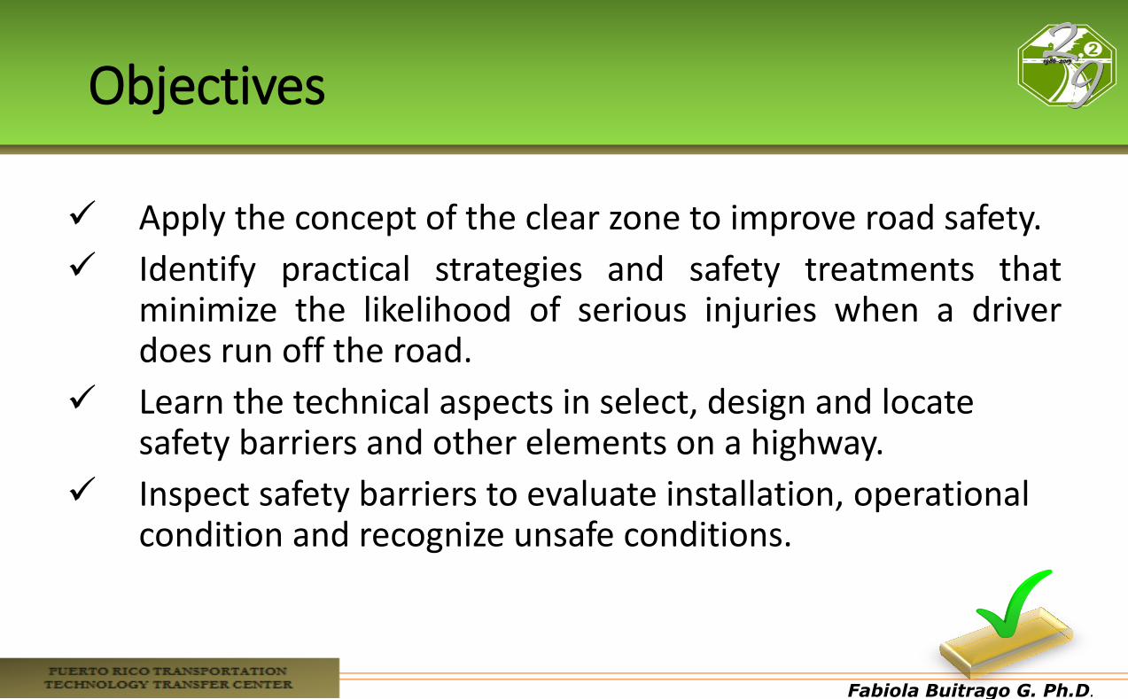
Objectives
Apply the concept of the clear zone to improve road safety.
Identify practical strategies and safety treatments that minimize the likelihood of serious injuries when a driver does run off the road.
Learn the technical aspects in select, design and locate safety barriers and other elements on a highway.
Inspect safety barriers to evaluate installation, operational condition and recognize unsafe conditions.

Fabiola Buitrago G. Ph.D.
Fabiola Buitrago G. Ph.D.
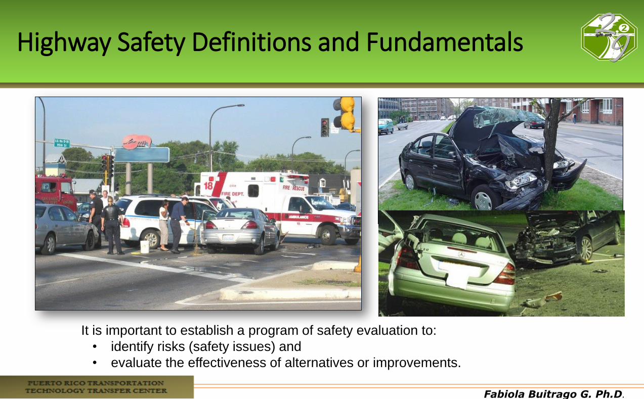
Highway Safety Definitions and Fundamentals
It is important to establish a program of safety evaluation to:
• identify risks (safety issues) and
• evaluate the effectiveness of alternatives or improvements.
Fabiola Buitrago G. Ph.D.
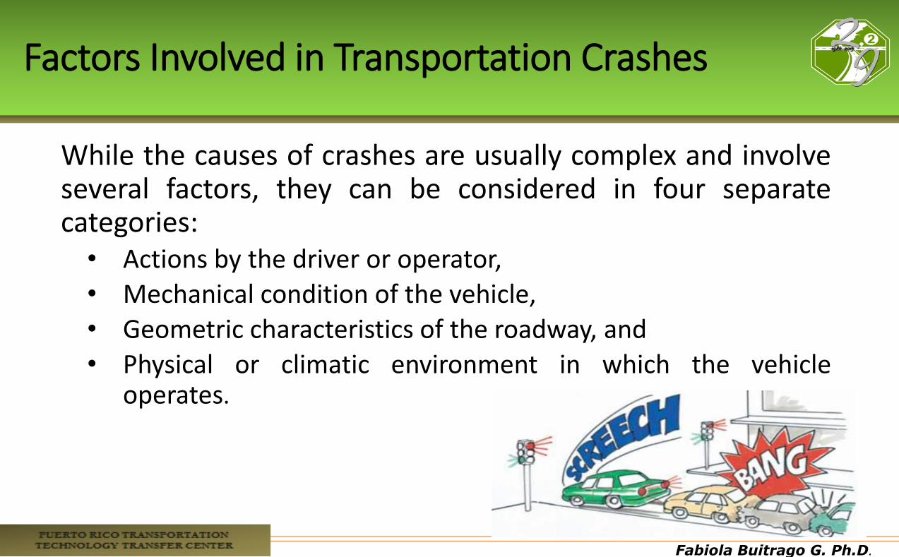
Factors Involved in Transportation Crashes
While the causes of crashes are usually complex and involve several factors, they can be considered in four separate categories: • Actions by the driver or operator, • Mechanical condition of the vehicle, • Geometric characteristics of the roadway, and • Physical or climatic environment in which the vehicle
operates.

Fabiola Buitrago G. Ph.D.
Crash Cause by Factor
Fabiola Buitrago G. Ph.D.
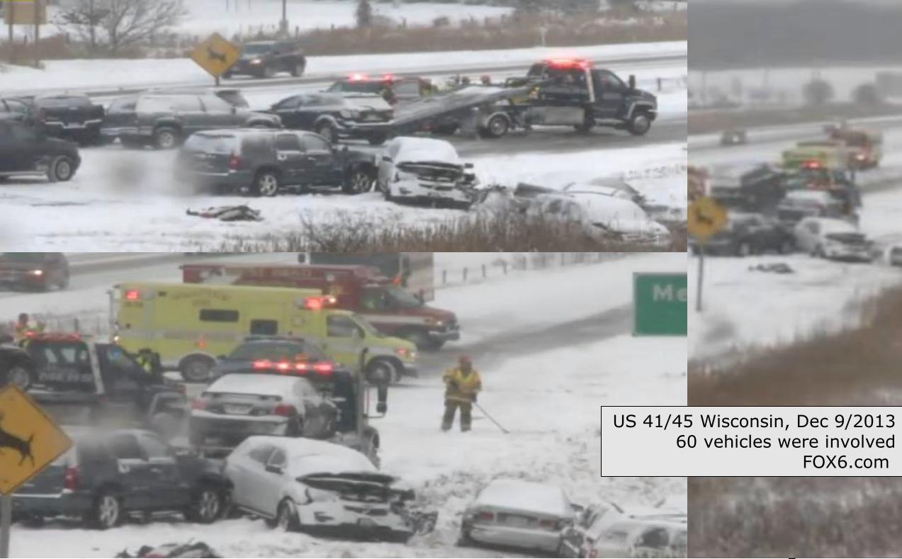
US 41/45 Wisconsin, Dec 9/2013 60 vehicles were involved
FOX6.com
Fabiola Buitrago G. Ph.D.
Strategic Highway Safety Plans
• SAFETEA-LU: The Safe Accountable, Flexible, Efficient Transportation Equity Act: A Legacy for Users legislation of 2005 • New “Core” Highway Safety Improvement Program
SAFETEA-LU Doubles TEA-21 Safety Apportionment • Requires that each state develop a Strategic Highway
Safety Plan (SHSP). • Purpose: to achieve a significant reduction in traffic
fatalities and serious injuries on public roads
Fabiola Buitrago G. Ph.D.
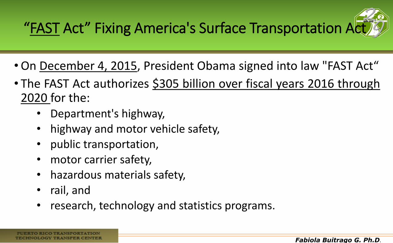
“FAST Act” Fixing America's Surface Transportation Act
•On December 4, 2015, President Obama signed into law "FAST Act“
• The FAST Act authorizes $305 billion over fiscal years 2016 through 2020 for the:
• Department's highway, • highway and motor vehicle safety, • public transportation, • motor carrier safety, • hazardous materials safety, • rail, and • research, technology and statistics programs.
Fabiola Buitrago G. Ph.D.
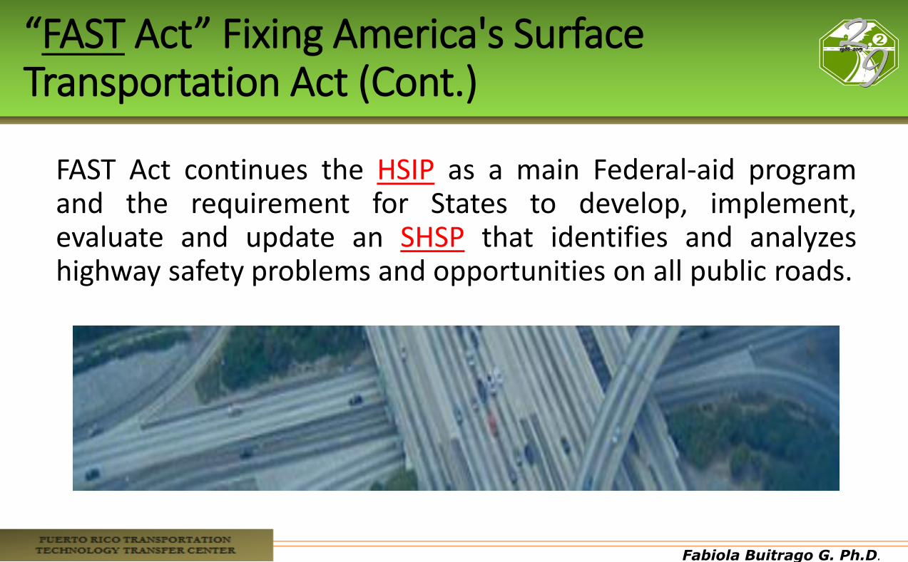
“FAST Act” Fixing America's Surface Transportation Act (Cont.)
FAST Act continues the HSIP as a main Federal-aid program and the requirement for States to develop, implement, evaluate and update an SHSP that identifies and analyzes highway safety problems and opportunities on all public roads.
Fabiola Buitrago G. Ph.D.
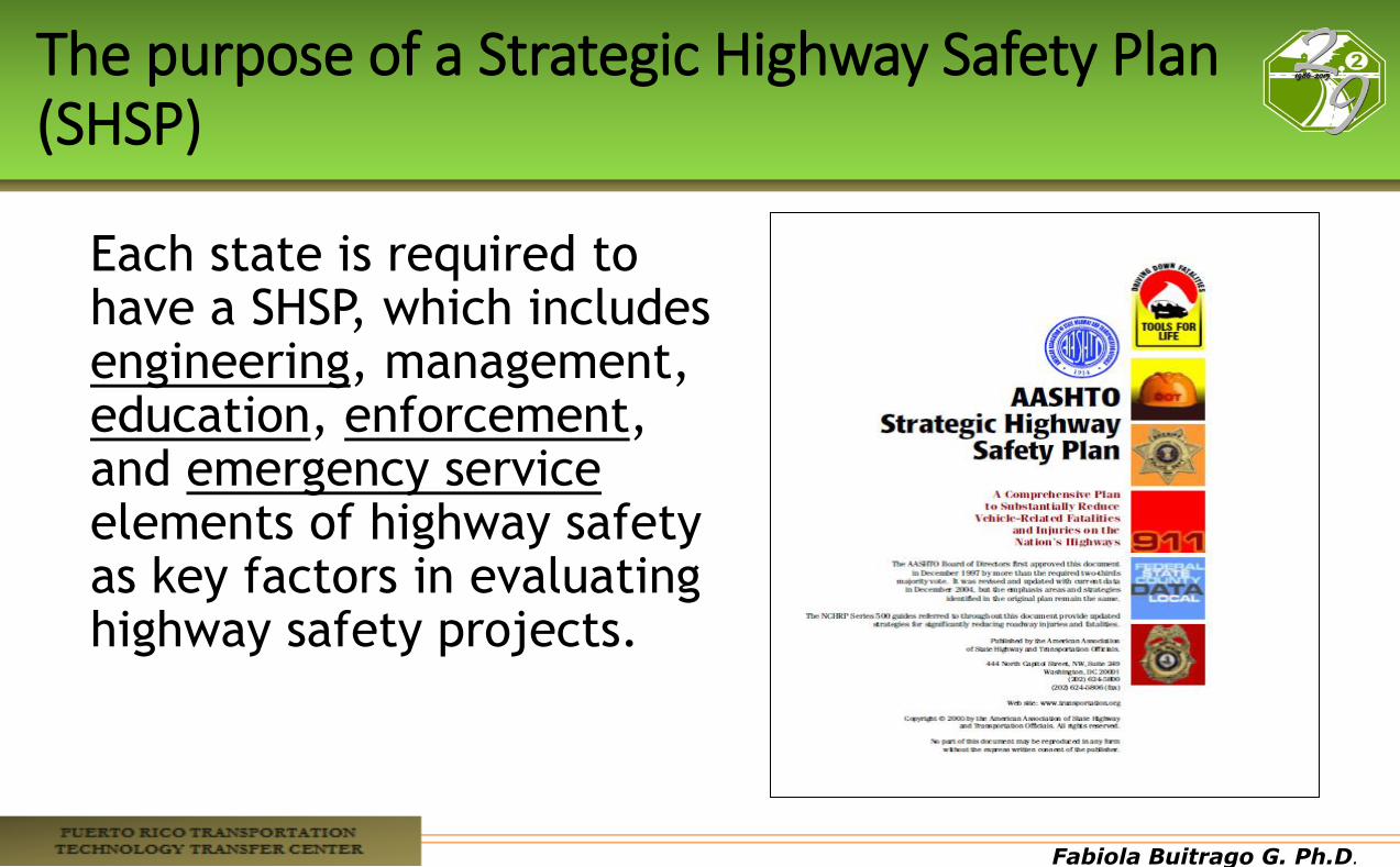
The purpose of a Strategic Highway Safety Plan (SHSP)
Each state is required to have a SHSP, which includes engineering, management, education, enforcement, and emergency service elements of highway safety as key factors in evaluating highway safety projects.
Fabiola Buitrago G. Ph.D.
Fabiola Buitrago G. Ph.D.
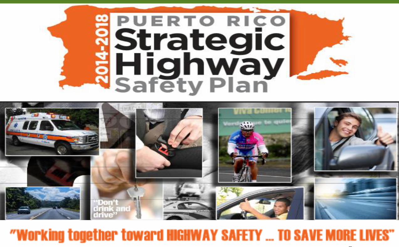
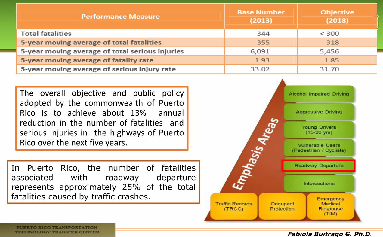
The overall objective and public policy adopted by the commonwealth of Puerto Rico is to achieve about 13% annual reduction in the number of fatalities and serious injuries in the highways of Puerto Rico over the next five years.
In Puerto Rico, the number of fatalities associated with roadway departure represents approximately 25% of the total fatalities caused by traffic crashes.
Fabiola Buitrago G. Ph.D.
Fabiola Buitrago G. Ph.D.
Fabiola Buitrago G. Ph.D.
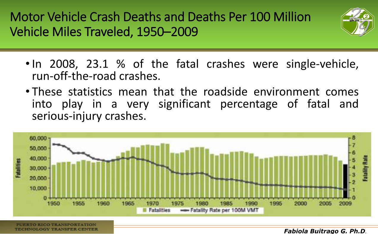
Motor Vehicle Crash Deaths and Deaths Per 100 Million Vehicle Miles Traveled, 1950–2009
• In 2008, 23.1 % of the fatal crashes were single-vehicle, run-off-the-road crashes.
• These statistics mean that the roadside environment comes into play in a very significant percentage of fatal and serious-injury crashes.
Fabiola Buitrago G. Ph.D.
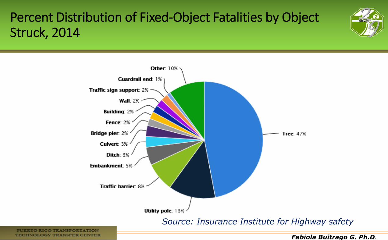
Percent Distribution of Fixed-Object Fatalities by Object Struck, 2014
Source: Insurance Institute for Highway safety
Fabiola Buitrago G. Ph.D.
Why Would a Vehicle Leave the Highway?
• Driver fatigue • Driver distractions or inattention • Excessive speed • Driving under the influence of drugs or alcohol • Crash avoidance • Adverse roadway conditions, such as ice, snow, or
rain • Vehicle failure • Poor visibility
Fabiola Buitrago G. Ph.D.
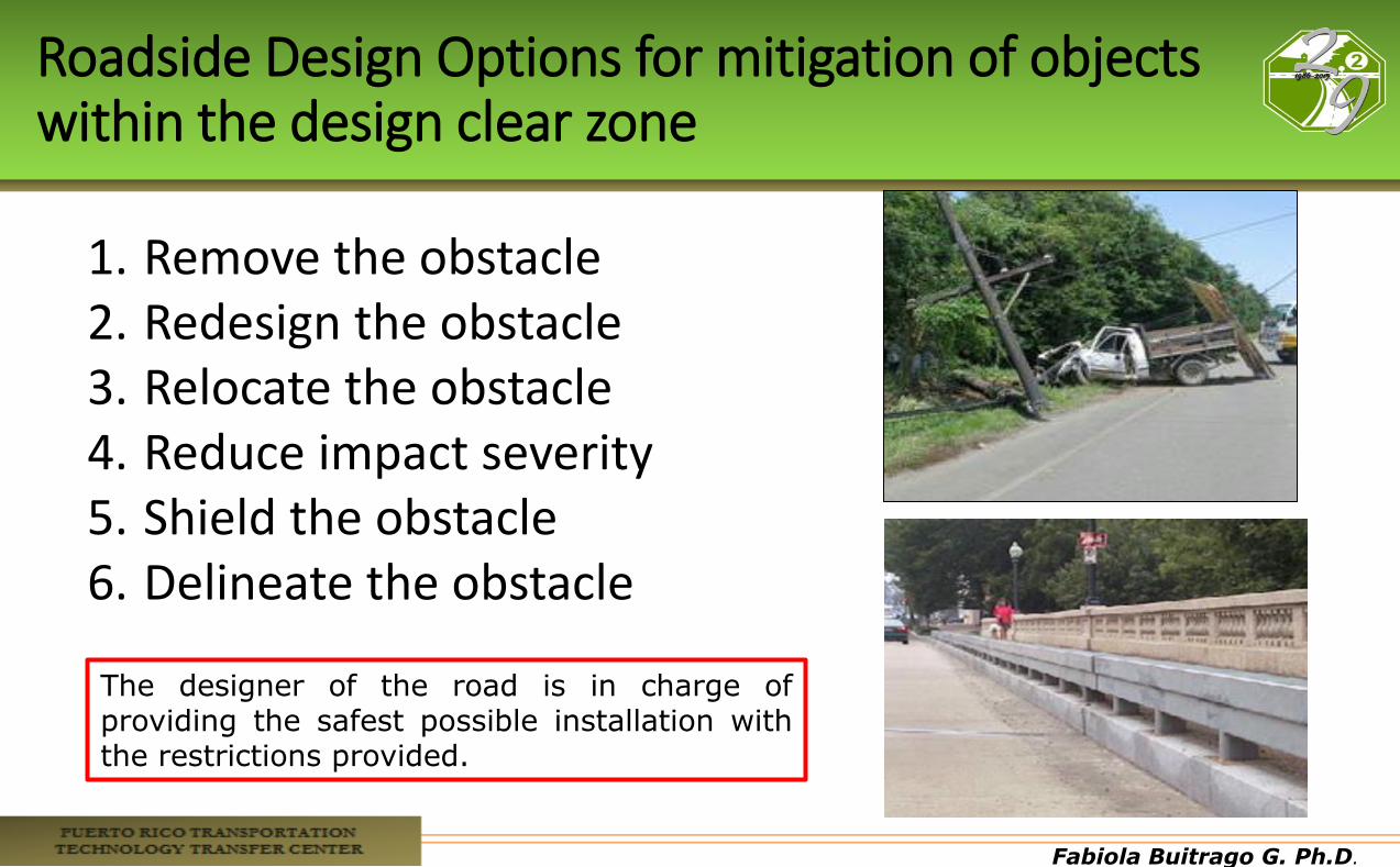
Roadside Design Options for mitigation of objects within the design clear zone
1. Remove the obstacle 2. Redesign the obstacle 3. Relocate the obstacle 4. Reduce impact severity 5. Shield the obstacle 6. Delineate the obstacle
The designer of the road is in charge of providing the safest possible installation with the restrictions provided.
Fabiola Buitrago G. Ph.D.
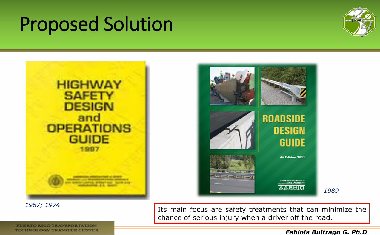
Proposed Solution
Its main focus are safety treatments that can minimize the chance of serious injury when a driver off the road.
1967; 1974
1989
Fabiola Buitrago G. Ph.D.
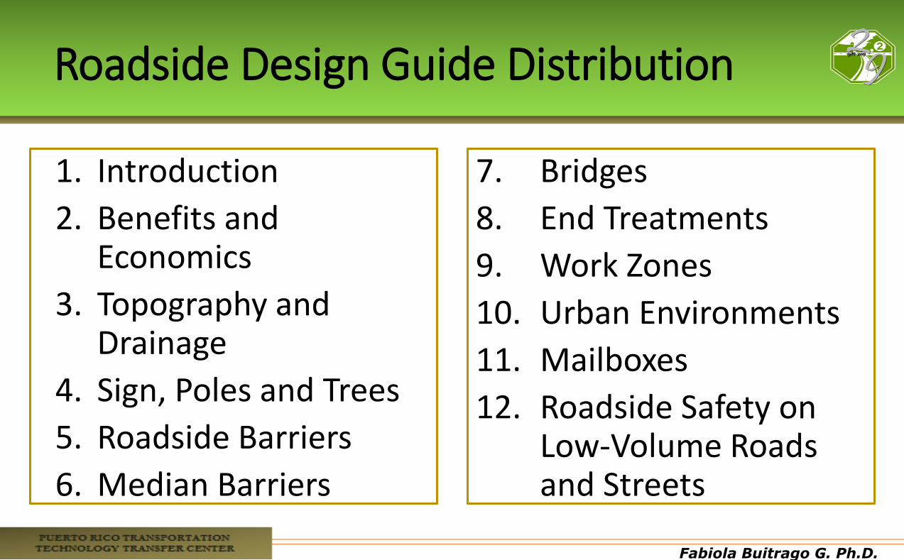
Roadside Design Guide Distribution
1. Introduction
2. Benefits and Economics
3. Topography and Drainage
4. Sign, Poles and Trees
5. Roadside Barriers
6. Median Barriers
7. Bridges
8. End Treatments
9. Work Zones
10. Urban Environments
11. Mailboxes
12. Roadside Safety on Low-Volume Roads and Streets
Fabiola Buitrago G. Ph.D.
Fabiola Buitrago G. Ph.D.
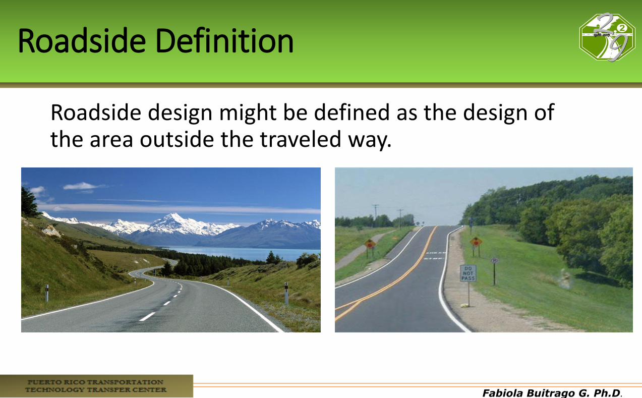
Roadside Definition
Roadside design might be defined as the design of the area outside the traveled way.
Fabiola Buitrago G. Ph.D.
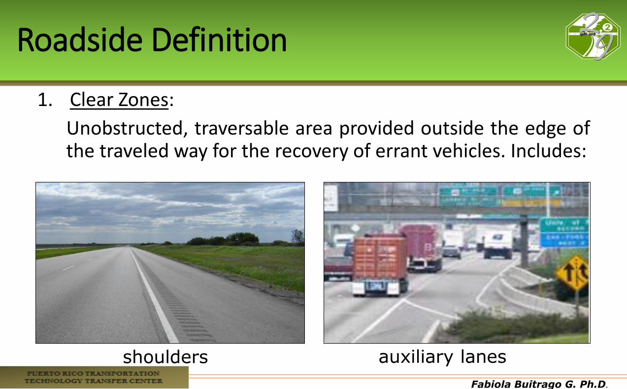
Roadside Definition
1. Clear Zones:
Unobstructed, traversable area provided outside the edge of the traveled way for the recovery of errant vehicles. Includes:
shoulders auxiliary lanes
Fabiola Buitrago G. Ph.D.
Roadside Definition(cont.)
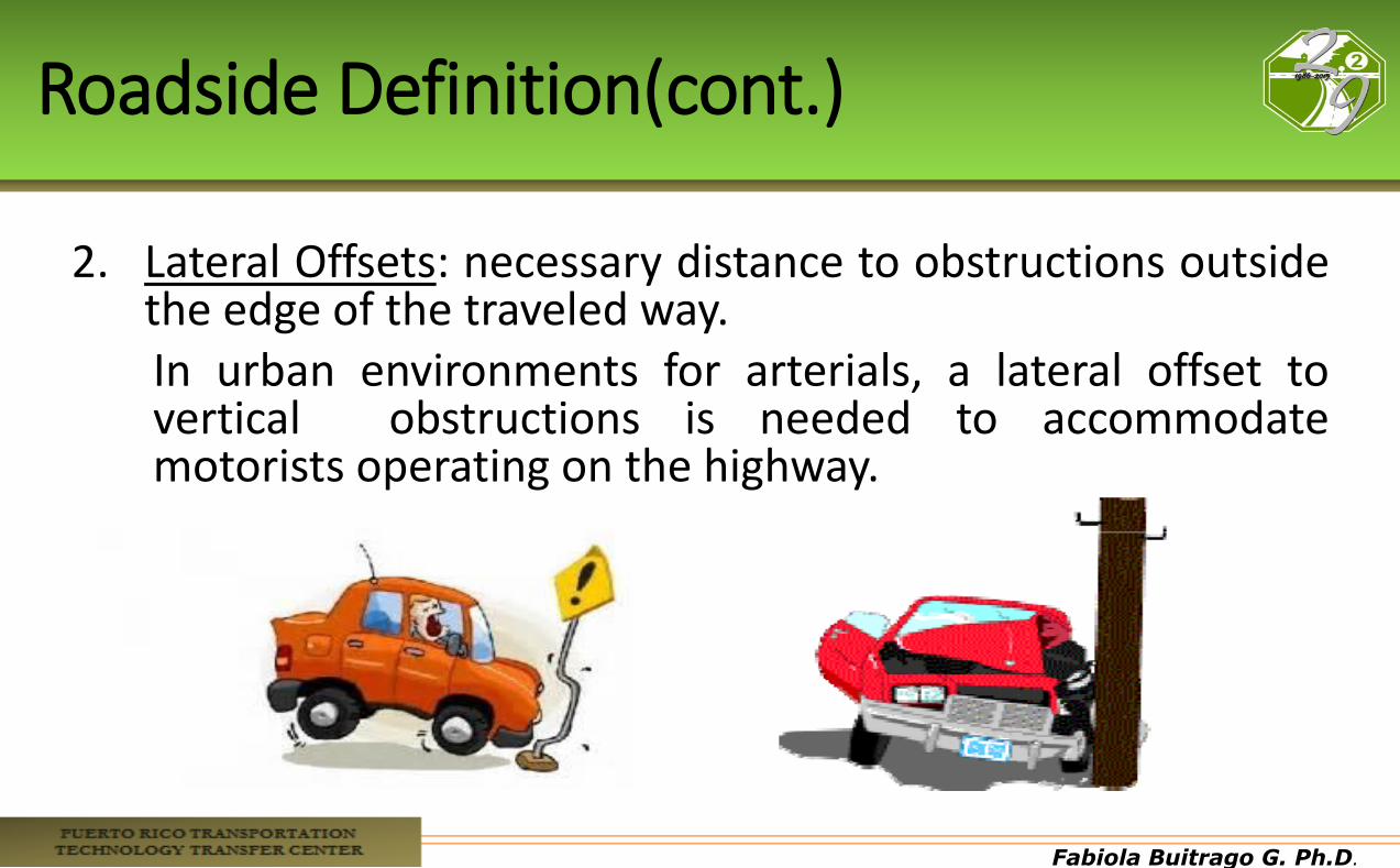
2. Lateral Offsets: necessary distance to obstructions outside the edge of the traveled way. In urban environments for arterials, a lateral offset to vertical obstructions is needed to accommodate motorists operating on the highway.
Fabiola Buitrago G. Ph.D.
Roadside Definition(cont.)
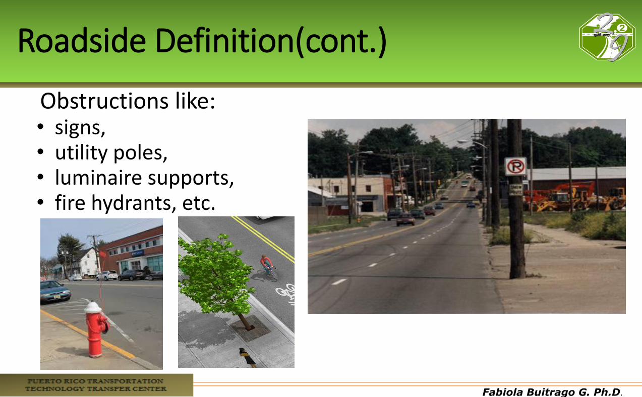
Obstructions like: • signs, • utility poles, • luminaire supports, • fire hydrants, etc.
Fabiola Buitrago G. Ph.D.
Roadside Definition(cont.)
•Lateral offset to obstructions helps to: • Avoid opposing impacts on vehicle lane position and
invasions into opposing or adjacent lanes; • Improve driveway and horizontal sight distances; • Reduce the travel lane invasions from occasional parked
and immobilized vehicles; • Improve travel lane capacity; and • Minimize contact between obstructions and vehicle
mirrors, car doors, and trucks that extend the edge when turning.
Fabiola Buitrago G. Ph.D.
Roadside Hazard
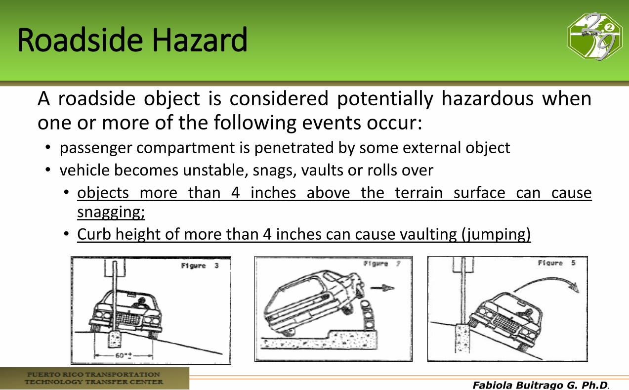
A roadside object is considered potentially hazardous when one or more of the following events occur: • passenger compartment is penetrated by some external object
• vehicle becomes unstable, snags, vaults or rolls over
• objects more than 4 inches above the terrain surface can cause snagging;
• Curb height of more than 4 inches can cause vaulting (jumping)
Fabiola Buitrago G. Ph.D.
Fabiola Buitrago G. Ph.D.
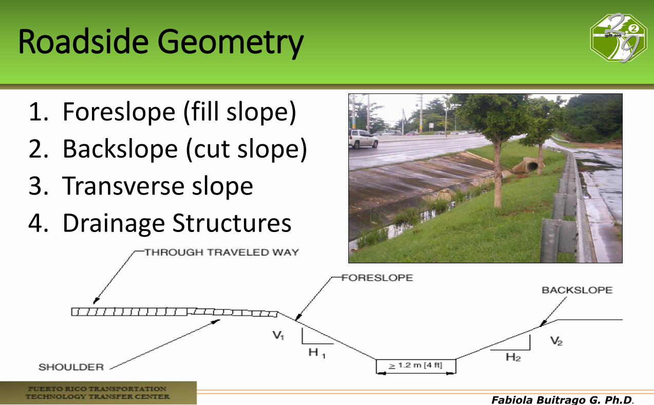
Roadside Geometry
1. Foreslope (fill slope)
2. Backslope (cut slope)
3. Transverse slope
4. Drainage Structures

Fabiola Buitrago G. Ph.D.
Roadway Geometry Features
Fabiola Buitrago G. Ph.D.
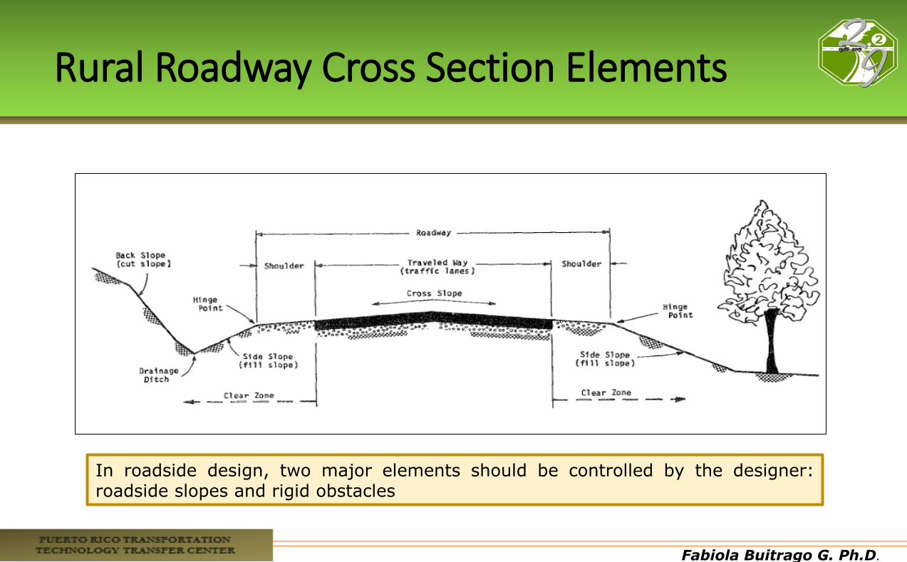
Rural Roadway Cross Section Elements
In roadside design, two major elements should be controlled by the designer: roadside slopes and rigid obstacles
Fabiola Buitrago G. Ph.D.
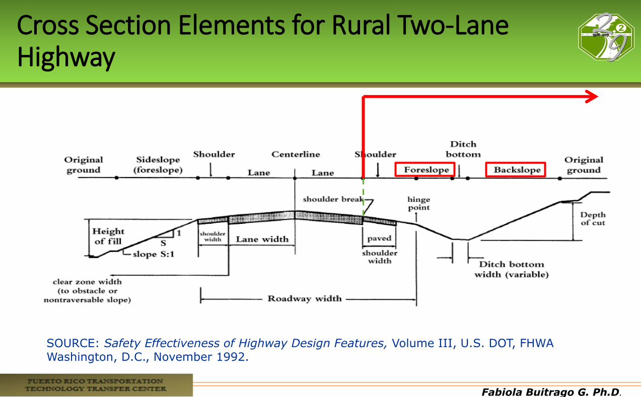
Cross Section Elements for Rural Two-Lane Highway
SOURCE: Safety Effectiveness of Highway Design Features, Volume III, U.S. DOT, FHWA Washington, D.C., November 1992.
Fabiola Buitrago G. Ph.D.
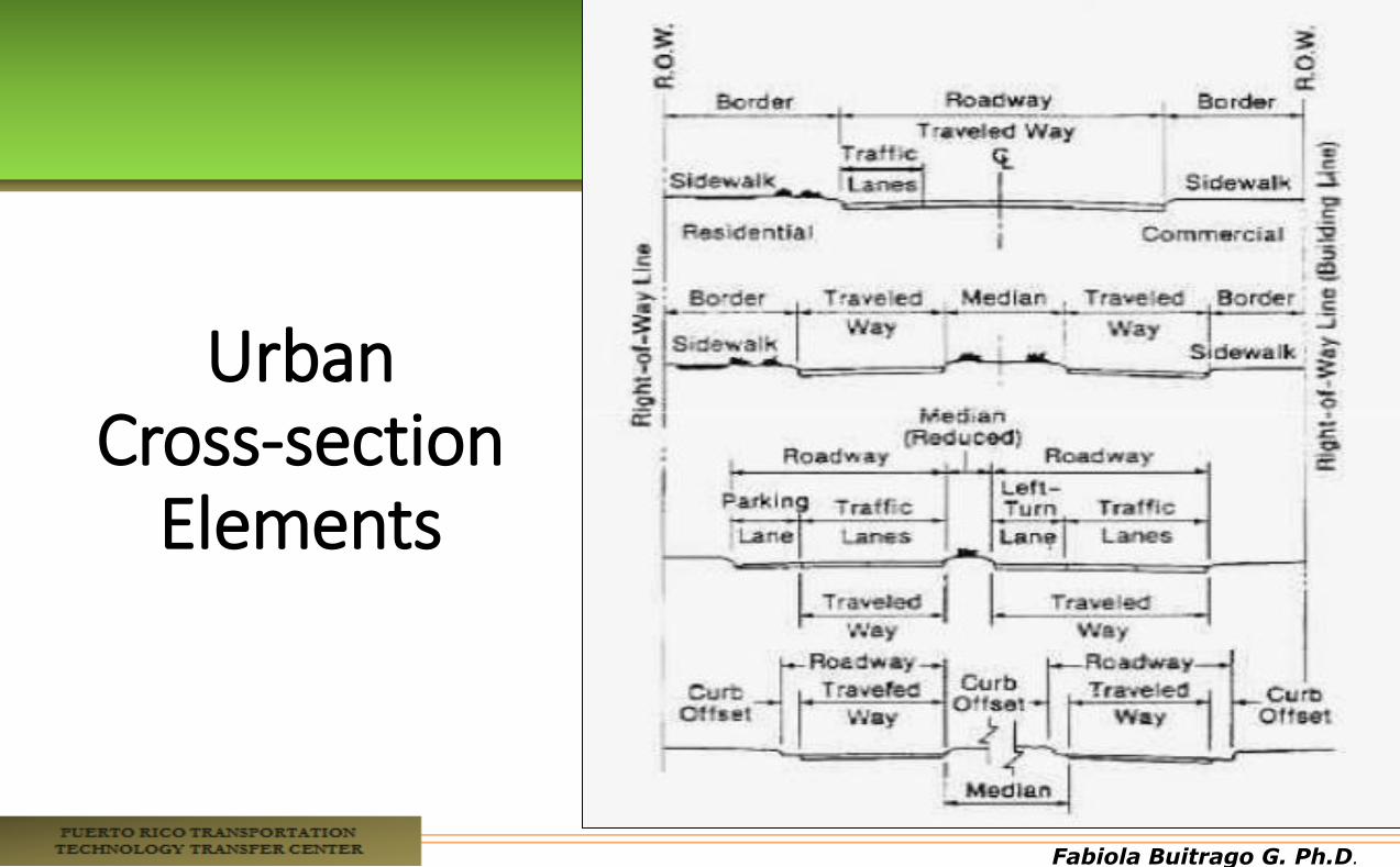
Urban Cross-section
Elements

Fabiola Buitrago G. Ph.D.
1. Steepness Categories of Foreslopes
1. Recoverable
2. Non-Recoverable
3. Critical
Fabiola Buitrago G. Ph.D.
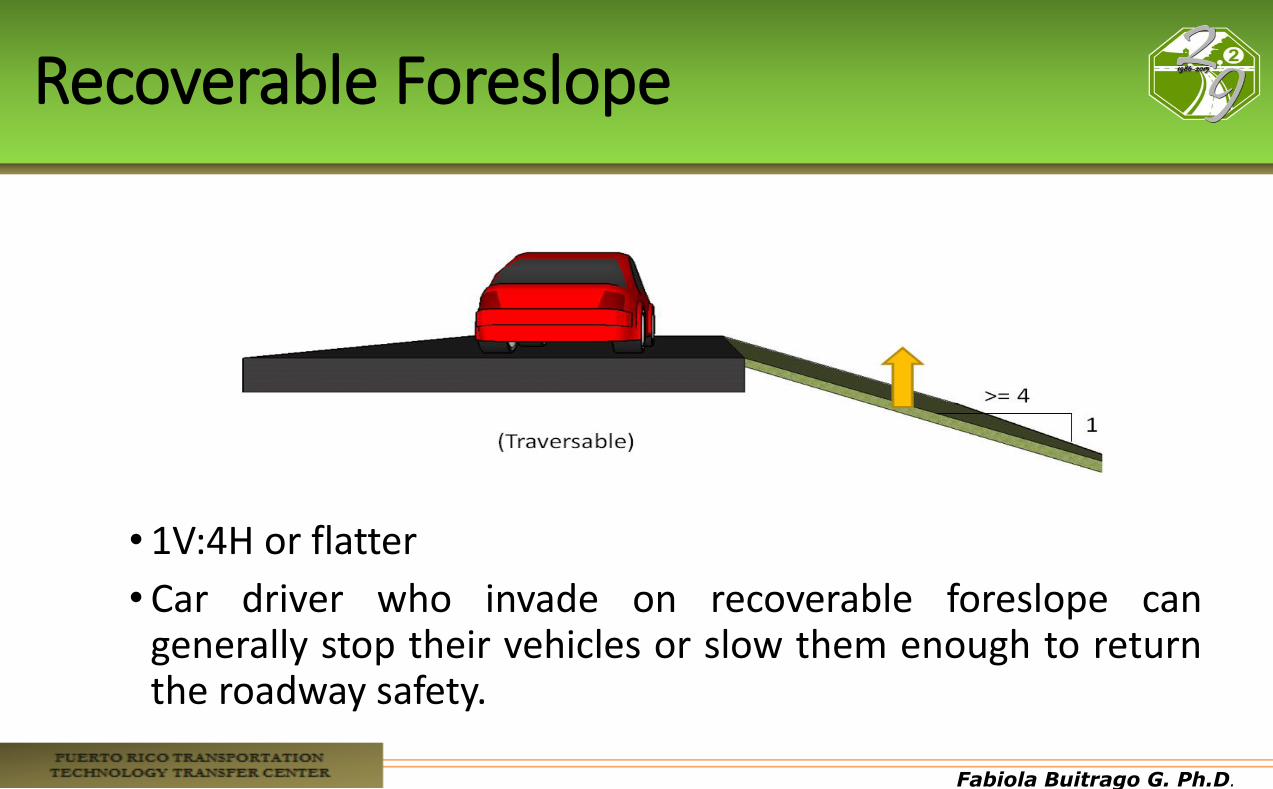
Recoverable Foreslope
• 1V:4H or flatter
• Car driver who invade on recoverable foreslope can generally stop their vehicles or slow them enough to return the roadway safety.
Fabiola Buitrago G. Ph.D.
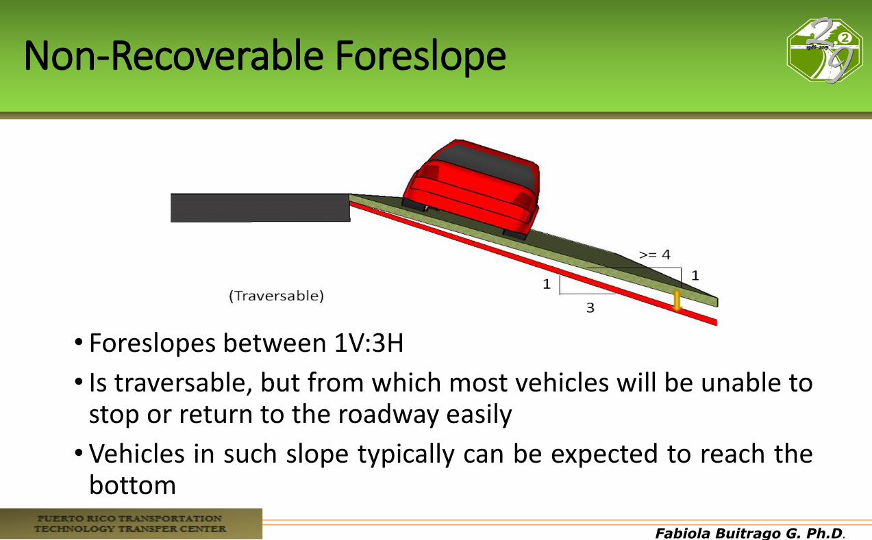
Non-Recoverable Foreslope
• Foreslopes between 1V:3H
• Is traversable, but from which most vehicles will be unable to stop or return to the roadway easily
•Vehicles in such slope typically can be expected to reach the bottom
Fabiola Buitrago G. Ph.D.
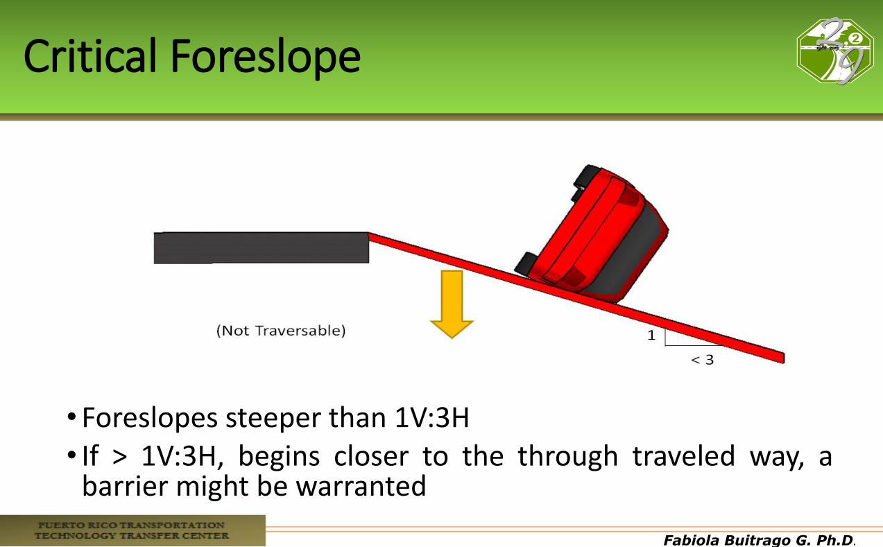
Critical Foreslope
•Foreslopes steeper than 1V:3H • If > 1V:3H, begins closer to the through traveled way, a
barrier might be warranted
Fabiola Buitrago G. Ph.D.
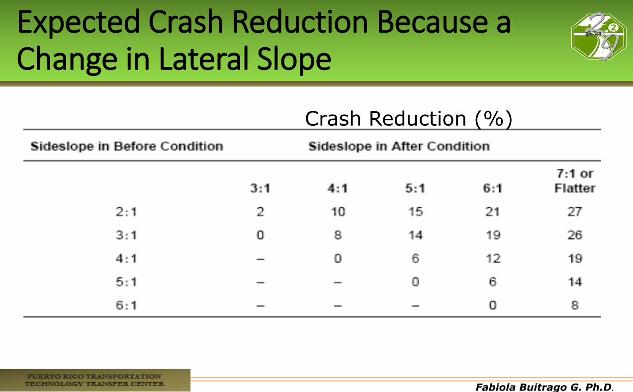
Expected Crash Reduction Because a Change in Lateral Slope
Crash Reduction (%)
Fabiola Buitrago G. Ph.D.
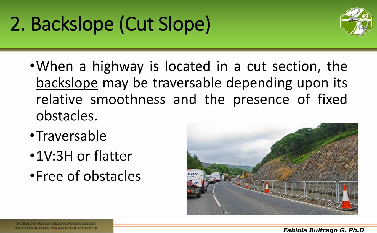
2. Backslope (Cut Slope)
•When a highway is located in a cut section, the backslope may be traversable depending upon its relative smoothness and the presence of fixed obstacles.
•Traversable
•1V:3H or flatter
•Free of obstacles
Fabiola Buitrago G. Ph.D.
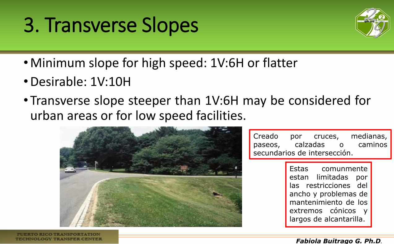
3. Transverse Slopes
•Minimum slope for high speed: 1V:6H or flatter
•Desirable: 1V:10H
•Transverse slope steeper than 1V:6H may be considered for urban areas or for low speed facilities.
Estas comunmente estan limitadas por las restricciones del ancho y problemas de mantenimiento de los extremos cónicos y largos de alcantarilla.
Creado por cruces, medianas, paseos, calzadas o caminos secundarios de intersección.
Fabiola Buitrago G. Ph.D.
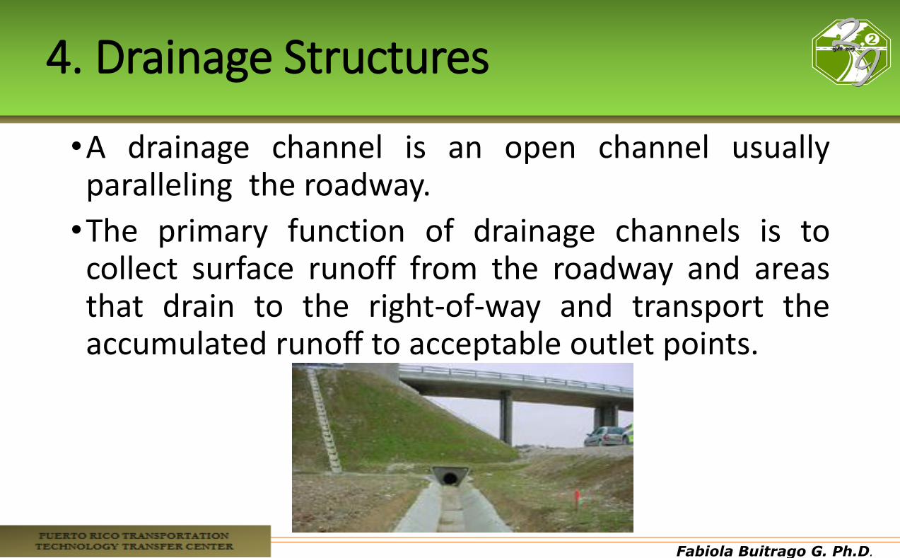
4. Drainage Structures
•A drainage channel is an open channel usually paralleling the roadway.
•The primary function of drainage channels is to collect surface runoff from the roadway and areas that drain to the right-of-way and transport the accumulated runoff to acceptable outlet points.
Fabiola Buitrago G. Ph.D.
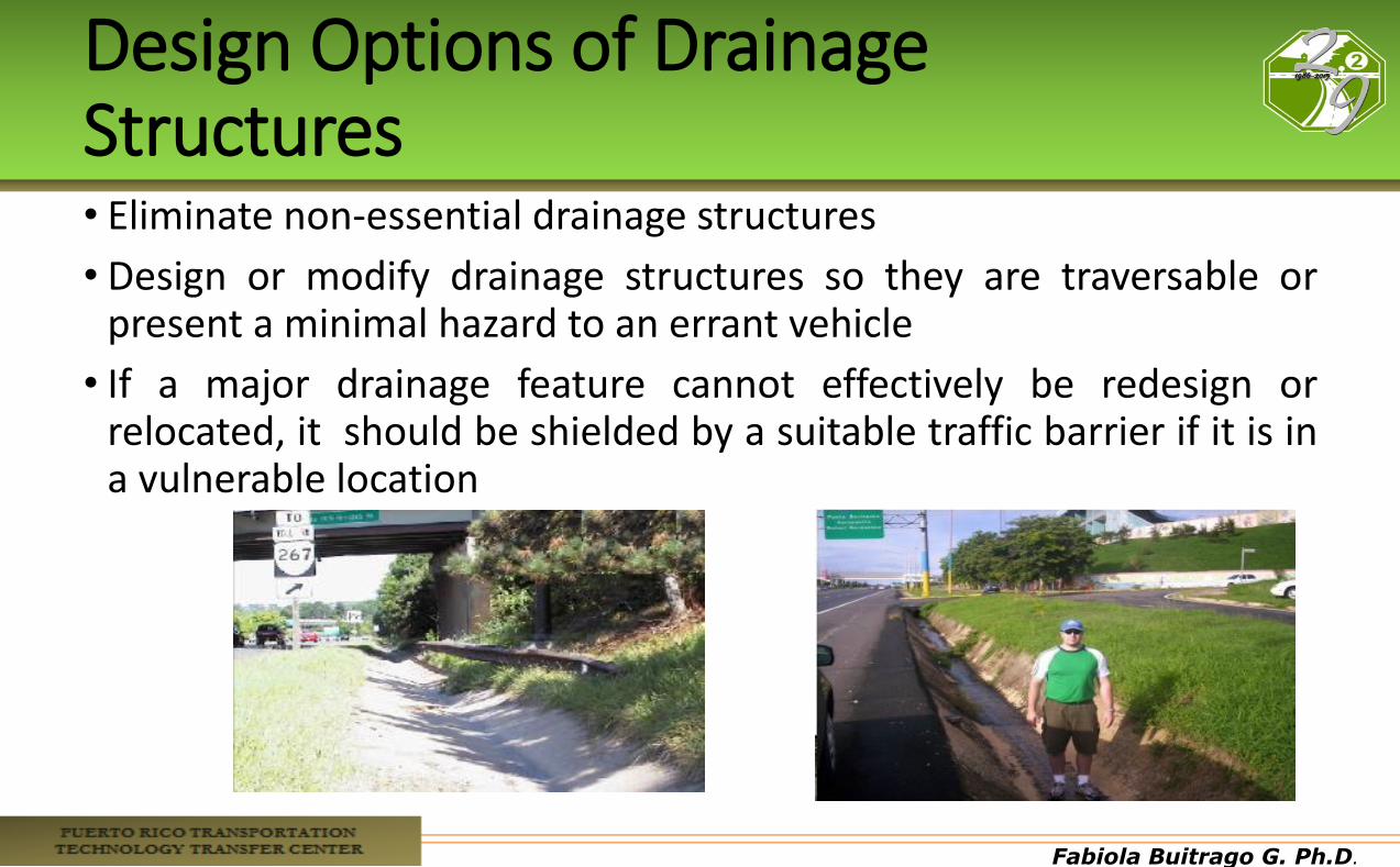
Design Options of Drainage Structures • Eliminate non-essential drainage structures
• Design or modify drainage structures so they are traversable or present a minimal hazard to an errant vehicle
• If a major drainage feature cannot effectively be redesign or relocated, it should be shielded by a suitable traffic barrier if it is in a vulnerable location
Fabiola Buitrago G. Ph.D.
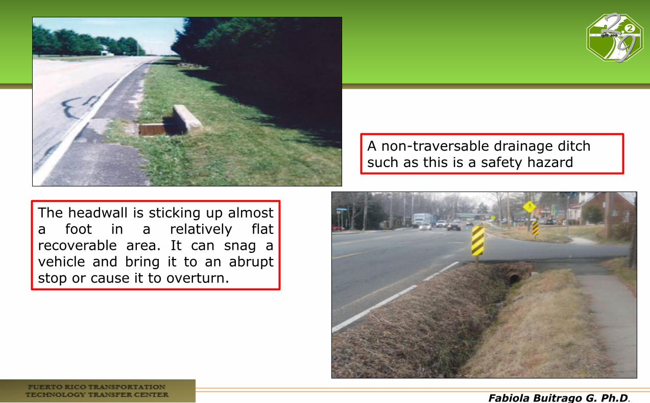
The headwall is sticking up almost a foot in a relatively flat recoverable area. It can snag a vehicle and bring it to an abrupt stop or cause it to overturn.
A non-traversable drainage ditch such as this is a safety hazard
Fabiola Buitrago G. Ph.D.
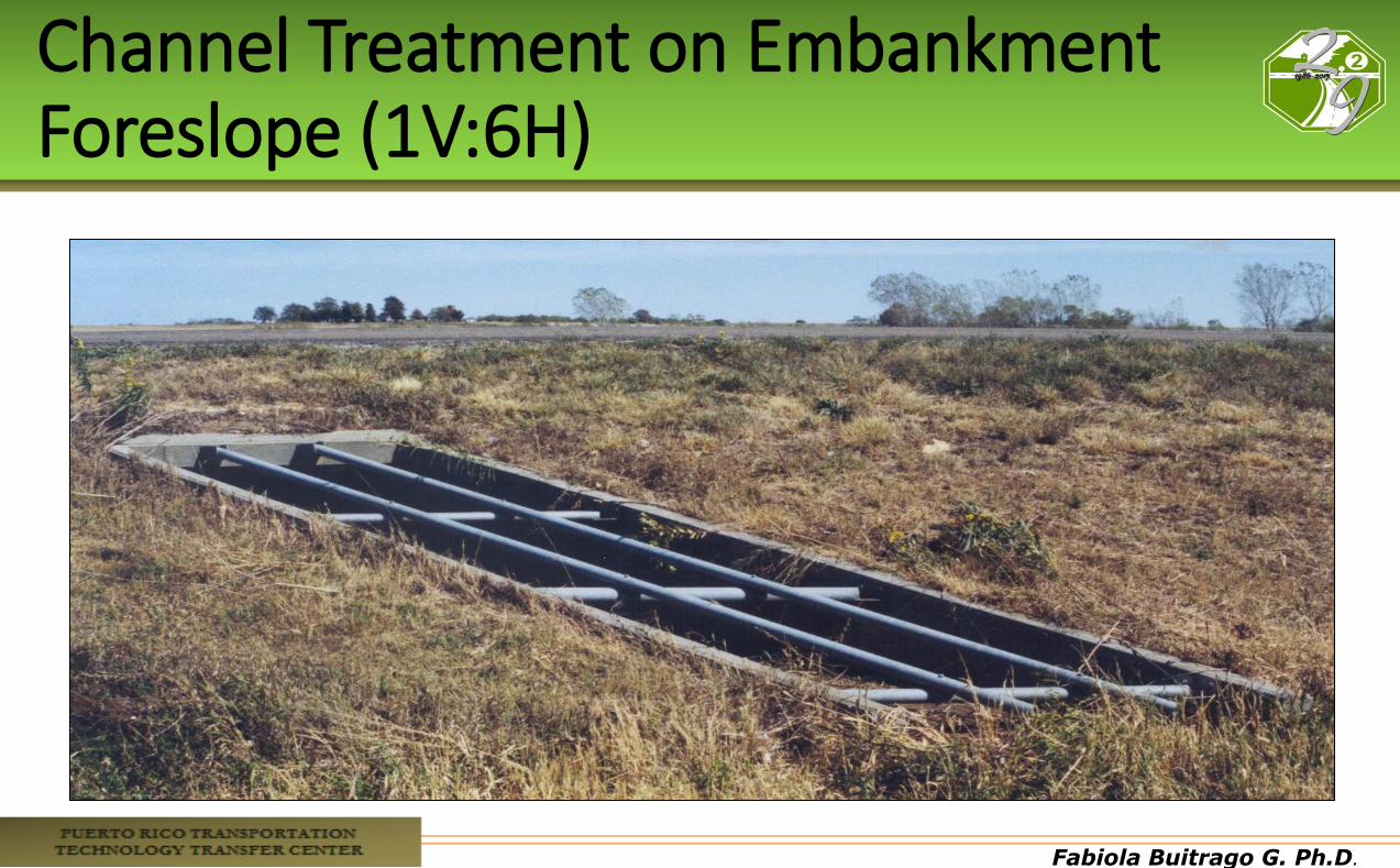
Channel Treatment on Embankment Foreslope (1V:6H)
Fabiola Buitrago G. Ph.D.
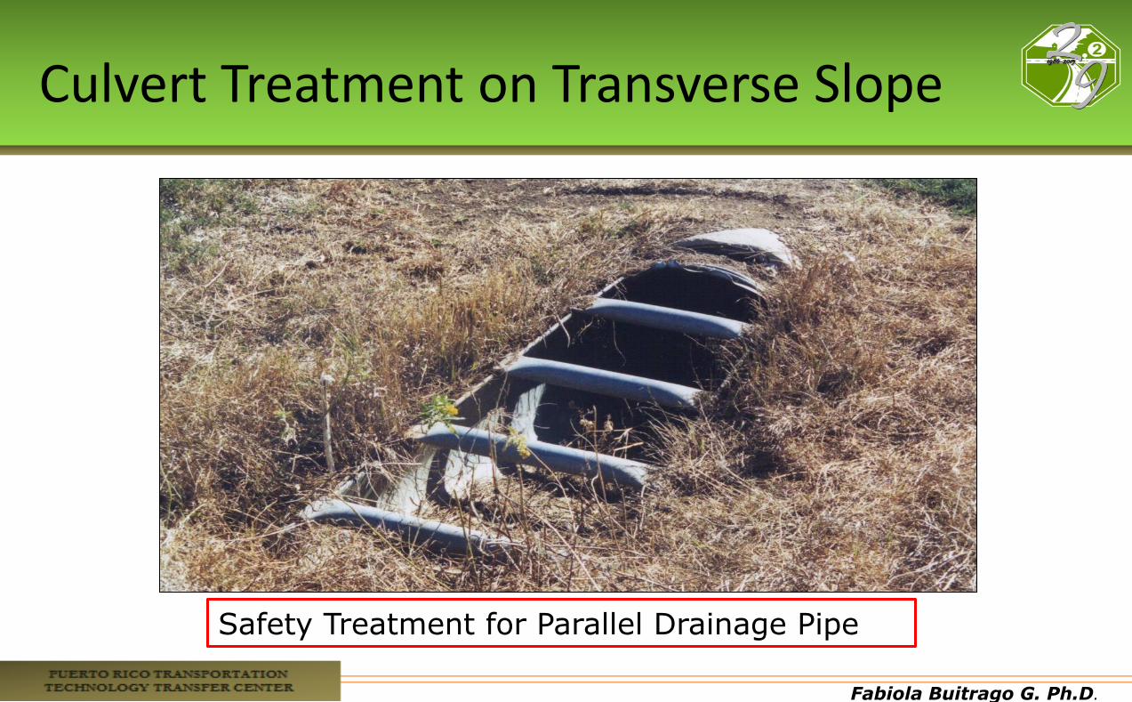
Culvert Treatment on Transverse Slope
Safety Treatment for Parallel Drainage Pipe
Fabiola Buitrago G. Ph.D.
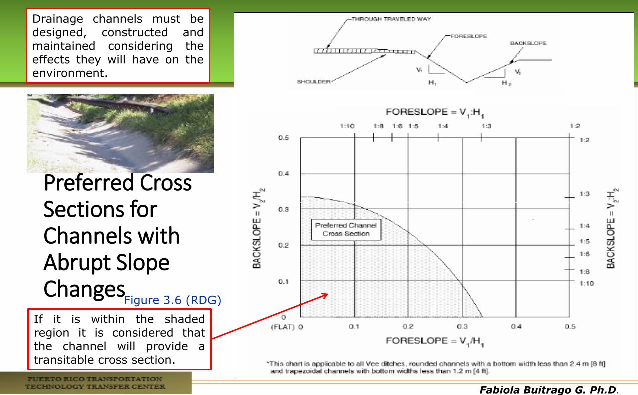
Preferred Cross Sections for Channels with Abrupt Slope Changes
Figure 3.6 (RDG)
If it is within the shaded region it is considered that the channel will provide a transitable cross section.
Drainage channels must be designed, constructed and maintained considering the effects they will have on the environment.
Fabiola Buitrago G. Ph.D.
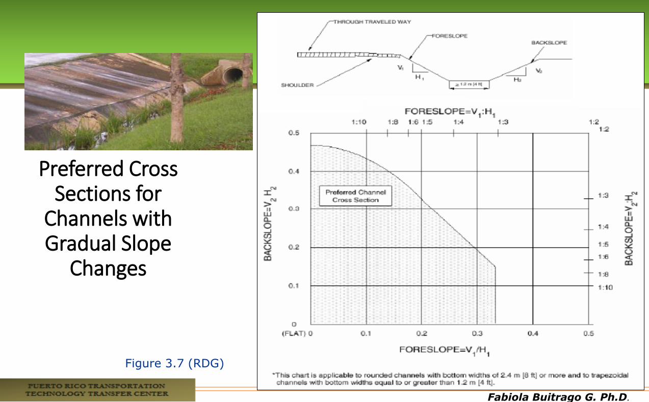
Preferred Cross Sections for
Channels with Gradual Slope
Changes
Figure 3.7 (RDG)
Fabiola Buitrago G. Ph.D.
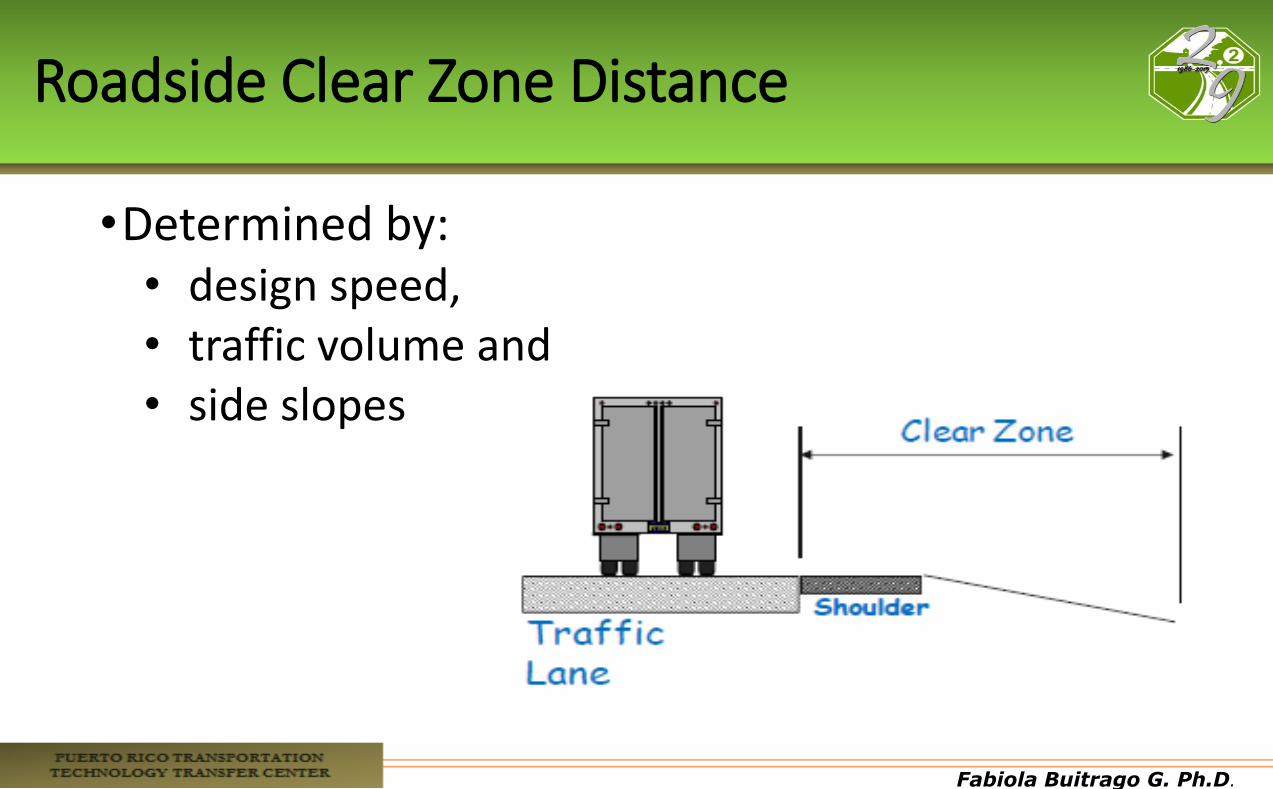
Roadside Clear Zone Distance
•Determined by: • design speed, • traffic volume and • side slopes
Fabiola Buitrago G. Ph.D.
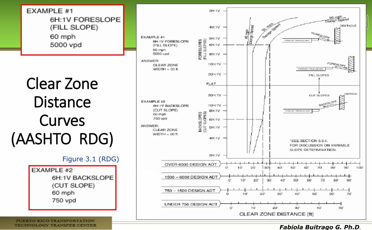
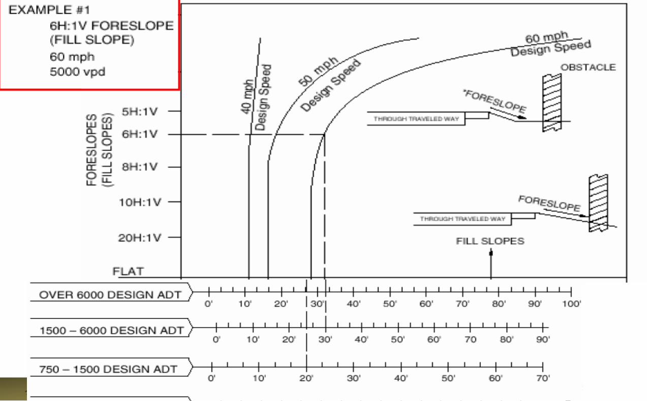
Clear Zone Distance Curves
(AASHTO RDG) Figure 3.1 (RDG)
Fabiola Buitrago G. Ph.D.
Fabiola Buitrago G. Ph.D.
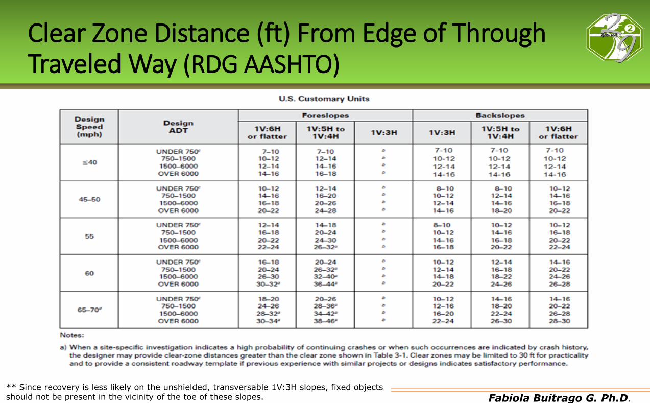
Clear Zone Distance (ft) From Edge of Through Traveled Way (RDG AASHTO)
** Since recovery is less likely on the unshielded, transversable 1V:3H slopes, fixed objects should not be present in the vicinity of the toe of these slopes.
Fabiola Buitrago G. Ph.D.
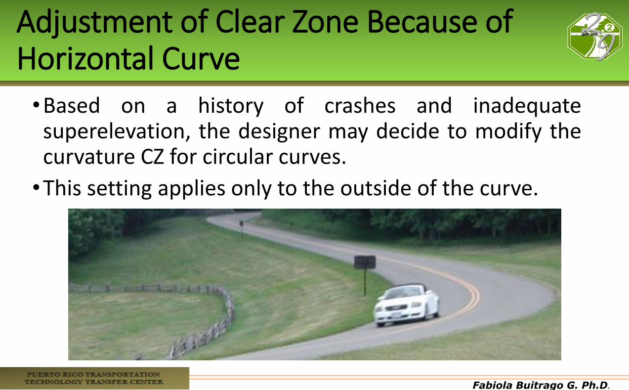
Adjustment of Clear Zone Because of Horizontal Curve
•Based on a history of crashes and inadequate superelevation, the designer may decide to modify the curvature CZ for circular curves.
•This setting applies only to the outside of the curve.
Fabiola Buitrago G. Ph.D.
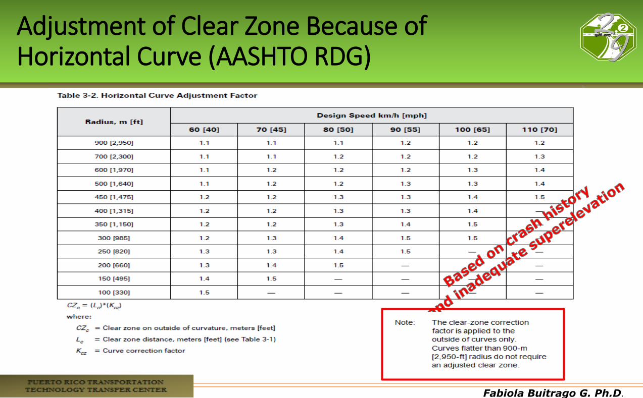
Adjustment of Clear Zone Because of Horizontal Curve (AASHTO RDG)
Fabiola Buitrago G. Ph.D.
Review
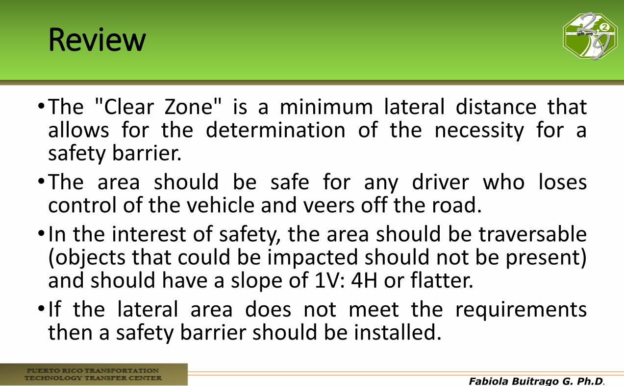
•The "Clear Zone" is a minimum lateral distance that allows for the determination of the necessity for a safety barrier. •The area should be safe for any driver who loses control of the vehicle and veers off the road. • In the interest of safety, the area should be traversable (objects that could be impacted should not be present) and should have a slope of 1V: 4H or flatter. • If the lateral area does not meet the requirements then a safety barrier should be installed.

Fabiola Buitrago G. Ph.D.
Fabiola Buitrago G. Ph.D.
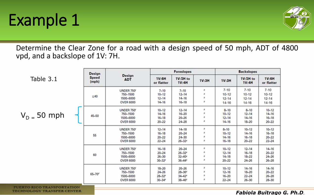
Example 1
Determine the Clear Zone for a road with a design speed of 50 mph, ADT of 4800 vpd, and a backslope of 1V: 7H.
VD = 50 mph
Table 3.1
Fabiola Buitrago G. Ph.D.
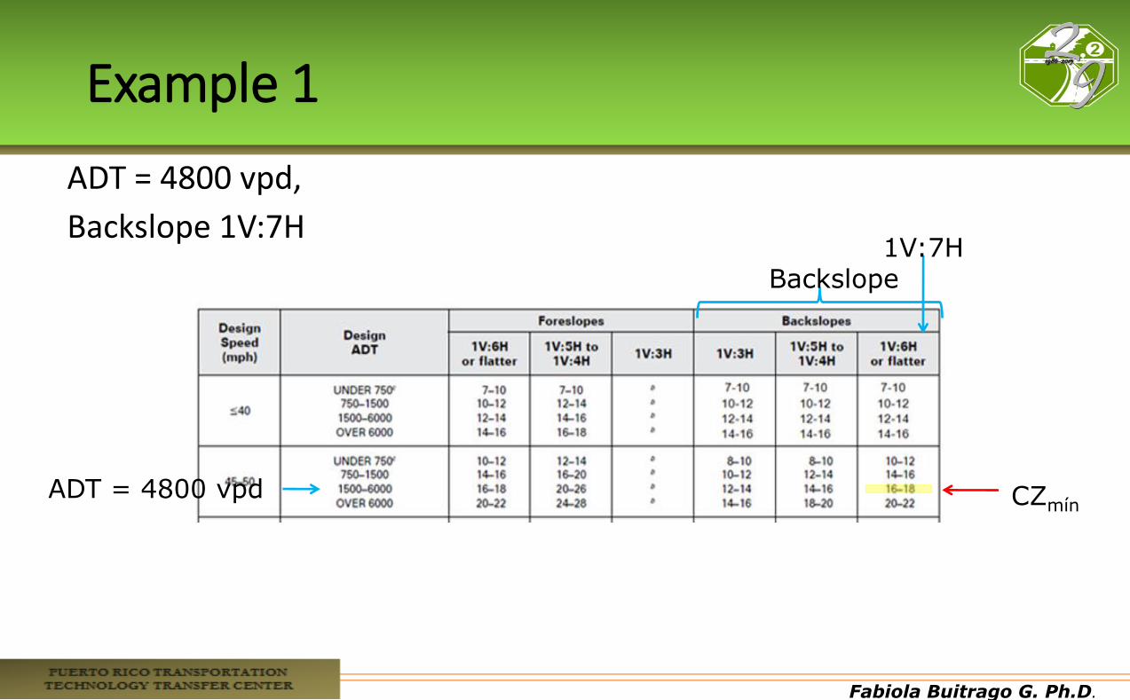
Example 1
ADT = 4800 vpd,
Backslope 1V:7H
Backslope
ADT = 4800 vpd
1V:7H
CZmín
Fabiola Buitrago G. Ph.D.
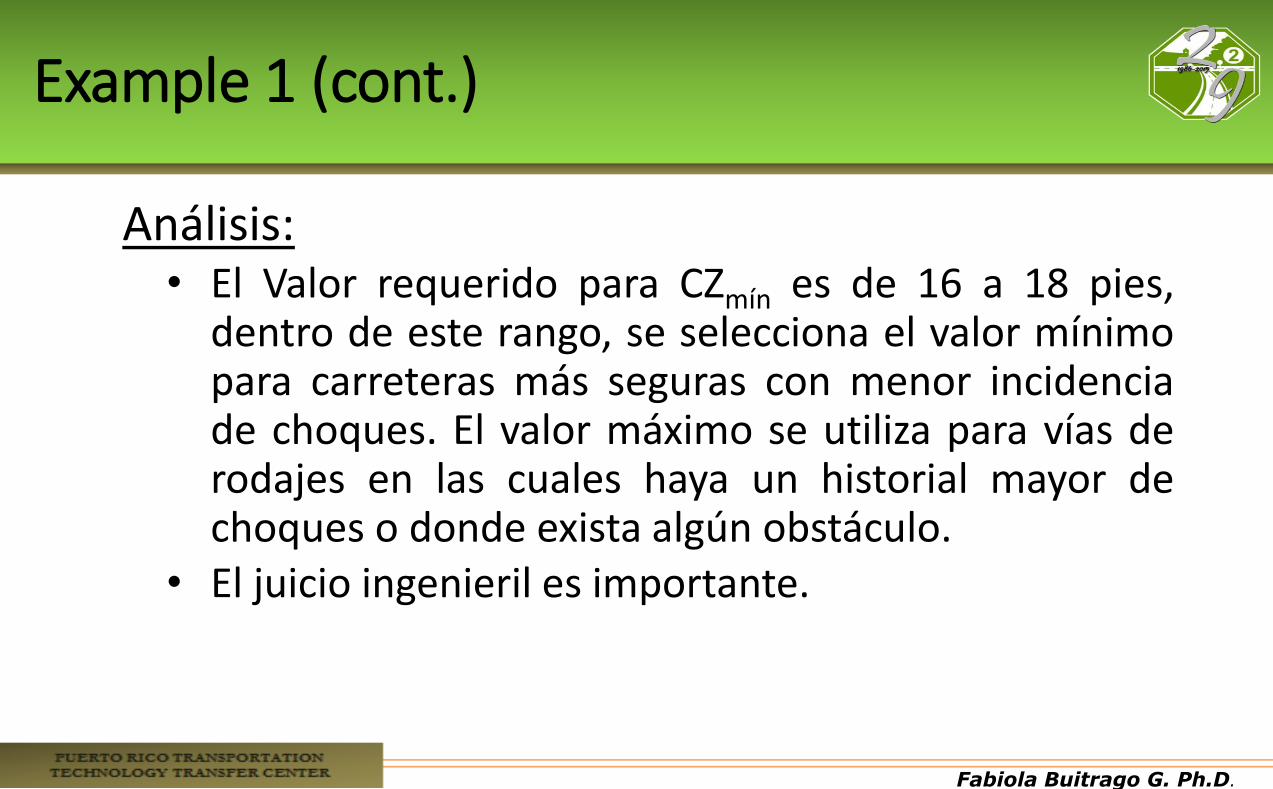
Example 1 (cont.)
Análisis: • El Valor requerido para CZmín es de 16 a 18 pies,
dentro de este rango, se selecciona el valor mínimo para carreteras más seguras con menor incidencia de choques. El valor máximo se utiliza para vías de rodajes en las cuales haya un historial mayor de choques o donde exista algún obstáculo.
• El juicio ingenieril es importante.
Fabiola Buitrago G. Ph.D.
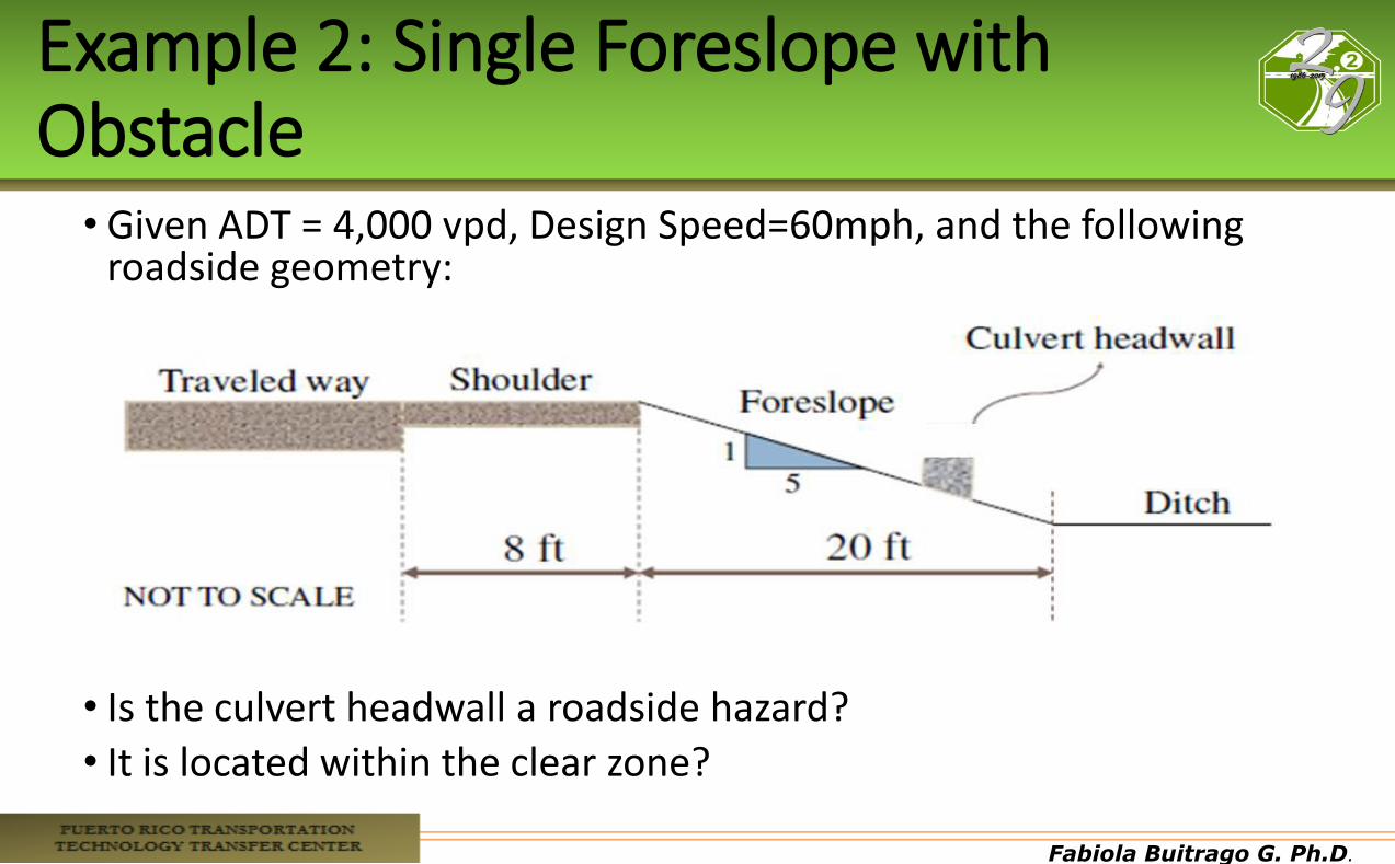
Example 2: Single Foreslope with Obstacle
• Given ADT = 4,000 vpd, Design Speed=60mph, and the following roadside geometry:
• Is the culvert headwall a roadside hazard?
• It is located within the clear zone?
Fabiola Buitrago G. Ph.D.
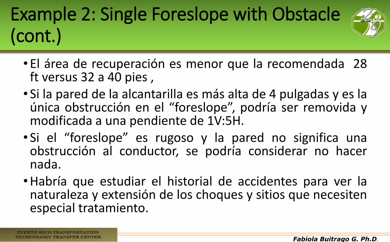
Example 2: Single Foreslope with Obstacle (cont.)
•El área de recuperación es menor que la recomendada 28 ft versus 32 a 40 pies , •Si la pared de la alcantarilla es más alta de 4 pulgadas y es la
única obstrucción en el “foreslope”, podría ser removida y modificada a una pendiente de 1V:5H. •Si el “foreslope” es rugoso y la pared no significa una
obstrucción al conductor, se podría considerar no hacer nada. •Habría que estudiar el historial de accidentes para ver la
naturaleza y extensión de los choques y sitios que necesiten especial tratamiento.
Fabiola Buitrago G. Ph.D.
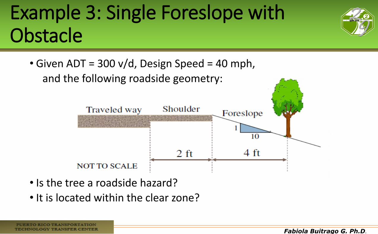
Example 3: Single Foreslope with Obstacle
• Given ADT = 300 v/d, Design Speed = 40 mph,
and the following roadside geometry:
• Is the tree a roadside hazard?
• It is located within the clear zone?
Fabiola Buitrago G. Ph.D.
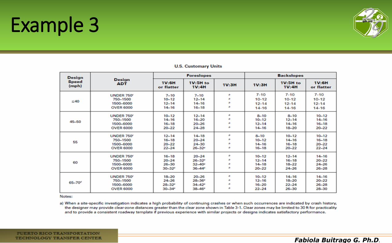
Example 3
Fabiola Buitrago G. Ph.D.
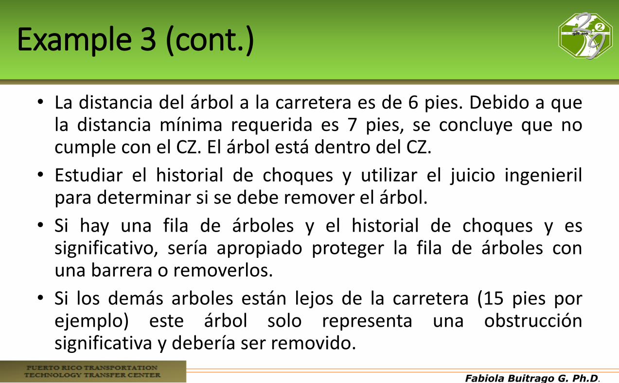
Example 3 (cont.)
• La distancia del árbol a la carretera es de 6 pies. Debido a que la distancia mínima requerida es 7 pies, se concluye que no cumple con el CZ. El árbol está dentro del CZ.
• Estudiar el historial de choques y utilizar el juicio ingenieril para determinar si se debe remover el árbol.
• Si hay una fila de árboles y el historial de choques y es significativo, sería apropiado proteger la fila de árboles con una barrera o removerlos.
• Si los demás arboles están lejos de la carretera (15 pies por ejemplo) este árbol solo representa una obstrucción significativa y debería ser removido.
Fabiola Buitrago G. Ph.D.
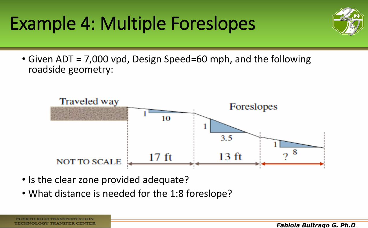
Example 4: Multiple Foreslopes
• Given ADT = 7,000 vpd, Design Speed=60 mph, and the following roadside geometry:
• Is the clear zone provided adequate?
• What distance is needed for the 1:8 foreslope?
Fabiola Buitrago G. Ph.D.
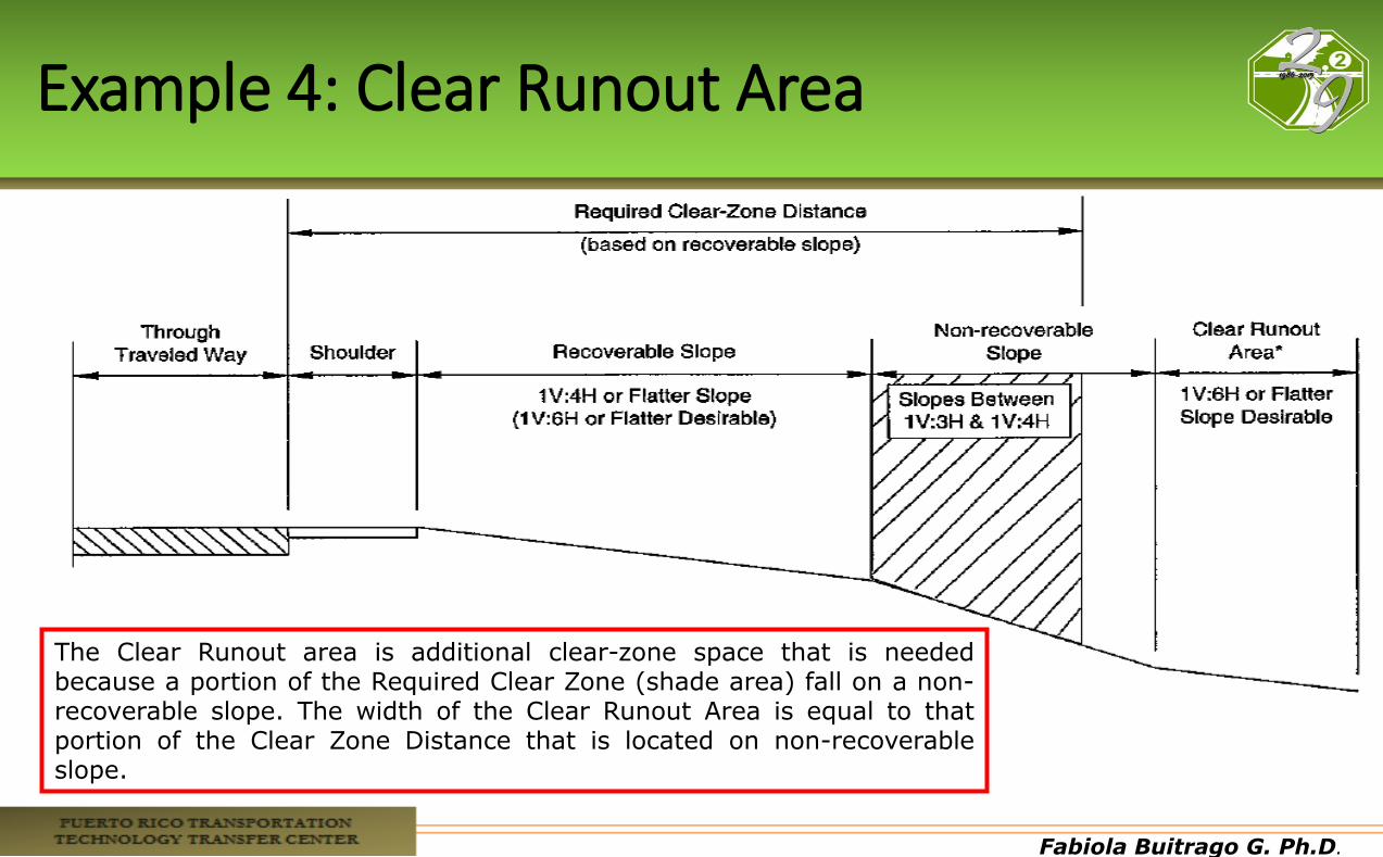
Example 4: Clear Runout Area
The Clear Runout area is additional clear-zone space that is needed because a portion of the Required Clear Zone (shade area) fall on a non-recoverable slope. The width of the Clear Runout Area is equal to that portion of the Clear Zone Distance that is located on non-recoverable slope.
Fabiola Buitrago G. Ph.D.
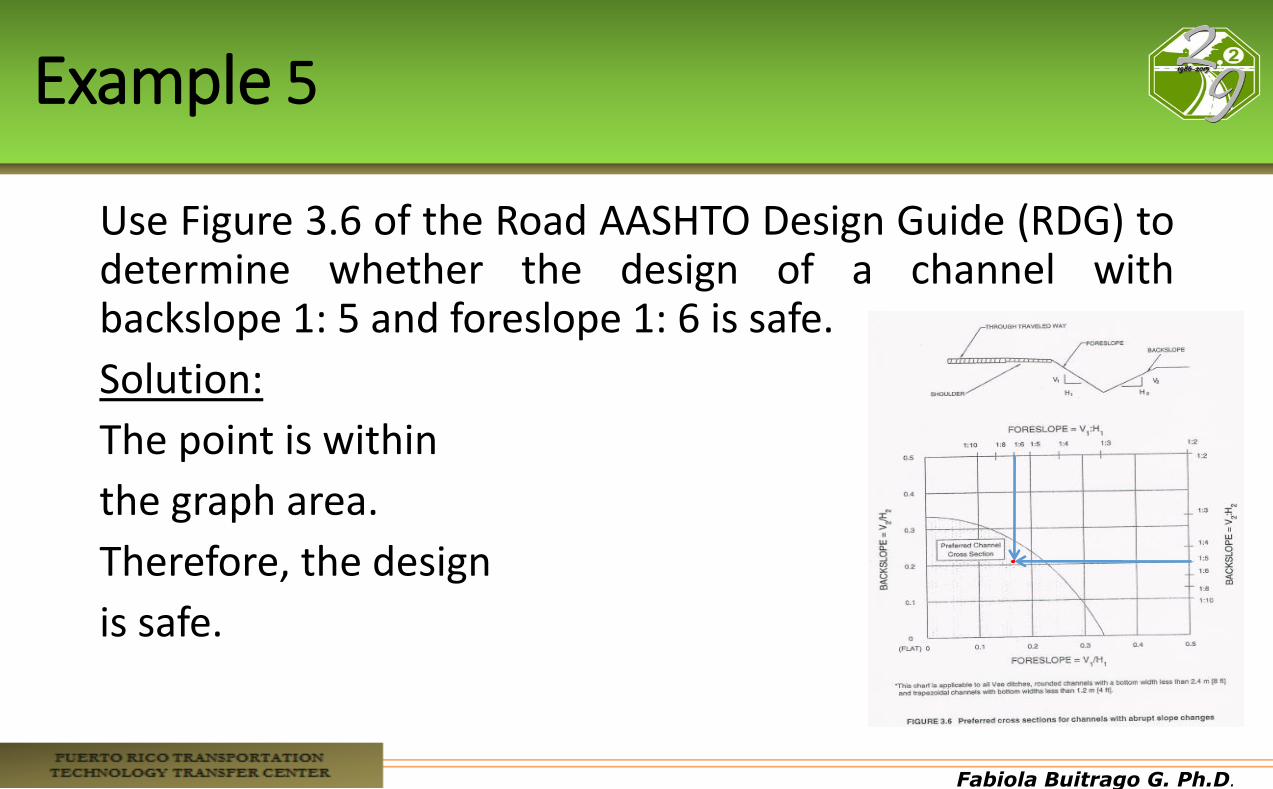
Example 5
Use Figure 3.6 of the Road AASHTO Design Guide (RDG) to determine whether the design of a channel with backslope 1: 5 and foreslope 1: 6 is safe.
Solution:
The point is within
the graph area.
Therefore, the design
is safe.
Fabiola Buitrago G. Ph.D.
Sign, Signal, and Luminaire Supports, Utility Poles, Trees
Fabiola Buitrago G. Ph.D.
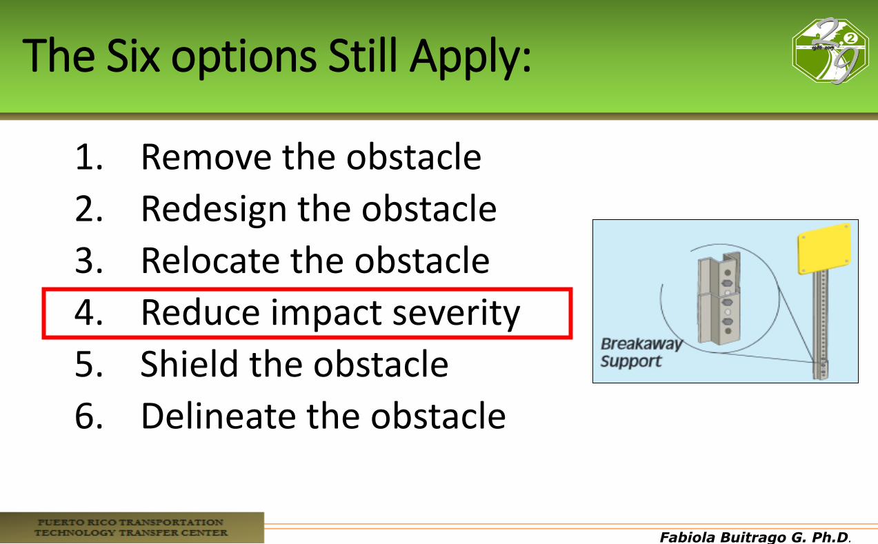
The Six options Still Apply:
1. Remove the obstacle
2. Redesign the obstacle
3. Relocate the obstacle
4. Reduce impact severity
5. Shield the obstacle
6. Delineate the obstacle
Fabiola Buitrago G. Ph.D.
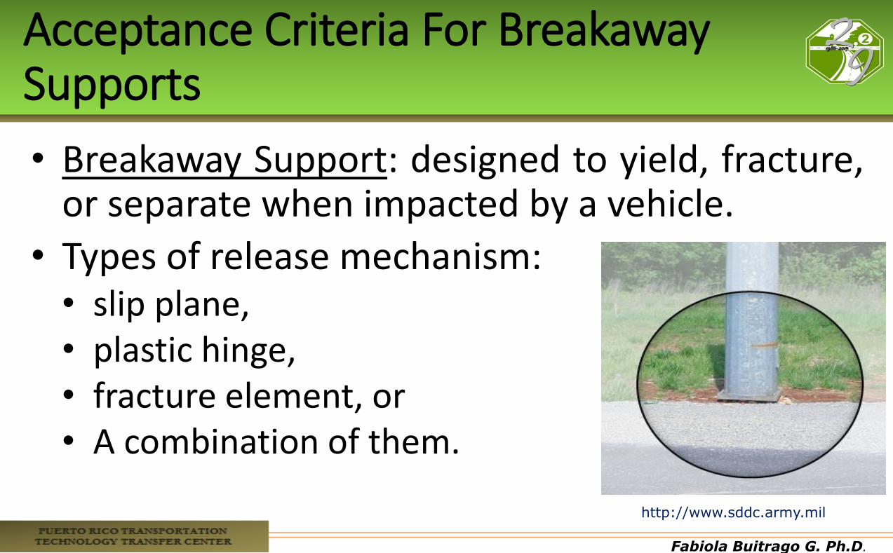
Acceptance Criteria For Breakaway Supports
• Breakaway Support: designed to yield, fracture, or separate when impacted by a vehicle.
• Types of release mechanism: • slip plane, • plastic hinge, • fracture element, or • A combination of them.
http://www.sddc.army.mil
Fabiola Buitrago G. Ph.D.
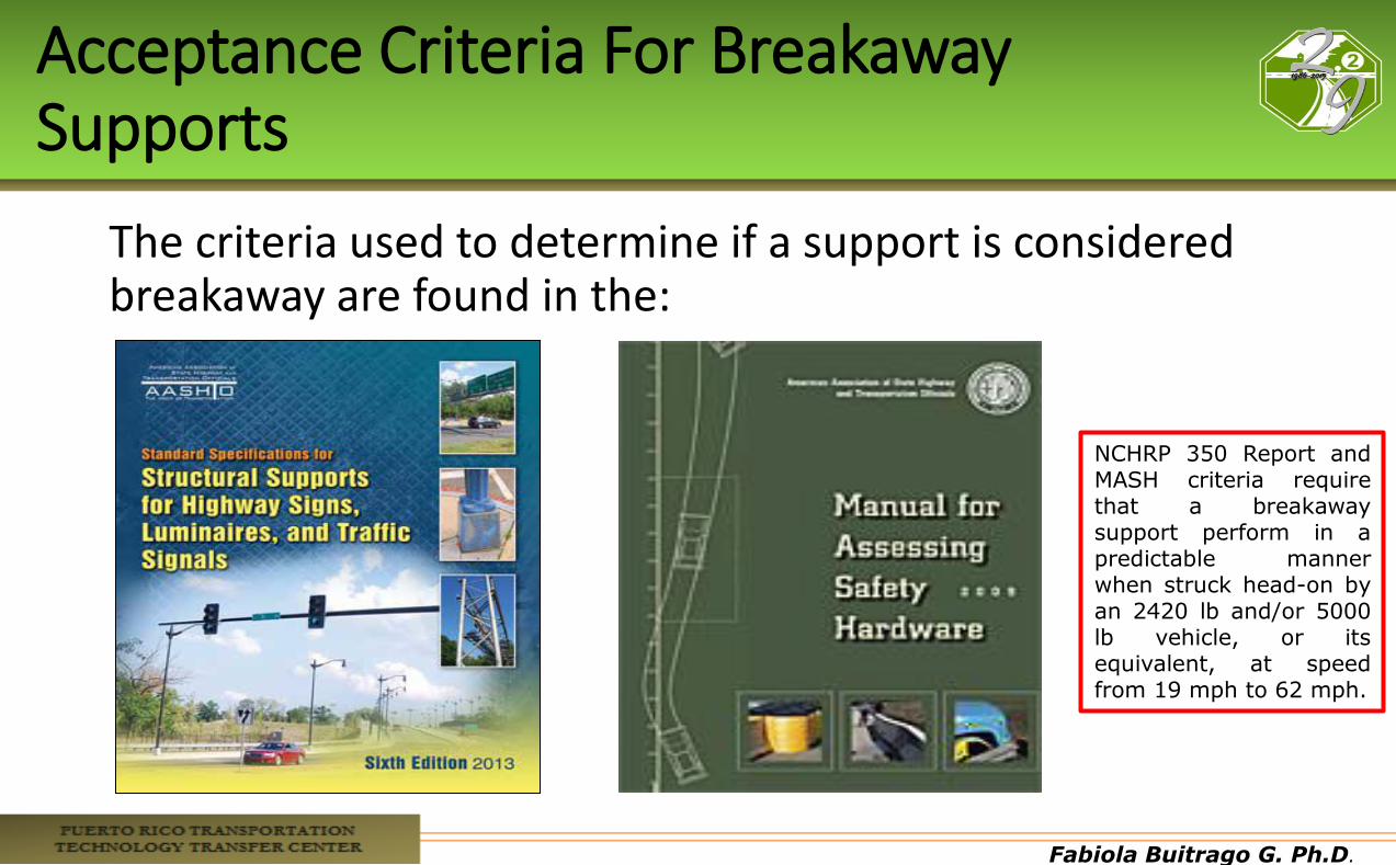
Acceptance Criteria For Breakaway Supports
The criteria used to determine if a support is considered breakaway are found in the:
NCHRP 350 Report and MASH criteria require that a breakaway support perform in a predictable manner when struck head-on by an 2420 lb and/or 5000 lb vehicle, or its equivalent, at speed from 19 mph to 62 mph.
Fabiola Buitrago G. Ph.D.
Design and Location Criteria
• Sign, luminaire, and other supports should be: • structurally adequate to support the device mounted
on them • structurally adequate to resist ice and wind loads
• MUTCD states that if located in the clear zone – it should be shielded or breakaway
Fabiola Buitrago G. Ph.D.
Design and Location Criteria
•Sign, luminaire, and other supports : • Should not be placed where they are going to get
damaged, such as ditches (erosion) • If is not needed, remove it • If needed, place it where is less likely to be hit • Place it behind a barrier or on an existing structure • If not, make it breakaway
Fabiola Buitrago G. Ph.D.
Design and Location Criteria
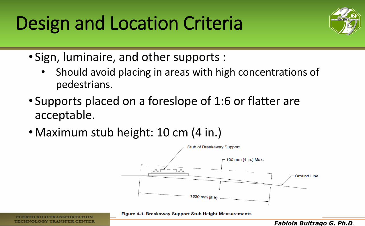
•Sign, luminaire, and other supports : • Should avoid placing in areas with high concentrations of
pedestrians.
•Supports placed on a foreslope of 1:6 or flatter are acceptable.
•Maximum stub height: 10 cm (4 in.)
Fabiola Buitrago G. Ph.D.
Design and Location Criteria
Sign, luminaire, and other supports: • If electrical:
• Must have electrical disconnects to reduce the risk of fire and electrical hazards
• It should disconnect as close to the pole base as possible
• Designed to be impacted at bumper height • Not located in places near ditches, on steep slopes
where a vehicle can airborne at the time of impact • Type of soil can also affect the mechanism some
support might be sensitive to foundation movement
Fabiola Buitrago G. Ph.D.
Sign Supports
• Roadway signs can be divided into three main categories: • Overhead signs • Large roadside signs • Small roadside signs
Fabiola Buitrago G. Ph.D.
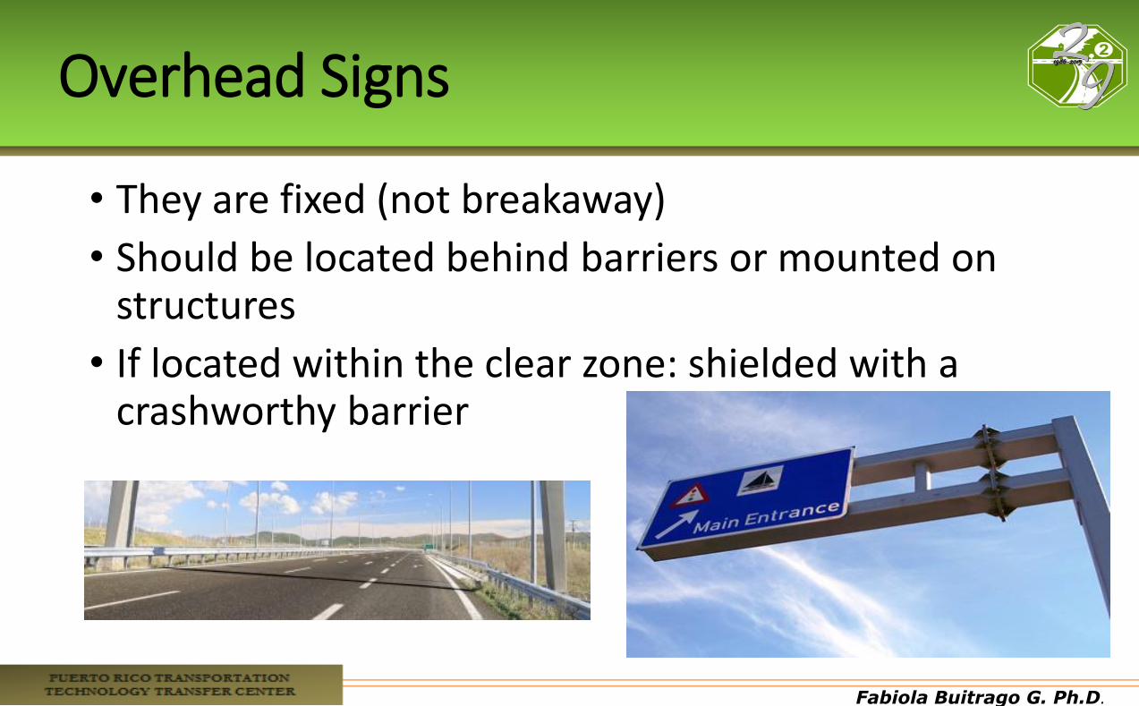
Overhead Signs
• They are fixed (not breakaway)
• Should be located behind barriers or mounted on structures
• If located within the clear zone: shielded with a crashworthy barrier

Fabiola Buitrago G. Ph.D.
Overhead Signs
Source:www.interstate-guide.com
Fabiola Buitrago G. Ph.D.
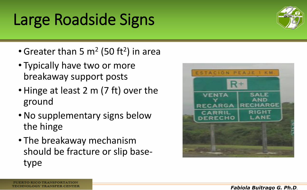
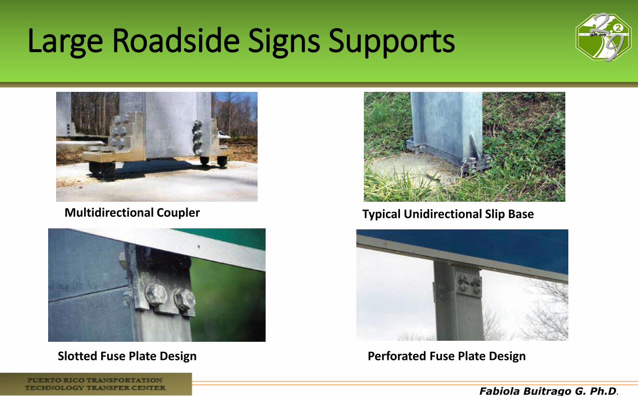
Large Roadside Signs
•Greater than 5 m2 (50 ft2) in area
• Typically have two or more breakaway support posts
•Hinge at least 2 m (7 ft) over the ground
•No supplementary signs below the hinge
• The breakaway mechanism should be fracture or slip base-type
Fabiola Buitrago G. Ph.D.
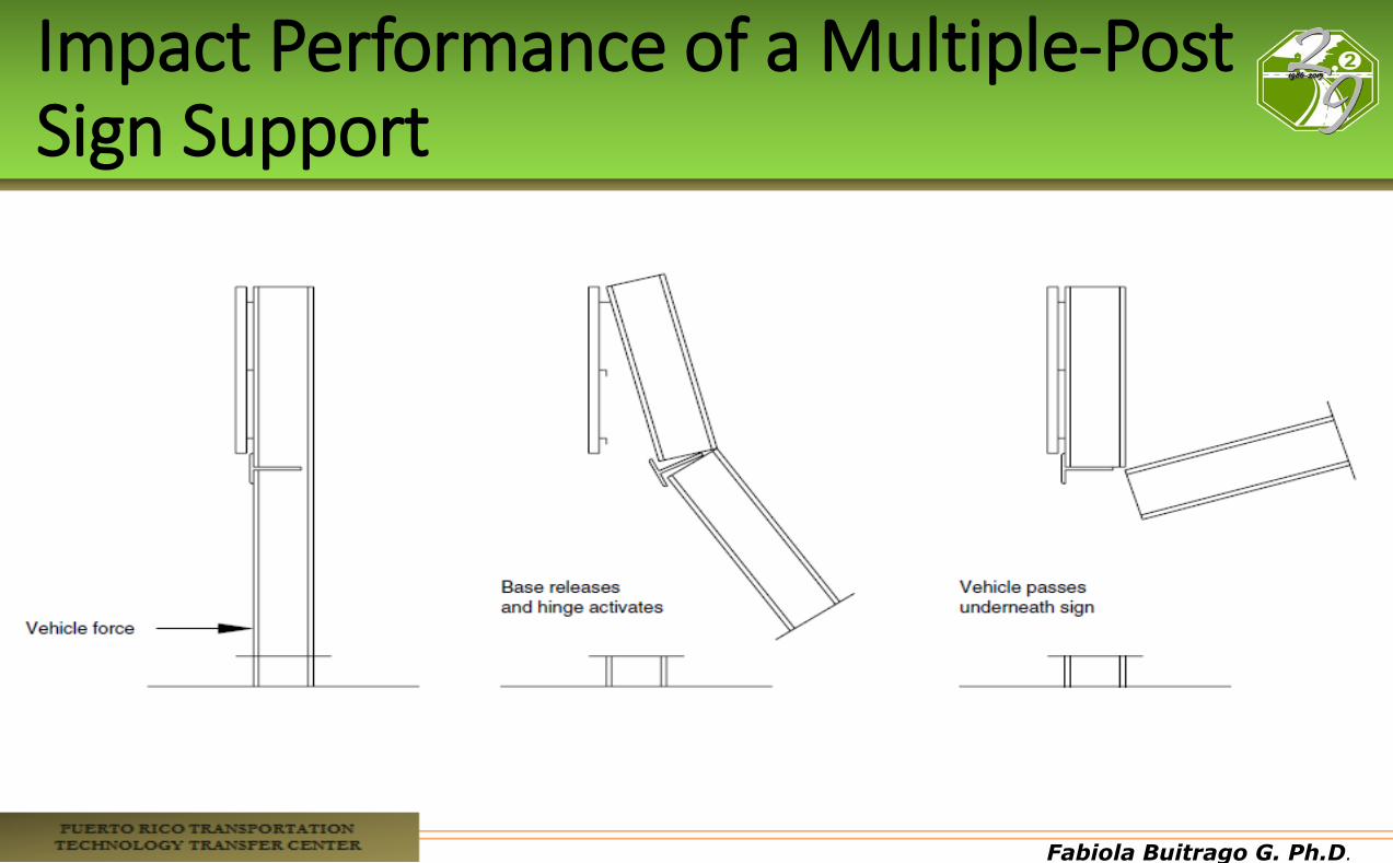
Impact Performance of a Multiple-Post Sign Support
Fabiola Buitrago G. Ph.D.
Large Roadside Signs Supports
Multidirectional Coupler Typical Unidirectional Slip Base
Perforated Fuse Plate Design Slotted Fuse Plate Design
Fabiola Buitrago G. Ph.D.
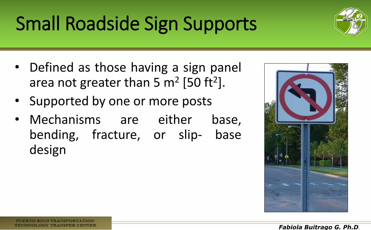
Small Roadside Sign Supports
• Defined as those having a sign panel area not greater than 5 m2 [50 ft2].
• Supported by one or more posts
• Mechanisms are either base, bending, fracture, or slip- base design
Fabiola Buitrago G. Ph.D.
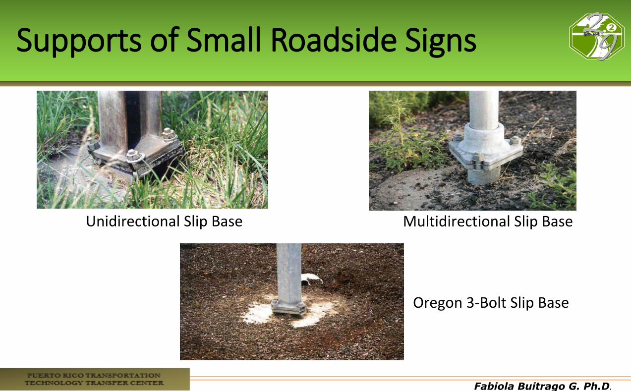
Supports of Small Roadside Signs
Unidirectional Slip Base Multidirectional Slip Base
Oregon 3-Bolt Slip Base
Fabiola Buitrago G. Ph.D.
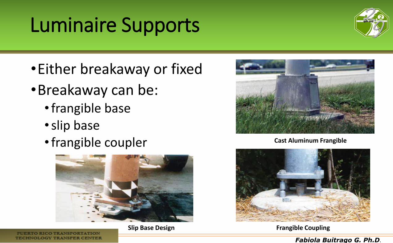
Luminaire Supports
•Either breakaway or fixed
•Breakaway can be: • frangible base • slip base • frangible coupler Cast Aluminum Frangible
Slip Base Design Frangible Coupling
Fabiola Buitrago G. Ph.D.
Considerations
• When impacted, should fall near the path of the vehicle
• The mast should rotate so it points away from the roadway when resting on the ground
• Heights should not exceed 18.5 m (60 ft)
Fabiola Buitrago G. Ph.D.
Traffic Signal Supports
• Include structures for post mounted traffic signals, structures with cantilevered arms, overhead mounted traffic signals, and span wire mounted traffic signals.
• The support post should be placed as far away from the roadway as practicable

Fabiola Buitrago G. Ph.D.
Fire Hydrants
• Whenever possible, should be located sufficiently far away from the roadway.
• They do not become obstructions for the motorist, yet are still readily accessible to and usable by emergency personnel.
• Any portion of the hydrant not designed to breakaway should be within 4 in. of the ground.
Fabiola Buitrago G. Ph.D.
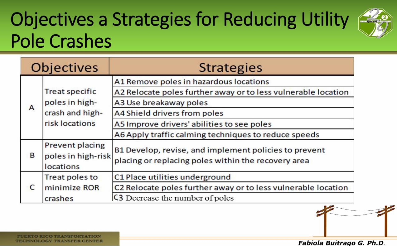
Objectives a Strategies for Reducing Utility Pole Crashes
Fabiola Buitrago G. Ph.D.
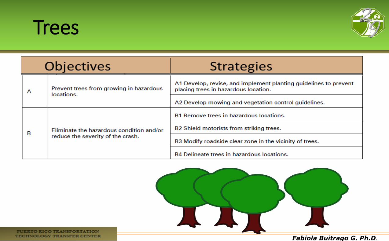
Trees

Fabiola Buitrago G. Ph.D.
Fabiola Buitrago G. Ph.D.
Fabiola Buitrago G. Ph.D.
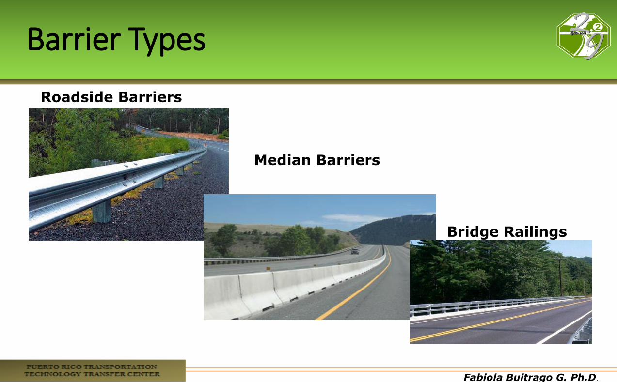
Barrier Types
Bridge Railings
Median Barriers
Roadside Barriers
Fabiola Buitrago G. Ph.D.
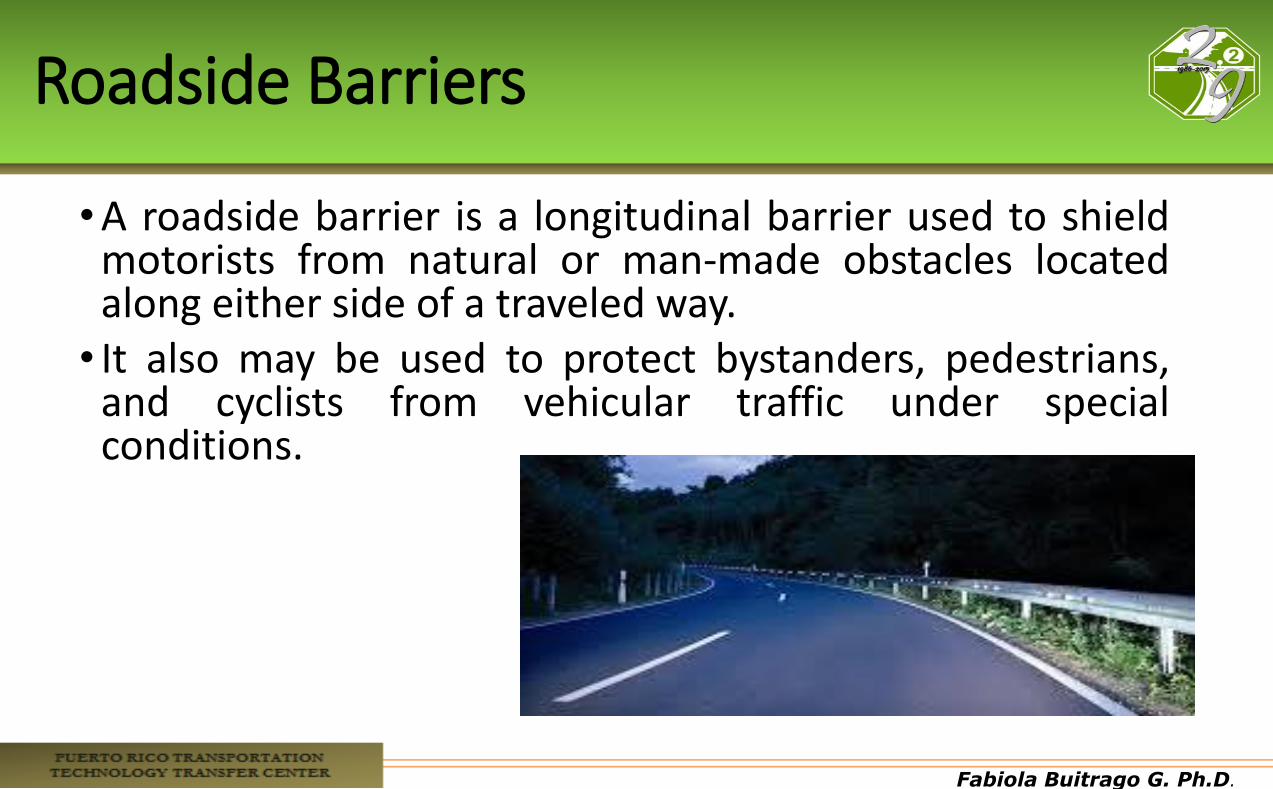
Roadside Barriers
•A roadside barrier is a longitudinal barrier used to shield motorists from natural or man-made obstacles located along either side of a traveled way. • It also may be used to protect bystanders, pedestrians,
and cyclists from vehicular traffic under special conditions.
Fabiola Buitrago G. Ph.D.
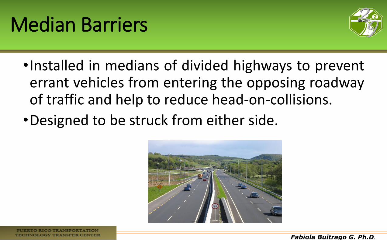
Median Barriers
•Installed in medians of divided highways to prevent errant vehicles from entering the opposing roadway of traffic and help to reduce head-on-collisions.
•Designed to be struck from either side.
Fabiola Buitrago G. Ph.D.
Bridge Railings
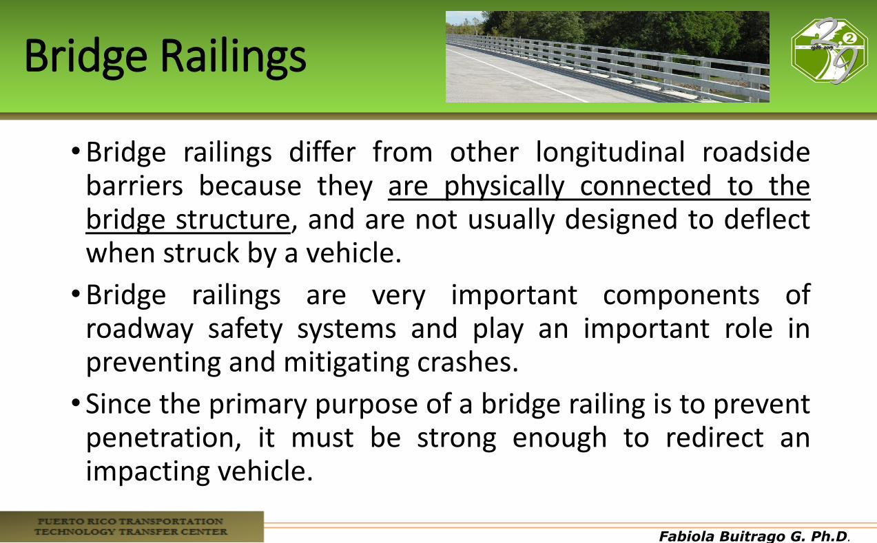
•Bridge railings differ from other longitudinal roadside barriers because they are physically connected to the bridge structure, and are not usually designed to deflect when struck by a vehicle.
•Bridge railings are very important components of roadway safety systems and play an important role in preventing and mitigating crashes.
•Since the primary purpose of a bridge railing is to prevent penetration, it must be strong enough to redirect an impacting vehicle.
Fabiola Buitrago G. Ph.D.
Purpose of Safety Barriers
•Provide a shield / prevent vehicle penetration to the hazard area •Redirect the vehicle after the impact occurs •Reduce the severity of the potential impact if not exist
barrier •Protect from:
• Deep embankment • A tree or pole • A bridge • A bridge column • Vehicles in the other direction
Fabiola Buitrago G. Ph.D.
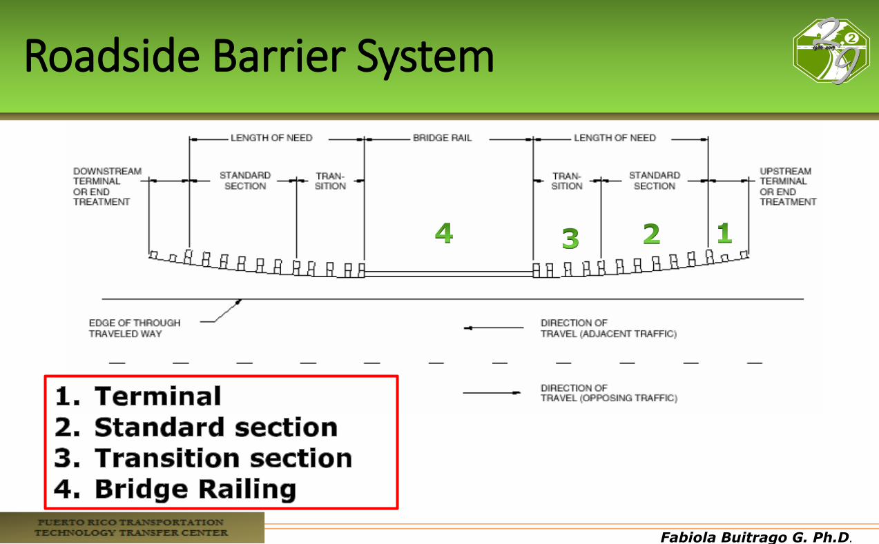
Roadside Barrier System
Fabiola Buitrago G. Ph.D.
Standards for Testing Crashes with Barriers
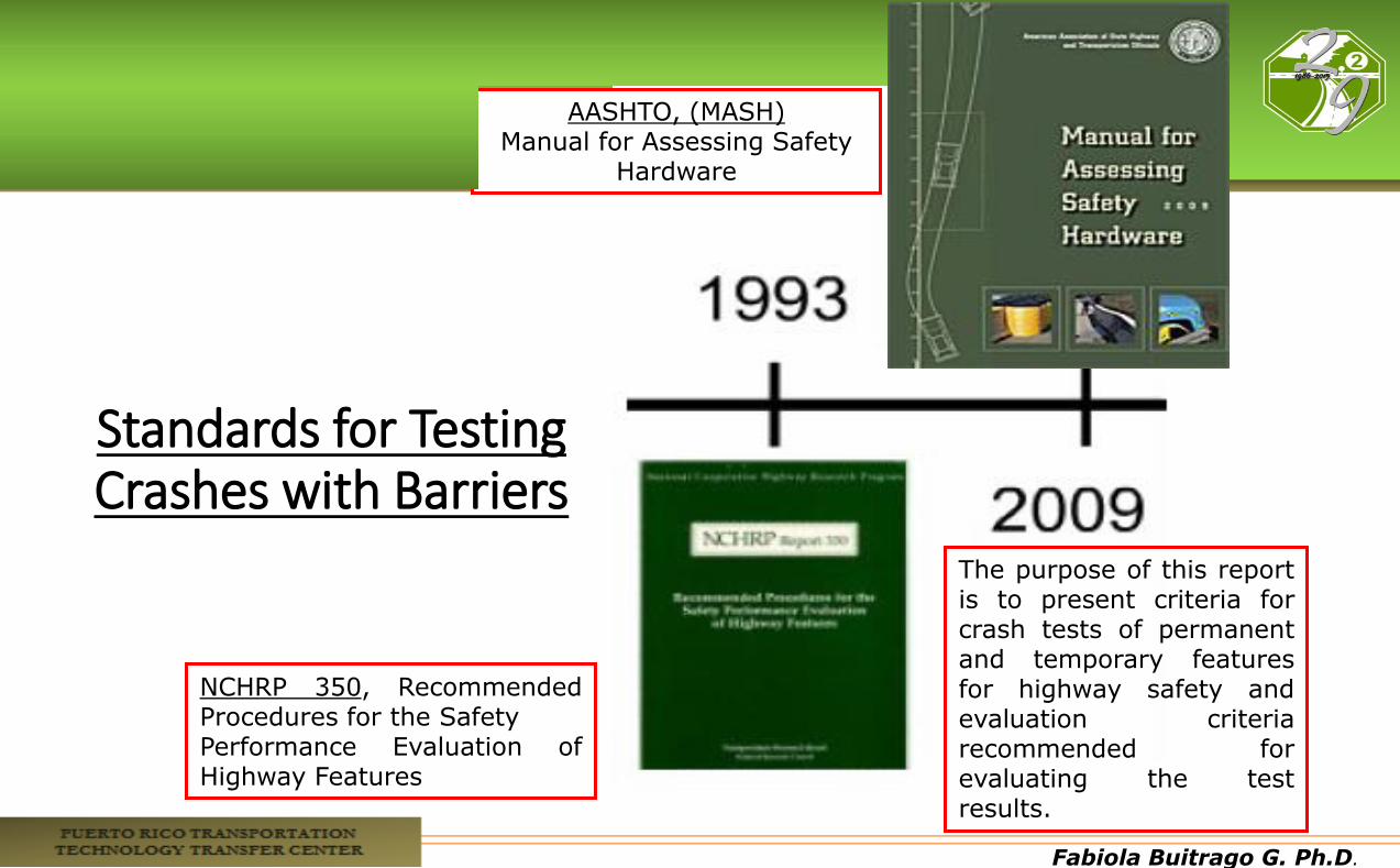
NCHRP 350, Recommended Procedures for the Safety Performance Evaluation of Highway Features
AASHTO, (MASH) Manual for Assessing Safety
Hardware
The purpose of this report is to present criteria for crash tests of permanent and temporary features for highway safety and evaluation criteria recommended for evaluating the test results.
Fabiola Buitrago G. Ph.D.
NCHRP 350 Crash Tests
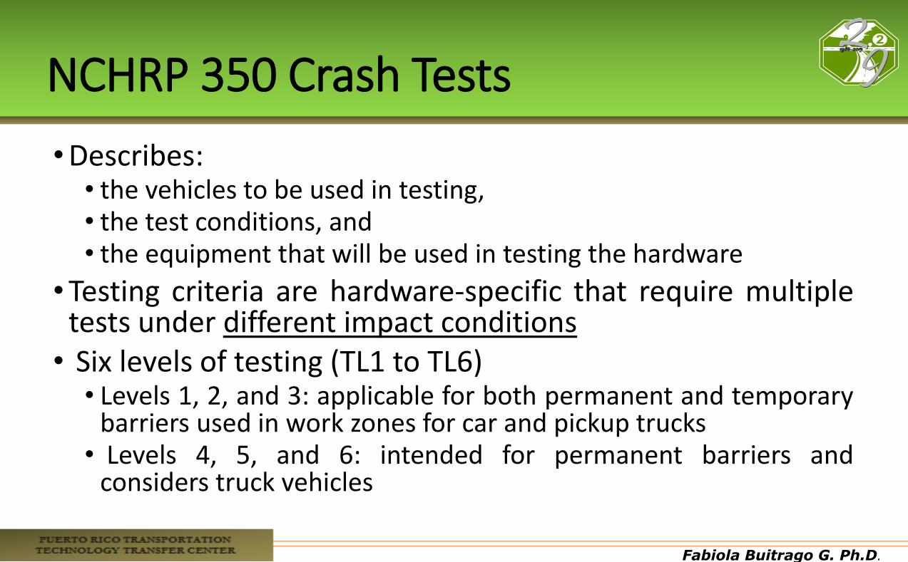
•Describes: • the vehicles to be used in testing, • the test conditions, and • the equipment that will be used in testing the hardware
•Testing criteria are hardware-specific that require multiple tests under different impact conditions • Six levels of testing (TL1 to TL6)
• Levels 1, 2, and 3: applicable for both permanent and temporary barriers used in work zones for car and pickup trucks
• Levels 4, 5, and 6: intended for permanent barriers and considers truck vehicles
Fabiola Buitrago G. Ph.D.
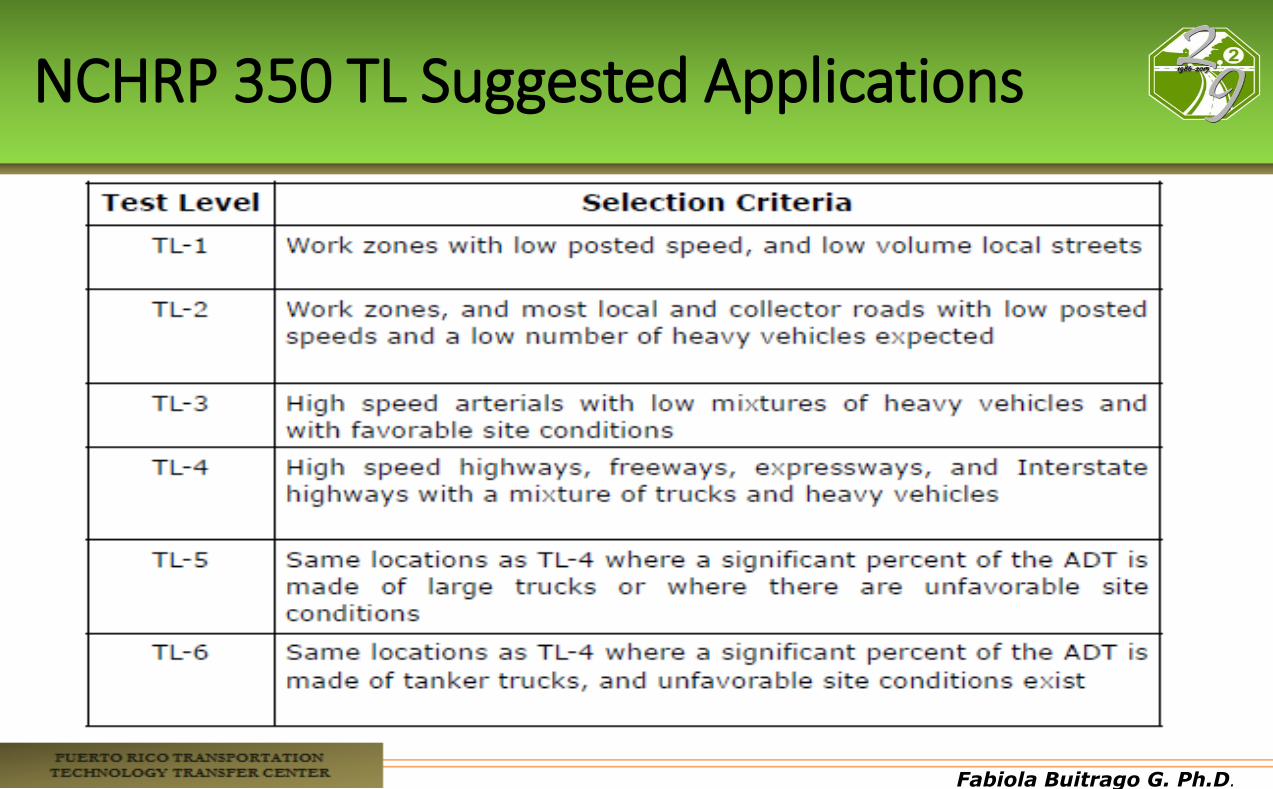
NCHRP 350 TL Suggested Applications
Fabiola Buitrago G. Ph.D.
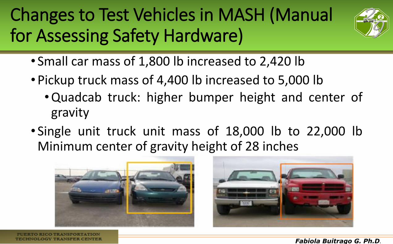
Changes to Test Vehicles in MASH (Manual for Assessing Safety Hardware)
•Small car mass of 1,800 lb increased to 2,420 lb
•Pickup truck mass of 4,400 lb increased to 5,000 lb •Quadcab truck: higher bumper height and center of
gravity
•Single unit truck unit mass of 18,000 lb to 22,000 lb Minimum center of gravity height of 28 inches
Fabiola Buitrago G. Ph.D.
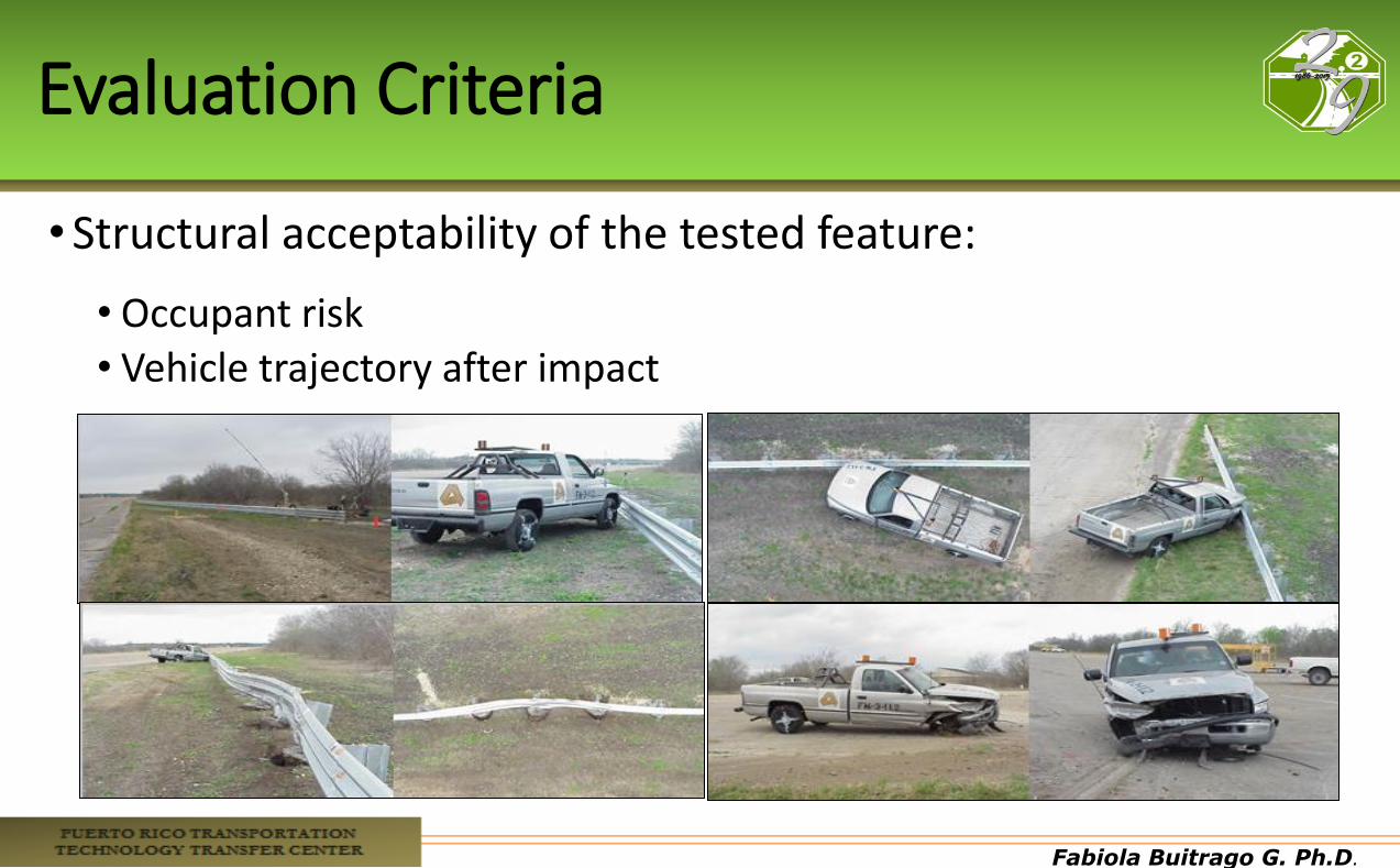
Evaluation Criteria
•Structural acceptability of the tested feature:
• Occupant risk • Vehicle trajectory after impact

Fabiola Buitrago G. Ph.D.
Structural Capability, MASH
•Depending on its proposed function, the feature: • Should contain and redirect the vehicle, or bring the vehicle to a
controlled stop
• Should not allow the vehicle to penetrate, underride, or override the installation ,
• Should operate in a expectable manner by breaking away, fracturing, or yielding
• Redirection, controlled penetration, or controlled stopping

Fabiola Buitrago G. Ph.D.
Post Impact Vehicle Trajectory
•Should not intrude into adjacent traffic Lanes
•Vehicle should remain upright during and after collision (not essential for TL3-6 trucks)
•Exit angle should be less than 60% of the impact angle
Fabiola Buitrago G. Ph.D.
Evaluation Criteria
• Crashworthiness is currently accepted if either of the following conditions are met: • A barrier system has met all of the evaluation criteria
listed in MASH or NCHRP Report 350 for each of the required crash tests, or
• A barrier system has been evaluated and found acceptable as a result of an operating performance evaluation
Fabiola Buitrago G. Ph.D.
Fabiola Buitrago G. Ph.D.
Fabiola Buitrago G. Ph.D.
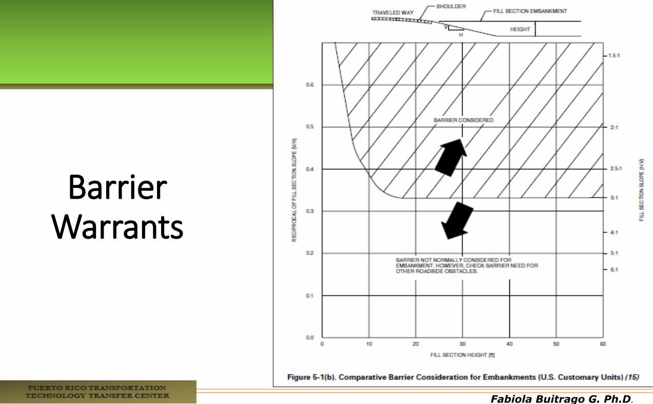
Barrier Warrants
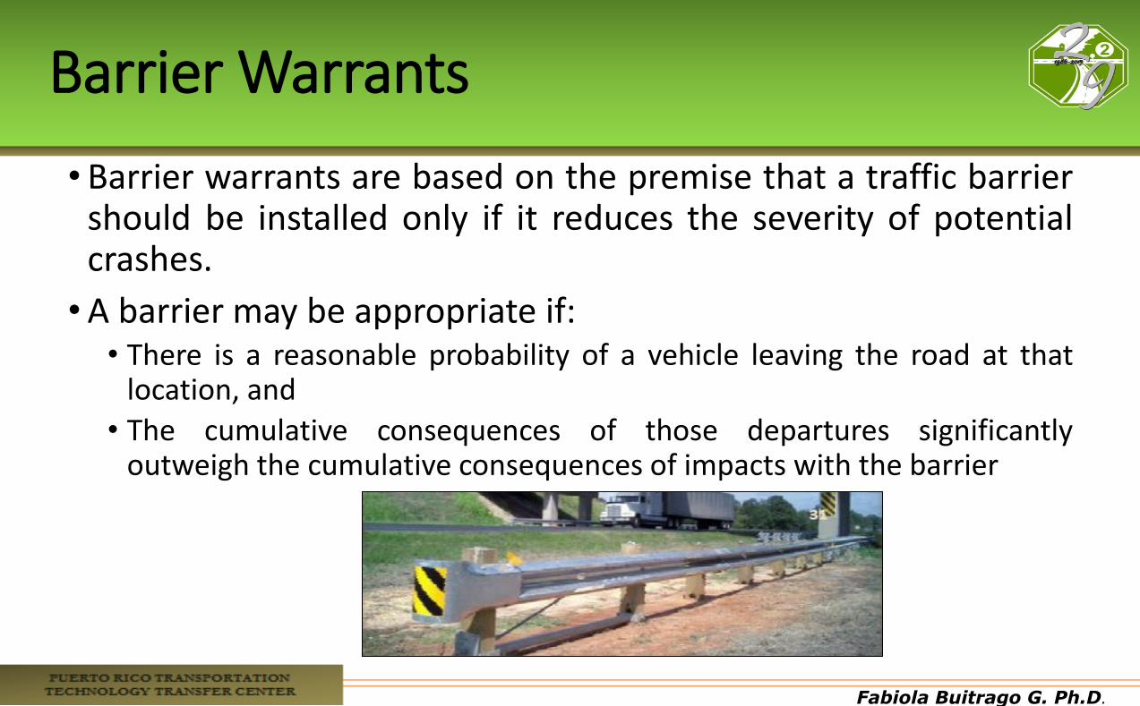
• Barrier warrants are based on the premise that a traffic barrier should be installed only if it reduces the severity of potential crashes.
•A barrier may be appropriate if: • There is a reasonable probability of a vehicle leaving the road at that
location, and
• The cumulative consequences of those departures significantly outweigh the cumulative consequences of impacts with the barrier
Fabiola Buitrago G. Ph.D.
Barrier Warrants
Fabiola Buitrago G. Ph.D.
Fabiola Buitrago G. Ph.D.
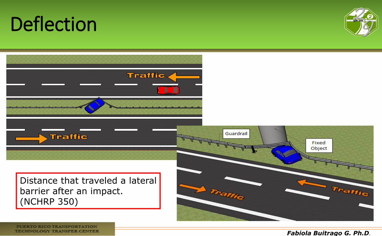
Deflection
Distance that traveled a lateral barrier after an impact. (NCHRP 350)
Fabiola Buitrago G. Ph.D.
Barrier Stiffness
Barriers are divided into three groups, based on the amount they deflect when struck by a vehicle and the mechanism the barrier uses to resist the impact forces:
• Flexible barriers • Semi-Rigid Barriers • Rigid Barriers
Fabiola Buitrago G. Ph.D.
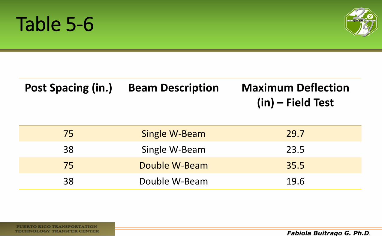
Table 5-6
Post Spacing (in.) Beam Description Maximum Deflection (in) – Field Test
75 Single W-Beam 29.7
38 Single W-Beam 23.5
75 Double W-Beam 35.5
38 Double W-Beam 19.6
Fabiola Buitrago G. Ph.D.
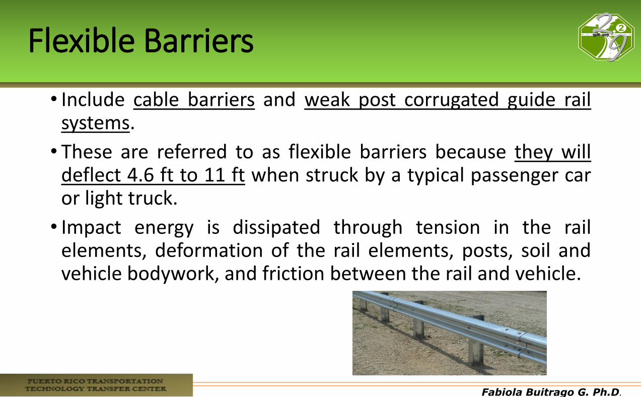
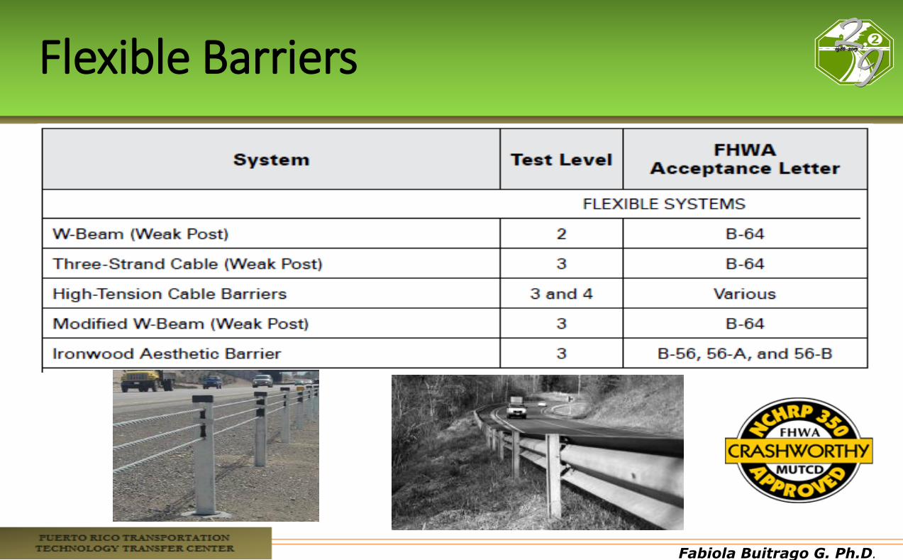
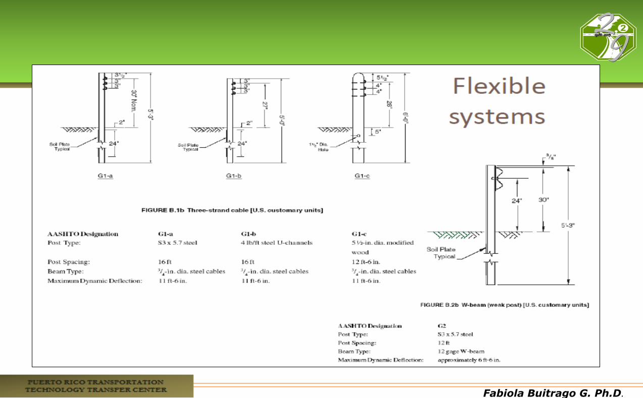
Flexible Barriers
• Include cable barriers and weak post corrugated guide rail systems.
• These are referred to as flexible barriers because they will deflect 4.6 ft to 11 ft when struck by a typical passenger car or light truck.
• Impact energy is dissipated through tension in the rail elements, deformation of the rail elements, posts, soil and vehicle bodywork, and friction between the rail and vehicle.
Fabiola Buitrago G. Ph.D.
Flexible Barriers
Fabiola Buitrago G. Ph.D.
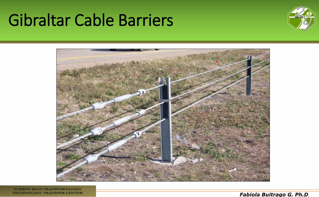
Gibraltar Cable Barriers
Fabiola Buitrago G. Ph.D.
Fabiola Buitrago G. Ph.D.
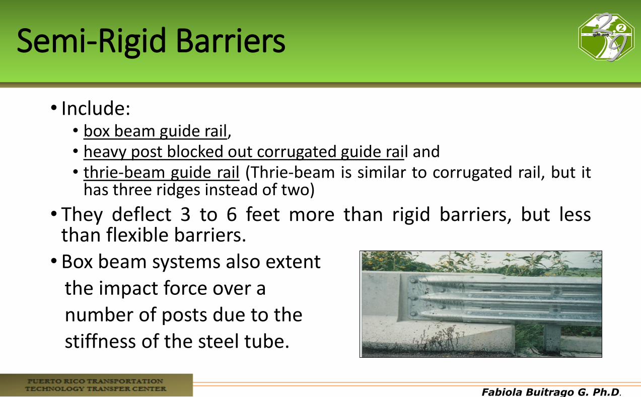
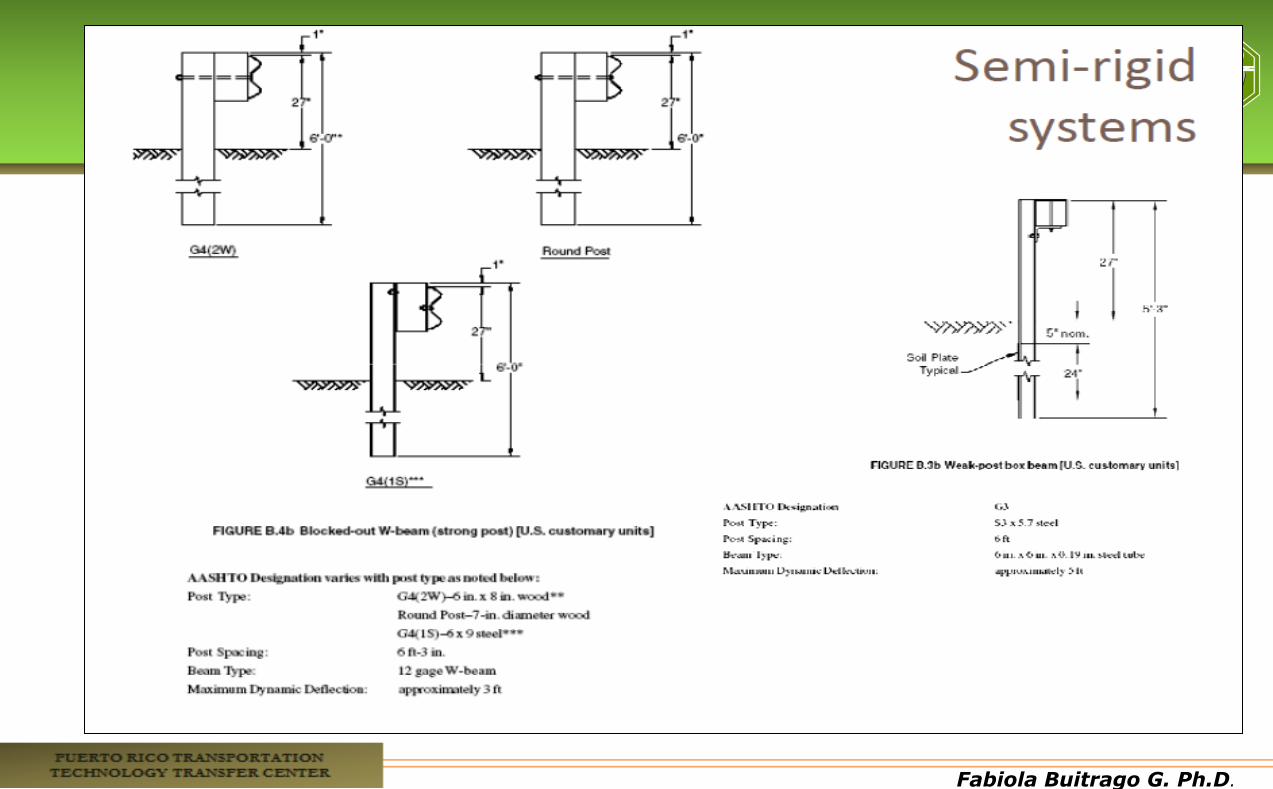
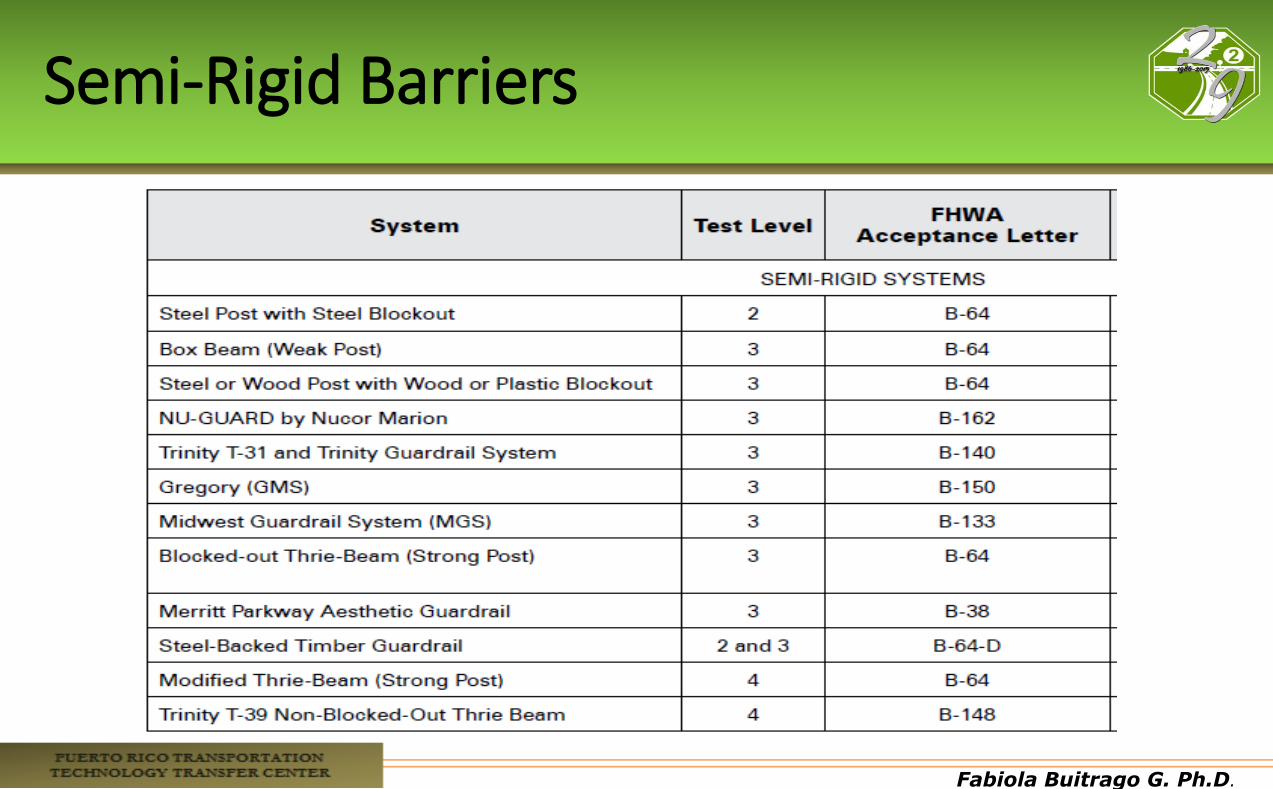
Semi-Rigid Barriers
• Include: • box beam guide rail, • heavy post blocked out corrugated guide rail and • thrie-beam guide rail (Thrie-beam is similar to corrugated rail, but it
has three ridges instead of two)
• They deflect 3 to 6 feet more than rigid barriers, but less than flexible barriers.
• Box beam systems also extent the impact force over a number of posts due to the stiffness of the steel tube.
Fabiola Buitrago G. Ph.D.
Fabiola Buitrago G. Ph.D.
Semi-Rigid Barriers
Fabiola Buitrago G. Ph.D.
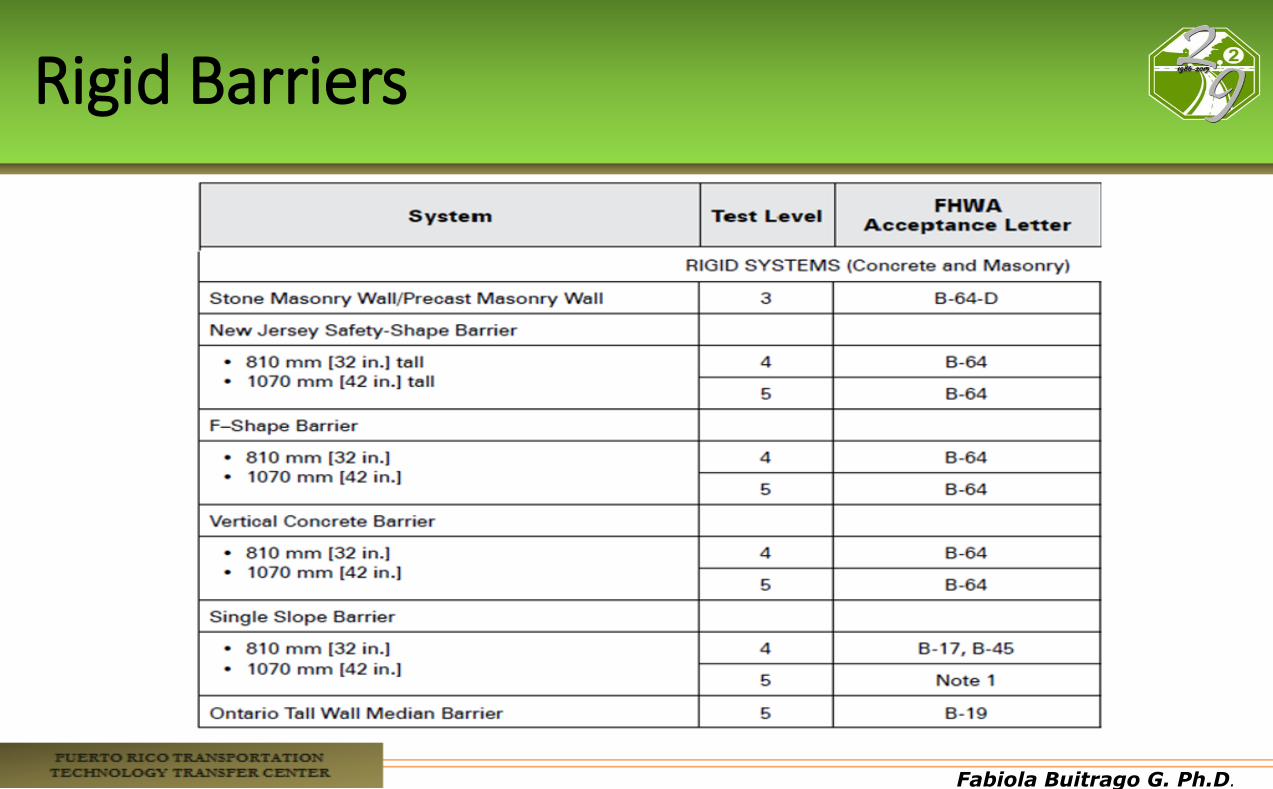
Rigid Barriers
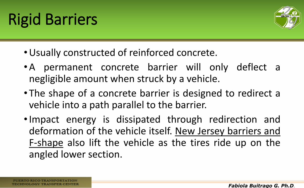
•Usually constructed of reinforced concrete.
•A permanent concrete barrier will only deflect a negligible amount when struck by a vehicle.
•The shape of a concrete barrier is designed to redirect a vehicle into a path parallel to the barrier.
• Impact energy is dissipated through redirection and deformation of the vehicle itself. New Jersey barriers and F-shape also lift the vehicle as the tires ride up on the angled lower section.
Fabiola Buitrago G. Ph.D.
Rigid Barriers

Fabiola Buitrago G. Ph.D.
Typical Section of Jersey Barrier
Fabiola Buitrago G. Ph.D.
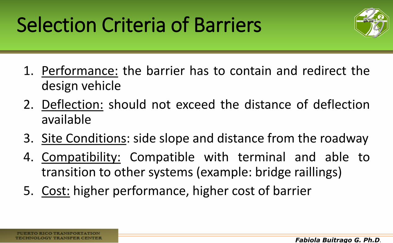
Selection Criteria of Barriers
1. Performance: the barrier has to contain and redirect the design vehicle
2. Deflection: should not exceed the distance of deflection available
3. Site Conditions: side slope and distance from the roadway
4. Compatibility: Compatible with terminal and able to transition to other systems (example: bridge raillings)
5. Cost: higher performance, higher cost of barrier
Fabiola Buitrago G. Ph.D.
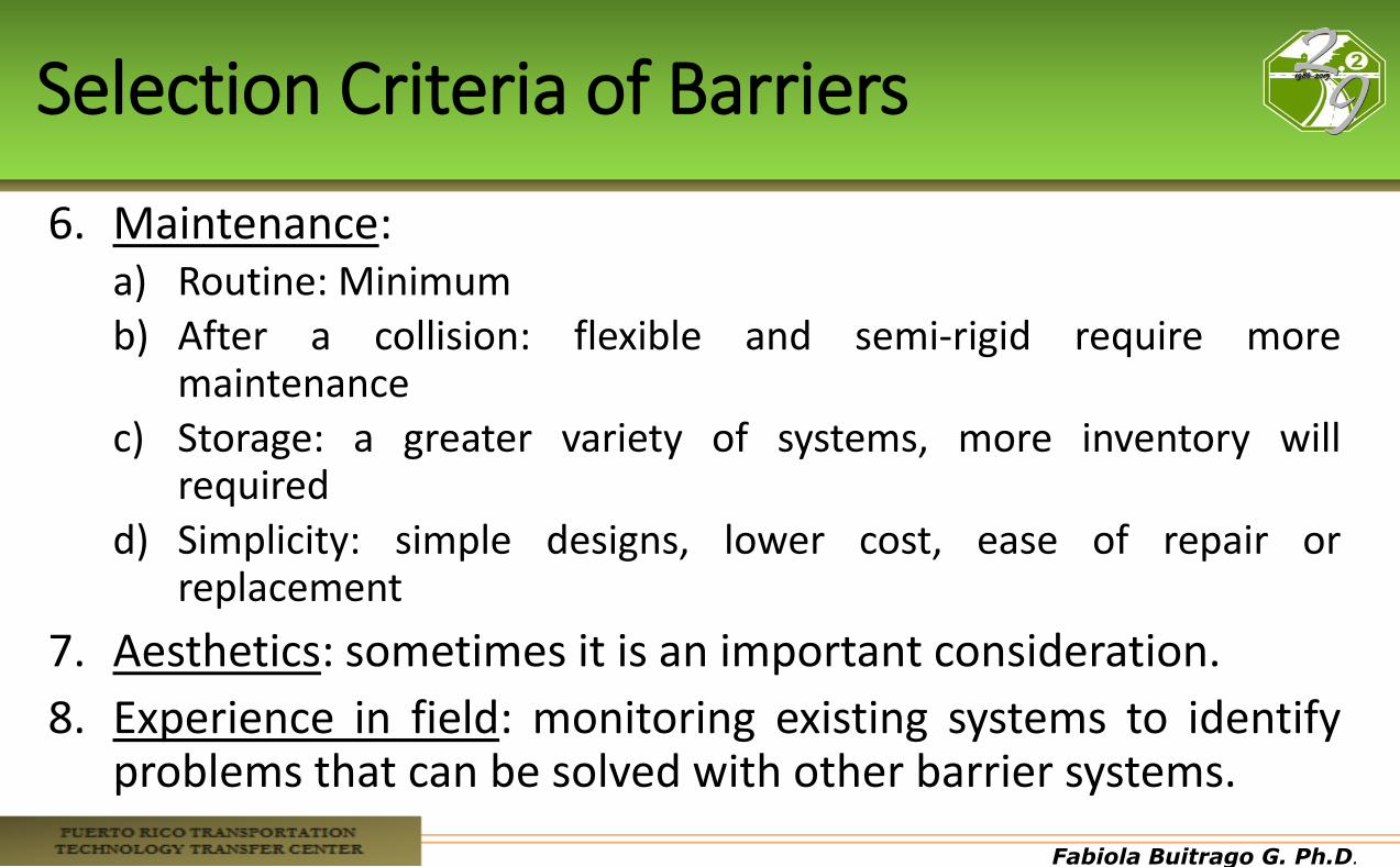
Selection Criteria of Barriers
6. Maintenance: a) Routine: Minimum b) After a collision: flexible and semi-rigid require more
maintenance c) Storage: a greater variety of systems, more inventory will
required d) Simplicity: simple designs, lower cost, ease of repair or
replacement
7. Aesthetics: sometimes it is an important consideration.
8. Experience in field: monitoring existing systems to identify problems that can be solved with other barrier systems.
Fabiola Buitrago G. Ph.D.
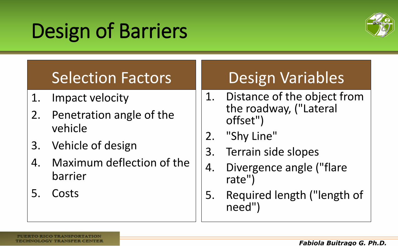
Design of Barriers
Selection Factors 1. Impact velocity
2. Penetration angle of the vehicle
3. Vehicle of design
4. Maximum deflection of the barrier
5. Costs
Design Variables 1. Distance of the object from
the roadway, ("Lateral offset")
2. "Shy Line"
3. Terrain side slopes
4. Divergence angle ("flare rate")
5. Required length ("length of need")
Fabiola Buitrago G. Ph.D.
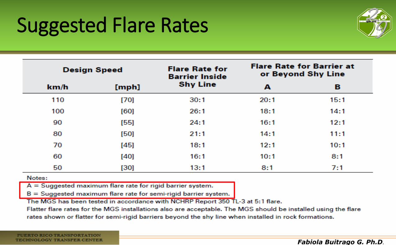
Flare Rate
• Barrier is considered flared when it is not parallel to the edge of the roadway
• Flare is normally used to locate the barrier terminal farther from the roadway • Pros
• Locate the barrier farther from the roadway • Minimize driver’s reaction to an obstacle • Reduce total length of rail needed
• Cons • The greater the flare rate, the higher the approach angle, the
higher the severity • Vehicle can be redirected back to roadway
Fabiola Buitrago G. Ph.D.
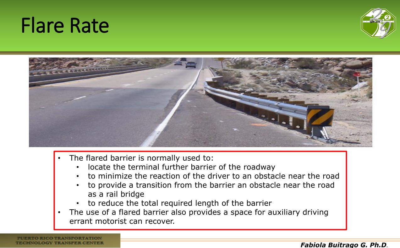
Flare Rate
• The flared barrier is normally used to: • locate the terminal further barrier of the roadway • to minimize the reaction of the driver to an obstacle near the road • to provide a transition from the barrier an obstacle near the road
as a rail bridge • to reduce the total required length of the barrier
• The use of a flared barrier also provides a space for auxiliary driving errant motorist can recover.
Fabiola Buitrago G. Ph.D.
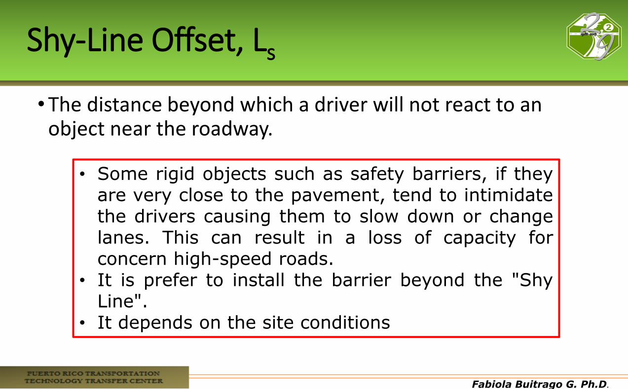
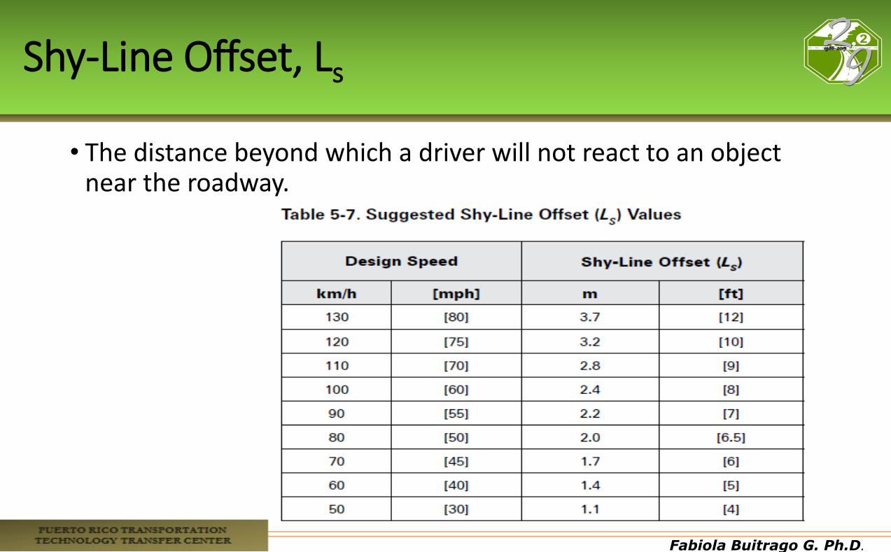
Shy-Line Offset, Ls
•The distance beyond which a driver will not react to an object near the roadway.
• Some rigid objects such as safety barriers, if they
are very close to the pavement, tend to intimidate the drivers causing them to slow down or change lanes. This can result in a loss of capacity for concern high-speed roads.
• It is prefer to install the barrier beyond the "Shy Line".
• It depends on the site conditions
Fabiola Buitrago G. Ph.D.
Suggested Flare Rates
Fabiola Buitrago G. Ph.D.
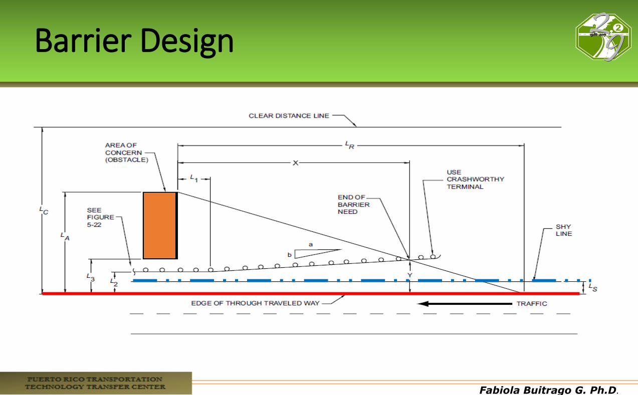
Barrier Design

Fabiola Buitrago G. Ph.D.
Primary Variables
• Lateral Extent of the Area of Concern LA: distance from the edge of the traveled way to the far side of the fixed object or to the outside edge of the clear zone of an embankment or a fixed object that extends beyond the clear zone.
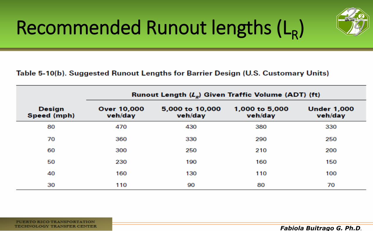
• Runout Length LR: distance from the object being shielded to the location where the vehicle departs from the traveled way (assumed).
• Tangent length from the Area of Concern L1: selected by the designer (zero if no flare)
Fabiola Buitrago G. Ph.D.
Recommended Runout lengths (LR)
Fabiola Buitrago G. Ph.D.
Shy-Line Offset, Ls
• The distance beyond which a driver will not react to an object near the roadway.
Fabiola Buitrago G. Ph.D.
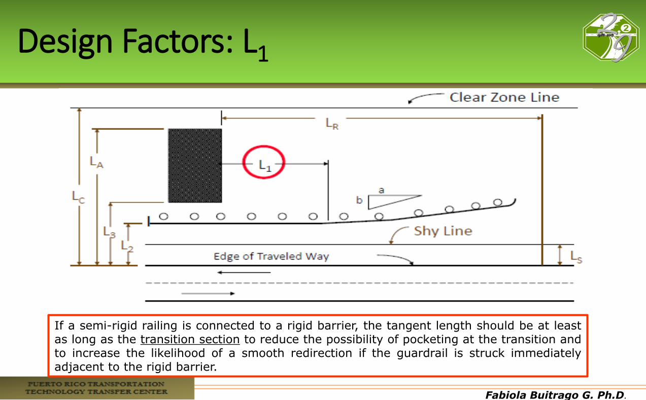
Design Factors: L1
If a semi-rigid railing is connected to a rigid barrier, the tangent length should be at least as long as the transition section to reduce the possibility of pocketing at the transition and to increase the likelihood of a smooth redirection if the guardrail is struck immediately adjacent to the rigid barrier.
Fabiola Buitrago G. Ph.D.
Transition Length
• It is necessary to provide continuity of protection when two different types of barriers are joined (semi-rigid and rigid example), the two must be tied, or when a roadside barrier is attached to a rigid object (i.e., concrete barrier or bridge railings).
•The transition length should be such that significant changes in the lateral strength not occur in a short distance.
•The transition length should be about 12 times the difference between the dynamic deflection barriers.

Fabiola Buitrago G. Ph.D.
Required Length of Need Before the Area of Concern
Fabiola Buitrago G. Ph.D.
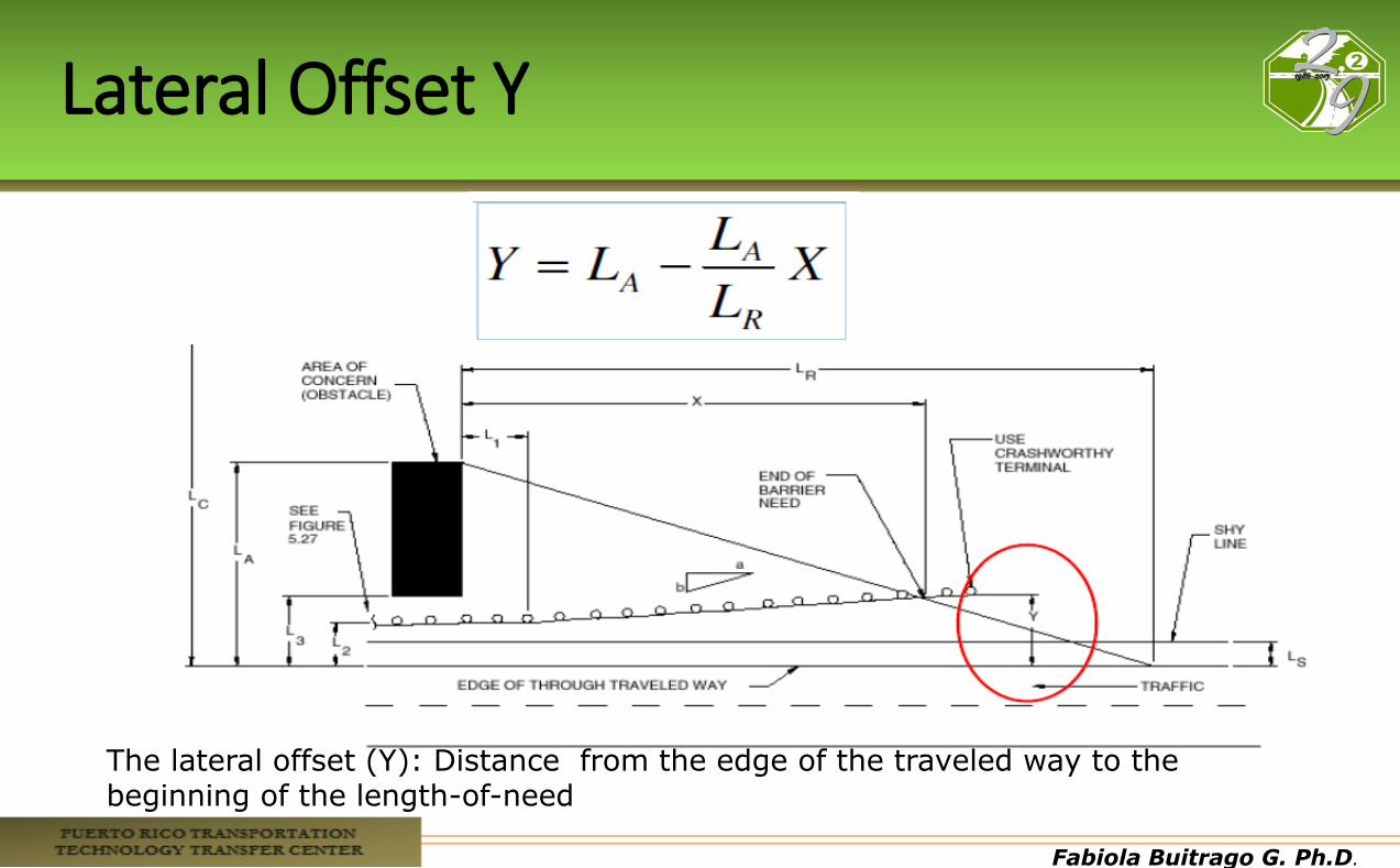
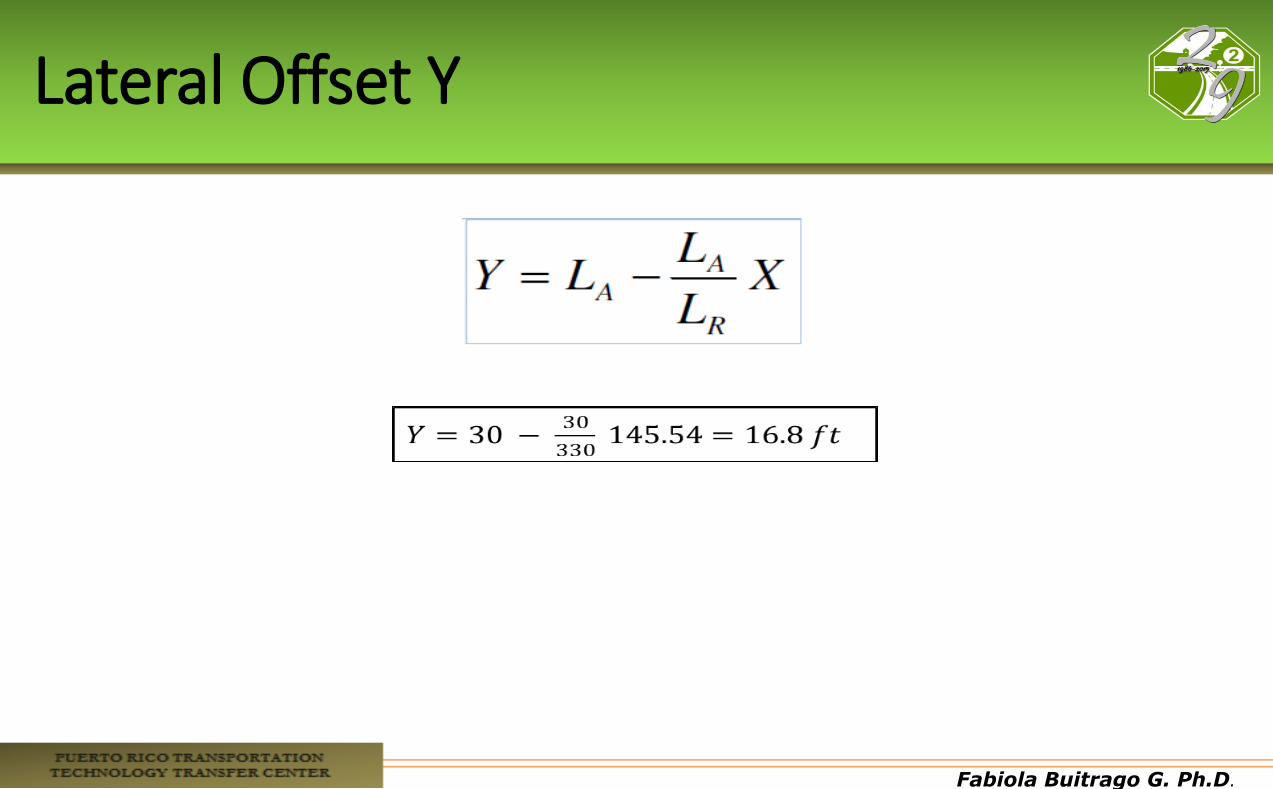
Lateral Offset Y
The lateral offset (Y): Distance from the edge of the traveled way to the beginning of the length-of-need
Fabiola Buitrago G. Ph.D.
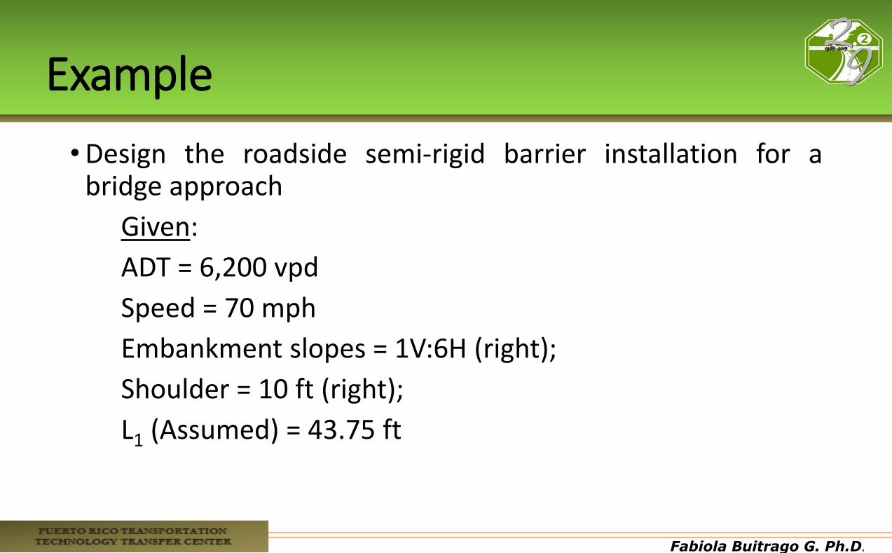
Example
•Design the roadside semi-rigid barrier installation for a bridge approach
Given:
ADT = 6,200 vpd
Speed = 70 mph
Embankment slopes = 1V:6H (right);
Shoulder = 10 ft (right);
L1 (Assumed) = 43.75 ft
Fabiola Buitrago G. Ph.D.
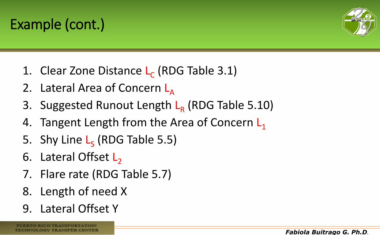
Example (cont.)
1. Clear Zone Distance LC (RDG Table 3.1)
2. Lateral Area of Concern LA
3. Suggested Runout Length LR (RDG Table 5.10)
4. Tangent Length from the Area of Concern L1
5. Shy Line LS (RDG Table 5.5)
6. Lateral Offset L2
7. Flare rate (RDG Table 5.7)
8. Length of need X
9. Lateral Offset Y
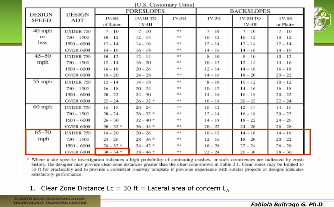
Fabiola Buitrago G. Ph.D.
1. Clear Zone Distance Lc = 30 ft = Lateral area of concern LA
Fabiola Buitrago G. Ph.D.
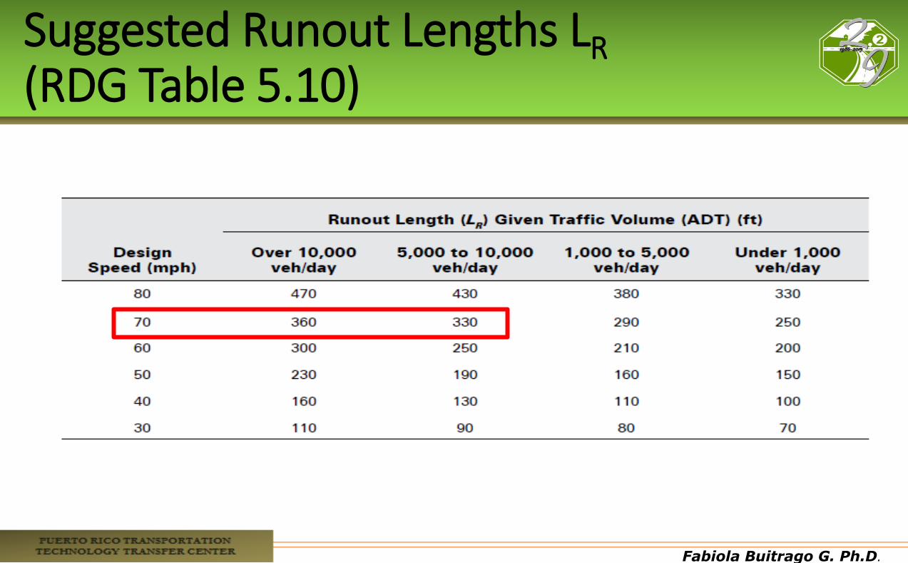
Suggested Runout Lengths LR (RDG Table 5.10)

Fabiola Buitrago G. Ph.D.
Shy Line Offset LS (Table 5.7)
Fabiola Buitrago G. Ph.D.
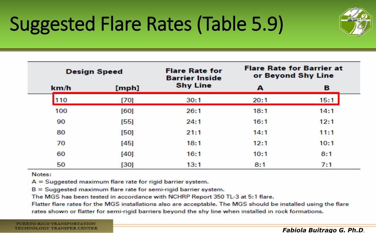
Suggested Flare Rates (Table 5.9)
Fabiola Buitrago G. Ph.D.
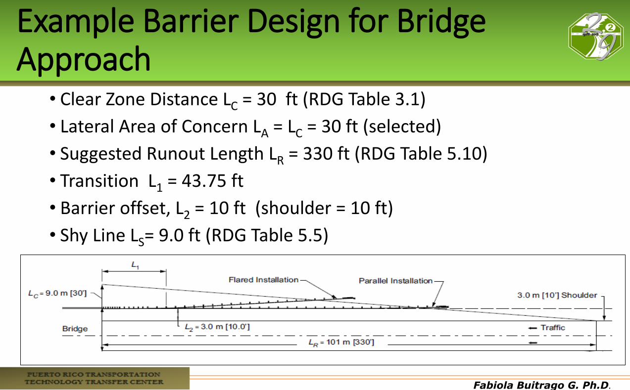
Example Barrier Design for Bridge Approach
• Clear Zone Distance LC = 30 ft (RDG Table 3.1)
• Lateral Area of Concern LA = LC = 30 ft (selected)
• Suggested Runout Length LR = 330 ft (RDG Table 5.10)
• Transition L1 = 43.75 ft
• Barrier offset, L2 = 10 ft (shoulder = 10 ft)
• Shy Line LS= 9.0 ft (RDG Table 5.5)
• Flare rate = 15:1 (Table 5-9)
Fabiola Buitrago G. Ph.D.
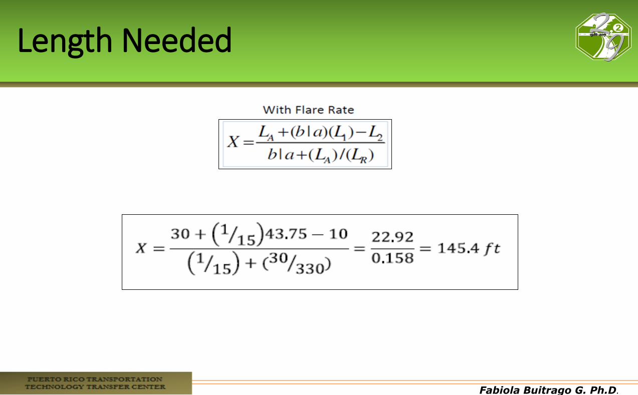
Length Needed
Fabiola Buitrago G. Ph.D.
Lateral Offset Y

Fabiola Buitrago G. Ph.D.
Discussion
• For the right-shoulder installation, the designer can measure 330 ft back from the bridge rail end and 30 ft laterally from the same point.
• The hypotenuse of this triangle approximates a vehicle’s runout path. To shield the bridge end and the river to the edge of the clear zone, the barrier installation should intersect this line. Based on the variables selected, a barrier length of 145.4 ft is needed.
• If a parallel installation was utilized, the length of need would be 220 ft.
Fabiola Buitrago G. Ph.D.
Fabiola Buitrago G. Ph.D.
Review
• A traffic barrier should be set as far as practical from the traveled way. This practice minimizes the likelihood that the barrier will be hit by providing a motorist with the maximum amount of traversable, unobstructed recovery area.
• It is critical that a vehicle makes contact with most types of barriers with its center-of-gravity at or near its normal position. This reduces the tendency for a vehicle to wedge under or go over the barrier.
• The slopes between a barrier installation and the roadway should be 1V:10H or flatter, or the barrier should be far enough from the road that a vehicle is on the ground with its suspension system neither compressed nor extended at the time of contact.
Fabiola Buitrago G. Ph.D.
Review

Fabiola Buitrago G. Ph.D.
Fabiola Buitrago G. Ph.D.
Fabiola Buitrago G. Ph.D.
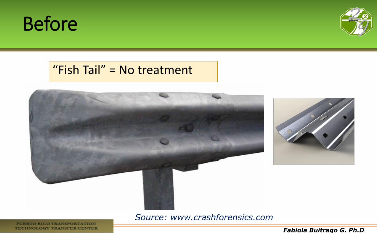
Before
“Fish Tail” = No treatment
Source: www.crashforensics.com
Fabiola Buitrago G. Ph.D.
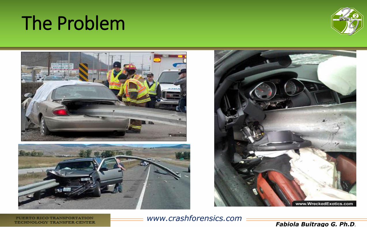
The Problem
www.crashforensics.com
Fabiola Buitrago G. Ph.D.
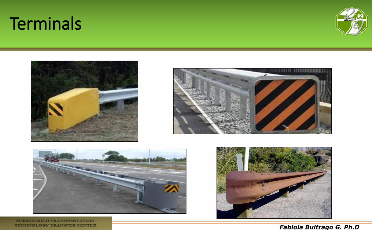
Terminals
Fabiola Buitrago G. Ph.D.
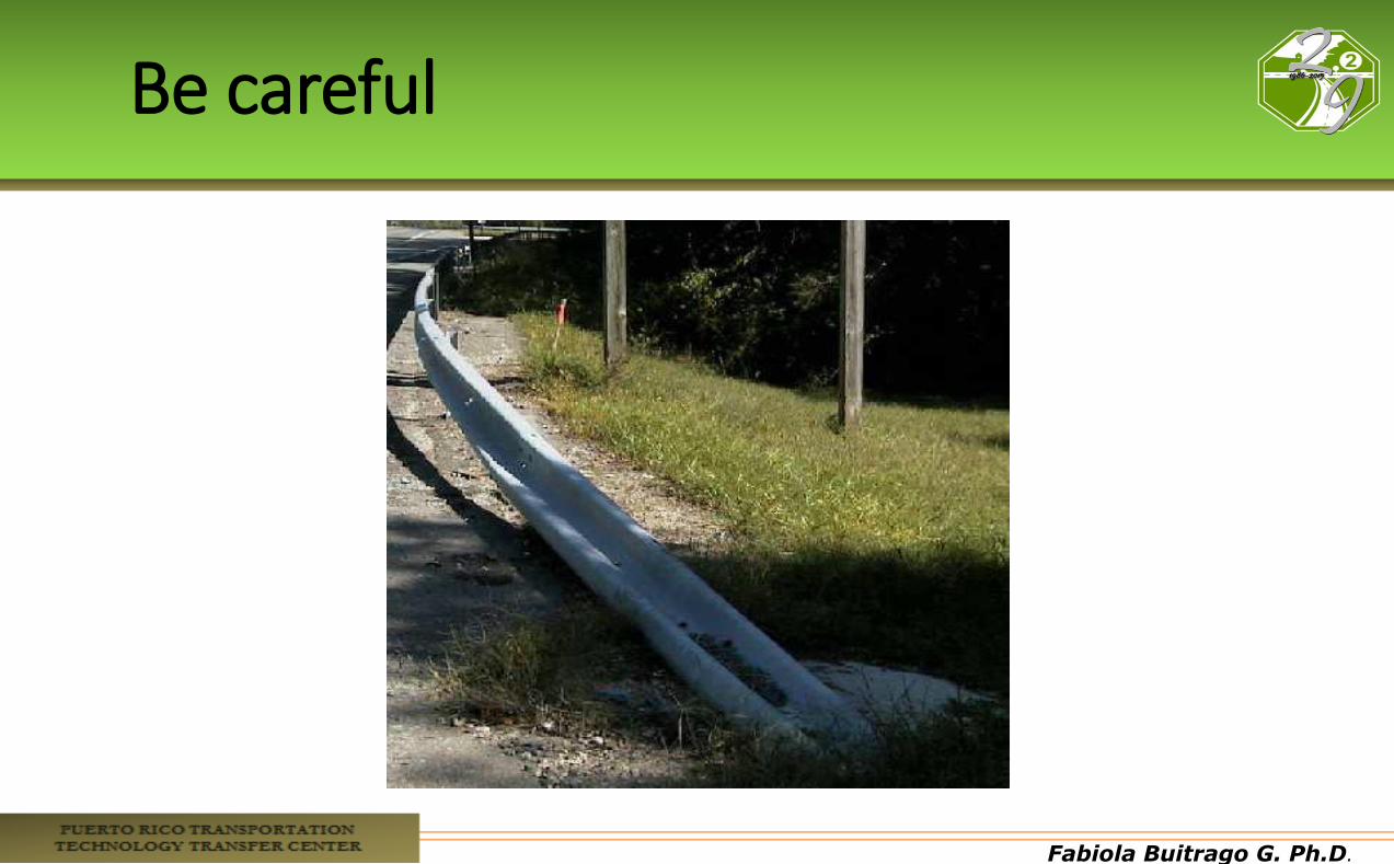
Be careful
Fabiola Buitrago G. Ph.D.
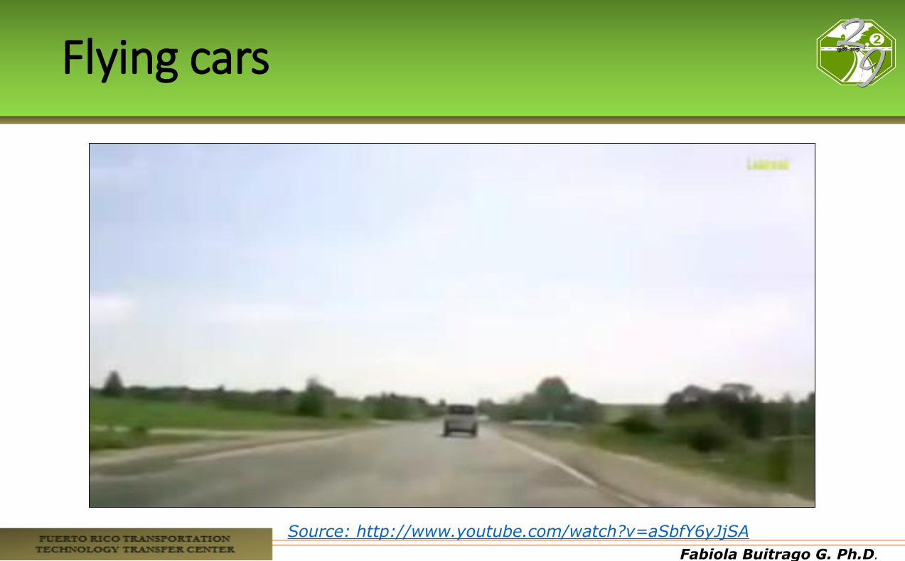
Flying cars
Source: http://www.youtube.com/watch?v=aSbfY6yJjSA
Fabiola Buitrago G. Ph.D.
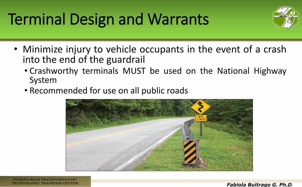
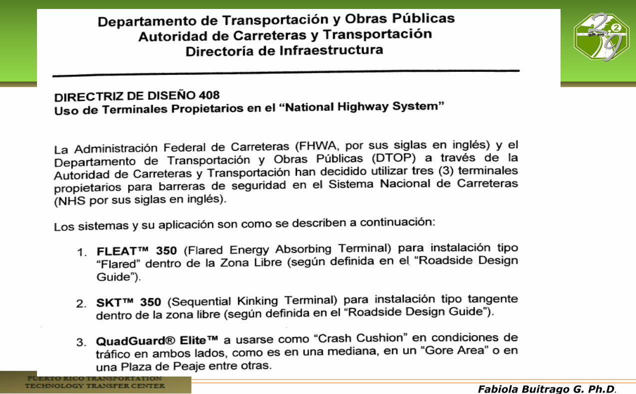
Terminal Design and Warrants
• Minimize injury to vehicle occupants in the event of a crash into the end of the guardrail • Crashworthy terminals MUST be used on the National Highway
System • Recommended for use on all public roads
Fabiola Buitrago G. Ph.D.
Evaluation Criteria
Crashworthiness is assumed if an end treatment has met all of the evaluation criteria set forth in either MASH or NCHRP Report 350 for each of the specified crash tests.
Fabiola Buitrago G. Ph.D.
Performance Requirements
• Gradually decelerates vehicle to a stop or redirects it when impacting end-on
• Safely redirecting vehicle that impacts side of device, at mid-length and near the nose
• Test levels w/ 1.8k car and 4.4k pick-up • TL-1: 30 mph • TL-2: 45 mph • TL-3: 60 mph
Fabiola Buitrago G. Ph.D.
Terminal Design Concepts
•Considerations in selecting an appropriate terminal for a given flexible or semi-rigid barrier installation: •Compatibility of the terminal with the barrier system; •Performance characteristics of the terminal
• energy-absorption potential, • configuration (tangent vs. flared), and • location of the length-of-need point
•Site-grading considerations.
Fabiola Buitrago G. Ph.D.
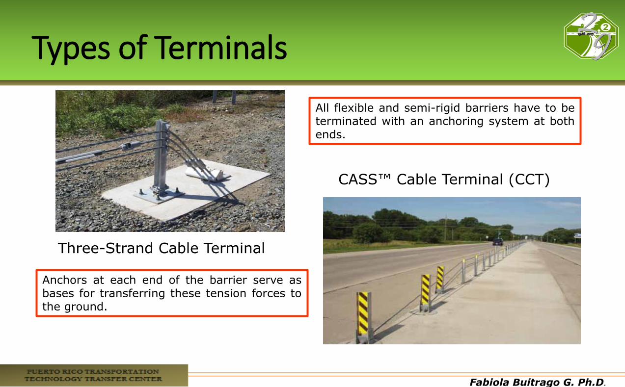
Types of Terminals
Three-Strand Cable Terminal
CASS™ Cable Terminal (CCT)
All flexible and semi-rigid barriers have to be terminated with an anchoring system at both ends.
Anchors at each end of the barrier serve as bases for transferring these tension forces to the ground.
Fabiola Buitrago G. Ph.D.
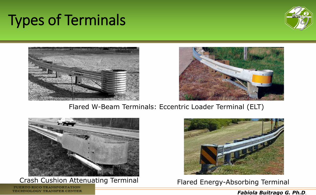
Types of Terminals
Flared W-Beam Terminals: Eccentric Loader Terminal (ELT)
Flared Energy-Absorbing Terminal Crash Cushion Attenuating Terminal
Fabiola Buitrago G. Ph.D.
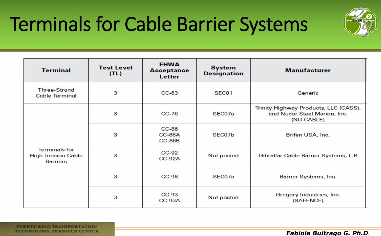
Terminals for Cable Barrier Systems
Fabiola Buitrago G. Ph.D.
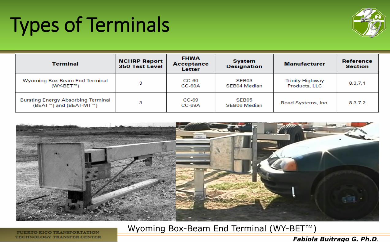
Types of Terminals
Wyoming Box-Beam End Terminal (WY-BET™)
Fabiola Buitrago G. Ph.D.
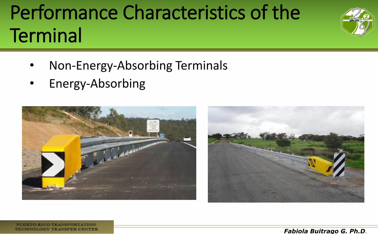
Performance Characteristics of the Terminal
• Non-Energy-Absorbing Terminals
• Energy-Absorbing
Fabiola Buitrago G. Ph.D.
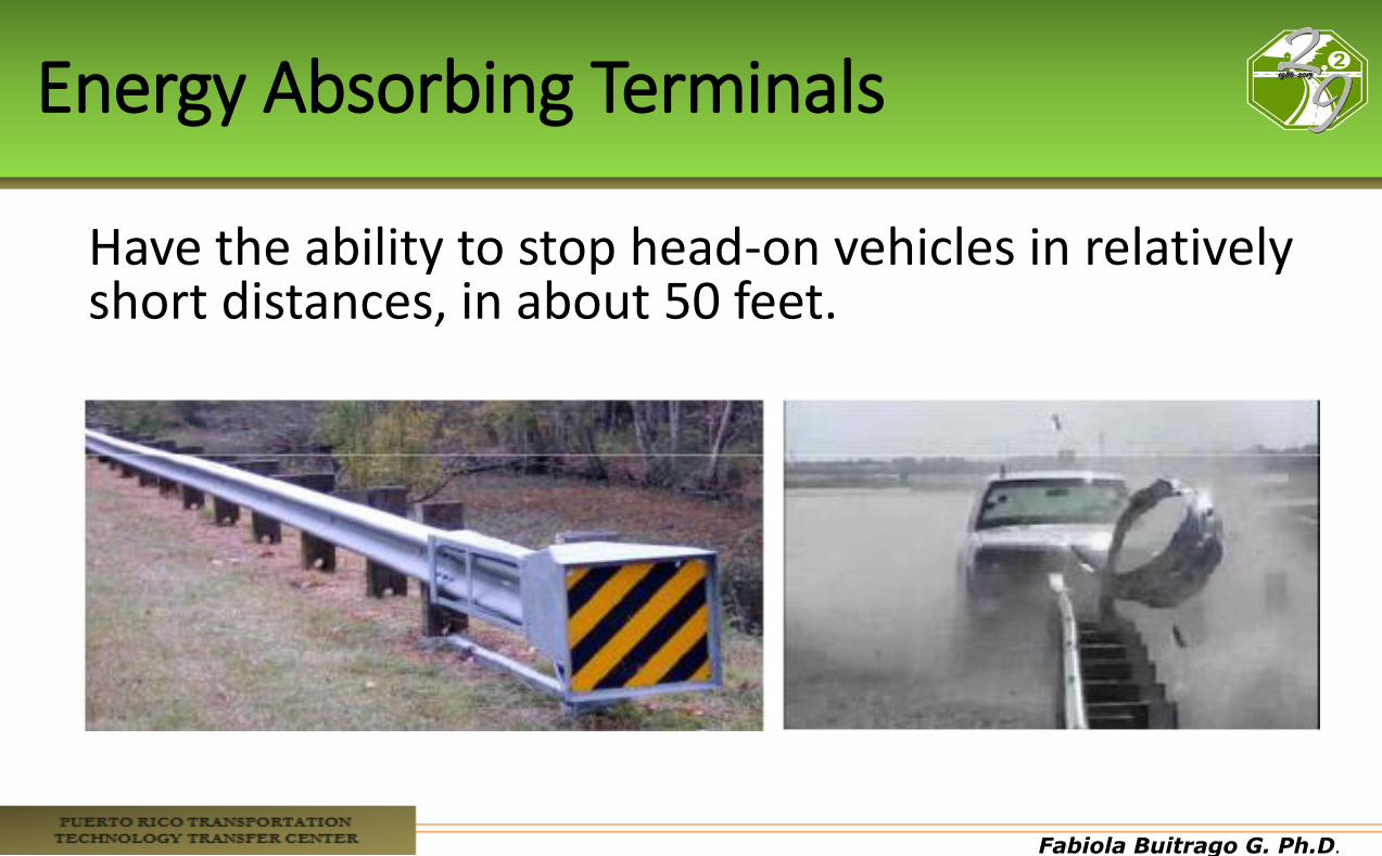
Energy Absorbing Terminals
Have the ability to stop head-on vehicles in relatively short distances, in about 50 feet.

Fabiola Buitrago G. Ph.D.
Non-Energy Absorbing Terminals
•Allow an un-braked vehicle to travel over 250 feet behind and parallel to the rail. •Vehicle speed is not significantly reduced.
Fabiola Buitrago G. Ph.D.
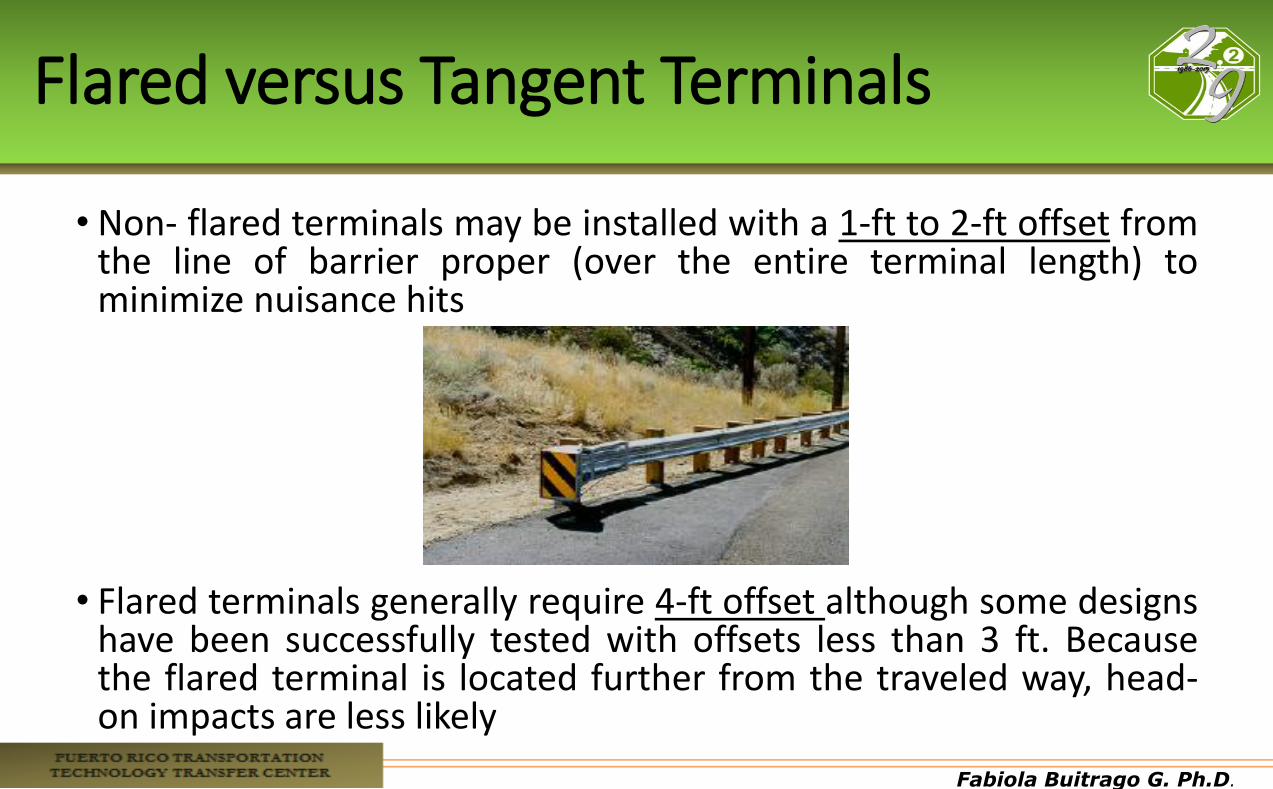
Flared versus Tangent Terminals
• Non- flared terminals may be installed with a 1-ft to 2-ft offset from the line of barrier proper (over the entire terminal length) to minimize nuisance hits
• Flared terminals generally require 4-ft offset although some designs have been successfully tested with offsets less than 3 ft. Because the flared terminal is located further from the traveled way, head-on impacts are less likely
Fabiola Buitrago G. Ph.D.
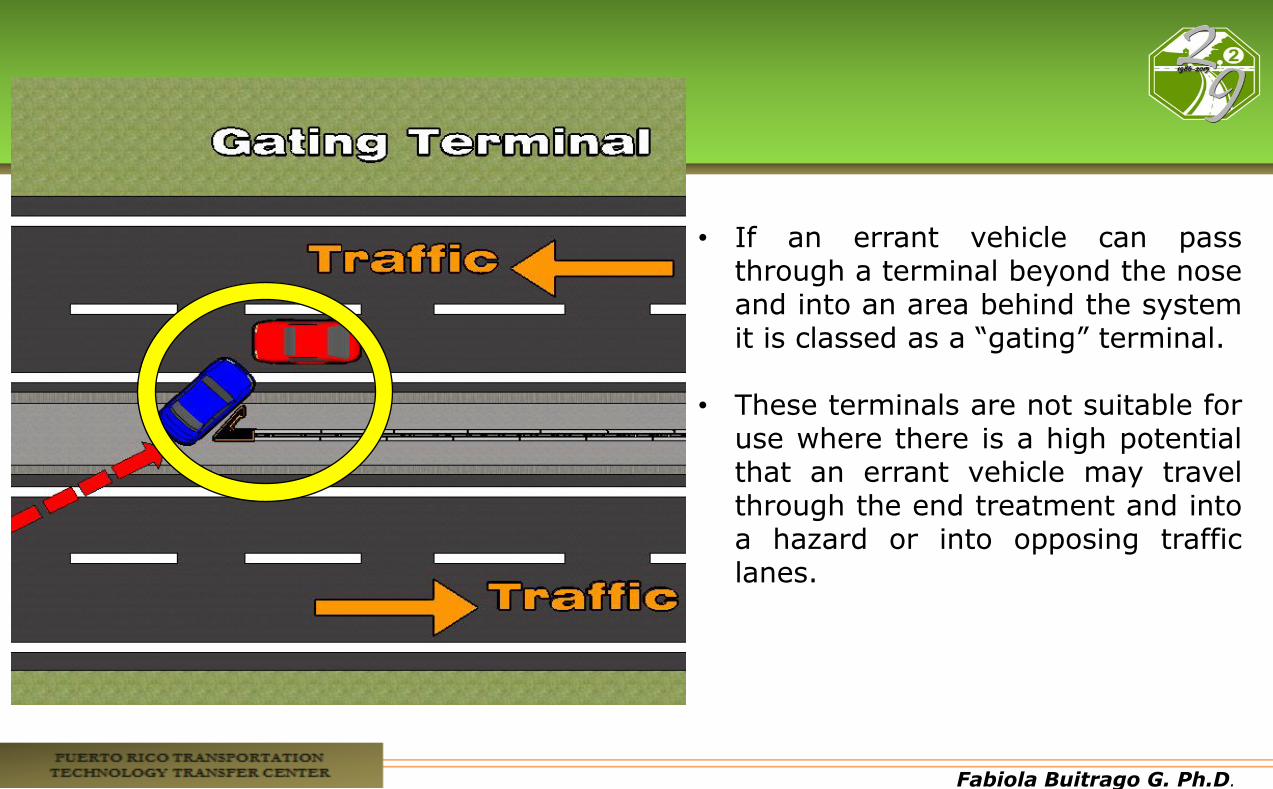
Gating Classification
•Gating: terminals that are designed to break away, pivot or hinge, and that allow a vehicle to pass through when impacted at an angle to the end, or at a point upstream of the beginning length - of-need of the safety barrier system.
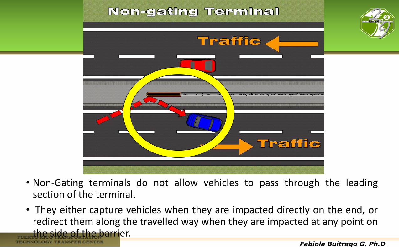
•Non-Gating: terminals that are designed to re-direct and absorb part of the energy of an impacting vehicle at any point along the terminal without allowing it to pass behind the safety barrier system.
Fabiola Buitrago G. Ph.D.
• If an errant vehicle can pass through a terminal beyond the nose and into an area behind the system it is classed as a “gating” terminal.
• These terminals are not suitable for
use where there is a high potential that an errant vehicle may travel through the end treatment and into a hazard or into opposing traffic lanes.
Fabiola Buitrago G. Ph.D.
• Non-Gating terminals do not allow vehicles to pass through the leading section of the terminal.
• They either capture vehicles when they are impacted directly on the end, or redirect them along the travelled way when they are impacted at any point on the side of the barrier.
Fabiola Buitrago G. Ph.D.
Anchorage Design Concepts
•All flexible and semi-rigid barriers need to be terminated with an anchor system at both ends.
•Anchorages at each end of the barrier serve as foundations to transfer these tension forces to the ground.
• If the barrier end treatment is not required to be crashworthy (e.g., a trailing end on a one-way roadway or an end located outside of the clear zone), a lower-cost anchorage system may be used.
Fabiola Buitrago G. Ph.D.
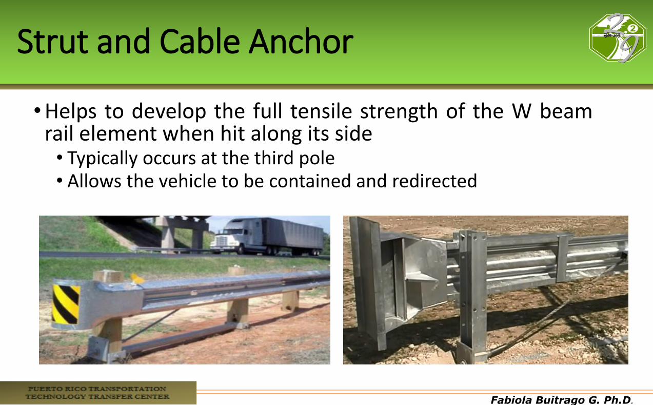
Strut and Cable Anchor
•Helps to develop the full tensile strength of the W beam rail element when hit along its side • Typically occurs at the third pole • Allows the vehicle to be contained and redirected
Fabiola Buitrago G. Ph.D.
Fabiola Buitrago G. Ph.D.
Fabiola Buitrago G. Ph.D.
Fabiola Buitrago G. Ph.D.
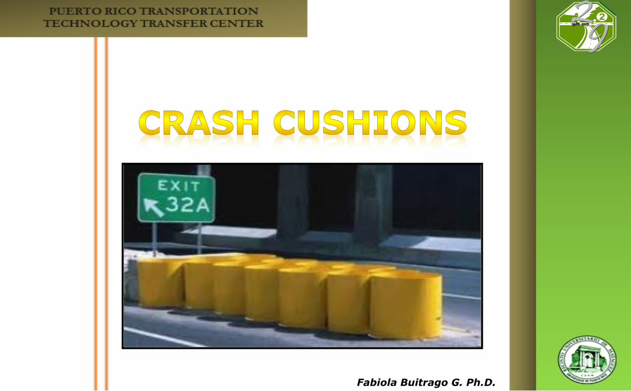
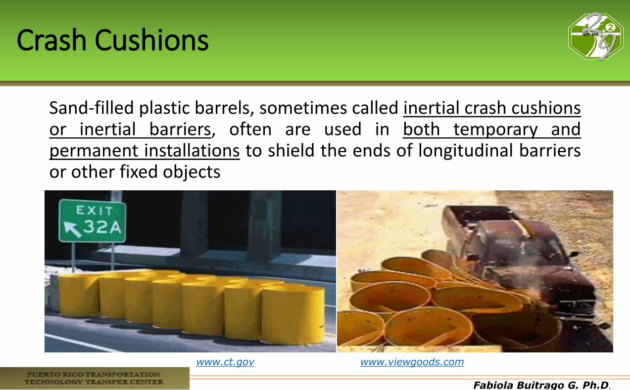
Crash Cushions
Sand-filled plastic barrels, sometimes called inertial crash cushions or inertial barriers, often are used in both temporary and permanent installations to shield the ends of longitudinal barriers or other fixed objects
www.ct.gov www.viewgoods.com
Fabiola Buitrago G. Ph.D.
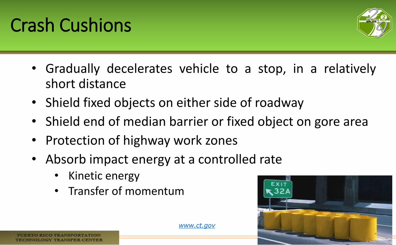
Crash Cushions
• Gradually decelerates vehicle to a stop, in a relatively short distance
• Shield fixed objects on either side of roadway
• Shield end of median barrier or fixed object on gore area
• Protection of highway work zones
• Absorb impact energy at a controlled rate • Kinetic energy • Transfer of momentum
www.ct.gov
Fabiola Buitrago G. Ph.D.
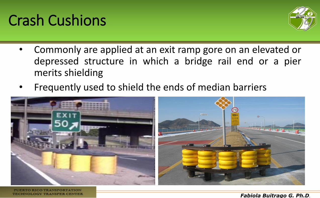
Crash Cushions
• Commonly are applied at an exit ramp gore on an elevated or depressed structure in which a bridge rail end or a pier merits shielding
• Frequently used to shield the ends of median barriers
Fabiola Buitrago G. Ph.D.
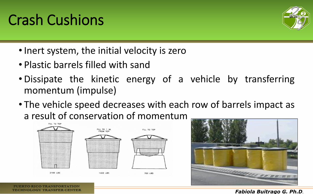
Crash Cushions
• Inert system, the initial velocity is zero
• Plastic barrels filled with sand
•Dissipate the kinetic energy of a vehicle by transferring momentum (impulse)
• The vehicle speed decreases with each row of barrels impact as a result of conservation of momentum
Fabiola Buitrago G. Ph.D.
Law of Conservation of Momentum
•Momentum: •Quantity expressing the motion of a body and its resistance
to reduce the velocity. • It is the product of its mass and its velocity.
•Conservation of Momentum: • For a collision between two objects in an isolated system,
the total momentum of the two objects before the collision equals the momentum after the collision.
• The momentum that lost the first object is the momentum that wins the second object.
Fabiola Buitrago G. Ph.D.
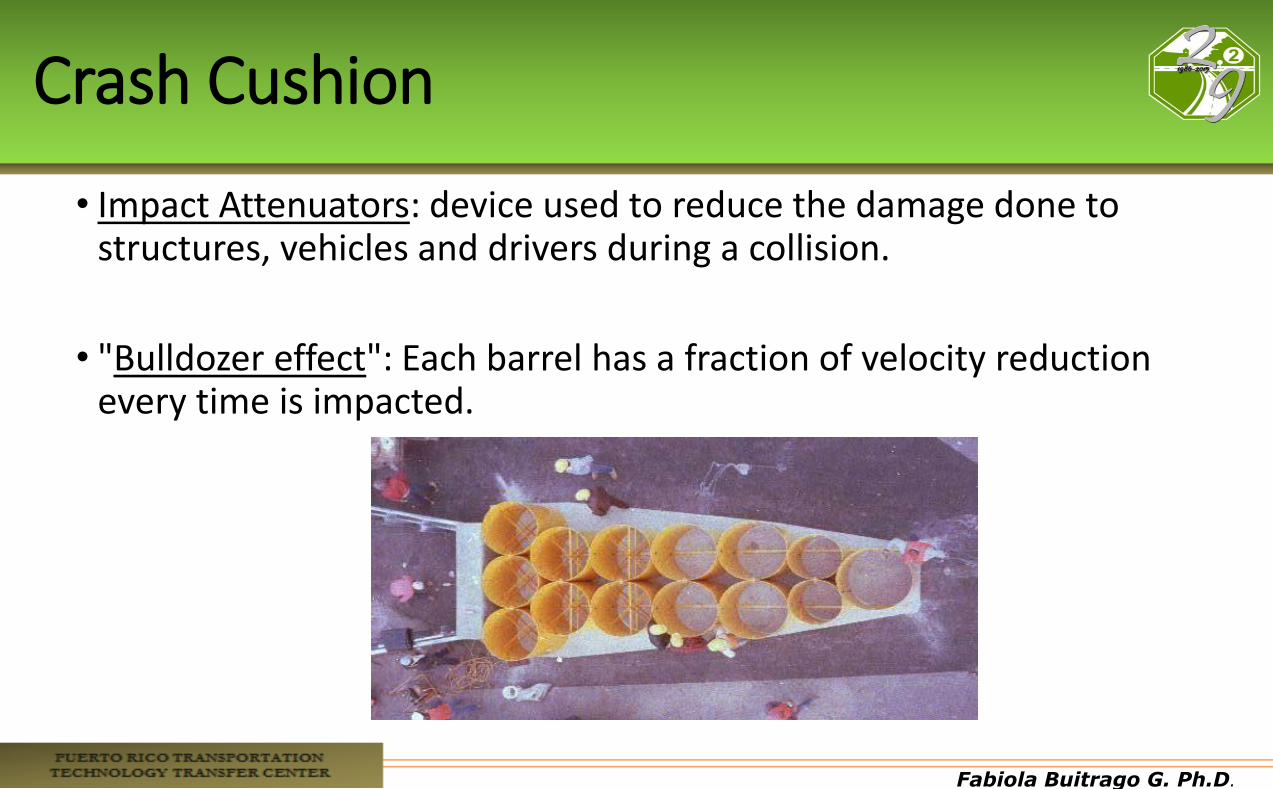
Crash Cushion
• Impact Attenuators: device used to reduce the damage done to structures, vehicles and drivers during a collision.
• "Bulldozer effect": Each barrel has a fraction of velocity reduction every time is impacted.
Fabiola Buitrago G. Ph.D.
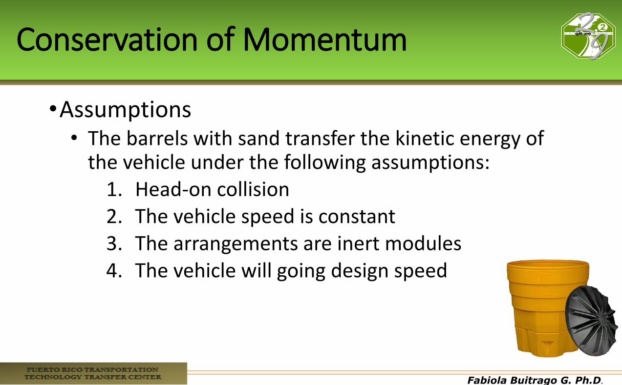
Conservation of Momentum
•Assumptions • The barrels with sand transfer the kinetic energy of
the vehicle under the following assumptions: 1. Head-on collision 2. The vehicle speed is constant 3. The arrangements are inert modules 4. The vehicle will going design speed
Fabiola Buitrago G. Ph.D.
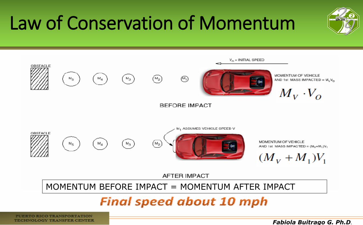
Law of Conservation of Momentum
MOMENTUM BEFORE IMPACT = MOMENTUM AFTER IMPACT
Fabiola Buitrago G. Ph.D.
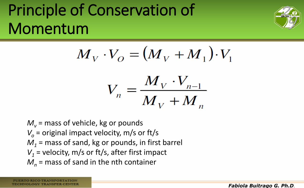
Principle of Conservation of Momentum
Mv = mass of vehicle, kg or pounds Vo = original impact velocity, m/s or ft/s M1 = mass of sand, kg or pounds, in first barrel V1 = velocity, m/s or ft/s, after first impact Mn = mass of sand in the nth container
Fabiola Buitrago G. Ph.D.
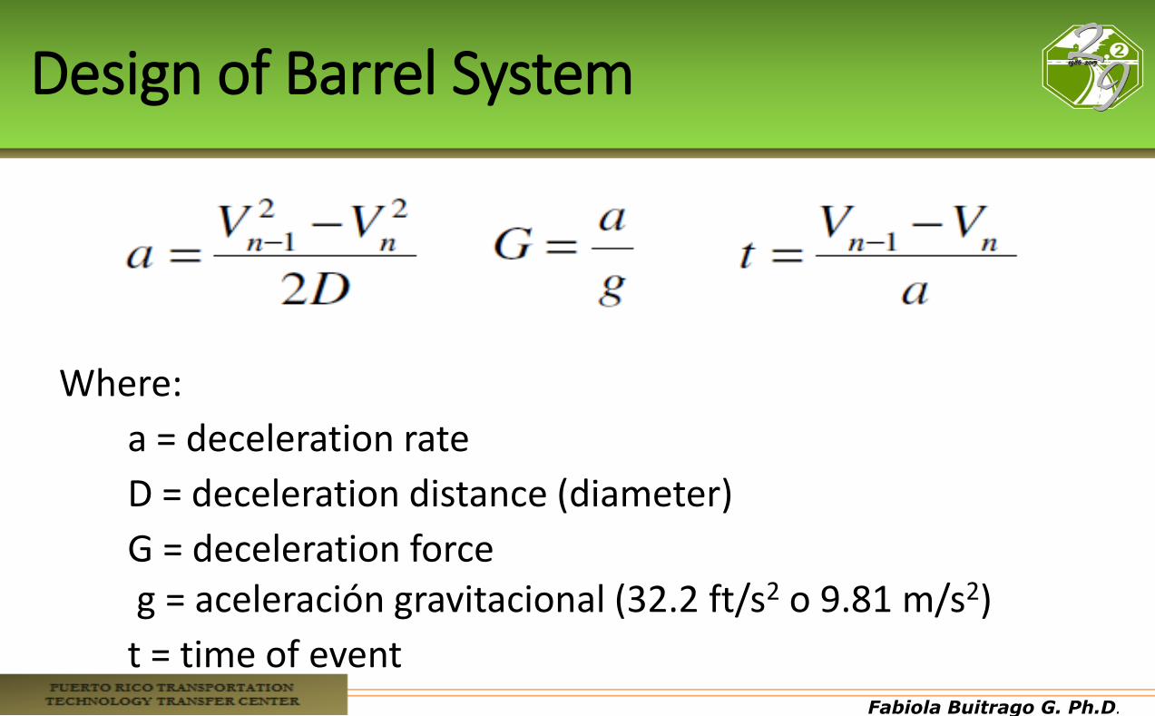
Design of Barrel System
Where:
a = deceleration rate
D = deceleration distance (diameter)
G = deceleration force g = aceleración gravitacional (32.2 ft/s2 o 9.81 m/s2)
t = time of event
Fabiola Buitrago G. Ph.D.
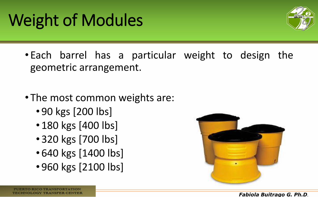
Weight of Modules
•Each barrel has a particular weight to design the geometric arrangement.
•The most common weights are: •90 kgs [200 lbs] •180 kgs [400 lbs] •320 kgs [700 lbs] •640 kgs [1400 lbs] •960 kgs [2100 lbs]
Fabiola Buitrago G. Ph.D.
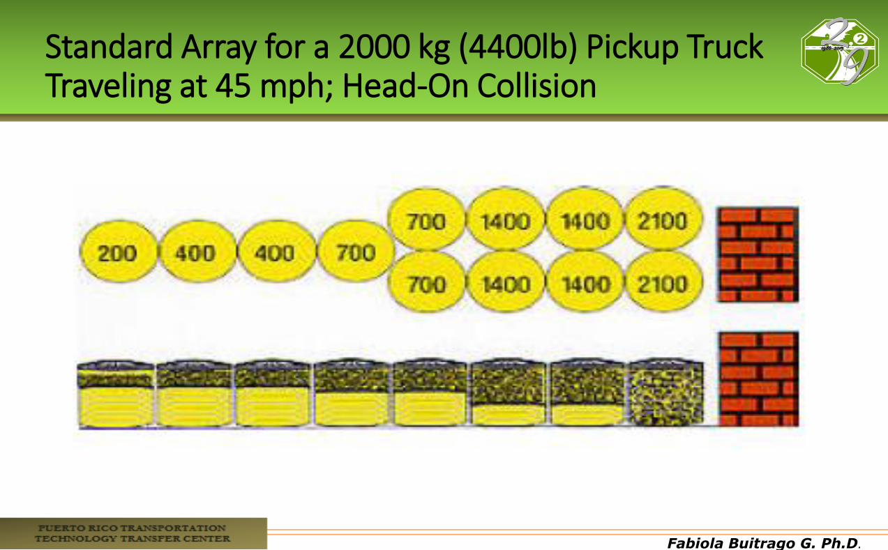
Standard Array for a 2000 kg (4400lb) Pickup Truck Traveling at 45 mph; Head-On Collision
Fabiola Buitrago G. Ph.D.
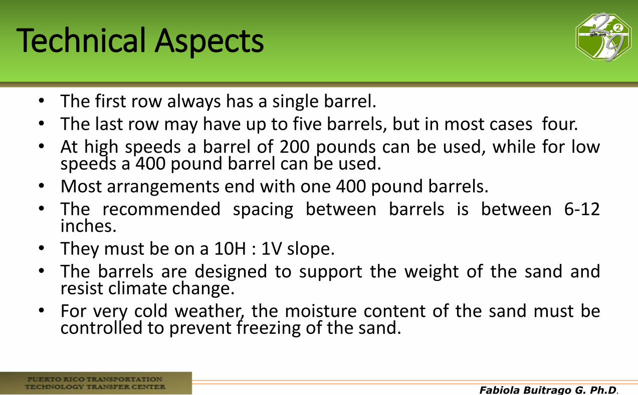
Technical Aspects
• The first row always has a single barrel. • The last row may have up to five barrels, but in most cases four. • At high speeds a barrel of 200 pounds can be used, while for low
speeds a 400 pound barrel can be used. • Most arrangements end with one 400 pound barrels. • The recommended spacing between barrels is between 6-12
inches. • They must be on a 10H : 1V slope. • The barrels are designed to support the weight of the sand and
resist climate change. • For very cold weather, the moisture content of the sand must be
controlled to prevent freezing of the sand.
Fabiola Buitrago G. Ph.D.
Technical Aspects
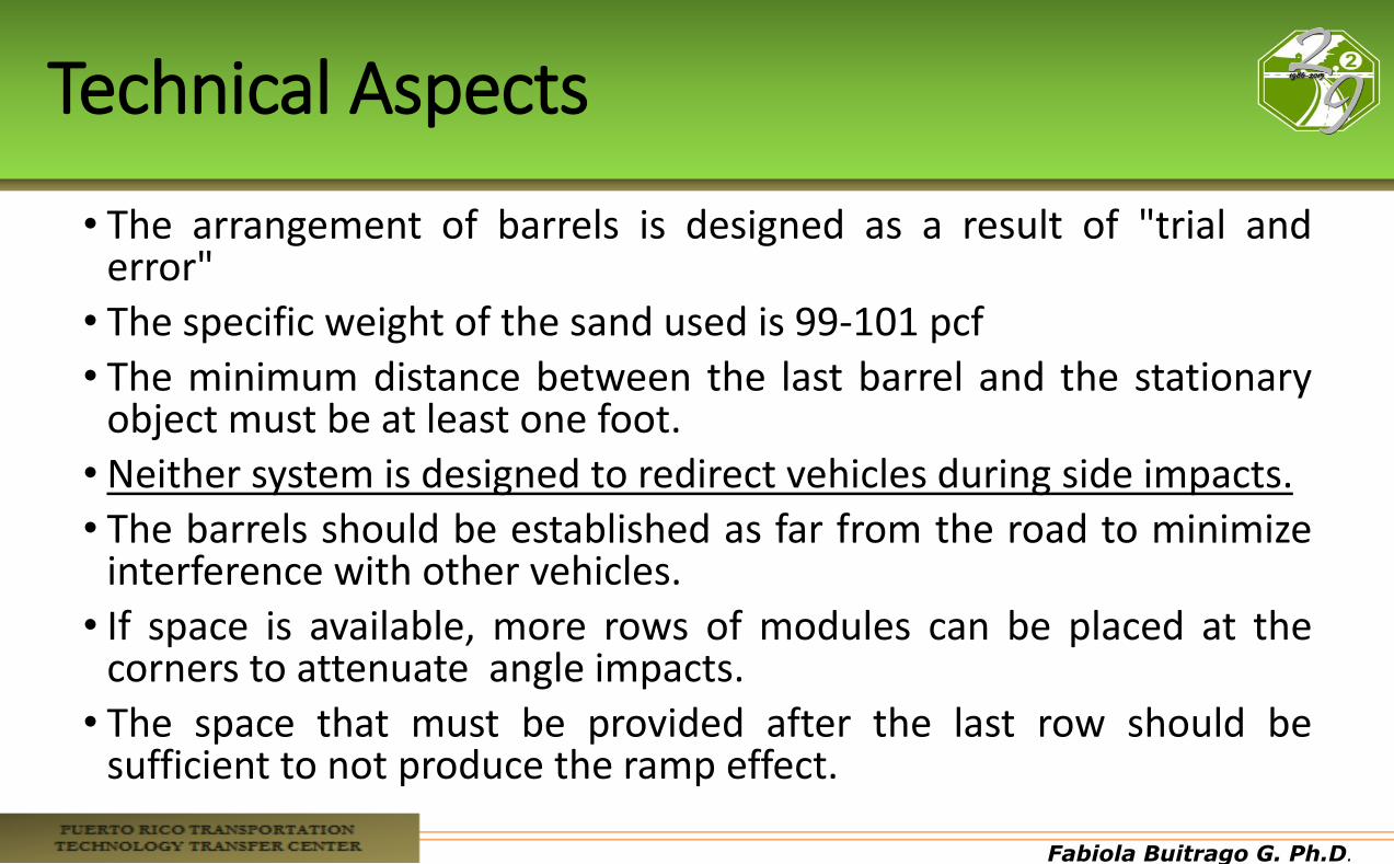
• The arrangement of barrels is designed as a result of "trial and error"
• The specific weight of the sand used is 99-101 pcf
• The minimum distance between the last barrel and the stationary object must be at least one foot.
• Neither system is designed to redirect vehicles during side impacts.
• The barrels should be established as far from the road to minimize interference with other vehicles.
• If space is available, more rows of modules can be placed at the corners to attenuate angle impacts.
• The space that must be provided after the last row should be sufficient to not produce the ramp effect.
Fabiola Buitrago G. Ph.D.
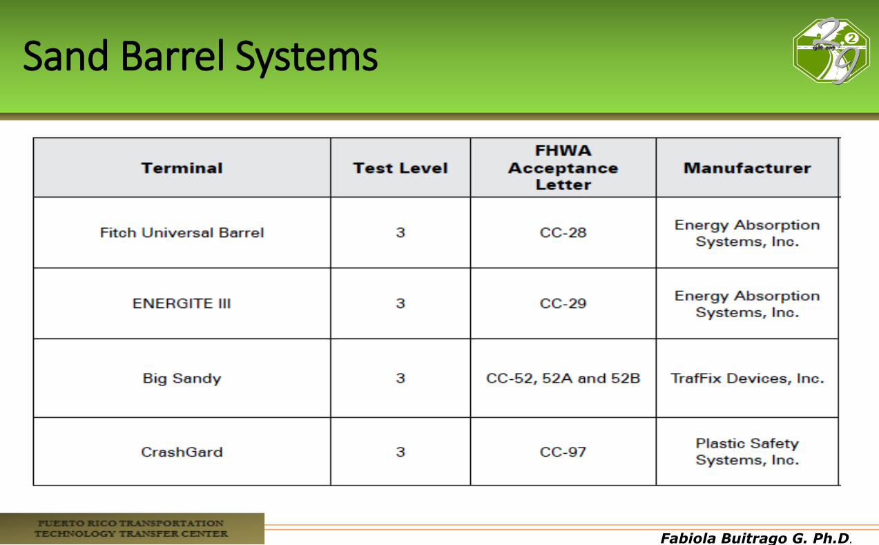
Sand Barrel Systems

Fabiola Buitrago G. Ph.D.
Fabiola Buitrago G. Ph.D.
Fabiola Buitrago G. Ph.D.
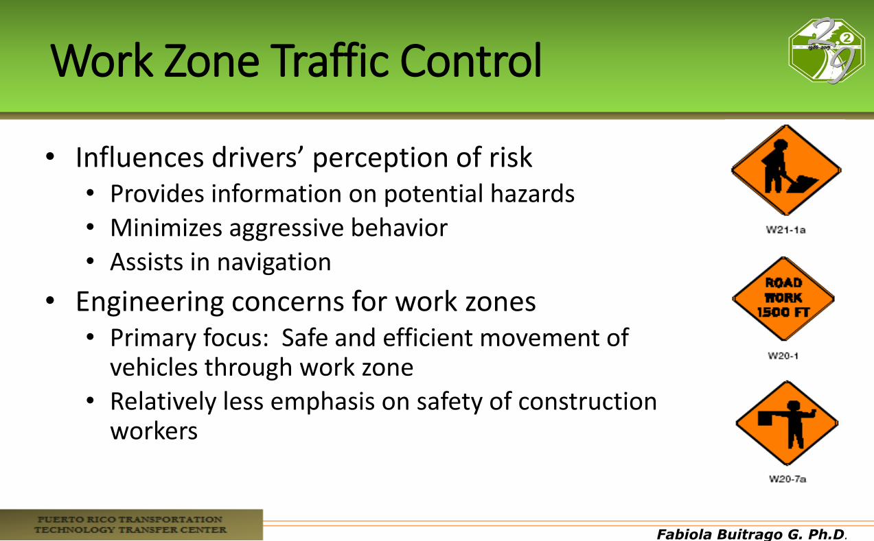
Work Zone Traffic Control
• Influences drivers’ perception of risk • Provides information on potential hazards • Minimizes aggressive behavior • Assists in navigation
• Engineering concerns for work zones • Primary focus: Safe and efficient movement of
vehicles through work zone • Relatively less emphasis on safety of construction
workers
Fabiola Buitrago G. Ph.D.
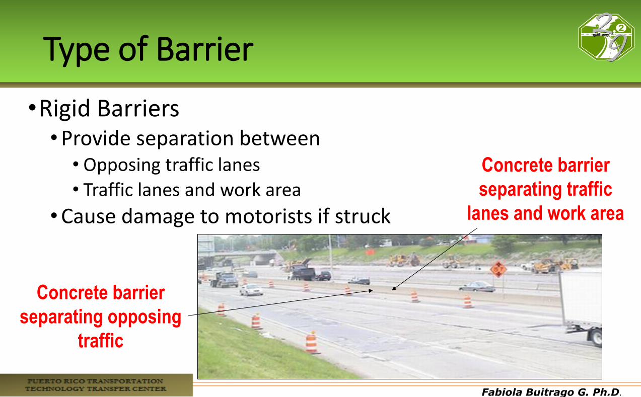
Type of Barrier
•Rigid Barriers •Provide separation between
• Opposing traffic lanes • Traffic lanes and work area
•Cause damage to motorists if struck
Concrete barrier
separating opposing
traffic
Concrete barrier
separating traffic
lanes and work area
Fabiola Buitrago G. Ph.D.
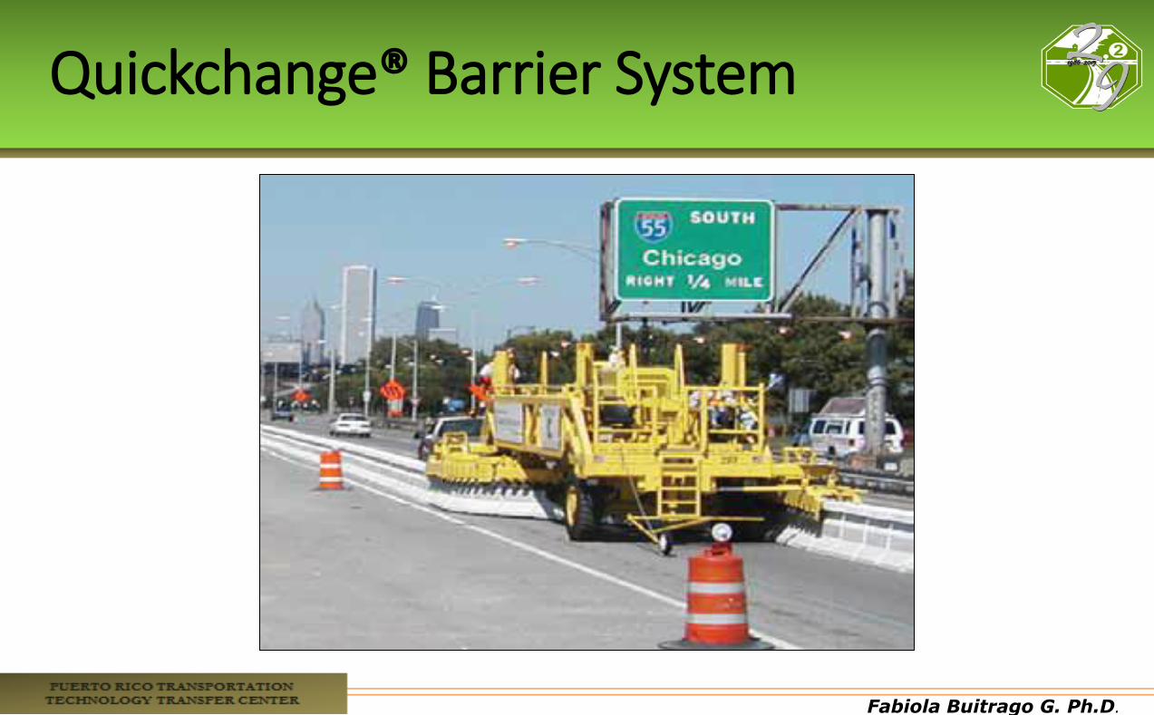
Quickchange® Barrier System
Fabiola Buitrago G. Ph.D.
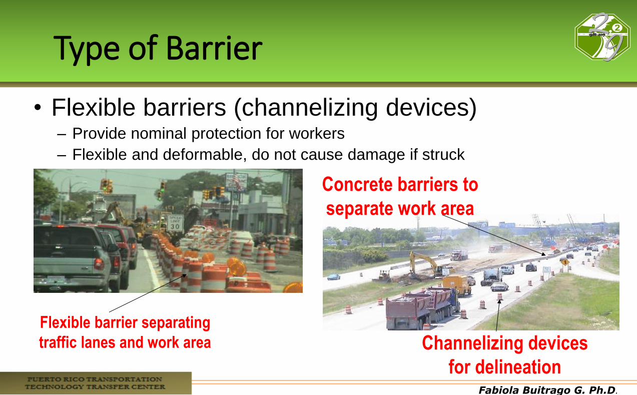
Type of Barrier
• Flexible barriers (channelizing devices) – Provide nominal protection for workers
– Flexible and deformable, do not cause damage if struck
Flexible barrier separating
traffic lanes and work area Channelizing devices
for delineation
Concrete barriers to
separate work area
Fabiola Buitrago G. Ph.D.
MUTCD: Manual on Uniform Traffic Control Devices
•Recognized as the national standard
•Enforcement agencies often adopt it by reference
•Provides guidance, options and supporting materials • To assist professionals in making
decisions regarding the use of traffic control on streets and highways
Fabiola Buitrago G. Ph.D.
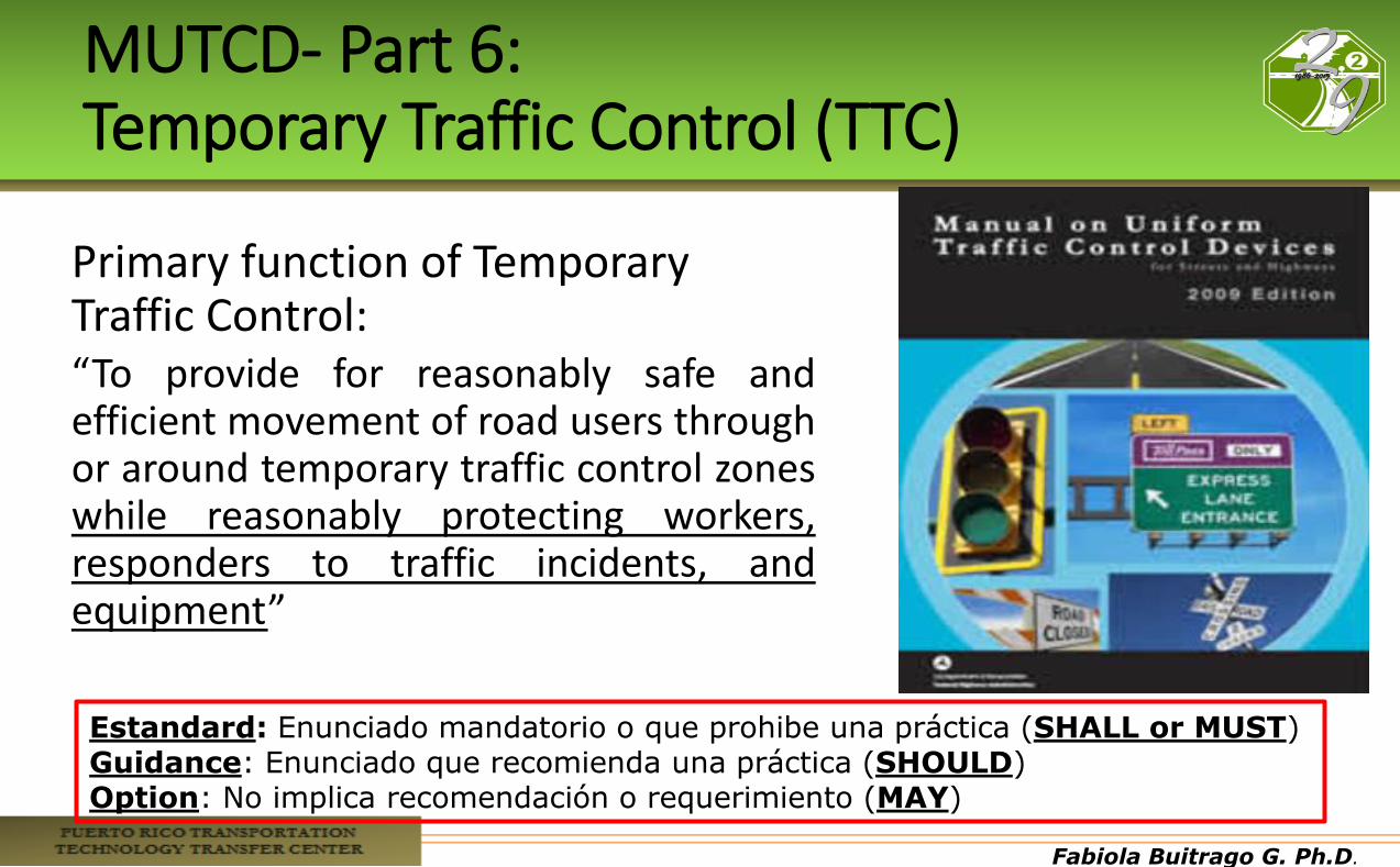
MUTCD- Part 6: Temporary Traffic Control (TTC)
Primary function of Temporary Traffic Control: “To provide for reasonably safe and efficient movement of road users through or around temporary traffic control zones while reasonably protecting workers, responders to traffic incidents, and equipment”
Estandard: Enunciado mandatorio o que prohibe una práctica (SHALL or MUST) Guidance: Enunciado que recomienda una práctica (SHOULD) Option: No implica recomendación o requerimiento (MAY)
Fabiola Buitrago G. Ph.D.
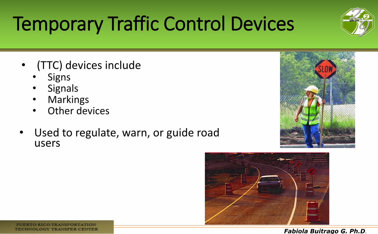
Temporary Traffic Control Devices
• (TTC) devices include • Signs • Signals • Markings • Other devices
• Used to regulate, warn, or guide road users

Fabiola Buitrago G. Ph.D.
Types of TTC Applications
•Each TTC zone is different
•Many variables affect the needs of each zone: • Location of work •Duration of work •Highway type •Geometrics
• Vertical and horizontal alignment, intersections, interchanges, etc.
• Road user volumes • Road vehicle mix (buses, trucks, and cars) and road user speeds
Fabiola Buitrago G. Ph.D.
Work Duration
• Main factor in determining the number and types of devices used in TTC zones
• As per the MUTCD, five categories of work duration are defined:
1. Long-term stationary 2. Intermediate-term stationary 3. Short-term stationary 4. Short duration 5. Mobile
Fabiola Buitrago G. Ph.D.
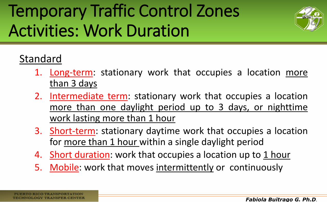
Temporary Traffic Control Zones Activities: Work Duration
Standard 1. Long-term: stationary work that occupies a location more
than 3 days 2. Intermediate term: stationary work that occupies a location
more than one daylight period up to 3 days, or nighttime work lasting more than 1 hour
3. Short-term: stationary daytime work that occupies a location for more than 1 hour within a single daylight period
4. Short duration: work that occupies a location up to 1 hour 5. Mobile: work that moves intermittently or continuously

Fabiola Buitrago G. Ph.D.
TTC Through Traffic Incident Management Areas
Traffic incidents can be divided into three general classes of duration, each of which has unique traffic control characteristics and needs:
• Major: expected duration of more than 2 hours • Intermediate: expected duration of 30 minutes to 2 hours • Minor: expected duration under 30 minutes
Fabiola Buitrago G. Ph.D.
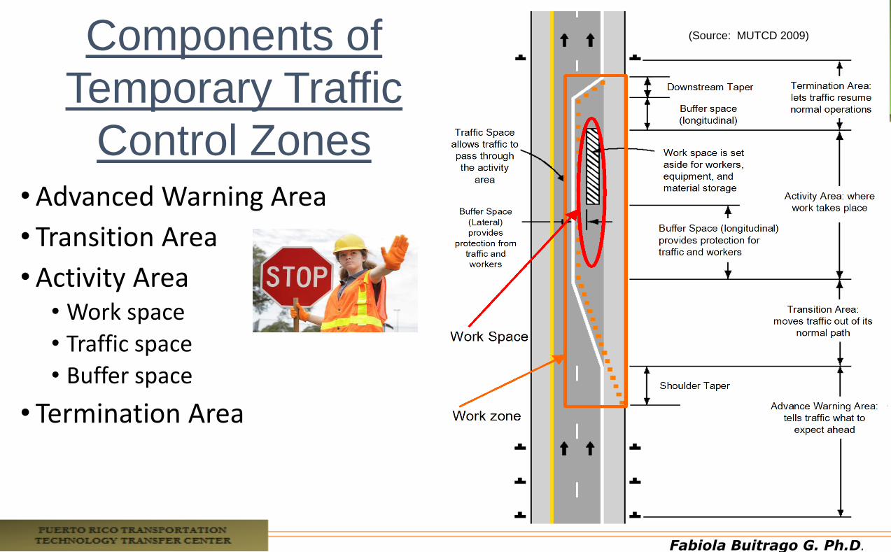
Components of
Temporary Traffic
Control Zones
(Source: MUTCD 2009)
•Advanced Warning Area
• Transition Area
•Activity Area • Work space
• Traffic space
• Buffer space
• Termination Area
Fabiola Buitrago G. Ph.D.
Fabiola Buitrago G. Ph.D.