Embed Size (px)
Citation preview
Introduction 1-1
Welcome to CSCI 547 Computer Networks
The lecture materials: Syllabus, Powerpoint Notes, Homeworks, Project specification are available both on Vista ( http://online2.csuchico.edu ) and http://www.ecst.csuchico.edu/~sim ). They will be synchronized (I will try my best to keep them identical).Please notify me if you find any discrepancy between them.Homeworks must be handed in via VistaMy email addresses are: [email protected] or [email protected] My office phone number is (530) 898-5056Seung Bae ImProfessorDept. of Computer ScienceCalifornia State University, Chico95929

Introduction 1-2
Chapter 1Introduction
Computer Networking: A Top Down Approach ,4th edition. Jim Kurose, Keith RossAddison-Wesley, July 2007.
A note on the use of these ppt slides:We’re making these slides freely available to all (faculty, students, readers). They’re in PowerPoint form so you can add, modify, and delete slides (including this one) and slide content to suit your needs. They obviously represent a lot of work on our part. In return for use, we only ask the following: If you use these slides (e.g., in a class) in substantially unaltered form, that you mention their source (after all, we’d like people to use our book!) If you post any slides in substantially unaltered form on a www site, that you note that they are adapted from (or perhaps identical to) our slides, and note our copyright of this material.
Thanks and enjoy! JFK/KWR
All material copyright 1996-2007J.F Kurose and K.W. Ross, All Rights Reserved
Introduction 1-3
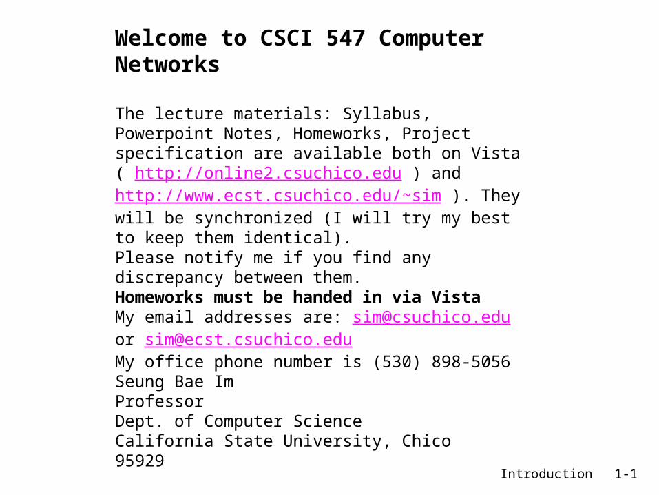
Top-down vs Bottom-up
OSI 7 layer model
AnalogyTextbook’s approach Traditional approach

Introduction 1-4
Chapter 1: IntroductionOur goal: get “feel” and
terminology more depth, detail
later in course approach:
use Internet as example
Overview: what’s the Internet? what’s a protocol? network edge; hosts, access
net, physical media network core: packet/circuit
switching, Internet structure performance: loss, delay,
throughput security protocol layers, service
models history
Introduction 1-5
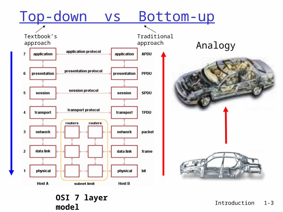
Chapter 1: roadmap
1.1 What is the Internet?1.2 Network edge
end systems, access networks, links
1.3 Network core circuit switching, packet switching, network
structure
1.4 Delay, loss and throughput in packet-switched networks
1.5 Protocol layers, service models1.6 Networks under attack: security1.7 History
Introduction 1-6
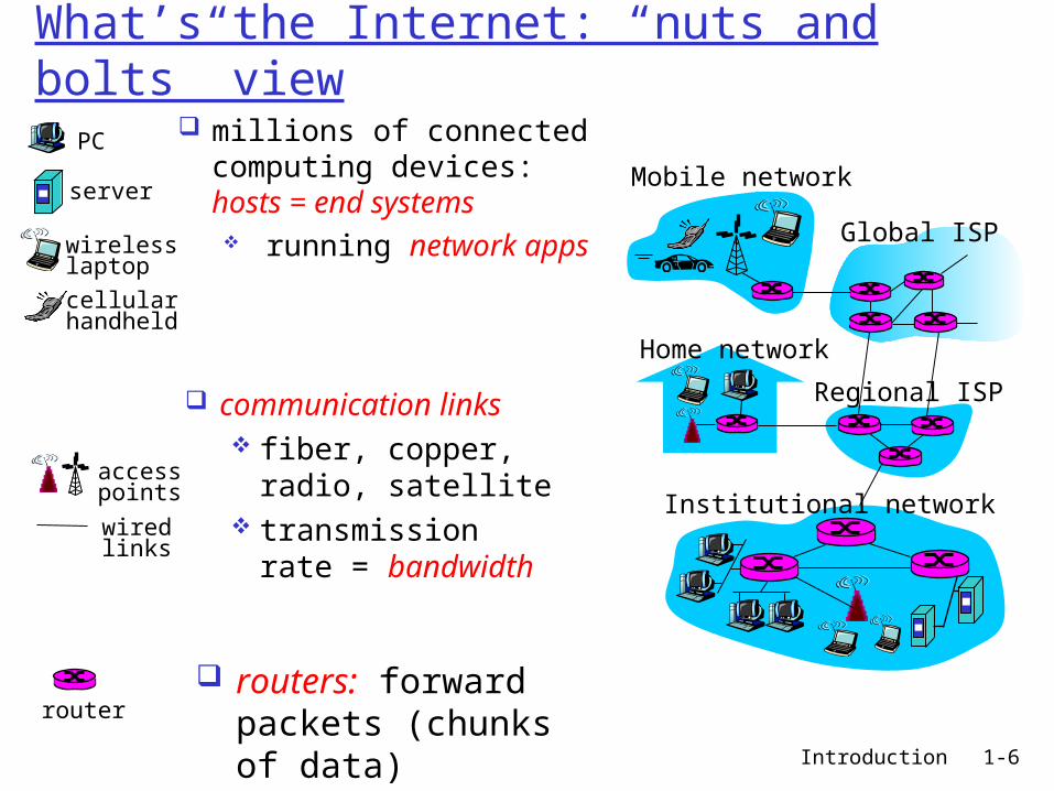
What’s the Internet: “nuts and bolts” view
millions of connected computing devices: hosts = end systems running network
appsHome network
Institutional network
Mobile network
Global ISP
Regional ISP
router
PC
server
wirelesslaptop
cellular handheld
wiredlinks
access points
communication links fiber, copper,
radio, satellite transmission rate
= bandwidth
routers: forward packets (chunks of data)

Introduction 1-7
“Cool” internet appliances
World’s smallest web serverhttp://www-ccs.cs.umass.edu/~shri/iPic.html
IP picture framehttp://www.ceiva.com/
Web-enabled toaster +weather forecaster
Internet phones
Internet refrigerator

Introduction 1-8
What’s the Internet: “nuts and bolts” view protocols control sending,
receiving of msgs e.g., TCP, IP, HTTP, Skype,
Ethernet
Internet: “network of networks” loosely hierarchical public Internet versus
private intranet
Internet standards RFC: Request for comments IETF: Internet Engineering
Task Force http://www.ietf.org/
Defined in RFC: Request For Comments
Home network
Institutional network
Mobile network
Global ISP
Regional ISP

Introduction 1-9
What’s the Internet: a service view communication
infrastructure enables distributed applications: Web, VoIP, email,
games, e-commerce, file sharing, video chatting,
communication services provided to apps: reliable data delivery
from source to destination
“best effort” (unreliable) data delivery
cyberspace [Gibson]:“a consensual hallucination experienced daily by billions of operators, in every
nation, ...."

Introduction 1-10
What’s a protocol?
human protocols: “what’s the time?” “I have a question” introductions
… specific msgs sent… specific actions
taken when msgs received, or other events
network protocols: machines rather than
humans all communication
activity in Internet governed by protocols
protocols define format, order of msgs sent and
received among network entities, and actions taken on msg transmission, receipt
Introduction 1-11
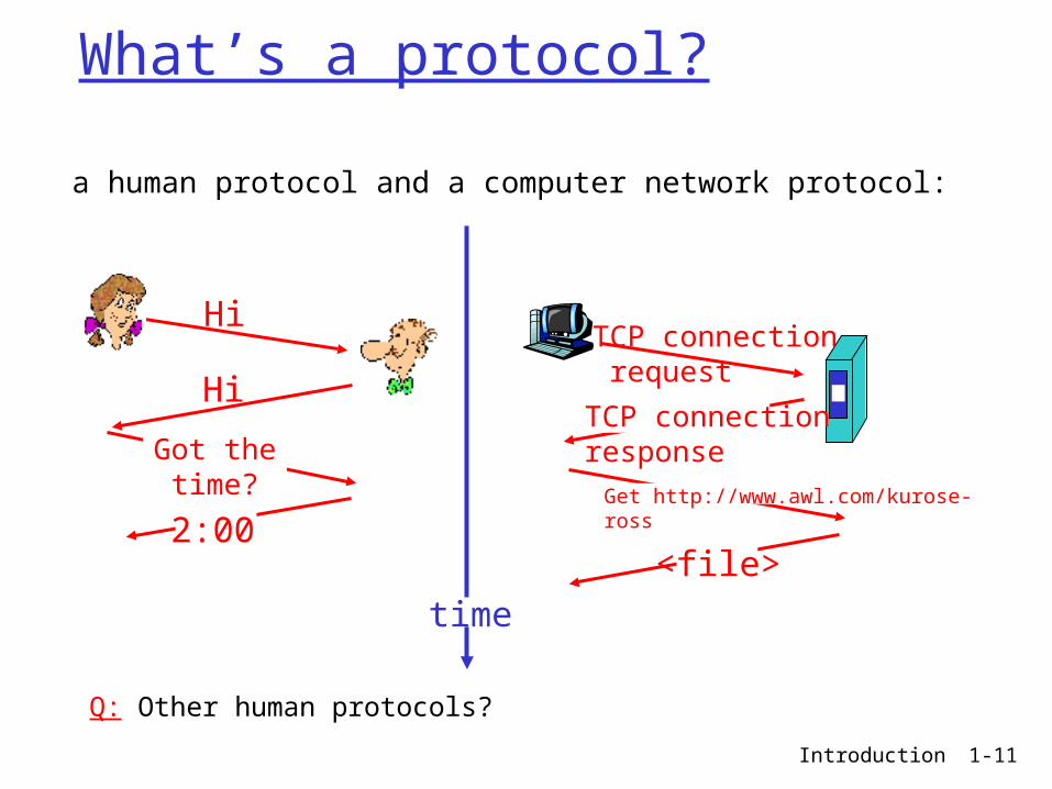
What’s a protocol?
a human protocol and a computer network protocol:
Q: Other human protocols?
Hi
Hi
Got thetime?
2:00
TCP connection request
TCP connectionresponseGet http://www.awl.com/kurose-ross
<file>time

Introduction 1-12
Definition of Protocol
Strict rules that govern the communication between communicating entities.
Rule1: Originating entity should say “Hello”Rule2: If you get a reply “Hello” back, Then
say “How are you?” Else Repeat Rule1
Rule3: etc. etc. …….
We need “standard protocols” that are defined by “standard organizations”

Introduction 1-13
Standard organizations
Read http://en.wikipedia.org/wiki/Standards_Organizations
Can be classified into:1) National level organizations2) Regional level organizations3) International level organizationsLet’s look at the major players

Introduction 1-14
National level standards orga.Can be either:
Governmental organizations —ex. NIST (National Institute of Standards and Technology) in US
Quasi-governmental —ex. BSI (British Standards Institute)
Non-governmental (usually non-profit) —ex. ANSI (American Nat’l Standards Institute), EIA/TIA
Introduction 1-15
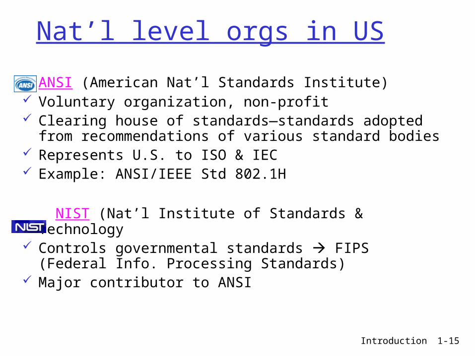
Nat’l level orgs in US
ANSI (American Nat’l Standards Institute) Voluntary organization, non-profit Clearing house of standards—standards adopted
from recommendations of various standard bodies Represents U.S. to ISO & IEC Example: ANSI/IEEE Std 802.1H
NIST (Nat’l Institute of Standards & Technology Controls governmental standards FIPS (Federal
Info. Processing Standards) Major contributor to ANSI

Introduction 1-16
Nat’l level orgs in US—cont’d EIA (Electronic Industries Alliance )
Manufacturers’ trade organization TIA (Telecommunications Industry Association) is a
sector of EIA Recommends standards to ANSI, ISO, IEC Ex. EIA RS232D, EIA/TIA 568(UTP cabling standard)
IEEE (Institute of Electrical and Electronics Engineers )
World's leading professional association Pseudo-standard organization IEEE 802 LAN standards ANSI 802 ISO 8802

Introduction 1-17
Nat’l level in other countries
Introduction 1-18
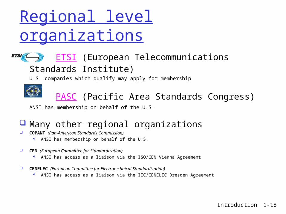
Regional level organizations
ETSI (European Telecommunications Standards Institute)
U.S. companies which qualify may apply for membership
PASC (Pacific Area Standards Congress)ANSI has membership on behalf of the U.S.
Many other regional organizations COPANT (Pan-American Standards Commission)
ANSI has membership on behalf of the U.S.
CEN (European Committee for Standardization) ANSI has access as a liaison via the ISO/CEN Vienna Agreement
CENELEC (European Committee for Electrotechnical Standardization) ANSI has access as a liaison via the IEC/CENELEC Dresden Agreement
Introduction 1-19
International level orgs
ISO (International Standards Organization) Voluntary, non-treaty Membership—Nat’l standard organizations—ANSI OSI model (ISO 7498) Concentrates on Computer comm. & higher layers of
OSI
ITU-T (International Telecommunications Union-Telecommunications Standardization Sector)
Formerly known as CCITT Treaty organization—(under UN) Membership by country—State Dept represents US Concentrates on Telecomm. & lower layers of OSICross-adopted & Overlapping standards: ex. ISO7498(OSI model) = ITU-T X.200

Introduction 1-20
International level orgs—cont’d
IEC (International Electrotechnical Commision)—concentrates on electrical, electronic and related technologies ISOC (Internet Society)—Internet standardsIEEE (Institute of Electrical and Electronics Engineers)—heavy contribution on LAN standards IEEE is listed both in national level and
international level

Introduction 1-21
Industry consortia & forums
Newer force in standardization—gathering of manufacturers & implementers
To speed up standardization To implement quickly to avoid obsolescence
of technologies—technologies can’t wait for Nat’l/Regional/Int’l standards
EX. World Wide Web Consortium (W3C) http://www.wapforum.org/ DSL Forum, WAP Forum, MFA Forum,
IPv6 Forum …
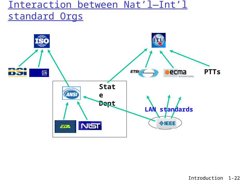
Introduction 1-22
Interaction between Nat’l—Int’l standard Orgs
State Dept
PTTs
LAN standards

Introduction 1-23
Internet standards
ISOC (Internet Society)
IRTF
(Internet Research Task Force)—Focuses on research
IETF
(Internet Engineering Task Force) —Responsible for creating Internet standards ( RFCs )
IAB (Internet Architecture Board)
For detailed information for the Internet organizations, visit http://www.acm.org/ubiquity/views/v6i5_simoneli.html
IESG IRSG

Introduction 1-24
Internet standards—Cont’d
ICANN
W3C(World Wide Web Consortium)
W3C is responsible for WWW standards
Internet Assigned Numbers Authority
The Internet Corporation for Assigned Names and Numbers (ICANN) is an internationally organized, non-profit corporation that has responsibility for Internet Protocol (IP) address space allocation, protocol identifier assignment, generic (gTLD) and country code (ccTLD) Top-Level Domain name system management, and root server system management functions.
Under ICANN and mainly responsible for IP addresses & Protocol numbers
Introduction 1-25
Chapter 1: roadmap
1.1 What is the Internet?1.2 Network edge
end systems, access networks, links
1.3 Network core circuit switching, packet switching, network
structure
1.4 Delay, loss and throughput in packet-switched networks
1.5 Protocol layers, service models1.6 Networks under attack: security1.7 History

Introduction 1-26
A closer look at network structure: network edge:
applications and hosts
access networks, physical media: wired, wireless communication links network core:
interconnected routers
network of networks
Introduction 1-27
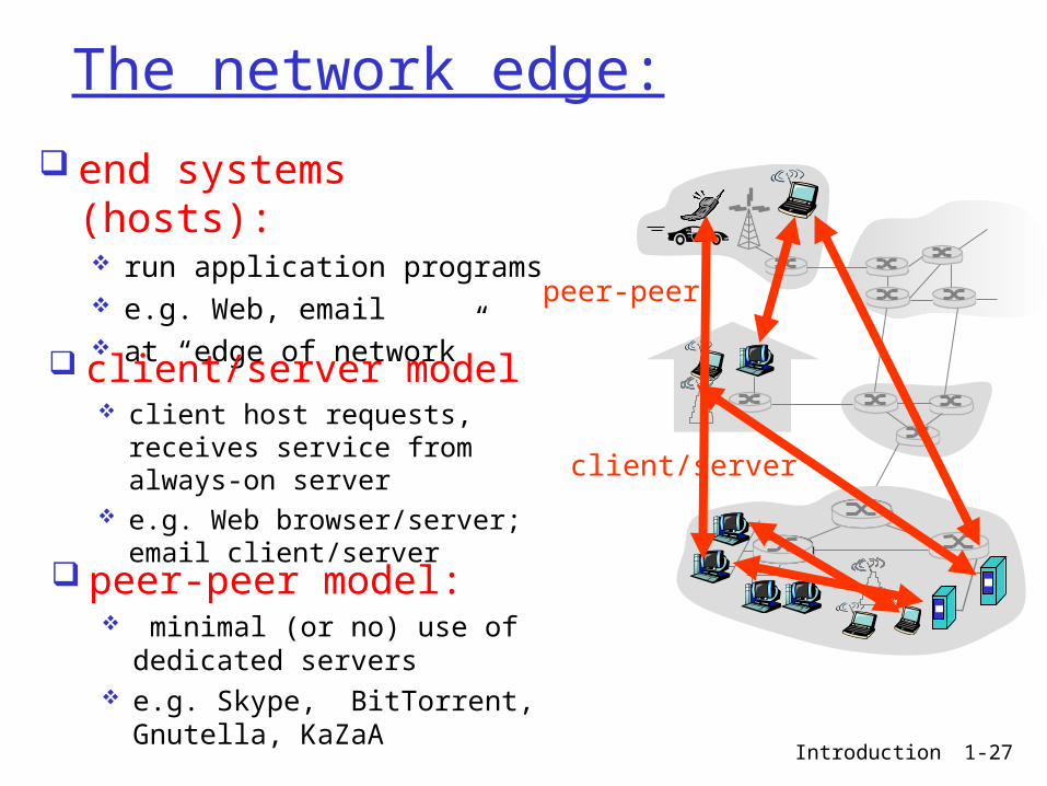
The network edge:
end systems (hosts): run application programs e.g. Web, email at “edge of network”
client/server
peer-peer
client/server model client host requests, receives
service from always-on server e.g. Web browser/server;
email client/server
peer-peer model: minimal (or no) use of
dedicated servers e.g. Skype, BitTorrent,
Gnutella, KaZaA

Introduction 1-28
Access networks and physical media
Q: How to connect end systems to edge router?
residential access nets institutional access
networks (school, company)
mobile access networks
Keep in mind: bandwidth (bits per
second) of access network?
shared or dedicated?

Introduction 1-29
Residential access: point to point access
Dialup via modem up to 56Kbps direct access
to router (often less) Can’t surf and phone at
same time: can’t be “always on”
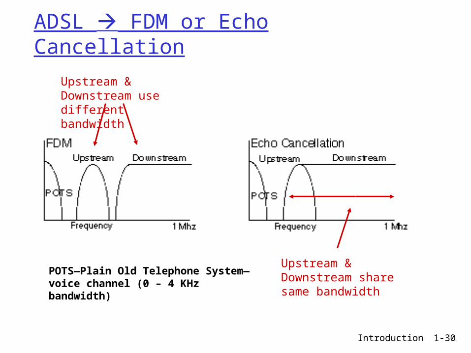
DSL: digital subscriber line—most popular is ADSL: Asymmetric Digital Subscriber Loop deployment: telephone company (typically) up to 1 Mbps upstream (today typically < 256 kbps) up to 8 Mbps downstream (today typically < 1 Mbps) dedicated physical line to telephone central office
Introduction 1-30
ADSL FDM or Echo Cancellation
POTS—Plain Old Telephone System—voice channel (0 – 4 KHz bandwidth)
Upstream & Downstream use different bandwidth
Upstream & Downstream share same bandwidth

Introduction 1-31
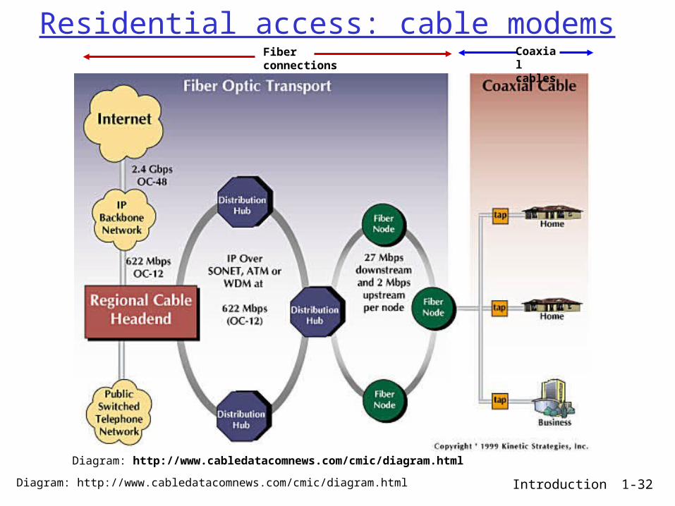
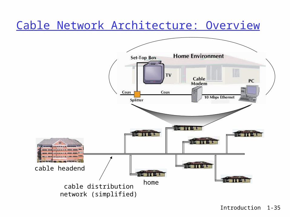
Residential access: cable modems
HFC: hybrid fiber coax Fiber to a neighborhood of 100-2000
homes Coax to each home asymmetric: up to 30Mbps downstream, 2
Mbps upstream network of cable and fiber attaches homes to
ISP router homes share access to router
deployment: available via cable TV companies since 1990s
Introduction 1-32
Residential access: cable modems
Diagram: http://www.cabledatacomnews.com/cmic/diagram.html
Fiber connections
Coaxial cables
Diagram: http://www.cabledatacomnews.com/cmic/diagram.html
Introduction 1-33
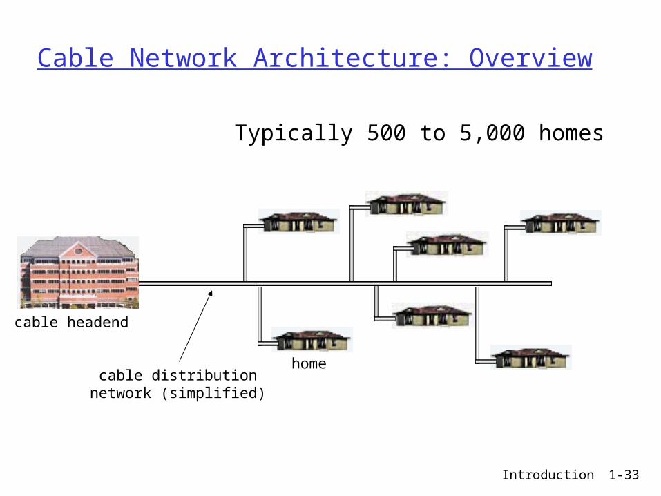
Cable Network Architecture: Overview
home
cable headend
cable distributionnetwork (simplified)
Typically 500 to 5,000 homes
Introduction 1-34
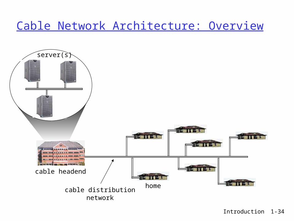
Cable Network Architecture: Overview
home
cable headend
cable distributionnetwork
server(s)
Introduction 1-35
Cable Network Architecture: Overview
home
cable headend
cable distributionnetwork (simplified)

Introduction 1-36
Cable Network Architecture: Overview
home
cable headend
cable distributionnetwork
Channels
VIDEO
VIDEO
VIDEO
VIDEO
VIDEO
VIDEO
DATA
DATA
CONTROL
1 2 3 4 5 6 7 8 9
FDM (more shortly):
Introduction 1-37
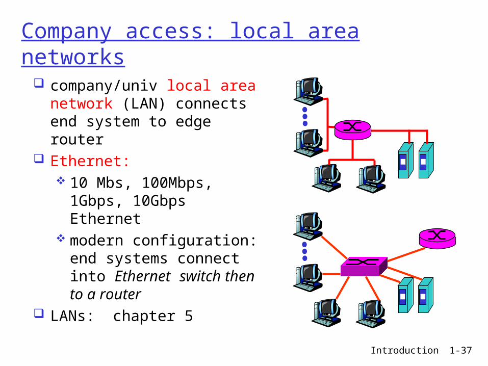
Company access: local area networks
company/univ local area network (LAN) connects end system to edge router
Ethernet: 10 Mbs, 100Mbps,
1Gbps, 10Gbps Ethernet
modern configuration: end systems connect into Ethernet switch then to a router
LANs: chapter 5

Introduction 1-38
Wireless access networks
shared wireless access network connects end system to router via base station aka “access
point” wireless LANs:
802.11b/g (WiFi): 11 or 54 Mbps
wider-area wireless access provided by telco operator ~1Mbps over cellular system
(EVDO, HSDPA) next up (?): WiMax (10’s
Mbps) over wide area WAP / GPRS in Europe
basestation
mobilehosts
router
Introduction 1-39
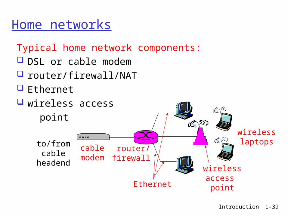
Home networks
Typical home network components: DSL or cable modem router/firewall/NAT Ethernet wireless access point
wirelessaccess point
wirelesslaptops
router/firewall
cablemodem
to/fromcable
headend
Ethernet
Introduction 1-40
Physical Media
Bit: propagates betweentransmitter/rcvr pairs
physical link: what lies between transmitter & receiver
guided media: signals propagate in solid
media: copper, fiber, coax
unguided media: signals propagate freely
through space, e.g., radio, microwave, infrared, laser

Introduction 1-41
Physical media connections
Introduction 1-42
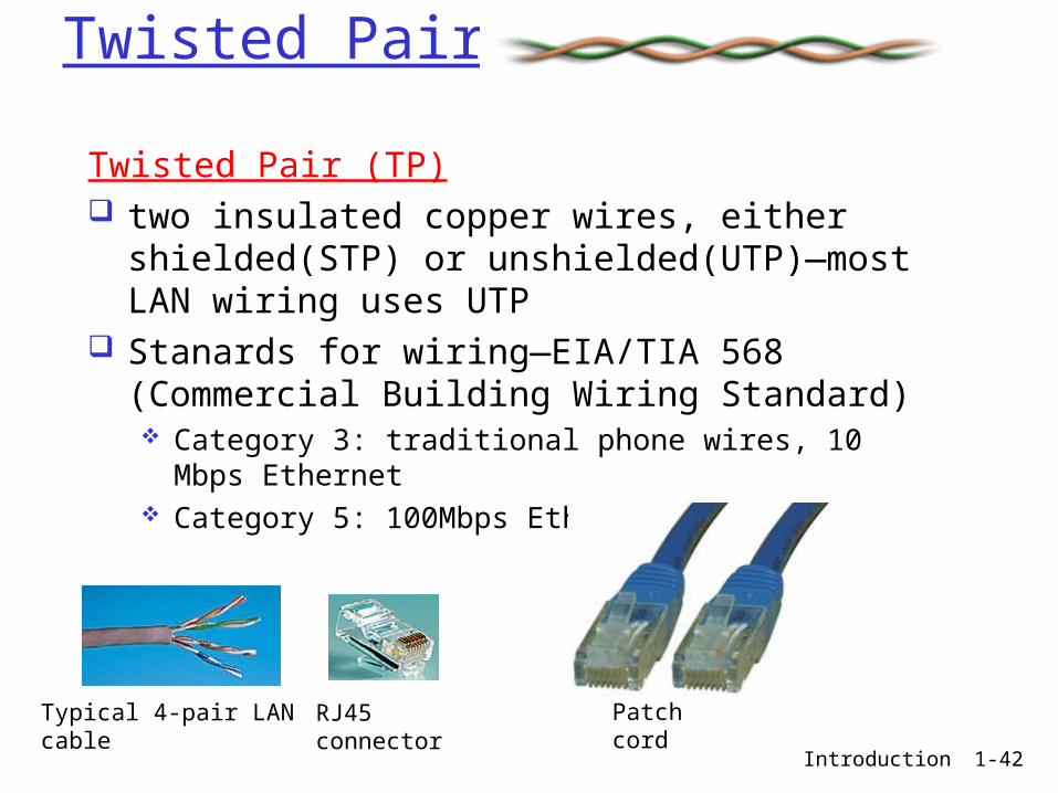
Twisted Pairs
Twisted Pair (TP) two insulated copper wires, either
shielded(STP) or unshielded(UTP)—most LAN wiring uses UTP
Stanards for wiring—EIA/TIA 568 (Commercial Building Wiring Standard) Category 3: traditional phone wires, 10 Mbps
Ethernet Category 5: 100Mbps Ethernet
Typical 4-pair LAN cable RJ45 connector Patch cord

Introduction 1-43
EIA/TIA 568
ANSI / TIA / EIA 568 Cabling Standards and LAN Applications
CAT 3 (voice grade)
CAT 5 CAT 5e CAT 6 CAT 7
Bandwidth 16MHz 100MHz 100MHz 250MHz 600MHz
Type UTP UTP/FTP UTP/FTP UTP/FTP SSTP
Data Rate &LAN Applications
16Mbps10BaseT
100Mbps100BaseT, ATM, CDDI
1000Mbps1000BaseT(GigabitEthernet)
Not specified
Not specified
Length 100 meters 100 meters 100 meters 100 meters 100 meters
Link Cost (Cat 5 =1)
0.7 1 1.2 1.5 2.2
FTP: Foil Twisted PairSSTP: Shielded Screen Twisted Pair
data gradeCAT 1 & 2 (subvoice grade)
Introduction 1-44
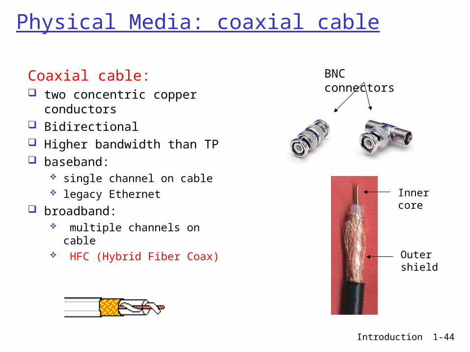
Physical Media: coaxial cable
Coaxial cable: two concentric copper
conductors Bidirectional Higher bandwidth than TP baseband:
single channel on cable legacy Ethernet
broadband: multiple channels on
cable HFC (Hybrid Fiber Coax)
BNC connectors
Inner core
Outer shield

Introduction 1-45
Physical Media: fiber optic cable
Fiber optic cable: glass fiber carrying light pulses, each pulse a bit high-speed operation:
high-speed point-to-point transmission (e.g., 10’s-100’s Gbps—almost unlimited with WDM)
low error rate: repeaters can be spaced far apart due to low attenuation
immune to electromagnetic noise
LED
Photo diode
Introduction 1-46
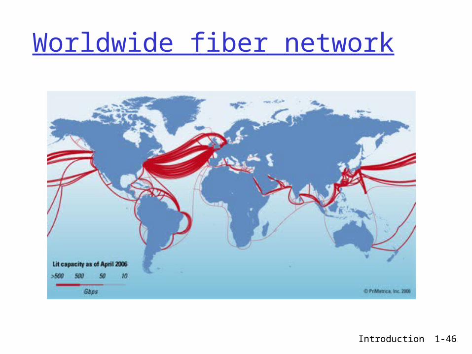
Worldwide fiber network

Introduction 1-47
Physical media: space (radio)
signal carried in electromagnetic spectrum
no physical “wire” bidirectional propagation
environment effects: reflection obstruction by objects interference
Radio link types: terrestrial microwave
e.g. up to 45 Mbps channels
LAN (e.g., Wifi) 2Mbps, 11Mbps, 54 Mbps
wide-area (e.g., cellular) e.g. 3G: hundreds of kbps
satellite Kbps to 45Mbps channel (or multiple
smaller channels) 270 msec end-end delay geosynchronous versus low orbit

Introduction 1-48
Chapter 1: roadmap
1.1 What is the Internet?1.2 Network edge
end systems, access networks, links
1.3 Network core circuit switching, packet switching, network
structure
1.4 Delay, loss and throughput in packet-switched networks
1.5 Protocol layers, service models1.6 Networks under attack: security1.7 History
Introduction 1-49
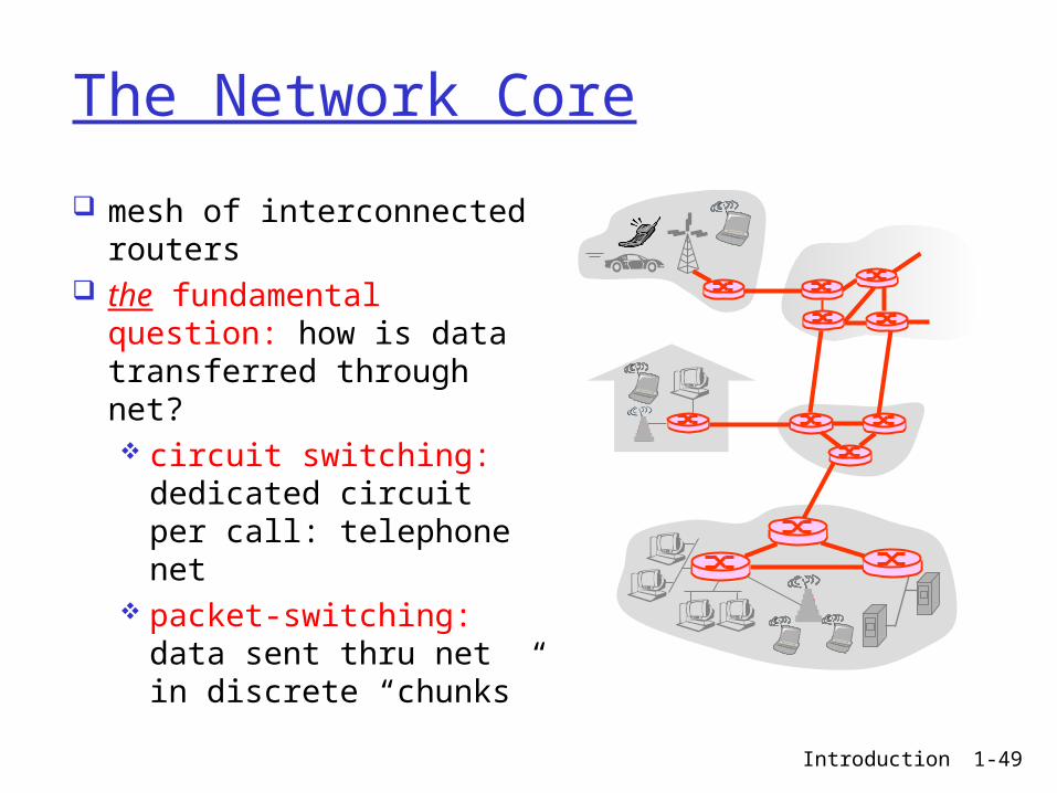
The Network Core
mesh of interconnected routers
the fundamental question: how is data transferred through net? circuit switching:
dedicated circuit per call: telephone net
packet-switching: data sent thru net in discrete “chunks”
Introduction 1-50
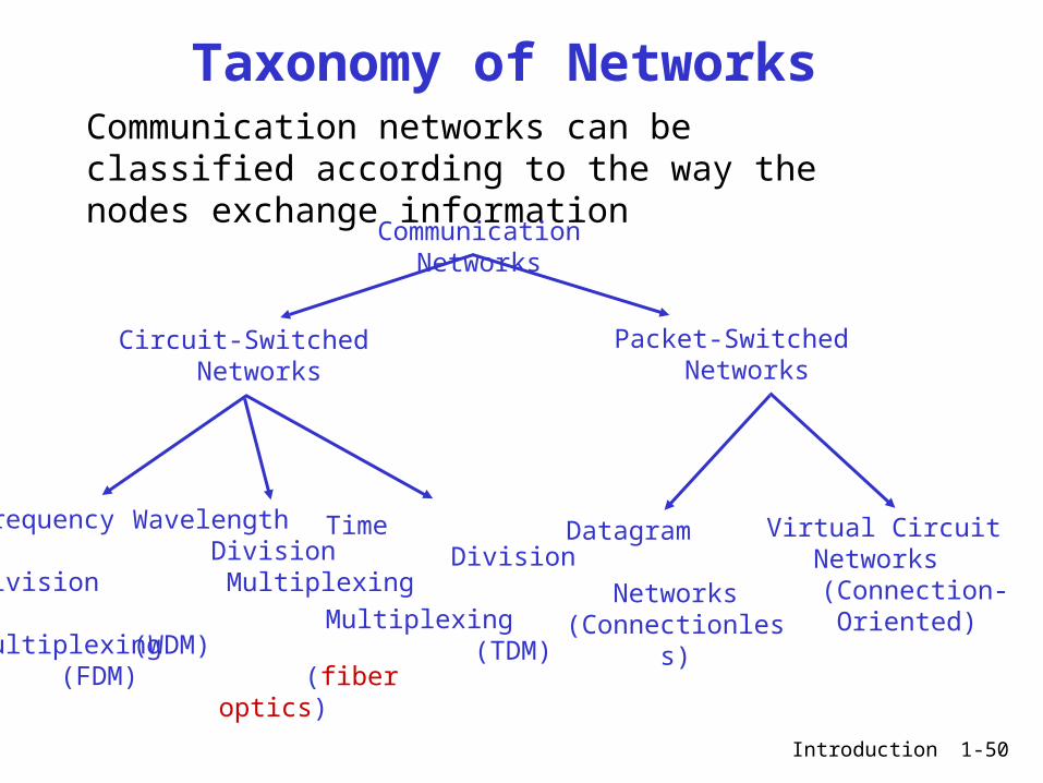
Taxonomy of NetworksCommunication networks can be classified according to the way the nodes exchange information
Communication Networks
Circuit-Switched Networks
Packet-Switched Networks
Frequency Division Multiplexing
(FDM)
Wavelength Division
Multiplexing (WDM)
(fiber optics)
Time Division
Multiplexing (TDM)
Datagram Networks
(Connectionless)
Virtual Circuit Networks
(Connection-Oriented)

Introduction 1-51
Network Core: Circuit Switching
End-end resources reserved for “call”
link bandwidth, switch capacity
dedicated resources: no sharing
circuit-like (guaranteed) performance
call setup/teardown required
Introduction 1-52
Network Core: Circuit Switching
network resources (e.g., bandwidth) divided into “pieces”
pieces allocated to calls
resource piece idle if not used by owning call (no sharing)
dividing link bandwidth into “pieces” frequency division time division

Introduction 1-53
Circuit Switching (cont’d)
Circuit-switched communication involves three phases:
1. Circuit Establishment 2. Data Transfer 3. Circuit Termination “Busy Signal” if capacity for a circuit not
available Most important circuit-switching networks:
• Telephone networks—POTS (Plain Old Telephone system)• ISDN (Integrated Services Digital Networks)

Introduction 1-54
Circuit Switching: FDM and TDM
FDM
frequency
time
TDM
frequency
time
4 users
Example:
Introduction 1-55
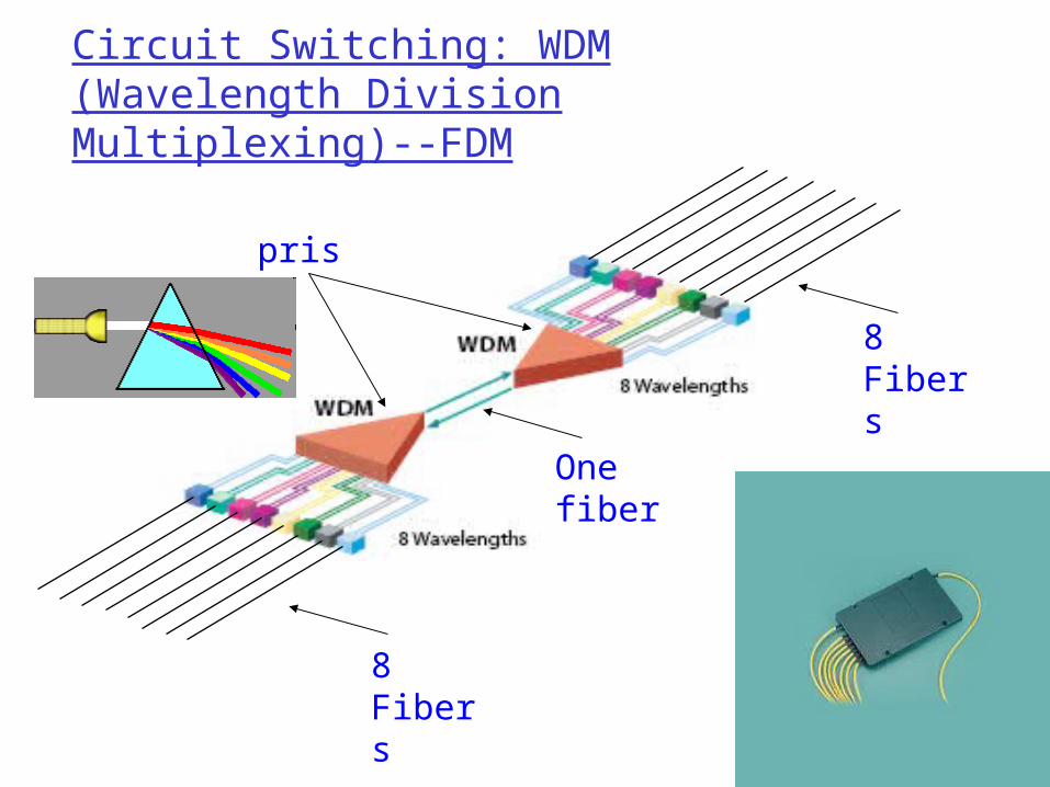
Circuit Switching: WDM(Wavelength Division Multiplexing)--FDM
8 Fibers
8 Fibers
One fiber
prisms
Introduction 1-56
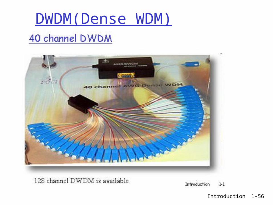
DWDM(Dense WDM)
Introduction 1-57
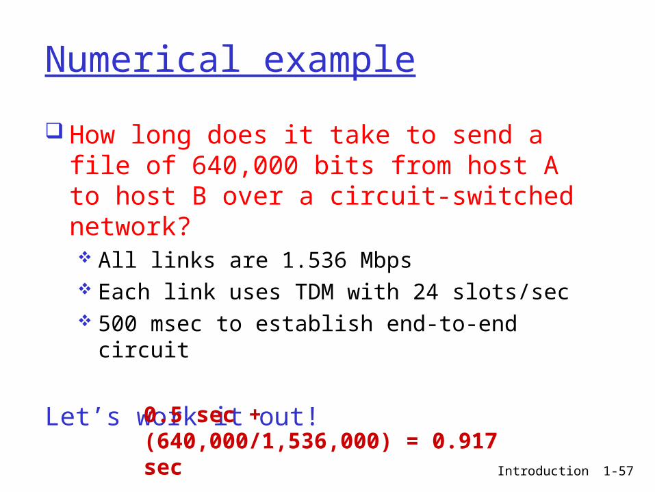
Numerical example
How long does it take to send a file of 640,000 bits from host A to host B over a circuit-switched network? All links are 1.536 Mbps Each link uses TDM with 24 slots/sec 500 msec to establish end-to-end circuit
Let’s work it out!
0.5 sec + (640,000/1,536,000) = 0.917 sec
Introduction 1-58
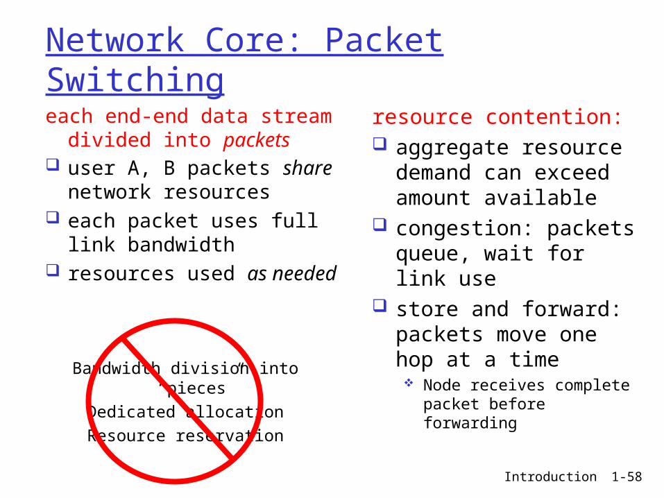
Network Core: Packet Switching
each end-end data stream divided into packets
user A, B packets share network resources
each packet uses full link bandwidth
resources used as needed
resource contention: aggregate resource
demand can exceed amount available
congestion: packets queue, wait for link use
store and forward: packets move one hop at a time Node receives complete
packet before forwarding
Bandwidth division into “pieces”Dedicated allocationResource reservation
Introduction 1-59
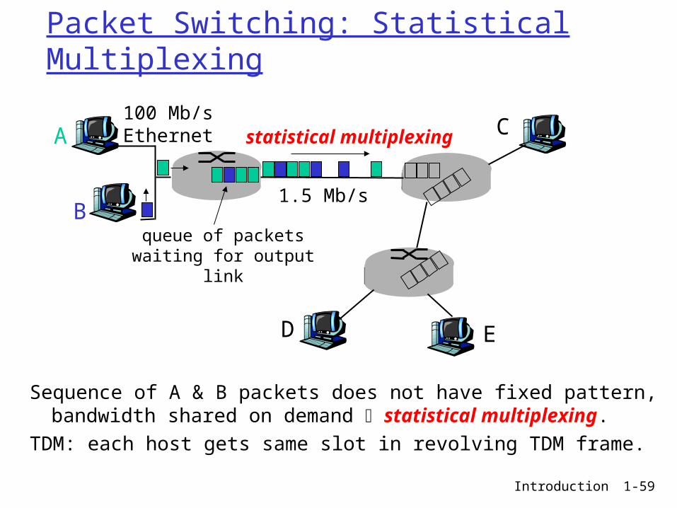
Packet Switching: Statistical Multiplexing
Sequence of A & B packets does not have fixed pattern, bandwidth shared on demand statistical multiplexing.
TDM: each host gets same slot in revolving TDM frame.
A
B
C100 Mb/sEthernet
1.5 Mb/s
D E
statistical multiplexing
queue of packetswaiting for output
link
Introduction 1-60
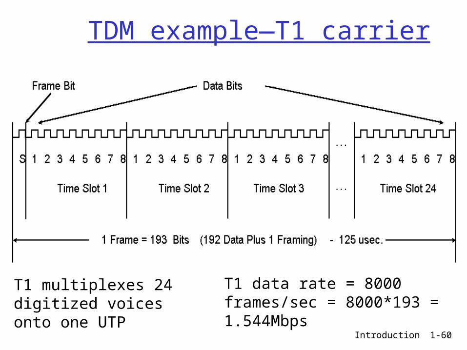
TDM example—T1 carrier
T1 multiplexes 24 digitized voices onto one UTP
T1 data rate = 8000 frames/sec = 8000*193 = 1.544Mbps

Introduction 1-61
Packet-switching: store-and-forward
takes L/R seconds to transmit (push out) packet of L bits on to link at R bps
store and forward: entire packet must arrive at router before it can be transmitted on next link
delay = 3L/R (assuming zero propagation delay)
Example: L = 7.5 Mbits R = 1.5 Mbps transmission delay =
15 sec
R R RL
more on delay shortly …

Introduction 1-62
Packet switching versus circuit switching
1 Mb/s link each user:
100 kb/s when “active”
active 10% of time
circuit-switching: 10 users
packet switching: with 35 users,
probability > 10 active at same time is less than .0004
Packet switching allows more users to use network!
N users
1 Mbps link
Q: how did we get value 0.0004?
Introduction 1-63
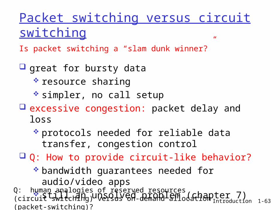
Packet switching versus circuit switching
great for bursty data resource sharing simpler, no call setup
excessive congestion: packet delay and loss protocols needed for reliable data transfer,
congestion control Q: How to provide circuit-like behavior?
bandwidth guarantees needed for audio/video apps
still an unsolved problem (chapter 7)
Is packet switching a “slam dunk winner?”
Q: human analogies of reserved resources (circuit switching) versus on-demand allocation (packet-switching)?

Introduction 1-64
Internet structure: network of networks
roughly hierarchical-- http://navigators.com/internet_architecture.html
at center: “tier-1” ISPs (e.g., Verizon, Sprint, AT&T, Cable and Wireless), national/international coverage treat each other as equals
Tier 1 ISP
Tier 1 ISP
Tier 1 ISP
Tier-1 providers interconnect (peer) privately
NAP
Tier-1 providers also interconnect at public Network Access Points (NAPs)

Introduction 1-65
Tier-1 ISP: e.g., Sprint
Sprint US backbone network
Seattle
Atlanta
Chicago
Roachdale
Stockton
San Jose
Anaheim
Fort Worth
Orlando
Kansas City
CheyenneNew York
PennsaukenRelay
Wash. DC
Tacoma
DS3 (45 Mbps)OC3 (155 Mbps)OC12 (622 Mbps)OC48 (2.4 Gbps)
…
to/from customers
peering
to/from backbone
….
………POP: point-of-presence

Introduction 1-66
Internet structure: network of networks
“Tier-2” ISPs: smaller (often regional) ISPs Connect to one or more tier-1 ISPs, possibly other tier-2 ISPs
Tier 1 ISP
Tier 1 ISP
Tier 1 ISP
NAP
Tier-2 ISPTier-2 ISP
Tier-2 ISP Tier-2 ISP
Tier-2 ISP
Tier-2 ISP pays tier-1 ISP for connectivity to rest of Internet tier-2 ISP is customer oftier-1 provider
Tier-2 ISPs also peer privately with each other, interconnect at NAP

Introduction 1-67
Internet structure: network of networks
“Tier-3” ISPs and local ISPs last hop (“access”) network (closest to end systems)
Tier 1 ISP
Tier 1 ISP
Tier 1 ISP
NAP
Tier-2 ISPTier-2 ISP
Tier-2 ISP Tier-2 ISP
Tier-2 ISP
localISPlocal
ISPlocalISP
localISP
localISP Tier 3
ISP
localISP
localISP
localISP
Local and tier- 3 ISPs are customers ofhigher tier ISPsconnecting them to rest of Internet

Introduction 1-68
Internet structure: network of networks
Introduction 1-69
Internet Tiers
Tier 1 - A network that can reach every other network on the Internet without purchasing IP transit or paying settlements
Tier 2 - A network that peers with some networks, but still purchases IP transit or pays settlements to reach at least some portion of the Internet.
Tier 3 - A network that solely purchases transit from other networks to reach the Internet.
Introduction 1-70
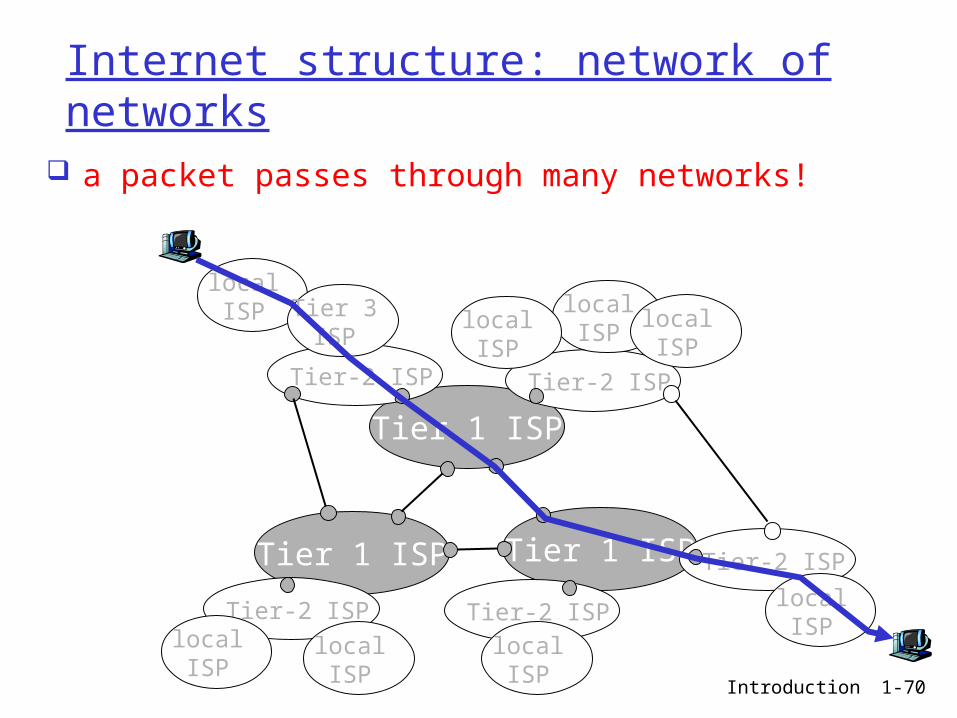
Internet structure: network of networks
a packet passes through many networks!
Tier 1 ISP
Tier 1 ISP
Tier 1 ISP
Tier-2 ISPTier-2 ISP
Tier-2 ISP Tier-2 ISP
Tier-2 ISP
localISPlocal
ISPlocalISP
localISP
localISP Tier 3
ISP
localISP
localISP
localISP
Introduction 1-71
Chapter 1: roadmap
1.1 What is the Internet?1.2 Network edge
end systems, access networks, links
1.3 Network core circuit switching, packet switching, network
structure
1.4 Delay, loss and throughput in packet-switched networks
1.5 Protocol layers, service models1.6 Networks under attack: security1.7 History
Introduction 1-72
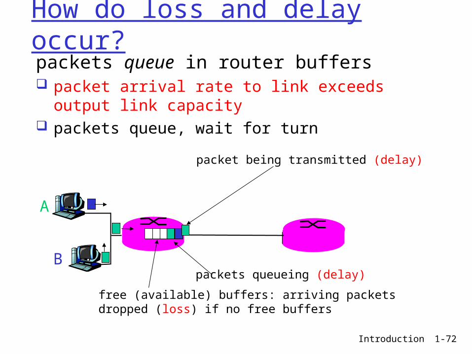
How do loss and delay occur?packets queue in router buffers packet arrival rate to link exceeds output link
capacity packets queue, wait for turn
A
B
packet being transmitted (delay)
packets queueing (delay)
free (available) buffers: arriving packets dropped (loss) if no free buffers
Introduction 1-73
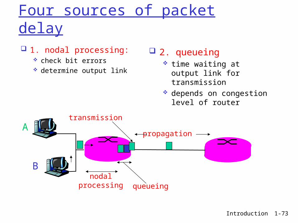
Four sources of packet delay
1. nodal processing: check bit errors determine output link
A
B
propagation
transmission
nodalprocessing queueing
2. queueing time waiting at output
link for transmission depends on congestion
level of router

Introduction 1-74
Delay in packet-switched networks3. Transmission delay: R=link bandwidth
(bps) L=packet length (bits) time to send bits into
link = L/R
4. Propagation delay: d = length of physical
link s = propagation speed in
medium (~2x10⁸ m/sec) propagation delay = d/s
A
B
propagation
transmission
nodalprocessing queueing
Note: s and R are very different quantities!
Introduction 1-75
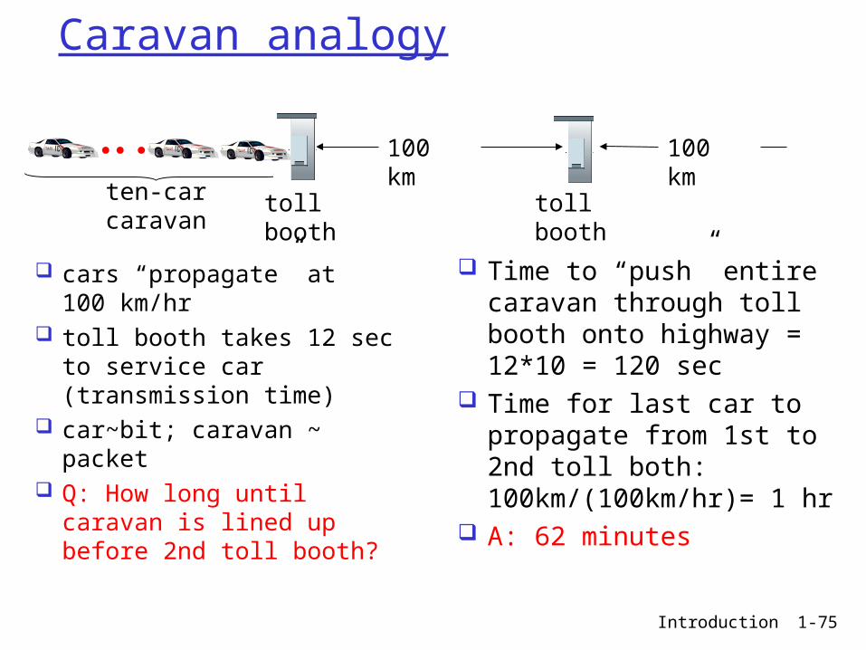
Caravan analogy
cars “propagate” at 100 km/hr
toll booth takes 12 sec to service car (transmission time)
car~bit; caravan ~ packet Q: How long until caravan
is lined up before 2nd toll booth?
Time to “push” entire caravan through toll booth onto highway = 12*10 = 120 sec
Time for last car to propagate from 1st to 2nd toll both: 100km/(100km/hr)= 1 hr
A: 62 minutes
toll booth
toll booth
ten-car caravan
100 km
100 km
Introduction 1-76
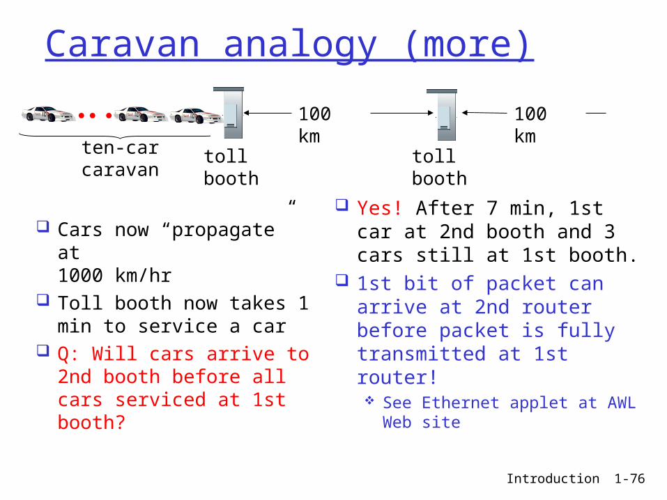
Caravan analogy (more)
Cars now “propagate” at 1000 km/hr
Toll booth now takes 1 min to service a car
Q: Will cars arrive to 2nd booth before all cars serviced at 1st booth?
Yes! After 7 min, 1st car at 2nd booth and 3 cars still at 1st booth.
1st bit of packet can arrive at 2nd router before packet is fully transmitted at 1st router! See Ethernet applet at AWL
Web site
toll booth
toll booth
ten-car caravan
100 km
100 km

Introduction 1-77
Nodal delay
dproc = processing delay typically a few microsecs or less
dqueue = queuing delay depends on congestion
dtrans = transmission delay = L/R, significant for low-speed links
dprop = propagation delay a few microsecs to hundreds of msecs
proptransqueueprocnodal ddddd
Introduction 1-78
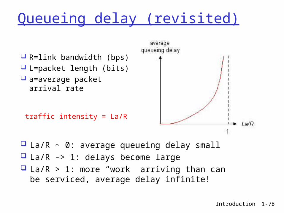
Queueing delay (revisited)
R=link bandwidth (bps) L=packet length (bits) a=average packet
arrival rate
traffic intensity = La/R
La/R ~ 0: average queueing delay small La/R -> 1: delays become large La/R > 1: more “work” arriving than can
be serviced, average delay infinite!
Introduction 1-79
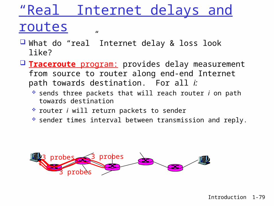
“Real” Internet delays and routes What do “real” Internet delay & loss look like? Traceroute program: provides delay
measurement from source to router along end-end Internet path towards destination. For all i: sends three packets that will reach router i on path
towards destination router i will return packets to sender sender times interval between transmission and reply.
3 probes
3 probes
3 probes
Introduction 1-80
“Real” Internet delays and routes
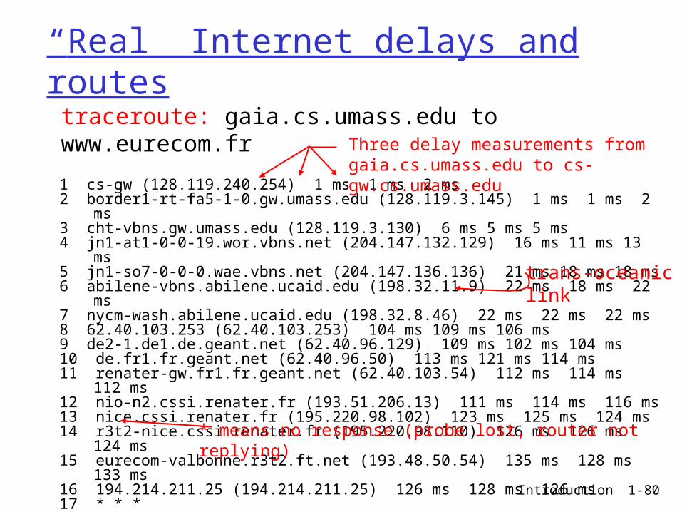
1 cs-gw (128.119.240.254) 1 ms 1 ms 2 ms2 border1-rt-fa5-1-0.gw.umass.edu (128.119.3.145) 1 ms 1 ms 2 ms3 cht-vbns.gw.umass.edu (128.119.3.130) 6 ms 5 ms 5 ms4 jn1-at1-0-0-19.wor.vbns.net (204.147.132.129) 16 ms 11 ms 13 ms 5 jn1-so7-0-0-0.wae.vbns.net (204.147.136.136) 21 ms 18 ms 18 ms 6 abilene-vbns.abilene.ucaid.edu (198.32.11.9) 22 ms 18 ms 22 ms7 nycm-wash.abilene.ucaid.edu (198.32.8.46) 22 ms 22 ms 22 ms8 62.40.103.253 (62.40.103.253) 104 ms 109 ms 106 ms9 de2-1.de1.de.geant.net (62.40.96.129) 109 ms 102 ms 104 ms10 de.fr1.fr.geant.net (62.40.96.50) 113 ms 121 ms 114 ms11 renater-gw.fr1.fr.geant.net (62.40.103.54) 112 ms 114 ms 112 ms12 nio-n2.cssi.renater.fr (193.51.206.13) 111 ms 114 ms 116 ms13 nice.cssi.renater.fr (195.220.98.102) 123 ms 125 ms 124 ms14 r3t2-nice.cssi.renater.fr (195.220.98.110) 126 ms 126 ms 124 ms15 eurecom-valbonne.r3t2.ft.net (193.48.50.54) 135 ms 128 ms 133 ms16 194.214.211.25 (194.214.211.25) 126 ms 128 ms 126 ms17 * * *18 * * *19 fantasia.eurecom.fr (193.55.113.142) 132 ms 128 ms 136 ms
traceroute: gaia.cs.umass.edu to www.eurecom.frThree delay measurements from gaia.cs.umass.edu to cs-gw.cs.umass.edu
* means no response (probe lost, router not replying)
trans-oceaniclink
Introduction 1-81
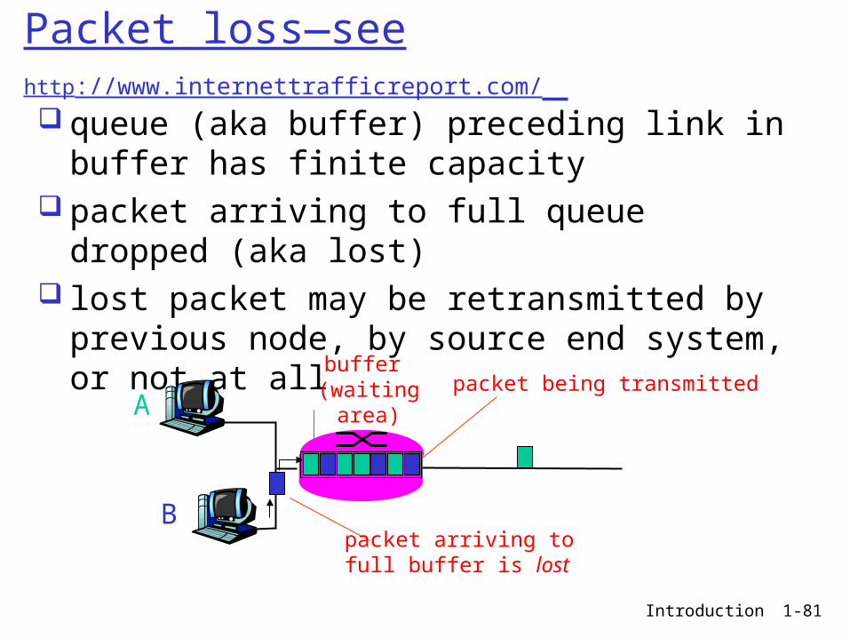
Packet loss—see http://www.internettrafficreport.com/ queue (aka buffer) preceding link in buffer
has finite capacity packet arriving to full queue dropped (aka
lost) lost packet may be retransmitted by
previous node, by source end system, or not at all
A
B
packet being transmitted
packet arriving tofull buffer is lost
buffer (waiting area)
Introduction 1-82
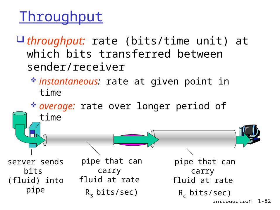
Throughput
throughput: rate (bits/time unit) at which bits transferred between sender/receiver instantaneous: rate at given point in time average: rate over longer period of time
server, withfile of F bits
to send to client
link capacity
Rs bits/sec
link capacity
Rc bits/sec pipe that can carry
fluid at rate
Rs bits/sec)
pipe that can carryfluid at rate
Rc bits/sec)
server sends bits
(fluid) into pipe

Introduction 1-83
Throughput (more)
Rs < Rc What is average end-end throughput?
Rs bits/sec Rc bits/sec
Rs > Rc What is average end-end throughput?
Rs bits/sec Rc bits/sec
link on end-end path that constrains end-end throughput
bottleneck link
Introduction 1-84
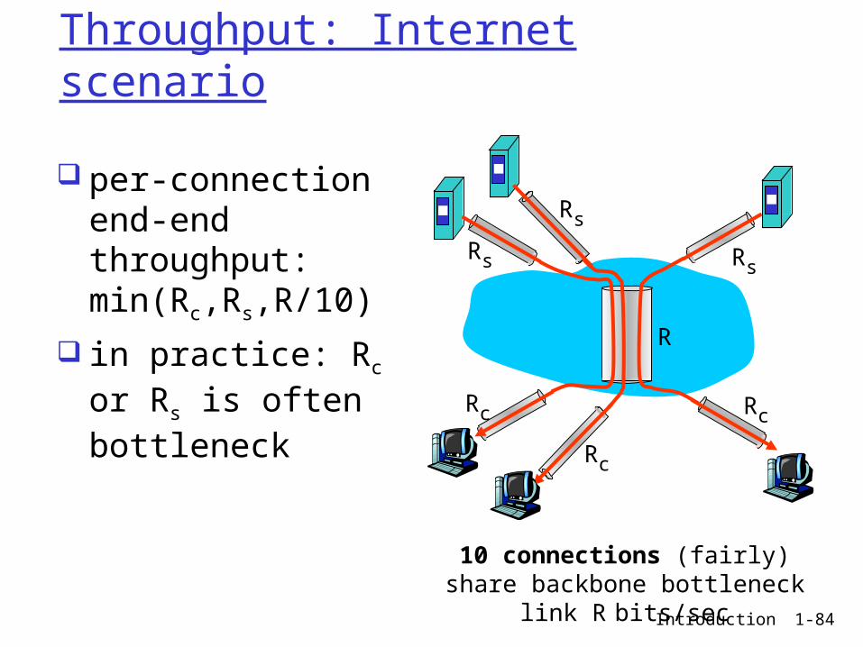
Throughput: Internet scenario
10 connections (fairly) share backbone bottleneck link R
bits/sec
Rs
Rs
Rs
Rc
Rc
Rc
R
per-connection end-end throughput: min(Rc,Rs,R/10)
in practice: Rc or Rs is often bottleneck
Introduction 1-85
Chapter 1: roadmap
1.1 What is the Internet?1.2 Network edge
end systems, access networks, links
1.3 Network core circuit switching, packet switching, network
structure
1.4 Delay, loss and throughput in packet-switched networks
1.5 Protocol layers, service models1.6 Networks under attack: security1.7 History
Introduction 1-86
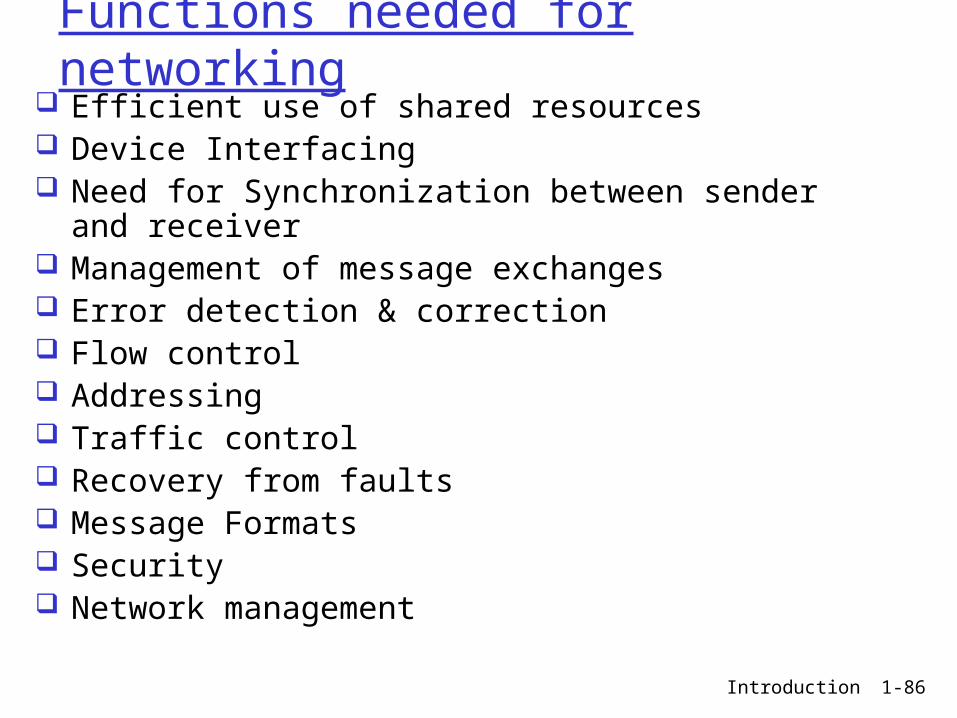
Functions needed for networking Efficient use of shared resources Device Interfacing Need for Synchronization between sender and
receiver Management of message exchanges Error detection & correction Flow control Addressing Traffic control Recovery from faults Message Formats Security Network management
Introduction 1-87
Layered Protocols
Networks need complex functions as listed in the previous slide!
Involves many “pieces” consisted of hardware and software: hosts routers links of various media applications Protocols
To achieve the complex functions, we need a structured approach Layered protocols
Introduction 1-88
Protocol Architecture Complex functions are divided into layers
so that each layer is simpler Each layer achieves certain pre-defined
functions that are provided as services to an upper layer
An upper layer uses the services of a lower layer
A layer is a “service provider”(to it’s upper layer) and a “service user”(from it’s lower layer)
How many layers? A design issue

Introduction 1-89
ISO’s OSI Model(7 layers) ISO 7498: Open Systems Interconnection Model defines 7
layers in 1984
Diagram from http://www2.themanualpage.org
Introduction 1-90
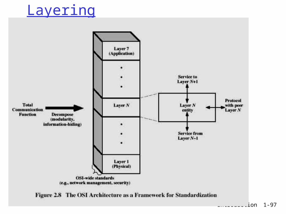
Why layering?
Dealing with complex systems: explicit structure allows identification,
relationship of complex system’s pieces layered reference model for discussion
modularization eases maintenance, updating of system change of implementation of layer’s service
transparent to rest of system e.g., change in gate procedure doesn’t
affect rest of system layering considered harmful?
In some cases, for example, OSI model is criticized having too many layers

Introduction 1-91
Internet protocol stack(TCP/IP)
application: supporting network applications FTP, SMTP, HTTP
transport: host-host data transfer TCP, UDP
network: routing of datagrams from source to destination IP, routing protocols
link: data transfer between neighboring network elements PPP, Ethernet, FDDI, ATM, Frame Relay
physical: bits “on the wire”
application
transport
network
link
physical
Introduction 1-92
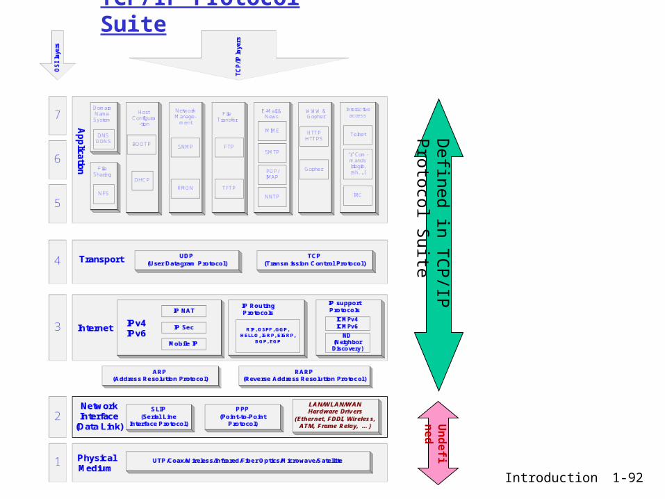
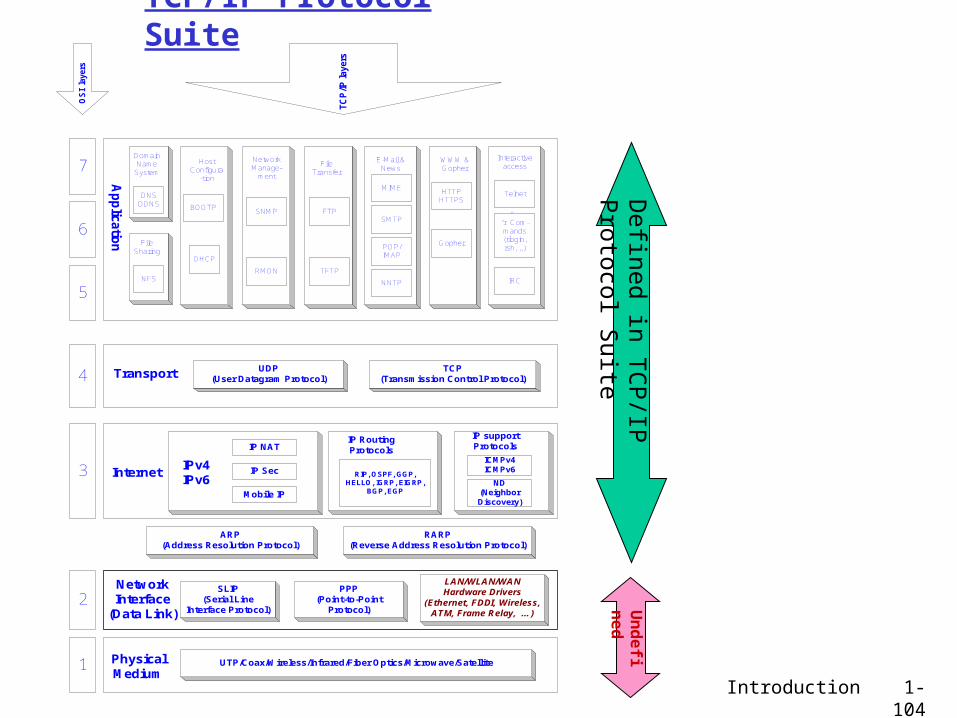
TCP/IP Protocol Suite
Defined in T
CP/IP Protocol S
uiteU
nd
efine
d
Introduction 1-93
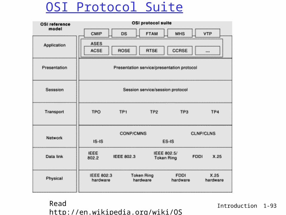
OSI Protocol Suite
Read http://en.wikipedia.org/wiki/OSI_model

Introduction 1-94
Protocol Suites(stacks)

Introduction 1-95
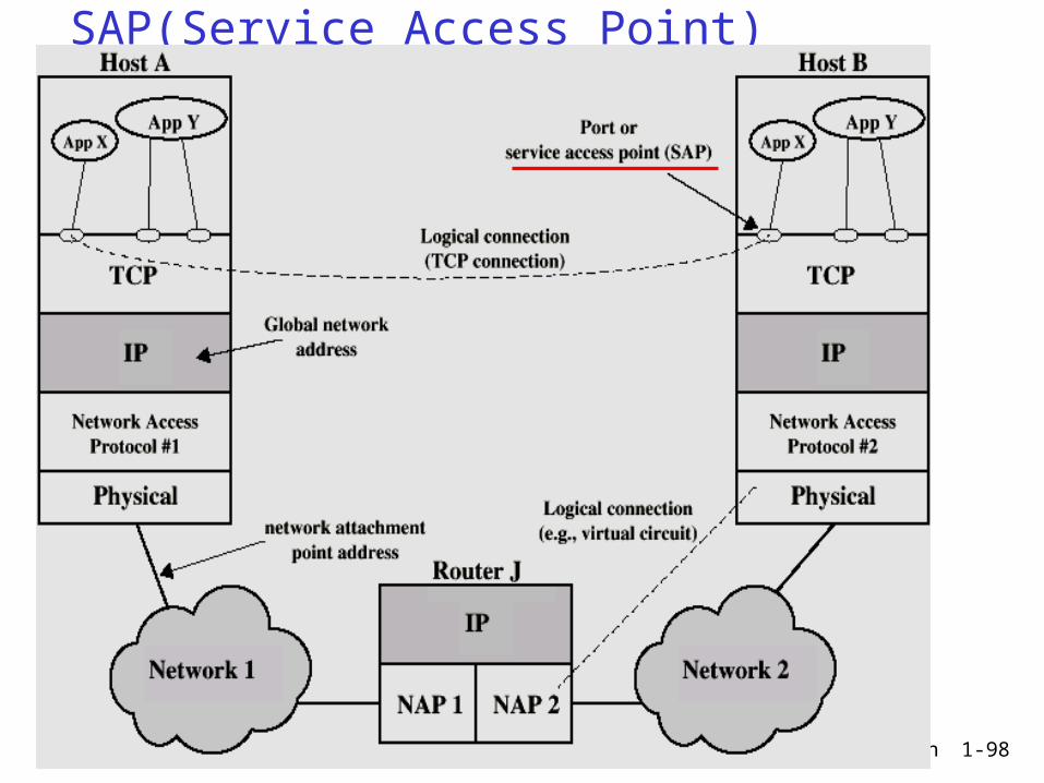
Concepts for layered protocols Services provided by each layer Services are accessed through interface
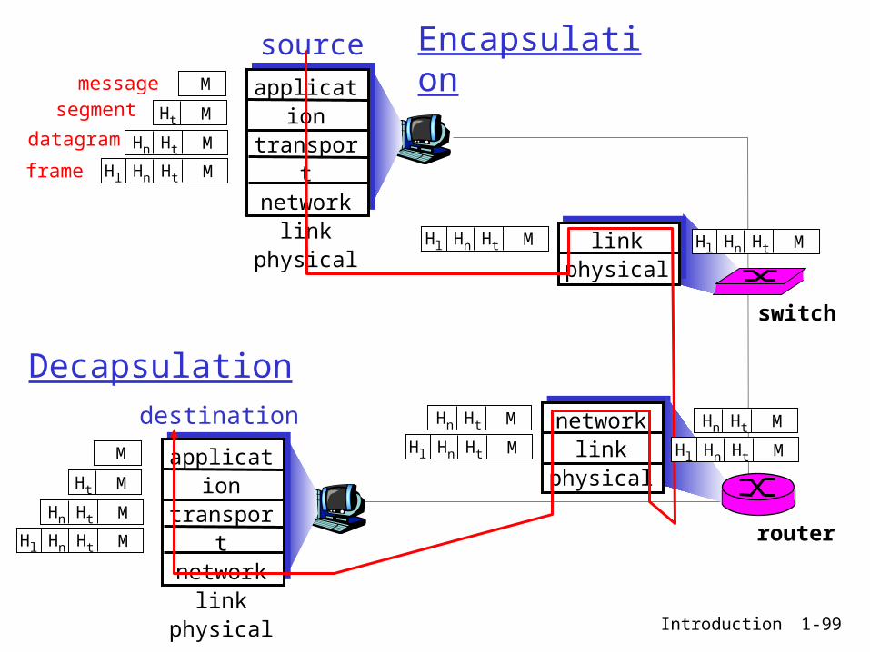
points called SAP(Service Access Points) Data Encapsulation/Decapsulation Virtual communcation between peer layers

Introduction 1-96
Peer –to-peer Virtual Communication
Introduction 1-97
Layering
Introduction 1-98
SAP(Service Access Point)
Introduction 1-99
messagesegment
datagram
frame
sourceapplicatio
ntransportnetwork
linkphysical
HtHnHl M
HtHn M
Ht M
M
destination
application
transportnetwork
linkphysical
HtHnHl M
HtHn M
Ht M
M
networklink
physical
linkphysical
HtHnHl M
HtHn M
HtHnHl M
HtHn M
HtHnHl M HtHnHl M
router
switch
Encapsulation
Decapsulation

Introduction 1-100
Encapsulation/Decapsulation(another view)

Introduction 1-101
Encapsulation in TCP/IP
Introduction 1-102
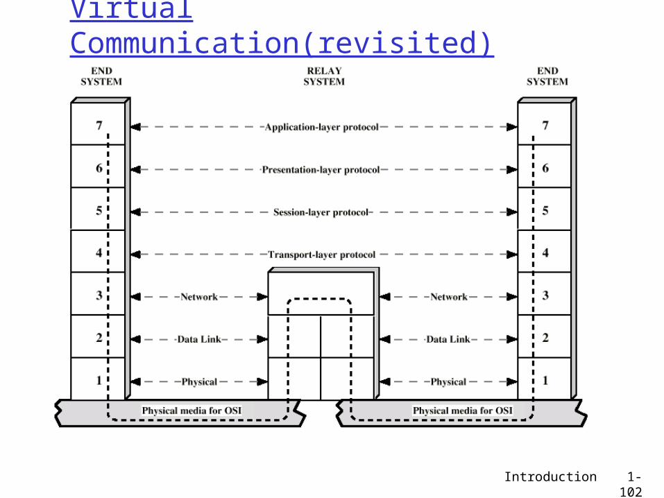
Virtual Communication(revisited)

Introduction 1-103
Nth layer protocol
In a layered protocol, a layer communicates with it’s peer layer using the services of lower layers
This communication should follow strict rules
Nth layer protocol = Strict rules that govern the communication between peer layers
Example: IP, TCP or any existing protocols
Introduction 1-104
TCP/IP Protocol Suite
Defined in T
CP/IP Protocol S
uiteU
nd
efine
d
7
6
5
4
3
2
1
O
SI
laye
rs
T
CP
/IP la
yers
Ap
plicatio
n
DomainName
System
DNSDDNS
FileSharing
NFS
BOOTP
DHCP
HostConfigura
-tion
NetworkManage-
ment
RMON
SNMP
FileTransfer
FTP
TFTP
E-Mail &News
MIME
SMTP
POP/IMAP
NNTP
WWW &Gopher
Interactiveaccess
HTTPHTTPS
Telnet
“r” Com-mands(rlogin,rsh, ,,)
Gopher
IRC
Transport TCP(Transmission Control Protocol)
UDP(User Datagram Protocol)
RARP(Reverse Address Resolution Protocol)
ARP(Address Resolution Protocol)
InternetIPv4IPv6
IP NAT
IP Sec
Mobile IP
IP RoutingProtocols
ICMPv4ICMPv6
ND(NeighborDiscovery)
IP supportProtocols
RIP, OSPF, GGP,HELLO, IGRP, EIGRP,
BGP, EGP
NetworkInterface
(Data Link)
SLIP(Serial Line
Interface Protocol)
PPP(Point-to-Point
Protocol)
LAN/WLAN/WANHardware Drivers
(Ethernet, FDDI, Wireless,ATM, Frame Relay, …)
PhysicalMedium
UTP/Coax/Wireless/Infrared/Fiber Optics/Microwave/Satellite

Introduction 1-105
Chapter 1: roadmap
1.1 What is the Internet?1.2 Network edge
end systems, access networks, links
1.3 Network core circuit switching, packet switching, network
structure
1.4 Delay, loss and throughput in packet-switched networks
1.5 Protocol layers, service models1.6 Networks under attack: security1.7 History

Introduction 1-106
Network Security
The field of network security is about: how bad guys can attack computer networks how we can defend networks against attacks how to design architectures that are immune
to attacks Internet not originally designed with
(much) security in mind original vision: “a group of mutually trusting
users attached to a transparent network” Internet protocol designers playing “catch-
up” Security considerations in all layers!
Introduction 1-107
Bad guys can put malware into hosts via Internet
Malware can get in host from a virus, worm, or trojan horse.
Spyware malware can record keystrokes, web sites visited, upload info to collection site.
Infected host can be enrolled in a botnet, used for spam and DDoS attacks.
Malware is often self-replicating: from an infected host, seeks entry into other hosts

Introduction 1-108
Bad guys can put malware into hosts via Internet
Trojan horse Hidden part of some
otherwise useful software
Today often on a Web page (Active-X, plugin)
Virus infection by receiving
object (e.g., e-mail attachment), actively executing
self-replicating: propagate itself to other hosts, users
Worm: infection by passively
receiving object that gets itself executed
self- replicating: propagates to other hosts, usersSapphire Worm: aggregate scans/sec
in first 5 minutes of outbreak (CAIDA, UWisc data)
Introduction 1-109
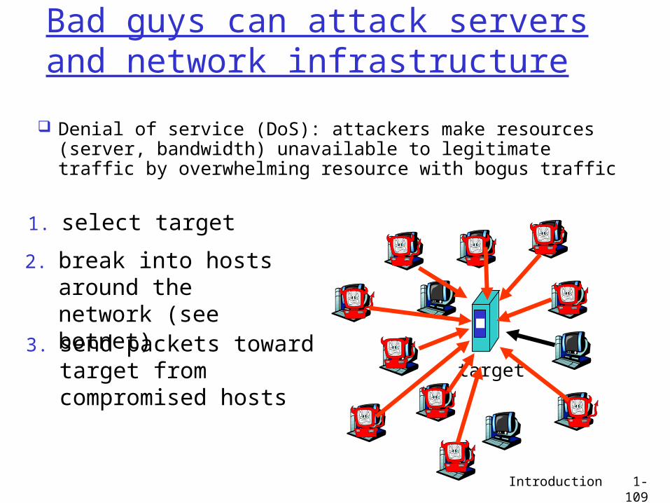
Bad guys can attack servers and network infrastructure
Denial of service (DoS): attackers make resources (server, bandwidth) unavailable to legitimate traffic by overwhelming resource with bogus traffic
1. select target
2. break into hosts around the network (see botnet)
3. send packets toward target from compromised hosts
target

Introduction 1-110
Denial of Service
Distributed Distributed with Reflectors

Introduction 1-111
The bad guys can sniff packetsPacket sniffing:
broadcast media (shared Ethernet, wireless) promiscuous network interface reads/records all packets
(e.g., including passwords!) passing by
Wireshark software used for end-of-chapter labs is a (free) packet-sniffer
A
B
C
src:B dest:A payload
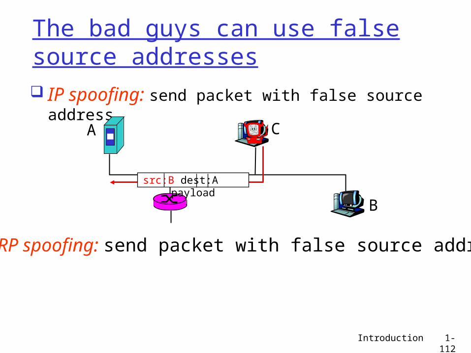
Introduction 1-112
The bad guys can use false source addresses IP spoofing: send packet with false source
addressA
B
C
src:B dest:A payload
ARP spoofing: send packet with false source address

Introduction 1-113
The bad guys can record and playback record-and-playback: sniff sensitive info (e.g.,
password), and use later password holder is that user from system point of
view
A
B
C
src:B dest:A user: B; password: foo

Introduction 1-114
Network Security
more throughout this course chapter 8: focus on security crypographic techniques: obvious uses
and not so obvious uses
Introduction 1-115
Chapter 1: roadmap
1.1 What is the Internet?1.2 Network edge
end systems, access networks, links
1.3 Network core circuit switching, packet switching, network
structure
1.4 Delay, loss and throughput in packet-switched networks
1.5 Protocol layers, service models1.6 Networks under attack: security1.7 History

Introduction 1-116
Internet History
1961: Kleinrock - queueing theory shows effectiveness of packet-switching
1964: Baran - packet-switching in military nets
1967: ARPAnet conceived by Advanced Research Projects Agency
1969: first ARPAnet node operational
1972: ARPAnet public
demonstration NCP (Network Control
Protocol) first host-host protocol
first e-mail program ARPAnet has 15 nodes
1961-1972: Early packet-switching principles

Introduction 1-117
Internet History
1970: ALOHAnet satellite network in Hawaii
1974: Cerf and Kahn - architecture for interconnecting networks
1976: Ethernet at Xerox PARC
ate70’s: proprietary architectures: DECnet, SNA, XNA
late 70’s: switching fixed length packets (ATM precursor)
1979: ARPAnet has 200 nodes
Cerf and Kahn’s internetworking principles: minimalism, autonomy -
no internal changes required to interconnect networks
best effort service model stateless routers decentralized control
define today’s Internet architecture
1972-1980: Internetworking, new and proprietary nets
Introduction 1-118
Internet History
1983: deployment of TCP/IP
1982: smtp e-mail protocol defined
1983: DNS defined for name-to-IP-address translation
1985: ftp protocol defined
1988: TCP congestion control
new national networks: Csnet, BITnet, NSFnet, Minitel
100,000 hosts connected to confederation of networks
1980-1990: new protocols, a proliferation of networks
Introduction 1-119
Internet History
Early 1990’s: ARPAnet decommissioned
1991: NSF lifts restrictions on commercial use of NSFnet (decommissioned, 1995)
early 1990s: Web hypertext [Bush 1945,
Nelson 1960’s] HTML, HTTP: Berners-Lee 1994: Mosaic, later
Netscape late 1990’s:
commercialization of the Web
Late 1990’s – 2000’s: more killer apps: instant
messaging, P2P file sharing
network security to forefront
est. 50 million host, 100 million+ users
backbone links running at Gbps
1990, 2000’s: commercialization, the Web, new apps
Introduction 1-120
Internet History
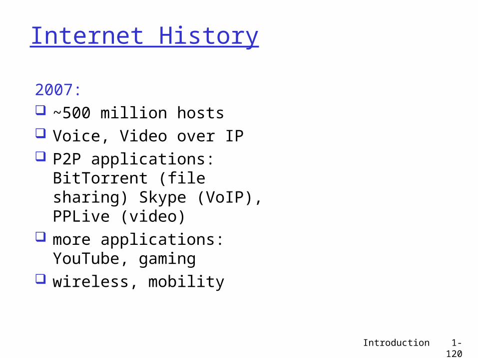
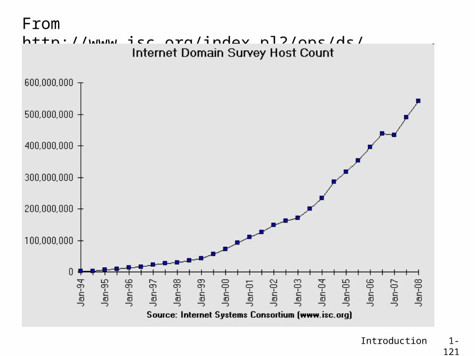
2007: ~500 million hosts Voice, Video over IP P2P applications: BitTorrent
(file sharing) Skype (VoIP), PPLive (video)
more applications: YouTube, gaming
wireless, mobility
Introduction 1-121
From http://www.isc.org/index.pl?/ops/ds/

Introduction 1-122From http://research.lumeta.com/ches/map/gallery/index.html

Introduction 1-123
Internet History: http://www.isoc.org/internet/history/brief.shtml

Introduction 1-124
Introduction: SummaryCovered a “ton” of material! Internet overview what’s a protocol? network edge, core,
access network packet-switching
versus circuit-switching Internet structure
performance: loss, delay, throughput
layering, service models security history
You now have: context, overview,
“feel” of networking more depth, detail
to follow!
Introduction 1-125
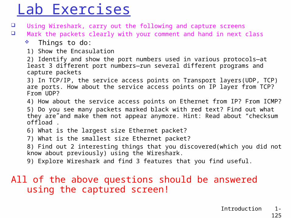
Lab Exercises Using Wireshark, carry out the following and capture screens Mark the packets clearly with your comment and hand in next class
Things to do:1) Show the Encasulation2) Identify and show the port numbers used in various protocols—at least 3 different port numbers—run several different programs and capture packets3) In TCP/IP, the service access points on Transport layers(UDP, TCP) are ports. How about the service access points on IP layer from TCP? From UDP?4) How about the service access points on Ethernet from IP? From ICMP?5) Do you see many packets marked black with red text? Find out what they are and make them not appear anymore. Hint: Read about “checksum offload”.6) What is the largest size Ethernet packet?7) What is the smallest size Ethernet packet?8) Find out 2 interesting things that you discovered(which you did not know about previously) using the Wireshark.9) Explore Wireshark and find 3 features that you find useful.
All of the above questions should be answered using the captured screen!