Embed Size (px)
Citation preview

The design of an overpass crossing on railway in Mirny, Arkhangelska Oblast, Russia
IRINA SANGIRIEVA
Master of Science Thesis Stockholm, Sweden 2011

ii
iii
The design of an overpass crossing on railway in Mirny, Arkhangelsk Oblast, Russia
Irina Sangirieva 2011 TRITA-BKN. Master Thesis 344, YEAR ISSN 1103-4297 ISRN KTH/BKN/EX-344-SE

iv
© Irina Sangirieva, 2011 Supervisor: Professor Håkan Sundquist Co-supervisor: Chief of bridge department Feduhin Sergej Royal Institute of Technology (KTH) Department of Civil and Architectural Engineering Division of Structural Design and Bridges Stockholm, Sweden, 2011

v

vi
Preface I would like to express my gratitude to those who made this Master Thesis possible. First of all to my supervisor at the Department of Civil and Architectural Engineering (KTH) Håkan Sundquist for the professional guidance all through the project and provision of fruitful and interesting basis for discussion. Special thanks to Sergej Feduhin for help with design methods in bridge construction in Russia and for providing me with great insights and feedback. I am also grateful for the help I have received from Aleksej Verbolov, who pro-vided me with useful and interesting information. Thanks to my family and friends for their love and support.
Stockholm, Nov. 2011
Irina Sangirieva

vii
Abstract Bridge design and construction practice in former USSR, especially Russia, is not much
known to the foreign engineers. Many advanced structural theories and construction practices
have been established. In 1931, Franklin D. Roosevelt said, “There can be little doubt that in
many ways the story of bridge building is the story of civilization. By it, we can readily
measure a progress in each particular country.”
The development of bridge engineering is based on previous experiences and historical
aspects. Certainly, the Russian experience in bridge engineering has its own specifics. Bridge
design proceeds in accordance with local standards and specifications.
This study considers the basic rules and standards in bridge design in the North of Russia, the
work includes the overview of Russian design concepts. The paper shows the design of
typical concrete bridges including all calculations and analyses for future bridge stability and
also drawings for visualisation.
The results of the work are conclusions based on performing the required design calculations,
drawings, preparing a final estimate and preparations for the construction. There are also
some notes concerning the Russian design systems, computer programs for designing and
computing and, finally, comparison of the Russians design standards and the Eurocode.
Keywords: design, bridge, standards and rules, highways, beams, superstructure,
substructure, pier, deck

viii
ix
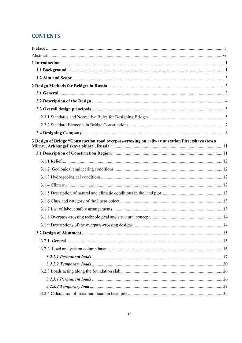
CONTENTS Preface .............................................................................................................................................................. vi Abstract ............................................................................................................................................................ vii 1 Introduction ................................................................................................................................................... 1
1.1 Background ............................................................................................................................................ 1
1.2 Aim and Scope ........................................................................................................................................ 3
2 Design Methods for Bridges in Russia ........................................................................................................ 3 2.1 General .................................................................................................................................................... 3
2.2 Description of the Design ...................................................................................................................... 4
2.3 Overall design principals....................................................................................................................... 5
2.3.1 Standards and Normative Rules for Designing Bridges ................................................................... 5
2.3.2 Standard Elements in Bridge Constructions ..................................................................................... 7
2.4 Designing Company ............................................................................................................................... 8
3 Design of Bridge “Construction road overpass-crossing on railway at station Plesetskaya (town Mirny), Arkhangel’skaya oblast´, Russia” .................................................................................................. 11
3.1 Description of Construction Region ................................................................................................... 11
3.1.1 Relief ............................................................................................................................................... 12
3.1.2 Geological engineering conditions ................................................................................................ 12
3.1.3 Hydrogeological conditions ............................................................................................................ 12
3.1.4 Climate ............................................................................................................................................ 12
3.1.5 Description of natural and climatic conditions in the land plot. ..................................................... 13
3.1.6 Class and category of the linear object. .......................................................................................... 13
3.1.7 List of labour safety arrangements. ................................................................................................. 13
3.1.8 Overpass-crossing technological and structural concept. ............................................................... 14
3.1.9 Descriptions of the overpass-crossing designs................................................................................ 14
3.2 Design of Abutment ............................................................................................................................. 15
3.2.1 General ........................................................................................................................................... 15
3.2.2 Load analysis on column base ....................................................................................................... 16
3.2.2.1 Permanent loads .................................................................................................................... 17 3.2.2.2 Temporary loads .................................................................................................................... 20
3.2.3 Loads acting along the foundation slab .......................................................................................... 26
3.2.3.1 Permanent loads .................................................................................................................... 26 3.2.3.2 Temporary load ...................................................................................................................... 29
3.2.4 Calculation of maximum load on head pile .................................................................................... 35
x
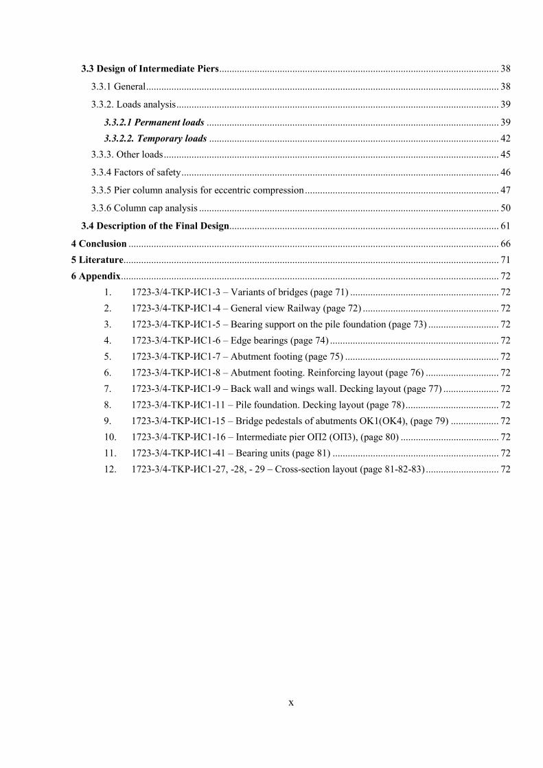
3.3 Design of Intermediate Piers ............................................................................................................... 38
3.3.1 General ............................................................................................................................................ 38
3.3.2. Loads analysis ................................................................................................................................ 39
3.3.2.1 Permanent loads .................................................................................................................... 39 3.3.2.2. Temporary loads ................................................................................................................... 42
3.3.3. Other loads ..................................................................................................................................... 45
3.3.4 Factors of safety .............................................................................................................................. 46
3.3.5 Pier column analysis for eccentric compression ............................................................................. 47
3.3.6 Column cap analysis ....................................................................................................................... 50
3.4 Description of the Final Design ........................................................................................................... 61
4 Conclusion ................................................................................................................................................... 66 5 Literature ..................................................................................................................................................... 71 6 Appendix ...................................................................................................................................................... 72
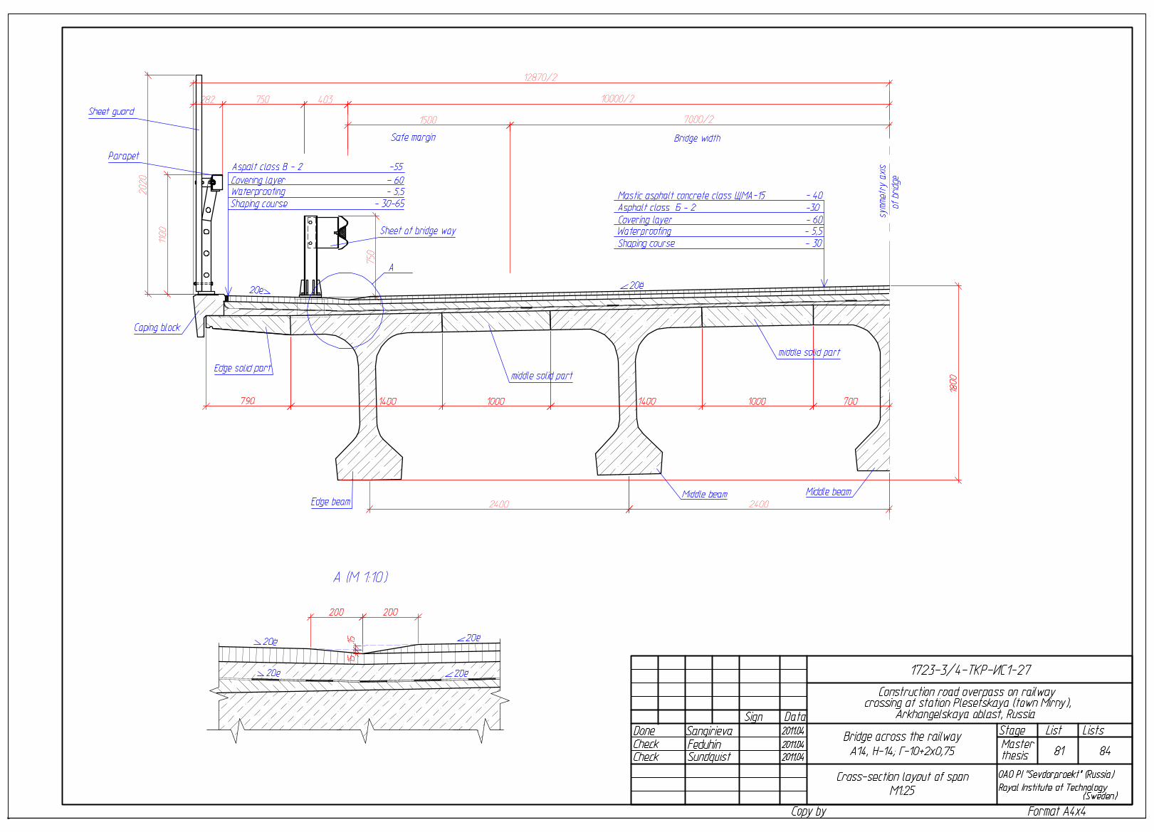
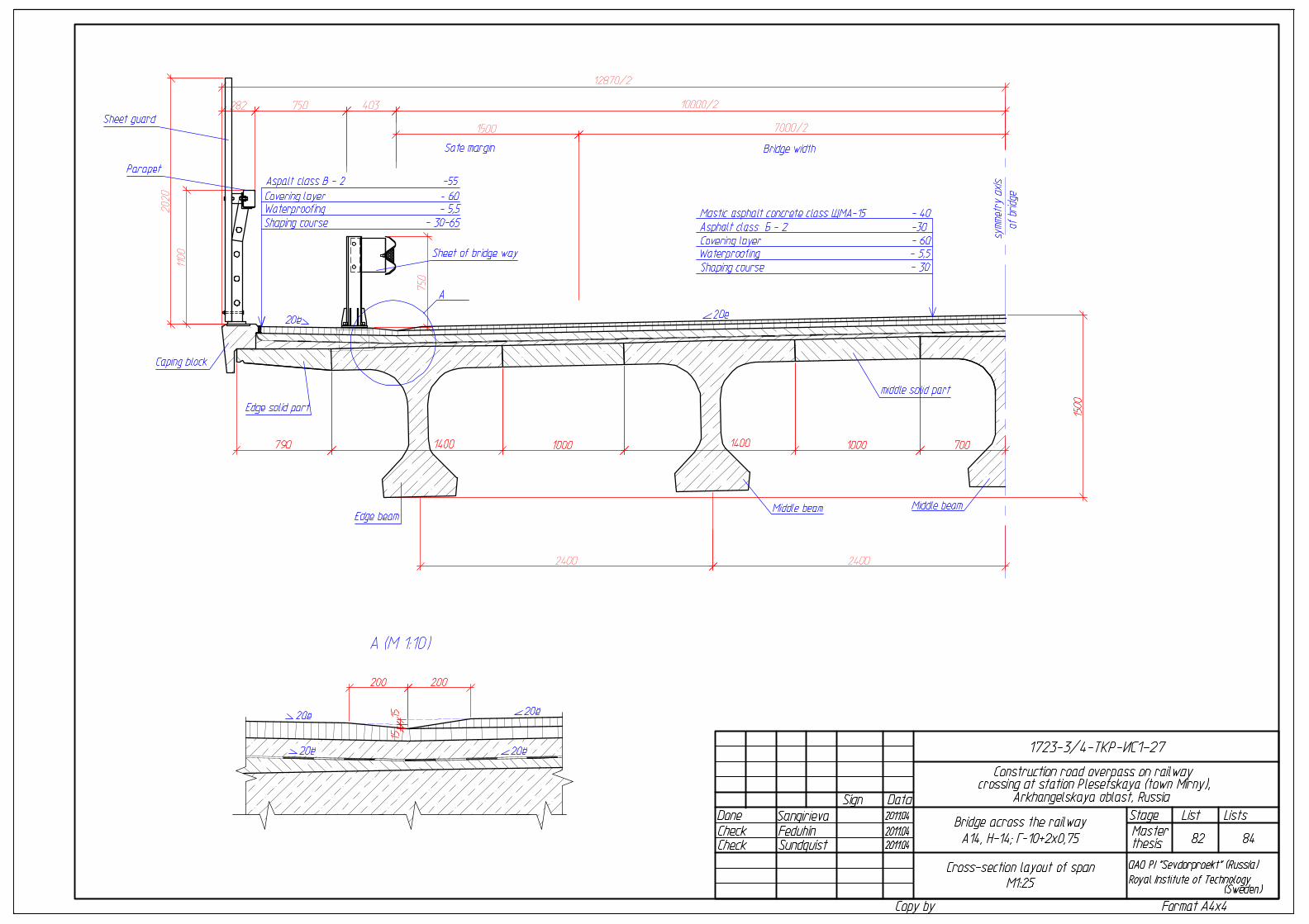
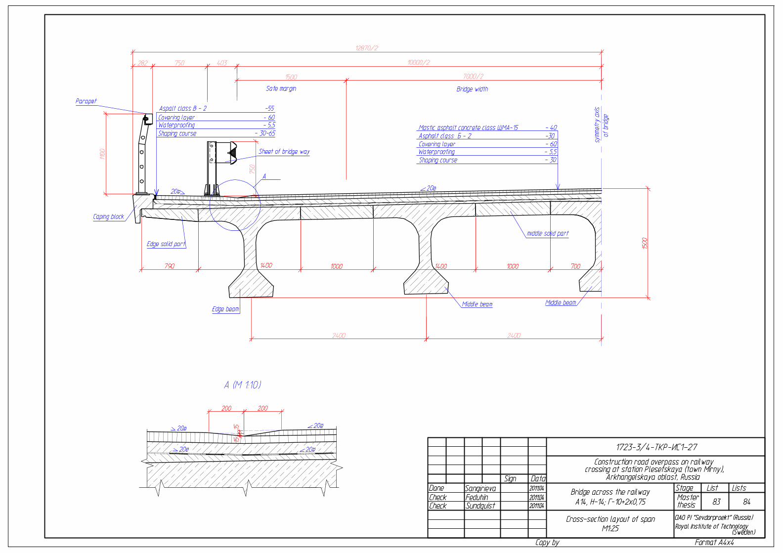
1. 1723-3/4-TKP-ИС1-3 – Variants of bridges (page 71) ........................................................... 72 2. 1723-3/4-TKP-ИС1-4 – General view Railway (page 72) ...................................................... 72 3. 1723-3/4-TKP-ИС1-5 – Bearing support on the pile foundation (page 73) ............................ 72 4. 1723-3/4-TKP-ИС1-6 – Edge bearings (page 74) ................................................................... 72 5. 1723-3/4-TKP-ИС1-7 – Abutment footing (page 75) ............................................................. 72 6. 1723-3/4-TKP-ИС1-8 – Abutment footing. Reinforcing layout (page 76) ............................. 72 7. 1723-3/4-TKP-ИС1-9 – Back wall and wings wall. Decking layout (page 77) ...................... 72 8. 1723-3/4-TKP-ИС1-11 – Pile foundation. Decking layout (page 78) ..................................... 72 9. 1723-3/4-TKP-ИС1-15 – Bridge pedestals of abutments OK1(OK4), (page 79) ................... 72 10. 1723-3/4-TKP-ИС1-16 – Intermediate pier ОП2 (ОП3), (page 80) ....................................... 72 11. 1723-3/4-TKP-ИС1-41 – Bearing units (page 81) .................................................................. 72 12. 1723-3/4-TKP-ИС1-27, -28, - 29 – Cross-section layout (page 81-82-83) ............................. 72
1
1 Introduction
1.1 Background A bridge is a construction built to span physical obstacles such as a body of water, valley, or road,
for the purpose of providing passage over the obstacle. Designs of bridges vary depending on the
function of the bridge, the nature of the terrain where the bridge is constructed, the material used for
construction and the funds available to build it.
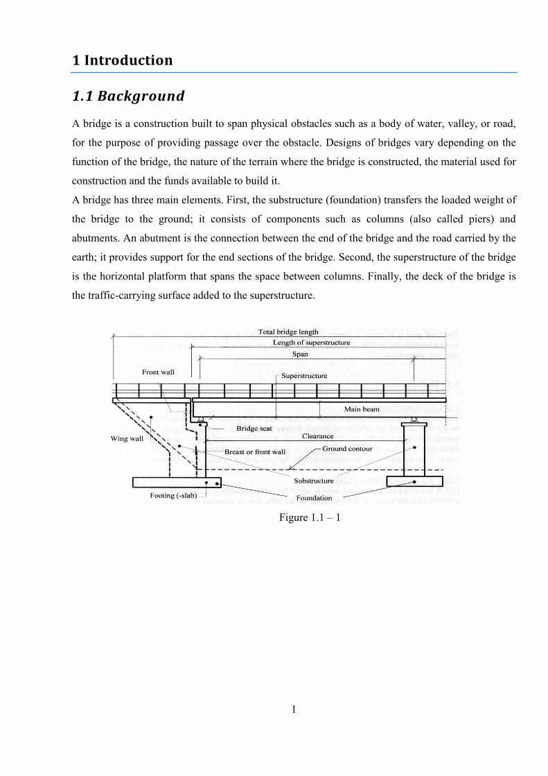
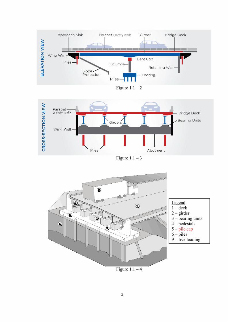
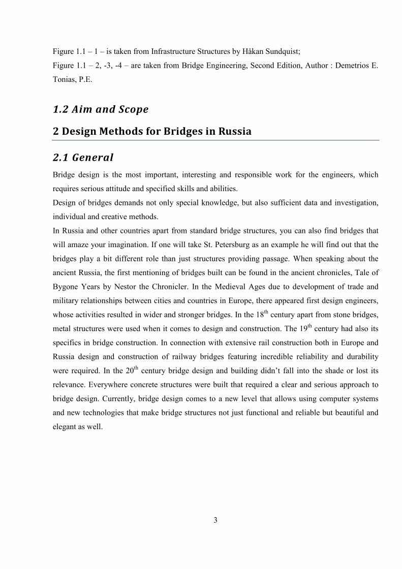
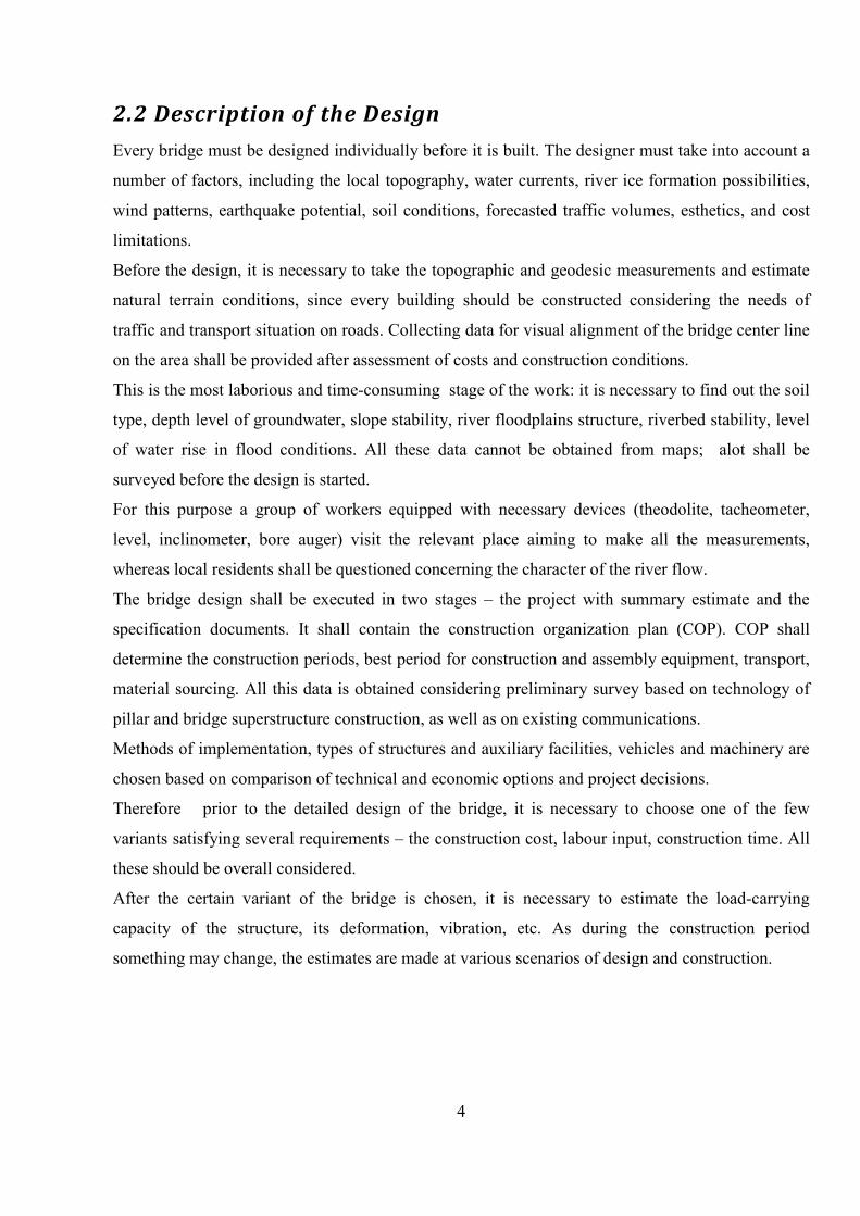
A bridge has three main elements. First, the substructure (foundation) transfers the loaded weight of
the bridge to the ground; it consists of components such as columns (also called piers) and
abutments. An abutment is the connection between the end of the bridge and the road carried by the
earth; it provides support for the end sections of the bridge. Second, the superstructure of the bridge
is the horizontal platform that spans the space between columns. Finally, the deck of the bridge is
the traffic-carrying surface added to the superstructure.
Figure 1.1 – 1
2
Figure 1.1 – 2
Figure 1.1 – 3
Figure 1.1 – 4
Legend: 1 – deck 2 – girder 3 – bearing units 4 – pedestals 5 – pile cap 6 – piles 9 – live loading
3
Figure 1.1 – 1 – is taken from Infrastructure Structures by Håkan Sundquist;
Figure 1.1 – 2, -3, -4 – are taken from Bridge Engineering, Second Edition, Author : Demetrios E.
Tonias, P.E.
1.2 Aim and Scope 2 Design Methods for Bridges in Russia
2.1 General Bridge design is the most important, interesting and responsible work for the engineers, which
requires serious attitude and specified skills and abilities.
Design of bridges demands not only special knowledge, but also sufficient data and investigation,
individual and creative methods.
In Russia and other countries apart from standard bridge structures, you can also find bridges that
will amaze your imagination. If one will take St. Petersburg as an example he will find out that the
bridges play a bit different role than just structures providing passage. When speaking about the
ancient Russia, the first mentioning of bridges built can be found in the ancient chronicles, Tale of
Bygone Years by Nestor the Chronicler. In the Medieval Ages due to development of trade and
military relationships between cities and countries in Europe, there appeared first design engineers,
whose activities resulted in wider and stronger bridges. In the 18th century apart from stone bridges,
metal structures were used when it comes to design and construction. The 19th century had also its
specifics in bridge construction. In connection with extensive rail construction both in Europe and
Russia design and construction of railway bridges featuring incredible reliability and durability
were required. In the 20th century bridge design and building didn’t fall into the shade or lost its
relevance. Everywhere concrete structures were built that required a clear and serious approach to
bridge design. Currently, bridge design comes to a new level that allows using computer systems
and new technologies that make bridge structures not just functional and reliable but beautiful and
elegant as well.
4
2.2 Description of the Design Every bridge must be designed individually before it is built. The designer must take into account a
number of factors, including the local topography, water currents, river ice formation possibilities,
wind patterns, earthquake potential, soil conditions, forecasted traffic volumes, esthetics, and cost
limitations.
Before the design, it is necessary to take the topographic and geodesic measurements and estimate
natural terrain conditions, since every building should be constructed considering the needs of
traffic and transport situation on roads. Collecting data for visual alignment of the bridge center line
on the area shall be provided after assessment of costs and construction conditions.
This is the most laborious and time-consuming stage of the work: it is necessary to find out the soil
type, depth level of groundwater, slope stability, river floodplains structure, riverbed stability, level
of water rise in flood conditions. All these data cannot be obtained from maps; alot shall be
surveyed before the design is started.
For this purpose a group of workers equipped with necessary devices (theodolite, tacheometer,
level, inclinometer, bore auger) visit the relevant place aiming to make all the measurements,
whereas local residents shall be questioned concerning the character of the river flow.
The bridge design shall be executed in two stages – the project with summary estimate and the
specification documents. It shall contain the construction organization plan (COP). COP shall
determine the construction periods, best period for construction and assembly equipment, transport,
material sourcing. All this data is obtained considering preliminary survey based on technology of
pillar and bridge superstructure construction, as well as on existing communications.
Methods of implementation, types of structures and auxiliary facilities, vehicles and machinery are
chosen based on comparison of technical and economic options and project decisions.
Therefore prior to the detailed design of the bridge, it is necessary to choose one of the few
variants satisfying several requirements – the construction cost, labour input, construction time. All
these should be overall considered.
After the certain variant of the bridge is chosen, it is necessary to estimate the load-carrying
capacity of the structure, its deformation, vibration, etc. As during the construction period
something may change, the estimates are made at various scenarios of design and construction.
5
2.3 Overall design principals Design Concepts and Philosophy
In the former Soviet Union, the ultimate strength design method (strength method) was adopted
for design of bridges and culverts in 1962. Three limit states:
1 - the strength at ultimate load,
2 - deformation at service load,
3 - cracks width at service load
— were specified in the bridge design standard, a predecessor of the current bridge code. Later, the
limit states 2 and 3 were combined in one group. The State Standard: GOST 27751-88 “Reliability
of Constructions and Foundations” specifies two limit states: strength and serviceability. The first
limit state is related to the structural failure such as loss of stability of the structure or its parts,
structural collapse of any character (ductile, brittle, fatigue) and development of the mechanism in a
structural system due to material yielding or shear at connections. The second limit is related to the
cracking (crack width), deflections of the structure and foundations, and vibration of the structure.
The main principles for design of bridges are specified in the Building Codes and Regulations -
“Bridges and Pipes” SNIP 2.05.03-84 [1]. The ultimate strength is obtained from specified material
strengths (e.g., the concrete at maximum strength and usually the steel yielding). The analysis of
bridge superstructure is normally implemented using three-dimensional analysis models.
2.3.1 Standards and Normative Rules for Designing Bridges One of the varieties of reinforced concrete bridges are composite bridges. Their reinforced concrete
slab is rigidly fixed to the main steel beams, thus they work integrally reducing steel consumption
by 12-18 %. This construction has excellent functional performance, but costs high, and involves
much labour input and installation difficulties. Steel beams of the composite construction feature
welded I-sections, and their height is 1/13-1/15 from the bay. Vertical walls of the steel plate girders
reach 12-14 mm in width, being secured by bilateral vertical stiffeners to improve stability. Longer
spans (more than 45 m) are equipped with longitudinal ribs in the compressive side of beams.
Beams of more than 45 m are produced as single blocks that are joined together later with high-
strength bolts with the help of vertical and horizontal overlaps. Steel beams of smaller spans are
mostly equipped with connectors at the factory, and that makes their further installation simpler.
6
When design and construct new bridges it is necessary to consider requirements of the national
State Standard Specification Р52748-2007 (effective since 01.01.2008) which defines the intended
load A-14 for bridgeworks of any category.
The design of bridges in Russia is based on the following rules:
Construction Standards and Regulations 2.05.03-84* (design),
Construction Standards and Regulations 3.06.04-91 (implementation),
Construction Standards and Regulations 3.06.07-86 (Rules of tests and surveys).
Design solutions must provide reliability and durability of constructions, their architectural
expression, reduction of construction impacts on the urban environment, prudent use of the city
area, minimum works on the communications redevelopment, convenience and economy of
operation and repair ability, rapid installation with minimal restriction of transport and pedestrians
movement during construction. The reconstruction bridge design should consider the physical
condition and load-carrying capacity of constructions and provide for the improvement of their
technical and operational parameters after reconstruction.
In most cases the bridge construction is based on the list of standard specification documents and
projects for the trial and repeated usage at the construction of roads and accompanying facilities,
developed and published on 01.01.2006. The list contains standard and accepted trial projects to be
used in construction design.
Series 3.503.1-81. Spans precast reinforced concrete constructions 12, 15, 18, 21, 24, 33 m in length
of the I-section beams with pre-stressing steel reinforcement for bridges and overpass-crossings
located on public roads, streets and city roads.
TP of Series 3.503.1-81 - Spans precast 12, 15, 18, 21, 24, 33 m in length of the I-section beams
with pre-stressing steel reinforcement for bridges and overpass-crossings located on public roads.
TP of Series 3.503.1-60 - Columnar highway bridges supports made of reinforced concrete
elements 0.8 m in diameter with plate-free foundation under the spans from 12 to 33 m in length.
TP of Series 3.500.1-1.93 - Knock-reinforced concrete one-piece piles of solid square section for
the bridge supports. (Issue 0, Issue 1, Issue 2)
TP of Series 3.503.1-96 - Coupling of highway bridges and overpass-crossings with embankment.
TP of Series 503-09-7.84 - Construction of bridges on logging roads of the inventory metal spans
18, 24 and 33m in length on wooden poles. Issue 1 Spans. Drawings ML
7
2.3.2 Standard Elements in Bridge Constructions Materials and constructions used for the supporting building should satisfy the following
regulations:
Construction Standards and Regulations 2.05.03-84* par. 3.1-3.6 - main design
requirements for reinforced concrete structures,
State Standard Specification 27751-88* - reliability of building structures and
grounds,
State Standard Specification 26633-91* - main design requirements for concrete;
composition of concrete mix, preparation, acceptance rules.
Control methods should correspond to the State Standard Specification 7473-94, par. 2.6, par. 2.7;
materials for concrete making should comply with the requirements of the State Standard
Specification 30515-97*; cement should be accepted in accordance with the State Standard
Specification 30515-97, transportation and cement storage - according to the State Standard
Specification 30515-97 and Construction Standards and Regulations 3.09.01-85*, par. 2.1 BR
3.03.01-87 and the State Standard Specification 5781-82* - hot-rolled steel for the reinforcement of
concrete bridges, the State Standard Specification 380-2005 – carbon steel of commercial quality,
the State Standard Specification 6713-91 - low alloyed constructional rolling for bridges
construction.
All materials and equipment should be agreed with the Project Manager.
Design schemes and their basic premise should reflect the actual conditions of the bridges and pipes
construction during its operation and building. The bridge spans’ construction, as a rule, should be
designed as spatial and if dismembered into flat systems - by approximate methods developed by
the design practice. Interaction of the elements with each other and with the ground should be
considered, too.
If the Regulations do not set forth the design methods for efforts in structural elements of bridges
and pipes with due consideration of emerging inelastic deformation, it is permitted to determine
these efforts with the assumption of elastic work of the accepted design scheme.
Based on the appropriate justification it is allowed to make the design on the deformed scheme
considering the effect of the structure displacement under load. The choice of design schemes, as
well as methods for designing construction of bridges and pipes should be performed in accordance
with the effective use of computers.
8
Load-bearing structures and foundations of bridges and piers should be designed with consideration
of permanent loads and adverse combination of temporary loads specified in Pt. 2. The design
should be performed by extreme limit states accordingly to the requirements of ST CMEA 384-76
(STANDARD CMEA CONCRETE AND REINFORCED CONCRETE CONSTRUCTIONS).
2.4 Designing Company The highway engineering organization was set up in Arkhangelsk Oblast more than 40 years ago.
Originally it was a construction group, after that it developed into the construction department and
the construction office. In the late 1980s the governmental program “Dorogi Nechernozem’ya”
recovered highway engineering throughout the country. In April of 1991 the construction institution
“Sevdorproekt” was set up as independent state-owned enterprise on the basis of the construction
office. In this period the market of design and survey works formed. “Sevdorproekt” renders the
service on design and survey works of highways of various designation, bridges, separation
structures, transport infrastructure objects.
Currently the staff numbers 66 persons. It consists of 3 surveying groups, the highway engineering
department, the bridge engineering department, the highway objects engineering group, and the
geological department. The company performs works throughout Arkhangelsk Oblast and in the
regions of the Far North
Computer-aided Design
For bridges construction and design the bridge department uses the computer complex (CC)
“LYRA-WINDOWS”. This computer complex enables designers to analyze the stress-deformed
state (SDS) of constructions in linear and non-linear formulation (physical and geometrical) without
limitations under the terms of the tasks dimension.
The opportunity of using the “history” of creating and loading a construction is provided with the
postprocessor “Installation”, which allows for a more precise analysis of the working cycle of
construction and its elements.
The possibility of “MicroStation” software package using for the transport construction design has
changed the approach to the construction of bridgeways. The department masters “MicroStation
TriForma” program that allows the designer to build a three-dimensional bridge model in the virtual
space of the standard elements filed to the database. Therefore, a 3D map of the Earth is formed by

9
the exploration units with the help of modern electronic field tacheometers, to be later processed by
the program “TerraSurvey” and transferred directly to the designer’s computer.
The bridge model can be assembled from individual elements or from large blocks being the
standard sets. For example, an intermediate support with bearings or with cant, the extreme support
of the cant, cabinet wall unit and connecting elements (adapter plates, ledgers etc.). The standard
sets are also the following: span constructions with barrier elements for the roadway, sidewalks and
curb blocks, roadway constructions and movement joints constructions. The database replenishment
is in progress, including the reflection of the support reactions, the construction’s lifetime,
individual joints etc., which enables creating the smart digital model of a bridge. After the model is
transferred to a Customer, it will get a definite life cycle. In the bridge model there is an opportunity
to display defects of construction that arise during the use, results of actual repairs and volume of
the implemented reconstruction etc. Optionally, the 3-D model can be used for generating drawings,
automatic calculation of the excavation works and specifications preparation.
MAV.Structure - structural analysis by finite element method
MAV.Structure program is designed for the numerical investigation of stress-strain state, dynamics
and stability of structures. Its distinguishing feature is a device for calculating the bridge structures,
the ability to build and post-processing lines and influence surfaces, as well as a built-in
programming language, designed to automate complex calculations and support the calculations
made in preparing the initial data, for example, the identification and registration of numerous
factors, dictated by regulations.
To work with the program MAV.Structure must have basic structural mechanics and have computer
skills. It is also desirable, but not necessarily, have a basic knowledge of programming, be able to
make the algorithms (no matter what language), as this will fully take advantage of the complex.
The complex is best suited for the automation of calculations by the normative documents of
research in structural mechanics and to build complex computational algorithms, where the user can
use several interconnected structures of recalculations by the FEM, and can specify complex
algorithms for processing information prior to settlement and after settlement (preprocessors and
postprocessors). For example, you can create an algorithm of forming a design scheme that depends
on several parameters and programmed, for example, an automatic check of the conditions snip.
Then, using established algorithms can be calculated in batch mode, multiple structures that differ
by only a few parameters. For example, you can create a template for determining the carrying
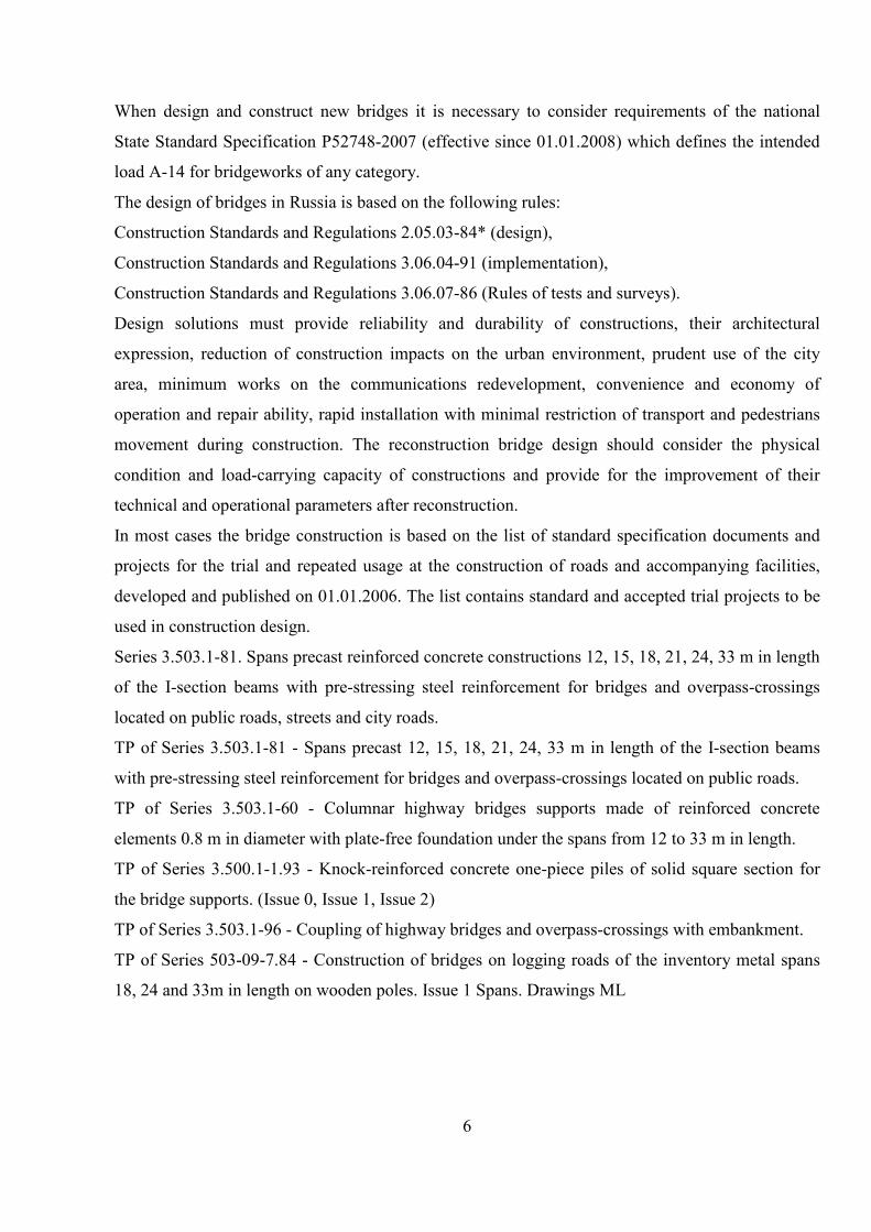
capacity of several overpass-crossings of the same type of beam, and then just ask a few initial
10
parameters for each overpass-crossing (the length of spans, the number of types of beams, the
number of beams in diameter, height, supports, etc.), and the calculation of each overpass-crossing
will be executed is automatically set algorithm. This will save much time. Below figures of
calculations in that program are shown.
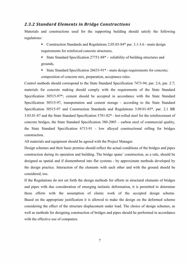
Figure 2.4 – 1
Figure 2.4 – 2
11
3 Design of Bridge “Construction road overpass-crossing on railway at station Plesetskaya (town Mirny), Arkhangel’skaya oblast´, Russia”
3.1 Description of Construction Region Currently the highway Arkhangelsk (starting at Brin-Navolok village) – Kargopol – Vytegra (to
Proshkino station) provides the internal and inter-district connections and also provide links with
the Vologda and the Leningrad regions, republic of Karelia and Finland (Northern transport
corridor).
Further increase of traffic volumes on above directions will result from region’s economic growth,
development of the international and regional connections, and development of new transport
corridors.
Mirny city occupies 5,081 hectares within the city boundaries. The city-planning scheme is
rectangular. The houses are made of brick, wood and are built 1-12 storied. The streets are narrow,
straight, and paved. The total length of streets and block passes is 32.5 km.
Population of the Mirny amounts to 27.847 thousand people as of 1/01/2008.
Plesetsk is an urban village and the administrative center of the Plesetsk District of the Arkhangelsk
Region. In 2008 its population amounted to 10.2 thousand people. Plesetskaya railway station
serves as a junction point for Plesetsk Cosmodrome and the city of regional subjection Mirny,
serving the cosmodrome. Plesetsky district has a road access to the federal roads to Moscow and St.
Petersburg. Mirny and Plesetsk are connected by the regular bus transportation (from 7am till
12am) and taxi. The increasing railway and motor traffic demands that the railroad should cross the
highways at separate grades. The northern railway crossing Plesetsk village km 917+PK 2, the
existing crossing of the railway with the highway at grade results both in traffic jams and road
accidents.
In connection with electrification of the railway and increasing rakes’ length by 1.5–2 times the at-
grade northern crossing often gets closed for vehicles. The growing volumes of railway and road
traffic demands that the railroad should cross the highways at separate grades. The northern railway
crossing Plesetsk village km 917+PK 2, the existing crossing of the railroad with the highway on
one level leads not only to traffic jams but also significantly affects the traffic security.
The major part of the cargos transported by road consists of industrial, trade and procurement trade
cargos. The main significant point of the fluent transit traffic is the fast and safe traffic between
12
satellite towns and undisturbed traffic of transit cars by the public road Arkhangelsk (from Brin-
Navolok village) – Kargopol – Vytegra (to Proshkino station).
Further increase of transport connections is caused by the region’s economic growth, development
of the international and regional connections, and creation of new transport corridors.
3.1.1 Relief The line of the motor overpass-crossing to be designed runs on flat land. On the lay of line, the
natural run-off is provided on the western side (where it crosses the railroad) by water drains of the
railway and “Arkhangelsk (Brin-Navolok village) – Kargopol – Vytegra (Proshkino station)
motorway; on the eastern side (Mirny town) – by the sloping relief stretching down to the Sukhoye
and the Plesetskoye Lakes
3.1.2 Geological engineering conditions Based on engineering-geological studies carried out on the project site, reliable geological field
documentation, lab analysis of disturbed-structure soils, structural-textural genesis and in
accordance with GOST 20522-96 - Soils. Statistical treatment of the test results and GOST 25100-
95 - Soils. Classification, some 13 geo-technical elements (EGE) were installed 20-m deeper than
the surface
3.1.3 Hydrogeological conditions No ground water surveys have been conducted in the area.
3.1.4 Climate According to the road-climate zoning of Russia provided for by the Construction Norms &
Regulations 23-01-99*, the field survey work area is classified as road-climate zone II.
The climate in the area of lay of line is moderately continental, with long cold winters and short
summers with minimum air temperature -50 °С and maximum +35 °С. The coldest months are
January and February, the hottest is July. The period when years-long temperature falls over 0°С is
10.04 – 22.10; over +5°С 30.04 – 29.09; over +10°С 25.05 – 7.09. The number of days with
temperature over 0°С is 194; over +5°С - 151; over +10°С - 104.
13
The snow cover normally forms and melts during 12.11 - 22.04, the period of snow cover lasts 163
days. The decade average depth of snow is 48 cm. The average snow cover depth is 67 cm. Clay
and loamy soils may freeze down to 160 cm, sands and sand loams – down to 195 cm.
3.1.5 Description of natural and climatic conditions in the land plot. No geotechnical processes, either natural or economic activity-induced, have been identified. The
area surveyed does not contain any specific soils. According to Construction Norms & Regulations
2.05.02-85, the area along the lay of line is classified as moisture class II.
Climatic description is based on Construction Norms & Regulations 23-01-99* “Construction
Climatology” and Emtsa Meteorological Station’s climate data sheets published by
Hydrometeorological Service.
3.1.6 Class and category of the linear object. According to the design and estimate documentation development task : “Construction of the motor
overpass-crossing above ‘Plesetskaya-Mirny’ railway section and bypass highway”, the road being
designed is classified as technical category III. According to the Construction Norms & Regulations
2.05.02 – 85*, Construction Norms & Regulations 2.07.01 – 89** in the part of road interchange
points and the industry building code 25-86 relating to different-level road interchange, the
following standards will be observed:
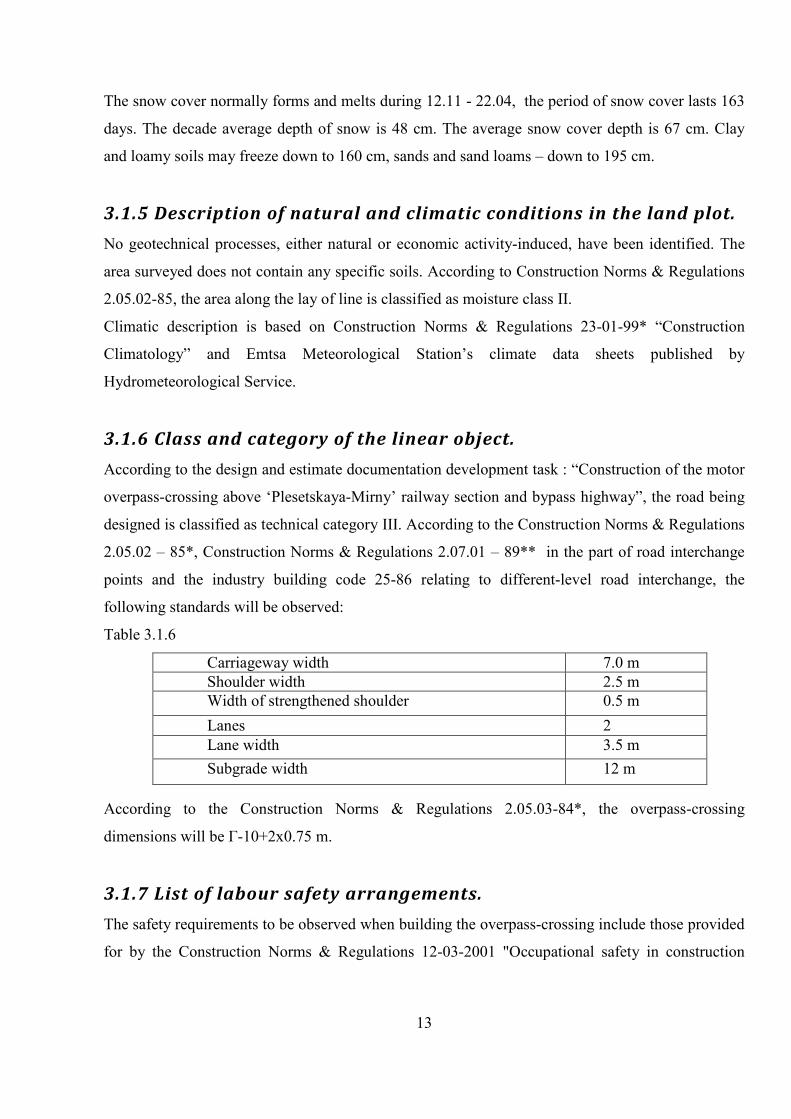
Table 3.1.6
According to the Construction Norms & Regulations 2.05.03-84*, the overpass-crossing
dimensions will be Г-10+2х0.75 m.
3.1.7 List of labour safety arrangements. The safety requirements to be observed when building the overpass-crossing include those provided
for by the Construction Norms & Regulations 12-03-2001 "Occupational safety in construction
Carriageway width 7.0 m Shoulder width 2.5 m Width of strengthened shoulder 0.5 m Lanes 2 Lane width 3.5 m Subgrade width 12 m
14
industry: Part 1. General Requirements" and Construction Norms & Regulations 12-04-2002
"Occupational safety in construction industry: Part 2. Construction Operations".
Relevant operation manuals will be used when operating the machinery. Cranes operation will be
governed by work production plan, crane operating instructions, Procedure for Design and Safe
Operation of Cargo Cranes, Safety Rules ПБ-10-14-92 of RF State Committee for Industrial and
Mining Safety Supervision. The crane radius will be selected in accordance with the cargo capacity
curves specified in the crane certificate.
3.1.8 Overpass-crossing technological and structural concept. According to the design and estimate documentation development task, the section of the road
being designed is classified as technical category III. The overpass-crossing dimensions: Г-
10+2х0.75 m. The design of the overpass-crossing underclearance is governed by condition that
the superstructure must be elevated above the rail head at least 8.5 m, as provided for by JSC
“Russian Railways” requirements. The bridge span is designed on the basis of cones dimensions
and requirement to ensure the minimum distance between the overhead wires and the overpass-
crossing supports, as provided by requirements of the Table 2.2.2 of the “Procedure for design and
operation of electric railway overhead system”.
Given the above requirements, three design alternatives of the overpass-crossing have been
proposed.
3.1.9 Descriptions of the overpass-crossing designs. Design 1.
Overpass-crossing: 18.0+33.0+24.0 m. The calculated length of mid-span – 33 m – is determined to
meet the requirement to secure a 4-meter distance between the overhead system wires and supports.
The length of span No.1 – 18 m – is determined on the basis of the cone dimensions. The length of
span No.3 – 24 m – is determined to meet the requirement to secure the required distances from the
intermediate support and cone surface to Overhead Line-10 kV, AB and PE that runs along this
span. The superstructure is a precast concrete element made of pre-tensioned girders, TC series
3.503.1-81. The abutments are buried, reinforced concrete, cast-in-place, bearings pile, spill-
through type, independent structures. The intermediate piers are concrete structures, bearing pile,
independent structures according to TC 3.503.1-60.
15
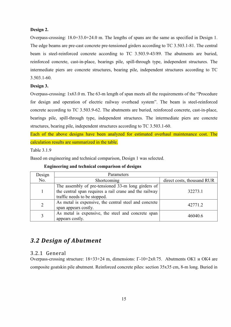
Design 2.
Overpass-crossing: 18.0+33.0+24.0 m. The lengths of spans are the same as specified in Design 1.
The edge beams are pre-cast concrete pre-tensioned girders according to TC 3.503.1-81. The central
beam is steel-reinforced concrete according to TC 3.503.9-43/89. The abutments are buried,
reinforced concrete, cast-in-place, bearings pile, spill-through type, independent structures. The
intermediate piers are concrete structures, bearing pile, independent structures according to TC
3.503.1-60.
Design 3.
Overpass-crossing: 1х63.0 m. The 63-m length of span meets all the requirements of the “Procedure
for design and operation of electric railway overhead system”. The beam is steel-reinforced
concrete according to TC 3.503.9-62. The abutments are buried, reinforced concrete, cast-in-place,
bearings pile, spill-through type, independent structures. The intermediate piers are concrete
structures, bearing pile, independent structures according to TC 3.503.1-60.
Each of the above designs have been analyzed for estimated overhaul maintenance cost. The
calculation results are summarized in the table.
Table 3.1.9
Based on engineering and technical comparison, Design 1 was selected.
Engineering and technical comparison of designs
Design No.
Parameters Shortcoming direct costs, thousand RUR
1 The assembly of pre-tensioned 33-m long girders of the central span requires a rail crane and the railway traffic needs to be stopped.
32273.1
2 As metal is expensive, the central steel and concrete span appears costly. 42771.2
3 As metal is expensive, the steel and concrete span appears costly. 46040.6
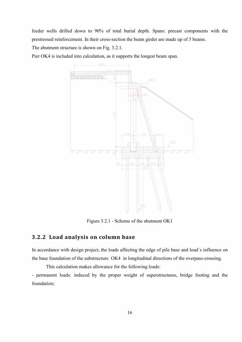
3.2 Design of Abutment 3.2.1 General Overpass-crossing structure: 18+33+24 m, dimensions: Г-10+2х0.75. Abutments ОК1 и ОК4 are
composite goatskin pile abutment. Reinforced concrete piles: section 35х35 cm, 8-m long. Buried in
16
feeder wells drilled down to 90% of total burial depth. Spans: precast components with the
prestressed reinforcement. In their cross-section the beam girder are made up of 5 beams.
The abutment structure is shown on Fig. 3.2.1.
Pier OK4 is included into calculation, as it supports the longest beam span.
Figure 3.2.1 - Scheme of the abutment OK1
3.2.2 Load analysis on column base In accordance with design project, the loads affecting the edge of pile base and load´s influence on
the base foundation of the substructure ОK4 in longitudinal directions of the overpass-crossing.
This calculation makes allowance for the following loads:
- permanent loads: induced by the proper weight of superstructures, bridge footing and the
foundation;
17
- temporary loads: vertical (induced by carrying equipment and pedestrian flow; horizontal
longitudinal (induced by braking action).
3.2.2.1 Permanent loads Support reaction from weight of the beam span
The analysis of constant loads is to be carried out on the basis of half-spans with total length
24/2 = 12,0 𝑚
1) Weight of bridge deck
The weight of bridge deck is estimated according to the formula (2.1):
𝐺пок = 𝐿𝑏 ⋅ 𝐵 ⋅ � ℎпок 𝑖 ⋅ 𝑚𝑖 ⋅ 𝑔𝑛
𝑖=1
where Lb – length of span section under consideration, m, Lb = 12.0 m;
Bi – width of span, m;
hi – breadth of bridge, m;
𝑚𝑖- weight of i - layer, kg;
g – free fall acceleration, N/kg, g = 9.81.
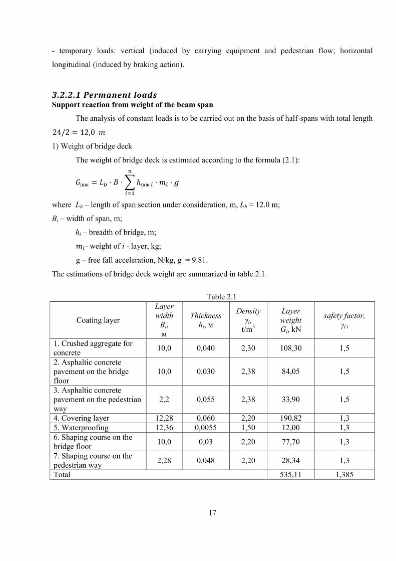
The estimations of bridge deck weight are summarized in table 2.1.
Table 2.1
Coating layer
Layer width
Bi, м
Thickness hi, м
Density γi,
t/m3
Layer weight Gi, kN
safety factor, γf i
1. Crushed aggregate for concrete 10,0 0,040 2,30 108,30 1,5
2. Asphaltic concrete pavement on the bridge floor
10,0 0,030 2,38 84,05 1,5
3. Asphaltic concrete pavement on the pedestrian way
2,2 0,055 2,38 33,90 1,5
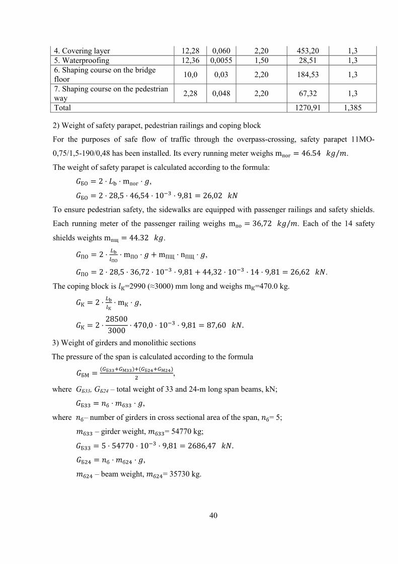
4. Covering layer 12,28 0,060 2,20 190,82 1,3 5. Waterproofing 12,36 0,0055 1,50 12,00 1,3 6. Shaping course on the bridge floor 10,0 0,03 2,20 77,70 1,3
7. Shaping course on the pedestrian way 2,28 0,048 2,20 28,34 1,3
Total 535,11 1,385
18
2) Weight of safety parapet, pedestrian railings and coping block
For the purposes of safe flow of traffic through the overpass-crossing, safety parapet 11МО-
0,75/1,5-190/0,48 has been installed. Its every running meter weighs mпог = 46.54 𝑘𝑔/𝑚.
The weight of safety parapet is calculated according to the formula:
𝐺БО = 2 ⋅ 𝐿b ⋅ mпог ⋅ 𝑔,
𝐺БО = 2 ⋅ 12,0 ⋅ 46,54 ⋅ 10−3 ⋅ 9,81 = 10,95 𝑘𝑁
To ensure pedestrian safety, the sidewalks are equipped with railings and safety shields. Each
running meter of the railing weighs mпог = 36,72 𝑘𝑔/𝑚.
𝐺ПО = 2 ⋅𝐿b
𝑙ПО⋅ mПО ⋅ 𝑔
𝐺ПО = 2 ⋅ 12 ⋅ 36,72 ⋅ 10−3 ⋅ 9,81 = 8,65 𝑘𝑁
The coping block is 𝑙К=2990 (≈3000) mm long and weighs mК=470.0 kg
𝐺К = 2 ⋅𝐿𝑏
𝑙К⋅ 𝑚К ⋅ 𝑔
𝐺К = 2 ⋅120003000
⋅ 470,0 ⋅ 10−3 ⋅ 9,81 = 36,89 𝑘𝑁.
3) Weight of beam girder and monolithic sections
The load of the span is calculated according to the formula
𝐺БМ =𝐺Б24 + 𝐺М24
2
where GБ24 – total weight of 33 and 24-m long girders, kN;
𝐺Б24 = 𝑛б ⋅ 𝑚б24 ⋅ 𝑔
where 𝑛б– number of units in cross sectional area of the span, 𝑛б= 5;
𝑚б24 – girder weight, 𝑚б24= 35730 kg.
𝐺Б24 = 5 ⋅ 35730 ⋅ 10−3 ⋅ 9,81 = 1752,56 𝑘𝑁
GM24 - total weight of built-in monolithic supports, kN;
𝐺М24 = 𝐺МС24 + 𝐺МК24
where GМС24, GМК24 – weight of edge and middle beams, respectively, kN.
𝐺МС24 = 𝑛𝑉МС24 ⋅ γжб
where n – number of monolithic mid-beams, n = 4;
𝑉МС24 - volume of monolithic mid-section, m3, 𝑉МС24 = 4,32 𝑚3;
γжб - specific weight of reinforced concrete, γжб = 2,5 t/m3.
𝐺МС24 = 4 ⋅ 4,32 ⋅ 2,5 ⋅ 9,81 = 423,79 kN;
19
𝐺МК24 = 𝑛𝑉МК24 ⋅ γжб,
where n – number of edge monolithic beams, n = 2;
𝑉МС33- volume of edge monolithic beams, 𝑉МК33 = 2,75 м3;
𝐺МК24 = 2 ⋅ 2,75 ⋅ 2,5 ⋅ 9,81 = 134,89 kN;
𝐺БМ =1752,56 + 423,79 + 134,89
2= 1155,62 𝑘𝑁.
The pressure of the superstructure with the safety factor γ𝑓 = 1,1:
𝐺БМ = 1,1 ⋅ 1155,62 = 1271,18 𝑘𝑁. Vertical load from the weight of the superstructure
- Weight of footing 𝐺Р, kN, to be calculated according to the formula:
𝐺Р = 𝑉Р ⋅ γжб ⋅ 𝑔,
where Vp – footing volume, Vp = 18,88 m3;
Gp = 18,88 ∙ 2,5 ∙ 9,81 = 463,03 kN.
- Weight of pedestals 𝐺п, kN:
𝐺п = 𝑉п ⋅ γЖБ ⋅ 𝑔,
where Vп – pedestals volume, Vп = 0,81 м3;
𝐺п = 0,81 ⋅ 2,5 ⋅ 9,81 = 19,87 kN.
- Weight of the back wall 𝐺шс, kN:
𝐺шс = 𝑉шс ⋅ γЖБ ⋅ 𝑔,
where Vшс – back wall volume, Vшс = 16,07 м3;
𝐺шс = 16,07 ⋅ 2,5 ⋅ 9,81 = 394,12 kN.
- Weight of wing wall 𝐺о, kN:
𝐺о = 𝑛𝑉о ⋅ γЖБ ⋅ 𝑔,
where Vо – volume of wing wall, Vо = 1,47 m3;
n – number of wings, n = 2.
𝐺шс = 2 ⋅ 1,47 ⋅ 2,5 ⋅ 9,81 = 72,10 kN.
- Weight of vertical columns, 𝐺вс, kN:
𝐺вс = 𝑛𝑉вс ⋅ γЖБ ⋅ 𝑔,
where Vвс – volume of vertical columns, Vвс = 3,60 m3;
n – number of columns, n = 5.
𝐺вс = 5 ⋅ 3,60 ⋅ 2,5 ⋅ 9,81 = 441,45 kN.
- Weight of sweep columns,𝐺нс, kN:
20
𝐺нс = 𝑛𝑉нс ⋅ γЖБ ⋅ 𝑔,
where Vнс – volume of sweep columns, Vнс = 1,15 m3;
n – number of columnss, n = 5.
𝐺нс = 5 ⋅ 1,15 ⋅ 2,5 ⋅ 9,81 = 141,02 kN
Vertical load from weight of the substructure with the safety factor:
𝐺 = (463,03 + 19,87 + 394,12 + 72,10 + 441,45 + 141,02) ⋅ 1,1 = 1684,75 𝑘𝑁
3.2.2.2 Temporary loads Load from two carriage bogies A-14 on span bridge
The bridge columns are situated under girders, and each column has the same temporary load as a
girder, so they have identical transverse installation values. The most heavily loaded component is
the middle beam-girder with the following values: КПУА = 0,637 и КПУАт = 0,734.
Temporary load of 2 carriage bogies А-14:
- standard:
𝐺А−14,𝑛 = КПУАт ⋅ 𝑞э𝜔 + КПУА ⋅ 𝑞пол ⋅ 𝜔,
where ω- influence line area, m2:
𝜔 = 0,5 ⋅ 1 ⋅ 24 = 12 𝑚2.
𝑞пол - lane load tape А-14, 𝑞пол= 14 kN/м;
𝑞э- uniformly distributed load by one carriage bogie, kN/м:
𝑞э =РАт ∑ 𝑦𝑖
2𝑖=1
ω
𝑞э =14012
�1 +24 − 1,5
24� = 22,60 𝑘𝑁/𝑚
𝐺А−14,𝑛 = 0,734 ⋅ 22,60 ⋅ 12 + 0,637 ⋅ 14 ⋅ 12 = 306,08 𝑘𝑁.
- computational:
Dynamic coefficients 1+µ for loads imposed by highway and road traffic are taken up as equal::
1 + 𝜇 = 1 + 45−𝜆135
,but not less 1,0
1 + 𝜇 = 1 +45 − 24
135= 1,16.
𝐺А−14 = (1 + 𝜇)�𝛾𝑓,𝐴т ⋅ КПУАт ⋅ 𝑞э ⋅ 𝜔 + 𝛾𝑓,𝐴 ⋅ КПУА ⋅ 𝑞пол ⋅ 𝜔�,
𝐺А−14 = 1,16 ⋅ (1,27 ⋅ 0,734 ⋅ 22,60 ⋅ 12 + 1,2 ⋅ 0,637 ⋅ 14 ⋅ 12) = 442,22 𝑘𝑁.
21
Horizontal load induced by braking forces А-14 It is assumed that only vehicles moving in the same direction brake, i.e. braking load acts from the
same traffic lane. Therefore lane factor for distributed lane load is not applied.
Weight of the standard distributed lane load:
Р = 𝑞пол𝑙2,
𝑃 = 14 242
= 168 𝑘𝑁,
Total standard value of braking load:
𝐺ℎ,𝑛 = 0,5𝑃,
But no less than: 𝐺ℎ,𝑛 = 0,8𝑃Ат = 0,8 ⋅ 140 = 112,0 𝑘𝑁;
𝐺ℎ,𝑛 = 0,5 ⋅ 168 = 84 𝑘𝑁.
Therefore, total standard load value of braking: 𝐺ℎ,𝑛 = 112,0 𝑘𝑁;
Standard moment of force 𝐺ℎ,𝑛 equal:
𝑀𝑛 = 𝐺ℎ,𝑛ℎ,
where h - arm of braking force between the top of carriageway and design section:
h = 10,26 m;
𝑀𝑛 = 112,0 ⋅ 10,26 = 1149,12 𝑘𝑁𝑚.
Design value of force and moment:
𝐹ℎ = 1,2 ⋅ 112 = 134,40 𝑘𝑁
𝑀 = 1,2 ⋅ 1149,12 = 1378,94 𝑘𝑁𝑚.
Design value of force and moment, acting onto frame:
𝐹ℎ,р =134,40
5= 26,88 𝑘𝑁.
𝑀р =1378,94
5= 275,79 𝑘𝑁𝑚.
Horizontal earth pressure influence on abutment from dead earth weight
Average width of bridge abutment equal:
𝐵 =В1ℎ1 + В2ℎ2
ℎ1 + ℎ2
where В1 – thickness of back wall, В1 = 12,83 m;
h1 – height of back wall, h1 = 2,56 m;
В2 – width of column bent, В2 = 5,0 m;
22
h2 – height of columns in a vertical row, h2 = 7,67 m.
В =12,83 ⋅ 2,56 + 5,0 ⋅ 7,67
2,56 + 7,67= 6,96 𝑚.
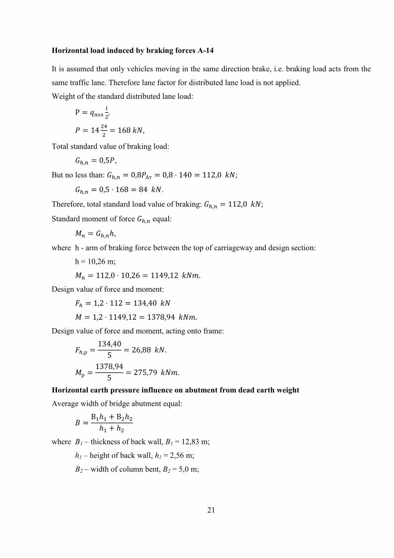
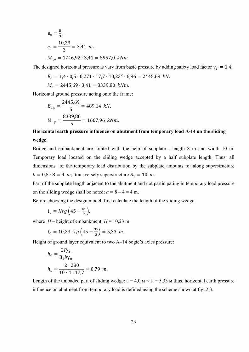
The horizontal earth pressure is calculated according to the following scheme
on fig. 3.2.2.2 - 1:
Figure 3.2.2.2 - 1 - Loading system
Pressure ratio is calculated by:
𝜇 = 𝑡𝑔2𝜔𝑜,
where 𝑡𝑔 ⋅ ω𝑜 - dangerous slope of collapse to vertical:
𝑡𝑔𝜔𝑜 = 𝑡𝑔 �45𝑜 − 𝜑п2
�,
where φп - standard angle of internal friction, φп = 35𝑜;
𝑡𝑔ω𝑜 = 𝑡𝑔 �45𝑜 −35𝑜
2� = 0,52.
𝜇 = 𝑡𝑔20,52 = 0,271.
Basic earth pressure is equal:
𝐸𝑜,𝑛 = 0,5μγ𝑛𝐻2𝐵,
where γ𝑛- unit density of ground cone , γ𝑛 = 17,7 𝑘𝑁/𝑚3;
𝐸𝑜,𝑛 = 0,5 ⋅ 0,271 ⋅ 17,7 ⋅ 10,232 ⋅ 6,96 = 1746,92 𝑘𝑁.
Earth pressure moment:
𝑀о,п = 𝐸о,п ⋅ 𝑒о,
where ео- moment arm of Ео,п, m:
23
ео = Н3 ,
ео =10,23
3= 3,41 𝑚.
Мо,п = 1746,92 ⋅ 3,41 = 5957,0 𝑘𝑁𝑚
The designed horizontal pressure is vary from basic pressure by adding safety load factor γ𝑓 = 1,4. 𝐸𝑜 = 1,4 ⋅ 0,5 ⋅ 0,271 ⋅ 17,7 ⋅ 10,232 ⋅ 6,96 = 2445,69 𝑘𝑁.
Мо = 2445,69 ⋅ 3,41 = 8339,80 𝑘𝑁𝑚.
Horizontal ground pressure acting onto the frame:
𝐸𝑜,р =2445,69
5= 489,14 𝑘𝑁.
Мо,р =8339,80
5= 1667,96 𝑘𝑁𝑚.
Horizontal earth pressure influence on abutment from temporary load A-14 on the sliding
wedge
Bridge and embankment are jointed with the help of subplate - length 8 m and width 10 m.
Temporary load located on the sliding wedge accepted by a half subplate length. Thus, all
dimensions of the temporary load distribution by the subplate amounts to: along superstructure
𝑏 = 0,5 ⋅ 8 = 4 𝑚; transversely superstructure 𝐵1 = 10 𝑚.
Part of the subplate length adjacent to the abutment and not participating in temporary load pressure
on the sliding wedge shall be noted: а = 8 – 4 = 4 m.
Before choosing the design model, first calculate the length of the sliding wedge:
𝑙𝑜 = 𝐻𝑡𝑔 �45 − φп2
�,
where H – height of embankment, H = 10,23 m;
𝑙𝑜 = 10,23 ⋅ 𝑡𝑔 �45 − 352
� = 5,33 𝑚.
Height of ground layer equivalent to two А–14 bogie’s axles pressure:
ℎ𝑜 =2𝑃Ат
В1𝑏γ𝑛
ℎ𝑜 =2 ⋅ 280
10 ⋅ 4 ⋅ 17,7= 0,79 𝑚.
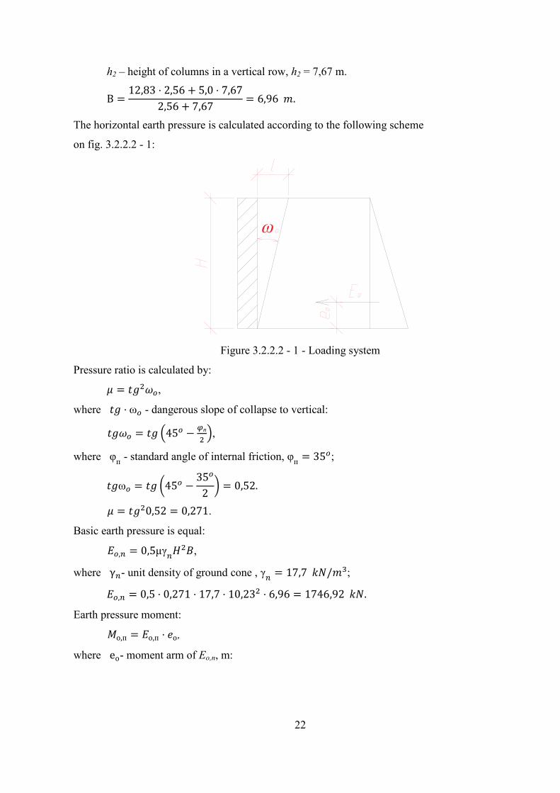
Length of the unloaded part of sliding wedge: а = 4,0 м < lо = 5,33 м thus, horizontal earth pressure
influence on abutment from temporary load is defined using the scheme shown at fig. 2.3.
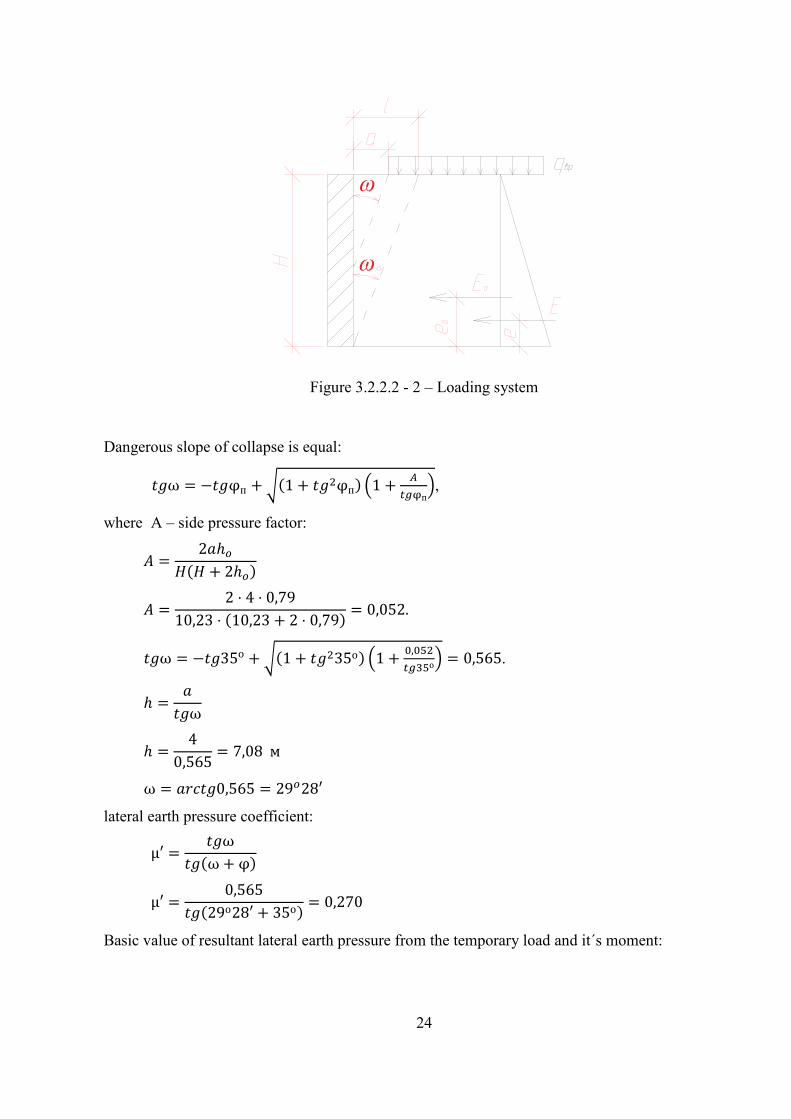
24
Figure 3.2.2.2 - 2 – Loading system
Dangerous slope of collapse is equal:
𝑡𝑔ω = −𝑡𝑔φп + �(1 + 𝑡𝑔2φп) �1 + 𝐴𝑡𝑔φп
�,
where А – side pressure factor:
𝐴 =2𝑎ℎ𝑜
𝐻(𝐻 + 2ℎ𝑜)
𝐴 =2 ⋅ 4 ⋅ 0,79
10,23 ⋅ (10,23 + 2 ⋅ 0,79) = 0,052.
𝑡𝑔ω = −𝑡𝑔35о + �(1 + 𝑡𝑔235о) �1 + 0,052𝑡𝑔35о� = 0,565.
ℎ =𝑎
𝑡𝑔ω
ℎ =4
0,565= 7,08 м
ω = 𝑎𝑟𝑐𝑡𝑔0,565 = 29𝑜28′
lateral earth pressure coefficient:
µ′ =𝑡𝑔ω
𝑡𝑔(ω + φ)
µ′ =0,565
𝑡𝑔(29о28′ + 35о) = 0,270
Basic value of resultant lateral earth pressure from the temporary load and it´s moment:
25
𝐸𝑛 = γ𝑛ℎ𝑜(𝐻 − ℎ)µ′𝐵
𝑀𝑛 = 𝐸𝑜,𝑛 ⋅𝐻 − ℎ
2
𝐸𝑛 = 17,7 ⋅ 0,79 ⋅ (10,23 − 7,08) ⋅ 0,270 ⋅ 5 = 59,46 𝑘𝑁
𝑀𝑛 = 59,46 ⋅10,23 − 7,08
2 = 93,65 kN𝑚
Design value of resultant lateral earth pressure from the temporary load and it´s moment:
𝐸 = 1,4 ⋅ 59,46 = 83,24 𝑘𝑁.
𝑀 = 1,4 ⋅ 93,65 = 131,11 𝑘𝑁𝑚.
Basic value of resultant lateral earth pressure from the temporary load and it´s moment which are
acted on frame:
𝐸р =83,24
5= 16,65 𝑘𝑁
𝑀р =131,11
5= 26,22 𝑘𝑁𝑚
Height of ground layer, which is equivalent load pressure of 2 bogies A-14:
ℎ𝑜 =(1 + 0,6)𝑞пол
В1γ𝑛
ℎ𝑜 =1,6 ⋅ 14
10 ⋅ 17,7= 0,13 𝑚
𝐴 =2 ⋅ 4 ⋅ 0,13
10,23 ⋅ (10,23 + 2 ⋅ 0,13) = 0,010
𝑡𝑔ω = −𝑡𝑔35о + �(1 + 𝑡𝑔235о) �1 +0,010𝑡𝑔35о
� = 0,529
ℎ =4
0,529= 7,56 𝑚
ω = 𝑎𝑟𝑐𝑡𝑔0,529 = 27𝑜53′
μ′ =0,529
𝑡𝑔(27о53′ + 35о) = 0,271
Basic value of resultant lateral earth pressure from the temporary load and it´s moment:
𝐸𝑛 = 17,7 ⋅ 0,17 ⋅ (10,23 − 7,52) ⋅ 0,271 ⋅ 5,0 = 11,05 𝑘𝑁.
𝑀𝑛 = 11,05 ⋅10,23 − 7,52
2= 14,97 𝑘𝑁𝑚
Design value of resultant lateral earth pressure from the temporary load and it´s moment:
26
𝐸 = 1,4 ⋅ 11,05 = 15,47 𝑘𝑁.
𝑀 = 1,4 ⋅ 14,97 = 20,96 𝑘𝑁𝑚.
Basic value of resultant lateral earth pressure from the temporary load and it´s moment which are
acted on frame:
𝐸 =15,47
5= 3,09 𝑘𝑁
𝑀 =20,96
5= 4,19 𝑘𝑁𝑚
Resultant action from bogie and lane load:
𝐸𝑟𝑒𝑠 = 𝐸𝑝 + 𝐸 = 16,65 + 3,09 = 19,74 𝑘𝑁;М𝑟𝑒𝑠 = 𝑀𝑝 + 𝑀 = 26,22 + 4,19 = 30,41 𝑘𝑁𝑚.
Forces acting along column base edge onto a single frame of abutment are listed in table 2.2.
Table 3.2.2.2 – Summary table of forces acting along column base edge onto a single frame of abutment
Force Rated force
vertical N, kN
horizontal Н, kN
Substructure weight 336,95 - Superstructure weight 391,78 - Reaction from А14 on the span 88,44 - Braking А14 - 5,38 Pressure from ground weight onto abutment - 97,83
Pressure onto abutment from A14 - 3,95 Total 817,17 107,15
3.2.3 Loads acting along the foundation slab 3.2.3.1 Permanent loads Support reaction from superstructure weight
Loads of this type are aggregated calculating on a half span length 24/2 = 12.0 𝑚.
1) Bridge deck weight
The weight of bridge deck is estimated according to the formula (2.1):
𝐺пок = 𝐿𝑏 ⋅ 𝐵 ⋅ � ℎпок 𝑖 ⋅ 𝑚𝑖 ⋅ 𝑔𝑛
𝑖=1
where Lb – length of span section under consideration, m, Lb = 12.0 m;
27
Bi – width of span, m;
hi – breadth of bridge, m;
𝑚𝑖- weight of i - layer, kg;
g – free fall acceleration, N/kg, g = 9.81.
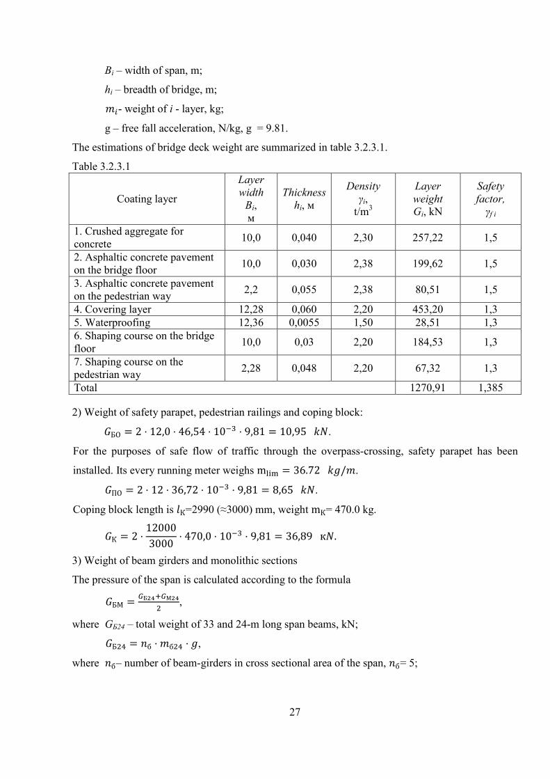
The estimations of bridge deck weight are summarized in table 3.2.3.1.
Table 3.2.3.1
Coating layer
Layer width
Bi, м
Thickness hi, м
Density γi,
t/m3
Layer weight Gi, kN
Safety factor, γf i
1. Crushed aggregate for concrete 10,0 0,040 2,30 257,22 1,5
2. Asphaltic concrete pavement on the bridge floor 10,0 0,030 2,38 199,62 1,5
3. Asphaltic concrete pavement on the pedestrian way 2,2 0,055 2,38 80,51 1,5
4. Covering layer 12,28 0,060 2,20 453,20 1,3 5. Waterproofing 12,36 0,0055 1,50 28,51 1,3 6. Shaping course on the bridge floor 10,0 0,03 2,20 184,53 1,3
7. Shaping course on the pedestrian way 2,28 0,048 2,20 67,32 1,3
Total 1270,91 1,385
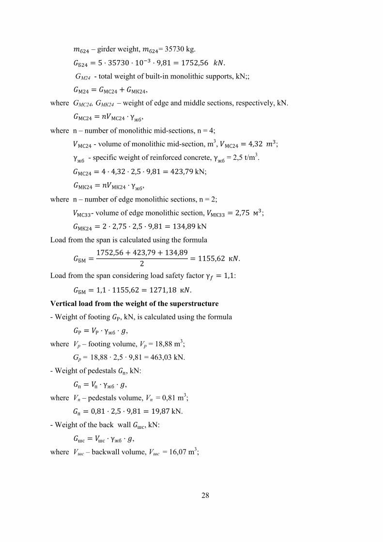
2) Weight of safety parapet, pedestrian railings and coping block:
𝐺БО = 2 ⋅ 12,0 ⋅ 46,54 ⋅ 10−3 ⋅ 9,81 = 10,95 𝑘𝑁.
For the purposes of safe flow of traffic through the overpass-crossing, safety parapet has been
installed. Its every running meter weighs mlim = 36.72 𝑘𝑔/𝑚.
𝐺ПО = 2 ⋅ 12 ⋅ 36,72 ⋅ 10−3 ⋅ 9,81 = 8,65 𝑘𝑁.
Coping block length is 𝑙К=2990 (≈3000) mm, weight mК= 470.0 kg.
𝐺К = 2 ⋅120003000
⋅ 470,0 ⋅ 10−3 ⋅ 9,81 = 36,89 к𝑁.
3) Weight of beam girders and monolithic sections
The pressure of the span is calculated according to the formula
𝐺БМ = 𝐺Б24+𝐺М242
,
where GБ24 – total weight of 33 and 24-m long span beams, kN;
𝐺Б24 = 𝑛б ⋅ 𝑚б24 ⋅ 𝑔,
where 𝑛б– number of beam-girders in cross sectional area of the span, 𝑛б= 5;
28
𝑚б24 – girder weight, 𝑚б24= 35730 kg.
𝐺Б24 = 5 ⋅ 35730 ⋅ 10−3 ⋅ 9,81 = 1752,56 𝑘𝑁.
GM24 - total weight of built-in monolithic supports, kN;;
𝐺М24 = 𝐺МС24 + 𝐺МК24,
where GМС24, GМК24 – weight of edge and middle sections, respectively, kN.
𝐺МС24 = 𝑛𝑉МС24 ⋅ γжб,
where n – number of monolithic mid-sections, n = 4;
𝑉МС24 - volume of monolithic mid-section, m3, 𝑉МС24 = 4,32 𝑚3;
γжб - specific weight of reinforced concrete, γжб = 2,5 t/m3.
𝐺МС24 = 4 ⋅ 4,32 ⋅ 2,5 ⋅ 9,81 = 423,79 kN;
𝐺МК24 = 𝑛𝑉МК24 ⋅ γжб,
where n – number of edge monolithic sections, n = 2;
𝑉МС33- volume of edge monolithic section, 𝑉МК33 = 2,75 м3;
𝐺МК24 = 2 ⋅ 2,75 ⋅ 2,5 ⋅ 9,81 = 134,89 kN
Load from the span is calculated using the formula
𝐺БМ =1752,56 + 423,79 + 134,89
2= 1155,62 к𝑁.
Load from the span considering load safety factor γ𝑓 = 1,1:
𝐺БМ = 1,1 ⋅ 1155,62 = 1271,18 к𝑁.
Vertical load from the weight of the superstructure
- Weight of footing 𝐺Р, kN, is calculated using the formula
𝐺Р = 𝑉Р ⋅ γжб ⋅ 𝑔,
where Vp – footing volume, Vp = 18,88 m3;
Gp = 18,88 ∙ 2,5 ∙ 9,81 = 463,03 kN.
- Weight of pedestals 𝐺п, kN:
𝐺п = 𝑉п ⋅ γжб ⋅ 𝑔,
where Vп – pedestals volume, Vп = 0,81 m3;
𝐺п = 0,81 ⋅ 2,5 ⋅ 9,81 = 19,87 kN.
- Weight of the back wall 𝐺шс, kN:
𝐺шс = 𝑉шс ⋅ γжб ⋅ 𝑔,
where Vшс – backwall volume, Vшс = 16,07 m3;
29
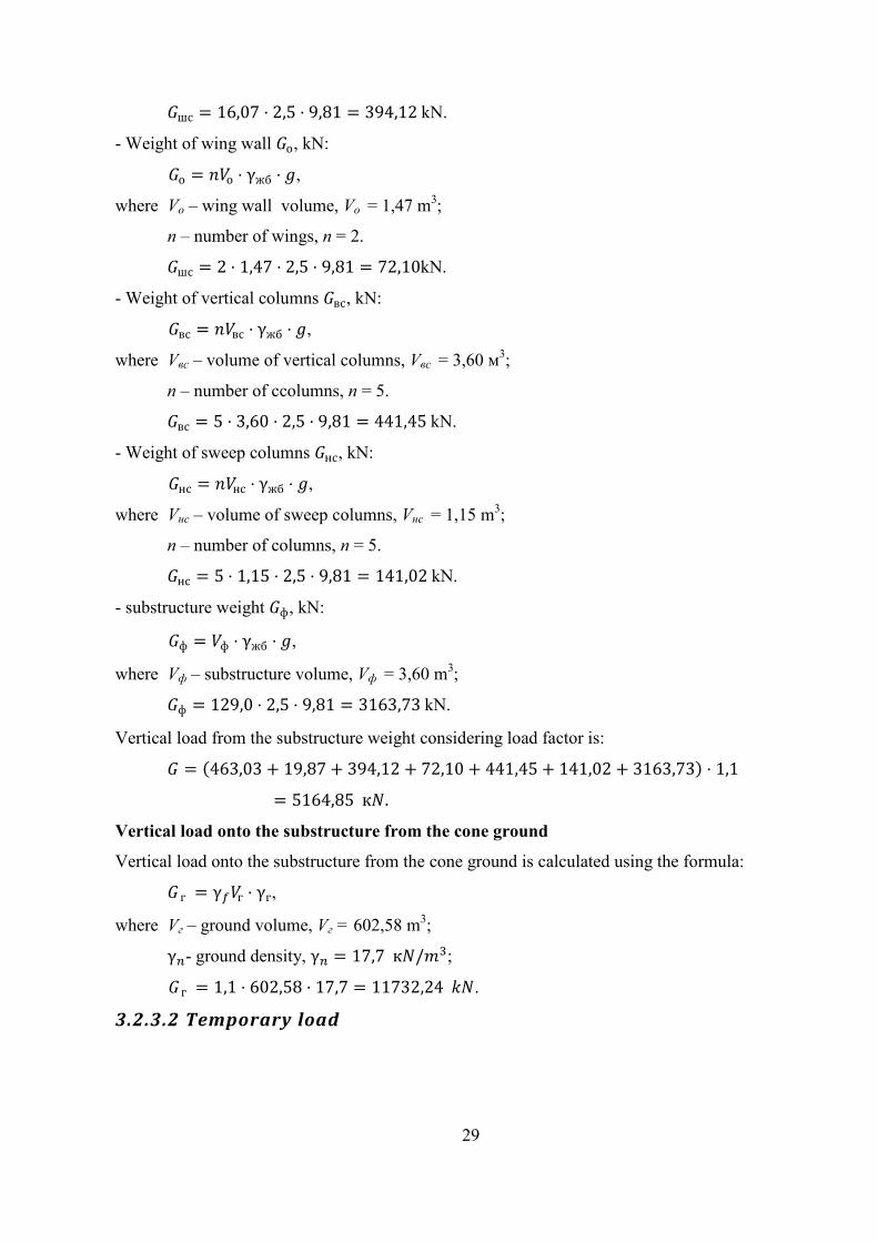
𝐺шс = 16,07 ⋅ 2,5 ⋅ 9,81 = 394,12 kN.
- Weight of wing wall 𝐺о, kN:
𝐺о = 𝑛𝑉о ⋅ γжб ⋅ 𝑔,
where Vо – wing wall volume, Vо = 1,47 m3;
n – number of wings, n = 2.
𝐺шс = 2 ⋅ 1,47 ⋅ 2,5 ⋅ 9,81 = 72,10kN.
- Weight of vertical columns 𝐺вс, kN:
𝐺вс = 𝑛𝑉вс ⋅ γжб ⋅ 𝑔,
where Vвс – volume of vertical columns, Vвс = 3,60 м3;
n – number of ccolumns, n = 5.
𝐺вс = 5 ⋅ 3,60 ⋅ 2,5 ⋅ 9,81 = 441,45 kN.
- Weight of sweep columns 𝐺нс, kN:
𝐺нс = 𝑛𝑉нс ⋅ γжб ⋅ 𝑔,
where Vнс – volume of sweep columns, Vнс = 1,15 m3;
n – number of columns, n = 5.
𝐺нс = 5 ⋅ 1,15 ⋅ 2,5 ⋅ 9,81 = 141,02 kN.
- substructure weight 𝐺ф, kN:
𝐺ф = 𝑉ф ⋅ γжб ⋅ 𝑔,
where Vф – substructure volume, Vф = 3,60 m3;
𝐺ф = 129,0 ⋅ 2,5 ⋅ 9,81 = 3163,73 kN.
Vertical load from the substructure weight considering load factor is:
𝐺 = (463,03 + 19,87 + 394,12 + 72,10 + 441,45 + 141,02 + 3163,73) ⋅ 1,1
= 5164,85 к𝑁.
Vertical load onto the substructure from the cone ground
Vertical load onto the substructure from the cone ground is calculated using the formula:
𝐺 г = γ𝑓𝑉г ⋅ γг,
where Vг – ground volume, Vг = 602,58 m3;
γ𝑛- ground density, γ𝑛 = 17,7 к𝑁/𝑚3;
𝐺 г = 1,1 ⋅ 602,58 ⋅ 17,7 = 11732,24 𝑘𝑁.
3.2.3.2 Temporary load
30
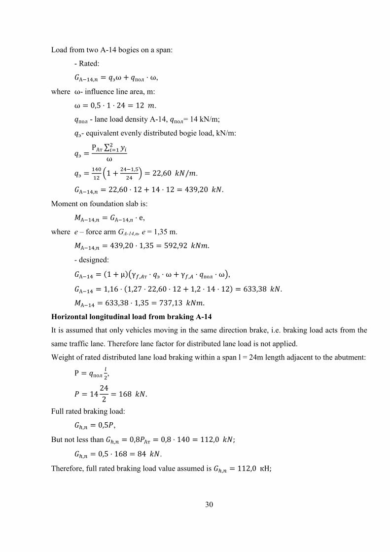
Load from two А-14 bogies on a span:
- Rated:
𝐺А−14,𝑛 = 𝑞эω + 𝑞пол ⋅ ω,
where ω- influence line area, m:
ω = 0,5 ⋅ 1 ⋅ 24 = 12 𝑚.
𝑞пол - lane load density А-14, 𝑞пол= 14 kN/m;
𝑞э- equivalent evenly distributed bogie load, kN/m:
𝑞э =РАт ∑ 𝑦𝑖
2𝑖=1
ω
𝑞э = 14012
�1 + 24−1,524
� = 22,60 𝑘𝑁/𝑚.
𝐺А−14,𝑛 = 22,60 ⋅ 12 + 14 ⋅ 12 = 439,20 𝑘𝑁.
Moment on foundation slab is:
𝑀А−14,𝑛 = 𝐺А−14,п ⋅ е,
where е – force arm GА-14,п, е = 1,35 m.
𝑀А−14,𝑛 = 439,20 ⋅ 1,35 = 592,92 𝑘𝑁𝑚.
- designed:
𝐺А−14 = (1 + µ)�γ𝑓,𝐴т ⋅ 𝑞э ⋅ ω + γ𝑓,𝐴 ⋅ 𝑞пол ⋅ ω�,
𝐺А−14 = 1,16 ⋅ (1,27 ⋅ 22,60 ⋅ 12 + 1,2 ⋅ 14 ⋅ 12) = 633,38 𝑘𝑁.
𝑀А−14 = 633,38 ⋅ 1,35 = 737,13 𝑘𝑁𝑚. Horizontal longitudinal load from braking А-14
It is assumed that only vehicles moving in the same direction brake, i.e. braking load acts from the
same traffic lane. Therefore lane factor for distributed lane load is not applied.
Weight of rated distributed lane load braking within a span l = 24m length adjacent to the abutment:
Р = 𝑞пол𝑙2,
𝑃 = 14242
= 168 𝑘𝑁.
Full rated braking load:
𝐺ℎ,𝑛 = 0,5𝑃,
But not less than 𝐺ℎ,𝑛 = 0,8𝑃Ат = 0,8 ⋅ 140 = 112,0 𝑘𝑁;
𝐺ℎ,𝑛 = 0,5 ⋅ 168 = 84 𝑘𝑁.
Therefore, full rated braking load value assumed is 𝐺ℎ,𝑛 = 112,0 кН;
31
Rated moment of 𝐺ℎ,𝑛 is:
𝑀𝑛 = 𝐺ℎ,𝑛ℎ,
where h - arm of braking force between the top of roadway surface and calculated section,
h = 12,61 m;
𝑀𝑛 = 112,0 ⋅ 12,61 = 1412,32 𝑘𝑁𝑚.
Rated force and moment values of 𝐺ℎ,𝑛:
𝐹ℎ = 1,2 ⋅ 112 = 134,40 𝑘𝑁.
𝑀 = 1,2 ⋅ 1412,32 = 1694,78 𝑘𝑁𝑚. Horizontal earth pressure onto a abutment from dead cone ground weight
Average abutment width normalized by height is calculated using the formula:
В =В1ℎ1 + В2ℎ2 + В3ℎ3 + В4ℎ4
ℎ1 + ℎ2 + ℎ3 + ℎ4
where В1 – width of back wall, В1 = 12,83 m;
h1 – back wall height, h1 = 2,56 m;
В2 – width of column bent, В2 = 5,0 m;
h2 – height of columns in a vertical row, h2 = 7,67 m;
В3 – bearing width by column bases, В3 = 6,50 m;
h3 – height of column base, h3 = 0,65 m;
В4 – foundation slab height, В4 = 12,50 m;
h4 – foundation slab height, h4 = 1,70 m.
В =12,83 ⋅ 2,56 + 5,0 ⋅ 7,67 + 6,50 ⋅ 0,65 + 12,50 ⋅ 1,70
2,56 + 7,67 + 0,65 + 1,70= 7,68 𝑚.
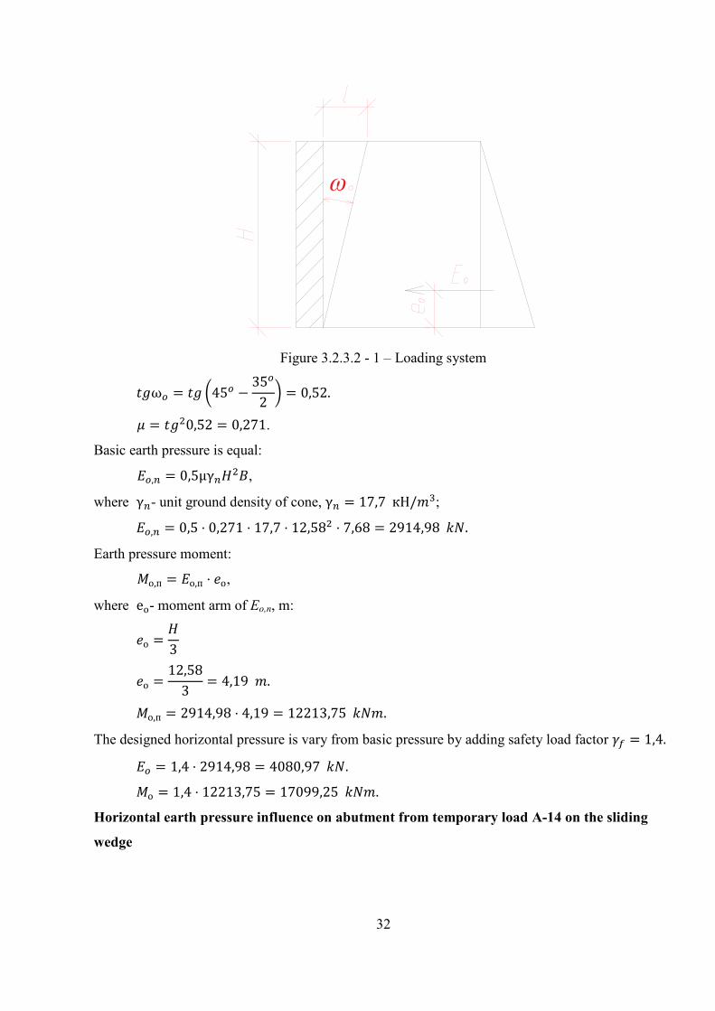
Horizontal earth pressure onto a abutment is defined using the scheme shown at figure 3.2.3.2. – 1.
pressure ratio is calculate by:
µ = 𝑡𝑔2ω𝑜,
where 𝑡𝑔ω𝑜 - dangerous slope of collapse to vertical:
𝑡𝑔ω𝑜 = 𝑡𝑔 �45𝑜 − φп2
�,
where φп - standard angle of internal friction, φп = 35𝑜;
32
Figure 3.2.3.2 - 1 – Loading system
𝑡𝑔ω𝑜 = 𝑡𝑔 �45𝑜 −35𝑜
2� = 0,52.
𝜇 = 𝑡𝑔20,52 = 0,271.
Basic earth pressure is equal:
𝐸𝑜,𝑛 = 0,5µγ𝑛𝐻2𝐵,
where γ𝑛- unit ground density of cone, γ𝑛 = 17,7 кН/𝑚3;
𝐸𝑜,𝑛 = 0,5 ⋅ 0,271 ⋅ 17,7 ⋅ 12,582 ⋅ 7,68 = 2914,98 𝑘𝑁.
Earth pressure moment:
𝑀о,п = 𝐸о,п ⋅ 𝑒о,
where ео- moment arm of Ео,п, m:
𝑒о =𝐻3
𝑒о =12,58
3= 4,19 𝑚.
𝑀о,п = 2914,98 ⋅ 4,19 = 12213,75 𝑘𝑁𝑚.
The designed horizontal pressure is vary from basic pressure by adding safety load factor 𝛾𝑓 = 1,4.
𝐸𝑜 = 1,4 ⋅ 2914,98 = 4080,97 𝑘𝑁.
𝑀о = 1,4 ⋅ 12213,75 = 17099,25 𝑘𝑁𝑚.
Horizontal earth pressure influence on abutment from temporary load A-14 on the sliding
wedge
33
Bridge and embankment are jointed with the help of subplate - length 8 m and width 10 m.
Temporary load located on the sliding wedge accepted by a half subplate length. Thus, all
dimensions of the temporary load distribution by the subplate amounts to: along superstructure
𝑏 = 0,5 ⋅ 8 = 4 𝑚; transversely superstructure 𝐵1 = 10 𝑚.
Part of the subplate length adjacent to the abutment and not participating in temporary load pressure
on the sliding wedge shall be noted: а = 8 – 4 = 4 m.
Before choosing the design model, first calculate the length of the sliding wedge:
𝑙𝑜 = 𝐻𝑡𝑔 �45 − φп2
�,
where H – height of embankment, H = 12,58 m;
𝑙𝑜 = 10,23 ⋅ 𝑡𝑔 �45 − 352
� = 5,33 𝑚.
Height of ground layer equivalent to two А–14 bogie’s axles pressure:
ℎ𝑜 = 2𝑃АтВ1𝑏γ𝑛
,
ℎ𝑜 = 2⋅28010⋅4⋅17,7
= 0,79 м.
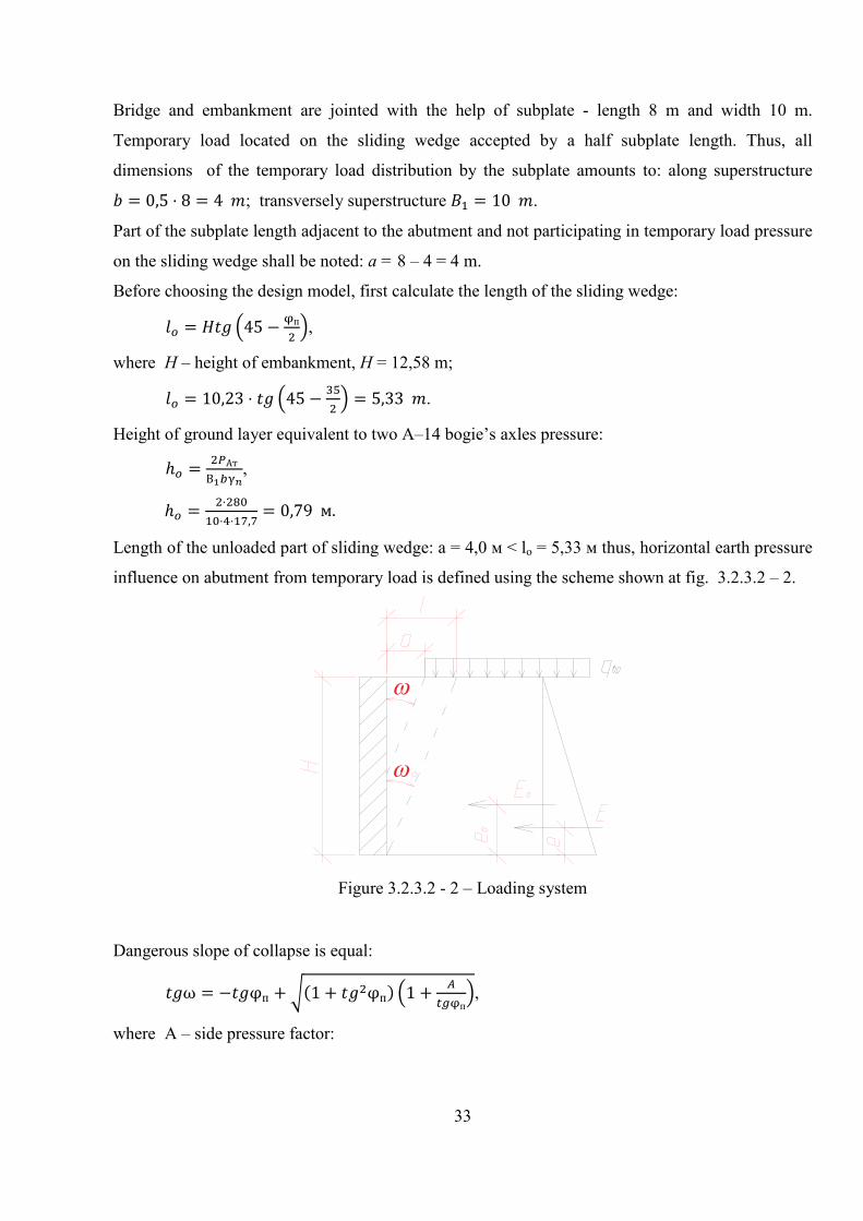
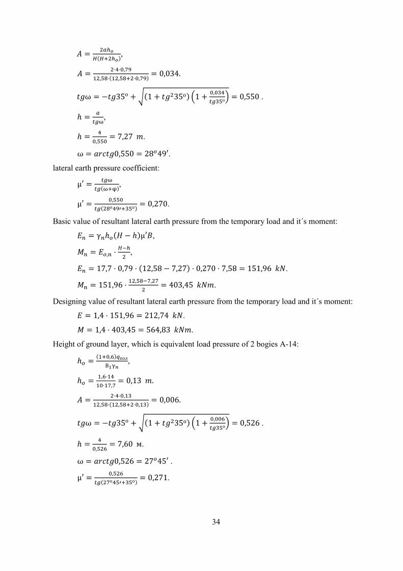
Length of the unloaded part of sliding wedge: а = 4,0 м < lо = 5,33 м thus, horizontal earth pressure
influence on abutment from temporary load is defined using the scheme shown at fig. 3.2.3.2 – 2.
Figure 3.2.3.2 - 2 – Loading system
Dangerous slope of collapse is equal:
𝑡𝑔ω = −𝑡𝑔φп + �(1 + 𝑡𝑔2φп) �1 + 𝐴𝑡𝑔φп
�,
where А – side pressure factor:
34
𝐴 = 2𝑎ℎ𝑜𝐻(𝐻+2ℎ𝑜),
𝐴 = 2⋅4⋅0,7912,58⋅(12,58+2⋅0,79) = 0,034.
𝑡𝑔ω = −𝑡𝑔35о + �(1 + 𝑡𝑔235о) �1 + 0,034𝑡𝑔35о� = 0,550 .
ℎ = 𝑎𝑡𝑔ω
,
ℎ = 40,550
= 7,27 𝑚.
ω = 𝑎𝑟𝑐𝑡𝑔0,550 = 28𝑜49′.
lateral earth pressure coefficient:
µ′ = 𝑡𝑔ω𝑡𝑔(ω+φ),
µ′ = 0,550𝑡𝑔(28о49′+35о) = 0,270.
Basic value of resultant lateral earth pressure from the temporary load and it´s moment:
𝐸𝑛 = γ𝑛ℎ𝑜(𝐻 − ℎ)µ′𝐵,
𝑀𝑛 = 𝐸𝑜,𝑛 ⋅ 𝐻−ℎ2
,
𝐸𝑛 = 17,7 ⋅ 0,79 ⋅ (12,58 − 7,27) ⋅ 0,270 ⋅ 7,58 = 151,96 𝑘𝑁.
𝑀𝑛 = 151,96 ⋅ 12,58−7,272
= 403,45 𝑘𝑁𝑚.
Designing value of resultant lateral earth pressure from the temporary load and it´s moment:
𝐸 = 1,4 ⋅ 151,96 = 212,74 𝑘𝑁.
𝑀 = 1,4 ⋅ 403,45 = 564,83 𝑘𝑁𝑚.
Height of ground layer, which is equivalent load pressure of 2 bogies A-14:
ℎ𝑜 = (1+0,6)𝑞полВ1γ𝑛
,
ℎ𝑜 = 1,6⋅1410⋅17,7
= 0,13 𝑚.
𝐴 = 2⋅4⋅0,1312,58⋅(12,58+2⋅0,13) = 0,006.
𝑡𝑔ω = −𝑡𝑔35о + �(1 + 𝑡𝑔235о) �1 + 0,006𝑡𝑔35о� = 0,526 .
ℎ = 40,526
= 7,60 м.
ω = 𝑎𝑟𝑐𝑡𝑔0,526 = 27𝑜45′ .
µ′ = 0,526𝑡𝑔(27о45′+35о) = 0,271.
35
Basic value of resultant lateral earth pressure from the temporary load and it´s moment:
𝐸𝑛 = 17,7 ⋅ 0,17 ⋅ (12,58 − 7,58) ⋅ 0,271 ⋅ 7,58 = 30,91 𝑘𝑁.
𝑀𝑛 = 30,91 ⋅ 12,58−7,582
= 77,28 𝑘𝑁𝑚.
Designing value of resultant lateral earth pressure from the temporary load and it´s moment:
𝐸 = 1,4 ⋅ 30,91 = 43,27 𝑘𝑁.
𝑀 = 1,4 ⋅ 77,28 = 108,19 𝑘𝑁𝑚.
Resultant action from bogie and lane load:
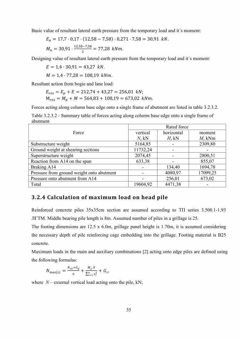
𝐸𝑟𝑒𝑠 = 𝐸𝑝 + 𝐸 = 212,74 + 43,27 = 256,01 𝑘𝑁;М𝑟𝑒𝑠 = 𝑀𝑝 + 𝑀 = 564,83 + 108,19 = 673,02 𝑘𝑁𝑚.
Forces acting along column base edge onto a single frame of abutment are listed in table 3.2.3.2. Table 3.2.3.2 - Summary table of forces acting along column base edge onto a single frame of abutment
Force Rated force
vertical N, kN
horizontal Н, kN
moment М, kNm
Substructure weight 5164,85 - 2309,80 Ground weight at shearing sections 11732,24 - - Superstructure weight 2074,45 - 2800,51 Reaction from А14 on the span 633,38 - 855,07 Braking А14 - 134,40 1694,78 Pressure from ground weight onto abutment - 4080,97 17099,25 Pressure onto abutment from A14 - 256,01 673,02 Total 19604,92 4471,38 - 3.2.4 Calculation of maximum load on head pile Reinforced concrete piles 35х35cm section are assumed according to ТП series 3.500.1-1.93
ЛГТМ. Middle bearing pile length is 8m. Assumed number of piles in a grillage is 25.
The footing dimensions are 12.5 х 6.0m, grillage panel height is 1.70m, it is assumed considering
the necessary depth of pile reinforcing cage embedding into the grillage. Footing material is В25
concrete.
Maximum loads in the main and auxiliary combinations [2] acting onto edge piles are defined using
the following formulas:
𝑁max(𝑥) =𝑁ох+𝐺р
𝑛+
𝑀𝑦⋅𝑋
∑ 𝑥𝑖2𝑛
𝑖=1+ 𝐺с,
where N – external vertical load acting onto the pile, kN;
36
n – number of piles, n = 25 pieces.;
My − moment from forces acting along the bridge at the footing lower part level, kN∙м;
X – coordinates of centers of the most distant piles from the footing axis in which forces are
the greatest, m;
Σ𝑖=1
𝑘𝑋𝑖
2 – sum of each pile coordinates second degrees, m;
Gр – footing weight, kN.
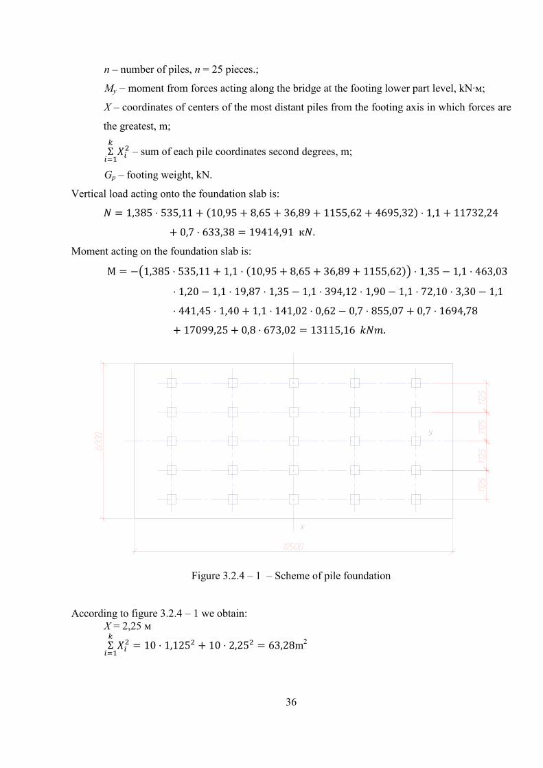
Vertical load acting onto the foundation slab is:
𝑁 = 1,385 ⋅ 535,11 + (10,95 + 8,65 + 36,89 + 1155,62 + 4695,32) ⋅ 1,1 + 11732,24
+ 0,7 ⋅ 633,38 = 19414,91 к𝑁.
Moment acting on the foundation slab is:
М = −�1,385 ⋅ 535,11 + 1,1 ⋅ (10,95 + 8,65 + 36,89 + 1155,62)� ⋅ 1,35 − 1,1 ⋅ 463,03
⋅ 1,20 − 1,1 ⋅ 19,87 ⋅ 1,35 − 1,1 ⋅ 394,12 ⋅ 1,90 − 1,1 ⋅ 72,10 ⋅ 3,30 − 1,1
⋅ 441,45 ⋅ 1,40 + 1,1 ⋅ 141,02 ⋅ 0,62 − 0,7 ⋅ 855,07 + 0,7 ⋅ 1694,78
+ 17099,25 + 0,8 ⋅ 673,02 = 13115,16 𝑘𝑁𝑚.
Figure 3.2.4 – 1 – Scheme of pile foundation
According to figure 3.2.4 – 1 we obtain: X = 2,25 м
Σ𝑖=1
𝑘𝑋𝑖
2 = 10 ⋅ 1,1252 + 10 ⋅ 2,252 = 63,28m2

37
Finally, maximum loads acting onto the endge piles are defined as follows:
𝑁max(𝑥) =19414,91
25+
13115,16 ⋅ 2,2563,28
= 1242,92 𝑘𝑁
38
3.3 Design of Intermediate Piers 3.3.1 General
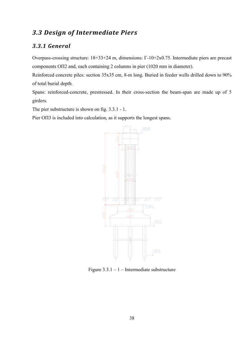
Overpass-crossing structure: 18+33+24 m, dimensions: Г-10+2х0.75. Intermediate piers are precast
components ОП2 and, each containing 2 columns in pier (1020 mm in diameter).
Reinforced concrete piles: section 35х35 cm, 8-m long. Buried in feeder wells drilled down to 90%
of total burial depth.
Spans: reinforced-concrete, prestressed. In their cross-section the beam-span are made up of 5
girders.
The pier substructure is shown on fig. 3.3.1 - 1.
Pier ОП3 is included into calculation, as it supports the longest spans.
Figure 3.3.1 – 1 – Intermediate substructure
39
3.3.2. Loads analysis In accordance with design project, the loads affecting on the front slope of the substructure ОП3’s
foundation will be analyzed in longitudinal and transverse directions of the bridge.
This calculation makes allowance for the following loads:
- permanent loads: induced by the proper weight of superstructures, substructure and the
foundation;
- temporary loads: vertical (induced by carrying equipment and pedestrian flow; horizontal
longitudinal (induced by braking action); horizontal transversal (induced by lateral impact).
- other loads: wind force.
3.3.2.1 Permanent loads The analysis of constant loads is to be carried out on the basis of half-spans (left and right from the
pier) with total length 332
+ 242
= 28.5 𝑚
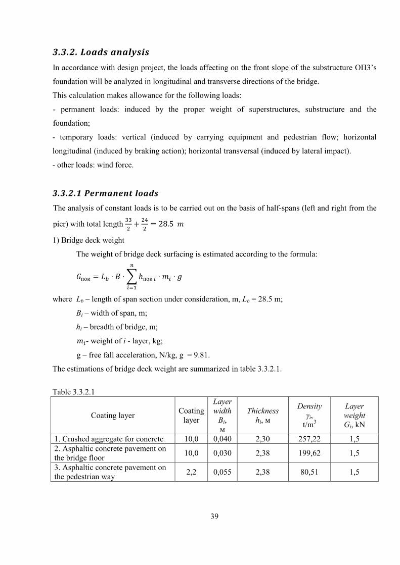
1) Bridge deck weight
The weight of bridge deck surfacing is estimated according to the formula:
𝐺пок = 𝐿𝑏 ⋅ 𝐵 ⋅ � ℎпок 𝑖 ⋅ 𝑚𝑖 ⋅ 𝑔𝑛
𝑖=1
where Lb – length of span section under consideration, m, Lb = 28.5 m;
Bi – width of span, m;
hi – breadth of bridge, m;
𝑚𝑖- weight of i - layer, kg;
g – free fall acceleration, N/kg, g = 9.81.
The estimations of bridge deck weight are summarized in table 3.3.2.1.
Table 3.3.2.1
Coating layer Coating layer
Layer width
Bi, м
Thickness hi, м
Density γi,
t/m3
Layer weight Gi, kN
1. Crushed aggregate for concrete 10,0 0,040 2,30 257,22 1,5 2. Asphaltic concrete pavement on the bridge floor 10,0 0,030 2,38 199,62 1,5
3. Asphaltic concrete pavement on the pedestrian way 2,2 0,055 2,38 80,51 1,5
40
4. Covering layer 12,28 0,060 2,20 453,20 1,3 5. Waterproofing 12,36 0,0055 1,50 28,51 1,3 6. Shaping course on the bridge floor 10,0 0,03 2,20 184,53 1,3
7. Shaping course on the pedestrian way 2,28 0,048 2,20 67,32 1,3
Total 1270,91 1,385
2) Weight of safety parapet, pedestrian railings and coping block
For the purposes of safe flow of traffic through the overpass-crossing, safety parapet 11МО-
0,75/1,5-190/0,48 has been installed. Its every running meter weighs mпог = 46.54 𝑘𝑔/𝑚.
The weight of safety parapet is calculated according to the formula:
𝐺БО = 2 ⋅ 𝐿b ⋅ mпог ⋅ 𝑔,
𝐺БО = 2 ⋅ 28,5 ⋅ 46,54 ⋅ 10−3 ⋅ 9,81 = 26,02 𝑘𝑁
To ensure pedestrian safety, the sidewalks are equipped with passenger railings and safety shields.
Each running meter of the passenger railing weighs mпо = 36,72 𝑘𝑔/𝑚. Each of the 14 safety
shields weights mпщ = 44.32 𝑘𝑔.
𝐺ПО = 2 ⋅ 𝐿b𝑙ПО
⋅ mПО ⋅ 𝑔 + mПЩ ⋅ nПЩ ⋅ 𝑔,
𝐺ПО = 2 ⋅ 28,5 ⋅ 36,72 ⋅ 10−3 ⋅ 9,81 + 44,32 ⋅ 10−3 ⋅ 14 ⋅ 9,81 = 26,62 𝑘𝑁.
The coping block is 𝑙К=2990 (≈3000) mm long and weighs mК=470.0 kg.
𝐺К = 2 ⋅ 𝐿b𝑙К
⋅ mК ⋅ 𝑔,
𝐺К = 2 ⋅285003000
⋅ 470,0 ⋅ 10−3 ⋅ 9,81 = 87,60 𝑘𝑁.
3) Weight of girders and monolithic sections
The pressure of the span is calculated according to the formula
𝐺БМ = (𝐺Б33+𝐺М33)+(𝐺Б24+𝐺М24)2
,
where GБ33, GБ24 – total weight of 33 and 24-m long span beams, kN;
𝐺Б33 = 𝑛б ⋅ 𝑚б33 ⋅ 𝑔,
where 𝑛б– number of girders in cross sectional area of the span, 𝑛б= 5;
𝑚б33 – girder weight, 𝑚б33= 54770 kg;
𝐺Б33 = 5 ⋅ 54770 ⋅ 10−3 ⋅ 9,81 = 2686,47 𝑘𝑁.
𝐺Б24 = 𝑛б ⋅ 𝑚б24 ⋅ 𝑔,
𝑚б24 – beam weight, 𝑚б24= 35730 kg.
41
𝐺Б24 = 5 ⋅ 35730 ⋅ 10−3 ⋅ 9,81 = 1752,56 𝑘𝑁.
GM33, GM24 - total weight of built-in monolithic supports, kN;
𝐺М33 = 𝐺МС33 + 𝐺МК33,
where GМС33, GМК33 – weight of edge and middle beams, respectively, kN.
𝐺МС33 = 𝑛𝑉МС33 ⋅ γжб,
where n – number of monolithic mid-beams, n = 4;
𝑉МС33- volume of monolithic mid-beams, m3, 𝑉МС33 = 5,94 m3;
γжб - specific weight of reinforced concrete, γжб = 2,5 t/m3.
𝐺МС33 = 4 ⋅ 5,94 ⋅ 2,5 ⋅ 9,81 = 582,71 kN;
𝐺МС24 = 4 ⋅ 4,32 ⋅ 2,5 ⋅ 9,81 = 423,79 kN;
𝐺МК33 = 𝑛𝑉МК33 ⋅ γжб,
where n – number of edge monolithic beam, n = 2;
𝑉МС33- volume of edge monolithic beam, 𝑉МК33 = 3,78 m3;
𝐺МК33 = 2 ⋅ 3,78 ⋅ 2,5 ⋅ 9,81 = 185,41 kN;
𝐺МК24 = 2 ⋅ 2,75 ⋅ 2,5 ⋅ 9,81 = 134,89 kN;
𝐺БМ =(2686,47 + 582,71 + 185,41) + (1752,56 + 423,79 + 134,89)
2= 2882,91 𝑘𝑁.
4) Weight of column cap with pedestals
Weight of column cap 𝐺Р, kN, to be calculated according to the formula
𝐺Р = 𝑉Р ⋅ γжб,
where Vp – column cap, Vp = 21.07 m3;
Gp = 21,07 ∙ 2,5 ∙ 9,81 = 516,74 kN.
Weight of pedestals 𝐺П, kN:
𝐺П = 𝑉п ⋅ γжб,
where VП – pedestals volume, VП = 2.62 m3;
𝐺П = 2,62 ⋅ 2,5 ⋅ 9,81 = 64,26 kN.
Weight of column cap’s de-watering 𝐺С, kN:
𝐺С = 𝑉с ⋅ γжб,
where Vс – de-watering volume, Vс = 0.54 m3;
𝐺П = 0,54 ⋅ 2,5 ⋅ 9,81 = 13,24 kN.
Total weight of column cap and pedestals 𝐺РП, kN:
42
𝐺РП = 516,74 + 64,26 +13,24 = 594,24 kN.
5) Weight of columns
𝐺𝑂 = 𝑉ж.б ⋅ 𝛾ж.б + 𝑉ст ⋅ 𝛾ст,
The pier pressure to the foundation:
where Vст – volume of the metal column from the edge of foundation down to the bottom of the
footing, Vст = 0.229 m3;
Vж.б. – the volume of concrete content in the columns from the edge of foundation down to
the bottom of the column cap, Vж.б = 14.26 m3;
γст - specific weight of steel, γст= 7.85 t/m3.
𝐺𝑂 = 14,26 ⋅ 2,5 ⋅ 9,81 + 2 ⋅ 0,229 ⋅ 7,85 ⋅ 9,81 = 385,0 𝑘𝑁/𝑚3.
3.3.2.2. Temporary loads 1) Imposed by А14 and crowd.
Standard vertical load imposed by pedestrian flow on sidewalks to be calculated according to the
formula:
𝑄л = 𝑞л ⋅ 𝐿𝑏 ⋅ 𝑇 ⋅ 𝑘,
where Т- width of sidewalk, Т = 0.75 m;
k – number of sidewalks, k = 2;
qл = 3.92 – 0.0196 . λ, kPa, but always higher than 1.96 kPa (paragraph.2.21 [1]);
λ – loading length, λ = 33 + 24 = 57 m.
qл = 3,92 - 0,0196 . 57 = 2,80 kPa;
Qл = 2,80 . 28,5 . 0,75 . 2 = 119,70 kN.
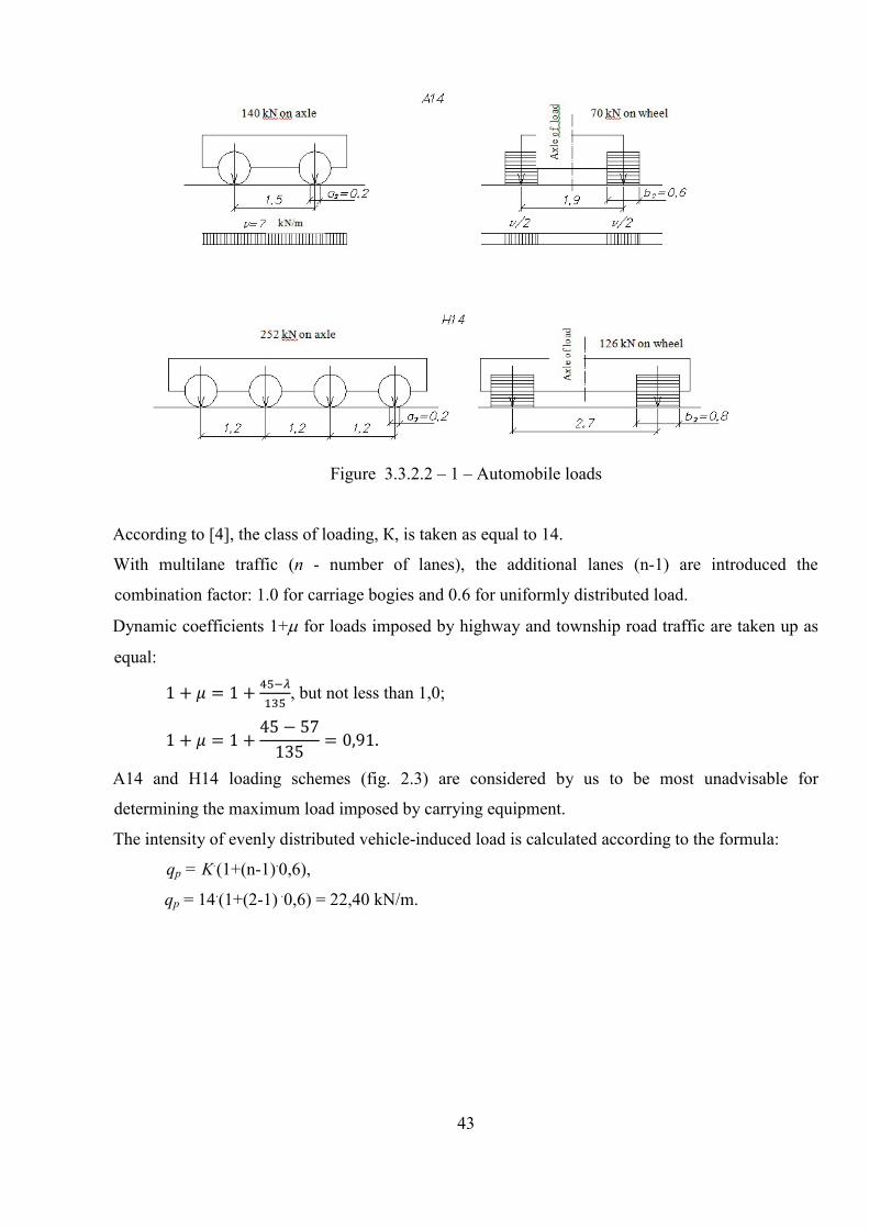
The standard temporary vertical load imposed by vehicles is defined as a number of lanes (fig.
3.3.2.2 - 1), each including one carriage bogie with axial stress Р equal to 10К kN (1К ton-force)
and uniformly distributed load with intensity ν = К kN/m (on both tracks).
43
Figure 3.3.2.2 – 1 – Automobile loads
According to [4], the class of loading, К, is taken as equal to 14.
With multilane traffic (n - number of lanes), the additional lanes (n-1) are introduced the
combination factor: 1.0 for carriage bogies and 0.6 for uniformly distributed load.
Dynamic coefficients 1+µ for loads imposed by highway and township road traffic are taken up as
equal:
1 + 𝜇 = 1 + 45−𝜆135
, but not less than 1,0;
1 + 𝜇 = 1 +45 − 57
135= 0,91.
А14 and Н14 loading schemes (fig. 2.3) are considered by us to be most unadvisable for
determining the maximum load imposed by carrying equipment.
The intensity of evenly distributed vehicle-induced load is calculated according to the formula:
qр = K.(1+(n-1).0,6),
qр = 14.(1+(2-1) .0,6) = 22,40 kN/m.
44
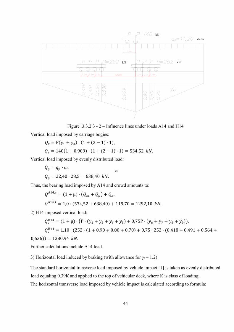
Figure 3.3.2.3 - 2 – Influence lines under loads A14 and H14
Vertical load imposed by carriage bogies:
𝑄т = Р(𝑦1 + 𝑦3) ⋅ (1 + (2 − 1) ⋅ 1),
𝑄т = 140(1 + 0,909) ⋅ (1 + (2 − 1) ⋅ 1) = 534,52 𝑘𝑁.
Vertical load imposed by evenly distributed load:
𝑄р = 𝑞𝑝 ⋅ ω,
𝑄р = 22,40 ⋅ 28,5 = 638,40 𝑘𝑁.
Thus, the bearing load imposed by А14 and crowd amounts to:
𝑄А14,т = (1 + µ) ⋅ �𝑄𝑚 + 𝑄𝑝� + 𝑄л,
𝑄А14,т = 1,0 ⋅ (534,52 + 638,40) + 119,70 = 1292,10 𝑘𝑁.
2) H14-imposed vertical load:
𝑄сН14 = (1 + µ) ⋅ �Р ⋅ (𝑦1 + 𝑦2 + 𝑦4 + 𝑦5) + 0,75Р ⋅ (𝑦6 + 𝑦7 + 𝑦8 + 𝑦9)�,
𝑄сН14 = 1,10 ⋅ (252 ⋅ (1 + 0,90 + 0,80 + 0,70) + 0,75 ⋅ 252 ⋅ (0,418 + 0,491 + 0,564 +
0,636)) = 1380,94 𝑘𝑁.
Further calculations include А14 load.
3) Horizontal load induced by braking (with allowance for γf = 1.2)
The standard horizontal transverse load imposed by vehicle impact [1] is taken as evenly distributed
load equaling 0.39К and applied to the top of vehicular deck, where К is class of loading.
The horizontal transverse load imposed by vehicle impact is calculated according to formula:
kN kN/m
kN
kN
kN
45
𝐻𝑦𝑚 = 0,39 ⋅ 𝐾 ⋅ (1 + (2 − 1) ⋅ 0,6) ⋅ 𝐿𝑏,
𝐻𝑦𝑚 = 0,39 ⋅ 14 ⋅ 28,5 = 155,61 kN.
The standard horizontal longitudinal load imposed by braking [1] is taken equaling 50% of the
transport-imposed evenly distributed part of load Н14 (the weight of carriage bogies is not
considered in the loadings) and is never less than 7.8К (109.2 kN) or over 24.5К (343.0 kN):
Нхт = 0,5.Qр ,
Нхт = 0,5 . 22,40 . 28,5 = 319,20 kN.
Further estimation, thus, includes the horizontal longitudinal load imposed by braking and equaling
319.20 kN.
3.3.3. Other loads 1) Wind load
In cross direction, the wind load is estimated according to the formula:
𝐻𝑦в = ∑ 𝑊𝑛𝑆𝑦𝑖,
Lengthwise, the wind load is calculated according to the formula:
𝐻𝑥в = ∑ 𝑊𝑛𝑆𝑥𝑖,
The regulatory value of wind load Wn is to be estimated as sum total of the standard values of mean
Wm and oscillatory Wp components:
𝑊𝑛 = 𝑊𝑚 + 𝑊𝑝,
The standard value of the mean wind load Wm at height z over water of ground surface is calculated
according to the formula:
𝑊𝑚 = 𝑊𝑜 ⋅ 𝑘 ⋅ 𝐶𝑤,
where Wo – standard value of wind pressure, [2] (Mirny town is situated in the first wind area Wo =
0.7 kPa);
k – coefficient, used to make allowance for the change in wind pressure throughout height z,
[2], k = 0.60;
Cw – aerodynamic coefficient for frontal resistance of the bridge structure, is specified in
annex 9 [1]. Equals 1.7 for road bridges with plain-girder spans, 1.8 for piers, 2.1 for
pedestals and column cap and 1.4 for pedestrian railing and safety shields.
The standard value of oscillatory component of wind load Wp at height z:
𝑊𝑝 = 𝑊𝑚 ⋅ ξ ⋅ 𝐿 ⋅ 𝑣,
46
where ξ — dynamic amplification factor;
L — pulsation factor of wind pressure at level z;
v —spatial correlation coefficient for pressure pulsations of the construction’s reference
surface.
The estimation of the wind load oscillation applicable to bridge structures can be based on the
following assumptions:
а) the product of coefficients Lv to be regarded as equaling:
0.55 — 0.15 λ/100, but always higher than 0.30;
where: λ — span length or pier height, m.
- span: Lv= 0,55 - 0,15 . 28,5/100 = 0,51< 0,3 (assume Lv = 0,51);
- pier: Lv= 0,55 - 0,15 . 8,60/100 = 0,54< 0,3 (assume Lv = 0,54);
б) dynamic amplification factor for beam spans to be regarded as equaling 1.2. The wind load calculations are summarized in Table 3.3.3. For span, pedestrian railing and safety shields, the standard horizontal longitudinal load is regarded as accounting for 20% of the total standard transverse wind load. Table 3.3.3 - Wind load
Structural component Wm,
kPa
Wp,
kPa
Wn,
kPa
Syi,
m2
Sxi,
m2
𝐻𝑦в,
kN
𝐻𝑥в,
kN
Span 0.17 0.10 0.59 47.70 - 28.14 5.63 Pier cap 0.21 0.13 0.59 1.66 13.17 0.98 7.77 Bridge pads 0.21 0.13 0.59 0.64 2.48 0.38 1.46 Pier 0.18 0.12 0.59 8.77 17.54 5.17 10.34 Pedestrian railing and safety shields
0.14 0.09 0.59 51.37 - 30.31 6.06
Total 64.98 31.26
3.3.4 Factors of safety The formula for estimating permanent structural design loads (main load combinations) includes
the partial safety factor for loads γf equaling 1.1, except for road surface weight whose γf equals
1.385 [1].
The formula for estimating all permanent structural design loads (with additional load
combinations) includes the partial safety factor for load γf equaling 0.9.
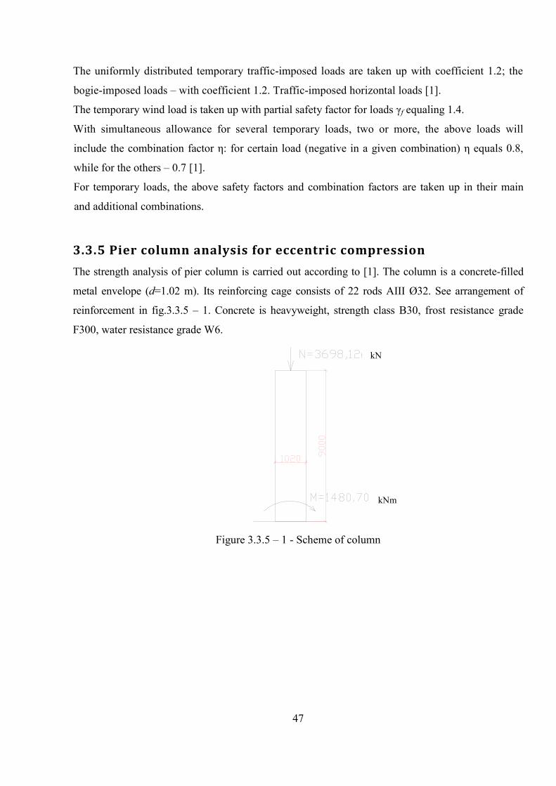
47
The uniformly distributed temporary traffic-imposed loads are taken up with coefficient 1.2; the
bogie-imposed loads – with coefficient 1.2. Traffic-imposed horizontal loads [1].
The temporary wind load is taken up with partial safety factor for loads γf equaling 1.4.
With simultaneous allowance for several temporary loads, two or more, the above loads will
include the combination factor η: for certain load (negative in a given combination) η equals 0.8,
while for the others – 0.7 [1].
For temporary loads, the above safety factors and combination factors are taken up in their main
and additional combinations.
3.3.5 Pier column analysis for eccentric compression The strength analysis of pier column is carried out according to [1]. The column is a concrete-filled
metal envelope (d=1.02 m). Its reinforcing cage consists of 22 rods AIII Ø32. See arrangement of
reinforcement in fig.3.3.5 – 1. Concrete is heavyweight, strength class В30, frost resistance grade
F300, water resistance grade W6.
Figure 3.3.5 – 1 - Scheme of column
kN
kNm
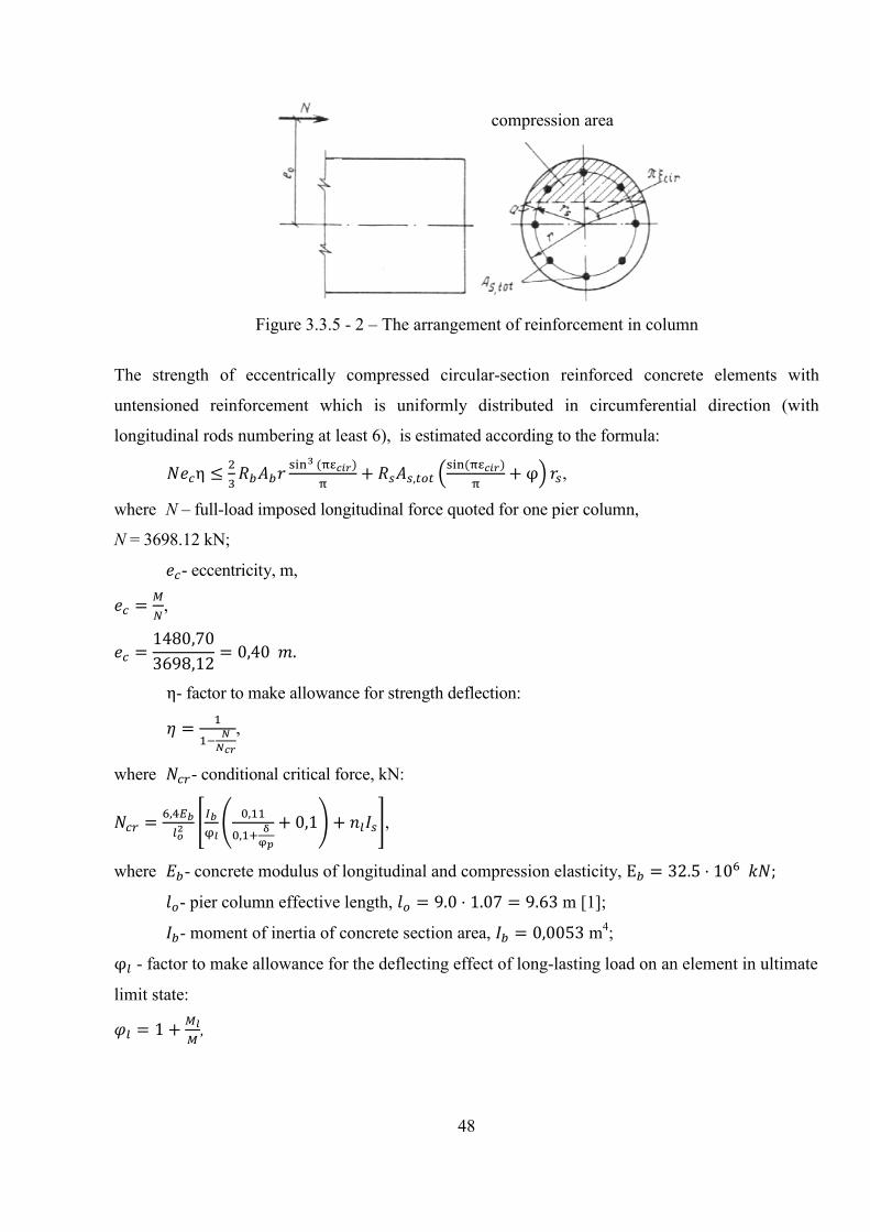
48
Figure 3.3.5 - 2 – The arrangement of reinforcement in column
The strength of eccentrically compressed circular-section reinforced concrete elements with
untensioned reinforcement which is uniformly distributed in circumferential direction (with
longitudinal rods numbering at least 6), is estimated according to the formula:
𝑁𝑒𝑐η ≤ 23
𝑅𝑏𝐴𝑏𝑟 sin 3 (πε𝑐𝑖𝑟)π
+ 𝑅𝑠𝐴𝑠,𝑡𝑜𝑡 �sin(πε𝑐𝑖𝑟)π
+ φ� 𝑟𝑠,
where N – full-load imposed longitudinal force quoted for one pier column,
N = 3698.12 kN;
𝑒𝑐- eccentricity, m,
𝑒𝑐 = 𝑀𝑁
,
𝑒𝑐 =1480,703698,12
= 0,40 𝑚.
η- factor to make allowance for strength deflection:
𝜂 = 1
1− 𝑁𝑁𝑐𝑟
,
where 𝑁𝑐𝑟- conditional critical force, kN:
𝑁𝑐𝑟 = 6,4𝐸𝑏𝑙𝑜
2 �𝐼𝑏φ𝑙
� 0,11
0,1+ δφ𝑝
+ 0,1� + 𝑛𝑙𝐼𝑠�,
where 𝐸𝑏- concrete modulus of longitudinal and compression elasticity, Е𝑏 = 32.5 ⋅ 106 𝑘𝑁;
𝑙𝑜- pier column effective length, 𝑙𝑜 = 9.0 ⋅ 1.07 = 9.63 m [1];
𝐼𝑏- moment of inertia of concrete section area, 𝐼𝑏 = 0,0053 m4;
φ𝑙 - factor to make allowance for the deflecting effect of long-lasting load on an element in ultimate
limit state:
𝜑𝑙 = 1 + 𝑀𝑙𝑀
,
compression area
49
where 𝑀𝑙 - moment with respect to tensile or least compressed cross section face affected by constant
loads, 𝑀𝑙 = 3077.66 ⋅ 0.444 = 1366,48 kNm;
𝑀 - moment with respect to tensile or least compressed cross section face affected by constant
and temporary loads, 𝑀 = 3698,12 ⋅ 0,444 = 1641,97 kNm;
𝜑𝑙 = 1 +1366,481641,97
= 1,832.
δ- factor taken up as equaling:
𝛿 = 𝑒𝑐𝐷
,
where d – pier column diameter, d = 1.02 m;
𝛿 =0,401,02
= 0,392.
φр- factor to make allowance for the influence of prestressed reinforcement on stiffness of the
element, φр = 1;
𝑛𝑙 - concrete-to-reinforcement modulus elasticity ratio:
𝑛𝑙 = Е𝑠𝐸𝑏
,
where 𝐸𝑠- concrete modulus of elasticity, Е𝑠 = 1,96 ⋅ 108 kPa;
𝑛𝑙 =1,96 ⋅ 108
32,5 ⋅ 106 = 6,031.
𝐼𝑠- moment of inertia of untensioned reinforcement area, 𝐼𝑠 = 1,74 ⋅ 10−3 m4.
𝑁𝑐𝑟 =6,4 ⋅ 32,5 ⋅ 106
9,632 �0,0531,832
�0,11
0,1 + 0,401
+ 0,1� + 6,031 ⋅ 1,74 ⋅ 10−3� = 44612,01 𝑘𝑁.
η =1
1 − 3698,1244612,01
= 1,09.
𝑅𝑏- design strength of concrete В30, 𝑅𝑏 = 15,5 ⋅ 103 kPa;
𝐴𝑏- concrete area, 𝐴𝑏 = 0,817 m²;
r – pier column cross-section radius, r = 0.51 m;
𝑅𝑠- design resistance of AIII reinforcement to tensioning, 𝑅𝑠 = 350,0 ⋅ 103 kPa;
𝐴𝑠,𝑡𝑜𝑡 −area of longitudinal reinforcement, As,tot = 0,0177 m2;
𝑟𝑠- circle radius passing through the gravitational centers of longitudinal reinforcing rods, 𝑟𝑠 = 0,444
m;
50
ε𝑐𝑖𝑟- relative area of compressive zone of the concrete, which is determined by solution of equation:
ε𝑐𝑖𝑟 =𝑁 + 𝑅𝑠𝐴𝑠,𝑡𝑜𝑡 + 𝑅𝑏𝐴𝑏 ⋅ sin(2πε𝑐𝑖𝑟)
2π𝑅𝑏𝐴𝑏 + 2,55𝑅𝑠𝐴𝑠,𝑡𝑜𝑡
ε𝑐𝑖𝑟 =3698,12 + 350,0 ⋅ 103 ⋅ 0,0177 + 15,5 ⋅ 103 ⋅ 0,817 ⋅ sin(2π ⋅ ε𝑐𝑖𝑟)
2π15,5 ⋅ 103 ⋅ 0,817 + 2,55 ⋅ 350,0 ⋅ 103 ⋅ 0,0177
= 0,392
.
𝜑 - factor to make allowance for the work of tensile reinforcement, equals:
𝜑 = 1,6(1 − 1,55ε𝑐𝑖𝑟)ε𝑐𝑖𝑟,
𝜑 = 1,6(1 − 1,55 ⋅ 0,392)0,392 = 0,246.
3698,12 ⋅ 0,40 ⋅ 1,09 ≤23
⋅ 15,5 ⋅ 103 ⋅ 0,817 ⋅ 0,510sin 3 (π ⋅ 0,392)
π+
+350,0 ⋅ 103 ⋅ 0,0177 × �sin(π ⋅ 0,392)
π+ 0,246� ⋅ 0,444;
1614,56 kNm < 2651,43 kNm.
Strength condition has been observed.
3.3.6 Column cap analysis
Design constant load on column cap
The design constant load on column cap is made up of:
− six constant concentrated forces 𝑄П, kN, transferred through bridge seats which sustain the weight
of span, deck, pedestrian railings and pedestals:
𝑄П = 5149,115
= 1029,82 kN.
− uniformly distributed sole weight of column cap qр, kN/m
𝑞𝑝 = 𝐺𝑝
𝑙,
where 𝐺Р − weight of column cap, kN, 𝐺Р = 282.15;
𝑙 − length column cap, m, 𝑙= 13.54;
𝑞р = 582,9813,54
= 43,06 kN/m.
51
Design permanent load on column cap
The temporary loads on the bridge road include:
1) А14 bogie-imposed load with allowance for dynamic coefficient 1+µ=1.0 and partial safety
factor for loads 1.2;
𝑄А14Т = 1,0 ⋅ 10 ⋅ 14(1 + 0,909) ⋅ 1,2 = 320,71 kN.
2) А14 distributed loading with allowance for dynamic coefficient 1.0 and partial safety factor for
loads 1.2;
𝑄А14Р = 1,0 ⋅ 14 ⋅ 28,5 ⋅ 1,2 = 478,80 kN.
3) load induced by heavy isolated vehicular load Н14 with allowance for dynamic coefficient 1.1
and partial safety factor for loads 1.0;
𝑄Н14 = 1380,94 kN.
4) load induced by pedestrian flow passing along the sidewalk with allowance for partial safety
factor for loads 1.2.
Qл= 2,80∙28,5∙0,75∙1,2 = 71,82 kN.
Depending on the position of the temporary load on the bridge road, the force transferable to the
footing from every beam will vary. The footing should be analyzed at maximum transverse forces
occurring in the girders. To determine the unfavorable position of temporary load, it is necessary to
draw the influence lines of support resistance and define their values in each position of the
temporary load.
Since span is symmetric, the influence lines need to be drawn for the first three beams only. Where
moments of inertia are equal for all the beams, the ordinates of influence lines will be calculated
according to the following formulae (eccentric compression): (a) for marginal beam and (b) for
middle beams.
𝑦1 = 1𝑛
+ 𝑎12
2 ∑ 𝑎𝑖2 и 𝑦1
/ = 1𝑛
− 𝑎12
2 ∑ 𝑎𝑖2; (a)
𝑦1 = 1𝑛
+ 𝑎𝑖⋅𝑎12 ∑ 𝑎𝑖
2 и 𝑦1/ = 1
𝑛− 𝑎𝑖⋅𝑎1
2 ∑ 𝑎𝑖2, (b)
where n – number of beams;
ai – distance between axes of couples of symmetric beams.
Formulas (a) and (b):
- edge beam (fig. 3.3.6 - 1):
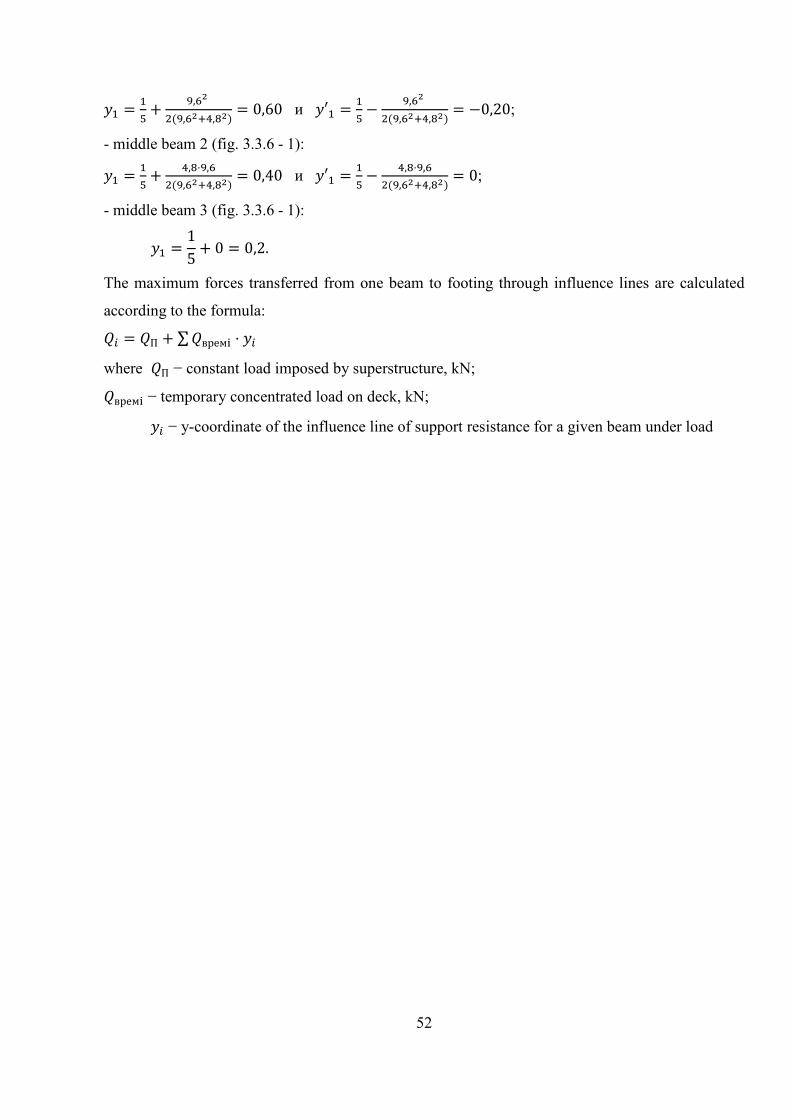
52
𝑦1 = 15
+ 9,62
2(9,62+4,82)= 0,60 и 𝑦′1 = 1
5− 9,62
2(9,62+4,82)= −0,20;
- middle beam 2 (fig. 3.3.6 - 1):
𝑦1 = 15
+ 4,8⋅9,62(9,62+4,82)
= 0,40 и 𝑦′1 = 15
− 4,8⋅9,62(9,62+4,82)
= 0;
- middle beam 3 (fig. 3.3.6 - 1):
𝑦1 =15
+ 0 = 0,2.
The maximum forces transferred from one beam to footing through influence lines are calculated
according to the formula:
𝑄𝑖 = 𝑄П + ∑ 𝑄времi ⋅ 𝑦𝑖
where 𝑄П − constant load imposed by superstructure, kN;
𝑄времi − temporary concentrated load on deck, kN;
𝑦𝑖 − y-coordinate of the influence line of support resistance for a given beam under load
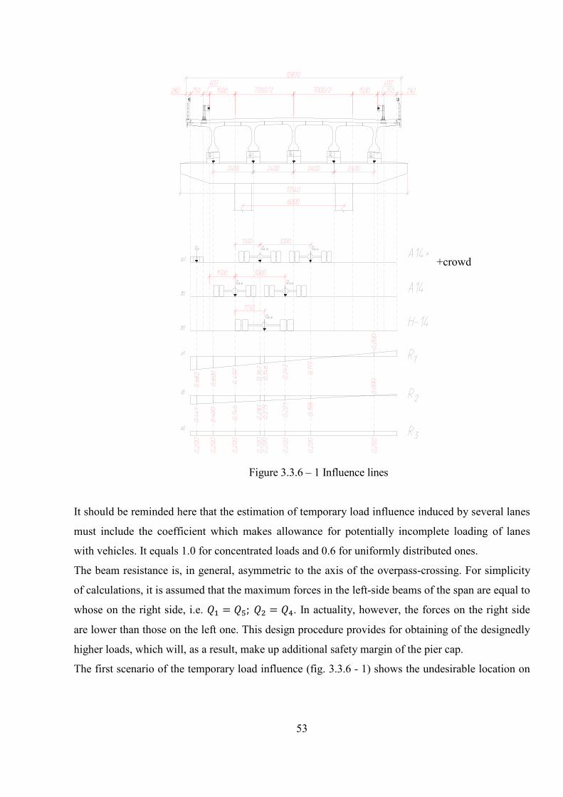
53
Figure 3.3.6 – 1 Influence lines
It should be reminded here that the estimation of temporary load influence induced by several lanes
must include the coefficient which makes allowance for potentially incomplete loading of lanes
with vehicles. It equals 1.0 for concentrated loads and 0.6 for uniformly distributed ones.
The beam resistance is, in general, asymmetric to the axis of the overpass-crossing. For simplicity
of calculations, it is assumed that the maximum forces in the left-side beams of the span are equal to
whose on the right side, i.e. 𝑄1 = 𝑄5; 𝑄2 = 𝑄4. In actuality, however, the forces on the right side
are lower than those on the left one. This design procedure provides for obtaining of the designedly
higher loads, which will, as a result, make up additional safety margin of the pier cap.
The first scenario of the temporary load influence (fig. 3.3.6 - 1) shows the undesirable location on
+crowd
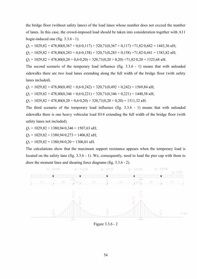
54
the bridge floor (without safety lanes) of the load lanes whose number does not exceed the number
of lanes. In this case, the crowd-imposed load should be taken into consideration together with А11
bogie-induced one (fig. 3.3.6 - 1).
Q1 = 1029,82 + 478,80(0,367 + 0,6∙0,117) + 320,71(0,367 + 0,117) +71,82∙0,682 = 1443,36 кН;
Q2 = 1029,82 + 478,80(0,283 + 0,6∙0,158) + 320,71(0,283 + 0,158) +71,82∙0,441 = 1383,82 кН;
Q3 = 1029,82 + 478,80(0,20 + 0,6∙0,20) + 320,71(0,20 + 0,20) +71,82∙0,20 = 1325,68 кН.
The second scenario of the temporary load influence (fig. 3.3.6 - 1) means that with unloaded
sidewalks there are two load lanes extending along the full width of the bridge floor (with safety
lanes included).
Q1 = 1029,82 + 478,80(0,492 + 0,6∙0,242) + 320,71(0,492 + 0,242) = 1569,84 кН;
Q2 = 1029,82 + 478,80(0,346 + 0,6∙0,221) + 320,71(0,346 + 0,221) = 1440,58 кН;
Q3 = 1029,82 + 478,80(0,20 + 0,6∙0,20) + 320,71(0,20 + 0,20) = 1311,32 кН.
The third scenario of the temporary load influence (fig. 3.3.6 - 1) means that with unloaded
sidewalks there is one heavy vehicular load Н14 extending the full width of the bridge floor (with
safety lanes not included).
Q1 = 1029,82 + 1380,94∙0,346 = 1507,63 кН;
Q2 = 1029,82 + 1380,94∙0,273 = 1406,82 кН;
Q3 = 1029,82 + 1380,94∙0,20 = 1306,01 кН.
The calculations show that the maximum support resistance appears when the temporary load is
located on the safety lane (fig. 3.3.6 - 1). We, consequently, need to load the pier cap with them to
draw the moment lines and shearing force diagrams (fig. 3.3.6 - 2).
Figure 3.3.6 - 2
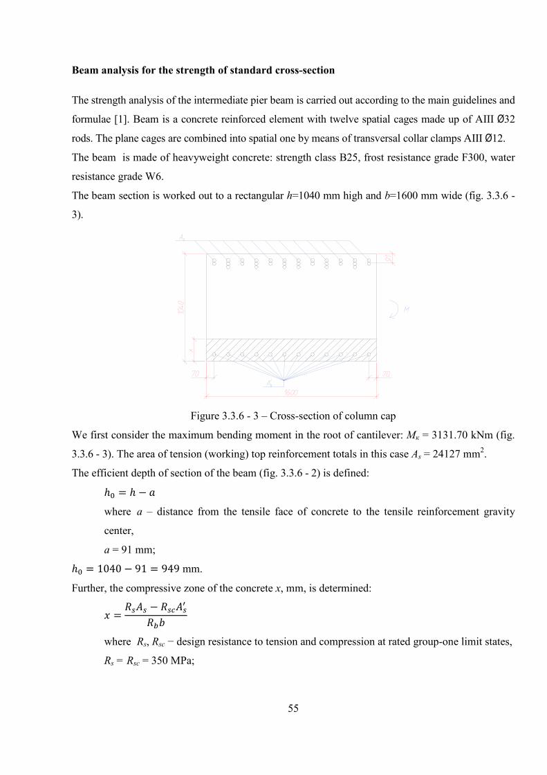
55
Beam analysis for the strength of standard cross-section
The strength analysis of the intermediate pier beam is carried out according to the main guidelines and
formulae [1]. Beam is a concrete reinforced element with twelve spatial cages made up of AIII Ø32
rods. The plane cages are combined into spatial one by means of transversal collar clamps AIII Ø12.
The beam is made of heavyweight concrete: strength class В25, frost resistance grade F300, water
resistance grade W6.
The beam section is worked out to a rectangular h=1040 mm high and b=1600 mm wide (fig. 3.3.6 -
3).
Figure 3.3.6 - 3 – Cross-section of column cap
We first consider the maximum bending moment in the root of cantilever: Мк = 3131.70 kNm (fig.
3.3.6 - 3). The area of tension (working) top reinforcement totals in this case Аs = 24127 mm2.
The efficient depth of section of the beam (fig. 3.3.6 - 2) is defined:
ℎ0 = ℎ − 𝑎
where а – distance from the tensile face of concrete to the tensile reinforcement gravity
center,
а = 91 mm;
ℎ0 = 1040 − 91 = 949 mm.
Further, the compressive zone of the concrete х, mm, is determined:
𝑥 =𝑅𝑠𝐴𝑠 − 𝑅𝑠𝑐𝐴𝑠
′
𝑅𝑏𝑏
where Rs, Rsс − design resistance to tension and compression at rated group-one limit states,
Rs = Rsс = 350 МPа;
56
Аs, А’s − area of tensile and compressive reinforcement, respectively,
𝐴𝑠 = 24127 𝑚𝑚2; 𝐴′𝑠 = 9651 𝑚𝑚2;
𝑥 = 350⋅24127−350⋅965113⋅1600
= 244 mm.
The relative height of compressive zone of the concrete equals:
ξу =0,85 − 0,008𝑅𝑏
1 + 𝑅𝑠500 �1 − 0,85 − 0,008𝑅𝑏
1,1 �
where Rb − design resistance to compression of the concrete В25, Rb = 13.0 MPa.
ξу =0,85 − 0,008 ⋅ 13
1 + 350500 �1 − 0,85 − 0,008 ⋅ 13
1,1 �= 0,609
As х = 244 mm < ξуh0 = 0.609·949 = 577 mm, the strength of the section is determined on the
following basis:
𝑀 ≤ 𝑅𝑏𝑏𝑥 (ℎ0 − 0,5𝑥) + 𝑅𝑠𝑐𝐴𝑠′ (ℎ0 − 𝑎𝑠′),
where а′𝑠 – distance from the compressed face of the concrete to compressive
reinforcement gravity center, а = 67 mm;
3131,70 kNm < 13∙1600∙244(949 – 0,5∙244) + 350∙9651(949 − 67) =
= 7170,49∙106 N∙mm = 7170,49 kNm.
Thus, the strength of standard cross-section of the beam in the root of cantilever is ensured.
Since in the middle of the span, as well as in the root of cantilever, it is the top of the column cap
that is subjected to tensioning, the reinforcement is not analyzed for tension force.
Beam analysis for cracking resistance
The analysis is made for rated forces, with dynamic coefficient not included. The analysis of
concrete elements reinforced with standard lattice rods for cracking resistance boils down to
determining the cracks opening width in the tension area and restricting their values.
The analysis targets the root of cantilever of the footing, where maximum moment Мк = 3131.70
kNm occurs. According to [1], the opening width of cracks, normal and inclined to longitudinal
axis, аcr, cm, in the concrete elements designed in accordance with cracking resistance requirements
2b, 3a, 3b and 3c, is calculated according to the formula
𝑎𝑐𝑟 =σ𝐸
ψ ≤ Δ𝑐𝑟
57
where σ − tensile stress, equaling for untensioned reinforcement to the tension σs in the
most strained (end) bars, MPa,;
Е − elasticity modulus for untensioned Es reinforcement of Е = 1.96.105 MPa;
ψ − crack opening coefficient determined on the basis of the reinforcement radius (it takes into
account the tensile zone of the concrete, deformation and profile of reinforcement, operating
conditions of the element); taken up according to [1].
∆сr − limit value of the estimated crack opening width, cm, which is taken up according to [1] for
cracking resistance category 3c ∆сr = 0.03 cm.
Tensile stress to be calculated according to the formula:
σ = 𝑅𝑠𝑀
𝑀𝑢,
where Ми − limit strength moment equaling to the right part of in equation
σ = 350 3131,707170,49
= 152,86 МPа.
ψ = 1,5�𝑅𝑟,
where 𝑅𝑟 − reinforcement radius Rr, cm, a design characteristic of concrete cross-section,
which defines the distance between cracks and calculated according to the formula
𝑅𝑟 = 𝐴𝑟Σβ𝑛𝑑
,
where Ar − square interaction zone area for standard cross-section, taken as restricted by the
outer contour of the section and instantaneous radius r = 6d, сm²;
β − coefficient to make allowance for concrete-to-steel bond degree according to [1],
β = 0.80;
n − number of reinforcement elements of equal nominal diameter d, n = 30;
d − rod diameter, d = 3.2 cm.
𝑅𝑟 = (6⋅3,2+14,7)⋅160,00,80⋅30⋅3,2
= 70,6 cm
ψ = 1,5√70,6 = 12,61.
Consequently, the width of crack openings in the root cantilever of the beam equals:
𝑎𝑐𝑟 = 152,861,96⋅105 ⋅ 12,61 = 0,010 < Δ𝑐𝑟 = 0,03 cm.
The cracking resistance of the beam section in the root of cantilever is thus ensured.
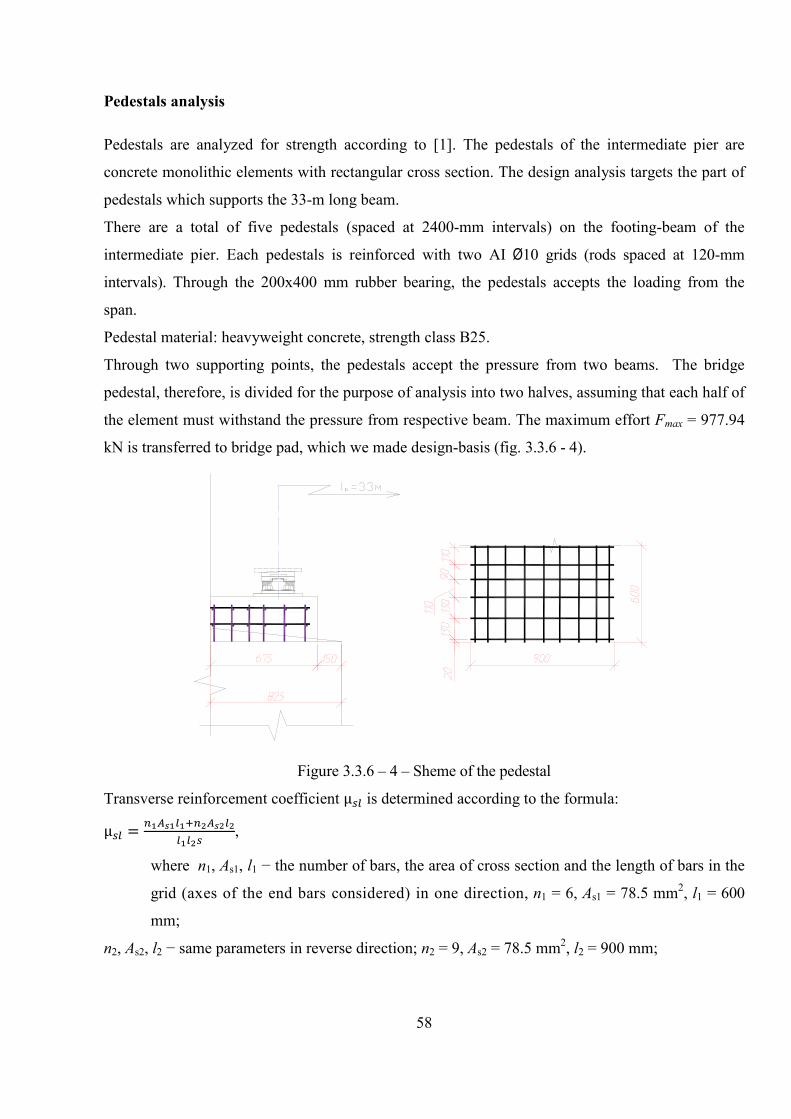
58
Pedestals analysis
Pedestals are analyzed for strength according to [1]. The pedestals of the intermediate pier are
concrete monolithic elements with rectangular cross section. The design analysis targets the part of
pedestals which supports the 33-m long beam.
There are a total of five pedestals (spaced at 2400-mm intervals) on the footing-beam of the
intermediate pier. Each pedestals is reinforced with two AI Ø10 grids (rods spaced at 120-mm
intervals). Through the 200х400 mm rubber bearing, the pedestals accepts the loading from the
span.
Pedestal material: heavyweight concrete, strength class В25.
Through two supporting points, the pedestals accept the pressure from two beams. The bridge
pedestal, therefore, is divided for the purpose of analysis into two halves, assuming that each half of
the element must withstand the pressure from respective beam. The maximum effort Fmax = 977.94
kN is transferred to bridge pad, which we made design-basis (fig. 3.3.6 - 4).
Figure 3.3.6 – 4 – Sheme of the pedestal
Transverse reinforcement coefficient µ𝑠𝑙 is determined according to the formula:
µ𝑠𝑙 = 𝑛1𝐴𝑠1𝑙1+𝑛2𝐴𝑠2𝑙2𝑙1𝑙2𝑠
,
where n1, As1, l1 − the number of bars, the area of cross section and the length of bars in the
grid (axes of the end bars considered) in one direction, n1 = 6, As1 = 78.5 mm2, l1 = 600
mm;
n2, As2, l2 − same parameters in reverse direction; n2 = 9, As2 = 78.5 mm2, l2 = 900 mm;
59
s − step of grid, s = 120 mm;
µ𝑠𝑙 = 6⋅78,5⋅600+9⋅78,5⋅900600⋅900⋅120
= 0,014.
The factors ап and k, which are used to define the reduced В25 concrete prism strength, are
estimated according to the formulas:
𝑎𝑛 = µ𝑠𝑙𝑅𝑠𝑅𝑏
,
𝑎𝑛 = 0,014⋅21013
= 0,226.
𝑘 = 5+𝑎𝑛1+4,5𝑎𝑛
,
𝑘 = 5+0,2261+4,5⋅0,226
= 2,591.
The bearing surface Aloc, mm2, is equal to the area of rubber bearing, which communicates the
loading from the beam to the pedestal, and amounts to
Aloc = 200 ∙ 400 = 8,0 ∙ 104 mm2.
The content of concrete inside the reinforcement contour Аd, mm2, equals
Аd = 900 ∙ 600 = 5,4 ∙ 105 mm2.
The reference area Аpl, mm2, equals the area of pedestal
Аpl = 1000 ∙ 650 = 6,5 ∙ 105 mm2.
The area Аpl must not exceed 1.25
Aloc = 1.25 ∙ 8.0 ∙ 104 = 10.0 ∙ 104 mm2.
mloc and ms factors are estimated according to the formulas
𝑚𝑙𝑜𝑐 = �𝐴𝑝𝑙
𝐴𝑙𝑜𝑐≤ 33 ,
𝑚𝑙𝑜𝑐 = �10,0⋅104
8,0⋅104
3= 1,08.
𝑚𝑠 = 4,5 − 3,5 𝐴𝑙𝑜𝑐𝐴𝑑
,
𝑚𝑠 = 4,5 − 3,5 8,0⋅104
5,4⋅105 = 3,98.
The reduced concrete prism strength Rb,red, МPa, is calculated according to the formula
𝑅𝑏,𝑟𝑒𝑑 = 𝑅𝑏𝑚𝑙𝑜𝑐 + 𝑘µ𝑠𝑙𝑚𝑠𝑅𝑠,
𝑅𝑏,𝑟𝑒𝑑 = 13 ⋅ 1,08 + 2,591 ⋅ 0,014 ⋅ 3,98 ⋅ 210 = 44,36 МPа.
Pedestal strength condition
𝐹max ≤ 𝑅𝑏,𝑟𝑒𝑑𝐴𝑙𝑜𝑐,
60
977,74 𝑘𝑁 < 44,36 ⋅ 8,0 ⋅ 104 = 3548,80 ⋅ 103N =3548,80 kN.
The pedestal strength is ensured.
Pile foundation analysis
The reinforced-concrete piles with 35х35 cm section are defined according to technical design
3.500.1-1.93 ЛГТМ. The piles of the intermediate piers are 8 m long. The foundation frame is
assumed to have 21 piles.
The assumed dimensions of the foundation are 10.0 х 4.0 m, pile interval being 1.4 m. The
foundation mat is 2.0 m high and is assumed with account of required depth of the pile’s
reinforcement cage embedding in the foundation frame. The foundation frame is made of В25
concrete.
The estimation is to be carried out according to [3].
The highest loads in main and additional combinations, which fall on edge piles, are estimated
according to the following formulas:
𝑁max(𝑥) =𝑁ох+𝐺р
𝑛+
𝑀𝑦⋅𝑋
∑ 𝑥𝑖2𝑛
𝑖=1,
𝑁max(𝑦) =𝑁о𝑦+𝐺р
𝑛+
𝑀𝑥⋅𝑌
∑ 𝑦𝑖2𝑛
𝑖=1,
where Nох, Nоу – external loading on pile (longitudinally and transversally), kN;
n – number of piles, pcs, n = 21;
Mx – moment coefficient resulting from the effect of transverse forces affecting the bottom
of the foundation frame, kN∙м;
My − same parameter for longitudinal direction, kN∙m;
X, Y – coordinates of center of the piles which are most distant from the axis of the
foundation frame and whose loadings are the highest, m;
Σ𝑖=1
𝑘𝑋𝑖
2, Σ𝑖=1
𝑘𝑦𝑖
2 – SS of each pile’s coordinates, m;
Gс – weight of pile, kN, Gс = 30.32;
Gр – weight of foundation frame, kN.
By table 3.2:
Nох = 7396,23 kN; Nоу = 7396,23 kN;
Mу = 2961,39 + 279,07∙ 2,0 = 3519,54 kNm;
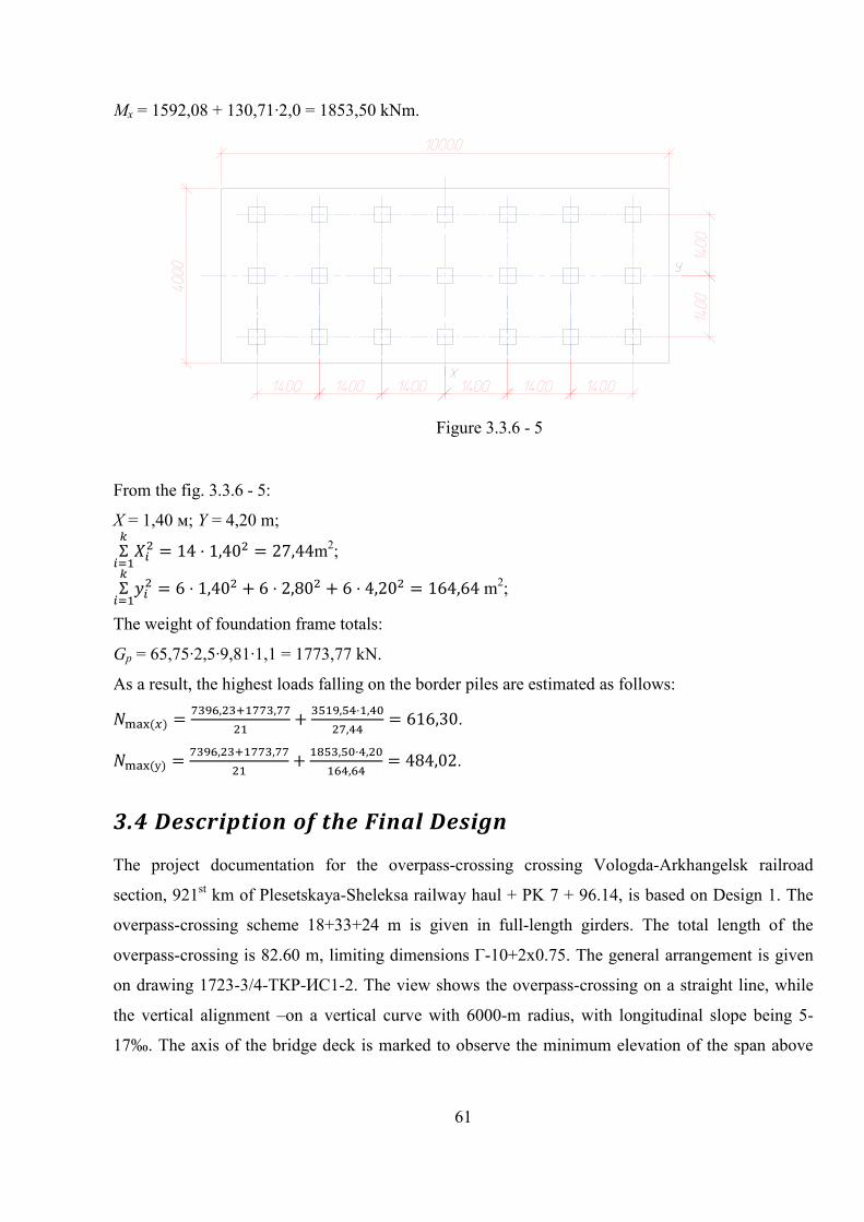
61
Mх = 1592,08 + 130,71∙2,0 = 1853,50 kNm.
Figure 3.3.6 - 5
From the fig. 3.3.6 - 5:
X = 1,40 м; Y = 4,20 m;
Σ𝑖=1
𝑘𝑋𝑖
2 = 14 ⋅ 1,402 = 27,44m2;
Σ𝑖=1
𝑘𝑦𝑖
2 = 6 ⋅ 1,402 + 6 ⋅ 2,802 + 6 ⋅ 4,202 = 164,64 m2;
The weight of foundation frame totals:
Gр = 65,75∙2,5∙9,81∙1,1 = 1773,77 kN.
As a result, the highest loads falling on the border piles are estimated as follows:
𝑁max(𝑥) = 7396,23+1773,7721
+ 3519,54⋅1,4027,44
= 616,30.
𝑁max(у) = 7396,23+1773,7721
+ 1853,50⋅4,20164,64
= 484,02.
3.4 Description of the Final Design The project documentation for the overpass-crossing crossing Vologda-Arkhangelsk railroad
section, 921st km of Plesetskaya-Sheleksa railway haul + PK 7 + 96.14, is based on Design 1. The
overpass-crossing scheme 18+33+24 m is given in full-length girders. The total length of the
overpass-crossing is 82.60 m, limiting dimensions Г-10+2х0.75. The general arrangement is given
on drawing 1723-3/4-ТКР-ИС1-2. The view shows the overpass-crossing on a straight line, while
the vertical alignment –on a vertical curve with 6000-m radius, with longitudinal slope being 5-
17‰. The axis of the bridge deck is marked to observe the minimum elevation of the span above
62
the rail head of the railway to be crossed. According to the technical requirements of JSC “Russian
Railways” branch “Northern Railways” dd. 26.05.2009, the underbridge clearance is 8.5 m. To
ensure the possibility for later widening of the overpass-crossing to provide 4 lanes in case of
increased traffic volumes the 8.6-m underbridge clearance is chosen.
The designed vertical loads:
- truck loading А14,
- wheel load Н14.
The spans are prefabricated ferroconcrete structures made of pre-tensioned girders. Designed as per
TC series 3.503.1-81 ed. 0-4, 7-1 RCR, taking into account the guidelines developed by JSC
Construction Research Institute “Mosty” (“Bridges”), as specified in “Calculations of A14 and H14
loadings on standard ferroconcrete pre-tensioned vehicular girders”. The cross section shows the
spans consist of 5 girders installed at a 2.4-m interval. (See drawing 1723-3/4-ТКР-ИС1-27, -28, -
29).
The span girders are installed on movable (ДШР-РОЧ) and fixed bearings (Н ДШР-РОЧ) and
equipped with tapered liners. Rubber grade НО-68-1. See drawing 1723-3/4-ТКР-ИС1-41 for
girder supporting and bearing members.
Above the railway overhead system wires running under the overpass-crossing, 2-m high safety
shields will be installed on the span.
The end supports OK1 and OK 2 are reinforced concrete one-piece, pile-supported, spill-through
type and independent structures (see drawing 1723-3/4-ТКР-ИС1-6).
The intermediate supports ОП2 and ОП3 are reinforced concrete one-piece, pile-supported
structures, designed applicable to TC series 3.503.1-60 of Voronezh Branch of GIPRODORNII
Design and Research Institute (see drawing 1723-3/4-ТКР-ИС1-16), recalculated for А14 and Н14
loadings. The number of supporting poles – 2, diameter 1020 mm. Pier caps will have embedded
items for lighting supports to be installed.
35х35 cm reinforced concrete piles are specified in TC series 3.500.1-1.93 TMGL. The piles of
abutments and intermediate piers are 8 m long. The piles are driven into feeder wells drilled 90% of
the burial depth. The project provides for trial driving of two piles for each support.
The basement surfaces, support bodies and capping girders contacting the ground require surface
waterproofing, as specified in Construction Norms & Regulations 2.03.11-85.
The project provides for the following bridge floor construction:
- 30-mm thick leveling coat;
63
- pasting waterproofing "Mostoplast", TU 5774-025-01393697-99;
- 30-mm thick protective coat of fine grain concrete, reinforced with flat welded meshes of Bp1
reinforcement steel (5-mm diameter, mesh size 100х100mm as per GOST 23279-85). Meshes
overlap 300 mm;
- vehicular deck is two-layer, with total thickness of 70 mm; the 30-mm thick lower layer is of fine
bituminous concrete, type Б grade 2, as per GOST 9128-84*; the 40-mm thick upper layer is gravel-
mastic, ЩМА-15.
Over the supports, there are gravel-mastic expansion grooves.
Guardrail structure is designed in accordance with TU 5216-063-01393697-2006. Guarding
capacity level – У2 (190 kJ). Guardrail is 0.75 m high.
The barrier railings design is based on “Transbarrier”s engineering design. Barrier railings are 1.1
m high.
All elements of barrier railings and guardrails will be protected by hot galvanizing, with galvanizing
coat being 80-120 micron.
To enhance the durability of structures and render them an aesthetic appearance, the ferroconcrete
surfaces of girders and the aboveground parts of bank and intermediate supports will be coated with
“Steelpaint” finish. Scaffolding will be used when coating the intermediate supports and suspended
scaffold – when coating the girders.
The intersection of the overpass-crossing and elevated approach is secured by half-embedded
composite precast structure, as per TC series 3.503.1-96 RCR. The composite ferroconcrete
approach slabs are 8 m long. 2-m long walkway slabs will be laid within the sidewalk.
The diversion of water from the overpass-crossing carriageway and the operating aisles is provided
by the gutter in the safe margin that directs the water further to catchers through gutters on the bank
slopes. The water intake structures are specified in TC series 503-09-7.84 RCR. The transverse
grade of the bridge deck is 20‰ and is created on the spans due to bearing blocks height difference.
As draining backfill in the overpass-crossing-approach intersection, sandy ground with min. 2m/day
post-compact filtration coefficient will be used.
The cone slopes will be secured with 0.17-m high “Renault” beddings. The beddings will be laid
according to ОСТ 10 323 -2003, ВСН-АПК 2.30.05.001-03 documented requirements.
At the start of the overpass-crossing, 0.75 m long ferroconcrete stairs will be mounted, as per TC
series 3.503.1-96 RCR.
The 3-D visualization of designing bridges and junctions.
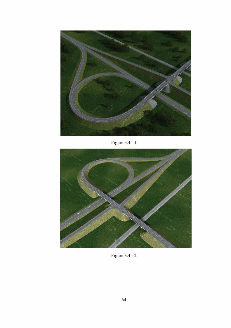
64
Figure 3.4 - 1
Figure 3.4 - 2
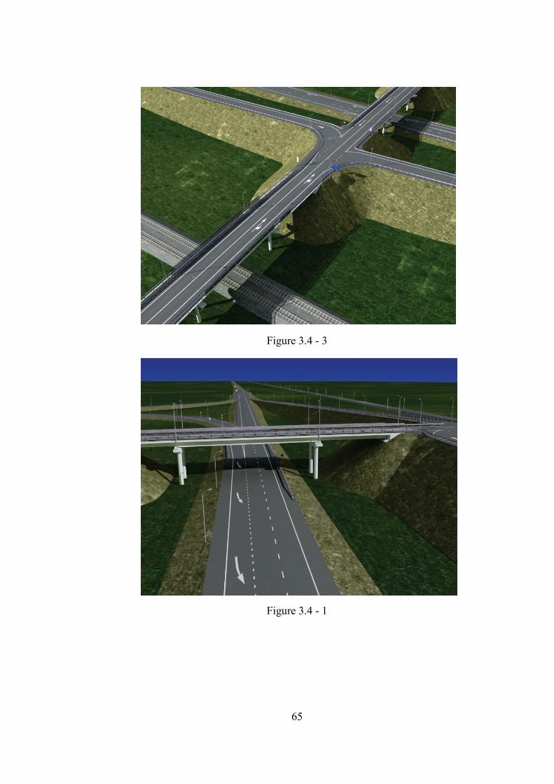
65
Figure 3.4 - 3
Figure 3.4 - 1
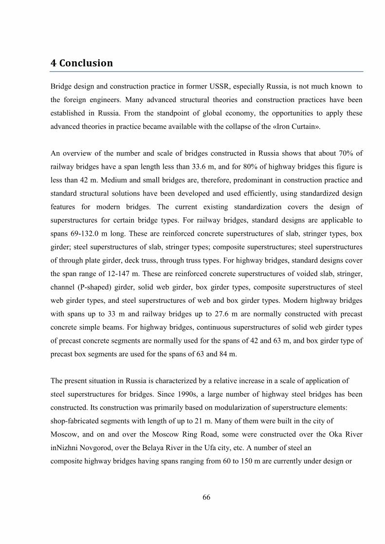
66
4 Conclusion
Bridge design and construction practice in former USSR, especially Russia, is not much known to
the foreign engineers. Many advanced structural theories and construction practices have been
established in Russia. From the standpoint of global economy, the opportunities to apply these
advanced theories in practice became available with the collapse of the «Iron Curtain».
An overview of the number and scale of bridges constructed in Russia shows that about 70% of
railway bridges have a span length less than 33.6 m, and for 80% of highway bridges this figure is
less than 42 m. Medium and small bridges are, therefore, predominant in construction practice and
standard structural solutions have been developed and used efficiently, using standardized design
features for modern bridges. The current existing standardization covers the design of
superstructures for certain bridge types. For railway bridges, standard designs are applicable to
spans 69-132.0 m long. These are reinforced concrete superstructures of slab, stringer types, box
girder; steel superstructures of slab, stringer types; composite superstructures; steel superstructures
of through plate girder, deck truss, through truss types. For highway bridges, standard designs cover
the span range of 12-147 m. These are reinforced concrete superstructures of voided slab, stringer,
channel (P-shaped) girder, solid web girder, box girder types, composite superstructures of steel
web girder types, and steel superstructures of web and box girder types. Modern highway bridges
with spans up to 33 m and railway bridges up to 27.6 m are normally constructed with precast
concrete simple beams. For highway bridges, continuous superstructures of solid web girder types
of precast concrete segments are normally used for the spans of 42 and 63 m, and box girder type of
precast box segments are used for the spans of 63 and 84 m.
The present situation in Russia is characterized by a relative increase in a scale of application of
steel superstructures for bridges. Since 1990s, a large number of highway steel bridges has been
constructed. Its construction was primarily based on modularization of superstructure elements:
shop-fabricated segments with length of up to 21 m. Many of them were built in the city of
Moscow, and on and over the Moscow Ring Road, some were constructed over the Oka River
inNizhni Novgorod, over the Belaya River in the Ufa city, etc. A number of steel an
composite highway bridges having spans ranging from 60 to 150 m are currently under design or
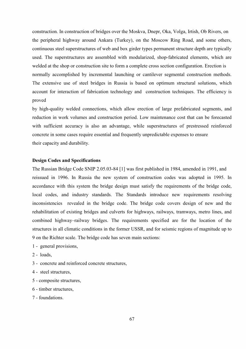
67
construction. In construction of bridges over the Moskva, Dnepr, Oka, Volga, Irtish, Ob Rivers, on
the peripheral highway around Ankara (Turkey), on the Moscow Ring Road, and some others,
continuous steel superstructures of web and box girder types permanent structure depth are typically
used. The superstructures are assembled with modularized, shop-fabricated elements, which are
welded at the shop or construction site to form a complete cross section configuration. Erection is
normally accomplished by incremental launching or cantilever segmental construction methods.
The extensive use of steel bridges in Russia is based on optimum structural solutions, which
account for interaction of fabrication technology and construction techniques. The efficiency is
proved
by high-quality welded connections, which allow erection of large prefabricated segments, and
reduction in work volumes and construction period. Low maintenance cost that can be forecasted
with sufficient accuracy is also an advantage, while superstructures of prestressed reinforced
concrete in some cases require essential and frequently unpredictable expenses to ensure
their capacity and durability.
Design Codes and Specifications
The Russian Bridge Code SNIP 2.05.03-84 [1] was first published in 1984, amended in 1991, and
reissued in 1996. In Russia the new system of construction codes was adopted in 1995. In
accordance with this system the bridge design must satisfy the requirements of the bridge code,
local codes, and industry standards. The Standards introduce new requirements resolving
inconsistencies revealed in the bridge code. The bridge code covers design of new and the
rehabilitation of existing bridges and culverts for highways, railways, tramways, metro lines, and
combined highway–railway bridges. The requirements specified are for the location of the
structures in all climatic conditions in the former USSR, and for seismic regions of magnitude up to
9 on the Richter scale. The bridge code has seven main sections:
1 - general provisions,
2 - loads,
3 - concrete and reinforced concrete structures,
4 - steel structures,
5 - composite structures,
6 - timber structures,
7 - foundations.
68
In 1995, the Moscow City Department of Transportation developed and adapted “Additional
Requirements for Design and Construction of Bridges and Overpasses on the Moscow Ring
Highway” to supplement the bridge code when design the highway widening and rehabilitation of
the 50 bridge structures on the Moscow Ring Highway. The live load is increased by 27% in the
“Additional Requirements.” In 1998 the Moscow City Department issued the draft standard TSN
32 “Regional Building Norms for Design of Town Bridge Structures in Moscow” [6] on the basis
of the “Additional Requirements.” The new standard specifies an increased live load and abnormal
loading and reflects the necessity to improve reliability and durability of bridge structures. The
final TSN 32 was issued in 1998.
The current regulatory framework of civil engineering in the Russian Federation fully ensures
reliability and safety of construction projects both operated and planned. Accidents never happen
because of compliance with applicable rules, but only as a result of violation thereof. Due to several
reasons, development and updating of the civil engineering regulatory documents have not been
conducted for the last two decades, whereas said regulatory framework went out of date to certain
extent, in particular, in terms of using new materials and technologies. It affected the quality of
design to significantly lesser extent as evidenced by the practice of construction of many civil
engineering projects for the same period including some unique ones.
As construction design standards, the Eurocodes are based on a substantial body (over a thousand)
of reference standards for materials, methods for testing thereof, production procedures etc., many
of which are still unknown or have been examined neither by design nor by manufacturing entities.
Therefore, mastering the entire regulatory framework of the European construction standards
including the Eurocodes should follow a complex approach. At the moment, approximation of
regulatory frameworks of the Customs Union member states and EAEC has started.
Actualization of Russian´s SNIP and GOST, studying and mastering standards of the European
Union, and development of a unified regulatory framework for the Customs Union of Russia,
Belarus and Kazakhstan, and the EAEC – all of these processes should be seen in conjunction, and
managed within a framework of a coordinated inter-state program designed more than a year. As is
evident from the table, significant package of SNiP for design of different types of structures is a
direct analog of the Eurocodes. It should be noted that the calculation methods for building
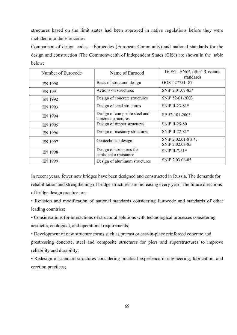
69
structures based on the limit states had been approved in native regulations before they were
included into the Eurocodes.
Comparison of design codes – Eurocodes (European Community) and national standards for the
design and construction (The Commonwealth of Independent States (CIS)) are shown in the table
below:
Number of Eurocode Name of Eurocod GOST, SNiP, other Russians standards
EN 1990 Basis of structural design GOST 27751- 87
EN 1991 Actions on structures SNiP 2.01.07-85*
EN 1992 Design of concrete structures SNiP 52-01-2003
EN 1993 Design of steel structures SNiP II-23-81*
EN 1994 Design of composite steel and concrete structures
SP 52-101-2003
EN 1995 Design of timber structures SNiP II-25-80
EN 1996 Design of masonry structures SNiP II-22-81*
EN 1997 Geotechnical design SNiP 2.02.01-8 3 *, SNiP 2.02.03-85
EN 1998 Design of structures for earthquake resistance
SNiP II-7-81*
EN 1999 Design of aluminum structures SNiP 2.03.06-85
In recent years, fewer new bridges have been designed and constructed in Russia. The demands for
rehabilitation and strengthening of bridge structures are increasing every year. The future directions
of bridge design practice are:
• Revision and modification of national standards considering Eurocode and standards of other
leading countries;
• Considerations for interactions of structural solutions with technological processes considering
aesthetic, ecological, and operational requirements;
• Development of new structure forms such as precast or cast-in-place reinforced concrete and
prestressing concrete, steel and composite structures for piers and superstructures to improve
reliability and durability;
• Redesign of standard structures considering practical experience in engineering, fabrication, and
erection practices;

70
• Unification of shop-fabricated steel elements ready for erection to a maximum dimension fitting
the transportation requirements, improvement of precast concrete decks, improvement of corrosion
protection systems to a life span up to 12 years;
• Development of relevant mobile equipment and practical considerations of cast-in-place concrete
bridges.
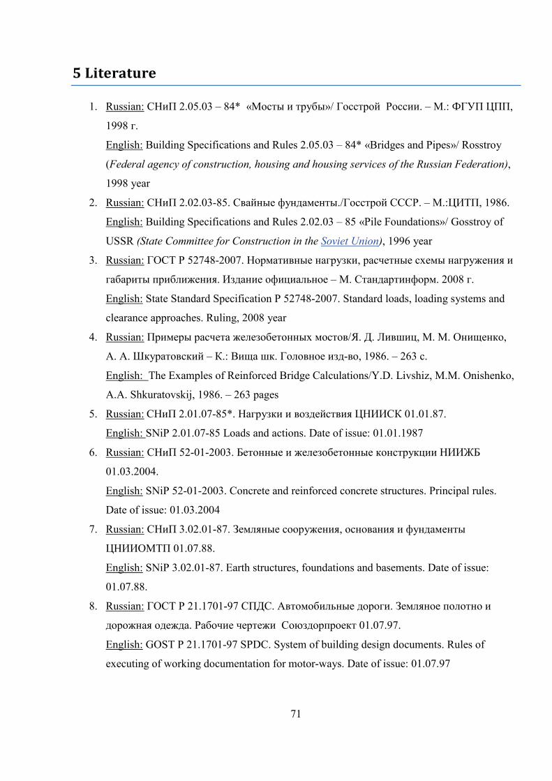
71
5 Literature
1. Russian: СНиП 2.05.03 – 84* «Мосты и трубы»/ Госстрой России. – М.: ФГУП ЦПП,
1998 г.
English: Building Specifications and Rules 2.05.03 – 84* «Bridges and Pipes»/ Rosstroy
(Federal agency of construction, housing and housing services of the Russian Federation),
1998 year
2. Russian: СНиП 2.02.03-85. Свайные фундаменты./Госстрой СССР. – М.:ЦИТП, 1986.
English: Building Specifications and Rules 2.02.03 – 85 «Pile Foundations»/ Gosstroy of
USSR (State Committee for Construction in the Soviet Union), 1996 year
3. Russian: ГОСТ Р 52748-2007. Нормативные нагрузки, расчетные схемы нагружения и
габариты приближения. Издание официальное – М. Стандартинформ. 2008 г.
English: State Standard Specification P 52748-2007. Standard loads, loading systems and
clearance approaches. Ruling, 2008 year
4. Russian: Примеры расчета железобетонных мостов/Я. Д. Лившиц, М. М. Онищенко,
А. А. Шкуратовский – К.: Вища шк. Головное изд-во, 1986. – 263 с.
English: The Examples of Reinforced Bridge Calculations/Y.D. Livshiz, M.M. Onishenko,
A.A. Shkuratovskij, 1986. – 263 pages
5. Russian: СНиП 2.01.07-85*. Нагрузки и воздействия ЦНИИСК 01.01.87.
English: SNiP 2.01.07-85 Loads and actions. Date of issue: 01.01.1987
6. Russian: СНиП 52-01-2003. Бетонные и железобетонные конструкции НИИЖБ
01.03.2004.
English: SNiP 52-01-2003. Concrete and reinforced concrete structures. Principal rules.
Date of issue: 01.03.2004
7. Russian: СНиП 3.02.01-87. Земляные сооружения, основания и фундаменты
ЦНИИОМТП 01.07.88.
English: SNiP 3.02.01-87. Earth structures, foundations and basements. Date of issue:
01.07.88.
8. Russian: ГОСТ Р 21.1701-97 СПДС. Автомобильные дороги. Земляное полотно и
дорожная одежда. Рабочие чертежи Союздорпроект 01.07.97.
English: GOST P 21.1701-97 SPDC. System of building design documents. Rules of
executing of working documentation for motor-ways. Date of issue: 01.07.97
72
6 Appendix
The list of drawings (1723-3/4-TKP-ИС1-9 – is the registration number of drawing in
designing company OAO “Sevdorproekt”, Russia):
1. 1723-3/4-TKP-ИС1-3 – Variants of bridges (page 71)
2. 1723-3/4-TKP-ИС1-4 – General view Railway (page 72)
3. 1723-3/4-TKP-ИС1-5 – Bearing support on the pile foundation (page 73)
4. 1723-3/4-TKP-ИС1-6 – Edge bearings (page 74)
5. 1723-3/4-TKP-ИС1-7 – Abutment footing (page 75)
6. 1723-3/4-TKP-ИС1-8 – Abutment footing. Reinforcing layout (page 76)
7. 1723-3/4-TKP-ИС1-9 – Back wall and wings wall. Decking layout (page 77)
8. 1723-3/4-TKP-ИС1-11 – Pile foundation. Decking layout (page 78)
9. 1723-3/4-TKP-ИС1-15 – Bridge pedestals of abutments OK1(OK4), (page 79)
10. 1723-3/4-TKP-ИС1-16 – Intermediate pier ОП2 (ОП3), (page 80)
11. 1723-3/4-TKP-ИС1-41 – Bearing units (page 81)
12. 1723-3/4-TKP-ИС1-27, -28, - 29 – Cross-section layout (page 81-82-83)
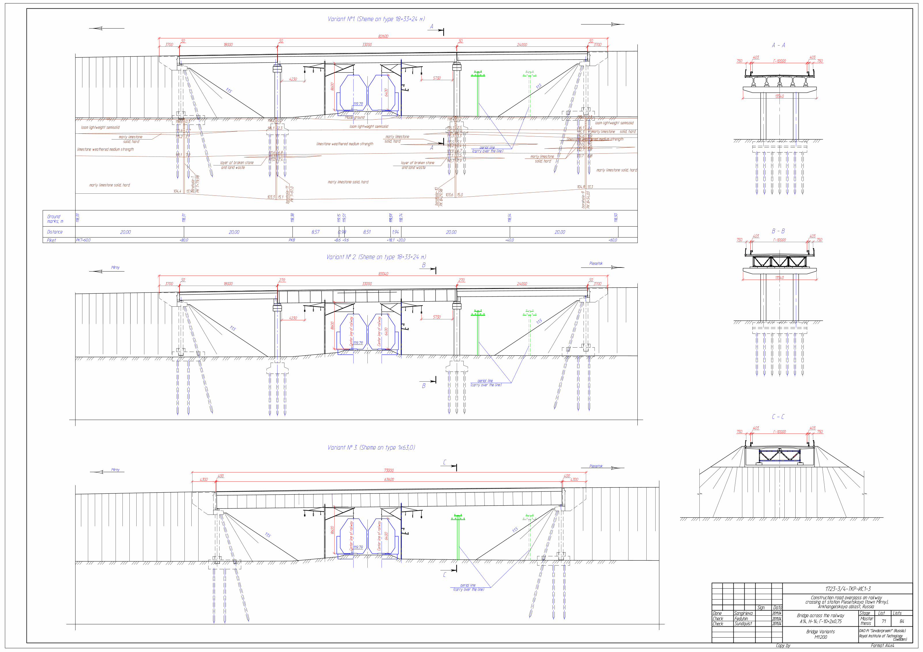
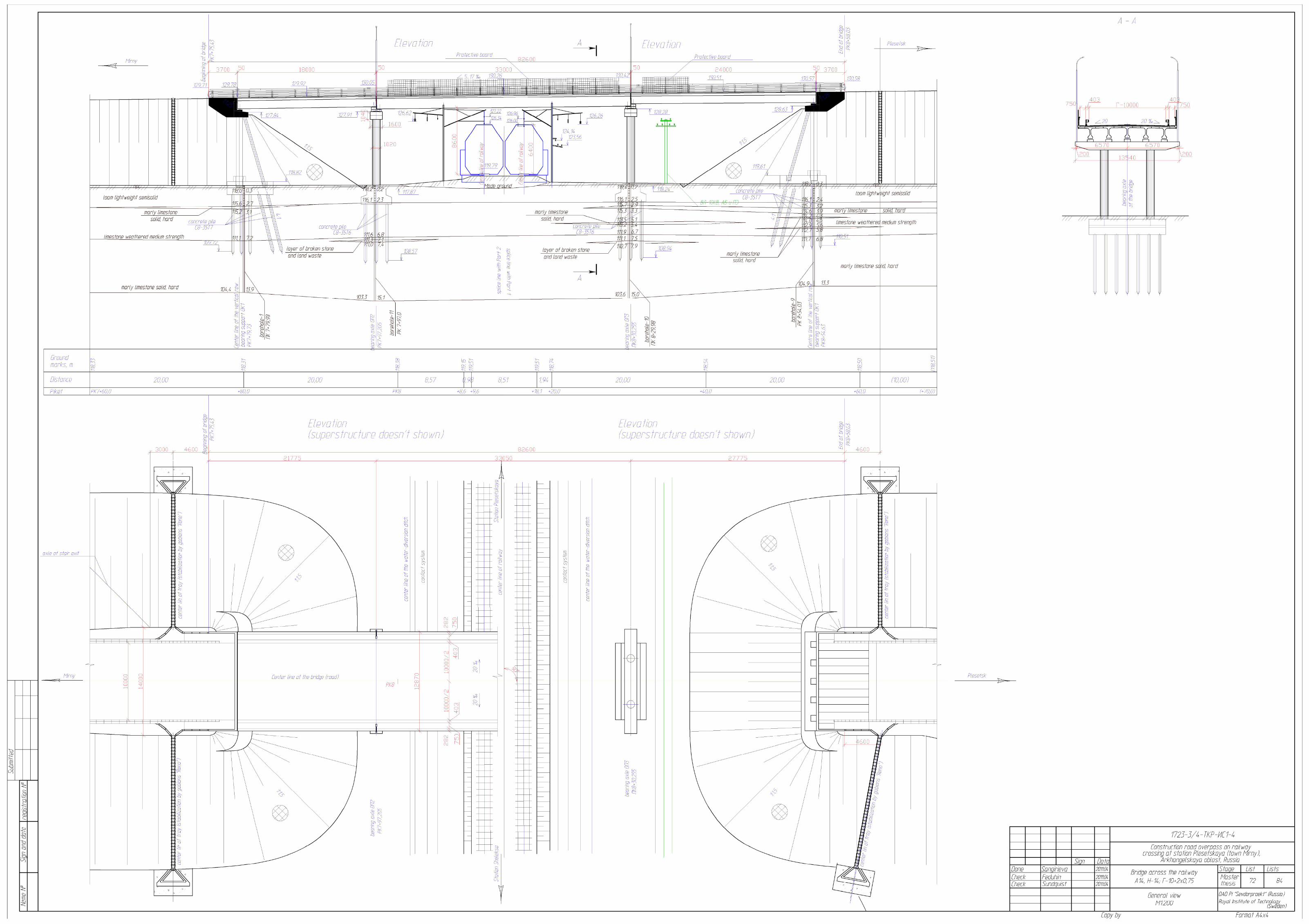
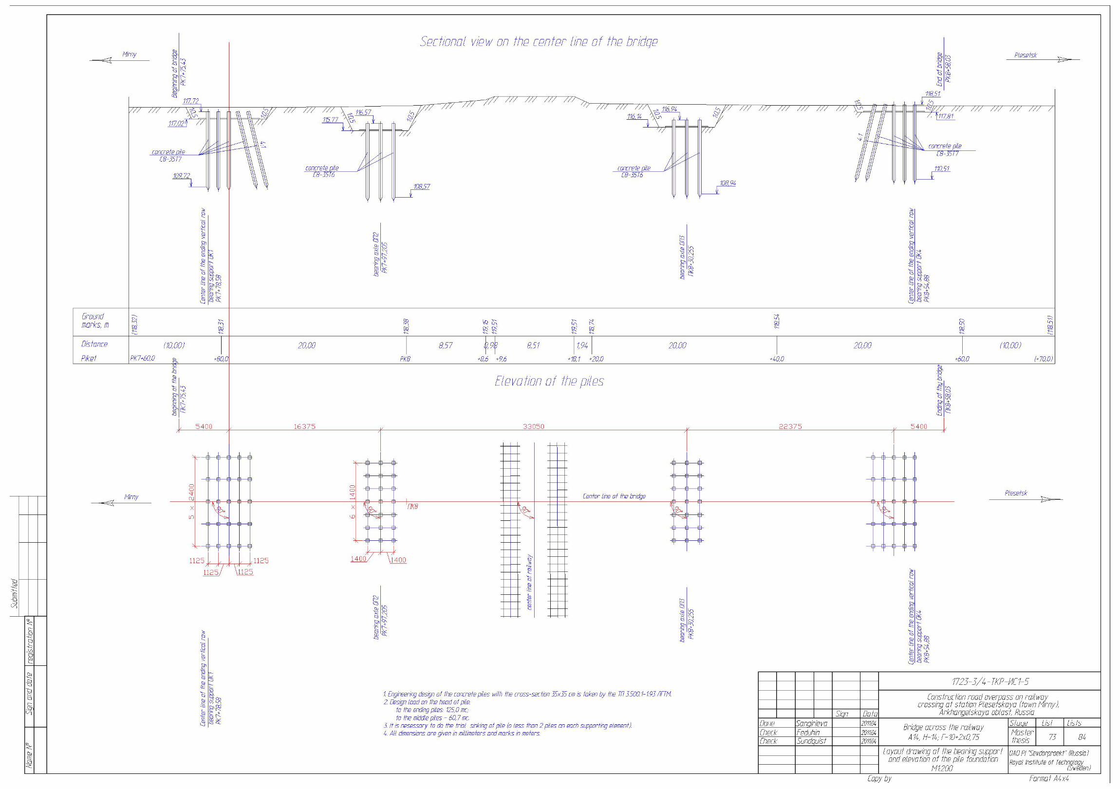
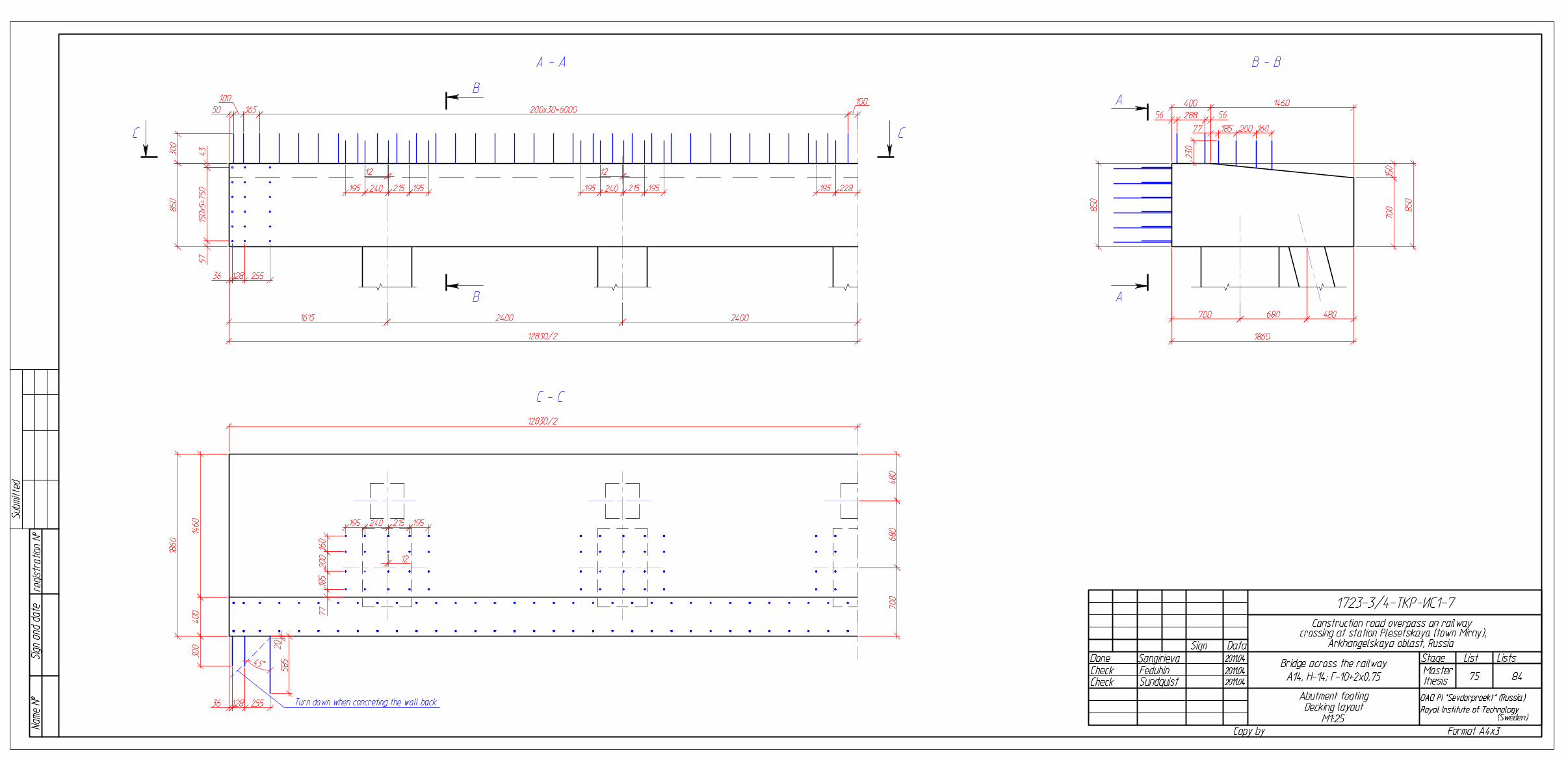
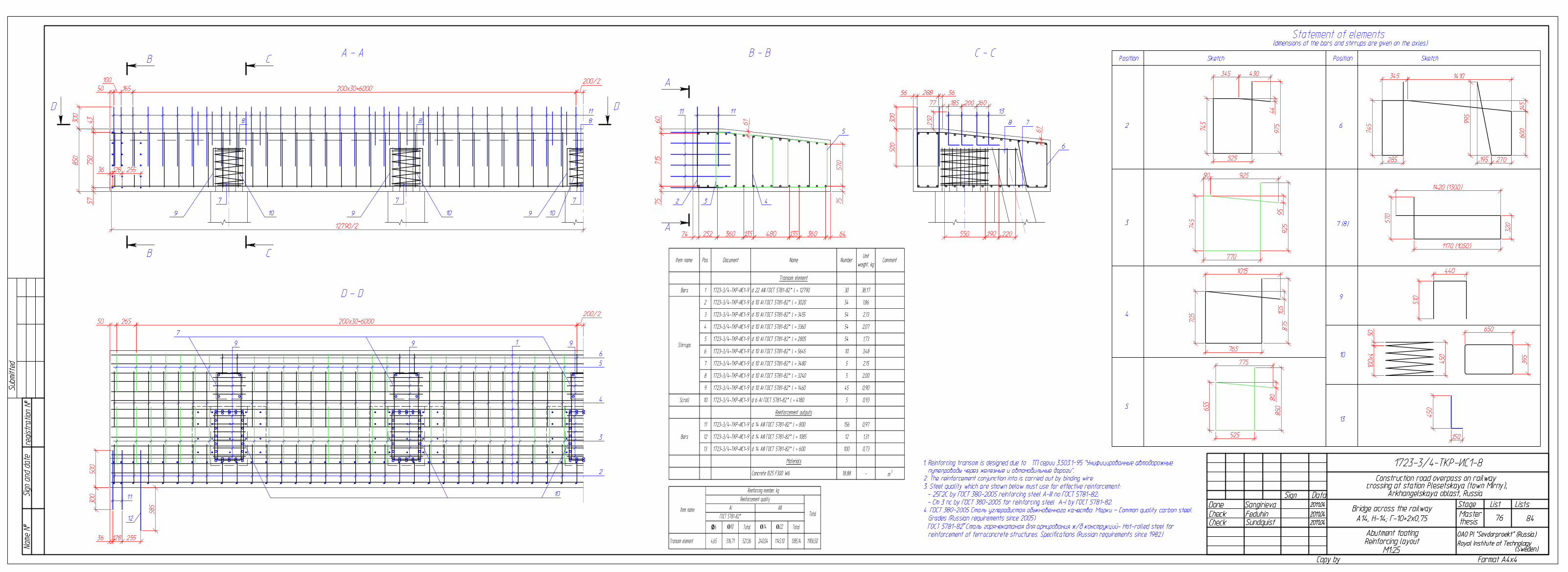
Item name Pos. Document Name NumberUnit
weight, kgComment
Transom element
Bars 1 1723-3/4-ТКР-ИС1-9 d 22 АIII ГОСТ 5781-82* l = 12790 30 38,17
2 1723-3/4-ТКР-ИС1-9 d 10 АI ГОСТ 5781-82* l = 3020 54 1,86
3 1723-3/4-ТКР-ИС1-9 d 10 АI ГОСТ 5781-82* l = 3455 54 2,13
4 1723-3/4-ТКР-ИС1-9 d 10 АI ГОСТ 5781-82* l = 3360 54 2,07
5 1723-3/4-ТКР-ИС1-9 d 10 АI ГОСТ 5781-82* l = 2805 54 1,73
6 1723-3/4-ТКР-ИС1-9 d 10 АI ГОСТ 5781-82* l = 5645 10 3,48
7 1723-3/4-ТКР-ИС1-9 d 10 АI ГОСТ 5781-82* l = 3480 5 2,15
8 1723-3/4-ТКР-ИС1-9 d 10 АI ГОСТ 5781-82* l = 3240 5 2,00
9 1723-3/4-ТКР-ИС1-9 d 10 АI ГОСТ 5781-82* l = 1460 45 0,90
Scroll 10 1723-3/4-ТКР-ИС1-9 d 6 АI ГОСТ 5781-82* l = 4180 5 0,93
Reinforcement outputs
11 1723-3/4-ТКР-ИС1-9 d 14 АIII ГОСТ 5781-82* l = 800 156 0,97
12 1723-3/4-ТКР-ИС1-9 d 14 АIII ГОСТ 5781-82* l = 1085 12 1,31
13 1723-3/4-ТКР-ИС1-9 d 14 АIII ГОСТ 5781-82* l = 600 100 0,73
Materials
Concrete B25 F300 W6 18,88 - m 3
Bars
Stirrups
Ø6 Ø10 Total Ø14 Ø22 Total
Transom element 4,65 516,71 521,36 240,04 1145,10 1385,14 1906,50
Reinforcement quality
ГОСТ 5781-82*Item name
TotalАIIIАI
Reinforcing member, kg
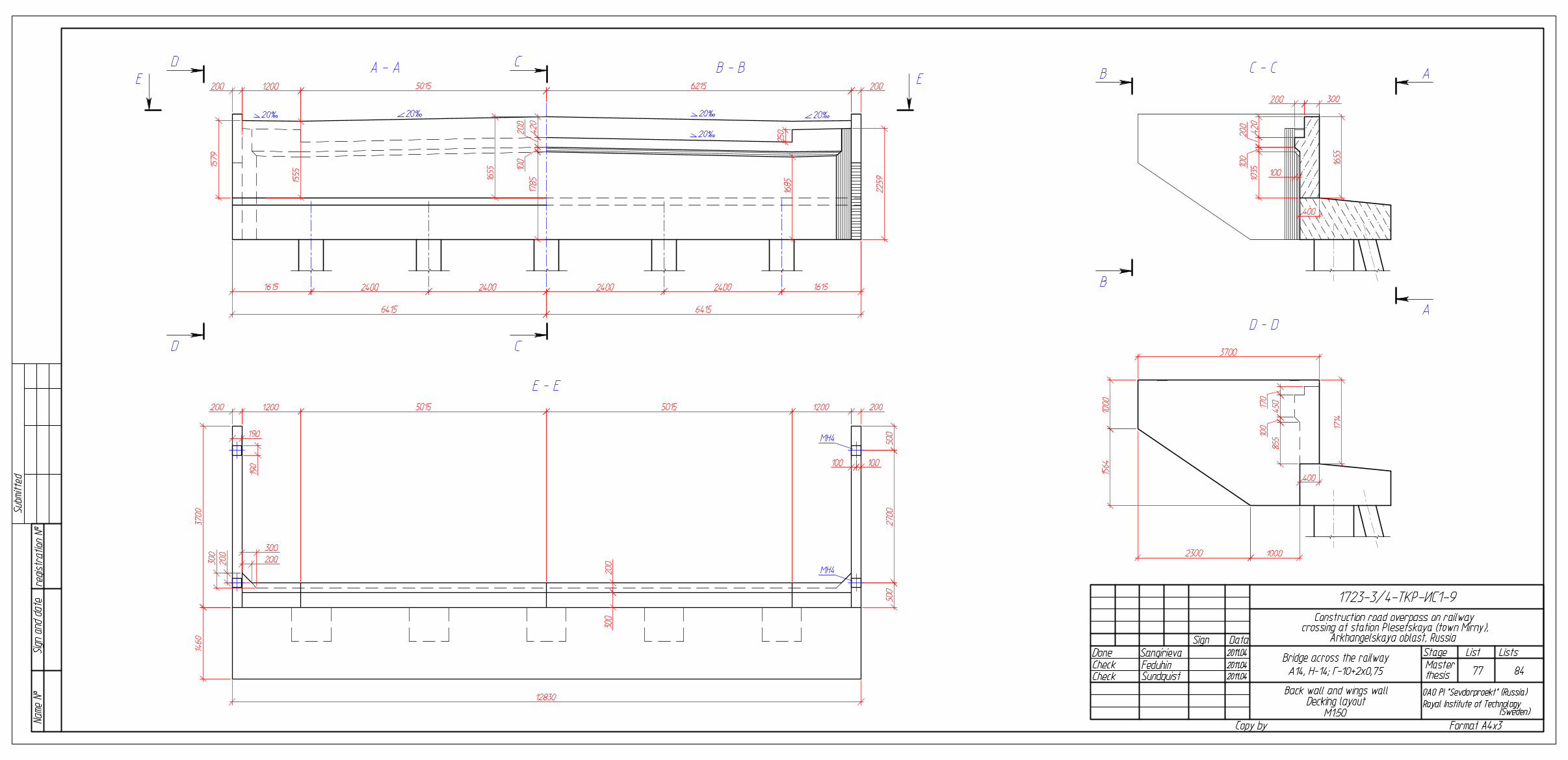
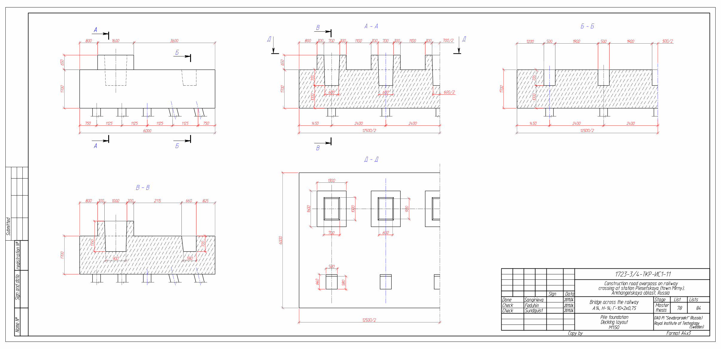
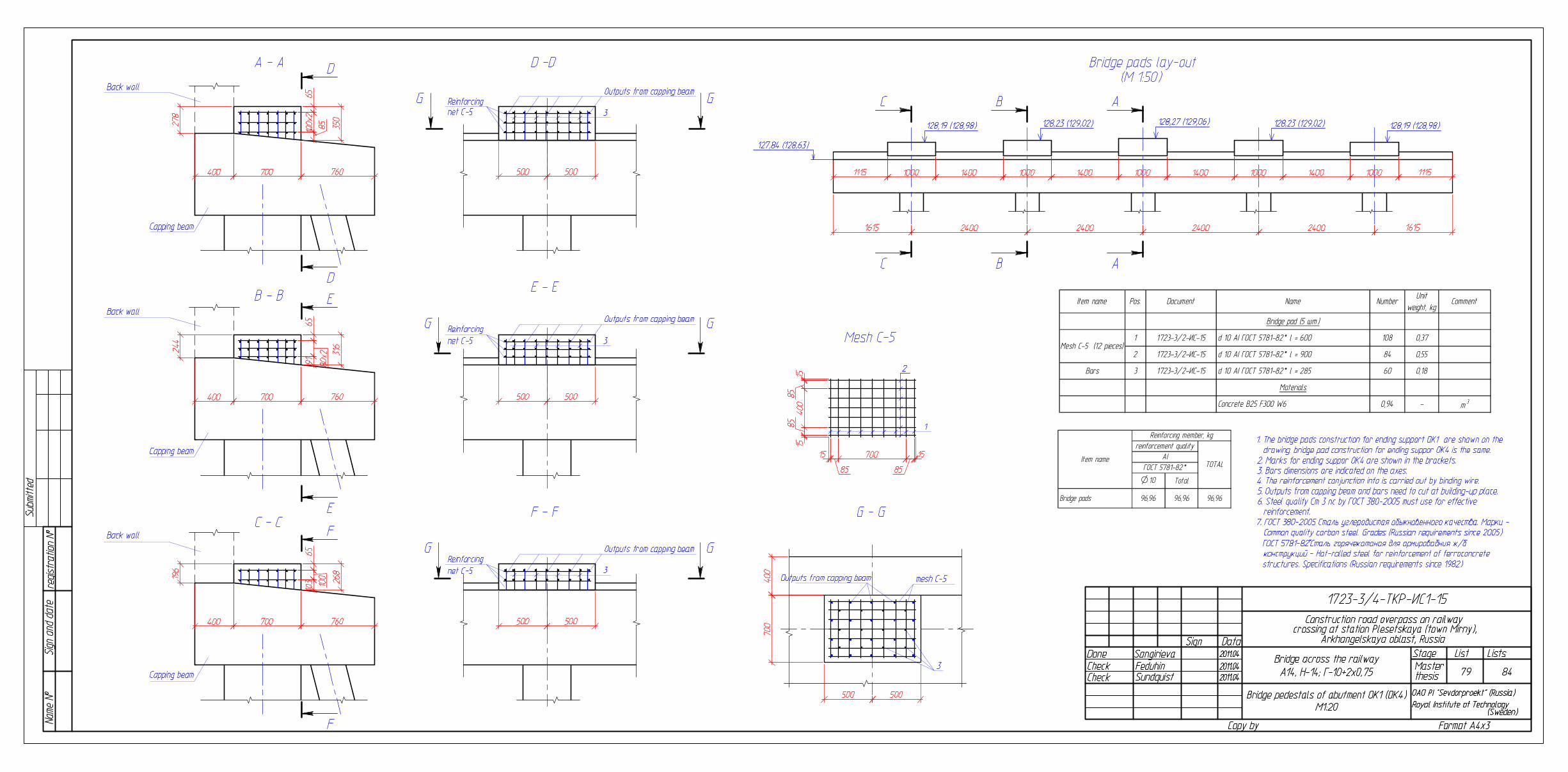
Item name Pos. Document Name NumberUnit
weight, kgComment
Bridge pad (5 шт.)
1 1723-3/2-ИС-15 d 10 АI ГОСТ 5781-82* l = 600 108 0,37
2 1723-3/2-ИС-15 d 10 АI ГОСТ 5781-82* l = 900 84 0,55
Bars 3 1723-3/2-ИС-15 d 10 АI ГОСТ 5781-82* l = 285 60 0,18
Materials
Concrete B25 F300 W6 0,94 - m 3
Mesh С-5 (12 pieces)
n 10 Total
Bridge pads 96,96 96,96 96,96
reinforcement quality
ГОСТ 5781-82*Item name
TOTALАI
Reinforcing member, kg
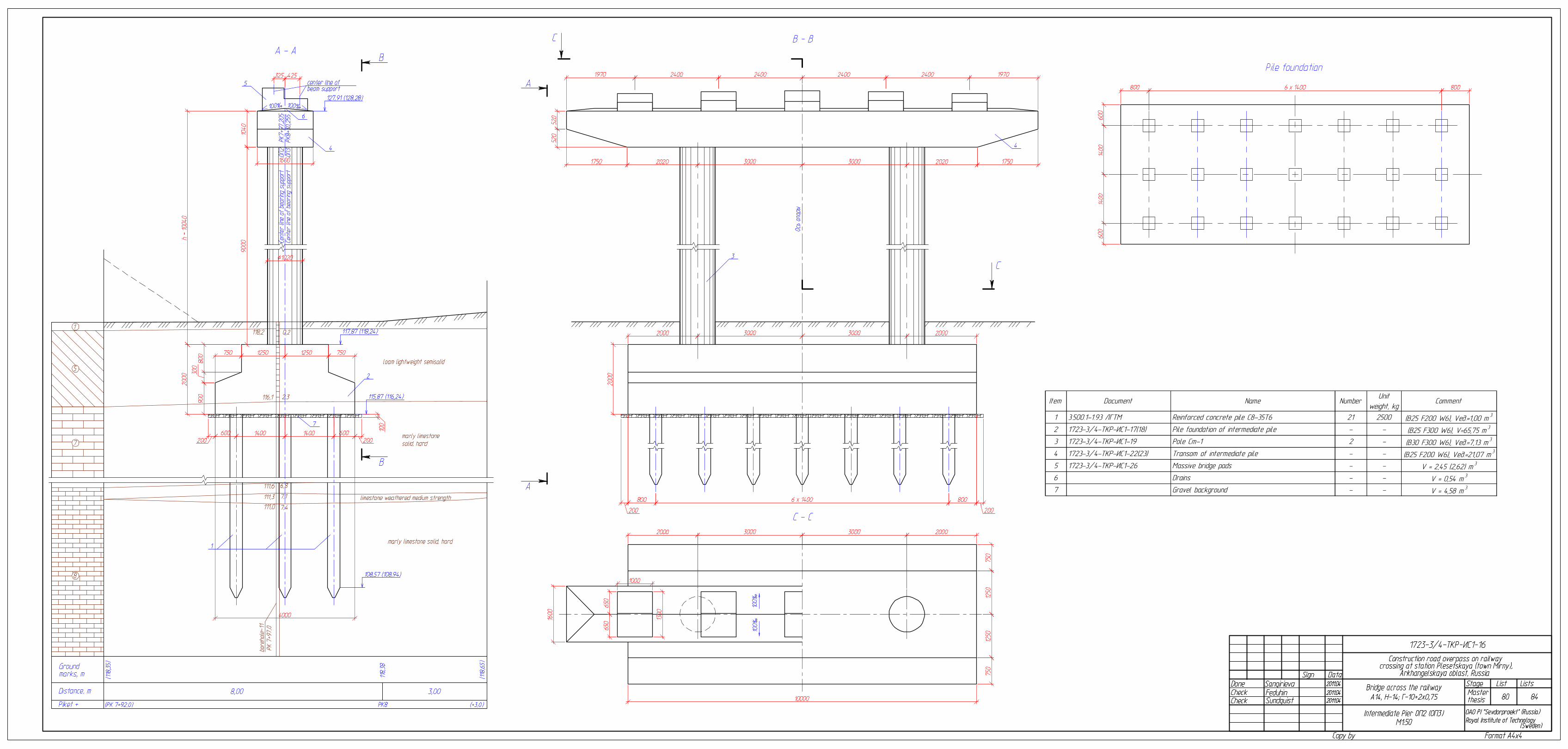
Item Document Name NumberUnit
weight, kgComment
1 3.500.1-1.93 ЛГТМ Reinforced concrete pile С8-35Т6 21 2500 (В25 F200 W6), Vед.=1,00 m 3
2 1723-3/4-ТКР-ИС1-17(18) Pile foundation of intermediate pile - - (В25 F300 W6), V=65,75 m 3
3 1723-3/4-ТКР-ИС1-19 Pole Ст-1 2 - (В30 F300 W6), Vед.=7,13 m 3
4 1723-3/4-ТКР-ИС1-22(23) Transom of intermediate pile - - (В25 F200 W6), Vед.=21,07 m 3
5 1723-3/4-ТКР-ИС1-26 Massive bridge pads - - V = 2,45 (2,62) m 3
6 Drains - - V = 0,54 m 3
7 Gravel background - - V = 4,58 m 3
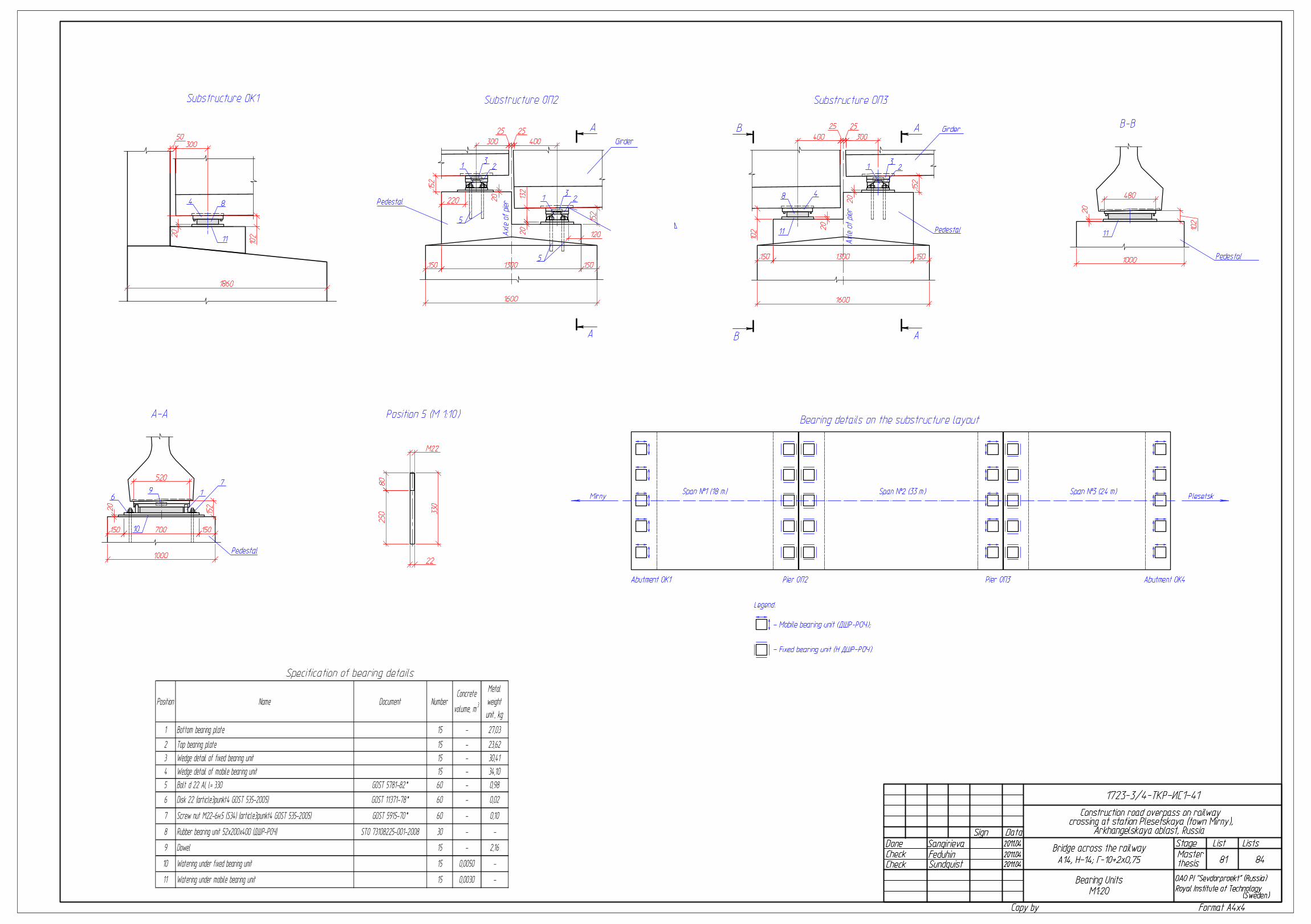
Position Name Document NumberConcrete
volume, m 3
Metal weight unit., kg
1 Bottom bearing plate 15 - 27,03
2 Top bearing plate 15 - 23,62
3 Wedge detail of fixed bearing unit 15 - 30,41
4 Wedge detail of mobile bearing unit 15 - 34,10
5 Bolt d 22 АI, l= 330 GOST 5781-82* 60 - 0,98
6 Disk 22 (article3punkt4 GOST 535-2005) GOST 11371-78* 60 - 0,02
7 Screw nut М22-6н.5 (S34) (article3punkt4 GOST 535-2005) GOST 5915-70* 60 - 0,10
8 Rubber bearing unit 52х200х400 (ДШР-РОЧ) STO 73108225-001-2008 30 - -
9 Dowel 15 - 2,16
10 Watering under fixed bearing unit 15 0,0050 -
11 Watering under mobile bearing unit 15 0,0030 -