Embed Size (px)
Citation preview
1
ISETTA
USE AND MAINTENANCE MANUAL
428000372237
EN
ISA S.r.l.Via del Lavoro, 5
06083 Bastia Umbra - Perugia - Italy
Tel. +39 075 80171 - Fax +39 075 8000900
www.isaitaly.com
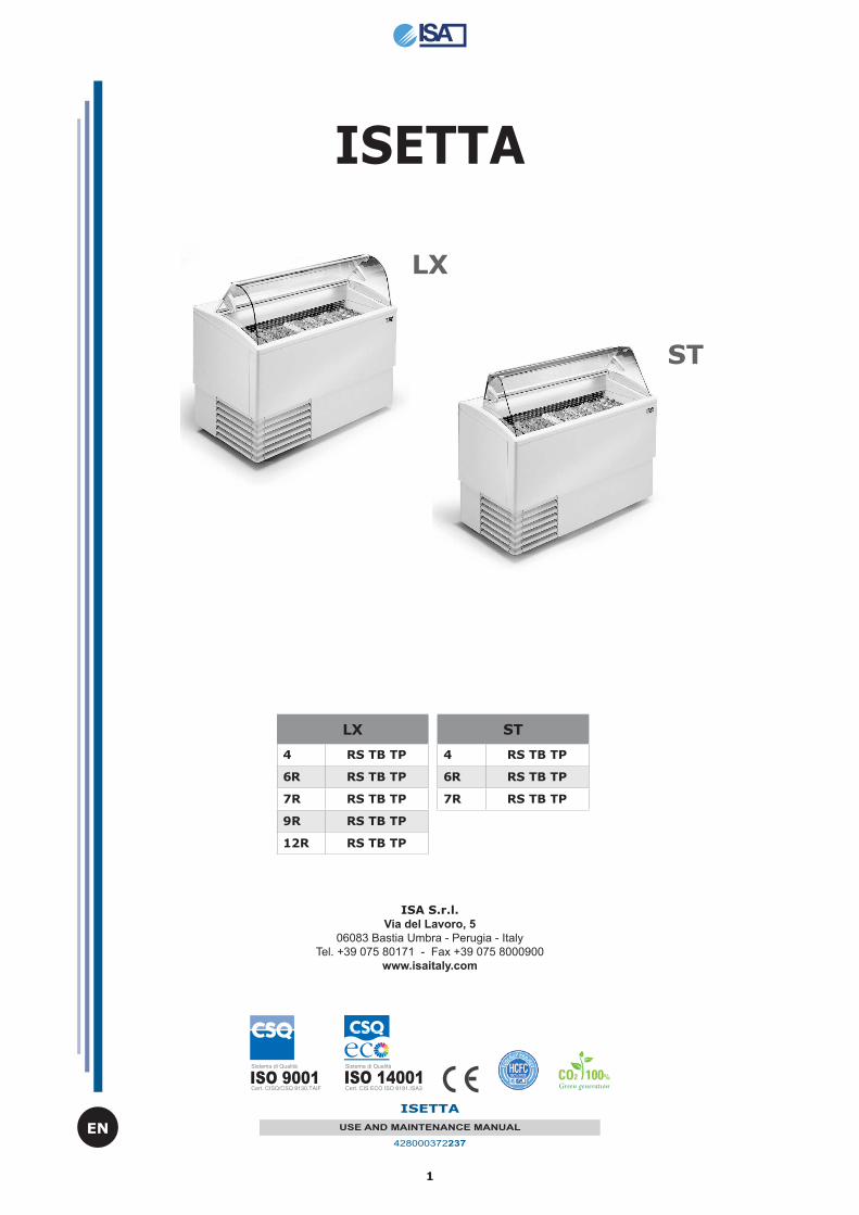
ISETTA
LX
ST
LX
4 RS TB TP
6R RS TB TP
7R RS TB TP
9R RS TB TP
12R RS TB TP
ST
4 RS TB TP
6R RS TB TP
7R RS TB TP
2
ISETTA
USE AND MAINTENANCE MANUAL
428000372237
EN
1. NOTES / IMPORTANT NOTES . . . . . . . . . . . . . . . . . . . . . . . . . . . . . . . . . .4
1.1 Introduction . . . . . . . . . . . . . . . . . . . . . . . . . . . . . . . . . . . . . . . . . . . . . . .5
1.2 Manufacturer's contact details . . . . . . . . . . . . . . . . . . . . . . . . . . . . . . . . . . .5
2. SAFETY. . . . . . . . . . . . . . . . . . . . . . . . . . . . . . . . . . . . . . . . . . . . . . . . . . .6
2.1 Staff training. . . . . . . . . . . . . . . . . . . . . . . . . . . . . . . . . . . . . . . . . . . . . . .6
2.2 Safety devices applied . . . . . . . . . . . . . . . . . . . . . . . . . . . . . . . . . . . . . . . .6
2.2.1 Safety devices included . . . . . . . . . . . . . . . . . . . . . . . . . . . . . . . . . . . . . .6
2.2.2 Fixed protective devices . . . . . . . . . . . . . . . . . . . . . . . . . . . . . . . . . . . . .6
2.2.3 Disconnecting electrical power supply . . . . . . . . . . . . . . . . . . . . . . . . . . . .7
2.3 Residual risks . . . . . . . . . . . . . . . . . . . . . . . . . . . . . . . . . . . . . . . . . . . . . .7
2.3.1 Risk of contact with parts under stress . . . . . . . . . . . . . . . . . . . . . . . . . . .7
2.3.2 Fires . . . . . . . . . . . . . . . . . . . . . . . . . . . . . . . . . . . . . . . . . . . . . . . . . . .7
2.3.3 Explosions . . . . . . . . . . . . . . . . . . . . . . . . . . . . . . . . . . . . . . . . . . . . . . .8
2.3.4 Slipping . . . . . . . . . . . . . . . . . . . . . . . . . . . . . . . . . . . . . . . . . . . . . . . . .8
2.3.5 Tripping . . . . . . . . . . . . . . . . . . . . . . . . . . . . . . . . . . . . . . . . . . . . . . . . .8
2.3.6 Circuit faults . . . . . . . . . . . . . . . . . . . . . . . . . . . . . . . . . . . . . . . . . . . . .8
2.4 Warning signs (if any) . . . . . . . . . . . . . . . . . . . . . . . . . . . . . . . . . . . . . . . .8
2.5 Refrigerant R290 . . . . . . . . . . . . . . . . . . . . . . . . . . . . . . . . . . . . . . . . . . . .9
3. DISPOSING OF EXHAUST MATERIALS . . . . . . . . . . . . . . . . . . . . . . . . . .10
4. INSTALLATION. . . . . . . . . . . . . . . . . . . . . . . . . . . . . . . . . . . . . . . . . . . .11
4.1 Storage and unpacking . . . . . . . . . . . . . . . . . . . . . . . . . . . . . . . . . . . . . .11
4.2 Installation, positioning and ambient conditions . . . . . . . . . . . . . . . . . . . . .11
4.3 Electrical connection . . . . . . . . . . . . . . . . . . . . . . . . . . . . . . . . . . . . . . . .11
5. TECHNICAL SPECIFICATIONS . . . . . . . . . . . . . . . . . . . . . . . . . . . . . . . .12
5.1 Installation . . . . . . . . . . . . . . . . . . . . . . . . . . . . . . . . . . . . . . . . . . . . . .14
5.2 Positioning . . . . . . . . . . . . . . . . . . . . . . . . . . . . . . . . . . . . . . . . . . . . . . .14
5.3 Load limits . . . . . . . . . . . . . . . . . . . . . . . . . . . . . . . . . . . . . . . . . . . . . . .14
5.4 Optional features . . . . . . . . . . . . . . . . . . . . . . . . . . . . . . . . . . . . . . . . . . .16
6. EQUIPMENT DESCRIPTION . . . . . . . . . . . . . . . . . . . . . . . . . . . . . . . . . .15
6.1 Composition . . . . . . . . . . . . . . . . . . . . . . . . . . . . . . . . . . . . . . . . . . . . . .15
6.2 Identifi cation . . . . . . . . . . . . . . . . . . . . . . . . . . . . . . . . . . . . . . . . . . . . .15
7. CONTROL PANEL . . . . . . . . . . . . . . . . . . . . . . . . . . . . . . . . . . . . . . . . . .16
7.1 Start-up . . . . . . . . . . . . . . . . . . . . . . . . . . . . . . . . . . . . . . . . . . . . . . . . .16
7.2 User Interface ELIWELL EW974 . . . . . . . . . . . . . . . . . . . . . . . . . . . . . . . . .17
7.3 User Interface DIXELL XR44CX . . . . . . . . . . . . . . . . . . . . . . . . . . . . . . . . .18
8. ROUTINE MAINTENANCE and REGULAR CHECKS . . . . . . . . . . . . . . . . . .20
8.1 Cleaning the inside the cabinet . . . . . . . . . . . . . . . . . . . . . . . . . . . . . . . . .20
8.2 Access condensing unit . . . . . . . . . . . . . . . . . . . . . . . . . . . . . . . . . . . . . .21
8.3 Cleanings condensing unit . . . . . . . . . . . . . . . . . . . . . . . . . . . . . . . . . . . .21
8.4 External cleaning operations . . . . . . . . . . . . . . . . . . . . . . . . . . . . . . . . . . .21
9. MAINTENANCE . . . . . . . . . . . . . . . . . . . . . . . . . . . . . . . . . . . . . . . . . . .22
10. TECHNICAL ASSISTANCE . . . . . . . . . . . . . . . . . . . . . . . . . . . . . . . . . . .23
10.1 Faults . . . . . . . . . . . . . . . . . . . . . . . . . . . . . . . . . . . . . . . . . . . . . . . . . .23
10.2 List of alarms on the electronic controller . . . . . . . . . . . . . . . . . . . . . . . . .24
11. GENERALWARRANTY TERMS AND CONDITIONS . . . . . . . . . . . . . . . . .24
12. ANNEXES . . . . . . . . . . . . . . . . . . . . . . . . . . . . . . . . . . . . . . . . . . . . . . .25
3
ISETTA
USE AND MAINTENANCE MANUAL
428000372237
EN
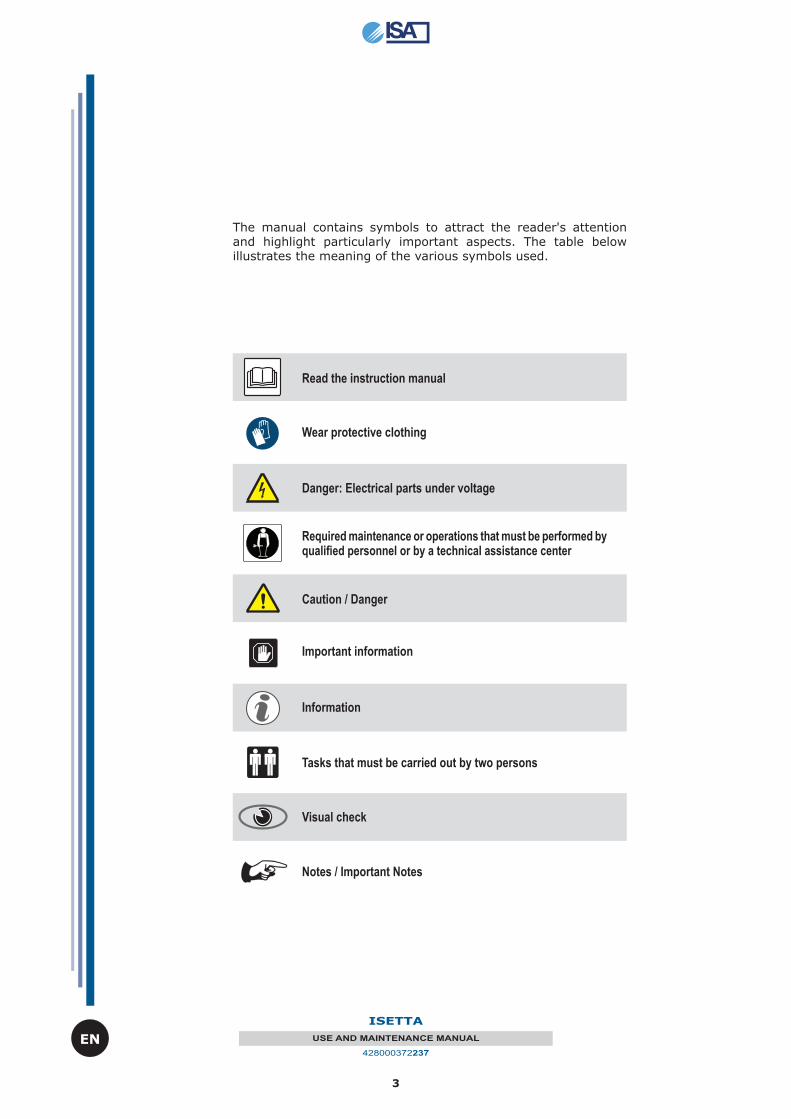
The manual contains symbols to attract the reader's attention and highlight particularly important aspects. The table below illustrates the meaning of the various symbols used.
Caution / Danger
Important information
Tasks that must be carried out by two persons
Information
Wear protective clothing
Read the instruction manual
Required maintenance or operations that must be performed by qualifi ed personnel or by a technical assistance center
Danger: Electrical parts under voltage
Visual check
Notes / Important Notes
4
ISETTA
USE AND MAINTENANCE MANUAL
428000372237
EN
1. NOTES / IMPORTANT NOTES
The content of this manual is of technical nature and is owned by ISA S.r.l. It is forbidden to reproduce, circulate or modify all or part of its content without written consent. Any infringement will be legally pursued.
The manual and the conformity certifi cate are an integral part of the equipment and should always accompany the product in the event of a transfer to a new location or to a new owner. The user is responsible for the integrity of these documents, for their consultation and during the whole life cycle of the equipment itself. Keep this manual in a safe place. It should be made available near the equipment for consultation at any time. If lost or destroyed, you can request a copy of this manual from ISA S.r.l. by specifying the exact model, serial number and year of manufacture. The manual refl ects the manufacturing technology at the time of supply. The manufacturer reserves the right to modify its products in any way it deems necessary, with no obligation to update manuals and machines relating to previous manufacturing batches.
This equipment is not intended for use by persons (including children) with reduced physical, sensory or mental capabilities or by persons lacking the necessary experience and knowledge, unless they are supervised by a person responsible for their safety who has instructed them on how to use the equipment. Children should be supervised to ensure that they do not play with the equipment. Always refer to this manual before going ahead with any operation. Before doing any type of work, disconnect the equipment from the power supply. Any work on electric and electronic parts or cooling system components should only be carried out by trained personnel in compliance with current laws.
The Manufacturer cannot be held liable for any injury to persons or animals, or damage to the product itself in the event of:
• improper use of the equipment or use of the appliance by unqualifi ed or unauthorised personnel;
• failure to comply with current legislation; • incorrect installation and/or power supply faults; • failure to observe the instructions contained in this Manual;• failure to follow the maintenance programme; • unauthorised modifi cations; • installation of non-original spare parts in the equipment;• installation and use of the equipment for purposes other than those for which the appliance
was designed and sold;• tampering with or damage to the power supply cable.
Liability for applying the safety instructions contained in this manual is held by the technical personnel responsible for the intended use of the equipment, who should ensure that authorised personnel:
• are qualifi ed to carry out the requested activity;• are aware of, and carefully comply with, the instructions contained in this document;• are aware of, and apply, the general safety standards applicable to the equipment.
Failure to comply with safety standards may result in injury to personnel and damage to the equipment components and control unit. The user can contact the dealer to request additional information not contained in this document, or suggest improvements, at any time.
Before the product is delivered to the customer, it is essential that a trained technical member of staff checks that the equipment is operating correctly in order to achieve maximum performance.
5
ISETTA
USE AND MAINTENANCE MANUAL
428000372237
EN
1.1 Introduction
ISA S.r.l. employs materials of the best quality and as they enter the company, we constantly monitor their storage and the use as part of the manufacturing process to prevent damage, deterioration and failure. All manufacturing elements are designed and manufactured in order to guarantee reliability and high safety standards. All the equipment items are subjected to a strict testing procedure before delivery. However, please bear in mind that product performance over time depends on correct use and adequate maintenance. This manual contains the necessary instructions to maintain the equipment's initial appearance and functions over time..
NoteIn order not to compromise the functionality and safety of the equipment, installation and maintenance operations that are especially complex have not been documented in this manual and are carried out by specialised technicians of the manufacturer.
The Use and Maintenance Manual contains the necessary information for understanding how the equipment works and how to use it properly, namely: the technical description of the various operational units, equipment and safety systems, operations, how to use the instruments and the interpretation of any diagnostics reports, main procedures and information relating to routine maintenance. For correct use of the equipment, the working environment should comply with current health and safety standards.
The safety requirements, indications, standards and notes illustrated in the various chapters of this manual are aimed at establishing a code of conduct and a series of obligations to be observed when performing the various activities, in order to create safe conditions for personnel, the equipment and the surrounding environment. To ensure the operator's safety, the devices of the equipment should be kept in constant working order. This manual is intended to illustrate the use and maintenance of the equipment. The operator has a responsibility and duty to carefully observe the instructions contained within it. The safety standards reported in this document are intended for trained, authorised personnel responsible for:
- transport-- installation- operations- management- maintenance- cleaning, decommissioning, and disposal which are the only authorised use of the equipment discussed in this manual
AttentionReading this manual, albeit in full, is no substitute for adequate user experience. Therefore it should only be considered a useful reminder of technical features and the main operations to perform.
WarningThe installers and users are required to read and understand all the instructions contained herein before they carry out any operation on the equipment.
1.2 Manufacturer's contact details
ISA S.r.l.
Via del Lavoro, 506083 - Bastia Umbra - Perugia - ItalyTel. +39 075 80171Fax +39 075 8000900
www.isaitaly.com
6
ISETTA
USE AND MAINTENANCE MANUAL
428000372237
EN
2. SAFETY
The buyer is responsible for training personnel using the appliance on the risks, safety devices and general health and safety rules required by the laws of the country where the equipment is installed.Users/operators should be aware of the position of all the controls and how they work, as well as of the features of the equipment.They should also read this manual in its entirely.Maintenance work should be conducted by qualifi ed personnel after the equipment has been prepared adequately.
DangerUnauthorised tampering with or replacement of one or more parts of the equipment, the use of ac-cessories that change its performance, and the use o spare parts other than those recommended may cause the risk of injury.
DangerBefore doing any type of work, the equipment must always be disconnected from the power supply.
Any work on electric parts or cooling system components should only be carried out by trained personnel in compliance with current laws.
2.1 Staff training
The buyer is responsible for ensuring personnel who will use the equipment and the maintenance technical staff are instructed and trained adequately. The manufacturer is available for advice, clarifi cations, etc. so that the operator and technical staff can use the equipment correctly.
AttentionThe equipment is designed for industrial use.
2.2 Safety devices applied
The appliance is equipped with the following safety devices:
2.2.1 SAFETY DEVICES INCLUDED
2.2.2 FIXED PROTECTIVE DEVICES
2.2.3 DISCONNECTING ELECTRICAL POWER SUPPLY
2.2.1 Safety devices included
Devices whose operation prevents risks from occurring when using the equipment (e.g. fuses, pressure switches, protective devices, thermal switches, etc.).
2.2.2 Fixed protective devices
Fixed protective devices consist of fi xed perimeter shields, which are used to prevent external parts from entering the equipment.
DangerIt is absolutely forbidden to restart the equipment after it has been serviced, without fi rst properly restoring the panelling.
AttentionYou should check the integrity of fi xed panels and corresponding fi xings to the frame, focusing in particular on the protective panels.
7
ISETTA
USE AND MAINTENANCE MANUAL
428000372237
EN
2.2.3 Disconnecting electrical power supply
Before conducting any maintenance works on the equipment or part of it, it is necessary to section the power supply that powers it.
DangerWe therefore remind you, if maintenance is carried out and the operator cannot prevent bystanders from accidentally closing the circuit, to fully disconnect the equipment from the electric network.
2.3 Residual risks
During design the manufacturer examined all the areas or parts at risk. Therefore, all necessary precautions have been taken to prevent risks to persons and damage to the equipment as mentioned in the previous paragraphs.
AttentionPeriodically check that all the safety devices are operating correctly.Do not disassemble the fi xed protective devices.Do not introduce foreign objects or tools in the area of work.
Although the equipment is fi tted with the aforementioned safety devices, there are still some risks that cannot be eliminated, but reduced via corrective actions by the fi nal integrator and correct operational procedures.
Below is a summary of the remaining risks associated with the equipment during:
- Normal operation- Adjustments and tweaking- Maintenance- Cleaning
2.3.1 Risk of contact with live parts
Risk of breaking or damaging the electrical components of the equipment, with a possible reduction in safety levels, following a short circuit.Before connecting the electricity supply, make sure there is no ongoing maintenance work.
AttentionBefore hooking up the equipment to its power supply, check that the short-circuit voltage in the place of installation is not higher than the one indicated on the protective switches on the electrical panel. If it is, the user is required to have appropriate limiting devices installed. It is strictly forbidden to conduct any electrical modifi cation, in order to prevent additional unforeseen hazards and risks.
2.3.2 Fires
DangerIn the event of a fi re, immediately disconnect the master switch from the main power supply line.
8
ISETTA
USE AND MAINTENANCE MANUAL
428000372237
EN
2.3.3 Explosions
The equipment must not be located in an area classifi ed as an explosion risk according to 1999/92/EC, such as:
Zone 0An area in which there is a permanent, long-lasting or frequently explosive atmosphere made up of a mixture of air and fl ammable substances in the form of gases, fumes or steam.
Zone 1An area in which the formation of an explosive atmosphere, made up of a mixture of air and fl ammable substances in the form of gases, fumes or steam is occasionally probable during normal activities.
Zone 20An area in which there is a permanent, long-lasting or frequently explosive atmosphere in the form of clouds of combustible dust in the air.
Zone 21An area in which the formation of an explosive atmosphere in the form of clouds of combustible dust is occasionally probable during normal activities.
2.3.4 Slipping
Any leaks in the areas surrounding the equipment may cause personnel to slip.Check that there are no leaks and keep these areas clean at all times.
2.3.5 Tripping
Generally untidy deposits of material may constitute a tripping hazard and a total or partial obstruction of emergency exit routes.You should ensure that operating and transit areas and emergency exit routes are free from obstacles in compliance with current legislation.
2.3.6 Circuit faults
Owing to potential faults, safety circuits may become less effective, which results in lower safety levels.You should check the operational condition of the equipment's safety devices installed regularly.
2.4 Warning signs (if any)
Depending on the various types of risks identifi ed, warning labels signalling a danger, inviting to caution, or pointing to a mandatory requirement are fi tted on the equipment, in accordance with the applicable legislation which establishes the graphic symbols that are to be used on plants.The signs are located in clearly visible positions.
AttentionIt is absolutely forbidden to remove the warning signs fi tted on the equipment.The user is responsible for replacing warning signs that, owing to wear, become unreadable.
9
ISETTA
USE AND MAINTENANCE MANUAL
428000372237
EN
2.5 Refrigerant R290
This equipment contains a small amount of R290 refrigerant, an environmentally compatible gas, but one that is highly fl ammable. Be very carefully during transport, installation of the equipment and disposal to not damage the refrigerant circuit pipes.Maintenance must be performed by qualifi ed personnel that has been to work with fl ammable refrigerants.
IN THE EVENT OF DAMAGE:Keep the equipment far from fl ames or sources of ignition. Ventilate the room for several minutes. Turn the unit off, pull the plug. Inform the customer service department. The more refrigerant containing an appliance, the greater must be the environment in which there is the unit. In areas too small, in the event of leakage can form a fl ammable mixture of air and gas. The volume of the room where the equipment is located must be at least 19 m³ for each chiller system present.
USE: Never use electrical appliances inside the appliance. Do not damage the refrigerant circuit. Do not use mechanical devices or other means to accelerate the defrosting process other than those recommended by the manufacturer. Keep the ventilation openings in the equipment housing or structure free of obstructions.
DANGER OF EXPLOSION:Do not store products containing combustible gas propellants and explosive substances inside the equipment.
INSTALLATION OF THE APPLIANCE:Is suitable for installation in a dry, well ventilated room. The installation area must not be exposed to direct sunlight and must not be near heat sources such as stoves, heaters, etc. If installation next to a heat source is unavoidable, use a suitable insulating panel.
10
ISETTA
USE AND MAINTENANCE MANUAL
428000372237
EN
3. DISPOSING OF EXHAUST MATERIALS
During normal operation, the equipment does not generate any environmental contamination. At the end of its life cycle, or if it is necessary to proceed to permanent decommissioning, we recommend following the procedures below:
DISPOSAL (User)
The symbol, applied to either the product or its packaging, indicates that the product should not be considered as normal domestic waste, but should be taken to a waste collection point for the recycling of electrical and electronic appliances. The correct disposal of this product helps to prevent potential negative consequences that might derive from inadequate product disposal. For detailed information about recycling this product, contact your council, your local waste collection service or the store where you purchased the product.
PROCEDURES FOR THE DISPOSAL and RECYCLING OF THE EQUIPMENT AT THE ENDOF ITS LIFETIME (Authorised Institutions)
1. Turn off the equipment and unplug it.2. Remove the lamps (if installed). These should be disposed of separately.3. Remove the power units and the electronic cards. These should be disposed of separately.4. Remove all the independent parts (grids, casings, profi les, etc.) and group them according to shared features in order to access the heat exchangers, pipes, cables, etc. and be careful not to damage the cooling circuit.5. Remove all mobile parts (doors, sliding doors, glass parts, etc.) and group the various materials according to their features.6. Check the type of coolant on the label located inside the counter. Extract the refrigerant and have it disposed of by authorised centres.7. Disconnect the evaporator, condenser, compressor, pipes and fans. These are made of copper, aluminium, steel and plastic and should therefore be disposed of separately.8. When you have removed all the housings and the various components of the shell, proceed to separate the elements based on their type of material (plastic, sheets, polyurethane, copper, etc.) and group them according to similarity.
All recyclable materials and waste should be processed and recycled by professionals, in compliance with the laws in force in the country where the equipment is installed.The company responsible for recycling the materials should be registered and certifi ed as a waste disposal service in accordance with the laws in force in the country where the equipment is installed.
AttentionIllegal disposal of the product by the owner will result in administrative sanctions as required by current laws.Disposal of the product should comply with current laws on the disposal of coolant liquids and mineral oils.
ImportantIf the equipment does not bear the barred trash-bin symbol, this means disposal of the product is not responsibility of the manufacturer. If so, the current laws on waste disposal always apply.
Additional informationFurther information on the disposal of liquid coolant, oils and other substances is available on the safety data sheet corresponding to the substance itself.
11
ISETTA
USE AND MAINTENANCE MANUAL
428000372237
EN
4. INSTALLATION
This manual provides information on how to correctly unpack the equipment, the procedures to position it and describes how to connect the equipment to the electric network.
4.1 Storage and unpacking
The equipment, with or without the packaging, should be carefully stored inside warehouses or in areas away from the elements and direct sunlight, at a temperature between 0 and +40 °C. The equipment should only be moved by qualifi ed personnel operating forklift trucks, the power of which should be suited to handling the weight of the product: during this operation the equipment MUST be placed on the special pallet supplied.
Unpack the equipment by removing the screws fi xing it to the pallet.All packaging materials are recyclable and should be disposed of in accordance with local regulations. Please destroy "plastic" bags to prevent them from becoming hazardous to children (suffocation).
4.2 Installation, positioning and ambient conditions
AttentionThere should be a good air fl ow around the compressor and condensing unit. Therefore the area around the unit should not be obstructed by boxes or other objects.Position the equipment far from sources of heat (radiators, stoves of any kind, etc.) and far from the in-fl ux of continuous air (caused for instance by fans, air-conditioned inlets, etc.). Avoid also exposing the equipment to direct sun rays. All of these factors cause the temperature inside the refrigerated compartment to rise with harmful consequences for the equipment's functionality and costly consumption of energy. Do not use the equipment outdoors and do not leave it exposed to rain.
4.3 Electrical connection
AttentionCheck that the voltage indicated on the appliance is the same as the value on the appliance identifi cation label and in the table provided in paragraph 2 of this manual, and check that the required voltage is suitable. Check on the socket that the power supply voltage provides rated voltage (±10%) when you start up the compressor.The plug should be directly connected to the electrical socket. It is forbidden to connect the plug to the socket by means of multiple socket extensions or adaptors.The socket of the plant must have a device to disconnect it from the power network (sized to fi t the load and compliant with the current legislation) which guarantees complete power cut-off in conditions of overvoltage III (3) and which must therefore protect the circuits against grounding failures, overloads, and short-circuits.Do not route the electricity cable in passageways.
AttentionEarthing is necessary and mandatory by law.
12
ISETTA
USE AND MAINTENANCE MANUAL
428000372237
EN
5. TECHNICAL SPECIFICATIONS
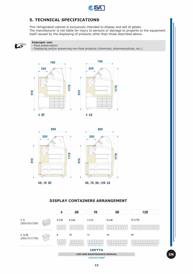
This refrigerated cabinet is exclusively intended to display and sell of gelato.The manufacturer is not liable for injury to persons or damage to property or the equipment itself caused by the displaying of products other than those described above.
Improper use:- Food preservation.- Displaying and/or preserving non-food products (chemicals, pharmaceuticals, etc.).
DISPLAY CONTAINERS ARRANGEMENT
13
ISETTA
USE AND MAINTENANCE MANUAL
428000372237
EN
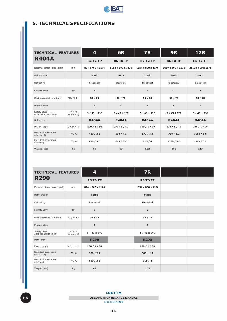
TECHNICAL FEATURES
R404A4 6R 7R 9R 12R
RS TB TP RS TB TP RS TB TP RS TB TP RS TB TP
External dimensions (lxpxh) mm 824 x 760 x 1176 1184 x 800 x 1176 1354 x 800 x 1176 1659 x 800 x 1176 2119 x 800 x 1176
Refrigeration Static Static Static Static Static
Defrosting Electrical Electrical Electrical Electrical Electrical
Climate class N° 7 7 7 7 7
Environmental conditions °C / % RH 35 / 75 35 / 75 35 / 75 35 / 75 35 / 75
Product class S S S S S
Safety class (CEI EN 60335-2-89)
N° / °C (ambient)
5 / 43 ± 2°C 5 / 43 ± 2°C 5 / 43 ± 2°C 5 / 43 ± 2°C 5 / 43 ± 2°C
Refrigerant R404A R404A R404A R404A R404A
Power supply V / ph / Hz 230 / 1 / 50 230 / 1 / 50 230 / 1 / 50 230 / 1 / 50 230 / 1 / 50
Electrical absorption (standard)
W / A 450 / 3.3 590 / 4.1 870 / 5.3 730 / 3.2 1060 / 5.6
Electrical absorption (defrost)
W / A 810 / 3.8 810 / 3.7 915 / 4 1330 / 5.8 1770 / 8.2
Weight (net) Kg 69 97 102 160 217
TECHNICAL FEATURES
R2904 7R
RS TB TP RS TB TP
External dimensions (lxpxh) mm 824 x 760 x 1176 1354 x 800 x 1176
Refrigeration Static Static
Defrosting Electrical Electrical
Climate class N° 7 7
Environmental conditions °C / % RH 35 / 75 35 / 75
Product class S S
Safety class (CEI EN 60335-2-89)
N° / °C (ambient)
5 / 43 ± 2°C 5 / 43 ± 2°C
Refrigerant R290 R290
Power supply V / ph / Hz 230 / 1 / 50 230 / 1 / 50
Electrical absorption (standard)
W / A 300 / 2.4 500 / 2.6
Electrical absorption (defrost)
W / A 810 / 3.8 915 / 4
Weight (net) Kg 69 102
5. TECHNICAL SPECIFICATIONS
14
ISETTA
USE AND MAINTENANCE MANUAL
428000372237
EN
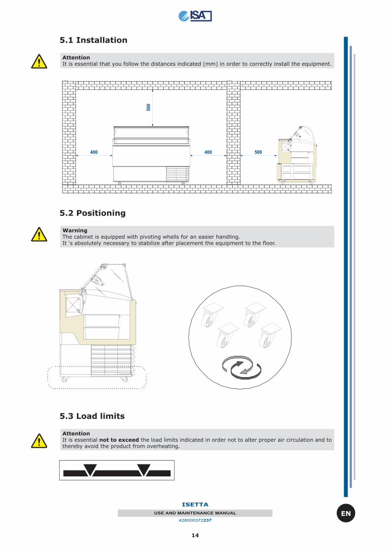
5.1 Installation
AttentionIt is essential that you follow the distances indicated (mm) in order to correctly install the equipment.
5.3 Load limits
AttentionIt is essential not to exceed the load limits indicated in order not to alter proper air circulation and to thereby avoid the product from overheating.
aaaaaaaaaaaaaaaaaaaaaaaaaaaaaaaaaaaaaaaaaaaaaaaaaaaaaaaaaaaaaa
aaaaaaaaaaaaaaaaaaaaaaaaaaaaaaaaaaaaaaaaaaaaaaaaaaaaaaaaaaaa
aaaaaaaaaaaaaaaaaaaaaaaaaaaaaaaaaaaaaaaaaaaaaaaaaaaaaaaaaaaaaaaaaaaaaaaaaaaaaaaaaaaaaaaaaaaaaaaaaaaaaaaaaaaaaaaaaaaaaaaaaaaaaaaaaaaaaaaaaaaaaaaaaaaaaaaaaaaaaaaaaa
aaaaaaaaaaaaaaaaaaaaaaaaaaaaaaaaaaaa
5.2 Positioning
WarningThe cabinet is equipped with pivoting whells for an easier handling.It ‘s absolutely necessary to stabilize after placement the equipment to the fl oor.
15
ISETTA
USE AND MAINTENANCE MANUAL
428000372237
EN
6. EQUIPMENT DESCRIPTION
6.1 Assembled structure
The equipment comprises a single furniture on which all the functional devices needed to make it a professional product effi cient for its intended use are assembled.
The equipment comprises:
- Insulated structure in ecological polyurethane- Cooling system- Electronic control panel- Electrical system- Built-in hermetic condensing unit- Lighting- Rear pivoting methacrilate panel system on operator side- 4 pivoting whells
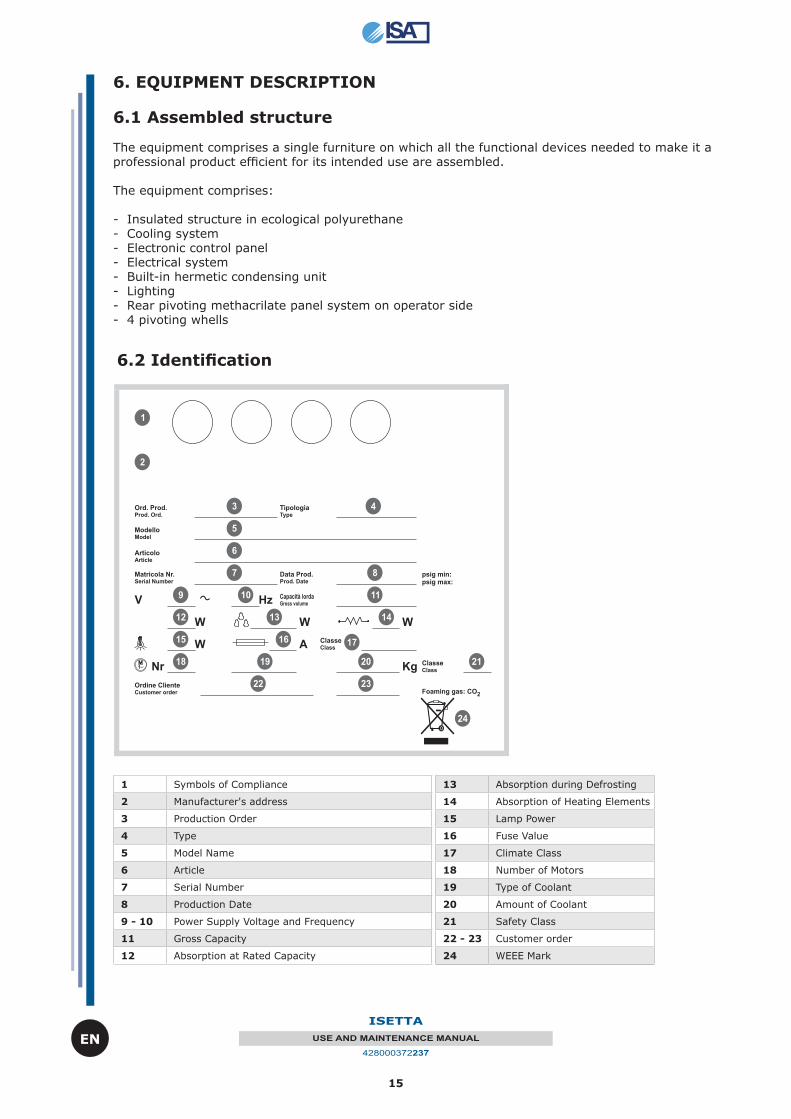
6.2 Identifi cation
1 Symbols of Compliance
2 Manufacturer's address
3 Production Order
4 Type
5 Model Name
6 Article
7 Serial Number
8 Production Date
9 - 10 Power Supply Voltage and Frequency
11 Gross Capacity
12 Absorption at Rated Capacity
13 Absorption during Defrosting
14 Absorption of Heating Elements
15 Lamp Power
16 Fuse Value
17 Climate Class
18 Number of Motors
19 Type of Coolant
20 Amount of Coolant
21 Safety Class
22 - 23 Customer order
24 WEEE Mark
16
ISETTA
USE AND MAINTENANCE MANUAL
428000372237
EN
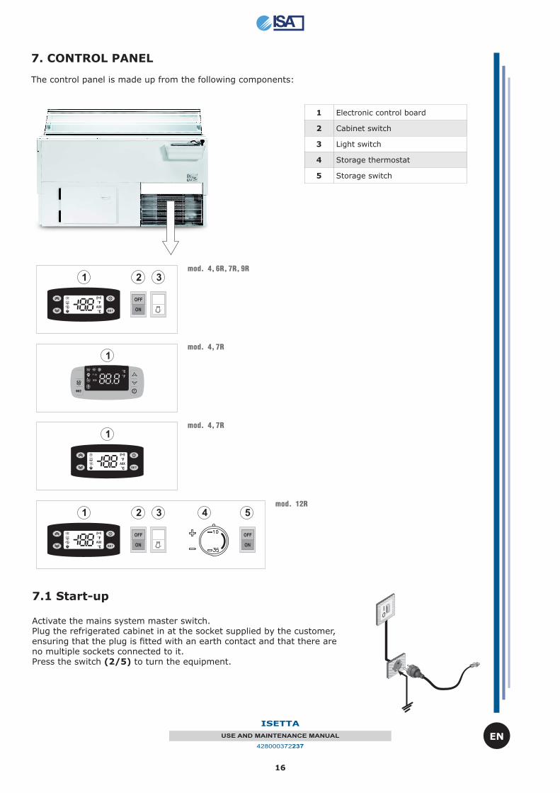
1 Electronic control board
2 Cabinet switch
3 Light switch
4 Storage thermostat
5 Storage switch
7. CONTROL PANEL The control panel is made up from the following components:
7.1 Start-up
Activate the mains system master switch. Plug the refrigerated cabinet in at the socket supplied by the customer, ensuring that the plug is fi tted with an earth contact and that there are no multiple sockets connected to it. Press the switch (2/5) to turn the equipment.
17
ISETTA
USE AND MAINTENANCE MANUAL
428000372237
EN
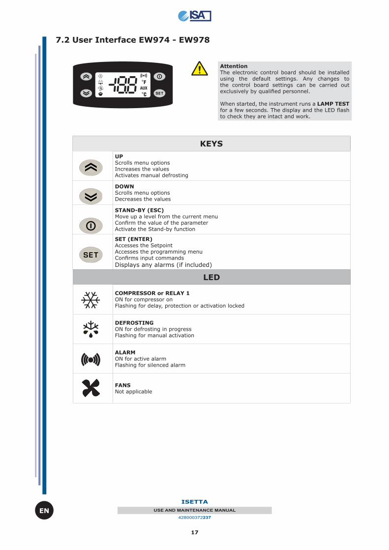
KEYS
UP Scrolls menu optionsIncreases the valuesActivates manual defrosting
DOWN Scrolls menu optionsDecreases the values
STAND-BY (ESC) Move up a level from the current menuConfi rm the value of the parameterActivate the Stand-by function
SET (ENTER) Accesses the SetpointAccesses the programming menuConfi rms input commands
Displays any alarms (if included)
AttentionThe electronic control board should be installed using the default settings. Any changes to the control board settings can be carried out exclusively by qualifi ed personnel.
When started, the instrument runs a LAMP TEST for a few seconds. The display and the LED fl ash to check they are intact and work.
7.2 User Interface EW974 - EW978
LED
COMPRESSOR or RELAY 1 ON for compressor onFlashing for delay, protection or activation locked
DEFROSTING ON for defrosting in progressFlashing for manual activation
ALARM ON for active alarmFlashing for silenced alarm
FANS Not applicable
18
ISETTA
USE AND MAINTENANCE MANUAL
428000372237
EN
SET Button
Press the SET (ENTER) button and release immediately.The label “Set” will appear.To view the Setpoint value, press the SET (ENTER) again.The Setpoint value will appear on the display.To change the Setpoint value, press the UP and DOWN buttons within 15 seconds.To confi rm the new programmed Setpoint value, press the SET (ENTER) button again.If you do not push any buttons for more than 15 seconds (time-out) or press the STAND-BY (ESC) button once, the last value displayed on the monitor is confi rmed and the program returns to the previous page.
Check UP
The alarm condition is always signalled by the buzzer (if installed) and by the LED next to the alarm icon. The alarm signal due to a faulty probe (probe 1) appears directly on the display of the instrument with the indication E1.The alarm signal due to a faulty evaporator (probe 2) appears directly on the display of the instrument with the indication E2.
Manual activation of the Defrosting cycle
The defrosting cycle is manually activated by keeping the UP button pressed for 5 seconds.If the conditions for a defrosting cycle are not right (e.g. temperature od the evaporator probe is higher than the temperature at the end of the defrosting cycle) the display will fl ash three (3) times to signal that the operation will not be performed.
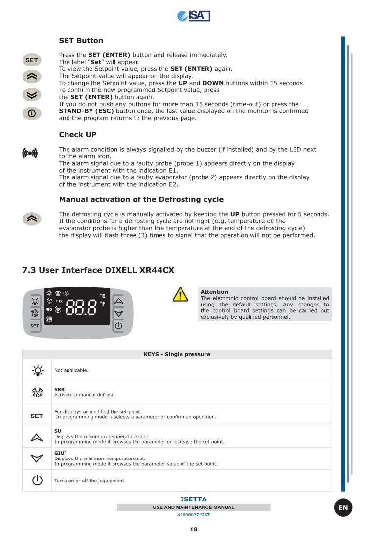
KEYS - Single pressure
Not applicable.
SBRActivate a manual defrost.
For displays or modifi ed the set-point. In programming mode it selects a parameter or confi rm an operation.
SUDisplays the maximum temperature set.In programming mode it browses the parameter or increase the set point.
GIU’Displays the minimum temperature set.In programming mode it browses the parameter value of the set-point.
Turns on or off the ‘equipment.
7.3 User Interface DIXELL XR44CX
AttentionThe electronic control board should be installed using the default settings. Any changes to the control board settings can be carried out exclusively by qualifi ed personnel.
19
ISETTA
USE AND MAINTENANCE MANUAL
428000372237
EN
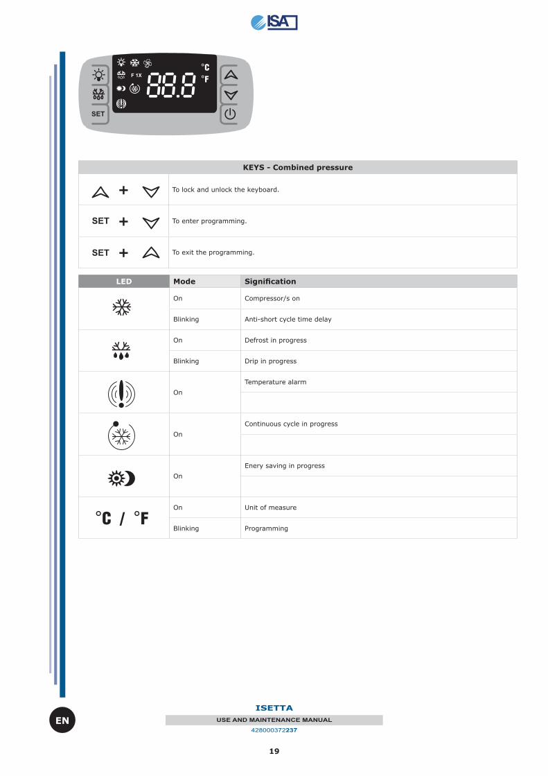
KEYS - Combined pressure
+ To lock and unlock the keyboard.
+ To enter programming.
+ To exit the programming.
LED Mode Signifi cation
On Compressor/s on
Blinking Anti-short cycle time delay
On Defrost in progress
Blinking Drip in progress
On
Temperature alarm
On
Continuous cycle in progress
On
Enery saving in progress
On Unit of measure
Blinking Programming
20
ISETTA
USE AND MAINTENANCE MANUAL
428000372237
EN
8. ROUTINE MAINTENANCE and REGULAR CHECKS
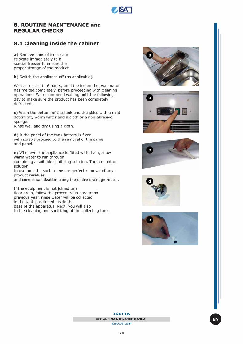
8.1 Cleaning inside the cabinet
a) Remove pans of ice creamrelocate immediately to aspecial freezer to ensure theproper storage of the product.
b) Switch the appliance off (as applicable).
Wait at least 4 to 6 hours, until the ice on the evaporator
has melted completely, before proceeding with cleaning
operations. We recommend waiting until the following
day to make sure the product has been completely
defrosted.
c) Wash the bottom of the tank and the sides with a mild
detergent, warm water and a cloth or a non-abrasive
sponge.
Rinse well and dry using a cloth.
d) If the panel of the tank bottom is fi xedwith screws proceed to the removal of the sameand panel.
e) Whenever the appliance is fi tted with drain, allow
warm water to run through
containing a suitable sanitizing solution. The amount of
solution
to use must be such to ensure perfect removal of any
product residues
and correct sanitization along the entire drainage route..
If the equipment is not joined to afl oor drain, follow the procedure in paragraphprevious year. rinse water will be collectedin the tank positioned inside thebase of the apparatus. Next, you will alsoto the cleaning and sanitizing of the collecting tank.
a
b
c
d
e
21
ISETTA
USE AND MAINTENANCE MANUAL
428000372237
EN
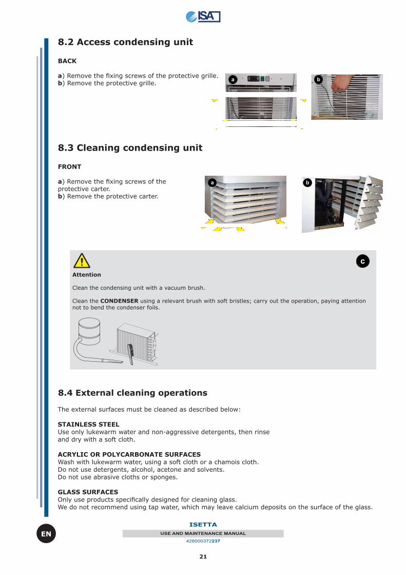
8.2 Access condensing unit
BACK
a) Remove the fi xing screws of the protective grille.b) Remove the protective grille.
8.3 Cleaning condensing unit
FRONT
a) Remove the fi xing screws of the protective carter.b) Remove the protective carter.
a b
a b
Attention
Clean the condensing unit with a vacuum brush.
Clean the CONDENSER using a relevant brush with soft bristles; carry out the operation, paying attention not to bend the condenser foils.
c
8.4 External cleaning operations
The external surfaces must be cleaned as described below:
STAINLESS STEEL
Use only lukewarm water and non-aggressive detergents, then rinse
and dry with a soft cloth.
ACRYLIC OR POLYCARBONATE SURFACES
Wash with lukewarm water, using a soft cloth or a chamois cloth.
Do not use detergents, alcohol, acetone and solvents.
Do not use abrasive cloths or sponges.
GLASS SURFACES
Only use products specifi cally designed for cleaning glass.
We do not recommend using tap water, which may leave calcium deposits on the surface of the glass.
22
ISETTA
USE AND MAINTENANCE MANUAL
428000372237
EN
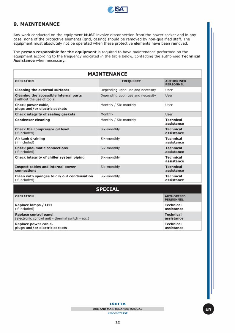
Any work conducted on the equipment MUST involve disconnection from the power socket and in any case, none of the protective elements (grid, casing) should be removed by non-qualifi ed staff. The equipment must absolutely not be operated when these protective elements have been removed.
The person responsible for the equipment is required to have maintenance performed on the equipment according to the frequency indicated in the table below, contacting the authorised Technical Assistance when necessary.
9. MAINTENANCE
MAINTENANCE
OPERATION FREQUENCY AUTHORISED PERSONNEL
Cleaning the external surfaces Depending upon use and necessity User
Cleaning the accessible internal parts (without the use of tools)
Depending upon use and necessity User
Check power cable, plugs and/or electric sockets
Monthly / Six-monthly User
Check integrity of sealing gaskets Monthly User
Condenser cleaning Monthly / Six-monthly Technical assistance
Check the compressor oil level(if included)
Six-monthly Technical assistance
Air tank draining(if included)
Six-monthly Technical assistance
Check pneumatic connections(if included)
Six-monthly Technical assistance
Check integrity of chiller system piping Six-monthly Technical assistance
Inspect cables and internal power connections
Six-monthly Technical assistance
Clean with sponges to dry out condensation(if included)
Six-monthly Technical assistance
SPECIAL
OPERATION AUTHORISED PERSONNEL
Replace lamps / LED (if included)
Technical assistance
Replace control panel(electronic control unit - thermal switch - etc.)
Technical assistance
Replace power cable,plugs and/or electric sockets
Technical assistance
23
ISETTA
USE AND MAINTENANCE MANUAL
428000372237
EN
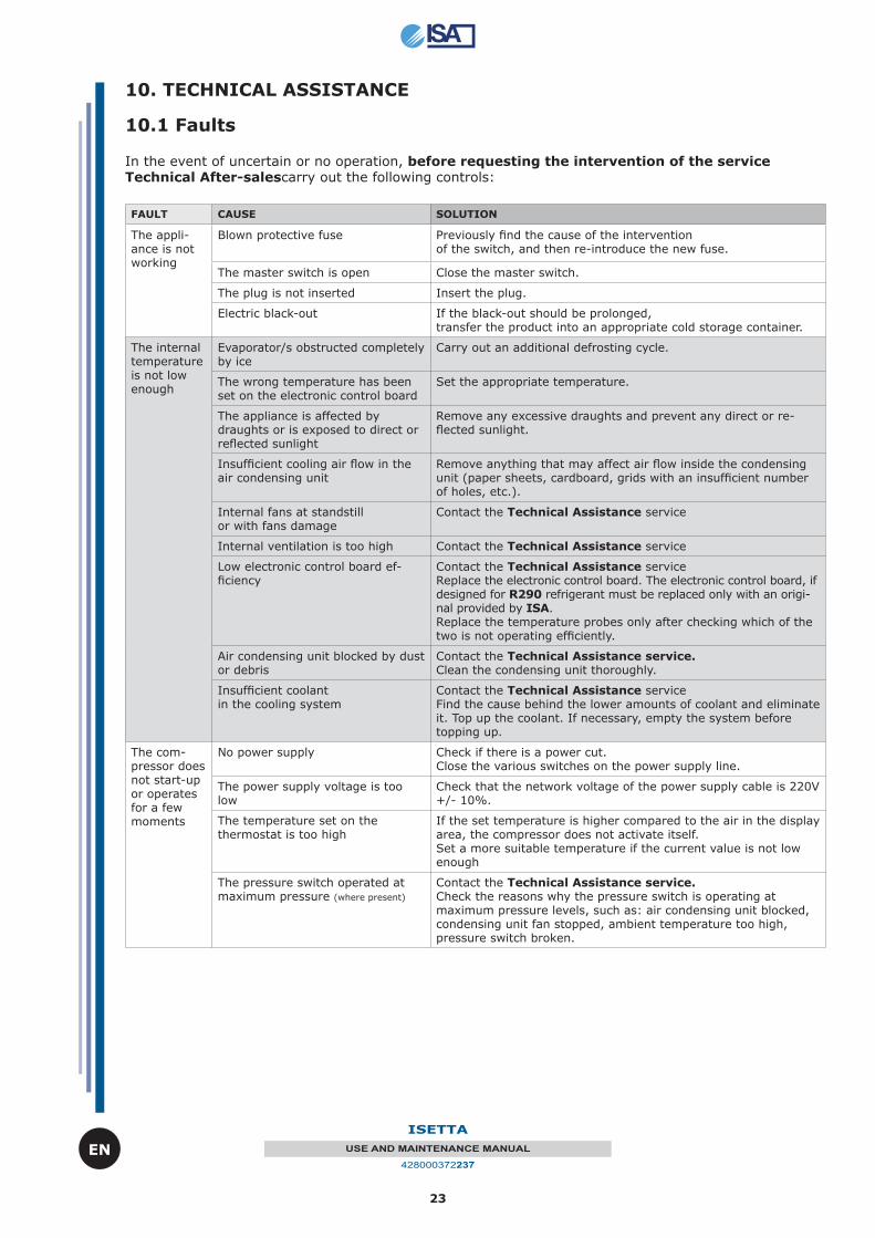
In the event of uncertain or no operation, before requesting the intervention of the service Technical After-salescarry out the following controls:
FAULT CAUSE SOLUTION
The appli-ance is not working
Blown protective fuse Previously fi nd the cause of the intervention of the switch, and then re-introduce the new fuse.
The master switch is open Close the master switch.
The plug is not inserted Insert the plug.
Electric black-out If the black-out should be prolonged, transfer the product into an appropriate cold storage container.
The internal temperature is not low enough
Evaporator/s obstructed completely by ice
Carry out an additional defrosting cycle.
The wrong temperature has been set on the electronic control board
Set the appropriate temperature.
The appliance is affected by draughts or is exposed to direct or refl ected sunlight
Remove any excessive draughts and prevent any direct or re-fl ected sunlight.
Insuffi cient cooling air fl ow in the air condensing unit
Remove anything that may affect air fl ow inside the condensing unit (paper sheets, cardboard, grids with an insuffi cient number of holes, etc.).
Internal fans at standstill or with fans damage
Contact the Technical Assistance service
Internal ventilation is too high Contact the Technical Assistance service
Low electronic control board ef-fi ciency
Contact the Technical Assistance serviceReplace the electronic control board. The electronic control board, if designed for R290 refrigerant must be replaced only with an origi-nal provided by ISA.Replace the temperature probes only after checking which of the two is not operating effi ciently.
Air condensing unit blocked by dust or debris
Contact the Technical Assistance service. Clean the condensing unit thoroughly.
Insuffi cient coolantin the cooling system
Contact the Technical Assistance serviceFind the cause behind the lower amounts of coolant and eliminate it. Top up the coolant. If necessary, empty the system before topping up.
The com-pressor does not start-up or operates for a few moments
No power supply Check if there is a power cut.Close the various switches on the power supply line.
The power supply voltage is too low
Check that the network voltage of the power supply cable is 220V +/- 10%.
The temperature set on thethermostat is too high
If the set temperature is higher compared to the air in the display area, the compressor does not activate itself.Set a more suitable temperature if the current value is not low enough
The pressure switch operated at maximum pressure (where present)
Contact the Technical Assistance service. Check the reasons why the pressure switch is operating at maximum pressure levels, such as: air condensing unit blocked, condensing unit fan stopped, ambient temperature too high, pressure switch broken.
10. TECHNICAL ASSISTANCE
10.1 Faults
24
ISETTA
USE AND MAINTENANCE MANUAL
428000372237
EN
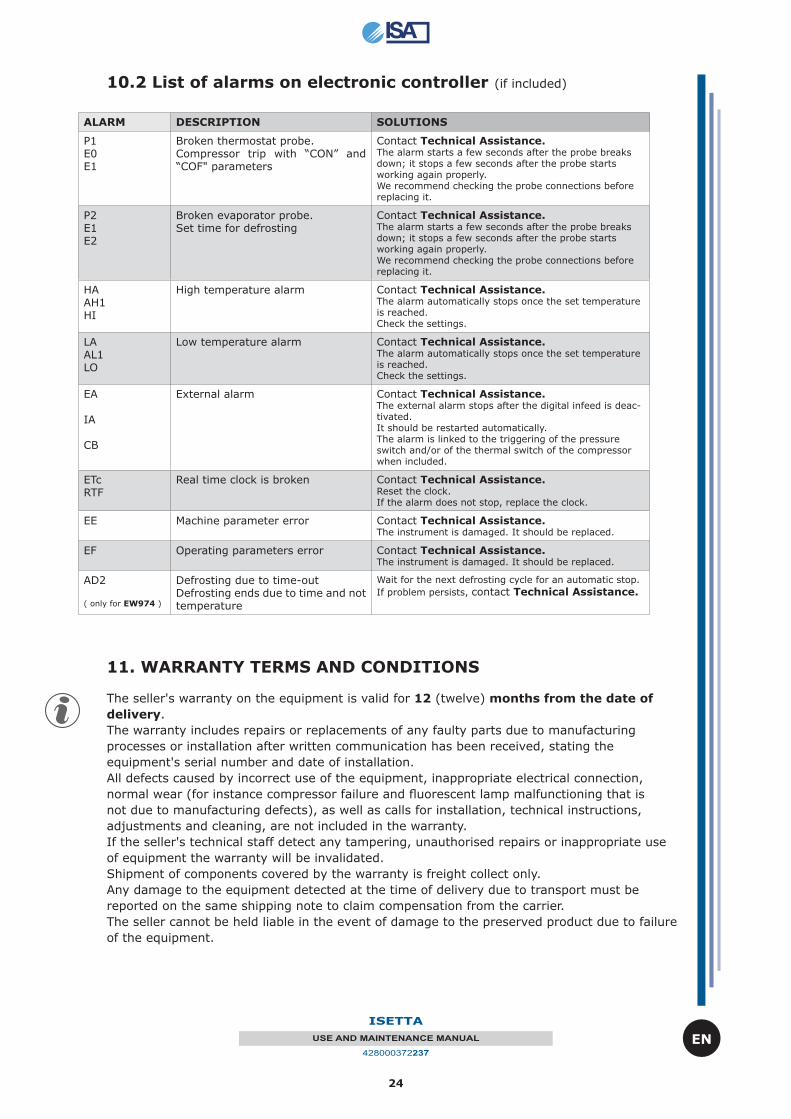
10.2 List of alarms on electronic controller (if included)
ALARM DESCRIPTION SOLUTIONS
P1E0E1
Broken thermostat probe. Compressor trip with “CON” and “COF" parameters
Contact Technical Assistance. The alarm starts a few seconds after the probe breaks down; it stops a few seconds after the probe starts working again properly. We recommend checking the probe connections before replacing it.
P2E1E2
Broken evaporator probe. Set time for defrosting
Contact Technical Assistance. The alarm starts a few seconds after the probe breaks down; it stops a few seconds after the probe starts working again properly. We recommend checking the probe connections before replacing it.
HAAH1HI
High temperature alarm Contact Technical Assistance. The alarm automatically stops once the set temperature is reached. Check the settings.
LAAL1LO
Low temperature alarm Contact Technical Assistance. The alarm automatically stops once the set temperature is reached. Check the settings.
EA
IA
CB
External alarm Contact Technical Assistance. The external alarm stops after the digital infeed is deac-tivated. It should be restarted automatically. The alarm is linked to the triggering of the pressure switch and/or of the thermal switch of the compressor when included.
ETcRTF
Real time clock is broken Contact Technical Assistance. Reset the clock. If the alarm does not stop, replace the clock.
EE Machine parameter error Contact Technical Assistance. The instrument is damaged. It should be replaced.
EF Operating parameters error Contact Technical Assistance. The instrument is damaged. It should be replaced.
AD2
( only for EW974 )
Defrosting due to time-outDefrosting ends due to time and not temperature
Wait for the next defrosting cycle for an automatic stop.
If problem persists, contact Technical Assistance.
11. WARRANTY TERMS AND CONDITIONS
The seller's warranty on the equipment is valid for 12 (twelve) months from the date of
delivery.
The warranty includes repairs or replacements of any faulty parts due to manufacturing
processes or installation after written communication has been received, stating the
equipment's serial number and date of installation.
All defects caused by incorrect use of the equipment, inappropriate electrical connection,
normal wear (for instance compressor failure and fl uorescent lamp malfunctioning that is
not due to manufacturing defects), as well as calls for installation, technical instructions,
adjustments and cleaning, are not included in the warranty.
If the seller's technical staff detect any tampering, unauthorised repairs or inappropriate use
of equipment the warranty will be invalidated.
Shipment of components covered by the warranty is freight collect only.
Any damage to the equipment detected at the time of delivery due to transport must be
reported on the same shipping note to claim compensation from the carrier.
The seller cannot be held liable in the event of damage to the preserved product due to failure
of the equipment.
25
ISETTA
USE AND MAINTENANCE MANUAL
428000372237
EN
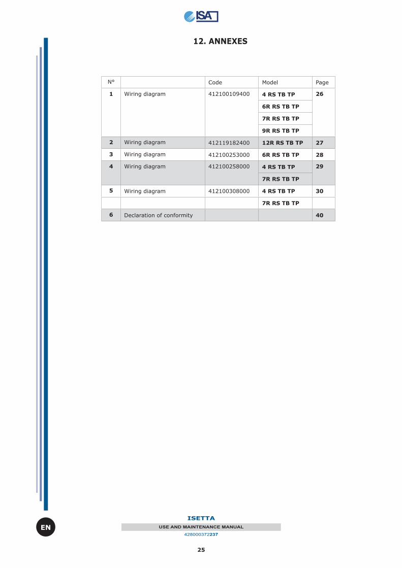
12. ANNEXES
N° Code Model Page
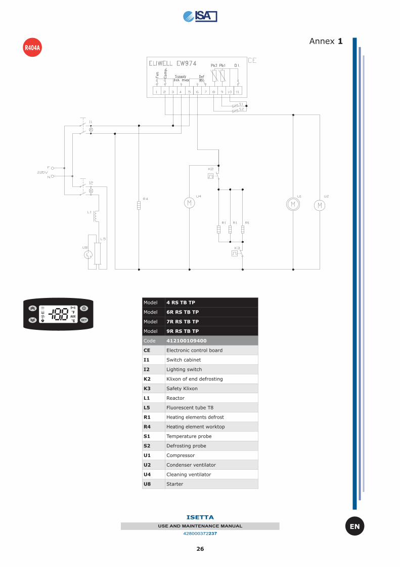
1 Wiring diagram 412100109400 4 RS TB TP 26
6R RS TB TP
7R RS TB TP
9R RS TB TP
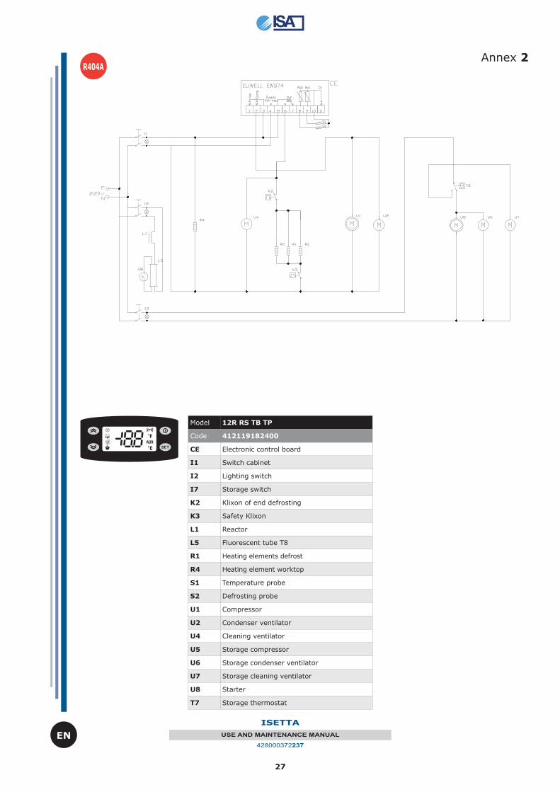
2 Wiring diagram 412119182400 12R RS TB TP 27
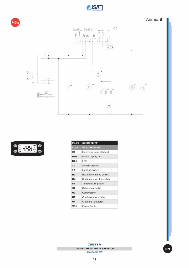
3 Wiring diagram 412100253000 6R RS TB TP 28
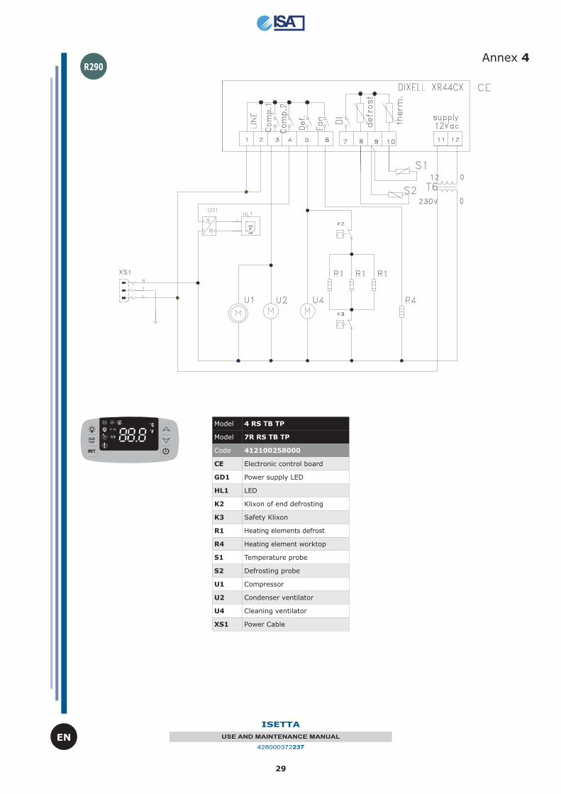
4 Wiring diagram 412100258000 4 RS TB TP 29
7R RS TB TP
5 Wiring diagram 412100308000 4 RS TB TP 30
7R RS TB TP
6 Declaration of conformity 40
26
ISETTA
USE AND MAINTENANCE MANUAL
428000372237
EN
Annex 1
Model 4 RS TB TP
Model 6R RS TB TP
Model 7R RS TB TP
Model 9R RS TB TP
Code 412100109400
CE Electronic control board
I1 Switch cabinet
I2 Lighting switch
K2 Klixon of end defrosting
K3 Safety Klixon
L1 Reactor
L5 Fluorescent tube T8
R1 Heating elements defrost
R4 Heating element worktop
S1 Temperature probe
S2 Defrosting probe
U1 Compressor
U2 Condenser ventilator
U4 Cleaning ventilator
U8 Starter
R404A
27
ISETTA
USE AND MAINTENANCE MANUAL
428000372237
EN
Annex 2
Model 12R RS TB TP
Code 412119182400
CE Electronic control board
I1 Switch cabinet
I2 Lighting switch
I7 Storage switch
K2 Klixon of end defrosting
K3 Safety Klixon
L1 Reactor
L5 Fluorescent tube T8
R1 Heating elements defrost
R4 Heating element worktop
S1 Temperature probe
S2 Defrosting probe
U1 Compressor
U2 Condenser ventilator
U4 Cleaning ventilator
U5 Storage compressor
U6 Storage condenser ventilator
U7 Storage cleaning ventilator
U8 Starter
T7 Storage thermostat
R404A
28
ISETTA
USE AND MAINTENANCE MANUAL
428000372237
EN
Annex 3R404A
Model 6R RS TB TP
Code 412100253000
CE Electronic control board
GD1 Power supply LED
HL1 LED
I1 Switch cabinet
I2 Lighting switch
R1 Heating elements defrost
R4 Heating element worktop
S1 Temperature probe
S2 Defrosting probe
U1 Compressor
U2 Condenser ventilator
U4 Cleaning ventilator
XS1 Power Cable
29
ISETTA
USE AND MAINTENANCE MANUAL
428000372237
EN
Annex 4R290
Model 4 RS TB TP
Model 7R RS TB TP
Code 412100258000
CE Electronic control board
GD1 Power supply LED
HL1 LED
K2 Klixon of end defrosting
K3 Safety Klixon
R1 Heating elements defrost
R4 Heating element worktop
S1 Temperature probe
S2 Defrosting probe
U1 Compressor
U2 Condenser ventilator
U4 Cleaning ventilator
XS1 Power Cable
30
ISETTA
USE AND MAINTENANCE MANUAL
428000372237
EN
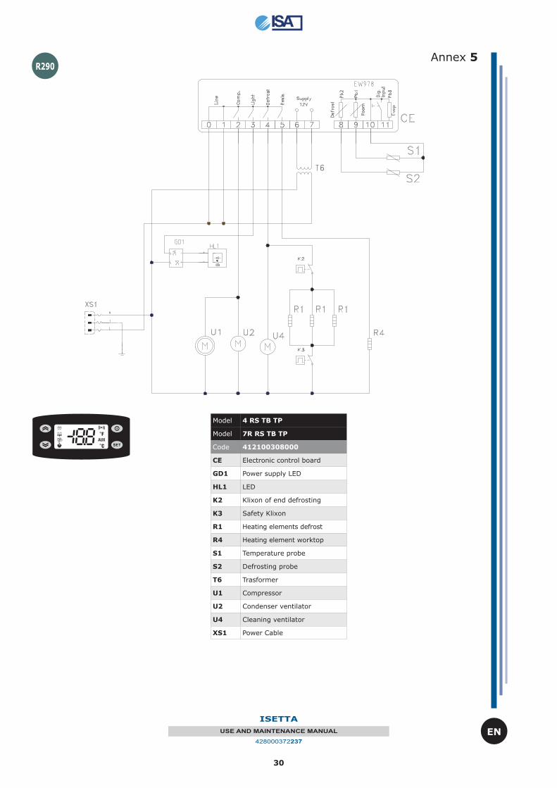
R290 Annex 5
Model 4 RS TB TP
Model 7R RS TB TP
Code 412100308000
CE Electronic control board
GD1 Power supply LED
HL1 LED
K2 Klixon of end defrosting
K3 Safety Klixon
R1 Heating elements defrost
R4 Heating element worktop
S1 Temperature probe
S2 Defrosting probe
T6 Trasformer
U1 Compressor
U2 Condenser ventilator
U4 Cleaning ventilator
XS1 Power Cable
31
ISETTA
USE AND MAINTENANCE MANUAL
428000372237
EN
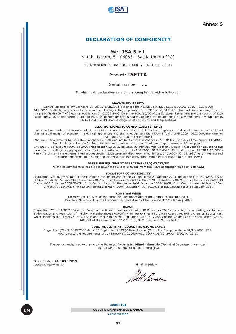
Annex 6
DECLARATION OF CONFORMITY
We: ISA S.r.l. Via del Lavoro, 5 - 06083 - Bastia Umbra (PG)
declare under our own responsibility, that the product:
Product: ISETTA
Serial number: .....
To which this declaration refers, is in compliance with e following:
MACHINERY SAFETY General electric safety Standard EN 60335-1/Ed.2002+Modifi cations A11:2004,A1:2004,A12:2006,A2:2006 + A13:2008
A15:2011. Particular requirements for commercial refrigerating appliances EN 60335-2-89/Ed.2010. Standard for Measuring Electro-magnetic Fields (EMF) of Electrical Appliances EN 62233:2008, Directive 2006/95/EC of the European Parliament and the Council of 12th December 2006 on the harmonisation of the Laws of Member States relating to electrical equipment for use within certain voltage limits
EN 62471/Ed.2009 Photo-biologic safety of lamps and lamp systems
ELECTROMAGNETIC COMPATIBILITY (EMC)Limits and methods of measurement of radio interference characteristics of household appliances and similar motor-operated and thermal appliances, of equipment, electrical appliances and similar equipment EN 55014-1 (valid until 2009: Ed.2000+Amendments
A1:2001, A2:2002 - or: Ed.2006) Minimum requirements for household appliances, tools and similar electrical appliances EN 55014-2 (Ed.1997+Amendment A1:2001)
Part 3: Limits – Section 2: Limits for harmonic current emissions (equipment input current=16A per phase) EN61000-3-2 (valid until 2009:Ed.2000+Modifi cation A2:2005-or:Ed.2006) Part 3:Limits-Section 3:Limitation of voltage fl uctuations and fl icker in low-voltage supply systems for equipment with rated current=16A EN61000-3-3 (Ed.1995+Modifi cations A1:2001,A2:2005) Part 4:Testing and measurement techniques Section 2:Electrostatic discharge immunity test EN61000-4-2 (Ed.1995) Part 4:Testing and
measurement techniques Section 4: Electrical fast transient/burst immunity test EN61000-4-4 (Ed.1995)
PRESSURE EQUIPMENT DIRECTIVE (PED) 97/23/EC As the equipment falls into a class lower than I, it is excluded from the PED’s application fi eld (art.1 par.3.6)
FOODSTUFF COMPATIBILITYRegulation (CE) N.1935/2004 of the European Parliament and of the Council dated 27 October 2004 Regulation (CE) N.2023/2006 of the Council dated 22 December, Directive 2008/39/CE of the Council dated 6 March 2008 Directive 2007/19/CE of the Council dated 30 March 2007 Directive 2005/79/CE of the Council dated 18 November 2005 Directive 2004/19/CE of the Council dated 10 March 2004
Directive 2004/1/CE of the Council dated 6 January 2004 Regulation (UE) 10/2011 of the Council dated 14 January 2011
ROHS and WEEE Directive 2011/95/EC of the European Parliament and of the Council of 8th June 2011
Directive 2002/96/EC of the European Parliament and of the Council of 27th January 2003
REACH Regulation (CE) n. 1907/2006 of the European parliament and council dated 18 December 2006 concerning the recording, evaluation, authorisation and restriction of the chemical substances (REACH), which establishes a European Agency regarding chemical substances, which modifi es the Directive 1999/45/CE and that repeals the Regulation (CEE) n. 793/93 of the Council and the regulation (CE) n.
1488/94 of the Commission 91/155/CEE, 93/105/CE and 2000/21/CE
SUBSTANCES THAT REDUCE THE OZONE LAYER Regulation (CE) N. 1005/2009 dated 16 September 2009 (Offi cial Journal (OJ) of the European Union 31/10/2009 L286)
According to the requirements set by Directives: 2006/95/EC, 2004/108/EC, 2006/42/EC, 97/23/EC
The person authorised to draw-up the Technical Folder is Mr. Minelli Maurizio (Technical Department Manager)Via del Lavoro 5 - 06083 Bastia Umbra (PG)
Bastia Umbra: 20 / 03 / 2015(place and date of issue) Minelli Maurizio