Embed Size (px)
Citation preview

(Revised 11/16/20) 401S - 1 STRUCTURAL EXCAVATION AND BACKFILL
ITEM NO. 401S - STRUCTURAL EXCAVATION AND BACKFILL
401S.1 - Description
This item shall govern the excavation for placement of structures, except pipe sewers, the disposal of
such excavated material and the backfill around completed structures to the level of the original ground or
grade indicated on the Drawings. The work shall include all necessary pumping or bailing, sheathing,
drainage, and the construction and removal of any required cofferdams. Unless otherwise indicated on
the Drawings, the work included hereunder shall provide for the removal of old structures or portions
thereof (abutments, buildings, foundations, wingwalls, piers, etc.), trees and all other obstructions
necessary to the proposed construction.
Where excavation is not classified, it will be grouped under "Unclassified Structural Excavation", which
shall include the removal of all materials encountered regardless of their nature or the manner in which
they are removed.
Where excavation is classified, it shall be classed as "Common Structural Excavation" or "Rock Structural
Excavation" in accordance with the following criteria:
"Common Structural Excavation" shall include the removal of all materials other than rock.
"Rock Structural Excavation" shall include the removal of firm and compact materials that cannot be
excavated with power equipment, without first being loosened or broken by blasting, sledging or drilling.
This specification is applicable for projects or work involving either inch-pound or SI units. Within the text
and accompanying tables, the inch-pound units are given preference followed by SI units shown within
parentheses.
401S.2 - Submittals
Within 14 days prior to the commencement of related work, the Contractor shall submit electronically the
following submittal requirements as applicable:
a. Supplier and certified test results for fine aggregate/sand material
b. Supplier and certified test results for flexible base material
c. Mix design and test results for lime stabilized subgrade material
d. Mix design and test results for Class J Concrete Base
e. Supplier and certified test results for granular material (coarse aggregate, foundation rock and
pea gravel)
f. Mix design and test results for cement-stabilized backfill
g. Mix design and test results for controlled low strength material (CLSM)
h. Excavation Safety System Plan for proposed cofferdams, trench excavation and special shoring
installations

(Revised 11/16/20) 401S - 2 STRUCTURAL EXCAVATION AND BACKFILL
401S.3 - Materials
A. Flexible Base
Flexible base shall conform to the requirements of Standard Specification Item No. 210S, "Flexible
Base".
B. Lime Stabilized Base
Lime stabilized base shall conform to the requirements of Standard Specification Item No. 202S,
"Lime" and Item No. 203S, "Lime Treatment for Materials in Place".
C. Concrete Base
Concrete base shall conform to a Class J Concrete as defined in Standard Specification Item
No. 403S, "Concrete for Structures".
D. Granular Material
1. Coarse aggregate shall conform to the requirements of section 403S.3.C of Standard
Specification Item No. 403S "Concrete for Structures".
2. Foundation Rock
Foundation rock shall be well graded, hard, durable coarse aggregate ranging in size from
2 to 6 inches.
E. Cement Stabilized Backfill
Cement stabilized backfill shall contain aggregate, water and a minimum of 7% hydraulic cement
based on the dry weight of the aggregate in accordance with TxDOT Test Method Tex-120-E, "Soil-
Cement Testing.” Unless directed otherwise on the Drawings, the aggregate shall be clean sand
approved by the City Engineer or designated representative.
F. Controlled Low Strength Material
Controlled low strength material (CLSM) shall conform to Standard Specification Item No. 402S,
"Controlled Low Strength Material" and shall be approved by the City Engineer or designated
representative.

(Revised 11/16/20) 401S - 3 STRUCTURAL EXCAVATION AND BACKFILL
401S.4 - Construction Methods
A. Erosion Control and Tree Protection
Prior to commencement of this work, all required erosion control and tree protection measures
indicated in the City of Pflugerville Tree Technical Manual: Standards & Specifications and/or on the
Drawings shall be in place. The existing utilities shall be located and protected as specified in the
City of Pflugerville Engineering Design Manual and Construction Standards and/or indicated on the
Drawings. A permit shall be required when utility adjustments are to be made in preparation for
construction in the right-of-way.
Areas within the construction limits indicated on the Drawings shall be cleared of all trees, stumps,
brush, etc., except trees or shrubs scheduled for preservation which shall be carefully trimmed as
directed by the City Engineer or designated representative, in accordance with the City of Pflugerville
Tree Technical Manual: Standards and Specifications and shall be protected from scarring, barking
or other injuries during construction operations. All exposed cuts over 2 inches in diameter, exposed
ends of pruned limbs or scarred bark shall be treated with an approved asphalt material within 24
hours of the pruning or injury.
Construction equipment shall not be operated, nor construction materials stockpiled under the
canopies of trees, unless otherwise indicated on the Drawings and/or specified in the Contract
Documents. Excavation or embankment materials shall not be placed within the drip line of trees
until tree wells are constructed.
Within the construction limits or areas indicated, all obstructions, stumps, roots, vegetation,
abandoned structures, rubbish and objectionable material shall be removed to the following depths:
1. In areas to receive 6 inches or more embankment, a minimum of 12 inches below natural
ground.
2. In areas to receive embankment less than 6 inches, a minimum of 18 inches below the lower
elevation of embankment, structure or excavation.
3. In areas to be excavated a minimum of 18 inches below the lower elevation of the
embankment, structure or excavation.
4. In all other areas a minimum of 12 inches below natural ground.
When abandoned storm drains, sewers or other drainage systems are encountered they shall be
removed as required to clear the new structure and plugged in a manner approved by the City
Engineer or designated representative.
Holes remaining after removal of all obstructions, objectionable material, trees, stumps, etc. shall be
backfilled with select embankment material and compacted by approved methods. All cleared and
grubbed material shall be disposed of in a manner satisfactory to the City Engineer or designated
representative. Unless otherwise provided, all materials as described above shall become the
property of the Contractor and removed from the site and disposed of at a permitted disposal site.
Burning materials at the site shall conform to City of Pflugerville Engineering Design Manual &
Construction Standards.
B. Excavation

(Revised 11/16/20) 401S - 4 STRUCTURAL EXCAVATION AND BACKFILL
1. Excavation shall be done in accordance with the lines and depths indicated on the Drawings
or as established by the City Engineer or designated representative. Unless otherwise
indicated on the Drawings or permitted by the City Engineer or designated representative no
excavation shall be made outside a vertical plane 3 feet from the footing lines and parallel
thereto. When caissons are provided, no excavation will be permitted outside the outer faces
of the caissons.
When structures are installed in streets, highways or other paved areas, the pavement and
base shall be cut to neat lines. After completion of the excavation and backfilling, the
pavement structure shall be restored to the satisfaction of the City Engineer or designated
representative.
2. Slopes, benching, sheeting, bracing, pumping and bailing shall be provided as necessary to
maintain the stability and safety of excavations up to 5 feet deep. Excavation protection for
excavations deeper than 5 feet shall be governed by Standard Specification Item No. 509S,
"Excavation Safety Systems".
3. Excavation shall conform to elevations indicated on the Drawing or raised or lowered by
written order of the City Engineer or designated representative, when such alterations are
judged proper. When it is deemed necessary to increase or decrease the plan depth of
footings, the alterations in the details of the structure shall be as directed by the City
Engineer or designated representative. The City Engineer or designated representative shall
have the right to substitute revised details resulting from consideration of changes in the
design conditions.
4. When a structure is to rest on an excavated surface other than rock, special care shall be
taken not to disturb the bottom of the excavation and the final excavation to grade shall not
be performed until just before the footing is placed. Equipment selected and used by the
Contractor for excavation which results in disturbance of what was otherwise stable
subgrade material, as shown by laboratory tests, will not be used as a justification for
payment for excavating to extra depth or for payment for stabilizing materials which may be
ordered by the City Engineer or designated representative.
5. Excavated material required to be used for backfill may be deposited by the Contractor in
storage piles as indicated on the Drawing or at points convenient for its rehandling during the
backfilling operations, subject to the approval of the City Engineer or designated
representative, who may require that the survey center line of the structure and the
transverse or hub line of any unit of the structure be kept free of any obstruction. The
Contractor shall adjust any stockpiles, to facilitate surveying and the work of other
Contractors working in the immediate proximity, as directed by the City Engineer or
designated representative.
6. Excavated material required to be wasted shall be disposed of as directed by the City
Engineer or designated representative, in a manner which will not obstruct the stream or
otherwise impair the efficiency or appearance of the structure or other part of the work.
7. For all single and multiple box culverts, pipe culverts, pipe arch culverts and box sewers of
all types, where the soil encountered at established footing grade is a quicksand, muck or
similar unstable material, the following procedure shall be used unless other methods are
indicated:

(Revised 11/16/20) 401S - 5 STRUCTURAL EXCAVATION AND BACKFILL
a. The depth to which unstable material is removed will be determined by the City
Engineer or designated representative. It will not exceed 2 feet below the footing of
culverts that are 2 feet or more in height and will not exceed the height of culverts for
those less than 2 feet high. Excavation shall be carried at least 1 foot horizontally
beyond the limits of the structure on all sides. All unstable soil removed shall be
replaced with suitable stable material, in uniform layers of suitable depth for compaction
as directed by the City Engineer or designated representative. Each layer shall be
wetted, if necessary and compacted by rolling or tamping as required to provide a
stable foundation for the structure. Soil, which has sufficient stability to properly sustain
the adjacent sections of the roadway embankment, will be considered a suitable
foundation material.
b. When, in the opinion of the City Engineer or designated representative, it is not feasible
to construct a stable footing as outlined above, the Contractor shall construct it by the
use of special materials, such as flexible base, cement stabilized base, cement
stabilized rockfill or other material, as directed by the City Engineer or designated
representative. This work will be paid for as provided in Section 401S.9, "Payment".
8. When the material encountered at footing grade of a culvert is found to be partially rock or
incompressible material and partially a compressible soil which is satisfactory for the
foundation, the incompressible material shall be removed for a depth of 6 inches below the
footing grade and backfilled with a compressible material similar to that used for the rest of
the structure.
401S.5 - Cofferdams
The term cofferdams, whenever used in this specification, designates any temporary or removable
structure constructed to hold the surrounding earth, water or both, out of the excavation, whether the
structure is formed of earth, timber, steel, concrete or a combination of these. It includes earthen dikes,
timber cribs, any type of sheet piling, removable steel shells and the like and all necessary bracing and it
shall be understood also to include the use of pumping wells or well points for de-watering. The cost of
cofferdams, when required, shall be included as a part of the bid price for excavation.
It is the intent of this specification to require that a suitable cofferdam be provided, when necessary, to
ensure that the foundation may be placed in a dry condition, as to preclude sliding and caving of the walls
of the excavation. The cofferdam shall conform with the requirements of Standard Specification Item
No. 509S, "Excavation Safety Systems" and shall provide a safe work area with sufficient clearance for
the construction, inspection and removal of required forms and, if necessary, sufficient room to allow
pumping outside the forms. Where no ground or surface water is encountered, the cofferdam need be
sufficient only to protect the workers and to avoid cave-ins or slides beyond the excavation limits.
Unless otherwise indicated on the Drawings, cofferdams shall be removed by the Contractor after the
completion of the substructure without disturbing or marring the structure.
401S.6 - De-Watering
Structures shall not be constructed or placed in the presence of water unless otherwise approved by the
City Engineer or designated representative. Precast members, pipe and concrete shall only be placed on
a dry, firm surface. Water shall be removed by bailing, pumping, well-point installation, deep wells,
underdrains or other approved method.

(Revised 11/16/20) 401S - 6 STRUCTURAL EXCAVATION AND BACKFILL
When structures are approved for placement in the presence of water, standing water shall be removed in
a manner that shall preclude the possibility of the movement of water through or alongside any concrete
being placed. Pumping or bailing will not be permitted during the placing of concrete or for a period of at
least 36 hours thereafter, unless from a suitable sump separated from the concrete work by a water-tight
wall.
Pumping or bailing during placement of seal concrete shall only be allowed to the extent necessary to
maintain a static head of water within the cofferdam. De-watering inside a sealed cofferdam shall not
commence until the seal has aged a minimum of 36 hours.
When the bottom of an excavation cannot be de-watered to the point that the subgrade is free of mud or it
is difficult to keep the reinforcing steel clean a stabilizing material (e.g. flexible base, cement-stabilized-
backfill or lean concrete) shall be placed in the bottom of the excavation. When a lean concrete is used,
the concrete shall include a minimum of 275 pounds of cement per cubic yard and be placed to a
minimum depth of 3 inches. Stabilizing material that is placed for the convenience of the Contractor will
be at the Contractor's own expense.
401S.7 - Backfilling
A. General
As soon as practicable, all portions of excavation not occupied by the permanent structure shall be
backfilled. Back-fill material shall be free from stones large enough to interfere with compaction,
large or frozen lumps that will not break down readily under compaction, wood or other extraneous
material. Backfill material shall be approved by the City Engineer or designated representative.
1. That portion of the backfill which will support any portion of the roadbed or embankment or is
within 2 feet of the roadbed or embankment shall be placed in uniform layers not to exceed
6 inches in depth (loose measurement) and each layer compacted to the density specified
for the appropriate material. Each layer of backfill material, if dry, shall be wetted uniformly
to the moisture content required to obtain the specified density and shall be compacted to
that density by means of mechanical tamps, except that the use of rolling equipment of the
type generally used in compacting embankments will be permitted on portions which are
accessible to such equipment. All portions of embankment too close to any portion of a
structure to permit compaction by the use of the blading and rolling equipment used on
adjoining sections of embankment, shall be placed and compacted in the same manner as
specified above for backfill material. These provisions require the mechanical compaction,
by means of either rolling equipment or mechanical tamps, of all backfill and embankment
adjoining the exterior walls and wingwalls of culverts. Unless otherwise provided by the
Plans or Special Conditions, hand tamping will not be accepted as an alternate for
mechanical compaction. As a general rule, material used in filling or backfilling the portions
described in this paragraph shall be an earth free of any appreciable amount of gravel or
stone particles more than four (4) inches in greatest dimension and of a gradation that
permits thorough compaction. The percentage of fines shall be sufficient to fill all voids and
insure a uniform and thoroughly compacted mass of proper density. When required by the
Plans or by written order of the City, cement stabilized material shall be used for backfilling.
2. All portions of fill and backfill described in the preceding paragraph shall be compacted to
the same density requirements specified for the adjoining sections of embankment in
accordance with the governing specifications. Where no embankment is involved on the

(Revised 11/16/20) 401S - 7 STRUCTURAL EXCAVATION AND BACKFILL
Project and no specifications therefor are included in the Contract, all backfill shall be
compacted to a density comparable with the adjacent undisturbed material.
3. That portion of backfill which will not support any portion of completed roadbed or
embankment shall be placed in layers not more than 10 inches in depth (loose
measurement) and shall be compacted to a density comparable with the adjacent
undisturbed material.
4. If the excavation has been made through a hard material resistant to erosion, the backfill
around piers and in front of abutments and wings may be ordered by the City Engineer or
designated representative to be of stone or lean concrete. Unless otherwise indicated on the
Drawings, such backfill shall be paid for as extra work.
5. All portions of embankment too close to any portion of a structure to permit compaction by
the use of the blading and rolling equipment used on adjoining sections of embankment,
shall be placed and compacted with mechanical tamps and rammers to avoid damage to the
structure.
These provisions require mechanical compaction by means of either rolling equipment or mechanical
tampers or rammers, of all backfill and embankment adjoining the barrels and wingwalls or culverts
and adjoining all sides of bridge abutments and retaining walls, regardless of whether or not such
embankment or backfill is above or below the original surface of the ground and regardless of
whether the excavation at structure site was performed conforming to Standard Specification Item
No.111S, "Excavation", this Item No. 401S, "Structural Excavation and Backfill", Standard
Specification Item No. 110S, "Street Excavation" or Standard Specification Item No. 120S, "Channel
Excavation". Unless otherwise indicated on the Drawings, hand tamping will not be accepted as an
alternate for mechanical compaction.
As a general rule, material used in filling or backfilling the portions described in this paragraph shall
be an earth, free of any appreciable amount of gravel or stone particles larger than 4 inches in
greater dimension and of a gradation that permits thorough compaction. When, in the opinion of the
City Engineer or designated representative, such material is not readily available, the use of rock or
gravel mixed with earth will be permitted, provided that no particles larger than 12 inches or smaller
than 6 inches may be used. The percentage of fines shall be sufficient to fill all voids and insure a
uniform and thoroughly compacted mass of proper density. When required by the Drawings or by
written order of the City Engineer or designated representative, cement-stabilized-backfill material
shall be used for backfilling.
All portions of fill and backfill described in the preceding paragraph shall be compacted to the same
density requirements specified for the adjoining sections of embankment in accordance with the
governing specifications. Where no embankment is involved on the project and no relevant
specifications are included in the contract, all backfill shall be compacted to a density comparable
with the adjacent undisturbed material.
No backfill shall be placed against any abutment or retaining wall until such structure has been in
place at least 7 days. No backfill shall be placed adjacent to or over single and multiple boxes until
the top slab has attained 500 psi flexural strength. Backfill placed around abutments and piers shall
be deposited on both sides to approximately the same elevation at the same time.

(Revised 11/16/20) 401S - 8 STRUCTURAL EXCAVATION AND BACKFILL
Care shall be taken to prevent any wedging action of backfill against the structure and the slopes
bounding the excavation shall be stepped or serrated to prevent such action. Backfill shall be
uniformly placed around bridge foundations.
Backfilling shall not proceed prior to inspection and approval of the inspector.
B. Pipe Culverts
The following requirements shall apply to the backfilling of pipe culverts in addition to the pertinent
portions of the general requirements given in the preceding section and in pipe bedding standards.
Selected materials from excavation, borrow or other approved material shall be wetted, if required
and placed along both sides of the pipe equally, in uniform layers not exceeding 10 inches in depth
(loose measurement) and thoroughly compacted so that there shall be a berm of thoroughly
compacted material on each side of the pipe. The method and degree of compaction shall be the
same as specified above for portions of backfill within the limits of embankment or roadbed.
Filling and/or backfilling shall be continued in this manner to the elevation of the top of the pipe.
Special care shall be taken to secure thorough compaction of the material placed under the
haunches of the pipe to prevent damage or displacement of the pipe. All fill or backfill below the top
of pipe shall be compacted mechanically in the manner and to the density prescribed above,
regardless of whether or not such material is placed within the limits of the embankment or roadbed.
In the case of pipe placed in trenches, that portion of the backfill above the top of the pipe which
supports embankment or the roadbed shall receive mechanical compaction as specified above and
the portion which will not support any portion of embankment or roadbed shall be placed in layers not
more than 10 inches in depth (loose measurement) and shall be compacted by whatever means the
Contractor chooses, to a density comparable with the adjacent, undisturbed material. Embankments
above the top of pipe shall be placed conforming to Item No. 132S, "Embankment". During
construction adequate cover must be provided to protect the structure from damage.
The City Engineer or designated representative may reject backfill material that contains more than
20% by weight of material retained on a 3-in sieve, with large lumps not easily broken down, or that
cannot be spread in loose layers. Material excavated by a trenching machine will generally meet the
requirements of this Section as long as large stones are not present.
Where pipe extends beyond the toe of slope of the embankment and the depth of cover provided by
backfill to the original ground level is less than the minimum required by the specifications for the
type of pipe involved, additional material shall be placed and compacted until the minimum cover has
been provided.
Whenever excavation is made for installing pipe culverts or box sewers across private property or
beyond the limits of the embankment, the top soil removed in excavating the trench shall be kept
separate and replaced as nearly as feasible in its original position and the entire area involved in the
construction operations shall be restored to a presentable condition.
C. Cement Stabilized Backfill
When indicated on the Drawings, trenches shall be backfilled to the elevations shown with cement
stabilized backfill. The cement-stabilized backfill shall be placed equally along the sides of structures
to prevent strain on or displacement of the structure.

(Revised 11/16/20) 401S - 9 STRUCTURAL EXCAVATION AND BACKFILL
Cement stabilized backfill below the spring line of pipe culverts shall be sufficiently plastic to
completely fill all voids in the trench. Hand operated tampers may be used if necessary to fill the
voids. The pipe shall be held in alignment by jacks or other suitable means to prevent the mortared
joints from cracking due to displacement caused by placing the backfill material.
Cement stabilized backfill above the spring line of pipe culverts may be dry enough to be transported
without special mixing equipment.
On structures other than pipe culverts, special mixing equipment will not be required to transport the
cement stabilized backfill unless otherwise indicated on the Drawings.
D. Controlled Low Strength Material (CLSM)
When indicated on the Drawings the excavation shall be backfilled with CLSM to the elevations
shown. The structure shall be prevented from being displaced or "floated out" during the placement
of CLSM. The CLSM shall be prevented from entering culverts and drainage structures.
401S.8 - Measurement
Unless otherwise indicated on the Drawings, structural excavation for pipe headwalls, inlets, manholes,
culvert widening (extensions), bridge abutments and side road and private entrance pipe culverts will not
be measured in the field but shall be included in the Plan Quantity unit price bid by the cubic yard.
Determination of plan quantities for structural excavation shall be made by the method of average end-
areas using the following limits to establish templates for measurement.
A. For all structures requiring measurement, except the barrels of pipe culverts, no material outside of
vertical planes 1 foot beyond the edges of the footings and parallel thereto will be included.
B. For the barrels of pipe culverts of 42 inches or less nominal or equivalent diameter, no material
outside of vertical planes 1 foot beyond the horizontal projection of the outside surfaces of the pipe
and parallel thereto will be included. For the barrels of pipe culverts more than 42 inches in nominal
or equivalent diameter, no material outside of vertical planes located 2 feet beyond the horizontal
projection of the outside surfaces of the pipe and parallel thereto will be included.
C. If a cofferdam, as herein defined, is used, the limitations indicated above shall apply just as if no
cofferdams were used.
D. Where excavation in addition to that allowed for the footings is required for other portions of the
structure, such as for the cap, cross strut or tie beam of a pier or bent or for the superstructure,
measurements for such additional excavation will be limited laterally by vertical planes 1 foot beyond
the face of the member and parallel thereto and vertically to a depth of 1 foot below the bottom of
such member.
E. Except as allowed by the above conditions, no account will be taken of any excavation necessary for
placing forms or falsework.
F. Except at side road culverts, all street excavation called for on the contract drawings at all structure
sites shall be assumed to be completed before starting the structural excavation and the
measurement of structural excavation will include only material below or outside the limits of the
completed street excavation. Excavation for side road and private entrance pipe culverts will not be
measured for payment but shall be included in the unit price bid for this specification item.

(Revised 11/16/20) 401S - 10 STRUCTURAL EXCAVATION AND BACKFILL
G. On all structures of bridge classification where the contract drawings call for channel excavation at
the structure site, it shall be assumed to have been completed before starting the structural
excavation and the measurement of structural excavation will include only material below or outside
the limits of the completed channel section. The method of measurement for payment will be in
accordance with this procedure regardless of the actual construction methods followed.
H. Where excavation diagrams are indicated on the Drawings, they shall take precedence over these
provisions.
I. Measurement will not include materials removed below footing grades to compensate for anticipated
swellage due to pile driving and it will not include material required to be removed due to swellage
beyond the specified limits during pile driving operations.
J. Measurement will not include additional yardage caused by slips, slides, cave-ins, siltings or fillings
due to the action of the elements or the carelessness of the Contractor. Water will not be classed as
excavated material.
K. Where rock, other incompressible or unstable material is undercut to provide suitable foundation for
pipe or box culverts, such material below grade, ordered by the City Engineer or designated
representative to be removed, will be measured for payment.
L. Except for any required undercut, quantities for "Structural Excavation", as indicated on the
Drawings, shall be considered as final quantities and no further measurement will be required,
unless the alignment, grades or structure locations are revised by the City Engineer or designated
representative during construction. Final determination of quantities for individual structures will be
made, if in the opinion of the City Engineer or designated representative or upon evidence furnished
by the Contractor, substantial variations exist between quantities indicated on the Drawings and
actual quantities due to changes in cross sections or apparent errors. Excavation quantities for
foundations indicated on the Drawings where cofferdams are required shall be considered as final
quantities and no further measurement will be made.
M. For any footing, foundation or other structure unit within the scope of this specification, additional
measurement will be made of the volume of excavation involved in the lowering or raising of the
elevation of a footing, foundation or structure unit, when such grade change is authorized by the City
Engineer or designated representative. Measurement will be made by the addition to or the
deduction from, the original quantities for the volume of excavation involved in the authorized grade
change.
N. Cement stabilized backfill shall be measured by the backfill diagram as indicated on the Drawings.
The quantity of "Cement Stabilized Backfill" as indicated on the Drawings shall be considered as
final quantities and no further measurement will be required, unless alignment or grade elevations as
indicated are revised by the City Engineer or designated representative. If such revisions result in an
increase or decrease in this quantity, the final quantity will be revised by the amount represented by
the changes in alignment or grade elevations.
401S.9 - Payment
Payment for all work prescribed under this item and measured as provided above will be made at the unit
bid price per cubic yard for the particular class of excavation specified on the Drawings in the amount
shown on the Drawings and in the proposal. Payment for revised quantities will be made as specified
above and for the removal of unstable and incompressible material as noted below.

(Revised 11/16/20) 401S - 11 STRUCTURAL EXCAVATION AND BACKFILL
Payment for removal and replacement of unstable or incompressible material below the footing grades of
culverts and box sewers as indicated above will be made as follows:
When indicated on the Drawings or the City Engineer or designated representative directs the use of
special materials such as flexible base, concrete base, cement stabilized backfill, controlled low strength
material or other special material, payment for excavation below the footing grades shall be made at the
unit bid price for "Unclassified Structural Excavation", "Common Structural Excavation" or "Rock
Structural Excavation", as the case may be. Payment for furnishing, hauling, placing and compacting the
flexible base, concrete base, cement stabilized backfill, controlled low strength material or other special
material will be made at the unit bid price for these items in the bid or in accordance with pertinent
provisions for extra work.
Where special materials are not required or specified, the removal and replacement of the unstable
material will be performed as described above. Payment therefore will be made at a price equal to 200
percent of the unit bid price per cubic yard for "Unclassified Structural Excavation", "Common Structural
Excavation" or "Rock Structural Excavation", as the case may be. The unit bid price shall include full
compensation for removing the unstable or incompressible material, for furnishing, hauling, placing and
compacting suitable material required to replace it and for all labor, equipment, tools and incidentals
necessary to complete the work.
Payment for "Concrete Base", "Cement Stabilized Backfill" and "Controlled Low Strength Material"
measured as prescribed above shall be made at the unit bid price per cubic yard. The unit bid price shall
include full compensation for furnishing all materials, tools, labor, equipment, sheathing and incidentals
required to perform the applicable work prescribed herein.
When the City Engineer or designated representative judges it necessary to lower the structure footings
to an elevation below the grade indicated on the Drawings, payment for the "Unclassified Structural
Excavation", "Common Structural Excavation" or "Rock Structural Excavation" as the case may be,
required below plan grade down to and including an elevation 5 feet below drawing grade for any
individual footing will be made at a unit price equal to 115 percent of the contract unit bid price. Payment
for the excavation from an elevation over 5 feet below plan grade down to and including an elevation
10 feet below plan grade will be made at a unit price equal to 125 percent of the contract unit bid price for
"Unclassified Structural Excavation", "Common Structural Excavation" or "Rock Structural Excavation" as
the case may be. No increase in unit price will be allowed for other bid items of the contract and no
additional compensation will be allowed for any required cofferdam adjustments made necessary by such
lowering of footings. These provisions shall not apply to the lowering of culverts, except when the flow line
grade is lowered 1 foot or more below plan grade.
In cases where the extra depths required for any footing or footings exceeds 10 feet, a supplemental
agreement shall be made covering the quantities removed from depths in excess of 10 feet below plan
grade.
No direct payment will be made for filling or backfilling around structures. Payment for the backfilling and
compacting of areas, which were removed as structural excavation shall be included in the unit bid prices
for the various classes of structural excavation.
At the end of each estimate period, the City Engineer or designated representative shall determine the
completed portion of the total work under Standard Specification Item No. 401S "Structural Excavation
and Backfill" and payment shall be made accordingly.

(Revised 11/16/20) 401S - 12 STRUCTURAL EXCAVATION AND BACKFILL
Filling or backfilling of areas above the natural ground level or above the limits of street excavation or
channel excavation sections shall be considered as Standard Specification Item No. 132S,
"Embankment" and payment therefore shall be included in the unit prices bid for the various classes of
Standard Specification Item No. 110S, "Street Excavation", Standard Specification Item No. 120S,
"Channel Excavation" or Standard Specification Item No. 130S, "Borrow".
Where no channel excavation is provided for at culvert sites and where it is necessary to excavate
beyond the limits of structural excavation, as herein described in order that the culvert may function
properly, such excavation shall be included with structural excavation as may be indicated on the
Drawings.
Payment for all work prescribed under this item shall include full compensation for all excavation and
backfill including compaction, all soundings, construction of all cofferdams, all dewatering and for
furnishing all materials, labor, equipment, tools, sheathing, bracing, cofferdams, pumps, drills, explosives
and incidentals necessary to complete the work, except for specific allowances stated above.
Special materials used or additional excavation made for the Contractor's convenience to expedite the
work will not be paid for directly but shall be included in the unit price bid for this specification item. In
addition, if the Contractor's construction methods and equipment creates conditions necessitating usage
of special materials or additional excavation, the work and materials will not be paid for directly but shall
be included in the unit price bid for this specification item.
When specified in the contract bid form as a separate pay item(s), the item(s) will be paid for at the
contract unit price(s) for "Flexible Base", "Lime Stabilized Base" and "Controlled Low Strength Material".
The bid prices shall include full compensation for all Work herein, specified, including the disposal of all
material not required in the Work, the furnishing of all material, equipment, tools, labor and incidentals
necessary to complete the Work.
Payment will be made under one of the following:
Pay Item No. 401S-A: Unclassified Structural Excavation, Plan Quantity Per Cubic Yard.
Pay Item No. 401S-B: Common Structural Excavation Per Cubic Yard.
Pay Item No. 401S-C: Rock Structural Excavation Per Cubic Yard.
Pay Item No. 401S-D: Concrete Base Per Cubic Yard.
Pay Item No. 401S-E: Cement Stabilized Backfill Per Cubic Yard.
Pay Item No. 401S-F: Flexible Base Per Cubic Yard.
Pay Item No. 401S-G: Lime Stabilized Base Per Square Yard.
Pay Item No. 401S-H: Controlled Low Strength Material Per Cubic Yard.
Pay Item No. 401S-I: Cofferdams, type Per Cubic Yard.
(Revised 11/16/20) 401S - 13 STRUCTURAL EXCAVATION AND BACKFILL
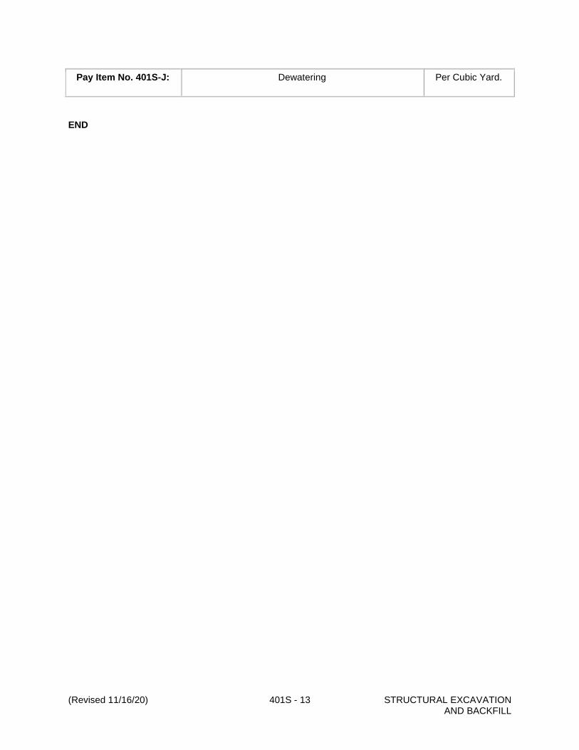
Pay Item No. 401S-J: Dewatering Per Cubic Yard.
END

(Revised 11/16/20) 402S - 1 CONTROLLED LOW STRENGTH MATERIAL
ITEM NO. 402S - CONTROLLED LOW STRENGTH MATERIAL
402S.1 - Description
This item governs Controlled Low Strength Material (CLSM) used for trench backfill and for filling
abandoned culverts, pipes, other enclosures, and for other uses as indicated on the drawings, Standard
Details or as approved by the Engineer or designated representative. CLSM is a low strength, self-
compacting, flowable, cementitious material used in lieu of soil backfill. It is intentionally prepared at low
strength to allow for future removal using conventional excavation equipment.
The CLSM shall be composed of Portland Cement (PC) or fly ash, or both, filler aggregate and water. The
CLSM, specified for use in filling abandoned culverts, pipes, or other enclosures, shall contain a
settlement compensator, in addition to the other ingredients, to minimize settlement of the CLSM within
the enclosure.
Normal Set CLSM shall be specified whenever the material will remain uncovered or will not be subjected
to traffic or other loads within 24 hours after placement. Fast Set CLSM shall be specified whenever the
material will be covered, subjected to traffic or other loads within 24 hours, or needed to expedite
construction.
CLSM can be used for permanent subgrade repairs below the base layer but shall not be used for
permanent pavement repairs. For temporary traffic applications, a minimum 2-inch cap composed of Hot
Mix-Cold Laid Asphaltic Concrete Pavement (TxDOT Standard Specification Item 334) shall be placed on
the CLSM.
402S.2 - Submittals
The submittal requirements of this specification item include:
1. A mix design submittal including the results of unconfined compressive strength tests, air
entrainment (if applicable), flow consistency, hardened unit weight, and timed Ball Drop and
corresponding Penetrometer tests.
2. Certifications and test results for the cement fly ash, and admixtures.
3. Particle-size gradation and specific gravity tests on the filler aggregate.
402S.3 - Materials
A. Cement.
PC shall conform to ASTM C 150, Type I (General Purpose).
PC manufactured in a cement kiln fueled by hazardous waste shall be considered as an approved
product if the production facility is authorized to operate under regulation of the Texas Commission
on Environmental Quality (TCEQ) and the U.S. Environmental Protection Agency (EPA). Supplier
shall provide current TCEQ and EPA authorizations to operate the facility.
B. Fly Ash
Fly ash shall conform to the requirements of Standard Specification Item No. 405, "Concrete
Admixtures" and TxDOT Specification Item 437.

(Revised 11/16/20) 402S - 2 CONTROLLED LOW STRENGTH MATERIAL
C. Filler Aggregate.
Filler aggregate shall consist of sand, stone screenings, pavement milling cuttings or other granular
material that is compatible with the other mixture components. The filler aggregate shall be fine
enough to stay in suspension to the extent required for proper flow without segregation, and, in the
case of filling of enclosures, for minimal settlement. Filler aggregate shall have a Plasticity Index
(TxDOT Test Method Tex-106-E) less than 15 and shall conform to the following gradation:
Sieve Designation US Percent Passing
No. 200 0—10
D. Mixing Water.
Mixing water shall conform to the requirements of Standard Specification Item No. 403, "Concrete for
Structures".
E. Settlement Compensator
An air entraining admixture with a higher than usual dosage, which meets the requirements of
Standard Specification Item No. 405, "Concrete Admixtures", shall be used as a settlement
compensator. The settlement compensator may be introduced to the CLSM at the job site by
placement of prepackaged admixture in capsules or bags in the mixing drum in accordance with the
admixture manufacturer's recommendations.
402S.4 - Mix Design
The proportioning of CLSM shall be the responsibility of the Contractor. The Contractor shall furnish a mix
design conforming to the requirements herein, for review and approval by the Engineer or designated
representative. The mix design shall be prepared by a qualified commercial laboratory and then reviewed
and signed by a registered Professional Engineer licensed in the State of Texas.
The Mix Design submittal must include:
A. Test results for unconfined compressive strength, air entrainment (if applicable), flow consistency,
hardened unit weight, and timed Ball Drop (ASTM C-360) and corresponding Penetrometer tests
(with a concrete pocket penetrometer),
B. Certifications and test results for the cement, fly ash, and admixtures, and
C. Results of particle-size gradation and specific gravity tests on the filler aggregate. The submittal shall
include Penetrometer tests performed every thirty minutes until the Ball Drop test shows a 2-inch
indentation, as well as the predicted Penetrometer reading that corresponds to a 3-inch Ball Drop
indentation. Particle-size gradation shall be determined using a series of sieves that gives no fewer
than five uniformly spaced points for graphing the entire range of particle sizes larger than a No. 200
sieve.

(Revised 11/16/20) 402S - 3 CONTROLLED LOW STRENGTH MATERIAL
The Contractor shall perform the work required to substantiate the design at no cost to the City, including
all testing. Approved mix designs shall be valid for one year, provided there are no changes in the type,
source, or characteristics of the materials during that year.
At the end of one year, the mix design may be submitted for renewal, provided that:
1. field tests of the CLSM during the year have been satisfactory,
2. there have been no changes in type or source of the materials of the mix, and
3. the characteristics of the materials have not changed significantly since the original submittal.
The Contractor shall also submit certifications and test results for the cement, fly ash and admixtures, and
particle-size gradation and specific gravity test results for the filler aggregate. The Contractor shall
compare results of tests made on the filler aggregate at the end of the year to the results of tests reported
in the original submittal. Gradation changes less than ten percent in percent passing any sieve and
specific gravity changes less than five percent shall not be considered significant.
402S.5 - Strength
The CLSM mix designs shall meet the unconfined compressive strength requirements outlined in the
table below. The compression tests shall be conducted in accordance with TxDOT Method Tex-418-A,
using approved unbonded caps on specimens with 4-inch diameter and 8-inch height [or 3-inch diameter
by 6-inch high specimens if a smaller capacity loading device gives more accurate results].
Unconfined Compressive Strength, psi
Age Normal Set CLSM Fast Set CLSM
3 hours — 35 minimum
24 hours 35 minimum —
28 days 300 maximum 300 maximum
402S.6 - Flow Consistency
Flow consistency shall be established in tests involving the use of a 6-inch length by 3-inch diameter
open-ended straight tubing made of steel, plastic or other non-absorbent material that is non-reactive with
cement or fly ash. The tube shall be placed with one end on a horizontal flat surface and held in a vertical
position. The tube shall then be filled to the top with CLSM. The top surface shall be struck off with a
suitable straight edge and any spillage shall be removed from the base of the tube. Within five seconds
thereafter the tube shall be raised carefully, using a steady upward lift with no lateral or torsional motion.
The entire test, from the start of filling until removal of the tube, shall be completed within 1½ minutes
without interruption.
After removal of the tube, the spread of the CLSM shall be measured immediately along two diameters
that are perpendicular to one another. The average of those two measurements is defined as the flow

(Revised 11/16/20) 402S - 4 CONTROLLED LOW STRENGTH MATERIAL
consistency of the mix. The flow consistency of the CLSM shall be considered satisfactory if a
circular-type spread of the mix occurs without segregation and a flow consistency (average diameter of
spread) of 8 inches or more is achieved.
402S.7 - Air Entrainment
Air entraining admixture shall be added as a settlement compensator, whenever the CLSM will be used to
fill an enclosure (Section 402S.1). The dosage shall be sufficient to result in an air content of 15 to 25
percent (as determined by TxDOT Method Tex-416-A) at the time of placement of the CLSM.
402S.8 - Field Strength Tests
Ball Drop or Penetrometer tests shall be used to determine, when the CLSM has developed sufficient
strength to be covered or subjected to traffic or other loads as approved by the Engineer or designated
representative.
The Ball Drop test shall be performed according to the latest version of ASTM C-360. An indentation
diameter of 3 inches or less, and the absence of a sheen or any visible surface water in the indentation
area shall indicate that the CLSM has achieved the desired strength. Because trench width and depth
may affect the test results, the Contractor may perform this test on a control sample of CLSM in a 2-foot
square by 6-inch deep container.
Penetrometer tests using a hand-held, spring reaction-type device commonly called a concrete pocket
penetrometer, shall be performed on the surface of the CLAMS. A Penetrometer reading, equal to or
greater than the value established in the mix design (Section 402S.4) for a Ball Drop test indentation of 3-
inches, shall indicate that the CLSM has achieved the desired strength.
402S.9 - Construction Methods
A. General
The height of free fall placement of the CLSM shall not exceed 4 feet. Since CLSM is considered to
be self-compacting, a vibrator shall not be allowed. The CLSM shall not be covered with any
overlying materials or subjected to traffic or other loads until the Ball Drop test or the Penetrometer
test shows acceptable results (Section 402S.8) or until the CLSM has been in place a minimum of
24 hours for Normal Set CLSM and a minimum of 3 hours for Fast Set CLSM. Curing of the CLSM
will not be required.
B. Utility Line Backfill
After the utility pipe has been placed and the proper bedding material placed in accordance with the
details on the drawings, the trench may be immediately backfilled with the CLSM to the subgrade
level shown on the drawings, Standard Details 1100S-6B & D, 430S-4 “Concrete Backfill Under Curb
and Gutter” or as directed by the Engineer or designated representative.
C. Culvert Backfill

(Revised 11/16/20) 402S - 5 CONTROLLED LOW STRENGTH MATERIAL
Care shall be taken to prevent movement of the structure. If the pipe or structure moves either
horizontally or vertically, the CLSM and the structure shall be immediately removed, and the pipe or
structure re-laid to proper line and grade.
D. Other Backfill
CLSM may be used for backfill material in lieu of soil as shown on the drawings, Standard Details or
as approved by the Engineer or designated representative.
E. Filling Abandoned Culverts, Pipe, or other Enclosures
The CLSM shall be placed in a manner that allows all air or water, or both, to be displaced readily as
the CLSM fills the enclosure.
402S.10 - Acceptance Testing During Construction
The Engineer or designated representative may perform flow consistency, air entrainment, and
unconfined compressive strength tests to determine if the CLSM meets the specification requirements.
The number and frequency of acceptance tests will be determined by the Engineer or designated
representative.
402S.11 - Measurement and Payment
The work and materials presented herein will generally not be paid for directly but shall be included in the
unit price bid for the item of construction in which this item is used.
When specified in the contract bid form as a separate pay item, the item will be paid for at the contract
unit bid price(s) for "Controlled Low Strength Material". The bid prices shall include full compensation for
all Work herein specified, including the furnishing of all materials, equipment, tools, labor and incidentals
necessary to complete the Work.
Payment will be made under the following:
Pay Item No. 402S-A: Controlled Low Strength Material Per Cubic Yard
END

(Revised 11/16/20) 403S - 1 CONCRETE FOR STRUCTURES
ITEM NO. 403S - CONCRETE FOR STRUCTURES
403S.1 - Description
This item shall govern quality, storage, handling, proportioning and mixing of materials for hydraulic
cement concrete construction of buildings, bridges, culverts, slabs, prestressed concrete and incidental
appurtenances.
403S.2 - Submittals
Within 14 days prior to the commencement of related work, the Contractor shall submit electronically the
following submittal requirements as applicable:
a. Technical literature including type of concrete and mix design option(s) of the class of concrete
required on the project,
b. The supplier of the concrete mix design(s) and type of mixing equipment,
c. Type of admixtures to be used with the concrete mixes,
d. Description of curing method used, and
e. Manufacturer of precast structures
403S.3 - Materials
Concrete shall be composed of Portland cement, water, aggregates (fine and coarse), and admixtures if
desired or required, proportioned and mixed as hereinafter to achieve specified results.
A. Cementitious Materials
Hydraulic cement shall conform to ASTM C 150, Type I (General Purpose), Type II (General
Purpose with Moderate Sulfate Resistance) and Type III (High Early Strength). Type I shall be used
when none is specified or indicated on the drawings. Type I and Type III cements shall not be used
when Type II cement is specified or indicated on the drawings. Type III cement may be used in lieu
of a Type I cement, when the anticipated air temperature for the succeeding 12 hours will not exceed
60°F (15.6°C). A Type III cement shall only be used in precast concrete or when otherwise specified
or allowed. All cement shall be of the same type and from the same source for a monolithic
placement.
Unless otherwise specified, the cementitious material content shall be limited to no more than 700
lbs. per cubic yard. When supplementary cementing materials are used, cement is defined as
"cement plus supplementary cementing material." Supplementary cementing materials include fly
ash (DMS-4610), ultra-fine fly ash (DMS-4610), ground granulated blast furnace slag grade 100 or
120 (DMS-4620), silica fume (DMS-4630) and metakaolin (DMS-4635).
Class C flyash shall not be used in sulfate-resistant concrete.
Hydraulic cement manufactured in a cement kiln fueled by hazardous waste shall be considered as
an approved equivalent product if the production facility is authorized to operate under regulation of
the Texas Commission on Environmental Quality (TCEQ) and the U.S. Environmental Protection
Agency (EPA). Supplier shall provide current TCEQ and EPA authorizations to operate the facility.

(Revised 11/16/20) 403S - 2 CONCRETE FOR STRUCTURES
When sulfate-resistant concrete is required for a project, mix design options 1, 2, 3 or 4 presented in
Section 403S.8, "Mix Design Options" shall be used to develop appropriate mix design utilizing Type
I/II, II, V, IP or IS cement.
B. Mixing Water
Water for use in concrete and for curing shall be potable water free of oils, acids, organic matter or
other deleterious substances and shall not contain more than 1,000 parts per million of chlorides as
Cl or sulfates as SO4.
Water from the City of Pflugerville will not require testing. Contractor may request approval of water
from other sources. Contractor shall arrange for samples to be taken from the source and tested at
the Contractor's expense. When water from other sources is proposed, test reports shall be provided
that indicates compliance with Table 1 before use.
Table 1: Chemical Limits for Mix Water
Contaminant Test Method Maximum Concentration (ppm)
Chloride (CL)
Prestressed concrete
Bridge decks & superstructure
All other concrete
ASTM D-512
500
500
1,000
Sulfate (SO 4 ) ASTM D-516 1,000
Alkalies (NA 2 O + 0.658 K 2 O) ASTM D-4191 & D-4192 600
Total Solids AASHTO T-26 50,000
Water that has an adverse effect on the air-entraining agent or any other chemical admixture or on
strength or time of set of the concrete shall not be used. Water used in white Portland Cement (PC)
concrete shall be free from iron and other impurities, which may cause staining, or discoloration.
C. Coarse Aggregate
Coarse aggregate shall consist of durable particles of crushed or uncrushed gravel, crushed blast
furnace slag, crushed stone or combinations thereof; free from frozen material or injurious amounts
of salt, alkali, vegetable matter or other objectionable material either free or as an adherent coating.
When white hydraulic cement is specified, the coarse aggregates used in the concrete shall be light
colored. Quality shall be reasonably uniform throughout.
The coarse aggregate from each source shall not contain more than 0.25 percent by weight of clay
lumps, nor more than 1.0 percent by weight of shale nor more than 5 percent by weight of laminated
and/or friable particles when tested in accordance with TxDOT Test Method Tex-413-A. The coarse
aggregate from each source shall have a wear of not more than 40 percent when tested in
accordance with TxDOT Test Method Tex-410-A.

(Revised 11/16/20) 403S - 3 CONCRETE FOR STRUCTURES
Unless otherwise indicated on the drawings, the coarse aggregate from each source shall be
subjected to 5 cycles of the soundness test conforming to TxDOT Test Method Tex-411-A. The loss
shall not be greater than 12 percent when sodium sulfate is used or 18 percent when magnesium
sulfate is used. A satisfactory record under similar conditions of service and exposure will be
considered in the evaluation of material failing to meet these requirements.
Coarse aggregate shall be washed. The Loss by Decantation (TxDOT Test Method Tex-406-A), plus
allowable weight of clay lumps, shall not exceed 1 percent or the value indicated on the drawings or
in the project manual, whichever is less. If material finer than the # 200 sieve is definitely established
to be dust of fracture of aggregates made primarily from crushing of stone, essentially free from clay
or shale as established by Part III of TxDOT Test Method Tex-406-A, the percent may be increased
to 1.5. When crushed limestone coarse aggregate is used in concrete pavements, the decant may
exceed 1% but not more than 3% if the material finer than the #200 sieve is determined to be at least
67% calcium carbonate in accordance with TxDOT Test Method Tex-406-A, Part III.
The coarse aggregate factor may not be more than 0.82; however, when voids in the coarse
aggregate exceed 48 percent of the total rodded volume, the coarse aggregate factor shall not
exceed 0.85. The coarse aggregate factor may not be less than 0.68 except for a Class I machine
extruded mix that shall not have a coarse aggregate factor lower than 0.61.
When exposed aggregate surfaces are required, the coarse aggregate shall consist of particles with
at least 40 percent crushed faces. Uncrushed gravel, polished aggregates and clear resilient
coatings are not acceptable for exposed aggregate finishes.
When tested by approved methods, the coarse aggregate including combinations of aggregates
when used, shall conform to the grading requirements shown in Table 2.
Table 2: Coarse Aggregate Gradation Chart (Percent Passing)
Grade Nom.
Size
2½″ 2″ 1½″ 1″ 3/4″ 1/2″ 3/8″ No. 4 No. 8
1 2” 100 80-100 50-85 20-40 0-5
2
(467)*
1½” 100 95-100 35-70 10-30 0-5
3 1” 100 95-100 60-90 25-60 0-5
4 (57)* 1” 100 95-100 25-60 0-10 0-5
5 (67)* 3/4” 100 90-100 20-55 0-10 0-5
6 (7)* 1/2” 100 90-100 40-70 0-15 0-5
7 3/8” 100 70-95 0-25
8 3/8” 100 95-100 20-65 0-10

(Revised 11/16/20) 403S - 4 CONCRETE FOR STRUCTURES
Notes:
1. Recycled crushed concrete fine aggregate shall be limited to a maximum of 20% of the
fine aggregate.
2. The use of recycled crushed hydraulic cement concrete as a coarse aggregate shall be
limited to Concrete Classes A, B and D (see Table 5).
D. Fine Aggregate
Fine aggregate shall be washed and consist of clean, hard, durable and uncoated particles of natural
or manufactured sand or a combination thereof, with or without a mineral filler. When white hydraulic
cement is specified, the fine aggregates used in the concrete shall be light colored. Quality shall be
reasonably uniform throughout. It shall be free from frozen material or injurious amounts of salt,
alkali, vegetable matter or other objectionable material and it shall not contain more than 0.5 percent
by weight of clay lumps in accordance with Tex-413-A. When subjected to color test for organic
impurities per TxDOT Test Method Tex-408-A, it shall not show a color darker than standard.
Unless indicated otherwise on the drawings the acid insoluble residue of fine aggregate used in slab
concrete subject to direct traffic shall not be less than 60 percent by weight (mass) when tested
conforming to TxDOT Test Method Tex-612-J.
Unless indicated otherwise on the Drawings, fine aggregate shall be blended, when necessary, to
meet the acid insoluble residue requirement.
When blending the following equation shall be used:
Acid Insoluble (%) = {(A1)(P1)+(A2)(P2)}/100
Where:
A1 = acid insoluble (%) of aggregate 1,
A2 = acid insoluble (%) of aggregate 2,
P1 = % by weight of A1 of the fine aggregate blend, and
P2 = % by weight of A2 of the fine aggregate blend.
When tested in accordance with TxDOT Test Method Tex-401-A, the fine aggregate, including
mineral filler and combinations of aggregates, when used, shall conform to the grading requirements
shown in Table 3.
Table 3: Fine Aggregate Gradation Chart 1 (Grade 1 - Percent Passing)
3/8 No. 4 No. 8 No. 16 No. 30 No. 50 No. 100 No. 200
100 95-100 80-100 50-85 25-65 10-35 0-10 0-32

(Revised 11/16/20) 403S - 5 CONCRETE FOR STRUCTURES
Notes:
1. Recycled crushed concrete fine aggregate shall be limited to a maximum of 20% of the
fine aggregate.
2. The use of recycled crushed hydraulic cement concrete as a fine aggregate shall be
limited to Concrete Classes A, B and D (see Table 5).
3. 6 to 35 when sand equivalent value is greater than 85.
4. 0 to 6 for manufactured sand.
Fine aggregate will be subjected to Sand Equivalent Test per TxDOT Test Method Tex-203-F. Sand
Equivalent shall not be less than 80 nor less than otherwise indicated on the drawings, whichever is
greater.
The fineness modulus will be determined by adding the percentages by weight retained on sieve
Nos. 4, 8, 16, 30, 50 and 100 and dividing the sum of the six sieves by 100. For all classes of
concrete except K (see Table 5), the fineness modulus shall be between 2.30 and 3.10. For Class K
concrete, the fineness modulus shall be between 2.6 and 2.8, unless indicated otherwise on the
Drawings.
E. Mineral Filler
Mineral filler shall consist of stone dust, clean crushed sand or other approved inert material. When
tested in accordance with TxDOT Test Method Tex-401-A, it shall conform to the following gradation:
Passing the No. 30 Sieve 100 percent
Passing the No. 200 Sieve 65 to 100 percent
F. Mortar and Grout
Unless otherwise specified, indicated on the drawings or approved by the City Engineer or
designated representative mortar and grout shall consist of 1 part cement, 2 parts finely graded sand
and enough water to make the mixture plastic. When required to prevent color difference, white
cement shall be added to produce color required. When required by the City Engineer or designated
representative, approved latex adhesive may be added to the mortar. Mortar shall be provided with a
consistency such that the mortar can be easily handled and spread by trowel. Grout shall be
provided of a consistency that will flow into and completely fill all voids.
G. Admixtures
All chemical admixtures including water reducing, placticizers and air entrainment shall conform to
TxDOT DMS-4640, "Chemical Admixtures for Concrete". Calcium chloride-based admixtures shall
not be approved. Unless otherwise noted, air-entraining, retarding and water reducing admixtures
may be used in all concrete. Admixtures shall be included in the prequalified concrete admixtures list
maintained by TxDOT's Construction Division (latest edition). High-range water-reducing admixtures

(Revised 11/16/20) 403S - 6 CONCRETE FOR STRUCTURES
(TxDOT Type F or G) and accelerating admixtures (TxDOT Type C or E) shall not be used in bridge
deck concrete.
H. Air Entrainment
Unless indicated otherwise on the drawings, all concrete classes with the exception of Class B shall
be air entrained in accordance with Table 8. If the air content is more than 1½ percentage points
below or 3 percentage points above the required air, the load of concrete will be rejected. If the air
content is more than 1½ but less than 3 percentage points above the required air, the concrete may
be accepted based on strength test results.
403S.4 - Storage of Materials
A. Cement, Supplementary Cementing Materials and Mineral Filler
All cement, supplementary cementing materials and mineral filler shall be stored in separate and well
ventilated, weatherproof buildings or approved bins, which will protect the material from dampness or
absorption of moisture. Storage facilities shall be easily accessible, and each shipment of packaged
cement shall be kept separated to provide for identification and inspection. The City Engineer or
designated representative may permit small quantities of sacked cement to be stored in the open for
a maximum of 48 hours on a raised platform and under waterproof covering.
B. Aggregates
The method of handling and storing concrete aggregates shall prevent contamination with foreign
materials. If the aggregates are stored on the ground, the sites for the stockpiles shall be clear of all
vegetation and shall be level. Aggregates shall be stockpiled in sizes to facilitate blending. If the
aggregate is not stockpiled on a hard, non-contaminant base, the bottom 6-inch layer of the stockpile
shall not be used without recleaning the aggregate.
When conditions require the use of 2 or more grades of coarse aggregates, separate stockpiles shall
be maintained to prevent intermixing. Where space is limited, stockpiles shall be separated by walls
or other appropriate barriers.
Aggregate shall be stockpiled and protected from the weather a minimum of 24 hours prior to use to
minimize free moisture content. When stockpiles are too large to protect from the weather, accurate
and continuous means acceptable to the City Engineer or designated representative shall be
provided to monitor aggregate temperature and moisture. Aggregates shall be stockpiled and
handled such that segregation and contamination are minimized.
The stockpiles shall be sprinkled to control moisture and temperature as necessary. A reasonably
uniform moisture content shall be maintained in aggregate stockpiles.
C. Admixtures
Admixtures shall be stored in accordance with manufacturer's recommendations and shall be
protected against freezing.
D. Hot Weather Concrete Mixes
Ice may be used during hot weather concrete placement (Section 13 of Standard Specification Item
No. 410S, "Concrete Structures") to lower the concrete temperature; however, the Contractor shall

(Revised 11/16/20) 403S - 7 CONCRETE FOR STRUCTURES
furnish a mix design acceptable to the City Engineer or designated representative for class of
concrete specified. The addition of ice shall not exceed 50% of the total mix water weight.
403S.5 - Measurement of Materials
Water shall be accurately metered. Fine and coarse aggregates, mineral filler, bulk cement and fly ash
shall be weighed separately. Allowances shall be made in the water volume and aggregate weights
during batching for moisture content of aggregates and admixtures. Volumetric and weight measuring
devices shall be acceptable to the City Engineer or designated representative. Measurement of materials
in non-volumetric and volumetric mixers shall conform TxDOT Specification Item 421, "Hydraulic Cement
Concrete".
Batch weighing of sacked cement is not required; however, bags, individually and entire shipments, may
not vary by more than 3 percent from the specified weight of 94 pounds per bag. The average bag weight
of a shipment shall be determined by weighing 50 bags taken at random.
403S.6 - Mix Design
The Contractor shall furnish a mix design acceptable to the City Engineer or designated representative for
the class of concrete required in accordance with Table 5. The mix shall be designed by a qualified
commercial laboratory and/or concrete technician and signed/sealed by a registered Professional
Engineer, licensed in the state of Texas to conform with requirements contained herein, to ACI 211.1 or
TxDOT Bulletin C-11 (and supplements thereto). The maximum water-to-cementitious material ratio
identified in Table 5 for specific classes of concrete shall not be exceeded.
A higher-strength class of concrete with equal or lower water-to-cementitious-material ratio may be
substituted for the specified class of concrete.
The mix design shall be over-designed in accordance with Table 5 in order to account for production
variability and to ensure minimum compressive strength requirements are met.
Allowable mix design options are presented in Section 403S.8.
The Contractor shall perform, at the Contractor's expense, the work required to substantiate the design,
including testing of strength specimens. Complete concrete design data shall be submitted to the City
Engineer or designated representative for approval. The mix design will be valid for a period of one (1)
year provided that there are no changes to the component materials. In lieu of the above mix design, the
Contractor may accept a design furnished by the City. However, this will not relieve him of providing
concrete meeting the requirements of these specifications.
It shall also be the responsibility of the contractor to determine and measure the batch quantity of each
ingredient, including all water, so that the mix conforms to these specifications and any other
requirements shown on the Drawings.
When there are changes in aggregates or in type, brand or source of cement, supplementary cementing
material or chemical admixtures, the mix shall be evaluated as a new mix design. A change in vendor
does not necessarily constitute a change in materials or source. When only the brand or source of
cement is changed and there is a prior record of satisfactory performance of the cement with the
ingredients, the submittal of new trial batches may be waived by the City Engineer or designated
representative.

(Revised 11/16/20) 403S - 8 CONCRETE FOR STRUCTURES
At the end of one (1) year, a previously approved mix may be resubmitted for approval if it can be shown
that no substantial change in the component materials has occurred and that test results confirming the
adequacy of the mix designs have been acquired during the previous year. The resubmittal analysis must
be reviewed, signed and sealed by a registered Professional Engineer, licensed in the state of Texas.
This resubmittal shall include a reanalysis of specific gravity, absorption, fineness modulus, sand
equivalent, soundness, wear and unit weights of the aggregates. Provided that the fineness modulus did
not deviate by more than 0.20 or that the re-proportioned total mixing water, aggregate and cement (or
cement plus fly ash) are within 1, 2, and 3 percent, respectively, of pre-approved quantities, a one-year
extension on the approval of the mix may be granted by the City Engineer or designated representative.
Updated cement, fly ash, and admixture certifications shall accompany the resubmittal.
Approved admixtures that are included in the prequalified concrete admixtures list maintained by TxDOT's
Construction Division may be used with all classes of concrete at the option of the Contractor provided
that specific requirements of the governing concrete structure specification are met. Water reducing and
retarding agents shall be required for hot weather, large mass, and continuous slab placements. Air
entraining agents may be used in all mixes but must be used in the classes indicated on Table 5. Unless
approved by the City Engineer or designated representative, mix designs shall not exceed air contents for
extreme exposure conditions as recommended by ACI 211.1 for the various aggregate grades.
403S.7 - Consistency and Quality of Concrete
Concrete shall be uniform, workable, cohesive, possess satisfactory finishing qualities and of stiffest
consistency that can be placed and vibrated into a homogeneous mass within slump requirements
specified in Table 4 without the development of segregation or honeycombing. No concrete will be
permitted with a slump in excess of the maximums shown unless water-reducing admixtures have been
previously approved. Concrete that exceeds the maximum acceptable placement slump at time of
delivery will be rejected. Slump values shall be conducted in accordance with TxDOT Test Method Tex-
415-A.
Consistency and quality of concrete should allow efficient placement and completion of finishing
operations before initial set. Re-tempering (i.e. addition of water and reworking concrete after initial set)
shall not be allowed. When field conditions are such that additional moisture is needed for final concrete
surface finishing operation, the required water shall be applied to surface by fog spray only and shall be
held to a minimum. Excessive bleeding shall be avoided and in no case will it be permissible to expedite
finishing and drying by sprinkling the surface with cement powder.
Table 4: Slump Requirements
Slump 1 , inches
Type of Construction Maximum Minimum
Cased Drilled Shafts 4 3
Reinforced Foundation Caissons and Footings 3 1
Reinforced Footings and Substructure Walls 3 1
Uncased Drilled Shafts 6 5
Thin-walled Sections; 9 inches or less 6½ 4
Prestressed Concrete Members 6½ 4
Precast Drainage Structures 6 4

(Revised 11/16/20) 403S - 9 CONCRETE FOR STRUCTURES
Wall Sections over 9 inches 5 3
Reinforced Building Slabs, Beams, Columns and Walls 4 1
Bridge Decks 4 2
Pavements, Fixed-form 6½ 4
Table 4 (continued): Slump Requirements
Slump 1 , inches
Type of Construction Maximum Minimum
Pavements, Slip-form 3 1½
Sidewalks, Driveways and Slabs on Ground 4 2
Curb & Gutter, Hand-vibrated 3 1
Curb & Gutter, Hand-tamped or spaded 4 2
Curb & Gutter, Slip-form/extrusion machine 2 1/2
Heavy Mass Construction 2 1
High Strength Concrete 4 3
Riprap and Other Miscellaneous Concrete 6 1
Under Water or Seal Concrete 8½ 6
Notes:
1. Slump values when a high range water reducer (HRWR) is not used.
2. When a high range water reducer (HRWR) is used, maximum acceptable placement slump
will be 9 in.
During progress of the work, the City Engineer or designated representative shall cast test cylinders as a
check on compressive strength of concrete actually placed. The City Engineer or designated
representative may also perform slump tests, entrained air tests and temperature checks to ensure
compliance with specifications.
Proportioning of all material components shall be checked prior to discharging. Excluding mortar material
for pre-coating of the mixer drum [see section 403S.8.B] and adjustment for moisture content of
admixtures and aggregates, material components shall fall within the range of + 1% for water, + 2% for
aggregates, + 3% for cement, + 2% for fly ash and within manufacturer recommended dosage rates for
admixtures except that air entrainment shall be within + 1½ percentage points of the mix design
requirements.
Unless otherwise specified or indicated on the drawings, concrete mix temperature shall not exceed 90°F
except in mixes with high range water reducers where a maximum mix temperature of 100°F will be
allowed. Cooling an otherwise acceptable mix by addition of water or ice during agitation will not be
allowed.
Test cylinders will be required for small placements such as manholes, inlets, culverts, wing walls, etc.
The City Engineer or designated representative may vary the number of tests to a minimum of 1 for each
25 cubic yards placed over a several-day period.

(Revised 11/16/20) 403S - 10 CONCRETE FOR STRUCTURES
Test cylinders shall be required for each monolithic placement of bridge decks or superstructures, top
slabs of direct traffic culverts, cased drilled shafts, structural beams and as otherwise directed by the City
Engineer or designated representative for design strength confirmation or early form removal. Test
cylinders made for early form removal or for consideration of use of structure will be at Contractor's
expense, except when required by the City Engineer or designated representative.
A strength test shall be defined as the average breaking strength of 2 cylinders. A minimum of four test
cylinders shall be prepared; two each to be tested at 7 and 28 days. Specimens will be tested conforming
to TxDOT Test Method Tex-418-A. If required strength or consistency of class of concrete being produced
cannot be secured with minimum cementitious material specified or without exceeding maximum
water/cementitious material ratio, Contractor will be required to furnish different aggregates, use a water
reducing agent, an air entraining agent or increase the cement content in order to provide concrete
meeting these specifications.
Slump tests will be performed in accordance with TxDOT Test Method Tex-415-A. Entrained air tests will
be performed in accordance with TxDOT Test Method Tex-416-A.
Test specimens shall be cured using the same methods and under the same conditions as the concrete
represented. Design strength cylinders shall be cured conforming to TxDOT Bulletin C-11 (and
supplements thereto).
When control of concrete quality is by 28-day compressive tests, job control testing will be by 7-day
compressive strength tests. The minimum strength requirement for seven (7) day test will be 70 percent
of the specified minimum 28-day compressive strength. If the required 7-day strength is not secured with
the quantity of cement specified in Table 4, changes in the mix design shall be made and resubmitted for
approval. For an occasional failure of the seven-day compressive test, the concrete may be tested at 28
days for final evaluation.
Concrete
Classification
Sacks of
Cement
per CY
Min.
Compressive
Strength (28f' c)
28 Day (psi)
Min. Beam
Strength
7 Day
Max.
Water/Cement
Ratio
(gal/sack)
Coarse
Aggregate No.5
A7 5.0 3000
425
3903 6.5 1-2-3-4-81,4
B 4.5 2500 300 8 2-3-4-5-6-7
C6,7 6.0 3600 510 6 1-2-3-4-5
D 3.0 1500 215 11 2-3-4-5-6-7
E 6.0 3000 425 6 2-3-4-5
S7 6.5 4000 570
5253 5 2-3-4-5
P 5.0 N/A 5552 6.25 2-3
DC 8.75 5500 720 3.6 6

(Revised 11/16/20) 403S - 11 CONCRETE FOR STRUCTURES
CO 7.0 4600 640 4.5 6
SS 7.0 3600 510 5.5 3-4-5
Notes:
1. Grade 8 aggregate for use in extended coarse and extruded curbs, unless a larger size is
approved by the City Engineer or designated representative.
2. Minimum running average of concrete pavement.
3. When Type II or Type I / II cement is used.
4. Unless otherwise permitted by the City Engineer, Grade I coarse aggregate may only be
used in massive foundations with 4-inch minimum clear spacing between reinforcing steel
bars
5. Grade 1 coarse aggregate grading shall not be used in drilled shafts.
6. Structural concrete classes.
7. When Type II cement is used in Class C, S or A concrete, the 7-day compressive strength
requirement will be 2310 psi for Class C, 2570 psi for Class S and 1925 psi for Class A
minimum.
Table 6: Over Design Required to Meet Compressive Strength Requirements 1
Number Of Tests 2,3
Standard Deviation, psi
300 400 500 600 700
15 470 620 850 1,120 1,390
20 430 580 760 1,010 1,260
30 or more 400 530 670 900 1,130
Notes:
1. When designing the mix, add the tabulated amounts to the minimum design strength in Table
5. Maximum water-cement or water-cementitious ratio by weight
2. Number of tests of a concrete mixture used to estimate the standard deviation of a concrete
production facility. Test of another mix within 1,000 psi of the specified strength may be used.
3. If less than 15 prior tests are available, the overdesign should be 1,000 psi for specified
strength less than 3,000 psi, 1,200 psi for specified strengths from 3,000 to 5,000 psi and
1,400 psi for specified strengths greater than 5,000 psi.

(Revised 11/16/20) 403S - 12 CONCRETE FOR STRUCTURES
Table 7: Expected Usage of Concrete Classes
Class General Usage
A Drilled shafts, culverts (except top of slab of direct traffic culvers), inlets, manholes, headwalls,
approach slabs, curb, gutter, curb & gutter, concrete retards, sidewalks, driveways, backup walls
and anchors
B Riprap, small roadside signs and anchors
C 5 Drilled shafts, bridge substructure, bridge railing, culverts (except top slab of direct traffic culverts),
headwalls, wing walls, approach slabs, and cast-in-place concrete traffic barrier
Table 7 (Continued): Expected Usage of Concrete Classes
Class General Usage
D Riprap
E Seal concrete
S Bridge slab, top slab of direct traffic culvert, bridge sub-structure
P Concrete pavement
DC Dense concrete overlay
CO Concrete overlay
SS Slurry displacement shafts, underwater drill shafts
Table 8: Air Entrainment 1
Nominal Maximum Aggregate Size, In. % Air Entrainment2
Moderate Exposure Severe Exposure
3/8 - Grades 7 & 8 6 7½
1/2 - Grades 6 5½ 7
3/4 - Grades 5 5 6
1 - Grades 4 4½ 6
1½ - Grades 2 & 3 4½ 5½
2 - Grades 2 4 5
Notes:

(Revised 11/16/20) 403S - 13 CONCRETE FOR STRUCTURES
1. For specified concrete strengths above 5,000 psi a reduction of 1 percentage point is
allowed.
2. Grade 8 aggregate for use in extended course and extruded curbs, unless a larger size is
approved by the City Engineer or designated representative.
403S.8 - Mix Design Options
For the structural concretes identified in Table 5 (Class C) and any other class of concrete designed using
more than 520 lbs. of cementitious material per cubic yard, one of the mix design options presented
below shall be used.
For the non-structural concretes identified in Table 5 (Classes A, B, D, E, S, P, DC, CO and SS) and any
other class of concrete designed using less than 520 lbs. of cementitious material per cubic yard, one of
the mix design options presented below will be used, except that Class C fly ash may be used instead of
Class F fly ash for Options 1, 3 and 4 unless a sulfate-resistant concrete is required.
A. Option 1: Twenty (20) to thirty-five (35) percent of the cement may be replaced with Class F fly ash.
B. Option 2: Thirty-five (35) to fifty (50) percent of the cement may be replaced with ground granulated
blast-furnace slag.
C. Option 3: Thirty-five (35) to fifty (50) percent of the cement may be replaced with a combination of
Class F fly ash, ground granulated blast-furnace slag or silica fume. The combination may not include
more than thirty-five (35) percent fly ash and no more than ten (10) percent silica fume.
D. Option 4: Type IP or Type IS will be used and up to ten (10) percent of the cement may be replaced
with Class F fly ash, ground granulated blast-furnace slag or silica fume.
E. Option 5: Thirty-five (35) to fifty (50) percent of the cement may be replaced with a combination of
Class C fly ash and at least six (6) percent of silica fume, ultra-fine fly ash or metakaolin. The
combination may not include more than thirty-five (35) percent fly ash and no more than ten (10)
percent silica fume.
F. Option 6: A lithium nitrate admixture will be added at a minimum dosage of 0.55 gal. of thirty (30)
percent lithium nitrate solution per pound of alkalis present in the hydraulic cement.
G. Option 7: When hydraulic cement only is used in the design, the total alkali contribution from the
cement in the concrete does not exceed 4.0 lbs. per cubic yard, when calculated as follows:
alkali (lbs. per CY) = .01 (lbs cement/CY) (% Na2O equivalent in cement)
where (% Na2O equivalent in cement) is assumed to be the maximum cement alkali content
reported on the cement mill certificate.
H. Option 8: When there are deviations from Options 1 through 7, the following shall be performed:
1. Conduct tests on both coarse and fine aggregate separately in accordance with
ASTM C-1260, using 440 g of the proposed cementitious in the same proportions of
hydraulic cement to supplementary cementing material to be used in the mix.

(Revised 11/16/20) 403S - 14 CONCRETE FOR STRUCTURES
2. Prior to use of the mix, a certified test report signed and sealed by a Professional Engineer,
licensed in the state of Texas shall be submitted that demonstrates that ASTM C 1260 test
results for each aggregate do not exceed 0.10 percent expansion.
403S.9 - Mixing and Mixing Equipment
All equipment, tools and machinery used for hauling materials and performing any part of the work shall
be maintained in such condition to insure completion of the work without excessive delays for repairs and
replacement. Mixing shall be done in a mixer of approved type and size that will produce uniform
distribution of material throughout the mass and shall be capable of producing concrete meeting
requirements of ASTM C 94, Ready-mixed concrete and these specifications. Mixing equipment shall be
capable of producing sufficient concrete to provide required quantities. Entire contents of the drum shall
be discharged before any materials are placed therein for a succeeding batch. Improperly mixed concrete
shall not be placed in a structure. For all mixers an adequate water supply and an accurate method of
measuring the water shall be provided.
The concrete shall be mixed in quantities required for immediate use. Re-tempering of concrete will not
be permitted unless concrete is delivered in a truck-mixer.
In threatening weather, which may result in conditions that will adversely affect quality of the concrete to
be placed, the City Engineer or designated representative may order postponement of the work. Where
work has been started and changes in weather conditions require protective measures, the Contractor
shall furnish adequate shelter to protect the concrete against damage from rainfall, or freezing
temperatures. If necessary to continue operations during rainfall, the Contractor shall also provide
protective coverings for the material stock piles. Aggregate stockpiles need to be covered only to the
extent necessary to control the moisture conditions in the aggregates to adequately control the
consistency of the concrete.
The mixer may be batched by either volumetric or weight sensing equipment and shall be equipped with a
suitable timing device that will lock the discharging mechanism and signal when specified time of mixing
has elapsed.
A. Proportioning and Mixing Equipment
For all miscellaneous concrete placements, a mobile, continuous, volumetric mixer or a volumetric or
weight batch mixer of the rotating paddle type may be used.
When approved by the City Engineer or designated representative in writing or when specified for
use in other items, these mixers may be used for other types of concrete construction, including
structural concrete, if the number of mixers furnished will supply the amount of concrete required for
the particular operation in question.
These mixers shall be designed to receive all the concrete ingredients, including admixtures,
required by the mix design in a continuous uniform rate and mix them to the required consistency
before discharging.
For continuous volumetric mixers, the materials delivered during a revolution of the driving
mechanism or in a selected interval, will be considered a batch and the proportion of each ingredient
will be calculated in the same manner as for a batch type plant.

(Revised 11/16/20) 403S - 15 CONCRETE FOR STRUCTURES
Mixing time shall conform to recommendations of manufacturer of mixer unless otherwise directed by
the City Engineer or designated representative.
B. Ready-mixed Concrete
Use of ready-mixed concrete will be permitted provided the batching plant and mixer trucks meet
quality requirements specified herein. When ready-mixed concrete is used, additional mortar (1 sack
cement, 3 parts sand and sufficient water) shall be added to each batch to coat the mixer drum.
Ready-mixed concrete, batching plant and mixer truck operation shall include the following:
1. A ticket system will be used that includes a copy for the Inspector. Ticket will have machine
stamped time/date of concrete batch, a mix design designation, weight of cement, fly ash,
sand and aggregates; exact nomenclature and written quantities of admixtures and water.
Any item missing or incomplete on ticket may be cause for rejection of concrete.
2. Sufficient trucks will be available to support continuous placements. The Contractor will
satisfy the City Engineer or designated representative that adequate standby trucks are
available to support monolithic concrete placement requirements.
3. A portion of mixing water required by the mix design to produce the specified slump may be
withheld and added at the job site, but only with permission of the City Engineer or
designated representative and under the Inspector's observation. When water is added
under these conditions, the concrete batch will be thoroughly mixed before any slump or
strength samples are taken. Additional cement shall not be added at the job site to otherwise
unacceptable mixes.
4. A metal plate(s) shall be attached in a prominent place on each truck mixer plainly showing
the various uses for which it was designed. The data shall include the drum's speed of
rotation for mixing and for agitating and the capacity for complete mixing and/or agitating
only. A copy of the manufacturer's design, showing dimensions of blades, shall be available
for inspection at the plant at all times. Accumulations of hardened concrete shall be removed
to the satisfaction of the City Engineer or designated representative.
5. The loading of the transit mixers shall not exceed capacity as shown on the manufacturer's
plate attached to the mixer or 63 percent of the drum volume, whichever is the lesser
volume. The loading of transit mixers to the extent of causing spill-out en route to delivery
will not be acceptable. Consistent spillage will be cause for disqualification of a supplier.
6. Excess concrete remaining in the drum after delivery and wash water after delivery shall not
be dumped on the project site unless approval of the dump location is first secured from the
City Engineer or designated representative.
C. Volumetric Batching
Use of volumetric batched concrete will be permitted provided the batching and continuous mixing
operations conform to ASTM C 685, "Concrete Made By Volumetric Batching and Continuous
Mixing." This type concrete shall be made from materials continuously batched by volume, mixed in
a continuous mixer and delivered to the site in a freshly mixed and unhardened state. Tests and
criteria for batching accuracy and mixing efficiency shall be as specified in ASTM C 685.

(Revised 11/16/20) 403S - 16 CONCRETE FOR STRUCTURES
1. A ticket system will be used that includes a copy for the Inspector. The ticket will have machine
stamped time/date of concrete batch, a mix design designation, weight of cement, fly ash, sand
and aggregates; exact nomenclature and written quantities of admixtures and water. Any item
missing or incomplete on ticket may be cause for rejection of concrete.
2. Each batching or mixing unit, or both, shall carry in a prominent place a metal plate or plates on
which are plainly marked the gross volume of the unit in terms of mixed concrete, discharge
speed and the weight-calibrated constant of the machine in terms of a revolution counter or
other output indicator. The mixer shall produce a thoroughly mixed and uniform concrete.
3. The batcher-mixer unit shall contain in separate compartments all the necessary ingredients
needed for the manufacture of concrete. The unit shall be equipped with calibrated
proportioning devices to vary the mix proportions and it shall produce concrete as required by
the Work and ASTM C 685.
D. Truck-mixed Concrete
The concrete shall be mixed in a truck mixer from 70 to 100 revolutions at the mixing speed
designated by the manufacturer that will produce a uniform concrete mix. The concrete shall be
delivered to the project in a thoroughly mixed and uniform mass and shall be discharged with a
satisfactory degree of uniformity. Additional mixing at the job site, at the mixing speed designated by
the manufacturer, may be allowed by the City Engineer or designated representative as long as the
concrete is discharged before the drum has revolved a total of 300 revolutions after the introduction
of the mixing water to the cement and the aggregates.
Re-tempering or adding concrete chemical admixtures is only permitted at the job site when concrete
is delivered in a truck mixer. Water shall not be added after introduction of mixing water at the batch
plant except on arrival at the job site with approval of the City Engineer or designated representative,
in order to adjust the slump of the concrete. When this water is added, the mix design
water-cementitious-material ratio shall not be exceeded. The drum or blades shall be turned at least
30 additional revolutions at mixing speed to ensure thorough and uniform mixing of the concrete.
Water or chemical admixtures shall not be added to the batch after any concrete has been
discharged.
When the concrete contains silica fume, mixing times and batching operations shall be adjusted as
necessary to ensure that the material is completely and uniformly dispersed in the mix. The
dispersion of the silica fume within the mix shall be verified in trial batches.
E. Hand-mixed Concrete
Hand mixing of concrete may be permitted for small placements or in case of an emergency and
then only on authorization of the City Engineer or designated representative. Hand-mixed batches
shall not exceed a 4 cubic foot batch in volume. Material volume ratios shall not be leaner than 1 part
cement, 2 parts large aggregate, 1 part fine aggregate and enough water to produce a consistent
mix with a slump not to exceed 4 inches. Admixtures shall not be used unless specifically approved
by the City Engineer or designated representative.

(Revised 11/16/20) 403S - 17 CONCRETE FOR STRUCTURES
403S.10 - Excavation, Placing of Concrete, Finishing, Curing and Backfill
Excavation, placing of concrete, finishing, curing and backfill shall conform to Standard Specification Item
No. 401S, "Structural Excavation and Backfill", Standard Specification Item No. 410S, "Concrete
Structures" and Standard Specification Item No. 411S, "Surface Finishes for Concrete".
A. Placing Concrete in Cold Weather
Concrete may be placed when the atmospheric temperature is not less than 35°F. Concrete shall
not be placed in contact with any material coated with frost or having a temperature less than
32°F.
403S.11 - Measurement
Where measurement of concrete for a structure is not provided by another governing pay item,
measurement shall be made under this specification in accordance with the following.
The quantities of concrete of the various classifications which constitute the completed and accepted
structure or structures in place will be measured by the cubic yard, each, square yard, or linear foot as
indicated in the Contract Documents. Measurement will be as follows:
A. General
1. Measurement based on dimensions shall be for the completed structure as measured in place.
However, field-measured dimensions shall not exceed those indicated on the drawings or as
may have been directed by the City Engineer or designated representative in writing.
2. No deductions shall be made for chamfers less than 2 inches in depth, embedded portions of
structural steel, reinforcing steel, nuts, bolts, conduits less than 5 inches in diameter, pre/post
tensioning tendons, keys, water stops, weep holes and expansion joints 2 inches or less in
width.
3. No measurement shall be made for concrete keys between adjoining beams or prestressed
concrete planks.
4. No measurement shall be made for fill concrete between the ends or adjoining prestressed
concrete planks/box beams at bent caps or between the ends of prestressed concrete
planks/box beams and abutment end walls.
5. No measurement shall be made for inlet and junction box invert concrete.
6. No measurement shall be made for any additional concrete required above the normal slab
thickness for camber or crown.
B. Plan Quantity. For those items measured for plan quantity payment, adequate calculations have
been made. If no adjustment is required by Article 403S.11, additional measurements or calculations
will not be required or made.
C. Measured in Place. For those items not measured for Plan Quantity payment, measurement will be
made in place, subject to the requirements of Article 403S.10.A.1 above.

(Revised 11/16/20) 403S - 18 CONCRETE FOR STRUCTURES
403S.12 - Payment
The work performed and materials furnished as prescribed by this item and measured in accordance with
the applicable provisions of "Measurement" above will be paid for as follows.
The quantity to be paid for will be that quantity indicated in the contract documents and/or shown on the
drawings, regardless of errors in calculations, except as may be modified by the following.
Plan Quantities will be adjusted:
A. When a complete structure element has been erroneously included or omitted from the drawings,
the quantity shown on the drawings for that element will be added to or deducted from the plan
quantity and included for payment. A complete structure element will be the smallest portion of a
total structure for which a quantity is included on the drawings. Quantities revised in this manner will
not be subject to the provisions of the "General Conditions", Article 11.
B. When the plan quantity for a complete structure element is in error by 5 percent or more, a
recalculation will be made, and the corrected quantity included for payment. Quantities revised in
this manner will not be subject to the provisions of the "General Conditions", Article 11.
C. When quantities are revised by a change in design, the "plan quantity" will be increased or
decreased by the amount involved in the design change. Quantities revised in this manner will be
subject to the provisions of the "General Conditions", Article 11.
The party to the contract requesting the adjustment shall present to the other, a copy of the
description and location, together with calculations of the quantity for the structure element involved.
When this quantity is certified correct by the City Engineer or designated representative, it will
become the revised plan quantity.
Payment for increased or decreased costs due to a change in design on those items measured as
"Cubic Yard", "Each", "Square Foot", "Square Yard" or "Linear Foot" will be determined by Change
Order. Quantities revised in this manner will be subject to the provisions of the "General Conditions",
Article 11.
The unit prices bid for the various classes of concrete shown shall include full compensation for
furnishing, hauling, and mixing all concrete material; placing, finishing and curing all concrete; all
grouting, pointing and finishing; furnishing and placing drains; furnishing and placing metal flashing
strips; furnishing and placing expansion joint material required by this item; and for all forms and
false work, labor, tools, equipment and incidentals necessary to complete the work.
Pay Item No. 403S-CY: (Structure or Structural Component) Per Cubic Yard.
Pay Item No. 403S-EA: (Structure or Structural Component) Per Each.
Pay Item No. 403S-SY: (Structure or Structural Component) Per Square Yard.
Pay Item No. 403S-LF: (Structure or Structural Component) Per Lineal Foot.
END

(Revised 11/16/20) 404S - 1 PNEUMATICALLY PLACED CONCRETE
ITEM NO. 404S - PNEUMATICALLY PLACED CONCRETE
404S.1 - Description
This item shall govern furnishing and placing of "Pneumatically Placed Concrete" for riprap, concrete
channel, canal lining, tunnel lining, encasement of designated structural steel members, covering of
designated portions of concrete structures, repair of deteriorated or damaged concrete and other
miscellaneous construction as indicated on the drawings.
404S.2 - Submittals
The submittal requirements of this specification item may include:
A. Mix design of the class (Type I or Type II) of concrete required on the project (encasement, repair,
rip-rap, ditch lining),
B. Application process (wet or dry),
C. Work experience of the superintendent and workers performing specialized tasks to be employed on
the project, and
D. Type of Expansion joint material to be used on the project.
404S.3 - Materials
Unless indicated otherwise on the drawings, Class II Portland cement concrete shall be used for
encasement and Class I Portland cement concrete shall be used for repair.
Cement, water and sand shall conform to the requirements of Standard Specification Item No. 403S,
"Concrete for Structures." Specifically, the fine aggregate shall conform to the requirements of Table 2and
the coarse aggregate shall conform to the requirements of Table 1, Grade 7, unless otherwise indicated
on the drawings.
Air entraining admixtures, retarders and water reducing admixtures, if used, shall comply with Standard
Specification Item No. 405S, "Concrete Admixtures."
Bar reinforcement and wire fabric reinforcement shall conform to Standard Specification Item No. 406S,
"Reinforcing Steel."
Expansion joint material shall conform to the requirements of Standard Specification Item No. 410S,
"Concrete Structures."
Steel drive pins, studs or expansion bolts used for the attachment of reinforcing when covering
designated portions of concrete structures with pneumatically placed concrete shall be capable of being
driven to the specified depth without deforming or otherwise becoming unsuitable for the purpose
intended. The pins shall have a minimum diameter of 1/8 inch and a minimum length of 2 inches. Size
and location of drive pins or studs and method of attachment of reinforcing shall be as indicated on the
drawings.
The equipment used for driving the pins or studs shall be of the type, which uses an explosive for the
driving force, and shall be capable of inserting the stud or pin to the required depth without damage to the
surrounding concrete. The Engineer or designated representative may require that a test be made of the
equipment prior to approving it for use.

(Revised 11/16/20) 404S - 2 PNEUMATICALLY PLACED CONCRETE
Expansion hook bolts, 1/4-inch diameter, shall be placed in a drilled hole of the size and depth
recommended by the manufacturer. The Engineer or designated representative may require that a test be
made of the driving equipment for steel drive pins and check the pull-out quality of the expansion bolts,
prior to approving their use.
404S.4 - Proportioning and Mixing
The Contractor shall submit a mix design for approval by the Engineer or designated representative. The
basic mix design shall conform to the following table:
TABLE I
*Minimum of 1 Minimum 7 Day Compressive
Type Part Cement to Strength Cores
I 4 Parts Aggregate 2520 psi
II 5 Parts Aggregate 2100 psi
III 7 Parts Aggregate 1400 psi
* The Contractor may use a design containing more cement than required by this
specification, when approved by the Engineer or designated representative.
The cement and aggregates shall be measured by volume with enough water added to bring the
materials to the desired consistency. Test panels will be required prior to approval of the mix design. The
concrete will be applied to a plywood panel and shall be a minimum size of 18 inches × 18 inches × 3
inches in depth. The panel will be shot with the same air pressure and nozzle tip to be used for the
production work. The panel will be cured in the same manner required for the particular usage required by
the contract.
Three 2-inch diameter cores will be taken from each panel and tested in compression at 7 days. The
average strength of the cores shall be the strengths required in Table I. Testing of cores shall conform to
TxDOT Test Method Tex-424-A.
The Engineer or designated representative may require additional test panels during the progress of the
work if there is any change in materials, equipment or nozzle operator.
If, in the opinion of the Engineer, the cylinder strengths are indicating undesirable variation in the
concrete, the Contractor may be required to change the mix design and/or method of placement so as to
correct this condition.
Mixing and application may be done by either the dry mix or wet mix process. The materials shall be
thoroughly and uniformly mixed using a mixer designed for pneumatic concrete application. It may be
either a paddle type or drum type mixer. Transit mix concrete may be used for the wet process. No water
shall be added to the mix after mixing and before application. Mixed material that has not been used
within 45 minutes shall be rejected and no remixing or tempering will be permitted.

(Revised 11/16/20) 404S - 3 PNEUMATICALLY PLACED CONCRETE
All mixing and placing equipment shall be cleaned at regular intervals and be kept in acceptable working
condition. The nozzle liner water and air injection system should be inspected daily and replaced when
the parts are worn.
404S.5 - Construction Methods
A. Surface Preparation
All surfaces on which pneumatically placed concrete is to be placed shall be cleaned thoroughly of
all paint, rust, loose mill, scales, grease and such other foreign materials which are likely to prevent
adequate bond. Structural steel to be encased with pneumatically placed concrete shall not be
painted. Concrete and reinforcing steel surfaces to be covered with pneumatically placed concrete
shall be abrasion blasted clean and then the surface cleaned of loose material with filtered
compressed air.
Concrete surfaces on which pneumatically placed Portland Cement (PC) concrete is to be applied
shall be thoroughly moistened by wetting prior to placement. Excess water shall be allowed to drain
or shall be removed by filtered air blasting.
Where standing or running water is encountered it shall be removed before applying the PC
concrete.
The periphery of repair areas shall be saw cut 1 inch deep and existing concrete removed as
necessary to prevent feathered edges.
Concrete adjacent to a crack shall be removed in such a manner as to leave the existing reinforcing
steel throughout the repair area as intact as possible.
B. Reinforcement
All reinforcement to be embedded in pneumatically placed concrete shall be clean and free from
loose mill scale, rust, oil or other coatings which might prevent adequate bond.
Reinforcement shall be secured rigidly in the position indicated. The clear distance between
reinforcing bars shall be at least 2 ½ inches.
Minimum clear distance between forms and reinforcement and for cover shall be as indicated on the
drawings. Space shall be provided for splicing bars in the approved manner.
For the covering of designated portions of concrete structures, welded wire fabric shall be held
securely about 3/4 inch out from the surface to be covered. Adjacent sheets shall lap at least 6
inches and sheets shall be fastened together securely by tying at intervals not to exceed 18 inches.
In attaching the wire fabric, steel drive pins spaced at 2 feet on centers each way shall be driven to a
penetration of not less than 1 inch or 1/4-inch hook bolts installed conforming to manufacturer's
recommendation into the face of the designated portion to be covered or repaired. The wire fabric
shall be fastened securely to each pin or bolt. Any pin that does not reach the desired depth or hook
bolt that does not anchor properly in its hole may remain in place but must be supplemented by an
additional pin or bolt installation meeting specification requirements. The welded wire fabric shall
have a minimum of 1 inch cover to the finished concrete surface.

(Revised 11/16/20) 404S - 4 PNEUMATICALLY PLACED CONCRETE
For the encasement of designated portions of steel structures, the welded wire fabric shall be bent to
a template to conform as nearly as possible to the outlines of the steel members to be encased.
Drilled holes not less than 1/2 inch nor more than 1 inch in diameter shall be provided in the webs of
the members as near as practicable to the flanges for the purpose of attaching the reinforcing fabric.
These holes shall be spaced approximately 3 feet on center. The welded wire fabric shall be held
securely about 3/4 inch out from the surfaces of the members to be encased. Adjacent sheets shall
lap at least 6 inches and sheets shall be fastened together securely by tying at intervals not to
exceed 18 inches. In placing the wire fabric, 3/8 inch round rods shall be fastened to the structural
steel through the holes provided in the webs of the members to be encased and the fabric shall be
tied securely outside to rods. Ties shall be spaced approximately 12 inches on centers. The formed
fabric shall conform, insofar as possible, to the shape of the structural member with a space of 3/4
inch between the fabric and the faces of the members to be encased.
C. Placing of Pneumatically Placed Concrete
Proper consistency shall be controlled at the nozzle valve by the operator for the dry mix process
and a low water-cement ratio must be maintained. The consistency of the mix and the water shall be
controlled by the mixer pump or by the transit mix truck when used for the wet mix process. The mix
shall be sufficiently wet to adhere properly and sufficiently dry so that it will not sag or fall from
vertical or inclined surfaces or separate in horizontal work.
No work shall be done without the permission of the Engineer or designated representative when the
temperature is lower than 35°F. Concrete shall not be applied to a surface containing frost or ice.
After placing, the concrete shall be protected from freezing and/or quick drying. Except by specific
written authorization of the Engineer or designated representative, concrete shall not be placed when
the temperature is below 40°F and falling but may be placed when the temperature is above 35°F
and rising, the temperature being taken in the shade and away from artificial heat.
When encasing structural steel members or covering portions of structures the concrete may be
applied in 1 coat; however, if the concrete, after being placed, shows any tendency to sag, it shall be
applied in 2 or more coats. Pneumatically placed concrete for overhead work shall be placed in 2 or
more coats as may be necessary to ensure proper bond and to eliminate sag. In covering vertical
surfaces, placing of the concrete shall begin at the bottom and be completed at the top.
Any sag or other defects shall be corrected to proper section by the Contractor at the Contractor's
own expense and as directed by the Engineer or designated representative.
The nozzle shall be held at an approximate distance of 2 to 4 feet and positioned so that the stream
of flowing concrete shall impinge as nearly as possible at right angles to the surface being covered.
Any deposit of loose sand shall be removed prior to placing any initial or succeeding layers of
pneumatically placed concrete. When any deposit of loose sand is covered with pneumatically
placed concrete, the concrete shall be removed and replaced with a new coat of pneumatically
placed concrete after the receiving surface has been properly cleaned.
Before channel or canal lining or riprap is placed, the earth canal or channel slopes shall have been
compacted uniformly and thoroughly and brought to a uniform moist condition. The subgrade for
lining shall be excavated and fine graded to the required section. The use of forms for lining will not
be required. The surfaces of pneumatically placed concrete for both channel lining and riprap shall
be finished accurately by hand floating methods before the concrete has attained its initial set.

(Revised 11/16/20) 404S - 5 PNEUMATICALLY PLACED CONCRETE
The original surface and the surface of each layer, which is permitted to harden before applying
succeeding layers, shall be washed with water and filtered air blast or a stiff hose stream and
loosened material removed. Any material which rebounds and does not fall clear of the work or
which collects on horizontal surfaces shall be blown off from time to time to avoid leaving sand
pockets.
D. Curing
Encasements shall be water cured for four curing days.
For curing, the repair area shall have a piece of wet cotton mat taped into place over the repaired
area followed with a covering of 4 mil minimum sheet plastic also taped into place. The sheet plastic
shall be larger than the mat and shall be continuously taped at the edges with 3-inch Reinforcement
minimum width tape (air duct tape or better) to completely enclose the mat and hold in the moisture.
After 4 days or longer the mat and cover may be removed.
After the curing period the patches will be tested by striking with a hammer to check for soundness
and bond to existing concrete.
E. Riprap and Ditch Lining
Pneumatically placed concrete for riprap and for channel or canal linings shall be the type indicated
on the drawings. The concrete shall be placed to the limits indicated on the drawings or as
designated by the Engineer or designated representative. The surface shall be given a wood float
finish or a gun finish as directed by the Engineer or designated representative. Curing of riprap
and/or ditch lining shall be by either Type I or II membrane conforming to Standard Specification Item
No. 409S, "Membrane Curing."
F. Operating Requirements for the Dry Mix Process
The compressor or blower used to supply air shall be capable of delivering a sufficient volume of oil
free air at a pressure range of 40 to 85 psi as required by the size of the nozzle employed. Required
capacity of compressor and operating pressures are shown in Table 2 for the various nozzle sizes.
Steady pressure must be maintained throughout the placing process. The water pump shall be of
sufficient size and capacity to deliver the water to the nozzle at a pressure of not less than 15 psi in
excess of the required air pressure.
G. Operating Requirements for the Wet Mix Process
The pump shall operate so that the line pressure is between 100 psi and 300 psi for delivery hoses
with 1½-inch to 3-inch diameters. The mixing equipment shall be capable of thoroughly mixing the
materials in sufficient quantity to maintain continuous placement. When transit mix concrete is used,
this equipment shall conform to Standard Specification Item No. 403S, "Concrete for Structures."
Table 2 COMPRESSOR CAPACITIES
Compressor Capacity Cubic
Feet per Minute
Hose Diameter
inches
Maximum Size of
Nozzle Tip, Inches
Operating Air Pressure
Available, Psi
250 1 3/4 40

(Revised 11/16/20) 404S - 6 PNEUMATICALLY PLACED CONCRETE
Compressor Capacity Cubic
Feet per Minute
Hose Diameter
inches
Maximum Size of
Nozzle Tip, Inches
Operating Air Pressure
Available, Psi
315 1¼ 1¼ 45
365 1½ 1¼ 55
500 1 5/8 1½ 65
600 1¾ 1 5/8 75
750 2 1¾ 85
The values shown in Table 2 are based on a hose length of 150 feet with the nozzle not more than
25 feet above the delivery equipment. Operating pressures shall be increased approximately 5 psi
for each additional 50 feet of hose and approximately 5 psi for each 25 feet the nozzle is raised.
H. Rebound
Accumulation of loose particles of concrete, which do not adhere to the surface being covered, shall
be removed and discarded. Concrete shall not be placed over such material.
I. Construction Joints
Particular care shall be given to the formation of construction joints. Unless otherwise indicated on
the drawings, all joints subject to compressive stress or over existing construction joints shall be
square butt joints. Tapered joints will be permitted at other locations except the outside 1 inch shall
be perpendicular to the surface.
J. Workers
Only experienced superintendents and workers performing specialized tasks shall be employed.
Satisfactory written evidence of such experience shall be furnished to the Engineer or designated
representative upon demand.
404S.6 - Measurement
Measurement of pneumatically placed concrete for encasement of structural steel members, will be by the
square foot, in place, of the actual contact area.
Measurement of pneumatically placed concrete for repair and restoration of concrete structures, tunnel
linings and miscellaneous structures will be by the cubic yard in place using the surface area times the
average depth of the patch.
Measurement of pneumatically placed concrete for riprap and ditch lining, shall conform to Standard
Specification Item No. 591S, "Riprap for Slope Protection."

(Revised 11/16/20) 404S - 7 PNEUMATICALLY PLACED CONCRETE
404S.7 - Payment
Pneumatically placed concrete, measured as provided above, will be paid for at the unit price bid per
square foot or cubic yard for "Pneumatically Placed Concrete" of the type specified.
The unit price bid per square foot shall be full compensation for all cement, aggregate, water,
reinforcement, furnishing and driving all steel drive pins, for mixing, placing and curing pneumatically
placed concrete and for all labor, tools, equipment and incidentals necessary to complete the work.
Excavation for channel and canal lining will be paid for conforming to Standard Specification Item No.
120S, "Channel Excavation." Shaping and fine grading of channel or canal slopes and floors and
excavation required for shaping slopes for headerbanks will not be paid for directly but shall be included
in the unit price bid for "Pneumatically Placed Concrete." When headerbanks upon which "Pneumatically
Placed Concrete" is to be placed have been built by prior contract, excavation for shaping or slopes will
be paid for conforming to Item No. 401S, "Structural Excavation and Backfill."
Payment will be made under:
Pay Item No. 404S-A: ____________ Inch Pneumatically Placed Concrete Per Square Foot.
Pay Item No. 404 S-B: Pneumatically Placed concrete Per Cubic Yard.
END

(Revised 11/16/20) 405S - 1 CONCRETE ADMIXTURES
ITEM NO. 405S - CONCRETE ADMIXTURES
405S.1 - Description
This item shall govern material requirements of admixtures for Portland Cement (PC) concrete.
405S.2 - Submittals
The submittal requirements of this specification item include:
A. Type and manufacturer of any proposed admixture.
B. Certification that proposed admixture meet the requirements of this specification, ASTM C260 and
ASTM C494.
C. For a specific mix design, a statement of compatibility of products shall be submitted when
admixtures from multiple manufacturers are proposed.
405S.3 - Materials
All admixture submittals must be approved by the Engineer or designated representative. No admixture
shall be chloride-based or have chloride(s) added in the manufacturing process. Admixtures must be
pretested by the Texas Department of Transportation (TxDOT) Materials and Tests Engineer and be
included in the State's current approved admixture list. All admixtures must retain an approved status
through the duration of a mix design's one-year approval period.
(1) Air Entraining Admixture:
An "Air Entraining Admixture" is defined as a material which, when added to a concrete mixture in
the proper quantity, will entrain uniformly dispersed microscopic air bubbles in the concrete mix. The
admixture shall meet the requirements of ASTM Designation: C 260 modified as follows:
(a) The cement used in any series of test shall be either the cement proposed for the specific work
or a "reference" Type I cement from one mill.
(b) The air entraining admixture used in the reference concrete shall be Neutralized Vinsol Resin.
(2) Water-reducing Admixture:
A "Water-reducing Admixture" is defined as a material which, when added to a concrete mixture in
the correct quantity, will reduce the quantity of mixing water required to produce concrete of a given
consistency and required strength. This admixture shall conform to ASTM C 494, Type A.
(3) Accelerating Admixture:
An "Accelerating Admixture" is defined as an admixture that accelerates the setting time and the
early strength development of concrete. This admixture shall conform to ASTM C 494, Type C. The
accelerating admixture will contain no chlorides.
(4) Water-reducing, Retarding Admixture:
A "Water-reducing, Retarding Admixture" is defined as a material which, when added to a concrete
mixture in the correct quantity, will reduce the quantity of mixing water required to produce concrete

(Revised 11/16/20) 405S - 2 CONCRETE ADMIXTURES
of a given consistency and retard the initial set of the concrete. This admixture shall conform to
ASTM C 494, Type D.
(5) High-range Water Reducing Admixtures:
A "High-range Water Reducing Admixture", referred to as a superplasticizer, is defined as a synthetic
polymer material which, when added to a low slump concrete mixture increases the slump without
adversely affecting segregation, impermeability or durability of the mix. This admixture shall conform
to ASTM C 494, Type F or G.
(6) Fly Ash:
Fly ash used in PC concrete as a substitute for Portland cement or as a mineral filler shall comply
with TxDOT Materials Specification D-9-8900 and be listed on TxDOT's current list of approved fly
ash sources. Fly ash obtained from a source using a process fueled by hazardous waste (30 Texas
Administrative Code, Section 335.1) shall be prohibited. This applies to any other specification
concerning the use of fly ash. Contractor shall maintain a record of source for each batch. Supplier
shall certify that no hazardous waste is used in the fuel mix or raw materials.
405S.4 - Certification and Product Information
The Contractor shall submit the name of the admixture proposed and manufacturer's certification that the
selected admixtures meet the requirements of this item and of ASTM C 260 and C 494 as applicable.
Admixtures for a mix design shall be of the same brand. If more than one admixture is proposed in the
concrete mix, a statement of compatibility of components shall accompany certification. Manufacturer's
product literature shall specify when in the batching/mixing operation the admixture must be added.
The Engineer or designated representative may request additional information such as infrared
spectrophotometry scan, solids content, pH value, etc., for further consideration. Any unreported changes
in formulation discovered by any of the tests prescribed herein may be cause to permanently bar the
manufacturer from furnishing admixtures for Owner's work.
405S.5 - Construction Use of Admixtures
All admixtures used shall be liquid except high-range water reducers which may be a powder. Liquid
admixtures shall be agitated as needed to prevent separation or sedimentation of solids; however, air
agitation of Neutralized Vinsol Resin will not be allowed.
No admixture shall be dispensed on dry aggregates. Admixtures shall be dispensed at the batching site
separately, but at the same time as the mixing water. Only high range water reducers may be introduced
into the mix at the job site.
When other admixtures are used with fly ash, the amount of the other admixture to be used shall be
based on the amount of Portland cement only and not the amount of Portland cement and fly ash.
When high-range water reducers are to be added at the job site, transit mixers shall be used. Admixture
manufacturer literature shall indicate recommended mixing methods and time for the specific equipment
and mix design used. The transit mix equipment shall not be loaded in excess of 63 percent of its rated
capacity to ensure proper mixing of the admixture at the site. If during discharging of concrete a change in
slump in excess of 30% is noted, the remaining concrete shall be rejected unless prior approval was
given by the Engineer or designated representative to retemper a load with a second charge of
admixture. Retempering with water shall not be allowed.

(Revised 11/16/20) 405S - 3 CONCRETE ADMIXTURES
Accelerating admixtures will not be permitted in combination with Type II cement.
All mixes with air entrainment shall have a minimum relative durability factor of 80 in accordance with
ASTM C 260. Dosage of air entrainment admixtures may be adjusted by the Contractor to stay within the
specified tolerances for air entrainment of Standard Specification Item No. 403S, "Concrete for
Structures".
405S.6 - Measurement and Payment
The requirements of these specifications shall not be measured and paid for directly, but shall be included
in the unit price bid for the item of construction in which this item is used.
END

(Revised 11/16/20) 406S - 1 REINFORCING STEEL
ITEM NO. 406S - REINFORCING STEEL
406S.1 - Description
This item shall govern furnishing and placement of reinforcing steel, deformed and smooth, of the size
and quantity indicated on the drawings and in accordance with these specifications.
406S.2 - Submittals
Within 14 days prior to the commencement of related work, the Contractor shall electronically submit the
following submittal requirements:
A. Evidence that the steel reinforcement producer is included on the TxDOT list of approved producing
mills
B. Listing of the size, grade, type and quantity of reinforcing steel proposed for the project.
C. If welding of reinforcing steel is proposed, evidence that carbon equivalent (CE) of the proposed
steel is at least 0.55% with a report of chemical analysis showing the percentages of elements
necessary to establish CE
D. If epoxy coated steel is proposed, evidence that the steel reinforcement producer is included on the
TxDOT list of approved epoxy coating applicators
E. If epoxy coated steel is proposed, written certification that the epoxy-coated reinforcing steel meets
the requirements of this Item with a copy of the manufacturer's control tests.
F. When mechanical splices are proposed, the types of couplers proposed for use.
406S.3 - Materials
A. Approved Mills
Prior to furnishing reinforcing steel, the producing mills must be included on the list of approved
producing mills that is maintained by the Construction Division of the State of Texas Department of
Transportation
B. Deformed Bars and Wire Reinforcement
Unless indicated otherwise on the drawings, Bar reinforcement shall be Grade 60 and deformed.
Reinforcing steel must conform to one of the following:
ASTM A615/615M, Grades 40 or 60 (300 or 420)
ASTM A996/996M, Type A, Grades 40 or 60 (300 or 420)
ASTM A996/996M, Type R, Grade 60 (420), permitted in concrete pavement only (furnished as
straight bars only without bends. Bend tests are not required.)
ASTM A706/706M
In cases where the provisions of this item are in conflict with the provisions of the ASTM Designation
to which reference is made, the provisions of this item shall govern.

(Revised 11/16/20) 406S - 2 REINFORCING STEEL
The nominal size, area and weight of reinforcing steel bars covered by these specifications are as
follows:
Bar Size Number 1/8 ins Nominal Diameter, inches Nominal Area, Sq. ins. Weight/Linear Foot Lbs.
2 0.250 0.05 0.167
3 0.375 0.11 0.376
4 0.500 0.20 0.668
5 0.625 0.31 1.043
6 0.750 0.44 1.502
7 0.875 0.60 2.044
8 1.000 0.79 2.670
9 1.128 1.00 3.400
10 1.270 1.27 4.303
11 1.410 1.56 5.313
14 1.693 2.25 7.65
18 2.257 4.00 13.60
Smooth, round bars shall be designated by size number through a No. 4. Smooth bars above No. 4
shall be designated by diameter in inches.
C. Smooth Bar and Spiral Reinforcement
Smooth bars and dowels for concrete pavement must have a minimum yield strength of 60 ksi and
meet ASTM A615/615M. Smooth bars that are greater in diameter than a No. 4 designation shall
conform to ASTM A615 or meet the physical requirements of ASTM A36.
Spiral reinforcement shall be either smooth or deformed bars or wire of the minimum size or gauge
indicated on the drawings. Bars for spiral reinforcement shall comply with ASTM A615 Grade
40(300), ASTM A996, Type A, Grade 40 (300); or ASTM A675, Grade 80(550), meeting dimensional
requirements of ASTM A615. Smooth wire shall comply with ASTM A82, and deformed wire shall
comply with ASTM A496.
D. Weldable Reinforcing Steel

(Revised 11/16/20) 406S - 3 REINFORCING STEEL
Reinforcing steel to be welded must comply with ASTM A706 or have a carbon equivalent (CE) of at
most 0.55%. A report of chemical analysis showing the percentages of elements necessary to
establish CE is required for reinforcing steel that does not meet ASTM A706 to be structurally
welded. No tack welding will be allowed. All welding shall conform to the requirements of AWS
D1.1/D1.1M.
Carbon Equivalent (CE) shall be calculated as follows:
CE = %C + 1.67*(% Mn) + .025*(% Cu) + .05*(% Ni) + .01*(%Cr) - .02*(%Mo) - .1*(%V)
Where C is carbon,
Mn is manganese
Cu is copper
Ni is nickel
Cr is chromium
Mo is molybdenum, and
V is vanadium.
The requirements above do not apply to the following miscellaneous welding applications:
Splicing reinforcing steel to extend bars in the bottom of a drilled shaft;
Attaching chairs to the reinforcing steel cage of a drilled shaft;
Armor joints and their supports;
Screed rail and form hanger supports where permitted on steel units;
Reinforcing steel to R-bars for lateral stability between prestressed beams, spirals, or bands of
reinforcing bars in drilled shaft cages;
Permanent bridge deck forms;
Steel added in railing when slip-form construction is used; and
Other similar miscellaneous members that have no load carrying capacity in the completed
structure.
E. Welded Wire Fabric
Wire shall conform to the requirements of the Standard Specifications for Cold-Drawn Steel Wire for
Concrete Reinforcement, ASTM A82 or A 496. Wire fabric, when used as reinforcement, shall
conform to ASTM A185 or A497.
When wire is ordered by size numbers, the following relation between size number, diameter in
inches and area shall apply unless otherwise indicated on the drawings:

(Revised 11/16/20) 406S - 4 REINFORCING STEEL
Size, W Number
1/100 in 2
Nominal Diameter
inch
Nominal Area, sq.
inches
31 0.628 0.310
30 0.618 0.300
28 0.597 0.280
26 0.575 0.260
24 0.553 0.240
22 0.529 0.220
20 0.505 0.200
18 0.479 0.180
16 0.451 0.160
14 0.422 0.140
12 0.391 0.120
10 0.357 0.100
8 0.319 0.080
7 0.299 0.070
6 0.276 0.060
5.5 0.265 0.055
5 0.252 0.050
4.5 0.239 0.045
4 0.226 0.040
3.5 0.211 0.035

(Revised 11/16/20) 406S - 5 REINFORCING STEEL
Size, W Number
1/100 in 2
Nominal Diameter
inch
Nominal Area, sq.
inches
3 0.195 0.030
2.5 0.178 0.025
2 0.160 0.020
1.5 0.138 0.015
1.2 0.124 0.012
1 0.113 0.010
0.5 0.080 0.005
Where deformed wire is required, the size number shall be preceded by D and for smooth wire the
prefix W shall be shown.
Welded wire fabric shall be designated as follows: 6 x 12 - W16 x W8, which indicates a 6 in
longitudinal wire spacing and 12-in transverse wire spacing with smooth No. 16 (103) wire
longitudinally and smooth no. 8 (52) wire transversely.
F. Epoxy Coating
Epoxy coating shall be required as indicated on the drawings. Prior to furnishing epoxy-coated
reinforcing steel, the epoxy applicator must be included on the list of approved applicators that is
maintained by the Construction Division of the State of Texas Department of Transportation.
The reinforcing steel shall be epoxy coated in accordance with the following.
Epoxy Coating Requirements for Reinforcing Steel
Material Specification
Bar ASTM A775 or A934
Wire or Fabric ASTM A884 Class A or B
Mechanical Coupler As indicated on the drawings
Hardware As indicated on the drawings

(Revised 11/16/20) 406S - 6 REINFORCING STEEL
The epoxy coating material and coating repair material shall comply with TxDOT's DMS-8130,
"Epoxy Powder Coating for Reinforcing Steel". The applicator shall not patch more than 1/4 inch total
length in any foot at the applicator's plant.
The epoxy-coated reinforcing steel shall be sampled and tested in accordance with TxDOT Test
Method Tex-739-I, "Sampling and Testing Epoxy Coated Reinforcing Steel".
The identification of all reinforcing steel shall be maintained throughout the epoxy coating and
fabrication and until delivery to the project site.
Written certification that the epoxy-coated reinforcing steel meets the requirements of this Item shall
be provided along with a copy of the manufacturer's control tests.
G. Mechanical Couplers
When mechanical splices in reinforcing steel bars are indicated on the drawings, the following types
of couplers may be used:
Sleeve-filler
Sleeve-threaded
Sleeve-swaged, or
Sleeve-wedge.
H. Chairs and Supports
Chairs and Supports shall be steel, precast mortar or concrete blocks cast in molds meeting the
approval of the Engineer or designated representative of sufficient strength to position the
reinforcement as indicated on the drawings when supporting the dead load of the reinforcement, the
weight of the workers placing concrete and the weight of the concrete bearing on the steel. Chairs
shall be plastic coated when indicated on the drawings.
Chair Types and Applicable Uses
Structural or Architectural Elements (columns, beams, walls,
slabs) exposed to weather, not subjected to sand blasting,
water blasting or grinding.
Galvanized steel or steel chairs with
plastic coated feet.
Structural or Architectural Elements exposed to weather and
subject to sand blasting, water blasting or grinding. Stainless steel chairs.
Structural or Architectural Elements not exposed to weather
or corrosive conditions. Uncoated steel chairs

(Revised 11/16/20) 406S - 7 REINFORCING STEEL
Chair Types and Applicable Uses
Slabs and grade beams cast on grade.
Steel chairs with a base with 9 inch 2
minimum area or sufficient area to prevent
the chair from sinking into fill or subgrade.
Precast mortar or concrete blocks meeting
the requirements of this item may be used.
406S.4 - Bending
The reinforcement shall be bent cold, true to the shapes indicated on the drawings. Bending shall
preferably be done in the shop. Irregularities in bending shall be cause for rejection. Improperly
fabricated, damaged or broken bars shall be replaced at no additional expense to the City. Damaged or
broken bars embedded in a previous concrete placement shall be repaired using a method approved by
the Engineer or designated representative.
Unless otherwise indicated on the drawings, the inside diameter of bar bends, in terms of the nominal bar
diameter (d), shall be as follows:
Bends of 90 degrees and greater in stirrups, ties and other secondary bars that enclose another bar
in the bend.
Bar Number
in1/8inches Diameter
3, 4, 5 4d
6, 7, 8 6d
All bends in main bars and in secondary bars not covered above.
Bar Number
in1/8inches Diameter
3 thru 8 6d
9, 10, 11 8d
14, 18 10d

(Revised 11/16/20) 406S - 8 REINFORCING STEEL
406S.5 - Tolerances
Fabricating tolerances for bars shall not be greater than shown on Standard (Detail) 406S-1 “Reinforced
Steel Tolerances”.
406S.6 - Storing
Steel reinforcement shall be stored above the surface of the ground upon platforms, skids or other
supports and shall be protected as far as practicable from mechanical injury and surface deterioration
caused by exposure to conditions producing rust. When placed in the work, reinforcement shall be free
from dirt, paint, grease, oil or other foreign materials. Reinforcement shall be free from injurious defects
such as cracks and laminations. Rust, surface seams, surface irregularities or mill scale will not be cause
for rejection, provided the minimum dimensions, cross sectional area and tensile properties of a hand
wire brushed specimen meets the physical requirements for the size and grade of steel indicated on the
drawings.
406S.7 - Splices
Splicing of bars, except when indicated on the drawings or specified herein, will not be permitted without
written approval of the Engineer or designated representative. No substitution of bars will be allowed
without the approval of the Engineer or designated representative. Any splicing of substituted bars shall
conform to the requirements in the Table below.
Splices not indicated on the drawings will be permitted in slabs not more than 15 inches in thickness,
columns, walls and parapets.
Splices will not be permitted in bars 30 feet or less in plan length unless otherwise approved. For bars
exceeding 30 feet in plan length, the distance center to center of splices shall not be less than 30 feet
minus 1 splice length, with no more than 1 individual bar length less than 10 feet. Splices not indicated on
the drawings, but permitted hereby, shall conform to the Table below. The specified concrete cover shall
be maintained at such splices and the bars placed in contact and securely tied together.
Minimum Lap Requirements
Bar Number in1/8inches Uncoated Lap Length Coated Lap Length
3 1 foot 4 inches 2 foot 0 inches
4 1 foot 9 inches 2 foot 8 inches
5 2 foot 2 inches 3 feet 3 inches
6 2 foot 7 inches 3 feet 11 inches
7 3 feet 5 inches 5 feet 2 inches
No. 8 4 feet 6 inches 6 feet 9 inches

(Revised 11/16/20) 406S - 9 REINFORCING STEEL
No. 9 5 feet 8 inches 8 feet 6 inches
No. 10 7 feet 3 inches 10 feet 11 inches
No. 11 8 feet 11 inches 13 feet 5 inches
Spiral steel shall be lapped a minimum of 1 turn. Bar No. 14 and No. 18 may not be lapped.
Welded wire fabric shall be spliced using a lap length that includes an overlap of at least 2 cross wires
plus 2 inches on each sheet or roll.
Splices using bars that develop equivalent strength and are lapped in accordance with the table above
are permitted.
Welding of reinforcing bars may be used only where indicated on the drawings or as permitted herein. All
welding operations, processes, equipment, materials, quality of work and inspection shall conform to the
requirements indicated on the drawings. All splices shall be of such dimension and character as to
develop the full strength of the bar being spliced.
End preparation for butt-welding reinforcing bars shall be done in the field, except Bar No. 6 and larger
shall be done in the shop. Delivered bars shall be of sufficient length to permit this practice.
For box culvert extensions with less than 1 foot of fill, the existing longitudinal bars shall have a lap with
the new bars as shown in the table above. For box culvert extensions with more than 1 foot of fill, a
minimum lap of 12 inches will be required.
Unless otherwise indicated on the drawings, dowel bars transferring tensile stresses shall have a
minimum embedment equal to the minimum lap requirements shown in the table above. Shear transfer
dowels shall have a minimum embedment of 12 inches.
406S.8 - Placement
Reinforcement shall be placed as near as possible in the position indicated on the drawings. Unless
otherwise indicated on the drawings, dimensions shown for reinforcement are to the centers of the bars.
In the plane of the steel parallel to the nearest surface of concrete, bars shall not vary from plan
placement by more than 1/12 of the spacing between bars. In the plane of the steel perpendicular to the
nearest surface of concrete, bars shall not vary from plan placement by more than 1/4 inch. Cover of
concrete to the nearest surface of steel shall be as follows:
Minimum Cover, Inches
(a) Concrete cast against and permanently exposed to earth 3
(b) Concrete exposed to earth or weather:
Bar No. 6 (19) through No. 18 bars (57) 2
Bar No. 5 (16), W31 (W200) or D31 (D200) wire and smaller 1½

(Revised 11/16/20) 406S - 10 REINFORCING STEEL
Minimum Cover, Inches
(c) Concrete not exposed to weather or in contact with ground:
Slabs, walls, joists:
Bar No. 14 (43) and 18 (57) 1½
Bar No. 11 (36) and smaller 1
Beams, columns:
Primary reinforcement, ties, stirrups, spirals 1 ½
Shells, folded plate members:
Bar No. 6 (19) and larger 1
Bar No. 5 (16), W31 (W200) or D31 (D200) wire, and smaller 1
Vertical stirrups shall always pass around the main tension members and be attached securely thereto.
The reinforcing steel shall be located accurately in the forms and held firmly in place before and during
concrete placement by means of bar supports that are adequate in strength and number to prevent
displacement and to keep the steel at the required distance from the form surface. Bars shall be
supported by means of approved galvanized metal spacers, metal spacers with plastic coated tips,
stainless steel spacers, plastic spacers or approved precast mortar or concrete blocks when supports are
in contact with removable or stay-in-place forms. Bright basic bar supports shall be used to support
reinforcing steel placed in slab overlays on concrete panels or on existing concrete slabs. Bar supports in
contact with soil or subgrade shall be approved.
For bar supports with plastic tips, the plastic protection must be at least 3/32 in thick and extend upward
on the wire to a point at least 1/2 in above the formwork.
For approval of plastic spacers on a project, representative samples of the plastic shall show no visible
indications of deterioration after immersion in a 5 percent solution of sodium hydroxide for 120 hours.
All accessories such as tie wires, bar chairs, supports, or clips used with epoxy-coated reinforcement
shall be of steel, fully coated with epoxy or plastic. When approved by the Engineer or designated
representative, plastic supports may also be used with epoxy-coated reinforcement.
All reinforcing steel shall be tied at all intersections, except that where spacing is less than 1 foot in each
direction, alternate intersections only need be tied. For reinforcing steel cages for other structural
members, the steel shall be tied at enough intersections to provide a rigid cage of steel. Mats of wire
fabric shall overlap each other 1 full space as a minimum to maintain a uniform strength and shall be tied
at the ends and edges.

(Revised 11/16/20) 406S - 11 REINFORCING STEEL
Where prefabricated deformed wire mats are specified or if the Contractor requests, welded wire fabric
may be substituted for a comparable area of steel reinforcing bar plan, subject to the approval of the
Engineer or designated representative.
Mortar or concrete blocks shall be cast to uniform dimensions with adequate bearing area. A suitable tie
wire shall be provided in each block, to be used for anchoring to the steel. Except in unusual cases and
when specifically authorized by the Engineer, the size of the surface to be placed adjacent to the forms
shall not exceed 2½ inches square or the equivalent thereof in cases where circular or rectangular areas
are provided. Blocks shall be cast accurately to the thickness required and the surface to be placed
adjacent to the forms shall be a true plane, free of surface imperfections. The blocks shall be cured by
covering them with wet burlap or mats for a period of 72 hours. Mortar for blocks should contain
approximately 1 part hydraulic cement to three parts sand. Concrete for blocks should contain 850
pounds of hydraulic cement per cubic yard of concrete
Individual bar supports shall be placed in rows at 4-ft maximum spacing in each direction. Continuous
type bar supports shall be placed at 4-ft maximum spacing. Continuous bar supports shall be used with
permanent metal deck forms.
The exposure of the ends of longitudinals, stirrups and spacers used to position the reinforcement in
concrete pipe and in precast box culverts or storm drains is not a cause for rejection.
Reinforcing steel for bridge slabs, top slabs of direct traffic culverts, and top slabs of prestressed box
beams at all intersections, except tie only alternate intersections where spacing is less than 1 ft in each
direction.
For steel reinforcing cages for other structural members, reinforcement shall be supported and tied in
such a manner that a sufficiently rigid cage of steel is provided. Fasten mats of wire fabric securely at the
ends and edges. If the cage is not adequately supported to resist settlement or floating upward of the
steel, overturning of truss bars or movement in any direction during concrete placement, permission to
continue concrete placement will be withheld until corrective measures are taken. Sufficient
measurements shall be made during concrete placement to ensure compliance with the above.
No concrete shall be deposited until the Engineer or designated representative has reviewed the
placement of the reinforcing steel and all mortar, mud, dirt, etc, shall be cleaned from the reinforcement,
forms, workers' boots and tools. Do not place concrete until authorized by the Engineer or designated
representative.
406S.9 - Handling, Placement and Repair of Epoxy-coated Reinforcement Steel
A. Handling
Systems for handling coated reinforcement with padded contact areas shall be provided. Handling
bands shall be padded to prevent damage to the coating. Bundles of coated reinforcement shall be
lifted with a strongback, spreader bar, multiple supports or a platform bridge. The bundled
reinforcement shall be carefully transported and stored on protective cribbing. The coated
reinforcement should not be dropped or drug during handling.
B. Construction Methods
Coated reinforcement shall not be flame-cut but shall be sawn or shear-cut only when approved. Cut
ends shall be coated as specified in Section C, "Repair of Coating".

(Revised 11/16/20) 406S - 12 REINFORCING STEEL
Coated reinforcement steel shall not be welded or mechanically coupled except where specifically
indicated on the drawings. When welding or coupling is indicated on the drawing, the epoxy coating
shall be removed at least 6 in beyond the weld limits before welding and 2 in beyond the limits of the
mechanical coupler before assembly. After the welding or coupling operation is completed the steel
shall be cleaned of oil, grease, moisture, dirt, welding contamination (slag or acid residue) and rust to
a near-white finish. The existing epoxy coating shall be examined for damage and any damaged or
loose epoxy shall be removed to expose sound epoxy coating.
After cleaning the coated steel, the splice area shall be coated with epoxy repair material to a
thickness of 7 to 17 mils after curing. A second application of the repair material shall be applied to
the bar and coupler interface to ensure complete sealing of the joint.
C. Repair of Coating
The material used for coating repair shall comply with the requirements of this Item and ASTM
D3963/D3963M, "Specification for Fabrication and Jobsite Handling of Epoxy-coated Reinforcing
Steel Bars". Repairs shall be made in accordance with procedures recommended by the
manufacturer of the epoxy coating powder. For areas to be patched, a minimum coating thickness as
required for the original coating shall be applied. All visible damage to the coating shall be repaired.
Sawed and sheared ends, cuts, breaks and other damage shall be promptly repaired before
additional oxidation occurs. The areas to be repaired shall be cleaned to ensure that they free from
surface contaminants. Repairs shall be made in the shop or in the field as required.
406S.10 - Measurement
The measurement of quantities of reinforcement furnished and placed will be based on the calculated
weight of the steel actually placed as indicated on the drawings, with no allowance made for added bar
lengths for splices requested by the Contractor nor for extra steel used when bars larger than those
indicated on the drawings are used or for a higher grade of steel that is substituted with the permission of
the Engineer or designated representative. Tie wires and supporting devices will not be included in the
calculated weights. The calculated weight of bar reinforcement will be determined using the theoretical
bar weight set forth in this item.
Measurement required by a change in design will be computed as described above for the actual steel
required to complete the work.
406S.11 - Payment
This item shall be paid for at the contract unit price bid per pound of "Reinforcing Steel". The unit bid price
shall include full compensation for all work specified herein including furnishing, bending, fabricating,
welding and placing reinforcement, for all clips, blocks, metal spacers, ties, chairs, wire or other materials
used for fastening reinforcement in place and for all tools, labor, equipment and incidentals necessary to
complete the work.
Reinforcing steel will generally not be paid for directly but shall be included in the unit price bid for the
items of construction in which the reinforcing steel is used.
When specified in the contract bid form as a separate pay item, this item shall be paid for at the contract
unit price bid per pound of "Reinforcing Steel". The unit bid price shall include full compensation for all
work specified herein including furnishing, bending, fabricating, welding and placing reinforcement, for all

(Revised 11/16/20) 406S - 13 REINFORCING STEEL
clips, blocks, metal spacers, ties, chairs, wire or other materials used for fastening reinforcement in place
and for all tools, labor, equipment and incidentals necessary to complete the work.
Payment, when included as a contract pay item, will be made under:
Pay Item No. 406S-RC: Reinforcing Steel Per Pound.
Pay Item No. 406S-ERC: Epoxy-Coated Reinforcing Steel Per Pound.
END

(Revised 11/16/20) 407S - 1 FIBROUS CONCRETE
ITEM NO. 407S - FIBROUS CONCRETE
407S.1 - Description
This item shall govern furnishing and placing of concrete reinforced with fibers in accordance with this
specification Item and with details as shown on the Drawings.
Fibrous concrete shall only be used with permission of the City Engineer on City projects and within the
City right-of-way.
407S.2 - Submittal Requirements
The submittal requirements of this specification item include:
A. Concrete Type, Supplier and Design.
B. Fiber Type, Supplier and product properties.
C. Proposed proportioning of material, including adjustment for slump requirements.
D. Fiber documentation of compliance with applicable building codes, this specification item, and ASTM
C 1116/C 1116 M-08.
407S.3 - Materials
A. Concrete
All concrete shall conform to the requirements of Standard Specification Item Number 403S,
"Concrete for Structures".
The concrete shall be Class A concrete unless otherwise shown on the drawings or indicated
otherwise in the Pay item of this document.
Since the slump of a fiber-reinforced concrete is less than the slump of an otherwise identical
concrete without fiber and since the magnitude of difference depends upon the amount and type of
fibers, trial mixtures representing the amount and type of fibers to be used for the work shall be
prepared and tested to insure that the specified slump requirements are met.
B. Reinforcement
Reinforcement shall be in accordance with ASTM C 1116/C 1116 M-08. Fibers shall conform to
section 4.1.2 Type 2 Glass Fiber-Reinforced Concrete, or 4.1.3 Type 3 Synthetic Fiber-Reinforced
Concrete, or 4.1.4 Natural Fiber-Reinforced Concrete. Unless otherwise shown on the drawings,
each cubic yard of concrete shall contain no less than 1½ pounds of fibers. The fibers shall be added
to the concrete mix at the time the mix is batched.
Reinforcement shall be 100% virgin polypropylene fibrillated fibers specially manufactured for use as
concrete reinforcement and meeting the requirements of ASTM C-1116 (Fiber-Reinforced Concrete
and Shotcrete). The fibrous material shall not contain reprocessed olefin. Each container of fibrous
material shall bear the manufacturer's name and/or trademark and the net weight of fibrous material
in the package.

(Revised 11/16/20) 407S - 2 FIBROUS CONCRETE
The fiber manufacturer shall provide documentation of a minimum of 5 year performance history of
the fiber and confirm compliance with applicable building codes, this specification item and ASTM C-
1116.
The specific gravity of the fibrous material shall be 0.91 plus or minus .05. The tensile strength shall
be 80 to 110 ksi. The lengths of the fibrous material shall be 1/2, 3/4, 1½ and 2 inches in length.
Unless otherwise shown on the drawings, each cubic yard of concrete shall contain no less than 1½
pounds of fibrous material. The fibrous material shall be added to the concrete mix at the time the
mix is batched.
407S.4 - Excavation, Placing of Concrete, Finishing, Curing and Backfill
All excavation, placing of concrete, finishing, curing and backfilling shall be in accordance with Standard
Specification Item Number 401S, "Structural Excavation and Backfill", and Standard Specification Item
Number 410S, "Concrete Structures".
407S.5 - Measurement
The quantities of concrete of the various classes which constitute the completed and accepted work in
place will be measured per cubic yard, square foot or linear foot as indicated in the Project Manual.
Measurement will be as follows:
A. Plan Quantity. For those items measured for plan quantity payment, adequate calculations have
been made. No additional measurements or calculations will be made.
B. Measured in Place. For those items not measured for Plan Quantity payment, measurement will be
made in place. However, field measured dimensions shall not exceed those indicated on the
drawings or as may have been directed by the Engineer or designated representative in writing.
407S.6 - Payment
The work performed and materials furnished as prescribed by this item and measured as provided under
"Measurement" will be paid for at the unit bid price for Fibrous Concrete of the class specified. The unit
bid price shall include full compensation for furnishing, hauling and mixing all materials; placing, finishing
and curing all concrete; and for all forms, labor, tools, equipment and incidentals necessary to complete
the work.
Pay Item No. 407S-CY: Fibrous Concrete, (Class ____________ ) Per Cubic Yard.
Pay Item No. 407S-SF: Fibrous Concrete, (Class ____________ ) Per Square Foot.
Pay Item No. 407S-LF Fibrous Concrete, (Class ____________ ) Per Lineal Foot
END
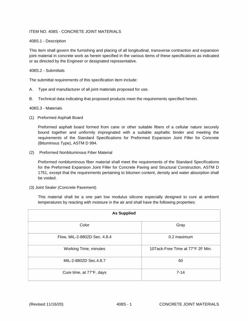
(Revised 11/16/20) 408S - 1 CONCRETE JOINT MATERIALS
ITEM NO. 408S - CONCRETE JOINT MATERIALS
408S.1 - Description
This item shall govern the furnishing and placing of all longitudinal, transverse contraction and expansion
joint material in concrete work as herein specified in the various items of these specifications as indicated
or as directed by the Engineer or designated representative.
408S.2 - Submittals
The submittal requirements of this specification item include:
A. Type and manufacturer of all joint materials proposed for use.
B. Technical data indicating that proposed products meet the requirements specified herein.
408S.3 - Materials
(1) Preformed Asphalt Board
Preformed asphalt board formed from cane or other suitable fibers of a cellular nature securely
bound together and uniformly impregnated with a suitable asphaltic binder and meeting the
requirements of the Standard Specifications for Preformed Expansion Joint Filler for Concrete
(Bituminous Type), ASTM D 994.
(2) Preformed Nonbituminous Fiber Material
Preformed nonbituminous fiber material shall meet the requirements of the Standard Specifications
for the Preformed Expansion Joint Filler for Concrete Paving and Structural Construction, ASTM D
1751, except that the requirements pertaining to bitumen content, density and water absorption shall
be voided.
(3) Joint Sealer (Concrete Pavement)
This material shall be a one part low modulus silicone especially designed to cure at ambient
temperatures by reacting with moisture in the air and shall have the following properties:
As Supplied
Color Gray
Flow, MIL-2-8802D Sec. 4.8.4 0.2 maximum
Working Time, minutes 10Tack-Free Time at 77°F 2F Min.
MIL-2-8802D Sec.4.8.7 60
Cure time, at 77°F, days 7-14

(Revised 11/16/20) 408S - 2 CONCRETE JOINT MATERIALS
As Supplied
Full Adhesion, days 14-21
As Cured—-after 7 days at 77°F and 40% RH
Elongation, percent minimum 1200
Durometer Hardness, Shore A, points ASTM 2240 15
Joint Movement Capability, percent +100/-50
Tensile Strength, maximum elongation, psi 100
Peel Strength, psi 25
The joint sealer shall adhere to the sides of the concrete joint or crack and shall be an effective seal
against infiltration of water and incompressibles. The material shall not crack or break when exposed
to low temperature.
(5) Backer Rod
Backer Rod shall be expanded closed cell polyethylene foam compatible with sealant. No bond or
reaction shall occur between rod and sealant. Backer Rod shall be of sufficient width to be in
compression after placement and shall be used with joint sealer.
(6) Joint Sealing Material
Joint Sealing Material for other than pavement use may be a two-component, synthetic polymer or
cold-pourable, self-leveling type meeting the following requirements:
The material shall adhere to the sides of the concrete joint or crack and shall form an effective seal
against infiltration of water and incompressibles. The material shall not crack or break when exposed
to low temperatures. Curing is to be by polymerization and not by evaporation of solvent or fluxing of
harder particles. It shall cure sufficiently at an average temperature of 77°F 3°F so as not to pick up
under wheels of traffic in a maximum of 3 hours.
Performance Requirements:
When tested in accordance with Test Method Tex-525-C, the joint sealing material shall meet
the above curing times and the requirements as follows:
It shall be of such consistency that it can be mixed and poured or mixed and extruded into joints
at temperatures above 60°F.

(Revised 11/16/20) 408S - 3 CONCRETE JOINT MATERIALS
Penetration 77°F, 150 gm. Cone, 5 sec., max.-cm 0.90
Bond and Extension 75%, 0F, 5 cycles:
Dry Concrete Blocks Pass
Wet Concrete Blocks Pass
Steel Blocks (Primed if specified by manufacturer) Pass
Flow at 200 °F None
Water content % by weight, max. 5.0
Resilience:
Original sample min. % (cured) 50
Oven-aged at 158°F min. % 50
For Class 1-a material only, Cold Flow (10 minute) None
(7) Rebonded Recycled Tire Rubber
This material consists of granular particles of rubber, made by grinding automobile and truck tires,
securely bound together by a synthetic resin or plastic binder. The filler must be molded into sheets
of the required dimensions, which meet the testing requirements of both ASTM D 1751 and ASTM D
1752, except that the requirements for asphalt content and expansion are waived. The density of the
material must be at least 30 lb/ft3.
408S.4 - Construction Methods
The Contractor shall install "Concrete Joint Materials" which will function as a compatible system. Joint
sealer shall not be placed where a bond braker is present.
Asphalt or other materials used shall extend the full depth of the concrete and shall be perpendicular to
the exposed face. All joints shall be shaped to conform to the contour of the finished section in which they
are installed. All material shall be a minimum of 1/2 inch thick or as indicated. Materials shall be anchored
to the adjacent concrete to permanently hold them in place. Joint sealer shall be installed in accordance
with the manufacturer's recommendations.
The material used for curb and gutter expansion joints filler shall conform to any of the above, except
when placed adjacent to concrete pavement, the joint material shall match the pavement joint material.

(Revised 11/16/20) 408S - 4 CONCRETE JOINT MATERIALS
408S.5 - Measurement and Payment
No additional compensation will be made for materials, equipment or labor required by this item, but shall
be included in the unit price bid for the item of construction in which this item is used.
END

(Revised 11/16/20) 409S - 1 MEMBRANE CURING
ITEM NO. 409S - MEMBRANE CURING
409S.1 - Description
This item shall govern curing concrete pavement, concrete base, pavement, curbs, gutters, retards,
sidewalks, driveways, medians, islands, concrete riprap, cement stabilized riprap, concrete structures and
other concrete as indicated by applying an impervious liquid membrane forming material.
409S.2 - Submittals
Within 14 days prior to the commencement of related work, the Contractor shall electronically submit the
following submittal requirements:
A. Type and manufacturer for all membrane curing materials proposed.
B. Proposed curing procedures.
409S.3 - Material
The liquid forming membrane curing compound shall comply with the "Standard Specification for Liquid
Membrane-forming Compounds for Curing Concrete", ASTM C 309, Type 1-D clear or translucent, with
fugitive dye or Type 2 white pigmented. The material shall have a minimum flash point of 80°F when
tested by the "Pensky-Martin Closed Cup Tester", ASTM D 93.
It shall be of such consistency that it can be satisfactorily applied as a fine mist through an atomizing
nozzle by means of approved pressure spraying equipment at atmospheric temperatures above 40°F.
It shall be of such nature that it will not produce permanent discoloration of concrete surfaces nor react
deleteriously with the concrete or its components. Type 1 compound shall contain a fugitive dye that will
be distinctly visible not less than 4 hours nor more than 7 days after application.
Type 2 compound shall not settle out excessively or cake in the container and shall be capable of being
mixed to a uniform consistency by moderate stirring and shall exhibit a daylight reflectance of not less
than 60 percent of that of magnesium oxide when tested as indicated.
The compound shall produce a firm, continuous, uniform moisture impermeable film, free from pinholes
and shall adhere satisfactorily to the surfaces of damp concrete. When applied to the damp concrete
surface at the rate of coverage indicated, the compound shall dry to the touch in not more than 4 hours
and shall not be tacky or track off concrete after 12 hours.
It shall adhere to horizontal and vertical surfaces in a tenacious film and shall not run off or show an
appreciable sag, disintegrate, check, peel or crack during the required curing period.
Under traffic, the compound shall not pick up or peel and shall gradually disintegrate from the surface.
The compound shall be delivered to the job only in the manufacturer's original containers, which shall be
clearly labeled with the manufacturer's name, the trade name of the material and a batch number or
symbol with which test samples may be correlated.
The water retention test shall be in accordance with the following:

(Revised 11/16/20) 409S - 2 MEMBRANE CURING
Percentage loss shall be defined as the water lost after the application of the curing material was applied.
The permissible percentage moisture loss (at the rate of coverage specified herein) shall not exceed the
following:
24 hours after application 2 percent
72 hours after application 4 percent
409S.4 - Construction Methods
The membrane curing compound shall be applied after the surface finishing has been completed and
immediately after the free surface moisture has disappeared. The surface shall be sealed with a single
uniform coating of the specified type of curing compound applied at the rate of coverage recommended
by the manufacturer and directed by the Engineer or designated representative, but not less than 1 gallon
per 180 square feet of area. The Contractor shall provide satisfactory means and facilities to properly
control and check the rate of application of the compound.
The compounds shall not be applied before the surface has become dry but shall be applied just after
free moisture has disappeared.
The compound shall be thoroughly agitated during its use and shall be applied by means of approved
mechanical power pressure sprayers for street and bridge applications. The sprayers used to apply the
membrane to concrete exposed surfaces shall travel at a uniform speed along the forms and be
mechanically driven. The equipment shall be of such design that it will insure uniform and even
application of the membrane material. The sprayers shall be equipped with satisfactory atomizing
nozzles. On small miscellaneous items or on interim bridge deck curing will the Contractor be permitted to
use hand-powered spray equipment. For all spraying equipment, the Contractor shall provide facilities to
prevent the loss of the compound between the nozzle and the concrete surface during the spraying
operations.
At locations where the coating shows discontinuities, pinholes or other defects or if rain falls on the newly
coated surface before the film has dried sufficiently to resist damage, an additional coat of the compound
shall be applied immediately at the same rate of coverage specified herein.
To ensure proper coverage, the Engineer or designated representative shall inspect all treated areas after
application of the compound for the period of time designated in the specification for curing, either for
membrane curing or for other methods. Dry areas are identifiable because of the lighter color of dry
concrete as compared to damp concrete. All suspected areas shall be tested by placing a few drops of
water on the suspected areas. If the water stands in rounded beads or small pools which can be blown
along the surface of the concrete without wetting the surface, the water impervious film is present. If the
water wets the surface of the concrete as determined by obvious darkening of the surface or by visible
soaking into the surface, no water-impervious film is present. Should the foregoing test indicate that any
area during the curing period is not protected by the required water-impervious film an additional coat or
coats of the compound shall be applied immediately and the rate of application of the membrane
compound shall be increased until all areas are uniformly covered by the required water-impervious film.

(Revised 11/16/20) 409S - 3 MEMBRANE CURING
The compounds shall not be applied to a dry surface and if the surface of the concrete has become dry, it
shall be thoroughly moistened prior to the application of the membrane by fogging or mist application.
Sprinkling or coarse spraying will not be allowed.
When temperatures are such as to warrant protection against freezing, curing by this method shall be
supplemented with an approved insulating material capable of protecting the concrete for the specified
curing period.
If at any time there is reason to believe that this method of curing is unsatisfactory or is detrimental to the
work, the Contractor, when notified, shall immediately cease the use of this method and shall change to
curing by one of the other methods specified under this contract.
Curing compounds shall be compatible with the adhesion of toppings or overlays where curing has been
applied to the concrete base surface in order to assure adequate bond.
When forms are stripped before the 4 minimum curing days have passed, curing shall continue by an
approved method.
409S.5 - Measurement and Payment
Membrane curing will not be measured for payment. The work and materials prescribed herein will not be
paid for directly but shall be included in the unit price bid for the item of construction in which these
materials are used.
END

(Revised 11/16/20) 410S - 1 CONCRETE STRUCTURES
ITEM NO. 410S - CONCRETE STRUCTURES
410S.1 - Description
This item shall govern the construction of all types of structures involving the use of structural concrete,
except where the requirements are waived or revised by other governing specifications.
All concrete structures shall be constructed in accordance with the design requirements and details
indicated on the drawings, in conformity with the pertinent provisions of the items contracted for, the
incidental items referred to and in conformity with the requirements herein.
410S.2 - Submittals
Within 14 days prior to the commencement of related work, the Contractor shall submit electronically the
following submittal requirements as applicable:
a. Appropriate mix designs for class of concrete for each type of structure or unit;
b. Appropriate mortar and grout mix designs;
c. Product name, description, technical information and supplier of any acrylic-polymer latex
admixture;
d. Type, supplier and certified test results for expansion joint materials;
e. Type of waterstop and confirmation that the product conforms to TxDOT DMS-6160;
f. Type and manufacturer of proposed evaporation retardant and confirmation that it meets the
requirements of test results for TxDOT DMS-4650;
g. Type and manufacturer of proposed chemical admixtures and confirmation that it meets the
requirements of test results for TxDOT DMS-4640;
h. Type and manufacturer of proposed curing admixtures and confirmation that it meets the
requirements of test results for TxDOT DMS-4640;
i. Type and manufacturer of proposed chemical admixtures and confirmation that it meets the
requirements of test results for TxDOT DMS-4640;
j. Type and manufacturer of proposed epoxy and/or adhesives and confirmation that it meets
the requirements of test results for TxDOT DMS-6100;
k. Reinforcing steel shall conform to Standard Specification Item No. 406S, "Reinforcing Steel".
l. Contractors formwork plan for placing and consolidating concrete around wall penetrations
and at locations designated as having congested reinforcing steel.
410S.3 - Materials
A. Concrete
Concrete shall conform to Item No. 403S, "Concrete for Structures".

(Revised 11/16/20) 410S - 2 CONCRETE STRUCTURES
The class of concrete for each type of structure or unit shall be as indicated on the drawings or by
pertinent governing specifications.
B. Grout or Mortar
When required or shown on the drawings, mortar and grout consisting of 1 part hydraulic cement
and 2 parts sand with sufficient water to provide the desired consistency shall be provided. Mortar
shall be provided with a consistency that can be handled easily and spread by a trowel. Grout shall
be provided with a consistency that will flow into and completely fill all voids.
C. Latex
When required an acrylic-polymer latex admixture (acrylic resin emulsion in accordance with TxDOT
DMS-4640, "Chemical Admixtures for Concrete") suitable for producing polymer-modified concrete
or mortar shall be provided. The latex shall not be allowed to freeze.
The following information shall be submitted for latex:
a. Name and information of company contact personnel,
b. Product name and polymer description, and
The latex shall meet the following requirements.
Table 1: LATEX ADDITIVE REQUIREMENTS
Property Value
Total Solids, minimum, percent 47
PH 9.0 to 11.0
Brookfield viscosity (# 1 spindle @ 10 rpm), mPas, maximum 60
Butadiene Content, percent 30 to 40
Freeze-thaw stability, 2 cycles. maximum 0.1
Specification targets and production tolerances shall also be provided for the following properties.
1. viscosity (including test method and temperature reference),
2. percent solids,
3. pH,
4. specific gravity, and
5. styrene/butadiene ratio.

(Revised 11/16/20) 410S - 3 CONCRETE STRUCTURES
D. Reinforcing Steel
Reinforcing steel shall conform to Standard Specification Item No. 406S, "Reinforcing Steel".
E. Expansion Joint Material
Joints and devices to provide for expansion and contraction shall be constructed as indicated herein
or in the Drawings. The expansion joint material shall conform to the requirements of TxDOT
DMS-6310, "Joint Sealants and Fillers".
1. Preformed Fiber Sheets
Unless otherwise indicated on the drawings preformed bituminous fiber material shall be
provided. The preformed fiber material shall be 1/2 inch or conform to the dimensions
indicated on the drawings. Preformed fiber sheets shall be one of the following unless
otherwise noted on the drawings:
a. “Preformed Bituminous Fiber Material” shall meet the requirements of the Standard
Specifications for Preformed Expansion Joint Filler for Concrete Paving and Structural
Construction, ASTM Designation: D1751.
b. “Preformed Non-Bituminous Fiber Material”: shall meet the requirements of the Standard
Specification for Preformed Expansion Joint Filler for Concrete Paving and Structural
Construction ASTM Designation: D1751, except that the requirements pertaining to
bitumen content, density and water absorption shall be voided.
2. Joint Sealing Material
Unless otherwise indicated on the drawings, the sealer shall be synthetic polymer Sikaflex,
iCSL or approved equivalent.
3. Timber Boards
Timber boards shall be made from redwood or cypress and must be free from sapwood, knots,
clustered bird's eye, checks and splits. When oven dried at 230°F to a constant weight, the
density of the board shall be between 20 and 35 lbs. per cubic foot.
4. Asphalt Board
Asphalt Board shall consist of two liners of 0.016 inches asphalt impregnated paper, filler with
a mastic mixture of asphalt and vegetable fiber and/or mineral filler. Boards shall be smooth,
flat and sufficiently rigid to permit installation. When tested in accordance with Test Method
Tex-524-C, the asphalt board shall not deflect from the horizontal more than one (1) inch in
three and one half (3 ½) inches.
5. Rebonded Neoprene Filler Sheet
Rebonded neoprene filler shall consist of ground closed cell neoprene particles, rebonded and
molded into sheets of uniform thickness of the dimensions indicated on the drawings. These
sheets shall meet the requirements of ASTM D-1752, Type I.
The manufacturer shall furnish the City Engineer or designated representative with certified
test results as to the compliance with the above requirements.

(Revised 11/16/20) 410S - 4 CONCRETE STRUCTURES
F. Waterstop
Unless otherwise indicated on the drawings, rubber waterstops or Polyvinyl Chloride (PVC)
waterstops that conform to TxDOT DMS-6160, "Waterstops, Nylon Reinforced Neoprene Sheet, and
Elastomeric Pads" shall be provided.
G. Evaporation Retardants
Evaporation retardants shall conform to the requirements of TxDOT DMS-4650, "Hydraulic Cement
Concrete Curing Materials and Evaporation Retardants". The evaporation retardant must be a
commercially available monomolecular film compound. The evaporation retardant shall have no
adverse effect on the cement hydration process or the concrete and shall reduce surface moisture
evaporation from the concrete when performing concrete operations in direct sun, wind, high
temperatures, or low relative humidity. The producer of the evaporation retardant shall certify that it
meets these specified requirements.
H. Curing Materials
1. Liquid Membrane Forming compounds
Liquid Membrane Forming compounds shall conform to the requirements of TxDOT
DMS-4650, "Hydraulic Cement Concrete Curing Materials and Evaporation Retardants". The
compound shall be applied to damp concrete as a fine mist through atomizing nozzles at a wet
film thickness of 8 to 9 mils. The liquid membrane-forming compound must not react
deleteriously with concrete or its components. It must produce a firm, continuous, uniform
moisture-impermeable film that is free of pinholes, cracks, or other film defects. It must also
exhibit satisfactory adhesion.
The consistency must be such that the compound can be applied satisfactorily by conventional
or airless spray at atmospheric and material temperatures above 40°F without thinning. When
applied at the manufacturer's recommended thickness, not less than 8 mils wet, to vertical
surfaces of damp concrete, the compound must not run off or appreciably sag. The liquid
membrane-forming compound must not disintegrate, check, peel, or crack during the required
curing period. It must not peel or pick up under traffic and must disappear from the surface of
the cured concrete by gradual disintegration.
2. Cotton Mats
Cotton mats shall consist of a filling material of cotton "bat" or "bats" [at least 12 oz. Per
square yard] completely covered with unsized cloth [at least 6 oz. Per square yard stitched
longitudinally with continuous parallel rows of stitching spaced at less than 4 in., or tuft both
longitudinally and transversely at intervals less than 3 in.
The cotton mats shall be free from tears and in good general condition. A flap at least 6 in.
wide with two (2) thicknesses of the covering that extends along one side of the mat shall be
provided.
3. Polyethylene Sheeting
The polyethylene sheeting shall be at least 4 mils thick and free from visible defects. Clear or
opaque white sheeting shall be provided when the ambient temperature during curing exceeds
60°F or when applicable to control temperature during mass pours.
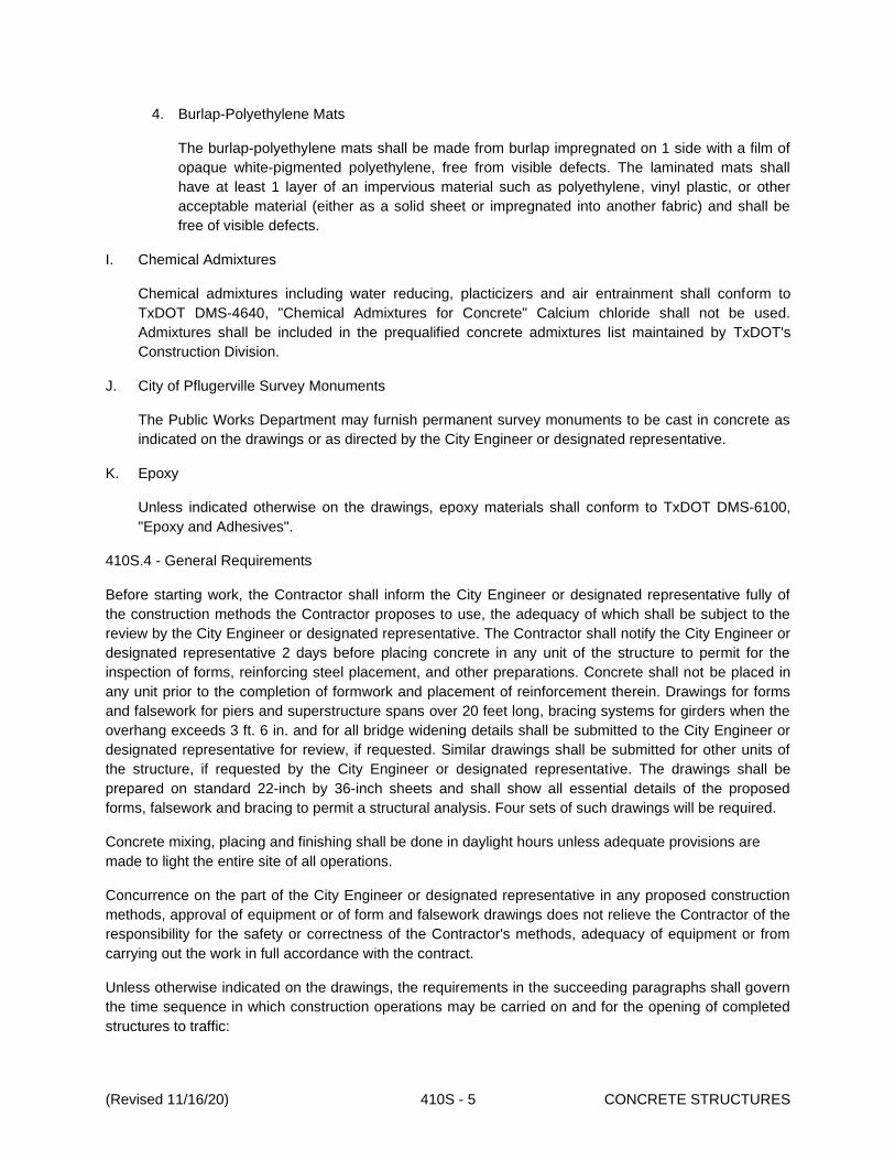
(Revised 11/16/20) 410S - 5 CONCRETE STRUCTURES
4. Burlap-Polyethylene Mats
The burlap-polyethylene mats shall be made from burlap impregnated on 1 side with a film of
opaque white-pigmented polyethylene, free from visible defects. The laminated mats shall
have at least 1 layer of an impervious material such as polyethylene, vinyl plastic, or other
acceptable material (either as a solid sheet or impregnated into another fabric) and shall be
free of visible defects.
I. Chemical Admixtures
Chemical admixtures including water reducing, placticizers and air entrainment shall conform to
TxDOT DMS-4640, "Chemical Admixtures for Concrete" Calcium chloride shall not be used.
Admixtures shall be included in the prequalified concrete admixtures list maintained by TxDOT's
Construction Division.
J. City of Pflugerville Survey Monuments
The Public Works Department may furnish permanent survey monuments to be cast in concrete as
indicated on the drawings or as directed by the City Engineer or designated representative.
K. Epoxy
Unless indicated otherwise on the drawings, epoxy materials shall conform to TxDOT DMS-6100,
"Epoxy and Adhesives".
410S.4 - General Requirements
Before starting work, the Contractor shall inform the City Engineer or designated representative fully of
the construction methods the Contractor proposes to use, the adequacy of which shall be subject to the
review by the City Engineer or designated representative. The Contractor shall notify the City Engineer or
designated representative 2 days before placing concrete in any unit of the structure to permit for the
inspection of forms, reinforcing steel placement, and other preparations. Concrete shall not be placed in
any unit prior to the completion of formwork and placement of reinforcement therein. Drawings for forms
and falsework for piers and superstructure spans over 20 feet long, bracing systems for girders when the
overhang exceeds 3 ft. 6 in. and for all bridge widening details shall be submitted to the City Engineer or
designated representative for review, if requested. Similar drawings shall be submitted for other units of
the structure, if requested by the City Engineer or designated representative. The drawings shall be
prepared on standard 22-inch by 36-inch sheets and shall show all essential details of the proposed
forms, falsework and bracing to permit a structural analysis. Four sets of such drawings will be required.
Concrete mixing, placing and finishing shall be done in daylight hours unless adequate provisions are
made to light the entire site of all operations.
Concurrence on the part of the City Engineer or designated representative in any proposed construction
methods, approval of equipment or of form and falsework drawings does not relieve the Contractor of the
responsibility for the safety or correctness of the Contractor's methods, adequacy of equipment or from
carrying out the work in full accordance with the contract.
Unless otherwise indicated on the drawings, the requirements in the succeeding paragraphs shall govern
the time sequence in which construction operations may be carried on and for the opening of completed
structures to traffic:

(Revised 11/16/20) 410S - 6 CONCRETE STRUCTURES
a. Superstructure members, forms, falsework or erection equipment shall not be placed on the
substructure before the concrete therein has attained a 3000 psi compressive strength.
b. Storage of materials on completed portions of a structure will not be permitted until all curing
requirements for those particular portions have been met.
c. No forms shall be erected on concrete footings supported by piling or drilled shafts until the
concrete therein has attained a minimum compressive strength of 2500 psi. Such work may begin
on spread footings after the therein has aged at least 2 curing days. Concrete may be placed as
soon as the forms and reinforcing steel are approved by the City Engineer or designated
representative.
d. The support of tie beam and/or forms by falsework placed on previously placed tie beams is
permissible provided such beams have attained 3000 psi compressive strength, curing
requirements are completed and the beams are properly supported to eliminate stresses not
provided for in the design.
e. Bridges and direct traffic culverts shall not be opened to construction traffic or to the traveling
public until authorized by the City Engineer or designated representative in accordance with the
following:
f. Authorization may be given after the last slab concrete has been in place at least 14 days for light
construction traffic not to exceed a 3/4-ton vehicle. Authorization to place embankments to allow
normal construction traffic and when necessary to the traveling public, may be given after the last
slab concrete has been in place 30 days or when the minimum compressive strength (fc') has
reached the 28 day strength conforming to Item No. 403S, "Concrete for Structures" or as
indicated on the drawings.
410S.5 - Drains
Weep holes and roadway drains shall be installed and constructed as indicated on the drawings.
410S.6 - Expansion Joints
Joints and devices shall be used to provide for expansion and contraction of concrete slabs and shall be
constructed as indicated on the drawings.
The bearing area under the expansion ends of concrete slabs and slab and girder spans shall be given a
steel trowel finish and finished to the exact grades required on the drawings. The material used to
separate expansion surfaces shall be as indicated on the drawings and placed so that concrete or mortar
cannot be subsequently worked around or under it. The bridging of concrete or mortar around expansion
joint material in bearings and expansion joints shall be prevented.
Concrete adjacent to armor joints and finger joints shall be placed carefully to avoid defective anchorage
and porous or honeycombed concrete in such areas.
All open joints and joints to be filled with expansion joint material shall be constructed using forms
adaptable to loosening or early removal. To avoid expansion or contraction damage to the adjacent
concrete, these forms shall be loosened as soon as possible after final concrete set to permit free
movement of the span without requiring full form removal.

(Revised 11/16/20) 410S - 7 CONCRETE STRUCTURES
Preformed fiber joint material or other material indicated shall be used in the vertical joints of the roadway
slab, curb, median or sidewalk. The top 1-inch thereof shall be filled with joint sealing material, as
specified herein. The sealer shall be installed in accordance with Standard Specification Item No. 413S,
"Cleaning and/or Sealing Joints and Cracks (PC Concrete)" and the manufacturer's recommendations.
Prior to placing the sealing material, the vertical faces of the joint shall be cleaned of all laitance by
sandblasting or by mechanical routing. Cracked or spalled edges shall be repaired. The joint shall be
blown clean of all foreign material and sealed.
Where preformed fiber joint material is used, it shall be anchored to the concrete on one side of the joint
by light wire or nails to prevent the material from falling out.
Finished joints shall conform to the drawing details with the concrete sections completely separated by
the specified opening or joint material.
Soon after form removal and where necessary after surface finishing, all projecting concrete shall be
removed along exposed edges to secure full effectiveness of the expansion joints.
410S.7 - Construction Joints
The joint formed by placing plastic concrete in direct contact with concrete that has attained its initial set
shall be deemed a construction joint. The term monolithic placement shall be interpreted to mean that the
manner and sequence of concrete placing shall not create construction joints.
Construction joints shall be of the type and at the locations indicated on the drawings. Additional joints will
not be permitted without written authorization from the City Engineer or designated representative and
when authorized, shall have details equivalent to those indicated for joints in similar locations.
Unless otherwise provided, construction joints shall be square and normal to the forms. Bulkheads shall
be provided in the forms for all joints, except when horizontal. All vertical construction joints shall be
chamfered. All horizontal construction joints shall be routed or grooved.
Construction joints requiring the use of joint sealing material shall be as indicated on the drawings or as
directed by the City Engineer or designated representative. The material will be indicated on the drawings
without reference to joint type.
A concrete placement terminating at a horizontal construction joint shall have the top surface roughened
thoroughly as soon as practicable after initial set is attained. The surfaces at bulkheads shall be
roughened as soon as the forms are removed.
The hardened concrete surface shall be thoroughly cleaned of all loose material, laitance, dirt or foreign
matter and saturated with water so it is moist when placing fresh concrete against it. Remove all free
water and moisten the surface before concrete or bonding grout is placed against it. Forms shall be
drawn tight against the existing concrete and the joint surface flushed with grout just prior to placing the
fresh concrete.
The joint surface shall be coated with bonding mortar, grout, epoxy or other material as indicated on the
drawings or other items. A Type V epoxy shall be provided in accordance with TxDOT DMS-6100,
"Epoxies and Adhesives" for bonding fresh concrete to hardened concrete. The epoxy shall be placed on
a clean dry surface and the fresh concrete shall be placed while the epoxy is still tacky. Bonding mortar or
grout shall be placed on a surface that is saturated surface dry and the concrete shall be placed before

(Revised 11/16/20) 410S - 8 CONCRETE STRUCTURES
the bonding mortar or grout dries. Other bonding agents shall be placed in accordance with the
manufacturer's recommendations.
410S.8 - Foundation and Substructure
Excavation for foundations and substructure shall conform to Standard Specification Item No. 401S,
"Structural Excavation and Backfill".
Concrete for foundation seals, unless otherwise indicated on the drawings, shall be Class C Concrete
with a coarse aggregate grade of 2, 3, 4 or 5 and placed in accordance with the requirements herein. The
top of the completed seal shall not vary from plan grade or the grade established by the City Engineer or
designated representative.
Where a concrete seal is indicated on the Drawings, the design will be based on the normal water
elevation as indicated on the Drawings. If the foundation concrete can be placed in the dry at the time of
construction, the seal will not be required. If additional seal is necessary for the conditions existing during
the time of construction, its thickness shall be increased as deemed necessary by the Contractor and at
the Contractor's expense. If the conditions existing at the time of construction require a seal for placing
the foundation concrete in the dry and none is indicated on the Drawings, the Contractor shall place an
adequate seal at the Contractor's expense.
The seal shall be allowed to set for at least 36 hours before the caisson or cofferdam is dewatered, after
which the top of the seal shall be cleaned of all laitance or other soft material and all high spots exceeding
the above limitation shall be cut off and removed.
410S.9 - Falsework
The Contractor is totally responsible for all falsework. The Contractor shall design and construct it to
safely carry the maximum anticipated loads and to provide the necessary rigidity. Details of falsework
construction shall be subject to review by the City Engineer or designated representative, but City's
review shall in no way relieve the Contractor of responsibility of the adequacy and safety of the falsework
design.
All timber used in falsework centering shall be sound, in good condition and free from defects which will
impair its strength. When wedges are used to adjust falsework to desired elevations, they shall be used in
pairs to insure even bearing.
Sills or grillages shall be large enough to support the superimposed load without settlement and unless
founded on solid rock, shale or other hard materials, precautions shall be taken to prevent yielding of the
supporting material.
Falsework, which cannot be founded on a satisfactory spread footing, shall be placed on piling driven to a
bearing capacity sufficient to support the superimposed load without settlement. The safe bearing
capacity of piling shall be determined by test loads or by such other methods that may be required or
acceptable to the City Engineer or designated representative.
In general, each falsework bent shall be capped transversely by a member of proper size. A short cap
section forming a T-head may be substituted to permit the removal of portions of the forms without
disturbing the falsework. Caps shall be securely fastened to each pile or column in the bent and set at the
proper elevation to produce, in conjunction with the use of approved wedges or jacks, permanent camber
indicated on the Drawings, plus a construction camber covering allowance for deformation of the forms

(Revised 11/16/20) 410S - 9 CONCRETE STRUCTURES
and falsework. The use of wedges to compensate for incorrectly cut bearing surfaces will not be
permitted. Each falsework bent shall be securely braced to provide the stiffness required with the bracing
securely fastened to each pile or column it crosses.
In setting falsework for arches, allowances shall be made for settlement of falsework, deflection of the
arch and permanent camber. Provision shall be made by suitable wedges, sand jacks or other acceptable
devices for the controlled lowering of falsework when the arch is swung. Falsework may be required to be
placed on jacks to provide for settlement correction during concrete placement.
When the falsework is no longer required, it shall be removed. Falsework piling shall be pulled or cut off
not less than 2 feet below finished ground level. Falsework and piling in a stream, lake or bay shall be
completely removed to a point specified by the City Engineer or designated representative to prevent any
obstruction to the waterway.
410S.10 - Forms
Forms for precast prestressed concrete members and for prestressed piling shall be constructed
conforming to Item No. 424S, "Pre-stressed Concrete Planks".
A. General
Except where otherwise indicated on the drawings, forms may be of either timber or metal.
Forms for round columns exposed to view shall be of steel, except that other materials will be
allowed with written permission of the City Engineer or designated representative.
Forming plans shall be submitted for approval by the City Engineer or designated representative.
Forms shall be designed for the pressure exerted by a liquid weighing 150 pounds per cubic foot.
The rate of placing the concrete shall be taken into consideration in determining the depth of the
equivalent liquid. For job-fabricated forms an additional live load of 50 pounds per square foot shall
be allowed on horizontal surfaces. The maximum unit stresses shall not exceed 125 percent of the
allowable stresses used by the City Engineer or designated representative for the design of
structures.
Formwork for wall and/or column pours equal or exceeding 8 feet shall be designed in accordance
with ACI 347, "Guide to Formwork for Concrete" and sealed by a Registered Civil Engineer Licensed
in the State of Texas, who is experienced in formwork design.
Commercially produced structural units used in formwork shall not exceed the manufacturer's
maximum allowable working load for moment, shear or end reaction. The maximum working load
shall include a live load of 35 pounds per square foot of horizontal form surface and sufficient details
and data shall be submitted for use in checking formwork details for approval.
Forms shall be practically mortar-tight, rigidly braced and strong enough to prevent bulging between
supports and maintained to the proper line and grade during concrete placement. Forms shall be
maintained in a manner that will prevent warping and shrinkage.
Deflections due to cast-in-place slab concrete and railing shown in the dead load deflection diagram
shall be taken into account in the setting of slab forms.
All forms and footing areas shall be cleaned of any extraneous matter before placing concrete.

(Revised 11/16/20) 410S - 10 CONCRETE STRUCTURES
Permission to place concrete will not be given until all of such work is complete to the satisfaction of
the City Engineer or designated representative.
If, at any stage of the work, the forms show signs of bulging or sagging, the portion of the concrete
causing such condition shall be removed immediately, if necessary and the forms shall be reset and
securely braced against further movement.
B. Timber Forms
Lumber for forms shall be properly seasoned, of good quality and free from imperfections, which
would affect its strength or impair the finished surface of the concrete. The lumber used for facing or
sheathing shall be finished on at least 1 side and 2 edges and shall be sized to uniform thickness.
Form or form lumber that will be reused shall be maintained clean and in good condition. Lumber
that is split, warped, bulged, or marred or that has defects that will produce inferior forms shall not be
used but shall be removed from the work.
Form lining will be required for all formed surfaces, except for the inside of culvert barrels, inlets,
manholes and box girders, the bottom of bridge decks between beams or girders, surfaces that are
subsequently covered by backfill material or are completely enclosed and any surface formed by a
single finished board. Lining will not be required when plywood forms are used.
Form lining shall be of an approved type such as Masonite or plywood. Thin membrane sheeting
such as polyethylene sheets shall not be used for form lining.
Forms may be constructed of plywood not less than 3/4 inch in thickness, with no form lining
required. The grain of the face plies on plywood forms shall be placed parallel to the span between
the supporting studs or joists.
Plywood used for forming surfaces, which remain exposed, shall be equal to that specified as B-B
Plyform Class I or Class II Exterior of the U.S. Department of Commerce Voluntary Product
Standard, PS 1.
Studs and joists shall be spaced so that the facing form material remains in true alignment under the
imposed loads.
Wales shall be spaced close enough to hold forms securely to the designated lines and scabbed at
least 4 feet on each side of joints to provide continuity. A row of wales shall be placed near the
bottom of each placement.
Facing material shall be placed with parallel and square joints and securely fastened to supporting
studs.
Forms for surfaces receiving only an ordinary finish and exposed to view shall be placed with the
form panels symmetrical, i.e., long dimensions set in the same direction. Horizontal joints shall be
continuous.
Molding specified for chamfer strips or other uses shall be made of materials of a grade that will not
split when nailed and which can be maintained to a true line without warping. Wood molding shall be
mill cut and dressed on all faces. Unless indicated otherwise on the drawings, forms shall be filleted
at all sharp corners and edges with triangular chamfer strips measuring 3/4 inch on the sides.

(Revised 11/16/20) 410S - 11 CONCRETE STRUCTURES
Forms for railings and ornamental work shall be constructed to standards equivalent to first class
millwork. All moldings, panel work and bevel strips shall be straight and true with neatly mitered
joints designed so the finish work is true, sharp and clean cut. All forms shall be constructed to
permit their removal without marring or damaging the concrete. The forms may be given a slight
draft to permit ease of removal.
Metal form ties of an approved type or a satisfactory substitute shall be used to hold forms in place
and shall be of a type that permits ease of removal of the metal as hereinafter specified.
All metal appliances used inside of forms for alignment purposes shall be removed to a depth of at
least 1/2 inch from the concrete surface. They shall be made so the metal may be removed without
undue chipping or spalling and when removed, shall leave a smooth opening in the concrete
surface. Burning off of rods, bolts or ties will not be permitted.
Any wire ties used shall be cut back at least 1/2 inch from the face of the concrete and properly
patched.
Devices holding metal ties in place shall be capable of developing the strength of the tie and
adjustable to allow for proper alignment.
Metal and wooden spreaders, which are separate from the forms, shall be removed entirely as the
concrete is being placed.
Adequate clean-out openings shall be provided for narrow walls and other locations where access to
the bottom of the forms is not readily attainable.
Prior to placing concrete, the facing of all forms shall be treated with oil or other bond breaking
coating of such composition that it will not discolor or otherwise injuriously affect the concrete
surface. Care shall be exercised to prevent coating of the reinforcing steel.
C. Metal Forms
The foregoing requirements for timber forms as regards design, mortar-tightness, filleted corners,
beveled projections, bracing, alignment, removal, reuse and wetting shall also apply to metal forms,
except that these will not require lining, unless specifically indicated on the drawings.
The thickness of form metal shall be as required to maintain the true shape without warping or
bulging. All bolt and rivet heads on the facing sides shall be countersunk. Clamps, pins or other
connecting devices shall be designed to hold the forms rigidly together and to allow removal without
injury to the concrete. Metal forms, which do not present a smooth surface or line up properly, shall
not be used. Metal shall be kept free from rust, grease or other foreign materials.
D. Form Supports for Overhang Slabs
Form supports which transmit a horizontal force to a steel girder or beam or to a prestressed
concrete beam will be permitted, but shall not be used unless a structural analysis has been made of
the effect on the girder or beam and approval is granted by the City Engineer or designated
representative.
In normal or skewed spans with standard overhangs not exceeding 3 feet, 1 ½ inches, beam bracing
as shown in the drawings shall be used.

(Revised 11/16/20) 410S - 12 CONCRETE STRUCTURES
Spans in which the overhang width exceeds 3 feet, 1½ inches will require additional support for the
outside beams to resist torsion. Details of the Contractor's proposed method of providing additional
support shall be included with the slab forming plans submitted to the City Engineer or designated
representative for review and approval.
Holes in steel members for support of overhang brackets may be punched or drilled full size or may
be torch cut to 1/4 inch under size and reamed full size. In no case shall the holes be burned full
size. The hole shall be left open unless indicated to be filled with a button head bolt. They shall
never be filled by welding.
410S.11 - Placing Reinforcement
Reinforcement in concrete structures shall be placed carefully and accurately and rigidly supported as
provided in Standard Specification Item No. 406S, "Reinforcing Steel". Reinforcing steel supports shall
not be welded to I-beams or girders or stirrups of prestressed concrete beams.
410S.12 - Placing Concrete
A. General
Concrete shall not be placed when impending weather conditions would impair the quality of the
finished work. If conditions of wind, humidity and temperature are such that concrete cannot be
placed without the potential for shrinkage cracking, the concrete should be placed in early morning,
at night or on a schedule with more favorable weather. When mixing, placing and finishing concrete
is scheduled during non-daylight hours; the entire placement site should be illuminated to the
satisfaction of the City Engineer or designated representative.
If changes in weather conditions require protective measures after work starts, adequate shelter
shall be provided to protect the concrete against damage from rainfall or from freezing temperatures
as outlined in this Item. Operations during rainfall shall only be continued if approved by the City
Engineer or designated representative. Aggregate stockpiles shall be covered to the extent
necessary to control the moisture conditions in the aggregates.
Slab concrete shall be mixed in a plant located off the structure. Carting or wheeling concrete
batches over completed slabs will not be permitted until they have aged at least 4 full curing days or
timber planking placed on top of the slab for the carts to traverse along. Carts shall be equipped with
pneumatic tires. Curing operations shall not be interrupted for the purpose of wheeling concrete over
finished slabs.
Exposed concrete surfaces, while still plastic, shall be stamped with an impression having the
Contractor's name, the month and year. The stamp shall be of an approved design.
At least 1 day of curing shall be allowed after the concrete has achieved initial set before placing
strain on projecting reinforcement to prevent damage to the concrete.
The storing of reinforcing or structural steel on completed roadway slabs generally shall be avoided
and when permitted, shall be limited to quantities and distribution that will not induce excessive
stresses.

(Revised 11/16/20) 410S - 13 CONCRETE STRUCTURES
B. Preparation of Surfaces
All forms, prestressed concrete panels, T-beams and concrete box beams on which concrete will be
placed shall be thoroughly wetted before the placement of concrete. Puddles of excess water shall
be removed before placing the concrete. The various surfaces shall be in a moist, saturated surface
dry condition when concrete is placed on or against them.
The subgrade or foundation shall be moist before placing concrete for bridge approach slabs or
other concrete placed on grade. If dry the subgrade shall be lightly sprinkled.
C. Placing Temperature
The minimum temperature of all concrete at the time of placement shall not be less than 50°F. The
maximum temperature of any concrete, unless otherwise indicated on the drawings, shall not exceed
95°F when placed. The maximum temperature of cast-in-place concrete in bridge superstructures,
diaphragms, parapets, concrete portions of railing, curbs and sidewalks and direct traffic box culverts
shall not exceed 85°F when placed. Other portions of structures, when indicated on the drawings,
shall require the temperature control specified.
For continuous placement of the deck on continuous steel units, the initial set of the concrete shall
be retarded sufficiently to ensure that it remains plastic in not less than 3 spans immediately
preceding the one being placed. For simple spans, retardation shall be required only if necessary to
complete finishing operations.
The consistency of the concrete as placed should allow the completion of all finishing operations
without the addition of water to the surface. When conditions are such that additional moisture is
needed for finishing, the required water shall be applied to the surface by fog spray only and shall be
held to a minimum amount. Fog spray for this purpose may be applied with hand operated fogging
equipment.
The height of free fall of concrete shall be limited to 5 feet to prevent segregation.
D. Transporting Time
The maximum time interval between the addition of cement to the batch and the placing of concrete
in the forms shall not exceed the following:
Table 2: Allowable Transportation Times
Air or Concrete Temperature
whichever is higher
Maximum Time w/o
Retarder
Maximum Time with Retarder
*Specific
Applications
All others
Non-agitated Concrete
35°F to 79°F 45 minutes 45 minutes 45 minutes
Over 80°F 30 minutes 45 minutes 45 minutes
Agitated Concrete

(Revised 11/16/20) 410S - 14 CONCRETE STRUCTURES
90°F or above 45 minutes 75 minutes 105 minutes
75°F to 89°F 60 minutes 90 minutes 120 minutes
35°F to 74°F 90 minutes 120 minutes 150 minutes
* Specific applications include Bridge decks, cased drilled shafts and slabs of direct traffic culverts
The use of an approved retarding agent in the concrete will permit the extension of each of the
above temperature-time maximums by 30 minutes for bridge decks, top slabs of direct traffic culverts
and cased drilled shafts and 1 hour for all other concrete except that the maximum time shall not
exceed 45 minutes for non-agitated concrete.
E. Handling and Placing
The Contractor shall give the City Engineer or designated representative 2 days’ notice before
placing concrete in any unit of the structure to permit the review of forms, reinforcing steel placement
and other preparations. Concrete shall not be placed in any unit prior to the completion of formwork
and placement of reinforcement therein.
The sequence for placing concrete shall be as indicated on the drawings or as required herein. The
placing shall be regulated so the pressures caused by the plastic concrete shall not exceed the
loads used in the form design.
The method of handling, placing and consolidation of concrete shall be capable of maintaining the
rate of placement approved by the City Engineer, minimize segregation and displacement of the
reinforcement and produce a uniformly dense and compact mass. Concrete shall not have a free fall
of more than 5 feet, except in the case of drilled shafts, thin wall sections such as in culverts, or as
allowed by other Items. Any hardened concrete spatter ahead of the plastic concrete shall be
removed.
Each part of the forms shall be filled by depositing concrete as near its final position as possible. The
coarse aggregate shall be worked back from the face and the concrete forced under and around the
reinforcement bars without displacing them. Depositing large quantities at one point and running or
working it along the forms will not be allowed.
Concrete shall be deposited in the forms in layers of suitable depth but not more than 36 inches in
thickness, unless otherwise directed by the City Engineer or designated representative.
Cold joints in a monolithic placement shall be avoided. The sequence of successive layers or
adjacent portions of concrete shall be such that they can be vibrated into a homogeneous mass with
the previously placed concrete without a cold joint. Not more than 1 hour (1 ½ hours if a normal
dosage of retarding admixture is used) shall elapse between adjacent or successive placements of
concrete. Unauthorized construction joints shall be avoided by placing all concrete between the
authorized joints in one continuous operation.
An approved retarding agent shall be used to control stress cracks and/or authorized cold joints in
mass placements where differential settlement and/or setting time may induce stress cracking, such
as on false work, in deep girder stems, etc.
Openings in forms shall be provided, if needed, for the removal of laitance or foreign matter of any
kind.

(Revised 11/16/20) 410S - 15 CONCRETE STRUCTURES
All forms shall be wetted thoroughly before the concrete is placed therein.
F. Consolidation
All concrete shall be well consolidated, and the mortar flushed to the form surfaces by continuous
working with immersion type vibrators. Vibrators which operate by attachment to forms or
reinforcement will not be permitted, except on steel forms. At least 1 standby vibrator shall be
provided for emergency use in addition to the ones required for placement. For lightweight concrete,
vibrators of the high frequency type, which produce a minimum of 7000 impulses per minute, will be
required.
The concrete shall be vibrated immediately after deposition. Prior to the beginning of work, a
systematic spacing of the points of vibration shall be established to insure complete consolidation
and thorough working of the concrete around the reinforcement, embedded fixtures and into the
corners and angles of the forms. Immersion type vibrators shall be inserted vertically, at points 18 to
30 inches apart and slowly withdrawn. The vibrator may only be inserted in a sloping or horizontal
position in shallow slabs. The entire depth of each lift shall be vibrated, allowing the vibrator to
penetrate several inches into the preceding lift. The vibrator shall not be used to move the concrete
to other locations. In addition, the vibrator shall not be dragged through the concrete. Concrete along
construction joints shall be thoroughly consolidated by operating the vibrator along and close to but
not against the joint surface. The vibration shall continue until thorough consolidation and complete
embedment of reinforcement and fixtures is produced, but not long enough to cause segregation.
Vibration may be supplemented by hand spading or rodding, if necessary, to insure the flushing of
mortar to the surface of all forms.
G. Finishing
From the time of initial strike off until final finish is completed and required interim curing is in place,
the unformed surfaces of slab concrete in bridge decks and top slab of direct traffic culverts and
concrete slabs, shall be kept damp, not wet, to offset the effects of rapid evaporation of mixing water
from the concrete due to wind, temperature, low humidity or combinations thereof. Fogging
equipment capable of applying water in the form of a fine fog mist, not a spray, will be required.
Fogging will be applied at the times and in the manner directed by the City Engineer or designated
representative.
Fogging equipment may be either water pumped under high pressure or a combination of air and
water, either system in combination with a proper atomizing nozzle. The equipment shall be
sufficiently portable for use in the direction of any prevailing winds. The equipment shall be adapted
for intermittent use to prevent excessive wetting of the surfaces.
Upon completion of the final finish, interim curing will be required for slab concrete in bridge decks
and top slabs of direct traffic culverts as follows:
a. Required water curing shall begin as soon as it can be done without damaging the concrete
finish.
b. Unless otherwise indicated on the Drawings, Type 1-D membrane curing compound (resin
base only) shall be applied to the slab surface.
H. Installation of Dowels and Anchor Bolts

(Revised 11/16/20) 410S - 16 CONCRETE STRUCTURES
Dowels and anchor bolts shall be installed by casting them in place or by grouting with grout, epoxy,
or epoxy mortar unless indicated otherwise on the drawings.
Holes for grouting shall be formed or drilled. Holes for anchor bolts shall be drilled to accommodate
the bolt embedment required on the drawings. Holes for dowels shall be made at least 12 in. deep
unless indicated otherwise on the drawings. When grout or epoxy mortar is specified the diameter of
the hole shall be at least twice the dowel or bolt diameter but shall not exceed the dowel or bolt
diameter plus 1 ½ in. When epoxy is specified the hole diameter should be 1/16 to 1/4 in. greater
than the dowel or bolt diameter.
Holes for anchor bolts in piers, abutments, bents or pedestals may be drilled or formed by the
insertion of oiled wooden plugs or metal sleeves in the plastic concrete. Formed holes shall be large
enough to permit horizontal adjustments of the bolts. The bolts shall be carefully set in mortar. In lieu
of the above, anchor bolts may be set to exact locations when the concrete is placed.
The holes shall be thoroughly cleaned of all loose material, oil, grease or other bond-breaking
substance and blow them clean with filtered compressed air. When an epoxy type material is used
the holes shall be in a surface dry condition. When hydraulic cement grout is used the holes shall be
in a surface moist condition. The void space between the hole and the dowel or bolt shall be
completely filled with grouting material. The requirements for cleaning outlined in the product
specification for prepackaged systems shall be followed exactly.
The following should be used as a guide in selection of an appropriate grout, mortar, epoxy or epoxy
grout.
Table 3: Guide for Selection of Epoxy, Epoxy Mortar, Grout and Epoxy Grout
Material Type Recommendation
Epoxy, Epoxy Mortar or
other prepackaged Mortar As Approved
Cast-in-place or Grouted
system
1 part hydraulic cement, 2 parts sand and sufficient water for desired
consistency
Neat Epoxy Type III epoxy per TxDOT DMS-6100, "Epoxies and Adhesives"
Epoxy Grout
Type III epoxy per TxDOT DMS-6100, "Epoxies and Adhesives" Provide
grout, epoxy or epoxy mortar as the binding agent unless otherwise
indicated on the drawings
410S.13 - Placing Concrete in Cold Weather
A. General
The Contractor is responsible for the protection of concrete placed under any and all weather
conditions and is responsible for producing concrete equal in quality to that placed under normal

(Revised 11/16/20) 410S - 17 CONCRETE STRUCTURES
conditions. Permission given by the City Engineer or designated representative to allow placement
of the concrete during cold weather does not relieve the Contractor of the responsibility for producing
concrete equal in quality to that placed under normal conditions. Concrete placed under adverse
weather conditions that proves to be unsatisfactory shall be removed and replaced at Contractor'
expense.
B. Cast-in-Place Concrete
Concrete may be placed when the ambient temperature is not less than 35°F in the shade and rising
or above 40°F. Concrete shall not be placed when the ambient temperature in the shade is below
40°F and falling unless approved by the City Engineer or designated representative. Concrete shall
not be placed in contact with any material coated with frost or having a temperature less than 32°F.
Aggregates shall be free from ice, frost and frozen lumps. When required, in order to produce the
minimum specified concrete temperature; the aggregate and/or the water shall be heated uniformly,
in accordance with the following:
The water temperature shall not exceed 180°F and/or the aggregate temperature shall not exceed
150°F. The heating apparatus shall heat the mass of aggregate uniformly. The temperature of the
mixture of aggregates and water shall be between 50°F and 85°F before introduction of the cement.
All concrete shall be effectively protected as follows:
1. The temperature of slab concrete of all unformed surfaces shall be maintained at 50°F or
above for a period of 72 hours from time of placement and above 40°F for an additional 72
hours.
2. The temperature at the surface of all concrete in bents, piers, culvert walls, retaining walls,
parapets, wingwalls, bottom of slabs and other similar forms shall be maintained at 40°F or
above for a period of 72 hours from time of placement.
3. The temperature of all concrete, including the bottom slabs of culverts placed on or in the
ground, shall be maintained above 32°F for a period of 72 hours from time of placement.
Protection shall consist of providing additional covering, insulated forms or other means and
if necessary, supplementing such covering with artificial heating. Avoid applying heat directly
to concrete surfaces. Curing shall be provided during this period until all requirements for
curing have been satisfied.
When impending weather conditions indicate the possibility of the need for such temperature
protection, all necessary heating and covering material shall be on hand ready for use
before permission is granted to begin placement.
Sufficient extra test specimens will be made and cured with the placement to ascertain the
condition of the concrete as placed prior to form removal and acceptance.
C. Precast Concrete
A fabricating plant for precast products which has adequate protection from cold weather in the form
of permanent or portable framework and covering, which protects the concrete when placed the
forms and is equipped with approved steam curing facilities may place concrete under any low
temperature conditions provided:

(Revised 11/16/20) 410S - 18 CONCRETE STRUCTURES
1. The framework and covering are placed, and heat is provided for the concrete and the forms
within 1 hour after the concrete is placed. This shall not be construed to be 1 hour after the
last concrete is placed, but that no concrete shall remain unprotected longer than 1 hour.
2. Steam heat shall keep the air surrounding the concrete between 50°F and 85°F for a
minimum of 3 hours prior to beginning the temperature rise, which is required for steam
curing.
410S.14 - Placing Concrete in Hot Weather
When the temperature of the air is above 85°F, an approved retarding agent will be required in all
exposed concrete, concrete used in superstructures, top slabs of direct traffic culverts and all cased
drilled shafts regardless of temperatures. Concrete mix temperatures shall not exceed 90°F except for
mixes that include high range water reducers where a maximum mix temperature of 100°F will be
allowed.
If the concrete mix temperature is expected to exceed 90°F (or 100°F in mixes with high range water
reducers) ice may be utilized to lower the concrete mix temperature. Ice may be added to the concrete
mix as a portion by weight of the mix water. However, the addition of ice shall not exceed 50% of the total
mix water weight.
When weather conditions are such that the addition of ice at 50% of the mix water is not sufficient to
reduce the concrete mix temperature to an acceptable temperature, concrete work shall not be allowed.
When ice is to be used in hot weather concrete placement, the Contractor shall furnish a mix design
(Section 4.4 of Standard Specification Item 360S, "Concrete Pavement" and Section 6 of Standard
Specification Item No. 403S, "Concrete for Structures") acceptable to the City Engineer or designated
representative for class of concrete specified on the drawings.
410S.15 - Placing Concrete in Water
Concrete shall be deposited in water only when indicated on the drawings or with written permission of
the City Engineer or designated representative. The forms, cofferdams or caissons shall be sufficiently
tight to prevent any water current passing through the space in which the concrete is being deposited.
Pumping will not be permitted during the concrete placing nor until it has set for at least 36 hours.
The concrete shall be placed with a tremie, pump or other approved method and shall not be permitted to
fall freely through the water nor shall it be disturbed after it has been placed. Its surface shall be kept
approximately level during placement.
The tremie shall be supported or the pump operated so that it can be easily moved horizontally to cover
all the work area and vertically to control the concrete flow. The lower end of the tremie or pump hose
shall be submerged in the concrete at all times.
The placing operations shall be continuous until the work is complete.
For concrete to be placed under water, the concrete mix shall be designed in accordance with Standard
Specification Item No. 403S, "Concrete For Structures" with a minimum cement content of 650 lb. Per
cubic yard. An anti-wash admixture may be included in the mix design as necessary to produce a
satisfactory finished product.

(Revised 11/16/20) 410S - 19 CONCRETE STRUCTURES
410S.16 - Placing Concrete in Box Culverts
In general, construction joints will be permitted only where indicated on the drawings.
Where the top slab and walls are placed monolithically in culverts more than 4 feet in clear height, an
interval of not less than 1 nor more than 2 hours shall elapse before placing the top slab to allow for
settlement and shrinkage in the concrete wall.
The base slab shall be trowel finished accurately at the proper time to provide a smooth uniform surface.
Top slabs, which carry traffic, shall be finished as specified for roadway slabs in "Finish of Roadway
Slabs", below. Top slabs of fill type culverts shall be given a reasonably smooth float finish.
410S.17 - Placing Concrete in Foundations and Substructure
Concrete shall not be placed in footings until the depth and character of the foundation has been
inspected by the City Engineer or designated representative and permission has been given to proceed.
Placing of concrete footings upon seal courses will be permitted after the caissons or cofferdams are free
from water and the seal course cleaned. Any necessary pumping or bailing during the concrete
placement shall be done from a suitable sump located outside the forms.
All temporary wales or braces inside cofferdams or caissons shall be constructed or adjusted as the work
proceeds to prevent unauthorized construction joints in footings or shafts.
When footings can be placed in a dry excavation without the use of cofferdams or caissons, forms may
be omitted if desired by the Contractor and approved by the City Engineer or designated representative
and the entire excavation filled with concrete to the elevation of the top of footing.
Concrete in columns shall be placed monolithically unless otherwise indicated on the drawings. Columns
and caps and/or tie beams supported thereon may be placed in the same operation or separately. To
allow for settlement and shrinkage of the column concrete, it shall be placed on the lower level of the cap
or tie beam and placement delayed for not less than 1 hour nor more than 2 before proceeding with the
cap or tie beam placement.
410S.18 - Treatment and Finishing of Horizontal Surfaces Except Bridge Slabs
All unformed upper surfaces shall be struck off to grade and finished. The use of mortar topping for
surfaces under this classification will not be permitted.
After the concrete has been struck off, the surface shall be floated with a suitable float. Bridge sidewalks
shall be given a wood float or broom finish or may be striped with a brush as specified by the City
Engineer or designated representative.
The tops of caps and piers between bearing areas shall be sloped slightly from the center toward the
edge and the tops of abutments and transition bents sloped from the back wall to the edge, as directed by
the City Engineer or designated representative, so that water will drain from the surface. The concrete
shall be given a smooth trowel finish. Bearing areas for steel units shall be constructed in such a manner
to have a full and even bearing upon the concrete. When the concrete is placed below grade, bearing
areas may be raised to grade on beds of Portland cement mortar consisting of 1 part cement, 2 parts
sand and a minimum amount of water.

(Revised 11/16/20) 410S - 20 CONCRETE STRUCTURES
Bearing seat buildups or pedestals for concrete units shall be cast integrally with the cap or with a
construction joint. The construction joint area under the bearing shall have the surface roughened
thoroughly as soon as practical after initial set is obtained. The bearing seat buildups shall be placed
using a latex based grout, an epoxy grout, or an approved proprietary bearing mortar, mixed in
accordance with the manufacturer's recommendation. Pedestals shall be placed using Class C concrete,
reinforced as indicated on the drawings.
The bearing area under the expansion end of concrete slabs and slab and girder spans shall be given a
steel-trowel finish to the exact grades required on the drawings. Bearing areas under elastomeric bearing
pads or nonreinforced bearing seat buildups shall be given a textured wood float finish. The bearing area
shall not vary from a level plane more than 1/16 in. in all directions.
410S.19 - Placing Survey Monuments
The Contractor shall obtain City Survey Monuments, for a fee of 10 dollars, from the Department of Public
Works, Construction Inspection Division. Monuments shall be embedded in freshly poured concrete at
locations indicated on the drawings and accessible to survey equipment at the completion of the project.
The monuments shall be installed flush with the adjacent concrete.
410S.20 - Curing Concrete
The Contractor shall inform the City Engineer or designated representative fully of the methods and
procedures proposed for curing, shall provide the proper equipment and material in adequate amounts
and shall have the proposed method, equipment and material approved by the City Engineer or
designated representative prior to placing concrete.
Inadequate curing and/or facilities therefore shall be cause for the City Engineer or designated
representative to notify the Contractor, in writing, that the work is unsatisfactory, and the concrete will
have to be removed and replaced.
All concrete shall be cured for a period of 4 curing days except as noted herein. A curing day is a
calendar day when the temperature, taken in the shade away from artificial heat is above 50°F for at least
19 hours or on colder days if the temperature of all surfaces of the concrete is maintained above 40°F for
the entire 24 hours. The required curing shall begin when all concrete has attained its initial set. TxDOT's
Tex-440-A, "Initial Time-of-Set of Fresh Concrete" may be used to establish when the concrete has
attained its initial set.
Table 4: Exceptions to 4-Day Curing
Description Type of Cement Required
Curing Days
Upper Surfaces of Bridge Slabs,
Top Slabs of Direct Traffic
Culverts and Concrete Overlays
I or II 8
II or I/II 10
All types with
supplementary
cementing materials
10
Concrete Piling buildups 6

(Revised 11/16/20) 410S - 21 CONCRETE STRUCTURES
For upper surfaces of bridge slabs, bridge support slabs, median and sidewalk slabs and culvert top slabs
constructed using Class S Concrete (Standard Specification Item No. 403S, "Concrete for Structures")
interim curing using a Type 1-D curing compound shall be applied as soon as possible after application of
the evaporation retardant and after the water sheen has disappeared, but no more than 45 minutes after
application of the evaporation retardant. Membrane interim curing shall be applied using a work bridge or
other approved apparatus to ensure a uniform application. Final curing with water cure in accordance with
this section shall start as soon as possible without damaging the surface finish. Water curing shall be
maintained for the duration noted in the table above. Polyethylene sheeting, burlap-polyethylene blankets,
laminated mats or insulating curing mats shall be placed in direct contact with the slab when the ambient
temperature is expected to drop below 40°F during the first 72 hours of the curing period. The curing
materials will be weighed down with dry mats to maintain direct contact with the concrete and to provide
insulation against cold weather. Supplemental heating or insulation may be required in cold and wet
weather if the insulating cotton mats become wet or if the concrete temperature drops below the specified
curing temperature. Application of heat directly to concrete surfaces shall be avoided.
For the top surface of any concrete unit upon which concrete is to be placed and bonded at a later date
(i.e. stub walls, risers, etc.), only water-cure in accordance with this Section shall be used.
All other concrete shall be cured as specified in pertinent Items.
The following methods are permitted for curing concrete subject to the restrictions of this Item:
A. Form Curing
When forms are left in intimate contact with the concrete, other curing methods will not be
required except for exposed surfaces and for cold weather protection.
When forms are striped before the 4-day minimum curing time has elapsed, curing shall continue
by an approved method.
B. Water Curing
All exposed surfaces of the concrete shall be kept wet continuously for the required curing time.
The water used for curing shall meet the requirements for concrete mixing water as indicated in
Item No. 403S, "Concrete for Structures". Seawater will not be permitted. Water, which stains or
leaves an unsightly residue, shall not be used.
1. Wet Mats
Wet cotton mats placed in direct contact with the slab shall be maintained for the required
curing time. If needed damp burlap blankets made from 9-ounce stock may be placed on the
damp concrete surface for temporary protection prior to the application of the cotton mats,
which may be placed dry and wetted down after placement.
The mats shall be weighted down adequately to provide continuous contact with all concrete
surfaces where possible. The surfaces of the concrete shall be kept wet for the required
curing time. Surfaces, which cannot be cured by contact, shall be enclosed with mats,
anchored positively to the forms or to the ground, so that outside air cannot enter the
enclosure. Sufficient moisture shall be provided inside the enclosure to keep all surfaces of
the concrete wet.

(Revised 11/16/20) 410S - 22 CONCRETE STRUCTURES
2. Water Spray
This method shall consist of overlapping sprays or sprinklers that keep all unformed
surfaces continuously wet.
3. Ponding
This method requires the covering of the surfaces with a minimum of 2 inches of clean
granular material, kept wet at all times or a minimum of 1 inch depth of water. Satisfactory
provisions shall be made to provide a dam to retain the water or saturated granular material.
C. Membrane Curing
Unless otherwise indicated on the drawings, either Type 1-D or Type 2 membrane curing
compound may be used where permitted except that Type 1-D (Resin Base Only) will be
permitted for slab concrete in bridge decks and top slabs of direct traffic culverts and all other
surfaces that require a higher grade of surface finish. For substructure concrete, only one Type of
curing compound will be permitted on any one structure.
TABLE 5
REQUIRED PERMITTED
STRUCTURE UNIT DESCRIPTION
Water for
Complete
Curing
Membrane
for Interim
Curing
Water for
Complete
Curing
Membrane
for Complete
Curing
1. Upper surfaces of Bridge Roadway,
Median and Side walk Slabs, Top Slabs of
Direct Traffic, and Culverts.
X X (resin base)
2.Top Surface of any Concrete Unit upon
which Concrete is to be placed and bonded
at a later interval (Stub Walls, Risers, etc.).
Other Super-structure Concrete (curbs,
wing- walls, Parapet Walls, etc.).
X *X *X
3. Top Surface of Precast and/or Pre-
stressed Piling. X X
4. All Substructure Concrete Culverts. Box
Sewers, Inlets, Manholes, Retaining Walls,
Riprap.
*X *X
* Polyethylene Sheeting, Burlap-Polyethylene Mats or Laminated Mats in close intimate contact with the
concrete surfaces, will be considered equivalent to water or membrane curing for items under 4.

(Revised 11/16/20) 410S - 23 CONCRETE STRUCTURES
The membrane curing shall be applied just after free moisture has disappeared in a single, uniform
coating at the rate of coverage recommended by the manufacturer and as approved by the City
Engineer or designated representative, but not less than 1 gallon per 180 square feet of area. Tests
for acceptance shall be at this specified rate.
Membrane curing shall not be applied to dry surfaces but shall be applied just after free moisture has
disappeared. Formed surfaces and surfaces which have given a first rub shall be dampened and
shall be moist at the time of application of the membrane.
When membrane is used for complete curing, the film shall remain unbroken for the minimum curing
period specified. Membrane, which is damaged, shall be corrected immediately by reapplication of
membrane. Polyethylene sheeting, burlap-polyethylene mats or laminated mats in close intimate
contact with the concrete surfaces, will be considered equivalent to membrane curing. Unless
otherwise indicated on the drawing, the choice of membrane type shall be at the option of the
Contractor, except that the City Engineer or designated representative may require the same curing
method for like portions of a single structure.
410S.21 - Removal of Forms and Falsework
Unless otherwise indicated on the drawing, forms for vertical surfaces may be removed when the
concrete has aged 12 hours after initial set, provided it can be done without damage to the concrete.
Forms for mass concrete placements shall be maintained in place for 4-days following concrete
placement. Mass placements are defined as concrete placements with a least dimension greater than
equal to 5 ft., or those designated as such on the drawings.
Forms for inside curb faces may be removed in approximately 3 hours provided it can be done without
damage to the curb.
Unless indicated otherwise on the drawings weight supporting forms and falsework spanning more than
1 ft. for structures, bridge components and culvert slabs shall remain in place until the concrete has
attained a minimum compressive strength of 2500 psi. Forms for other structural components may be
removed as specified by the City Engineer or designated representative.
Inside forms (walls and top slabs) for inlets, box culverts and sewers may be removed after the concrete
has attained a minimum compressive strength of 1800 psi, provided an overhead support system,
approved by the City Engineer or designated representative, is used to transfer the weight of the top slab
to the walls of the box culvert or sewer before the support provided by the forms is removed.
If all test cylinders made for the purpose of form removal have been broken without attaining the required
strength, forms shall remain in place for a total of 14 curing days.
The above provisions relative to form removal shall apply only to forms or parts thereof which are
constructed to permit removal without disturbing forms or falsework required to be left in place for a longer
period on other portions of the structure.
Remove all metal appliances used inside forms for alignment shall be removed to a depth of at least 1/2
in. from the concrete surface. The appliances shall be manufactured to allow the removal without undue
chipping or spalling of the concrete, and so that it leaves a smooth opening in the concrete surface when
removed. Rods, bolts and ties shall not be burned-off.

(Revised 11/16/20) 410S - 24 CONCRETE STRUCTURES
Backfilling against walls of Type I or Type II cement shall not take place for a minimum of 7 days.
Backfilling against walls of Type III cement shall not take place until the cylinder compressive strength
has reached 3000 psi or the wall has cured for 5 days.
All forms and falsework shall be removed unless indicated otherwise on the drawings.
410S.22 - Defective Work
Any defective work discovered after the forms have been removed shall be repaired as soon as possible
in accordance with "Finishing Exposed Surfaces", below.
If the surface of the concrete is bulged, uneven or shows excess honeycombing or form marks, which in
the opinion of the City Engineer or designated representative, cannot be repaired satisfactorily, the entire
section shall be removed and replaced at the expense of the Contractor.
410S.23 - Finishing Exposed Surfaces
A. Ordinary Surface Finish
An Ordinary Surface Finish shall be applied to all concrete surfaces either as a final finish or
preparatory to a higher grade or class of finish. Higher grades and classes of finish shall conform to
Item No. 411S, "Surface Finishes for Concrete". Where neither a grade or class of finish is specified,
an Ordinary Surface Finish only, will be required.
Ordinary Surface Finish shall be provided as follows:
1. After formal removal, all porous, honeycombed areas and spalled areas shall be corrected
by chipping away all loose or broken material to sound concrete.
2. Featheredges shall be eliminated by saw-cutting and chipping spalled areas to a depth at
least 1/2 in. deep perpendicular to the surface. Shallow cavities shall be repaired using a
latex adhesive grout, cement mortar or epoxy grout approved by the City Engineer or
designated representative. If judged repairable by the City Engineer or designated
representative, large defective areas shall be corrected using concrete or other material
approved by the City Engineer or designated representative.
3. Holes and spalls caused by removal of form ties, etc., shall be cleaned and filled with latex
adhesive grout, cement mortar or epoxy grout approved by the City Engineer or designated
representative. Only the holes shall be filled. The patch shall not be blended with the
surrounding concrete. On surfaces to receive a rub finish in accordance with Standard
Specification Item No. 411S, "Surface Finishes for Concrete" the exposed parts of metal
chairs shall be chipped out to a depth of 1/2 inch and the surface repaired.
4. All fins, runs, drips or mortar that will be exposed shall be removed from surfaces. Form
marks and chamfer edges shall be smoothed by grinding and/or dry rubbing.
5. Grease, oil, dirt, curing compound, etc., shall be removed from surfaces requiring a higher
grade of finish. Discolorations resulting from spillage or splashing of asphalt, paint or other
similar material shall be removed.

(Revised 11/16/20) 410S - 25 CONCRETE STRUCTURES
6. Repairs shall be dense, well bonded and properly cured and when made on surfaces, which
remain exposed and do not require a higher finish, shall be finished to blend with the
surrounding concrete.
Unless otherwise indicated on the drawings Ordinary Surface Finish shall be the final finish for the
following exposed surfaces:
1. inside and top of inlets,
2. inside and top of manholes,
3. inside of sewer appurtenances,
4. inside of culvert barrels,
5. bottom of bridge decks between beams or girders,
6. vertical and bottom surfaces of interior concrete beams or girders.
B. Rubbed Finish
In general, the following areas shall require a rubbed finish and shall receive a first and second
rubbing:
1. The top, exterior and roadway facia of curbs and parapet walls.
2. All concrete surfaces of railing.
3. The exterior vertical facia of slab spans, rigid frames, arches and box girders.
4. The outside and bottom surfaces of facia beams or girders (except precast concrete beams).
5. The underside of overhanging slabs to the point of juncture of the supporting beams.
6. All vertical surfaces of piers, columns, bent caps, abutments, wing walls and retaining walls
which are exposed to view after all backfill and embankments is placed.
7. Exposed formed surfaces of inlet and outlet structures on culverts, transition structures,
headwalls and inlets.
8. Such other surfaces specified elsewhere to receive a rubbed finish and such additional
surfaces required by the City Engineer or designated representative to receive a rubbed
finish.
After removal of forms and as soon as the mortar used in pointing has set sufficiently, surfaces to be
rubbed shall be wet with a brush and given a first surface rubbing with a medium coarse
carborundum stone. This rubbing shall be done before the concrete has cured more than 48 hours.
The second rubbing shall present a cleaned uniform appearance free from drip marks and
discoloration. It shall be given with a No.30 carborundum stone or an abrasive of equal quality.
If the Contractor elects to use epoxy paint in lieu of the second rubbings the Contractor may do so
upon approval of the City Engineer or designated representative.

(Revised 11/16/20) 410S - 26 CONCRETE STRUCTURES
C. Special Surface Finishes
Striated, exposed aggregate and other special surface finishes shall conform to Standard
Specification Item No. 411S, "Surface Finishes for Concrete" and/or with the requirements indicated
on the drawings.
410S.24 - Measurement and Payment
No direct measurement or payment will be made for the work to be done or the equipment to be furnished
under this item but shall be included in the unit price bid for the item of construction in which this item is
used.
END

(Revised 11/16/20) 411S - 1 SURFACE FINISHES FOR CONCRETE
ITEM NO. 411S - SURFACE FINISHES FOR CONCRETE
411S.1 - Description
This item shall govern the furnishing of all materials and the application by the methods of construction
indicated on the Drawings for the application of a surface finish to concrete.
411S.2 - Submittals
The submittal requirements of this specification item include:
A. Type and manufacturer of cement(s).
B. Type and manufacturer of membrane curing compound.
C. Type and manufacturer of adhesive grout.
D. Type and manufacturer of resin paint.
E. Samples as requested.
F. Locations of proposed grade/class of finishes.
411S.3 - Materials
(1) Masonry Sand
Masonry sand shall conform to ASTM C 144.
(2) White Cement
White cement shall conform to ASTM C 150.
(3) Portland Cement
All cement unless otherwise indicated shall be Portland cement conforming to ASTM C 150.
Portland cement manufactured in a cement kiln fueled by hazardous waste shall be considered as
an approved product if the production facility is authorized to operate under regulation of the Texas
Natural Resource Conservation Commission (TNRCC) and the U. S. Environmental Protection
Agency (EPA). Supplier shall provide current TNRCC and EPA authorizations to operate the facility.
(4) Membrane Curing
Membrane curing shall conform to Item No. 409S, "Membrane Curing".
(5) Adhesive Grout
This subsection sets forth the requirements for three epoxy adhesives with different viscosities
designed to bond fresh Portland Cement concrete to existing Portland
Cement concrete, hardened concrete to hardened concrete and steel to fresh or hardened concrete.
These adhesives are as follows:

(Revised 11/16/20) 411S - 2 SURFACE FINISHES FOR CONCRETE
Type V: Standard (medium viscosity) for applying to horizontal and vertical surfaces. This material is
suitable for surface sealing of fine cracks in concrete.
Type VI: Low viscosity for application with spray equipment to horizontal surfaces.
Type VII: Paste consistency for overhead application and where a high buildup is required. This
material is suitable for surface sealing of cracks in concrete, which are v-ed out prior to sealing, and
for grouting of dowel bars where clearance is 1/16 inch or less.
(a) Mixing Ratio: The ratio of resin and hardener components to be mixed together to form the
finished adhesive shall be either 1 to 1 or 2 to 1 by volume.
Any specific coloring of resin and/or hardener components desired will be stated by the
Engineer or designated representative.
Fillers, pigments and thixotropic agents. All fillers, pigments and/or thixotropic agents in either
the epoxy resin or hardener component must be of sufficiently fine particle size and dispersed
so that no appreciable separation or settling will occur during storage.
Any fillers present in the low viscosity version must be of such a nature that they will not
interfere with application by spray equipment or abrade or damage such equipment.
The concrete adhesive shall contain no volatile solvents.
(b) Consistency: The adhesives shall comply with the following:
Type V Type VI Type VII
Viscosity of mixed adhesive
77° ± 1°F, Poises
400
Maximum
150
Maximum
must be sufficiently fluid to apply by trowel or
spatula without difficulty
Pot Life at 77°F, minutes minimum - 30
Set Time at 77°F (Time required to attain 180 psi), hours maximum - 12
Thixotropy test shall be performed at both 77° and 120°F. Average thickness of cured adhesive
remaining on test panel, mils minimum.
Type V Type VII
30 45
Samples of the individual components in sealed containers shall be maintained at 115° + 3°F
for 2 weeks. The mixed adhesive prepared from these samples must still comply with the
minimum thixotropy requirements.

(Revised 11/16/20) 411S - 3 SURFACE FINISHES FOR CONCRETE
The viscosity of the Type V and Type VI versions must not show an increase of more than 20
percent compared with the viscosity prior to the stability test. The Type VII adhesive must still
be sufficiently fluid to apply by trowel or spatula without difficulty.
(c) Physical Properties of the Cured Adhesive
Property Requirements
Adhesive Shear Strength, psi, minimum 2200
Water Gain, percent by weight, maximum 0.20
Ability to bond fresh Portland cement concrete to cured Portland cement concrete psi,
minimum (7 days cure time) 400
(6) Synthetic Resin Paint
Type X Epoxy: This is a high solids epoxy coating designed for application by brush or roller. The
materials can also be applied by airless spray by addition of a maximum of 5 percent toluene solvent
at the direction of the Engineer or designated representative.
Raw Materials: The basic raw materials to be incorporated into this coating are listed below, along
with the specific requirements for each material. The final decision as to the quality of materials shall
be made by the Engineer or designated representative. After the Engineer or designated
representative has approved the brand names of raw materials proposed by the Contractor, no
substitution will be allowed during the manufacture without prior approval of the Engineer or
designated representative.
Epoxy Resin: The basic epoxy resin used in the formulation shall be an unmodified liquid resin
conforming to the following chemical and physical requirements:
Viscosity at 25.0 + 0.1 C, cps 7,000 to 10,000
Weight per epoxy equivalent, gms per gm - mole 175 to 195
Color (Gardner Number), maximum 5
Hydrolyzable chlorine, maximum % by weight 0.2
Specific gravity, 25/25 degrees 1.14 to 1.18
Test methods to be used in determining these qualities are listed below:
(a) Viscosity - Test for Kinematic Viscosity (ASTM Designation: D 445).

(Revised 11/16/20) 411S - 4 SURFACE FINISHES FOR CONCRETE
(b) Weight per Epoxy Equivalent - Test for Epoxy Content of Epoxy Resins (ASTM Designation: D
1652).
(c) Color - Test for Color of Transparent Liquids (Gardner Color Scale) (ASTM Designation: D
1544).
(d) Hydrolyzable Chlorine - Test for Hydrolyzable Chlorine Content of Liquid Epoxy Resins (ASTM
Designation D: 1726).
(e) Specific Gravity - Method of Test for Density of Paint, Varnish, Lacquer and Related Products
(ASTM Designation: D 1475).
Pigment
Titanium Dioxide: The titanium dioxide used in this formulation shall be equivalent to DuPont R-900.
This shall be a pure, chalk-resistant, rutile titanium dioxide meeting the requirements of ASTM D
476, Type III.
Extender: The extender used in this formulation shall be Nyad 400, manufactured by Interpace
Pigments. Specific requirements are as follows:
Particle size distribution Minimum Maximum
Minus 20 microns, percent by weight 95
Minus 10 microns, percent by weight 70 80
Minus 5 microns, percent by weight 40 50
Minus 3 microns, percent by weight 30 40
Minus 1 micron, percent by weight 14 20
Oil Absorption (rub out, lbs/100 lbs) 25 maximum
Brightness (G.E.) 92.5 minimum
411S.4 - Grade of Finish
(1) General
The grade and/or class of finish shall be as described herein and as indicated.
"Grade" of finish designates the areas to which a higher finish is to be applied beyond the
requirements of an Ordinary Surface Finish. Four grades of finish are included herein.
"Class" of finish designates the materials or the process to be used in providing the grade of finish.
Three classes of finish are included herein.

(Revised 11/16/20) 411S - 5 SURFACE FINISHES FOR CONCRETE
For structures and surfaces not described herein under grade of finish, a class of finish only may be
indicated. Where neither a grade nor class is specified, an Ordinary Surface Finish only will be
required as specified in Item No. 410S, "Concrete Structures".
Where the plans specify a grade and class of finish, i.e., Grade II, Class C, only that type of finish
shall be furnished.
Where the plans specify a grade of finish only, i.e., Grade I Finish, any of the classes of finish may
be furnished. Only one class of finish shall be furnished on any individual structure, twin structures or
on structures in close proximity to each other, except as specified for prestressed concrete members
below.
(2) Grade I
The following areas shall receive a Class A, B or C (two rub) Finish, except that prestressed
members shall receive either a Class A or B Finish only.
All concrete surfaces of railing, including the parapet types; exterior vertical faces of slabs, slab
spans, arches and box girders; the outside and bottom surfaces of fascia beams or girders (including
prestressed members); the underside of overhanging slabs to the point of juncture of the supporting
beam; all exposed vertical surfaces of bents and piers and bottom surfaces of bent caps; all exposed
surfaces of tie beams, abutments, bridge wingwalls, culvert headwalls and wingwalls and retaining
walls exposed to view after all backfill and is placed.
Unless otherwise indicated, the underside of the slab of slab spans shall be finished its entire width.
Unless otherwise indicated, exposed surfaces of pump houses and other miscellaneous concrete
surfaces shall receive a Class A, B or C (one rub) Finish.
(3) Grade II
All concrete surfaces of railing, including the parapet types, all exposed surfaces of bridge wingwalls
and the exterior vertical faces of slabs and slab spans shall receive a Class A, B or C (two rub)
Finish. All other surfaces described under Grade I Finish shall receive a Class A or B finish only. The
underside of slab spans shall receive an Ordinary Surface Finish only.
(4) Grade III
All concrete surfaces of railing, including the parapet types, all exposed surfaces of bridge wingwalls
and the exterior vertical faces of slabs shall receive a Class A, B or C (two rub) Finish. All other
surfaces described under Grade I Finish shall receive an Ordinary Surface Finish.
(5) Grade IV
The top and roadway faces only of all concrete railing, including the parapet types and bridge
wingwalls shall receive a Class A, B or C (one rub) Finish. All other surfaces described under Grade
I shall receive an Ordinary Surface Finish.
411S.5 - Class of Finish
The Class of Finish designates either an adhesive grout material, a paint-type material or a rubbing
process applied to surfaces specified in "Grade of Finish", as required above and/or as indicated.

(Revised 11/16/20) 411S - 6 SURFACE FINISHES FOR CONCRETE
Unless otherwise indicated the color shall be concrete gray.
(1) Class A
This finish shall consist of an adhesive grout textured coating with a minimum 1/16 inch thickness,
composed of 1 part white cement, 1 part natural (gray) cement, 2 parts masonry sand, 1 part (latex)
emulsion and enough water to form a viscous slurry of a consistency that may be applied by spray
gun, brush or roller without appreciable running or sagging. The proportions of white and gray
cement may be varied slightly to obtain the desired color.
Gradation of the masonry sand shall be as required to produce a texture satisfactory to the Engineer
or designated representative.
Prepackaged materials meeting these requirements and acceptable to the Engineer or designated
representative as to color, texture and appearance will be permitted.
(2) Class B
The finish shall be a paint-type material, consisting of a synthetic resin, containing fibrous as well as
texturing pigments, which when applied by a 1 coat spray application at the rate of 45 ± 5 square feet
per gallon yield an acceptable textured coating. Certification by the manufacturer of the above
materials will be required.
(3) Class C
This finish shall consist of a one rub or two rub system, as the case may be, meeting the
requirements set forth below under "Construction Methods".
411S.6 - Approval of Surface Finishing Materials
The material to be furnished shall meet the requirements of TxDOT Specification DMS-8110, Structural
Coatings, latest revision.
In addition to the above, the manufacturer shall furnish the following:
(1) At the time of original request for approval of the surface furnishing material, the manufacturer shall
supply a 1-gallon sample of the material to the Engineer or designated representative, if requested.
(2) Each 6 months after approval of the material, the manufacturer shall furnish a notarized certification
indicating that the material originally approved has not been changed or altered in any way. Any
change in formulation of a surface finish shall require retesting prior to use.
The Engineer or designated representative may request additional information to be submitted such as
infrared spectophotometry scan, solids content, etc., for further identification. A change in formula
discovered by any of the tests prescribed herein or by other means and not reported and retested, may
be cause to permanently bar the manufacturer from furnishing surface finish materials for City work.
The City reserves the right to perform any or all of the tests required by this specification as a check on
the tests reported by the manufacturer. In case of any variance the City tests will govern.

(Revised 11/16/20) 411S - 7 SURFACE FINISHES FOR CONCRETE
411S.7 - Construction Methods
Prior to application of any of the finishes required herein, concrete surfaces shall be given an Ordinary
Surface Finish. For Class A and B materials, concrete surfaces shall be clean and free of dirt, grease,
curing compound or any other bond breaking substance. Class A shall be applied on moistened surfaces,
but Class B requires a dry surface. The temperature of the atmosphere, concrete and compound shall be
above 50°F for Classes A and B at the time of application. The finished surfaces shall be protected
against rain or freezing for a period of 24 hours after application.
Class A materials shall be applied by spraying, by roller or by brush. Class B materials shall be applied by
spraying only. All applications shall provide an acceptable texture of the proper coverage.
The Class A and B material shall be applied after all preparation work required by Ordinary Surface Finish
has been completed.
The Class C Finish shall be performed with a carborundum stone as follows, after all preparatory work
required by Ordinary Surface Finish has been completed:
For a two-rub system, the first rubbing shall bring the wetted concrete face to a paste and produce a
smooth dense surface without pits, form marks or other irregularities. The use of cement or grout to form
the paste will not be permitted. Striping with a brush and washing after the first rubbing will not be
required. Chamfer lines shall be finished during the second rubbing.
The first rubbing shall be done soon after form removal. Membrane curing, if used, shall be applied after
the first rub is complete. Prior to the second rubbing, any remaining curing membrane shall be removed
from the surface by brushing, buffing or other satisfactory methods.
The second rubbing shall be performed when conditioning the structure for final acceptance. The
specified surfaces shall be cleaned of drip marks and discolorations and given a final rubbing. The
surface shall be striped neatly with a brush and the paste allowed to take a reset, after which the surfaces
shall be washed with clean water leaving them with a neat and uniform appearance and texture.
For a one rub system, the rubbing requirements shall be the same as for the first rub above, except
chamfer lines shall be finished and the paste spread uniformly, striped with a brush and allowed to take a
reset after which the surfaces shall be washed with clean water leaving them with a neat and uniform
appearance and texture.
411S.8 - Special Surfaces Finishes
(1) General
When special surface finishes are required for retaining walls, panels, copings or similar
construction, the Contractor shall prepare sample panels for approval of the finish and the method of
application. Unless otherwise indicated, panel or pattern arrangement and dimensions may be varied
to achieve a more pleasing appearance or to utilize forming material more efficiently when approved
by the Engineer or designated representative. Aggregates, materials, variation of panel or pattern
arrangement, dimensions and other features affecting the work shall be approved prior to start of the
work.

(Revised 11/16/20) 411S - 8 SURFACE FINISHES FOR CONCRETE
(2) Striated Finish
The striated (grooved) pattern shall be as indicated or as approved by the Engineer or designated
representative.
The finish shall be made by lining the forms with striated sheets of plywood, plastic, fiberglass, metal
or other material acceptable to the Engineer or designated representative. The striations on the
panels shall be of a smooth, wide pattern, not sharp or angular.
A chamfer groove shall be used along all edges of each panel. All ties, bolts or other forming
accessories shall be located along the chamfer grooves or panel edges.
411S.9 - Measurement and Payment
No direct measurement or payment will be made for the work to be done, the equipment or materials to
be furnished under this item but shall be included in the unit price bid for the item of construction in which
this item is used.
END

CLEANING AND/OR SEALING JOINTS AND CRACKS (Revised 11/16/20) 413S - 1 (PC CONCRETE)
ITEM NO. 413S - CLEANING AND/OR SEALING JOINTS AND CRACKS (PORTLAND CEMENT
CONCRETE)
413S.1 - Description
This item shall govern the cleaning and/or sealing of joints and cracks in either new or existing Portland
Cement (PC) concrete pavements and bridge decks in conformance with the requirements herein and the
details indicated on the Drawings or as established by the Engineer or designated representative.
413S.2 - Submittals
The submittal requirements of this specification item include:
A. Sealant Type (Rubber-Asphalt, Polymer Modified Emulsion, Low Modulus Silicone or Polyurethane),
Class and method of application (crack sealing, joint sealing, etc),
B. Manufacturer recommendations concerning the use of primer and backer rod
C. Manufacturer recommended equipment and procedures for preparation, dispensing, application,
curing etc of the sealant, and
D. Manufacturer certification that the product to be supplied meets or exceeds the specifications,
E. Listing of the equipment proposed for the Work.
413S.3 - Materials
Joints and/or cracks shall be sealed with the type and/or class of materials indicated on the Drawings.
The materials shall conform to the requirements of TxDOT Specification Item No. 433S, "Joint Sealants
and Fillers" and TxDOT Departmental Materials Specification No. DMS-6310, "Joint Sealants and Seals".
Primers, if required, shall be as recommended by the manufacturer of the sealant. Backer rods, when
required, shall be compatible with the sealant and shall not react with or bond to the sealant.
The sealing compound shall be delivered in the manufacturer's original sealed containers. Each container
shall be legibly marked with the name of the manufacturer, the trade name of the sealer, the
manufacturer's batch number or lot, the pouring temperature, and the safe heating temperature.
413S.4 - Equipment
All equipment shall be in accordance with the sealant manufacturer's recommendations. Air compressors
shall be equipped with appropriate filters for removing oil and water from the air.
Any equipment, that damages dowels, reinforcing steel, PC concrete, base, subbase or subgrade in the
process of cleaning the joints and/or cracks, shall be discontinued and the joint and/or crack shall be
cleaned by other methods approved by the Engineer or designated representative, which do not cause
such damage.
413S.5 - Construction Methods
Equipment, tools and machinery recommended for proper prosecution of the Work shall be on the project
and shall be approved by the Engineer or designated representative prior to the initiation of the joint
and/or crack cleaning and sealing operations.

CLEANING AND/OR SEALING JOINTS AND CRACKS (Revised 11/16/20) 413S - 2 (PC CONCRETE)
A. Joint and Crack Preparation.
The bonding surface of cracks and joints shall be cleaned of infiltrated material, saw cuttings or other
foreign material. All material removed from joints and cracks shall be removed from the paved
surface of the roadway.
No sealing of any joints or cracks shall be done when the joints or cracks are damp, unless drying of
the joints and cracks with compressed air can be demonstrated and meets with the approval of the
Engineer or designated representative.
1. Joint Preparation.
The joints shall be cleaned with filtered compressed air or other methods approved by the
Engineer or designated representative. Unless noted otherwise on the Drawings, hand tools, air
guns, power routers, abrasive equipment or other equipment may be used to clean the joints.
Where indicated on the Drawings, the joint sealant space shall be resized by sawing to the
width and depth shown on the Drawings to accommodate the type of sealant specified.
2. Crack Preparation.
Unless indicated otherwise on the Drawings, the crack shall be grooved initially at the surface
so that a reservoir of rectangular cross section is provided for the sealant. The grooves shall be
cut to the dimensions shown on the Drawings. The devices that are used for grooving, such as
diamond blade random cut saws, random-crack grinders, etc., shall be capable of following the
path of the crack without causing excessive spalling or other damage to the concrete.
B. Joint and Crack Sealing
The sealant shall be installed in accordance with the manufacturer's recommended procedure. The
joint and/or crack surfaces shall be surface dry unless recommended otherwise by the manufacturer
of the sealant.
The surface temperature at the time of the sealing operation shall not be less than 40°F.
The minimum depth of sealant shall be 1/2 inch or a depth recommended by the sealant
manufacturer and the top of the sealant shall be located 1/8 to 1/4 inch below the adjacent pavement
surface.
1. Primer.
If required, the primer shall be applied as soon as possible after cleaning is accomplished. The
primer shall be applied uniformly at the rate recommended by the sealant manufacturer. The
primer shall be applied to exposed metal surfaces before new corrosion begins and shall be
allowed to cure for a minimum of thirty (30) minutes, but no longer than eight (8) hours prior to
the application of the sealant, unless sealant manufacturer recommendations indicate
otherwise.
2. Backer Rods.
Backer rods shall be used to prevent a fluid type sealant from flowing through the joint and
crack and to retain the sealant at its required elevation. The application and use of backer rod

CLEANING AND/OR SEALING JOINTS AND CRACKS (Revised 11/16/20) 413S - 3 (PC CONCRETE)
shall be as recommended by the sealant manufacturer and approved by the Engineer or
designated representative.
413S.6 - Measurement
Accepted work performed under this item shall be included in other pay items and will not be measured
and paid for unless a separate pay item is provided in the contract bid form documents.
If a pay item is included in the contract documents, acceptable work for "Cleaning and/or Sealing Joints
and Cracks" shall be measured by the lineal foot of sealant in place.
If a pay item is included in the contract documents, acceptable work "Cleaning and/or Sealing Joints and
Cracks" shall be measured by the pound.
413S.7 - Payment
When included as a pay item in the contract documents, the work performed and materials furnished as
provided by this item and measured in accordance with Article 413S.6, "Measurement", will be paid for at
the appropriate unit bid price bid. The unit bid prices shall include full compensation for cleaning and, if
necessary, grooving and/or sawing the crack/joint; furnishing, hauling and placing primer and backer rod,
if necessary; furnishing, heating, hauling, and placing the crack/joint sealer; all freight involved and all
manipulations, labor, tools, equipment and incidentals necessary to complete the work.
Payment, when included as a contract pay item, will be made under:
Pay Item No. 413S-A: ____________ Sealer Per Lineal Foot.
Pay Item No. 413S-B: ____________ Sealer Per Pound of Sealer Used.
END

(Revised 11/16/20) 414S - 1 CONCRETE RETAINING WALLS
ITEM NO. 414S - CONCRETE RETAINING WALLS
414S.1 - Description
This item shall govern reinforced PC (PC) concrete precast or cast-in-place retaining walls constructed in
conformity with the lines, grades and details indicated on the Drawings or as directed by the Engineer or
designated representative.
When indicated on the drawings or directed by the Engineer or designated representative, this item shall
also govern any requirements for pumping, bailing, drainage and/or protection of workers in trenches in
compliance with Standard Specification Item No. 509S, "Excavation Safety Systems".
414S.2 - Submittals
The submittal requirements of this specification item may include:
A. Type of concrete
B. Reinforcing steel type, size, area, lengths
C. Joint sealants and fillers type, manufacturer, fact sheets and application recommendations.
D. Curing compound: manufacturer, type compound material, batch number or symbol and appropriate
fact sheets
E. Filter fabric manufacturer, fact sheets and test results.
F. Select Backfill source, gradation and test results.
G. Type and manufacturer of waterstops
414S.3 - Materials
A. Concrete
Cast-in-place PC concrete shall conform to the requirements of a Class C Concrete, as specified in
Standard Specification Item No. 403S, "Concrete For Structures". Precast PC concrete shall conform
to the requirements of Standard Specification Item No. 403S, "Concrete for Structures" but shall
have a minimum 28-day compressive strength of 4500 psi.
B. Reinforcing Steel
Reinforcing steel shall conform to Standard Specification Item No. 406S, "Reinforcing Steel".
C. Joint Sealants and Fillers
Preformed Bituminous Fiber Material shall meet the requirements of ASTM D 1751. Joint sealant
shall be a non-sag low-modulus silicone.
D. Membrane Curing Compound
Membrane curing compound shall conform to Standard Specification Item No. 409S, "Membrane
Curing".

(Revised 11/16/20) 414S - 2 CONCRETE RETAINING WALLS
E. Filter Fabric
Filter fabric shall conform to TxDOT DMS – 6200 “Filter Fabric.”
F. Select Backfill
Select backfill shall conform to Standard Specification Item No. 210S, "Flexible Base".
G. Waterstops
Waterstops, if shown on the Drawings, shall conform to Standard Specification Item 416S,
"Waterstops".
H. Pipe Underdrains
Pipe Underdrains, if shown on the Drawings, shall conform to Standard Specification Item 551, "Pipe
Underdrains".
414S.4 - Construction Methods
A. General
All excavation shall be done in accordance with Standard Specification Item No. 401S, "Structural
Excavation and Backfill".
All forms and forming, placement of reinforcement, placement of PC concrete, form removal,
finishing and curing shall conform to Standard Specification Item No. 410S, "Concrete Structures".
Cast-in-place PC concrete retaining walls shall be constructed in one continuous vertical pour from
the top of the footing to the top of the wall unless intermediate horizontal construction joints are
shown on the Drawings.
The height of the retaining wall will be determined by established grades or as directed by the
Engineer or designated representative but and shall be such that water will not be trapped or ponded
on private or public property.
Reinforcement for the wall shall be as indicated on the Drawings. The Contractor shall provide dowel
bars of the proper size, shape and spacing, as indicated on the drawings.
Devices to release the hydrostatic head shall be installed as indicated on the drawings.
[NOTE TO SPECIFIER: VERIFY THAT WEEPHOLES ARE SHOWN ON THE DRAWINGS]
All exposed corners and edges shall be filleted with triangular chamfer strips measuring 3/4 inch on
each side. Exposed horizontal surfaces shall be level and flat, and exposed vertical surfaces shall be
plumb and flat, unless indicated otherwise on the Drawings.
B. Vertical Control Joints
Unless indicated otherwise on the Drawings, vertical control joints shall be constructed in the
retaining wall stem (the vertical portion of the wall) to create planes of weakness to control cracking.
Horizontal wall reinforcement shall extend through the vertical control joints. These joints shall be
constructed at abrupt changes in wall height and at a spacing not to exceed 20 feet in wall sections
of uniform. The joints shall be formed by placing triangular chamfer strips to create grooves in both

(Revised 11/16/20) 414S - 3 CONCRETE RETAINING WALLS
faces of the wall to a depth of at least ten percent of the wall thickness. Control joints shall be sealed,
on the backfilled side of the retaining wall, with a non-sag low-modulus silicone sealant, or,
alternatively, the joint may be covered with a waterproofing material consisting of an 18-inch wide
strip of self-adhering polyethylene having a rubberized asphalt mastic, as approved by the Engineer
or designated representative.
C. Vertical Expansion Joints
Vertical expansion joints shall conform to the applicable section of Standard Specification Item 410S,
"Concrete Structures". These joints shall be constructed at a spacing not to exceed 60 feet, unless
indicated otherwise on the Drawings. They shall extend the full height and width of the wall, including
the wall footing, and shall consist of sleeved dowels and 1/2-inch thick preformed bituminous fiber
material. The edges and corners of the joints shall be formed by triangular chamfer strips measuring
3/4 inch on each side. The concrete on the two sides of an expansion joint shall be placed in two
separate pours unless approved otherwise by the Engineer or designated representative.
D. Construction Joints
Construction joints shall conform to the applicable section of Standard Specification Item 410S,
"Concrete Structures". Wall reinforcement shall extend through the construction joint unless
indicated otherwise on the Drawings,
E. Waterstops
Waterstops shall be provided in construction and expansion joints in retaining walls where water-
tightness is essential to the function of the structure, as in detention, retention, or water quality ponds
or flood walls.
414S.5 - Measurement
Accepted cast in place or precast PC concrete work as prescribed by this item will be measured by the
cubic yard for reinforced concrete retaining wall, complete in place. All concrete quantities will be based
on the dimensions indicated on the drawings.
414S.6 - Payment
The cast-in-place or precast PC concrete work performed as prescribed by this item will be paid for at the
unit bid price per cubic yard for "Concrete Retaining Wall". The unit bid price shall include full
compensation for all excavation, forms, concrete, curing, finishing, backfilling, sloping that is not part of an
excavation safety system covered by Item No. 509S “Excavation Safety Systems”, and for all labor, tools,
materials, equipment and incidentals necessary to complete the work.
Payment will be made under one of the following:
Pay Item No. 414S-C: Cast-in-place PC Concrete Retaining Wall, Including
Reinforcement
Per Cubic
Yard.
Pay Item No. 414S-P: Precast Concrete Retaining Wall Per Cubic
Yard.

(Revised 11/16/20) 414S - 4 CONCRETE RETAINING WALLS
Pay Item No. 414S-SF Cast-in-place PC Concrete Retaining Wall Per Square
Foot
END

(Revised 11/16/20) 416S - 1 WATERSTOPS
ITEM NO. 416S - WATERSTOPS
416S.1 - Description
This item shall govern the furnishing and installation of waterstops in accordance with the details shown
on the Drawings and the requirements of this item.
416S.2 - Submittals
The submittal requirements of this specification item include:
A. Type and manufacturer of proposed waterstop.
B. Certification that waterstops meet the requirements of this section.
C. Proposed method of performing splices.
416S.3 - Materials
(1) General: Except where otherwise shown on the Drawings, waterstops may be manufactured from
either natural or synthetic rubber or from polyvinyl chloride (PVC) as specified below.
(a) Natural Rubber. Natural rubber waterstops shall be manufactured from a stock composed of a
high-grade compound made exclusively from new plantation rubber, reinforcing carbon black,
zinc oxide, accelerators, anti-oxidants and softeners. This compound shall contain not less that
72 percent by volume of new plantation rubber.
Physical properties of the natural rubber for waterstops shall be as shown in Table A below.
(b) Synthetic Rubber. Synthetic rubber water stops shall be manufactured from a compound made
exclusively from neoprene or butadiene styrene rubber (GRS), reinforcing carbon black, zinc
oxide, polymerization agents and softeners. This compound shall contain not less than 70
percent by volume of neoprene or GRS.
Physical properties of the synthetic rubber for waterstops shall be as shown in Table A below.
(c) Polyvinyl Chloride. Polyvinyl chloride (PVC) waterstop material shall conform to the Corps of
Engineers Specification Number CRD-C-572.
(2) Manufacturer's Certification: The manufacturer shall furnish test reports certified by a nationally
known testing laboratory for each batch or lot of waterstops furnished under this contract, indicating
compliance with this specification.
(3) Manufacturing Requirements: Natural and/or synthetic rubber waterstops shall be manufactured
with an integral cross section which shall be uniform within plus or minus 1/8 inch in width. The web
thickness or bulb diameter cross section shall be within plus 1/16 and minus 1/32 inch. No splices
will be permitted in straight strips. Strips and special connection pieces shall be well cured so that
any cross section shall be dense, homogeneous and free from all porosity. All junctions in the special
connections shall be full-molded.
Requirements for PVC waterstops shall be the same as for natural or synthetic rubber waterstops
except that splicing of PVC shall be done by heat sealing the adjacent surfaces in accordance with

(Revised 11/16/20) 416S - 2 WATERSTOPS
the manufacturer's recommendations. A thermostatically controlled electric source of heat shall be
used to make all splices. The heat shall be sufficient to melt but not to char the plastic.
416S.4 - Construction Methods
Waterstops shall be of the size and shape shown on the Drawings. They shall be installed in the locations
as shown on the Drawings.
The waterstops shall be accurately located in the forms and firmly held in place, both before and during
concrete placement, to prevent displacement.
No field splices shall be permitted unless otherwise indicated on the Drawings. Field splices shall be
either vulcanized; mechanical, using stainless steel parts; or made with a rubber splicing union of the
same stock as the waterstop. All finished splices shall have a tensile strength not less than 50 percent of
the unspliced material.
TABLE A
Physical Properties for Rubber for Waterstops
Natural (Plain)
Rubber
Synthetic (Neoprene or
GRS) Rubber
Original Physical Properties
Hardness, ASTM D676 (Durometer) 60 ± 5 55 ± 5
Tensile Strength, Min. psi, ASTM D412 3500 2500
Elongation at Break, Min. percent 550 425
Accelerated Tests to Determine Aging Characteristics
(Alternate tests):
(1) After 7 days in air at 158° ± 2°F, ASTM D573, or;
(2) After 48 hours in oxygen at 158° ± 2° F and 300 psi
pressure, ASTM D572:
Tensile Strength, percent change, max. 35 35
Maximum Elongation, percent change, max. 35 —
416S.5 - Measurement and Payment
The work performed, materials furnished and all labor, tools, equipment and incidentals necessary to
complete the work under this item will not be measured or paid for directly, but shall be included in the
unit price bid for the item of construction in which this item is used.
END

(Revised 11/16/20) 420S - 1 DRILLED SHAFT FOUNDATIONS
ITEM NO. 420S - DRILLED SHAFT FOUNDATIONS
420S.1 - Description
This item shall govern the construction of foundations consisting of "Reinforced Concrete Drilled Shafts"
and/or "Non-reinforced Concrete Drilled Shafts", with or without concrete bell footings. Concrete shafts
shall be placed in a drilled excavation when the shafts are without bell footings and in a drilled and
underreamed excavation when shafts are with bell footings. Foundations shall be constructed in
accordance with this item and in conformance with the details and dimensions indicated on the Drawings.
Any required test loading of shafts shall be in accordance with standard foundation test loading
procedures used by the TxDOT or by other procedures approved by the Engineer or designated
representative.
420S.2 - Submittals
The submittal requirements of this specification item may include:
A. The foundation Drawing and drilling/excavation details;
B. Class APC concrete mix design;
C. Anchor bolt Drawing and details;
D. Reinforcing steel details and placement Drawings and
E. Casing Drawing and details (if required).
420S.3 - Materials
All concrete and materials shall conform to Item No. 403S, "Concrete for Structures" and the
requirements herein. Concrete shall be Class A. The maximum size coarse aggregate shall be 1½ inches
for cased shafts. A retarder or water reducing agent will be required in all concrete when casing is used.
Reinforcing steel shall conform to Item No. 406S, "Reinforcing Steel".
420S.4 - Construction Methods
(1) Excavation
The Contractor shall perform the excavation required for the shafts and bell footings, through
whatever materials encountered, to the dimensions and elevations indicated or required by the site
conditions.
Shaft alignment shall be within a tolerance of 1 inch per 10 feet of depth.
Bells shall be excavated to form a bearing area of the size and shape indicated. Bell outlines varying
slightly from those indicated are permissible provided the bottom bearing area equals that specified.
Bells may be excavated either by hand or by mechanical methods. Blasting will not be used except
with written permission of the Engineer or designated representative and shall be controlled to avoid
disturbance of the formations below or outside the limits of the proposed shaft.
The plans indicate the expected depths and elevations where satisfactory bearing material will be
encountered. This information will be used as a basis for the contract. If satisfactory material is not

(Revised 11/16/20) 420S - 2 DRILLED SHAFT FOUNDATIONS
encountered at plan elevation, the footing may be raised or lowered as determined by the Engineer
or designated representative. Alteration of plan depth shall be made to satisfactorily comply with the
design requirements. Casing will be required when necessary to prevent caving of the material or
when necessary to exclude seepage water. Casing shall be metal of ample strength to withstand
handling stresses, the pressure of concrete and of the surrounding earth or backfill materials and
shall be watertight. The outside diameter of casing shall not be less than the specified size of shaft;
otherwise, the size of casing and the size of drilled excavation in which it is to be placed will be left to
the discretion of the Contractor, except as noted below. No extra compensation will be allowed for
concrete required to fill an oversize casing or oversize excavation.
Where caving conditions and/or excessive ground water is encountered, no further drilling will be
allowed until a construction method is employed which will prevent excessive caving that will make
the excavation appreciably larger than the size of casing to be used. Drilling in a mud slurry or other
method which will control the size of excavation, will be required.
If the elevation of the top of shaft is below ground level at the time of concrete placement, an
oversize casing from ground elevation to a point below the top of the shaft will be required to control
caving of any material into the freshly placed concrete.
Where casing is not required, any excavation for the bells or shafts beyond the lines indicated shall
be filled with Class A concrete at the Contractor's expense. Where casings are used, the Contractor
will be permitted to backfill around the upper portions of the casing with pea gravel or other granular
material, but space shall be provided to allow for escape of muck, slurry or water displaced by the
concrete.
When casing is used, it shall be smooth and well oiled and shall extend approximately to the top of
the shaft.
Under normal operations, the removal of the casing shall not be started, until all concrete placement
is completed in the shaft. Movement of the casing for short pulls of a few inches, rotating, exerting
downward pressure and tapping it to facilitate extraction will be permitted. When unusual conditions
warrant, the casing may be pulled in partial stages. A sufficient head of concrete shall be maintained
above the bottom of the casing to overcome hydrostatic pressure. Casing extraction shall be at a
slow uniform rate with the pull in line with the center of the shaft.
The elevation of the top of the steel cage shall be carefully checked before and after casing
extraction. Generally, any upward movement of the steel not exceeding 2 inches or any downward
movement thereof not exceeding 6 inches per 20 feet of shaft length will be acceptable. Any upward
movement of the concrete or displacement of the steel beyond the above limits will be cause for
rejection.
The minimum length of steel required for lap with column steel shall be maintained. Dowel bars may
be used if the proper lap length is provided both into the shaft and into the column.
Placing of drilled shaft concrete under water shall not be done without the permission of the Engineer
or designated representative. If permission is granted, the concrete shall be placed conforming to
Item No. 410S, "Concrete Structures" and shall be placed with a closed tremie. Provisions shall be
made for a sump or other approved method to channel displaced water away from the shaft.
Material excavated from shafts and bells, including drilling mud and not used in the backfill around
the completed bents or piers shall be disposed of as directed by the Engineer or designated

(Revised 11/16/20) 420S - 3 DRILLED SHAFT FOUNDATIONS
representative and shall not be placed in the stream or otherwise impair the efficiency or appearance
of the structure or other parts of the work.
At the time concrete is placed, the excavation shall be free from accumulated seepage water. All
loose material shall be removed from the bottom of the excavation prior to placing concrete.
The Contractor shall provide suitable access and lighting for proper inspection of the completed
excavation, to check the dimensions and alignment of shafts and underreamed excavation.
Any required lighting shall be electric. Any mechanical equipment used within the excavation shall be
operated by air or electricity. The use of gasoline driven engines within the excavation for pumping or
drilling will not be permitted.
In order that the Engineer or designated representative may judge the adequacy of a proposed
foundation, the Contractor, if requested, shall make soundings or take cores at the Contractor's
expense to determine the character of the supporting materials. The depth of such soundings or
cores will not be required to exceed 5 feet below the proposed footing grade. It is the intent of this
provision that soundings shall be made or cores taken at the time the excavation in each foundation
is approximately complete.
When shafts in abutment bents are indicated, the embankment at the bridge ends shall be
completed to grade and thoroughly compacted prior to drilling.
(2) Reinforcing Steel
The cage of reinforcing steel, consisting of longitudinal bars and spiral reinforcement, lateral ties or
horizontal bands, shall be completely assembled and placed as a unit immediately prior to concrete
placement.
If the shaft is lengthened and the plans require full depth reinforcement, a minimum of 1/2 the
longitudinal bars required in the upper portion of the shaft shall be extended to the bottom, with
proper lateral reinforcement. These bars may be lap spliced, spliced by welding or unspliced bars of
the proper length. Any splices required shall be in the lower portion of the shaft.
Where spiral reinforcement is used, it shall be tied or tack welded to the longitudinal bars at a
spacing not to exceed 12 inches. Unless otherwise indicated welding will not be permitted within the
top 15 feet of the steel cage.
Horizontal steel bands shall be placed and welded as indicated.
The cage shall be supported from the top by some positive method, to minimize its slumping
downward during concrete placement and/or extraction of the casing. The support shall be
concentric with the cage to prevent racking and distortion of the steel. A minimum of 1/2 of the
vertical bars shall be supported.
In uncased shafts, concrete spacer blocks or steel chairs shall be used at sufficient intervals to
insure concentric spacing for the entire length of the cage. In cased shafts, concrete spacer blocks
shall not be used. Metal "chair" type spacers or bent pieces of steel bars shall be placed at sufficient
intervals around the steel cage to insure con-centric spacing inside the casing.

(Revised 11/16/20) 420S - 4 DRILLED SHAFT FOUNDATIONS
(3) Concrete
The work shall be performed conforming to Item No. 410S, "Concrete Structures", details indicated
and with the requirements herein.
Concrete shall be placed as soon as possible after all excavation is complete and reinforcing steel
placed and shall be of such workability that vibrating or rodding will not be required. Reinforcing steel
and concrete shall be placed during the same work day that the drilled shaft is excavated. Drilled
shafts that cannot be completed the same work day as they are excavated shall be backfilled that
same day with material removed from the excavation, subject to the approval of the Engineer or
designated representative.
Concrete placing shall be continuous in the shaft to the construction joint indicated. The height of
free fall of concrete shall be limited to 3 to 4 feet, preventing segregation.
Concrete shall be placed through a suitable tube or tremie to prevent segregation of materials. The
tube or tremie shall be made in sections to provide proper discharge and permit raising it as the
placement progresses. A non-jointed pipe may be used if sufficient openings of the proper size are
provided to allow for the flow of concrete into the shaft.
The elapsed time from the beginning of concrete placement in the cased portion of the shaft, until
extraction of the casing is begun, shall not exceed 1 hour.
Where a cap or tie beam is required to be placed monolithically with the shaft, a time interval will be
allowed for placing the required form and reinforcing after casing removal.
A riser block of equal diameter as the column and of a maximum height of 6 inches may be cast at
the top of the completed shaft.
The top surface shall be cured and any construction joint area shall be treated as prescribed in Item
No. 410S, "Concrete Structures".
420S.5 - Test Holes
When indicated or when ordered by the Engineer or designated representative in writing, test holes will
be required to establish elevations for "belling", to determine elevation of ground water or other soil
characteristics.
The diameter and depth of test hole or holes shall be as indicated or as directed by the Engineer or
designated representative.
420S.6 - Test Bells
When indicated or when ordered by the Engineer or designated representative in writing, the reaming of
bells on specified test holes will be required to establish the feasibility of belling in a specific soil strata.
The diameter and shape of the test bell shall be as indicated or as approved by the Engineer or
designated representative in writing.
420S.7 - Measurement
Acceptable drilled shafts (of the specified diameter), complete in place, will be measured by the linear
foot. Shafts for interior bents and piers will be measured from a point approximately 6 inches below the

(Revised 11/16/20) 420S - 5 DRILLED SHAFT FOUNDATIONS
ground elevation at the center of shaft unless specific elevations or dimensions are indicated or unless
the Engineer or designated representative directs otherwise to meet unusual conditions. (The bent height
indicated is for estimating purposes only and does not control the top of shaft measurement.) For grade
separations and railroad underpasses, the ground elevation used will be the completed subgrade section
under the structure. At stream crossings and at railroad overpasses, the existing ground elevation at the
time drilling begins will be used. For abutment bents and retaining walls, the length of shaft shall be
measured from the bottom of footing or cap elevation. For sign structures and illumination towers, the
elevation of top of shaft will be shown either as a dimension above ground or as a dimension to the
bottom of footing.
Drilled shafts used with commercial designs of overhead sign bridges will not be measured for payment
but will be included in the unit price bid for the item of construction in which this item is used.
The quantity for acceptable bell footings placed will be measured by the cubic yard, computed by using
dimensions and shape indicated or as revised in diameter by the Engineer or designated representative.
The bell shall consist of the volume outside the plan or authorized dimensions of the shaft, which will
extend to the bottom of the bell for the purpose of measurement.
Test holes of the specified diameter will be measured from the elevation of the ground at the time drilling
begins, by the linear foot of acceptable test hole drilled.
Test bells will be measured by the cubic yard of material excavated, computed from the dimensions
indicated or those authorized by the Engineer or designated representative in writing.
420S.8 - Payment
Drilled shafts will be paid for at the unit price bid per linear foot of "Drilled Shaft" or "Drilled Shaft (Non-
reinforced)", of the specified diameter, subject to the following limitations for overruns authorized by the
Engineer or designated representative.
(1) Payment for individual completed shaft lengths up to and including 5 feet in excess of the maximum
plan length shaft, as defined herein, will be made at the unit price bid per linear foot of the specified
diameter of "Drilled Shaft".
(2) Payment for that portion of individual completed shaft length in excess of 5 feet and up to and
including 15 feet more than the maximum plan length shaft, as defined herein, will be made at a unit
price equal to 115 percent of the unit price bid per linear foot of the specified diameter of "Drilled
Shaft".
(3) Payment for that portion of individual completed shaft length in excess of 15 feet and up to and
including, 25 feet more than the maximum plan length shaft, as defined herein, will be made at a unit
price equal to 125 percent of the unit price bid per linear foot of the specified diameter of "Drilled
Shaft".
(4) Payment for that portion of individual completed shaft length, over 25 feet in excess of the maximum
plan length shaft, as defined herein, will be made at a unit price equal to 150 percent of the unit price
bid per linear foot of the specified diameter of "Drilled Shaft".
(5) For extra depth drilling at interior bents and piers, the maximum plan length shaft shall be the
maximum length shaft, regardless of diameter, for any interior pier or bent of any bridge included in
the contract.

(Revised 11/16/20) 420S - 6 DRILLED SHAFT FOUNDATIONS
(6) For extra depth drilling for abutment bents and retaining walls, the maximum plan length shaft shall
be the maximum length shaft, regardless of diameter, for any abutment bent of any bridge or of any
retaining wall included in the contract.
(7) For extra depth drilling for sign structures, the maximum plan length shaft shall be the maximum
length shaft, regardless of diameter, for any sign structures included in the contract.
(8) For extra depth drilling for illumination towers, the maximum plan length shaft shall be the maximum
length shaft, regardless of diameter, for any illumination tower included in the contract.
The 20 percent limitation will not apply to overruns due to extra depth of drilled shafts.
Bell footings, constructed to the specified dimensions or to the altered dimensions authorized by the
Engineer or designated representative, will be paid for at the contract unit price bid per cubic yard for "Bell
Footings". Authorized increase in bell footing diameter beyond 3 times the specified shaft diameter,
unless indicated, shall be considered as beyond the scope and intent of these specifications. Payment for
such increased bell footing quantity shall conform to the following:
Test holes, of the specified diameter, when included in the contract as a bid item, will be paid for at the
contract unit price bid per linear foot for "Test Hole".
Test bells of the diameter and shape specified, when included in the contract as a bid item or authorized
by the Engineer or designated representative, will be paid for at the contract unit price bid per cubic yard
of "Test Bells".
The foregoing unit prices shall be full compensation for making all excavations, for drilling all test holes
and test bells, for doing any necessary pumping; for furnishing, placing and removing any required
casings, for furnishing and placing all concrete and reinforcing steel, for all backfilling and for furnishing all
tools, labor, equipment and incidentals necessary to complete the work. When the bottom of any drilled
shaft is ordered to be placed at an elevation below plan grade and a splice of reinforcement is required,
no payment will be made for the extra reinforcement required, but it shall be included in the unit price bid
for the item of construction in which this item is used. No extra payment will be made for casings left in
place.
No partial estimates will be allowed for "Bell Footing" or for "Drilled Shaft" until the concrete has been
placed, except that partial payments will be made for reinforcing steel materials delivered on the job
conforming to the "General Conditions".
Payment will be made under one of the following:
Pay Item No. 420S-A: Drilled Shaft, Dia. Per Linear Foot.
Pay Item No. 420S-B: Drilled Shaft, Non-reinforced, Dia. Per Linear Foot.
Pay Item No. 420S-C: Bell Footings Per Cubic Yard.
Pay Item No. 420S-TB: Test Bells, Dia. Per Cubic Yard.
Pay Item No. 420S-TH: Test Holes, Dia. Per Linear Foot.
END
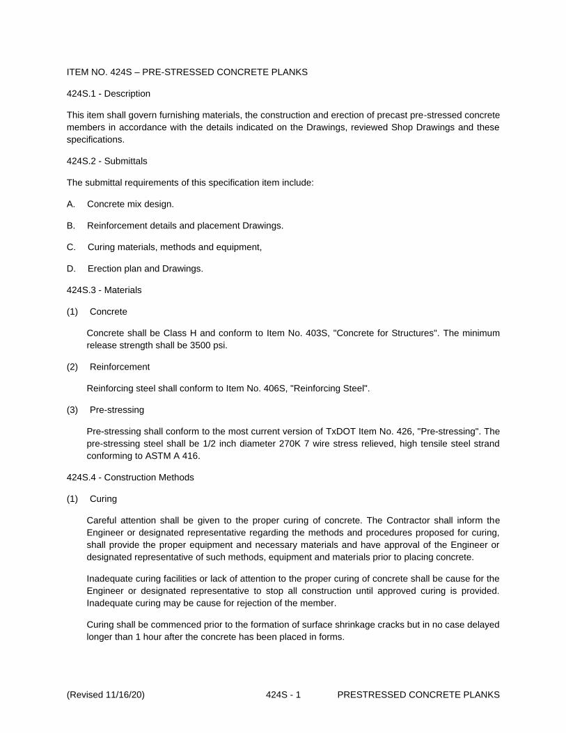
(Revised 11/16/20) 424S - 1 PRESTRESSED CONCRETE PLANKS
ITEM NO. 424S – PRE-STRESSED CONCRETE PLANKS
424S.1 - Description
This item shall govern furnishing materials, the construction and erection of precast pre-stressed concrete
members in accordance with the details indicated on the Drawings, reviewed Shop Drawings and these
specifications.
424S.2 - Submittals
The submittal requirements of this specification item include:
A. Concrete mix design.
B. Reinforcement details and placement Drawings.
C. Curing materials, methods and equipment,
D. Erection plan and Drawings.
424S.3 - Materials
(1) Concrete
Concrete shall be Class H and conform to Item No. 403S, "Concrete for Structures". The minimum
release strength shall be 3500 psi.
(2) Reinforcement
Reinforcing steel shall conform to Item No. 406S, "Reinforcing Steel".
(3) Pre-stressing
Pre-stressing shall conform to the most current version of TxDOT Item No. 426, "Pre-stressing". The
pre-stressing steel shall be 1/2 inch diameter 270K 7 wire stress relieved, high tensile steel strand
conforming to ASTM A 416.
424S.4 - Construction Methods
(1) Curing
Careful attention shall be given to the proper curing of concrete. The Contractor shall inform the
Engineer or designated representative regarding the methods and procedures proposed for curing,
shall provide the proper equipment and necessary materials and have approval of the Engineer or
designated representative of such methods, equipment and materials prior to placing concrete.
Inadequate curing facilities or lack of attention to the proper curing of concrete shall be cause for the
Engineer or designated representative to stop all construction until approved curing is provided.
Inadequate curing may be cause for rejection of the member.
Curing shall be commenced prior to the formation of surface shrinkage cracks but in no case delayed
longer than 1 hour after the concrete has been placed in forms.

(Revised 11/16/20) 424S - 2 PRESTRESSED CONCRETE PLANKS
An approved water or membrane cure, when permitted, shall be used as an interim measure prior to
elevated temperature or other methods of curing.
Concrete shall be cured continuously except as provided for form removal, until the concrete
strength as indicated by compressive test of cylinders cured with the members, has reached the
"Release Strength" or "Handling Strength" indicated. Members shall be covered to prevent rapid
drying for a period of 72 hours after release of stress or after reaching handling strength. All
members shall be protected from freezing during the above period. A period not to exceed 4 hours
will be permitted for removal to a storage area prior to resuming the balance of curing and protection
required.
A curing day is defined as a calendar day when the temperature, taken in the shade away from
artificial heat is above 50°F for at least 19 hours or for colder days, if satisfactory provisions are
made to maintain the temperature at all surfaces of the concrete above 50°F for the entire 24 hours.
All concrete shall be steam or water cured, except that membrane curing may be used as interim
curing on the top surface of concrete piling. Only Type 1 membrane curing compound will be
permitted for interim curing.
(a) Water Curing
All exposed surfaces of the concrete shall be kept wet continuously for the required curing time.
The water used for curing shall meet the requirements for concrete mixing water as specified in
Item No. 403S, "Concrete for Structures". Seawater will not be permitted. Water, which stains or
leaves an unsightly residue, shall not be used.
Water curing will be permitted as follows:
1. Wet Mat Method
For water curing by wet mat method, cotton mats, polyethylene sheeting or polyethylene
burlap blankets may be used.
The mats, sheets or blankets shall not be placed in contact with prestressed concrete
member until such time that damage will not occur to the surfaces.
The mats, sheets or blankets shall be adequately anchored and weighted to provide
continuous contact with all concrete surfaces. Any concrete surfaces, which cannot be
cured by contact, shall be enclosed by mats, adequately anchored, so that outside air
cannot enter the enclosure. Sufficient moisture shall be provided inside the enclosure to
keep all of the surfaces of the concrete wet for the required curing time.
2. Water Spray Method
For water curing by the water spray method, overlapping sprays or sprinklers shall be used
so that all concrete surfaces are kept wet continuously.
(b) Elevated Temperature Curing
Curing by elevated temperatures will be permitted as follows:
1. Steam Curing

(Revised 11/16/20) 424S - 3 PRESTRESSED CONCRETE PLANKS
(Steam curing is defined as use of steam above 85°F for curing.) When steam curing of
concrete is provided, the temperature inside the curing jacket at the surface of the concrete
shall not exceed 165°F for more than 1 hour during the entire steam-curing period.
Concrete exposed to temperatures exceeding 180°F will not be accepted.
Sufficient moisture shall be provided inside the curing jacket so that all surfaces of the
concrete are wet.
An unobstructed air space of not less than 6 inches shall be provided between all surfaces
of the concrete and the curing jacket. Steam outlets shall be positioned so that live steam
is not applied directly on the concrete, reinforcing steel or tendons.
The location of steam lines, location of control points for discharge of steam into the curing
jacket, and the number and type of openings for steam distribution within the curing jacket
shall be arranged so that temperature variation between any points in the enclosure shall
not exceed 20°F.
Steam curing shall not commence until the concrete has been in place a minimum of 3
hours.
During the application of steam, the temperature inside the curing jacket shall be raised
uniformly at a rate not to exceed 40°F per hour.
Temperature decrease at the end of the curing operation shall not exceed the same rate.
When elevated temperature curing is used, members shall remain protected until the
differential between the temperature inside the curing jacket and the outside air is not more
than 25°F.
2. Alternate Methods
Other methods of elevated temperature curing may be permitted by the Engineer or
designated representative provided temperature maximums, rate of temperature variation,
humidity control, etc. are in accordance with the requirements for steam curing. Permission
shall be obtained from the Engineer or designated representative, in writing, for use of any
alternate method.
424S.5 - Handling, Hauling and Erection
The Contractor shall be responsible for proper handling, lifting, storing, hauling and erection of all
members so that they may be placed in the structure without damage.
Unless approved on erection and/or shop drawings, pre-stressed members shall be maintained in a flat
position at all times and shall be picked up and supported near the ends of the member in such a way to
prevent torsion. Members may be lifted by other methods approved by the Engineer or designated
representative in writing.
No member shall be moved from the casting yard until all requirements for curing and strength
requirements have been attained.

(Revised 11/16/20) 424S - 4 PRESTRESSED CONCRETE PLANKS
424S.6 - Defects and Breakage
Failure of individual wires in a 7 wire strand or of wires in a parallel wire tendon is acceptable provided the
total area of wire failure is not more than 2 percent of the total cross sectional area of tendons in any
member. Failure of entire strand will be subject to structural review.
Fine hair cracks or checks on the surface of the member which, as determined by the Engineer, do not
extend to the plane of the nearest reinforcement will not be cause for rejection unless they are numerous
and extensive. Diagonal cracks, which indicate damage from torsion, will be subject to a structural review
prior to acceptance. Vertical or horizontal cracks, which are 1/16 inch or less to the concrete, are
acceptable. Cracks in excess of this are subject to review prior to acceptance.
Cracks, which extend into the plane of the reinforcing steel and/or pre-stressed tendons, but are
acceptable otherwise, shall be repaired by sealing with a latex-base adhesive, grout or with epoxy.
Small damaged or honeycombed areas, which are purely surface in nature, (not over 1 inch deep) may
be repaired. Damage or honeycomb in excess of this will be tentatively rejected but will be subject to
structural review.
424S.7 - Quality of Work
Concrete shall be placed in the forms and spaded, tamped or vibrated until thoroughly compacted and
until it entirely covers the surface and has a monolithic finish. The top surface shall be floated and
troweled to a uniform smooth surface, then finished with a camel hairbrush or wood float to a gritty
texture. The outer edges and joints shall be rounded with approved tools to the radius indicated.
424S.8 - Measurement
The work performed and the materials furnished as indicated will be measured by the square foot of top
surface area of concrete.
424S.9 - Payment
The work performed as indicated will be paid for at the unit price bid per square foot for "Pre-stressed
Concrete Planks", which price shall be full compensation for furnishing and placing all materials, including
all reinforcing steel, furnishing and tensioning Pre-stressing steel, for grouting holes and for any other
materials, manipulation, transporting, labor, tools, equipment and incidentals necessary to complete the
work.
Payment will be made under:
Pay Item No. 424-
A:
Pre-stressed Concrete Planks ____________ Inch ×
____________ Inch
Per Square
Foot.
END

(Revised 11/16/20) 430S - 1 PC CONCRETE CURB AND GUTTER
ITEM NO. 430S - PC CONCRETE CURB AND GUTTER
430S.1 - Description
This item shall govern Portland Cement (PC) concrete curb, PC concrete curb and gutter with reinforcing
steel or PC concrete laydown curb as required, that is constructed in accordance with this specification on
an approved subgrade and base in conformity with Standard Detail Series 430S and the lines, grades,
section indicated on the Drawings or as established by the Engineer or designated representative.
430S.2 - Submittals
Within 14 days prior to the commencement of related work, the Contractor shall electronically submit the
following submittal requirements:
A. Class A PC concrete mix design,
B. Type of Installation (i.e. PC Concrete Curb and Gutter or PC Concrete Curb or PC Concrete
Laydown Curb) and construction details (i.e. base, reinforcing steel, joints, curing membrane),
C. Identification of the type, source, mixture, Pure Live Seed (PLS) and rate of application of the
seeding.
430S.3 - Materials
A. Concrete
The PC concrete shall conform to Class A Concrete, Section 403S.7 (Table 4) of Standard
Specification Item No. 403S, "Concrete for Structures" or Sections 360S.4 and 360S.6 of Standard
Specification Item No. 360S, "Concrete Pavement" when curb and gutter is to be constructed integral
with the pavement.
B. Reinforcing Steel
Reinforcing steel shall conform to Standard Specification Item No. 406S, "Reinforcing Steel."
C. Expansion Joint Materials
Expansion joint materials shall conform to Standard Specification Item No. 408S, "Concrete Joint
Materials."
D. Membrane Curing Compound
Membrane curing compound shall conform to Standard Specification Item No. 409S, "Membrane
Curing."
E. Flexible Base
Aggregate shall conform to Standard Specification Item No. 210S, "Flexible Base".

(Revised 11/16/20) 430S - 2 PC CONCRETE CURB AND GUTTER
430S.4 - Construction Methods
A. Subgrade and Base Preparation
Subgrade for curb and gutter shall be excavated and prepared to depth and width requirements
indicated on the Drawings, including a minimum of 12 inches behind the curb, unless a greater width
is indicated on the Drawings. The subgrade shall be shaped to the line, grades, cross section and
dimensions indicated on the Drawings. A minimum of 4 inches (unless a greater or different base is
indicated on the Drawings) of flexible base shall be spread, wetted and thoroughly compacted under
curb and gutter as specified in Standard Specification Item No. 210S, "Flexible Base". If dry, the
base shall be sprinkled lightly with water before PC concrete is deposited thereon.
B. C & G Forms
Forms shall be of metal, well-seasoned wood or other approved material. The length of the forms
shall be a minimum of 10 feet. Flexible or curved forms shall be used for curves of 100-foot radius or
less. Wood forms for straight sections shall be not less than 2 inches in thickness. Forms shall be a
section, that is satisfactory to the Engineer or designated representative, of the depth required and
clean, straight, free from warp and, if required, oiled with a light form oil. All forms shall be securely
staked to line and grade and maintained in a true position during the placement of PC concrete.
C. Reinforcing Steel
The reinforcing steel, if required, shall be placed as shown on the typical section of the Drawings.
Care shall be exercised to keep all steel in its proper location during PC concrete placement.
D. Joints
Joints shall be of the type and spacing shown on the Drawings. Expansion joint material, 3/4 inch in
thickness, shall be provided at intervals not to exceed 40 feet and shall extend the full width and
depth of the PC concrete. Weakened plane joints shall be made 3/4 inch deep at 10-foot intervals.
All joint headers shall be braced perpendicular and at right angles to the curb.
Two round smooth dowel bars, 1/2 inch in diameter and 24 inches in length, shall be installed at
each expansion joint. 16 inches of one end of each dowel shall be thoroughly coated with hot oil,
asphalt or red lead, so that it will not bond to the concrete. The dowels shall be installed with a dowel
sleeve on the coated end as indicated on the Drawings or equivalent method as directed by the
Engineer or designated representative.
E. PC Concrete Placement and Form Removal
Concrete shall be placed in the forms and properly consolidated. Within 1 hour after PC concrete
placement, a thin coating, that is no more than 1/2 inch nor less than 1/4 inch thick of finish mortar,
composed of 1 part Portland Cement to 2 parts fine aggregate, shall be worked into the exposed
faces of the curb and gutter by means of a "mule". After the PC concrete has become sufficiently set,
the exposed edges shall be rounded by the use of an edging tool to the radii indicated on Standard
Detail 432S-1 “Sidewalk”. The entire exposed surface of the curb and gutter shall be floated to a
uniform smooth surface, and then finished with a camel hairbrush to a gritty texture. The forms shall
remain in place a minimum of 24 hours unless approved otherwise by the Engineer or designated
representative.

(Revised 11/16/20) 430S - 3 PC CONCRETE CURB AND GUTTER
After removal of the forms, any minor honeycombed surfaces shall be plastered with a mortar mix as
described above. Excessively honeycombed curb and gutter, as determined by the Engineer or
designated representative, shall be completely removed and replaced when directed.
F. Curing
Immediately after finishing the curb, concrete shall be protected by a membrane curing conforming to
Standard Specification Item No. 409S, "Membrane Curing."
After a minimum of 3 days curing and before placement of the final lift of the base course, the curb
shall be backfilled to the full height of the PC concrete, tamped and sloped as directed by the
Engineer or designated representative. The upper 4 inches of backfill shall be of clean topsoil that
conforms to Standard Specification Item No. 130S, "Borrow" and is free of stones and debris.
G. Seeding in Turf Areas
When turf is to be established, preparation of the seedbed shall conform to Item No. 604S, "Seeding
for Erosion Control".
430S.5 - Measurement
Accepted work as prescribed by this item will be measured by the lineal foot of PC concrete curb and
gutter, PC concrete curb and/or PC concrete laydown curb, complete in place.
430S.6 - Payment
The work performed as prescribed by this item will be paid for at the unit bid price per lineal foot for "PC
Concrete Curb and Gutter" or PC Concrete Curb. The price shall include full compensation for all work as
set forth and described under payment Method A and/or B.
A. Method A (Pay Item No. 430S-A)
This payment method shall include all the work performed for "PC Concrete Curb and Gutter"
complete, at the unit bid price. The unit bid price shall include full compensation for excavation,
preparation of the subgrade, furnishing and placing all concrete and base material, reinforcing steel,
dowels, expansion joint material, curing material, backfill and for all other materials, manipulations,
labor, tools, equipment and incidentals necessary to complete the work.
B. Method B (Pay Item No. 430S-B)
This payment method includes all the work performed for "PC Concrete Curb and Gutter", complete,
at the unit bid price. The unit bid price shall include full compensation for fine grading, furnishing and
placing concrete and reinforcing steel, dowels, expansion joint material, curing material, backfill and
for all other materials, manipulations, labor, tools, equipment and incidentals necessary to complete
the work.
C. Method C (Pay Item No. 430S-C)
This payment method includes all the work performed for " PC Concrete Curb" complete, at the unit
bid price. The unit bid price shall include full compensation for excavation, furnishing and placing all
concrete and base material, reinforcing steel, dowels, expansion joint material, curing material,

(Revised 11/16/20) 430S - 4 PC CONCRETE CURB AND GUTTER
backfill and for all other materials, manipulations, labor, tools, equipment and incidentals necessary
to complete the work.
D. Method D (Pay Item No. 430S-D)
This payment method includes all the work performed for "PC Concrete Curb" complete, at the unit
bid price. The unit bid price shall include full compensation for fine grading, furnishing and placing
concrete and reinforcing steel, dowels, expansion joint material, curing material, backfill and for other
materials, manipulations, labor, tools, equipment and incidentals necessary to complete the work.
E. Method E (Pay Item No. 430S-E)
This payment method shall include all the work performed for "PC Concrete Laydown Curb"
complete, at the unit bid price. The unit bid price shall include full compensation for excavation,
preparation of the subgrade, furnishing and placing all concrete and base material, reinforcing steel,
dowels, expansion joint material, curing material, backfill and for all other materials, manipulations,
labor, tools, equipment and incidentals necessary to complete the work.
F. Method F (Pay Item No. 430S-F)
This payment method includes all the work performed for "PC Concrete Laydown Curb" complete, at
the unit bid price. The unit bid price shall include full compensation for fine grading, furnishing and
placing concrete and reinforcing steel, dowels, expansion joint material, curing material, backfill and
for other materials, manipulations, labor, tools, equipment and incidentals necessary to complete the
work.
Payment will be made under one of the following:
Pay Item No. 430S-A: PC Concrete Curb and Gutter (Excavation) Per Lineal Foot.
Pay Item No. 430S-B: PC Concrete Curb and Gutter (Fine Grading) Per Lineal Foot.
Pay Item No. 430S-C: PC Concrete Curb (Excavation) Per Lineal Foot.
Pay Item No. 430S-D: PC Concrete Curb (Fine Grading) Per Lineal Foot.
Pay Item No. 430S-E: PC Concrete Laydown Curb (Excavation) Per Lineal Foot.
Pay Item No. 430S-F: PC Concrete Laydown Curb (Fine Grading) Per Lineal Foot.
END

(Revised 11/16/20) 431S - 1 MACHINE LAID PC CONCRETE CURB AND GUTTER
ITEM NO. 431S - MACHINE LAID PORTLAND CEMENT CONCRETE CURB AND GUTTER
431S.1 - Description
This item shall govern Portland cement (PC) concrete curb and gutter and reinforcing steel dowels,
constructed in accordance with this specification on an approved base in conformity with the lines,
grades, sections and Standard Detail Series 430S and indicated on the Drawings or as established by the
Engineer or designated representative.
431S.2 - Submittals
The submittal requirements of this specification item include:
A. Class I PC concrete mix design,
B. Type of Installation (i.e. PC Concrete Curb and Gutter or PC Concrete Curb) and construction details
(i.e. base, reinforcing steel, joints, curing membrane),
C. Identification of the type, source, mixture, Pure Live Seed (PLS) and rate of application of the
seeding.
431S.3 - Materials
A. PC Concrete
The PC Concrete shall conform to Class I Concrete, Section 403S.7 (Table 4) of Standard
Specification Item No. 403S, "Concrete for Structures."
B. Reinforcing Steel
Reinforcing steel shall conform to Standard Specification Item No. 406S, "Reinforcing Steel."
C. Expansion Joint Materials
Preformed expansion joint materials shall conform to Standard Specification Item No. 408S,
"Concrete Joint Materials."
D. Membrane Curing Compound
Membrane curing compound shall conform to Standard Specification Item No. 409S, "Membrane
Curing."
E. Flexible Base
Flexible base material shall conform to Standard Specification Item No. 210S, "Flexible Base."
F. Stabilized Base
A stabilized base identified as a Type A or B shall conform to the requirements of Standard
Specification Item 340S, "Hot Mix Asphaltic Concrete Pavement."
431S.4 - Construction Methods
A. Subgrade and Base Preparation
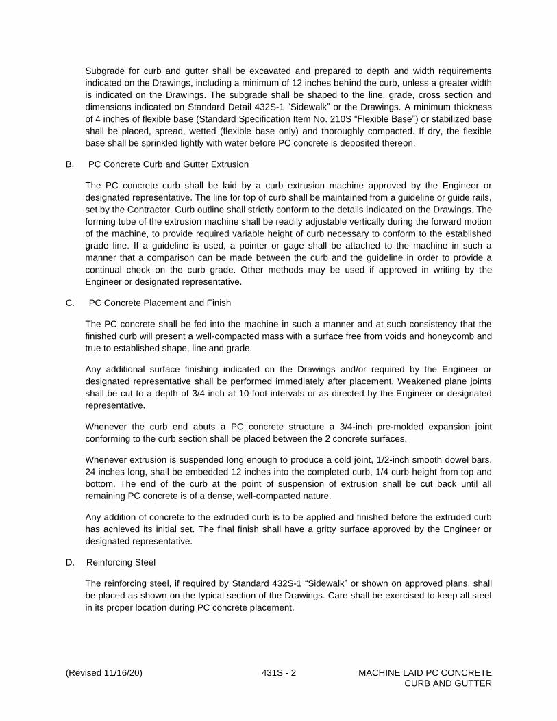
(Revised 11/16/20) 431S - 2 MACHINE LAID PC CONCRETE CURB AND GUTTER
Subgrade for curb and gutter shall be excavated and prepared to depth and width requirements
indicated on the Drawings, including a minimum of 12 inches behind the curb, unless a greater width
is indicated on the Drawings. The subgrade shall be shaped to the line, grade, cross section and
dimensions indicated on Standard Detail 432S-1 “Sidewalk” or the Drawings. A minimum thickness
of 4 inches of flexible base (Standard Specification Item No. 210S “Flexible Base”) or stabilized base
shall be placed, spread, wetted (flexible base only) and thoroughly compacted. If dry, the flexible
base shall be sprinkled lightly with water before PC concrete is deposited thereon.
B. PC Concrete Curb and Gutter Extrusion
The PC concrete curb shall be laid by a curb extrusion machine approved by the Engineer or
designated representative. The line for top of curb shall be maintained from a guideline or guide rails,
set by the Contractor. Curb outline shall strictly conform to the details indicated on the Drawings. The
forming tube of the extrusion machine shall be readily adjustable vertically during the forward motion
of the machine, to provide required variable height of curb necessary to conform to the established
grade line. If a guideline is used, a pointer or gage shall be attached to the machine in such a
manner that a comparison can be made between the curb and the guideline in order to provide a
continual check on the curb grade. Other methods may be used if approved in writing by the
Engineer or designated representative.
C. PC Concrete Placement and Finish
The PC concrete shall be fed into the machine in such a manner and at such consistency that the
finished curb will present a well-compacted mass with a surface free from voids and honeycomb and
true to established shape, line and grade.
Any additional surface finishing indicated on the Drawings and/or required by the Engineer or
designated representative shall be performed immediately after placement. Weakened plane joints
shall be cut to a depth of 3/4 inch at 10-foot intervals or as directed by the Engineer or designated
representative.
Whenever the curb end abuts a PC concrete structure a 3/4-inch pre-molded expansion joint
conforming to the curb section shall be placed between the 2 concrete surfaces.
Whenever extrusion is suspended long enough to produce a cold joint, 1/2-inch smooth dowel bars,
24 inches long, shall be embedded 12 inches into the completed curb, 1/4 curb height from top and
bottom. The end of the curb at the point of suspension of extrusion shall be cut back until all
remaining PC concrete is of a dense, well-compacted nature.
Any addition of concrete to the extruded curb is to be applied and finished before the extruded curb
has achieved its initial set. The final finish shall have a gritty surface approved by the Engineer or
designated representative.
D. Reinforcing Steel
The reinforcing steel, if required by Standard 432S-1 “Sidewalk” or shown on approved plans, shall
be placed as shown on the typical section of the Drawings. Care shall be exercised to keep all steel
in its proper location during PC concrete placement.

(Revised 11/16/20) 431S - 3 MACHINE LAID PC CONCRETE CURB AND GUTTER
E. Joints
Joints shall be of the type and spacing shown on the Drawings. Expansion joint material, 3/4 inch in
thickness, shall be provided at intervals not to exceed 40 feet and shall extend the full width and
depth of the PC concrete. Weakened plane joints shall be made 3/4 inch deep at 10-foot intervals.
All joint headers shall be braced perpendicular and at right angles to the curb.
Two round smooth dowel bars, 1/2 inch in diameter and 24 inches in length, shall be installed at
each expansion joint. Sixteen inches of one end of each dowel shall be thoroughly coated with hot
oil, asphalt or red lead, so that it will not bond to the concrete. The dowels shall be installed with a
dowel sleeve on the coated end as indicated on the Drawings or equivalent method as directed by
the Engineer or designated representative.
F. Curing
When finishing operations are completed the curb shall be cured conforming to Standard
Specification Item No. 409S, "Membrane Curing."
When the curb has cured a minimum of 3 days and prior to placement of the final lift of base course,
it shall be backfilled to the full height of the PC concrete, tamped and sloped to drain as directed by
the Engineer or designated representative.
In turf areas, the upper 4 inches of backfill shall be of clean topsoil, that conforms to Standard
Specification Item No. 130S, "Borrow" and shall be free of stones and debris.
G. Seeding in Turf Areas
When turf is to be established, the preparation of the seedbed shall conform to Standard
Specification Item No. 604S, "Seeding for Erosion Control".
431S.5 - Measurement
Machine Laid PC Concrete Curbs will be measured by the lineal foot of completed and accepted curb,
complete in place.
431S.6 - Payment
The work performed as prescribed by this item will be paid for at the unit bid price per lineal foot for
"Machine Laid PC Concrete Curb and Gutter". The unit bid price shall include full compensation for all
work as set forth and described under payment Method A, B or C below.
A. Method A: With Excavation (Pay Item No. 431S-A)
This payment method includes all the work performed for "Machine Laid PC Concrete Curb and
Gutter", complete, at the unit bid price. The unit bid price shall include full compensation for
excavation, preparation of the subgrade, furnishing and placing all base material, reinforcing steel,
dowels, expansion joint materials, curing material, backfill and all other materials, manipulations,
labor, tools, equipment and incidentals necessary to complete the work.
B. Method B: With Fine Grading (Pay Item No. 431S-B)
This payment method includes all the work performed for "Machine Laid PC Concrete Curb and
Gutter", complete, at the unit bid price. The unit bid price shall include full compensation for fine

(Revised 11/16/20) 431S - 4 MACHINE LAID PC CONCRETE CURB AND GUTTER
grading, furnishing and placing reinforcing steel, dowels, expansion joint material, curing material,
backfill and for all other materials, manipulations, labor, tools, equipment and incidentals necessary
to complete the work.
C. Method C: Included in the unit price bid for this specification Incidental Work (Pay Item No. 431S-C)
This method includes all the work performed as incidental work relating to "Machine Laid PC
Concrete Curb and Gutter" as may be detailed and noted on the Drawings or included and described
in the "Special Provisions" of the Standard Contract Documents.
Payment will be made under one of the following:
Pay Item No. 431S-A: Machine Laid Curb and Gutter (Excavation) Per Lineal Foot.
Pay Item No. 431S-B: Machine Laid Curb and Gutter (Fine Grading) Per Lineal Foot.
Pay Item No. 431S-C: Machine Laid Curb and Gutter (Incidental Work) Per Lineal Foot.
END
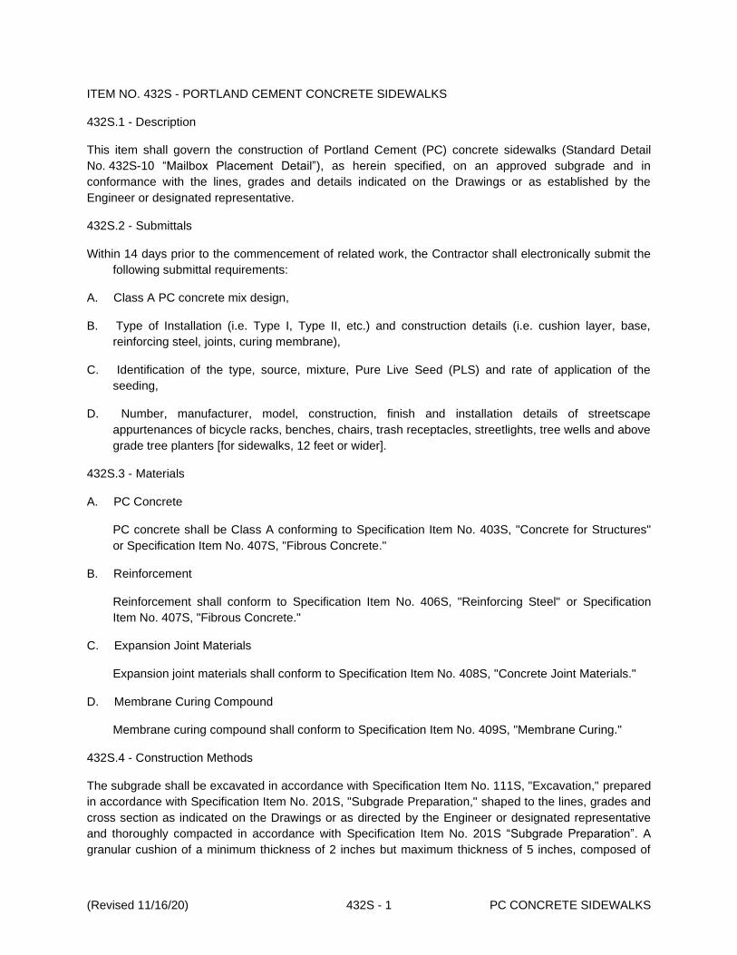
(Revised 11/16/20) 432S - 1 PC CONCRETE SIDEWALKS
ITEM NO. 432S - PORTLAND CEMENT CONCRETE SIDEWALKS
432S.1 - Description
This item shall govern the construction of Portland Cement (PC) concrete sidewalks (Standard Detail
No. 432S-10 “Mailbox Placement Detail”), as herein specified, on an approved subgrade and in
conformance with the lines, grades and details indicated on the Drawings or as established by the
Engineer or designated representative.
432S.2 - Submittals
Within 14 days prior to the commencement of related work, the Contractor shall electronically submit the
following submittal requirements:
A. Class A PC concrete mix design,
B. Type of Installation (i.e. Type I, Type II, etc.) and construction details (i.e. cushion layer, base,
reinforcing steel, joints, curing membrane),
C. Identification of the type, source, mixture, Pure Live Seed (PLS) and rate of application of the
seeding,
D. Number, manufacturer, model, construction, finish and installation details of streetscape
appurtenances of bicycle racks, benches, chairs, trash receptacles, streetlights, tree wells and above
grade tree planters [for sidewalks, 12 feet or wider].
432S.3 - Materials
A. PC Concrete
PC concrete shall be Class A conforming to Specification Item No. 403S, "Concrete for Structures"
or Specification Item No. 407S, "Fibrous Concrete."
B. Reinforcement
Reinforcement shall conform to Specification Item No. 406S, "Reinforcing Steel" or Specification
Item No. 407S, "Fibrous Concrete."
C. Expansion Joint Materials
Expansion joint materials shall conform to Specification Item No. 408S, "Concrete Joint Materials."
D. Membrane Curing Compound
Membrane curing compound shall conform to Specification Item No. 409S, "Membrane Curing."
432S.4 - Construction Methods
The subgrade shall be excavated in accordance with Specification Item No. 111S, "Excavation," prepared
in accordance with Specification Item No. 201S, "Subgrade Preparation," shaped to the lines, grades and
cross section as indicated on the Drawings or as directed by the Engineer or designated representative
and thoroughly compacted in accordance with Specification Item No. 201S “Subgrade Preparation”. A
granular cushion of a minimum thickness of 2 inches but maximum thickness of 5 inches, composed of

(Revised 11/16/20) 432S - 2 PC CONCRETE SIDEWALKS
crusher screenings, gravel and sand, crushed rock or coarse sand, shall be spread, wetted thoroughly,
tamped and leveled. The granular cushion shall be moist at the time the PC concrete is placed.
If the subgrade is undercut by more than 4 inches or the elevation of the natural ground is more than 4
inches below "top of subgrade," then a necessary backfill/embankment layer of an approved material
shall be placed and compacted with a mechanical tamper. Hand tamping will not be permitted.
Where the subgrade is rock or gravel, 70% of which is rock; the 2-inch cushion need not be used. The
Engineer or designated representative will determine if the subgrade meets the above requirements.
Sidewalk forms shall be constructed of metal or well-seasoned wood not less than 2 inches in thickness,
with a section satisfactory to the Engineer or designated representative. The forms shall be clean,
straight, and free from warp with a depth equal to the thickness of the finished work. All forms shall be
securely staked to line and grade and maintained in a true position during the deposition of PC concrete.
Before PC concrete is placed, the forms shall be thoroughly oiled with a light form oil.
Expansion joint material ¾-inch thick, shall be provided where the new construction abuts an existing
structure, sidewalk or driveway. Similar expansion material shall be placed around all obstructions
protruding through the sidewalk. The expansion joint material shall be placed vertically and shall extend
the full depth of the PC concrete. Maximum spacing of expansion joints shall be 40 feet as indicated on
the Drawings or as directed by the Engineer or designated representative. Weakened plane joints shall
be spaced at 5 feet on center. Normal dimensions of the weakened plane joints shall be 1/4 inch wide
and 3/4 inch deep. All joints shall be constructed perpendicular (90 degrees) to the centerline of walk and
shall match any previously placed concrete joints. For sidewalks with widths exceeding 6 feet longitudinal
weakened-plane tooled joints shall be provided as indicated on the Drawings or as directed by the
Engineer or designated representative.
Reinforcement for sidewalks shall consist either of polypropylene fibrillated fibers (only when approved by
the City Engineer) or 6″ × 6″ × W1.4 × W1.4 welded wire fabric or one layer #3 (10M) reinforcing bars,
placed no more than 18 inches on center both directions. All reinforcement shall be accurately placed at
slab mid-depth, equidistant from the top and bottom of the PC concrete and held firmly in place by means
of bar supports of adequate strength and number that will prevent displacement and keep the steel at its
proper position during the placement of the PC concrete. In no instance shall the steel be placed
directly on the subgrade or sand cushion layer.
Prior to placement of the concrete, the reinforcement installation shall be inspected by the Engineer or
designated representative to ensure conformance with the drawings, specifications and this item. In
addition, care shall be exercised to keep all steel in its proper position during placement of the PC
concrete. If during placement of the concrete, the reinforcement is observed to lose bar support, float
upward or move in any direction, the placement shall be stopped until corrective action is taken.
Splices in wire fabric shall overlap sufficiently to allow two pairs of transverse wires to be tied together
and no splice of less than 6 inches will be permitted. Splices in the #3 (10M) bars shall have a minimum
lap of 12 inches.
Where driveways cross sidewalks, additional reinforcing shall be placed in the sidewalk as indicated on
the Drawings.
PC concrete sidewalk ramps shall be formed to produce a finished surface with detectable warnings
(Standard Detail 432S-2A “Detectable Warning Paver”) in accordance with the requirements of the
American Disabilities Act and Texas Accessibility Standards (TAS), including Sections 4.29.2 and

(Revised 11/16/20) 432S - 3 PC CONCRETE SIDEWALKS
A4.29.2. The PC concrete sidewalk ramps shall be constructed in accordance with appropriate City of
Pflugerville Standard Details (Standard Details 432S-3 “Type 1 Curb Ramps-Full Intersection”, 432S-3A
“Type 1 Curb Ramps- T Intersection” through 432S-3H “Type 1 Ramps Within PC/PT of Curb and Gutter”,
432S-5 “Type 1 Sidewalk Curb Ramp”, 432S-5A “Type 1 Sidewalk Curb Ramp With Left Flare”, 432S-5B
Type 1B Sidewalk Curb Ramp”, etc.).
Detectable warning for the ramps shall consist of raised truncated domes with a diameter of nominal
0.9 inch, a height of nominal 0.2 inch and center-to-center spacing of nominal 2.35 inches and shall
contrast visually with adjoining surfaces, either light on dark or dark-on-light. The material used to provide
contrast shall be an integral part of the walking surface.
When indicated on the Drawings or as directed by the Engineer or designated representative, the
construction of the sidewalk ramp shall include the installation of interlocking concrete paving units
(Standard Specification Item No. 480S, "Concrete Paver Units for Sidewalks and Streetscape
Requirements"). The concrete paving units shall be constructed in accordance with Standard
Specification Item No. 485S, "Concrete Paving Units for Sidewalk Ramps" and appropriate City of
Pflugerville Standard Details (Standard Details 432S-2A “Detectable Warning Paver”, 432S-3 “Type 1
Curb Ramps-Full Intersection”, 432S-3A “Type 1 Curb Ramps- T Intersection” through 432S-3H “Type 1
Ramps Within PC/PT of Curb and Gutter”, 432S-5 “Type 1 Sidewalk Curb Ramp”, 432S-5A “Type 1
Sidewalk Curb Ramp With Left Flare” and 432S-5B Type 1B Sidewalk Curb Ramp”,
At the proper time after finishing, the surface shall be protected by a membrane, compound curing agent
or by wetted cotton or burlap mats, conforming to Item No. 409S, "Membrane Curing." The sides of the
PC concrete shall be cured in the forms. If the forms are removed during the curing process, the curing
shall be continued by the placement of fill against the exposed concrete edges or by other procedures
conforming to Item No. 410S, "Concrete Structures." The top 4 inches of fill shall be clean topsoil
conforming to Item No. 604S, "Seeding for Erosion Control."
Existing sidewalk that is scheduled for removal and replacement shall be removed and the underlying
material shaped to the lines, grades and cross section as indicated in the drawings or as directed by the
Engineer or designated representative. The removal and/or relocation of obstructions, including but not
limited to signs, trash cans and benches on concrete pads, abandoned manholes, sprinkler control valves
and landscaping, shall be performed, as indicated on the drawings, in a manner acceptable to the
Engineer or designated representative. Removal and/or relocation of obstructions will be considered
incidental work to this item and will not be paid for directly.
Existing PVC pipe drains in and behind curb shall be removed and replaced as required in new sidewalk
and/or curb and gutter. In areas of proposed sidewalk construction, where curb and gutter is to remain in
place, existing PVC pipe shall be cut far enough behind the back of curb to allow sufficient room for joint
fittings to connect to new or salvaged PVC pipe.
The Contractor shall be responsible for removing and replacing mailboxes that are located in the
construction area, while assuring that mail delivery will not be interrupted as a result of the construction
activities. Mailboxes shall not be laid on the ground.
All necessary excavation, filling and grading of the slopes adjacent to the completed concrete sidewalks
will be considered incidental work pertaining to this item and will not be paid for directly. The adjacent
excavation and grading of the slopes shall be done in a manner acceptable to the Engineer or designated
representative.
432S.5 - Streetscape Furniture Installation Requirements

(Revised 11/16/20) 432S - 4 PC CONCRETE SIDEWALKS
A. General
Bicycle racks, benches and chairs, trash receptacles, tree wells and above grade tree wells and
planters shall only be installed in sidewalks that are 12 feet or wider. When installation is indicated
on the Drawings or directed by the Engineer or designated representative, these items shall be
permanently installed as indicated in; 432S-7A “New Trees Planted within Sidewalk 12’ or Greater –
Clay Soils” and 432S-7F “Tree Well Without Grate”. Above grade tree wells shall be installed in
conformance with Standard Detail 432S-7E “Tree Well With Seat”, while above grade tree planters
shall be installed in conformance with Standard Detail Nos. 432S-7D “Above Grade Tree Planters.”
B. Location Requirements
1. Benches.
Benches shall be placed either perpendicular to the curb with the center of the bench on line
with trees and light poles and facing toward the building entry, or parallel to the building and
within 6″ (150 mm) of the building wall, facing out to the street.
2. Bike Racks.
Bike racks are to be placed perpendicular to the curb with the centerline of the rack on line with
trees and light poles.
3. Trash Receptacles.
Trash receptacles shall either be placed along the curb, with the center line of the receptacle on
line with the trees and light poles, or shall be located at the building entry in alignment with the
structural bay system of the building. If located at the entry there shall be no more than 1 foot
clearance between the receptacle and the building wall.
432S.6 - Pedestrian Railing
When a pedestrian railing installation is required along sidewalks for pedestrian protection as indicated on
the Drawings or directed by the Engineer or designated representative, this type of pedestrian railing shall
be permanently installed in conformance with one of the following designated Standard Details: 707S-1
“Pedestrian Rail”, 707S-2 “Pedestrian ADA Handrail Option 1”, 707S-3 “Pedestrian ADA Handrail on
Curb-Option 2” or 707S-4 “Pedestrian ADA Handrail on Sidewalk Option 3”.
When a pedestrian railing installation is required along portions of sidewalks identified as 'ramps' for ADA
accessibility purposes as indicated on the Drawings or directed by the Engineer or designated
representative, this type of pedestrian railing shall be permanently installed in conformance with one of
the following designated Standard Details: 707S-2 “Pedestrian ADA Handrail Option 1”, 707S-3
“Pedestrian ADA Handrail on Curb-Option 2” or 707S-4 “Pedestrian ADA Handrail on Sidewalk Option 3”.
432S.7 - Measurement
Accepted work performed as prescribed by this item will be measured by the square foot of surface area
of "Concrete Sidewalk."
Accepted work performed as prescribed by "Sidewalk Ramps" will be measured per each for the type of
ramp indicated on the Drawings.

(Revised 11/16/20) 432S - 5 PC CONCRETE SIDEWALKS
Accepted work performed as prescribed by "Streetscape Appurtenances" will be measured per each for
the type of appurtenance indicated on the drawings.
Accepted work performed as prescribed by "Pedestrian Railing" will be measured per lineal foot of the
type of railing indicated on the Drawings.
432S.8 - Payment
The work performed as prescribed by this item for concrete sidewalk will be paid for at the unit bid price
per square foot for "Concrete Sidewalk" and/or "Sidewalks Reconstruction"; per each for "Concrete
Sidewalk Ramps" and "Streetscape Appurtenances" or per lineal foot for "Pedestrian Railing".
The unit bid price for new sidewalk shall include full compensation for excavating and/or removal and/or
relocating obstructions, vegetating adjacent areas disturbed by sidewalk construction, preparing the
subgrade; for furnishing and placing all materials including cushion material, all reinforcement, bar
supports, joints, expansion joint materials, and for any other materials, manipulations, labor, tools,
equipment, finishing, curing and incidentals necessary to complete the work.
The unit bid price for sidewalk reconstruction shall include full compensation for excavating and/or
removal of existing sidewalk and other obstructions, relocating obstructions, replacing PVC drain pipe, re-
vegetating adjacent areas disturbed by sidewalk construction, preparing the subgrade; for furnishing and
placing all materials including cushion material, all reinforcement, bar supports, joints, expansion joint
materials, and for any other materials, manipulations, labor, tools, equipment, finishing, curing and
incidentals necessary to complete the work.
The unit bid price for ramps shall include full compensation for preparing the subgrade when not included
as a separate item; for furnishing and placing all materials, manipulation, labor, tools, equipment and
incidentals necessary to complete the work. All necessary excavation, filling and grading of the slopes
adjacent to the completed concrete paver units will be included in the unit price bid for the item of
construction in which this item is used, unless included as a separate pay item in the Contract bid form.
The unit bid price for streetscape appurtenances shall include full compensation for the individual item
(i.e. bench, chair, bicycle rack, trash receptacle, street light or above grade tree planter), as well as the
removal of existing sidewalk, preparation of footings, furnishing and placing all materials, manipulation
and finishing, labor, tools, equipment and incidentals necessary to complete the work.
The unit bid price for pedestrian railing shall include full compensation for the complete installation of the
specific pedestrian railing including but not limited to preparation of footings or curb, furnishing and
placing all materials, manipulation and finishing, labor, tools, equipment and incidentals necessary to
complete the work.
Payment will be made under one of the following:
New Sidewalks
Pay Item 432S-A: New PC Concrete Sidewalks, (Thickness ____) Per Square
Foot.
Sidewalks Reconstruction
Pay Item 432S-R: Reconstruct Concrete Sidewalks to _____ thickness,
including removal of existing sidewalk
Per Square
Foot.

(Revised 11/16/20) 432S - 6 PC CONCRETE SIDEWALKS
Ramps
Pay Item 432S-RP-1: PC Sidewalk Curb Ramp with Pavers (Type I) Per Each.
Pay Item 432S-RP-1A: PC Sidewalk Curb Ramp with Pavers (Type IA) Per Each.
Pay Item 432S-RP-1B: PC Sidewalk Curb Ramp with Pavers (Type IB) Per Each.
Streetscape Appurtenances
Pay Item 432S-SAC-1: Streetscape Bench ( ____________ inches in length) Per Each.
Pay Item 432S-SAC-2: Streetscape Chair Per Each.
Pay Item 432S-SAC-3: Streetscape Bicycle Rack Per Each.
Pay Item 432S-SAC-4: Streetscape Trash Receptacle Per Each.
Pay Item 432S-SAC-5: Streetscape Street Light Per Each.
Pay Item 432S-SAC-7C: Streetscape Tree Well for Concrete Sidewalks Per Each.
Pay Item 432S-SAC-7D: Streetscape Above Grade Tree Planters Per Each.
Pay Item 432S-SAC-7E: Streetscape Tree Well with Seat Per Each.
Pay Item 432S-SAC-7F: Streetscape Tree Well without Grate Per Each.
Pay Item 432S-SAC-7G: Streetscape Above Grade Galvanized Steel Tree
Planters
Per Each.
Pesdestrian Railing
Pay Item 432S-PRC-1: Pedestrian Railing (Standard 707S-1) Per LF.
Pay Item 432S-PRC-2: Pedestrian ADA Railing - Option 1 (Standard 707S-2) Per LF.
Pay Item 432S-PRC-3: Pedestrian ADA Railing - Option 2 (Standard 707S-3) Per LF.
Pay Item 432S-PRC-4: Pedestrian ADA Railing - Option 3 (Standard 707S-4) Per LF.
END

(Revised 11/16/20) 433S - 1 PC CONCRETE DRIVEWAYS
ITEM NO. 433S - PC CONCRETE DRIVEWAYS
433S.1 - Description
This item shall govern construction of Portland Cement (PC) concrete driveways, as herein specified, on
an approved subgrade, in conformity with the lines, grades and cross section indicated on the Drawings,
identified in Standard Detail Series 433S, or as established by the Engineer or designated representative.
433S.2 - Submittals
Within 14 days prior to the commencement of related work, the Contractor shall electronically submit the
following submittal requirements:
A. Class A and/or Item 360S “Concrete Pavement”,
B. Type of Installation (i.e. Type I, Flared Type I, Type II, etc.) and construction details (i.e. cushion
layer, base, reinforcing steel, joints, curing membrane),
C. Identification of the type, source, mixture, Pure Live Seed (PLS) and rate of application of the
seeding.
433S.3 - Materials
A. Concrete
The PC Concrete for a Type I driveway (Standards 433S-1 and 433S-1A) shall conform to Class A,
Section 403S.7 (Table 4) of Standard Specification Item No. 403S, "Concrete for Structures." The
PC Concrete for a Type II driveway (Standard 433S-2 “Type II Driveway”) shall conform to a normal
concrete mix design for concrete pavement, Section 360S.5(A) of Standard Specification Item No.
360S, "Concrete Pavement".
B. Reinforcing Steel
Reinforcing steel and welded wire fabric shall conform to Standard Specification Item No. 406S,
"Reinforcing Steel".
C. Expansion Joint Materials
Expansion joint materials shall conform to Standard Specification Item No. 408S, "Concrete Joint
Materials."
D. Membrane Curing Compound
Membrane curing compound shall conform to Standard Specification Item No. 409S, "Membrane
Curing."
E. Cushion Layer
The Cushion layer shall consist of crusher screenings, gravel or coarse sand.
433S.4 - Construction Methods
All forms and forming, placement of reinforcement, placement of concrete, form removal, finishing and
curing shall conform to Standard Specification Item No. 410S, "Concrete Structures".

(Revised 11/16/20) 433S - 2 PC CONCRETE DRIVEWAYS
A. Subgrade Preparation
The subgrade shall be excavated, prepared and shaped to the lines, grades and cross sections
indicated on the Drawings or as directed by the Engineer or designated representative. The
subgrade shall be thoroughly compacted in accordance with Standard Specification Item No. 201S,
"Subgrade Preparation". A 2-inch minimum compacted thickness cushion shall be spread, wetted
thoroughly, tamped and leveled. The cushion shall be moist at the time the PC concrete is placed.
If the subgrade is undercut or natural ground is located below the top of subgrade, the necessary
backfill material shall conform to Standard Specification Item 130S, "Borrow" and shall be compacted
with a mechanical tamper. Hand tamping will not be permitted.
Where the subgrade material consists of gravel or includes 70 percent of rock, the 2-inch cushion
layer may not be required. The Engineer or designated representative will determine if the subgrade
meets the above requirements.
B. Forms
Forms shall be of metal, well-seasoned wood or other approved material of a section satisfactory to
the Engineer or designated representative. Wood forms shall not be less than 2 inches nominal
thickness for straight runs and 1-inch nominal thickness for curved runs. Forms shall be a section
satisfactory to the Engineer or designated representative and clean, straight, free from warp and of a
depth equal to the thickness of the finished work.
All forms shall be securely staked to line and grade and maintained in a true position during the
placement of PC concrete.
C. Joints
Joints shall be of the type and spacing shown on the Drawings. Expansion joint material, 3/4 inch
thick, shall be provided where the new construction abuts the existing sidewalks or driveways or as
directed by the Engineer or designated representative. The expansion joint material shall be placed
vertically and shall extend the full depth of the PC concrete. Similar expansion material shall be
placed around all obstructions protruding through the driveway. Weakened plane joints shall be
located on 10-foot centers or as directed by the Engineer or designated representative. Normal
dimensions of the weakened plane groove joints shall be 1/4-inch wide and 3/4-inch deep.
D. Reinforcement
Reinforcement for Type I driveways shall consist of 1 layer of 6 x 6 by W 1.4 x W 1.4 wire fabric or
No. 3 bars placed not more than 18 inches on center, both directions. Reinforcement for Type II
driveways shall consist of 1 layer of No. 4 bars placed no more than 18 inches on center, both
directions.
All reinforcements shall be accurately placed equidistant from the top and bottom of the PC concrete
slab and held firmly in place by means of bar supports of adequate strength and number that will
prevent displacement and keep the steel at its proper position. In no instance shall the steel be
placed directly on the subgrade or sand cushion layer.
Prior to placement of the concrete, the reinforcement installation shall be inspected by the Engineer
or designated representative to ensure conformance with the drawings, specifications and this item.
In addition, care shall be exercised to keep all steel in its proper position during the placement of PC

(Revised 11/16/20) 433S - 3 PC CONCRETE DRIVEWAYS
concrete. If during placement of the concrete, the reinforcement is observed to lose bar support, float
upward or move in any direction, the placement shall be stopped until corrective action is taken.
Splices in wire fabric shall overlap sufficiently to allow two pairs of transverse wires to be tied
together and no splice of less than 6 inches will be permitted. Splices in the No. 3 and No. 4 bars
shall have a minimum lap of 12 inches.
E. PC Concrete Placement and Finishing
The PC concrete shall be placed in the forms and spaced, tamped and thoroughly compacted until it
entirely covers the surface and has a monolithic finish. The top surface shall be floated and troweled
to a uniform smooth surface, then finished with a broom or wood float to a gritty texture unless
otherwise indicated on the Drawings. The outer edges and joints shall be rounded with approved
tools to a 1/4-inch radius. Care shall be exercised to prevent loss of dummy joints or rounded edges
when applying the broom finish.
F. Curing
At the proper time after finishing, the surface shall be protected by a membrane compound curing
agent in conformance with Standard Specification Item No. 409S, "Membrane Curing" or by wetting
cotton or burlap mats. Either method shall be subject to approval by the Engineer or designated
representative.
Traffic shall be barricaded from using the driveway for a minimum of 4 days after initial placing and
may be opened to traffic only with approval of the Engineer or designated representative.
G. Incidental Work
All necessary excavation, filling and grading of the slopes, adjacent to the completed PCC.
driveways, will be considered incidental work pertaining to this item and will not be paid for directly.
The adjacent excavation and grading of the slopes shall be done with topsoil conforming to Standard
Specification Item No. 130S, "Borrow". When turf is to be established, the preparation of the
seedbed shall conform to Standard Specification Item No. 604S, "Seeding for Erosion Control", in a
manner acceptable to the Engineer or designated representative.
433S.5 - Measurement
Accepted work performed as prescribed by this item will be measured by the square foot of surface area
of the specific type of PC concrete driveway.
433S.6 - Payment
The work performed as prescribed by this item will be paid for at the unit bid price per square foot for
"Concrete Driveways." The unit bid price shall include full compensation for preparation of the subgrade;
furnishing and placing all materials, including cushion layer, all reinforcing steel, bar supports and
expansion joint materials; and any other materials, manipulations, labor, tools, equipment and incidentals
necessary to complete the work.

(Revised 11/16/20) 433S - 4 PC CONCRETE DRIVEWAYS
Payment will be made under:
Pay Item No. 433S-A: Type I PC Concrete Driveway Per Square Foot.
Pay Item No. 433S-B: Flared Type I PC Concrete Driveway Per Square Foot.
Pay Item No. 433S-C: Type II PC Concrete Driveway Per Square Foot.
END

(Revised 11/16/20) 434S - 1 PC CONCRETE MEDIANS AND ISLANDS
ITEM NO. 434S - PC CONCRETE MEDIANS AND ISLANDS
434S.1 - Description
This item shall govern construction of Portland Cement (PC) concrete traffic islands and medians in
accordance with these specifications and in conformity to the lines, grades, sections and details indicated
on the Drawings or as established by the Engineer or designated representative.
434S.2 - Submittals
The submittal requirements of this specification item include:
A. Class A PC concrete mix design,
B. Type of Installation (i.e. Median or Island) and construction details (i.e. cushion layer, base,
reinforcing steel, joints, curing membrane).
434S.3 - Materials
A. PC Concrete
The PC concrete shall conform to Class A Concrete, Section 403S.7 (Table 4) of Standard
Specification Item No. 403S, "Concrete for Structures".
B. Reinforcing Steel
Reinforcing steel and welded wire fabric shall conform to Standard Specification Item No. 406S,
"Reinforcing Steel".
C. Expansion Joint Materials
Preformed expansion joint materials shall conform to Standard Specification Item No. 408S,
"Concrete Joint Materials".
D. Membrane Curing Compound
Membrane curing compound shall conform to Standard Specification Item No. 409S, "Membrane
Curing".
E. Admixtures
Admixtures shall conform to Standard Specification Item No. 405S, "Concrete Admixtures".
F. Aggregate Cushion
Cushion layer shall consist of crusher screening, gravel, sand, crushed stone or "Flexible Base"
materials (Standard Specification Item No. 210S “Flexible Base”) approved by the Engineer or
designated representative.
434S.4 - Construction Methods
All forms and forming, placement of reinforcement, placement of concrete, form removal, finishing and
curing shall conform to Standard Specification Item No. 410S, "Concrete Structures".

(Revised 11/16/20) 434S - 2 PC CONCRETE MEDIANS AND ISLANDS
A. PC Concrete Mix Design
The PC concrete shall conform to an approved design mix for a Class A PC concrete on file with the
City or proposed Class A mix designs with the necessary test data may be submitted for approval by
the Engineer or designated representative.
High range water reducing admixtures conforming to Standard Specification Item No. 360, "Concrete
Pavement" may be used when approved by the Engineer or designated representative.
B. Subgrade and Base Preparation
The subgrade shall be excavated, prepared and shaped to the lines, grades and cross section
indicated on the Drawings or as directed by the Engineer or designated representative, and shall be
thoroughly compacted conforming to Standard Specification Item No. 201S, "Subgrade Preparation".
A cushion layer, 2 inches minimum thickness, shall be spread, wetted thoroughly, tamped and
leveled. The cushion shall be moist at the time the PC concrete is placed.
C. Forms
Forms shall be of metal, well-seasoned wood or other approved material. The length of the forms
shall be a minimum of 10 feet. Flexible or curved forms shall be used for curves of 100-foot radius or
less. Wood forms for straight sections shall be not less than 2 inches in thickness. Forms shall be a
section, that is satisfactory to the Engineer or designated representative, and shall be clean, free
from warp, and of a depth equal to the finished work. All forms shall be securely staked to line and
grade and maintained in a true position during the placement of the PC concrete and, if required,
forms shall be thoroughly oiled with a light form oil prior to PC concrete placement. If the adjacent
existing asphalt pavement is damaged during construction, it shall be restored to its original
condition.
D. Reinforcement
Reinforcement shall conform to the details indicated on the Drawings or the directions of the
Engineer or designated representative. All reinforcement shall be accurately placed at slab mid-
depth, equidistant from the top and bottom of the PC concrete, and held firmly in place by means of
bar supports of adequate strength and number that will prevent displacement and keep the
reinforcement in its proper position during the placement of the PC concrete. In no instance shall the
steel be placed directly on the subgrade or sand cushion layer.
Prior to placement of the concrete, the reinforcement installation shall be inspected by the Engineer
or designated representative to ensure conformance with the drawings, specifications and this item.
In addition, care shall be exercised to keep all steel in its proper position during placement of the PC
concrete. If during placement of the concrete, the reinforcement is observed to loose bar support,
float upward or move in any direction, the placement shall be stopped until corrective action is taken.
E. Joints
Joints shall be of the type and spacing shown on the Drawings. Expansion joint material, 3/4 inch in
thickness, shall be placed as indicated on the Drawings with a maximum spacing of 40 feet or as
directed by the Engineer or designated representative. Expansion joints shall be placed on the same
alignment when adjacent to a PC concrete pavement. Weakened plane joints shall be made 3/4 inch

(Revised 11/16/20) 434S - 3 PC CONCRETE MEDIANS AND ISLANDS
deep and equally spaced, normally at 5 foot on centers or as directed by the Engineer or designated
representative. Expansion joints shall be required between the curb and median PC concrete.
F. PC Concrete Placement and Finishing
The PC concrete shall be placed in the forms to the depth indicated on the Drawings, and properly
consolidated and until mortar entirely covers the surface and forms a monolithic finish. If a vibrator is
used, care shall be taken not to leave it in one location long enough to induce segregation. The top
surface shall be floated and troweled to a uniform smooth surface, then finished with a camel
hairbrush or wood float to a gritty texture. The outer edges shall be rounded with approved tools to
the radii indicated on the Drawings.
When the ambient air temperature is above 85°F, an approved retarding agent will be required in all
PC concrete. The maximum temperature of all PC concrete placed shall not exceed 95°F, unless
High Range Water Reducer Admixtures are used.
G. Curing
Immediately after finishing the PC concrete median or island, the PC concrete surface shall be
protected by a membrane-compound curing agent conforming to Standard Specification Item No.
409S, "Membrane Curing". The curing procedures shall be acceptable to the Engineer or designated
representative.
434S.5 - Measurement
Accepted work as prescribed by this item will be measured by the square foot of surface area of PC
concrete medians and/or PC concrete island, complete in place.
434S.6 - Payment
The work performed as prescribed by this item will be paid for at the unit bid price per square foot for "PC
Concrete Medians and Islands." The unit bid price shall include full compensation for preparation of the
subgrade; finishing and placing all materials, including all reinforcing steel, welded wire fabric; bar
supports and any other materials, manipulation, labor, tools, equipment and incidentals necessary to
complete the work.
Payment will be made under:
Pay Item No. 434S-A: ____________ Inch PC Concrete Medians and Islands Per Square Foot.
END

(Revised 11/16/20) 435S - 1 PC CONCRETE STEPS
ITEM NO. 435S - PC CONCRETE STEPS
435S.1 - Description
This item shall govern construction of Portland Cement (PC) concrete steps (with or without reinforcing
steel as required) on approved subgrade and in conformity with the lines, grades, sections and details
indicated on the Drawings or as established by the Engineer or designated representative.
435S.2 - Submittals
The submittal requirements of this specification item include:
A. Class A PC concrete mix design,
B. Construction details (i.e., reinforcing steel, curing membrane, etc.)
435S.3 - Materials
A. Concrete
The PC concrete shall be Class A Concrete, Section 403S.7 (Table 4) of Standard Specification Item
No. 403S, "Concrete for Structures".
B. Reinforcing Steel
Reinforcing steel shall conform to Standard Specification Item No. 406S, "Reinforcing Steel".
C. Expansion Joint Materials
Expansion joint materials shall conform to Standard Specification Item No. 408S, "Concrete Joint
Materials".
D. Membrane Curing Compound
Membrane curing compound shall conform to Standard Specification Item No. 409S, "Membrane
Curing".
435S.4 - Construction Methods
All excavation, including removal of existing steps or sidewalks and backfill, shall conform to Standard
Specification Item No. 401S, "Structural Excavation and Backfill".
All forms and forming, placement of reinforcement when required, placement of concrete, form removal,
finishing and curing shall conform to Standard Specification Item No. 410, "Concrete Structures".
The height of the steps will be determined by the existing grade or as directed by the Engineer or
designated representative. The tread width is normally 10 inches and the riser is normally 7 ½ inches, but
these dimensions may be varied to fit existing conditions as directed by the Engineer or designated
representative. Step width will match the existing sidewalk, but not less than 3 feet.
Reinforcement for the steps, when required, shall be as indicated on the Drawings.
Expansion joints shall be placed along the lower and upper tread and along each side when abutting PC
concrete.

(Revised 11/16/20) 435S - 2 PC CONCRETE STEPS
The steps shall be constructed monolithically. The PC concrete shall be placed in the forms and properly
consolidated until it covers the area. The top surface shall be floated and troweled to a smooth surface,
then finished with a camel hairbrush or wood float to a gritty texture and neat appearance. The outer
edges and joints shall be rounded with approved tools with a 1/4-inch radius.
At the proper time after finishing, the surface shall be protected by a membrane compound curing agent
conforming to Standard Specification Item No. 409S, "Membrane Curing" or by wetting cotton or burlap
mats. Either method shall be subject to approval by the Engineer or designated representative.
435S.5 - Measurement
Accepted work as prescribed by this item will be measured by the cumulative width in feet of individual
steps (treads) including the bottom step.
435S.6 - Payment
The work performed as prescribed by this item will be paid for at the unit bid price per lineal foot for "PC
Concrete Steps". The unit bid price shall include full compensation for all excavation, forms, concrete,
reinforcement, curing, backfill, sloping; all labor, tools, materials, equipment; and incidentals necessary to
complete the work.
Payment will be made under:
Pay Item No. 435S-A: PC Concrete Steps Per Lineal Foot.
END

(Revised 11/16/20) 436S - 1 PC CONCRETE VALLEY GUTTERS
ITEM NO. 436S - PC CONCRETE VALLEY GUTTERS
436S.1 - Description
This item shall govern the construction of Portland Cement (PC) concrete valley gutters on an approved
subgrade in conformity to the lines, grades, Standard Detail No. 436S-2 “Concrete Valley Gutter” and
details indicated on the Drawings or as established by the Engineer or designated representative.
436S.2 - Submittals
The submittal requirements of this specification item include:
A. Class A PC concrete mix design,
B. Construction details (i.e., reinforcing steel, curing membrane, etc.).
436S.3 - Materials
A. PC Concrete
The Portland cement concrete shall be Class A Concrete, Section 403.7 (Table 4) of Standard
Specification Item No. 403, "Concrete for Structures".
B. Reinforcing Steel
Reinforcing steel and welded wire fabric shall conform to Standard Specification Item No. 406S,
"Reinforcing Steel".
C. Expansion Joint Materials
Expansion joint materials shall conform to Standard Specification Item No. 408S, "Concrete Joint
Materials".
D. Membrane Curing Compound
Membrane curing compound shall conform to Standard Specification Item No. 409S, "Membrane
Curing".
436S.4 - Construction Methods
All forms and forming, placement of reinforcement, placement of concrete, form removal, finishing and
curing shall conform to Standard Specification Item No. 410S, "Concrete Structures".
A. Subgrade Preparation
Where a stabilized subbase is not provided, the subgrade shall be excavated in accordance with
Standard Specification Item No. 111S, "Excavation" to remove all unstable or otherwise
objectionable material and all holes, ruts and depressions shall be filled with approved material.
Rolling shall be performed in accordance with Standard Specification Item No. 230S “Rolling (Flat
Wheel)” or 232S “Rolling (Pneumatic Tire)”, to the extent indicated on the Drawings or directed by
the Engineer or designated representative. The roadbed shall be completed to the plane of the
typical sections indicated on the Drawings and the lines and/or grades established by the Engineer

(Revised 11/16/20) 436S - 2 PC CONCRETE VALLEY GUTTERS
or designated representative. All work shall conform to Standard Specification Item No. 201S,
"Subgrade Preparation".
If the subgrade is dry, the valley gutter area shall be sprinkled lightly immediately before the PC
concrete is placed.
Unless otherwise specified on the Drawings, all necessary excavation, filling and grading of the
subgrade will be considered incidental work pertaining to this item and will not be paid for directly.
B. Forms
Forms shall be of metal, well-seasoned wood or other approved material. Wood forms for straight
sections shall be not less than 2 inches nominal thickness. Forms shall be a section satisfactory to
the Engineer or designated representative and clean, straight, free from warp and of a depth equal to
the thickness of the finished work. All forms shall be securely staked to line and grade and
maintained in a true position during the placement of concrete and, if necessary, forms shall be oiled
with a light form oil, prior to placement of PC concrete.
C. Reinforcing Steel
Reinforcement for PC concrete valley gutters shall conform to Standard Detail No. 436S-2 “Concrete
Valley Gutter”; details indicated on the Drawings or as directed by the Engineer or designated
representative. Care shall be exercised to keep the reinforcement in its proper position during the
placement of PC concrete.
D. Joints
Joints shall be of the type and spacing shown on the Drawings. Expansion joint material 3/4 inch
thick shall be provided as indicated on the Drawings or as directed by the Engineer or designated
representative. The expansion joint material shall be placed vertically and shall extend the full depth
of the PC concrete. Weakened plane joints shall be provided on 10-foot centers or as directed by the
Engineer or designated representative. Normal dimensions of the weakened plane joints shall be 1/4
inch wide and 3/4 inch deep.
E. Placement and Finishing
The PC concrete shall be placed in the forms and properly consolidated until it entirely covers the
surface and has a monolithic finish. The top surface shall be screeded and floated to a uniform
smooth surface, then finished with a wood float to a gritty texture. The outer edges shall be rounded
with approved tools to a 1/4-inch radius.
F. Curing
At the proper time after finishing, the surface shall be protected by a membrane-curing compound
conforming to Standard Specification Item No. 409S, "Membrane Curing" or by wetting cotton or
burlap mats. Either method shall be subject to approval by the Engineer or designated
representative. Traffic shall be securely barricaded from using the PC concrete valley gutter for a
minimum of 4 days after initial placement and may be opened to traffic only with the approval of the
Engineer or designated representative.
436S.5 - Measurement

(Revised 11/16/20) 436S - 3 PC CONCRETE VALLEY GUTTERS
Accepted work performed as prescribed by this item will be measured by the square foot of surface area
of PC concrete placed. The square foot measurement shall include the reinforced monolithic curb placed
at the ends of the valley gutter.
436S.6 - Payment
The work performed as prescribed by this item will be paid for at the unit bid price per square foot for "PC
Concrete Valley Gutters". The unit bid price shall include full compensation for preparation the subgrade;
furnishing and placing all materials, including reinforcing steel and expansion joint materials; any other
materials, manipulations, labor, tools, equipment, barricading and all incidentals necessary to complete
the work.
Payment will be made under:
Pay Item No. 436S-A: PC Concrete Valley Gutters Per Square Foot.
END

(Revised 11/16/20) 438S - 1 ELASTOMERIC MATERIALS
ITEM NO. 438S - ELASTOMERIC MATERIALS
438S.1 - Description
This item shall govern the materials, testing, fabrication and placement of elastomeric materials, except
as otherwise covered in other specifications or on the Drawings.
438S.2 - Submittals
The submittal requirements of this specification item include:
A. Type and Manufacturer of proposed products.
B. Certification that proposed products meet the requirements of this section.
438S.3 - Materials
(1) Elastomeric Bearings
When specified on the Drawings, structural members shall be seated on elastomeric bearings.
These bearings may be either "plain" (consisting of elastomer only) or "laminated" (consisting of
alternating individual layers of elastomer and nonelastic laminates) as indicated. Elastomeric
bearings shall be specified on the Drawings by hardness (durometer), size and configuration and, in
the case of laminated bearings, by the thickness of the individual layers of elastomer and the size
and position of special connection members, if any, required to be vulcanized with the bearing.
(a) General
Unless otherwise indicated, the elastomer for bearings shall be formulated from previously
unvulcanized 100 percent virgin polychloroprene or 100 percent virgin polyisoprene rubber
polymers. Rubber-like polymers employed in the elastomer formulation shall be exclusively of
the polychloroprene or natural polyisoprene type. Bearings will not be acceptable if the
elastomer employed contains previously vulcanized rubber (natural of synthetic) or other
synthetic rubber-like polymers.
Nonelastic laminates shall be 1/16 inch [-0 inch, + 1/16 inch] thick steel strip or sheet. Metal for
special connections shall conform to ASTM A 36, unless otherwise shown on the plans.
(b) Physical Properties of the Elastomer
Elastomer formulated from polychloroprene shall meet the requirements shown in Table A.
Elastomer formulated from polyisoprene shall meet the requirements of Table B. Material tests
shall be made in accordance with the test methods stipulated except that all tests shall be made
on the finished product and standard laboratory test slabs will not be utilized for this purpose.
The values shown in Tables A and pertain to performed on samples taken from the finished
product.
The apparatus employed in preparing test specimens from the finished product shall be in
accordance with ASTM Designation: D 3183, "Standard Practice for Rubber-Preparation of
Pieces for Test Purposes from Products".

(Revised 11/16/20) 438S - 2 ELASTOMERIC MATERIALS
Compression set test specimens shall be taken from the finished product. In bearing
thicknesses exceeding 1/2 inch or elastomer layers in laminated bearings exceeding 1/2 inch,
the full thickness of the bearing of elastomer layer shall be utilized. The 25 percent compression
shall be employed and obtained through the utilization of appropriate thickness of space bar
and/or shims.
Beveled or wedge shaped bearings of elastomer layers in laminated bearings shall have the
compression set specimens selected from sections of the bearings or layers which have been
properly cut or ground so that the top and bottom surfaces of the circular compression set
specimens will have essentially parallel surfaces. The maximum permissible thickness of such
bearings or layers, after rendering the upper and lower surfaces parallel, will be used as a
source for the cutting of the cylindrical test specimens employed in the compression set test in
accordance with ASTM D 395, "Standard Test Methods for Rubber Property-Compression
Test", as modified herein.
(c) Formulation Prequalification and Certification
All bearings furnished by the Contractor shall be produced by a bearing manufacturer who has
previously submitted the required prequalification test samples and certification and whose
elastomer formulation has been initially approved for use by the Engineer or designated
representative. Each elastomer formulation produced by a manufacturer must be approved by
the Engineer or designated representative prior to its first use on Department projects. To
prequalify and obtain initial approval of a particular formulation, the bearing manufacturer shall
submit to the Engineer or designated representative, well in advance of anticipated use of the
manufacturer's product, certified test results of actual test values obtained when the physical
properties of the elastomer to be furnished were tested for compliance with the pertinent
specifications.
The bearings manufacturer shall certify that all of the samples submitted are of the same basic
elastomer formulation and of equivalent cure to that used in the finished products to be
furnished on City projects.
The Producer may be required to perform the complete prequalification testing procedure again
during later production should the Engineer or designated representative require such retesting.
(d) Manufacturing Requirements
All components of a "laminated" bearing shall be molded together to form an integral unit free of
voids or separations in the elastomer or between the elastomer and the nonelastic laminates or
special connections unless specifically required or permitted by the plans or these
specifications. The elastomer between laminates or special connections and on the outer
surfaces of the bearing shall be well vulcanized, uniform and integral such that it is incapable of
being separated by any mechanical means into separate, definite, well-defined elastometric
layers. Evidence of this layered construction, either at the outer surfaces or within the bearing,
shall be cause for rejection of such laminated bearing shipments.
All edges of nonelastic laminates shall be covered by a minimum of 1/8 inch of elastomer,
except that exposure of the laminates will be permitted at approved laminate restraining devices
and around holes that will be entirely enclosed in the finished structure. Unless otherwise
indicated, all laminates shall be parallel with the bottom surface of the bearing, subject to the
tolerances that follow.

(Revised 11/16/20) 438S - 3 ELASTOMERIC MATERIALS
Plain bearings may be molded individually, cut from previously molded strips or slabs, molded
to the full thickness of the finished bearings or extruded and cut to length. The finished bearings
shall have no voids or separations detectable either at the bearing surfaces or within the
bearing unless specifically required or permitted by the Drawings or these specifications. Plain
elastomeric bearings shall be well vulcanized, uniform and integral units of construction such
that the bearing is incapable of being separated by any mechanical means into separate,
definite and well-defined elastomeric layers.
Evidence of layered construction, either at the outer surfaces or within the bearing, shall be
cause for rejection of such bearing shipments.
TABLE A
Interpolate Between Values Shown for Other Hardness Values
Hardness 50 60 70 80 90
ORIGINAL PHYSICAL PROPERTIES
Hardness ASTM D 2240, Type A Durometer
Tensile Strength, Minimum psi
ASTM D 412
Elongation at Break, minimum percent
50+5
2250
450
60+5
2250
360
70+5
2250
270
80+5
1800
135
90+5
1800
90
ACCELERATED TESTS TO DETERMINE LONG TERM
AGING CHARACTERISTICS, OVEN AGED 70 HR at
212°F ASTM D 573;
Hardness points change, maximum 0 to +15 0 to +15 0 to +15 0 to +15 0 to +15
Tensile Strength, % change maximum -15 -15 -15 -15 -15
Elongation at Break, % change maximum 40 40 40 40 40
OZONE: 100 PPHM IN AIR BY VOLUME; 20% STRAIN
AT 100 +2°F
— ASTM D 1149*, 100 hours
No
Cracks
No
Cracks
No
Cracks
No
Cracks
No
Cracks
COMPRESSION SET-22 HRS AT 158°F
ASTM D 395(Method B)**, % Maximum
25 25 25 25 25
LOW TEMPERATURE RESISTANCE ASTM D 746
PROCEDURE B, Brittleness at -14.8°F
No
Failure
No
Failure
No
Failure
No
Failure
No
Failure
ADHESION (PREQUALIFICATION ONLY)
For laminated bearings, bond between the elastomer and laminates will be qualitatively evaluated by the
procedure outlined in the TxDOT Manual of Testing Procedures, Test Method Tex-601-J.
* Samples to be solvent wiped before test to remove traces of surface impurities.
** Modified in that test is performed on specimens of essentially full bearing or layer thickness with the

(Revised 11/16/20) 438S - 4 ELASTOMERIC MATERIALS
25 percent compression obtained through the use of appropriate spacer bars and/or shims.
TABLE B
Interpolate Between Values Shown for Other Hardness Values
Hardness 50 60 70 80 90
ORIGINAL PHYSICAL PROPERTIES
Hardness ASTM D 2240, Type A Durometer 50+5 6-+5 70+5 80+5 90+5
Tensile Strength, Minimum psi 2250 2250 2250 1800 1800
ASTM D 412
Elongation at Break, minimum percent 405 360 270 135 90
ACCELERATED TESTS TO DETERMINE LONG TERM
AGING CHARACTERISTICS, OVEN AGED 70 HR at
212°F ASTM D 573;
Hardness points change, maximum 0 to +10 0 to +10 0 to +10 0 to +10 0 to +10
Tensile Strength, % change maximum -25 -25 -25 -25 -25
Elongation at Break, % change maximum -25 -25 -25 -25 -25
OZONE: 25 PPHM IN AIR BY VOLUME; 20% STRAIN
AT 100 +2°F— ASTM D 1149*, 48 hours
No
Cracks
No
Cracks
No
Cracks
No
Cracks
No
Cracks
COMPRESSION SET-22 HRS AT 158°F ASTM D
395(Method B)**, % Maximum 25 25 25 25 25
LOW TEMPERATURE RESISTANCE ASTM D 746
PROCEDURE B, Brittleness at -14.8°F
No
Failure
No
Failure
No
Failure
No
Failure
No
Failure
ADHESION (PREQUALIFICATION ONLY)
For laminated bearings, bond between the elastomer and laminates will be qualitatively evaluated by the
procedure outlined in the TxDOT Manual of Testing Procedures, Test Method Tex-601-J.
* Samples to be solvent wiped before test to remove traces of surface impurities.
** Modified in that test is performed on specimens of essentially full bearing or layer thickness with the

(Revised 11/16/20) 438S - 5 ELASTOMERIC MATERIALS
25 percent compression obtained through the use of appropriate spacer bars and/or shims.
The finish of cut surfaces shall be ANSI Number 250 or smoother. The batch or lot number and
the dimensions or piece mark shall be marked on each bearing and they shall remain legible
until placement in the structure.
(e) Appearance and Dimensions
Flash tolerance, finish and appearance shall meet the requirements of the latest edition of the
Rubber Handbook as published by the Rubber Manufacturers Association, Inc.; MA-F3-T.063
for molded bearings and RMA-F2 for extruded bearings.
For both plain and laminated bearings, the permissible variation from the dimensions and
configuration required by the plans and these specifications shall be as follows:
1. Overall Vertical Dimensions:
Average Total Thickness 1 ¼ inch or less: -0, + 1/8 inch
Average Total Thickness Over 1 ¼ inch: -0, +1/4 inch
2. Overall Horizontal Dimensions: -0, +1/4 inch
3. Thickness of Individual Layers of Elastomer (Laminated Bearings Only): + 1/8 inch
4. Variation from a Plane Parallel to the Theoretical Surface:
Top: 1/8 inch
Sides: 1/4 inch
Individual Nonelastic Laminates: 1/8 inch
(As determined by measurements at the edges of the bearing)
5. Position of Exposed Connection Member: 1/8 inch
6. Edge Cover of Embedded Laminates or Connection members: 0, + 1/8 inch
7. Size of Holes, Slots or Inserts: 0, + 1/8 inch
8. Position of Holes, Slots or Inserts: 0, + 1/8 inch
9. Thickness of Nonelastic Laminates: 0, + 1/16 inch
(f) Routine Inspection, Sampling and Testing
After prequalification approval, the inspection, sampling and testing of actual bearing production
will be as outlined below:
Plain Bearings

(Revised 11/16/20) 438S - 6 ELASTOMERIC MATERIALS
A minimum of one plain bearing will be taken by a representative of the Engineer from
each project or from each batch or lot in case the same batch or lot is used for more than
one project.
Routine tests for compliance with the requirements of Table A or Table B, whichever is
applicable, will be performed by the Engineer or designated representative. Samples will
not be returned.
Laminated Bearings
Each laminated bearing shall be subjected, by the manufacturer, to an average
compression of 1,000 psi or to lower average compression if so indicated in the plans or
approved by the Engineer or designated representative. This compression test will be
performed in the presence of a representative of the Engineer or designated representative
who will perform visual inspections and accept or reject the bearings at that time. The
performance of each bearing will be considered satisfactory, provided there is no visible
evidence of bond failure or other damage to the bearing because of this loading and
provided the finished bearing meets all other pertinent portions of this specification.
Samples of laminated bearings may be taken if the quality of the plant production becomes
questionable. If samples are taken, they shall be taken and tested as outlined for plain
bearings.
The manufacturer shall furnish certified laboratory test results on the elastomer properties
of each batch or lot of compound used in the manufacture of bearings, both plain and
laminated.
(2) Waterstops
Waterstops shall be furnished and installed in accordance with the details indicated. Except where
otherwise indicated on the plans, waterstops may be manufactured from either natural (plain) or
synthetic rubber or from polyvinyl chloride (PVC) as specified below:
(a) Materials
1. Natural (plain) rubber waterstops shall be manufactured from a stock composed of a high-
grade compound made exclusively from new plantation rubber, reinforcing carbon black,
zinc oxide, accelerators, antioxidants and softeners. This compound shall contain not less
than 72 percent by volume of new plantation rubber.
2. Synthetic rubber waterstops shall be manufactured from a compound made exclusively
from neoprene or GRS, reinforcing carbon black, zinc oxide, polymerization agents and
softeners. This compound shall contain not less than 70 percent by volume of neoprene or
GRS.
3. Physical properties of natural or synthetic rubbers for waterstops shall be as shown in
Table C below:

(Revised 11/16/20) 438S - 7 ELASTOMERIC MATERIALS
TABLE C: Physical Properties for Rubber for Waterstops
Natural
(Plain)
Rubber
Synthetic
(Neoprene GRS)
Rubber
Original Physical Properties:
Hardness-ASTM D 2240 (Durometer) 60 + 05 55 + 5
Tensile Strength, Minimum psi ASTM D 412 3500 2500
Elongation at Break, Minimum percent 550 425
Accelerated Tests to Determine Long-term Aging Characteristics: either-
after 7 days in air at 158° (+2°) F (ASTM D 573) or - after 48 hours in
oxygen (ASTM D 572) at 158° (+2°)F and 300 psi pressure
Tensile Strength, %change, Maximum 35 35
Elongation, % change, Maximum 35 —
4. Polyvinyl Chloride (PVC). Unless otherwise specified on the plans, the material shall
conform to the U.S. Army Corps of Engineers Specification Number, CRD-C-572-74.
"Polyvinylchloride Waterstop".
(b) Manufacturer's Certification
The manufacturer shall furnish certified test results indicating compliance with this specification
for each batch or lot of waterstop furnished under this contract. In case of doubt of the quality
furnished, the burden of proof shall be on the manufacturer and the decision of the Engineer or
designated representative shall be final.
(c) Manufacturer's Requirements
1. Rubber Waterstops
Waterstops shall be manufactured with an integral cross section which shall be uniform
within + 1/8 inch in width and the web thickness or bulb diameter, within + 1/16 and - 1/32
inch. No splices will be permitted in straight strips. Strips and special connection pieces
shall be well cured so that any cross sections shall be dense, homogeneous and free from
all porosity. All junctions in the special connection pieces shall be full-molded. During the
vulcanizing period, the joint shall be securely held by suitable clamps.

(Revised 11/16/20) 438S - 8 ELASTOMERIC MATERIALS
2. PVC Waterstops
Requirements shall be as in 1 above for rubber waterstops, except that splicing of PVC
shall be done by heat sealing the adjacent surfaces in accordance with the manufacturer's
recommendations. A thermostatically controlled electric source of heat shall be used to
make all splices. The heat shall be sufficient to melt but not to char the plastic.
3. Elastomeric Pads
When so specified on the plans, rail posts, rail members, metal shoes or minor structural
members shall be insulated, leveled, shimmed or otherwise protected by elastomeric pads,
sheets or washers.
Such bearings may be any elastomeric material, plain, fibered or laminated, having a
hardness (durometer) between 70 and 100 as certified by the manufacturer to the
Engineer.
Acceptance testing will not be required.
4. Other Elastomeric Products
Other elastomeric products shall be in accordance with the requirements on the plans.
438S.4 - Construction Methods
Elastomeric Bearings
Unless otherwise indicated, concrete bearing seats shall be float finished to the required elevation.
Variation from a level plane shall not exceed 1/16 inch within the limits of the bearing.
After erection of members on steel structures only, the horizontal distortion of the bearings shall be
measured, corrected for temperature and adjusted if necessary, so that the horizontal displacement
between top and bottom of bearings at 70° F does not exceed 15 percent of the elastomer thickness.
Welding in the vicinity of the bearings shall be done with care to avoid injury to the elastomer.
Waterstops
Waterstops shall be installed as indicated, to prohibit the flow of liquid through a joint in the concrete.
Field splices shall be either vulcanized, mechanical, using stainless steel parts or made with a rubber
splicing union of the same stock as the waterstop, at the option of the Contractor. All finished splices shall
have a tensile strength not less than 50 percent of the unspliced material.
438S.5 - Measurement
Elastomeric bearings or waterstops used with concrete units will not be measured for payment but will be
included in the unit price bid for the item of construction in which these activities are used.
END

(Revised 11/16/20) 439S - 1 PARKING LOT BUMPER CURBS
ITEM NO. 439S - PARKING LOT BUMPER CURBS
439S.1 - Description
This item shall govern parking lot bumper curbs, composed of precast concrete and reinforcing steel for
placement on gravel, asphalt and concrete surfaces as indicated on the Drawings.
439S.2 - Submittals
The submittal requirements of this specification item include:
A. Type A Portland Cement (PC) concrete design mix.
B. Reinforcing steel details.
439S.3 - Materials
A. Concrete. All precast concrete shall be Class A Concrete conforming to Specification Item No. 403S,
"Concrete for Structures".
B. Reinforcing Steel. All reinforcing steel shall be #3 bar conforming to Specification Item No. 406S,
"Reinforcing Steel."
439S.4 - Construction Methods
All forms and forming, placement of reinforcement, placement of concrete, form removal, finishing and
curing shall conform to Specification Item No. 410S, "Concrete Structures".
Reinforcement shall conform to the details indicated on the Drawings. Care shall be exercised to keep
reinforcement in its proper position during the depositing of concrete.
Concrete shall be placed in the forms to the depth indicated and vibrated until thoroughly compacted.
Care shall be taken during vibration to ensure that a vibrator is not held too long at one location that
segregation is produced. The top surface of the concrete shall be floated and troweled to a uniform
smooth surface, and then finished with a camel hairbrush or wood float to a gritty texture. The outer
edges shall be rounded with approved tools to the radii shown on the Drawings.
When the ambient air temperature is above 85°F, an approved retarding agent will be required in all
concrete unless moist curing procedures are employed. The maximum temperature of all concrete placed
shall not exceed 95°F.
439S.5 - Measurement
Parking Lot Bumper Curbs shall be measured per each, complete and in place.
439S.6 - Payment
The work performed as prescribed by this Specification Item will be paid for at the unit bid price per each.
The unit bid price shall include full compensation for: all materials, including all reinforcing steel, placing
and the concrete curb, and all labor, tools, equipment and incidentals necessary to complete the work.
Payment will be made under:

(Revised 11/16/20) 439S - 2 PARKING LOT BUMPER CURBS
Pay Item No. 439S-A: Parking Lot Bumper Curbs Per Each.
END

(Revised 11/16/20) 470S - 1 CURB CUTS FOR SIDEWALK RAMPS AND DRIVEWAYS
ITEM NO. 470S - CURB CUTS FOR SIDEWALK RAMPS AND DRIVEWAYS
470S.1 - Description
This item shall govern horizontal and vertical curb saw cuts, which are undertaken on existing or newly
placed Portland Cement (PC) concrete curb, in order to accommodate the construction of new concrete
sidewalk ramps and/or driveways at the locations indicated on the Drawings or as directed by the
Engineer or designated representative. The curb cutting operation shall be conducted from the street side
of the existing or newly placed curb.
470S.2 - Submittals
The submittal requirements of this specification item include:
A. Manufacturer and model number of saw to be used for curb cuts.
B. Documentation that the saw that is to be used on the project is designated specifically to curb cuts.
470S.3 - Materials
A diamond-blade-cutting saw shall be utilized for all required curb sawing/cutting. The saw shall be
capable of cutting existing or newly placed curb material into the shape of a ramp and/or driveway;
leaving a smooth, accurate top face. The saw shall be specifically designed for this purpose and shall be
approved by the Engineer or designated representative prior to the start of any curb cut work.
A diamond-grinding wheel shall be used for rounding the sawed concrete edges.
470S.4 - Construction Methods
The curb shall be sawn in accordance with City of Pflugerville Standard Detail 470S-1 “Curb Cut for Ramp
or Driveway” or as directed by the Engineer or designated representative. The sawing shall be made
along neat lines and shall result in smooth edges and top faces. The length of curb face, which must be
removed in order to conform to the proposed sidewalk ramp or driveway, shall be sawn full depth at the
bottom of the curb face using a diamond saw blade.
The saw cutting of the curb face shall be initiated at an elevation 1/2 inch above the existing gutter and
extended at an angle of 3/4 inch per foot upwards and away from the gutter pan to conform with the new
sidewalk ramp or driveway grade. End cuts shall be sawn full depth on an angle so that the saw cut face
provides a dimension of 55 to 60 inches for ADA ramps and 30 inches for driveways (Standard Detail
470S-1 “Curb Cut for Ramp or Driveway”). The corners of the tops of the end cuts shall be ground using a
diamond-grinding wheel to a radius of 1/4 inch.
Special care shall be taken to ensure that there is no disturbance or damage to the existing roadway
pavement, sidewalk pavement or curbs scheduled to remain. Any damage to remaining pavements,
sidewalks and/or curb due to the Contractor's operations shall be repaired at the Contractor's sole cost
and expense.
The work under this specification item shall also include the disposal of all concrete curb materials
removed during the curb cutting operation. Disposal shall conform to the requirements of City of
Pflugerville Standard Specification Item No. 401S, "Structural Excavation and Backfill."
470S.5 - Measurement

(Revised 11/16/20) 470S - 2 CURB CUTS FOR SIDEWALK RAMPS AND DRIVEWAYS
Accepted work as prescribed by this item shall not be measured for payment but will be subsidiary to the
ramp or driveway being constructed.
END