Embed Size (px)
Citation preview
02200 - 1 of 14 Kansas City, Missouri March 25, 2016 Water Services Department
SECTION 02200 EXCAVATION AND BACKFILL PART 1 GENERAL 1.1 Section Description
A. This section describes the procedures and soil material to be used with excavation, trenching, embedment, and backfill for water main construction.
1.2 Section Includes
A. Granular Fills B. Embedment C. Backfill D. Filter Fabric E. Groundwater Barrier Material F. Topsoil G. Fills and Embankment Material
1.3 Related Sections
A. Section 01016 – Water Mains Near Sewers B. Section 01300 – Submittals C. Section 01600 – Materials and Equipment D. Section 02575 – Surface Restoration E. Section 02273 – Riprap F. Section 02930 – Seeding G. Section 02931 - Sodding
1.4 References
A. ASTM C33 - Standard Specifications for Concrete Aggregates B. ASTM D698 - Test Method for Laboratory Compaction Characteristics of Soil Using -
Standard Effort (12,400 ft-lb./ft)
02200 - 2 of 14 Kansas City, Missouri March 25, 2016 Water Services Department
C. ASTM D1557 - Test Methods for Laboratory Compaction Characteristics of Soil Using - Modified Effort (56,000 ft-lb./ft)
D. ASTM D3776 - Standard Test Methods for Mass Per Unit Area (Weight) of Fabric E. ASTM D4253 - Standard Test Methods for Maximum Index Density and Unit Weight
of Soils Using a Vibratory Table F. ASTM D4254 - Standard Test Method for Minimum Index Density and Unit Weight of
Soils and Calculation of Relative Density
G. ASTM D4632 - Standard Test Method for Grab Breaking Load and Elongation of Geotextiles
1.5 Submittals
A. Follow the procedures for submittals provided in Section 01300 - Submittals. B. Submit gradation test reports and quarry quality control reports for the following
materials:
1. Granular Fill 2. Granular Embedment 3. Graded Gravel Backfill
C. Submit a Filter Fabric Manufacturer’s Data listing the average values of the
properties specified herein.
1.6 Quality Assurance
A. In accordance with OSHA “Safety and Health Regulations for Construction”, Chapter XVII of Title 29, CFR, Part 1926, the Contractor shall employ a competent person and, when necessary, a registered professional engineer, to act upon all pertinent matters of the work of this section.
B. Backfilling and construction of fills and embankments during freezing weather shall
not be done except by permission of the CITY. No backfill, fill, or embankment materials shall be installed on frozen surfaces, nor shall frozen materials, snow, or ice be placed in any backfill, fill, or embankment.
1.7 Delivery, Storage, and Handling
A. Follow the procedures for the delivery, storage, protection and handling products to and at site provided in Section 01600 - Material and Equipment.
B. Store and secure materials in neat stockpiles in locations that do not inconvenience
public and CITY operations.
C. Comply with manufacturers recommendations for storage.
02200 - 3 of 14 Kansas City, Missouri March 25, 2016 Water Services Department
PART 2 PRODUCTS 2.1 Materials
A. Granular Fills:
A. Granular Fill material shall be clean crushed rock or gravel; free from dust, clay, and trash; and graded 1-1/2 inch to No. 4 as defined in ASTM C33.
B. Embedment:
1. Granular Embedment: Granular embedment shall be clean crushed rock with
not less than 95% passing a 1/2” screen and not more than 5% passing a #4 screen.
2. Hand Placed Embedment: Hand-placed embedment shall be finely divided
job excavated material free from debris, organic material, and stones. Granular embedment material may be substituted for all or part of this type of embedment.
3. Embedment material shall not contain cinders, clay lumps, or other materials
that may cause pipe corrosion.
C. Backfill:
1. Compacted Backfill: At the option of the Contractor, compacted backfill may be suitable job excavated material or graded gravel, as described below:
a. Job Excavated Material: Job excavated material may be used for
compacted backfill when the job excavated material is finely divided and free from debris, organic material, cinders, any corrosive material, and stones larger than 3 inches in greatest dimension. Masses of moist, stiff clay shall not be used.
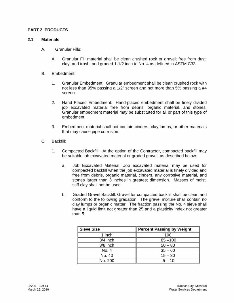
b. Graded Gravel Backfill: Gravel for compacted backfill shall be clean and
conform to the following gradation. The gravel mixture shall contain no clay lumps or organic matter. The fraction passing the No. 4 sieve shall have a liquid limit not greater than 25 and a plasticity index not greater than 5.
Sieve Size Percent Passing by Weight 1 inch 100
3/4 inch 85 –100 3/8 inch 50 – 80 No. 4 35 – 60
No. 40 15 – 30 No. 200 5 – 10
02200 - 4 of 14 Kansas City, Missouri March 25, 2016 Water Services Department
2. Uncompacted Earth Backfill: Uncompacted earth backfill material to be placed above embedment shall be free of brush and roots larger than 2 inches in diameter, debris, cinders, and any corrosive material, but may contain rubble and detritus from rock excavation, stones, and boulders.
D. Filter Fabric:
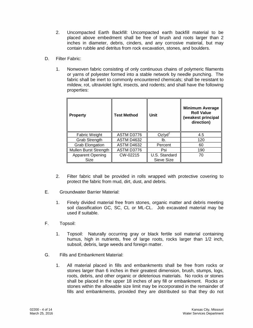
1. Nonwoven fabric consisting of only continuous chains of polymeric filaments
or yarns of polyester formed into a stable network by needle punching. The fabric shall be inert to commonly encountered chemicals; shall be resistant to mildew, rot, ultraviolet light, insects, and rodents; and shall have the following properties:
Property Test Method Unit Minimum Average
Roll Value (weakest principal
direction)
Fabric Weight ASTM D3776 Oz/yd2 4.5 Grab Strength ASTM D4632 lb. 120
Grab Elongation ASTM D4632 Percent 60 Mullen Burst Strength ASTM D3776 Psi 190
Apparent Opening Size
CW-02215 U.S. Standard Sieve Size
70
2. Filter fabric shall be provided in rolls wrapped with protective covering to protect the fabric from mud, dirt, dust, and debris.
E. Groundwater Barrier Material:
1. Finely divided material free from stones, organic matter and debris meeting soil classification GC, SC, CL or ML-CL. Job excavated material may be used if suitable.
F. Topsoil:
1. Topsoil: Naturally occurring gray or black fertile soil material containing
humus, high in nutrients, free of large roots, rocks larger than 1/2 inch, subsoil, debris, large weeds and foreign matter.
G. Fills and Embankment Material:
1. All material placed in fills and embankments shall be free from rocks or
stones larger than 6 inches in their greatest dimension, brush, stumps, logs, roots, debris, and other organic or deleterious materials. No rocks or stones shall be placed in the upper 18 inches of any fill or embankment. Rocks or stones within the allowable size limit may be incorporated in the remainder of fills and embankments, provided they are distributed so that they do not
02200 - 5 of 14 Kansas City, Missouri March 25, 2016 Water Services Department
interfere with proper compaction. Job excavated material meeting their requirements may be used.
PART 3 EXECUTION 3.2 General Guidelines
A. Excavations shall be restored to the level of the adjacent surfaces as soon as practicable. Unsupervised open excavations on public properties, including easements are not permitted. Any person involved with open excavation on public properties shall provide effective protection to the public.
B. Excavations in roadways shall be protected and secured in accordance with
existing federal, state and local codes and standards, including, but not limited to, the most current edition of the Manual of Uniform Traffic Control Devices.
C. Unsupervised excavations not within roadways shall be protected and secured. A
protective cover over an excavation shall be installed so that it can sustain the weight of any persons and/or objects placed upon it. The cover shall be fixed to the ground so it cannot be moved. Protective covers shall have no opening(s) or protuberance(s) of sufficient size to cause a fall and/or injury. Advance warning devices shall be installed as necessary.
D. Any excavation that is not covered shall be fenced in so that it surrounds the entire
excavation area and prevents entry. The fencing shall be a minimum of 42” in height. The fence shall be secured and upright at all times.
E. Protective excavation coverings and fences shall be inspected by the Contractor at
least daily to assure integrity. Protective excavation coverings and fences in heavy traffic areas shall be inspected more often as necessary.
F. Permits shall be secured prior to any work on public properties. In all instances the
Contractor agrees to perform all work in accordance with the permit and to indemnify and hold harmless the City from all liability, judgments, costs, expenses and claims growing out of damages or alleged damages, of any nature to any person or property arising out of performance or non-performance of said work or the existence of facilities and/or appurtenances thereof.
3.2 Surface Preparation
A. Clearing:
1. Tag or identify existing trees, shrubs, and landscape materials to be removed, and obtain CITY approval prior to removal.
2. Protect existing trees, plant life, and features that are to remain from damage
by construction operations.
3. Open burning of brush or debris will not be permitted unless the Contractor obtains a permit for open burning of trade wastes from the KCMO Environmental Health Division, Air Quality Program Manager.
02200 - 6 of 14 Kansas City, Missouri March 25, 2016 Water Services Department
4. Dispose of all cleared and grubbed materials.
Cutting Portland Cement Concrete Curbs and Pavement:
1. Cuts in curbs and pavements shall provide the minimum working space for
proper installation of pipe and appurtenances. Utilize a concrete saw to cut a clean groove to a minimum depth of 3 inches.
2. Curbs and concrete pavement excavated for pipelines shall be removed so
that a shoulder not less than 12 inches in width at any point is left between the cut edge of the pavement and the top edge of the trench. Trench width at the bottom shall not be greater than at the top and no undercutting will be permitted.
3. Where the trench parallels the length of curbs or sidewalks, and the trench
location is all or partially under the curb or walk, the entire structure shall be removed and replaced. Where the trench crosses surface construction (walks, curbs, etc.) the structures shall be removed and subsequently replaced between existing joints or between saw cuts. Pipeline crossings at existing concrete driveways shall not be open cut unless approved by CITY.
3.3 Trench Excavation
A. General:
1. Classification of excavated materials is not permitted. Excavation and trenching work shall include the removal and handling of all materials necessary to place the pipeline and appurtenances at the line and grade on the drawings, regardless of the type, character, composition, or condition of the material.
2. No more trench shall be opened than is necessary to expedite the Work.
Except where tunneling is required, all trench excavation shall be open cut from the surface.
B. Depth of Excavation:
1. Trenches shall be excavated to a depth sufficient to provide a minimum depth
of 42" backfill cover over the top of the pipe as indicated below. Sixteen inch and larger diameter water lines shall be provided a minimum of 60” backfill cover. Greater pipe cover depths may be necessary on vertical curves or to provide necessary clearance beneath existing pipes, conduits, drains, drainage structures, or other obstructions.
2. Pipe cover depth shall be measured vertically from the outside top of pipe to
finished ground or pavement surface elevation.
02200 - 7 of 14 Kansas City, Missouri March 25, 2016 Water Services Department
C. Trench Bottoms in Rock:
1. Rock excavations shall be carried to a minimum of six (6) inches below the bottom of the pipe. Granular embedment material as specified in this section and as shown in the Construction Detail Drawings shall be used to restore the trench bottom to the desired elevation and grade and to provide a uniform bearing and continuous support for the pipe along its entire length.
2. Prevent any portion of the pipe from coming to bear on solid rocks or boulders.
D. Blasting:
1. Blasting or other use of explosives for excavation will not be permitted without
obtaining a blasting permit from the KCMO Public Works Department and KCMO Fire Department.
2. Contractor shall provide a plan for preblast surveys, monitoring during blasting,
and post blast surveys to CITY prior to use of explosives.
3. All existing safety regulations, laws, and ordinances on the storage, transportation, and use of explosives shall be observed.
4. Blasting will be permitted only when proper precautions are taken for the
protection of persons, the work, private property, public utilities, and the public from damage or injury. Any damage done by blasting will be repaired.
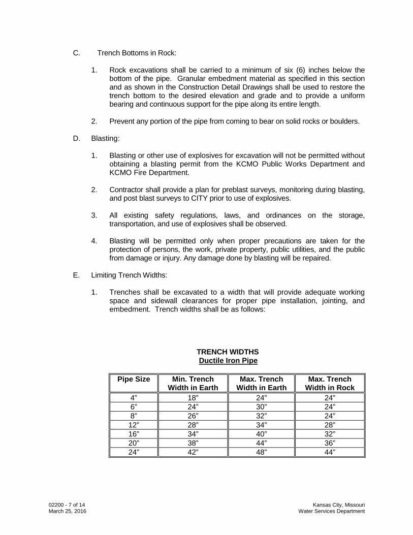
E. Limiting Trench Widths:
1. Trenches shall be excavated to a width that will provide adequate working
space and sidewall clearances for proper pipe installation, jointing, and embedment. Trench widths shall be as follows:
TRENCH WIDTHS
Ductile Iron Pipe
Pipe Size Min. Trench Width in Earth
Max. Trench Width in Earth
Max. Trench Width in Rock
4” 18” 24” 24” 6” 24” 30” 24” 8” 26” 32” 24” 12” 28” 34” 28” 16” 34” 40” 32” 20” 38” 44” 36” 24” 42” 48” 44”
02200 - 8 of 14 Kansas City, Missouri March 25, 2016 Water Services Department
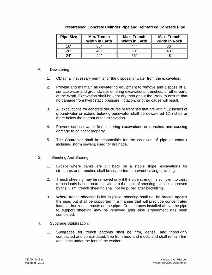
Prestressed Concrete Cylinder Pipe and Reinforced Concrete Pipe
Pipe Size Min. Trench Width in Earth
Max. Trench Width in Earth
Max. Trench Width in Rock
16” 36” 44” 36” 20” 40” 50” 40” 24” 44” 56” 48”
F. Dewatering:
1. Obtain all necessary permits for the disposal of water from the excavation.
2. Provide and maintain all dewatering equipment to remove and dispose of all surface water and groundwater entering excavations, trenches, or other parts of the Work. Excavation shall be kept dry throughout the Work to ensure that no damage from hydrostatic pressure, flotation, or other cause will result.
3. All excavations for concrete structures or trenches that are within 12 inches of
groundwater or extend below groundwater shall be dewatered 12 inches or more below the bottom of the excavation.
4. Prevent surface water from entering excavations or trenches and causing
damage to adjacent property.
5. The Contractor shall be responsible for the condition of pipe or conduit including storm sewers, used for drainage.
G. Sheeting And Shoring:
1. Except where banks are cut back on a stable slope, excavations for structures and trenches shall be supported to prevent caving or sliding.
2. Trench sheeting may be removed only if the pipe strength is sufficient to carry
trench loads based on trench width to the back of sheeting. Unless approved by the CITY, trench sheeting shall not be pulled after backfilling.
3. Where trench sheeting is left in place, sheeting shall not be braced against
the pipe, but shall be supported in a manner that will preclude concentrated loads or horizontal thrusts on the pipe. Cross braces installed above the pipe to support sheeting may be removed after pipe embedment has been completed.
H. Subgrade Stabilization:
1. Subgrades for trench bottoms shall be firm, dense, and thoroughly
compacted and consolidated; free from mud and muck; and shall remain firm and intact under the feet of the workers.
02200 - 9 of 14 Kansas City, Missouri March 25, 2016 Water Services Department
2. Subgrades for trench bottoms that are solid, but become mucky on top due to construction operations, shall be reinforced with clean crushed rock or gravel. The stabilizing material shall be spread and compacted to a depth of not more than 12 inches; the material shall be furnished and installed as specified for Granular Fills. The finished elevation of stabilized subgrades shall not be above subgrade elevations.
3. Soft areas of subgrade not capable of proper compaction shall be excavated
and backfilled with granular fill material compacted to 95% modified Proctor per ASTM D4253 and D4254.
I. Mechanical Excavation:
1. The use of mechanical equipment will not be permitted in locations where its
operation would cause damage to trees, buildings, culverts, or other existing property, utilities, or structures above or below ground. In all such locations, hand excavating methods shall be used.
2. Mechanical equipment used for trench excavation shall provide a smooth
excavation bottom and alignment with the pipe centered in the middle of the trench with adequate sidewall clearance. Undercutting the trench sidewall to obtain sidewall clearance will not be permitted.
J. Excavation Below Pipe:
1. Trenches shall be excavated to a sufficient depth to provide for the
installation of Embedment as indicated on Construction Detail Drawings No. 02200-1.
K. Bell Holes:
1. Bell holes shall provide adequate clearance for tools and methods used in
installing pipe. No part of any bell or coupling shall be in contact with the trench bottom, trench walls, or granular embedment when the pipe is jointed.
L. Drainage Maintenance:
1. Trenches across areas adjacent to drainage ditches or watercourses shall not
be backfilled prior to completion of backfilling the trench on the upstream side of the area, to prevent impounding water after the pipe has been laid. Bridges and other temporary structures required to maintain traffic across unfilled trenches shall be constructed and maintained by the Contractor. Backfilling shall be done so that water will not accumulate in unfilled or partially filled trenches. Remove material deposited in roadway ditches or other watercourses crossed by the line of trench after backfilling is completed. Restore the original section, grades, and contours of ditches or watercourses. Surface drainage shall not be obstructed longer than necessary.
02200 - 10 of 14 Kansas City, Missouri March 25, 2016 Water Services Department
M. Stream Crossings:
1. Stream crossings shall be constructed in accordance with Construction Detail Drawing No. 02200-2.
2. Pipe encasement, where required by the Drawings shall be in accordance
with specification Section 02320 and Construction Detail Drawings. 3. The construction of riprap for erosion prevention of ditch slopes shall be as
shown on the Construction Detail Drawings and indicated in Section 02273. 4. The Contractor shall furnish all labor, equipment, and materials, and perform
all Work as required for shoring, forming, dewatering, trenching, backfilling, riprap, concrete or steel, or any other items necessary in constructing stream crossings.
3.4 Fills and Embankment
C. General:
1. Embankments or fill materials shall be placed where indicated on the Drawings.
2. Fill and embankment materials shall be placed in horizontal layers a
maximum of eight (8) inches in uncompacted thickness. Material deposited in piles or windrows by excavating and hauling equipment shall be spread and leveled before compaction.
3. Each layer of material shall have the best practicable moisture content for
satisfactory compaction. The material in each layer shall be wetted or dried as required and thoroughly mixed to ensure uniform moisture content and adequate compaction. Each layer shall be thoroughly compacted to 95 percent of maximum density at optimum moisture content as determined by ASTM D698.
4. Wherever a pipeline is to pass through a fill or embankment, the fill or
embankment material shall be placed and compacted to an elevation not less than thirty-six (36) inches above the top of pipe elevation, and a trench shall be excavated in the embankment to permit placement of the pipe.
5. Granular Fills shall be provided where indicated on the Drawings. Granular
Fills shall be placed on suitably prepared subgrades and compacted by vibration. Granular Fills shall be compacted to not less than 95 percent relative density as determined by ASTM D1557.
6. Where pipes are installed in embankments containing ground water, granular
embedment material shall normally be omitted and the trench bottom shall be graded to provide uniform and continuous support for the pipe. The pipe shall be embedded in embankment material containing no rocks or stones. The embedment material shall be compacted as specified for the embankment.
02200 - 11 of 14 Kansas City, Missouri March 25, 2016 Water Services Department
3.5 Embedment and Backfill
A. Pipe Embedment:
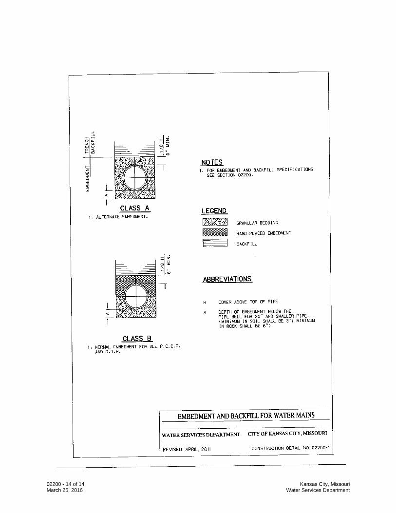
1. Embedment materials both below and above the bottom of the pipe, classes of embedment to be used, and placement and compaction of embedment materials shall conform to the requirements indicated on Figure 02200-1 and to the following supplementary requirements: a. Embedment material shall contain no cinders, clay lumps, or other
material which may cause pipe corrosion.
b. Embedment Classes:
i. Class A Bedding: Class A bedding shall be used for all pipes below paved street areas and when Polyvinyl Chloride Pipe is used.
ii. Class B Bedding: Class B Bedding shall be used for all pipelines except Polyvinyl Chloride Pipe in unpaved areas. Hand-placed embedment shall be finely divided job excavated material free from debris, organic material, and stones compacted to 95% maximum density per ASTM D698. Granular bedding material may be substituted for all or part of the type of embedment.
2. Placement and Compaction: Granular embedment material shall be spread
and the surface graded to provide a uniform and continuous support beneath the pipe at all points between bell holes or pipe joints.
3. Hand-Placed Embedment: Hand-placed embedment shall be placed in uniform
layers not more than 8" thick and compacted around water main. 4. After each pipe has been aligned, placed in final position on the embedment
material, and shoved home, sufficient pipe embedment material shall be deposited and compacted under and around each side of the pipe and back of the bell to hold the pipe in proper position and alignment during subsequent pipe jointing and embedment operations. Embedment material shall be deposited and compacted uniformly and simultaneously on each side of the pipe to prevent lateral displacement.
5. Granular Embedment shall be placed in maximum 6” layers and vibrated with
a mechanical probe type vibrator during placement to ensure that all spaces beneath the pipe are filled. Each lift of embedment material shall be compacted with a platform type vibrating compactor to at least 70 percent relative density as determined by ASTM D4253 and D4254.
6. Where soil is migrating into embedment, place filter fabric on the trench
surfaces so that it completely surrounds the embedment material. Joints shall be lapped 12 inches.
02200 - 12 of 14 Kansas City, Missouri March 25, 2016 Water Services Department
7. Groundwater Barrier: Interrupt continuity of embedment material by placing
low permeability Groundwater Barrier Material to impede passage of groundwater through the embedment. Groundwater Barrier Material shall be placed around vault structures with cast-in-place bases and compacted to 95% of maximum density and along trenches at intervals approved by CITY not to exceed 250 feet.
B. Trench Backfill:
1. Compacted Backfill: Compacted Backfill will be required for the full depth of
the trench above the embedment in the following locations:
a. Beneath pavements, driveways, curbs, gutters, walks, or other surface construction or structures.
b. Street, road, or highway shoulders. c. Established lawn areas, including parks.
2. Job Excavated Materials: Place in uniform layers not exceeding eight (8)
inches in uncompacted thickness. Each layer of material shall maintain optimum moisture content for compaction. The material in each layer shall be wetted or dried as required and mixed to ensure uniform moisture content and compaction. Increased layer thickness not to exceed 12 inches in uncompacted thickness may be permitted for non-cohesive material if the Contractor demonstrates to CITY satisfaction that the specified compacted density will be obtained. The method of compaction and the equipment used shall be appropriate for the material to be compacted and shall not transmit damaging shocks to the pipe. Job excavated material shall be compacted to 95 percent of maximum density at optimum moisture content, as determined by ASTM D698, or to 70 percent relative density, as determined by ASTM D4253 and D4254 when appropriate.
3. Graded Gravel Backfill: Place in uniform layers not exceeding twelve (12)
inches in uncompacted thickness. The backfill shall be compacted with a vibratory roller or platform vibrator to at least 70 percent relative density as determined by ASTM D4253 and D4254.
a. Groundwater Barriers (specified under pipe embedment) shall extend to
the top of the graded gravel backfill.
4. Uncompacted Backfill: Compaction of trench backfill above pipe embedment will only be required in designated locations and other locations where it is necessary to prevent future settlement.
a. Uncompacted backfill material above embedments shall be placed by
methods which will not cause excessive concentrated or unbalanced loads, shock, or impact on installed pipe, and which will not result in displacement of the pipe.
02200 - 13 of 14 Kansas City, Missouri March 25, 2016 Water Services Department
b. Prevent compact masses of stiff clay or other consolidated material more than 1 cubic foot in volume from falling into the trench.
c. Uncompacted trench backfill material containing rocks or rock
excavation detritus shall not be placed in the upper 18 inches of the trench, nor shall any stone larger than 6 inches be placed within 3 feet of the top of pipe.
3.6 Final Grading and Placement of Topsoil
A. After completing backfilling, grade areas to the required elevations, slopes, and contours. All cuts, fills, embankments, and other areas that have been disturbed or damaged by construction operations shall be surfaced with topsoil to a depth of at least 4 inches.
B. Use of graders or other power equipment will be permitted for final grading and
dressing slopes. Grade surfaces to provide effective drainage. Unless otherwise indicated, provide a slope of at least 1- percent.
C. Final grades and surfaces shall be smooth, even, and free from clods and stones,
weeds, brush, and other debris. 3.7 Disposal of Excess Materials
A. Excess excavated materials that are not utilized in trench backfill shall be disposed of at an approved site or landfill.
B. Excess earth from excavations may be distributed directly over the pipe trench and
within the pipeline right-of-way to a maximum depth of 6 inches above the original ground surface elevation along the trench centerline and sloping each way. Wasted material shall be carefully finished with a drag, blade machine, or other suitable tool to a smooth, uniform surface without obstructing drainage. Wasting of excess excavated material as described will not be permitted where the line of trench crosses or is within a railroad, public road, highway right-of-way or established lawn or other landscaped area. The disposal of waste and excess excavated materials, including hauling, handling, grading, and surfacing, shall be an obligation of the Contractor.
3.8 Maintenance
A. The Contractor shall be responsible for all settlement of backfill, fills, and embankments that may occur.
B. The Contractor shall make, or cause to be made, all repairs or replacements made
necessary by settlement within 30 days after notice from the CITY.
END OF SECTION
02200 - 14 of 14 Kansas City, Missouri March 25, 2016 Water Services Department
02320 - 1 of 7 Kansas City, Missouri April 11, 2014 Water Services Department
SECTION 02320
UTILITY CASINGS
PART 1 GENERAL 1.1 Section Description
A. This section provides for installation of casing pipe at locations shown on the Drawings to protect the water main from surface loadings.
1.2 Section Includes
A. Steel Casing Pipe B. Reinforced Concrete Pipe (RCP) Casing Pipe C. FRP Casing Pipe D. Accessories
E. PVC Casing Pipe near gas mains
1.3 Related Sections
A. Section 01300 – Submittals B. Section 01600 – Materials and Equipment C. Section 02200 – Excavation and Trenching D. Section 02618 – Ductile Iron Pipe Water Main E. Section 02669 – Thrust Restraints
1.4 References
A. API RP1102 - Recommended Practice for Liquid Petroleum Pipelines Crossing Railroads and Highways.
B. API 1104 - Standard for Welding Pipelines and Related Facilities. C. ASTM A36 - Structural Steel. D. ASTM A570 - Hot-Rolled Carbon Steel Sheet and Strip, Structural Quality. E. ASTM C33 - Standard Specifications for Concrete Aggregates. F. ASTM C76 - Standard Specifications for Reinforced Concrete Culvert, Storm Drain,
and Sewer Pipe.
02320 - 2 of 7 Kansas City, Missouri April 11, 2014 Water Services Department
G. ASTM C361 - Standard Specifications for Reinforced Concrete Low-Head
Pressure Pipe. H. AWWA C200 - Steel Water Pipe 6 Inches and Larger. I. AWWA C206 - Field Welding of Steel Water Pipe.
J. SSPC SP3 - Power Tool Cleaning.
K. AWWA C900 and C-905 – Polyvinylchloride Pipe
1.5 Submittals
A. Follow the procedures for submittals provided in Section 01300 – Submittals. B. Submit descriptive and engineering data for:
1. Casing pipe material, coatings and linings. 2. Pipe alignment skids. 3. Guide spacer bands. 4. Restrained casing spacers. 5. End seals.
1.6 Delivery, Storage, and Handling
A. Follow the provisions for the delivery, storage, protection and handling projects to and at site provided in Section 01600 - Material and Equipment.
B. Accept piping on site. Inspect for damage and inventory.
PART 2 PRODUCTS 2.1 Materials
A. Steel Casing Pipe:
1. New, smooth wall, welded steel pipe fabricated from ASTM A36 plate or ASTM A570 sheet with a minimum yield point of 248 MPa (36,000 psi), conforming to AWWA C200.
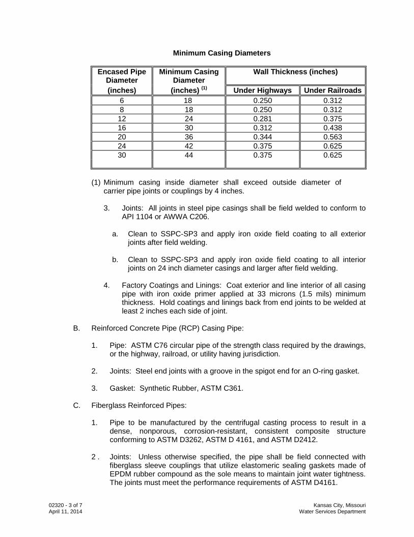
2. Casing Thickness: The following table provides a listing of minimum casing
diameters and thickness:
02320 - 3 of 7 Kansas City, Missouri April 11, 2014 Water Services Department
Minimum Casing Diameters
Encased Pipe Diameter
Minimum Casing Diameter
Wall Thickness (inches)
(inches) (inches) (1) Under Highways Under Railroads 6 18 0.250 0.312 8 18 0.250 0.312 12 24 0.281 0.375 16 30 0.312 0.438 20 36 0.344 0.563 24 42 0.375 0.625 30 44 0.375 0.625
(1) Minimum casing inside diameter shall exceed outside diameter of
carrier pipe joints or couplings by 4 inches.
3. Joints: All joints in steel pipe casings shall be field welded to conform to API 1104 or AWWA C206.
a. Clean to SSPC-SP3 and apply iron oxide field coating to all exterior
joints after field welding. b. Clean to SSPC-SP3 and apply iron oxide field coating to all interior
joints on 24 inch diameter casings and larger after field welding.
4. Factory Coatings and Linings: Coat exterior and line interior of all casing pipe with iron oxide primer applied at 33 microns (1.5 mils) minimum thickness. Hold coatings and linings back from end joints to be welded at least 2 inches each side of joint.
B. Reinforced Concrete Pipe (RCP) Casing Pipe:
1. Pipe: ASTM C76 circular pipe of the strength class required by the drawings,
or the highway, railroad, or utility having jurisdiction. 2. Joints: Steel end joints with a groove in the spigot end for an O-ring gasket. 3. Gasket: Synthetic Rubber, ASTM C361.
C. Fiberglass Reinforced Pipes:
1. Pipe to be manufactured by the centrifugal casting process to result in a
dense, nonporous, corrosion-resistant, consistent composite structure conforming to ASTM D3262, ASTM D 4161, and ASTM D2412.
2 . Joints: Unless otherwise specified, the pipe shall be field connected with
fiberglass sleeve couplings that utilize elastomeric sealing gaskets made of EPDM rubber compound as the sole means to maintain joint water tightness. The joints must meet the performance requirements of ASTM D4161.
02320 - 4 of 7 Kansas City, Missouri April 11, 2014 Water Services Department
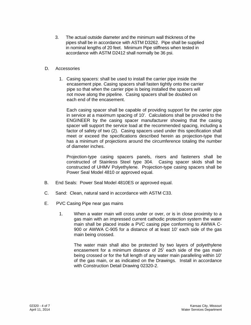
3. The actual outside diameter and the minimum wall thickness of the pipes shall be in accordance with ASTM D3262. Pipe shall be supplied in nominal lengths of 20 feet. Minimum Pipe stiffness when tested in accordance with ASTM D2412 shall normally be 36 psi.
D. Accessories
1. Casing spacers: shall be used to install the carrier pipe inside the encasement pipe. Casing spacers shall fasten tightly onto the carrier pipe so that when the carrier pipe is being installed the spacers will not move along the pipeline. Casing spacers shall be doubled on each end of the encasement.
Each casing spacer shall be capable of providing support for the carrier pipe in service at a maximum spacing of 10’. Calculations shall be provided to the ENGINEER by the casing spacer manufacturer showing that the casing spacer will support the service load at the recommended spacing, including a factor of safety of two (2). Casing spacers used under this specification shall meet or exceed the specifications described herein as projection-type that has a minimum of projections around the circumference totaling the number of diameter inches. Projection-type casing spacers panels, risers and fasteners shall be constructed of Stainless Steel type 304. Casing spacer skids shall be constructed of UHMV Polyethylene. Projection-type casing spacers shall be Power Seal Model 4810 or approved equal.
B. End Seals: Power Seal Model 4810ES or approved equal.
C. Sand: Clean, natural sand in accordance with ASTM C33.
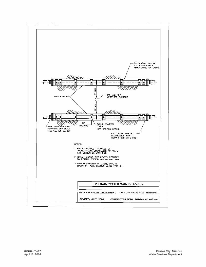
E. PVC Casing Pipe near gas mains
1. When a water main will cross under or over, or is in close proximity to a gas main with an impressed current cathodic protection system the water main shall be placed inside a PVC casing pipe conforming to AWWA C-900 or AWWA C-905 for a distance of at least 10’ each side of the gas main being crossed. The water main shall also be protected by two layers of polyethylene encasement for a minimum distance of 25’ each side of the gas main being crossed or for the full length of any water main paralleling within 10’ of the gas main, or as indicated on the Drawings. Install in accordance with Construction Detail Drawing 02320-2.
02320 - 5 of 7 Kansas City, Missouri April 11, 2014 Water Services Department
2.2 Quality Assurance
A. Contractor: Company specializing in the installation of the Products specified in this Section with minimum three years documented experience.
PART 3 EXECUTION 3.1 Installation
A. All work shall meet the minimum requirements of API RP1102, and the highway, railroad, or utility having jurisdiction. Installation shall be subject to their inspection and approval.
B. Install Casing Pipes:
1. Boring: Continuous flight auger, pneumatic or hydraulic jacking, or method
approved by WSD. Reinforce leading end of casing with jacking band. 2. Install to line and grade indicated on the Drawings. 3. Excavate working pits of adequate size to provide safe working conditions
and in such a manner as not to disrupt traffic or damage the roadway grade or surface.
4. Casings rejected due to misalignment or other failures shall be abandoned in
place and filled with grout. Casing pipe shall not be recovered for reuse. 3.2 Casing Spacers
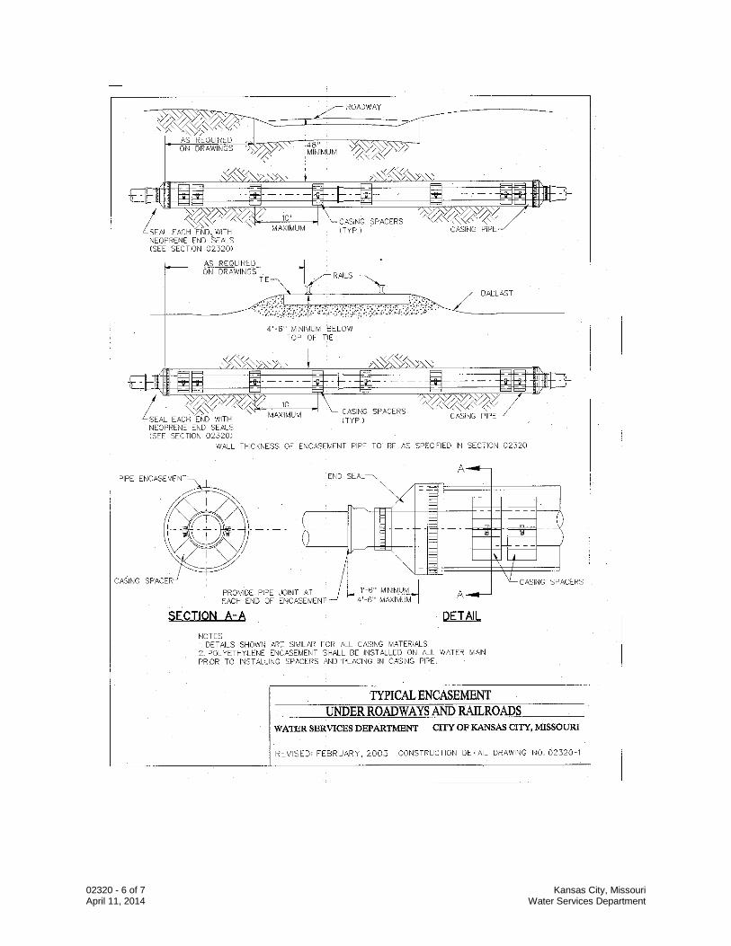
A. Furnish casing spacers for pipe alignment guides as indicated on the Construction Detail Drawing No. 02320-1 for all carrier pipe to be installed in casing.
1. Outside diameter of spacer to be sized slightly smaller than casing pipe
inside diameter to limit carrier pipe movement. 2. Install in accordance with spacer manufacturer’s recommendations.
3.3 End Seals
A. Install end seals as indicated on the Construction Detail Drawing No. 02320-1 and as follows:
1. After inside of casing has been thoroughly cleaned. 2. After carrier pipe has been permanently placed inside casing.
END OF SECTION
02320 - 6 of 7 Kansas City, Missouri April 11, 2014 Water Services Department
02320 - 7 of 7 Kansas City, Missouri April 11, 2014 Water Services Department
02506 – 1 of 12 Kansas City, Missouri Revised 7/24/2015 Water Services Department Standards and Specifications
SECTION 02506 - WATER UTILITY FACILITIES PART 1 – GENERAL 1.1 SCOPE. This section covers Water Services Department’s Standards and Specifications for Water Main Extensions and Relocations. These specifications shall be used for the construction of water mains except for the sections, which have been modified and included herein. The Work to be performed under this section consists of furnishing all labor, materials (except those materials specifically listed under MATERIALS FURNISHED BY OWNER), equipment, tools, superintendence, and all services necessary to perform the Work, complete with all appurtenances:
A. The contractor shall notify Water Services Department, Inspection and Construction Division at least 2 working days prior to starting work on water utility and facilities.
B. The Contractor shall provide a 3-year maintenance bond in accordance with the
requirements of the Water Department for all water line construction. 1.2 CONTRACT SPECIFICATIONS
A. The work shall conform to these Project Requirements and to the latest revision of the Standards and Specifications for Water Main Extensions and Relocations which is made a part hereof by reference.
B. The term “Engineer” as used in the aforesaid Standards and Specifications and in this
section, Section 02506 of the Project Manual, only, shall mean the Engineering Services Division of the Water Services Department of the City, or any engineer or agent designated by the DIRECTOR of the Water Service Department in responsible charge of the water line Work.
C. The Standards and Specifications for Water Main Extensions and Relocations is available
on the City website at http/www.kcmo.org. The hypertext path to click is as follows: Departments; Water Services; kcwaterservices.org (Department link); customer service; Resources; Standards and Specifications for Water Main Extensions and Relocations
PART 2 – PRODUCTS 2.1 MATERIALS FURNISHED BY THE OWNER
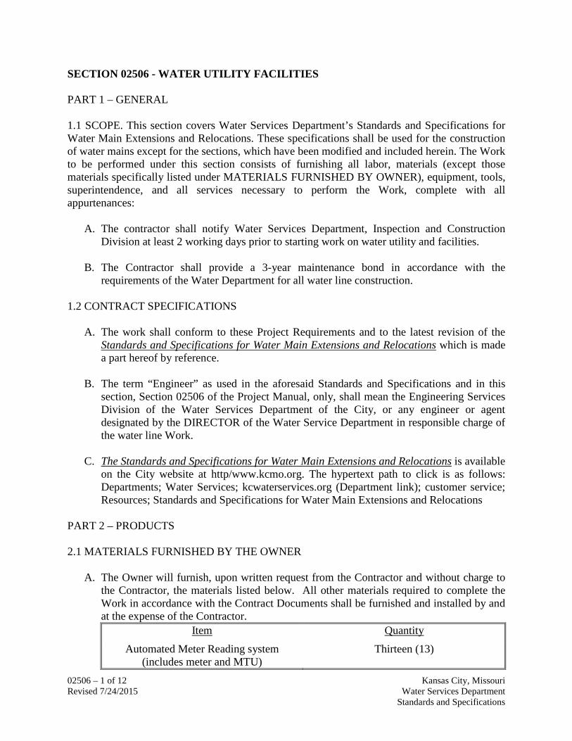
A. The Owner will furnish, upon written request from the Contractor and without charge to the Contractor, the materials listed below. All other materials required to complete the Work in accordance with the Contract Documents shall be furnished and installed by and at the expense of the Contractor.
Item Quantity
Automated Meter Reading system (includes meter and MTU)
Thirteen (13)
02506 – 2 of 12 Kansas City, Missouri Revised 7/24/2015 Water Services Department Standards and Specifications
B. All material furnished by the Owner which is damaged, lost or stolen after its acceptance by the Contractor shall be replaced at the expense of the Contractor with like material purchased from the Owner.
C. The Contractor, or his authorized representative, shall sign a bill of receipt for all
materials withdrawn from the Water Services Department Stores.
D. All materials withdrawn from the Water Services Department Stores that are not incorporated in the Work shall be returned to the Water Services Department Stores. All such material not returned shall be charged to the Contractor and deduction therefore shall be made from the final payment estimate.
2.1 CONNECTIONS TO EXISTING MAINS
A. The Contractor shall furnish and install all fittings necessary for connections to the existing water mains at the locations shown on the Plans. No connections to existing mains shall be started without prior approval of the Director. Scheduling of water main shuts and connections to existing water main shall be discretion of Water Services.
B. It shall also be the responsibility of the Contractor to make any and all excavations and
backfill as required, and furnish all labor, equipment, and material necessary to complete the connections as detailed on the Plans. The Contractor shall maintain, barricade, repair, restore, and protect all excavations and disturbed areas. All bends, tees, etc., shall be provided with adequate backing by the Contractor as required in Section 02669 – Thrust Restraints of the Standards and Specifications.
1. Temporary Service
a. The Contractor shall notify all Water Services Department customers affected by
the Work of making the connections as to the time of day and the span of time required to make said connections. When the closing of a valve to make the connections will terminate water service to a customer (S), the Contractor shall arrange to supply temporary service and schedule the time which is most convenient to the customer (S) for making the connection. No extra compensation will be allowed for providing temporary service or making the connection at a time other than normal working hours.
b. When temporary water supply is not possible, valve shut duration shall be less
than 4 hours. 2.2 BACKFILL All backfill in sidewalk and street areas shall be thoroughly compacted in conformance with APWA-KCMO Section 02602.3 “Construction Details.”
02506 – 3 of 12 Kansas City, Missouri Revised 7/24/2015 Water Services Department Standards and Specifications
2.3 FACILITIES
A. Water. The Owner will furnish without charge all necessary water for filling, flushing, and testing the completed line and other construction requirements. The Contractor shall make arrangements with the Owner for all water used. Use of City's water facilities shall be at the direction of the Water Services Department so that water service to customers served by the facilities is not impaired. Under any conditions, water shall not be wasted. Any water furnished by the Owner must be obtained from the Owner's existing main.
B. All material and service needed to obtain water for construction purposes shall be
provided by the Contractor at his sole cost and expense.
C. Operation of Existing Valves
1. Valves on Transmission Mains
The operation of all valves on the City’s existing transmission system shall be performed or supervised by the City. The Contractor shall not operate valves on the Water Services Department’s transmission mains (any main larger than 12-inches) without direct supervision of the City. If the Contractor desires the operation of any transmission main valves, he shall make a written request of the Water Services Department for such operation. For transmission main shuts, Contractor shall give City at least one week’s notice so a temporary test shut can be scheduled and conducted to ensure a tight shut can be made. Contractor shall assist with test shuts and main shuts as requested by City including, but not limited to, filling out and distributing shut notices and operation of valves under direct supervision of the City. The hydrant branch valves on transmission mains may be operated in the presence of a representative of the Water Services Department with no official advance notification.
2. Valves on Distribution Mains
The Contractor has the option to perform test shuts and main shuts on the City’s water distribution mains (any main 12” or smaller) without direct supervision and coordination of the City at no extra cost to the City. However, all test shuts and main shuts require the City’s approval. The request form for test shuts and main shuts shall be sent to the City’s Project Manager and Area Supervisor at least one week prior to needing the shut. The Contractor will be responsible for notifying all residents who will be affected which includes, but is not limited to, filling out and distributing shut notices. The Contractor must still coordinate with both the City’s resident inspector and Project Manager. The Contractor must follow City’s standard procedures when shutting, filling, and flushing distribution mains, including but limited to, notifying City’s Dispatch Office.
If the Contractor chooses not to perform the test shuts and main shuts on the City’s water distribution mains without direct supervision and coordination of the City, he must schedule all shuts with the City’s resident inspector. For main shuts, Contractor shall give City at least two weeks’ notice so a test shut can be scheduled and conducted.
02506 – 4 of 12 Kansas City, Missouri Revised 7/24/2015 Water Services Department Standards and Specifications
Contractor shall assist with test shuts and main shuts on distribution mains as requested by City including, but not limited to, filling out and distributing shut notices and operation of valves and hydrants under direct supervision of the City.
D. Power. All power for lighting, operation of the Contractor's plant or equipment, or for
any other use which may be required for proper completion of the Work to be performed shall be provided by the Contractor at his sole cost and expense.
PART 3 – EXECUTION 3.1 WATER SERVICE PERMITS AND FEES
A. The Contractor will be required to obtain Water Service Permits as required in the Rules and Regulations of the Water Services Department . However, the Contractor will not be required to pay any permit fees for service permits or service taps. The Rules and Regulations of the Water Services Department is available on the City website at http/www.kcmo.org. The hypertext path to click is as follows: Departments; Water Services; kcwaterservices.org (Department link); customer service; Resources; Rules and Regulations.
B. The Contractor will be required to pay all permit fees of other City Departments, as
identified in the General and Supplementary Conditions. 3.2 POSITION, Line and Grade
A. A Registered Land Surveyor must set control points for the work. Horizontal and vertical control points shall be established using State Plane Coordinates, “Missouri Coordinate System of 1983, West Zone” and NAVD 88 Datum. The Contractor is responsible for hiring a Registered Land Surveyor for this work. All additional survey, layout, and measurement work shall be the responsibility of the Contractor.
B. Contractor shall provide qualified and experienced staff, equipment and materials required to complete the survey, layout, and measurement work. Contractor shall also furnish necessary labor, equipment, and materials to establish or designate control points when required, establish construction easement boundaries, and check survey, layout, and measurement work. Offset stakes shall be provided at a minimum of 100 feet along the water line and at all appurtenances and fittings. Offset stakes will be at 50’ intervals if curbs are not in place.
C. Contractor shall coordinate survey work and shall inform Engineer and WSD in advance
of the location and schedule of all survey work.
D. Contractor shall provide to WSD complete survey cut sheets containing Water Main Stationing, State Plane Coordinates in U.S. Survey Feet (expressed in feet and decimals of a foot). These coordinates must conform to the “Missouri Coordinate System of 1983, West Zone”. Cut notes must also include, Top of Pipe Elevations, Off-Set Hub distances
02506 – 5 of 12 Kansas City, Missouri Revised 7/24/2015 Water Services Department Standards and Specifications
with elevations of hub, Finish Grade at Hydrant Sets, Benchmark Elevations, Height of Instrument, and all main shots, in NAVD 88 datum. Stationing coordinates and elevations must match drawings “approved for construction” by WSD, and shall be indicated for every fitting and every station at maximum distances of 50 feet along the water line. Water mains to be installed with deflections shall have coordinate points established at the beginning point of deflection and at the ending point of deflection.
E. The cut sheets shall be sealed by a Registered Land Surveyor and must be submitted to WSD for approval a minimum of 2 working days prior to commencement of any Work included on the cut sheets. Saturdays, Sundays, or any Legal Holiday observed by the WSD are not to be included in the 2 working days period. Work shall not proceed if survey cut sheets are not approved by WSD.
F. The Contractor shall maintain one set of approved cut sheets at the project site and shall keep them continually updated for record purposes.
3.3 DISINFECTION
A. All disinfection work shall be in strict conformance with Section 02675 – Water Main Testing, Disinfection, and Dechlorination of the Standards and Specifications, with the following:
B. After the mains have been properly prepared, the Contractor will disinfect the mains, at
no additional cost to the Water Services Department. The Contractor will furnish all necessary assistance for the operation of valves, etc.
C. After dechlorination and final flushing, and prior to putting the main into service, a
passing Bac-T test shall be made on the main by the City. If the Bac-T test fails, the Contractor shall disinfect the main again. The Contractor shall do all the remaining work such as backfilling, paving, etc, which is necessary before the mains are put into service.
3.4 WATER SERVICES AND RECONNECTIONS
A. All existing service lines connected to existing mains that are to be abandoned shall be disconnected from said mains and reconnected to the new mains. These reconnections shall be made by the Contractor.
B. The Contractor will perform only one water service transfer at a time. After the
reconnection, the immediate area will be prepared for sod restoration before the Contractor is permitted to begin additional transfers.
C. If the Contractor chooses to use multiple crews for water service transfers, one crew
may perform the transfer of the water services while another crew performs restoration. Cleanup must be completed on all water service transfers each day.
02506 – 6 of 12 Kansas City, Missouri Revised 7/24/2015 Water Services Department Standards and Specifications
D. Installation of water service lines beneath streets and driveways shall be done by drilling or approved trench less methods unless rock or other site conditions require open cut excavations.
E. Contractor will replace all non-copper service connections with Type “K” copper (with
like size, ¾” minimum) from the main to curb stop. Existing copper service connections can be spliced to extend the existing service to the new main. If a shutoff does not exist within street right-of-way, a curb stop and box shall be installed at a location selected by Water Services Department.
F. The Contractor shall furnish all material, equipment, and labor for the complete installation in accordance with the Rules & Regulations of the Water Services Department. No service taps will be permitted until the new main is put in service. Existing water meters and tiles or curb stops that require relocation, either vertically or horizontally, because of construction, shall be relocated by the Contractor.
G. Meter and curb stop relocations include furnishing and installing new meter pit, new
meter yoke, new curb stop, new curb box, new fittings, and all new appurtenances as required by the latest Rules &Regulations of the Water Services Department including any required upgrades to the existing service. Contractor shall coordinate with Water Services for removal and installation of new meter so as to minimize period when customer will be out of service. No additional payment to the contractor shall be allowed for any water services meter and curb stop relocations.
H. Service taps to the main shall be made in accordance with Rules & Regulations of the
Water Services Department with the following exceptions: Replace Section 4.02 (a) with “(a) Tapping shall be performed by the Contractor.”
I. Water meter and valve castings (curb stops or boxes) shall be relocated as necessary to match the new grades. The number of water meter or valve castings and water service line relocations are approximate only, and the actual quantities will be adjusted during construction.
3.5 WATER METER, VALVE AND CUT-OFF ADJUSTMENTS
A. Water Meter Adjustment. Adjust water meters as necessary in conformance with the Rules & Regulations of the Water Services Department as published by the Water Department of Kansas City, Missouri. The completed work shall be subject to the approval of the Director of the Water Department.
B. Water Valve and Cut-Off Adjustment. Water valves and water service cut-offs which are affected by the work shall be adjusted as necessary to conform with the " Rules & Regulations of the Water Department" as published by the Water Department of Kansas City, Missouri. Once adjusted to finish grade, and following the installation of sod, each water valve box shall be blown clear of debris with compressed air. The Contractor shall
02506 – 7 of 12 Kansas City, Missouri Revised 7/24/2015 Water Services Department Standards and Specifications
be responsible for the protection of surrounding structures and/or vehicles which may be affected by this procedure. The completed work shall be subject to the approval of the Director of the Water Services Department.
C. Covers and Stems. Metal Water Meter, Valve Covers, and Stems shall be used in any walking or driving surface.
D. Meter in House. Provide labor, equipment and material to perform the following work to
reconnect the service lines for the properties with existing meters in the building as shown on the drawings. The Work shall be coordinated with the property owners and tenants. Contractor shall remove the existing water meter inside of the building and install new plumbing to replace the gap left by the removal of the water meter. All work inside the building shall be performed by a licensed plumber. Contractor shall replace existing service connection and service line as shown in the plans. Contractor shall notify the Engineer or City’s representative seven (7) days prior to installation of meter tile, meter -yolk and the first valve. Per Kansas City Water Services’ Rules and Regulations for Water Main Extensions and relocations, Water Services Department will provide and install Automated Meter Reading Systems (includes meter and MTU) where new meters are to be installed as shown in the plans.
1. Right of Entry: Contractor shall obtain written City’s right of entry permission, signed by the property owner for all inside private plumbing connection work, to the outside of the building. Contractor shall also obtain a document signed by the property owner accepting the completed private plumbing work within the building and to the meter. Authorized right-of-entry document shall be provided to the City by the Contractor, before commencement of work. Upon receipt and approval of the Right of Entry form, the Contractor shall commence work.
2. Meter Delivery: Removed meters shall be delivered by the Contractor to Water Services Department at an agreed upon location.
3.6 CONSTRUCTION SEQUENCE
A. No main will be considered substantially complete until the trenching, pipe laying, bedding, backfill, compaction and clean up are complete. In addition the main must be pressure/leakage tested and disinfected, flushed and services transferred. Service transfers, if any, are to be undertaken as soon as the main is accepted, and are to be completed before another main is started, unless multiple crews are working on the project simultaneously. Construction may not begin on subsequent mains until work on the first main is considered complete. If multiple crews are working on the project the pipe laying crews may not work more than one main ahead of the crews conducting service transfers. Where a main is constructed in established lawns, clean up must be performed before the next main is begun. (Lawn areas must be ready to accept sod)
02506 – 8 of 12 Kansas City, Missouri Revised 7/24/2015 Water Services Department Standards and Specifications
3.7 SETTING FIRE HYDRANTS
A. Setting of the fire hydrants shall be in strict conformance with Section 02645 – Hydrants, Blowoff and Flushing Assemblies of the Standards and Specifications, with the following;
B. All new hydrant settings shall be as shown on the Plans and shall include all necessary
excavation and backfill to make the installation complete. The area around each hydrant and hydrant valve cover shall be thoroughly compacted to prevent settlement of these areas.
C. The Contractor will locate the installation point of each hydrant as shown on the Plans,
but not less than 2’ from back of curb to face of hydrant. The Contractor shall furnish all labor and material necessary in laying out the Work. The Contractor shall be responsible for setting any offset stakes he may require. The Engineer shall approve the staked location of each hydrant before its installation.
3.8 STREAM CROSSINGS
A. Stream and drainage ditch crossings shall conform to the applicable Standards and Specifications and details shown on the Plans.
B. The trench width shall be as required for proper pipe installation and the trench depth
shall be as required to give minimum cover shown on the Plans. Pipe encasement, where required, shall be in accordance with the Standards and Specifications and placed as indicated on the Plans.
C. The construction of riprap for erosion prevention of ditch slopes will be required at
locations shown on the Plans.
D. The rock used for riprap shall be hard durable stone, not less than fifteen (15) inches thick, and shall be placed in mortar to provide a neat, uniform surface.
E. The Contractor shall furnish all labor, equipment, and materials, and perform all work
necessary to construct water main stream crossings as required. No extra payment will be allowed for shoring, forming, dewatering, trenching, backfilling, rip-rap, concrete or steel, or any other items necessary to complete stream or ditch crossings.
3.9 SUBMITTALS
A. Schedule of Values
Before submission of the first Application for Payment, Contractor shall prepare and submit to Engineer for review a Schedule of Values. The submittal of the Schedule of Values, showing the estimated quantity and value of each kind of work, shall be acceptable before the Application for Payment is prepared.
02506 – 9 of 12 Kansas City, Missouri Revised 7/24/2015 Water Services Department Standards and Specifications
B. Shop Drawings and Engineering Data
1. Shop Drawings and engineering data covering all equipment, fabrications, and
building materials which will become a permanent part of the work under this Contract shall be submitted to Engineer for review, at the Engineer’s address given in the Agreement. The data shall include drawings and descriptive information in sufficient detail to show the kind, size, anchorages, and supports required; performance characteristics; and dimensions needed for installation and correlation with other materials and equipment.
2. All submittals, regardless of origin shall be stamped with the approval of Contractor and identified with the name and number of this Contract, Contractors name, and references to applicable specification paragraphs and Contract Drawings. Each submittal shall indicate the intended use of the item in the work. When catalog pages are submitted, applicable items shall be clearly identified and inapplicable data crossed out. The current revision, issue number, and date shall be indicated on all drawings and other descriptive data.
3. Contractor’s stamp of approval is a representation to Owner and Engineer that Contractor accepts full responsibility for determining and verifying all quantities, dimensions, field construction criteria, materials, catalog numbers, and similar data, and that he has reviewed and coordinated each submittal with the requirements of the work and the Contract Documents.
4. Contractor shall accept full responsibility for the completeness of each submission.
When an item consists of components from several sources, Contractor shall submit a complete initial submittal including all components.
5. All Deviations from the Contract Documents shall be identified on each submittal and shall be tabulated in Contractor’s letter of transmittal. Such submittals shall, as pertinent to the deviation, indicate essential details of all changes proposed by Contractor (including modifications to other facilities that may be a result of the deviation) and all required piping and wiring diagrams.
6. Three (3) copies of each drawing and necessary data shall be submitted to the Engineer. Engineer will return two marked copies to Contractor. Facsimile (fax) copies will not be acceptable. Engineer will not accept submittals from anyone but Contractor. Submittals shall be consecutively numbered in direct sequence of submittal and without division by subcontracts or trades.
C. Project Records Documents
1. Contractor shall maintain in a safe place at the project site one continually updated record copy of all Drawings, Standards and Specifications, Addenda, Shop Drawings, Written Amendments, Change Orders, Work Change Directives, written interpretations or
02506 – 10 of 12 Kansas City, Missouri Revised 7/24/2015 Water Services Department Standards and Specifications
clarifications of the contract documents, survey information (including approved cut sheets), and all other documents relevant to the Work. All such documents shall be kept in good condition and order, and shall be continuously updated to indicate all changes made during construction. No work shall be allowed in the absence of these record documents.
2. Upon completion of the work at the project site, the Contractor shall submit to the WSD
all Record Documents. Record drawing submittals, that are a part of the Record Documents, shall include one paper copy, one reproducible copy (on Mylar or vellum), and one electronic copy on computer disc of the updated drawings in the latest version of Microstation® or AutoCAD®. The disc shall include all information necessary to edit and plot the drawings, and shall be labeled with the Project Name, WSD Project Number, WSD Work Order Number, WSD Drawing Number, and date of publication. All measurements on the Record Drawings must be updated to indicate the true location of the work as it was actually constructed in the field. The Record Drawings for water mains must Include references for all beginning and ending points, bends, hydrants, valves, tees, fittings, and beginning and ending points of deflection of water mains indicated in State Plane Coordinates in U.S. feet (expressed in feet and decimals of a foot). The coordinates must conform to the “Missouri Coordinate System of 1983, West Zone”. State wide Missouri Geographical Reference System monuments, Kansas City Metro Control Project monuments, Certified Land corners used as references to determine State Plane coordinates, and all control monuments used in the survey work must be listed with reference ties shown on the Record Drawings. The Record Drawings must indicate the elevations of the finished grade or improvements and the top of the water main at every fitting and Station at maximum spacing of 50’ along the water main. All elevations shall be indicated in NAVD 88 Datum (in feet and decimals of a foot). Every sheet of the Record Drawings must be reviewed and sealed by a Registered Land Surveyor, licensed in the state of Missouri and must include the following statement on the title block inside the box marked ”for WSD use” and in close proximity to the Registered Land Surveyor’s seal::
“Each sheet of these Record Drawings and attached Survey Cut Sheets for the Work have been reviewed and approved by the Registered Land Surveyor whose seal is affixed to this Record. The horizontal control, coordinates, and elevations shown on these Records are accurate and are based on the Missouri Coordinate System of 1983, West Zone and NAVD88 datum. These Records have been revised, as required in Section 01000, 1.20 of the Standards and Specifications for Water Main Extensions and Relocations, under my personal supervision to show the true and accurate measurements of the work as it was actually constructed.”
The Contractor must also sign each sheet of the documents with the following certification:
“I hereby certify that this Record correctly depicts the Work constructed as to size, horizontal and vertical location, and grade as shown
02506 – 11 of 12 Kansas City, Missouri Revised 7/24/2015 Water Services Department Standards and Specifications
on the approved construction drawings or their revision. The Work was done in accordance with these Records and the current version of the Standards and Specifications for Water Main Extensions and Relocations.” Contractor: ________________________ Date: __________ Name (print):________________________ Title: __________ Signature: _________________________
3. As part of the Project Record Documents, Contractor shall compile specific information
about each valve and hydrant installed in the project, and complete forms provided by the WSD. Information for each valve and hydrant shall include location and ties, number of turns (valves) make and type, date of installation, and other descriptive information on the standard WSD forms.
4. The WSD will review the submitted Record Documents and determine their adequacy prior to final acceptance of the Work. Record Documents determined to be inadequate will be returned to the Contractor for required revisions or additions. The Contractor will correct all inadequacies and make all additions required to make the Record Documents acceptable to the WSD. The Record documents shall be an integral part of the work guaranteed by the Contractor’s Performance and Maintenance Bond. If during the three year maintenance period WSD determines that further revisions or corrections are necessary to make the Record Documents accurate, the Contractor, at no cost to WSD will make or cause the revisions or corrections to be made.
3.10 PAYMENT
A. All labor, materials and equipment necessary to complete Water Main Replacement and Relocation and Water Service Line Relocation from Main to Curb Box or as shown in the plans, shall be included in the lump sum Bid price. Such payment shall be considered as full compensation for all labor, equipment, and materials required to complete the following work in accordance with the Contract Drawings and Specifications regardless of scope changes or differing site conditions.
1. All water distribution mains, including all pipes, valves, fittings, hardware,
polyethylene encasement–installed and successfully tested, disinfected, and connected to existing water distribution system.
2. All hydrant assemblies installed, including all pipes, valves, fittings, hardware, and
polyethylene encasement.
3. All water service connections and appurtenances transferred, including locating the service line, trenching, pipe, curb stop valves and boxes, and all fittings resulting in an operable water service conforming to the Plumbing Code.
02506 – 12 of 12 Kansas City, Missouri Revised 7/24/2015 Water Services Department Standards and Specifications
4. All pavement restoration, PCC driveway restoration, sidewalk, and curb ramp restoration Work associated with the water main or water service line relocation that is required to complete the water main or water service line relocation Work from the main to the curb box.
END OF SECTION
02575 - 1 of 4 Kansas City, Missouri April 11, 2014 Water Services Department
SECTION 02575
SURFACE RESTORATION PART 1 GENERAL 1.1 Section Description
A. This section provides replacement of sidewalks, curbs, and pavement removed for water main construction operations.
1.2 Section Includes
A. Embedment and Backfill
B. Roadway Surfacing
C. Brick or other Paver Material
D. Sidewalk 1.3 Related Sections
A. Section 01300 – Submittals
B. Section 01600 – Material and Equipment
C. Section 02200 – Excavation and Trenching
D. Section 03001 – Concrete 1.4 References
A. American Public Works Association (APWA) - Standard Specifications.
B. KCMO Public Works - Standard Specifications. 1.5 Submittals
A. Follow the procedures for Submittals provided in Section 01300 - Submittals. 1.6 Quality Assurance
A. All work shall conform to the latest APWA Standard Specifications and KCMO Department of Public Works Standard Specifications and Detail Drawing.
02575 - 2 of 4 Kansas City, Missouri April 11, 2014 Water Services Department
B. Street cuts under Permit Work shall comply with KCMO Public Works Rules and Regulations for Excavation Permits. Excavations shall be protected at all times in accordance with Section 02200.
C. The manufacturer shall be a company specializing in manufacturing of the Products specified in this Section with minimum three years documented experience.
D. All tests required for compliance with KCMO Public Works restoration standards and any permit condition shall be at Contractor’s costs. Contractor shall coordinate sample collection and testing. Laboratory and test procedures shall be in accordance with KCMO Public Works standards. Tests results shall be provided to the KCMO Public Works and the WSD.
1.7 Delivery, Storage, and Handling
A. Follow the provisions for the delivery, storage, protection and handling products to and at site provided in Section 01600 - Material and Equipment:
B. Do not place asphalt when base surface temperature is less than 40° F (4° C), or surface is wet or frozen.
PART 2 PRODUCTS 2.1 Materials
A. Embedment and Backfill: Refer to 2602.3.C of KCMO Public Works Standard Specifications.
B. Roadway Surfacing: In accordance with KCMO Public Works Standard
Specifications and Street Cut Restoration Standard Drawing, SR-1.
C. Brick or other Paver Material: Match existing. PART 3 EXECUTION 3.1 General Requirements
A. All excavation within City right-of-way requires a permit from the KCMO Public Works Department and within State Highway right-of-way requires a permit from MoDOT.
B. All street or roadway pavement, driveway pavement, surfaced parking areas,
sidewalks, curb and gutters, or other similar features encountered during water main construction shall be carefully demolished in accordance with the requirements herein, to allow for proper reconstruction of the feature.
C. Existing pavements shall be cut parallel or perpendicular to the direction of traffic.
Cuts shall be made with a concrete saw or similar tool designed for cutting pavement with a minimum of damage to the area to remain. The edges of cuts shall be smooth and straight. If, after trench excavation, cuts are less than one foot from the top of the trench in any location, the pavement shall be cut again, and additional pavement shall be removed to allow for proper pavement repair.
02575 - 3 of 4 Kansas City, Missouri April 11, 2014 Water Services Department
D. All features subject to traffic (vehicular or foot) are to be reopened either permanently
or temporarily, at the earliest possible time, to minimize inconvenience to the users of the feature. Trenches are to be backfilled or plated whenever no work is being conducted in the traffic location.
E. Any surface feature damaged by construction activities, whether in the location of a
trench or not, shall be removed and restored in accordance with these requirements. 3.2 Examination
A. During demolition, existing pavement wearing course, base, and sub-base conditions shall be carefully observed, and measured as necessary for proper duplication during restoration.
B. During restoration, examine sub-base and base to verify proper moisture content and
ability to support construction activities and imposed loads.
C. Verify grades and elevations are correct. 3.3 Curbs, Sidewalks, Sidewalk Ramps, Driveways, Bicycle/Pedestrian Paths
and Concrete Features
A. Concrete features are to be removed to the nearest joint in the existing material, provided that it is at least one foot from the top of the trench after excavation.
B. Reconstruct curbs to match adjoining materials and dimensions. Curbs and curb
ramps shall meet KCMO Public Works Standards sections 2209 and 2301 and Drawing C, and shall comply fully with all requirements in this section and with the requirements of ADAAG Section 4.7.
C. Reconstruct sidewalks and driveways to the current City standard or to match the
existing materials and dimensions, whichever is the higher standard. Sidewalks and driveways shall meet KCMO Public Works Standards section 2301 and Drawings D1, D2, and D3, and shall comply fully with all requirements in this section and with the requirements of ADAAG Section 4.7.
D. Stone curbs, brick pavers and similar materials shall be carefully removed by hand,
preserved for reuse, and replaced to match the existing feature. A concrete cap extending one foot beyond the top of trench shall be placed over the trench beneath the pavers. This supporting trench cap shall be 10 inches thick in areas subject to vehicular traffic, and 6 inches thick in areas subjected to foot traffic only. A sand bed shall be provided where required to properly level and install pavers.
3.4 Asphaltic Concrete Surfaces
A. Pavement shall be removed twelve (12) inches beyond the edge of the disturbed subgrade or pavement whichever is greater. If the excavation is within three (3) feet of an existing joint or cut, the surface shall be extended to that joint or cut.
02575 - 4 of 4 Kansas City, Missouri April 11, 2014 Water Services Department
B. Restoration of street cuts shall conform to the City “Street Cut Restoration Standards”, Street Cut Restoration Standard Drawing SR-1, and the requirements of the street cut permit.
C. Restoration of parking lot, driveway, and similar surfaces shall match the existing
surface or conform to current standard for the feature whichever standard is higher.
3.5 Gravel and other Surfaces
A. Oiled crushed rock (chip and seal) surfaces shall be replaced with a minimum of 6 inches untreated compacted aggregate and 4 inches of Type 3 asphaltic concrete.
B. Earth or crushed rock roads shall be restored with a minimum of 12 inches of untreated compacted aggregate over a trench cap as described above. The aggregate material shall closely resemble the original or surrounding material.
C. All other surfaces shall be restored to match the surrounding surface, as directed by WSD.
END OF SECTION 02575
02608 - 1 of 5 Kansas City, Missouri April 11, 2014 Water Services Department
SECTION 02608
CONCRETE VAULTS PART 1 GENERAL 1.1 Section Description
A. This section provides for the installation of vaults to house water main appurtenances in locations shown on the drawings.
1.2 Section Includes
A. Concrete Vaults B. Lids and Frames C. Vault Configuration
1.3 Related Sections
A. Section 01300 – Submittals B. Section 01600 – Material & Equipment C. Section 02200 - Excavation and Trenching D. Section 02575 – Surface Restoration E. Section 02618 – Ductile Iron Pipe Water Main F. Section 02619 – Prestressed Concrete Cylinder Pipe Water Main G. Section 02641 – Valves
1.4 References
A. ASTM A48 - Gray Iron Castings. B. ASTM C33 - Standard Specification for Concrete Aggregates. C. ASTM C150 - Standard Specification for Portland Cement. D. ASTM C207 - Standard Specification for Hydrated Lime for Masonry Purposes. E. ASTM C478 - Precast Reinforced Concrete Manhole Sections. F. ASTM C923 - Resilient Connectors Between Reinforced Concrete Manhole
Structures, Pipes, and Laterals.
02608 - 2 of 5 Kansas City, Missouri April 11, 2014 Water Services Department
G. International Masonry Industry All-Weather Council (IMIAC): Recommended Practices and Guide Specification for Cold Weather Masonry Construction.
1.5 Submittals
A. Follow the procedures for submittals provided in Section 01300 – Submittals. B. Provide information on materials and construction of vaults, vault lids and frames,
component construction, features, configuration, and dimensions. 1.6 Quality Assurance
A. To ensure conformance to tensile strength requirements, the following procedure will be followed for each lot of castings used.
1. All castings shall be Julian Heat dated. 2. Two test bar specimens shall be poured when producing castings. Test bar
specimens shall be Julian Heat dated. One test bar shall be sent to an independent laboratory for tensile strength testing. The other test bar shall be held at the foundry for a period of not less than one year.
3. A test report from an independent laboratory verifying tensile strength shall
accompany each shipment of castings. The heat date(s) on castings shall correspond to the tensile strength report(s).
B. The manufacturer shall be a company specializing in manufacturing Products specified
in this Section with minimum three years documented experience. C. Cold Weather Requirements: IMIAC - Recommended Practices and Guide
Specifications for Cold Weather Masonry Construction. 1.7 Delivery, Storage and Handling
A. Follow the provisions for the delivery, storage and handling of products to and at site provided in Section 01600 - Material and Equipment.
PART 2 PRODUCTS 2.1 Materials
A. Concrete Vaults: 1. Vault Sections: Reinforced precast concrete in accordance with ASTM C478 with gaskets in accordance with ASTM C923.
2. Mortar: Proportions by volume shall be one part Portland cement, ASTM C150 Type I; two parts sand, ASTM C33; and 10 percent by volume of lime ASTM C207, Type S.
02608 - 3 of 5 Kansas City, Missouri April 11, 2014 Water Services Department
B. Lids And Frames:
1. Castings shall conform to the requirements of ASTM Designation A48, Class 35B.
2. The word "WATER" shall be cast in the cover in 3” letters. The words Kansas City Missouri shall be cast in the cover in 1 ¼ “ letters.
3. UNPAVED/EASEMENTS/GREENWAY Locations: Covers shall have “WATER” in the center.
a. The frame and cover shall be Deeter Foundry, Inc. #1320A or approved equal. 4. PAVED City/Public Street Right-of-way Locations: Castings installed in Paved areas will be adjustable/self leveling. Covers shall have “WATER” in the center.
a. 24” East Jordon Iron Works 3024 Self-Level Manhole Frame and Cover with 1040AGS “T” Gasket Cover or approved equal.
OR
b. 25” CertainTeed PAM VIATOP ductile iron casting reference #CDVT60QG or approved equal. ISO9000 certified foundry of all Ductile Iron components. Castings shall be third party certified 65-45-12 ductile iron and all related standards. Covers shall be hinged with drain and incorporate 90 degree blocking systems to prevent accidental closure. Casting shall have lifetime warranty for all components. Reference: AASHTO H20 and ISO 1083 or approved equal.
C. Vault Configuration
1. Shaft Construction: Concentric with lipped male/female joints; sleeve to receive pipe.
2. Shape: Cylindrical. 3. Clear Inside Dimensions:
a. 60” diameter
4. Clear Lid Opening: 26 inches diameter, minimum.
5. Pipe Entry: Provide openings as required.
6. Steps: See detail drawing No. 02608-1.
02608 - 4 of 5 Kansas City, Missouri April 11, 2014 Water Services Department
PART 3 EXECUTION 3.1 Examination
A. Verify items provided by other sections of Work are properly sized and located.
B. Verify that built-in items are in proper location, and ready for roughing into Work.
C. Verify excavation for vaults is correct.
D. Verify that subgrade will support vault. 3.2 Preparation
A. Coordinate placement of inlet and outlet pipe or sleeves required by other sections. 3.3 Placing Vault Sections
A. Place concrete blocks. B. Place vault sections plumb and level, at correct elevations. C. Set cover frames and covers level without tipping, to correct elevations.
3.4 Corrosion Protection
A. Provide corrosion protection for the concrete and concrete reinforcement, when and as specified.
B. Corrosion protection for concrete shall be required when the soil conditions
indicate the need for sulfate resistant concrete and it is not available from the precast concrete member manufacturer.
END OF SECTION
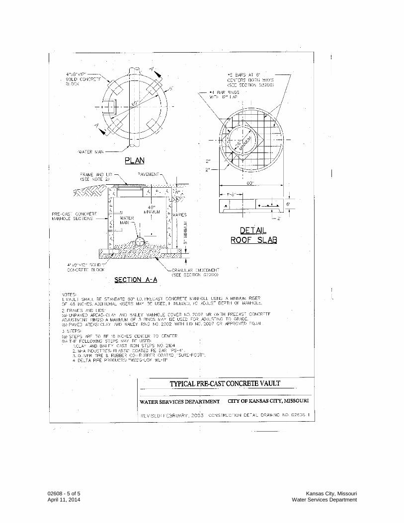
02608 - 5 of 5 Kansas City, Missouri April 11, 2014 Water Services Department
02618 - 1 of 11 Kansas City, Missouri January 29, 2016 Water Services Department
SECTION 02618
DUCTILE IRON PIPE WATER MAIN PART 1 GENERAL 1.1 Section Description
A. This section provides for pipe, fittings, and appurtenances associated with the installation of ductile iron pipe water main. This section applies to all water main 16" diameter and smaller and to other sizes when ductile iron pipe is selected.
1.2 Section Includes
A. Pipe B. Fittings C. Appurtenances D. Shop Coating and Lining E. Bolts and Nuts F. Protective Coatings
1.3 Related Sections
A. Section 01000 – General Requirements B. Section 01016 – Water Mains Near Sewers C. Section 01300 – Submittals D. Section 01600 – Material and Equipment E. Section 02200 – Excavation and Trenching F. Section 02575 – Surface Restoration G. Section 02608 – Concrete Vaults H. Section 02641 – Valves I. Section 02645 – Hydrants, Blowoffs and Flushing Assemblies J. Section 02669 – Thrust Restraints K. Section 02675 – Water Main Testing, Disinfection and Dechlorination
02618 - 2 of 11 Kansas City, Missouri January 29, 2016 Water Services Department
1.4 References
A. ANSI/NSF61 - Drinking Water Treatment Chemicals. B. ASTM A53 - Standard Specification for Pipe, Steel, Black and Hot-Dipped, Zinc
Coated, Welded and Seamless. C. ASTM A307 - Standard Specification for Carbon Steel Bolts and Studs, 60,000 psi
Tensile. D. ASTM D4976 - Standard Specification for Polyethylene Tubing. E. AWWA C104/ANSI A21.4 - Cement-Mortar Lining for Cast-Iron Pipe and Fittings. F. AWWA C105/ANSI A21.5 - Polyethylene Encasement For Ductile Iron Piping. G. AWWA C110/ANSI A21.10 - Gray-Iron and Ductile Iron Fittings. H. AWWA C111/ANSI A21.11 - Rubber-Gasket Joints for Cast Iron and Ductile Iron
Pressure Pipe and Fittings. I. AWWA C115/ANSI A21.15 - Flanged Ductile-Iron Pipe with Ductile Iron or Gray Iron
Thread. J. AWWA C150/ANSI A21.50 - Standard for the Thickness Design of Ductile Iron Pipe. K. AWWA C151/ANSI A21.51 - Ductile Iron Pipe Centrifugally Cast for Water. L. AWWA C153/ANSI A21.53 - Ductile-Iron Compact Fittings, 3 in. through 24 in.
M. AWWA C203 - Standards for Steel Pipe.
N. AWWA C550 - Protective Epoxy Interior Coatings for Valves and Hydrants. O. AWWA C600 - Installation of Ductile Iron Water Mains and their
Appurtenances. 1.5 Submittals
A. Follow the procedures for submittals provided in Section 01300 - Submittals B. Submit shop drawings and project data (laying schedule) for piping work showing
pipe and fitting sizes, valve locations, joint details; and hydrant locations. 1.6 Quality Assurance
A. Follow provisions of AWWA C600. B. The manufacturer shall be a company specializing in manufacturing the Products
specified in this section with minimum three years documented experience.
02618 - 3 of 11 Kansas City, Missouri January 29, 2016 Water Services Department
C. Mark rejected or defective materials and remove them from the work site.
1.7 Delivery, Storage, and Handling
A. Follow the provisions for the delivery, storage, protection and handling products to and at site provided in Section 01600 - Material and Equipment.
B. Accept piping on site. Inspect for damage and inventory.
PART 2 PRODUCTS 2.1 Water Main Pipe Materials
A. Pipe
1. Unless indicated otherwise, all 4” diameter through 12" diameter shall be thickness class 52. Pipe 16-inch diameter and larger shall be thickness Class 54 minimum. The pipe shall be designed in accordance with AWWA C150-ANSI A21.50 and manufactured per AWWA C151-ANSI A21.51 complete with all accessories.
2. All ductile iron pipe, and all fittings, valves, and other buried appurtenances,
shall be encased in polyethylene. 3. Joints: The joints shall be of the push-on type unless otherwise specified
conforming to ANSI/AWWA C111/A21.11, except gaskets shall be neoprene or synthetic rubber. Gaskets shall be certified as suitable for chlorinated potable water in accordance with ANSI/NSF61. Natural rubber will not be acceptable.
4. Restrained Joints: See Section 02669.
B. Fittings
1. All fittings shall be made of Ductile Iron and manufactured according to AWWA
C110/ANSI A21.10 or AWWA C153/ANSI A21.53. 2. Fitting joints shall be Mechanical Joint (MJ), Flange Joint (FLG), or Push-On
Joint, per AWWA C111/ANSI A21.11. All MJ glands shall be ductile iron. Fittings shall have distinctly cast upon them, the pressure rating and the letters “DI” or “Ductile”. FLG Fittings shall be used only for aboveground installations.
3. Flanged Joints: Shall be provided with full-face gaskets and shall meet the
requirements of AWWA C115/ANSI A21.15.
C. Appurtenances
1. Welded - On Outlets: May not be used in lieu of tees. 2. Tapping Sleeves:
02618 - 4 of 11 Kansas City, Missouri January 29, 2016 Water Services Department
a. Material: All material in the body, lugs, outlet, flange, bridge plate, bolts, nuts and washers shall be ASTM A-276 Type 304 or Type 316 or ASTM A-564 Type 630 stainless steel.
b. Body: Shall be a minimum of 14 gauge stainless steel and shall fit cast iron pipe classes A, B, C, and D.
c. Outlet: Shall be a minimum of 14-gauge stainless steel. The branch outlet shall be supplied with a tap and plug to permit pressure testing the sleeve prior to tapping the main.
d. Flange: Shall conform to AWWA C207 Class D with drilling in accordance with ANSI B 16.1 class 125, and shall be indexed per MSS-SP 60 to accept tapping valve.
e. Welding: All welding on the coupling shall be done with stainless steel rods.
f. Gaskets: Sleeve gaskets shall be full circumferential a minimum of ¼” thick gridded with tapered lap joint ends and stainless steel bridge plates molded flush into the gasket.
g. The Outlet: The outlet flange face shall be supplied with a bonded, full-face gasket. All gaskets shall be grade 30 specially compounded rubber, synthetic rubber, or 100 percent neoprene that shall have the necessary qualities to allow outside storage, permanence, and resistance to set after installation.
h. Bolts and Nuts: All bolts, nuts and washers shall be loose; lifter bar style bolt attachments shall not be permitted. All bolts and/or nuts shall be impregnated or coated to prevent seizure. Minimum diameter shall be 5/8”.
i. Working Pressure: Sleeve shall be designed for a minimum working pressure of 175 psi.
j. General: Power Seal Model 3490-AS; JMC 432; Cascade CST-Ex stainless steel extra heavy duty; Ford Model FTSS; Romac STD Band SST-III; Smith Blair Type 665.
k. Power Seal Model 3490MJ or approved equal may also be used. 3. Tie Rods: ASTM A276, Type 304 or Type 316 Stainless Steel. 4. Couplings: Dresser “Style 38” or Smith-Blair “441 or 411 Flexible Coupling”;
without pipe stop. Bolted compression type couplings shall be manufactured of steel or ductile iron specifically for use with ductile iron pipe.
D. Shop Coating and Lining
1. All pipe and fittings shall be cement mortar lined in accordance with AWWA
C104/ANSI A21.4. Asphaltic coating is not allowed. Any pipe or fittings above ground shall be prime coated with 6 mils DFT of Tnemec 140-1211 Epoxy Primer.
2. As an alternative to cement mortar lining on fittings, the manufacturer may use
a Fusion Bonded Epoxy on both the interior and exterior that complies with AWWA C550 and is NSF 61 approved for potable water.
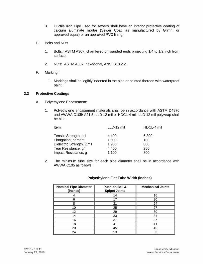
02618 - 5 of 11 Kansas City, Missouri January 29, 2016 Water Services Department
3. Ductile Iron Pipe used for sewers shall have an interior protective coating of calcium aluminate mortar (Sewer Coat, as manufactured by Griffin, or approved equal) or an approved PVC lining.
E. Bolts and Nuts
1. Bolts: ASTM A307, chamfered or rounded ends projecting 1/4 to 1/2 inch from
surface. 2. Nuts: ASTM A307, hexagonal, ANSI B18.2.2.
F. Marking:
1. Markings shall be legibly indented in the pipe or painted thereon with waterproof
paint. 2.2 Protective Coatings
A. Polyethylene Encasement:
1. Polyethylene encasement materials shall be in accordance with ASTM D4976 and AWWA C105/ A21.5; LLD-12 mil or HDCL-4 mil. LLD-12 mil polywrap shall be blue.
Item LLD-12 mil HDCL-4 mil Tensile Strength, psi 4,400 6,300 Elongation, percent 1,000 100 Dielectric Strength, v/mil 1,900 800 Tear Resistance, g/f 4,400 250 Impact Resistance, g 1,100 800
2. The minimum tube size for each pipe diameter shall be in accordance with AWWA C105 as follows:
Polyethylene Flat Tube Width (inches)
Nominal Pipe Diameter (inches)
Push-on Bell & Spigot Joints
Mechanical Joints
4 14 16 6 17 20 8 21 24 10 25 27 12 29 30 14 33 34 16 37 37 18 41 41 20 45 45 24 53 53
02618 - 6 of 11 Kansas City, Missouri January 29, 2016 Water Services Department
3. Adhesive tape shall be a general purpose adhesive tape 1-inch wide and approximately 8 mils thick, such as Scotch Tape No. 50, Polyken No. 900, Tapecoat CT or approved equal (Duct Tape will not be allowed).
B. Exterior Surfaces Underground (Excluding Pipe & Fittings): All metal surfaces,
including each mechanical coupling, shall be thoroughly cleaned and then coated with Tnemec coal-tar epoxy “High-Build Tnemec-Tar”. All material and the application thereof shall conform to AWWA C203.
C. Above ground pipe and fittings shall be field coated with Tnemec Coal Tar Epoxy
“High-Build Tnemec-Tar.” PART 3 EXECUTION 3.1 Handling
A. Pipe, fittings, and accessories shall be handled in a manner that will ensure installation in a sound, undamaged condition. Equipment, tools, and methods used in unloading, reloading, hauling, and laying pipe and fittings shall be such that the pipe, pipe coating, and fittings are not damaged. Hooks shall not be used. Under no circumstances shall pipe or accessories be dropped or dumped. Pipe and fittings shall not be moved by inserting anything into pipe ends.
B. Pipe and fittings on which the cement lining has been broken or loosened shall be
replaced. Where the damaged areas are small and readily accessible, the lining may be permitted to be repaired in accordance with AWWA C104.
3.2 Inspection
A. Pipe and fittings shall be carefully examined for cracks and other defects immediately before installation. Spigot ends shall be examined with particular care since they are vulnerable to damage from handling. All defective, damaged, or unsound pipe and fittings shall be rejected and marked as such and removed from the site of the work.
3.3 Preparation A. Cutting Pipe:
1. Ductile iron pipe shall be cut with a saw or an abrasive wheel. Existing cast iron pipe shall be cut with a saw or abrasive wheel.
2. The cutting of pipe with a torch will not be permitted. 3. Cutting shall be done in a neat manner without damage to the pipe or the
cement lining. Cuts shall be smooth, straight, and at right angles to the pipe axis. After cutting, the end of the pipe shall be dressed with a file to remove all roughness and sharp corners.
B. Cleaning:
02618 - 7 of 11 Kansas City, Missouri January 29, 2016 Water Services Department
1. The interior of all pipe and fittings shall be thoroughly cleaned of foreign matter before being installed and shall be kept clean until the work has been accepted.
2. Surfaces shall be wire brushed, if necessary, wiped clean, and kept clean until
jointing is completed. 3.4 Installation
A. General
1. Alignment: Runs intended to be straight shall be laid straight. Deflections from a straight line or grade shall not exceed the quantities stipulated in Table 4 or Table 5 of AWWA C600. Shorter pipe sections or special bends shall be installed where the alignment or grade requires them.
2. Laying Pipe: Pipe shall be protected from lateral displacement by pipe
embedment material installed as specified in Section 02200. Under no circumstances shall the pipe be laid in water; and no pipe shall be laid in unsuitable trench conditions.
a. Pipe shall be laid with the bell ends facing the direction of laying except
when reverse laying is specifically authorized by the CITY.
b. Whenever pipe laying is stopped, the open end of the line shall be sealed with a watertight plug that will prevent water and objects from entering the pipe.
3. No pipe length less than 18” shall be used.
B. Mechanical Joints:
1. The gasket and gland shall, after proper joint cleaning, be in position on the
spigot before shoving the pipe to its final position. Center the entering spigot so that the gland or follower ring is parallel to the face of the connecting bell. Joint shall be shoved "home" and the gland properly positioned with respect to the connecting bell with the connecting pipes in as nearly perfect alignment as practicable. The bolts shall be slightly and uniformly tightened. Deflection may be made after the bolts are tightened.
2. Coat the gasket with a lubricant (suitable for potable water) supplied by the pipe
manufacturer and all surfaces of the bell, spigot, and gland that will come in contact with the gasket at any time during assembly.
3. Gasket shall be carefully pushed into position and evenly seated in the bell. The
gland shall be shoved into place against the gasket, the bolts inserted, and the nuts tightened with the fingers until snug. Final tightening of the bolts shall be done with a ratchet torque wrench.
4. Partially tighten the bottom bolt, then the top bolts, alternately either side, and
finally the remaining bolts, alternately tightening bolts 180 degrees apart. This
02618 - 8 of 11 Kansas City, Missouri January 29, 2016 Water Services Department
cycle is then to be repeated until all bolts are tightened to the torque specified by the manufacturer:
5/8” bolts --- 40 to 60 foot pounds 3/4” bolts --- 60 to 90 foot pounds
5. If sealing is not maintained at the torque specified, the joint shall be
disassembled, thoroughly cleaned, and reassembled. Overstressing of bolts to compensate for poor installation practice will not be permitted.
C. Push-On Joints:
1. Wipe the gasket seat clean with a cloth and position in place. Coat the gasket
with a lubricant supplied by the pipe manufacturer. Apply to all of the inner surface of the gasket that will come into contact with the entering pipe.
2. Clean the plain end of the pipe and apply a thin film of lubricant (suitable for
potable water) to the outside of the plain end of the pipe and its beveled edge. Align the plain end of the pipe with the bell of the pipe to which it is to be joined. The joint deflection angle should not exceed the recommended maximum of the manufacturer.
3. Bring the plain end of the pipe in contact with the gasket and exert sufficient
force on the entering pipe so that its plain end compresses the gasket and makes contact with the base of the socket of the bell. This force can be applied by means of a jack type tool, backhoe, or other methods approved by the CITY.
D. Flanged Joints:
1. When bolting, care shall be taken to provide uniform gasket compression and
prevent unnecessary stress on the flanges. Flange shall be free to move in any direction while the flange bolts are being tightened. Bolts shall be tightened gradually and at a uniform rate to provide uniform gasket compression.
2. Use full-face gaskets only.
E. Restrained Joints:
1. Restrained joints shall be installed in accordance with the pipe
manufacturer’s recommendations. 2. All joints within utility casings shall be restrained joints.
F. Encasement:
1. Polyethylene encasement shall be installed on all ductile iron pipe and
fittings. The polyethylene shall prevent contact between the pipe, fittings, and the surrounding embedment.
02618 - 9 of 11 Kansas City, Missouri January 29, 2016 Water Services Department
2. The polyethylene encasement shall be installed as specified in "Method A" below and as shown on the Construction Detail Drawing No. 02618-1.
a. Method A: Polyethylene tubing shall be approximately two (2) feet longer
than the length of the pipe section to provide a one (1) foot overlap on each adjacent pipe section. Tube ends need not be taped in place unless directed by the CITY. Repair rips, punctures, or other damages to the polyethylene with adhesive tape or with a short length of polyethylene tube cut open, wrapped around the pipe, and secured with adhesive tape as directed by the CITY (duct tape is not allowed).
3. Pipe-Shaped Appurtenances: Bends, reducers, offsets, and other pipe-shaped
appurtenances shall be covered with polyethylene in the same manner as the pipe.
4. Odd-Shaped Appurtenances: Valves, tees, crosses, and other odd-shaped
pieces that cannot practically be wrapped in a tube shall be wrapped with a flat sheet or split length of polyethylene tube. The sheet shall be passed under the appurtenance and brought up around the body. Seams shall be made by bringing the edges together, folding over twice, and taping down. Tape polyethylene securely in place at overlaps, valve tops and all other penetrations.
5. Lifting devices shall not be placed over polyethylene. 6. Polyethylene shall be protected from exposure to weather or damage at all
times. 7. Openings in Encasement: Openings for branches, service taps, blow-offs, air
valves, and similar appurtenances shall be made by making an x-shaped cut in the polyethylene and temporarily folding the film back. After the appurtenance is installed, tape the slack securely to the appurtenance and repair the cut as well as any other damaged areas in the polyethylene with tape. The new appurtenance shall be wrapped.
8. Junctions Between Wrapped and Unwrapped Pipe: Where polyethylene
wrapped pipe joins an existing pipe which is not wrapped, extend the polyethylene tube to cover the unwrapped pipe a distance of at least three feet. Secure the end with circumferential turns of tape.
9. Taps: Wrap 3 layers of adhesive tape over the polyethylene, covering the area
where the tapping machine will be mounted. Mount the machine over the tape. Make the tap and install the corporation stop through the tape and polyethylene. After making the service connection, inspect the polyethylene, and repair damaged areas with tape.
3.5 Water Main and Sewer Separation
A. Refer to Section 01016.
02618 - 10 of 11 Kansas City, Missouri January 29, 2016 Water Services Department
3.6 Appurtenances
A. Concrete Vaults: Refer to Section 02608 B. Valves: Refer to Section 02641 C. Hydrants, Blow-off, and Flushing Assemblies: Refer to Section 02645 D. Thrust Restraints: Refer to Section 02669
END OF SECTION
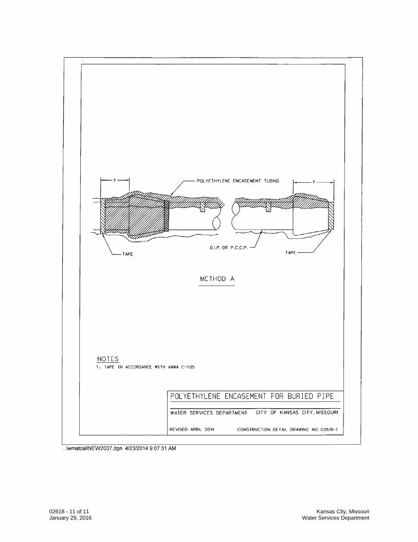
02618 - 11 of 11 Kansas City, Missouri January 29, 2016 Water Services Department
02641 - 1 of 17 Kansas City, Missouri July 21, 2014 Water Services Department
SECTION 02641
VALVES PART 1 GENERAL 1.1 Section Description
A. This section provides for the installation of required valves. 1.2 Section Includes
A. Gate Valves
B. Butterfly Valves
C. Air Release Valves
D. Tapping Valves
E. Valve Boxes, Bases, Lids and Covers, Torque Limiting Devices
F. Valve Seals and Coatings G. Check Valves
1.3 Related Sections
A. Section 01300 – Submittals B. Section 01600 – Material and Equipment C. Section 02608 – Concrete Vaults D. Section 02618 – Ductile Iron Pipe Water Main
E. Section 02669 – Thrust Restraints
1.4 References
A. ANSI B16.1 - Pipe Flanges and Flanged Fittings, Cast-Iron B. ANSI/AWWA C110/A21.10 - Ductile-Iron and Gray-Iron Fittings. C. ANSI/AWWA C111/A21.11 - Rubber-Gasket Joints for Ductile-Iron Pressure Pipe
and Fittings. D. AWWA C504 - Rubber-Seated Butterfly Valves.
02641 - 2 of 17 Kansas City, Missouri July 21, 2014 Water Services Department
E. AWWA C509-94 - Standard Specification for Resilient Seated Gate Valves for Water Supply Service.
F. AWWA C512-99 - Air Release, Air/Vacuum, and Combination Air Valves for Water
Works Service. G. ASTM A48 - Standard Specifications for Gray-Iron Castings. H. ASTM A126 - Standard Specifications for Gray-Iron Castings for Valves, Flanges,
and Pipe Fittings. I. ASTM A276 - Standard Specification for Stainless Steel Bars and Shapes. J. ASTM A536 - Standard Specification for Ductile Iron Castings. K. ASTM A564 - Standard Specification for Hot-Rolled and Cold-Finished Stainless
Steel Bars and Shapes. L. ASTM D471 - Standard Test Method for Rubber Property-Effect of Liquids. M. ASTM D1149 - Standard Test Method for Rubber Deterioration-Surface Ozone
Cracking in a Chamber. N. C508: Swing-Check Valves for Waterworks Service, 2 in. through 24 in.
1.5 Submittals
A. Follow the procedures for submittals provided in Section 01300 - Submittals B. Shop Drawings: Detailed drawings, data and descriptive literature on all valves and
appurtenances, including:
1. Manufacturer 2. Dimensions 3. Size 4. Materials of construction 5. Weight 6. Protective coating 7. Actuator weight and turns to operate where applicable 8. Calculations for actuator torque where applicable 9. Proof of design tests in accordance with Sec. 5.2.4. AWWA C504 10. Cross section drawings detailing all components
02641 - 3 of 17 Kansas City, Missouri July 21, 2014 Water Services Department
C. The Contractor shall submit descriptive literature describing the proposed valves and
accessories. Contractor shall also furnish a copy of the manufacturer’s warranty that applies to the valves and actuators.
1.6 Quality Assurance
A. Valves shall be manufactured by a company specializing in the regular production of the Products specified herein and proven reliable in similar service for at least five (5) years.
B. Insofar as possible, all valves of the same specific type shall be the product of one
(1) manufacturer. 1.7 Delivery, Storage and Handling
A. Follow the provisions for the delivery, storage, protection and handling Products to and at site provided in Section 01600 - Material and Equipment.
PART 2 PRODUCTS 2.1 General
A. Marking and identification of valves shall conform to AWWA C504 or AWWA C509. 2.2 Gate Valves
A. Gate Valves: Except as modified or provided herein, all gate valves shall be 200 psi, ductile iron body, resilient-seated, tight closure gate valves with non-rising stems conforming to the requirements of AWWA C509. Thin wall valves are prohibited.
B. Valve Ends:
1. Mechanical Joint or Push On Joint: Conforming to ANSI/AWWA C111/A21.11
except where flange ends are required. All glands shall be ductile iron. 2. Flanged: Conforming to the dimensions and drilling of ANSI B16.1 for cast iron
flanges and flange fittings, Class 125. The laying lengths of the flange valves shall conform to the dimensions of ANSI B16.1.
C. Valve Gate: Wedge type gate with a minimum 3/8 inch thick resilient rubber,
urethane rubber, Buna “N” or SBR rubber bonded to or mechanically attached to one side or both sides of the gate. No sliding or shear is permitted on the resilient seat, when compressed to a drop-tight shut-off.
D. Stainless Steel Bolts and Nuts: The bolts and nuts that fasten the bonnet to the valve
body, the actuator nut to the valve, and the bonnet thrust plate to the bonnet shall be AISI Type 304 or 316 stainless steel.
02641 - 4 of 17 Kansas City, Missouri July 21, 2014 Water Services Department
E. Seals: Gate Valves shall be provided with stem seals of the “O” ring type. Two “O” rings shall be used with at least one “O” ring inserted above the thrust collar. The packing plate shall be attached to the valve bonnet by not less than two (2) bolts if bolts are required and one “O” ring below the thrust collar.
F. Coatings: All exterior surfaces of each valve shall be cleaned and painted in the
shop with two (2) coats of asphalt varnish conforming to Federal Specifications TT-V-51-E. The interior surface shall have a protective coating of fusion-bonded, non-toxic epoxy that is safe for potable water. Non-toxic epoxy may also be used for exterior coating
G. Tapping Valves: The valves shall be 200 psi, ductile iron body, resilient-seated, tight
closure gate valves with non-rising stems in conformance with ANSI/AWWA C509, except that the outlet end shall be a standard mechanical joint end conforming to ANSI/AWWA C111/A21.11 and the inlet end shall have an inlet flange conforming to ANSI B16.1 for cast iron flanges, Class 125. Gland shall be ductile iron. Approved mechanical joint valves shall be used with Power Seal Model 3490MJ tapping sleeves.
2.3 Butterfly Valves
A. General: These specifications provide for the purchase and installation of ductile iron, vault installation or direct bury, rubber-seated, tight closure in both directions, 16 fps butterfly valves and actuators in sizes from 16-inch through 90-inch diameter. All valves shall be Short-Body Flanged-end valves for use in vaults or Mechanical-Joint-end valves for direct bury. The valves and actuators shall be of the latest model with all standard accessories ordinarily furnished to the industry except as otherwise specified herein. All valves of one size shall be built by one manufacturer with actuators built by one manufacturer. The latest revision of AWWA C504, Standard for Rubber Seated Butterfly Valves, shall govern unless noted otherwise herein. The intent of all provisions of AWWA C504 shall apply equally to valves larger than 48" diameter and to 250 psi valves unless noted otherwise herein. Each valve shall have a unique serial number, which shall be part of the information on the tag specified in paragraph 10.
B. Owner’s Data: The quantity, pressure rating, valve material type, and sizes shall be as indicated on the drawings. Each valve shall be fastened to and delivered on an individual pallet on 4” x 4”, or heavier, wood skids, high enough to protect the valve and actuator. All other requirements of AWWA C504 Section 6.2 "Shipping" shall apply. Delivery shall be to the jobsite.
C. Descriptive Literature: The Bidder shall include literature describing the valves and
actuators to be furnished. D. Warranty: The Supplier shall furnish three copies of the warranty that applies to the
valves and actuators they propose to furnish. The warranty period shall be for a minimum of three years after substantial completion of the contract under which the valve is installed or twenty years from the date of shipment, whichever comes first.
E. Shop Drawings: The approved Supplier, ONLY, before manufacturing the valves and
actuators, shall submit eight (3) sets of certified shop drawings, parts lists, exploded
02641 - 5 of 17 Kansas City, Missouri July 21, 2014 Water Services Department
assembly drawings, and material specifications, for approval, to the WSD. In addition to the above, the supplier shall furnish certified copies of proof-of-design tests performed in accordance with Section 5.2.4 of AWWA C504.
F. Design: All valve parts shall be designed for a minimum safety factor of 3, based on
yield strength, or 5, based on tensile strength. G. Flow Coefficient “K”: The flow coefficient in terms of velocity head (K), in the full open
position, shall not be greater than the following:
75 psi 150 psi 250 psi
16 inch thru 24 inch K=0.40 K=0.45 K=0.55 30 inch thru 48 inch K=0.40 K=0.40 K=0.50 54 inch thru 72 inch K=0.40 K=0.40 ------ 78 inch thru 90 inch K=0.40 ------ ------
Pressure measurements shall be made at two pipe diameters upstream of the valve and eight pipe diameters downstream of the valve in accordance with recommended procedures of ASME Report on Fluid Meters, Latest Edition.
H. Minimum Port Diameter: The minimum port diameter through the valve shall not be
less than as listed below: Nominal Size Allowable Difference in Diameter 16-inch - 42 inch 1 inch 48-inch - 54-inch 1 1/4-inch 60-inch - 72-inch 1 1/2-inch 78-inch - 90-inch 3 inch
I. Fasteners: All bolts and nuts inside and outside the valve, except Mechanical Joint bolts and nuts, shall be ASTM A276 Type 304 or Type 316 stainless steel or ASTM A564 Grade 630 stainless steel.
J. Valve Body: The valve body shall be ductile iron poured to full gray iron thickness.
The position of the valve seat in the valve body shall be marked on the outside of the valve body, within 12 inches of the actuator nut of upper valve trunion, tagged or cast, in 1/4” high print, “SEAT THIS SIDE.” Tags shall be ASTM A276 Type 304 or Type 316 stainless steel.
K. End Plate: No bolt or end thrust adjusting screw shall extend through the End Plate.
L. End Connections: The dimensions and drillings of end flanges shall conform to ANSI
B16.1 for 75 psi valves, ANSI B16.1 Table 5 for 150 psi valve and 250 psi valves, both with 150 psi drillings. If specified in the invitation to bid, 250 psi dimensions and drillings of end flanges shall conform to ANSI B16.1 Table 8, to include but not be limited to, flange outside diameter, flange thickness, bolt circle diameter, bolt
02641 - 6 of 17 Kansas City, Missouri July 21, 2014 Water Services Department
diameter, and bolt quantity. The Mechanical Joint valves are to include the following accessories: gaskets, ductile iron gland rings, mechanical joint bolts, and nuts.
M. Shafts: All valve shafts shall be in accordance with AWWA C504 Table 3 unless
otherwise addended herein. All valve shafts, dowels, and taper pins shall be ASTM A276 Type 304 or Type 316 stainless steel or ASTM A564 Grade 630 condition H1100 stainless steel. The valve shaft shall have a means of clearly indicating the position of the disc on the actuator end of the shaft. This mark shall be machine grooved and shall be visible when the cover and lubrication are removed and shall be offset to the same side as the disc. The valve shaft shall be completely enclosed between the valve body and the actuator body.
N. Valve Disc: The valve disc shall be ductile iron and shall seat perpendicular to the
centerline axis of the valve body. O. Valve Seats: The resilient seat shall be EPDM synthetic rubber applied either to the
valve disc or valve body. The resilient seat shall be mechanically secured to either the valve disc or valve body with ASTM A276 Type 304 or Type 316 stainless steel fasteners or non-bonding epoxy. Resilient seats shall be field adjustable and replaceable without special tools or instruction.
Mating surfaces for the valve seats shall be ASTM A276 Type 304 or Type 316 stainless steel. All seats shall be designed to provide tight shut-off with flow in both directions.
P. Shaft Seals: Seal shall be provided by the use of standard V-type packing or standard “O” ring seals; pull-down packing is not acceptable. The valve shall be designed so that the actuator may be removed and replaced while the valve is in service without losing water.
Q. Actuator: The actuator shall be Limitorque Model HBC series or Auma Model GS series (additional spur gear reduction gear boxes may be necessary to achieve minimum “number of turns” requirement) or those that have received written approval after May 1, 2002 from the Water Services Department. The actuator shall be a link lever traveling nut type, worm gear type, or yoke and nut type and shall be capable of withstanding submersion in water to a pressure of 10 psi. All exposed bolts, nuts, and shafts shall be of ASTM A276 Type 304 or Type 316 stainless steel or ASTM A564 Grade 630 condition 1100 stainless steel. All actuators must have outside mechanical adjustments capable of adjusting valve travel without removing the valve from the pipeline or removing the actuator cover.
Buried service valves shall open right (clockwise). The actuator shall be equipped with a two-inch square AWWA ductile iron nut having a flanged base upon which shall be cast the word OPEN and an arrow indicating the direction to open. The nut shall be securely pinned to the actuator shaft using a stainless steel fastener.
Vault service valves shall open left (counter-clockwise). The actuator shall be supplied with a handwheel. The handwheel shall be no smaller in diameter than 30 inches and no larger in diameter than 36 inches. Manual actuators shall be suitable for future adaptation to motor operation. Vault service actuators shall have an
02641 - 7 of 17 Kansas City, Missouri July 21, 2014 Water Services Department
indicator on the exterior of the actuator indicating the valve disc position. This indicator shall be stainless steel.
All gearing and actuator stops shall be enclosed in a suitable housing with a removable cover to permit inspection, repair, and adjustment of the mechanism. Adjustable stop limiting devices shall be provided inside the actuator housing to stop the input shaft at full open and full closed positions. The use of stop nuts or shaft collars which rely on clamping forces or set screws to prevent rotation of the nut or collar on the screw shaft will not be acceptable. The actuator shall rotate the disc from full open to full closed and vice-versa using not less than, nor more than, the number of turns indicated below:
Valve Size Minimum Maximum (Inches) Turns Turns 16 30 60 20 40 80 24 40 80 30 40 200 36 80 200 42 80 220 48 90 300 54 90 700 60 200 700 72 200 700 90 200 700 The number of turns shall be included in the information on the tag specified in paragraph 10.
R. Painting Interior of Valves: The interior of valves sizes 16-inch through 48-inch shall
be coated with a white, NSF 61 certified, fusion-bonded or powder coated epoxy. The interior of valve sizes 54-inch through 90-inch shall be coated with a white epoxy paint, Tnemec N141 NSF 61 or approved equal. Surface preparation and application shall be in accordance with SSPC PA-1. The dry film thickness of the coating shall be a minimum of 10 mils. A painting Affidavit of Compliance shall be submitted in accordance with paragraph 21 and AWWA C550 NSF 61 and shall be free of holidays.
S. Painting Exterior of Valves: The exterior of valve sizes 16-inch through 48-inch shall be coated with an NSF 61 certified, fusion-bonded or powder coated epoxy. The exterior of valve sizes 54-inch through 90-inch shall be coated with an epoxy paint, Tnemec N141 NSF 61 or approved equal. Surface preparation and application shall be in accordance with SSPC PA-1. The dry film thickness of the coating shall be a minimum of 10 mils. A painting Affidavit of Compliance shall be submitted in
02641 - 8 of 17 Kansas City, Missouri July 21, 2014 Water Services Department
accordance with paragraph 21 and AWWA C550 NSF 61 and shall be free of holidays.
T. Factory Inspection: The Water Services Department’s inspector will witness leakage
and hydrostatic tests at the Manufacturer's facility and will inspect all valves for conformance to the specifications. The Manufacturer shall include in the bid all expenses for transportation, lodging, and meals required by the Department's inspector to complete the inspection. Absolutely no expenses are to be paid by the inspector at any time.
After the valves are delivered, the Water Services Department may again test the valves and actuators for compliance with the specifications. The valves that do not meet specification will be shipped back to the manufacturer for modifications, at the Manufacturer's expense. The manufacturer shall also be responsible for all testing expenses incurred by the Department if the valve fails to perform as specified herein.
U. Tests: All test data per AWWA C504 sections 3.8.5.8, 3.8.5.9, 4.5.8.1, 4.5.8.3,
4.5.8.5.2, 5.2.1, 5.2.2, 5.2.3, and 5.2.4 shall be submitted in triplicate to the WSD.
V. Affidavit of Compliance: The manufacturer shall send an affidavit of compliance, in triplicate, to the WSD.
W. Torque Limiting Devices: Contractor shall provide a Torque Limiting Device for each
direct-bury butterfly valve as specified herein.
1. The torque limiting device shall make over-torque, in either direction, impossible. The unit shall be preset and designed to release when the torque level exceeds 210 foot pounds on the operating nut, in either direction, OPENING or CLOSING the valve. The torque unit shall reset automatically when the torque level drops below 200 foot pounds on the operating nut in either direction.
2. The torque level of the unit shall be adjustable so it may be field set to release at a desired torque limit.
3. The device shall be model D86 Overtorque Protector, manufactured by
Aunspach Controls Co, Inc. or approved equal.
4. The unit shall be less than 5-1/4 inches in diameter and made to mount on the valve inside of the 6-inch diameter stem riser tube of the valve box or in the valve box.
5. The unit shall be provided with a two-inch A.W.W.A. operating nut, securely
attached to the device. The nut shall have an arrow on the base indicating the valve opens to the “RIGHT” (clockwise) and the word “OPEN”. The unit shall be provided with a two-inch square tapered A.W.W.A. socket securely attached to the device. The socket shall fit a 2-inch A.W.W.A. nut.
6. The unit shall be designed to withstand submersion in water to a pressure of
10 psi; to endure long periods (years) of active or inactive use buried underground and submerged in water. The unit shall be sealed to prevent
02641 - 9 of 17 Kansas City, Missouri July 21, 2014 Water Services Department
water and direct from entering the mechanism. The unit shall be packed with a suitable grease.
7. All housing parts, including nut and socket, shall be coated inside and outside
with catalyzed (2-part) epoxy. A top coat of catalyzed (2-part) polyurethane enamel shall be applied over the epoxy for additional hardness and extra corrosion protection.
8. Contractor shall mount the torque limiting device’s integral socket on each
butterfly valve’s 2-inch A.W.W.A. operating nut inside of the stem riser tube before backfilling around the valve. No fasteners or screws shall be used.
2.4 Air Release Valves
A. Air Release Valves and Vaults:
1. Air release assemblies shall be manufactured in accordance with AWWA C512. 2. Air release valve vaults and castings: Refer to Section 02608. 3. All piping shall be brass pipe except the air outlet from the air release valve that
shall be brass or copper tubing. Brass piping shall be ASTM B43, Extra Strong with ASME 816.1 Class 250 fittings.
B. Air Release Valves for mains 12-inches in diameter or smaller (3/4-inch Diameter):
1. Isolation valves shall be ¾-inch bronze ball valves, 150 psi working pressure. 2. The ¾-inch air release assembly shall be as manufactured by ARI Flow Control
Accessories, Model S-050 or an approved equal.
3. Air release valves shall be installed in accordance with Drawing No. 02641-1.
4. Provide vault cover with minimum one 1-inch dia. hole for air flow.
C. Air Releases for mains larger than 12-inches in diameter:
1. Each assembly shall have a two-inch inlet connection. 2. Isolation valves shall be 2 inch bronze ball valves with screwed, non-rising
stems, 175 psi working pressure.. 3. The 2” air release valve shall be an ARI Flow Control Accessories Combination
Air Release Valve, Model D-040 or approved equal.
4. Air release valves shall be installed in accordance with Drawing Nos. 02641-2 and 02641-2b.
5. Provide vault cover with a minimum four 1-inch dia. holes for air flow.
02641 - 10 of 17 Kansas City, Missouri July 21, 2014 Water Services Department
2.5 Valve Boxes, Bases, Lids and Covers
A. One-piece Valve Boxes and Bases:
1. One-piece valve boxes and bases shall be injection molded plastic conforming to ANSI/ASTM 2853, Class 1212 as manufactured by Ametek or approved equal.
B. Two-piece Valve Box and Base:
1. Valve Boxes: Boxes shall be 6" Class 52 DIP; or 6" Class 160 PVC pipe. Bases
are required on all valves. 2. Valves Bases: Valve bases shall be Clay & Bailey No. 2260-4 or an approved
equal.
C. Lids and Covers: Valve lids and covers shall be Clay & Bailey No. 2193, 2193NS or an approved equal. Valve lids shall have "Water" cast in the lid.
2.6 Check Valves
A. All check valves shall be Ken-Flex Resilient Hinge check valves as manufactured by Kennedy Valve Company or approved equal.
B. Check valves shall be ductile iron body with reinforced Buna-N rubber flapper. C. Check Valves shall be rated for 250 psi working pressure, 500 psi hydrostatic test for
structural soundness.
D. Check Valves shall have ANSI 16.1 – Class 125 flanged end connections. E. The check valve body shall have full flow equal to nominal pipe diameter at all points
in the valve. The valve body shall be of ductile iron construction to ASTM-A-536 – 65-45-12. Castings will be clean and sound without defects that will impair their service. No plugging or welding of such defects will be allowed. The seating surface will be at a 45 degree angle to minimize water hammer.
F. Rubber Clapper & Hinge shall be constructed of ductile iron to ASTM-A 536-65-45-
12. Both Clapper and hinge shall have permanently bonded Buna-N rubber with a metal reinforcement connecting the hinge to the clapper.
G. The top cover plate will be of ductile iron to ASTM-A536-65-45-12 & must be of full
size to allow removal of the disc without removing the valve from line. All exterior nuts and bolts shall be 304 or 316 stainless steel.
H. All iron parts inside and out will be fusion bonded epoxy coated. All coatings must be
NFS-61 approved for use in drinking water systems.
02641 - 11 of 17 Kansas City, Missouri July 21, 2014 Water Services Department
I. Vault service check valves shall have an external mechanical position indicator. PART 3 EXECUTION 3.1 Inspection
A. Each valve shall be inspected before installation to insure that all foreign substances have been removed from within the valve body, and shall be opened and closed to see that all parts are in required working condition.
3.2 Setting Valves
A. All valves and fittings shall be set and jointed in the manner specified herein. The valves shall be set vertical in the horizontal pipeline. All valves shall be anchored directly to adjacent tees or crosses.
B. One-piece valve box and base or a two-piece valve box and valve base shall be
installed on all valves. An approved valve box alignment device shall also be installed in all valve boxes.
C. Valve covers, bases, and lids shall be supported and maintained, centered and plumb
over the actuator nut. Cover shall be flush with the roadway or ground surface or at such other as directed by the WSD.
3.3 Appurtenances
A. Hydrants; Blowoff, and Flushing Assemblies: Refer to Section 02645 B. Concrete Vaults and Covers: Refer to Section 02608 C. Thrust Restraints: Refer to Section 02669
D. General
1. Certification: The manufacturer shall provide an affidavit in triplicate certifying
that the valves and actuators comply with the provisions of these Specifications.
E. Leak Tests: (for Butterfly Valves)
1. Each valve shall be shop tested in both directions for leaks in the closed position. The test shall be conducted with the body in a horizontal plane.
2. Air pressure shall be applied to the lower face of the disc for 5 minutes. 3. Both 150-psi and 250-psi rated valves shall be leak tested to 250-psi pressure. 4. The upper surface of the valve disc shall be visible and covered with a pool of
water at "O" psi pressure. There shall be no leakage past the valve disc. Bubbles will appear in the water on the disc if it is leaking.
02641 - 12 of 17 Kansas City, Missouri July 21, 2014 Water Services Department
5. The valve body shall be tested with an internal hydrostatic pressure equivalent to two times the specified shutoff pressure. There shall be no leakage, during the test, through the metal, the end joints, or the shaft seals; nor shall any part be permanently deformed.
6. The hydrostatic test period for 4-inch valve bodies through 20-inch bodies shall
be at least 3 minutes. Valve bodies 24-inch and larger shall be tested for at least 10 minutes.
F. Performance Tests:
1. Each valve shall be shop operated three times from full closed to full open
position, and reverse, under no flow condition to demonstrate that the complete assembly is workable.
2. Each valve should also be tested in the same manner following installation.
END OF SECTION
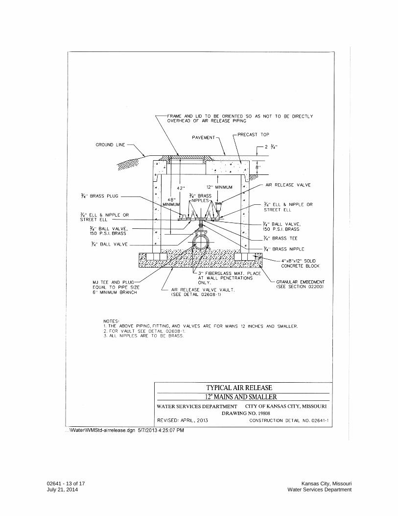
02641 - 13 of 17 Kansas City, Missouri July 21, 2014 Water Services Department
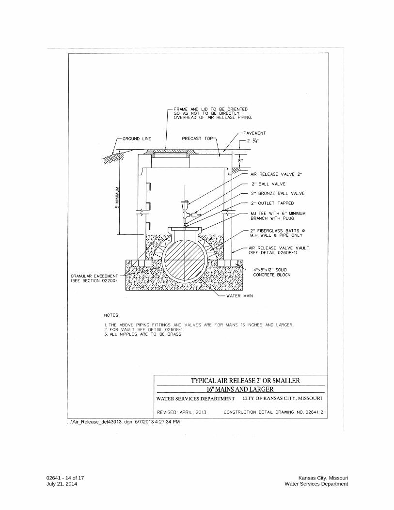
02641 - 14 of 17 Kansas City, Missouri July 21, 2014 Water Services Department
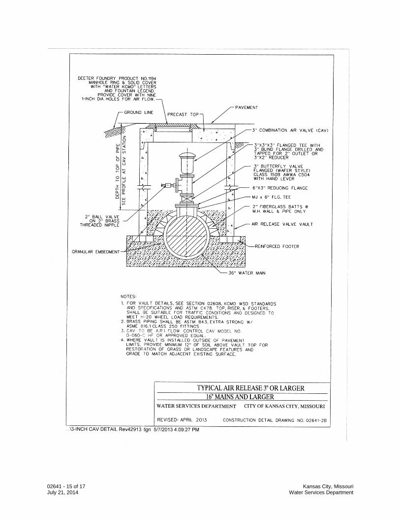
02641 - 15 of 17 Kansas City, Missouri July 21, 2014 Water Services Department
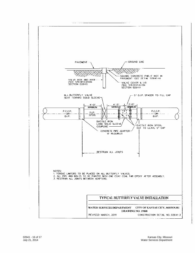
02641 - 16 of 17 Kansas City, Missouri July 21, 2014 Water Services Department
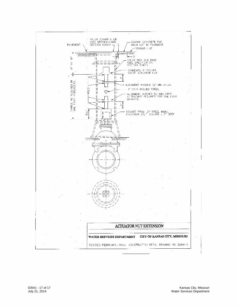
02641 - 17 of 17 Kansas City, Missouri July 21, 2014 Water Services Department
02645 - 1 of 10 Kansas City, Missouri April 14, 2014 Water Services Department
SECTION 02645
HYDRANTS, BLOWOFF AND FLUSHING ASSEMBLIES PART 1 GENERAL 1.1 Section Description
A. This section provides for the installation of hydrants, and blowoff and flushing assemblies.
1.2 Section Includes
A. Hydrants B. Blowoff and Flushing Assemblies
1.3 Related Sections
A. Section 01016 – Water Mains Near Sewers B. Section 01300 – Submittals C. Section 01600 – Material and Equipment D. Section 02575 – Surface Restoration E. Section 02200 – Excavation and Trenching F. Section 02618 – Ductile Iron Pipe Water Main
G. Section 02641 – Valves H. Section 02669 – Thrust Restraints I. Section 03001 – Concrete
1.4 Submittals
A. Follow the procedures for submittals provided in Section 01300 – Submittals. B. Product Data: Submit catalog cuts and dimension data.
1.5 Quality Assurance
A. The manufacturer shall be a company specializing in manufacturing the Products specified in this Section with minimum three years documented experience.
02645 - 2 of 10 Kansas City, Missouri April 14, 2014 Water Services Department
1.6 Delivery, Storage, and Handling
A. Follow the provisions for delivery, storage, protection, and handling Products to and at site provided in Section 01600 - Material and Equipment.
B. Accept units on site. Inspect for damage and inventory.
PART 2 PRODUCTS 2.1 Hydrants
A. General. Hydrants shall be current Kansas City, MO. pattern hydrants manufactured especially for CITY. All hydrants shall be designed and manufactured in strict compliance with AWWA C-502 entitled “A.W.W.A. Standard for Dry-Barrel Fire Hydrants” unless otherwise specified.
B. Approved hydrants. Only the following hydrants are approved.
Clow Medallion M&H Regent 129i Mueller Super Centurion 200 AVK QPL245 Nostalgic Style Fire Hydrant – Model 2760
1. No changes or modifications to the approved hydrant shall be made without
prior written notice and written approval.
C. Specifications. Hydrant bury will be measured from the bottom of the hydrant base to the bury line (finished grade line) and shall be five foot (5’) bury unless otherwise specified.
1. All hydrants shall be the traffic model type. Hydrants shall have one (1)
pumper nozzle located in the horizontal plane. The upper barrel and lower barrel shall be sealed by an EPDM rubber gasket or O-ring.
2. Hydrant base shall be provided with a mechanical joint inlet to accommodate
6-inch diameter ductile iron pipe, in accordance with A.N.S.I. A21.11 (AWWA Standard C-111, Rubber Gasket Joints for Cast Iron and Ductile Iron Pressure Pipe and Fittings”). The hydrant shall be supplied with necessary accessories for the mechanical joint.
3. Main valve of the hydrant shall be 5-1/4 inch diameter compression type, which
closes with water pressure.
4. The operating nut shall be a truncated pentagon, 1-1/2 inches on the bottom, 1-7/16 inches on the top, with a finished height of 1-1/8 inches (see attachment A). The bonnet shall be so constructed that the opening nut shall not travel during opening and closing the hydrant. The bonnet shall house a Viton gasket or O-ring seal between the opening nut and the bonnet to prevent moisture and foreign material from entering the lubricant reservoir.
02645 - 3 of 10 Kansas City, Missouri April 14, 2014 Water Services Department
The bonnet shall also house Viton gasket or O-ring seal between the bonnet and the upper stem to retain the lubricant in the reservoir.
5. The hydrant shall be supplied with a tamper resistant shield for the operating
nut. The shield shall be in accordance with the attached drawing, Attachment B.
6. The hydrant shall open by turning the operating nut to the right (in a clockwise
direction when viewing the hydrant from above).
7. The pumper nozzle threads shall be in accordance with the Federal Screw Thread Standard H28, Section 10, American National Hose Coupling and Fire Hose Coupling Threads. The pumper nozzle shall have right-hand threads and have a 4-inch nominal diameter with 4 (four) threads per inch. The nozzle threads shall be lightly greased from factory with a suitable food grade lubricant.
8. Nozzle cap shall be cast iron and shall be furnished with a synthetic rubber
installed in a retaining groove in the inside of the cap. The dimensions and shape of the nozzle cap nut shall be the same as the operating nut as described in Section 4 above, except with a finished height of 1-inch.
9. The exterior of the hydrant above the bury line, nozzle caps, and the bonnet
shall be powder coated with epoxy or Triglycidyl Isocyanurate (TGIC) polyester. If epoxy powder is used, it shall be top-coated with a UV resistant, high-gloss acrylic polyurethane paint. The barrel section of the hydrant shall be gloss International Orange. The bonnet section and nozzle caps shall be gloss Black. The exterior of the hydrant below the bury line shall be coated with an asphalt varnish with a film thickness of at least 10 mils.
10. All non-thread, non-machines interior surfaces of the hydrant base shall be coated with a wet-applied NSF 61 certified white potable epoxy (such as Tnemec 20-AA90) or powder coated with an NSF 61 certified white epoxy. The exterior of the hydrant base shall also be epoxy coated.
11. Hydrant extensions (spool pieces), if requested and approved by the Water
Services Department, shall be a complete assembly allowing for the hydrant’s height to be adjusted in six (6) inch increments. The assembly shall be furnished with instructions and all required accessories necessary to adjust the hydrant’s height and maintain the hydrant’s traffic feature. Hydrant extensions shall be International Orange in color and shall be coated in accordance with Section 9.
12. All external hardware shall be 304 or 316 stainless steel.
13. The lower hydrant stem from the break-away coupling to the main valve and
any attaching hardware securing the main valve assembly to the lower stem shall be 304 or 316 stainless steel. Any cross pins securing any part of the main valve assembly or break away stem coupler shall be 420 stainless steel.
02645 - 4 of 10 Kansas City, Missouri April 14, 2014 Water Services Department
The lower stem nut may be integral to the lower valve plate or main valve assembly.
14. Main valve assemblies shall be of either three-piece (upper valve plate, main
valve seat, lower valve plate) or one-piece EPDM encapsulated ductile iron design. The lower valve plate of three-piece design main valve assemblies shall be powder coated with an NSF 61 certified epoxy.
15. The upper surface of the seat ring shall have raised lugs allowing for positive
engagement of a hydrant disassembly tool. The raised lugs shall be of sufficient design to allow for the removal of the seat ring.
D. Shop Drawing. Prior to manufacturing the hydrants, the manufacture shall submit
three (3) sets of detailed shop drawings for written approval. E. Packaging. All hydrants shall be bundled in a group no larger than three (3)
hydrants wide by three (3) hydrants high. All hydrants shall be shipped with the hydrant base inlet pointing down. All hydrants shall be separated wood framing adequate to prevent the hydrants from touching the ground or each other. Binding the hydrants together shall be a band or wrap adequate to per handling of the hydrant bundles with a crane truck or a forklift. All hydrants shall be delivered with the hydrant nozzle cap installed.
F. Delivery. The Yard Store shall receive a notice of shipping at least 2 days prior to
shipping the hydrants. All hydrants shall be delivered to the Yard Store, 2409 E. 18th Street, Kansas City, Missouri, 64127. Before payment is made for any deliveries, Systems Engineering Division shall be notified and the shipment will be inspected by Systems Engineering Division or its designee for compliance with these specification.
2.2 Blowoff and Flushing Assemblies
A. Mechanical joint plug: Drilled and tapped for 2-inch standard pipe threads. B. Elbows and outlet pipe: standard weight galvanized pipe and fittings. C. All discharge piping shall have a 2” PVC cap on top. D. Blowoff Assembly:
PART 3 EXECUTION 3.1 Preparation
A. The areas around each hydrant valve shall be thoroughly compacted to prevent settlement of these areas.
B. The weep holes of the hydrant shall be kept clear and free to drain with 1-½ C.Y. of
coarse stone (3/4” clean minimum).
02645 - 5 of 10 Kansas City, Missouri April 14, 2014 Water Services Department
3.2 Installation
A. Hydrant shall stand plumb and when placed behind curbs, the centerline of the hydrant shall be at least twenty-four (24) inches from the back of the curb or 4’ from the edge of pavement when there is no curb. Hydrant shall not be set in a drainage ditch.
B. Hydrant shall be rotated so as to have the nozzle facing the street or rotated to face
any direction as required by the CITY. C. Hydrants are to be installed with mechanical joint anchoring fittings or approved
restraint devices. Refer to Section 02669.
D. Hydrants are to be installed in accordance with Details 02645-1, 02645-2, and 02645-3.
E. After installation and before hydrants are placed in service, Contractor shall field
apply two separate coats of all surface spray enamel paint, in accordance with paint manufacturers recommendations, to completely cover each hydrant dome in accordance with the following:
Hydrants connected to 12” or larger mains Krylon 5816 Green (or approved equal) Hydrants connected to mains smaller than 6” Krylon 5814 Red (or approved equal) Hydrants connected to 6” or larger mains, but smaller than 12” mains. Krylon 5812 Black (or approved equal)
This color-coding is intended to provide firefighters and other emergency workers a permanent, quick visual reference to indicate the size of water main connected to each hydrant.
F. Blow off and flushing assemblies are to be installed in accordance with Details
02645-4, 02645-5, and 02645-6.
END OF SECTION
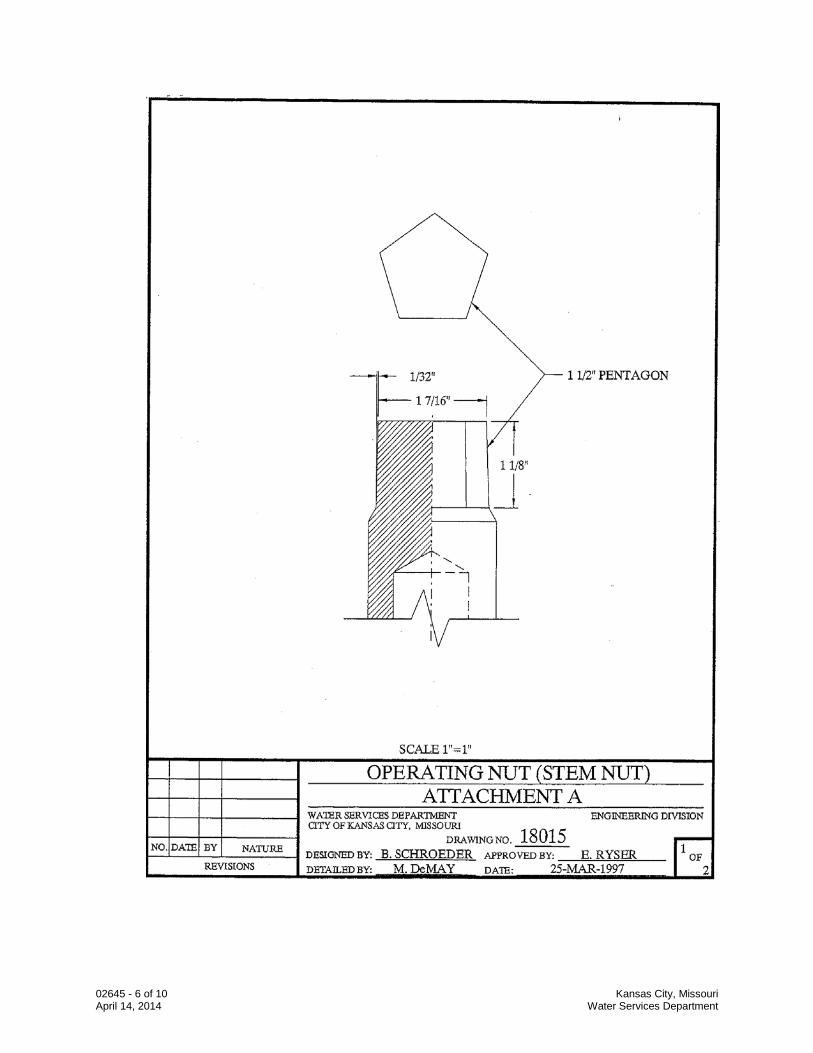
02645 - 6 of 10 Kansas City, Missouri April 14, 2014 Water Services Department
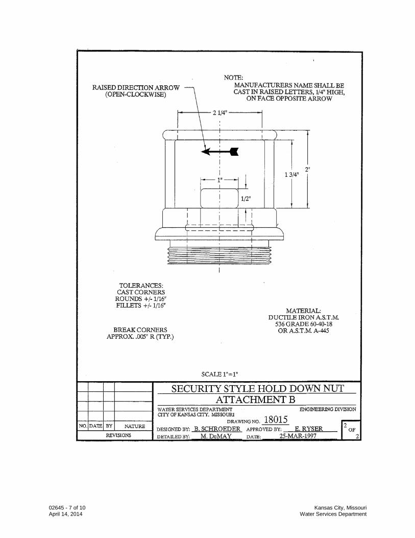
02645 - 7 of 10 Kansas City, Missouri April 14, 2014 Water Services Department
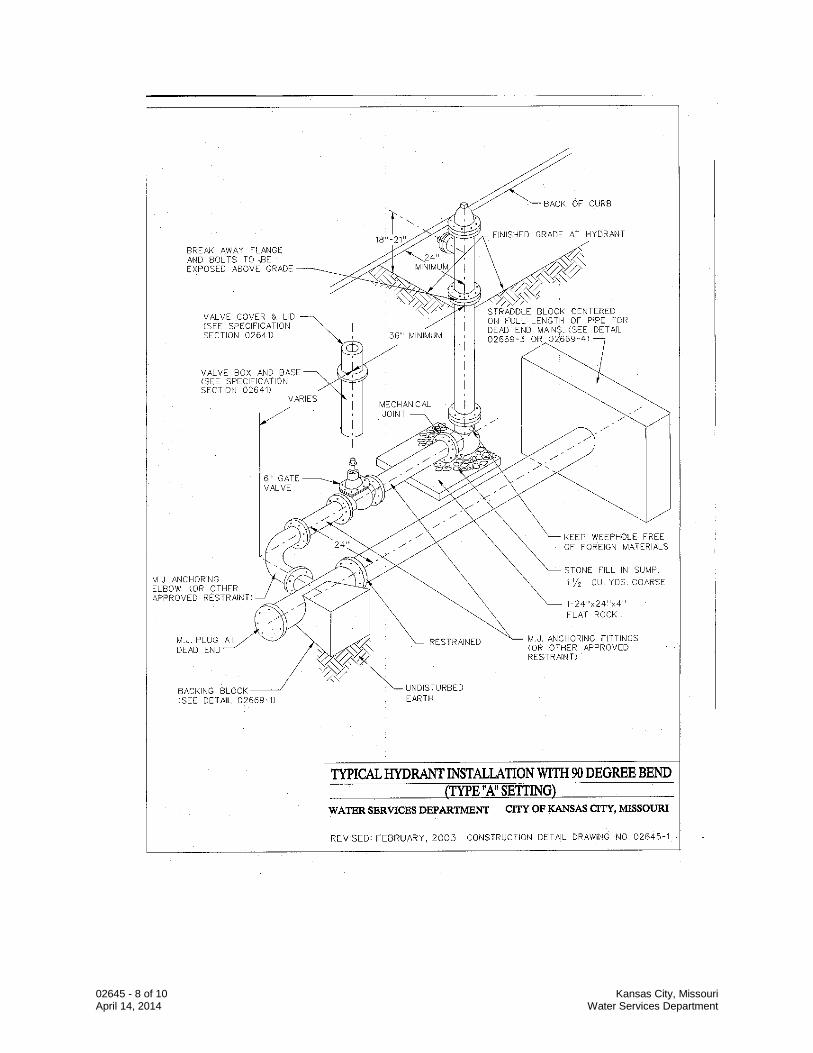
02645 - 8 of 10 Kansas City, Missouri April 14, 2014 Water Services Department
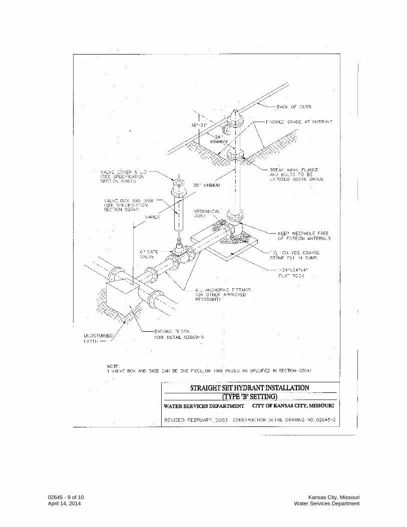
02645 - 9 of 10 Kansas City, Missouri April 14, 2014 Water Services Department
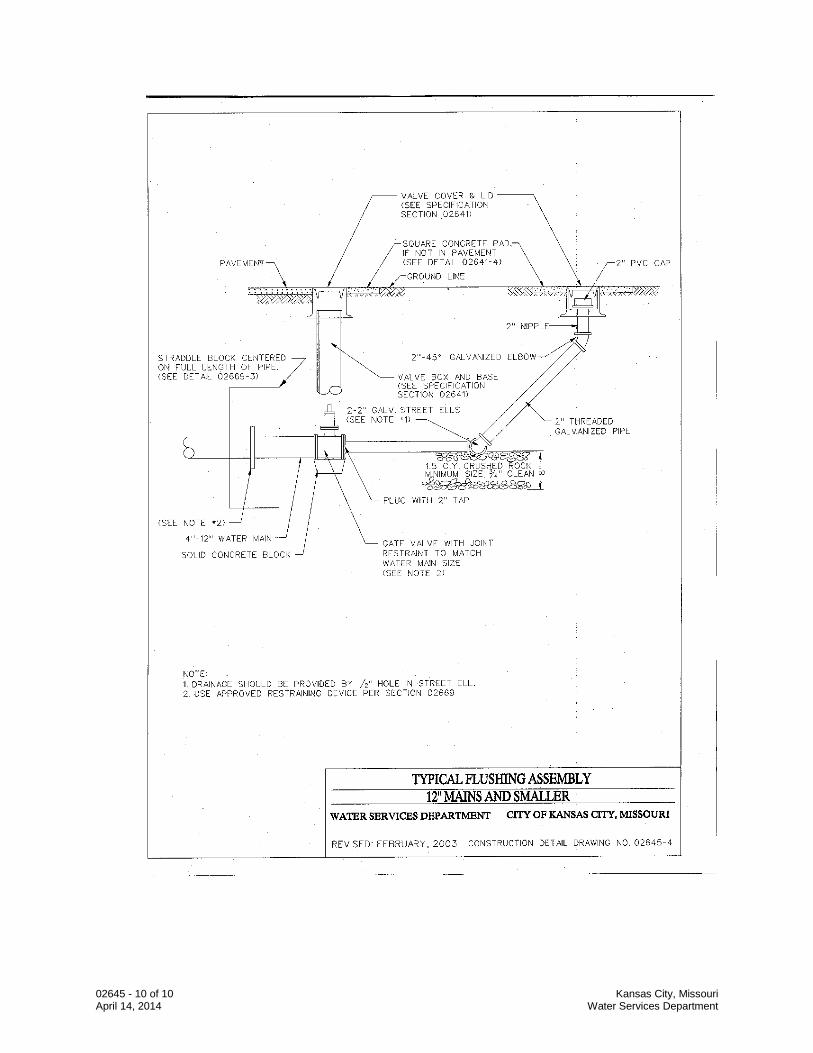
02645 - 10 of 10 Kansas City, Missouri April 14, 2014 Water Services Department
02669 - 1 of 8 Kansas City, Missouri April 11, 2014 Water Services Department
SECTION 02669
THRUST RESTRAINTS PART 1 GENERAL 1.1 Section Description
A. This section provides for the required restraining devices to limit movement of pipe and fittings.
1.2 Section Includes
A. Restrained Joints B. Concrete Blocking
1.3 Related Sections
A. Section 01300 – Submittals B. Section 01600 – Material and Equipment C. Section 02200 – Excavation and Trenching D. Section 02618 – Ductile Iron Pipe Water Main E. Section 02645 – Hydrants and Blowoff and Flushing Assemblies F. Section 03001 – Concrete G. Section 03200 – Concrete Reinforcement
1.4 Submittals
A. Follow the procedures for submittals provided in Section 01300 - Submittals. B. Submit shop drawings and descriptive details showing the size, length, and location
of each fitting and adjacent pipe, and the details of all anchorage and harnessing proposed.
1.5 Quality Assurance
A. The manufacturer shall be a company specializing in manufacturing the Products specified in this section with minimum three (3) years documented experience.
02669 - 2 of 8 Kansas City, Missouri April 11, 2014 Water Services Department
1.6 Delivery, Storage and Handling
A. Follow the provisions for the delivery, storage, protection and handling products to and at site provided in Section 01600 - Material and Equipment.
PART 2 PRODUCTS 2.2 Restrained Joints
A. Restrained Push-on joints for ductile iron pipe and fittings: American “Flex-Ring”, “Fast-Grip”, Clow “Super-Lock”; U.S. Pipe “TR Flex” or “Field Lok”, or Griffin “Snap-Lok”.
B. Restrained Mechanical Joints: EBAA Iron “Mega-Lug” or Ford uni-flange. “Mega-
Lug” shall not be used on plain end fittings.
C. Restrained joint fittings: One Bolt
D. Restrained joints for PCCP shall be as specified in Section 02619.
2.2 Concrete Blocking
A. Concrete shall be as per Section 03001. PART 3 EXECUTION 3.3 Reaction Anchorage and Blocking
A. Piping and fittings with push-on or mechanical joints, or similar joints subject to internal pressure shall be blocked, anchored, or harnessed to preclude separation of joints. All push-on and mechanical joint bends deflecting 11-1/4 degrees or more shall be provided with suitable blocking, anchors, joint harness, or other acceptable means for preventing movement of the pipe caused by internal pressure.
B. Concrete blocking shall extend from the fitting to solid undisturbed earth and shall be
installed so that all joints and bolts are accessible for repair. C. The dimensions of concrete blocking shall be as indicated on Construction Detail
Drawings numbered 02669-1, 02669-2, 02669-3, 02669-4 and 02669-5. If support against undisturbed earth cannot be obtained, restrain joints as specified in 3.2, Restrained Length (length shall be approved by CITY).
D. A maximum of eight (8) inches of backfill material may be placed over concrete
arch encasement or concrete blocking after the initial set, to aid in curing. No additional backfill shall be placed over arch encasement or blocking until the concrete has been in place for at least one (1) day.
02669 - 3 of 8 Kansas City, Missouri April 11, 2014 Water Services Department
E. Reaction blocking, anchorages, or other supports for fittings installed in fills or other unstable ground, above grade, or exposed within structures, shall be provided as required by the Construction Detail Drawings and as directed by the CITY.
F. All clamps, rods, bolts, and other metal accessories used in reaction anchorages, or
joint harness subject to submergence or contact with earth or other fill material and not encased in concrete shall be protected from corrosion by two coats of approved coal tar applied in the field to clean, dry metal surfaces. The first coat shall be dry and hard before the second coat is applied. Metal surfaces exposed above grade or within structures shall be painted with one prime coat and two finish coats of a paint acceptable to the CITY.
END OF SECTION
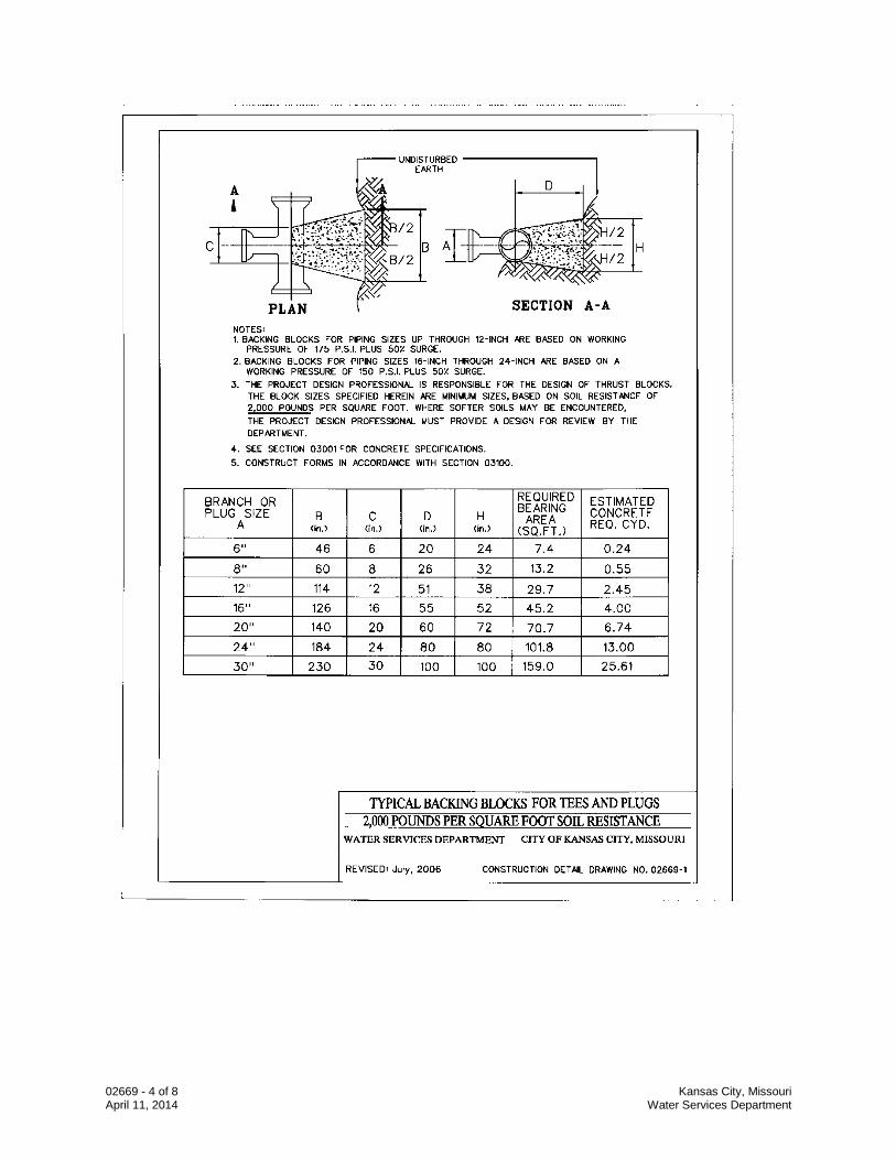
02669 - 4 of 8 Kansas City, Missouri April 11, 2014 Water Services Department
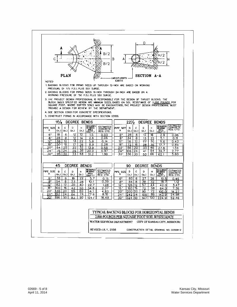
02669 - 5 of 8 Kansas City, Missouri April 11, 2014 Water Services Department
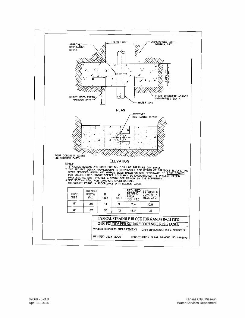
02669 - 6 of 8 Kansas City, Missouri April 11, 2014 Water Services Department
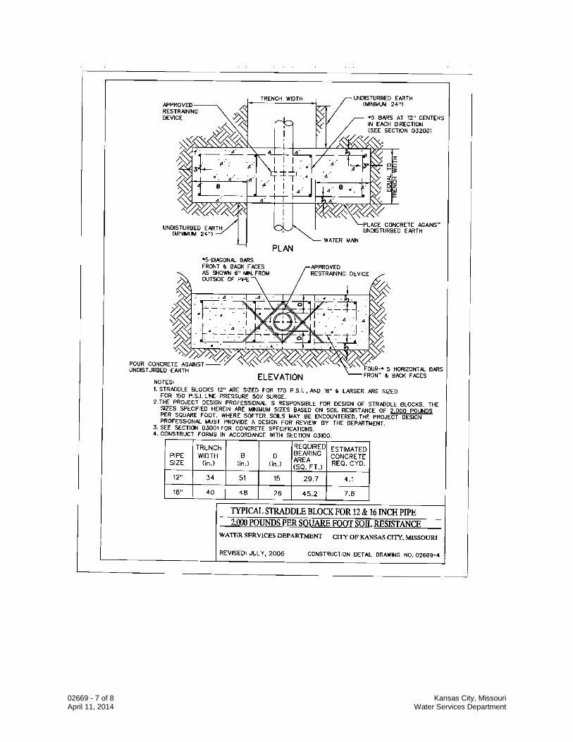
02669 - 7 of 8 Kansas City, Missouri April 11, 2014 Water Services Department
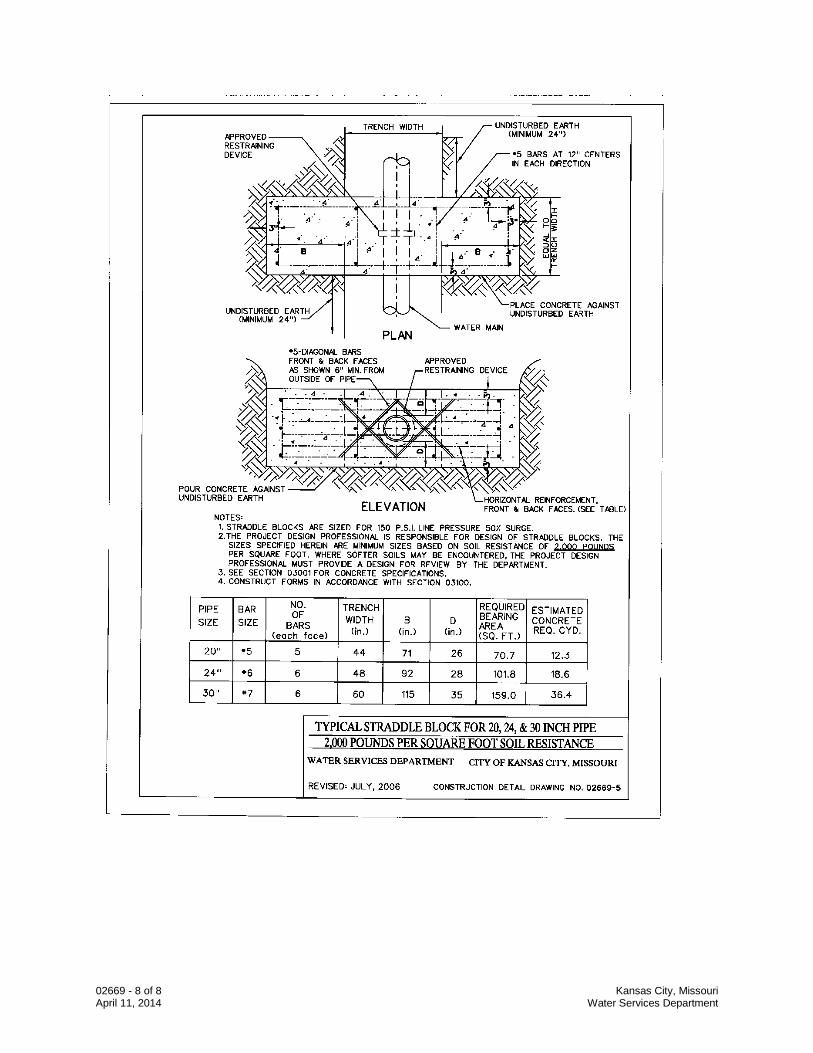
02669 - 8 of 8 Kansas City, Missouri April 11, 2014 Water Services Department
02675 - 1 of 6 Kansas City, Missouri April 11, 2014 Water Services Department
SECTION 02675 WATER MAIN TESTING, DISINFECTION AND DECHLORINATION PART 1 GENERAL 1.1 Section Description
A. This section provides for the required procedure for the water main testing, disinfection, and dechlorination prior to placing in service.
1.2 Section Includes
A. Corporation Cocks
B. Hydrostatic Testing C. Disinfection of Water Mains
1.3 Related Sections
A. Section 01000 – General Requirements B. Section 01300 – Submittals C. Section 01600 – Material and Equipment D. Section 02618 – Ductile Iron Pipe E. Section 02641 – Valves F. Section 02645 – Hydrants, Blowoff and Flushing Assemblies
1.4 References
A. AWWA C651 - Standards for Disinfecting Water Mains. 1.5 Submittals
A. Follow the procedures for submittals provided in Section 01300 – Submittals. B. Certificate: The Contractor shall certify in writing that cleanliness of water distribution
system meets or exceeds specified requirements. C. At the completion of the disinfection procedures, Contractor shall prepare a
Disinfection Report; including:
1. Type and form of disinfectant used. 2. Date and time of disinfectant injection start and time of completion.
02675 - 2 of 6 Kansas City, Missouri April 11, 2014 Water Services Department
3. Test locations. 4. Initial and 24 hour disinfectant residuals (quantity in treated water) in parts per
million for each outlet tested. 5. Date and time of post disinfectant flushing start and completion. 6. Disinfectant residual after flushing in parts per million for each outlet tested.
C. Contractor shall provide, at their expense, water sample collection and testing by a
MoDNR approved laboratory which shall prepare a Bacteriological Report; including:
1. Date issued, project name, and testing laboratory name, address, and telephone number.
2. Time and date of water sample collection, and testing. 3. Name of person collecting samples. 4. Test locations. 5. Initial and 24 hour disinfectant residuals in parts per million for each outlet
tested. 6. Coliform bacteria test results for each outlet tested. 7. Certification that water conforms, or fails to conform, to bacterial standards of
the Missouri Department of Natural Resources. 8. Bacteriologist's signature and authority.
1.6 Quality Assurance
A. Work shall be performed in accordance with AWWA C651. PART 2 PRODUCTS 2.1 Corporation Cocks
A. The Contractor will furnish and install a three-fourth inch (3/4") Corporation cock to be used in the testing and disinfection of each new main. The location of these corporation cocks shall be as directed by the CITY.
B. After the line has been tested and prior to placing the main in service, the Contractor
shall remove the corporation cock and replace it with a tapered brass plug.
02675 - 3 of 6 Kansas City, Missouri April 11, 2014 Water Services Department
PART 3 EXECUTION 3.1 Hydrostatic Testing
A. General
1. The entire main shall be tested (pressure test and allowable leakage test) immediately after construction as directed and witnessed by the CITY.
2. With approval of the CITY, the pressure test and leakage test may be
conducted simultaneously. However, should the Contractor be granted permission to make both tests simultaneously, the required test pressure shall be equal to or greater than that for pressure tests as specified below.
B. Pressure Test
1. After the trench has been backfilled, the test connections made and the main
filled with water, a minimum pressure of not less than the normal operating pressure (for the lowest point on the line) plus 50% for surge but in no case less than 160 psi for 12” and smaller mains and 225 psi for 16” and larger mains, unless otherwise stated, shall be maintained on the new water main for at least two (2) hours.
2. The Contractor shall furnish all pumps, piping, gauges, labor and other
materials and services necessary to bring the main up to the specified test pressure.
3. All exposed pipe, fittings, valves, hydrants and joints shall be inspected by the
CITY and all evidence of moisture appearing on the surface of the ground during the test shall be investigated by the Contractor by excavation where the pipe has been covered with backfill.
4. All defective pipe, fittings, valves or hydrants discovered during the pressure
test shall be removed and replaced by the Contractor and the pressure test shall be repeated until satisfactory to the CITY.
5. The Contractor shall furnish and install all temporary blow-off assemblies,
fittings, thrust blocks, and restraining devices required for temporary connections for flushing, pressure testing, chlorination, and de-chlorination of water mains.
C. Leakage Test
1. An allowable leakage test shall be conducted after the pressure test has been
satisfactorily completed. The Contractor shall maintain a minimum pressure in the new water main of 150 psi (or a minimum of 10 psi greater than the normal operating pressure of the system, if the normal operating pressure is lower than 140 psi ) for the lowest point on the line for at least two (2) hours.
02675 - 4 of 6 Kansas City, Missouri April 11, 2014 Water Services Department
2. Leakage shall be defined as the quantity of water that must be supplied into the newly laid pipe to maintain the specified leakage test pressure after the air has been expelled and the pipe has been filled with water.
3. No water main, or section thereof will be accepted if and while it has a leakage
rate in excess of that determined by the following formula:
L = .0000075 SD(P)1/2 /2 Where: L = Maximum permissible leakage in gallons for two hours. S = Length of pipe tested, in feet. D = Nominal internal diameter of the water main being tested in inches. P = Average test pressure in psi in the water main being tested.
4. Should the actual leakage exceed the allowable leakage, the test pressure shall
be maintained for an additional period of time as directed by the CITY so that the leakage location may be detected.
3.2 Disinfection of Water Mains
A. General
1. After completion of hydrostatic testing the Contractor shall flush and disinfect the entire main under the direction of CITY.
2. The Contractor shall prepare the main for disinfection by exposing the pipe at
all entry points where the chlorine will be introduced into the pipe and installing temporary blow-offs at all discharge ends.
3. Continuous feed method of chlorination is required. The slug method of
chlorination may be used only when directed by CITY.
B. Continuous Feed-Method
1. Water supplied from an approved source of supply shall be made to flow at a constant, measured rate into the new water main.
2. At a point not more than 10 ft downstream from the beginning of the new
main, water entering the new main shall receive a dose of chlorine fed at a constant rate such that the water will have not less than 60 mg/L free chlorine. To ensure that this concentration is achieved, the chlorine concentration should be measured at regular intervals.
3. As an optional procedure, water used to fill the new water main during the
application of chlorine shall be supplied through a temporary connection. This temporary connection shall be installed with an appropriate cross-
02675 - 5 of 6 Kansas City, Missouri April 11, 2014 Water Services Department
connection control device for backflow protection of the active distribution system. Chlorine application shall not cease until the entire main is filled with heavily chlorinated water. The chlorinated water shall be retained in the main for at least 24 hours, during which time all valves and hydrants shall be operated to ensure disinfection of the appurtenances. At the end of this 24-hour period, the treated water in all portions of the main shall have a residual of at least 45 mg/L free chlorine.
4. The preferred equipment for applying liquid chlorine is a solution-feed,
vacuum-operated chlorinator and a booster pump. The vacuum-operated chlorinator mixes the chlorine gas in solution water; the booster pump injects the chlorine-gas solution into the main to be disinfected. All connections shall be checked for tightness before the solution is applied to the main.
5. After the required retention period (24 hours), the 24 hour residual chlorine
sample shall be pulled, the heavily chlorinated water shall then be dechlorinated to 0 mg/L chlorine. A reducing agent shall be applied to the water before discharging, to neutralize thoroughly the chlorine residual remaining in the water. Two sets of Bac-T samples shall be taken, one immediately after the final flush, the second taken 24 hours later.
6. Contractor shall coordinate disinfectant testing and bacteriological testing to
demonstrate that the above requirements have been met.
C. Slug Method
1. Water supplied from an approved source of supply shall be made to flow at a constant, measured rate into the new water main.
2. At a point not more than 10 ft downstream from the beginning of the new
main, water entering the new main shall receive a dose of chlorine fed at a constant rate such that the water will have not less than 100 mg/L free chlorine. To ensure that this concentration is achieved, the chlorine concentration should be measured at regular intervals.
3. The chlorine shall be applied continuously and for a sufficient period to develop
a solid column, or “slug” of chlorinated water that will, as it moves through the main, expose all interior surfaces to a concentration of approximately 100 mg/L for at least 3 hours
4. If at any time chlorine residual drops below 50 mg/L, the flow shall be stopped.
Then the chlorination equipment shall be relocated at the head of the slug, and, as flow is resumed, chlorine shall be applied to restore the free chlorine in the slug to not less than 100 mg/L.
5. After the required retention period (at least 3 hours), the 3 hour residual
chlorine sample shall be pulled, the heavily chlorinated water shall then be dechlorinated to 0 mg/L chlorine. A reducing agent shall be applied to the water before discharging, to neutralize thoroughly the chlorine residual remaining in the water. Two sets of Bac-T samples shall be taken, one immediately after the final flush, the second taken 24 hours later.
02675 - 6 of 6 Kansas City, Missouri April 11, 2014 Water Services Department
6. Contractor shall co-ordinate disinfectant testing and bacteriological testing to
demonstrate that the above requirements have been met.
END OF SECTION
02930 - 1 of 9 Kansas City, Missouri April 14, 2014 Water Services Department
SECTION 02930 SEEDING PART 1 GENERAL 1.1 Section Description
A. This section provides for areas to be restored with seeding materials. 1.2 Section Includes
A. Soil for Repairs B. Mulch C. Fertilizer and Herbicide D. Seed
1.3 Related Sections A. Section 01300 – Submittals B. Section 01600 – Material and Equipment C. Section 01900 – Project Closeout D. Section 02200 - Excavation and Trenching E. Section 02931 - Sodding
1.4 References
A. FS O-F-241 - Fertilizers, Mixed, Commercial. 1.5 Definitions
A. Seeding areas: All areas disturbed by construction operations including areas of cut and fill, trenching, temporary roads, and temporary staging or storage areas shall be seeded unless otherwise specified.
B. Sequence of Work: Sequence shall be clearing, grading, fertilizing, tilling, seeding,
covering and firming, and application of mulch. All seeded areas shall be mulched with grain straw or wood cellulose fiber, or covered with erosion control fabric.
C. Weeds: Include Dandelion, Jimsonweed, Quackgrass, Horsetail, Morning Glory,
Rush Grass, Mustard, Lambsquarter, Chickweed, Cress, Crabgrass, Canadian Thistle, Nutgrass, Poison Oak, Blackberry, Tansy Ragwort, Bermuda Grass, Johnson Grass, Poison Ivy, Nut Sedge, Nimble Will, Bindweed, Bent Grass, Wild Garlic, Perennial Sorrel, and Brome Grass.
02930 - 2 of 9 Kansas City, Missouri April 14, 2014 Water Services Department
1.6 Submittals
A. Follow the procedures for submittals provided in Section 01300 - Submittals. B. Invoices and Analysis Labels: A copy of the supplier’s invoices for all seed, mulch,
and fertilizer which shows the quantity by weight purchased and a representative label bearing the manufacturer’s or vendor’s guaranteed statement of analysis shall be submitted to the CITY for review and approval to assure compliance with specified requirements for quality and application rates.
1.7 Quality Assurance
A. Comply with regulatory agencies for fertilizer and herbicide composition. B. Seed and Fertilizer shall be labeled in accordance with U.S. Department of
Agriculture Rules and Regulations under the Federal Seed Act and State seed laws. Seed shall be furnished in sealed standard containers of the vendor. Each seed container shall bear the name, trade name, or trade mark, and a warranty of the producer and a certificate of the percentage of the purity and germination of each kind of seed specified. Seed which has become wet, moldy, or otherwise damaged in transit or in storage will not be acceptable
C. All seeding work shall be performed by a contractor having demonstrated
experience in seeding on projects of similar size. The work shall be prepared by experienced personnel who are familiar with the required work and who are under the supervision of a qualified foreman at all times when the work is in progress.
D. The Contractor shall have access to equipment such as a fertilizer spreader, farm
tractor with tilling equipment, grass seed drill or cultipacker type seeder, mulch blower, or hydromulcher for application of mulch, and straight serrated disk for crimping mulch into the soil.
1.8 Delivery, Storage, and Handling
A. Follow the provisions for the delivery, storage, protection and handling Product to and at site provided in Section 01600 - Material and Equipment.
B. Deliver grass seed mixture in sealed containers. Seed in damaged packaging is not
acceptable. C. Deliver fertilizer in waterproof bags showing weight, chemical analysis, and name of
manufacturer. PART 2 PRODUCTS 2.2 Soil for Repairs
A. The soil used in any repair work shall be of a quality at least equal to that in areas adjacent to the area to be repaired. Soil shall be free from tree roots, clay balls,
02930 - 3 of 9 Kansas City, Missouri April 14, 2014 Water Services Department
stones, and other materials that hinder grading, planting, and maintenance operations and that is free from noxious and other objectionable weed seeds and toxic substances.
2.3 Mulch
A. Vegetative Type Mulch:
1. Vegetative Type Mulch shall be baled, dry, unweathered, no discoloration or mold damage.
2. A minimum of 50 percent of weight of the herbage making up the material
shall be a minimum of 10 inches in length. Mulch material containing an excessive amount of weed and crop seeds will not be acceptable.
B. Wood Cellulose Fiber Mulch:
1. Prepared from virgin wood fibers containing no substance that might inhibit
germination or growth of grass seed. Mulch shall be dyed an appropriate color to allow visual maintenance of its application and shall contain a tacking agent. The wood cellulose fibers shall be evenly dispersed and suspended when agitated in water. When sprayed uniformly on the surface of the soil, the fiber shall form a blotter-like ground cover that readily absorbs water and allows infiltration to the underlying soil. Weight specifications from suppliers, and for all applications, shall refer only to air dry weight of the fiber, at a standard equivalent of 10 percent nominal moisture content.
2. The mulch material shall be supplied in packages having a gross weight not
in excess of 100 pounds and shall be marked by the manufacturer to show the air-dry weight. Suppliers shall certify that laboratory and field testing of their product has been conducted. Certificates shall be submitted in accordance with Section 01300 and that it meets all of the foregoing requirements pertaining to wood cellulose fiber mulch.
2.4 Fertilizer and Herbicide
A. Starter Fertilizer:
1. Fertilizer shall be pelleted or granulated and shall be an approved brand composed of a “Slow Release Nitrogen” fertilizer in the 1-2-1 range, such as 13-25-12 grade. Fertilizer shall be uniform in composition, free flowing and suitable for application with approved equipment.
B. Herbicide:
1. Pre-emergent herbicide shall be siduron (Tupersan). In areas where
herbicide runoff may compromise water quality, herbicide should be Glyphosage, N-(phosphonomethyl) glycine in a form approved for aquatic applications.
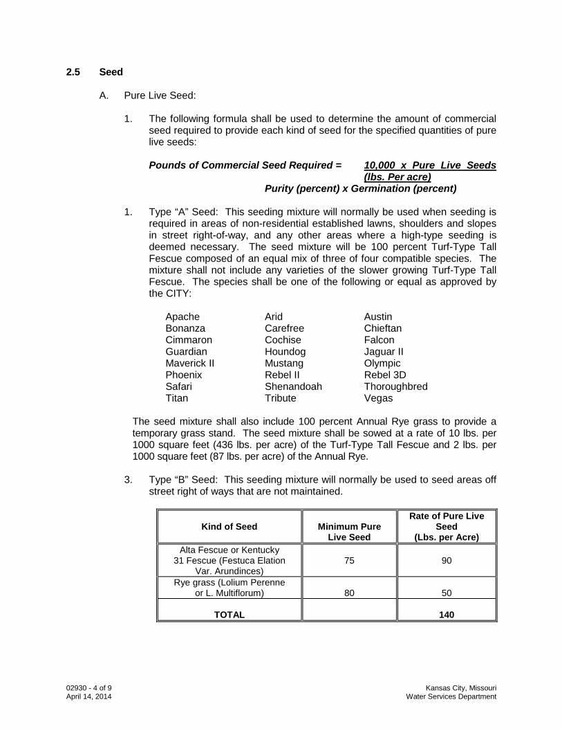
02930 - 4 of 9 Kansas City, Missouri April 14, 2014 Water Services Department
2.5 Seed
A. Pure Live Seed:
1. The following formula shall be used to determine the amount of commercial seed required to provide each kind of seed for the specified quantities of pure live seeds:
Pounds of Commercial Seed Required = 10,000 x Pure Live Seeds
(lbs. Per acre) Purity (percent) x Germination (percent)
1. Type “A” Seed: This seeding mixture will normally be used when seeding is required in areas of non-residential established lawns, shoulders and slopes in street right-of-way, and any other areas where a high-type seeding is deemed necessary. The seed mixture will be 100 percent Turf-Type Tall Fescue composed of an equal mix of three of four compatible species. The mixture shall not include any varieties of the slower growing Turf-Type Tall Fescue. The species shall be one of the following or equal as approved by the CITY:
Apache Arid Austin Bonanza Carefree Chieftan Cimmaron Cochise Falcon Guardian Houndog Jaguar II Maverick II Mustang Olympic Phoenix Rebel II Rebel 3D Safari Shenandoah Thoroughbred Titan Tribute Vegas The seed mixture shall also include 100 percent Annual Rye grass to provide a
temporary grass stand. The seed mixture shall be sowed at a rate of 10 lbs. per 1000 square feet (436 lbs. per acre) of the Turf-Type Tall Fescue and 2 lbs. per 1000 square feet (87 lbs. per acre) of the Annual Rye.
3. Type “B” Seed: This seeding mixture will normally be used to seed areas off
street right of ways that are not maintained.
Kind of Seed
Minimum Pure
Live Seed
Rate of Pure Live Seed
(Lbs. per Acre) Alta Fescue or Kentucky
31 Fescue (Festuca Elation Var. Arundinces)
75
90
Rye grass (Lolium Perenne or L. Multiflorum)
80
50
TOTAL
140
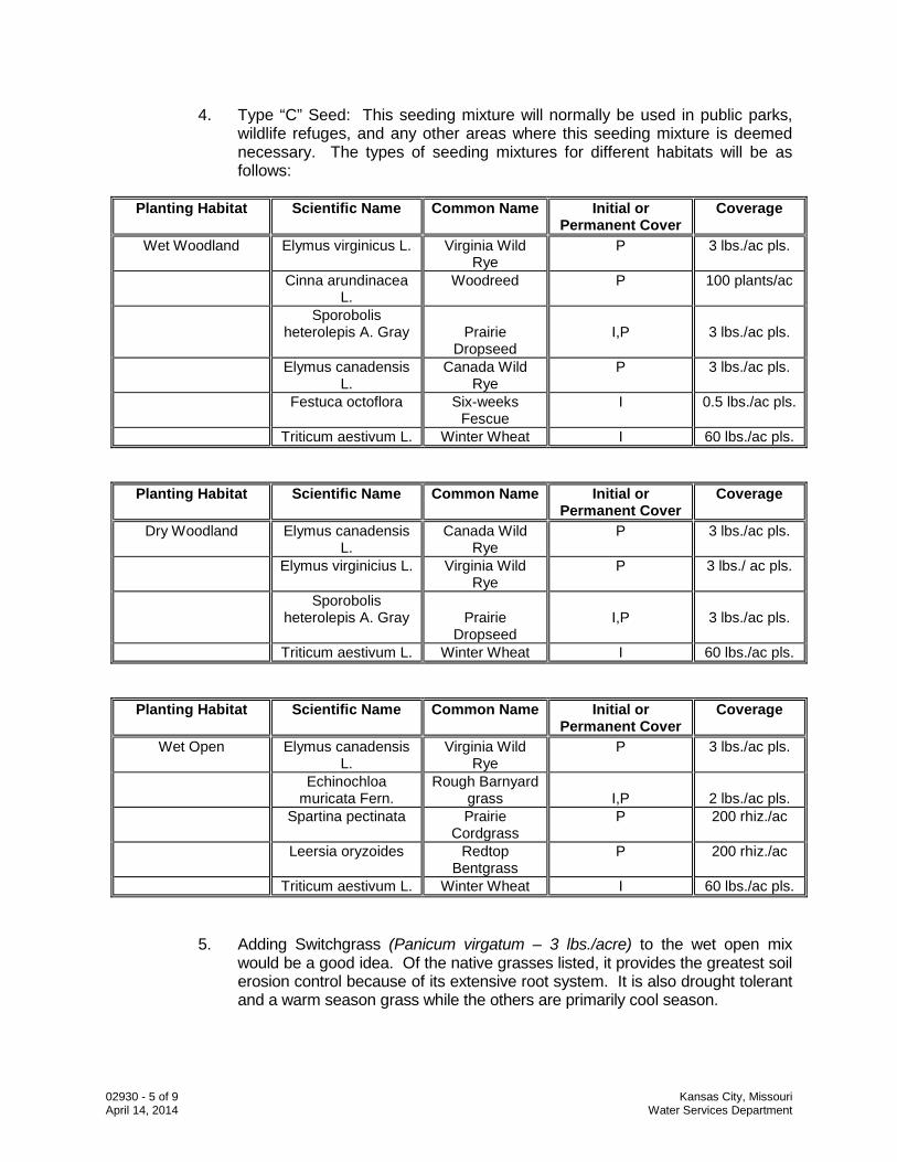
02930 - 5 of 9 Kansas City, Missouri April 14, 2014 Water Services Department
4. Type “C” Seed: This seeding mixture will normally be used in public parks, wildlife refuges, and any other areas where this seeding mixture is deemed necessary. The types of seeding mixtures for different habitats will be as follows:
Planting Habitat Scientific Name Common Name Initial or
Permanent Cover Coverage
Wet Woodland Elymus virginicus L. Virginia Wild Rye
P 3 lbs./ac pls.
Cinna arundinacea L.
Woodreed P 100 plants/ac
Sporobolis heterolepis A. Gray
Prairie
Dropseed
I,P
3 lbs./ac pls.
Elymus canadensis L.
Canada Wild Rye
P 3 lbs./ac pls.
Festuca octoflora Six-weeks Fescue
I 0.5 lbs./ac pls.
Triticum aestivum L. Winter Wheat I 60 lbs./ac pls.
Planting Habitat Scientific Name Common Name Initial or Permanent Cover
Coverage
Dry Woodland Elymus canadensis L.
Canada Wild Rye
P 3 lbs./ac pls.
Elymus virginicius L. Virginia Wild Rye
P 3 lbs./ ac pls.
Sporobolis heterolepis A. Gray
Prairie
Dropseed
I,P
3 lbs./ac pls.
Triticum aestivum L. Winter Wheat I 60 lbs./ac pls.
Planting Habitat Scientific Name Common Name Initial or Permanent Cover
Coverage
Wet Open Elymus canadensis L.
Virginia Wild Rye
P 3 lbs./ac pls.
Echinochloa muricata Fern.
Rough Barnyard grass
I,P
2 lbs./ac pls.
Spartina pectinata Prairie Cordgrass
P 200 rhiz./ac
Leersia oryzoides Redtop Bentgrass
P 200 rhiz./ac
Triticum aestivum L. Winter Wheat I 60 lbs./ac pls.
5. Adding Switchgrass (Panicum virgatum – 3 lbs./acre) to the wet open mix would be a good idea. Of the native grasses listed, it provides the greatest soil erosion control because of its extensive root system. It is also drought tolerant and a warm season grass while the others are primarily cool season.
02930 - 6 of 9 Kansas City, Missouri April 14, 2014 Water Services Department
PART 3 EXECUTION 3.6 Preparation of Subsoil
A. General:
1. The work shall not be started until substantially all earthwork has been completed in the area to be seeded. The topsoil spread and finish grading shall be completed immediately before the seeding work is started.
B. Clearing:
1. Prior to grading and tilling, vegetation that may interfere with operations shall
be mowed, grubbed, and raked. The collected material shall be removed from the site. The surface shall be cleared of stumps, stones, cable, wire, and other materials that might hinder the work or subsequent maintenance.
C. Grading:
1. Establish and maintain grades, in a true and even condition. Eroded areas
and areas having inadequate drainage, as indicated by ponding of water, shall be filled. Ruts, deep tracks, dead furrows, and ridges shall be eliminated.
D. Cleanup:
1. Within reasonable time after completion of the construction operations, the
entire area shall be cleared of excess soil and waste material, including, but not limited to, stones, stumps, roots, brush, wire, grade stakes, and all objects that might be a hindrance to maintenance operations or affect the visual appearance of the site. All roads over which hauling operations have been conducted, regardless of the type of surfacing, shall be kept clean, and soil clods and debris left on the surface shall be removed. The wheels of vehicles shall be cleaned to avoid leaving soil upon the surface of roads, walks, and other surfaced areas.
3.7 Fertilizing
A. Application of Fertilizer: Fertilizer as specified shall be applied within 24 hours prior to the tilling operation. The fertilizer shall be distributed over the entire area to be seeded at the rate of 200 pounds per acre, and incorporated into the soil to a depth of at least 4 inches by disking or harrowing methods. Fertilizing rate is equivalent to 2.3 pounds per 500 square feet.
3.8 Seeding
A. Preparation of Seed Bed: 1. After fertilizer has been applied, the areas to be seeded shall be tilled to a
depth of at least 4 inches by disking, plowing, harrowing, or other accepted
02930 - 7 of 9 Kansas City, Missouri April 14, 2014 Water Services Department
methods until the soil is well pulverized and smoothed with a weighted spike-tooth harrow, railroad chains, or bridge timber float drag. When a chisel plow is used, the chisels shall be set not more than 10 inches apart and the areas shall be cross or double-tilled. All areas shall be left smooth for ease of mowing. All operations shall be done in a direction parallel to the contour lines on the slope and not uphill or downhill. Areas tilled shall be maintained until seeding and mulching is complete to insure a smooth area with no gullies or depressions.
B. Application of Seed:
1. Seeding equipment calibration tests shall be made in the presence of the
CITY to determine the equipment setting required to apply the seed at the specified rates. Markers shall be used to ensure that no skips occur between successive passes of the seeder. If unplanted skips and areas are noted after germination and the growth of the grass, the unplanted areas shall be prepared again, fertilized, seeded, compacted, protected with herbicide (Section 3.4.A) and mulched (Section 3.4.B) as if none of those steps had previously taken place. The seed box shall be kept at least half full during seeding operations to ensure even distribution of seed over all the areas seeded. The types of acceptable seeding depending upon the area are as follows:
2. All seeding work shall be done between the dates of February 1 and April 15
for spring planting or August 15 and October 15 for fall planting. Sowing shall be accomplished by use of an approved mechanical seeder or drill (hand spreader can be used in small areas), making sure that successive seed strips overlap to provide uniform coverage. The mixtures shall be applied in a crossing pattern of two passes, each applying half of the seed required. Seed should be drilled to a depth of 1/2 inch. The sprigs (rhizomes) shall be broadcast evenly and uniformly on the soil surface.
C. Compaction:
1. Immediately following the completion of seeding operations, the entire area
shall be compacted by means of a roller weighing at least 60 but not more than 90 pounds per linear foot of roller or any other method approved by the CITY.
3.9 Seed Protection
A. Application of Herbicide:
1. Following completion of seeding operations, pre-emergent herbicide as specified shall be applied to all seeded areas at the rate suggested by the manufacturer.
B. Mulching:
1. Mulching shall be done within 24 hours following the seeding operation
except in the case of wood cellulose type mulch.
02930 - 8 of 9 Kansas City, Missouri April 14, 2014 Water Services Department
2. Vegetative Type Mulch: Straw mulch shall be spread uniformly in a
continuous blanket at a depth of not less than 1-1/2 inches and not more than 2 inches loose measurement (approximately 1-1/2 to 2 tons per acre). Mulch shall be spread by hand or by a blower type mulch spreader. Blower type mulch spreaders shall be adjusted and operated in such a manner as to prevent excessive breakage of the mulch material. If this cannot be accomplished, the mulch shall be spread by hand. Care shall be exercised to ensure that all wire from baled hay is collected as it is removed from the bale. Mulching shall be started at the windward side of relatively flat areas, or at the upper part of a steep slope, and continued uniformly until the area is covered. The mulch shall not be bunched.
a. No mulch shall be spread unless it can be anchored on the same day.
3. Anchoring Straw Mulch: The straw mulch shall be anchored in the soil to a
depth of 2 to 3 inches by a notched disk set straight or a mulch crimping machine. The machine shall be weighted and operated in such a manner to secure the mulch firmly in the ground to form a soil binding mulch and prevent loss or bunching of straw by wind. Two or more passes may be required to anchor the mulch to the satisfaction of the CITY.
4. Application of Wood Cellulose Fiber: Wood cellulose fiber mulch shall be
applied with a hydromulcher at not less than 1000 pounds per acre. Precautionary measures shall be taken in preventing overspray on structures, paving, and plantings.
3.10 Maintenance
A. Watering:
1. Promptly after seeding and mulching, wet the seedbed thoroughly. Watering shall continue so as to keep all areas moist throughout the germination period.
B. Water Usage:
1. Water used in this work shall be furnished by the Contractor and shall be
suitable for irrigation and free from ingredients harmful to plant life. All watering equipment required for the work shall be furnished by the Contractor. Water shall be taken from adjacent fire hydrants or public water lines only through hydrant connections permitted and issued by CITY. Written approval from the property owner shall be obtained prior to the use of suitable water from ponds or creeks. Water from private owners shall also be metered.
C. Maintenance of Area:
1. The Contractor shall be responsible for maintaining all seeded areas until
acceptance by the CITY. If at any time before acceptance of the completed contract, any portion of the seeded surface becomes gullied or otherwise
02930 - 9 of 9 Kansas City, Missouri April 14, 2014 Water Services Department
damaged, or the seeding has been damaged or destroyed, the affected portion shall be cleared of stones, etc. and repaired to re-establish the specified condition prior to the acceptance of the work.
2. In established yards, shoulders and slopes in street right-of-way, and any
other areas where a Type “A” seeding is necessary, all newly seeded grassed areas shall be kept in a healthy growing condition by watering, weeding, mowing, trimming, edging, etc., until completion and acceptance by CITY. The seeded areas shall be mowed with approved mowing equipment to a height of 3 inches whenever the average height of vegetation becomes 6 inches.
3. Turf grass of one-square foot or more that does not show definite growth and
establishment shall be re-seeded in accordance with all requirements of this section including soil preparation and mulching. The Contractor shall continue the care and maintenance of all seeded areas as specified above until all work of this project has been satisfactorily completed and all deficiencies have been corrected at which time final inspection shall be made.
4. Areas Off of Street Right-of-Way (Type “B” Seed): All seeded areas shall be
maintained until acceptance by the Engineer. Maintenance shall include repair of erosion damage, re-seeding, including all preparation requirements maintenance of mulch, and watering.
END OF SECTION
02931 - 1 of 6 Kansas City, Missouri April 14, 2014 Water Services Department
SECTION 02931 SODDING PART 1 GENERAL 1.1 Section Description
A. This section provides for areas to be restored with sodding materials. 1.2 Section Includes
A. Sod B. Fertilizer
1.3 Related Sections
A. Section 01300 – Submittals B. Section 01600 – Material and Equipment C. Section 01900 – Project Closeout D. Section 02200 - Excavation and Trenching E. Section 02930 - Seeding
1.4 References
A. ASPA (American Sod Producers Association) - Guideline Specifications to Sodding. B. FS O-F-241 - Fertilizers, Mixed, Commercial.
1.5 Definitions
A. Sodding areas: All established lawn areas that have been disturbed by construction operations including areas of cut and fill, trenching, temporary roads, and temporary staging or storage areas shall be sodded unless otherwise specified.
B. Sequence of Work: Sequence shall be clearing, grading, fertilizing, tilling, and
sodding. C. Weeds: Includes Dandelion, Jimsonweed, Quackgrass, Horsetail, Morning Glory,
Rush Grass, Mustard, Lambsquarter, Chickweed, Cress, Crabgrass, Canadian Thistle, Nutgrass, Poison Oak, Blackberry, Tansy Ragwort, Bermuda Grass, Johnson Grass, Poison Ivy, Nut Sedge, Nimble Will, Bindweed, Bent Grass, Wild Garlic, Perennial Sorrel, and Brome Grass.
02931 - 2 of 6 Kansas City, Missouri April 14, 2014 Water Services Department
1.6 Submittals
A. Follow the procedures for submittals provided in Section 01300 - Submittals. 1.7 Quality Assurance
A. Comply with regulatory agencies for fertilizer and herbicide composition. B. All sodding work shall be performed by a contractor having demonstrated
experience in sodding on projects of similar size. The work shall be prepared by experienced personnel who are familiar with the required work and who are under the supervision of a qualified foreman at all times when the work is in progress.
C. Sod: Shall be a minimum age of 18 months, with root development that will support
its own weight without tearing, when suspended vertically by holding the upper two corners.
D. Submit sod certification for grass species and the location of sod source. E. Sod Producer: Shall be a company specializing in sod production and harvesting
with minimum three years documented experience. 1.8 Delivery, Storage, and Handling
A. Follow the provisions for the delivery, storage, protection and handling Products to and at site provided in Section 01600 - Material and Equipment.
B. Deliver sod in rolls. Protect exposed roots from dehydration.
C. Do not deliver more sod than can be laid within 24 hours. Sod harvested more than
48 hours prior to placement will be rejected and shall be removed immediately from the site.
PART 2 PRODUCTS 2.2 Sod
A. General:
1. The sod to be used as source material shall be a thick stand of Kentucky Blue Grass, Turf Type Tall Fescue, Bermuda Grass, Zoysia Grass or other grasses as required. The sod shall contain a growth of not more than 1 percent of other grasses and clovers, shall be free from all prohibited and noxious weeds.
2. Broken pads and torn or uneven ends will not be acceptable. Standard size
sections shall be strong enough to support their own weight and should retain their size and shape when suspended vertically from a firm grasp on the upper 10 percent of the section. Sod shall not be harvested or transplanted
02931 - 3 of 6 Kansas City, Missouri April 14, 2014 Water Services Department
with moisture content (excessively dry or wet) that will adversely affect its survival.
3. Sod shall be relatively free of thatch, up to 1/2 inch allowable
(uncompressed). Sod shall be reasonably free of diseases, nematodes, and soil-borne insects. State nursery and/or plant materials laws require that all sod entering inter-state commerce be inspected and approved for sale. The same applies to sod being shipped intra-state. The inspections and approval must be made by the state agricultural department, office of the state entomologist.
4. Sod for golf courses and other areas as deemed necessary shall be of the
Kentucky Blue Grass and Turf Type Tall Fescue Grass as specified above. Bermuda Grass and Zoysia Grass sod will not be acceptable for these areas.
B. Turf Type Tall Fescue Sod:
1. Composed of an equal mix of three or four compatible species of 100 percent
Turf Type Tall Fescue. The mixture shall not include any varieties of the slower growing Turf Type Tall Fescue “Dwarf”. The species shall be one of the following:
Apache Arid Austin Bonanza Carefree Chieftan Cimmaron Cochise Falcon Guardian Houndog Jaguar II Maverick II Mustang Olympic Phoenix Rebel II Rebel 3D Safari Shenandoah Thoroughbred Titan Tribute Vegas
C. Kentucky Blue Grass and Turf Type Tall Fescue Sod:
1. Cut in strips of uniform thickness, the range of acceptable thickness shall be
1 1/2 to 2 inches; each strip containing at least one square yard. Sod shall be cut in strips not less than 12 inches wide.
D. Bermuda Grass or Zoysia Grass Sods:
1. Cut into strips of uniform thickness, the range of acceptable thickness shall
be 1 1/2 to 2 inches; each strip being not less than 12 inches wide and 24 inches long. Strips that crumble will not be acceptable.
2.3 Fertilizer
A. Fertilizer shall be inorganic 12.12.12 or 13.13.13 grade, uniform in composition, free flowing and suitable for application with approved equipment, delivered to the site in convenient containers, each fully labeled, conforming to applicable state
02931 - 4 of 6 Kansas City, Missouri April 14, 2014 Water Services Department
fertilizer laws, bearing the name, trade name, or trade mark and warranty of the producer.
PART 3 EXECUTION 3.4 Preparation of Subsoil
A. General:
1. The work shall not be started until all earthwork has been completed. Backfills and fills shall be properly compacted, the topsoil shall be spread and finish grading shall be completed immediately before the sodding work is started.
B. Preparation of Area:
1. Preparation of areas to be sodded shall include filling, reshaping eroded
areas, cleaning ditches and refinishing slopes to the established grade section.
C. Cleanup:
1. Within reasonable time after completion of the construction operations, the
entire area shall be cleared of excess soil and waste material, including, but not limited to, stones, stumps, roots, brush, wire, grade stakes, and all objects that might be a hindrance to maintenance operations or affect the visual appearance of the site. All roads over which hauling operations have been conducted, regardless of the type of surfacing, shall be kept clean, and soil clods and debris left on the surface shall be removed. The wheels of vehicles shall be cleaned to avoid leaving soil upon the surface of roads, walks, and other surfaced areas.
D. Preparation of Sod Bed:
1. After fertilizer has been applied, the areas to be sodded shall be tilled to a
depth of at least 2 inches by disking, plowing, harrowing, or other accepted methods until the soil is well pulverized and smoothed with a weighted spike-tooth harrow, railroad chains, or bridge timber float drag. When a chisel plow is used, the chisels shall be set not more than 10 inches apart and the areas shall be cross or double-tilled. All areas shall be left smooth for ease of mowing. All operations shall be done in a direction parallel to the contour lines on the slope and not uphill or downhill.
3.5 Fertilizing
A. Before tilling operations, fertilizer shall be spread uniformly at the rate of 300 pounds per acre. Fertilizing rate is equivalent to 3.5 pounds per 500 square feet.
02931 - 5 of 6 Kansas City, Missouri April 14, 2014 Water Services Department
3.6 Laying Sod
A. Application of Sod:
1. Kentucky Blue Grass and Turf Type Fescue sod shall not be placed during a drought, or during the period from June 1 to September 1, unless authorized by the CITY, and shall not be placed on frozen ground. Bermuda and Zoysia sods shall only be placed during the period from May 1 to October 15. The CITY reserves the right to delay the sodding of all types of sod or to vary the permissible sodding seasons, due to weather, soil conditions, or for other causes.
2. Sod shall be moist when it is placed. Sod strips shall be laid along contour
lines, commencing at the lowest point of the area and working upward. The transverse joints of sod strips shall be staggered and the sod carefully placed to produce tight joints. If necessary to walk excessively on newly laid sod, walking boards should be laid for this purpose. The sod shall be firm and watered immediately after it is placed. The “firming” shall be accomplished by application of a roller weighing not less than 60 nor more than 90 pounds per linear foot of roller or other approved method.
B. Anchoring Sod:
1. On 2:1 slopes, or steeper, the sod shall be anchored with 1/2 inch square by
8 inch long wooden pegs. The wooden pegs shall be driven into the ground 3 pegs to the square yard or other approved methods. Pegging shall be done immediately after sod is firmed.
3.7 Maintenance
A. Water Usage:
1. Water used in this work shall be furnished by the Contractor and will be suitable for irrigation and free from ingredients harmful to plant life. All watering equipment required for the work shall be furnished by the Contractor. Water shall be taken from adjacent fire hydrants or public water lines only through hydrant connections permitted and issued by CITY. Written approval from the property owner shall be obtained prior to the use of suitable water from ponds or creeks. Water from private owners shall also be metered.
B. Maintenance:
1. The Contractor shall be responsible for maintaining the installed grass sod
until all areas are complete and accepted by the CITY. Grass areas in excess of one square foot that are dead or in poor condition regarding color and quality shall be replaced including all sodded preparation steps, and fertilized at the Contractor’s expense prior to final acceptance.
2. The Contractor shall maintain the grass area for a minimum period of
approximately 30 days or until the grass reaches a mowing height of 4
02931 - 6 of 6 Kansas City, Missouri April 14, 2014 Water Services Department
inches. The Contractor shall notify the City that the installed grass is ready to be mowed, and upon approval, the Contractor shall cut and “bag” grass clippings to a height of 2 1/2 inches. Completion of the mowing and replanting of all dead or dying grass by the Contractor shall be required prior to final acceptance.
END OF SECTION