Embed Size (px)
Citation preview
LabVolt Series
Datasheet
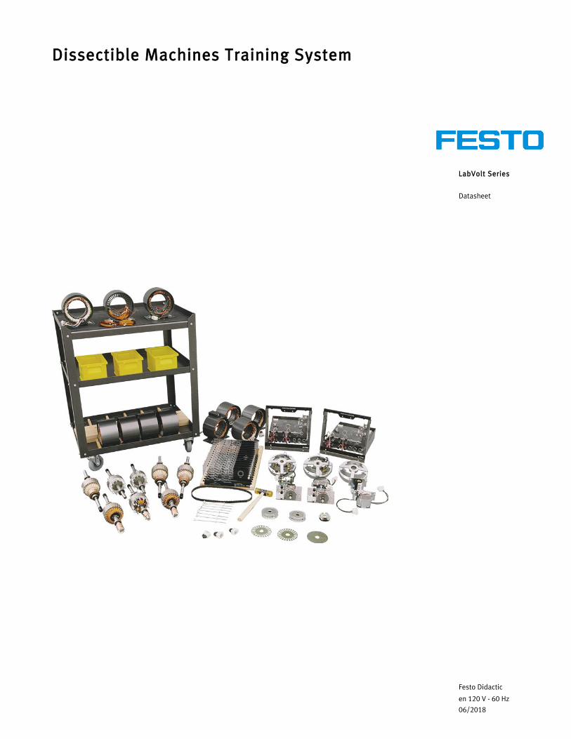
Dissectible Machines Training System
Festo Didactic
en 120 V - 60 Hz
06/2018
Dissectible Machines Training System, LabVolt Series
2 © Festo Didactic
Table of ContentsGeneral Description_______________________________________________________________________2Included Rotating Machines ________________________________________________________________3Optional Equipment Required to Operate the Rotating Machines _________________________________3Features & Benefits _______________________________________________________________________3List of Equipment_________________________________________________________________________3Manual _________________________________________________________________________________4Table of Contents of the Manual(s) __________________________________________________________4Optional Equipment_______________________________________________________________________4Optional Manual(s) _______________________________________________________________________4System Specifications _____________________________________________________________________4Equipment Description ____________________________________________________________________5Optional Equipment Description ____________________________________________________________7
General DescriptionThe Dissectible Machines Training System is an EMS training system that provides hands-on training in the construction and operation of rotating machines. The system fulfills educational requirements that include industrial applications of electric power technology and employs training equipment that has characteristics similar to industrial equipment.
The dissectible machines are assembled with the use of tools from a complete set of components, including stators, rotors, armatures, rheostats, and capacitors. Once assembled, they can be mounted on basic modules that lock into place on any EMS workstation. The components allow students to construct two different machines at the same time. Fifteen different machines can be constructed with these components.
Machine windings are connected to the faceplate of the module with polarized plugs, allowing for the correct interconnection of different types of machines. Schematic connections are silkscreened on the interchangeable face on the basic module. Once assembled, machines can be inserted into an EMS workstation and operated just like any preassembled machine. The workstation and equipment required to operate the assembled rotating machines are optional equipment.
Laboratory procedures in the correlated courseware guide students through assembly and disassembly of the various machines. Each component is identified, and a complete assembly drawing (exploded view) is supplied for each machine. A mobile work bench with a component storage area and a work surface for machine assembly are included in the system. An extra partially wound stator, a set of windings, and a set of loose laminations are included with the system to assist in the teaching of basic winding techniques.
All machines that can be built with the Dissectible Machines Training System can be ordered separately as fully assembled machines that can be disassembled and re-assembled by students.
Dissectible Machines Training System, LabVolt Series
© Festo Didactic 3
Included Rotating MachinesThe following machines can be assembled with the Dissectible Machines training system:
• DC Motor/Generator, Model 8211• Four-Pole Squirrel-Cage Induction Motor, Model 8221• Dahlander Two-Speed Constant Power Induction Motor, Model 8223• Dahlander Two-Speed Variable Torque Induction Motor, Model 8224• Dahlander Two-Speed Constant Torque Induction Motor, Model 8225• Three-Phase Wound-Rotor Induction Motor, Model 8231• Two-Phase Wound-Rotor Induction Motor, Model 8233• Three-Phase Synchronous Motor/Generator, Model 8241• Three-Phase Synchronous Reluctance Motor, Model 8246• Capacitor-Start Motor, Model 8251• Capacitor-Run Motor, Model 8253• Universal Motor, Model 8254• Two-Value Capacitor Motor, Model 8259• Triple-Rate Motor, Model 8266
Optional Equipment Required to Operate the Rotating MachinesThe rotating machines assembled using the Dissectible Machines Training System can be operated just like any preassembled machine. To do so, the following optional equipment is required:
• Workstation, Model 8134-2, or Mobile Workstation, Model 8110-2• Resistive Load, Model 8311• Power Supply, Model 8821-2• Connection Leads, Model 8951-L• Four-Quadrant Dynamometer/Power Supply, Model 8960-B• Data Acquisition and Control Interface, Model 9063-B
Features & Benefits• Rugged, high-quality components designed for hands-on training purposes• Complete assembly drawing (exploded view) for each machine• No tools required for machine assembly• Two machines can be assembled at the same time• Fifteen different machines can be constructed• Estimated program duration: 40 hours
List of Equipment
Qty DescriptionModel number
1 Work Bench for the Dissectible Machines Training System _____________________________________ 8120-002 Assembly Housing Module _______________________________________________________________ 8163-001 Dissectible Machine Parts _______________________________________________________________ 8201-101 Timing Belt ____________________________________________________________________________ 8942-00
Dissectible Machines Training System, LabVolt Series
4 © Festo Didactic
1 Required to operate the rotating machines assembled using the training system. Not required if the Workstation, Model 8134-2, is ordered.2 Required to operate the rotating machines assembled using the training system. Not required if the Workstation, Model 8110-2, is ordered.3 Required to operate the rotating machines assembled using the training system.4 Required to operate the rotating machines assembled using the training system.5 Required to operate the rotating machines assembled using the training system.6 Required to operate the rotating machines assembled using the training system.7 Required to operate the rotating machines assembled using the training system.
Manual
DescriptionManual number
Dissectible Machines (User Guide) ___________________________________________________________ 25853-00
Table of Contents of the Manual(s)Dissectible Machines (User Guide) (25853-00)• 1 The Equipment• 2 Direct Current Machine• 3 Split-Phase Capacitor-Start Motor• 4 Capacitor-Run Motor• 5 Two-Value Capacitor Motor• 6 Universal Motor• 7 Repulsion-Start/Induction-Run Motor (Optional)• 8 Three-Phase Wound-Rotor Induction Motor• 9 Three-Phase Squirrel Cage Induction Motor• 10 Synchronous Machine• 11 Synchronous Reluctance Motor• 12 Two-Speed Variable-Torque Motor• 13 Two-Speed Constant-Torque Motor• 14 Two-Speed Constant-HP Motor• 15 Triple-Rate Motor• 16 Two-Phase Wound-Rotor Induction Motor
Optional Equipment
Qty DescriptionModel number
1 Mobile Workstation _____________________________________________________________________ 8110-201 Workstation ___________________________________________________________________________ 8134-201 Resistive Load _________________________________________________________________________ 8311-001 Power Supply __________________________________________________________________________ 8821-201 Connection Lead Set ____________________________________________________________________ 8951-L01 Four-Quadrant Dynamometer/Power Supply _______________________________________________ 8960-B01 Data Acquisition and Control Interface ____________________________________________________ 9063-B0
1
2
3
4
5
6
7
Dissectible Machines Training System, LabVolt Series
© Festo Didactic 5
Optional Manual(s)
Qty DescriptionModel number
1 Dissectible Machines (Manuals on CD-ROM) _______________________________________________ 25853-A0
System SpecificationsParameter Value
Physical Characteristics
Intended Location On the floor (stands on casters)
Dimensions (H x W x D) 1000 x 550 x 750 mm (39.4 x 21.7 x 29.5 in)
Net Weight TBE
Equipment Description
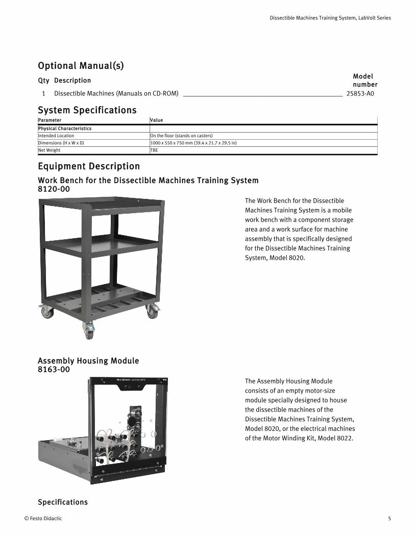
Work Bench for the Dissectible Machines Training System 8120-00
The Work Bench for the Dissectible Machines Training System is a mobile work bench with a component storage area and a work surface for machine assembly that is specifically designed for the Dissectible Machines Training System, Model 8020.
Assembly Housing Module 8163-00
The Assembly Housing Module consists of an empty motor-size module specially designed to house the dissectible machines of the Dissectible Machines Training System, Model 8020, or the electrical machines of the Motor Winding Kit, Model 8022.
Specifications

Dissectible Machines Training System, LabVolt Series
6 © Festo Didactic
Parameter Value
Can house:
DC Motor/Generator, Model 8211
Four-Pole Squirrel-Cage Induction Motor, Model 8221
Dahlander Two-Speed Constant Power Induction Motor, Model 8223
Dahlander Two-Speed Variable Torque Induction Motor, Model 8224
Dahlander Two-Speed Constant Torque Induction Motor, Model 8225
Three-Phase Wound-Rotor Induction Motor, Model 8231
Two-Phase Wound-Rotor Induction Motor, Model 8233
Three-Phase Synchronous Motor/Generator, Model 8241
Three-Phase Synchronous Reluctance Motor, Model 8246
Capacitor-Start Motor, Model 8251
Capacitor-Run Motor, Model 8253
Universal Motor, Model 8254
Two-Value Capacitor Motor, Model 8259
Triple-Rate Motor, Model 8266
Squirrel-Cage Induction Motor
Wound-Rotor Induction Motor
Three-Phase Synchronous Machine
Split-Phase Capacitor-Start Motor
Dissectible Machine Parts 8201-10The Dissectible Machine Parts is a kit that contains all the parts required to assemble all machines in the Dissectible Machines Training System, Model 8020.
SpecificationsParameter Value
Allows the Assembly of:
DC Motor/Generator, Dissectible, Model 8211-D
Four-Pole Squirrel-Cage Induction Motor, Dissectible, Model 8221-D
Dahlander Two-Speed Constant Power Induction Motor, Dissectible, Model 8223-D
Dahlander Two-Speed Variable Torque Induction Motor, Dissectible, Model 8224-D
Dahlander Two-Speed Constant Torque Induction Motor, Dissectible, Model 8225-D
Three-Phase Wound-Rotor Induction Machine, Dissectible, Model 8231-D
Two-Phase Wound-Rotor Induction Motor, Dissectible, Model 8233-D
Synchronous Motor/Generator, Dissectible, Model 8241-D
Three-Phase Synchronous Reluctance Motor, Dissectible, Model 8246-D
Split Phase/Capacitor-Start Motor, Dissectible, Model 8251-D
Capacitor-Run Motor, Dissectible, Model 8253-D
Universal Motor, Dissectible, Model 8254-D
Two-Value Capacitor Motor, Dissectible, Model 8259-D
Triple-Rate Motor, Dissectible, Model 8266-D
Timing Belt 8942-00
The Timing Belt is a high-quality industrial synchro-cog timing belt made of rubber whose teeth exactly mesh with the geared pulley fitted on the shaft of all 0.2 kW EMS machines. The Timing Belt is supplied in a fixed length appropriate for coupling two
adjacent EMS machines together without slippage between them.
Specifications

Dissectible Machines Training System, LabVolt Series
© Festo Didactic 7
Parameter Value
Physical Characteristics
Pitch 9.5 mm (0.375 in)
Pitch Length 819 mm (32.25 in)
Number of Teeth 86
Dimensions (Width) 12.7 mm (0.5 in)
Net Weight 0.1 kg (0.2 lb)
Optional Equipment Description
Mobile Workstation (Optional) 8110-20
The Mobile Workstation is a ready-for-use workstation that consists of two fully assembled modules: a Workstation, Model 8134-2, mounted on a Mobile Storage Cabinet, Model 89117-1. Four rubber-tire swivel casters allow easy movement of the workstation in the laboratory classroom. The lower portion of the workstation serves as a storage cabinet with two hinged panels and a lock handle. Immediately above the storage cabinet is a pullout work surface with a scuff- and burn-resistant laminate finish. The upper portion of the workstation consists of three rows of compartments designed to house EMS modules. Two of these
rows have full-height compartments while the other row has half-height compartments. Each row of full-height compartments can accommodate up to three full-size EMS modules or six half-size EMS modules, whereas the row of half-height compartments can accommodate up to three half-size EMS modules.
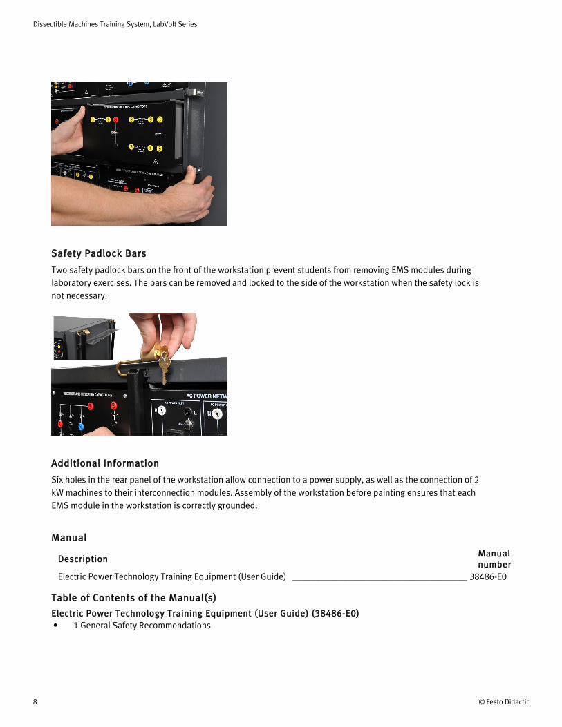
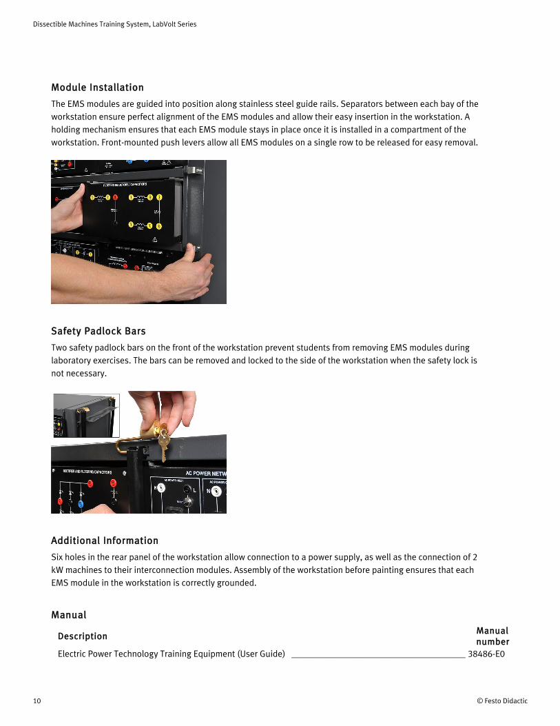
Module Installation
The EMS modules are guided into position along stainless steel guide rails. Separators between each bay of the workstation ensure perfect alignment of the EMS modules and allow their easy insertion in the workstation. A holding mechanism ensures that each EMS module stays in place once it is installed in a compartment of the workstation. Front-mounted push levers allow all EMS modules on a single row to be released for easy removal.
Dissectible Machines Training System, LabVolt Series
8 © Festo Didactic
Safety Padlock Bars
Two safety padlock bars on the front of the workstation prevent students from removing EMS modules during laboratory exercises. The bars can be removed and locked to the side of the workstation when the safety lock is not necessary.
Additional Information
Six holes in the rear panel of the workstation allow connection to a power supply, as well as the connection of 2 kW machines to their interconnection modules. Assembly of the workstation before painting ensures that each EMS module in the workstation is correctly grounded.
Manual
DescriptionManual number
Electric Power Technology Training Equipment (User Guide) ______________________________________ 38486-E0
Table of Contents of the Manual(s)
Electric Power Technology Training Equipment (User Guide) (38486-E0)• 1 General Safety Recommendations

Dissectible Machines Training System, LabVolt Series
© Festo Didactic 9
8 This add-on workstation allows modules from the Industrial Controls Training Systems, Models 8036, to be installed in the EMS workstation. Refer to the 8036 datasheet for more information.9 This add-on workstation allows modules from the Industrial Controls Training Systems, Models 8036, to be installed in the EMS workstation. Refer to the 8036 datasheet for more information.
• 2 System Power Requirements• 3 Quick Start Installation Guide• 4 Equipment Installation• 5 Modules Handling, Installation, and Removal• 6 Equipment Maintenance• A Connection of the Power Supply to the AC Power Network• B Description, Specifications, and Operation of the EMS Modules
Optional Equipment
Qty DescriptionModel number
1 Industrial Controls Single-Rail Workstation ________________________________________________ 3105-A01 Industrial Controls Double-Rail Workstation ________________________________________________ 3105-B0
SpecificationsParameter Value
Physical Characteristics
Intended Location On the floor (stands on casters)
Dimensions (H x W x D) 1660 x 935 x 665 mm (65.4 x 36.8 x 26.2 in)
Net Weight 77.1 kg (170 lb)
Workstation (Optional) 8134-20
The Workstation is a fully assembled workstation that serves the same purpose as the Mobile Workstation, Model 8110-2, but has no storage cabinet or pull-out work surface. This workstation is intended for use on a bench (not supplied) and is fitted with rubber feet to protect the bench top. Alternatively, this workstation can be mounted on either a Mobile Storage Cabinet, Model 89117-1, to make a Mobile Workstation, Model 8110-2, or on a Mobile Base, Model 88863, to make a mobile workstation without storage cabinet. In that case, it is possible to mount and lock a second
Workstation, Model 8134-2, on top of the first Workstation to double the space available for EMS modules.
The Workstation consists of three rows of compartments designed to house EMS modules. Two of these rows have full-height compartments while the other row has half-height compartments. Each row of full-height compartments can accommodate up to three full-size EMS modules or six half-size EMS modules whereas the row of half-height compartments can accommodate up to three half-size EMS modules.
8
9
Dissectible Machines Training System, LabVolt Series
10 © Festo Didactic
Module Installation
The EMS modules are guided into position along stainless steel guide rails. Separators between each bay of the workstation ensure perfect alignment of the EMS modules and allow their easy insertion in the workstation. A holding mechanism ensures that each EMS module stays in place once it is installed in a compartment of the workstation. Front-mounted push levers allow all EMS modules on a single row to be released for easy removal.
Safety Padlock Bars
Two safety padlock bars on the front of the workstation prevent students from removing EMS modules during laboratory exercises. The bars can be removed and locked to the side of the workstation when the safety lock is not necessary.
Additional Information
Six holes in the rear panel of the workstation allow connection to a power supply, as well as the connection of 2 kW machines to their interconnection modules. Assembly of the workstation before painting ensures that each EMS module in the workstation is correctly grounded.
Manual
DescriptionManual number
Electric Power Technology Training Equipment (User Guide) ______________________________________ 38486-E0

Dissectible Machines Training System, LabVolt Series
© Festo Didactic 11
10 This add-on workstation allows modules from the Industrial Controls Training Systems, Models 8036, to be installed in the EMS workstation. Refer to the 8036 datasheet for more information.11 This add-on workstation allows modules from the Industrial Controls Training Systems, Models 8036, to be installed in the EMS workstation. Refer to the 8036 datasheet for more information.
Table of Contents of the Manual(s)
Electric Power Technology Training Equipment (User Guide) (38486-E0)• 1 General Safety Recommendations• 2 System Power Requirements• 3 Quick Start Installation Guide• 4 Equipment Installation• 5 Modules Handling, Installation, and Removal• 6 Equipment Maintenance• A Connection of the Power Supply to the AC Power Network• B Description, Specifications, and Operation of the EMS Modules
Optional Equipment
Qty DescriptionModel number
1 Industrial Controls Single-Rail Workstation ________________________________________________ 3105-A01 Industrial Controls Double-Rail Workstation ________________________________________________ 3105-B01 Dust Cover for Workstations ______________________________________________________________ 8991-001 Mobile Base __________________________________________________________________________ 88863-001 Mobile Storage Cabinet ________________________________________________________________ 89117-10
SpecificationsParameter Value
Physical Characteristics
Intended Location On a table able to support the weight of the workstation and installed equipment
Dimensions (H x W x D) 890 x 935 x 465 mm (35.0 x 36.8 x 18.3 in)
Net Weight 31.8 kg (70 lb)
Resistive Load (Optional) 8311-00
The Resistive Load consists of a module housing nine wire-wound power resistors arranged in three identical banks. Each bank consists of three resistors connected in parallel that can be switched on or off with toggle switches to obtain various resistance values. This allows the total (equivalent) resistance of each bank to be increased or decreased by steps.
Six safety banana jacks on the module front panel provide access to each resistor bank. The three resistor banks can be connected separately for operation in three-phase circuits. Also, the three resistor banks can be connected together for operation in single-phase circuits.
The Resistive Load is commonly used in conjunction with other basic load modules, like the Inductive Load and the Capacitive Load to experiment with the effects of different types of load on a circuit.
10
11
Dissectible Machines Training System, LabVolt Series
12 © Festo Didactic
SpecificationsParameter Value
Resistors
Quantity Three identical banks of three resistors
Resistance Values (Each Group) 300/600/1200 Ω
Nominal Voltage 120 V ac/dc
Resistance Value Accuracy ± 5%
Load at Nominal Voltage (Each Bank)
Power 12-84 W
Current 0.1-0.7 A
Steps Seven, of equal increment
Current Increment 0.1 A
Physical Characteristics
Dimensions (H x W x D) 154 x 287 x 410 mm (6.1 x 11.3 x 16.1 in)
Net Weight 4.5 kg (9.9 lb)
Color
Front panel color Black
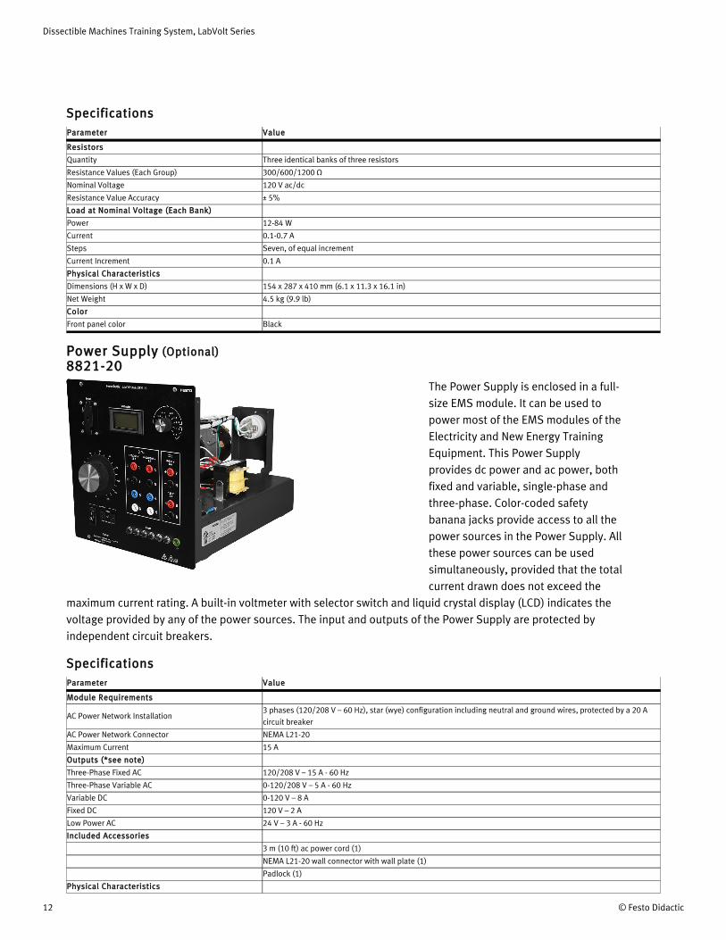
Power Supply (Optional) 8821-20
The Power Supply is enclosed in a full-size EMS module. It can be used to power most of the EMS modules of the Electricity and New Energy Training Equipment. This Power Supply provides dc power and ac power, both fixed and variable, single-phase and three-phase. Color-coded safety banana jacks provide access to all the power sources in the Power Supply. All these power sources can be used simultaneously, provided that the total current drawn does not exceed the
maximum current rating. A built-in voltmeter with selector switch and liquid crystal display (LCD) indicates the voltage provided by any of the power sources. The input and outputs of the Power Supply are protected by independent circuit breakers.
SpecificationsParameter Value
Module Requirements
AC Power Network Installation3 phases (120/208 V – 60 Hz), star (wye) configuration including neutral and ground wires, protected by a 20 A circuit breaker
AC Power Network Connector NEMA L21-20
Maximum Current 15 A
Outputs (*see note)
Three-Phase Fixed AC 120/208 V – 15 A - 60 Hz
Three-Phase Variable AC 0-120/208 V – 5 A - 60 Hz
Variable DC 0-120 V – 8 A
Fixed DC 120 V – 2 A
Low Power AC 24 V – 3 A - 60 Hz
Included Accessories
3 m (10 ft) ac power cord (1)
NEMA L21-20 wall connector with wall plate (1)
Padlock (1)
Physical Characteristics
Dissectible Machines Training System, LabVolt Series
© Festo Didactic 13
Parameter Value
Dimensions (H x W x D) 308 x 287 x 495 mm (12.1 x 11.3 x 19.5 in)
Net Weight 18.4 kg (40.5 lb)
*Note
The Power Supply cannot supply all the amounts of current indicated by the current ratings on its front panel at the same time. The current indicated for the fixed ac three-phase output section can only be obtained if no current is drawn from any other section, because this section is protected by the main circuit breaker common to every section. If currents flow in other sections, the available current for the fixed ac three-phase output section decreases. The variable ac output section and the variable dc output section are protected by a common set of circuit breakers placed after the fixed ac three-phase output section, which means that the current capacity has to be shared between the two sections. For instance, if current of the variable dc output section is at 70% of its nominal value, current drawn from the variable ac output section should not exceed 30% of its nominal value. The fixed dc output section is also protected by circuit breakers placed after the fixed ac three-phase output section.
Connection Lead Set (Optional) 8951-L0This Connection Lead Set consists of extra-flexible leads terminated with stacking 4 mm safety banana plugs. In addition, the set includes stacking 2 mm banana plug leads of the same length and color.
SpecificationsParameter Value
4 mm Safety Banana Plug Leads Characteristics
Cross Section 1 mm² (1974 cmil)
Rated Current 19 A
Rated Voltage 600 V, CAT II
4 mm Safety Banana Plug Leads Quantities
Yellow, 30 cm (12 in) 20
Red, 60 cm (24 in) 10
Blue, 90 cm (36 in) 4
2 mm Safety Banana Plug Leads Characteristics
Cross Section 0.5 mm² (987 cmils)
Rated Current 10 A
Rated Voltage 30 V ac / 60 V dc
2 mm Safety Banana Plug Leads Quantities
Red, 60 cm (24 in) 4
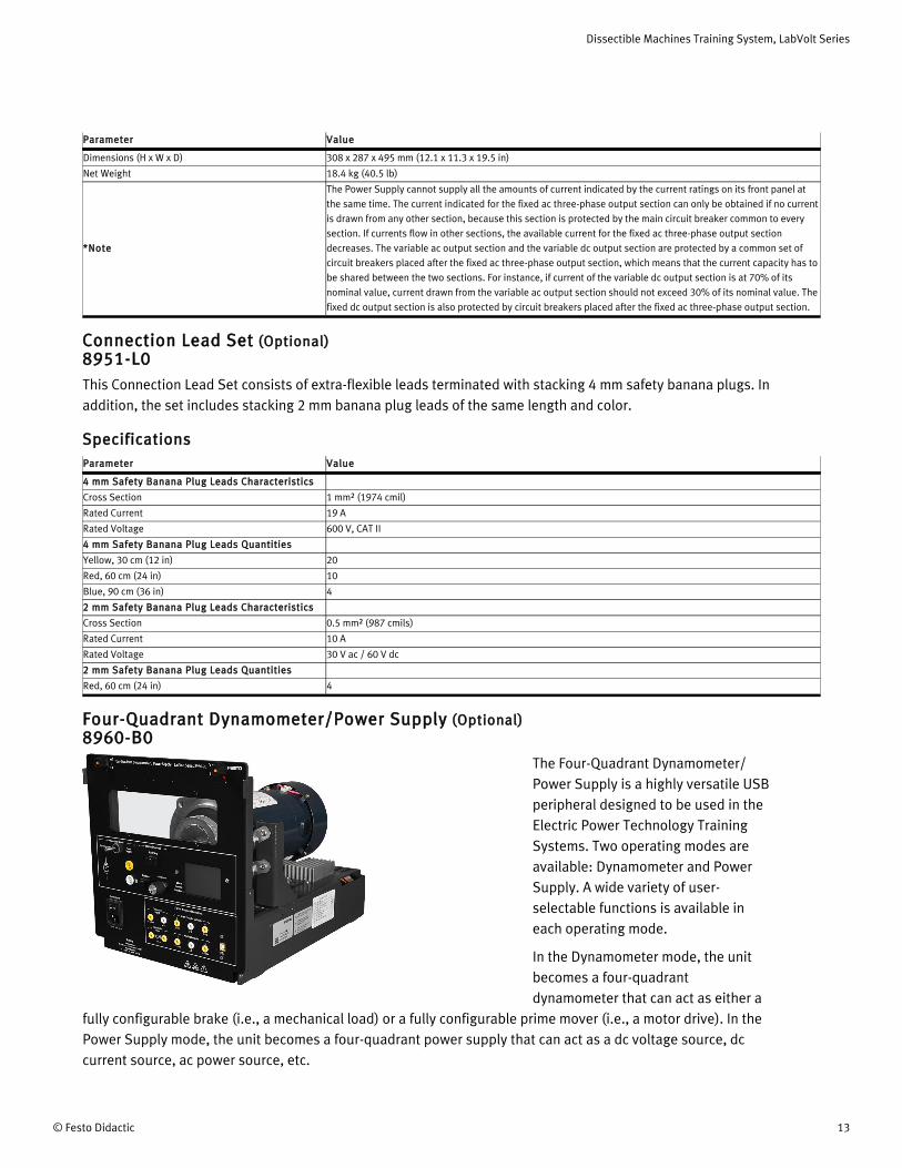
Four-Quadrant Dynamometer/Power Supply (Optional) 8960-B0
The Four-Quadrant Dynamometer/Power Supply is a highly versatile USB peripheral designed to be used in the Electric Power Technology Training Systems. Two operating modes are available: Dynamometer and Power Supply. A wide variety of user-selectable functions is available in each operating mode.
In the Dynamometer mode, the unit becomes a four-quadrant dynamometer that can act as either a
fully configurable brake (i.e., a mechanical load) or a fully configurable prime mover (i.e., a motor drive). In the Power Supply mode, the unit becomes a four-quadrant power supply that can act as a dc voltage source, dc current source, ac power source, etc.
Dissectible Machines Training System, LabVolt Series
14 © Festo Didactic
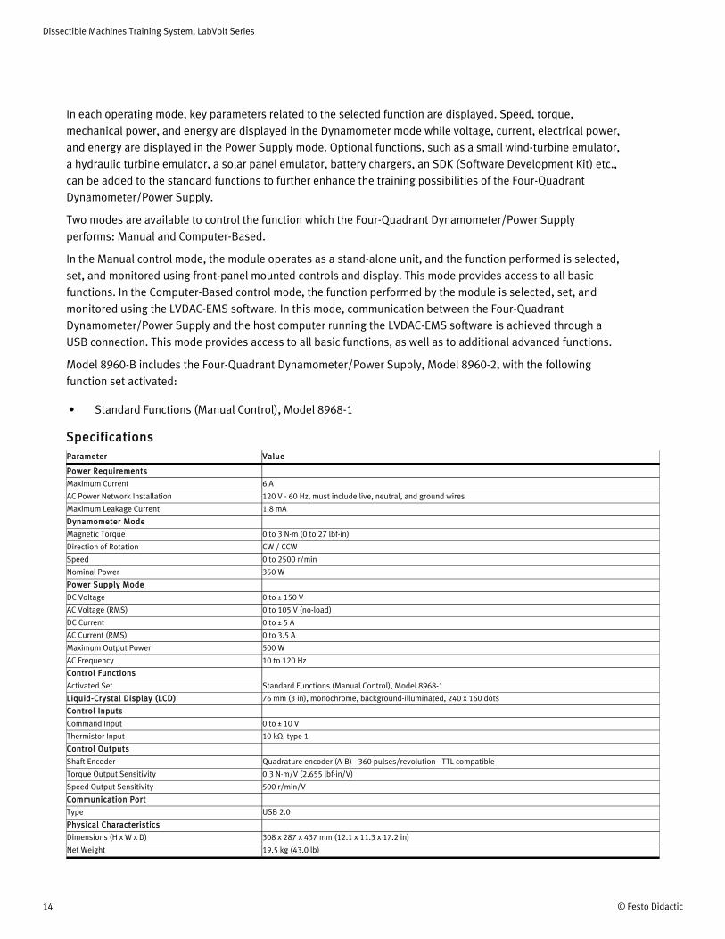
In each operating mode, key parameters related to the selected function are displayed. Speed, torque, mechanical power, and energy are displayed in the Dynamometer mode while voltage, current, electrical power, and energy are displayed in the Power Supply mode. Optional functions, such as a small wind-turbine emulator, a hydraulic turbine emulator, a solar panel emulator, battery chargers, an SDK (Software Development Kit) etc., can be added to the standard functions to further enhance the training possibilities of the Four-Quadrant Dynamometer/Power Supply.
Two modes are available to control the function which the Four-Quadrant Dynamometer/Power Supply performs: Manual and Computer-Based.
In the Manual control mode, the module operates as a stand-alone unit, and the function performed is selected, set, and monitored using front-panel mounted controls and display. This mode provides access to all basic functions. In the Computer-Based control mode, the function performed by the module is selected, set, and monitored using the LVDAC-EMS software. In this mode, communication between the Four-Quadrant Dynamometer/Power Supply and the host computer running the LVDAC-EMS software is achieved through a USB connection. This mode provides access to all basic functions, as well as to additional advanced functions.
Model 8960-B includes the Four-Quadrant Dynamometer/Power Supply, Model 8960-2, with the following function set activated:
• Standard Functions (Manual Control), Model 8968-1
SpecificationsParameter Value
Power Requirements
Maximum Current 6 A
AC Power Network Installation 120 V - 60 Hz, must include live, neutral, and ground wires
Maximum Leakage Current 1.8 mA
Dynamometer Mode
Magnetic Torque 0 to 3 N·m (0 to 27 lbf·in)
Direction of Rotation CW / CCW
Speed 0 to 2500 r/min
Nominal Power 350 W
Power Supply Mode
DC Voltage 0 to ± 150 V
AC Voltage (RMS) 0 to 105 V (no-load)
DC Current 0 to ± 5 A
AC Current (RMS) 0 to 3.5 A
Maximum Output Power 500 W
AC Frequency 10 to 120 Hz
Control Functions
Activated Set Standard Functions (Manual Control), Model 8968-1
Liquid-Crystal Display (LCD) 76 mm (3 in), monochrome, background-illuminated, 240 x 160 dots
Control Inputs
Command Input 0 to ± 10 V
Thermistor Input 10 kΩ, type 1
Control Outputs
Shaft Encoder Quadrature encoder (A-B) - 360 pulses/revolution - TTL compatible
Torque Output Sensitivity 0.3 N·m/V (2.655 lbf·in/V)
Speed Output Sensitivity 500 r/min/V
Communication Port
Type USB 2.0
Physical Characteristics
Dimensions (H x W x D) 308 x 287 x 437 mm (12.1 x 11.3 x 17.2 in)
Net Weight 19.5 kg (43.0 lb)
Dissectible Machines Training System, LabVolt Series
© Festo Didactic 15
12 Refer to the Computer Requirements in the System Specifications section of this datasheet if the computer is to be provided by the end-user. Only one computer is required per station. This model is available in multiple voltage- and frequency dependent variants. Contact a Festo representative to
obtain the correct part number.
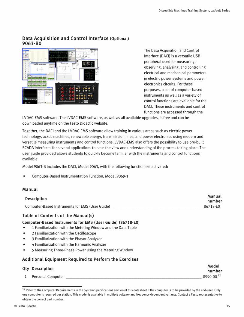
Data Acquisition and Control Interface (Optional) 9063-B0
The Data Acquisition and Control Interface (DACI) is a versatile USB peripheral used for measuring, observing, analyzing, and controlling electrical and mechanical parameters in electric power systems and power electronics circuits. For these purposes, a set of computer-based instruments as well as a variety of control functions are available for the DACI. These instruments and control functions are accessed through the
LVDAC-EMS software. The LVDAC-EMS software, as well as all available upgrades, is free and can be downloaded anytime on the Festo Didactic website.
Together, the DACI and the LVDAC-EMS software allow training in various areas such as electric power technology, ac/dc machines, renewable energy, transmission lines, and power electronics using modern and versatile measuring instruments and control functions. LVDAC-EMS also offers the possibility to use pre-built SCADA interfaces for several applications to ease the view and understanding of the process taking place. The user guide provided allows students to quickly become familiar with the instruments and control functions available.
Model 9063-B includes the DACI, Model 9063, with the following function set activated:
• Computer-Based Instrumentation Function, Model 9069-1
Manual
DescriptionManual number
Computer-Based Instruments for EMS (User Guide) _____________________________________________ 86718-E0
Table of Contents of the Manual(s)
Computer-Based Instruments for EMS (User Guide) (86718-E0)• 1 Familiarization with the Metering Window and the Data Table• 2 Familiarization with the Oscilloscope• 3 Familiarization with the Phasor Analyzer• 4 Familiarization with the Harmonic Analyzer• 5 Measuring Three-Phase Power Using the Metering Window
Additional Equipment Required to Perform the Exercises
Qty DescriptionModel number
1 Personal Computer ____________________________________________________________________ 8990-00 12

Dissectible Machines Training System, LabVolt Series
16 © Festo Didactic
13 Required if power is not supplied by the Power Supply, Model 8821-2. This model is available in multiple voltage- and frequency dependent variants. Contact a Festo representative to obtain the correct part number.
Qty DescriptionModel number
1 24 V AC Power Supply _________________________________________________________________ 30004-20
SpecificationsParameter Value
Insulated Voltage Inputs (4)
Range (Low / High Scales) -80 to +80 V / -800 to + 800 V (user-selectable through software)
Impedance (Low / High Scales) 326.6 kΩ / 3.25 MΩ
Bandwidth DC to 65 kHz (-3 dB)
Accuracy 1% (dc to 10 kHz)
Insulation 800 V
Maximum Voltage (Any Terminal vs GND) 283 V ac / 400 V dc
Measurement Category CAT II (283 V ac/400 V dc versus ground)
Insulated Current Inputs (4)
Range (Low / High Scales) -4 to +4 A / -40 to + 40 A (25 A rms)
Impedance (Low / High Scales) 5 mΩ / 50 mΩ
Bandwidth DC to 65 kHz (-3 dB)
Accuracy 1% (dc to 10 kHz)
Insulation 800 V
Maximum Voltage (Any Terminal vs GND) 283 V ac / 400 V dc
Measurement Category CAT II (283 V ac/400 V dc versus ground)
Analog Inputs (8)
Voltage Range -10 to +10 V
Impedance > 10 MΩ
Bandwidth DC to 125 kHz
Measured Parameters User-selectable through software
Parameter-to-Voltage Ratio User-determined through software
A/D Converter for Insulated and Analog Inputs (16)
Type Successive approximation
Resolution 12 bits
Integral Non-Linearity ≤ ±1.5 LSB
Differential Non-Linearity ≤ ±1 LSB
Maximum Sampling Rate 600 ksamples/s (one channel)
FIFO Buffer Size 16 ksamples
Analog Outputs (2)
Voltage Range -10 to +10 V
Operational Load Impedance > 600 Ω
D/A Converter for Analog Outputs (2)
Type Resistor string
Resolution 12 bits
Integral Non-Linearity ≤ ±8 LSB
Differential Non-Linearity -0.5 to +0.7 LSB
Digital Inputs (3)
Types Encoder (2), synchronization (1)
Signal Level 0-5 V (TTL compatible)
Maximum Input Frequency 50 kHz
Impedance 5 kΩ
Digital Outputs (9)
Types Control (6 on a DB9 connector and 2 on 2 mm banana jacks), synchronization (1 on a DB9 connector)
Signal Level 0-5 V (TTL compatible)
Maximum Output Frequency 20 kHz (software-limited)
Impedance 200 Ω
Control Functions
Activated Set Computer-Based Instrumentation Function, Model 9069-1
Computer I/O Interface USB 2.0 full speed via type-B receptacle
Power Requirements 24 V - 0.4 A - 50/60 Hz
13
Dissectible Machines Training System, LabVolt Series
© Festo Didactic 17
Parameter Value
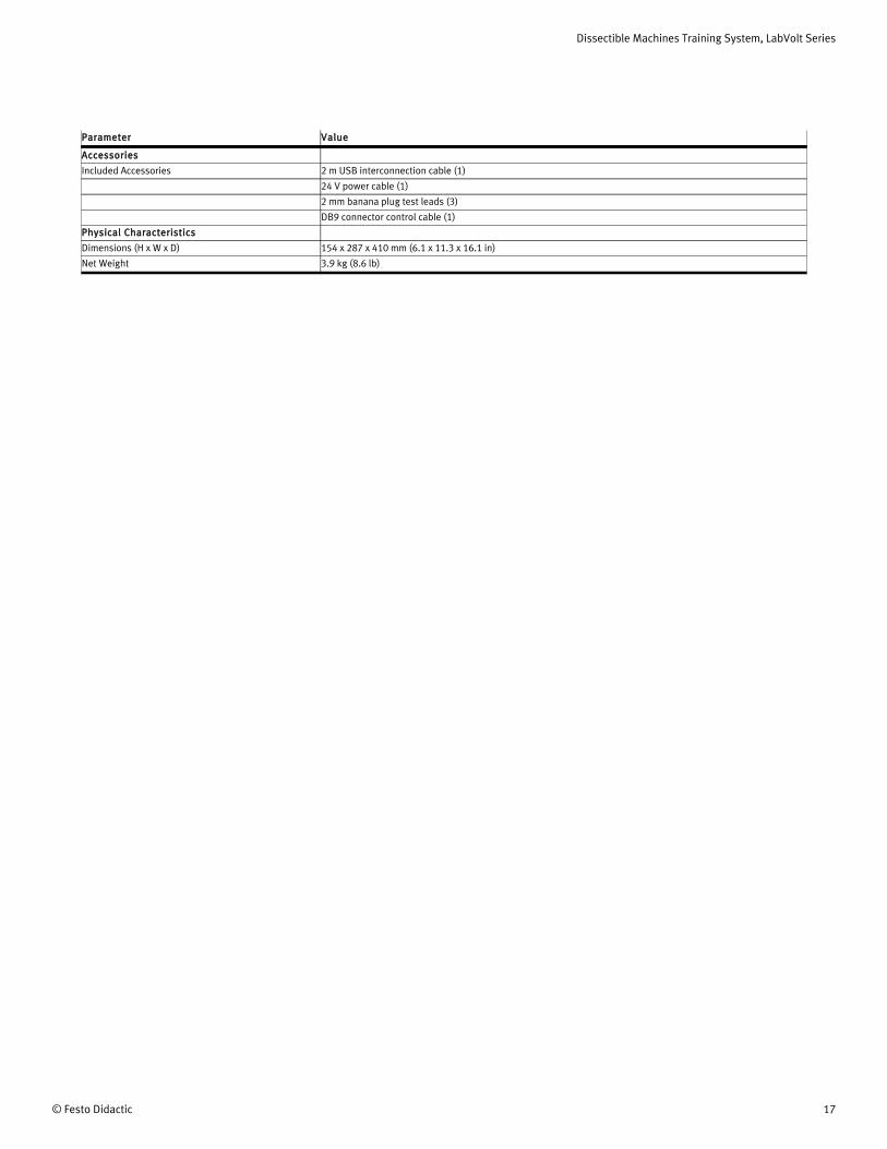
Accessories
Included Accessories 2 m USB interconnection cable (1)
24 V power cable (1)
2 mm banana plug test leads (3)
DB9 connector control cable (1)
Physical Characteristics
Dimensions (H x W x D) 154 x 287 x 410 mm (6.1 x 11.3 x 16.1 in)
Net Weight 3.9 kg (8.6 lb)
Dissectible Machines Training System, LabVolt Series
18 © Festo Didactic
Reflecting the commitment of Festo Didactic to high quality standards in product, design, development, production, installation, and service, our manufacturing and distribution facility has received the ISO 9001 certification.
Festo Didactic reserves the right to make product improvements at any time and without notice and is not responsible for typographical errors. Festo Didactic recognizes all product names used herein as trademarks or registered trademarks of their respective holders. © Festo Didactic Inc. 2018. All rights reserved.
Festo Didactic SE
Rechbergstrasse 373770 DenkendorfGermany
P. +49(0)711/3467-0F. +49(0)711/347-54-88500
Festo Didactic Inc.
607 Industrial Way WestEatontown, NJ 07724United States
P. +1-732-938-2000F. +1-732-774-8573
Festo Didactic Ltée/Ltd
675 rue du CarboneQuébec QC G2N 2K7Canada
P. +1-418-849-1000F. +1-418-849-1666
www.labvolt.com
www.festo-didactic.com