Embed Size (px)
Citation preview
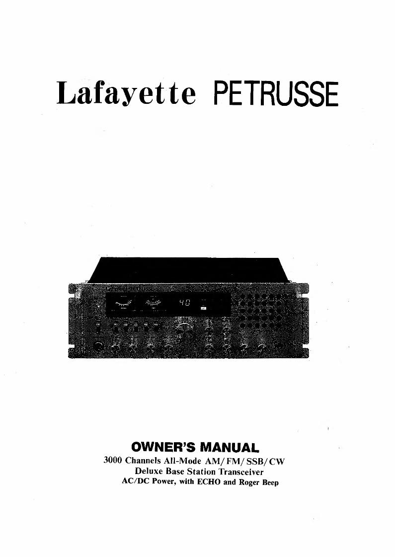
L a fa y e t te PETRUSSE
OWNER’S MANUAL3000 Channels АН-Mode A M /F M /SS B /C W
Deluxe Base Station Transceiver AC/DC Power, with ECHO and Roger Веер

TABLE OF CONTENTS
PageSection 1: Spécifications.................................................................................................................................................................... 1Section 2: Installation................................................................................................................................................. 2
Location/Connection............. i .................................................................................................................................................... 2Noise Interférence............................................................................ 2Antennas........................................................................................................................................ 2Remote Speaker.............................................................................................................................................................................2Public Address................................................................................................................................................................................2
Section 3: Operation.........................................................................................................................................................................3Control Functions.................................... 4Rear Panel Connectors................................................................................................................................................................ 5Operating Procedure То Receive.................................................................................................................... 6Operating Procedure То T ransm it............................................................................................................................................ 6Public Address Operation................................................................................... 6SWR Measurement. ........................................................................ 6
Section 4: Maintenance & Adjustment......................... 7Circuit Theory.......................................................... 7Alignment Procedure................................................................................................................ . . . . . . . . ................................ 8Frequency/Channel C h a rt................................... 11PC Board Layout......................... 12Schematic Diagram...................................... 15Replacement Part L is t ................................................................................................................................................................. 16
Section 1 SpécificationThank you for your confidence in selecting Lafayette two- way radio equipment. We know you'll find your transceiver as exciting as it is practical. Many years of valuable expérience designing electronic products are behind our two- way communications sytstems. Only the highest quality components are incorporated into Lafayette radios to assure reliability and maximum performance.
Installing and operating the Lafayette is not complicated, but the fiexib ility provided by its numerous operating features may not be fu liy appreciated until a little time is spent becoming familiar with its Controls and connections.It will be to your advantage to save all the packing matériels -cartons, fi Ilers, cushoning, etc., they w ill prove valuable in preventing damage should you ever hâve occasion to transport or ship the Lafayette.
Spécifications
General ReceiverChannels 3000 Channels AM Sensitivity 1 mV for 10 dB S/NModulation Modes CW, FM, AM, USB, LSB FM Sensitivity 1 mV for 20 dB S/NFrequency Range 26.065 to 28.305 MHz SSB Sensitivity 0.2 mV for 10 dB S/NFrequency Control Phase-Iocked Synthesizer AM/FM Selectivity 5 dB at 4 kHz, 50 dB at 10 kHzFrequency Tolérance ±0.005% SSB Selectivity 5 dB at 2 kHzFrequency Stability ±0.003% Image Rejection Morethan 50 dBOperating Température -30°X to + 50° C IF Rejection Morethan 80 dB at 455 kHzRange AGC Change in audio output lessMicrophone Plug-in [4-pin] ,600 Ohm than 12 dB: from IOm.V to 0.4V
dynamie type Squelch Adjustable -threshold less thanAC input Voltage 220V 60Hz 0.7 mVDC Input Voltage 13.8 V Audio Frequency 400 to 2,500 HzAC Power Consumption 75W ResponseAntenna Connectors Standard SO-239 type X2 Oistortion Less than 10% at 2 watts output[A and B] Semiconductors 9 IC, 1 FETs, 43 Transistors
Adjacent Channel
into 8 Ohms
Meter #1 Indicates relative RF power >75 dBoutput/antenna SWR Indicates received signal strength
Rejection Cross Modulation >50 dBMeter# 2Intermediate Frequency 10.695 MHz [Am-1st, SSB],
Transmitter 455 KHz [AM-2nd]Power Output Low 0.5-AM 0.5-FM 3-SSB(W) Clarifier Range ±5 KHz
Normal 5-AM5-FM 12-SSB(W) Noise blanker IF singlegate typeSSB Generation Dual-balanced modulation Audio Output Power More than 3 watts into 8 OhmsAM Modulation Class B amplitude, coliectors Built-in Speaker 8 Ohms, dynamie
modulation Externai Speaker Disables internal speaker whenAM Modulation Up to 100% (optional) connectedCapability FM Deviation ±1,5 KHz @ 1,250 Hz 20 mV
audioClarifier Range ±5 KHzFfarmonic and Spurious Emission
Betterthan60 dB
AM/FM Frequency 40.0 to 5,000 HzResponse SSB Frequency 400 to 3,000 HzResponseOutput Impédance 50 Ohms unbalanced X2[A and В]Output Indicators RF Meter shows relative RF
output power.
- 1 -
Section 2 InstallationLocation/ConnectionThe transceiver should be placed in a convenient operating location close to an AC power outlet and the antenna lead- in cable (s).
The transceiver is attached with the AC power cord set. Proceed as follows to complété ail necessary connections to the transceiver.
1 ) Your transceiver has two standard antenna connectors of type SO-239 both located on rear panel, for easy connection to standard PL-259 coax plugs. If the coax antenna cable must be made longer, use coax cable with impédance of 50 ohms, frequency ratings for 27 MHz, and use only enough cable to suit your needs. This wili insure a proper impédance match and maximum power transfer from the transmitter to the antenna.2) AC Power Operation : Use 110 or 220 volts AC power for the base station.
Noise InterférenceThere are- several kinds ot noise interfering you may en- counter in base station operation. Some of these noise sources are; fluorescent buzz, nearby commercial broad- cast, electrical appliance, lawnmower, and electrical storms, etc. Commercial products are available to reduce interférence from these sources. Consult your dealer or СВ/ amateur radio supply shops.
Antennas
For best transmission and réception, your CB transceiver should use an antenna especiaüy designed for a frequency of 27 MHz. Antennas are purchased separately and include installation instructions. Numerous types of CB antennas are available that range from emphasis on ease of installation to emphasis on performance. Often the différence in performance between many of the antenna is modest. Your can connect 2 antennas to your CB, or 1 antenna and 1 dummy load. v v
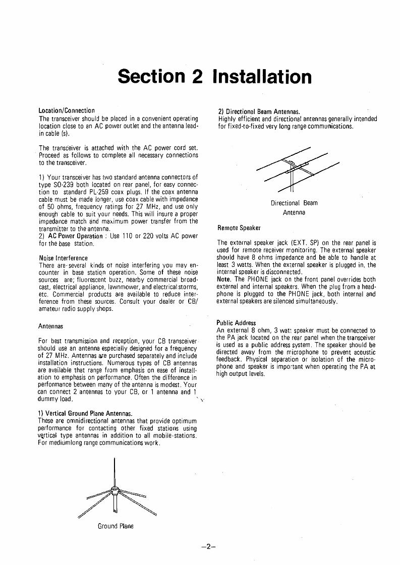
1) Vertical Ground Plane Antennas.These are omnidirectionai antennas that provide optimum performance for contacting other fixed stations using vertical type antennas in addition to ail mobile-stations. For mediumlong range communications work.
2) Directional Beam Antennas.Highly efficient and directional antennas generally intended for fîxed-to-fixed very long range communications.
Directional Beam Antenna
Remote Speaker
The external speaker jack (EXT. SP) on the rear panel is used for remote receiver monitoring. The external speaker should hâve 8 ohms impédance and be able to handle at least 3 watts. When the external speaker is piugged in, the internai speaker is disconnected.Note. The PHONE jack on the front panel overrides both external and internai speakers. When the plug from a head- phone is piugged to the PHONE jack, both internai and external speakers are silenced simultaneously.
Public AddressAn external 8 ohm, 3 watt speaker must be connected to the PA jack located on the rear panel when the transceiver is used as a public address system. The speaker should be directed away from the microphone to prevent acoustic feedback. Physical séparation or isolation of the microphone and speaker is important when operating the PA at high output levels.
- 2 -
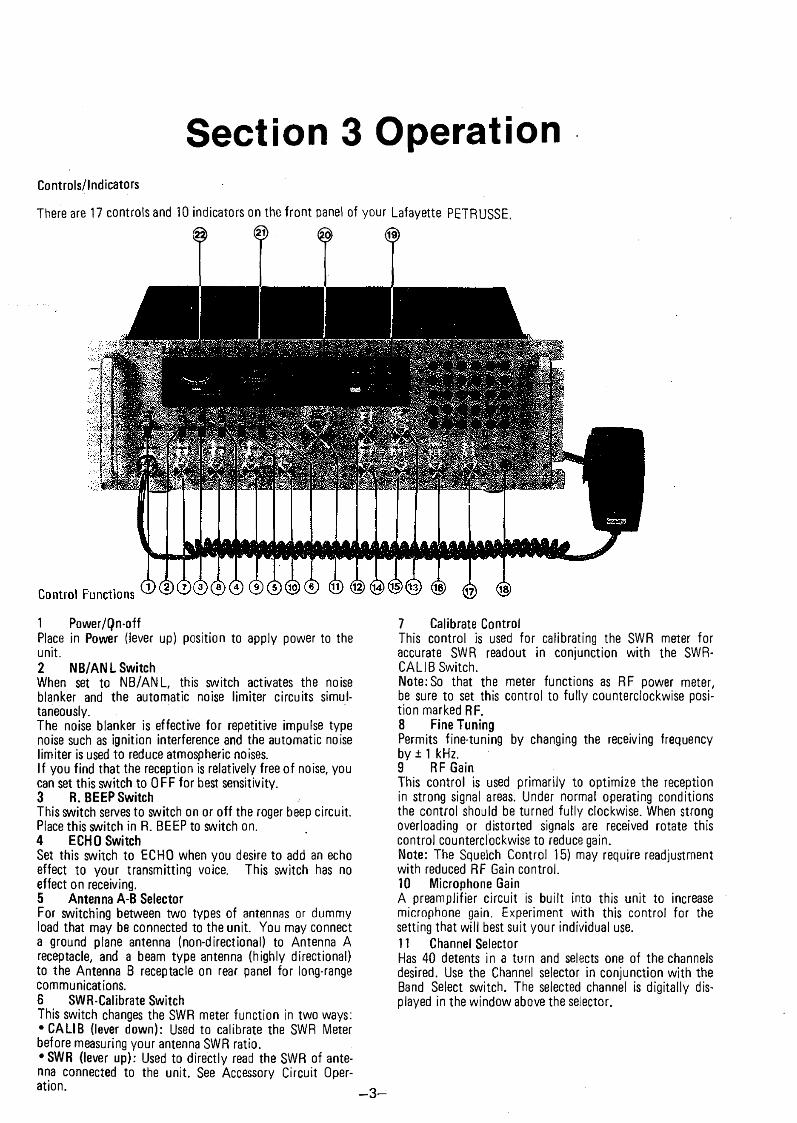
Section 3 OperationControls/lndicators
There are 17 Controls and 10 indicators on the front panel of your Lafayette PETRUSSE.© @ <© ©
1 Power/Qn-offPlace in Power (lever up) position to apply power to the unit.2 NB/ANL SwitchWhen set to NB/ANL, this switch activâtes the noise blanker and the automatic noise limiter circuits simui- taneously.The noise blanker is effective for répétitive impulse type noise such as ignition interférence and the automatic noise limiter is used to reduce atmospheric noises.If you find that the réception is reîatively free of noise, you can set this switch to OFF for best sensitivity.3 R. ВЕЕР SwitchThis switch serves to switch on or o ff the roger beep circuit. Place this switch in R. ВЕЕР to switch on.4 ECHO SwitchSet this switch to ECHO when you desire to add an echo effect to your transmitting voice. This switch has no effect on receiving.5 Antenna A-В SelectorFor switchîng between two types of antennas or dummy load that may be connected to the unit. You may connect a ground plane antenna (non-directional) to Antenna A réceptacle, and a beam type antenna (highly directions!) to the Antenna B réceptacle on rear panel for long-rangé communications.6 SWR-Calibrate SwitchThis switch changes the SWR meter function in two ways: •C ALIB (lever down): Used to calibrate the SWR Meter before measuring your antenna SWR ratio.• SWR (lever up): Used to directly read the SWR of antenna connected to the unit. See Accessory Circuit Operation.
7 Calibrate ControlThis control is used for caiibrating the SWR meter foraccurate SWR readout in conjunction with the SWR- CALIB Switch.Note:So that the meter functions as RF power meter, be sure to set this control to fu lly countercîockwise position marked RF.8 Fine TuningPermits fine-tuning by changing the receiving frequency by ± 1 kHz.9 RF GainThis control is used primarily to optimize the réception in strong signal areas. Under normal operating conditions the control should be turned fu lly clockwise. When strong overloading or distorted signais are received rotate this control countercîockwise to reduce gain.Note: The Squelch Control 15) may require readjustment with reduced RF Gain control.10 Microphone GainA preamplifier circuit is built into this unit to increase microphone gain. Experiment with this control for the setting that will best suit your individual use.11 Channel SelectorHas 40 detents in a turn and selects one of the channels desired. Use the Channel selector in conjunction with the Band Select switch. The seiected channel is digitally dis- played in the window above the selector.
- 3 -
12 Mode SelectorSelects the mode of operation in either CW, standard FM, AM or USB and LSB. Transmissions in any mode can only be commnnicated to .stations operating in the same mode.13 RF POWER Switch HI-MID-LOSet this switch to the position that selects the RF power output you want in AM or FM transmission.14 Band Select SwitchUsed with the channel selector. Selects one of 5 bands of 40 frequencies.. See back cover to page 11 for information of channel provision and frequencies,15 SquelchThis control is used to eut off or eliminate receiver back- ground noise in the absence of an incoming signal. For maximum receiver sensitivity it is desired that the contro! be adjusted only to the point where the receiver back- ground noise or ambient background noise is eiiminated. Turn fu lly counterclockwise then slowly clockwise until the receiver noise just disappears. Any signal to be received must now be sîightly stronger than the average received noise. Further clockwise rotation will increase the threshold level which a signal must overcome in order to be heard. Only strong signais will be heard at a maximum clockwise setting.16 AF GainPermits you to adjust the listening level when receiving.17 VFOOpérâtes on both TX and RX modes (±5kHz), ailowing you to use the inter-channel space. Especially useful in SSB.18 Phone JackAccepts a plug from a headset of 4 to 32 Ohm impédance, insertion of the plug will silence the built in speaker (and external speaker connected to External Speaker jack).19 Function IndicatorsLED indicators located in the LED area permit you to know instantly the mode to which the unit is engaged. On Air: Lîghts up during transmit mode indicaîing you are on-the-air.CW-FM-AM-USB-LSB: Indicates a corresponding mode selected by the Mode selector 12).20 Channel ReadoutThis is the LED [light emitting diode] digital readout to indicate the channel selected by the Channel selector.
21 Power/SWR MeterUsed for two purpose - to indicate relative transmitter power when transmitting and to indicate antenna SWR [standing wave ra tio ]. Note that the power meter has separate scales for AM (FM) and SSB (CW) transmission, respectively.22 S [Signal] MeterThe left hand meter provides a relative indication of the signal strength of a received signai in S units during réception. Note that SSB signais will respond this meter only during voice modulation. This being due to the fact that SSB transmissions do not contain a continuous RF carrier as is found on AM or FM and CW.23 Push-to-Talk MicrophoneThe receiver and transmitter are controlled by the Push-to- Talk switch on the microphone. Press the switch and the transmitter is activated; release the switch to reçoive. When transmitting, hold the microphone two inches from the mouth and speak clearly in a normal voice. The radio cornes complété with the low impédance dynamie microphone (supplied). Note: Depressing the Push-to-Talk switch on the microphone is also required to activate the PA system.
—4 —
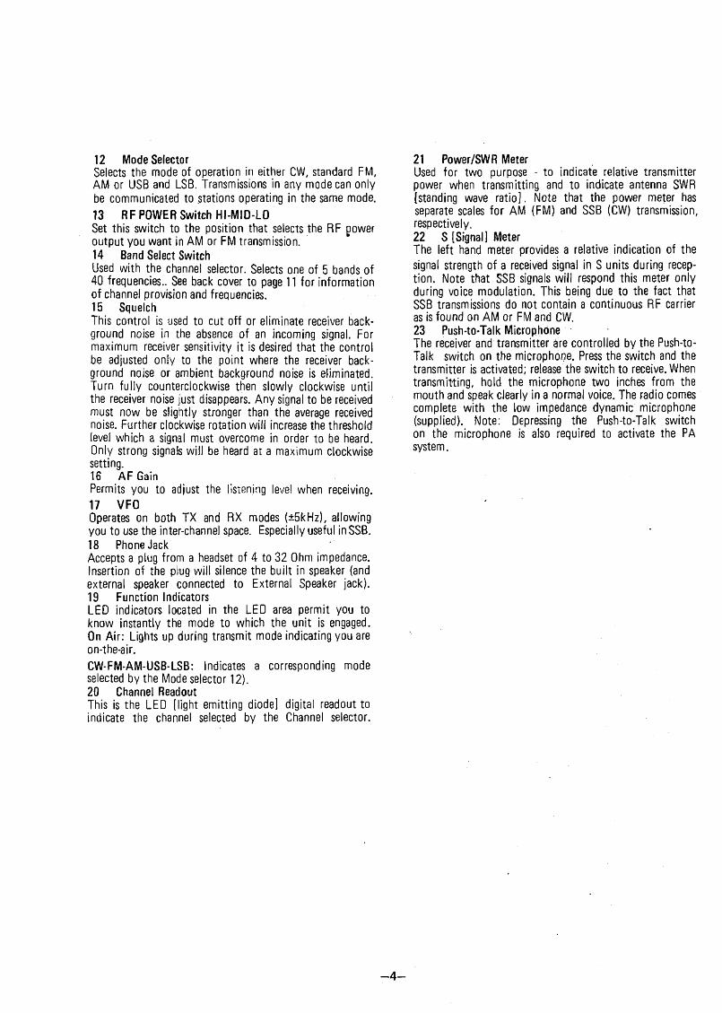
Rear Panel
TO M fVIKT TJ*t C l SH3CX W « 0 со KOT ню ш 1KI5 A W JM C t TO KAW Ot «CISTOM. С;Ш№М.ГС m v lN Î ItiC n iC A l, 1МЗ£к, 00 «от tt«QV$ ТJA trt *31TS« COVf.H МЭ U îf* î f lV IC U IH лиг* wmt. mut ***vicr« то Q U 4 i? W 9 m s o * w t Ii 1,
Rear Panel Conneotors
1 Antenna Réceptacle A/BAccept PL-259 type coaxial plugs from antenna system. Switching to connect the transceiver output to either réceptacle is done with the Antenna A-В switch on the front panel.2 PA Speaker JackUsed for public address operation. The PA speaker should be connected to thisr jack using 1/8" (3.6mm) diameter plug. Insertion* of an external speaker into the External Speaker jack will not interrupt the PA operation.3 External Speaker JackUsed to connect an external speaker for extra sound source. Use 1/8" (3.6mm) diameter plug for connection. Insertion of the plug into this jack will silence the internai speaker.4 CW KeyUse for morse code operation. Connect a CW key to this jack and place the CW/FM/AM/USB/LSB switch in the CW position.5 DC Power Socket12 Volt OC power for the unit is fed through this socket using the DC power cable supplied. Do not force the DC power cable into the socket sińce the socket pins are unevenly spaced allowing only one way insertion.6 Sélective Call JackA provision has been made which enables your transceiver to couple with a sélective call set (availabîe from your dealer). This jack is used to connect the sélective call set to the unit, and is normally occupied with a plug prewired for normal CB operation, Do not remove the plug unless you are using the jack. Following the deâler's advise and instruction manuał accompanying the purchased sélective call set will ensure proper sélective call installation and operation.
© © © ® ©
7 FuseAccomodates a fuse for AC input circuit protection. Use 250V 1A fuse for replacement.Note. Before replacing the fuse, see your dealer to che.ck to find out the reason why the fuse was biow. Replacing without check may only blow the fuse again.8 AC Power CordConnects to AC power outlet for AC mains supply.9 Frequency Counter Output JackThe RCA-type (pin) jack is used to connect an optional frequency counter so that you can watch channel frequency digitally. The frequency counter readout will be possible on transmitting only.10 Recording Output JackThe RCA-type (pin) jack provides output for connection to a tape recorder to permit recording of received signais or your modulating voice.
IMPO RTANT: Make sure that the antenna, power source, and microphone are connected before you operate.1 ) Set the CB-РА switch to CB position.2} Turn the unit on by setting the Power Switch to On position. Now the meters, Channel Indicator, and Function Indicators will be iliuminated.
:3) Temporarily, set the Mode Switch in AM position.4) Set the Squelch Control in fu lly counterclockwise position and ajust the AF Gain control for a comfortable listening ievel.5) Listen to the background noise from the speaker. Turn the Squelch Control slowly clockwise until the noise just disappears (no signai should be present). Leave the Squelch Control at this setting. The Squelch Control is now pro- perly adjusted. The receiver will remaän quiet until a singal is actualy received. Do not advance the Squelch Control too far clockwise or some of the weaker signais will not be heard.6) Depress the Clarifier and set it to the center (12 o'clock) position.7) Select a desi.red mode of operation, CW, FM, AM, USB or LSB and adjust the Clarifier.8) Select a channeî you desire by the Band Select switch, then by the Channel Selector.Note. If you want to operate in between channels, puli out the clarifier knob and rotate it upscale or downscale. (This also affects in transmitting mode.)
Operating Procedure To Transmit1) Select the desired channel and mode of transmission.2) If the channel is elear, depress the Push-to-Talk switch on the microphone. Speak in a normal tone of voice. Standby-BeepA special provision has been built in you radio to give other stations a sign which tells that you are turning to receive. Without needing switching operation to activate this feature, a been tone is automatically transmitted at each time you release the push-to-talk switch on the microphone to turn to receive mode.Microphone gain controlA preamplifier circuit is built into the radio to increase the microphone gain. Experiment with the control for setting that will best suit your individual use.Note. When the microphone gain control is set to maximum, ambient noise may also be picked up by the microphone. In high noise situations, low microphone gain setting may produce the best results.The microphone gain control is also used to adjust PA loudness.
Operating Procedure To Receive
To use this feature of the transceiver, a speaker having a voice coil impédance of 8 to 16 ohms and a power handling capability of at least 3 watts should be connected ta the PA SP jack on the rear panel. Be sure that there is physical séparation between the microphone and the PA speaker itself. If the PA speaker is located very close to the microphone, acoustic feedback will resuit when the PA amplifier ■is operated at high volume (or when PA is used indoors). Adjustment of PA volume is made with the MIC GAIN control.
SWR Measurement
Most antennas are factory tuned, but the antenna efficiency may be peaked by slightly adjusting the length of antenna using the SWR meter built into the unit. This adjustment may improve the antenna standing wave ratio (SWR). The SWR permits you to détermine how well matched the antenna and its cables are to your transceiver.1) Set the unit in the receive mode as instructed under the Operating Procedure to Receive section.2) Set the Mode switch to AM position; the SWR-Cal 6) switch to the Cal position.3) Press the Push-to-Talk switch on the microphone and turn the Calibrate Contro! clockwise (past dick) so that the SWR meter pointer exactly coïncides with the Set mark on the scale. Release the Push-to-Talk switch.4) Set the SWR-Cal switch to the SWR position and depress the Push-to-Talk switch again. The SWR of your antenna is read directly on the scale.Note: An SWR below 2 or less is desired as this indicates that over 95% of the transmitted power is broadcast into the air.
Public Address Operation
- 6 -
Section 4 Maintenance & AdjustmentCircuit Theory ,
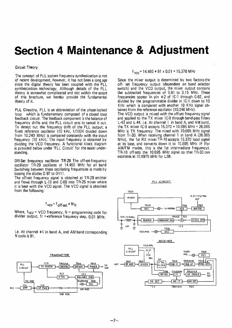
The concept of PLL system frequency synthesization is not of recent development, however, it has not been a long âge since the digital theory has been coupled with the PLL synthesization; technology. Aithough details of the PLL theory is-somewhat complicated and riot within the scope of this brochure, we hereby provide the fundamental theory of it.
PLL Circuitry. PLL is an abbreviation of the phase-locked ioop which is fundamentary composed of a closed loop feedback circuit. The feedback component is the balance of frequency drifts and the PLL circuit acts to cancel it out. То detect out the frequency drift of the PLL output, a fîxed reference oscillator (10 kHz, 1/1024 divided down from 10.240 MHz) is compared constantly with the input frequency (10 kHz).'The input frequency is obtained by dividing the VCO frequency. A functional block diagram is provided below ander 'PLL Circuit' for the easier under- standing.
Off-Set frequency oscillator TR-29 The off-set-frequency oscillator' TR-29 oscillâtes at 14.460 MHz for ail band Switching bejween these oscillating frequencies is made by biasing the diodes D 97 to D111.The off-set frequency signal is obtained at TR-29 emitter and flows through L-16 and C-88 into TR-25 mixer where it is beat w ith the VCO signal. The VCO signal is obtained from the following:
f vco ̂off-set+ Nfr
Where, f Vco = VCO frequency, N - programming code for divider output, f r =<eference frequency step, 0.01 MHz.
i.e. A t channel #1 in band A, and AM band corresponding N code is 91.
TRANSMITTER
PLICIRCUIT
FM MOO1C6
MIC ДМР
IC 9 TR 65/66 TR66 TR63TX M IX E R 1— I DRlVERsTH DRIVES 1— fP O W E R '
_ ,— L.C.6......J -------- F PW R>
TXOUTFL3
X'TAL
-TRS1-
IC3BALANCE MOD
SSB MOD.
10.6975MHz TR30Hflh-Г ose
ж — ITR30 I
ose HAM MOD.
f vco = 14.460 +91 X 0.01 = 15.370 MHz
Since the mixer output is determined by two factors-the off- set frequency output (dependent on band selector switch) and the VCO output, the mixer output contains the subtracted frequencies of 0.91. to 3.15 MHz. These frequencies appear’ in pin #2 of IC-1 through C-82, and divided by the progrrammable divider in IC-1 down to 10 KHz which is compared with another 10 K Hz signal obtained from the reference oscillator (10.240 MHz).The VCO output is mixed with the off-set frequency signal and applied to the TX mixer IC-9 through band-pass filters L-43 and 1-44. i.e. At channel 1 in band A, and AM band, the TX mixer IC-9 accepts 15.370 + 10.695 M Hz = 26.065 MHz is TX frequency. The mised with 10.695 MHz signai from Tr-30. When receiving channel 1 in band A (26.065 MHz), the Ist RX mixerTR-18accepts 15.370 local signal at its base, and converts down it to 10.695 MHz IF (for AM/FM modes, this is the 1 st intermediate frequency). TR-18 off-sets the 10.695 MHz signal so that TR-30 сап oscillâtes at 10.6975 MHz for LSB.
PLL circuit
TR25MIXER
15.37-17.61 MHz OUT
TR 29 TR26 TR27OSC I---Ißt— 19Л60М№ 1 VCO I--- [ bÜFFER 1
0 .9 l-3 . l5 M H z
15 LPF JPHASE ] SET
BUFFER I------1 PROGRAM OIV.|------ H X > - ---------|1 /Ю 2б CIV|
TR26 I С 510.26MHz —Ч0|—I ose
RECEIVER
PLLC IR C U IT
10.26 MHz
15.37I17.61MHz
ANTTRl7 TRI8 __RF AMP h-f MIXER
10.695 TR30МНг нам OSC~
XFp i l - HSSB IF m SSB IF H —(PROD DÉrh
TR19 TR20/21 /22 TRlS
ITR8 CF655KHZ TR62/1C8 AM MIX |—|~CF 4 AF POWER SPOUT
Cf FM PET“Tel
j AM 1F j----1AM DET [TR9/10/11 TR23
7
Alignment Procedure
1 - Measurement Condition(1) Reference température_____________ ,25°C(2) Reference humidity________________ 65%Note: Unless otherwise specified, alignment may be perfor- med under the room température of 5 ° - 35° C and the room humidity of 45 - 80%.3) Power supply______________ AC 110V or 220V ±3%
2 - Test Equipment. All test equipment should be properly calibrated.a) 50 Ohms résistive antenna load, 20W.b) Frequency counter operable in the required frequency
range.c) HF signal generator operable over 50 kHz to 60 MHz.d) Synchroschope, 0-100 MHz, high input Z.e) FM déviation meter.f) Digital Voltmeterg) 8 Ohms 5W résistive speaker load.h) Two audio signal generators, 10 Hz to 20 kHz, atténu
ative.i) .RF Wattmeter, 50 ohm/15 watt, thermocoupled.j) Circuit tester, input impédance 20 kOhm/V.k) Regulated DC power supply, more than 4A.l) Dummy microphone plugs, receiveand transmit mode.m) VTVM, 0.1 mV measurabie.
3 - PLL Circuit AlignmentA. [10.24 MHz] Reference Frequency Adjustment
(Check)1) Connect ferquency counter to pin terminal be-
tween C-78 and C-79.2} Check counter reads 10.24000 MHz.3) Tolérance within ±200 Hz is acceptable. Other
wise, replace X-1 (10.24 MHz).
B. [10.695/10.6925/10.6975 MHz] Adjustment.1 ) Connect frequency counter to TP-6.2) 10.695 MHz: Set the mode selector to CW. Adjust
L-26 to 10.695 MHz + 0 ,-1 0 0 Hz.3) 10.6925 MHz: Reset Mode Selector to USB.
Adjust L-27 to 10.6925 MHz, + 0, -1 0 0 Hz.4) 10.6975 MHz: Reset Mode Selector to LSB.
Adjust L-28 to 10.6975 MHz, + 0, -100 Hz.
C. PLL Input Level Adjustment1) Set the mode selector to AM, and the clarifier
Control to center, and set the band selector to Position C of CH 19.
2) Connect synchroscope to TP-4 (pin terminal between the C-82 anu R-107).
3) Adjust L-16 for maximum RF output.
D. [VC0] Adjustment1) Set the mode selector to AM, and the clarifier
control to center, and set the band selector to position E with CH 40.
2) Connect synchroscope to TP-3.
3} Adjust L-18 for maximum RF output.4} Connect DC Voltmeter to TP-2 .(pin termin
between the R-109 and R-258 from IC-5).5) Adjust L-17 to DC 5.0+ 0.1 V.6) Check A band of CH7, must be DC 1.5V minimur
E. [Off -set Frequency] Adjustment >■1) Connect frequency counter to TP-3 (pin termin
of L-18).2) Set the Mode Selector to AM, and the Clarifi
Control to center.3) Set the Band Selector to position C of CH14) Adjust L-19 for 16,040 MHz ±50 Hz.5) Set the mode Selector to USB.6) Adjust L-20 for 16.0425 MHz±50 Hz.7) Set the mode Selector to LSB.8) Adjust L-21 for 16.0375 MHz±50 Hz.9) Set the mode Selector to LSB. and transmit
station.10) Adjust VR-15 for 16.0375 MHz ±50 Hz.
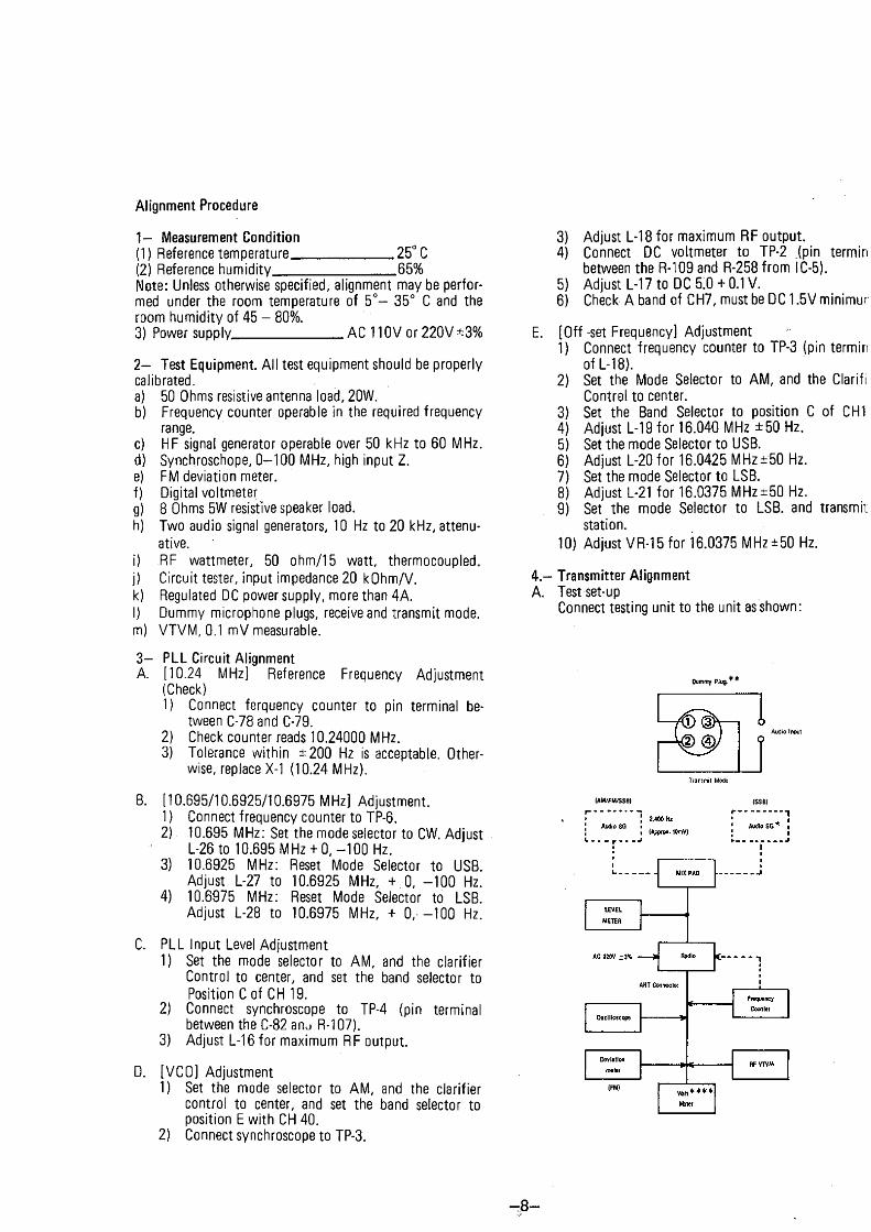
4 . - Transmitter AlignmentA. Testset-up
Connect testing unit to the unit as shown:
Dummy Rlug.**
А1Л1О Input
(АМ/ЛД/&В) (SS6)
- 8 -

B. RF Power Transistor of Current Adjustment1) Set the mode selector to USB, and the band
selector to C of CH 19.2) Connect current meter to TP-9 (+) and TP-8 ( - ) .3) Adjust VR 1 î to 10 ± 0.5 mA.4) Connect current meter to TP-9 (+) and TP-7 (- ) .5) Adjust VR 10 to 10Û±5 mA.
C. RF Power Amplifier Adjustment1 ) Set the Mode Selector to USB.2) Apply 1,000 Hz 30 mV audio to microphone in-
put circuit (use dummy microphone plug).3) Set the band Selector to E with CH40.4) Adjust VR-12 and L-42 for maximum RF output.5) Adjust L-40, L-43, L-44 and L-33 for maximum
RF output.6) Repeat steps 3) through 5) until no further im-
provement is obtained.7) Adjust L-42 for balance of E band CH40 and A
band CH1 with RF output.
D. Two-Tone Adjustment1 ) Apply 500 Hz a.nd 2,400 Hz (30 mV) audio tones
to the microphone input circuit at the same time. Use two audio signal generator set with attenu- ators.
2) Adjust test audio levels of 500 Hz generator by means of attenuator on the generator so that the scope present wave figure like 'A ' as shown below.
3) Adjust VR-12 to 12 W p-p power output.
E. AM/FM/CW RF Power Output Adjustment1 ) Set the Mode Selector to AM.2) Select the Band Selector to C.3) Select the Channel Selector to 19.4) Adjust VR-13 for 5 W RF power output.
F. AM Modulation Adjustment1 ) Apply 1,000 Hz 30 mV audio to the unît.2) Adjust VR-14 for modulation depth of gerater
than 90%.
G. FM Deviation Adjustment1 ) Set the Mode Selector to FM.2) Apply 1,000 Hz 30 mV audio to modulation
circuit. Use dummy microphone plug.3) Connect déviation meter (or linear detector) to
antenna output on the unit.4) Adjust VR-5 to obtain 2-3 KHz.
H. RF power Meter Adjustment1 ) Set the Mode Selector to AM.2) Comparing the reading of externat RF power and
the buîlt-in meter, Adjust VR-8 for equal indication on the unit power meter.
I. CW Tone Level Adjustment1 ) Set the mode selector to CW.2) Connet 8 Ohm dummy load and AF VTVM to
ext S.P jack, and connect a key sw to key sw Jack.3) Key sw on and adjust VR-16 to 200 ± 10 mV.
Reference -SSB Two-Tone Alignment
Important: RV-12 (bias) Adjustment: RV-12 should not be rotated clockwise beyond 2 o'clock position, or the RF power transistor will be destroyed.
A. Properiy adjusted transmitter. B. Unequai tones-Adjust generator Outputs to balance.
C. Excessive modulation - Adjust RV12 counterclockwise.
E. Undermodulation-Adjust RV 12 clockwise.
D. Final transistor incorrectly bias- ed-Adjust RV 12.
F. Similar to A but showing hum- Cbeck for proper testing condition.
- 9

5 .- Receiver AlignmentЛ. Test set-up
Connect testing equipment to the unit as shown:
AC Power -3%
D. FM IF/Demodulator Alignment (FM SensitivityAdjustment)1) Select channei 19 in Band C, set the Mode Selector
to FM.2) Set signal-generator to 27.185 MHz.3) Apply FM signal (1 яУ, 1.5 KHz déviation with 1
KHz audio) to unit.4) Readjust L-5 for maximum audio output.
E. Squelch Adjustment1 ) Set the Mode Selector to AM.2) Set signal generator to provide RF input signal of
60 dB (1000 fV ), 1 KHz 30% modulated, and rotate squelch control to the fu lly clockwise position.
3) Connect scope to speaker output terminal. Adjust VR-4 to a point at which audio output is criticaily disappeared on scope.Check the Squelch circuit will opeate within 48-70 dB at ail modes. SSB RX squelch is automatically adjust by VR-3 and requîtes no particular adjustment.
F. S-Meter Adjustment1 ) Set the Mode Selector to AM.2) Adjust signal gererator output to 40 dB (100 лУ).3) Adjust VR-1 so that S-meter indicates '9' on the
unit meter scale.4) Set the Mode Selector to USB.5) Adjust VR-2 so that S-meter indicates '9'.
G. Noise blaker Adjustment1) Set the mod selsctor to AM, select channel 40
in band A.2) Set signal generator to 26.945 MHz (CH 39
position) without Modulation, RF input signal of 40 dB (100 ,‘<V).
3) The NB/ANL SW ON.4) Connet OC voltmeter to TP-1.5) Adjust L-1 and L-2 to obtain DC 2-3V.
8.. AM Sensitivity Adjustment1) Set signal generator to 27.185 MHz 30% modul
ation.2) Set the Channel Selector 19 in Band C.3) Set the Mode Selector to AM.4) Adjust L3, L4, L6, L7, L8, HO, L11, and L12
for maximum audio output From speaker nutput' terminais (across dummy îoad).
NOTE: Keep generator output level as low as possible to avoid AGC action.
5 ) ' After completing above; adjust L-8 for balance Aband and E band.
C. SSB Sensitivity Adjustment1) Set signal generator to 27.186 MHz. without
Modulation.2) Set the Channel Selector to channel 19 in Band C.3) Set the Mode Selector to USB.4) Adjust L-13 and L-14 for maximum audio output.
Set clarifier to center.
“ 10:
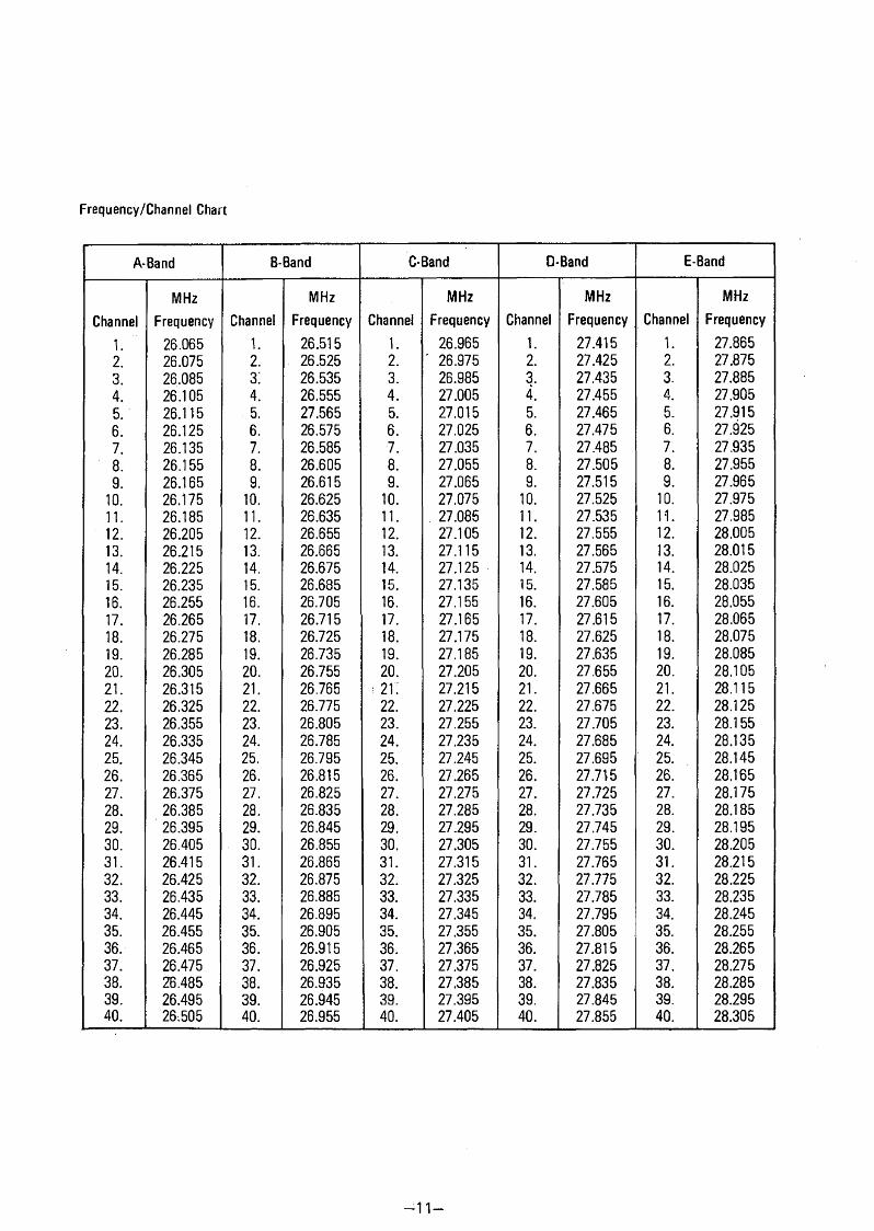
Frequency/Channel Chart
A-Band В-Band C-Band D-Band E-Band
ChannelMHz
Frequency ChannelMHz
Frequency ChannelMHz
Frequency ChannelMHz
Frequency ChannelMHz
Frequency1. ' 26.065 1. 26.515 1. 26.965 1. 27.415 1. 27.8652. 26.075 2. 26.525 2. ' 26.975 2. 27.425 2. 27.8753. 26.085 з; 26.535 3. 26.985 3. 27.435 3. 27.8854. 26.105 4. 26.555 4. 27.005 4. 27.455 4. 27.9055. 26.115 5. 27.565 5. 27.015 5. 27.465 5. 27.9156. 26.125 6. 26.575 6. 27.025 6. 27.475 6. 27.9257. 26.135 7. 26.585 7. 27.035 7. 27.485 7. 27.9358. 26.155 8. 26.605 8. 27.055 8. 27.505 8. 27.9559. 26.165 9. 26.615 9. 27.065 9. 27.515 9. 27.965
10. 26.175 10. 26.625 10. 27.075 10. 27.525 10. 27.97511. 26.185 11. 26.635 11. . 27.085 11. 27.535 11. 27.98512. 26.205 12. 26.655 12. 27.105 12. 27.555 12. 28.00513. 26.215 13. 26.665 13. 27.115 13. 27.565 13. 28.01514. 26.225 14. 26.675 14. 27.125 14. 27.575 14. 28.02515. 26.235 15. 26.685 15. 27.135 15. 27.585 15. 28.03516. 26.255 16. 26.705 16. 27.155 16. 27.605 16. 28.05517. 26.265 17. 26.715 17. 27.165 17. 27.615 17. 28.06518. 26.275 18. 26.725 18. 27.175 18. 27.625 18. 28.07519. 26.285 19. 26.735 19. 27.185 19. 27.635 19. 28.08520. 26.305 20. 26.755 20. 27.205 20. 27.655 20. 28.10521. 26.315 21. 26.765 ; 21. 27.215 21. 27.665 21. 28.11522. 26.325 22. 26.775 22. 27.225 22. 27.675 22. 28.12523. 26.355 23. 26.805 23. 27.255 23. 27.705 23. 28.15524. 26.335 24. 26.785 24. 27.235 24. 27.685 24. 28.13525. 26.345 25. 26.795 25. 27.245 25. 27.695 25. 28.14526. 26.365 26. 26.815 26. 27.265 26. 27.715 26. 28.16527. 26.375 27. 26.825 27. 27.275 27. 27.725 27. 28.17528. 26.385 28. 26.835 28. 27.285 28. 27.735 28. 28.18529. 26.395 29. 26.845 29. 27.295 29. 27.745 29. 28.19530. 26.405 30. 26.855 30. 27.305 30. 27.755 30. 28.20531. 26.415 31. 26.865 31. 27.315 31. 27.765 31. 28.21532. 26.425 32. 26.875 32. 27.325 32. 27.775 32. 28.22533. 26.435 33. 26.885 33. 27.335 33. 27.785 33. 28.23534. 26.445 34. 26.895 34. 27.345 34. 27.795 34. 28.24535. 26.455 35. 26.905 35. 27.355 35. 27.805 35. 28.25536. 26.465 36. 26.915 36. 27.365 36. 27.815 36. 28.26537. 26.475 37. 26.925 37. 27.375 37. 27.825 37. 28.27538. 26.485 38. 26.935 38. 27.385 38. 27.835 38. 28.28539. 26.495 39. 26.945 39. 27.395 39. 27.845 39. 28.29540. 26:505 40. 26.955 40. 27.405 40. 27.855 40. 28.305
- 1 1 -
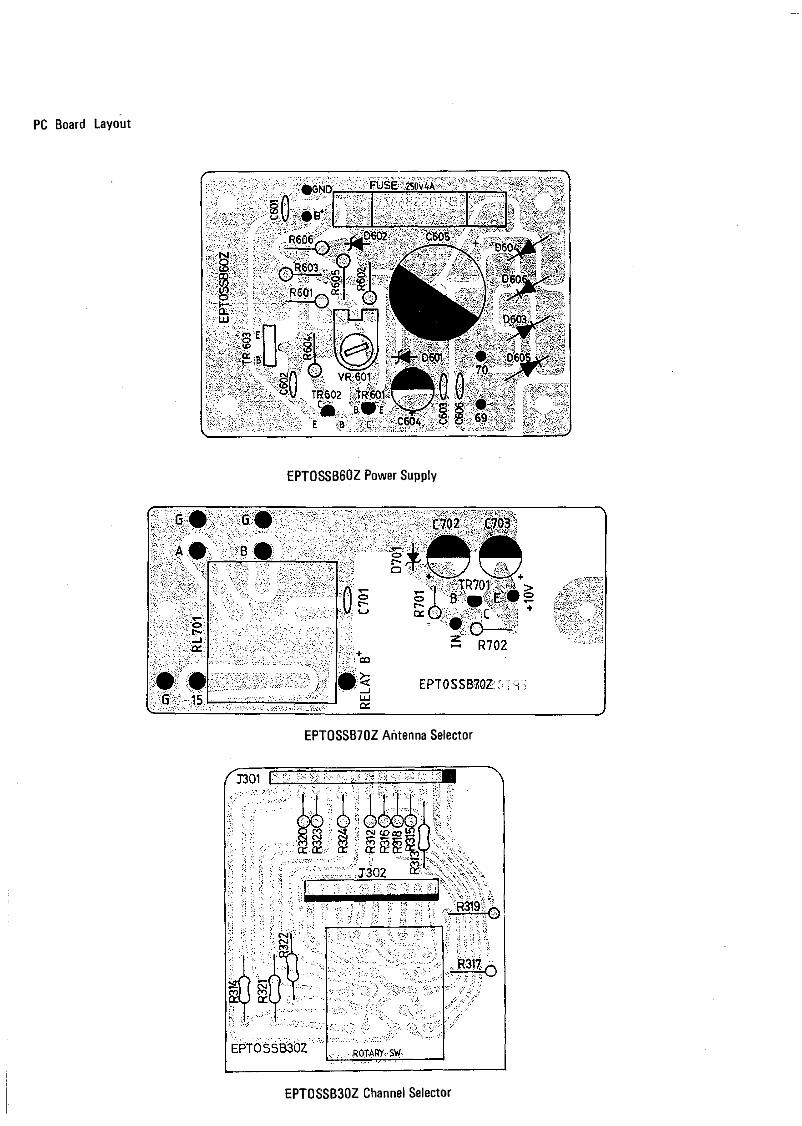
PC Board Layout
EPTOSSB60Z Power Supply
EPTOSSB70Z Aritenna Selector
EPTOSSB30Z Channel Selector
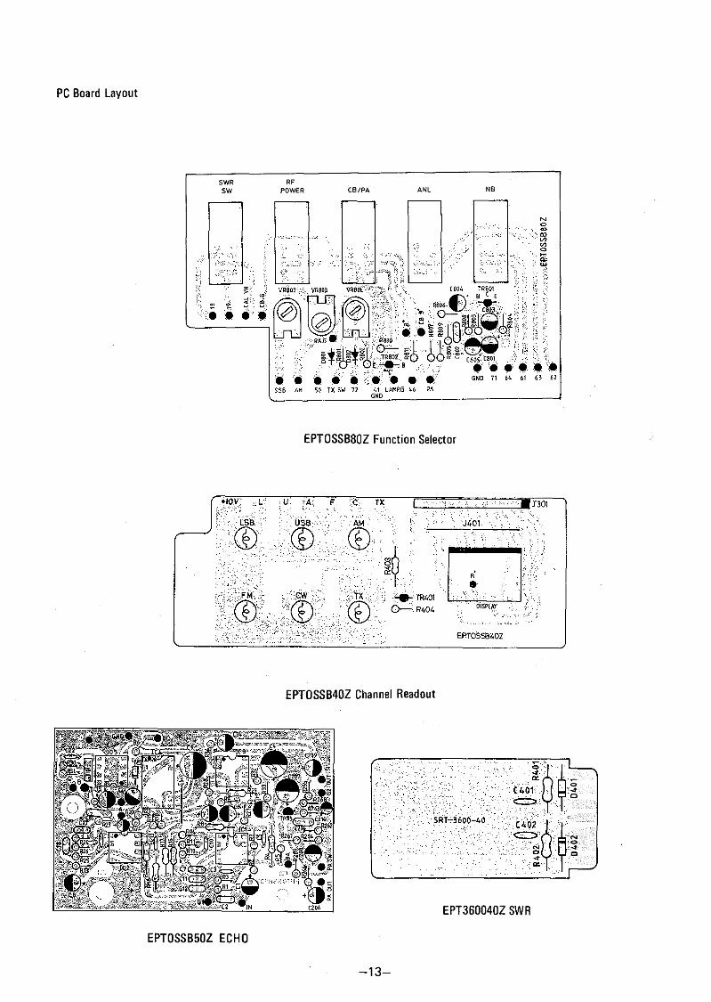
PC Board Layout
SWR RFSW POWER С В /Р Д ANL NB
EPTOSSB80Z Function Selector
EPÏ0SSB4ÛZ Channel Readout
EPT0SSB50Z ECHO
EPT360040Z SWR
13
0402
04
01
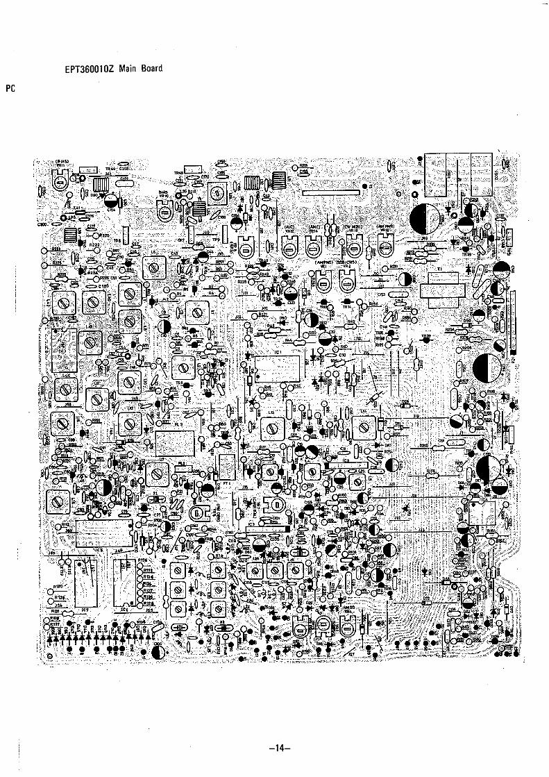
EPT360010Z Main Board
PC
■14-
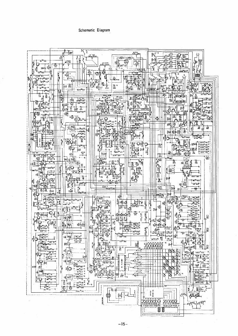
Schematic Diagram
- 1 5 -
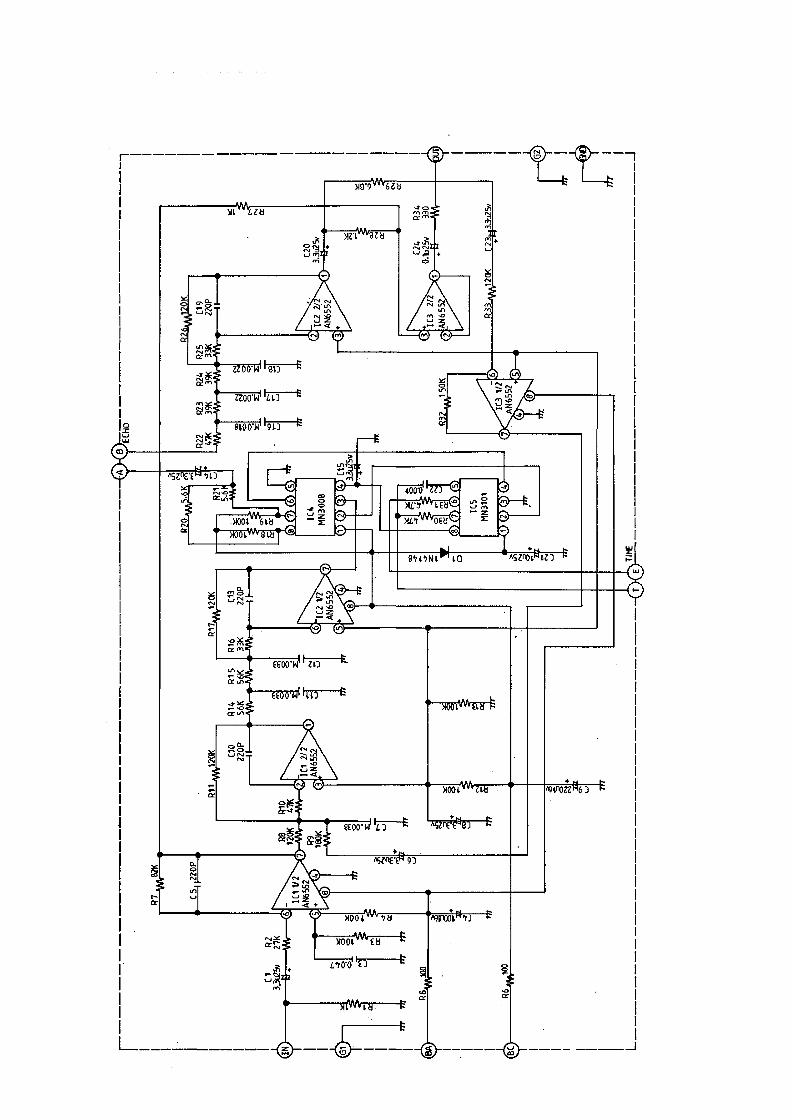
TIME

Replacement Part List
Circuit Symbol Description Part NO. Circuit Symbol Description Part NO.R216 Resistor Carbon RCP 141094Z R3, 86. Resistor Carbon RCU 146814Z
1 ohm MW 680 ohm MWR218 Resistor Carbon RCP 142294Z R 67 Resistor Carbon RCU 148214Z
2.2 ohm MW 820 ohm MWR410 Resistor Carbon RCP 141014Z R 33, 53, 59, 65, Resistor Carbon RCU 141024Z
100 ohm MW 91,104,105, T K ohm MWR 402 Resistor Carbon RCP 141514Z 110,112,147,
150 ohm MW 149, 150,151,R196 Resistor Carbon RCP 146814Z 157, 172,209,
680 ohm MW 214, 236, 311,R192 Resistor Carbon RCP141024Z 312,313,315,
1 K ohm MW 316, 317,319,R74 Resistor Car bon RCP 142224Z 320, 323, 324,
2,2Kohm MW 701,804,809,R23 Resistor Carbon RCP142724Z 811.
2.7 K ohm MW R82,177. Resistor Carbon RCU 141224ZR102, 107, 106, Resistor Carbon RCP143324Z 1.2K ohm MW
250. 3.3Kohm MW R18,81,90,190 Resistor Carbon RCU 141524ZR 47 Resistor Carbon RCP 143924Z 193,221,227. 1.5K ohm MW
3.9 K ohm MW R233 Resistor Carbon RCU 141824ZR79 Resistor Carbon RCP 141034Z 1.8K ohm MW
10K ohm MW RI 7,24,64,68, Resistor Carbon RCU 142224ZR195 Resistor Carbon RCP 142234Z 87, 108, 113, 2.2K ohm MW
22K ohm MW 155,180,189,R131 Resistor Carbon RCP 144734Z 191,257,803,
47 K ohm MW 805,807.R 253 Resistor Carbon R CM 143304B R7, 25, Resistor Carbon RCU 142724Z
33 ohm MW 2.7K ohm MWR9, 94. Resistor Carbon RCM 146804B R16, 22,51,52, Resistor Carbon RCU 143324Z
68 ohm MW 58,95,115, • 3.3K ohm MWR30, 161,237. Resistor Carbon RCM 141014B 141,158,202,
100 ohm MW 244,245,259.R154 Resistor Carbon RCM 142214B R50, 124. Resistor Carbon RCU 143924Z
220 ohm MW 3.9 K ohm MWR 44 Resistor Carbon RCM 146814B R77,146,156, Resistor Carbon RCU 144724Z
680 ohm MW 178,182, 183, 4,7 K ohm MWR56, 66, 80, 140 Resistor Carbon RCM 141024B 185,186,207,
200,211,212, 1 K ohm MW 802,808.313,314,321, R78,85, 184, Resistor Carbon RCU 145624Z322, 403. 239,801. 5.6K ohm MW
R48, 226. Resistor Carbon RCM 141524B R12, 31,35,63, Resistor Carbon RCU 146824Z1.5Kohm MW 76,119,148, 6.8 K ohm MW
R 205 Resistor Carbon RCM 141824B 254.1.8Kohm MW R83, 248. Resistor Carbon RCU 148224Z
R251 Resistor Carbon RCM 142224B 8,2K ohm MW2,2Kohm MW R1,11,14,57, Resistor Carbon RCU 141034Z
R163, 238. Resistor Carbon RCM 145624B 61,62,71,114 10K ohm MW5.6Kohm MW 117,123,142,
R49,164, 197, Resistor Carbon RCM 141034B 152,153,160,249. 1oK ohm MW 169, 174,187,
R 229 Resistor Carbon RCM 141834B 194, 206, 134,18K ohm MW 242,258,404,
R 38 Resistor Carbon RCM 143934B 806,810.39K ohm MW R173 Resistor Carbon RCU 141234Z
R 27 Resistor Carbon RCM 1447 34B 12K ohm MW47 IC ohm MW R118,166. Resistor Carbon RCU 141534Z
R 39 Resistor Carbon RCM 142224B 15K ohm MW220Kohm MW R84, 96, 144. Resistor Carbon RCU 142234Z
R 204 Resistor Carbon RCM 144744B 22 K ohm MW470Kohm MW R 235 Resistor Carbon RCU 142734Z
R220 Resistor Carbon RCU 141Q04Z 27 K ohm MW10 ohm MW R2 Resistor Carbon RCU 143334Z
R241 Resistor Carbon RCU 141504Z 33K ohm MW15 ohm MW R6, 54,55,89, Resistor Carbon RCU 144734Z
RI 99,215,224, Resistor Carbon RCU 144704Z 125,126,127, 47 K ohm MW252. 47 ohm MW 128,129,130,
R111, 121,198, Resistor Carbon RCU 145604Z 132,133,134,203. 56 ohm MW 135,136,137,
R26, 32,69,70, Resistor Carbon RCU 141014Z 138,139, 171,73, 88,162, 100 ohm MW 201,263,230, 231. R19,75,99,101. Resistor Carbon RCU 146834Z
R28,93, 219, Resistor Carbon RCU 141514Z 68 K ohm MW223. 150 ohm MW R37, 72. Resistor Carbon RCU 148234Z
R21, 120. Resistor Carbon RCU 141814Z 82 K ohm MW180 ohm MW R10, 36,41,42, Resistor Carbon RCU 141044Z
R4, 256. Resistor Carbon RCU 142214Z 45,46,97,98. 100K ohm MW220 ohm MW 167,170,247.
R29, 92. Resistor Carbon RCU 142714Z R106,122,181, Resistor Carbon RCU 142244Z270 ohm MW 188. 220K ohm MW
R5,8,15,20, Resistor Carbon RCU 143314Z R43, 159,260. Resistor Carbon RCU142744Z222,225. 330 ohm MW 270K ohm MW
R 60, 143, 175, Resistor Carbon RCU 144714Z R103 , Resistor Carbon RCU 143944Z208,228,246, 470 ohm MW 390K ohm MW255, 261,318. R13, 168. Resistor Carbon RCU144744Z
R145, 232, 240. Resistor Carbon RCU 145614Z 470K ohm MW560 ohm MW
1 6 -
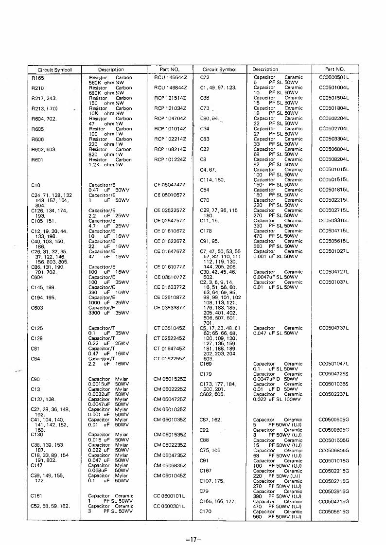
Circuit Symbol Description Part NO. Circuit Symbol Description Part NÖ.R165 Resistor Carbon RCU145644Z C72 Capacitor Ceramic CC0500501L
560K ohm %W 5 PFSL50WVR210 Resistor Carbon RCU 146844Z C1,49,97,123. Capacitor Ceramic CC05Û1004L
680K ohm ’/iW 10 PFSL50WVR217, 243. Resistor Carbon RCP 121514Z C88 Capacitor Ceramic CC0501504L
150 ohm У»W 15 PFSL50WVR213, (-70) Resistor Carbon RCP 121034Z C73 Capacitor Ceramic CC0501804L
10K ohm %W 18 PF SL 50WVR604, 702. Resistor Carbon RCP 104704Z C80.94. Capacitor Ceramic CC0502204L
47 ohm 1W 22 PF SL 50WVR605 Resitor Carbon RCP 101014Z C34 Capacitor Ceramic CC0502704L
100 ohm 1W 27 PF SL 50WVR606 Resistor Carbon RCP 102214Z C83 Capacitor Ceramic CC0503304L
220 ohm 1W 33 PF SL 50WVR602, 603. Resistor Carbon RCP 108214Z C22 Capacitor Ceramic CC0506804L
820 ohm 1W 68 PF SL 50WVR601 Resistor Carbon RCP101224Z : C8 Capacitor Ceramic CC0508204 L
1.2K ohmIW 82 ,PF SL 50WVC4.67. Capacitor Ceramic
100 PFSL50WVCC0501015L
C114,160. Capacitor Ceramic CC0501515LCIO Capacitor/E CE 0504747Z 150- PFSL50WV
0.47 uF 50WV C54 Capacitor Ceramic CC0501815LC24, 71,128,132 Capacitor/E CE 0501057Z 180 PF SL 50WV
143, 157,164, 1 uF 50WV C70 Capacitor Ceramic CC0502215L804. 220 PF SL 50WV
C126, 134, 174, Capacitor/E CE 0252257Z C29, 77,96,115 Capacitor Ceramic CC0502715 L193. 2.2 uF 25WV 180. 270 PF SL 50WV
C105, 151. Capacitor/E CE 0254757Z C11.15. Capacitor Ceramic CC0503315L4.7 ■ uF 25WV 330 PF SL 50WV
C12, 19,20.44, Capacitor/E CE 01610672 C178 Capacitor Ceramic CC0504715L133, 198. 10 uF 16WV 470 PF SL 50WV
C40, 103,150, Capacitor/E CE 0162267Z C91,95, Capacitor Ceramic CC0505615L186. 22 uF 16WV 560 PF SL 50WV
C26, 31,32,35, Capacitor/E CE 0164767Z C7, 47,50, 53, 55 Capacitor Ceramic CC0501027L37, 122,146, 47 uF 16WV 57,82,110,111 0.001 uF SL 50WV156,803,805. 112,119,130,
C86,131,190, Capacitor/E CE 01 61077Z 144, 205,206.701,702. 100 uF 16WV C30, 42,45,46, Capacitor Ceramic CC0504727L
C604 Capacitor/E CE 0351077Z 502. 0.0047uF SL 50WV100 uF 35WV C2, 3, 6,9,14, Capacitor Ceramic CC0501037L
C145,199. Capacitor/E CE 0163377Z 16, 51,56, 60, 0.01 uF SL 50WV330 uF 16WV 63,64,69,85,
C194, 195. Capacitor/E CE 0251087 Z 98,99,101,1021000 uF 25WV 108,113,121,
C603 Capacitor/E CE 0353387Z 176,183,185,3300 uF 35WV 205,401,402,
506,507,601,701,
C125 Capacitor/T CT0351045Z C5,17,23,48,61 Capacitor Ceramic CC0504737L0.1 uF 35WV B2; 65, 66, 68, 0.047 u F SL 50WV
C129 Capacitor/T CT 0252245Z 100,109,120,0.22 uF 25WV 127,135,159,
C81 Capacitor/T CT 01647 45Z 181,188,189,0.47 uF 16WV 202,203, 204,
C84 Capacitor/T CT 0162255Z 603.2.2 uF 16WV C169 Capacitor Ceramic
0.1 uF SL 50WVCC0501047 L
C179 Capacitor Ceramic CC0504726SC90 • Capacitor Myiar CM 0501525Z 0.0047 uFD 50WV
0.0015uF 50WV C173, 177,184, Capacitor Ceramic CC0501036SC13 Capacitor Myiar CM 0502225Z 200,201. 0.01 uF D 50WV
0.0022uF 50WV C602, 606. Capacitor Ceramic CC0502237LC137, 138. Capacitor Myiar CM 0504725Z 0,022 uF SL 100WV
0.0047 uF 50WVC27,28, 36,148, Capacitor Myiar CM 0501025Z
192. 0.001 uF 50WVC41, 104, 140, Capacitor Myiar CM 0501035Z C87, 162. Capacitor Ceramic CC0500505G
141,142, 152, 0.01 uF 50WV 5 PF 50WV (UJ)168. C92 Capacitor Ceramic CC0500805G
Cl 36 Capacitor Myiar CM 0501 535Z 8 PF 50WV (UJ)0.015 uF 50WV C88 Capacitor Ceramic CC0501505G
C38, 139,153, Capacitor Myiar CM 0502235Z 15 PF 50WV (UJ)187. 0.022 uF 50WV C75, 106. Capacitor Ceramic CC0506805G
C18, 33, 89, 154 Capacitor Myiar CM 05047 35Z 68 PF 50WV (UJ)191,802. 0.047 uF 50WV C91 Capacitor Ceramic CC0501015G
C147 Capacitor Myiar CM 0506835Z 100 PF 50WV (UJ)0.Û68uF 50 WV Cl 67 Capacitor Ceramic CC05Q2215G
C39, 149,155, Capacitor Myiar CM 0501045Z 220 PF 50Wv (UJ)172. 0.1 uF 50WV C107,175. Capacitor Ceramic
270 PF 50WV (UJ)CC0502715G
C79 Capacitor Ceramic CC0503915GC161 Capacitor Ceramic CC 0500101 L 390 PF 50WV (UJ)
1 PF SL 50WV C165,166,177. Capacitor Ceramic CC0504715GC52, 58,59, 182. Capacitor Ceramic CC 0500301 L 470 PF 50WV (UJ)
3 PF SL 50WV C170 Capacitor Ceramic CC0505615G560 PF 50WV (UJ)
- 1 7 -

Circuit Symbol Description Part NO. Circuit Symbol Description Part NO.C25,76. Capacitor Ceramic CC0501505A TR3, 4, 5,7, 12, Transistor T2SC00945Q
1 5 PF 50WV (CH) 13,14,15.16 2SC945AQ/2SC1815 YСЭЗ Capacitor Ceramic CC0503305A 23, 31,32, 35
3 3 PF 50WV (CH) 37,39,40,48 'C501,502. Capacitor Ceramic CC0503904A 49, 52, 53, 54
3 9 PF50WV (CH) 401,602,801C158 Capacitor Ceramic CC0508205A TR22.46. Transistor T2SC01730 L
8 2 PF50WV (CH) 2SC1730LC124, 163. Capacitor Ceramic CC0501015A TR36, 38,50. Transistor T2SB00525C
100 PF50WV (CH)TR6, 34.
2SB525CTransistor2SA733P
T2SA00733P
C43 Capacitor Ceramic CC0501805D TR33, 42. Transistor T2SC01815R1 8 PF50WV (RH) 2SC1815GR
C78' Capacitor Ceramic CC0503305D TR45 Transistor T2SC02086Z3 3 PF50WV (RH) 2SC2086
C116, 118. Capacitor Ceramic CC0503905D TR701,802. Transistor T2SC01318S3 9 PF 59WV (RH) 2SC1318S
C78,117. Capacitor Ceramic CC0505605D TR603 Transistor T2SD00613D5 6 PF 50WV (RH)
TR6012SD613D Transistor 2SC1571G
T2SC01571G
LI I.F.T. ECIFT12000 TR18 FET EZZJ00310ZYTKAC-24073F J310
L2, 13. I.F.T. ECIFT12001YTKAC-25365NI.F.T. ECIFT12002 D93 Diode EDI N04003ZL3,4.7MC-7172ABW 1 N4003
L5 I.F.T. ECIFT12003 D29 Diode ED1 N0400727MC-7174Y 1 N4007
L6 I.F.T. ECIFT12004 D15.16. Diode EDMC00301ZYKXNF-25439N MC301I.F.T. ECI FT12005 01,2,10,11,23 Diode DE1 N00060ZYTKXC-25114N 24,83,401, 1 N60
L10, 11,44. I.F.T. ECIFT12007 402.YTKAC-27242A D65, 79. Diode EDK800262Z
L12_ I.F.T. ECI FT12008 KB262 OrangeYTKAC-27869N D77 Otode EDK800362Z
L14 I.F.T. ECI FT12009 К В362 WhiteYTKAC-27241A D88, 89. Diode EDMV00001Y
L16, 18.43. I.F.T. ECIFT12010 MV1YYTKXC-18501N D37 Diode EDMV00201Z
L19,20,21. I.F.T. ECIFT12012 MV201113CN-6514X D30 Diode EDSV00251Z
L28 I.F.T. ECIFT12Q13 SVC251113CN06485Z D3, 4, 5, 6, 7, 8, Diode ED1N04148Z
L40 I.F.T. ECIFT12014 9,12,13,14, 1N4148YTKXC-27205BZD 17,18,19,20,
L42 I.F.T. ECIFT12015 21,22,25,26,YTKXC-24279UH 27,28,31,32,
L26,27. I.F.T. ECIFT12016 33,34,35,36,11CN-6344Z 38,39,40,49,
L17 I.F.T. ECIFT12017 57,58,59,60,YVTKXNA-XP1376Y 61,62,63,64,
L18 I.F.T. ECIFT12022 66, 67,68,69,TKXB-286Q9AN 70,71,72,73,
80,81,82,84,85,86,87,90,
L39 Spring Coil ECSPG18000 91,92,94,95,0.8cx4.2cx6.5T 96,97,98,99,
L37 Spring Coil ECSPG18001 100, 101,102,Q.8cx3.5cx7T 103,104,105,
L34 Spring Coil ECSPG18002 106, 107,108,0.8cx4.5cx7T 109,110,111,
L31,32. Spring Coil ECSPG18003 501,801,802,0.8cx6.5cx7.5T D78 Diode Zener
7.5V 500MW XE-072EDZD05739Z
D76 Zener Diode* 5.1V EDZD05519ZTR41 Transistor T2SA004730 500MW UZ-5.1B
2SA473(0) With D701 Zener Diode EDZD05110ZMica, Teflon 11VWasher 0602- Zener Diode EDZD10160Z
TR51 Transistor T2SA010120 16.2V 1W2SA1012(0) With D601 Zener Diode EDZD10569ZMica, Teflon Washer 5.6V IW
TR44 Transistor T2SC02166C D803, 804, 805 Diode EDI N05404Z2SC2166C With Mica Teflon Washer
806. 1 N5404
TR43 Transistor2SC1969C/2SC2312C
T2SC01969CX2 Crystal EC Y1446002
Teflon Washer 14.460MHz + -20PPMTR8, 17, 19,29. Transistor T2SC01674L X1 Crystal ECY1024002
2SC1674L 1Q.240MHZ + —20PPMTR1,2, 9, 10, 1 f Transistor T2SC01675L X4 Crystal ECY1069752
20,21,24,25 2SC1675L 10.6975M H z + - 2 026,27,30,47 PPM -,

Circuit Symbol Description Part NO. Circuit Symbol Description Part NO.
FL3 Crystal. 10.695MHz 8 Pole
EFX8106952
FL2 Ceramic Filter SFE10.7MX
EFCFE107MX
FL1 Ceramic Filter CFW455HT
EFCFW455HT
ICI !C LA6324/LM324 ENSA06324ZIC3 IC AN612 ENMI00612ZIC5 ICMC145106 ENMC45106ZIC9 IC S042P EN8M00042PIC6, 7. ICMC14008B ENMC14008BIC2 IC UPC1028H ENNE01028HIC8 IC TA7222AP With
MicaENTA07222P
IC4 IC JRC4558D ENJR04558D
L33 RF Coil 0.23 UH SU-028C
ECR FZ 10001
L503,504. Choke Coil 0.47 UH
ECCHK16000
L501 Choke Coil 5.6 UH
ECCHK16001
L46 Choke Coil 100 UH
ECCHK16002 ■
L22,23,24,25, Choke Coil ECCHK1600329,30,45. 470 UH
T1 Choke Coil EI-19 TF-083
ECCHK16Û04
L9,35,47,502. Bead Core D 3.5 x 6 x 1.2 SU-B-172D
ECBAD18504
L41 Bead Coil E ' 3.5 x 6 x 1.2 SU-8-172E
ECBAD18505
L15.36, 38. Bead Coil F 3.5 « 6 x 1.2 SU-B-172F
ECBAD18506
(-60) P.C.B. Fuse 4A 250V 6.5c x 30 W/Copper Wire
EX02N40208
{—7Q) P.C.B. Relay 12V ’ EX05N40805
VR10 Semi-Fixed Resistor 80 Lay 100 ohm
RE10100018
VR601 Semi-Fixed Resistor 80 Lay 500 ohm
RE50100001
VR14, 803. Semi-Fixed Resistor ' 80 Lay 1 К
RE10200003
VR11, 16,801, Semi-Fixed Resistor RE30200019802. 80 Lay 3 К
VR13 . Semi-Fixed Resistor 80 Lay 5 К
RE5020Û006
VR1,2, 5,7,12. Semi-Fixed Resistor 80 Lay 10 К
RE10300009
VR8 Semi-Fixed Resistor 80 Lay 100 К
RE10400020
VR3, 4. Semi-Fixed Resistor 80 Lay 500 К
RE50400021
19