Embed Size (px)
Citation preview

ALTERNATOR PROTECTION DEMO PANEL USING DIFFERENTIAL PROTECTION SCHEME
Abhishek Gupta1, Akash Anand2, Amar Kumar Mani3, Ankit Kumar4,D.S. Bankar 5
1 Student, Electrical Department, Bharati Vidyapeeth Deemed University, Pune, India2 Student, Electrical Department, Bharati Vidyapeeth Deemed University, Pune, India3 Student, Electrical Department, Bharati Vidyapeeth Deemed University, Pune, India4 Student, Electrical Department, Bharati Vidyapeeth Deemed University, Pune, India5 H.O.D., Electrical Department, Bharati Vidyapeeth Deemed University, Pune, India
ABSTRACT
The various faults on an alternator may leads to discontinuity in power supply, sudden voltage drop, burning of windings of alternator, economical loss etc.The differential protection scheme is demonstrated by alternator protection panel. It is having protection scheme for Line to line fault, Earth fault and Interturn fault.By using this protection panel, we will be able to perform various experiments related to an alternator fault protection and correspondingly their characteristics can be plotted.
Key Words: Alternator, Circuit breaker, Differential relay, Load, Rheostat--------------------------------------------------------------------***----------------------------------------------------------------------1. INTRODUCTIONAn alternator is very important and costly equipment in power system. It should not be disconnected as far as possible because that would result in power shortage. While selecting the protective scheme, the protection of complete unit and stability of system due to disturbance in alternator should also be considered.The main disturbance creating fault on an alternator are insulation failure, mechanical stress imposed and temperature rise. The devices used in generator protection, ensure the fault, made dead as quickly as possible.The differential protection scheme is demonstrated by alternator protection demo panel. To protect 3 phase alternator we are using AC current relay. It is easy to operate and simple in design. The current transformer senses the incoming and outgoing current from stator windings of 3 phase star connected alternator & it is fed to AC circulating current relay. When the fault occurs, the difference between the magnitude and phase angle of current of both the CTs will change. The fault impedance affects the change in current. The change in differential current will actuate the differential relay & it will operate within specific time duration as per the time settings of the differential relay.
Different fault condition can be created by using the switches which simulate the fault. In this panel the line to line fault, earthfault and interturn fault can be created and demonstration can be done. The demo panel also comprises fault annunciation and system, digital indicating meters for frequency line voltage and line current. The circuit breaker on output side of alternator is used to open the machine from load under fault condition. The phase indicating lamps, fault indication, time and field control autotransformer are also used incorporated in the protection demo panel.
2. CLASSIFICATION OF FAULTThe stator faults are as follows-
Line to Line Fault:Line to line fault generally occurs when any 2 phases comes in contact with each other for ex- R-Y, Y-B, B-R. This generally happens due to insulation failure of the windings.
Line to line fault can be created by using fault simulating switch which is placed on front side of the panel. Any of the 3 fault which are stated above can be created using the switch
_______________________________________________________________________________________ 1

Line to Ground Fault:
In this type of fault any of the 3 phases comes in contact with earth and hence fault occurs. This fault can be created in the panel with the help of fault simulating switch(L-G switch) on the front side of the panel.
Interturn Fault:In this fault any one of the winding becomes short circuited within itself i.e the 2 turns comes in contact with each other. This
fault can be created on the alternator by using th fault simulating switch on the panel which is connected across the winding through a variable resistance.To clear such kind of faults in least possible time for minimizing the damage to the machine the automatic protection is very necessary.
3. PROTECTION SCHEME USED Differential Protection Scheme
The figure shows the CTs arrangement of star connected alternator. Current in pilot wires fed through CT connections are equal in case of normal operating conditions and after fault clearance. The operating coil of the relay has net zero differential current. Now when the fault is created the balance gets disturbed. The difference of current through both the CTs flows through the operating coil of the relay which cause relay to operate. Now the relay operates the circuit breaker which results in tripping of alternator.
4. COMPONENTS AND ITS SPECIFICATIONS
Sr. No. DESCRIPTION SPECIFICATION
1 Alternator 5 KVA, 3 Phase, 415V, 1500 rpm, Star connected
2 DC Shunt Motor 7.5HP, 220V, 4.7A
3 Main Switch 16A
4 Fault Switches 32A, 2 pole, Rotary switch
5 Digital Voltmeter 0-500V AC
6 Digital Ammeter 0-10A AC
7 Frequency Meter 0-50 Hz
8 % Differential 1A, CT, 20-30-40-50%
_______________________________________________________________________________________ 2
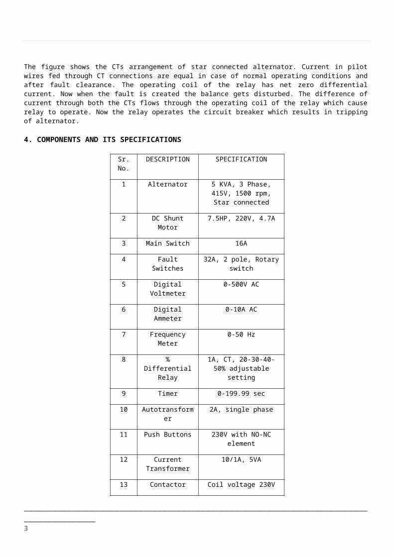
Relay adjustable setting
9 Timer 0-199.99 sec
10 Autotransformer 2A, single phase
11 Push Buttons 230V with NO-NC element
12 Current Transformer
10/1A, 5VA
13 Contactor Coil voltage 230V AC
14 Connecting Wires 1.5ft long (red & black)
15 Hooter 230V Electronic
16 Indicating lamps 230V AC (series register)
17 Resistors 10ohm, 300W
(FRONT PANEL VIEW)
5. INVERSE TIME RELAYAn inverse time relay is one in which the operating time approximately inversely proportional to the magnitude of the actuating quantity. The time of operation of the relay decreases steadily with the increase of current.
There is provision of four level current setting which is 20%, 30%, 40% & 50% through which we can adjust the pickup current to any required value. It is achieved by the use of tapping on the relay operating coil & are brought out to a plug reach.
The four level plug which we are using on the panel permits to alter the number of turns on the relay coil which results in change of torque on the disc of relay & hence time of operation. Pickup current is given as :
Pickup current= Rated secondary current of CT*Current setting.
We are also providing a time relay plug setting on the panel which will allow us to adjust the time of operation of relay.
_______________________________________________________________________________________ 3

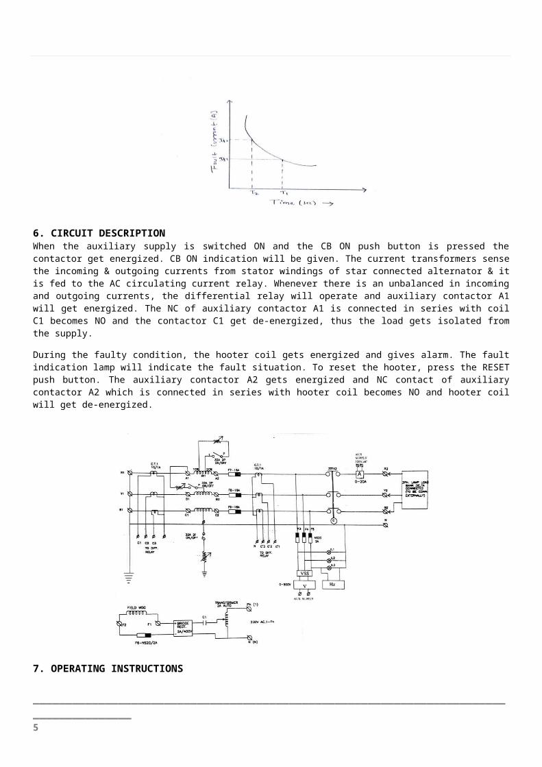
6. CIRCUIT DESCRIPTIONWhen the auxiliary supply is switched ON and the CB ON push button is pressed the contactor get energized. CB ON indication will be given. The current transformers sense the incoming & outgoing currents from stator windings of star connected alternator & it is fed to the AC circulating current relay. Whenever there is an unbalanced in incoming and outgoing currents, the differential relay will operate and auxiliary contactor A1 will get energized. The NC of auxiliary contactor A1 is connected in series with coil C1 becomes NO and the contactor C1 get de-energized, thus the load gets isolated from the supply.
During the faulty condition, the hooter coil gets energized and gives alarm. The fault indication lamp will indicate the fault situation. To reset the hooter, press the RESET push button. The auxiliary contactor A2 gets energized and NC contact of auxiliary contactor A2 which is connected in series with hooter coil becomes NO and hooter coil will get de-energized.
7. OPERATING INSTRUCTIONS
1. Connect alternator machine to terminal board with proper terminal sequence. Connect auxiliary supply cable with correct polarity and ensure earth wire is properly connected to demo panel.2. Make the motor side connection through DC motor starter and speed control rheostat3. Keep earth fault, interturn fault and L-L fault switch, main switch in off position4. Keep field control autotransformer to minimum positionSwitch on the auxiliary supply through main switch. Kit on indication will be ON.5. Start the DC motor with the help of starter and adjust the speed of machine which gives 50 hz frequency on display.6. Increase the field excitation voltage in such a way the alternator line voltage will be equal to 415 volts. Check all three line voltage and observed indicating lamps.
_______________________________________________________________________________________ 4
7. Connect the external load to alternator through switching on the circuit breaker with the help of push buttons. Observe the circuit breakers on indication.8. Take the voltmeter, ammeter and frequency meter reading for different load conditions.
9. With some specific load, create the fault with the fault simulating switches one by one and observe the tripping of differential relay. The time delay between the instant at which fault is created and the AC circulating relay operates is measured with the help of digital meter.
10. When protective relay operates the annunciation system will give indication and audio alarm
11. Repeat the above procedure for the different values of resistances connected in series with the fault simulating switches.
12. From the reading taken plot the inverse time characteristics for different faults.
8. RESULT TABLE
CONDITION SETTING TIME
L-L Fault 50% 2.372
40% 1.432
L-G Fault 40% 36.53
30% 20.76
Interturn Fault
40% 2.082
30% 1.140
9. CONCLUSIONAn alternator is very important and costly equipment in power system. It should not be disconnected as far as possible because that would result in power shortage. While selecting the protective scheme, the protection of complete unit and stability of system due to disturbance in alternator should also be considered.
The protection scheme used in our panel is the differential protection in which the difference in the incoming and outgoing current from the terminals of the current transformer energizes the relay coil which further trips the circuit breaker. There is difference in incoming and outgoing current due to fault.
The panel is having the protection scheme against interturn fault, L-L fault and earth fault
Now as per our objectives the panel will be able to plot inverse time characteristics of the fault in an alternator.
The panel will have minimum external connections which will ease the experimental purposes.
Thus the Alternator protection panel will be beneficial for conducting the experiments for the bachelor and masters courses in our department’s laboratory.
ACKNOWLEDGEMENTWe put our best efforts in this project. Through our entire project we have been continuously supported and guided by several individuals. We are highly obliged to all of them for their continuous help.
We owe great debt to Prof. DS BANKAR for his guidance and regular supervision as well for providing vital information regarding the project titled “ALTERNATOR PROTECTION DEMO PANEL” and also his kind support in completing the project.
_______________________________________________________________________________________ 5

It would not have been possible without the encouragement and continuous motivation by our parents and friends regarding the completion of the project.
We would like to express our special gratitude and thanks to industry personnel for giving us such information on internet.
In the end we also appreciate and thankful to our college in developing the project & people who helped us willingly with their abilities to achieve desired objective.
REFERENCES
[1]. J.B. Gupta, “A Course In Power System”, Katson Publication
[2]. D.S. Bankar, “Switchgear & Protection”, Techmax Publication
[3]. www.mdelectricals.com
[4].www.electrical4u.com/alternator-or-synchronous-generator/
[5]. www.slideshare.net
[6] www.ijictrd.net
[7]. www.atmel.com
[8]. S.S. RAO,” Switch Gear And Protection”, Khanna Publication
[9]. M. L. SONI, P.V. GUPTA, U.S. BHATNAGAR, “A Course In Electrical Power”, Dhanpat Rai & Sons
[10]. B. RAM, “Power System Protection”
[11]. S. P. PATRA, S. K. BASU, S. CHOWDHRY, “Power System Protection”, Oxford & IBH Publisher
BIOGRAPHIES
Abhishek Gupta, B.Tech., Final year student from Electrical Engineering Dept., Bharati Vidyapeeth Deemed University, College of Engineering, [email protected]
Akash Anand, B.Tech., Final year student from Electrical Engineering Dept., Bharati Vidyapeeth Deemed University, College of Engineering, Pune. [email protected]
_______________________________________________________________________________________ 6

Amar Kumar Mani, B.Tech., Final year student from Electrical Engineering Dept.Bharati Vidyapeeth Deemed University, College of Engineering, Pune. [email protected]
Ankit kumar, B.Tech., Final year student from Electrical Engineering Dept., Bharati Vidyapeeth Deemed University, College of Engineering, Pune. [email protected]
Dr. Prof. D. S .Bankar, Head Of Department, Electrical Engineering Department of Bharati Vidyapeeth Deemed University College of Engineering Pune, India.
_______________________________________________________________________________________ 7