Embed Size (px)
Citation preview
Network Infrastructures A.A. 2009-2010
Long Term Evolution (LTE):
from an architectural point of view
Name of authors: Michele Fiocca, Francesco Salvatore
2
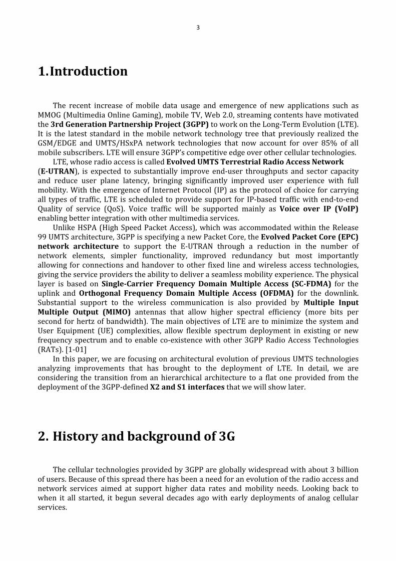
I. Contents
1. Introduction ...................................................................................................................................... 3
2. History and background of 3G ............................................................................................................ 3
2.1. Before 3G ................................................................................................................................... 4
2.2. 3GPP advent ............................................................................................................................... 5
2.3. 3G Evolution ............................................................................................................................... 5
3. Requirements of LTE .......................................................................................................................... 6
3.1. Capabilities ................................................................................................................................. 6
3.2. System performance ................................................................................................................... 6
3.3. Spectrum Flexibility..................................................................................................................... 7
4. System architecture evolution ........................................................................................................... 7
4.1. UMTS radio access network ......................................................................................................... 8
4.1.1. Serving and drift RNC ....................................................................................................................... 10
4.2. LTE radio access network ........................................................................................................... 11
4.2.1 eNodeB roles and functionality ......................................................................................................... 12
4.3. SAE Architecture Baseline ......................................................................................................... 13
5. Interfaces ........................................................................................................................................ 15
5.1. S1 interface user plane .............................................................................................................. 15
5.2. S1 interface control plane.......................................................................................................... 16
5.3. X2 interface user plane .............................................................................................................. 17
5.4. X2 interface control plane ......................................................................................................... 17
6. LTE Handovers ................................................................................................................................. 18
6.1. X2 Based handover ................................................................................................................... 18
6.2. S1 Based Handover ................................................................................................................... 20
7. Conclusions ..................................................................................................................................... 22
II. References ...................................................................................................................................... 22
3
1. Introduction
The recent increase of mobile data usage and emergence of new applications such as
MMOG (Multimedia Online Gaming), mobile TV, Web 2.0, streaming contents have motivated
the 3rd Generation Partnership Project (3GPP) to work on the Long-Term Evolution (LTE).
It is the latest standard in the mobile network technology tree that previously realized the
GSM/EDGE and UMTS/HSxPA network technologies that now account for over 85% of all
mobile subscribers. LTE will ensure 3GPP’s competitive edge over other cellular technologies.
LTE, whose radio access is called Evolved UMTS Terrestrial Radio Access Network
(E-UTRAN), is expected to substantially improve end-user throughputs and sector capacity
and reduce user plane latency, bringing significantly improved user experience with full
mobility. With the emergence of Internet Protocol (IP) as the protocol of choice for carrying
all types of traffic, LTE is scheduled to provide support for IP-based traffic with end-to-end
Quality of service (QoS). Voice traffic will be supported mainly as Voice over IP (VoIP)
enabling better integration with other multimedia services.
Unlike HSPA (High Speed Packet Access), which was accommodated within the Release
99 UMTS architecture, 3GPP is specifying a new Packet Core, the Evolved Packet Core (EPC)
network architecture to support the E-UTRAN through a reduction in the number of
network elements, simpler functionality, improved redundancy but most importantly
allowing for connections and handover to other fixed line and wireless access technologies,
giving the service providers the ability to deliver a seamless mobility experience. The physical
layer is based on Single-Carrier Frequency Domain Multiple Access (SC-FDMA) for the
uplink and Orthogonal Frequency Domain Multiple Access (OFDMA) for the downlink.
Substantial support to the wireless communication is also provided by Multiple Input
Multiple Output (MIMO) antennas that allow higher spectral efficiency (more bits per
second for hertz of bandwidth). The main objectives of LTE are to minimize the system and
User Equipment (UE) complexities, allow flexible spectrum deployment in existing or new
frequency spectrum and to enable co-existence with other 3GPP Radio Access Technologies
(RATs). [1-01]
In this paper, we are focusing on architectural evolution of previous UMTS technologies
analyzing improvements that has brought to the deployment of LTE. In detail, we are
considering the transition from an hierarchical architecture to a flat one provided from the
deployment of the 3GPP-defined X2 and S1 interfaces that we will show later.
2. History and background of 3G
The cellular technologies provided by 3GPP are globally widespread with about 3 billion
of users. Because of this spread there has been a need for an evolution of the radio access and
network services aimed at support higher data rates and mobility needs. Looking back to
when it all started, it begun several decades ago with early deployments of analog cellular
services.
4
2.1. Before 3G
The US Federal Communications Commission (FCC) approved the first commercial car-
borne telephony service in 1946, operated by AT & T. In 1947 AT & T also introduced the
cellular concept of reusing radio frequencies, which became fundamental to all subsequent
mobile-communication systems. Commercial mobile telephony continued to be car-borne for
many years because of bulky and power-hungry equipment. In spite of the limitations of the
service, there were systems deployed in many countries during the 1950s and 1960s, but the
users counted only in thousands at the most. The big uptake of subscribers and usage came
when mobile communication became an International concern and the industry was invited
into the process. The first International mobile communication system was the analog NMT
system (Nordic Mobile Telephony) which was introduced in the Nordic countries in 1981, at
the same time as analog AMPS (Advanced Mobile Phone Service) was introduced in North
America. Other analog cellular technologies deployed worldwide were TACS and J-TACS.
They all had in common that equipment was still bulky, mainly car-borne, and voice quality
was often inconsistent, with ‘cross-talk’ between users being a common problem.
The analog cellular systems supported ‘plain old telephony services’ that is voice with
some related supplementary services. With the advent of digital communication during the
1980s, the opportunity to develop a second generation of mobile-communication standards
and systems, based on digital technology, surfaced. With digital technology came an
opportunity to increase the capacity of the systems, to give a more consistent quality of the
service, and to develop much more attractive truly mobile devices.
In Europe, the telecommunication administrations in CEPT (European Conference of
Postal and Telecommunications Administrations) initiated the GSM project to develop a
pan-European mobile-telephone system. The GSM activities were in 1989 continued within
the newly formed European Telecommunication Standards Institute (ETSI). After evaluations
of TDMA, CDMA, and FDMA based proposals in the mid-1980s, the final GSM standard was
built on TDMA. Development of a digital cellular standard was simultaneously done by TIA in
the USA resulting in the TDMA-based IS-54 standard, later simply referred to as US-TDMA. A
somewhat later development of a CDMA standard called IS-95 was completed by TIA in 1993.
In Japan, a second-generation TDMA standard was also developed, usually referred to as PDC.
All these standards were ‘narrowband’ in the sense that they targeted ‘low bandwidth’
services such as voice. With the second-generation digital mobile communications came also
the opportunity to provide data services over the mobile-communication networks. The
primary data services introduced in 2G were text messaging (SMS) and circuit-switched data
services enabling e-mail and other data applications. The peak data rates in 2G were initially
9.6 kbps. Higher data rates were introduced later in evolved 2G systems by assigning multiple
time slots to a user and by modifying coding schemes. [1-02]
Packet data over cellular systems became a reality during the second half of the 1990s,
with General Packet Radio Services (GPRS) introduced in GSM and packet data also added to
other cellular technologies such as the Japanese PDC standard. These technologies are often
referred to as 2.5G. The success of the wireless data service iMode in Japan gave a very clear
indication of the potential for applications over packet data in mobile systems, in spite of the
fairly low data rates supported at the time.
With the advent of 3G and the higher-bandwidth radio interface of UTRA (Universal
Terrestrial Radio Access) came possibilities for a range of new services that were only hinted
at with 2G and 2.5G. The 3G radio access development is today handled in 3GPP. However, the
initial steps for 3G were taken in the early 1990s, long before 3GPP was formed.
5
What also set the stage for 3G was the internationalization of cellular standardization.
GSM was a pan-European project, but quickly attracted worldwide interest when the GSM
standard was deployed in a number of countries outside Europe. There are today only three
countries worldwide where GSM is not deployed. A global standard gains in economy of scale,
since the market for products becomes larger. This has driven a much tighter international
cooperation around 3G cellular technologies than for the earlier generations. [1-02]
2.2. 3GPP advent
The outcome of the ETSI (European Telecommunications Standards Institute) process in
early 1998 was the selection of Wideband CDMA (WCDMA) as the technology for UMTS in the paired spectrum (FDD) and TD-CDMA (Time Division CDMA) for the unpaired spectrum
(TDD). There was also a decision to harmonize the parameters between the FDD and the TDD
components. The 3d-Generation Partnership Project (3GPP) is the standards-developing body that specifies
the 3G UTRA and GSM systems. 3GPP consists of several Technical Specifications Groups (TSGs). One of these groups, 3GPP TSG RAN is the technical specification group that has developed WCDMA, its evolution HSPA, as well as LTE, and is in the forefront of the technology.
The aim of 3GPP when it was formed in 1998 was to produce global specifications for a 3G mobile system based on an evolved GSM core network, including the WCDMA-based radio access of the UTRA FDD and the TD-CDMA-based radio access of the UTRA TDD mode. The task to maintain and develop the GSM/EDGE specifications was added to 3GPP at a later stage. The UTRA (and GSM/EDGE) specifications are developed, maintained and approved in 3GPP. After approval, the organizational partners transpose them into appropriate deliverables as standards in each region.
With the inclusion of an Evolved UTRAN (LTE) and the related System Architecture Evolution (SAE) in Release 8, further steps are taken in terms of broadband capabilities.
2.3. 3G Evolution
TSG RAN organized a workshop on 3GPP long-term evolution in the fall of 2004. The
workshop was the starting point of the development of the Long-Term Evolution (LTE) radio
interface. After the initial requirement phase in the spring of 2005, where the targets and
objectives of LTE were settled, the technical specification group TSG SA launched a
corresponding work on the System Architecture Evolution, since it was felt that the LTE radio
interface needed a suitable evolved system architecture. The result of the LTE workshop was
that a study item in 3GPP TSG RAN was created in December 2004. The first six months were
spent on defining the requirements, or design targets, for LTE. These were documented in a
3GPP technical report and approved in June 2005.
During the fall of 2005, 3GPP TSG RAN WG1 made extensive studies of different basic
physical layer technologies and in December 2005 the TSG RAN plenary decided that the LTE
radio access should be based on OFDM in the downlink and single-carrier FDMA in the
uplink.
6
3. Requirements of LTE
3.1. Capabilities
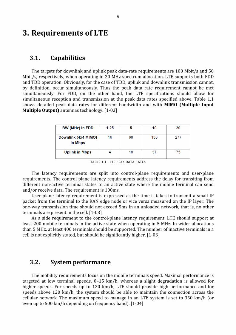
The targets for downlink and uplink peak data-rate requirements are 100 Mbit/s and 50
Mbit/s, respectively, when operating in 20 MHz spectrum allocation. LTE supports both FDD
and TDD operation. Obviously, for the case of TDD, uplink and downlink transmission cannot,
by definition, occur simultaneously. Thus the peak data rate requirement cannot be met
simultaneously. For FDD, on the other hand, the LTE specifications should allow for
simultaneous reception and transmission at the peak data rates specified above. Table 1.1
shows detailed peak data rates for different bandwidth and with MIMO (Multiple Input
Multiple Output) antennas technology. [1-03]
TABLE 1.1 - LTE PEAK DATA RATES
The latency requirements are split into control-plane requirements and user-plane
requirements. The control-plane latency requirements address the delay for transiting from
different non-active terminal states to an active state where the mobile terminal can send
and/or receive data. The requirement is 100ms.
User-plane latency requirement is expressed as the time it takes to transmit a small IP
packet from the terminal to the RAN edge node or vice versa measured on the IP layer. The
one-way transmission time should not exceed 5ms in an unloaded network, that is, no other
terminals are present in the cell. [1-03]
As a side requirement to the control-plane latency requirement, LTE should support at
least 200 mobile terminals in the active state when operating in 5 MHz. In wider allocations
than 5 MHz, at least 400 terminals should be supported. The number of inactive terminals in a
cell is not explicitly stated, but should be significantly higher. [1-03]
3.2. System performance
The mobility requirements focus on the mobile terminals speed. Maximal performance is
targeted at low terminal speeds, 0–15 km/h, whereas a slight degradation is allowed for
higher speeds. For speeds up to 120 km/h, LTE should provide high performance and for
speeds above 120 km/h, the system should be able to maintain the connection across the
cellular network. The maximum speed to manage in an LTE system is set to 350 km/h (or
even up to 500 km/h depending on frequency band). [1-04]
7
Special emphasis is put on the voice service that LTE needs to provide with equal quality
as supported by WCDMA/HSPA. [1-02]
The coverage requirements focus on the cell range (radius) that is the maximum distance
from the cell site to a mobile terminal in the cell. The requirement for non-interference-
limited scenarios is to meet the user throughput, the spectrum efficiency, and the mobility
requirements for cells with up to 5 km cell range. For cells with up to 30 km cell range, a slight
degradation of the user throughput is tolerated and a more significant degradation of the
spectrum efficiency is acceptable relative to the requirements. However, the mobility
requirements should be met. Cell ranges up to 100 km should not be precluded by the
specifications, but no performance requirements are stated in this case. [1-02]
3.3. Spectrum Flexibility
One important part of the LTE requirements in terms of spectrum flexibility is the
possibility to deploy LTE-based radio access in both paired and unpaired spectrum.
Therefore, LTE supports both frequency and time-division-based duplex arrangements.
Frequency Division Duplex (FDD) implies that downlink and uplink transmission take place
in different, sufficiently separated, frequency bands. Time Division Duplex (TDD) implies
that downlink and uplink transmission take place in different, non-overlapping time slots.
Thus, TDD can operate in unpaired spectrum, whereas FDD requires paired spectrum. [1-02]
Related to the possibility to deploy the LTE radio access in different frequency bands is
the possibility of being able to operate LTE with different transmission bandwidths on both
downlink and uplink. The main reason for this is that the amount of spectrum being available
for LTE may vary significantly between different frequency bands and also depending on the
exact situation of the operator.
Furthermore, the possibility to operate in different spectrum allocations gives the
possibility for gradual migration of spectrum from other radio access technologies to LTE. The
basic radio access specification including the physical-layer and protocol specifications,
allows for any transmission bandwidth ranging from roughly 1 MHz up to around 20 MHz.
[1-04]
4. System architecture evolution
The RAN architectures of UMTS and LTE are different. Fundamentally, the reason is not
only the difference in design philosophy of the RAN/CN split, but also the difference of the
radio access technologies and their adopted functions. [1-05]
8
4.1. UMTS radio access network
In essence, one important driver for the UMTS RAN architecture is the macro-diversity
functionality used by the DCH transport channels. Macro-diversity requires an anchor point in
the RAN that splits and combines data flows to and from cells that the terminals are currently
using. Those cells are called the active set of the terminal.
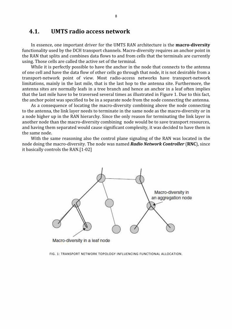
While it is perfectly possible to have the anchor in the node that connects to the antenna
of one cell and have the data flow of other cells go through that node, it is not desirable from a
transport-network point of view. Most radio-access networks have transport-network
limitations, mainly in the last mile, that is the last hop to the antenna site. Furthermore, the
antenna sites are normally leafs in a tree branch and hence an anchor in a leaf often implies
that the last mile have to be traversed several times as illustrated in Figure 1. Due to this fact,
the anchor point was specified to be in a separate node from the node connecting the antenna.
As a consequence of locating the macro-diversity combining above the node connecting
to the antenna, the link layer needs to terminate in the same node as the macro-diversity or in
a node higher up in the RAN hierarchy. Since the only reason for terminating the link layer in
another node than the macro-diversity combining node would be to save transport resources,
and having them separated would cause significant complexity, it was decided to have them in
the same node.
With the same reasoning also the control plane signaling of the RAN was located in the
node doing the macro-diversity. The node was named Radio Network Controller (RNC), since
it basically controls the RAN.[1-02]
FIG. 1: TRANSPORT NETWORK TOPOLOGY INFLUENCING FUNCTIONAL ALLOCATION.
9
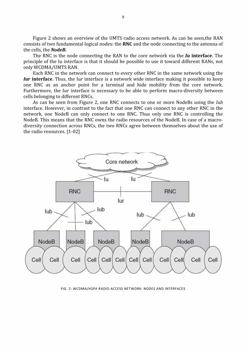
Figure 2 shows an overview of the UMTS radio access network. As can be seen,the RAN
consists of two fundamental logical nodes: the RNC and the node connecting to the antenna of
the cells, the NodeB.
The RNC is the node connecting the RAN to the core network via the Iu interface. The
principle of the Iu interface is that it should be possible to use it toward different RANs, not
only WCDMA/UMTS RAN.
Each RNC in the network can connect to every other RNC in the same network using the
Iur interface. Thus, the Iur interface is a network wide interface making it possible to keep
one RNC as an anchor point for a terminal and hide mobility from the core network.
Furthermore, the Iur interface is necessary to be able to perform macro-diversity between
cells belonging to different RNCs.
As can be seen from Figure 2, one RNC connects to one or more NodeBs using the Iub
interface. However, in contrast to the fact that one RNC can connect to any other RNC in the
network, one NodeB can only connect to one RNC. Thus only one RNC is controlling the
NodeB. This means that the RNC owns the radio resources of the NodeB. In case of a macro-
diversity connection across RNCs, the two RNCs agree between themselves about the use of
the radio resources. [1-02]
FIG. 2: WCDMA/HSPA RADIO ACCESS NETWORK: NODES AND INTERFACES
10
The NodeB is a logical node handling the transmission and reception of a set of cells.
Logically, the antennas of the cells belong to the NodeB but they are not necessarily located at
the same antenna site. For example, in an indoor environment many small cells can be
handled by one NodeB in the basement with the antennas in different corridors on different
floors. With its hardware, the NodeB performs the physical layer functions except for macro-
diversity.
4.1.1. Serving and drift RNC
When specifying where the RAN functionalities should reside, the property of the
WCDMA radio interface made it necessary to have a centralized node handling the macro-
diversity combining and splitting, as well as being in control of the radio resources in multiple
cells. Albeit the NodeB controls a set of cells, the RNC controls several NodeBs and thus a
greater area. Furthermore, the Iur interface makes it possible to have a coordinated approach
in the whole coverage area of the network.
It is only one RNC, the controlling RNC, which is the master of one NodeB. The
controlling RNC sets the frequencies the NodeB shall use in its cells; it allocates power and
schedules the common channels of the cells of the NodeB; and it configures what codes that
shall be used for HS-DSCH and the maximum power used. Furthermore, the controlling RNC is
the RNC deciding whether a user is allowed to use the radio resources in a cell belonging to
one of its NodeBs and in that case which radio resource. These are tasks not directly related to
any user in particular, but to the configurations of the cells.
When a user makes access to the UMTS RAN, it accesses one cell controlled by one NodeB.
The NodeB in its turn are controlled by one RNC, the controlling RNC of that NodeB and cell.
This controlling RNC will be the RNC terminating the RAN-related control and user planes for
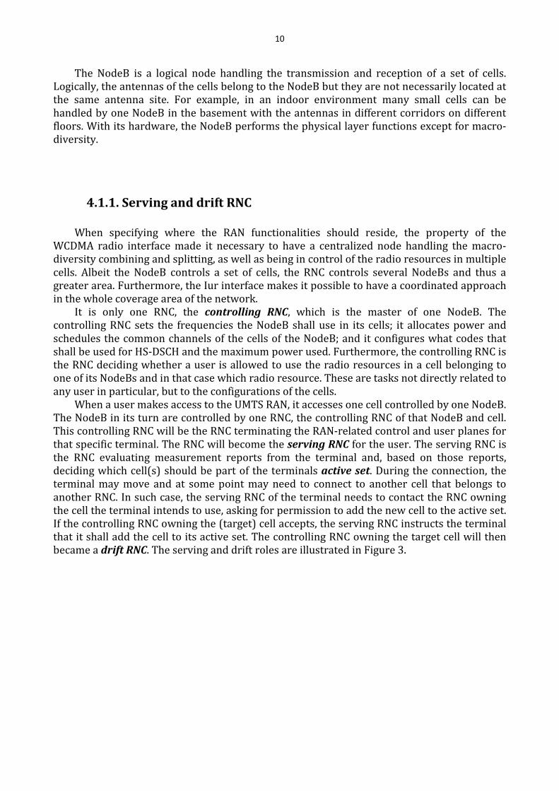
that specific terminal. The RNC will become the serving RNC for the user. The serving RNC is
the RNC evaluating measurement reports from the terminal and, based on those reports,
deciding which cell(s) should be part of the terminals active set. During the connection, the
terminal may move and at some point may need to connect to another cell that belongs to
another RNC. In such case, the serving RNC of the terminal needs to contact the RNC owning
the cell the terminal intends to use, asking for permission to add the new cell to the active set.
If the controlling RNC owning the (target) cell accepts, the serving RNC instructs the terminal
that it shall add the cell to its active set. The controlling RNC owning the target cell will then
became a drift RNC. The serving and drift roles are illustrated in Figure 3.
11
4.2. LTE radio access network
3GPP has introduced UMTS RAN architecture migration steps toward a flatter
architecture. One simple way is to move the complete RNC to the NodeB.
At the time of adopting the single-node architecture for LTE, the function of macro-
diversity was heavily discussed in 3GPP. Although it is technically possible to place the macro-
diversity functionality in the corresponding LTE node to a UMTS NodeB, the eNodeB, and
have one of those nodes as an anchor, the fundamental need for macro-diversity for LTE was
questioned. Quite quickly it was decided that downlink macro-diversity is not needed for
unicast traffic but the uplink was heavily debated. In the end it was decided that uplink
macro-diversity does not give the gains for LTE that motivates the complexity increase.
Thus, macro-diversity between eNodeBs is not supported in LTE. At first, it may seem
obvious to move all the RAN functionality to the eNodeB when not supporting macro-
diversity. However, terminal mobility needs to be considered as well. There are basically two
issues with mobility that need attention: guarantee of no loss of data when changing cell and
minimizing the core network impact when changing cell.
For LTE, the latter was not considered as a major problem; proper design of the core
network will solve the issue. The former was, however, a more difficult problem to solve. It
was in fact agreed that having a centralized anchor with a retransmission layer outside the
eNodeB would make it easier for mobility. However, 3GPP decided that the added complexity
with not having the anchor was better than requiring a node with RAN functionality outside
the eNodeB.
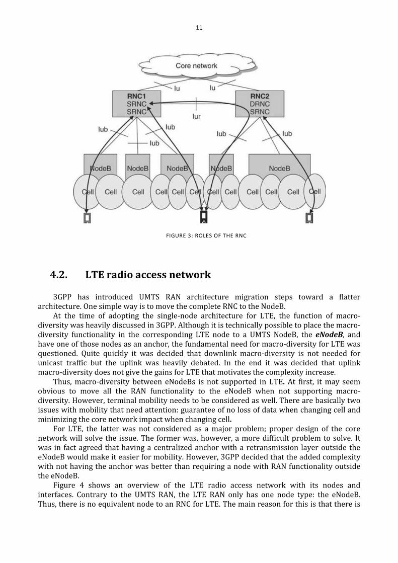
Figure 4 shows an overview of the LTE radio access network with its nodes and
interfaces. Contrary to the UMTS RAN, the LTE RAN only has one node type: the eNodeB.
Thus, there is no equivalent node to an RNC for LTE. The main reason for this is that there is
FIGURE 3: ROLES OF THE RNC
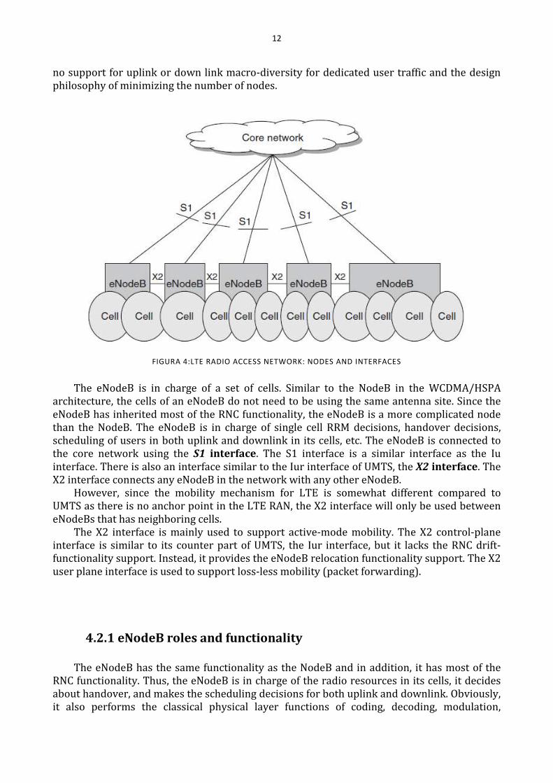
12
no support for uplink or down link macro-diversity for dedicated user traffic and the design
philosophy of minimizing the number of nodes.
FIGURA 4:LTE RADIO ACCESS NETWORK: NODES AND INTERFACES
The eNodeB is in charge of a set of cells. Similar to the NodeB in the WCDMA/HSPA
architecture, the cells of an eNodeB do not need to be using the same antenna site. Since the
eNodeB has inherited most of the RNC functionality, the eNodeB is a more complicated node
than the NodeB. The eNodeB is in charge of single cell RRM decisions, handover decisions,
scheduling of users in both uplink and downlink in its cells, etc. The eNodeB is connected to
the core network using the S1 interface. The S1 interface is a similar interface as the Iu
interface. There is also an interface similar to the Iur interface of UMTS, the X2 interface. The
X2 interface connects any eNodeB in the network with any other eNodeB.
However, since the mobility mechanism for LTE is somewhat different compared to
UMTS as there is no anchor point in the LTE RAN, the X2 interface will only be used between
eNodeBs that has neighboring cells.
The X2 interface is mainly used to support active-mode mobility. The X2 control-plane
interface is similar to its counter part of UMTS, the Iur interface, but it lacks the RNC drift-
functionality support. Instead, it provides the eNodeB relocation functionality support. The X2
user plane interface is used to support loss-less mobility (packet forwarding).
4.2.1 eNodeB roles and functionality
The eNodeB has the same functionality as the NodeB and in addition, it has most of the
RNC functionality. Thus, the eNodeB is in charge of the radio resources in its cells, it decides
about handover, and makes the scheduling decisions for both uplink and downlink. Obviously,
it also performs the classical physical layer functions of coding, decoding, modulation,
13
demodulation, interleaving, de-interleaving, etc. Furthermore, the eNodeB hosts the two layer
retransmission mechanisms; the hybrid ARQ and an outer ARQ.
Since the handover mechanism of LTE is different from WCDMA/UMTS, there is no other
role of the eNodeB than serving eNodeB. The serving eNodeB is the eNodeB that serves the
terminal. The concepts of controlling and drift do not exist. Instead the handover is done by
means of eNodeB relocations.
4.3. SAE Architecture Baseline
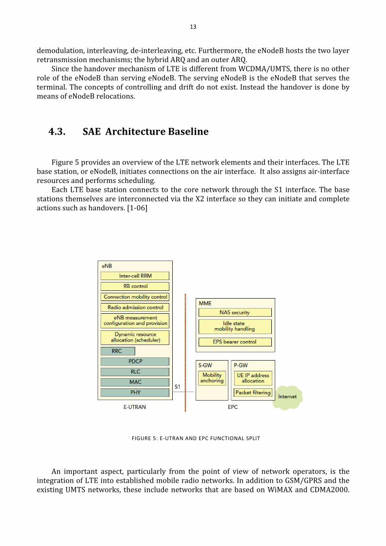
Figure 5 provides an overview of the LTE network elements and their interfaces. The LTE
base station, or eNodeB, initiates connections on the air interface. It also assigns air-interface
resources and performs scheduling.
Each LTE base station connects to the core network through the S1 interface. The base
stations themselves are interconnected via the X2 interface so they can initiate and complete
actions such as handovers. [1-06]
An important aspect, particularly from the point of view of network operators, is the
integration of LTE into established mobile radio networks. In addition to GSM/GPRS and the
existing UMTS networks, these include networks that are based on WiMAX and CDMA2000.
FIGURE 5: E-UTRAN AND EPC FUNCTIONAL SPLIT
14
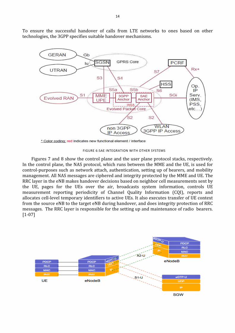
To ensure the successful handover of calls from LTE networks to ones based on other
technologies, the 3GPP specifies suitable handover mechanisms.
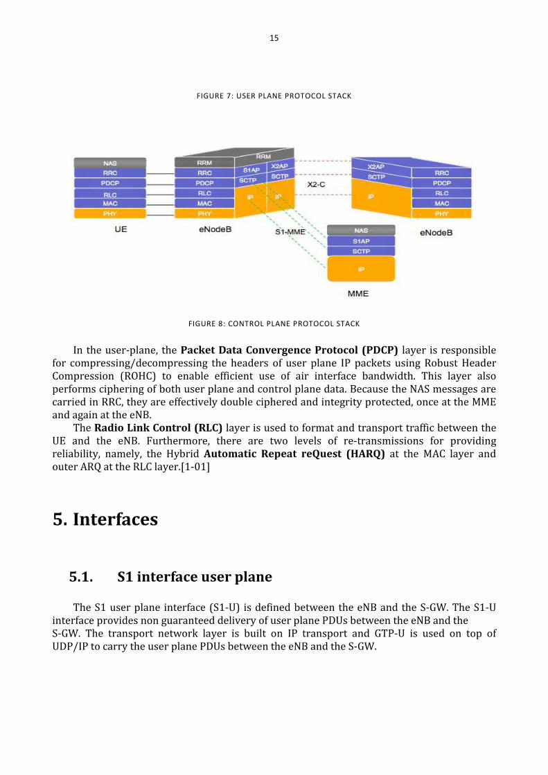
Figures 7 and 8 show the control plane and the user plane protocol stacks, respectively.
In the control plane, the NAS protocol, which runs between the MME and the UE, is used for
control-purposes such as network attach, authentication, setting up of bearers, and mobility
management. All NAS messages are ciphered and integrity protected by the MME and UE. The
RRC layer in the eNB makes handover decisions based on neighbor cell measurements sent by
the UE, pages for the UEs over the air, broadcasts system information, controls UE
measurement reporting periodicity of Channel Quality Information (CQI), reports and
allocates cell-level temporary identifiers to active UEs. It also executes transfer of UE context
from the source eNB to the target eNB during handover, and does integrity protection of RRC
messages. The RRC layer is responsible for the setting up and maintenance of radio bearers.
[1-07]
FIGURE 6:SAE INTEGRATION WITH OTHER SYSTEMS
15
FIGURE 7: USER PLANE PROTOCOL STACK
FIGURE 8: CONTROL PLANE PROTOCOL STACK
In the user-plane, the Packet Data Convergence Protocol (PDCP) layer is responsible
for compressing/decompressing the headers of user plane IP packets using Robust Header
Compression (ROHC) to enable efficient use of air interface bandwidth. This layer also
performs ciphering of both user plane and control plane data. Because the NAS messages are
carried in RRC, they are effectively double ciphered and integrity protected, once at the MME
and again at the eNB.
The Radio Link Control (RLC) layer is used to format and transport traffic between the
UE and the eNB. Furthermore, there are two levels of re-transmissions for providing
reliability, namely, the Hybrid Automatic Repeat reQuest (HARQ) at the MAC layer and
outer ARQ at the RLC layer.[1-01]
5. Interfaces
5.1. S1 interface user plane
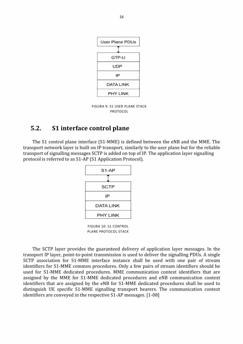
The S1 user plane interface (S1-U) is defined between the eNB and the S-GW. The S1-U
interface provides non guaranteed delivery of user plane PDUs between the eNB and the
S-GW. The transport network layer is built on IP transport and GTP-U is used on top of
UDP/IP to carry the user plane PDUs between the eNB and the S-GW.
16
5.2. S1 interface control plane
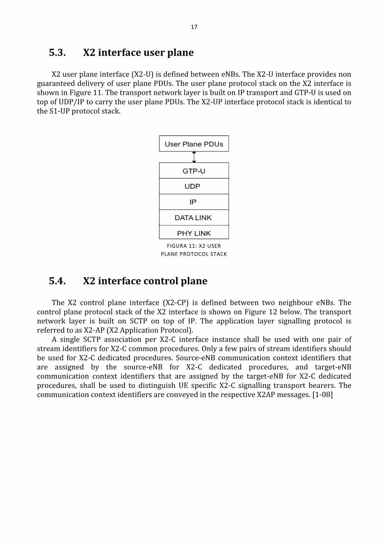
The S1 control plane interface (S1-MME) is defined between the eNB and the MME. The
transport network layer is built on IP transport, similarly to the user plane but for the reliable
transport of signalling messages SCTP is added on top of IP. The application layer signalling
protocol is referred to as S1-AP (S1 Application Protocol).
The SCTP layer provides the guaranteed delivery of application layer messages. In the
transport IP layer, point-to-point transmission is used to deliver the signalling PDUs. A single
SCTP association for S1-MME interface instance shall be used with one pair of stream
identifiers for S1-MME common procedures. Only a few pairs of stream identifiers should be
used for S1-MME dedicated procedures. MME communication context identifiers that are
assigned by the MME for S1-MME dedicated procedures and eNB communication context
identifiers that are assigned by the eNB for S1-MME dedicated procedures shall be used to
distinguish UE specific S1-MME signalling transport bearers. The communication context
identifiers are conveyed in the respective S1-AP messages. [1-08]
FIGURA 9: S1 USER PLANE STACK
PROTOCOL
FIGURA 10: S1 CONTROL
PLANE PROTOCOL STACK
17
5.3. X2 interface user plane
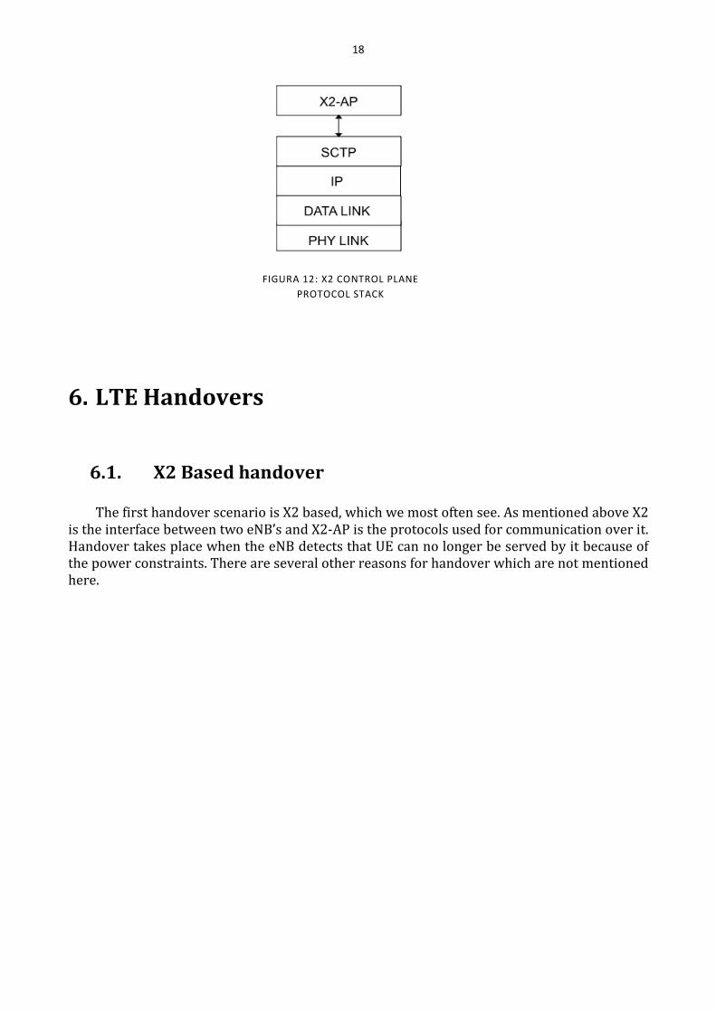
X2 user plane interface (X2-U) is defined between eNBs. The X2-U interface provides non
guaranteed delivery of user plane PDUs. The user plane protocol stack on the X2 interface is
shown in Figure 11. The transport network layer is built on IP transport and GTP-U is used on
top of UDP/IP to carry the user plane PDUs. The X2-UP interface protocol stack is identical to
the S1-UP protocol stack.
5.4. X2 interface control plane
The X2 control plane interface (X2-CP) is defined between two neighbour eNBs. The
control plane protocol stack of the X2 interface is shown on Figure 12 below. The transport
network layer is built on SCTP on top of IP. The application layer signalling protocol is
referred to as X2-AP (X2 Application Protocol).
A single SCTP association per X2-C interface instance shall be used with one pair of
stream identifiers for X2-C common procedures. Only a few pairs of stream identifiers should
be used for X2-C dedicated procedures. Source-eNB communication context identifiers that
are assigned by the source-eNB for X2-C dedicated procedures, and target-eNB
communication context identifiers that are assigned by the target-eNB for X2-C dedicated
procedures, shall be used to distinguish UE specific X2-C signalling transport bearers. The
communication context identifiers are conveyed in the respective X2AP messages. [1-08]
FIGURA 11: X2 USER
PLANE PROTOCOL STACK
18
6. LTE Handovers
6.1. X2 Based handover
The first handover scenario is X2 based, which we most often see. As mentioned above X2
is the interface between two eNB’s and X2-AP is the protocols used for communication over it.
Handover takes place when the eNB detects that UE can no longer be served by it because of
the power constraints. There are several other reasons for handover which are not mentioned
here.
FIGURA 12: X2 CONTROL PLANE
PROTOCOL STACK
19
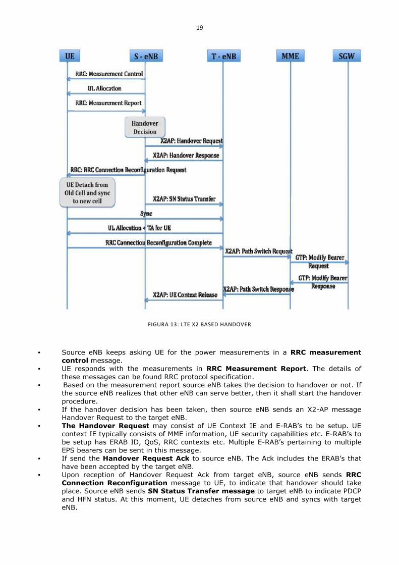
FIGURA 13: LTE X2 BASED HANDOVER
• Source eNB keeps asking UE for the power measurements in a RRC measurement
control message.
• UE responds with the measurements in RRC Measurement Report. The details of
these messages can be found RRC protocol specification.
• Based on the measurement report source eNB takes the decision to handover or not. If
the source eNB realizes that other eNB can serve better, then it shall start the handover
procedure.
• If the handover decision has been taken, then source eNB sends an X2-AP message
Handover Request to the target eNB.
• The Handover Request may consist of UE Context IE and E-RAB’s to be setup. UE
context IE typically consists of MME information, UE security capabilities etc. E-RAB’s to
be setup has ERAB ID, QoS, RRC contexts etc. Multiple E-RAB’s pertaining to multiple
EPS bearers can be sent in this message.
• If send the Handover Request Ack to source eNB. The Ack includes the ERAB’s that
have been accepted by the target eNB.
• Upon reception of Handover Request Ack from target eNB, source eNB sends RRC
Connection Reconfiguration message to UE, to indicate that handover should take
place. Source eNB sends SN Status Transfer message to target eNB to indicate PDCP
and HFN status. At this moment, UE detaches from source eNB and syncs with target
eNB.
20
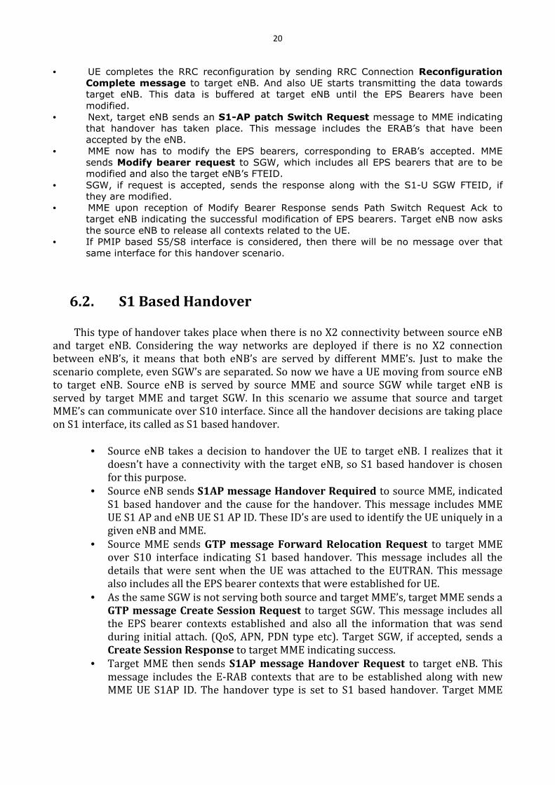
• UE completes the RRC reconfiguration by sending RRC Connection Reconfiguration
Complete message to target eNB. And also UE starts transmitting the data towards
target eNB. This data is buffered at target eNB until the EPS Bearers have been
modified.
• Next, target eNB sends an S1-AP patch Switch Request message to MME indicating
that handover has taken place. This message includes the ERAB’s that have been
accepted by the eNB.
• MME now has to modify the EPS bearers, corresponding to ERAB’s accepted. MME
sends Modify bearer request to SGW, which includes all EPS bearers that are to be
modified and also the target eNB’s FTEID.
• SGW, if request is accepted, sends the response along with the S1-U SGW FTEID, if
they are modified.
• MME upon reception of Modify Bearer Response sends Path Switch Request Ack to
target eNB indicating the successful modification of EPS bearers. Target eNB now asks
the source eNB to release all contexts related to the UE.
• If PMIP based S5/S8 interface is considered, then there will be no message over that
same interface for this handover scenario.
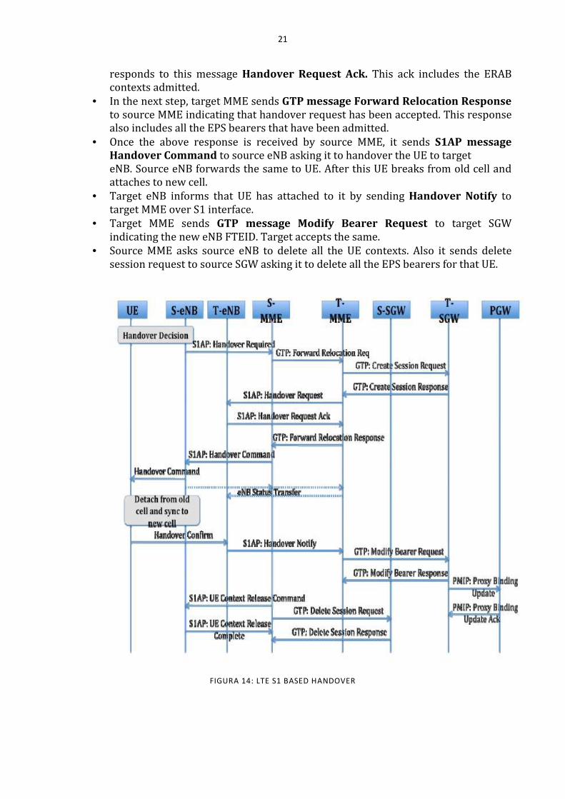
6.2. S1 Based Handover
This type of handover takes place when there is no X2 connectivity between source eNB
and target eNB. Considering the way networks are deployed if there is no X2 connection
between eNB’s, it means that both eNB’s are served by different MME’s. Just to make the
scenario complete, even SGW’s are separated. So now we have a UE moving from source eNB
to target eNB. Source eNB is served by source MME and source SGW while target eNB is
served by target MME and target SGW. In this scenario we assume that source and target
MME’s can communicate over S10 interface. Since all the handover decisions are taking place
on S1 interface, its called as S1 based handover.
• Source eNB takes a decision to handover the UE to target eNB. I realizes that it
doesn’t have a connectivity with the target eNB, so S1 based handover is chosen
for this purpose.
• Source eNB sends S1AP message Handover Required to source MME, indicated
S1 based handover and the cause for the handover. This message includes MME
UE S1 AP and eNB UE S1 AP ID. These ID’s are used to identify the UE uniquely in a
given eNB and MME.
• Source MME sends GTP message Forward Relocation Request to target MME
over S10 interface indicating S1 based handover. This message includes all the
details that were sent when the UE was attached to the EUTRAN. This message
also includes all the EPS bearer contexts that were established for UE.
• As the same SGW is not serving both source and target MME’s, target MME sends a
GTP message Create Session Request to target SGW. This message includes all
the EPS bearer contexts established and also all the information that was send
during initial attach. (QoS, APN, PDN type etc). Target SGW, if accepted, sends a
Create Session Response to target MME indicating success.
• Target MME then sends S1AP message Handover Request to target eNB. This
message includes the E-RAB contexts that are to be established along with new
MME UE S1AP ID. The handover type is set to S1 based handover. Target MME
21
responds to this message Handover Request Ack. This ack includes the ERAB
contexts admitted.
• In the next step, target MME sends GTP message Forward Relocation Response
to source MME indicating that handover request has been accepted. This response
also includes all the EPS bearers that have been admitted.
• Once the above response is received by source MME, it sends S1AP message
Handover Command to source eNB asking it to handover the UE to target
eNB. Source eNB forwards the same to UE. After this UE breaks from old cell and
attaches to new cell.
• Target eNB informs that UE has attached to it by sending Handover Notify to
target MME over S1 interface.
• Target MME sends GTP message Modify Bearer Request to target SGW
indicating the new eNB FTEID. Target accepts the same.
• Source MME asks source eNB to delete all the UE contexts. Also it sends delete
session request to source SGW asking it to delete all the EPS bearers for that UE.
FIGURA 14: LTE S1 BASED HANDOVER
22
7. Conclusions
Beginning from an introduction of the wireless cellular generation deployed over the
years from 80s until now we have shown new specifications under the latest improvement in
mobile telecommunications. After a quick description of the proceedings that brought to
creation of the 3g partnership project we had treated requirements of third generation mobile
technology to further go through the evolution of the pre-existent architecture of the entire
system, stepped upon the system capabilities and performances. Finally we presented some
examples of the handover procedures that are performed through the new interfaces that
connect base stations to each other or to the mobility management entity and allow a flat and
therefore faster access network.
LTE systems will be able to provide connectivity with a lot of other “Non-3GPP”
technologies like 3GPP2 (CDMA2000, WiMAX etc) and WiFi networks giving large possibilities
for coexistence and allowing a continuous mobile access in that places where LTE
infrastructures are not yet deployed. Initial deployments of LTE are expected by 2010 and
commercial availability on a larger scale 1-2 years later.
II. References
[1-01] TECHNICAL WHITE PAPER: Long Term Evolution (LTE): A Technical Overview, Motorola Inc.
[1-02] E.Dahlman, S. Parkvall, J.Skold, P.Beming, “3G Evolution HSPA and LTE for Mobile Broadband” 2nd
Edition Oct 2008, Academic Press.
[1-03] Technical Overview of 3GPP LTE, Hyung G. Myung. May 18, 2008.
[1-04] 3GPP LTE presentation Kyoto May 22rd 2007. 3GPP TSG RAN Chairman (Alcatel-Lucent).
[1-05] LTE and UMTS Terminology and Concepts, Chris Reece, Subject Matter Expert - 8/2009. Award
Solutions.
[1-06] “Protocol Stack Testing for LTE, Effective test strategies can help transform UMTS into a cellular
wideband system”, Christina Geßner, Rohde & Schwarz. www.tmworld.com. 14-12-09
[1-07] “LTE E-UTRAN and its Access Side Protocols”, Suyash Tripathi, Vinay Kulkarni, and Alok Kumar,
Continuous Computing. http://www.ccpu.com/papers/lte-eutran. 14-12-09.
[1-08] 3GPP TS 36.300 V9.1.0 (2009-09), Technical Specification Release 9. www.3gpp.org. 14-12-09.
[1-09] LTE Whitepaper – Santosh Kumar Dornal. http://wired-n-wireless.blogspot.com 26. 14-12-09