Embed Size (px)
Citation preview
M-Series Model MG Digital Transmitter
Magnetostrictive Liquid-Level Transmitters with Temposonics® Technology
Level Plus®
OPERATION AND INSTALLATION MANUAL
The Measurable Difference

MTS SensorsLevel Plus® Liquid-Level Transmitters M-Series Model MG Digital Transmitter Operation and Installation Manual, Document Number: 550791 Revision L (KOR) 03/2014

MTS SensorsLevel Plus® Liquid-Level Transmitters M-Series Model MG Digital Transmitter
Operation and Installation Manual, Document Number: 550791 Revision L (KOR) 03/2014
GERMANY
GENERAL:
Tel.: +49-2351-9587-0Fax: +49-2351-56491e-mail: [email protected]://www.mtssensor.de
MAILING AND SHIPPING ADDRESS:
MTS Sensor Technologie, GmbH & Co. KGAuf dem Schüffel 9D - 58513 Lüdenscheid, Germany
TECHNICAL SUPPORT AND APPLICATIONS:
Tel.: +49-2351-9587-0e-mail: [email protected]://www.mtssensor.de
JAPAN
GENERAL:
Tel.: +81-42-775-3838Fax: +81-42-775-5516 e-mail: [email protected]://www.mtssensor.co.jp
MAILING AND SHIPPING ADDRESS:
MTS Sensors Technology Corporation737 Aihara-machi, Machida-shiTokyo 194-0211, Japan
TECHNICAL SUPPORT AND APPLICATIONS:
Tel.: +81-42-775-3838Fax: +81-42-775-5512
GENERAL:
Tel: +1-919-677-0100Fax: +1-919-677-2343E-mail: [email protected]://www.mtssensors.com
MAILING AND SHIPPING ADDRESS:
MTS Systems CorporationSensors Division3001 Sheldon DriveCary, North Carolina, 27513, USA
CUSTOMER SERVICE:
Tel: +1-800-457-6620Fax: +1-800-498-4442E-mail: [email protected]
TECHNICAL SUPPORT AND APPLICATIONS:
24 Hour Emergency Technical SupportTel: +1-800-633-7609e-mail: [email protected]
UNITED STATES
OFFICE HOURS (EST):
Monday - Thursday: 8:00 a.m. to 5:00 p.m.Friday: 8:00 a.m. to 4:00 p.m.
REMITTANCE ADDRESS:
MTS Systems CorporationSensors DivisionNW 5872 P.O. Box 1450Minneapolis, MN, 55486-5872
QUOTE AND CONTRACT TERMS & CONDITIONS:
The parties expressly agree that the purchase and use of Material and/or Services from MTS Sensors Division are subject to MTS’ Terms and Conditions, in effect as of the date of this document, which are located at http://www.mtssensors.com/fileadmin/media/pdfs/Terms_and_Condi-tions.pdf and are incorporated by reference into this and any ensuing contract. Printed Terms and Conditions can be provided upon request by emailing [email protected] or if you prefer, go to http://www.mts-sensors.com/index and click the Quote/Contract Terms and Conditions link at the bottom of the page to download the PDF.
i
Model MG Operation and Installation ManualContact Information
Cont
act
Info
rmat
ion
MTS SensorsLevel Plus® Liquid-Level Transmitters M-Series Model MG Digital Transmitter Operation and Installation Manual, Document Number: 550791 Revision L (KOR) 03/2014
Notices used in this manual
This manual contains notices to highlight specific information as follows:
Notes:
These notices provide important tips, guidance, or advice.
Important:
These notices provide information that might help you avoid inconvenient or problem situations.
Attention:
These notices indicate possible damage to programs, devices, or data and is placed justbefore the instruction or situation in which damage could occur.
Caution:
These notices indicate situations that can be potentially hazardous to you. A Caution notice is placed justbefore a description of a potentially hazardous procedure, step, or situation.
Related publications
The following publications are listed below by part number followed by description and are available in Adobe Acrobat Portable Document Format (PDF) at http://www.mtssensors.com/. Note: The following documents are available only in English.
550784 - Product Specification, Level Plus M-Series Digital 551103 - Level Plus Accessories Catalog551104 - Component Replacement Guide550907 - Application Datasheet Rigid550908 - Application Datasheet Sanitary550909 - Application Datasheet 7/8” Flex551410 - Brief Operation Manual for Safe Use
How this manual is organized
“Introduction”, provides an overview of the manual. “Terms and Definitions”, provides definitions of terms used in this manual.“Product Overview”, gives an overall product description for the Level Plus liquid-level transmitter, its specifications, use, output, and electronics.“Installation and Mounting”, provides detailed installation and mounting information.“Electrical Connections and Wiring Procedures”, provides engineering specifications and wiring diagrams to assist in the installation process.“Maintenance and Field Service”, provides guidelines for general maintenance and procedures for replacing the Model MG electronic module or level transmitter.“Troubleshooting”, provides a list of symptoms, their possible cause and the action to be taken when troubleshooting the transmitter.“Quick Start-Up Guide, (Modbus and DDA)”, provides a list of steps to quickly set up your Modbus or DDA output.“Modbus Interface”, provides information to communicate via the Modbus RTU protocol.“Foundation™ fieldbus Interface”, provides information to communicate via the Foundation™ fieldbus protocol.“DDA Protocol”, provides the DDA hardware and software environment overviews.“Agency Information” provides comprehensive listings of agency approvals and stan-dards, installation drawings, labels and applicable protocols.
Getting information, help, and service
You can get the latest ordering information and software updates by visiting www.mtssensors.com websiteGeneral contact information, shipping and office hours are available on page i.
ii
Model MG Operation and Installation ManualReference Information
Refe
renc
eIn
form
atio
n

MTS SensorsLevel Plus® Liquid-Level Transmitters M-Series Model MG Digital Transmitter
Operation and Installation Manual, Document Number: 550791 Revision L (KOR) 03/2014
Contact informationGeneral ........................................................................................ iMailing and shipping address ..................................................... iCustomer service ........................................................................ iTechnical support and applications ............................................. iOffice hours ................................................................................ iRemittance address .................................................................... iQuote and contract terms and conditions .................................... i
Reference informationNotices used in this manual ........................................................ iiRelated publications .................................................................... iiHow this manual is organized ..................................................... iiGetting information, help, and service ........................................ ii
IntroductionIntroduction ............................................................... 1Public website support portal ......................................... 1
Terms and DefinitionsTerms and definitions reference ...................................... 2
Model MG product overviewProduct overview ........................................................ 4
Industries .................................................................................... 4 Applications ................................................................................ 4 Features ...................................................................................... 4
Components .............................................................. 4Housings ..................................................................................... 4Outer pipe configurations ........................................................... 5Floats ......................................................................................... 6Internal electronics ...................................................................... 6Accessories ................................................................................ 6
Theory of operation ...................................................... 7Accuracy ................................................................. 7Warranty ................................................................. 7Model number identification ........................................... 8
KC ...............................................................................................8Product specifications ................................................. 10
Model MG transmitter installation and mountingInstallation and mounting ............................................ 11Storage ................................................................. 11Stilling wells and guide poles ....................................... 11Installation............................................................... 11
Rigid probe ............................................................................... 11Flexible probe ........................................................................... 12
Mounting ................................................................ 13Threaded flange mounting ......................................................... 13Welded flange mounting .......................................................... 13 Sanitary Tri-Clamp mounting ................................................... 14
Electrical connections and wiringElectrical connections and wiring procedures ..................... 15Safety recommendations for installation ........................... 15Industrial topologies .................................................. 15
Point-to-point ........................................................................... 15Bus with spurs .......................................................................... 15 Tree .... ...................................................................................... 15
Daisy chain .............................................................................. 15Recommended cable types ........................................... 16
Cable recommendation for Modbus and DDA .......................... 16Cable recommendation for FOUNDATION™ fieldbus .................. 16
Electrical conduit installation ........................................ 16Grounding ............................................................... 17
Maintenance and field serviceMaintenance and field service ....................................... 18General maintenance and field service requirements ........... 18
Float maintenance .................................................................... 18Field service ............................................................................. 18Service / RMA policy ................................................................ 18
TroubleshootingTroubleshooting procedures ......................................... 19
Software installation and user interface referencesQuick start-up guide (Modbus and DDA) ........................... 20
Before you begin ...................................................................... 20Quick start-up procedure ......................................................... 20
Modbus user interfaceModbus interface ...................................................... 21
Modbus implementation .......................................................... 21Modbus function codes ........................................................... 21Device Modbus register maps .................................................. 22Special/Advanced diagnostic register maps ............................. 26How units are used .................................................................. 26Modbus register Map note references ..................................... 26
Formulas used in volume calculation .............................. 30Installing the M-Series digital setup software .................... 31Setting up and calibrating the Model MG digital transmitter ..................................................... 32
Data from Device tab ............................................................... 32Volume Calculations tab ........................................................... 34
FOUNDATION™ fieldbus user interfaceFOUNDATIONTM fieldbus interface ................................... 36Device description ..................................................... 36Transducer block ....................................................... 36Analog input function blocks ......................................... 39Resource block ......................................................... 40LAS/Back-up LAS ....................................................... 40Setup and calibration ................................................. 40FOUNDATIONTM fieldbus handheld menu tree ..................... 41
DDA user interfaceDDA interface ........................................................... 42Hardware and software environments .............................. 42DDA command decoder examples .................................. 43DDA/Host computer communication protocol ..................... 43
Network protocol/timing considerations .................................. 45
iii
Model MG Operation and Installation ManualTable of Contents
Tabl
e of
Co
nten
ts

MTS SensorsLevel Plus® Liquid-Level Transmitters M-Series Model MG Digital Transmitter Operation and Installation Manual, Document Number: 550791 Revision L (KOR) 03/2014 iv
DDA user interface (Continued)DDA command definitions (includes protocol information) ................................... 46
Special control commands ....................................................... 46Level commands ...................................................................... 47Temperature commands .......................................................... 47Multiple output commands ...................................................... 48High-level memory read commands ........................................ 49High-level memory writing commands .................................... 50Diagnostic/Special command set ............................................. 52DDA Error codes ...................................................................... 52
M-Series digital setup software installation, setup and calibration ............................................................. 53
Data from device tab ................................................................ 53
Agency InformationAgency approvals ...................................................... 55KC ........................................................................ 55Hazardous area installation .......................................... 55
KC for Modbus and DDA .......................................................... 56Installation drawings ............................................................. 56Notes .................................................................................... 57Wiring connections ............................................................... 59Labels ................................................................................... 60Special Condition for Use ..................................................... 61
KC for FOUNDATIONTM fieldbus ............................................... 62Installation drawing .............................................................. 62Notes .................................................................................... 63Wiring connections ............................................................... 64Labels ................................................................................... 65Special Condition for Use ..................................................... 66
KC certificates ........................................................... 67
Model MG Operation and Installation ManualTable of Contents
Tabl
e of
Co
nten
ts

MTS SensorsLevel Plus® Liquid-Level Transmitters M-Series Model MG Digital Transmitter
Operation and Installation Manual, Document Number: 550791 Revision L (KOR) 03/2014
Introduction
MTS is recognized as the pioneer, innovator and leader in magnetostrictive sensing. The new Level Plus® M-Series transmitter design repre-sents a continuation of our on-going effort to provide effective, innovative and reliable products to the Liquid Level marketplace.
This manual will provide the following information about the Level Plus Model MG digital transmitter:
• Terms and definitions• Product overview• Installation and mounting• Electrical connections and wiring procedures• Maintenance and field service• Troubleshooting• Quick start-up guide (Modbus and DDA)• Modbus interface• FOUNDATION™ fieldbus interface• DDA interface• Product certification
Public website support portal
Visit our support portal at http://www.mtssensors.com for:
• Building Level Plus M-Series model numbers• Latest documentation releases• Detailed ordering information• Latest software updates
1
Model MG Operation and Installation ManualIntroduction
Intro
duct
ion

MTS SensorsLevel Plus® Liquid-Level Transmitters M-Series Model MG Digital Transmitter Operation and Installation Manual, Document Number: 550791 Revision L (KOR) 03/2014 2
Terms and definitions reference
I
Interface – Noun; The measurement of the level of one liquid when that liquid is below another liquid.
Interface – Adj.; The Software Graphical User Interface (GUI) that allows the user to access software protocols (DDA, MODBUS).
Intrinsic safety – ‘Intrinsically safe’ - Type of protection based on the restriction of electrical energy within apparatus of interconnecting wiring exposed to potentially explosive atmosphere to a level below that which can cause ignition by either sparking or heating effects.
M
Mass – The property of a body that causes it to have weight in a gravitational field, calculated by density at the reference temperature multiplied by the volume correction factor (Density * VCF).
MODBUS - A serial communications protocol published by Modicon in 1979 for use with its programmable logic controllers (PLCs). It has become a de facto standard communications protocol in industry, and is now the most commonly available means of connecting industrial electronic devices.
N
NEMA Type 4X – A product Enclosure intended for indoor or outdoor use primarily to provide a degree of protection against corrosion, windblown dust and rain, splashing water, and hose-directed water; and to be undamaged by the formation of ice on the enclosure. They are not intended to provide protection against conditions such as internal condensation or internal icing.
NPT – U.S. standard defining tapered pipe threads used to join pipes and fittings.
NSVP – ‘Net Standard Volume of the Product’ – The temperature corrected volume for the product liquid in the tank, requires the transmitter to be ordered with temperature measurement capabilities. The NSVP is calculated by multiplying the volume of the product liquid by a volume correction factor based on temperature (GOVP * VCF).
R
Reference Temperature – The temperature at which the density measurement is given, the allowable values are 32 °F to 150 °F.
S
Specific Gravity – The density ratio of a liquid to the density of water at the same conditions.
Sphere Radius – The internal radius of the sphere that contains the liquid, the value is used to calculate the volume along with the Sphere Offset.
Sphere Offset – An offset value that accounts for additional volume in a sphere from non-uniform sphere geometry, the value is used to calculate the volume along with the Sphere Radius.
Strap Table – A table of measurement correlating the height of a ves-
6A Heavy Oils – ‘Generalized Crude Oils’, Correction of Volume to 60 °F against API Gravity.
6B Light Oils – ‘Generalized Products’, Correction of Volume to 60 °F against API Gravity.
6C Chemical – ‘Volume Correction Factors (VCF)’ for individual and special applications, volume correction to 60 °F against thermal expansion coefficients.
6C Mod – An adjustable temperature reference for defining VCF.
A
API Gravity – The measure of how heavy or light a petroleum liquid is compared to water. Allowable values are 0 to 100 degrees API for (6A) and 0 to 85 degrees API for (6B).
D
DDA – ‘Direct Digital Access’ – The proprietary digital protocol developed by MTS for use in intrinsically safe areas.
Density – Mass divided by the volume of an object at a specific tem-perature. The density value should be entered as lb / cu. ft..
F
Flameproof – Type of protection based on enclosure in which the parts which can ignite an explosive gas atmosphere are placed within and which can withstand the pressure developed during an internal explosion of an explosive mixture, and which prevents the transmis-sion of the explosion to the explosive gas atmosphere surrounding the enclosure.
FOUNDATION™ fieldbus – An all digital, serial, two-way communica-tions system that serves as the base-level network in a plant or factory automation environment. Developed and administered by the fieldbus FOUNDATION™.
G
GOVI – ‘Gross Observed Volume of the Interface’ – The total volume of the tank occupied by the interface liquid. The GOVI is only given when measuring two liquids and is calculated by subtracting the volume of the product from the total volume of liquid in the tank (GOVT – GOVP).
GOVP – ‘Gross Observed Volume of the Product’ – The total volume of the tank occupied by the product liquid. When measuring only one liquid, it is also the total volume of liquid in the tank (GOVT). When measuring two liquids it is the total volume of liquid in the tank minus the volume of the interface liquid (GOVT – GOVI).
GOVT – ‘Total Gross Observed Volume’ – The total volume of liquid in the tank. When measuring only one liquid it is equal to the volume of the product (GOVP). When measuring two liquids it is equal to the volume of the product and interface liquids (GOVP + GOVI).
GOVU – ‘Gross Observed Volume Ullage’ – the difference in volume between the working capacity of a tank and the total volume in the tank (Working Capacity – GOVT).
Term
s an
dDe
finiti
ons
Model MG Operation and Installation ManualTerms and Definitions
MTS SensorsLevel Plus® Liquid-Level Transmitters M-Series Model MG Digital Transmitter
Operation and Installation Manual, Document Number: 550791 Revision L (KOR) 03/20143
sel to the volume that is contained at that height. The transmitter can contain up to 100 points.
T
TEC – ‘Thermal Expansion Coefficient’ - a value correlating the change in temperature for an object with the change in its volume. Allowable values are 270.0 to 930.0. TEC units are in 10 E-6/Deg F.
Temperature Correction Method – One of five product correction methods used to correct the product volume in the tank due to changes in temperature from 60 °F including (6A, 6B, 6C, 6C Mod, and Custom Table.
V
Volume Calculation Mode – One of two methods use to calculate volume measurements from level measurements, including Sphere and Strap Table.
VCF – ‘Volume Correction Factor’ – A table of measurements correlating temperature points with correction factors for the liquids expansion/contraction. The transmitter can contain up to 50 points.
W
Working Capacity – The maximum volume of liquid that the user desires for their vessel to hold, typically 80% of the vessels maximum volume before overfill.
Model MG Operation and Installation ManualTerms and Definitions
Term
s an
dDe
finiti
ons

MTS SensorsLevel Plus® Liquid-Level Transmitters M-Series Model MG Digital Transmitter Operation and Installation Manual, Document Number: 550791 Revision L (KOR) 03/2014 4
Product overview
The Level Plus Model MG Liquid-Level transmitter is a continuous multi-functional magnetostrictive transmitter that provides product level, interface level, and temperature to the user via Modbus, DDA, or FOUNDATION™ fieldbus output. Magnetostrictive technology is one of the most accurate and repeatable level technologies available to date. MTS is the inventor and purveyor of magnetostrictive technology and has been serving the level industry for over 30 years.
INDUSTRIES APPLICATIONS FEATURES
Petroleum Liquid petroleum gas Pharmaceutical Food & beverage Chemical Wastewater
Tank farms Terminals Bullet tanks Spheres Separator tanks Battery tanks Storage tanks
3-in-1 measurement - Product level- Interface level- Temperature level
100 Point strap table No scheduled maintenance or recalibration API temperature corrected volumes Non-linearity 0.008% F.S. Field repairable
Components
The Level Plus Model MG liquid level transmitter consists of four main components; a housing, outer pipe, float, and electronics. Varying the components of the transmitter allows the transmitter to be customized to almost any application.
HOUSINGS
Level Plus Model MG transmitters are available in three housing configurations; NEMA Type 4X 316L stainless steel, flameproof single and dual-cavity housings as shown below:
NEMA Type 4X 316L stainless-steel housingTop View
123 mm(4.85 in.) O.D.
81 mm(3.19 in.)
152 mm(6 in.)
½ in. NPT conduit access
Single cavity flameproof housing
123 mm(4.84 in.)
3/4 in. NPTconduit accessM20x1.5 (ATEX)
127 mm(5 in.)
210 mm(8.25 in.) max.121 mm
(4.75 in.) O.D.
Dual cavity flameproof housing
127 mm(5 in.)
210 mm(8.25 in.) max.
121 mm(4.75 in.)
O.D.
177 mm(6.95 in.)
81 mm(3.18 in.)
3/4 in. NPTconduit access
M20x1.5(ATEX)
Prod
uct
Over
view
Model MG Operation and Installation ManualProduct Overview
MTS SensorsLevel Plus® Liquid-Level Transmitters M-Series Model MG Digital Transmitter
Operation and Installation Manual, Document Number: 550791 Revision L (KOR) 03/20145
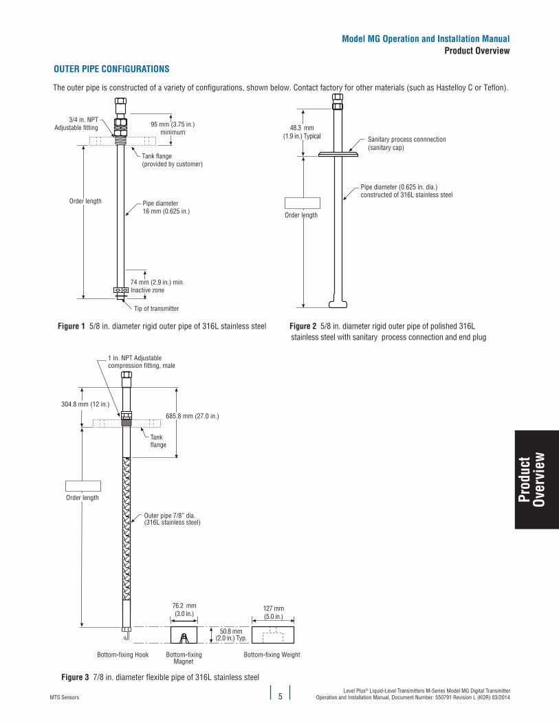
OUTER PIPE CONFIGURATIONS
The outer pipe is constructed of a variety of configurations, shown below. Contact factory for other materials (such as Hastelloy C or Teflon).
74 mm (2.9 in.) min.Inactive zone
3/4 in. NPTAdjustable fitting
Tip of transmitter
Tank flange(provided by customer)
Order length
95 mm (3.75 in.)minimum
Pipe diameter16 mm (0.625 in.)
Figure 1 5/8 in. diameter rigid outer pipe of 316L stainless steel
Sanitary process connnection (sanitary cap)
Pipe diameter (0.625 in. dia.)constructed of 316L stainless steel
Order length
48.3 mm(1.9 in.) Typical
Figure 2 5/8 in. diameter rigid outer pipe of polished 316L stainless steel with sanitary process connection and end plug
Order length
Outer pipe 7/8” dia.(316L stainless steel)
304.8 mm (12 in.)
685.8 mm (27.0 in.)
Tankflange
1 in. NPT Adjustablecompression fitting, male
Bottom-fixingMagnet
Bottom-fixing WeightBottom-fixing Hook
76.2 mm(3.0 in.)
127 mm(5.0 in.)
50.8 mm(2.0 in.) Typ.
Figure 3 7/8 in. diameter flexible pipe of 316L stainless steel
Prod
uct
Over
view
Model MG Operation and Installation ManualProduct Overview

MTS SensorsLevel Plus® Liquid-Level Transmitters M-Series Model MG Digital Transmitter Operation and Installation Manual, Document Number: 550791 Revision L (KOR) 03/2014 6
FLOATS
Model MG transmitters offer numerous floats for different applications such as stainless steel, 3-A sanitary, hastelloy, Teflon, and Nitrophyl for both product level and interface level. To be able to accurately detect the interface level there needs to be a difference of at least 0.05 in specific gravities between the product and interface liquids. For detailed information about floats, refer to the ‘Accessories Catalog’, MTS part number 551103.
For assistance with selecting a specific float for your application, please contact Technical Support with the following information:
• Specific gravity of liquid(s) being measured
• Process temperature • Process Opening Size
• Vessel pressure
For KC approved, Model MG transmitters should be used with a float having an offset weight and made of stainless steel or Hastelloy C. This allows the float to stay in contact with the pipe to prevent the buildup of an electrostatic charge. For detailed information about floats, refer to the ‘Accessories Catalog’, MTS part number 551103.
Non-metalic floats with a projected surface area of less than 5,000 mm² should only be used in Zone 0, Gas group IIA such as float part numbers 201643-2, 201649-2, 201650-2, 201109, 251115 and 251116. All other non-metallic floats offered by MTS such as, 251939, 251119, 251120 and 252999, should not be used in a hazardous area application.
NITROPHYL FLOATSFloat and dimension reference
Projected surface
area Part number
18 mm(.07 in.) dia.
Magnet
CL
76 mm(3 in.)
31 mm(1.2 in.) dia.
Added weightfor interface floats
2356 mm²
201643-2
201649-2
201650-2
TEFLON FLOATSFloat and dimension reference
Projected surface
areaPart number
4635 mm²
201109
251115
251116
INTERNAL ELECTRONICS
All transmitters come with two electronic components of a sensing element and a board set. All sensing elements up to 300 inches (7620 mm) are rigid and greater lengths have flexible sensing elements. Flexible sensing elements are only available under 300 inches (7620 mm) as special orders. The board set consists of a top board and bottom board that differ depend-ing on the output. A temperature sensing function is optional with the Model MG transmitter. The temperature sensing device is a digital thermometer (DT) mounted inside the transmitter’s pipe assembly. The DT is capable of an inherent accuracy of ± 0.5 °F (0.28 °C).
ACCESSORIES
MTS also offers a series of displays, housings, converters, and other accessories, please refer to the ‘Accessories Catalog’, MTS part number 551103.
Model MG Operation and Installation ManualProduct Overview, Components
Prod
uct
Over
view
61 mm(2.38 in.) dia.
76 mm(3 in.)
9 mm(0.35 in.)
Magnet
Centerlineof Magnet
18 mm(0.7 in.) dia.

MTS SensorsLevel Plus® Liquid-Level Transmitters M-Series Model MG Digital Transmitter
Operation and Installation Manual, Document Number: 550791 Revision L (KOR) 03/20147
Magnetostrictive M-Series transmitters precisely sense the position of an external float by applying an interrogation pulse to a waveguide medium. This current pulse causes a magnetic field to instantly sur-round the waveguide. The magnet installed within the float also cre-ates a magnetic field. Where the magnetic fields from the waveguide and float intersect, a rotational force is created (waveguide twist). This, in turn, creates a torsional-sonic pulse that travels along the waveguide as shown in Figure 4.
The head of the transmitter houses the sensing circuit, which detects the torsional-sonic pulse and converts it to an electrical pulse. The distance from a reference point to the float is determined by measur-ing the time interval between the initiating current pulse and the return pulse and precisely knowing the speed of these pulses. The time interval is converted into a level measurement.
Figure 4 Theory of operationAccuracy
For magnetostrictive transmitters inherent accuracy is measured in terms of non-linearity. Non-linearity is a measurement of any imperfections in the waveguide that are reflected in the linearity of the transmitter’s output. MTS tolerances reflect a maximum non-
linearity of ±1 mm (0.039 in.). MTS is able to achieve such strict tolerances by manufacturing all of its own waveguide from a pro-prietary alloy and testing 100% of all transmitters before shipping.
Theory of operation
Warranty
Important:
Contact Technical Support or Customer Service for assistance if you suspect that the transmitter is not working correctly. Technical support can assist you with troubleshooting, part replacement, and Returned Material Authorization (RMA) information if required.
All M-Series transmitters come with a two year limited warranty from the factory shipment date. A Return Materials Authorization (RMA) number is required and must accompany any transmitter returns. Any unit that was used in a process must be properly cleaned in accordance with OSHA standards, before it is returned to the factory. A Material Safety Data Sheet (MSDS) must also accompany the transmitter that was used in any process.
Model MG Operation and Installation ManualTheory of Operation, Accuracy and Warranty
Prod
uct
Over
view

MTS SensorsLevel Plus® Liquid-Level Transmitters M-Series Model MG Digital Transmitter Operation and Installation Manual, Document Number: 550791 Revision L (KOR) 03/2014
Prod
uct
Over
view
Model MG Operation and Installation ManualProduct Overview
8
Model number identification for KC approval
TRANSMITTER MODEL = M 1
M = Magnetostrictive transmitter
TYPE = G 2
G = Digital output level transmitter
APPROVAL AGENCY = 3
K = KC Approval
OUTPUT = 4
M = Modbus RTU data format F = FOUNDATION™ fieldbus (Flameproof Only)D = MTS DDA
HOUSING TYPE = 5
B = Single Cavity (Flameproof IIB)
C = Dual Cavity (Flameproof IIB)
P = NEMA 4X, 316L SS with cable (No Approval)
ELECTRONICS MOUNTING = 6
1 = Integral electronics
TRANSMITTER PIPE/HOSE = 7
B = Industrial end-plug with stop collar M = Flexible w/bottom fixing hook (stainless steel only)
C = Sanitary, T-bar, TB N = Flexible w/bottom fixing weight (stainless steel only)
D = Sanitary, drain-in-place, DP P = Flexible w/bottom fixing magnet (stainless steel only)
E = Sanitary, clean-in-place, CP
F = Sanitary, drain-in-place, no hole, DN
MATERIALS OF CONSTRUCTION (WETTED PARTS) (Note: contact factory for other materials) = 8
1 = Stainless steel, 1,4404 A = Teflon / FEP2 = Stainless steel, 1,4404 electropolished (3A approved, Ra 15 finish)
3 = Hastelloy C
PROCESS CONNECTION TYPE = 9
1 = NPT, adjustable fitting 7 = 300 lb. welded RF flange4 = Sanitary, welded 8 = 600 lb. welded RF flange
5 = Sanitary, adjustable fitting 9 = DIN flange welded according to specification
6 = 150 lb. welded RF flange
PROCESS CONNECTION SIZE = 10
A = ¾ in. (NPT for 5∕8 in. pipe) F = 3 in.
B = 1 in. (NPT for 7∕8 in. hose) G = 4 in. C = 1½ in. H = 5 in. (except sanitary)
D = 2 in. J = 6 in.
E = 2½ in.
TEMPERATURE (DIGITAL THERMOMETERS) = 11
0 = None 5 = Five DTs, evenly spaced as API1 = One DT, fixed position§ 6 = Five DTs, customer defined position łł
2 = One DT, customer defined position łł K = Twelve DTs, evenly spaced per APINote:łłIf this DT option is selected, option ‘18 E ’ must also be selected
L = Twelve DTs, customer defined position łł
§ One DT at 203 mm (8 in.) from end of transmitter if the order length is less than 9144 mm (360 in.). If the length greater, One DT at 914 mm (36 in.) from the end of the transmitter.

MTS SensorsLevel Plus® Liquid-Level Transmitters M-Series Model MG Digital Transmitter
Operation and Installation Manual, Document Number: 550791 Revision L (KOR) 03/20149
UNIT OF MEASUREMENT = 12
M = Metric (millimeters) Encode length in millimeters if using metric (XXXXX mm)
U = US Customary (inches) Encode length in inches if ordering in US Customary (XXX.XX in.)
LENGTH (Order length based on unit of measurement) = 13-17
= Rigid or Sanitary transmitter: 508 mm (20 in.) to 7620 mm (300 in.)
= Flexible transmitter: 3048 mm (120 in.) to 22,000 mm (866 in.)
= Teflon transmitter: 508 mm (20 in.) to 6096 mm (240 in.)
SPECIAL = 18
S = Standard product E = Engineering special (not affecting agency controlled parts or features)
Model number identification continued
Prod
uct
Over
view
Model MG Operation and Installation ManualProduct Overview
MTS SensorsLevel Plus® Liquid-Level Transmitters M-Series Model MG Digital Transmitter Operation and Installation Manual, Document Number: 550791 Revision L (KOR) 03/2014
Prod
uct
Over
view
Model MG Operation and Installation ManualProduct Overview
10
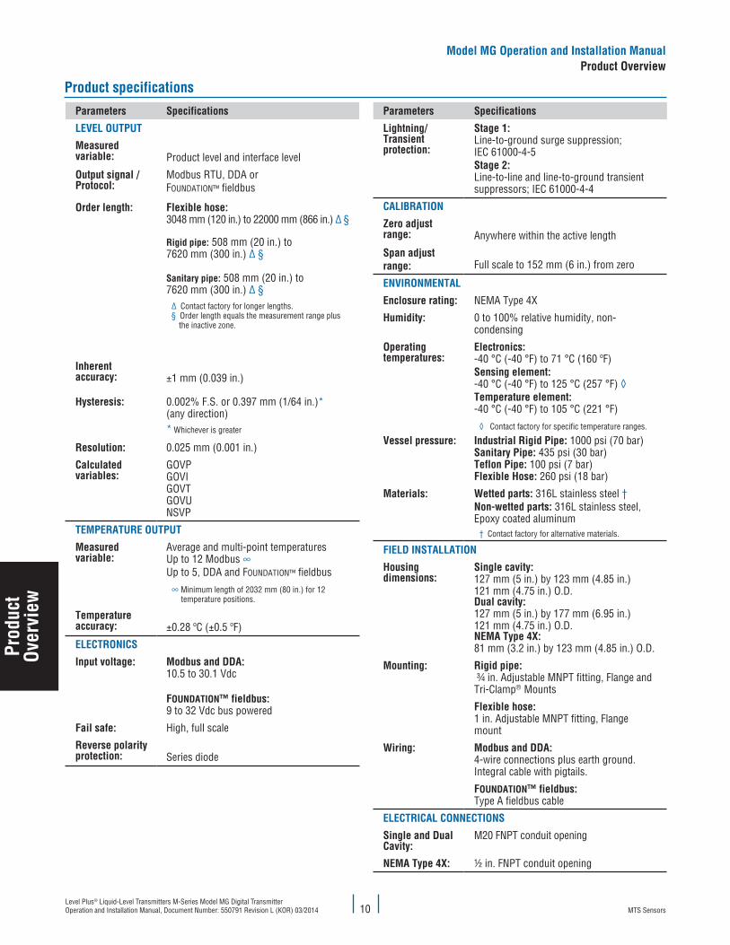
Parameters Specifications
LEVEL OUTPUT
Measured variable: Product level and interface level
Output signal /Protocol:
Modbus RTU, DDA or FOUNDATION™ fieldbus
Order length: Flexible hose:3048 mm (120 in.) to 22000 mm (866 in.) ∆ §
Rigid pipe: 508 mm (20 in.) to 7620 mm (300 in.) ∆ §
Sanitary pipe: 508 mm (20 in.) to 7620 mm (300 in.) ∆ §
∆ Contact factory for longer lengths.§ Order length equals the measurement range plus
the inactive zone.
Inherent accuracy: ±1 mm (0.039 in.)
Hysteresis: 0.002% F.S. or 0.397 mm (1/64 in.)*(any direction) * Whichever is greater
Resolution: 0.025 mm (0.001 in.)
Calculated variables:
GOVPGOVIGOVTGOVUNSVP
TEMPERATURE OUTPUT
Measured variable:
Average and multi-point temperatures Up to 12 Modbus ∞Up to 5, DDA and FOUNDATION™ fieldbus
∞ Minimum length of 2032 mm (80 in.) for 12 temperature positions.
Temperature accuracy: ±0.28 ºC (±0.5 ºF)
ELECTRONICS
Input voltage: Modbus and DDA:10.5 to 30.1 Vdc
FOUNDATION™ fieldbus: 9 to 32 Vdc bus powered
Fail safe: High, full scale
Reverse polarity protection: Series diode
Parameters Specifications
Lightning/Transient protection:
Stage 1: Line-to-ground surge suppression; IEC 61000-4-5Stage 2: Line-to-line and line-to-ground transient suppressors; IEC 61000-4-4
CALIBRATION
Zero adjust range: Anywhere within the active length
Span adjust range: Full scale to 152 mm (6 in.) from zero
ENVIRONMENTAL
Enclosure rating: NEMA Type 4X
Humidity: 0 to 100% relative humidity, non-condensing
Operating temperatures:
Electronics: -40 °C (-40 °F) to 71 °C (160 ºF) Sensing element: -40 °C (-40 °F) to 125 °C (257 °F) ◊Temperature element: -40 °C (-40 °F) to 105 °C (221 °F)
◊ Contact factory for specific temperature ranges.
Vessel pressure: Industrial Rigid Pipe: 1000 psi (70 bar)Sanitary Pipe: 435 psi (30 bar)Teflon Pipe: 100 psi (7 bar) Flexible Hose: 260 psi (18 bar)
Materials: Wetted parts: 316L stainless steel †Non-wetted parts: 316L stainless steel, Epoxy coated aluminum
† Contact factory for alternative materials.
FIELD INSTALLATION
Housing dimensions:
Single cavity:127 mm (5 in.) by 123 mm (4.85 in.)121 mm (4.75 in.) O.D.Dual cavity:127 mm (5 in.) by 177 mm (6.95 in.)121 mm (4.75 in.) O.D.NEMA Type 4X:81 mm (3.2 in.) by 123 mm (4.85 in.) O.D.
Mounting: Rigid pipe: ¾ in. Adjustable MNPT fitting, Flange and Tri-Clamp® Mounts
Flexible hose: 1 in. Adjustable MNPT fitting, Flange mount
Wiring: Modbus and DDA:4-wire connections plus earth ground.Integral cable with pigtails.
FOUNDATION™ fieldbus: Type A fieldbus cable
ELECTRICAL CONNECTIONS
Single and Dual Cavity:
M20 FNPT conduit opening
NEMA Type 4X: ½ in. FNPT conduit opening
Product specifications

MTS SensorsLevel Plus® Liquid-Level Transmitters M-Series Model MG Digital Transmitter
Operation and Installation Manual, Document Number: 550791 Revision L (KOR) 03/201411
Installation and mounting
If the installation is going to occur in a hazadous area, completely read the Agency Information section before starting any work. The Agency Information outlines additional regulations that need to be followed in order for the installation to comply with hazardous area regulations.
This section contains information about storing your transmitter (prior to installation) and detailed procedures for installing and mounting your transmitter.
Storage
If storage is required prior to installation, store indoors in a dry environment at ambient temperature range not exceeding -40 °C (-40 °F) to 71 °C (160 °F).
Stilling wells and guide poles
Level Plus transmitters can be mounted in slotted or un-slotted stilling wells but a slotted stilling well is always preferred. Using a un-slotted stilling well will negatively affect performance of any level device as the level in the stilling well will differ from the level in the tank. The Level Plus transmitter can also be installed to one side of the stilling well to also allow for sampling and manual gauging from the same opening as the automatic tank gauging. Contact Technical Support for details.
Level Plus transmitters do not require a stilling well for installation. Our transmitters are installed in numerous tanks without stilling wells with no loss in performance due to our patented flexible waveguide and hose. A stilling well is highly recommended for agitated, turbulent, and/or fast filling tanks.
Installation
The installation procedures below are illustrated using the adjustable NPT fitting for a threaded flange mount. The procedures will have to be slightly adjusted if using a welded flange or sanitary tri-clamp mount.
RIGID PROBE
Tools Required:• Channel lock pliers• Common screwdriver• 5/32 in. Hex key (allen wrench)
Caution:
It is recommended that assembly and mounting of this transmitter should not be performed alone. To ensure proper and safe assembly of the M-Series transmitter, a minimum of two (2) individuals are recommended. Gloves are also recommended. In addition, PPE is required for work areas such as safety shoes, safety glasses, hard hat, and fire resistant clothing.
Perform the following steps to Install the Model MG Digital transmitter:
1. Remove the stop collar and E-ring. With assistance, feed the rigid pipe through the hole of the removed tank flange until the flange is positioned near the top of the transmitter. Insert the threaded portion of the adjustable fitting into the customer supplied flange and tighten (apply pipe thread sealant if required). Be careful not to drop the flange as it can damage the transmitter.
2. Slide the product float onto the rigid pipe. Slide the interface float (optional) onto the rigid pipe. Install stop collar 2 inches from the bottom (see ‘Note’ below). Do not drop the float(s) or allow them to free fall along the rigid pipe as damage may result. Install E-ring.
Note:
The stop collar can be removed or adjusted based on the float selected for the application. Please consult the factory for more information.
3. Slide float(s) back down to the stop collar to prevent them from free falling during installation into the tank. Insert the rigid pipe (with floats) through the tank opening and lower the transmitter/float assembly into the tank until it rests on the bottom. DO NOT DROP OR DAMAGE THE PIPE.4. Secure the flange onto the tank mount.5. Pull the transmitter upward so the end plug is just resting on the floor of the tank. Tighten the adjustable fitting to hold the transmitter
in place.6. Terminate the field wire cables noting proper wire orientation.
Inst
alla
tion
&
Mou
ntin
g
Model MG Operation and Installation ManualInstallation & Mounting

MTS SensorsLevel Plus® Liquid-Level Transmitters M-Series Model MG Digital Transmitter Operation and Installation Manual, Document Number: 550791 Revision L (KOR) 03/2014
Inst
alla
tion
&M
ount
ing
Model MG Operation and Installation ManualInstallation & Mounting
12
FLEXIBLE PROBE
Caution:
When assembling and installing the Model MG transmitter, be careful not to allow the flexible hose to kink or be coiled in less than 16 in. (406.5 mm) diameter. It is recommended that assembly and mounting of this transmitter should not be done alone. To ensure proper and safe assembly of the Model MG transmitter, a minimum of two (2) individuals are recommended. Gloves are also recommended. PPE is required for work areas such as safe-ty shoes, safety glasses, hard hat, and fire resistant clothing.
Tools Required:
• 9/16 in. Socket and ratchet• Channel lock pliers• 3/16 in. Hex key (allen wrench)
1. Remove the stop collar. With assistance, feed the flexible hose through the hole of the removed tank flange until the flange is positioned at the rigid section of pipe near the top of the transmitter. Insert the threaded portion of the adjustable fitting into the customer supplied flange and tighten (apply pipe thread sealant if required). Be careful not to drop flange on the flexible hose as damage may result. 2. Slide the product float onto the flexible pipe. Slide the interface float (optional) onto the flexible pipe. Install stop collar 3 inches from
the bottom of rigid section (see ‘Note’ below). Do not drop float(s) or allow them to free fall along the flexible pipe as damage may result.
Note:
The stop collar can be removed or adjusted based on the float selected for the application. Please consult the factory for more information.
3. Mount the hook, weight, or the magnet to the welded end-plug section of the pipe (this is the bottom rigid section of the pipe) using the supplied nut, spacer and washer, tighten securely as shown in Figure 5. For the magnet, remove washer before installing in tank.
Weight
Flexible pipe
Magnet
Transmitter retentionusing weight
Bottom-fixing hook(mates with customer supplied
hardware mounted in the tank bottom)Nut
Weldedend-plug
WasherSpacer
Flexible pipe
Weldedend-plug
NutWasherSpacer
Flexible pipe
Weldedend-plug
Transmitter retentionusing magnet
Transmitter retention usingbottom-xing hook
Removewasher
Figure 5. Bottom fixing hardware
DO NOT DROP OR DAMAGE THE PIPE
Important: Avoid kinking or bending the flexible pipe in less than 16 inch (406 mm) diameter or damage may result.
4. Slide float(s) back down to the stop collar to prevent them from free falling during installation into the tank. Insert the flex pipe and floats through the tank riser pipe and lower the transmitter/float assembly into the tank until it rests on the bottom. If you are using a bottom-fixing hook, fasten the hook to the appropriate customer-supplied mating hardware at the tank bottom. 5. Secure the flange onto the tank riser pipe.6. Pull the transmitter upward to straighten the flexible pipe until the resistance of the weight, magnet, or hook is felt without raising the
weight or magnet off the floor of the tank. Tighten the adjustable fitting to hold the transmitter in place. 7. Terminate the field wire cables noting proper wire orientation.

MTS SensorsLevel Plus® Liquid-Level Transmitters M-Series Model MG Digital Transmitter
Operation and Installation Manual, Document Number: 550791 Revision L (KOR) 03/201413
Mounting
The method of mounting the Level Plus M-Series transmitter is dependent on the vessel or tank in which it is being used, and what type of transmitter is being mounted. There are three typical methods for mounting; threaded flange mounting, welded flange mounting, and sanitary tri-clamp mounting.
THREADED FLANGE MOUNTINGIn most applications, the Model MG transmitter can be mounted directly to the tank or flange via a NPT threaded fitting, assuming there is a proper threaded connection available. If the float will not fit through the flange opening when the flange is removed, there must be some alternative means to mount the float on the transmitter from inside the vessel; this may require an access port nearby the entry point of the transmitter as shown in Figure 6.
Riser
NPT fitting
Tank flange(customer suppliedor ordered separately)
Float accessport
Tip of transmitter
Figure 6. Threaded flange mounting for rigid (shown) and flexible pipe
WELDED FLANGE MOUNTINGThe Model MG transmitter can also be mounted to a tank flange as shown in Figure 7. First, install float(s) onto the transmitter. Second, install the float retaining hardware on the tip of the transmitter. To complete the installation, mount the transmitter, flange and float(s) as a unit in to the tank.
Welded flange
Tank flange
Welding sleeve28.6 mm
(1.13 in.) dia
Product float
Riser
Stainless-steelflexible pipe
Interface float
Bottom-fixing weight,magnet or hook
Figure 7. Welded flange mounting for rigid and flexible (shown) pipe
Inst
alla
tion
&
Mou
ntin
g
Model MG Operation and Installation ManualInstallation & Mounting

MTS SensorsLevel Plus® Liquid-Level Transmitters M-Series Model MG Digital Transmitter Operation and Installation Manual, Document Number: 550791 Revision L (KOR) 03/2014
Inst
alla
tion
&M
ount
ing
Model MG Operation and Installation ManualInstallation & Mounting
14
SANITARY TRI-CLAMP MOUNTING
In sanitary applications, the M-Series transmitter is mounted to the tank using a standard sanitary connection and clamp as shown in Figure 8. In most cases it is not necessary to remove the float as the sanitary end-plug fitting is sized to allow installation with the float in place. Please note that some sanitary end-plug styles have float(s) permanently mounted as shown in Figure 8. To install the clamp, the transmitter and float(s) into the mating process connection and attach the sanitary tri-clamp.
Mating process connection(Customer supplied)Top
view
Cable(Customer supplied)
123 mm(4.85 in.)
Riser
Sanitary float(Permanently mounted on some transmitter pipe styles)
81 mm(3.19 in.)152 mm
(6.0 in.)
Tip of transmitter
Sanitary clamp(Customer supplied) Sanitary cap (welded to transmitter pipe)
Figure 8. M-Series Model MG transmitter. Tank mounted with sanitary connection
CPClean-in-place
DPDrain-in-place
with end plug*
TBSanitary*
Inactive zone:81 mm (3.2 in.)from tip (typical)
*This end plug style has permanently mounted floats. Floats cannot be removed from pipe.
DNDrain-in-place
no through hole
Inactive zone:74 mm (2.9 in.)from tip (typical)
Inactive zone:74 mm (2.9 in.)from tip (typical)
Inactive zone:81 mm (3.2 in.)from tip (typical)
Figure 9. End-plug options for transmitters in a sanitary pipe application

MTS SensorsLevel Plus® Liquid-Level Transmitters M-Series Model MG Digital Transmitter
Operation and Installation Manual, Document Number: 550791 Revision L (KOR) 03/201415
Electrical connections and wiring procedures
A typical intrinsically safe connection for the Level Plus M-Series transmitter includes protective safety barriers, a power supply and a reading or monitoring device. Refer to Agency information and Brief Operation Manual for Safe Use for detailed information.
A typical explosion proof connection for the M-Series transmitter includes a power supply and a reading or monitoring device connected using explosion proof conduit. Refer to Agency information and Brief Operation Manual for Safe Use for detailed information.
Notes:
For explosion proof installation, safety barriers are not required and wiring shall be installed in accordance with the National Electric Code ANSI/NFPA 70, Article 501-30 or the regional equivalent.
Safety recommendations for installation
Always follow applicable local and national electrical codes and observe polarity when making electrical connections. Never make electrical connections to the M-Series transmitter with power turned on. Make sure that no wire strands are loose or sticking out of the terminal block connection which could short and cause a problem. Make sure that no wire strands, including shield, are in contact with the electronic module enclosure. The electronics module enclosure is grounded through internal circuitry and electrically isolated from the flameproof enclosure.
Industrial topologies
There are four topologies described and illustrated below. However, the daisy chain topology is not recommended by MTS.
POINT-TO-POINT
The point-to-point topology consists of having only one device on the loop as shown in Figure 10. This topology is not usually used with a bus network since it does not take advantage of placing multiple devices on a loop.
BUS WITH SPURS
The bus with spurs topology has a main trunk cable that has each device connected via its own spur at a junction box as shown in Figure 11. The bus with spurs and tree topologies can also be used together to form a hybrid topology.
TREE ALIGNMENT
The tree topology is very similar to the bus with spurs topology with the main difference of having a common junction box for all of the transmitters as shown in Figure 12. Bus with spurs and tree topologies can also be used together to form a hybrid topology.
DAISY CHAIN
The daisy-chain topology utilizes a single cable that is connected to all of the transmitters with the cable being interconnected at each field device. When using this topology make sure that the wiring practice allows for one transmitter to be disconnected without disconnecting the entire loop as shown in Figure 13. MTS does not suggest using the daisy-chain topology.
Figure 10. Point-to-point topology
Figure 11. Bus with spurs topology
Figure 12. Tree topology
Figure 13. Daisy-chain topology
PLC
PLC
PLC
PLC
Model MG Operation and Installation ManualInstallation & Mounting
Inst
alla
tion
&
Mou
ntin
g

MTS SensorsLevel Plus® Liquid-Level Transmitters M-Series Model MG Digital Transmitter Operation and Installation Manual, Document Number: 550791 Revision L (KOR) 03/2014 16
Recommended cable types
Listed below are general requirements of cable types for the Level Plus Model MG digital transmitter.
CABLE RECOMMENDATION FOR MODBUS AND DDA
Cable recommendation:
• Shielded, twisted pair, 24 AWG or heavier • Minimum 85 °C temperature rating.• Minimum 0.010 in. (0.25 mm) insulation thickness• 30 picofarads/foot or less. (see Notes).
Notes:
1. The return conductor for the power supply circuit is connected to the shield at the safety barrier ground terminal. When determining the capacitance of cable for the power supply circuit, use the manufacturer’s capacitance specifications shown for one conductor and the other conductor connected to the shield. 2. Most cable manufacturers do not list inductance properties for cables. Where the inductance properties are unavailable, ISA RP12.6 (Installation of Intrinsically Safe Instrument Systems in Class I Hazardous Locations) recommends the use of 0.2 µH (micro henries) per foot as a value for cable inductance. 3. Termination and biasing of RS-485 data lines are as follows:
• Biasing - Each M-Series transmitter has internal high impedance biasing resistors (30K Ω) on both RS-485 data lines. No additional biasing resistors should be present on the connecting devices (PLC, DCS, PC, converter).
• Termination - Each M-Series transmitter has an internal termination resistor (100K Ω) installed across the RS-485 signal lines. No additional termination resistors are necessary in the connecting devices (PLC, DCS, PC, converter).
CABLE RECOMMENDATION FOR FOUNDATION™ FIELDBUSGeneral requirements of cable types for the M-Series FOUNDATION™ fieldbus transmitter:
Type A, FOUNDATION™ fieldbus cable (see Table 1 to the right)
Parameter Value
Resistance 15Ω/km to 150 Ω/km
Inductance 0.4mH/kn to 1mH/km
Capacitance 80nF/km to 200nF/km
Table 1. Type A cableElectrical conduit installation
Important:
Seal all conduits within 18 in. (457 mm).
Notes:1. Use a flameproof type conduit sealing fitting.2. Tighten housing cover (both front and back covers if dual cavity) to full stop against the O-ring. Make sure O-ring(s) are present and clean.3. Do not over-tighten compression fittings.4. Use side conduit entry only.5. In high humidity areas, use a breather drain type conduit sealing fitting to minimize moisture intrusion.
Flameproof typeconduit sealing fittingwithin 457 mm (18 in.)of housing
NPT FittingDo not over-tightencompression fitting!
Interface float(ordered
separately)
Product float(ordered
separately)
View shown withcover removed
Plugged entryDo not use(see notes)
3/4 NPT conduit accessUse NPT conduit fitting only!
Conduit(flexible or rigid)
Conduit fromcontrol room
Do not remove cover with circuit live in harzardous locations!
Follow safe work procedures.
Model MG Operation and Installation ManualElectrical Connections and Wiring
Conn
ectio
ns &
Wiri
ng

MTS SensorsLevel Plus® Liquid-Level Transmitters M-Series Model MG Digital Transmitter
Operation and Installation Manual, Document Number: 550791 Revision L (KOR) 03/201417
Grounding
Note:
Grounding the transmitter through a threaded conduit connection does not provide sufficient ground.
There are two methods to provide an earth ground to the earth ground of the electronics. • Run an earth ground through the conduit and connect directly to the earth ground of the electronics• Run an earth ground directly to the ground lug on the outside of the housing and connect the ground lug inside of the housing to the earth
ground of the electronics. Refer to Table 2 and Table 3 below for a limited listing of possible barrier selections.
Model MG Operation and Installation ManualElectrical Connections and Wiring
Conn
ectio
ns &
Wiri
ng

MTS SensorsLevel Plus® Liquid-Level Transmitters M-Series Model MG Digital Transmitter Operation and Installation Manual, Document Number: 550791 Revision L (KOR) 03/2014 18
Maintenance and field service
This section contains information about post installation maintenance and provides an overview of MTS Sensors’ repair and replacement procedures.
General maintenance and field service requirements
Notes:
Please contact Technical Support or Customer Service for help when damage occurs in order to obtain a return materials authorization (RMA) number. Packages without a RMA number may be rejected. Any unit that was used in a process must be properly cleaned in accordance with OSHA standards, before it is returned to the factory. A Material Safety Data Sheet (MSDS) must accompany material that was used in any media.
FLOAT MAINTENANCE
Level Plus M-Series transmitters use magnetostrictive technology and only have one moving part—the float. This technology ensures no scheduled maintenance or recalibration is required. However, MTS recommends that you check the transmitter pipe annually for build up of process material. Floats should move freely along the pipe. If they do not, routine cleaning should be performed.
FIELD SERVICE
If damage does occur to a M-Series transmitter, the transmitter can be serviced in the field with replacement parts. All electronic parts can be changed in the field without having to open the process vessel. Please contact Technical Support and refer to the Transmitter Electronics Replacement Guide (MTS part no. 551104) for detailed steps of field replacement.
SERVICE / RMA POLICY
If the customer suspects their transmitter is damaged or not functioning correctly, call MTS Technical Support for further instruction. If it is necessary to return the transmitter to the factory, an RMA number is required and can only be issued by Technical Support. Product returns that do not include an RMA will be returned to the customer. MTS evaluates the transmitter and advises the customer whether a repair or replacement is necessary and any cost that might be incurred. If the customer declines repair/replacement or the transmitter has no fault found, the unit is sent back as is and the customer is charged with a standard evaluation fee.
If the transmitter is under warranty and a manufacturer’s defect is detected, there will be no cost to the customer for repair or replacement. If the transmitter is out of warranty or if the customer has damaged the transmitter, a repair or replacement quote will be provided. In specific cases where the transmitter can not be removed and returned to the factory for evaluation, field evaluations can be performed on-site by an MTS technician. If field evaluation must be performed, the customer is responsible for all expenses incurred for travel, evaluation, parts and repair time. However, if the transmitter is under warranty and the problem is due to a manufacturer’s defect, there is no cost to the customer for replacement parts. To discuss all service options, contact Technical Support.
Model MG Operation and Installation ManualMaintenance and Field Service
Mai
nten
ance
&
Fiel
d Se
rvic
e

MTS SensorsLevel Plus® Liquid-Level Transmitters M-Series Model MG Digital Transmitter
Operation and Installation Manual, Document Number: 550791 Revision L (KOR) 03/201419
Troubleshooting
Table 4 below contains troubleshooting information for the Model MG digital transmitter.
Troubleshooting procedures
Symptom Possible Cause Action
No communication with transmitter No power Check voltage at transmitter
Wiring incorrect Reference installation drawing (see’Electrical connections and wiring’)
Wrong address DDA factory default is ‘192 ’Modbus factory default is ‘247 ’
Wrong software Confirm correct software
Wrong protocol Confirm software and transmitter are same protocol
Missing magnet error Float not recognized Confirm that the float is attached
Float is in the dead zone Raise float to see if the error stops
Wrong number of floats selected Confirm that the number of floats on the transmitter and the number of floats the transmitter is attempting to verify are the same.
Trigger level error Gain needs to be adjusted Consult Factory
SE is damaged Consult Factory
Min. trigger level too high Consult Factory
Volume calculation error No strap table entered Enter strap table
Level outside range of strap table Enter additional points in strap table
Strap table incorrect Check value entries
VCF error No VCF table entered Enter VCF table
VCF table incorrect Check VCF value entries
Table 4. Troubleshooting reference
Model MG Operation and Installation ManualTroubleshooting Procedures
Trou
bles
hoot
ing
Proc
edur
es

MTS SensorsLevel Plus® Liquid-Level Transmitters M-Series Model MG Digital Transmitter Operation and Installation Manual, Document Number: 550791 Revision L (KOR) 03/2014 20
Quick start-up guide (Modbus and DDA)
BEFORE YOU BEGINNote:
You must use a RS-485 converter with “Send Data Control” and the M-Series Set-up Software to ensure proper operation. Example: B & B Electronics 485BAT3 (815-433-5100 www.bb-elec.com).
Default communication parameters
Modbus: 4800 BAUD 8, N, 1
DDA: 4800 BAUD 8, E, 1
QUICK START-UP PROCEDURE
1. Connect +24 Vdc to terminals.2. Connect data lines to terminals.3. Connect the PC (or other device) to data lines.
(If you are using a PC, use a RS-232 to RS-485 converter. See Note above for more information.) 4. Turn on power to the transmitter.5. Start the M-Series Setup Software. Click the ‘Data From Device’ tab. Click the ‘Device’ pull down menu (located in the upper right
corner of the window) to verify communications using factory default address ‘247 ’ for Modbus or factory default ‘192 ’ for DDA. 6. Change the address to one that is suitable for the installation network. 7. Verify proper operation of product and or interface floats and temperature. 8. Turn off power to the transmitter. 9. Remove data lines. 10. Install the transmitter into the vessel (see Installation and mounting on page 11). 11. Reconnect power and data lines. 12. Verify communications with the host system (repeat step 5). 13. Calibrate current tank level (optional). Setup is complete.
Model MG Operation and Installation ManualQuick Start-Up Guide - Modbus/DDA User Interface
Quic
k St
art-u
pM
odbu
s/DD
A In
terfa
ce

MTS SensorsLevel Plus® Liquid-Level Transmitters M-Series Model MG Digital Transmitter
Operation and Installation Manual, Document Number: 550791 Revision L (KOR) 03/201421
Modbus Interface
Notes:
Termination and biasing of RS-485 data lines are as follows: • Biasing Each M-Series transmitter has internal high impedance biasing resistors (30K Ω) on both RS-485 data lines. No additional biasing resistors should be present on the connecting devices (PLC, DCS, PC, Converter).• Termination Each M-Series transmitter has an internal termination resistor (100K Ω) installed across the RS-485 signal lines. No additional termination resistors are necessary in the connecting devices (PLC, DCS, PC, Converter).
MODBUS IMPLEMENTATION
The Modbus implementation for the M-Series digital transmitter conforms to the ‘Modicon Modbus Protocol Reference Guide, PIMBUS-300 Rev. G’ available from Modicon, Inc. The information provided below assumes familiarity with the Modbus protocol as outlined in this reference guide. All information provided applies to Modbus RTU protocol only.
MODBUS FUNCTION CODES
Communication parameters:
Modbus: 4800 BAUD or 9600 8, N, 1(Reference) Monitor: Modbus RTU Variable BAUD Rate 8, E, 1
The following Modbus function codes are supported:Function 03 - Read Holding RegistersFunction 04 - Read Input RegistersFunction 06 - Preset Single RegisterFunction 08 - Diagnostics (Subfunction 00, Return Query Data)Function 08 - Diagnostics (Subfunction 01, Restart Communications Option)Function 08 - Diagnostics (Subfunction 04, Force Listen Only Mode)Function 16 - Preset Multiple RegistersFunction 17 - Report Slave ID
Function 03 - Read Holding Registers
The device responds to this message by returning the contents of the requested data register(s). (See ‘Device Modbus Register Maps’ on page 22).
The following implementation-specific considerations apply:
• If an unsupported or reserved register is requested, a maximum negative value (8000H or 80000000H for paired registers) is returned (See ‘Device Modbus Register Maps’ on page 212 for unsupported/reserved registers).• If a register contains an device error a maximum negative value
is returned.• If a register is blank, indicating that the desired function is not
enabled (e.g., volume calculations) a value of 0000H is returned. • Unsupported or reserved bits will always be set to 0. See ‘Device Modbus Register Maps’ on page 22 for alarm bit definitions.
Function 04 - Read Input Registers
This function is handled exactly the same as Function 03. (Be advised that all registers are read-only in this implementation).
Function 06 – Preset Single Registers
Confirmation of successful transmission is confirmed when the device responds by echoing back what was sent.
Function 08 - Diagnostics (Subfunction 00, Return Query Data)
The device responds to this request with the following data:Slave address: echoedFunction: 08HSubfunction high: 00HSubfunction low: 00HQuery data (16-bit): echoedError check: 16-bit CRC/8-bit LRC
Function 08 - Diagnostics (Subfunction 01, Restart Communications Option)
Note:
The communications event log is not supported. The “Query data” field is irrelevant (normally, FF00H would clear the log).
If the device is in listen-only mode, the device responds to this message by switching out of listen-only mode - (resulting in no response being sent to the request).
If the device is not in listen only mode, it responds as follows:Slave address: echoedFunction: 08HSubfunction high: 00HSubfunction low: 01HQuery data (16-bit): echoed (0000H or FF00H)Error check: 16-bit CRC/8-bit LRC
Function 08 - Diagnostics (Subfunction 04, Force Listen-Only Mode)
The device responds to this request by switching to listen-only mode. Messages are still received and parsed, but no responses are transmitted. To switch out of listen-only mode, issue a ‘Restart Communications Option’ request (function 08, subfunction 01) or cycle power.Function 16 - Preset Multiple Registers
The device response returns the slave address, function code, start-ing address, and quantity of registers preset.
Model MG Operation and Installation ManualModbus User Interface
Mod
bus
User
Inte
rface

MTS SensorsLevel Plus® Liquid-Level Transmitters M-Series Model MG Digital Transmitter Operation and Installation Manual, Document Number: 550791 Revision L (KOR) 03/2014
Mod
bus
User
Inte
rface
Model MG Operation and Installation ManualModbus User Interface
22
MODBUS FUNCTION CODES (CONTINUED)
Function 17 - Report Slave ID
The device responds to this request with the following data:Slave address: echoedFunction: 11HByte count: 05HSlave ID: FFHRun indicator status: FFH (ON)Additional data: ‘DMS’Error check: 16-bit CRC/8-bit LRC
Modbus ExceptionsThe following standard Modbus exceptions are implemented:Error code 01 (Illegal Function)
Reported when:
• A function other than 03, 04, 06, 08, 16 or 17 is requested• Function 08 is requested, and a subfunction other than 00, 01,
or 04 is requestedError code 02 (Illegal Data Address)
Reported when:
• Function 03 or 04 is requested and the starting register number is greater than 5198 (register greater than 35198 or 45198)
Error code 03 (Illegal Data Value)
Reported when: • Function 03 or 04 is requested and the number of data points
is greater than 800.
DEVICE MODBUS REGISTER MAPS
Modbus Register
Data Address
Data Description ‡ denotes duplicate register
Note Reference
30001 0000 Product Level High Word (x 1000)
2, Page 263, Page 27
30002 0001 Product Level Low Word (x 1000)
30003 0002 Interface Level High Word (x 1000)
30004 0003 Interface Level Low Word (x 1000)
30005 0004 Roof Level High Word (x 1000)
Inactive
30006 0005 Roof Level Low Word (x 1000)
Inactive
30007 0006 Temperature 1 High Word (x 10000)
4, Page 27
30008 0007 Temperature 1 Low Word (x 10000)
30009 0008 Temperature 2 High Word (x 10000)
30010 0009 Temperature 2 Low Word (x 10000)
30011 0010 Temperature 3 High Word (x 10000)
30012 0011 Temperature 3 Low Word (x 10000)
30013 0012 Temperature 4 High Word (x 10000)
30014 0013 Temperature 4 Low Word (x 10000)
30015 0014 Temperature 5 High Word (x 10000)
30016 0015 Temperature 5 Low Word (x 10000)
30017 0016 Temperature Average High Word (x 10000)
5, Page 27
Modbus Register
Data Address
Data Description ‡ denotes duplicate register
Note Reference
30018 0017 Temperature Average Low Word (x 10000)
30019 0018 GOVP High Word 6, Page 2730020 0019 GOVP Low Word30021 0020 GOVI High Word 7, Page 2730022 0021 GOVI Low Word30023 0022 GOVT High Word 8, Page 2730024 0023 GOVT Low Word30025 0024 GOVU High Word 9, Page 2730026 0025 GOVU Low Word30027 0026 NSVP High Word 10, Page 2730028 0027 NSVP Low Word30029 0028 MASS High Word30030 0029 MASS Low Word30031 0030 Temperature
Correction Method High Word
11, Page 27
30032 0031 Temperature Correction Method Low Word
30033 0032 API Gravity High Word (x 100)
30034 0033 API Gravity Low Word (x 100)
30035 0034 Working Capacity High Word (x 10)
30036 0035 Working Capacity Low Word (x 10)
30037 0036 TEC High Word (x 10000000)
12, Page 27
30038 0037 TEC Low Word (x 10000000)

MTS SensorsLevel Plus® Liquid-Level Transmitters M-Series Model MG Digital Transmitter
Operation and Installation Manual, Document Number: 550791 Revision L (KOR) 03/201423
Modbus Register
Data Address
Data Description ‡ denotes duplicate register
Note Reference
30039 0038 Density High Word (x 100)
13, Page 27
30040 0039 Density Low Word (x 100)
30041 0040 Reference Tempera-ture High Word (x 10)
14, Page 27
30042 0041 Reference Tempera-ture Low Word (x 10)
30043 0042 Volume Calculation Mode High Word
15, Page 27
30044 0043 Volume Calculation Mode Low Word
30045 0044 Sphere Radius High Word (x 10)
16, Page 27
30046 0045 Sphere Radius Low Word (x 10)
30047 0046 Sphere Offset High Word (x 10)
17, Page 27
30048 0047 Sphere Offset Low Word (x 10)
30049 0048 Average Interval High Word
18, Page 27
30050 0049 Average Interval Low Word
30051 0050 Alarm/Status High Word
19, Page 27
30052 0051 Alarm/Status Low Word
30053 0052 VCF Calculation Error Status
20, page 29
30054 0053 Volume Calculation Error Status
21, page 29
30055 - 30099
0054 - 0098
Reserved 22, page 29
30100 0099 Temperature Units High
23, page 29
30101 0100 Temperature Units Low
30102 0101 Density Units High 24, page 2930103 0102 Density Units Low30104 0103 Volume Units High 25, page 2930105 0104 Volume Units Low30106 0105 Length Units High 26, page 2930107 0106 Length Units Low30108 0107 Mass Units High 27, page 2930109 0108 Mass Units Low30110 0109 Set New Device
Address28, page 29
30200 199 Product Level High Word (x1000) ‡
2, Page 263, Page 27
30201 200 Product Level Low Word (x1000) ‡
Modbus Register
Data Address
Data Description ‡ denotes duplicate register
Note Reference
30202 201 Interface Level High Word (x1000) ‡
30203 202 Interface Level Low Word (x1000) ‡
30204 203 Roof Level High Word (x1000) ‡
Inactive
30205 204 Roof Level Low Word (x1000) ‡
Inactive
30206 205 Temperature 1 High Word (x10000)
4, Page 27
30207 206 Temperature 1 Low Word (x10000)
30208 207 Temperature 2 High Word (x10000)
30209 208 Temperature 2 Low Word (x10000)
30210 209 Temperature 3 High Word (x10000)
30211 210 Temperature 3 Low Word (x10000)
30212 211 Temperature 4 High Word (x10000)
30213 212 Temperature 4 Low Word (x10000)
30214 213 Temperature 5 High Word (x10000)
30215 214 Temperature 5 Low Word (x10000)
30216 215 Temperature 6 High Word (x10000)
30217 216 Temperature 6 Low Word (x10000)
30218 217 Temperature 7 High Word (x10000)
30219 218 Temperature 7 Low Word (x10000)
30220 219 Temperature 8 High Word (x10000)
30221 220 Temperature 8 Low Word (x10000)
30222 221 Temperature 9 High Word (x10000)
30223 222 Temperature 9 Low Word (x10000)
30224 223 Temperature 10 High Word (x10000)
30225 224 Temperature 10 Low Word (x10000)
30226 225 Temperature 11 High Word (x10000)
30227 226 Temperature 11 Low Word (x10000)
30228 227 Temperature 12 High Word (x10000)
30229 228 Temperature 12 Low Word (x10000)
DEVICE MODBUS REGISTER MAPS (CONTINUED)
Model MG Operation and Installation ManualModbus User Interface
Mod
bus
User
Inte
rface

MTS SensorsLevel Plus® Liquid-Level Transmitters M-Series Model MG Digital Transmitter Operation and Installation Manual, Document Number: 550791 Revision L (KOR) 03/2014
Mod
bus
User
Inte
rface
Model MG Operation and Installation ManualModbus User Interface
24
Modbus Register
Data Address
Data Description ‡ denotes duplicate register
Note Reference
30230 229 Temperature Average High Word (x10000)
5, Page 27
30231 230 Temperature Average Low Word (x10000)
30232 231 GOVP High Word ‡ 6, Page 2730233 232 GOVP Low Word ‡30234 233 GOVI High Word ‡ 7, Page 2730235 234 GOVI Low Word ‡30236 235 GOVT High Word ‡ 8, Page 2730237 236 GOVT Low Word ‡30238 237 GOVU High Word ‡ 9, Page 2730239 238 GOVU Low Word ‡30240 239 NSVP High Word ‡ 10, Page 2730241 240 NSVP Low Word ‡30242 241 MASS High Word ‡30243 242 MASS Low Word ‡30244 243 Temperature
Correction Method High Word ‡
11, Page 27
30245 244 Temperature Correction Method Low Word ‡
30246 245 API Gravity High Word (x100) ‡
30247 246 API Gravity Low Word (x100) ‡
30248 247 Working Capacity High Word (x10) ‡
30249 248 Working Capacity Low Word (x10) ‡
30250 249 TEC High Word (x10000000) ‡
12, Page 27
30251 250 TEC Low Word (x10000000) ‡
30252 251 Density High Word (x100) ‡
13, Page 27
30253 252 Density Low Word (x100) ‡
30254 253 Reference Temperature High Word (x10) ‡
14, Page 27
30255 254 Reference Temperature Low Word (x10) ‡
30256 255 Volume Calculation Mode High Word ‡
15, Page 27
30257 256 Volume Calculation Mode Low Word ‡
30258 257 Sphere Radius High Word (x10) ‡
16, Page 27
Modbus Register
Data Address
Data Description ‡ denotes duplicate register
Note Reference
30259 258 Sphere Radius Low Word (x10) ‡
30260 259 Sphere Offset High Word (x10) ‡
17, Page 27
30261 260 Sphere Offset Low Word (x10) ‡
30262 261 Average Interval High Word ‡
18, Page 27
30263 262 Average Interval Low Word ‡
30264 263 Alarm/Status High Word ‡
19, Page 27
30265 264 Alarm/Status Low Word ‡
30266 265 VCF Calculation Error Status ‡
20, page 28
30267 266 Volume Calculation Error Status ‡
21, page 28
30300 299 Temperature Units High ‡
23, page 28
30301 300 Temperature Units Low ‡
30302 301 Density Units High ‡ 24, page 28
30303 302 Density Units Low ‡
30304 303 Volume Units High ‡ 25, page 28
30305 304 Volume Units Low ‡
30306 305 Length Units High ‡ 26, page 28
30307 306 Length Units Low ‡
30308 307 Mass Units High ‡ 27, Page 27
30309 308 Mass Units Low ‡
30310 309 Set New Device Address ‡
28, page 28
31101 1100 Tank offset High (x 10)
29, page 28
31102 1101 Tank Offset Low (x 10)
31103 1102 Calibrate Using Current Product Level High (x 1000)
30, page 28
31104 1103 Calibrate Using Current Product Level Low (x 1000)
31105 1104 Calibrate Using Current Interface Level High (x 1000)
31, page 28
DEVICE MODBUS REGISTER MAPS (CONTINUED)

MTS SensorsLevel Plus® Liquid-Level Transmitters M-Series Model MG Digital Transmitter
Operation and Installation Manual, Document Number: 550791 Revision L (KOR) 03/201425
DEVICE MODBUS REGISTER MAPS (CONTINUED)
Modbus Register
Data Address
Data Description ‡ denotes duplicate register
Note Reference
31106 1105 Calibrate Using Current Interface Level Low (x 1000)
31107 1106 Calibrate Using Current Roof Level High (x 1000)
32, Page 29
31108 1107 Calibrate Using Current Roof Level Low (x 1000)
31109 1108 Alarm Units High 33, Page 2931110 1109 Alarm Units Low31111 1110 Interface High Alarm
High (x 100)34, Page 29
31112 1111 Interface High Alarm Low (x 100)
31113 1112 Interface Low Alarm High (x 100)
35, Page 29
31114 1113 Interface Low Alarm Low (x 100)
31115 1114 Product High Alarm High (x 100)
36, Page 29
31116 1115 Product High Alarm Low (x 100)
31117 1116 Product Low Alarm High (x 100)
37, Page 29
31118 1117 Product Low Alarm Low (x 100)
31119 1118 Roof High Alarm High (x 100)
38, Page 29
31120 1119 Roof High Alarm Low (x 100)
31121 1120 Roof Low Alarm High (x 100)
39, Page 29
31122 1121 Roof Low Alarm Low (x 100)
31123 1122 Temperature Average High Alarm High (x 100)
40, Page 29
31124 1123 Temperature Average High Alarm Low (x 100)
31125 1124 Temperature Average Low Alarm High (x 100)
41, Page 29
31126 1125 Temperature Average Low Alarm Low (x 100)
31127– 31998
1126 – 1997
Reserved 22, page 28
31999 1998 Number Of Strap Table Entries High
42, Page 29
32000 1999 Number Of Strap Table Entries Low
32001 2000 Strap Table Level 1 High (x 10000)
43, Page 29
Modbus Register
Data Address
Data Description ‡ denotes duplicate register
Note Reference
32002 2001 Strap Table Level 1 Low (x 10000)
32003 2002 Strap Table Level 2 High (x 10000)
32004 2003 Strap Table Level 2 Low (x 10000)
32005 2004 Strap Table Level 3 High (x 10000)
32006 2005 Strap Table Level 3 Low (x 10000)
|| |||| |||| ||
32199 2198 Strap Table Level 100 High (x 10000)
44, Page 29
32200 2199 Strap Table Level 100 Low (x 10000)
32201 2200 Strap Table Volume 1 High
45, Page 29
32202 2201 Strap Table Volume 1 Low
32203 2202 Strap Table Volume 2 High
32204 2203 Strap Table Volume 2 Low
32205 2204 Strap Table Volume 3 High
32206 2205 Strap Table Volume 3 Low
|| |||| |||| ||
32399 2398 Strap Table Volume 100 High (x 10000)
46, Page 29
32400 2399 Strap Table Volume 100 Low (x 10000)
32401 – 34998
2400 – 4997
Reserved
34999 4998 Number Of VCF Table Entries High
47, Page 29
35000 4999 Number Of VCF Table Entries Low
35001 5000 VCF Table Tempera-ture 1 High (x 10000)
48, Page 29
35002 5001 VCF Table Tempera-ture 1 Low (x 10000)
35003 5002 VCF Table Tempera-ture 2 High (x 10000)
Model MG Operation and Installation ManualModbus User Interface
Mod
bus
User
Inte
rface

MTS SensorsLevel Plus® Liquid-Level Transmitters M-Series Model MG Digital Transmitter Operation and Installation Manual, Document Number: 550791 Revision L (KOR) 03/2014
Mod
bus
User
Inte
rface
Model MG Operation and Installation ManualModbus User Interface
26
DEVICE MODBUS REGISTER MAPS (CONTINUED)
Modbus Register
Data Address
Data Description ‡ denotes duplicate register
Note Reference
35004 5003 VCF Table Tempera-ture 2 Low (x 10000)
35005 5004 VCF Table Tempera-ture 3 High (x 10000)
35006 5005 VCF Table Tempera-ture 3 Low (x 10000)
|| |||| |||| ||
35099 5098 VCF Table Tempera-ture 50 High (x 10000)
49, page 30
35100 5099 VCF Table Tempera-ture 50 Low (x 10000)
35101 5100 VCF Table Correction 1 High (x 10000)
50, page 30
Modbus Register
Data Address
Data Description ‡ denotes duplicate register
Note Reference
35102 5101 VCF Table Correction 1 Low (x 10000)
35103 5102 VCF Table Correction 2 High (x 10000)
35104 5103 VCF Table Correction 2 Low (x 10000)
35105 5104 VCF Table Correction 3 High (x 10000)
35106 5105 VCF Table Correction 3 Low (x 10000)
|| |||| |||| ||
35199 5198 VCF Table Correction 50 High (x 10000)
51, page 30
35200 5199 VCF Table Correction 50 Low (x 10000)
SPECIAL/ADVANCED DIAGNOSTIC REGISTER MAPS
Modbus Register
Data Address
Data Description Note Reference
35201 5200 Num_Lineariztion_ Entries_HiNum_Lineariztion_ Entries_Lo
35203 5202 - 5999
Lintable_Level1_HiLintable_Level1_Lo
35601 5600 Lintable_Level200_HiLintable_Level200_Lo
35603 5602 - 5999
Lintable_Error1_HiLintable_Error1_Lo
Modbus Register
Data Address
Data Description Note Reference
36001 6000 Lintable_Error200_HiLintable_Error200_Lo
36003 6002 - 6399
Lintable_Slope1_HiLintable_Slope1_Lo
36401 6400 Lintable_Slope200_HiLintable_Slope200_Lo
HOW UNITS ARE USED
Registers that are read or preset are done so using the current unit type’s programmed unit.
For example: If the current unit type is ‘Length’ and you currently have selected ‘Feet’ as your unit, then the value returned will be in that unit. Make sure the value programmed is also done so using that unit.
MODBUS REGISTER MAP NOTE REFERENCES
1. All registers can be accessed using either Modbus Function 03 (Read Holding Registers) or Modbus Function 04 (Read Input Registers). However, all registers are read-only in this implementation. For example: Registers 30001 and 30002 (using Function 03) can also be read as registers 40001 and 40002 (using Function 04).
2. Pairs of registers identified as ‘High Word’ and ‘Low Word’ must be read together reading the ‘High Word” first. Both values need to be concatenated by the master to form a 32-bit ‘long word’ quantity.
For example: Register 30001 (16-bit high word) = 0002H (Must be read first) Register 30002 (16-bit low word) = 3F8CH Long word (32-bit) = 00023F8CH (decimal 147340) Or: Register 30001 (high word) = 2 Register 30002 (low word) = 16268 Multiply register 30001 x 65536 : 2 x 65536 = 131072 Add result to register 30002 : 131072 + 16268 = 147340

MTS SensorsLevel Plus® Liquid-Level Transmitters M-Series Model MG Digital Transmitter
Operation and Installation Manual, Document Number: 550791 Revision L (KOR) 03/201427
DEVICE MODBUS REGISTER MAPS (CONTINUED)
3. All registers identified as ‘(x 10)’,’(x 100)’ ,’(x 10000)’ ,’ (x 100000000)’ or ‘(x 1000)’ have been scaled (multiplied) by a factor of 10, 100, 1000, 10000 or 10000000 before transmission to preserve the fractional portion of the data value. The master must divide these values by the scale factor as necessary. For example: Register 30001 (16-bit high word) = 0002H Long word (32-bit) = 00023F8CH (decimal 147340) Divide by 1000, actual value = 147.340
4. Individual digital temperature
5. Average submerged temperature
6. GOVP = Gross Observed Volume Product
7. GOVI = Gross Observed Volume Interface
8. GOVT = Gross Observed Volume Total
9. GOVU = Gross Observed Volume Ullage
10. NSVP = Net Standard Volume of Product
11. Temperature Correction Method There are five methods to choose from: 1 = (6A) Heavy Oils 2 = (6B) Light Oils 3 = (6C) Chemicals 4 = Chemicals with wider coefficients than 6C and a movable reference temperature (6C Mod). 5 = Custom Table.
12. Thermal Expansion Coefficient (TEC) Temperature correction method ‘6C’ uses the thermal expan- sion coefficient of the product being measured to determine the volume correction factor. Allowable values are 270.0 to 930.0. TEC Units are in 10E-6/Deg F.
13. Density Temperature correction method ‘6C’ and ‘Custom Table’ requires you to enter the density (at the given reference temperature) of the product being measured for the net mass calculation.
14. Reference Temperature This is the desired base temperature for the VCF calculation when Temperature Correction Method ‘6C Mod’ is used. 15. Volume Calculation Mode
This is the mode you wish the volume calculations to be performed by: 1 = Use Strap Table 0 = Use Sphere Calculation
16. Sphere Radius The radius of the sphere when volume calculations are performed (using the sphere calculation mode).
17. Sphere Offset The offset of the sphere when volume calculations are performed (using the sphere calculation mode).
18. Average Interval All level, temperature and volume calculation can be averaged using timed method. Allowable values are as follows: 0 = 1 second (default) 5 = 5 seconds 10 = 10 seconds 15 = 15 seconds 20 = 20 seconds 25 = 25 seconds 30 = 30 seconds 35 = 35 seconds 40 = 40 seconds 45 = 45 seconds 50 = 50 seconds 55 = 55 seconds 60 = 60 seconds
19. Alarm/Status bit definitions: D1 Interface Alarm High D2 Interface Alarm Low D3 Product Alarm High D4 Product Alarm Low D5 Roof Alarm High D6 Roof Alarm Low D7 Average Temperature Alarm High D8 Average Temperature Alarm Low D9 Magnet Is Missing D10 Digital Temperature 0 Error D11 Digital Temperature 1 Error D12 Digital Temperature 2 Error D13 Digital Temperature 3 Error D14 Digital Temperature 4 Error D15 Digital Temperature Average Error D16 – D32 Reserved For each corresponding alarm bit: 0 = ALARM OFF 1 = ALARM ON Reserved bits will always be set to 0 (OFF).
Model MG Operation and Installation ManualModbus User Interface
Mod
bus
User
Inte
rface

MTS SensorsLevel Plus® Liquid-Level Transmitters M-Series Model MG Digital Transmitter Operation and Installation Manual, Document Number: 550791 Revision L (KOR) 03/2014
Mod
bus
User
Inte
rface
Model MG Operation and Installation ManualModbus User Interface
28
DEVICE MODBUS REGISTER MAPS (CONTINUED)
20. Volume Correction Factor Calculation Error Status. This value can only be read. If there is no error performing the volume correction factor then the value is zero otherwise, the value is a non-zero code and one of the following: 1 = Invalid API value or invalid temperature input value for 6A or 6B VCF calculation. 2 = Invalid API value or invalid temperature input range for 6A VCF calculation. 3 = Invalid API value or invalid temperature input range for 6B VCF calculation. 4 = Invalid API value or invalid temperature input value for 6C VCF calculation. 5 = Invalid API value or invalid temperature range for 6C VCF calculation. 6 = Invalid API value or invalid temperature range for 6C Wide VCF calculation. 7 = Invalid delta temperature for 6C VCF calculation. 8 = Interpolation error, temperature value not found in the table. 9 = Invalid or No VCF method selected.
21. Volume Calculation Error Status This value can only be read. If there is no error performing the volume calculations then the value is zero otherwise the value Is a non-zero code and one of the following: 1 = Negative table entries are not allowed. 2 = Interpolation error, level value not found in the table. 3 = Sphere Calculation error, level exceeds sphere radius x 2. 4 = Calculated a negative volume value.
22. Undefined or reserved registers within the register map will return a maximum negative value (8000H, or 80000000H for register pairs). Attempting to read registers outside the register map (35198 or higher) will cause a Modbus Exception Error Code 02 (Illegal Data Value) to be returned.
23. Temperature Units The value for temperature units can be one of the following codes: 0 = Celsius 1 = Fahrenheit
24. Density Units High The value for density units can be one of the following codes: 0 = Grams/Milliliters 1 = Grams/Liter 2 = Kilograms/Cubic Meters 3 = Kilograms/Liter 4 = Pounds/Cubic Inch 5 = Pounds/Cubic Foot 6 = Pounds/Gallon 7 = Tonnes/Cubic Meter 8 = Tons/Cubic Yard
25. Volume Units The value for volume units can be one of the following codes: 0 = Liters 1 = Cubic Millimeters 2 = Cubic Meters 3 = Cubic Inches 4 = Cubic Feet 5 = Gallons 6 = Barrels
26. Length Units The value for length units can be one of the following codes: 0 = Millimeters 1 = Centimeters 2 = Meters 3 = Kilometers 4 = Inches 5 = Feet 6 = Yards
27. Mass Units The value for mass units can be one of the following codes: 0 = Kilograms 1 = Grams 2 = Ounces 3 = Pounds 4 = Tons 5 = Tonnes
28. Set New Device Address This register will program the new device address. Valid values for Modbus are between: 1 – 247.
29. Tank Offset This is the value that will be added or subtracted from the level measurements. This allows the tank level reading to be calibrated to the users hand gauged tank reading (or other reference guide). (See notes 30, 31 and 32) for more information.
30. Calibrate Using Current Product Level This is used to calibrate the level measurements. This allows the user to enter the hand gauged tank reading (or other level reference guide) of the Product and the device will calculate the necessary calibration offset. The calculated value will then be stored as the ‘Tank Offset’. (See note 29)
31. Calibrate Using Current Interface Level This is used to calibrate the level measurements. This allows the user to enter the hand gauged tank reading (or other level reference guide) of the Interface and the device will calculate the necessary calibration offset. The calculated value will then be stored as the ‘Tank Offset’. (See note 29)

MTS SensorsLevel Plus® Liquid-Level Transmitters M-Series Model MG Digital Transmitter
Operation and Installation Manual, Document Number: 550791 Revision L (KOR) 03/201429
DEVICE MODBUS REGISTER MAPS (CONTINUED)
32. Calibrate Using Current Roof Level This is used to calibrate the level measurements. This allows the user to enter the hand gauged tank reading (or other level reference guide) of the Roof and the device will calculate the necessary calibration offset. The calculated value will then be stored as the ‘Tank Offset’. (See note 29)
33. Alarm Units This register programs the unit type for which you can configure alarms. Product and Interface can be ‘Volume or ‘Length’ unit type, however Roof can only be ‘Length’ unit type. Valid Values are as follows: 2 = Volume Units Type. 3 = Length Units Type.
34. Interface High Alarm The value for which the Interface cannot be >=. Make sure the value is programmed in the current Alarm Units type. (See Note 33)
35. Interface Low Alarm The value for which the Interface cannot be <=. Make sure the value is programmed in the current Alarm Units type. (See Note 33)
36. Product High Alarm The value for which the Product cannot be >=. Make sure the value is programmed in the current Alarm Units type. (See Note 33)
37. Product Low Alarm The value for which the Product cannot be <=. Make sure the value is programmed in the current Alarm Units type. (See Note 33)
38. Roof High Alarm The value for which the Roof cannot be >=. This value can only be in unit type of Length. (See Note 33)
39. Roof Low Alarm The value for which the Roof cannot be <=. This value can only be in unit type of Length. (See Note 33)
40. Temperature Average High Alarm The value for which the Average Temperature cannot be >=.
41. Temperature Average Low Alarm The value for which the Average Temperature cannot be <=.
42. Number Of Strap Table Entries This value specifies the number of strap table entries to be used in the tank-strapping table. Table sizes can range from 2 to 100 entries.
43. Strap Table Level 1 This is the register for the first strap table level value entry. Each register can be accessed individually (but programmed in pairs) using the following formula: Strap Table Level 1 High + ((Desired Entry #) * 2) – 2. For example, if you wanted to program the 50th table entry: 32000 + ((50 * 2) – 2) = 32098. You can program the entire table by setting the strap table Level 1 High register (32000) as your first register and a length of 100 using Modbus Function 16. You could also use Modbus Function 6 to program a single register pair.
44. Strap Table Level 100 This is the register for the last strap table Level value entry. (See note 43) for details.
45. Strap Table Volume 1 This is the register for the first strap table volume value entry. Each register can be accessed individually (but programmed in pairs) using the following formula: Strap Table Volume 1 High + ((Desired Entry #) * 2) – 2 For example, If you wanted to program the 50th table entry: 32200 + ((50 * 2) – 2) = 32298. You can program the entire table by providing the strap Table Volume 1 High register (32000) as your first register and a length of 100 using Modbus Function 16. You could also use Modbus Function 6 to program a single register pair.
46. Strap Table Volume 100 This is the register for the last strap table Volume value entry. (See note 45) for details.
47. Number of VCF Table Entries This value specifies the number of VCF table entries to be used in the volume correction factor table. Table sizes can range from 2 to 50 entries.
48. VCF Table Temperature 1 This is the register for the first VCF table Temperature value entry. Each register can be accessed individually (but programmed in pairs) using the following formula: VCF table Temperature 1 High + ((Desired Entry #) *2) – 2. For example, if you wanted to program the 25th table entry: 35000 + ((25 * 2) – 2) = 35048. You can program the entire table by providing the VCF table
Model MG Operation and Installation ManualModbus User Interface
Mod
bus
User
Inte
rface
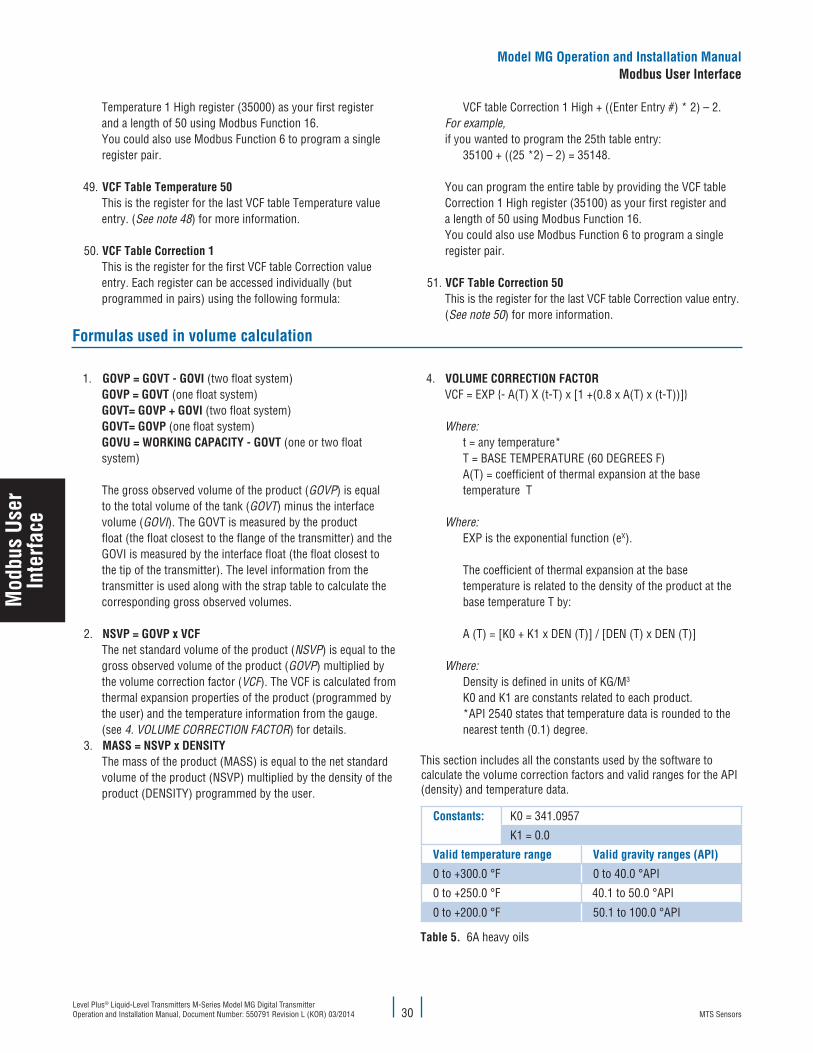
MTS SensorsLevel Plus® Liquid-Level Transmitters M-Series Model MG Digital Transmitter Operation and Installation Manual, Document Number: 550791 Revision L (KOR) 03/2014
Mod
bus
User
Inte
rface
Model MG Operation and Installation ManualModbus User Interface
30
Temperature 1 High register (35000) as your first register and a length of 50 using Modbus Function 16. You could also use Modbus Function 6 to program a single register pair.
49. VCF Table Temperature 50 This is the register for the last VCF table Temperature value entry. (See note 48) for more information.
50. VCF Table Correction 1 This is the register for the first VCF table Correction value entry. Each register can be accessed individually (but programmed in pairs) using the following formula:
VCF table Correction 1 High + ((Enter Entry #) * 2) – 2. For example, if you wanted to program the 25th table entry: 35100 + ((25 *2) – 2) = 35148. You can program the entire table by providing the VCF table Correction 1 High register (35100) as your first register and a length of 50 using Modbus Function 16. You could also use Modbus Function 6 to program a single register pair.
51. VCF Table Correction 50 This is the register for the last VCF table Correction value entry. (See note 50) for more information.
Formulas used in volume calculation
1. GOVP = GOVT - GOVI (two float system) GOVP = GOVT (one float system) GOVT= GOVP + GOVI (two float system) GOVT= GOVP (one float system) GOVU = WORKING CAPACITY - GOVT (one or two float system) The gross observed volume of the product (GOVP) is equal to the total volume of the tank (GOVT) minus the interface volume (GOVI). The GOVT is measured by the product float (the float closest to the flange of the transmitter) and the GOVI is meas ured by the interface float (the float closest to the tip of the transmitter). The level information from the transmitter is used along with the strap table to calculate the corresponding gross observed volumes.
2. NSVP = GOVP x VCF The net standard volume of the product (NSVP) is equal to the gross observed volume of the product (GOVP) multiplied by the volume correction factor (VCF). The VCF is calculated from thermal expansion properties of the product (programmed by the user) and the temperature information from the gauge. (see 4. VOLUME CORRECTION FACTOR) for details.
3. MASS = NSVP x DENSITY The mass of the product (MASS) is equal to the net standard volume of the product (NSVP) multiplied by the density of the prod uct (DENSITY) programmed by the user.
4. VOLUME CORRECTION FACTOR VCF = EXP - A(T) X (t-T) x [1 +(0.8 x A(T) x (t-T))] Where: t = any temperature* T = BASE TEMPERATURE (60 DEGREES F) A(T) = coefficient of thermal expansion at the base temperature T Where: EXP is the exponential function (eX). The coefficient of thermal expansion at the base temperature is related to the density of the product at the base temperature T by: A (T) = [K0 + K1 x DEN (T)] / [DEN (T) x DEN (T)] Where: Density is defined in units of KG/M3 K0 and K1 are constants related to each product. *API 2540 states that temperature data is rounded to the nearest tenth (0.1) degree.
This section includes all the constants used by the software to calculate the volume correction factors and valid ranges for the API (density) and temperature data.
Constants: K0 = 341.0957
K1 = 0.0
Valid temperature range Valid gravity ranges (API)
0 to +300.0 °F 0 to 40.0 °API
0 to +250.0 °F 40.1 to 50.0 °API
0 to +200.0 °F 50.1 to 100.0 °API
Table 5. 6A heavy oils

MTS SensorsLevel Plus® Liquid-Level Transmitters M-Series Model MG Digital Transmitter
Operation and Installation Manual, Document Number: 550791 Revision L (KOR) 03/201431
FORMULAS USED IN VOLUME CALCULATIONS (CONTINUED)
Product type ConstantsValid gravity range (API)
Fuel oil K0 = 103.8720K1 = 0.2701
0.0 to 37.0 °API
Jet group K0 = 330.3010K1 = 0.0
37.1 to 47.9 °API
Transition group K0 = 1489.0670K1 = -0.0018684
48.0 to 52.0 °API
Gasoline K0 = 192.4571K1 = 0.2438
52.1 to 85.0 °API
Valid temperature ranges Valid TEC ranges
0 to +300.0 °F 0 to 40.0 °API
0 to +250.0 °F 40.1 to 50.0 °API
0 to +200.0 °F 50.1 to 85.0 °API
Table 6. 6B light oils
Valid temperature range Valid TEC ranges
0 to +300.0 °F 270.0 to 510.0 * 10E-6/ °F
0 to +250.0 °F 510.5 to 530.0 * 10E-6/ °F
0 to +200.0 °F 530.5 to 930.0 * 10E-6/ °F*For the transition group, A(T) = [K1 + K0 (DEN (T) x DEN (T))]**TEC is the thermal expansion coefficient of the product being measured
Table 7. 6C chemicals
Valid temperature range Valid TEC ranges
0 to +300.0 °F 100.0 to 999.0 * 10E-6/ °F*For the transition group, A(T) = [K1 + K0 (DEN (T) x DEN (T))
Table 8. 6C MOD
Note:
Volumetric modes 6C MOD and CUST TAB are not intended for custody transfer applications since they do not follow API standard 2540 exactly. The software for 6C MOD incorporates a moveable terperature reference and allows for a wider range of TEC values.
Installing the M-Series Digital Setup Software
Adjustments to the calibration and set up parameters of the transmitter can be performed using the M-Series Digital Setup Software package. The software can be run from any PC using a RS-485 to RS-232 converter (See Table 9 MTS part number references). In the ‘MTS Digital Gauge Configuration - Modbus -COM’ window, you will see two tabs labeled ‘Data From Device’ (see Figure 14 ) on page 32 and ‘Volume Calculations’ (see Figure 15 on page 32). You will use these tabs to calibrate the transmitter and change setup parameters.
Note:
You must use a RS-485 converter with ‘Send Data Control’ when using the M-Series Digital Setup software to ensure proper operation. Example: B & B Electronics 485BAT3 (815-433-5100 www.bb-elec.com).
M-Series PC Digital Setup Software (Modbus) CD and RS-485 to RS-232 converter M-Series PC Digital Setup Software (Modbus) CD RS-485 to RS-232 converterOrder number: 625051 Order number: 625052 Order number: 380075
Table 9. MTS part number references
Perform the following steps to install the transmitter setup software to establish communications with the transmitter:
1. Install Setup Software from the CD that came with your transmitter or go to www.mtssensors.com to download the latest version.2. Connect transmitter to the RS-485 to RS-232 converter and attach the converter to your PC. Some PC’s will require an additional Serial
to USB converter.3. Open the Software program.4. Select COM Port. If you do not know which COM port to select, right click My Computer and select Properties -> Hardware Tab ->
Device Manager -> Ports (COM & LPT) to view the list.5. Click the Device: pull-down window and select the ‘transmitter address’, the factory default for Modbus is 247.
Model MG Operation and Installation ManualModbus User Interface
Mod
bus
User
Inte
rface
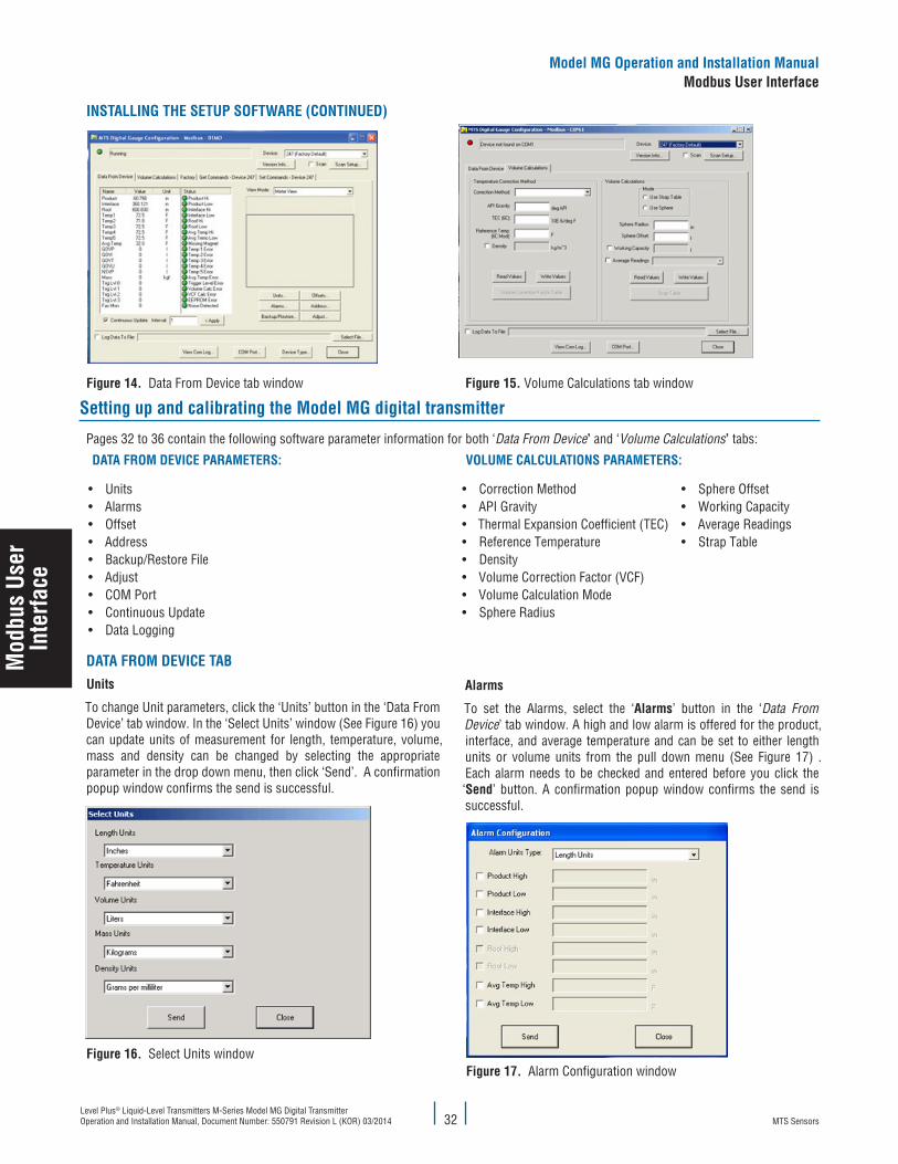
MTS SensorsLevel Plus® Liquid-Level Transmitters M-Series Model MG Digital Transmitter Operation and Installation Manual, Document Number: 550791 Revision L (KOR) 03/2014
Mod
bus
User
Inte
rface
Model MG Operation and Installation ManualModbus User Interface
32
INSTALLING THE SETUP SOFTWARE (CONTINUED)
Figure 14. Data From Device tab window Figure 15. Volume Calculations tab window
Setting up and calibrating the Model MG digital transmitter
Pages 32 to 36 contain the following software parameter information for both ‘Data From Device’ and ‘Volume Calculations’ tabs:
DATA FROM DEVICE PARAMETERS: VOLUME CALCULATIONS PARAMETERS:
• Units• Alarms• Offset• Address• Backup/Restore File• Adjust• COM Port • Continuous Update• Data Logging
• Correction Method• API Gravity• Thermal Expansion Coefficient (TEC)• Reference Temperature• Density• Volume Correction Factor (VCF)• Volume Calculation Mode• Sphere Radius
• Sphere Offset• Working Capacity• Average Readings• Strap Table
DATA FROM DEVICE TABUnits
To change Unit parameters, click the ‘Units’ button in the ‘Data From Device’ tab window. In the ‘Select Units’ window (See Figure 16) you can update units of measurement for length, temperature, volume, mass and density can be changed by selecting the appropriate parameter in the drop down menu, then click ‘Send’. A confirmation popup window confirms the send is successful.
Figure 16. Select Units window
Alarms
To set the Alarms, select the ‘Alarms’ button in the ‘Data From Device’ tab window. A high and low alarm is offered for the product, interface, and average temperature and can be set to either length units or volume units from the pull down menu (See Figure 17) . Each alarm needs to be checked and entered before you click the ‘Send’ button. A confirmation popup window confirms the send is successful.
Figure 17. Alarm Configuration window

MTS SensorsLevel Plus® Liquid-Level Transmitters M-Series Model MG Digital Transmitter
Operation and Installation Manual, Document Number: 550791 Revision L (KOR) 03/201433
DATA FROM DEVICE TAB (CONTINUED)
Calibration
When you click the ‘Offset’ button in the ‘Data From Device’ tab window, the ‘Offsets’ window opens. There are two calibration ‘Offset Methods’ to choose from, ‘Enter Current Tank Level’ and ‘Enter Level Offset’. Click to open the ‘Offset Method:’ drop down menu and select a calibration method. Choose either method ‘Enter Current Tank Level’ or ‘Enter Current Interface Level’ and type a value in the active field, then click the ‘Send’ button. A confirmation popup window confirms the send is successful.
Figure 18. Offsets window - Enter Current Tank Level
When you choose ‘Enter Level Offset’ from the ‘Offset Method:’ drop down menu, you can adjust the offset where the transmitters zero point is located. This adjustment will significantly shorten the span of the transmitter or counter inactive zones. Adjust the value accordingly and click ‘Send’. A confirmation popup window confirms the send is successful.
Figure 19. Offsets window - Enter Level Offset method
Address
To change the transmitter address, click the ‘Address’ button in the ‘Data From Device’ tab window. In the ‘Change Address’ window, type the ‘New Address’ in the active field and click ‘Send’. A confirmation popup window confirms the send is successful.
Figure 20. Change Address window - New Address entry
Backup / Restore File
If your electronics requires a replacement or if your current settings need to be refreshed, it is recommended that you create a backup or restoration file. To create a backup, click the ‘Backup/Restore’ button in the ‘Data From Device’ tab window . In the ‘Backup and Restore Device Settings” window, click the ‘Get Data From Sensor’ button and ‘Save Settings to File’ button. When prompted, save the file to a designated place where you can find it. To upload a file, click the ‘Read Settings from File’ button and select your backup file. Click ‘Write Data to Sensor’. A confirmation popup window confirms the upload is successful.
Figure 21. Backup and Restore Device Settings window
Adjust
To adjust the Gain, click the ‘Adjust’ button located in the ‘Data From Device’ tab window. The ‘Modbus Adjust Gain’ window displays dif-ferent parameter settings depending on the firmware of the transmit-ter. All transmitters will have the ability to adjust the ‘Gain’ from this menu. Other transmitters will have the ability to adjust the gain, and display the following; magnet blanking, delta, and blanking reference. None of these parameters should be changed without MTS Technical Support and are password protected. ~mtsdda~
Figure 22. Modbus Adjust Gain window
Model MG Operation and Installation ManualModbus User Interface
Mod
bus
User
Inte
rface

MTS SensorsLevel Plus® Liquid-Level Transmitters M-Series Model MG Digital Transmitter Operation and Installation Manual, Document Number: 550791 Revision L (KOR) 03/2014
Mod
bus
User
Inte
rface
Model MG Operation and Installation ManualModbus User Interface
34
DATA FROM DEVICE TAB (CONTINUED)
COM Port
To select the Setup Software communication port, click the ‘COM Port’ button in the ‘Data From Device’ tab window. Select the appropriate communication port and click ‘OK’.
Figure 23. Select a COM Port window
Continuous Update
To view realtime data using the Setup Software interface, select the ‘Continuous Update’ box. The Interval may be changed to slow down updates but is not necessary.
Data Logging
To download a transmitter data log, Click ‘Select File’ in the ‘Data From Device’ tab window. Select an Excel file and check the ‘Log Data to File’ box to save your data.
Volume Calculations tab
tors. Once the file is created it can be saved to a file and kept on a computer for safe keeping or transferred to multiple transmitters. Before closing the user must click ‘Send’ to send the VCF table to the transmitter.
Figure 24. Volume Correction Factor Table window
Volume Calculation Mode
Select between ‘Use Sphere’ and ‘Use Strap Table’ as the volume calculation mode.
Sphere Radius
Enter the radius of the sphere the transmitter is mounted in.
Sphere Offset
In the ‘Sphere Offset’ field, enter the ‘sphere offset parameter’ which is used to add or subtract a fixed volume from the calculated sphere volume. This parameter is typically used to account for volume er-rors created by non-uniform sphere geometry (i.e. Flat bottoms or internal structures)
Note:
As a first step always press the ‘Read’ button to determine the trans-mitter’s current configuration. After editing any parameters always press the ‘Write’ button to program the transmitter.
Correction Method
The correction method is selected by clicking the pull down menu and selecting the appropriate correction method. Available selections include 6A (Heavy Oils), 6B (Light Oils), 6C (Chemical), 6C Mod, Custom Table, and Disabled. If ‘Custom Table’ is chosen, you must click ‘Volume Correction Factor Table’ and enter the table.
API Gravity
Enter the ‘API gravity’ (normalized density) value for the product being measured in the applicable field. Allowable values are:
6A - 0.0 deg to 100.0 deg API 6B - 0.0 deg to 85.0 deg API
TEC (Thermal Expansion Coefficient)
Temperature Correction Method ‘6C’ uses the thermal expansion coefficient of the product being measured to determine the volume correction factor. Allowable values are 270.0 to 930.0. TEC units are in 10 E-6/deg F. In the ‘TEC (6C)’ field, enter the appropriate value.
Reference Temperature
When selecting correction method 6C Mod you will need to enter the desired base temperature for the volume calculations in the
‘Reference Temperature’ field. The allowable values are 32 deg F to 150 deg F.
Density
Entering a density is required when using Temperature Correction Method ‘6C’ or ‘Custom Table’ for net mass calculations. The density measurement should be entered as ‘LB/cu.ft’. at the given reference temperature.Volume Correction Factor Table
When Custom Table is chosen as the temperature correction method the user has to enter the volume correction factor table. The table will hold up to 50 entries of temperature points and correction fac-

MTS SensorsLevel Plus® Liquid-Level Transmitters M-Series Model MG Digital Transmitter
Operation and Installation Manual, Document Number: 550791 Revision L (KOR) 03/201435
VOLUME CALCULATIONS TAB (CONTINUED)
Working Capacity
In the working capacity field, enter the volume of safe fill level using the same units defined in the strap table. to calculate Gross Observed Volume Ullage (GOVU).
Average Readings
In the ‘Average Ratings’ pull-down menu, select from preset averaging for the data being calculated. Selections are available from 5 to 60 seconds.
Strap Table
When selecting the ‘Use Strap Table’ volume calculation mode the user must enter a strap table. The model MG with Modbus is capable of handling a 100 point strap table. To enter a strap table click ‘Strap Table’ and click ‘Add’ to start entering each volume and distance point. Once the strap table is entered save a copy to your PC by clicking ‘Write to File.’ Before closing the user must click ‘Send’ to send the strap table to the transmitter. Straptable default password is ‘becareful’.
Model MG Operation and Installation ManualModbus User Interface
Mod
bus
User
Inte
rface

MTS SensorsLevel Plus® Liquid-Level Transmitters M-Series Model MG Digital Transmitter Operation and Installation Manual, Document Number: 550791 Revision L (KOR) 03/2014 36
FOUNDATION™ fieldbus interface
FOUNDATION™ fieldbus is an open, integrated total architecture for information integration that is an all digital, two way communication system. A differentiator for FOUNDATION™ fieldbus is it’s built in capability to distribute the control application across the network. The model MG transmitter interfaces via H1 that interconnects field devices at 31.25 kbit/s.
The H1 FOUNDATION™ Fieldbus retains and optimizes the desirable features of the 4 to 20 mA analog system such as:
• Single loop integrity• A standardized physical interface to the wire• Bus-powered devices on a single wire pair• Intrinsic safety options
Device description
The Device Description (DD) file provides information needed for a control system or host to understand the meaning of the data from the field device. DD files are platform and operating system independent so any control system or host can operate a device if it has the device’s DD files. The DD files are similar to the drivers that a PC uses to operate printers, USB’s, and other devices. Current DD files are available for download from http://www.fieldbus.org.
Transducer block
The model MG transmitter contains two transducers blocks: Setup and Factory. All of the information and functions needed to setup, calibrate, and troubleshoot the model MG are located in the transducer blocks. Please contact Technical Support for help before changing parameters in the transducer blocks. Some of the parameters are password protected for the end users’ benefit.
SETUP TRANSDUCER BLOCK
Index Parameter mnemonic Description
1 ST_REV
2 TAG_DESC
3 STRATEGY
4 ALERT_KEY
5 MODE_BLK
6 BLOCK_ERR
7 UPDATE_EVT
8 BLOCK_ALM
9 TRANDUCER_DIRECTORY
10 TRANSDUCER_TYPE
11 XD_ERROR
12 COLLECTION_DIRECTORY
SETUP TRANSDUCER BLOCK
Index Parameter mnemonic Description
Dynamic variables (Setup transducer block)
13 PRODUCT_LEVEL_AI Output Level 1 (Product)
14 INTERFACE_LEVEL_AI Output Level 2 (Interface)
15 AVERAGE_TEMPERATURE Output Average Temp of submersed DTs (Temperature sensors)
16 NSVP NSVP = GOVP x VCF(Volume Correction Factor)
17 GOVP GOVP = Total Volume - Interface Volume
18 GOVI GOVI = Interface Volume
20 TEMPERATURE1 DT 1 (Temperature sensor 1)
21 TEMPERATURE2 DT 2 (Temperature sensor 2)
22 TEMPERATURE3 DT 3 (Temperature sensor 3)
23 TEMPERATURE4 DT 4 (Temperature sensor 4)
24 TEMPERATURE5 DT 5 (Temperature sensor 5)
25 GOVT GOVT = GOVP - GOVI
26 GOVU GOVU = Working capacity - GOVT
27 MASS MASS = NSVP x Density

MTS SensorsLevel Plus® Liquid-Level Transmitters M-Series Model MG Digital Transmitter
Operation and Installation Manual, Document Number: 550791 Revision L (KOR) 03/201437
SETUP TRANSDUCER BLOCK
Index Parameter mnemonic Description
Setup parameters (Setup transducer block)
28 TEMP_CORR_METHOD There are five methods to choose from:1 = Heavy Oils2 = Light Oils3 = Chemicals4 = Chemicals with wider coefficients than 6C and a movable reference temperature5 = custom table
29 API_GRAVITY Normalized Density value
30 WORKING_CAPACITY Working capacity of tank
31 TEC Thermal correction method 6C uses the thermal expansion coefficient of the product being measured to determine the volume cor-rection factor. Allowable values are 270.0 to 930.0 TEC Units. TEC Units are in 10E-6/DegF.
32 DENSITY Temperature correction method 6C and “custom table” requires you to enter the density (at a given reference temperature) of the product being measured.
33 REF_TEMPERATURE This is the desired base temperature for the VCF calculation when Temperature Correction Method 4 (6C Wide) is used.
34 VOL_CALC_MODE This is the mode you wish the volume calculations to be performed by:1 = Use Strap Table0 = Use Sphere Calcula-tions
35 SPHERE_RADIUS The radius of the sphere when volume calculations are performed (using the sphere calculation mode).
36 SPHERE_OFFSET The offset of the sphere when volume calculations are performed (using the sphere calculation mode).
37 AVERAGE_INTERVAL All level, temperature, and volume calculations can be averaged using timed method.
38 ALARM_STATUS
SETUP TRANSDUCER BLOCK
Index Parameter mnemonic Description
39 VCF_COR_ERR_STATUS If there is no error performing the volume correction factor then the value is zero otherwise the value is a non-zero code.
40 VOL_CAL_ERR_STATUS If there is no error performing the volume calculations then the value is zero otherwise the value is a non-zero code.
41 TEMP_UNITS Celsius, Fahrenheit
42 DENSITY_UNITS Grams per Mil-liliter, Grams per Liter, Kilograms per Cubic Meter, Kilograms per Liter, Pounds per Cubic Inch, Pounds per Cubic Foot, Pounds per Gallon, Metric Tonnes per Cubic Meter, Tons per Cubic Yard
43 VOLUME_UNITS Liters, Cubic Millimeters, Cubic Meters, Cubic Inches, Cubic Feet, Gal-lons, or Barrels
44 LENGTH_UNITS Millimeters, Centimeters, Meters, Kilometers, Inches, Feet, or Yards
45 MASS_UNITS Kilograms, Grams, Ounces, Pounds, Tons, or Metric Tonnes
46 TANK_OFFSET This is the value that will be added or subtracted from the level measure-ment. This allows the tank level reading to be calibrated to the users gauged tank reading (or other reference guide.)
47 INTERFACE_TANK_OFFSET This is the value that will be added or sub-tracted from the interface measurement. This allows the tank interface reading to be calibrated to the users gauged tank reading (or other reference guide.)
(Transducer block - Setup parameters continued on next page)

MTS SensorsLevel Plus® Liquid-Level Transmitters M-Series Model MG Digital Transmitter Operation and Installation Manual, Document Number: 550791 Revision L (KOR) 03/2014
SETUP TRANSDUCER BLOCK
Index Parameter mnemonic Description
Setup parameters (Setup transducer block) continued
48 CAL_CURRENT_PROD_LEV
This is used to calibrate the level measurement. This allows the user to enter the hand gauged tank reading (or other level reference guide) of the Product and the device will calculate the necessary calibration offset. The calculated value will then be stored as the “Tank Offset”.)
49 CAL_CURRENT_ INTER_LEV
This is used to calibrate the level measurement. This allows the user to enter the hand gauged tank reading (or other level reference guide) of the Interface and the device will calculate the necessary calibration offset. The calculated value will then be stored as the “Tank Offset”.)
50 ALARM_UNITS This parameter the unit type for which you can program the alarm. Product and Interface can be “volume” or “length” unit types, however Roof can only be “Length” unit type.
51 INTERFACE_HI_ALM The value for which the Interface cannot be >=. Make sure that the value is programmed in the current Alarm unit type.
52 INTERFACE_LO_ALM The value for which the Interface cannot be <=. Make sure that the value is programmed in the current Alarm unit type.
53 PRODUCT_HI_ALM The value for which the Product cannot be >=. Make sure that the value is programmed in the current Alarm unit type.
54 PRODUCT_LO_ALM The value for which the Product cannot be <=. Make sure that the value is programmed in the current Alarm unit type.
57 TEMP_AVR_HI_ALM The value for which the Average Temperature cannot be >=.
58 TEMP_AVR_LO_ALM The value for which the Average Temperature cannot be <=.
SETUP TRANSDUCER BLOCK
Index Parameter mnemonic Description
59 NUM_STRAP_TAB_ ENTRIES
The value specifies the number of strap table entries to be used in the tank-strapping table. Table size can range from 2 to 100 entries
60 - 63
STRAP_TAB_LEVEL
64 - 67
STRAP_TAB_VOL
68 NUM_VCF_TAB_ENTRIES The value specifies the number of VCF table entries to be used in the volume correction factor table. Table size can range from 2 to 50 entries
69 - 70
VCF_TAB_TEMP
71 - 72
VCF_TAB_CORR
FACTORY TRANSDUCER BLOCK
Index Parameter Mnemonic Description
1 1ST_REV
2 TAG_DESC
3 STRATEGY
4 ALERT_KEY
5 MODE_BLK
6 BLOCK_ERR
7 UPDATE_EVT
8 BLOCK_ALM
9 TRANDUCER_DIRECTORY
10 TRANSDUCER_TYPE
11 XD_ERROR
12 COLLECTION_DIRECTORY
13 PASSWORD Password, 43991
14 REG_MEAS_LENGTH Length of the Transmitter
15 REG_SER_NO Serial Number
16 REG_SW_REV Software Revision
17 REG_GRADIENT Gradient
18 REG_NUM_TEMPS Number of DT’s
19 REG_SIGNAL_GAIN Signal Gain
20 REG_MIN_TRIG_LEVEL Min Trigger Level
21 REG_TRANSMIT_DELAY Transmission Delay, Always 0
22 REG_SARA_BLANKING SARA Blanking23 REG_MAGNET_BLANKING Magnet Blanking24 REG_DELTA Delta
25 REG_MEAS_INTER-FACE_FIRST Measure Interface First
38

MTS SensorsLevel Plus® Liquid-Level Transmitters M-Series Model MG Digital Transmitter
Operation and Installation Manual, Document Number: 550791 Revision L (KOR) 03/2014
FACTORY TRANSDUCER BLOCK
Index Parameter Mnemonic Description26 REG_FLOAT_CONFIG Float Configuration27 REG_DIG_TEMP_POS1 Digital Temp Position 1
28 REG_DIG_TEMP_INTER-CEPT1 Digital Temp Intercept 1
29 REG_DIG_TEMP_SLOPE1 Digital Temp Slope 130 REG_DIG_TEMP_POS2 Digital Temp Position 2
31 REG_DIG_TEMP_INTER-CEPT2 Digital Temp Intercept 2
32 REG_DIG_TEMP_SLOPE2 Digital Temp Slope 233 REG_DIG_TEMP_POS3 Digital Temp Position 3
34 REG_DIG_TEMP_INTER-CEPT3 Digital Temp Intercept 3
35 REG_DIG_TEMP_SLOPE3 Digital Temp Slope 3
FACTORY TRANSDUCER BLOCK
Index Parameter Mnemonic Description36 REG_DIG_TEMP_POS4 Digital Temp Position 4
37 REG_DIG_TEMP_INTER-CEPT4 Digital Temp Intercept 4
38 REG_DIG_TEMP_SLOPE4 Digital Temp Slope 439 REG_DIG_TEMP_POS5 Digital Temp Position 5
40 REG_DIG_TEMP_INTER-CEPT5 Digital Temp Intercept 5
41 REG_DIG_TEMP_SLOPE5 Digital Temp Slope 542 REG_TRIGGER_LEV043 REG_TRIGGER_LEV144 REG_TRIGGER_LEV245 REG_TRIGGER_LEV346 NUM_TEMP_AVR_HI Num Temp Average
Analog input function blocks
The Model MG transmitter contains 6 Analog Inputs with the output options of product, interface, average temperature, NSVP, GOVP, and GOVI. The Interface and GOVI Analog Inputs require the trans-mitter to be configured for measuring product and interface levels. To perform a quick configuration of the function blocks configure the following:
Channel
Analog Input Channel # Units
Product 1 Length units
Interface 2 Length units
Average Temperature 3 Temperature units
NSVP 4 Volume units
GOVP 5 Volume units
GOVI 6 Volume units
Linearization Type
Direct Choose direct when the output is the transmitter’s value.
Indirect Choose indirect when the output is calculated based off of the transmitter’s value and the relation-ships is linear, i.e. 0 to 100%
Indirect Square Root
Choose indirect square root when the output is calculated based off of the transmitter’s and the output is the square root of the transmitter’s value.
Transducer Scale and Output Scale
Direct Transducer Scale and Output Scale do not need to be configured.
Indirect or Indirect Square Root
The transducer scale should be set to the full operating range that the transmitter will see during use. The output scale should contain the values that would be outputted when the transducer scale is at its minimum and maximum. The relationship is linear.
The Transducer Scale and Output Scale can also be configured to display in set units and with a set number of significant digits.
Transducer Scale units will be the same as the units programmed into the transmitter; the default settings are Inches for length, Fahrenheit for temperature, and Gallons for volume. Units can be changed under MTS_SETUP_TB -> Setup Parameters -> Data from device
-> Units. It is best to double check the units in the transmitter and the Transducer Scale incase someone has changed them accidently.
Example 1: Output of product level
Parameter Configured Value
Channel 1 - ProductLinearization Type DirectTransducer Scale: EU at 100% N/ATransducer Scale: EU at 0% N/ATransducer Scale: Units Index N/ATransducer Scale: Decimal N/AOutput Scale: EU at 100% N/AOutput Scale: EU at 0% N/A
Output Scale: Units Index N/AOutput Scale: Decimal N/A
Example 2: Output of Product Level in Percent for 10 m (33 ft.) Transmitter
Parameter Configured Value
Channel 1 - ProductLinearization Type IndirectTransducer Scale: EU at 100% 396Transducer Scale: EU at 0% 0Transducer Scale: Units Index InTransducer Scale: Decimal 3Output Scale: EU at 100% 100Output Scale: EU at 0% 0Output Scale: Units Index %Output Scale: Decimal 3
39

MTS SensorsLevel Plus® Liquid-Level Transmitters M-Series Model MG Digital Transmitter Operation and Installation Manual, Document Number: 550791 Revision L (KOR) 03/2014 40
Resource blockThe Resource Block describes characteristics of the Fieldbus device such as the device name, manufacturer, and serial number. A device has only one Resource Block.
LAS/Back-up LAS
The model MG transmitter is designed as a Link Master and can be used as a primary or secondary Link Active Scheduler (LAS). For the majority of networks the host system will be the primary LAS with a field device acting as secondary LAS in the event that the primary LAS fails. The typically use of the model MG transmitter will be as a secondary LAS for back-up.
Setup and calibration
Setup and Calibration can be conducted from any host with a different process. Below are common parameters that will need to be changed. Please consult the Transducer Block section to locate the parameters. Specific parameters are password protected to keep users from ac-cidently changing factory parameters that should not be changed unless advised by Technical Support.
Note:
The mode will have to be changed to Out of Service (OOS) when editing parameters. When making this change most host systems will warn you that this may upset the process and create a dangerous situation in your plant. Before making the change to OOS, verify that taking the transmitter out of service will not negatively affect control of the plant.
UNITS
The model MG transmitter allows the user to select the units for length, temperature, volume, mass, and density.
TEMP_UNITS Celsius, Fahrenheit
DENSITY_UNITS Grams per Milliliter, Grams per Liter, Kilograms per Cubic Meter, Kilograms per Liter, Pounds per Cubic Inch, Pounds per Cubic Foot, Pounds per Gallon, Metric Tonnes per Cubic Meter, Tons per Cubic Yard
VOLUME_UNITS Liters, Cubic Millimeters, Cubic Meters, Cubic Inches, Cubic Feet, Gallons, or Barrels
LENGTH_UNITS Millimeters, Centimeters, Meters, Kilometers, Inches, Feet, or Yards
MASS_UNITS Kilograms, Grams, Ounces, Pounds, Tons, or Metric Tonnes
CALIBRATION
Calibration can be done either using the current tank level or entering an offset for both the product and interface level. The TANK_OFFSET and INTERFACE_TANK_OFFSET contain values that adjust the refer-ence point for the zero point on the transmitter. By adjusting the offsets up or down the user can change the value the transmitter outputs. This process is harder then it sounds and Technical Support should be contacted before proceeding.
An alternative method of calibration is to use CAL_CURRENT_PROD_LEV and CAL_CURRENT_INTER_LEV to calibrate the product and interface levels respectively. In order to do so the tank should be static and the user can hand gauge the tank. The user can then take the hand gauge measurement and input it into the transmitter. Make sure that the level does not move from the time the measurement is taken until the transmitter is calibrated. The transmitter will take the current level that is entered and calculate the offsets for the user.
VOLUME CALCULATION
The model MG will calculate the volume of the vessel using either a sphere or a strap table formula. The user can choose which method by selecting a 1 for Strap Table or a 0 for a Sphere under VOL_CALC_MODE. When selecting to use the Sphere method the user will have to enter the SPHERE_RADIUS and SPHERE_OFFSET. Despite which method is chosen, the user should enter the WORK-ING_CAPACITY and AVERAGE_INTERVAL.
When the user selects to calculate volume based off of a strap table the user will need to enter the strap table. The first step is to enter the NUM_STRAP_TAB_ENTRIES between 2 and 100. For each strap table point the user will have to enter the STRAP_TAB_LEVEL and STRAP_TAB_VOL for every entry.
TEMPERATURE CORRECTION METHOD
The TEMP_CORR_METHOD is selected by selecting the appropriate correction method. Available selections include:
1 = 6A (Heavy Oils)2 = 6B (Light Oils)3 = 6C (Chemical)4 = 6C Mod5 = Custom Table
If Custom Table is chosen the user will need to enter the NUM_VCF_TAB_ENTRIES.
Enter the API_GRAVITY (normalized density) value for the product being measured in the applicable field. Allowable values are:
6A - 0.0 deg to 100.0 deg API 6B - 0.0 deg to 85.0 deg API
TEC (Temperature Correction Method) 6C uses the thermal expansion coefficient of the product being measured to determine the volume

MTS SensorsLevel Plus® Liquid-Level Transmitters M-Series Model MG Digital Transmitter
Operation and Installation Manual, Document Number: 550791 Revision L (KOR) 03/201441
correction factor. Allowable values are 270.0 to 930.0. TEC units are in 10 E-6/deg F. In the TEC (6C) field, enter the appropriate value.
When selecting correction method 6C Mod you will need to enter the desired base temperature for the volume calculations in the REF_TEMPERATURE. The allowable values are 32 deg F to 150 deg F.
Entering a DENSITY is required when using Temperature Correction Method 6C or Custom Table for net mass calculations. The density measurement should be entered as LB/cu.ft. at the given reference temperature.
Password Settings - Gradient - Serial Number - Software Revision - Number of DT’s - Signal Gain - Min Trigger Levels - Transmission Delay - SARA Blanking - Magnet Blanking - Delta - Measure Interface First Digital Temperature Setup - Number of DT’s - Enter Temperature Points Float Configuration Set Trigger Levels
When the user selects to calculate temperature correction based off of a custom table the user will need to enter the custom table. The first step is to enter the NUM_VCF_TAB_ENTRIES between 2 and 50. For each custom table point the user will have to enter the VCF_TAB_TEMP and VCF_TAB_CORR for every entry.
FOUNDATION fieldbus handheld menu tree
MTS_SETUP_TB
FB dynamic variablesOther dynamic variablesAlarm Status - Alarm Status - VCF Calc Error Status - Volume Calc ErrorSetup Parameters - Data from device Units - Length Units - Temperature Units - Volume Units - Mass Units - Density Units Alarms Offsets - Enter Product Offset - Enter Interface Offset - Enter Current Product Level - Enter Current Interface Level - Volume Calculations Temperature Correction Methods - Temperature Correction Method - API Gravity - TEC (6C) - Ref Temperature (6C Mod) - Density - Custom Table -Num of VCF table entries -Enter Custom Table -VCF Corr Table: Temperature -VCF Corr Table: Correction Factor Volume Calculations - Mode - Working Capacity - Average Interval
MTS_FACTORY_TB

MTS SensorsLevel Plus® Liquid-Level Transmitters M-Series Model MG Digital Transmitter Operation and Installation Manual, Document Number: 550791 Revision L (KOR) 03/2014
DDA interface
42
Data line termination and biasing:
Termination and biasing of RS-485 data lines are as follows: • Biasing Each M-Series transmitter has internal high impedance biasing resistors (30K Ω) on both RS-485 data lines. No additional biasing resistors should be present on the connecting devices (PLC, DCS, PC, converter).• Termination Each M-Series transmitter has an internal termination resistor (100K Ω) installed across the RS-485 signal lines. No additional termination resistors are necessary in the connecting devices (PLC, DCS, PC, converter).
Communication parameters:
The 2-wire differential communication interface and all data transmissions must be at half duplex. Only one device (either the master or a single transmitter) can transmit data at any given time. BAUD rate limitations are listed below.
Modbus: 4800 or 9600 BAUD 8, N, 1DDA: 4800 BAUD 8, E, 1(Reference) Monitor: Modbus RTU Variable BAUD Rate 8, E, 1
Hardware and software environments
The Level Plus Model MG digital transmitter operates in a net-worked, intrinsically safe RS-485 DDA software environment. This environment supports up to 8 multi-dropped transmitters on one communication line. The network requires a 4-wire bus to provide both power and communications to each of the transmitters located in the hazardous area. The transmitters are connected in multi-point configuration (see Figure 25).
The RS-485 network operates in a master/slave mode where the master (host computer or similar type network controller) inter-rogates each slave (DDA transmitter) for a specific type of data. Each slave has a unique switch programmable hardware address that is
by the host computer to activate a particular transmitter. In addition, the DDA hardware supports a command decoder that supports up to 128 different commands. The host computer interrogates a transmit-ter for data by sending an address byte, followed immediately by a command byte. The addressed transmitter will ‘wake up’, identify itself by transmitting an echo of its own local address followed by the received command, and then perform the requested action. After the requested action has been completed, the data (if any) will be transmitted back to the host computer on the RS-485 network. Refer to Section ‘DDA Command decoder examples’ on page 43 for more information.
. . .
2
2
+24 Vdcpowersupply
RS-485Examples:
PC, PLC, DCS
I.S.B.*
Approved intrinsicsafety barrier(3 required)
General application
4-wire bus
Intrinsicallysafe area
Maximum stublength = 200 feet
Up to 8M-Series digital
transmitters(DDA interface)
Figure 25. Typical Electrical Connections - Intrinsically Safe System

MTS SensorsLevel Plus® Liquid-Level Transmitters M-Series Model MG Digital Transmitter
Operation and Installation Manual, Document Number: 550791 Revision L (KOR) 03/201443
DDA command decoder examplesSERIAL DATA TRANSMISSION FORMAT
Example 1: 0 X X X X X X X X P 1
D1 bit Stop bit
Start bit Parity bit D8 bit
After the DDA address decoder circuitry receives the 11-bit word, an even parity check is performed across the 8-bit data field. If a parity error is found, the word is ignored and the decoder circuitry resets for the next trans mission. If the parity check is good, the decoder cir-cuitry checks for a valid address byte. The address decoder circuitry uses the ‘D8’ bit to distinguish the difference between address bytes and command bytes. Address bytes are defined as having the most significant bit ‘D8’ set equal to one. Valid address byte values include ‘C0’ hex to ‘FD’ hex (192 to 253 decimal). Address byte values from 80 hex to ‘BF’ hex are reserved for future use, address byte values ‘FE’ and ‘FF’ hex are reserved for test functions. (see Example 2).
ADDRESS BYTE
Example 2: X X X X X X X 1
D8 bit = 1 (8-bit word - shown as D1 bit)
If the received address byte matches the local DDA address, the DDA power supply circuitry is activated. If a valid address byte has been
found, the decoder circuitry checks to see if the next received word is a command byte. Valid command byte values include ‘00’ hex to ‘7F’ hex (0 to 127 decimal). In addition, all data byte values are restricted to be within ‘00’ hex and ‘7F’ hex (see Example 3).
COMMAND BYTE (AND DATA BYTES)
Example 3: X X X X X X X 0
D8 bit = 1 (8-bit word - shown as D1 bit)
Again, an even parity check is performed on the command byte. If the parity check is good, the eight bit data word is latched into a command buffer. This buffer is read by the DDA software to determine which command to execute. If the parity check fails, the command byte is rejected and the old command (from the previous interro gation sequence) will be left in the command buffer. The DDA hardware cannot determine if the current com mand was possibly rejected. The host computer must then verify if the correct command was received by reading the echo of the address byte and command byte sent by the DDA transmitter. This is the only guaranteed way to determine that both the address and command bytes were received properly.
This method also insures proper verification, even if the parity check fails to detect a multiple bit data error in either the address byte or command byte. If the host computer determines that either the address byte or command byte has been corrupted, it must wait the proper time-out period and ignore the received message from the DDA transmitter that was improperly interrogated. The time-out period is variable and is based on the duration of the selected DDA
command.DDA/Host computer communication protocolThe DDA/Host computer communication protocol consists of two parts: the interrogation sequence generated by the host computer and the data response generated by the interrogated DDA transmitter. The host interrogation sequence always consists of an address byte followed immediately by a command byte (see Example 4).
DDA/HOST COMMUNICATION
Example 4:
<address byte><command byte>
00 Hex to 7F Hex (0 to 127 decimal)
C0 Hex to FD Hex (192 to 253 decimal)
The maximum delay between the address byte and the command byte is 5 milliseconds. The DDA transmitter will not receive the new command byte if this delay period is exceed ed (and the old com-mand byte will be left in the command buffer). See previous section for additional information on verification of the Address/Command bytes. An example of an interrogation sequence to access a transmit-ter programmed for address ‘F0’ hex (see Example 5).
The transmitter response consists of several components. After a transmitter has been interrogated, the transmitter first responds by
transmitting its own local address and the command that was re-ceived from the host computer. This re-transmission of the transmit-ter address and received command serves two purposes. The first being a simple identification that the correct transmitter received the correct com mand and that it is currently active. The second purpose is to reset the DDA Address/Command decoder circuitry for the next interrogation sequence.
INTERROGATION DATA SEQUENCE
Example 5:<F0><0A>
Command 0A Hex (10 decimal)
Address F0 Hex (240 decimal)
Note:If the DDA transmitter does not respond to the first interrogation by the host, the Address/Command decoder will be left in an intermedi-ate state. If this occurs, the host will have to reinterrogate the respective transmitter to reset the Address/Command decoder circuitry and then interrogate the respective transmitter again to per form a new transmit-ter measurement. This hardware feature must be considered when writ-ing software communication drivers to access DDA transmitter data.
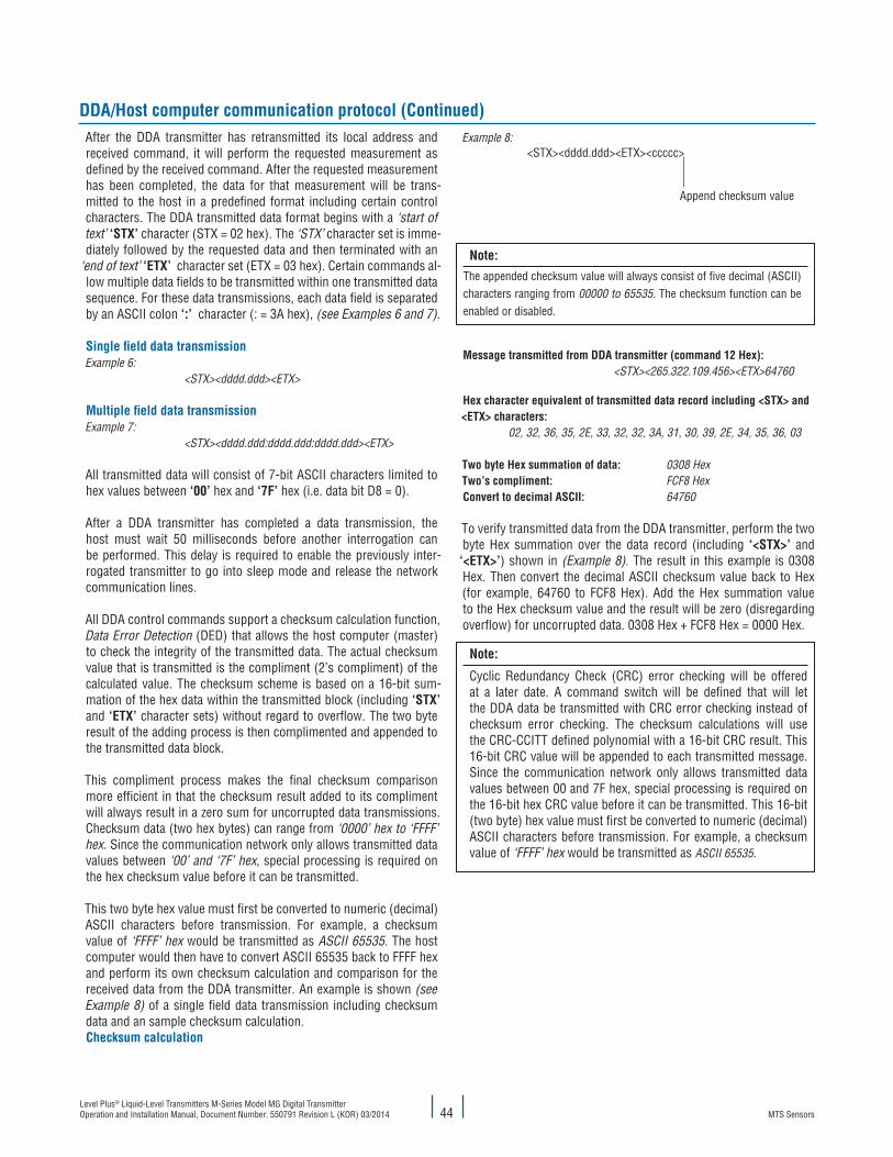
MTS SensorsLevel Plus® Liquid-Level Transmitters M-Series Model MG Digital Transmitter Operation and Installation Manual, Document Number: 550791 Revision L (KOR) 03/2014 44
DDA/Host computer communication protocol (Continued)Example 8:
<STX><dddd.ddd><ETX><ccccc>
Append checksum value
Note:The appended checksum value will always consist of five decimal (ASCII) characters ranging from 00000 to 65535. The checksum function can be enabled or disabled.
Message transmitted from DDA transmitter (command 12 Hex): <STX><265.322.109.456><ETX>64760
Hex character equivalent of transmitted data record including <STX> and <ETX> characters: 02, 32, 36, 35, 2E, 33, 32, 32, 3A, 31, 30, 39, 2E, 34, 35, 36, 03
Two byte Hex summation of data: 0308 HexTwo’s compliment: FCF8 HexConvert to decimal ASCII: 64760
To verify transmitted data from the DDA transmitter, perform the two byte Hex summation over the data record (including ‘<STX>’ and
‘<ETX>’) shown in (Example 8). The result in this example is 0308 Hex. Then convert the decimal ASCII check sum value back to Hex (for example, 64760 to FCF8 Hex). Add the Hex summation value to the Hex checksum value and the result will be zero (disregarding overflow) for uncorrupted data. 0308 Hex + FCF8 Hex = 0000 Hex.
Note:
Cyclic Redundancy Check (CRC) error checking will be offered at a later date. A command switch will be defined that will let the DDA data be transmitted with CRC error checking instead of checksum error checking. The checksum calculations will use the CRC-CCITT defined polynomial with a 16-bit CRC result. This 16-bit CRC value will be appended to each transmitted message. Since the communication network only allows transmitted data values between 00 and 7F hex, special processing is required on the 16-bit hex CRC value before it can be transmitted. This 16-bit (two byte) hex value must first be converted to numeric (decimal) ASCII characters before transmission. For example, a checksum value of ‘FFFF’ hex would be transmitted as ASCII 65535.
After the DDA transmitter has retransmitted its local address and received command, it will perform the requested measurement as defined by the received command. After the requested measurement has been completed, the data for that measurement will be trans-mitted to the host in a predefined format including certain control characters. The DDA transmitted data format begins with a ‘start of text’ ‘STX’ character (STX = 02 hex). The ‘STX’ character set is imme-diately followed by the requested data and then terminated with an
‘end of text’ ‘ETX’ character set (ETX = 03 hex). Certain commands al-low multiple data fields to be transmitted within one transmitted data sequence. For these data transmissions, each data field is separated by an ASCII colon ‘:’ character (: = 3A hex), (see Examples 6 and 7).
Single field data transmissionExample 6: <STX><dddd.ddd><ETX>
Multiple field data transmissionExample 7: <STX><dddd.ddd:dddd.ddd:dddd.ddd><ETX>
All transmitted data will consist of 7-bit ASCII characters limited to hex values between ‘00’ hex and ‘7F’ hex (i.e. data bit D8 = 0).
After a DDA transmitter has completed a data transmission, the host must wait 50 milliseconds before another interrogation can be performed. This delay is required to enable the previously inter-rogated transmitter to go into sleep mode and release the network communication lines.
All DDA control commands support a checksum calculation function, Data Error Detection (DED) that allows the host computer (master) to check the integrity of the transmitted data. The actual checksum value that is transmitted is the compliment (2’s compliment) of the calculated value. The checksum scheme is based on a 16-bit sum-mation of the hex data within the transmitted block (including ‘STX’ and ‘ETX’ character sets) without regard to overflow. The two byte result of the adding process is then complimented and appended to the transmitted data block.
This compliment process makes the final checksum comparison more efficient in that the checksum result added to its compliment will always result in a zero sum for uncorrupted data transmissions. Checksum data (two hex bytes) can range from ‘0000’ hex to ‘FFFF’ hex. Since the communication network only allows transmitted data values between ‘00’ and ‘7F’ hex, special processing is required on the hex checksum value before it can be transmitted.
This two byte hex value must first be converted to numeric (decimal) ASCII characters before transmission. For example, a checksum value of ‘FFFF’ hex would be transmitted as ASCII 65535. The host computer would then have to convert ASCII 65535 back to FFFF hex and perform its own checksum calculation and comparison for the received data from the DDA transmitter. An example is shown (see Example 8) of a single field data transmission including checksum data and an sample checksum calculation.Checksum calculation
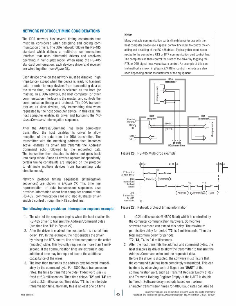
MTS SensorsLevel Plus® Liquid-Level Transmitters M-Series Model MG Digital Transmitter
Operation and Installation Manual, Document Number: 550791 Revision L (KOR) 03/201445
NETWORK PROTOCOL/TIMING CONSIDERATIONS
The DDA network has several timing constraints that must be considered when designing and coding com-munication drivers. The DDA network follows the RS-485 standard which defines a multi-drop communication interface that uses differential drivers and receivers operating in half-duplex mode. When using the RS-485 standard configuration, each device’s driver and receiver are wired together (see Figure 26).
Each device drive on the network must be disabled (high impedance) except when the device is ready to transmit data. In order to keep devices from transmitting data at the same time, one device is selected as the host (or master). In a DDA network, the host computer (or other communication interface) is the master, and controls the communication timing and protocol. The DDA transmit-ters act as slave devices, only transmitting data when requested by the host computer device. In this case, the host computer enables its driver and transmits the ‘Ad-dress/Command’ interrogation sequence.
After the Address/Command has been completely transmitted, the host disables its driver to allow reception of the data from the DDA transmitter. The transmitter with the matching address then becomes active, enables its driver and transmits the Address/Command echo followed by the requested data. The transmitter then disables its driver and goes back into sleep mode. Since all devices operate independently, certain timing constraints are imposed on the protocol to eliminate multiple devices from transmitting data simultaneously.
Network protocol timing sequences (interrogation sequences) are shown in (Figure 27. This time line representation of data transmission sequences also provides information about host computer control of the RS-485 communication card and also illustrates driver enabled control through the RTS control line.
DDA transmitter
Mic
ropr
oces
sor
HostcomputerEnable
controlData
IN
DataOUT
(RX/TX+)
(RX/TX-)
To otherDDA transmitters
DDA transmitter
Mic
ropr
oces
sor
Figure 26. RS-485 Multi-drop example
T1 T5
T2T3
T4
T6 T7T8
T9T10
T12
T11
DataCommandAddress
CommandAddress
T0
RTS controlof host driver
Datatransmitted
by hostdevice
Datatransmitted
by DDAtransmitter
Figure 27. Network protocol timing informationThe following steps provide an interrogation sequence example:
1. The start of the sequence begins when the host enables its RS-485 driver to transmit the Address/Command bytes (see time line ‘T0’ in Figure 27).
2. After the driver is enabled, the host performs a small time delay ‘T1’. In this example, the host enables the driver by raising the RTS control line of the computer to the active (enabled) state. This typically requires no more than 1 milli- second. If the communication lines are extremely long, additional time may be required due to the additional capacitance of the wires.
3. The host then transmits the address byte followed immedi- ately by the command byte. For 4800 Baud transmission rates, the time to transmit one byte (11-bit word size) is fixed at 2.3 milliseconds. Then time delays ‘T2’ and ‘T4’ are fixed at 2.3 milliseconds. Time delay ‘T3’ is the interbyte transmission time. Normally this is at least one bit time
1. (0.21 milliseconds @ 4800 Baud) which is controlled by the computer communication hardware. Sometimes software overhead can extend this delay. The maximum permissible delay for period ‘T3’ is 5 milliseconds. Then the total maximum delay for periods ‘T2, T3, T4’ is 9.6 milliseconds.
2. After the host transmits the address and command bytes, the host disables its driver to allow the transmitter to transmit the Address/Command echo and the requested data. Before the driver is disabled, the software must insure that the command byte has been completely transmitted. This can be done by observing control flags from ‘UART’ of the communication port, such as Transmit Register Empty (TRE) and Transmit Holding Register Empty (if the UART is double buffered). Software delay methods based on maximum character transmission times for 4800 Baud rates can also be
Note:
Many available communication cards (line drivers) for use with the host comput er device use a special control line input to control the en-abling and disabling of the RS-485 driver. Typically this input is con-nected to the computers RTS or DTR communication port control line. The computer can then control the state of the driver by toggling the RTS or DTR signal lines via software control. An example of this con-trol method is shown in (Figure 27). Other control methods are also used depending on the manufacturer of the equipment.

MTS SensorsLevel Plus® Liquid-Level Transmitters M-Series Model MG Digital Transmitter Operation and Installation Manual, Document Number: 550791 Revision L (KOR) 03/2014 46
1. Interrogation sequence examples (Continued) used but are less reliable. Once it has been verified that the command byte ‘0’ has been completely transmitted, an additional delay should be added before the driver is disabled. This delay ‘T5’ will insure that data has propagated the network wiring before the driver goes to the high impedance (disabled) state. A delay period of ‘T5’ = 1 millisecond is adequate for most long cable runs. The maximum delay allowed for ‘T5’ is based on the fact that time period ‘T6’ is fixed in the DDA hardware to be 22 (+/-2) milliseconds. The host driver should be disabled well before (at least 5 milliseconds) the DDA transmitter enables its driver and begins transmission of the Address/Command echo. Assuming the maximum delay of 5 milliseconds for period ‘T3’, and 2.3 milliseconds for ‘T4’, and that the host driver should be disabled for 5 milliseconds before the transmitter begins transmitting data, the maximum delay for ‘T5’ then is 7.7 milliseconds.
Note:
If ‘T3’ is less than 5 milliseconds, then the maximum delay for ‘T5’ can be extended by the difference (5 milliseconds - T3 actual).
2. The transmitter will begin to transmit the Address/Command echo in 22 (+/- 2) milliseconds after the address byte is received from the host computer. This is defined as period ‘T6’ and is fixed by the DDA hardware. Based on a Baud rate of 4800, the address echo is transmitted in 2.3 milliseconds (period ‘T7’). The interbyte delay period ‘T8’ for the DDA transmitter is fixed at 0.1 milliseconds and the command echo is transmitted 2.3 milliseconds (period ‘T9’).
3. Period ‘T10’ is the time required for the DDA electronics to perform the requested command. This is a variable
1. delay based on the command requested. The typical transmitter response time for each command is listed in section ‘11.4 DDA command definitions’.
2. Period ‘T11’ is the time required for the DDA electronics to transmit the data for the requested command. This is a variable delay based on the command requested. The typical data transmission time for each command is listed in section ‘11.4 DDA command definitions’.
3. After the transmitter has completed the data transmission for the requested command, it will disable its driver and go back to inactive mode. The transmitter electronics require 50 milliseconds to transition from active mode to inactive mode. Another transmitter (or the same transmitter) cannot be interrogated until time period ‘T12’ = 50 milli- seconds has elapsed.4. Repeat the sequence for the next transmitter.
Other protocol considerations
1. The transmitted ASCII data from the DDA transmitter may contain data fields with ‘Exxx’ error codes. All DDA error codes are preceded by ASCII ‘E’ (45 hex, 69 decimal). Communica- tion interface drivers must parse and handle DDA error codes properly or data processing errors could result. For additional information about DDA error codes, (see page 54 ).
2. Use the DDA ‘Data Error Detection’ function to verify the integrity of the data transmitted from the transmitter.
3. Certain RS-485 communication cards and (RS-232 to RS-485 converter cards) allow user control of the receiver function. This feature must be considered when developing com- munication drivers. Due to the half-duplex RS-485 loopback wire connections, all data that is transmitted by the host computer device will be ‘echoed’ into the receiver inputs. If the receiver function is enabled, then the host transmitted data along with the DDA transmitter transmitted data will be received into the computer receive buffer.
DDA Command definitions (includes protocol information)
SPECIAL CONTROL COMMANDS
Command 00 Hex (0 Dec) - Transmitter disable command
This command can be used to disable an active transmitter (force transmitter back to sleep mode). This command does not need to be preceded by an address byte and can only be issued when DDA transmitters are not transmitting data. This ‘disabled’ command is typically used with other commands that could leave the transmitter in active mode, i.e. certain memory transfer commands, test mode commands, etc.
Note:
During normal mode operation, a DDA transmitter will force itself back into sleep mode if any data is transmitted on the network by any other device. This is a safety feature added to the firmware to avoid data colli-sions on the network.
Command 01 Hex (1 Dec): Module identification commandData format: <STX><DDA><ETX><ccccc>• Fixed length record containing 3 ASCII characters ‘<DDA>’• Five (5) character checksum appended after ‘<ETX>’ character set
Command 02 Hex (2 Dec): Change addressData format: <SOH><ddd><EOT>
• Fixed length record with three (3) characters• The data field is the new address• The data range is the new address• The data range is from 192 - 253• ‘<SOH>’ is ASCII 01 Hex• ‘<EOT>’ is ASCII 04 Hex• Default Address is ‘192’
Command 03 Hex - Command Hex 09 - Not Defined

MTS SensorsLevel Plus® Liquid-Level Transmitters M-Series Model MG Digital Transmitter
Operation and Installation Manual, Document Number: 550791 Revision L (KOR) 03/201447
LEVEL COMMANDS
Command 0A Hex (10 Dec): Output level 1 (product) at 0.1 inch resolution (with checksum)Data format: <STX><dddd.d><ETX><ccccc>• Variable length record with one (1) to four (4) characters to the left of
decimal character• Fixed at one (1) character to the right of decimal character• Five (5) character checksum appended after the ‘<ETX>’
character set
Note:
<ccccc> Checksum characters are only appended if the Data Error Detection (DED) function is enabled.
Command 0B Hex (11 Dec): Output level 1 (product) at 0.01 inch resolution (with checksum)Data format: <STX><dddd.dd><ETX><ccccc>
• Variable length record with one (1) to four (4) characters to the left of decimal character
• Fixed at two (2) characters to the right of decimal character• Five (5) character checksum appended after the ‘<ETX>’ character set
Command 0C Hex (12 Dec): Output level 1 (product) at 0.001 inch resolution (with checksum) Data format: <STX><dddd.ddd><ETX><ccccc>
• Variable length record with one (1) to four (4) characters to the left of decimal character
• Fixed at three (3) characters to the right of decimal character
• Five (5) character checksum appended after ‘<ETX’> character set
Data characters can include the following:
• 0 through 9 • (-) minus sign • (.) decimal point • (E) ASCII 45 Hex precedes all error codes • (:) ASCII 3A Hex is used as a data field separator for multiple data field transmissions • (space) ASCII 20 Hex space character
Command 0D Hex (13 Dec): Output level 2 (interface) at 0.1 inch resolution (with checksum)Data format: Same as Command 0A
Command 0E Hex (14 Dec): Output level 2 (interface) at 0.01 inch resolution (with checksum)Data format: Same as Command 0B
Command 0F Hex (15 Dec): Output level 2 (interface) at 0.001 inch resolution (with checksum)Data format: Same as Command 0C
Command 10 Hex (16 Dec): Output level 1 (product) and level 2 interface at 0.1 inch resolution (with checksum)Data format: <STX><dddd.d:dddd.d><ETX><ccccc>
• Variable length record with one (1) to four (4) characters to the left of each decimal character in each data field
• Fixed at one (1) character to the right of each decimal character in each
• data field• Level 1, level 2 data fields separated by ASCII colon (:) character• Five (5) character checksum appended after the ‘<ETX>’ character set
Command 11 Hex (17 Dec): Output level 1 (product) and level 2 (interface) at 0.01 inch resolution (with checksum)Data format: <STX><dddd.dd:dddd.dd><ETX><ccccc>
• Variable length record with one (1) to four (4) characters to the left of each decimal character in each data field
• Fixed at two (2) characters to the right of each decimal character in each data field.
• Level 1, level 2 data fields separated by ASCII colon (:) character• Five (5) character checksum appended after the ‘<ETX>’ character set
Command 12 Hex (18 Dec): Output level 1 (product) and level 2 (interface) at 0.001 inch resolution (with checksum)Data format: <STX><dddd.ddd:dddd.ddd><ETX><ccccc>
• Variable length record with one (1) to four (4) characters to the left of each decimal character in each data field
• Fixed at three (3) characters to the right of each decimal character in each data field
• Level 1, level 2 data fields separated by ASCII colon (:) character • Five (5) character checksum appended after the ‘<ETX>’ character set
Command 13 Hex - Command 18 Hex - Not Defined
TEMPERATURE COMMANDS
Command 19 Hex (25 Dec): Average Temperature at 1.0 °F resolution (with checksum)Data format: <STX><dddd><ETX><ccccc>
• Variable length record with one (1) to four (4) characters • Five (5) character checksum appended after the ‘<ETX>’ character set
Note:
Average temperature is the average temperature reading from all DTs sub-merged by approximate ly 1.5 inches of product.
Command 1A Hex (26 Dec): Average temperature at 0.2 °F resolution (with checksum)Data format: <STX><dddd.d><ETX><ccccc>
• Variable length record with one (1) to four (4) characters to the left of decimal character
• Fixed at one (1) character to the right of decimal character • Five (5) character checksum appended after the ‘<ETX>’ character set
Command 1B Hex (27 Dec): Average temperature at 0.02 °F resolution (with checksum)Data format: <STX><dddd.dd><ETX><ccccc>
• Variable length record with one (1) to four (4) characters to the left of decimal character
• Fixed at two (2) characters to the right of decimal character • Five (5) character checksum appended after the ‘<ETX>’ character set

MTS SensorsLevel Plus® Liquid-Level Transmitters M-Series Model MG Digital Transmitter Operation and Installation Manual, Document Number: 550791 Revision L (KOR) 03/2014 48
TEMPERATURE COMMANDS (CONTINUED)
Command 1C Hex (28 Dec): Individual DT temperature at 1.0 °F resolution (with checksum)Data format: <STX><dddd:dddd:dddd:dddd:dddd><ETX><ccccc>
• Variable length record with one (1) to four (4) characters in each data field
• Variable number of data fields (up to 5) separated by ASCII colon (:) characters. Number of data fields is based on the number of DTs programmed in DDA transmitter memory
• First data field is always DT #1, second data field is DT #2, etc • Five (5) character checksum appended after the ‘<ETX>’ character set
Command 1D Hex (29 Dec): Individual DT temperature at 0.2 °F resolution (with checksum)Data format: <STX><dddd.d:dddd.d:dddd.d:dddd.d:dddd.d><ETX><ccccc>
• Variable length record with one (1) to four (4) characters to the left of decimal character in each data field
• Fixed at one (1) character to the right of each decimal character in each data field
• Variable number of data fields (up to 5) separated by ASCII colon (:) characters. Number of data fields is based on the number of DTs programmed in DDA transmitter memory
• First data field is always DT #1, second data field is DT #2,...etc • Five (5) character checksum appended after the ‘<ETX>’ character set
Command 1E Hex (30 Dec): Individual DT temperature at 0.02 °F resolution (with checksum)Data format: <STX><dddd.dd:dddd.dd:dddd.dd:dddd.dd:dddd.dd><ETX><ccccc>
• Variable length record with one (1) to four (4) characters to the left of decimal character in each data field
• Fixed at two (2) characters to the right of each decimal character in each data field
• Variable number of data fields (up to 5) separated by ASCII colon (:) characters. Number of data fields is based on the number of DTs programmed in DDA transmitter memory
• First data field is always DT#1, second data field is DT #2,...etc• Five (5) character checksum appended after the ‘<ETX>’ character set
Command 1F Hex (31 Dec): Average and individual DT temperature at 1.0 °F resolution (with checksum).Data format: <STX><dddd:dddd:dddd:dddd:dddd:dddd><ETX><ccccc>
• Variable length record with one (1) to four (4) characters in each data field
• Variable number of data fields (up to 6) separated by ASCII colon (:) characters. The number of data fields is based on the number of DTs programmed in DDA transmitter memory (number of DTs + 1)
• The first data field is always the average of the individual DTs submerged by at least 1.5 inches of product
• The second data field is always DT #1, third data field is DT #2, ... etc • Five (5) character checksum appended after the ‘<ETX>’ character set
Command 20 Hex (32 Dec): Average and individual DT temperature at 0.2 °F resolution (with checksum).Data format: <STX><dddd.d:dddd.d:dddd.d:dddd.d:dddd.d:dddd.d><ETX><ccccc>• Variable length record with one (1) to four (4) characters to the left of
decimal character in each data field• Fixed at one (1) character to the right of each decimal character in each
data field • Variable number of data fields (up to 6) separated by ASCII colon (:)
characters. The number of data fields is based on the number of DTs programmed in DDA transmitter memory (number of DTs + 1)
• The first data field is always the average of the individual DTs submerged by at least 1.5 inches of product
• The second data field is always DT #1, third data field is DT #2, ... etc • Five (5) character checksum appended after the ‘<ETX>’ character set
Command 21 Hex (33 Dec): Average and individual DT temperature at 0.02 °F resolution (with checksum).Data format: <STX><dddd.dd:dddd.dd:dddd.dd:dddd.dd:dddd.dd:dddd.dd><ETX><ccccc>
• Variable length record with one (1) to four (4) characters to the left of decimal character in each data field
• Fixed at two (2) characters to the right of each decimal character in each data field
• Variable number of data fields (up to 6) separated by ASCII colon (:) characters. The number of data fields is based on the number of DTs programmed in DDA transmitter memory (number of DTs + 1)
• The first data field is always the average of the individual DTs submerged by at least 1.5 inches of product
• The second data field is always DT #1, third data field is DT #2, ... etc• Five (5) character checksum appended after the ‘<ETX>’ character set
Command 22 Hex - Command 24 Hex - ReservedCommand 25 Hex (37 Dec): Fast average and individual DT temperature at 1.0 °F resolution (with checksum)Data format: Same as command 1F Hex
Command 26 Hex - Command 27 Hex - Not defined
MULTIPLE OUTPUT COMMANDS (LEVEL AND TEMPERATURE)
Command 28 Hex (40 Dec): Level 1 (product) at 0.1 inch resolution, and average temperature at 1.0 °F resolution (with checksum) Data format: <STX><dddd.d:dddd><ETX><ccccc> • Variable length record with one (1) to four (4) characters to the left of
decimal character in first data field• Fixed at one (1) character to the right of decimal character in first data
field• Variable length record with one (1) to four (4) characters in second data
field• Level 1 temperature data fields separated by ASCII colon (:) character • Five (5) character checksum appended after the ‘<ETX>’ character set

MTS SensorsLevel Plus® Liquid-Level Transmitters M-Series Model MG Digital Transmitter
Operation and Installation Manual, Document Number: 550791 Revision L (KOR) 03/201449
MULTIPLE OUTPUT COMMANDS (CONTINUED)
Command 29 Hex (41 Dec): Level 1 (product) at 0.01 inch resolution, and average temperature at 0.2 °F resolution (with checksum)Data format: <STX><dddd.dd:dddd.d><ETX><ccccc> • Variable length record with one (1) to four (4) characters to the left of
decimal character in first data field• Fixed at two (2) characters to the right of decimal character in first data
field• Variable length record with one (1) to four (4) characters to the left of
decimal character in second data field • Fixed at one (1) character to the right of decimal character in second
data field. • Level 1, temperature data fields separated by ASCII colon (:) character. • Five (5) character checksum appended after the ‘<ETX>’ character set
Command 2A Hex (42 Dec): Level 1 (product) at 0.001 inch resolution, and average temperature at 0.02 °F resolution (with checksum)Data format: <STX><dddd.ddd:dddd.dd><ETX><ccccc>
• Variable length record with one (1) to four (4) characters to the left of decimal character in first data field
• Fixed at three (3) characters to the right of decimal character in first data field
• Variable length record with one (1) to four (4) characters to the left of decimal character in second data field
• Fixed at two (2) characters to the right of decimal character in second data field
• Level 1, temperature data fields separated by ASCII colon (:) character • Five (5) character checksum appended after the ‘<ETX>’ character set
Command 2B Hex (43 Dec): Level 1 (product), level 2 (interface) at 0.1 inch resolution, and average temperature at 1.0 °F resolution (with checksum)Data format: <STX><dddd.d:dddd.d:dddd><ETX><ccccc>
• Variable length record with one (1) to four (4) characters to the left of decimal character in first data field
• Fixed at one (1) character to the right of decimal character in first data field
• Variable length record with one (1) to four (4) characters to the left of decimal character in second data field
• Fixed at one (1) character to the right of decimal character in second data field
• Variable length record with one (1) to four (4) characters in third data field
• Level 1, level 2, temperature data fields separated by ASCII colon (:) character
• Five (5) character checksum appended after the ‘<ETX>’ character set
Command 2C Hex (44 Dec): Level 1 (product), level 2 (interface) at 0.01 inch resolution, and average temperature at 0.2 °F resolution (with checksum)Data format: <STX><dddd.dd:dddd.dd:dddd.d><ETX><ccccc>
• Variable length record with one (1) to four (4) characters to the left of
• decimal character in first data field• Fixed at two (2) characters to the right of decimal character in first data
field• Variable length record with one (1) to four (4) characters to the left of
decimal character in second data field • Fixed at two (2) characters to the right of decimal character in second
data field • Variable length record with one (1) to four (4) characters to the left of
decimal character in third data field. • Fixed at one (1) character to the right of decimal character in third data
field• Level 1, level 2, temperature data fields separated by ASCII colon (:)
character • Five (5) character checksum appended after the ‘<ETX>’ character set
Command 2D Hex (45 Dec): Level 1 (product), level 2 (interface) at 0.001 inch resolution, and average temperature at 0.02 °F resolution (with checksum)Data format: <STX><dddd.ddd:dddd.ddd:dddd.dd><ETX><ccccc>
• Variable length record with one (1) to four (4) characters to the left of decimal character in first data field.
• Fixed at three (3) characters to the right of decimal character in first data field.
• Variable length record with one (1) to four (4) characters to the left of decimal character in second data field.
• Fixed at three (3) characters to the right of decimal character in second data field.
• Variable length record with one (1) to four (4) characters to the left of decimal character in third data field.
• Fixed at two (2) characters to the right of the decimal character in third data field.
• Level 1, level 2, temperature data fields separated by ASCII colon (:) char acter.
• Five (5) character checksum appended after the ‘<ETX>’ character set
Command 2E Hex - Command 30 Hex - Not Defined Command 31 Hex - Command 40 Hex - Reserved for factory use
HIGH-LEVEL MEMORY READ COMMANDS
Command 4B Hex (75 Dec): Read ‘number of floats and number of DTs’ control variablesData format: <STX><d:d><ETX><ccccc>
• Fixed length record with one (1) character in each field. • The first data field is the number of floats, second data field is the
number of DTs• Five (5) character checksum appended after the ‘<ETX>’ character set
Command 4C Hex (76 Dec): Read ‘gradient’ control variableData format: <STX><d.ddddd><ETX><ccccc>
• Fixed length record with seven (7) characters (including decimal point).• Five (5) character checksum appended after the ‘<ETX>’ character set
Command 4D Hex (77 Dec): Read float zero position data (float #1 and #2)Data format: <STX><dddd.ddd:dddd.ddd><ETX><ccccc> (Continued on next page)

MTS SensorsLevel Plus® Liquid-Level Transmitters M-Series Model MG Digital Transmitter Operation and Installation Manual, Document Number: 550791 Revision L (KOR) 03/2014 50
HIGH-LEVEL MEMORY READ COMMANDS (CONTINUED)
Command 4D Hex (77 Dec): continued
• Variable length record with one (1) to four (4) characters to the left of dec imal character in first data field. The data may include an ASCII (-) negative sign character (2D Hex) in the first character position
• Fixed at three (3) characters to the right of decimal character in first data field
• Variable length record with one (1) to four (4) characters to the left of decimal character in second data field. The data may include an ASCII(-) negative sign character (2D Hex) in the first character position
• Fixed at three (3) characters to the right of decimal character in second data field
• Float #1, float #2 data fields separated by ASCII colon (:) character• Five (5) character checksum appended after the ‘<ETX>’ character set
Command 4E Hex (78 Dec): Read DT position data (DTs 1 - 5)Data format: <STX><dddd.d:dddd.d:dddd.d:dddd.d:dddd.d><ETX><ccccc>
• Variable length record with one (1) to four (4) characters to the left of decimal character in each data field
• Fixed at one (1) character to the right of decimal character in each data field
• Variable number of data fields (up to 5) separated by ASCII colon (:) characters. The number of data fields is based on the ‘number of DTs’ control variable. (see command 4B Hex)
• The first data field is always DT #1, second field is always DT #2,...etc.• Five (5) character checksum appended after the ‘<ETX>’ character set
Note:
DT position data is referenced from the mounting flange of the transmitter housing. DT #1 is the DT closest to the tip of the transmitter.
Command 4F Hex (79 Dec): Read factory serial number data and software version numberData format: <STX><ddddd....ddddd:Vd.ddd><ETX><ccccc>• Fixed length record of 50 characters to the left of the colon character
and 6 characters to the right of the colon character (57 total)• Five character checksum appended after the ‘<ETX>’ character set
Command 50 Hex (80 Dec): Read firmware control code #1Data format: <STX><d:d:d:d:d:d><ETX><ccccc>
• Fixed length record with one (1) character in each data field• First data field is the control variable for the data error detection (DED)
mode • The second data field is the control variable for the communication
time-out timer (CTT)• The third data field is the control variable for temperature data units • The fourth data field is the control variable for linearization enable/
disable• The fifth data field is the control variable for innage/ullage level output• The sixth data field is reserved for future use; the output value for this
• field is ASCII ‘0’ • See write command (5A Hex) for field value assignments • Five (5) character checksum appended after the ‘<ETX>’ character set
Command 51 Hex (81 Dec): Read hardware control code #1Data format: <STX><dddddd><ETX><ccccc>
• Fixed length record with six (6) characters • The hardware control code controls various functions in the DDA
electronic hardware• The hardware control code must match the hardware control code
stamped on the transmitter label; the control code on the label is preceded by ‘CC’ (for example, CC001122)
• Five (5) character checksum appended after the ‘<ETX>’ character set • For additional information about the hard ware control code, (see section
8, Quick Start-up Guide Modbus and DDA)
Command 52 Hex (82 Dec): Not defined
Command 53 Hex (83 Dec): Reserved for factory use
Command 54 Hex (84 Dec): Not defined
HIGH-LEVEL MEMORY WRITE COMMANDS
Command 55 Hex (85 Dec): Write ‘number of floats and number of DTs’ control variablesHost Issued Command (Part 1)Data format: <addr><commands> • ‘<addr>’ is the DDA transmitter address • ‘<command>’ is DDA command 55 • After the address and command byte have been transmitted by the host,
the respective DDA transmitter will ‘wake up’ and retransmit (echo) the local DDA address and received command. The DDA transmitter will remain active, waiting for the second part of the memory write command to be issued by the host. If the second part of the memory write command is not received within 1.0 seconds (see note below), or the command is not received in the proper format, the DDA transmitter will cancel the current command sequence and go back to sleep mode.
Note:
The time-out timer function can be enabled or disabled.
Host Issued Command (Part 2)
Data format: <SOH><d:d><EOT>
• Fixed length record with two (2) data fields• ‘<SOH>’ is ASCII 01 Hex• The first data field contains the ‘number of floats’ value to be written to
the ‘number of floats’ control variable. This variable is limited to a value of 1 or 2 (ASCII)
• The second data field contains the ‘number of DTs’ value to be written to the ‘number of DTs’ control variable. This variable is limited to a value between 0 and 5 (ASCII)
• ASCII colon (:) is the ‘number of floats/number of DTs’ field separator.• ‘<EOT>’ is ASCII 04 Hex
DDA Transmitter Response (verification sequence)Data format: <STX><d:d><ETX><ccccc>
MTS SensorsLevel Plus® Liquid-Level Transmitters M-Series Model MG Digital Transmitter
Operation and Installation Manual, Document Number: 550791 Revision L (KOR) 03/201451
HIGH-LEVEL MEMORY WRITE COMMANDS (CONTINUED)
• Fixed length record with two (2) data fields• ‘<STX>’ is ASCII 02 Hex• The first data field contains the ‘number of floats’ value to be written to
the ‘number of floats’ control variable. This variable is limited to a value of 1 or 2 (ASCII)
• The second data field contains the ‘number of DTs’ value to be written to the ‘number of DTs’ control variable. This variable is limited to a value between 0 and 5 (ASCII)
• ASCII colon (:) is the ‘number of floats/number of DTs’ field separator• ‘<ETX>’ is ASCII 03 Hex• ‘<ccccc>’ is a five (5) character checksum appended after the ‘<ETX>’
character set
Host Issued Command (Part 3)Data format: <ENQ>
• ‘<ENQ>’ is ASCII 05 Hex. This character set is sent by the host to initiate the EEPROM write cycle. After the EEPROM memory locations have been successfully written to, the DDA transmitter will respond back to the host with a ‘ACK’ character set signifying the memory write cycle was successful, or with a ‘NAK’ character signifying the memory write cycle was unsuccessful. See DDA transmitter response below.
• EEPROM write time is 10 milliseconds per byte. The ‘ACK/NAK’ response will not be transmitted by the DDA transmitter until the memory bytes have been written and verified or a memory write error has caused the DDA transmitter to time-out.
Note:
EEPROM write time is 10 milliseconds per byte. The ACK/NAK response will not be transmitted by the DDA transmitter until the memory bytes have been written and verified or a memory write error has caused the DDA transmitter to time-out.
DDA Transmitter Response:Data format: <ACK>
• ‘<ACK>’ is ASCII 06 Hex. This character set is sent by the DDA transmitter to confirm to the host that the EEPROM memory write cycle was completed successfully.
Data format: <NAK><Exxx><ETX><ccccc>
• ‘<NAK>’ is ASCII 15 Hex. This character set is sent by the DDA transmitter to confirm to the host that the EEPROM memory write cycle was not completed successfully.
• ‘<Exxx>’ is an error code defining the memory write error that occurred during the EEPROM write cycle. ‘E’ is ASCII 45 Hex and ‘xxx’ is the numeric ASCII error code ranging from 000 to 999. For additional information about DDA error codes, (see section X.X).
• ‘<ETX>’ is ASCII 03 Hex • ‘<ccccc>’ is a five character checksum appended after the ‘<ETX>’
character set• Value can range from 00000 to 65535.
All high level memory write commands adhere to the communication se-quence as described above, and consist of the following six components:
1. Host issued command (Part 1): <address><command> 2. DDA transmitter response: <address><command> echo 3. Host issued command (Part 2):
data to be written (including necessary control characters) 4. DDA transmitter response: verification sequence 5. Host issued command (Part 3): <ENQ> 6. DDA transmitter response: <ACK> or <NAK>
Descriptions for other high level memory write commands will include only the Data format for Part 2 of each host issued command.
Command 56 Hex (86 Dec): Write ‘gradient’ control variableData format: <SOH><d.ddddd><EOT>• Fixed length record with one data field• ‘<SOH>’ is ASCII 01 Hex• The fixed length data field contains the ‘gradient’ value to be written to
the ‘gradient’ control variable. This variable is limited to a value between 7.00000 and 9.99999 (ASCII)
• ‘<EOT>’ is ASCII 04 Hex
Command 57 Hex (87 Dec): Write float zero position data (float #1 or #2)Data format: <SOH><c:dddd.ddd><EOT>
• Variable length record with two (2) data fields• The first data field contains one character that controls which zero
position memory location is written to (i.e., float #1 or float #2). This control character is limited to a value of 1 or 2 (ASCII)
• The second data field contains the ‘zero position’ data value to be written to the ‘zero position’ memory location. This is a variable length data field with one (1) to four (4) characters to the left of the decimal character and fixed at three (3) characters to the right of the decimal character. The data may include the ASCII (-) negative sign character (2D Hex) in the first position. The zero position data is limited to a value between -999.999 and 9999.999 (ASCII)
• ‘<EOT>’ is ASCII 04 Hex
Note:
Zero position is referenced from the mounting flange of the transmitter housing.
Command 58 Hex (88 Dec): Write float zero position data (float #1 or #2) using DDA calibrate mode.Data format: <SOH><c:dddd.ddd><EOT>
• Variable length record with two (2) data fields• The first data field contains one character that controls which zero
position memory location is written to (i.e., float #1 or float #2). This control character is limited to a value of 1 or 2 (ASCII)
• The second data field contains the ‘current float position’ data value to be used to calculate the ‘zero position’ value that is to be written to the ‘zero position’ memory location. This is a variable length data field with one (1) to four (4) characters to the left of the decimal character and fixed at three (3) characters to the right of the decimal character. The data may include the ASCII (-) negative sign character (2D Hex) in the first position. The ‘current float position’ data is limited to a value between -999.999 and 9999.999 (ASCII)
• ‘<EOT>’ is ASCII 04 Hex

MTS SensorsLevel Plus® Liquid-Level Transmitters M-Series Model MG Digital Transmitter Operation and Installation Manual, Document Number: 550791 Revision L (KOR) 03/2014 52
HIGH-LEVEL MEMORY WRITE COMMANDS (CONTINUED)
Command 59 Hex (89 Dec): Write DT position data (DT1-5).Data format: <SOH><c:dddd.d><EOT• Variable length record with two (2) data fields • The first data field contains one (1) character that controls which ‘DT
position’ memory location is written to (i.e. DT position #1, 2, 3, 4 or 5)• This control character is limited to a value between 1 and 5 (ASCII) • The second data field contains the ‘DT position’ data value to be written
to the respective ‘DT position’ memory location. This is a variable length data field with one (1) to four (4) characters to the left of the decimal character and fixed at one (1) character to the right of the decimal character. The DT position data is limited to a value between 0.0 and 9999.9 (ASCII)
• ‘<EOT>’ is ASCII 04 Hex
Command 5A Hex (90 Dec): Write firmware control code #1Data format: <SOH><d:d:d:d:d:d><EOT>
• Fixed length record with one character in each data field • ‘<SOH>’ is ASCII 01 Hex • The first data field is the control variable for the data error detection
(DED) function. This variable can have a value of 0, 1, or 2. A value of 0 enables the DED function, using a 16-bit checksum calculation. A value of 1 enables the DED function, using a 16-bit CRC calculation. A value of 2 disables the DED function
• The second field is the control variable for the communication time-out timer (CTT) function. This variable can have a value of 0 or 1. A value of 0 enables the CTT function, and a value of 1 disables the CTT function
• The third data field is the control variable for temperature data units This variable can have a value of 0 or 1. A value of 0 enables Fahrenheit temp erature units. A value of 1 enables Celsius temperature units
• The fourth data field is the control variable for linearization control. This variable can have a value of 0 or 1. A value of 0 disables linearization of the level data. A value of 1 enables linearization
• The fifth data field is the control variable for innage/ullage level output. This variable can have a value of 0,1 or 2. A value of 0 enables normal innage level output. A value of 1 enables ullage level output and a value of 2 enables ullage level output with reversed DT submersion processing. Mode 2 is used for inverted transmitter applications where the transmitter is installed from the bottom of the tank
• The sixth data field is reserved for future use. The data value for this field must be ‘0’ (ASCII 30 Hex)
• ‘<EOT>’ is ASCII 04 Hex
Command 5B Hex (91 Dec): Write hardware control code #1Data format: <SOH><dddddd><EOT>
• Fixed length record with six (6) characters• ‘<SOH>’ is ASCII 01 Hex • The hardware control code controls various functions in the DDA
electronic hardware • The hardware control code must match the hardware control code
stamped on the transmitter label. The control code on the label is preceded by ‘CC’ (i.e. CC001122)
• ‘<EOT>’ is ASCII 04 Hex
Command 5C Hex (92 Dec): Not Defined
Command 5D Hex (93 Dec): Reserved for factory use
Command 5F Hex - 7F Hex - Reserved for future use
DIAGNOSTIC/SPECIAL COMMAND SET
enum alarmStatusBitsINTERFACE_ALARM_HIGH = 0x0001INTERFACE_ALARM_LOW = 0x0002PRODUCT_ALARM_HIGH = 0x0004PRODUCT_ALARM_LOW = 0x0008ROOF_ALARM_HIGH = 0x0010ROOF_ALARM_LOW = 0x0020AVG_TEMP_ALARM_HIGH = 0x0040AVG_TEMP_ALARM_LOW = 0x0080MAGNET_IS_MISSING = 0x0100DIG_TEMP0_ERROR = 0x0200DIG_TEMP1_ERROR = 0x0400DIG_TEMP2_ERROR = 0x0800DIG_TEMP3_ERROR = 0x1000DIG_TEMP7_ERROR = 0x2000DIG_AVG_TEMP_ERROR = 0x4000DELIVERY_IN_PROGRESS = 0x8000TRIGGER_LEVEL_ERROR = 0x10000EEPROM_ERROR = 0x20000
DDA ERROR CODES
All error codes are preceded by a capital letter ‘E’ ASCII (45 hex) and are in the form of ‘Exxx’ where ‘xxx’ can be any number from
‘000’ to ‘999’. Error codes can be embedded in any data field within a transmitted record. Certain DDA commands can generate multiple error codes. Refer to the following examples:
Command 0A Hex: <STX><Exxx><ETX><ccccc>
Command 2D Hex: <STX><Exxx:Exxx:ddd.dd><ETX><ccccc>
Command 1E Hex: <STX><E203:dddd.dd:dddd.dd:E207:dddd.dd><ETX><ccccc>
E102: Missing Float(s) (Level 1 or Level 2)The number of floats measured by the hardware is less than the ‘number of floats’ control variable.
E201: No DTs ProgrammedA request for temperature data has been made with the ‘number of DTs’ control variable set to equal zero (0) or all programmed DTs are set inactive (for example, DT position data is set equal to zero (0.000)).
E212: DT Communication ErrorThe indicated DT is not active (for example, DT position data is set equal to zero (0) or is not responding).

MTS SensorsLevel Plus® Liquid-Level Transmitters M-Series Model MG Digital Transmitter
Operation and Installation Manual, Document Number: 550791 Revision L (KOR) 03/201453
Model MG Digital setup software installation, setup and calibration
Adjustments to the calibration and set up parameters of the transmitter can be performed using the M-Series Digital Setup Software package. The software can be run from any PC using a RS-485 to RS-232 converter (see Table 10 MTS part number references). In the ‘MTS Digital Gauge Configuration - DDA -COM’ window, you will see one tab labeled ‘Data From Device’ (see Figure 28). You will use this tab and its but-ton selections to calibrate the transmitter and change setup parameters.
Note:
You must use a RS-485 converter with ‘Send Data Control’ when using the M-Series Digital Setup software to ensure proper operation. Example: B & B Electronics 485BAT3 (815-433-5100 www.bb-elec.com).
Level Plus M-Series PC Digital Setup Software (DDA) CD RS-485 to RS-232 converter
Order number: 625053 Order number: 380075
Table 10. MTS part number references
DATA FROM DEVICE TAB
Perform the following steps to install the transmitter setup software to establish communications with the transmitter:
1. Install Setup Software from the CD that came with your transmitter or go to www.mtssensors.com to download the latest version.
2. Connect transmitter to the RS-485 to RS-232 converter and attach the converter to your PC. Some PC’s will require an additional Serial to USB converter.
3. Open the Software program.4. Select COM Port. If you do not know which COM port to
select, right click My Computer and select Properties -> Hardware Tab -> Device Manager -> Ports (COM & LPT) to view the list.
5. Click the ‘Data From Device’ tab, click the Device: pull-down and select the ‘transmitter address’, the factory default for DDA is 192 (see Figure 28).
Parameter settings and calibration is performed from within the Data From Device tab window (see Figure 28).
DATA FROM DEVICE tab options: • Calibrate • Change Address • COM port • Adjust settings • Backup and restore device settings
Figure 28. Data from device tab
CALIBRATION
When you click the ‘Calibrate’ button in the ‘Data From Device’ tab window, the ‘Calibrate DDA Device’ window opens. There are two calibration ‘Float Methods’ to choose from, ‘Enter Float Positions (Calibrate)’ and ‘Enter Float Zero Positions’. Click the ‘Offset Method:’ drop down menu to select a calibration method. Type a value in the active field, then click the ‘Send’ button. A confirmation window displays when the send is successful.
Figure 29. Calibrate DDA Device window - Offset Method
When you choose ‘Enter Float Zero Positions’ from the ‘Offset Method:’ drop down menu, you can adjust the offset where the transmitters zero point is located. This adjustment will significantly shorten the span of the transmitter or counter inactive zones. Adjust the value accordingly and click ‘Send’. A confirmation window displays when the send is successful.
Figure 30. Calibrate DDA Device - Offset Method

MTS SensorsLevel Plus® Liquid-Level Transmitters M-Series Model MG Digital Transmitter Operation and Installation Manual, Document Number: 550791 Revision L (KOR) 03/2014
CHANGE ADDRESS
To change the transmitter address, click the ‘Change Address’ but-ton in the ‘Data From Device’ tab window. In the ‘Change Address’ window, type the ‘New Address’ in the active field and click ‘Change’. A popup window confirms the change is successful.
Figure 31. Change Address window - New Address entry
BACKUP AND RESTORE DEVICE SETTINGS
If your electronics requires a replacement or if your current settings need to be refreshed, it is recommended that you create a backup or restoration file. To create a backup, click the ‘Backup/Restore’ button in the ‘Data From Device’ tab window . In the ‘Backup and Restore Device Settings” window, click the ‘Get Data From Sensor’ button and ‘Save Settings to File’ button. When prompted, save the file to a designated place where you can find it.
To upload a file, click the ‘Read Settings from File’ button and select your backup file. Click ‘Write Data to Sensor’. A popup window confirms the upload is successful.
Figure 32. Backup and Restore Device Settings window
Adjust settings
To adjust settings, click the ‘Adjust’ button located in the ‘Data From Device’ tab window (see Figure 28). The ‘Adjust DDA Gain’ window displays different parameter settings. All transmitters will have the
ability to adjust the ‘Gain, SARA Blanking and Magnet blanking’ from this menu. These parameters are password protected, changes will require assistance from MTS Technical Support .
Figure 33. Adjust DDA Gain window
COM PORT
To select the Setup Software communication port, click the ‘COM Port’ button in the ‘Data From Device’ tab window. Select the appropriate communication port and click ‘OK’.
Figure 34. Select a COM Port window
CONTINUOUS UPDATE
To view realtime data using the Setup Software interface, select the ‘Continuous Update’ box. The Interval may be changed to slow down updates but is not necessary.
DATA LOGGING
To download a transmitter data log, Click ‘Select File’ in the ‘Data From Device’ tab window. Select an Excel file and check the ‘Log Data to File’ box to save your data.
54
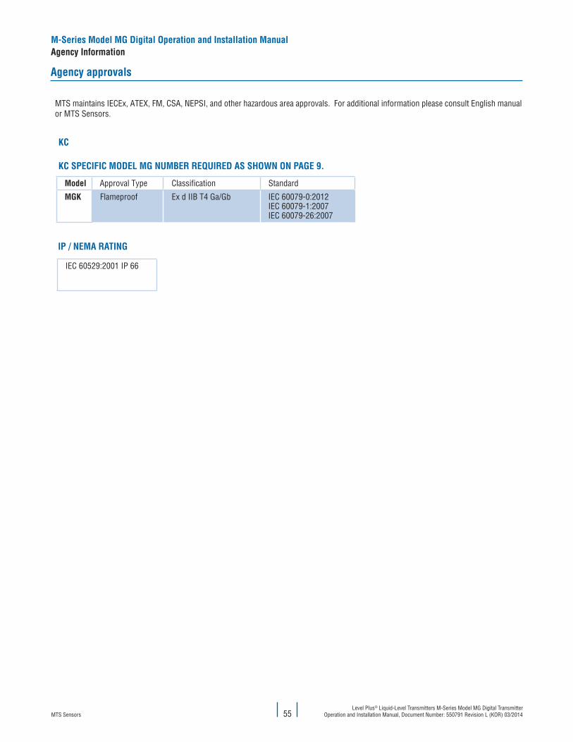
MTS SensorsLevel Plus® Liquid-Level Transmitters M-Series Model MG Digital Transmitter
Operation and Installation Manual, Document Number: 550791 Revision L (KOR) 03/2014
Agency approvals
55
M-Series Model MG Digital Operation and Installation ManualAgency Information
Model Approval Type Classification Standard
MGK Flameproof Ex d IIB T4 Ga/Gb IEC 60079-0:2012IEC 60079-1:2007IEC 60079-26:2007
KC
KC SPECIFIC MODEL MG NUMBER REQUIRED AS SHOWN ON PAGE 9.
IEC 60529:2001 IP 66
IP / NEMA RATING
MTS maintains IECEx, ATEX, FM, CSA, NEPSI, and other hazardous area approvals. For additional information please consult English manual or MTS Sensors.

MTS SensorsLevel Plus® Liquid-Level Transmitters M-Series Model MG Digital Transmitter Operation and Installation Manual, Document Number: 550791 Revision L (KOR) 03/2014 56
Model MG Operation and Installation ManualAgency Information, KC for Modbus and DDA
KC for Modbus and DDA
0.22 mm2 OR HEAVIERTWISTED PAIR CABLEWITH SHIELD
0.22 mm2 OR HEAVIERTWISTED PAIR CABLEWITH SHIELD
RX/T
X−
RX/T
X+
24 V
dc C
OMM
ON
+24
Vdc
TRAN
S. P
ROT.
SEE DETAIL A
TANKSIDEEARTH
GROUND
DETAIL A
NEMA 4X VERSIONEX VERSION
MG _ _ BMG _ _ C
HAZARDOUS LOCATION (Ex d IIB T4 Ga/Gb)
24-26 Vdc +
COMMON −
EARTH GROUND
RX/TX +
RX/TX−
EARTH GROUND
GROUND
NON HAZARDOUSAREA
NON HAZARDOUSLOCATION
Figure 43. KC for Modbus and DDA installation drawing

MTS SensorsLevel Plus® Liquid-Level Transmitters M-Series Model MG Digital Transmitter
Operation and Installation Manual, Document Number: 550791 Revision L (KOR) 03/201457
KC for Modbus and DDA
INSTALLATION DRAWING NOTES
Notes:
1. Power supply cable must be 0,22 mm2 or heavier (e.g. 1.32 mm2 AWG 16), shielded twisted pair cable. Cable capacitance must be less than 90 pF/m (30 pF/ft). Cable shield is connected to system ground at safety barrier end only.
2. Communications cable must be 0.22 mm2 or heavier (e.g. 1.32 mm2 AWG 16), shielded twisted pair cable. Cable capacitance must be less than 90 pF/m (30 pF/ft). Cable shield is connected to system ground at safety barrier end only.
3. The wire connection between earth ground and the safety barrier ground terminal must be less than 1 ohm.4. Connection to earth ground for transient protection circuitry. 5. Ground screw earthing hardware provided to connect gauge housing to earth ground. 6. The transducer frame shall be grounded to earth ground directly or through the equipment on which it is mounted and shall be at
the same potential as the safety barrier ground electrode. 7. Electronic equipment connected to associated apparatus must not use or generate more than 250 volts RMS.8. Cable sets that are run together must have sufficient insulation to withstand 250 volts RMS between sets.9. All wiring must meet the local regulations and/or other national/international standards.10. Seal all conduits within 457 mm (18 in).
Figure 43a. KC for Modbus and DDA installation drawing (continued)
Model MG Operation and Installation ManualAgency Information, KC for Modbus and DDA

MTS SensorsLevel Plus® Liquid-Level Transmitters M-Series Model MG Digital Transmitter Operation and Installation Manual, Document Number: 550791 Revision L (KOR) 03/2014 58
Model MG Operation and Installation ManualAgency Information, KC for Modbus and DDA
Model Number
Approval Agency ApprovalType Approval classifications Ground Connection(Figure reference)
Modbus/DDA
KTL (KC) Flameproof
MGK _ B X X Ex d IIB T4 Ga/Gb Figure 45
MGK _ C X X Ex d IIB T4 Ga/Gb Figure 46
Figure 43b KC for Modbus and DDA installation drawing (continued)
INSTALLATION DRAWING NOTES (CONTINUED)

MTS SensorsLevel Plus® Liquid-Level Transmitters M-Series Model MG Digital Transmitter
Operation and Installation Manual, Document Number: 550791 Revision L (KOR) 03/201459
Model MG Operation and Installation ManualAgency Information, KC for Modbus and DDA
Figure 45. Single cavity housing
Note:
Ground terminal provided in housing to connect gauge housing to earth ground.
Figure 46. Dual cavity housing
WIRING AND CONNECTIONS
RX TX −RX TX +
EARTH
GND
0 Vdc PWR24 Vdc PWR
Ground terminal
Ground terminal
RX T
X −
RX T
X +
EART
H0V 24
V

MTS SensorsLevel Plus® Liquid-Level Transmitters M-Series Model MG Digital Transmitter Operation and Installation Manual, Document Number: 550791 Revision L (KOR) 03/2014
Figure 49. Label for models MG _ _ B and C with industrial rigid pipe
Figure 50. Label for models MG _ _ B and C with flexible hose
Model MG Operation and Installation ManualAgency Information, KC for Modbus and DDA
60
PRODUCT LABELS

MTS SensorsLevel Plus® Liquid-Level Transmitters M-Series Model MG Digital Transmitter
Operation and Installation Manual, Document Number: 550791 Revision L (KOR) 03/2014
SPECIAL CONDITIONS FOR USE
• The electronics housing is to be installed in zone 1 (category 2G, EPL Gb. The sensor pipe/hose may be installed in zone 0 (category 1, EPL Ga if not restricted below.
• Equipotential bonding shall be installed inside and outside the hazardous area along the cable for supply and data.• Float usage:
- Metallic floats may only be used if they have a weight offset (asymmetric weight distribution). - Metallic floats on non-metallic pipes may not be used. - Aluminum floats may not be used.
• Plastic floats may only be installed in hazardous areas which require apparatus of category 1G (for zone 0 with explosion group IIA. Plastic floats may not be used on non-metallic pipes.
• Sensors with flexible measuring hoses: - The hose has to be mechanically protected from external impacts which may affect its function as separation wall. - Avoid kinking or bending the flexible hose in less than 16 inch (406 mm) diameter.
• Consult MTS if dimensional information on flameproof joints are necessary.
Model MG Operation and Installation ManualSpecial Conditions, KC for Modbus and DDA
61

MTS SensorsLevel Plus® Liquid-Level Transmitters M-Series Model MG Digital Transmitter Operation and Installation Manual, Document Number: 550791 Revision L (KOR) 03/2014
Model MG Operation and Installation ManualAgency Information, KC for FOUNDATION™ fieldbus
62
KC installation drawings for FOUNDATIONTM fieldbus
BUS
-
BUS
+
BUS
-
BUS
+
BUS
-
BUS
+
Any FF field device.
Chas
sis
grou
nd
Tankside earthGND
Chas
sis
grou
nd
See Detail A
Tankside earthGND
Detail A
EX Version
MG _ F BMG _ F C
ApprovedTerminator
R= 90 Ω − 100 Ω
C
C= 0−2. 2 µF
R
H1 FIELDBUS SEGMENT
Non-hazardousarea
Earth ground
S
BUS -
9−32 V BUS +
Host linkingDevice
AGENCY CONTROLLED DRAWING REFERENCE.PENDING
HAZARDOUS LOCATION Ex d IIB T4 Ga/Gb
Figure 57. FOUNDATION™ fieldbus installation drawing

MTS SensorsLevel Plus® Liquid-Level Transmitters M-Series Model MG Digital Transmitter
Operation and Installation Manual, Document Number: 550791 Revision L (KOR) 03/201463
Model MG Operation and Installation ManualAgency Information, KC for FOUNDATION™ fieldbus
INSTALLATION DRAWING NOTES
Notes:
1. Cabling shall be FOUNDATIONTM fieldbus H1 Type Cable.2. A terminator is required at each end of a fieldbus between fieldbus network segments.3. Shield is connected to earth ground at one point only, usually at the control room fieldbus power conditioner.4. Ground lug provided to connect gauge housing to earth ground. The transducer frame shall be founded directly or through the
equipment on which it is mounted.5. Electronic equipment connected to associated apparatus must not use or generate more than 250 volts RMS6. Cable sets that are run together must have sufficient insulation to withstand 250 volts RMS between sets.7. Wiring shall be installed in accordance with the country in use (eg Canadian Electrical Code, Part 1, National Electric Code ANS/RFPA
70 Article 504-30).8. Conduit seals are required within 457 mm (18 in.) of housing.9. Caution: In hazardous locations, keep cover tight while circuits are energized.
Figure 57a. installation drawing notes for FOUNDATIONTM fieldbus
Model numberFOUNDATIONTM fieldbus
Approval agencies
Approval types
Approval classificationsGround connection(Figure references)
KTL(KC) Flameproof
MGKFB X X Ex ia IIB T4 Ga/Gb Figure 58
MGKFC X X Ex ia IIB T4 Ga/Gb Figure 59
Figure 57b. FOUNDATIONTM fieldbus installation drawing (continued)

MTS SensorsLevel Plus® Liquid-Level Transmitters M-Series Model MG Digital Transmitter Operation and Installation Manual, Document Number: 550791 Revision L (KOR) 03/2014
64
Model MG Operation and Installation ManualAgency Information, KC for FOUNDATION™ fieldbus
Figure 45. Single cavity housing
Note:
Ground terminal provided in housing to connect gauge housing to earth ground.
Figure 46. Dual cavity housing
WIRING AND CONNECTIONS
BUS
−
BUS
+
BUS+BUS−
Ground screw
Ground screw
GND
Bus -
Bus +

MTS SensorsLevel Plus® Liquid-Level Transmitters M-Series Model MG Digital Transmitter
Operation and Installation Manual, Document Number: 550791 Revision L (KOR) 03/201465
Model MG Operation and Installation ManualAgency Information, KC for FOUNDATION™ fieldbus
Figure 60. Label for models MGKFB and MGKFC with industrial rigid pipe
Figure 61. Label for models MGKFB and MGKFC with flexible hose
PRODUCT LABELS

MTS SensorsLevel Plus® Liquid-Level Transmitters M-Series Model MG Digital Transmitter Operation and Installation Manual, Document Number: 550791 Revision L (KOR) 03/2014
SPECIAL CONDITIONS FOR USE• The electronics housing is to be installed in zone 1 (category 2G, EPL Gb. The sensor pipe/hose may be installed in zone 0
(category 1, EPL Ga if not restricted below.• Equipotential bonding shall be installed inside and outside the hazardous area along the cable for supply and data.• Float usage:
- Metallic floats may only be used if they have a weight offset (asymmetric weight distribution). - Metallic floats on non-metallic pipes may not be used. - Aluminum floats may not be used.
• Plastic floats may only be installed in hazardous areas which require apparatus of category 1G (for zone 0 with explosion group IIA. Plastic floats may not be used on non-metallic pipes.
• Sensors with flexible measuring hoses: - The hose has to be mechanically protected from external impacts which may affect its function as separation wall. - Avoid kinking or bending the flexible hose in less than 16 inch (406 mm) diameter.
• Consult MTS if dimensional information on flameproof joints are necessary.
Model MG Operation and Installation ManualSpecial Conditions, KC for FOUNDATION fieldhouse
66

MTS SensorsLevel Plus® Liquid-Level Transmitters M-Series Model MG Digital Transmitter
Operation and Installation Manual, Document Number: 550791 Revision L (KOR) 03/2014
Model MG Operation and Installation ManualAgency Information, KC Approval
67

Document Part number: 550791 Revision L (KOR) 03/2014
MTS, Temposonics and Level Plus are registered trademarks of MTS Systems Corporation. All other trademarks are the property of their respective owners. Printed in USA. Copyright © 2014 MTS Systems Corporation. All Rights Reserved in all media.
All specifications are subject to change. Contact MTS for specifications and engineering drawings that are critical to your application. Drawings contained in this document are for reference only. Go to http://www.mtssensors.com for the latest product information.
LOCA
TION
S
LEGA
L NO
TICE
SUSA
MTS Systems Corporation
Sensors Division
3001 Sheldon Drive
Cary, N.C. 27513, USA
Tel. +1- 919 - 677- 0100
Fax +1- 919 - 677- 0200
www.mtssensors.com
GERMANY
MTS Sensor Technologie
GmbH & Co. KG
Auf dem Schüffel 9
58513 Lüdenscheid, Germany
Tel. + 49 - 23 51- 95 87 0
Fax + 49 - 23 51- 5 64 91
www.mtssensor.de
JAPAN
MTS Sensors Technology Corp.
737 Aihara-machi,
Machida-shi,
Tokyo 194-0211, Japan
Tel. + 81- 42 - 775 - 3838
Fax + 81- 42 - 775 - 5512
www.mtssensor.co.jp
FRANCE
MTS Systems SAS
Zone EUROPARC Bâtiment EXA 16
16/18, rue Eugène Dupuis
94046 Creteil, France
Tel.: + 33 -1 58 43 90 28
Fax: + 33 -1 58 43 90 03
www.mtssensor.com
ITALY
MTS Systems Srl.Sensor Division
Via Diaz,4
25050 Provaglio d‘Iseo (BS), Italy
Tel.: + 39 - 030 988 38 19
Fax: + 39 - 030 982 33 59
www.mtssensor.com
CHINA
MTS Sensors
Room 504, Huajing Commercial Center,
No. 188, North Qinzhou Road
200233 Shanghai, China
Tel: + 86 - 21 6485 5800
Fax: + 86 - 21 6495 6329
www.mtssensors.cn