Embed Size (px)
DESCRIPTION
The study of chemistry is changing its face. In 20 th century, the study of chemistry required some foundations in mathematics. But as the 21 st century is unfolding, the The chemical industry has been toying with the idea of achieving 100% The consequence of the overlap of chemistry will biology will manifest functions will become possible and hence the chemical reactivity will become a remarkably in our study of the energy conversion processes. Hitherto the energy
Citation preview

FRONTIERS IN CHEMISTRY
National Centre for Catalysis Research Department of Chemistry
Indian Institute of Technology, Madras Chennai 600 036
April – May, 2007

This is an ebook from the National Centre for Catalysis Research and any re-production can be done only with prior permission from the centre.
This is the third in the series of ebooks from the National Centre for Catalysis Research and the first upload of the chapters of this book was on 7th April 2007.

PREFACE The Children’s Club science programme has always been a challenge to us. In the past we have been conducting this programme for a number of years without any break. Every time, by a conscious effort, a theme has been chosen and all the presentations have been revolving around the theme chosen. This year “Frontiers in Chemistry” has been chosen as the theme, since it is felt that Chemistry is changing its face to a great extent due to its overlap on side with mathematics and physics and on the other side with biology. This overlap on both extremes has resulted chemistry to loose its original colour and it now exhibits a variety of colours like a rainbow. The chemical processes have to change its inventory to bio sources and the chemical industry may turn out to be a biochemical based in the coming decade. We have already started hearing about bio refinery, bio-diesel and probably it will also lead to biochemical based chemical industry soon. There can be so many reasons for this change over. On the scientific side, the introduction of new techniques which can virtually see at molecular level has revolutionized the way chemistry is practiced today. One has started looking at nano scale and started designing and fabricating tools at nano scale. This can have far reaching consequences and the expected surprises can be in almost all sectors of human endeavour. It is therefore natural that the teaching and learning of Chemistry have also to change. This is evident from the methodology that one has to adopt since lecture based courses are not longer appealing and one has to use a variety of soft ware tools to demonstrate and make the molecules perform so that the teacher and the taught is enjoying the knowledge transfer process in a totally different platform. Keeping all these factors into account, this years chemistry programme has been designed around the Frontiers of Chemistry. The lectures will be delivered by the research fellows of the National Centre for Catalysis Research, IIT Madras. We express our sincere thanks to each one of them for their effort. The Science programme of the Children’s club has been originally conceived by Mr.Narayanaswamy, the Secretary of the club. His support and enthusiasm have been the sole driving force for conducting this programme year after year. If there is any good arising out of this programme, the credit should naturally go to him. We do hope you will enjoy the presentations and also find them enough challenging for your scientific curiosity.
Chennai:600036 B.Viswanathan

Contents
S. No. Chapter Page No. 1 Introductory to Frontiers in Chemistry 1.1 – 1.10 2 Performance Materials 2.1 – 2.6 3 Composite Materials 3.1 – 3.12 4 Nano Materials 4.1 – 4.10 5 Silicon Substitutes 5.1 – 5.20 6 Solar Cells 6.1 – 6.15 7 Ionic Liquids 7.1 – 7.9 8 Fuel Cells 8.1 – 8.23 9 Nuclear Energy Options 9.1 – 9.28 10 Hydrogen Energy 10.1 – 10.12 11 Energy Storage 11.1 – 11.15 12 Diagnosis and Drug Delivery 12.1 – 12.14 13 Pollution Control 13.1 – 13.28 14 Chemicals Production through Alternate Routes 14.1 – 14.21
Chapter 1 INTRODUCTION TO FRONTIERS IN CHEMISTRY
B. Viswanathan
1. Introduction
The study of chemistry is changing its face. In 20th century, the study of chemistry
required some foundations in mathematics. But as the 21st century is unfolding, the
emphasis in chemistry is shifted to biology. In fact, the demarcation line that existed
between chemistry and biology is slowly vanishing and now one either talks of chemical
biology or biological chemistry. This change over is going to have many ramifications
in the study of chemistry. This shift in emphasis will have many other consequences.
Some of the changes that one can expect in the study of chemistry would be that the
study of atoms and molecules and clusters will become routine and mapping of the wave
functions will become possible and hence the chemical reactivity will become a
predictable parameter.
The consequence of the overlap of chemistry will biology will manifest
remarkably in our study of the energy conversion processes. Hitherto the energy
conversion processes are governed by the Carnot limitation since the known and
practiced energy conversion processes always involved thermal conversion in one step or
other. As all of us know that thermal route for energy conversion is the least efficient
one. Living systems as well as the individual components of living systems function
with internal generation of energy. Internal generation of energy probably accounts for
high efficiency. Chemists have to formulate energy conversion devices as efficient as
the living systems and probably this will be one way of understanding life.
The chemical industry has been toying with the idea of achieving 100%
selectivity and the possibility of by-product formation has been one of the stumbling
blocks for this goal. This has resulted in desire for 100% atom economy and hence led
to the concept of green chemistry. We will revert back to this concept at a later stage.
Chemical industries have to change their raw material inventory and hence the process
principles also have to be changed considerably.
Introduction to Frontiers in Chemistry
1.2
Synthetic chemistry is the corner stone of chemical industry. Synthetic methodologies
have to be changed alternate media, (ionic liquids) reaction conditions (high T and P)
have to be room temperature and atm pressure. This means that the basic governing
principles have be modulated and reformulated.
2. The sub-disciplines where remarkable changes are expected:
Let us consider some of the changes that can be expected. This aspect has been
considered in the following paragraphs some selected title-wise the challenges one will
face in the changing scene.
2.1. Synthesis and Manufacturing: This will involve creating and exploiting New
Substances and New Transformations. Some Challenges for Chemists and Chemical
Technologists can be listed as follows:
(i) Develop methods that will enable synthesis of all important molecules in
reasonable yields using compact synthetic schemes, so that no useful compound is
inaccessible to practical synthesis.
(ii) Develop novel transformations that perform with the selectivities typical of
enzymatic reactions, so that geometric factors are more important than the intrinsic
reactivity of a molecule.
(iii) Use computer methods to design important target molecules and design efficient
ways to make them.
(iv) Exploit combinatorial methods to discover important properties in synthetic
materials.
(v) Design synthetic procedures that can be varied systematically for the purpose of
optimizing specific properties of the reaction products.
(vi) Understand fully the basic chemical and physical properties of surfaces,
especially those of solid catalysts.
(vii) Develop versatile and reliable synthetic methodologies for hard matter (micro-
structured materials such as nanoparticles and porous solids) that are as effective as those
for synthesis of soft matter (complex organic and bio-molecules).
2.2. Chemical and Physical Transformations of Matter:
Frontiers in Chemistry
1.3
This practice of chemistry will give rise to some challenges to the chemists. They can be
listed as follows:
(i) They have to perfect the tools to study reaction mechanisms of chemical
and biochemical reactions, so the processes can be observed directly and
more efficient syntheses can be designed rationally.
(ii) They have to develop reliable computer methods to predict the detailed
pathways and rates of unknown chemical reactions, avoiding the need for
creating and measuring them to determine their practicality.
(iii) They need to understand the chemistry and properties of large
molecules, including biopolymers, to the level that small-molecule
chemistry is understood.
(iv) They have to understand the behavior of molecules and substances
in unusual environments: at extreme temperatures or pressures, absorbed
on solid surfaces, or under shear flow.
(v) They have to learn the chemistry of molecules and substances in their
excited states, or at or near their critical points, and at the nanoscale level
in which surface characteristics can dominate bulk properties.
2.3. Isolating, Identifying, Imaging, and Measuring Substances and Structures
The tools have to be improved for imaging and determining structure so that detailed
chemical structures can be determined with tiny amounts of non-crystalline material.
(i) The ability of instruments to detect and quantify very low concentrations of
important substances, even in very small volumes has to be achieved.
(ii) Effective methods for detecting dangerous materials, even when they are hidden
have to be formulated.
(iii) Understand the chemistry that occurs in interplanetary and interstellar space,
for which spectroscopy is the primary tool available.
(iv) Develop instruments for on-line process control that bring the power of modern
analytical and structure-determination methods to chemical manufacturing
technology
Introduction to Frontiers in Chemistry
1.4
2.4. Chemical Theory and Computer Modeling: From Computational Chemistry to
Process Systems Engineering
(i) Develop computer methods that will accurately predict the properties of
unknown compounds.
(ii) Develop reliable computer methods to calculate the detailed pathways by
which reactions occur in both ground states and excited states, taking full
account of molecular dynamics as well as quantum and statistical mechanics.
(iii) Develop reliable force fields for molecular mechanics calculations on
complex systems, including those with metallic elements.
(iv) Invent computer methods to predict the three-dimensional folded structure of
a protein - and the pathway by which folding occurs - from its amino acid
sequence, so information from the human genome can be translated into the
encoded protein structures.
(v) Devise experimental tests to establish the reliability of new theoretical
treatments.
2.5. The Interface with Biology and Medicine
(i) Understand fully the chemistry of life, including the chemistry of the brain
and memory.
(ii) Invent and learn to manufacture effective antiviral agents and antibiotics to
fight all serious diseases, including those caused by drug-resistant pathogens.
(iii) Invent medicines that go beyond treatment to provide cure or prevention of
life-limiting conditions and diseases such as cancer, Alzheimer’s disease,
mental illness, and diabetes.
(iv) Invent better ways to deliver drugs to their targets, including devices that can
function as artificial organs.
(v) Learn how genetic variation among individuals will affect their responses to
particular medicines.
(vi) Invent biocompatible materials for organ replacements and for artificial bones
and teeth.
2.6. Materials by Design
Frontiers in Chemistry
1.5
(i) Invent improved structural materials that are stable at high temperatures and
easily machined.
(ii) Invent materials with useful electrical and optical properties, including high-
temperature superconductivity.
(iii) Invent materials that are lighter, stronger, and more easily recycled.
(iv) Invent materials for surface protection (paints and coatings) that are truly
long-lasting and rugged.
(v) Understand and utilize the properties of nanoscale materials and materials that
are not homogeneous.
(vi) Build materials with the kind of actuating response found in physiological
systems such as muscle.
(vii) Develop and process materials in which complex structural assembly occurs
spontaneously or with minimal guidance and in useful timescales to produce
durable systems with diverse utility.
(viii) Create nanomaterials technology from nanoscale chemical science.
2.7. Atmospheric and Environmental Chemistry:
(i) Elucidate the entire complex interactive chemistry of our biosphere - the
atmosphere, the earth, and its lakes, rivers, and oceans - and provide the
scientific basis for policies that preserve our environment
(ii) (ii) Ensure that chemical manufacturing and chemical products are
environmentally and biologically benign, never harmful.
(iii) (iii)Learn how to make products that are stable over their necessary life but
then undergo degradation so they do not persist in the environment or in living
creatures
(iv) Invent agricultural chemicals that do not harm unintended targets in any way
and are not overly persistent.
(v) Develop selective catalysts that enable the manufacture of useful products
without producing unwanted waste products and without using excessive
energy
(vi) Invent processes for the generation and distribution of energy that do not
release greenhouse gases or toxic contaminants into the atmosphere.
Introduction to Frontiers in Chemistry
1.6
(vii) Help humans control their population growth by inventing birth control
methods that are safe and effective, inexpensive, and widely available and
accepted.
2.8. Energy: Providing for the Future:
(i) Develop more stable and less expensive materials and methods for the capture
of solar energy and its conversion to energy or to useful products.
(ii) Design inexpensive, high-energy-density, and quickly rechargeable storage
batteries that make electric vehicles truly practical.
(iii) Develop practical, less expensive, more stable fuel cells with improved
membranes, catalysts, electrodes, and electrolytes.
(iv) Develop materials, processes, and infrastructure for hydrogen generation,
distribution, storage, and delivery of energy for vehicles.
(v) Develop photo-catalytic systems with efficiencies great enough to use for
chemical processing on a significant scale.
(vi) Learn how to concentrate and securely deal with the radioactive waste
products from nuclear energy plants.
(vii) Develop practical superconducting materials for energy distribution over long
distances.
The eight subdivisions are in no way exhaustive but they have been chosen because
of familiarity and directions in these topics can be formulated with certain degree of
certainty.
3. Green Chemistry:
Green chemistry is the utilization of a set of principles that reduces or eliminates the use
or generation of hazardous substances in the design, manufacture and application of
chemical products." The generally accepted principles of Green Chemistry are:
1. It is better to prevent waste than to treat or clean up waste after it is formed.
2. Synthetic methods should be designed to maximize the incorporation of all
materials used in the process to the final product
3. Whenever practicable, synthetic methodologies should be designed to use and
generate substances that possess little or no toxicity to human health and the
environment.
Frontiers in Chemistry
1.7
4. Chemical methods should be designed to preserve efficacy of function while
reducing toxicity.
5. The use of auxiliary substances (e.g. solvents, separation agents, etc.) should be
made unnecessary whenever possible and, innocuous when used.
6. Energy requirements should be recognized for their environmental and economic
impacts and should be minimized. Synthetic methods should be conducted at ambient
temperature and pressure.
7. A raw material or feedstock should be renewable rather than depleting wherever
technically and economically practicable.
8. Unnecessary derivatization (blocking group, protection/deprotection, and
temporary modification of physical/chemical processes) should be avoided whenever
possible.
9. Catalytic reagents (as selective as possible) are superior to stoichiometric reagents.
10. Chemical products should be designed so that at the end of their function they do
not persist in the environment and break down into innocuous degradation products.
11. Analytical methods needed to be further developed to allow for real time, in
process monitoring and control prior to the formation of hazardous substances.
12. Substances and the form of a substance used in a chemical process should be
chosen so as to minimize the potential for chemical accidents, including releases,
explosions, and fires.
3.1. Is Green Chemistry an Ethical Imperative for Research in Chemistry?
To answer this question we must consider the following points:
Do we live in a sustainable civilization?
Is the pursuit of sustainability an ethical imperative for humanity?
What role can chemistry play in allowing a high technology civilization to become
sustainable?
Is moving technology towards sustainable processes an ethical imperative for
chemists?
This leads us to the question of sustainability

Introduction to Frontiers in Chemistry
1.8
3.2. Sustainability: An Ethical Imperative?
In a brilliant book, which should be read by anyone concerned about sustainability, "The
Imperative of Responsibility: In Search of Ethics for the Technological Age" (The
University of Chicago Press, Chicago, 1984) Hans Jonas argues that there is a need for a
new ethics that will better enable our civilization to deal with the power over the
ecosphere that it has acquired through science and technology.
The book opens as follows:
"All previous ethics — whether in the form of issuing direct enjoinders to do and not to
do certain things, or in the form of defining principles for such enjoinders, or in the form
of establishing the ground of obligation for obeying such principles — had these
interconnected tacit premises in common: that the human condition, determined by the
nature of man and the nature of things, was given once for all; that the human good on
that basis was readily determinable; and that the range of human action and therefore
responsibility was narrowly circumscribed. It will be the burden of the present argument
to show that these premises no longer hold, and to reflect on the meaning of this fact for
our moral condition. More specifically, it will be my contention that with certain
developments of our powers the nature of human action has changed, and, since ethics is
concerned with action, it should follow that the changed nature of human action calls for
a change in ethics as well: this not merely in the sense that new objects of action have
added to the case material on which received rules of conduct are to be applied, but in the
more radical sense that the qualitatively novel nature of certain of our actions has opened
up a whole new dimension of ethical relevance for which there is no precedent in the
standards and canons of traditional ethics."
The greatly increasing pressure of technology-based human activity on the ecosphere has
given rise to the uncertainty and the insecurity captured in the concept of sustainability.
Can we continue to operate our civilization as we have been doing without spoiling or
even ruining the future possibly for ourselves and almost certainly for our descendants?
Since much of the technological power underlying the sustainability dilemma has been
devised by chemists, it is reasonable for chemists to ask how chemistry might be
advanced to contribute to the sustainability of our civilization.
Frontiers in Chemistry
1.9
Green chemistry is arising as a field representing the practical expression of the
willingness of chemists to turn technology towards sustainability.
4. The imperatives of Nano-technology:
Nanotechnology is an enabling technology that will impact electronics and
computing, materials and manufacturing, energy, transportation and so on.
• The field is interdisciplinary but everything starts with material science.
Challenges include:
- Novel synthesis techniques
- Characterization of nanoscale properties
- Large scale production of materials
- Application development
• Opportunities and rewards are great and hence, tremendous worldwide interest
• Integration of this emerging field into engineering and science curriculum is
important to prepare the future generation of scientists and engineers
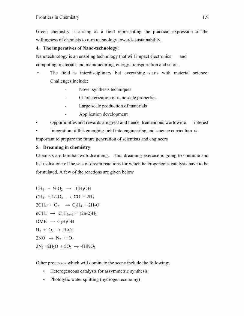
5. Dreaming in chemistry
Chemists are familiar with dreaming. This dreaming exercise is going to continue and
list us list one of the sets of dream reactions for which heterogeneous catalysts have to be
formulated. A few of the reactions are given below
CH4 + ½ O2 → CH3OH
CH4 + 1/2O2 → CO + 2H2
2CH4 + O2 → C2H4 + 2H2O
nCH4 → CnH2n+2 + (2n-2)H2
DME → C2H5OH
H2 + O2 → H2O2
2NO → N2 + O2
2N2 +2H2O + 5O2 → 4HNO3
Other processes which will dominate the scene include the following:
• Heterogeneous catalysts for assymmetric synthesis
• Photolytic water splitting (hydrogen economy)

Introduction to Frontiers in Chemistry
1.10
• Biomimetics, synthetic enzymes
• Non-thermal processes in general
In addition to this heterogeneous catalysis, it is possible that the sensors field also will
face considerable changes. This is because that we have learnt how to functionalize the
surfaces and hook bio-molecules on the surfaces which will remarkably change our
capability for detection and quantification. It is clear that chemists are in for a
tremendous change in the next few years. In Table 1 what are new in chemistry are
listed. It must be stated that this is only an indicative list and no way an exhaustive list.
Table 1. What is new in Chemistry?
• Atmospheric chemistry
• Biotechnology
• Cell biology
• Cell and molecular biology
• ceramics
Composites
• Computational Chemistry
• Crystallography
• Electrochemistry
• Harmonic analysis
• Liquid crystals
• Magnetic technology
• Marine geology and geo- physics
• Materials science
• Microbiology
• Microscopy
• Molecular biology
• Nanotechnology
• Oceanic sciences
• Optics and photonics
• Organic chemistry
• Particle technology
• Petroleum and geo-systems
Photonic band gap materials
• Photonics
• Polymers and plastics
• Process industries
• quantum computation
• Quantum optics and atom optics
• Radiocarbon
• Soil science
• Surface science
• Thermodynamics
• Tri-biology
• The ultra-fast phenomena
Chapter - 2 PERFORMANCE MATERIALS
M. Helen
Introduction
Performance or active or smart, material is a material, such as an alloy, ceramic, gel or
polymer, that is able to modify their functional characteristics if stimulated with electrical
or magnetic fields, temperature, light, pH and moisture. To date the most well
established application of performance materials are in the field of piezoelectric, shape
memory alloys, magneto/electro-strictive ceramics, magneto/electro-rheological fluids,
optics and structural monitoring. They can substitute dozens of actuators and sensors.
They are adaptive with the environmental conditions, permits to simplify components,
permits to reduce size, weight and cost and new functions can be developed.
Piezoelectric Materials
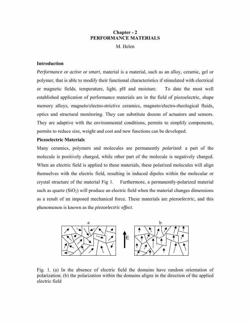
Many ceramics, polymers and molecules are permanently polarized: a part of the
molecule is positively charged, while other part of the molecule is negatively charged.
When an electric field is applied to these materials, these polarized molecules will align
themselves with the electric field, resulting in induced dipoles within the molecular or
crystal structure of the material Fig 1. Furthermore, a permanently-polarized material
such as quartz (SiO2) will produce an electric field when the material changes dimensions
as a result of an imposed mechanical force. These materials are piezoelectric, and this
phenomenon is known as the piezoelectric effect.
Fig. 1. (a) In the absence of electric field the domains have random orientation of polarization; (b) the polarization within the domains aligns in the direction of the applied electric field
E
a b
Performance Materials
2.2
The piezoelectric effect in various crystalline substances is a useful property that leads to
the detection of analytes (antibodies, ions, volatile gases and vapors). The piezoelectric
sensors (Chemical or biosensor) is thought to be one of the most sensitive analytical
instruments developed to date, being capable of detecting antigens in the picogram range.
Piezoelectric materials are also used in acoustic (sound) transducers, which convert
acoustic waves into electric fields, and electric fields into acoustic waves. Transducers
are found in telephones and musical instruments such as guitars and drums. Quartz, a
piezoelectric material, is often found in clocks and watches.
Ferroelectric Materials
Ferroelectric materials are crystals which are polar without an electric field being applied.
This state is also termed spontaneous polarization. Ferroelectric crystals similar to a
ferromagnetic material possess regions with uniform polarization called ferroelectric
domains. Within a domain, all the electric dipoles are aligned in the same direction.
Thin films of ferroelectric devices are being considered for application in
numerous electronic and electro-optic devices such as nonvolatile semiconductor
memories [1], optical waveguide devices, switching capacitors for integrated circuitry,
and imaging sensors. Non-volatile ferroelectric memories (NVMs) have several
advantages over other memory devices, mainly related to the unique features of write
operation (fast, with high endurance, without need for high voltage). Another competitive
advantage is the possibility of replicate functionality of several memory types in the same
device. In spite of this, they cannot be considered as the universal memory because of the
limited read endurance and the destructive read-out.
Shape Memory Alloys
Shape memory alloys are materials that remember their original shape and return to it
when heated, even if apparent residual deformation was introduced below a certain
temperature. The most effective and widely used alloys include NiTi, CuZnAl, and
CuAlNi.
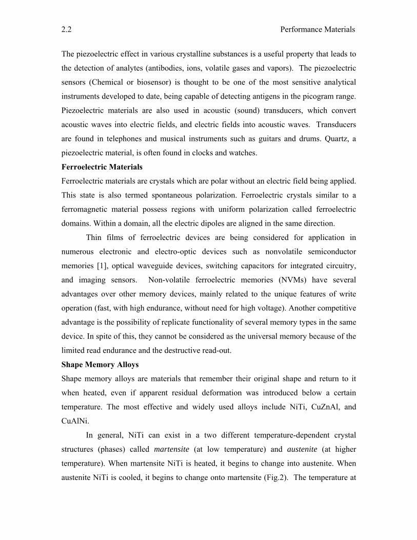
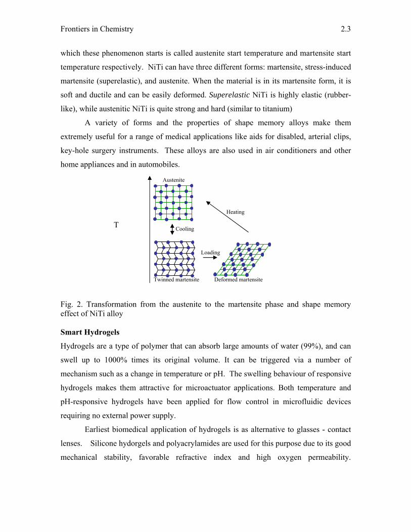
In general, NiTi can exist in a two different temperature-dependent crystal
structures (phases) called martensite (at low temperature) and austenite (at higher
temperature). When martensite NiTi is heated, it begins to change into austenite. When
austenite NiTi is cooled, it begins to change onto martensite (Fig.2). The temperature at
Frontiers in Chemistry
2.3
which these phenomenon starts is called austenite start temperature and martensite start
temperature respectively. NiTi can have three different forms: martensite, stress-induced
martensite (superelastic), and austenite. When the material is in its martensite form, it is
soft and ductile and can be easily deformed. Superelastic NiTi is highly elastic (rubber-
like), while austenitic NiTi is quite strong and hard (similar to titanium)
A variety of forms and the properties of shape memory alloys make them
extremely useful for a range of medical applications like aids for disabled, arterial clips,
key-hole surgery instruments. These alloys are also used in air conditioners and other
home appliances and in automobiles.
Fig. 2. Transformation from the austenite to the martensite phase and shape memory effect of NiTi alloy Smart Hydrogels
Hydrogels are a type of polymer that can absorb large amounts of water (99%), and can
swell up to 1000% times its original volume. It can be triggered via a number of
mechanism such as a change in temperature or pH. The swelling behaviour of responsive
hydrogels makes them attractive for microactuator applications. Both temperature and
pH-responsive hydrogels have been applied for flow control in microfluidic devices
requiring no external power supply.
Earliest biomedical application of hydrogels is as alternative to glasses - contact
lenses. Silicone hydorgels and polyacrylamides are used for this purpose due to its good
mechanical stability, favorable refractive index and high oxygen permeability.
Twinned martensite Deformed martensite
Austenite
Heating
Cooling
Loading
T
Performance Materials
2.4
Degradable poly(2-hydroxyethyl methacrylate) hydrogel with well-defined architectures
are used as scaffolds in tissue engineering.
Magneto/Electro-strictive Materials
Magnetostriction is the material property that causes a material to change its length when
subjected to an electromagnetic field. Magnetostriction properties also cause materials to
generate electromagnetic fields when they are deformed by an external force.
Magnetostrictive materials can thus be used as sensors and actuators.
The electrostrictive material undergoes dimensional change under the influence of
applied field. Electrostrictive materials strain proportionally to the square of the applied
voltage. They are unlike piezoelectric materials in that they are not poled. They are also
highly non-linear since they respond to the square of the applied voltage. A typical
electrostrictive material is lead magnesium niobate (PMN) used to construct an ultrasonic
transducer for non-destructive evaluation.
Magneto/Electro-rheological Materials
Magnetorheological materials experience a dramatic change in their viscosity by
application of a magnetic field. These materials typically consist of tiny iron particles
dispersed in a fluid. Magnetorheological fluids are used in car shocks, damping
washing machine vibration, prosthetic limbs, exercise equipment, and surface polishing
of machine parts.
Electrorheological materials exhibits rheological property in presence of an
applied electric field. Scientists at the Hong Kong University of Science and
Technology have developed a new class of electro-rheological fluids exhibiting 10 times
high yield stress (the strength of the materials in solid state) than the previously
achievable electro-rheological solid thus opening the vast potential of active mechanical
devices such as vibration dampers, shock absorbers, brakes, clutches and valves. This
electro-rheological fluid consists of dielectric microparticles dispersed in an insulating
liquid- silicone oil.
Electrochromic materials
An electrochromic material is one where a reversible color change takes place
upon reduction (gain of electrons) or oxidation (loss of electrons), on passage of electrical
current after the application of an appropriate electrode potential. Commercial
Frontiers in Chemistry
2.5
applications of electrochromic materials in devices include anti-glare car rear-view
mirrors, electrochromic strips as battery state-of-charge indicators and electrochromic
sunglasses. Proposed applications include ‘smart windows’ (based on modulation of
either the transmitted or reflected solar radiation) for use in cars and in buildings, re-
usable price labels, protective eyewear, controllable aircraft canopies, spacecraft thermal
control, and controllable light-reflective or light-transmissive display devices for optical
information and storage.
Transition metal coordination complexes are potentially useful as electrochromic
materials because of their intense coloration and redox reactivity. Chromophoric
properties arise from low-energy metal-to-ligand charge transfer (MLCT), intervalence
charge transfer, intraligand excitation, and related visible region electronic transitions.
Because these transitions involve valence electrons, chromophoric characteristics are
altered or eliminated upon oxidation or reduction of the complex. Polymeric systems
based on coordination complex monomer units, which have potential use in all-solid-state
systems, are frequently investigated.
A typical and most widely studied example is the tungsten trioxide (WO3) system,
since its electrochromism was first reported in 1969. Tungsten oxide has a nearly cubic
structure which may be simply described as an “empty-perovskite” type formed by WO6
octahedra that share corners. The empty space inside the cubes is considerable and this
provides the availability of a large number of interstitial sites where the guest ions can be
inserted. Tungsten trioxide, with all tungsten sites as oxidation state W6+, is a transparent
thin film. On electrochemical reduction, W5+ sites are generated to give the
electrochromic (blue coloration to the film) effect. Although, there is still controversy on
the detailed coloration mechanism, it is generally accepted that the injection and
extraction of electrons and metal cations (Li+, H+, etc.) play an important role. WO3 is a
cathodically ion insertion material. The blue coloration in the thin film of WO3 can be
erased by the electrochemical oxidation. The generalized equation can be written as,
Transparent Blue
WO3 + xM+ + e- MxW6+(1-x)W5+
xO3
Performance Materials
2.6
The fractional number of sites which are filled in the WO3 lattice is indicated by the
subscript x. At low x the films have an intense blue color caused by photoeffected
intervalence charge transfer (CT) between adjacent W5+ and W6+ sites. At higher x,
insertion irreversibly forms a metallic “bronze” which is red or golden in color. The
process is promoted by cathodic polarization which induces ion insertion and electron
injection: the inserted ions expand the lattice of the guest oxide while the compensating
electrons modify its electronic structure and in turn its optical properties. It can be stated
simply that the injected electrons are trapped by a W6+ forming a W5+ while M+ remains
ionized in the interstitial sites of the WO3 lattice. This gives rise to the formation of
tungsten bronze having electrical and optical properties different from those of the
pristine oxide. In fact, the pristine state WO3 is a pale-yellow and a poor electrical
conductor, while in the intercalated MxWO3 state it becomes highly conducting and blue
in color.
Conclusion
The significant increase of the level of living and production is connected more often
with the launching of new materials with better properties. The concept of engineering
materials and structures which respond to their environment is a significant concept.
The technological benefits of performance or smart or active materials have begun to be
identified and exploited in a wide range of applications from aerospace, to civil
engineering and domestic products. It is therefore important that the technological and
financial implications of these materials and structures are addressed.
References
1. R. Zambrano, Mater. Sci. Semicond. Process., 5 (2003) 305
2. S.J. Bryant, J. L. Cuy, K.D. Hauch and B.D. Ratner, Biomaterials, 28 (2007) 2978
3. http://www.cs.ualberta.ca/~database/MEMS/sma_mems/index2.html
4. R. J. Mortimer, A. L. Dyer and J. R. Reynolds, Displays, 27(2006) 2
Chapter - 3 COMPOSITE MATERIALS
P. Satyananda Kishore
There is an immense need of materials and systems that must in future aim at higher
levels of sophistication and miniaturization, be recyclable and respect the environment,
be reliable and consume less energy. Composite materials are the perfect option to
achieve the above goals. Composite materials already made their impact in much
scientific advancement. For example composite materials usage has increased in number
of products, starting from simple consumer goods to advanced aerospace space
structures. The composite materials are nothing but hybrid materials formed by
integration of two or more materials. They have different properties from their
constituents. The engineering of these materials associates with the meeting the desired
properties. The remarkable enhancement in the physical and chemical properties of the
composite materials with slight modification of constituents drew the attention of the
world towards these composite materials. The ability of these materials has extended
their applications in many research fields for specific applications because of the above
mentioned tunable properties.
Composite materials can be classified based on the presence of polymer as the
one constituent in the composite i.e, polymer based composites and non-polymer based
composites. The majority of composite materials are polymer based composites. The
interesting materials among the polymer based composites are organic – inorganic
composite materials, as these composite materials can solve the challenges in the field of
future technology such as energy supply, storage and production(fuel cells, batteries,
super capacitors, solar cells) and information technology. Ideally, the portioning of the
inorganic and organic species on the nanometer scale is expected to creat a homogeneous
composite showing the advantageous physico-chemical properties of both moieties. To
date for the organic moiety, the main focus of research has been on polymers( e.g. proton
exchange membranes in fuel cells). Attractive candidates for the inorganic parts are semi
conductors, (such as TiO2, CdS) and magnetic oxides. One of the most prominent recent
examples of such nanocomposites are novel solidstate solar cells. They are based on films
Composite Materials
3.2
containing semiconductive, nanocrystalline TiO2, an electrolyte and a sensitizing dye.
Further important examples of inorganic components are magnetic nanoparticles, such as
Fe2O3, which could be used for any kind of fluidic magnetic material. Considering these
potential applications, composites should fulfill the following requirements (among
others): high conductivity of the electrolyte, low vapor pressure and reasonable thermal
stability of the organic part (with respect to the conductivity, etc.), optimized viscosity,
homogenous distribution of the inorganic and organic phases on the nanometer scale (no
macroscopic phase separation), solvent- free processing, a reasonable chemical stability
(electrochemical, redox, and hydrolytic stability) and improved processing properties
with regard to fluidity requirements (films). The properties of the inorganic and organic
species should be maintained in the composite, but eventually also new desired properties
could be obtained. These composites can also used to decrease other properties like
electrical conductivity or permeability for gases like oxygen or water vapor. Organic-
inorganic hybrid materials allowed the development of new materials for industrial
applications in many areas: optics, electronics, ionics, mechanics, energy, environment,
biology, medicine for example as membranes and separation devices, functional smart
coatings, fuel and solar cells, catalysis, sensors and intelligent therapeutic vectors that
combine targeting, imaging, therapy and controlled release properties.
Several organic–inorganic composite materials are existing in nature. Nature has
remarkable ability of combining the organic and inorganic components at the nanoscale.
This allows the construction of several natural materials that found a compromise
between different properties of functions (mechanics, density, permeability, colour,
hydrophobia, etc.). This high level integration associates several aspects: miniaturization
whose object is to accommodate a maximum of elementary functions in a small volume,
hybridization between organic and inorganic components optimizing complementary
possibilities, functions and hierarchy. As far as man made composite materials are
concerned, the possibility to combine properties of organic-inorganic components for
materials design and processing is a very old challenge that likely started since ages
(Egyptian inks, green bodies of china ceramics etc.).
The organic – inorganic composites are not simply physical mixtures. The
constituents of organic and inorganic parts form miscible homogeneously composite
Frontiers in Chemistry
3.3
systems or heterogeneous systems where at least one of the components domains has a
dimention ranging some Ǻ to several nanomaterials.
The properties of these composite materials are not only the sum of the individual
contributions of both phases, but the role of the interfaces could be predominant. Based
on the nature of the interface these materials can be divided into two classes.
class I, organic and inorganic components are embedded and only weak bonds (hydrogen,
vander Waals or ionic bonds) give the cohesion to the whole structure. In class II
materials, the two phases are linked together through strong chemical bonds (covalent or
iono-covalent bonds).
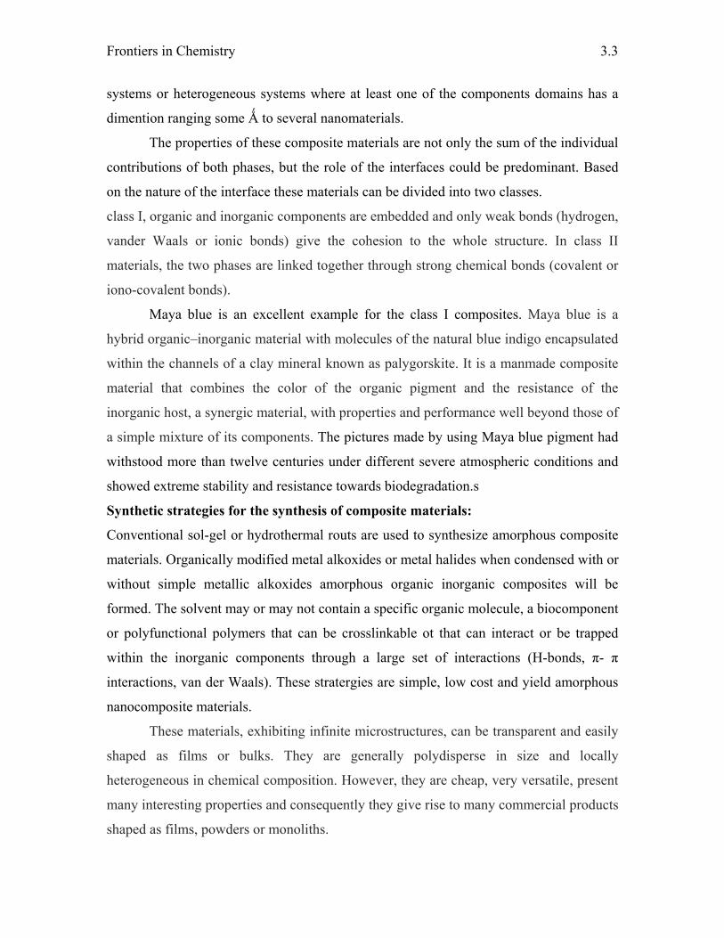
Maya blue is an excellent example for the class I composites. Maya blue is a
hybrid organic–inorganic material with molecules of the natural blue indigo encapsulated
within the channels of a clay mineral known as palygorskite. It is a manmade composite
material that combines the color of the organic pigment and the resistance of the
inorganic host, a synergic material, with properties and performance well beyond those of
a simple mixture of its components. The pictures made by using Maya blue pigment had
withstood more than twelve centuries under different severe atmospheric conditions and
showed extreme stability and resistance towards biodegradation.s
Synthetic strategies for the synthesis of composite materials:
Conventional sol-gel or hydrothermal routs are used to synthesize amorphous composite
materials. Organically modified metal alkoxides or metal halides when condensed with or
without simple metallic alkoxides amorphous organic inorganic composites will be
formed. The solvent may or may not contain a specific organic molecule, a biocomponent
or polyfunctional polymers that can be crosslinkable ot that can interact or be trapped
within the inorganic components through a large set of interactions (H-bonds, π- π
interactions, van der Waals). These stratergies are simple, low cost and yield amorphous
nanocomposite materials.
These materials, exhibiting infinite microstructures, can be transparent and easily
shaped as films or bulks. They are generally polydisperse in size and locally
heterogeneous in chemical composition. However, they are cheap, very versatile, present
many interesting properties and consequently they give rise to many commercial products
shaped as films, powders or monoliths.
Composite Materials
3.4
The use of bridged precursors such as silsesquioxanes X3Si–R9–SiX3 (R9 is an organic
spacer, X = Cl, Br, OR) allow the formation of homogeneous molecular hybrid organic–
inorganic materials which have a better degree of local organisation. In recent work, the
organic spacer has been complemented by using two terminal functional groups (urea
type). The combination within the organic bridging component of aromatic or alkyl
groups and urea groups allows better self-assembly through the capability of the organic
moieties to establish both strong hydrogen bond networks and efficient packing via p–p
or hydrophobic interactions.
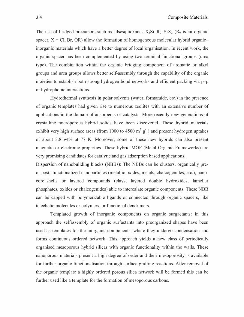
Hydrothermal synthesis in polar solvents (water, formamide, etc.) in the presence
of organic templates had given rise to numerous zeolites with an extensive number of
applications in the domain of adsorbents or catalysts. More recently new generations of
crystalline microporous hybrid solids have been discovered. These hybrid materials
exhibit very high surface areas (from 1000 to 4500 m2 g-1) and present hydrogen uptakes
of about 3.8 wt% at 77 K. Moreover, some of these new hybrids can also present
magnetic or electronic properties. These hybrid MOF (Metal Organic Frameworks) are
very promising candidates for catalytic and gas adsorption based applications.
Dispersion of nanobuliding blocks (NBBs): The NBBs can be clusters, organically pre-
or post- functionalized nanoparticles (metallic oxides, metals, chalcogenides, etc.), nano-
core–shells or layered compounds (clays, layered double hydroxides, lamellar
phosphates, oxides or chalcogenides) able to intercalate organic components. These NBB
can be capped with polymerizable ligands or connected through organic spacers, like
telechelic molecules or polymers, or functional dendrimers.
Templated growth of inorganic components on organic surgactants: in this
approach the selfassembly of organic surfactants into preorganized shapes have been
used as templates for the inorganic components, where they undergo condensation and
forms continuous ordered network. This approach yields a new class of periodically
organised mesoporous hybrid silicas with organic functionality within the walls. These
nanoporous materials present a high degree of order and their mesoporosity is available
for further organic functionalisation through surface grafting reactions. After removal of
the organic template a highly ordered porous silica network will be formed this can be
further used like a template for the formation of mesoporous carbons.
Frontiers in Chemistry
3.5
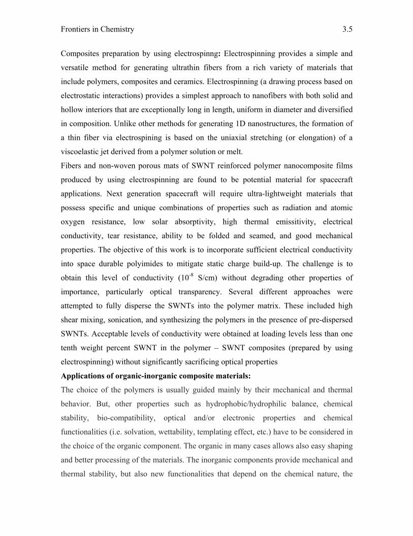
Composites preparation by using electrospinng: Electrospinning provides a simple and
versatile method for generating ultrathin fibers from a rich variety of materials that
include polymers, composites and ceramics. Electrospinning (a drawing process based on
electrostatic interactions) provides a simplest approach to nanofibers with both solid and
hollow interiors that are exceptionally long in length, uniform in diameter and diversified
in composition. Unlike other methods for generating 1D nanostructures, the formation of
a thin fiber via electrospining is based on the uniaxial stretching (or elongation) of a
viscoelastic jet derived from a polymer solution or melt.
Fibers and non-woven porous mats of SWNT reinforced polymer nanocomposite films
produced by using electrospinning are found to be potential material for spacecraft
applications. Next generation spacecraft will require ultra-lightweight materials that
possess specific and unique combinations of properties such as radiation and atomic
oxygen resistance, low solar absorptivity, high thermal emissitivity, electrical
conductivity, tear resistance, ability to be folded and seamed, and good mechanical
properties. The objective of this work is to incorporate sufficient electrical conductivity
into space durable polyimides to mitigate static charge build-up. The challenge is to
obtain this level of conductivity (10-8 S/cm) without degrading other properties of
importance, particularly optical transparency. Several different approaches were
attempted to fully disperse the SWNTs into the polymer matrix. These included high
shear mixing, sonication, and synthesizing the polymers in the presence of pre-dispersed
SWNTs. Acceptable levels of conductivity were obtained at loading levels less than one
tenth weight percent SWNT in the polymer – SWNT composites (prepared by using
electrospinning) without significantly sacrificing optical properties
Applications of organic-inorganic composite materials:
The choice of the polymers is usually guided mainly by their mechanical and thermal
behavior. But, other properties such as hydrophobic/hydrophilic balance, chemical
stability, bio-compatibility, optical and/or electronic properties and chemical
functionalities (i.e. solvation, wettability, templating effect, etc.) have to be considered in
the choice of the organic component. The organic in many cases allows also easy shaping
and better processing of the materials. The inorganic components provide mechanical and
thermal stability, but also new functionalities that depend on the chemical nature, the
Composite Materials
3.6
structure, the size, and crystallinity of the inorganic phase (silica, transition metal oxides,
metallic phosphates, nanoclays, nanometals, metal chalcogenides). Indeed, the inorganic
component can implement or improve electronic, magnetic and redox properties, density,
refraction index etc.
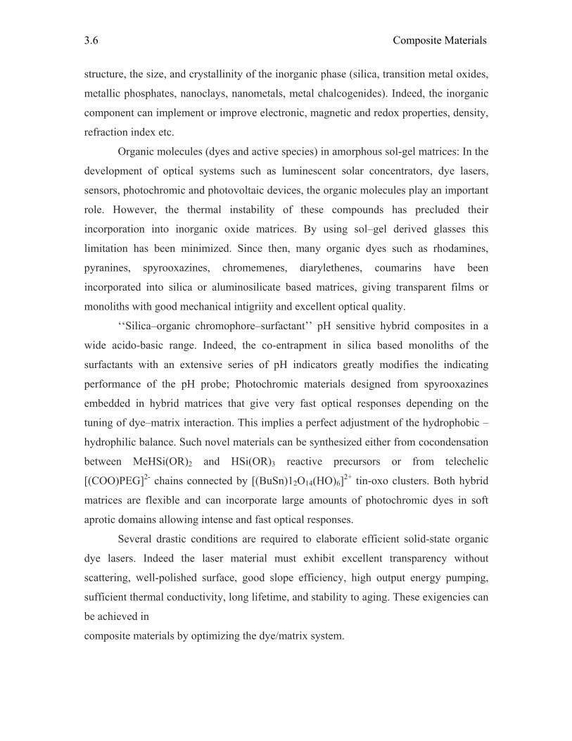
Organic molecules (dyes and active species) in amorphous sol-gel matrices: In the
development of optical systems such as luminescent solar concentrators, dye lasers,
sensors, photochromic and photovoltaic devices, the organic molecules play an important
role. However, the thermal instability of these compounds has precluded their
incorporation into inorganic oxide matrices. By using sol–gel derived glasses this
limitation has been minimized. Since then, many organic dyes such as rhodamines,
pyranines, spyrooxazines, chromemenes, diarylethenes, coumarins have been
incorporated into silica or aluminosilicate based matrices, giving transparent films or
monoliths with good mechanical intigriity and excellent optical quality.
‘‘Silica–organic chromophore–surfactant’’ pH sensitive hybrid composites in a
wide acido-basic range. Indeed, the co-entrapment in silica based monoliths of the
surfactants with an extensive series of pH indicators greatly modifies the indicating
performance of the pH probe; Photochromic materials designed from spyrooxazines
embedded in hybrid matrices that give very fast optical responses depending on the
tuning of dye–matrix interaction. This implies a perfect adjustment of the hydrophobic –
hydrophilic balance. Such novel materials can be synthesized either from cocondensation
between MeHSi(OR)2 and HSi(OR)3 reactive precursors or from telechelic
[(COO)PEG]2- chains connected by [(BuSn)12O14(HO)6]2+ tin-oxo clusters. Both hybrid
matrices are flexible and can incorporate large amounts of photochromic dyes in soft
aprotic domains allowing intense and fast optical responses.
Several drastic conditions are required to elaborate efficient solid-state organic
dye lasers. Indeed the laser material must exhibit excellent transparency without
scattering, well-polished surface, good slope efficiency, high output energy pumping,
sufficient thermal conductivity, long lifetime, and stability to aging. These exigencies can
be achieved in
composite materials by optimizing the dye/matrix system.
Frontiers in Chemistry
3.7
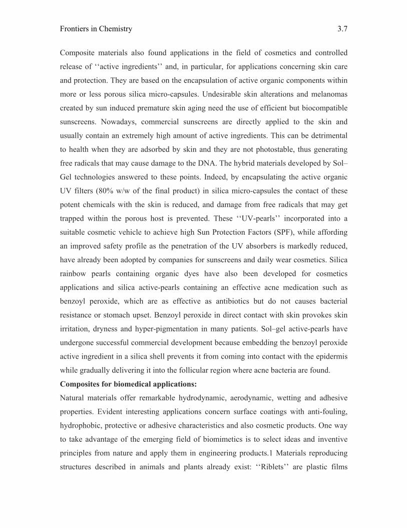
Composite materials also found applications in the field of cosmetics and controlled
release of ‘‘active ingredients’’ and, in particular, for applications concerning skin care
and protection. They are based on the encapsulation of active organic components within
more or less porous silica micro-capsules. Undesirable skin alterations and melanomas
created by sun induced premature skin aging need the use of efficient but biocompatible
sunscreens. Nowadays, commercial sunscreens are directly applied to the skin and
usually contain an extremely high amount of active ingredients. This can be detrimental
to health when they are adsorbed by skin and they are not photostable, thus generating
free radicals that may cause damage to the DNA. The hybrid materials developed by Sol–
Gel technologies answered to these points. Indeed, by encapsulating the active organic
UV filters (80% w/w of the final product) in silica micro-capsules the contact of these
potent chemicals with the skin is reduced, and damage from free radicals that may get
trapped within the porous host is prevented. These ‘‘UV-pearls’’ incorporated into a
suitable cosmetic vehicle to achieve high Sun Protection Factors (SPF), while affording
an improved safety profile as the penetration of the UV absorbers is markedly reduced,
have already been adopted by companies for sunscreens and daily wear cosmetics. Silica
rainbow pearls containing organic dyes have also been developed for cosmetics
applications and silica active-pearls containing an effective acne medication such as
benzoyl peroxide, which are as effective as antibiotics but do not causes bacterial
resistance or stomach upset. Benzoyl peroxide in direct contact with skin provokes skin
irritation, dryness and hyper-pigmentation in many patients. Sol–gel active-pearls have
undergone successful commercial development because embedding the benzoyl peroxide
active ingredient in a silica shell prevents it from coming into contact with the epidermis
while gradually delivering it into the follicular region where acne bacteria are found.
Composites for biomedical applications:
Natural materials offer remarkable hydrodynamic, aerodynamic, wetting and adhesive
properties. Evident interesting applications concern surface coatings with anti-fouling,
hydrophobic, protective or adhesive characteristics and also cosmetic products. One way
to take advantage of the emerging field of biomimetics is to select ideas and inventive
principles from nature and apply them in engineering products.1 Materials reproducing
structures described in animals and plants already exist: ‘‘Riblets’’ are plastic films
Composite Materials
3.8
covered by microscopic grooves inspired by shark or dolphin skin that are placed on
airplane wings in order to reduce the hydrodynamic trail and economize fuel.
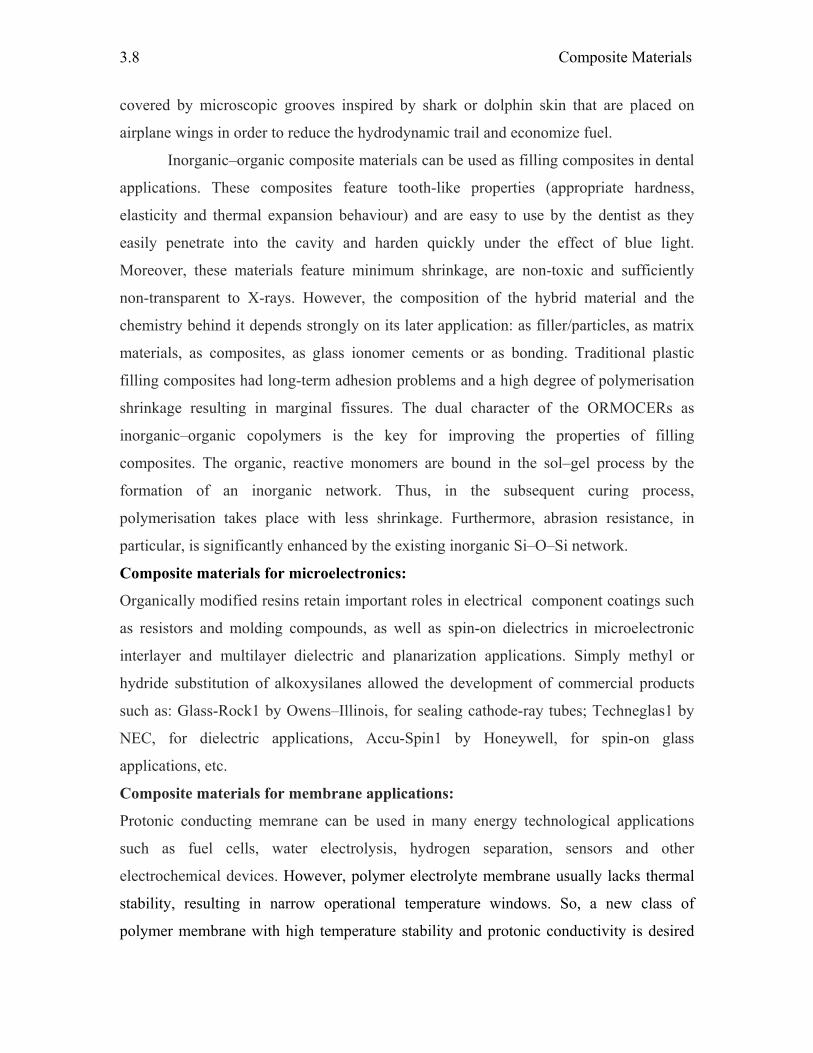
Inorganic–organic composite materials can be used as filling composites in dental
applications. These composites feature tooth-like properties (appropriate hardness,
elasticity and thermal expansion behaviour) and are easy to use by the dentist as they
easily penetrate into the cavity and harden quickly under the effect of blue light.
Moreover, these materials feature minimum shrinkage, are non-toxic and sufficiently
non-transparent to X-rays. However, the composition of the hybrid material and the
chemistry behind it depends strongly on its later application: as filler/particles, as matrix
materials, as composites, as glass ionomer cements or as bonding. Traditional plastic
filling composites had long-term adhesion problems and a high degree of polymerisation
shrinkage resulting in marginal fissures. The dual character of the ORMOCERs as
inorganic–organic copolymers is the key for improving the properties of filling
composites. The organic, reactive monomers are bound in the sol–gel process by the
formation of an inorganic network. Thus, in the subsequent curing process,
polymerisation takes place with less shrinkage. Furthermore, abrasion resistance, in
particular, is significantly enhanced by the existing inorganic Si–O–Si network.
Composite materials for microelectronics:
Organically modified resins retain important roles in electrical component coatings such
as resistors and molding compounds, as well as spin-on dielectrics in microelectronic
interlayer and multilayer dielectric and planarization applications. Simply methyl or
hydride substitution of alkoxysilanes allowed the development of commercial products
such as: Glass-Rock1 by Owens–Illinois, for sealing cathode-ray tubes; Techneglas1 by
NEC, for dielectric applications, Accu-Spin1 by Honeywell, for spin-on glass
applications, etc.
Composite materials for membrane applications:
Protonic conducting memrane can be used in many energy technological applications
such as fuel cells, water electrolysis, hydrogen separation, sensors and other
electrochemical devices. However, polymer electrolyte membrane usually lacks thermal
stability, resulting in narrow operational temperature windows. So, a new class of
polymer membrane with high temperature stability and protonic conductivity is desired
Frontiers in Chemistry
3.9
for many industrial applications. This has been achieved by preparing organi-inorganic
composite membranes. In these membranes the inorganic components gives the stability
and required protonic conductivity and the organic polymers enhances the flexibility to
process it into thin films.
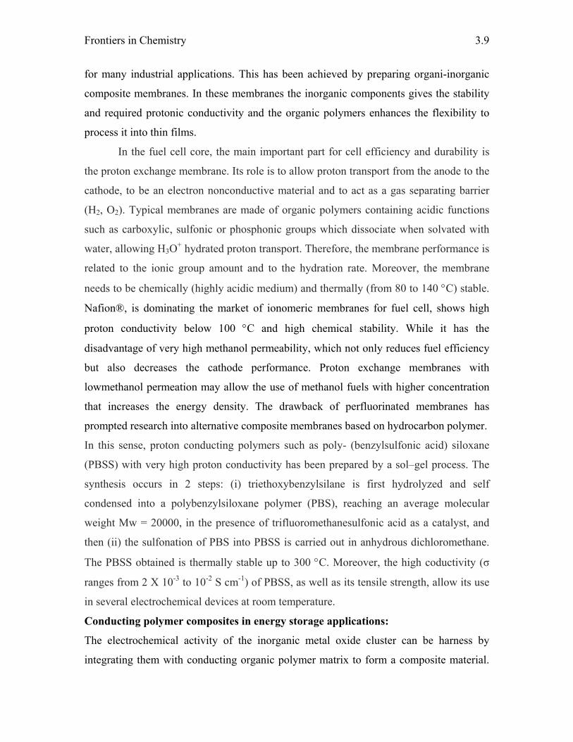
In the fuel cell core, the main important part for cell efficiency and durability is
the proton exchange membrane. Its role is to allow proton transport from the anode to the
cathode, to be an electron nonconductive material and to act as a gas separating barrier
(H2, O2). Typical membranes are made of organic polymers containing acidic functions
such as carboxylic, sulfonic or phosphonic groups which dissociate when solvated with
water, allowing H3O+ hydrated proton transport. Therefore, the membrane performance is
related to the ionic group amount and to the hydration rate. Moreover, the membrane
needs to be chemically (highly acidic medium) and thermally (from 80 to 140 °C) stable.
Nafion®, is dominating the market of ionomeric membranes for fuel cell, shows high
proton conductivity below 100 °C and high chemical stability. While it has the
disadvantage of very high methanol permeability, which not only reduces fuel efficiency
but also decreases the cathode performance. Proton exchange membranes with
lowmethanol permeation may allow the use of methanol fuels with higher concentration
that increases the energy density. The drawback of perfluorinated membranes has
prompted research into alternative composite membranes based on hydrocarbon polymer.
In this sense, proton conducting polymers such as poly- (benzylsulfonic acid) siloxane
(PBSS) with very high proton conductivity has been prepared by a sol–gel process. The
synthesis occurs in 2 steps: (i) triethoxybenzylsilane is first hydrolyzed and self
condensed into a polybenzylsiloxane polymer (PBS), reaching an average molecular
weight Mw = 20000, in the presence of trifluoromethanesulfonic acid as a catalyst, and
then (ii) the sulfonation of PBS into PBSS is carried out in anhydrous dichloromethane.
The PBSS obtained is thermally stable up to 300 °C. Moreover, the high coductivity (σ
ranges from 2 X 10⁻³ to 10-2 S cm-1) of PBSS, as well as its tensile strength, allow its use
in several electrochemical devices at room temperature.
Conducting polymer composites in energy storage applications:
The electrochemical activity of the inorganic metal oxide cluster can be harness by
integrating them with conducting organic polymer matrix to form a composite material.
Composite Materials
3.10
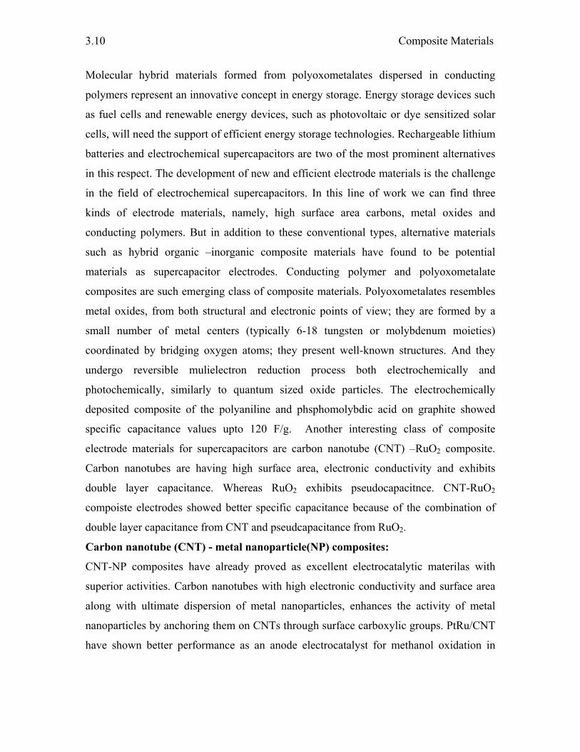
Molecular hybrid materials formed from polyoxometalates dispersed in conducting
polymers represent an innovative concept in energy storage. Energy storage devices such
as fuel cells and renewable energy devices, such as photovoltaic or dye sensitized solar
cells, will need the support of efficient energy storage technologies. Rechargeable lithium
batteries and electrochemical supercapacitors are two of the most prominent alternatives
in this respect. The development of new and efficient electrode materials is the challenge
in the field of electrochemical supercapacitors. In this line of work we can find three
kinds of electrode materials, namely, high surface area carbons, metal oxides and
conducting polymers. But in addition to these conventional types, alternative materials
such as hybrid organic –inorganic composite materials have found to be potential
materials as supercapacitor electrodes. Conducting polymer and polyoxometalate
composites are such emerging class of composite materials. Polyoxometalates resembles
metal oxides, from both structural and electronic points of view; they are formed by a
small number of metal centers (typically 6-18 tungsten or molybdenum moieties)
coordinated by bridging oxygen atoms; they present well-known structures. And they
undergo reversible mulielectron reduction process both electrochemically and
photochemically, similarly to quantum sized oxide particles. The electrochemically
deposited composite of the polyaniline and phsphomolybdic acid on graphite showed
specific capacitance values upto 120 F/g. Another interesting class of composite
electrode materials for supercapacitors are carbon nanotube (CNT) –RuO2 composite.
Carbon nanotubes are having high surface area, electronic conductivity and exhibits
double layer capacitance. Whereas RuO2 exhibits pseudocapacitnce. CNT-RuO2
compoiste electrodes showed better specific capacitance because of the combination of
double layer capacitance from CNT and pseudcapacitance from RuO2.
Carbon nanotube (CNT) - metal nanoparticle(NP) composites:
CNT-NP composites have already proved as excellent electrocatalytic materilas with
superior activities. Carbon nanotubes with high electronic conductivity and surface area
along with ultimate dispersion of metal nanoparticles, enhances the activity of metal
nanoparticles by anchoring them on CNTs through surface carboxylic groups. PtRu/CNT
have shown better performance as an anode electrocatalyst for methanol oxidation in
Frontiers in Chemistry
3.11
direct methanol fuel cells. In the same way Au/MWCNT showed remarkable
elecrocatalytic activity towards oxygen reduction in acid medium.
Stealth technology:
This technology has been used with aircrafts, ships and missiles in order to make them
less visible (ideally invisible) to radar, infrared and other detection methods.
Radar (Radio detection and ranging) is a system that uses electromagnetic waves
to identify the range, altitude, direction, or speed of both moving and fixed objects such
as aircrafts, ships, motor vehicles, etc. A transmitter emits radio waves, which are then
reflected by the target and detected by a receiver, typically in the same location as the
transmitter. The radar antenna measures the time it takes for the reflection to arrive and
with that information can tell how far away the object is. In order to make the objects
such as aircrafts not be detected by radars, we have to make the body of the aircraft in
such a way that it will not reflect the radio waves send by the radar.
The metal body of an airplane is very good at reflecting radar signals and this
makes it easy to find and track airplanes with radar equipment. The aim of stealth
technology is to make an airplane invisible to radar. The ability to be undetected by radar,
or perhaps less detectable, clearly gives a major advantage over enemy.
There are two different ways to create invisibility.There are two different ways to create
invisibility:
• The airplane can be shaped so that any radar signals it reflects are reflected away
from the radar equipment.
• The airplane can be covered in materials that absorb radar signals.
The use of radar absorbing materials (RAM) for the suppression of radar signature and
the removal of false echoes from radar screens has been used for many years. The
majority of the materials used have been of a parasitic nature, usually in the form of flat
flexible sheets, heavily loaded with iron or ferrite powders that are bonded to the
structure requiring treatment. Because of the heavy coatings the weight if the aircraft
increases, it’s a hurdle. By reducing in weight of the aircraft the air friction during the
motion can be reduced and thereby the speed can be increased. We can achieve this by
incorporating the radar absorbing property within the structure rather than applying it
parasitically would reduce the prohibitive weight penalties.

Composite Materials
3.12
Hybrid coatings based on organically modified silicate (Ormosil)/Ni0.5Zn0.5Fe2O4 (10–
30 wt.%) were synthesized through a sol–gel technique. Tetraethylenepentamine, 3-
glycidoxypropyltrimethoxysilane, tetraethoxysilane and Ni0.5Zn0.5Fe2O4 were used as
precursors for the hybrid coatings. These hybrid films were deposited via spin coating
onto an aluminum alloy in order to improve the corrosion protection and to act as infrared
stealth coatings.
References:
1. B. D. Li, Y. Xia , Adv., Mater.,16 (2004)1151
2. P. Gomez-Romero and C. Sanchez, New J. Chem., 1 (2005) 57
3. N. Lapidot, O. Gans, F. Biagini, L. Sosonkin and C. Rottmann, Euro cosmetics, 1
(2000) 20.
4. H. Wolter and W. Storch, J. Sol–Gel Sci. Technol., 2 (1994) 93
5. F. Rousseau, C. Poinsignon, J. Garcia and M. Popall, Chem. Mater., 7 (1995) 828
6. J. Xi, J. Wang, L. Yu, X. Qiu, L. Chen, Chem. Commun., 2007, 1656
7. Y. T. Kim, K. Tadai, T. Mitani, J. Mater. Chem, , 15 (2005) 4914
8. Nadezda Alexeyeva, Timo Laaksonen, Kyösti Kontturi, Fakhradin Mirkhalaf, David
J. Schiffrin and Kaido Tammeveski, Electrochem. Commun., 8 (2006) 1475
9. A. K. C. Gallegos, M. L. Cantu, N. C. Pastor, P. G. Romero, Adv. Funct. Mater., 15
(2005), 1125
10. P. T. Curtis, Advanced performance materials, 3 (1996) 279

Chapter - 4 NANOMATERIALS
S. Navaladian
Introduction
The word "nano" originates from the Greek word for dwarf, and used to mean something
tiny. As a prefix for a unit of time or length, it means one billionth of that unit. One
nanometer (nm) is 10-9 meter. Nanomateials represents those materials that are in the size
in the nano range. Bulk materials can be defined as the material made out large number
atoms or ions that give rise to dimension of micro range or more. Many water molecules
can easily occupy a sphere 1 nm in diameter. The DNA double helix is approximately 2
nm wide. The next question that arises in one’s mind is as to how those small particles
can be seen. Even the small aunt cannot be seen through our eye clearly in spite of the
fact that its size is of millimeter range. When some microscopist could answere this
question, the acceleration in the field of nanochemistry was tremendous. Today, one can
see the word nano everywhere even in the commercial advertisement. It is because of
versatile applications of nanomaterials. In general, as per the human nature, one believes
some information only if he could see or notice it. That is the reason nanochemistry has
developed only after the invention of electron microscopes. Today the researches in
various fields are working in and around this nanochemistry. Apart from the interest, all
our researches look some thing useful for our mankind. The proverb ‘necessity is the
mother of invention’ has some meaning. In that way if one looks at the nanochemistry the
applications are countless. It is because that entirely different properties and characters
are exhibited by the materials in the nanorange.
Before going into the details of the nanomaterials, the basics of the nanochemistry
is important. The morphology of the particles also affects the properties. In general, apart
from the spherical shape, the material adopts so many other morphologies. The formation
of non spherical morphology is due to some restriction during their growth. These
materials are known as nanostructure materials. They are categorized into the three as to
1, 2 and 3-dimensional materials as shown in the Figure. 1.
Nanomaterials
4.2
Fig. 1. The materials in various dimensions
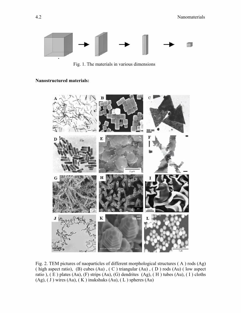
Nanostructured materials:
Fig. 2. TEM pictures of naoparticles of different morphological structures ( A ) rods (Ag) ( high aspect ratio), (B) cubes (Au) , ( C ) triangular (Au) , ( D ) rods (Au) ( low aspect ratio ), ( E ) plates (Au), (F) strips (Au), (G) dendrites (Ag), ( H ) tubes (Au), ( I ) cloths (Ag), ( J ) wires (Au), ( K ) inukshuks (Au), ( L ) spheres (Au)
Frontiers in Chemistry
4.3
All the materials are found to be forming the nanostructured materials. Because of the
restricted growth of the materials the formation of various morphologies such as
nanorods, nanowires, nanotubes, nanoplates, triangles, nanocubes, hierarchical structures
take pace. Examples of these materials are shown in Figure 2. Because of different
dimension in different directions of these materials, the band structure varies from the
spherical to other morphologies as shown in Figure. 4.
Apart from these, hierarchical structures are also known (Figure.2 (K)), where
primary building blocks associate into more complex secondary structures that are
integrated into the next size level in the hierarchy. This organizational scheme continues
until the highest level in the hierarchy is reached. These hierarchical constructions may
exhibit unique properties that are not found in the individual components. Hierarchy is a
characteristic of many self-assembling biological structures and is beginning to emerge as
a hallmark of materials self-assembly that encompasses multiple length scales.
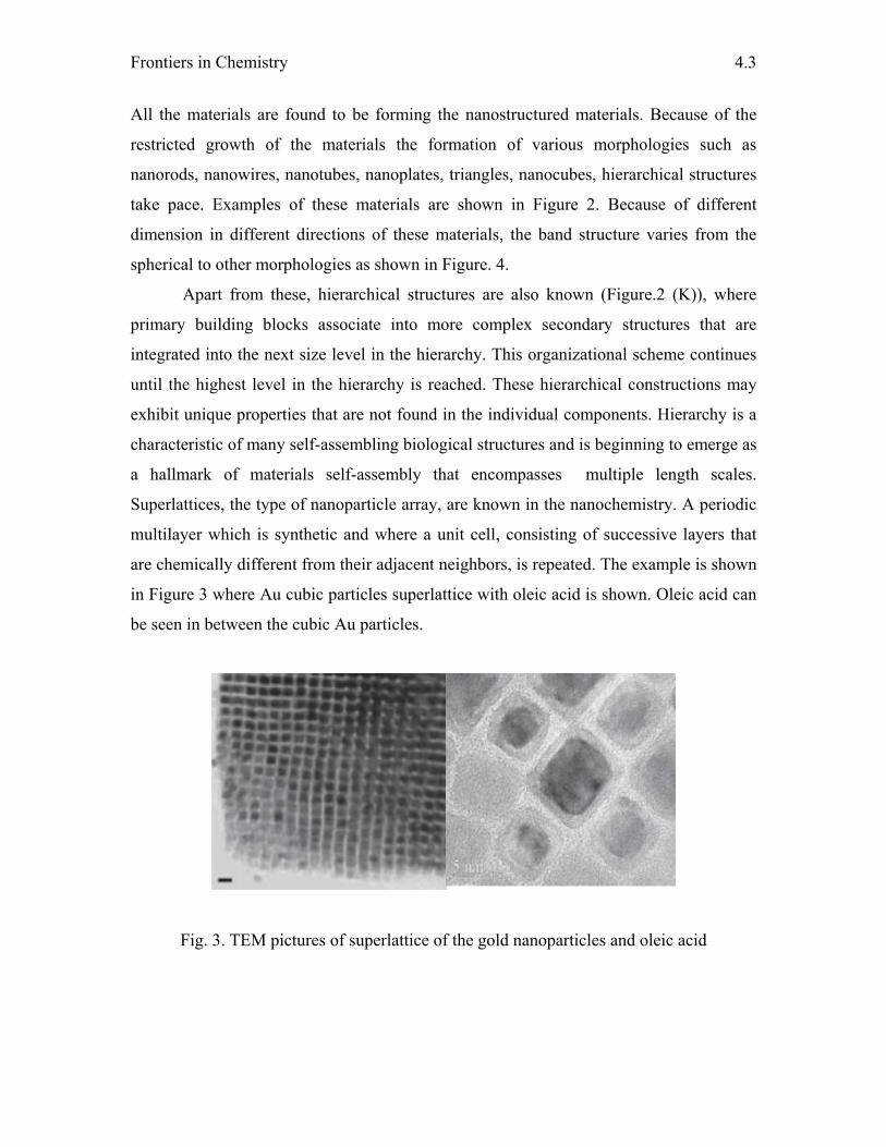
Superlattices, the type of nanoparticle array, are known in the nanochemistry. A periodic
multilayer which is synthetic and where a unit cell, consisting of successive layers that
are chemically different from their adjacent neighbors, is repeated. The example is shown
in Figure 3 where Au cubic particles superlattice with oleic acid is shown. Oleic acid can
be seen in between the cubic Au particles.
Fig. 3. TEM pictures of superlattice of the gold nanoparticles and oleic acid

Nanomaterials
4.4
Properties:
Fig. 4. The variation of the band gap (A) and the density of states (B), and band structure(C) variation with respect to the change in the morphogy of the Nanosemicondctor
C

Frontiers in Chemistry
4.5
The change in the properties of the nanomatreials as compared to the bulk materials is
tremendous. This change in the size makes these materials to have different electronic
changes in terms of energy and number of levels. This makes these materials behave
electronically different. These in turn alter the redox behavior of the materials. Physical
properties such as surface area also vary due to the availability of more interfaces in the
small range. The surface to volume ratio is more in the nanostate than in the bulk. Band
gap and density state diagram are shown in Figure 4.
Properties of nanomaterial that are different from bulk are variation of the redox
properties, band gap variation, anomalous melting points, enhance toughness and
strength, unusual crystal structures (in metals). As for the band gap, it increases as the
particle size decreases due to the loss of in-between energy levels during the size
reduction. This variation of band gap can be realized from the UV-Vis spectrum of the
corresponding materials. The blue shifts indicate the formation of the nano
semiconductors, namely, TiO2. This property is well exploited in the photocatalysis, that
is light harvesting.
In catalysis, these nanomaterials are efficient in terms of surface area and redox
properties. Au has been known as inactive material up to the last decade. However, it was
understood that Au is catalytically active when it is below 5 nm. This indicates that redox
properties are different when it is below 5 nm. Now the gold is known active for many
reactions. The problem of the size effect remains unclear. The making of these
nanomaterials need some specific methodology.
Synthesis of nano materials:
The major classification of synthesis of these nanomaterials is of two types,
1. Top down approach
2. Bottom up approach
Top-down approach:
The nanosized materials are prepared at the expense of the bulk material in this
technique. Examples are ball- milling and laser ablation techniques. These methods
enable one to synthesize the particles of polydispersity. Poly dispersity means the
particles of different size range. This is the disadvantage of this method.
Nanomaterials
4.6
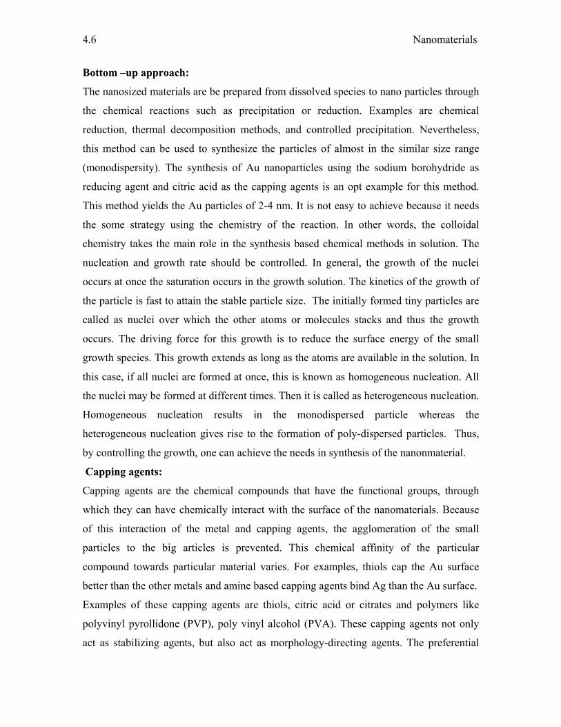
Bottom –up approach:
The nanosized materials are be prepared from dissolved species to nano particles through
the chemical reactions such as precipitation or reduction. Examples are chemical
reduction, thermal decomposition methods, and controlled precipitation. Nevertheless,
this method can be used to synthesize the particles of almost in the similar size range
(monodispersity). The synthesis of Au nanoparticles using the sodium borohydride as
reducing agent and citric acid as the capping agents is an opt example for this method.
This method yields the Au particles of 2-4 nm. It is not easy to achieve because it needs
the some strategy using the chemistry of the reaction. In other words, the colloidal
chemistry takes the main role in the synthesis based chemical methods in solution. The
nucleation and growth rate should be controlled. In general, the growth of the nuclei
occurs at once the saturation occurs in the growth solution. The kinetics of the growth of
the particle is fast to attain the stable particle size. The initially formed tiny particles are
called as nuclei over which the other atoms or molecules stacks and thus the growth
occurs. The driving force for this growth is to reduce the surface energy of the small
growth species. This growth extends as long as the atoms are available in the solution. In
this case, if all nuclei are formed at once, this is known as homogeneous nucleation. All
the nuclei may be formed at different times. Then it is called as heterogeneous nucleation.
Homogeneous nucleation results in the monodispersed particle whereas the
heterogeneous nucleation gives rise to the formation of poly-dispersed particles. Thus,
by controlling the growth, one can achieve the needs in synthesis of the nanonmaterial.
Capping agents:
Capping agents are the chemical compounds that have the functional groups, through
which they can have chemically interact with the surface of the nanomaterials. Because
of this interaction of the metal and capping agents, the agglomeration of the small
particles to the big articles is prevented. This chemical affinity of the particular
compound towards particular material varies. For examples, thiols cap the Au surface
better than the other metals and amine based capping agents bind Ag than the Au surface.
Examples of these capping agents are thiols, citric acid or citrates and polymers like
polyvinyl pyrollidone (PVP), poly vinyl alcohol (PVA). These capping agents not only
act as stabilizing agents, but also act as morphology-directing agents. The preferential
Frontiers in Chemistry
4.7
adsorption of capping agents on the particular plane of the nuclei leads to the formation
of anisotropic structures. It is worthwhile to mention that the growth rate of the different
plane varies due to there stability. However, this preferential growth of the capping
agents changes the fate of the growth by arresting the particular planes. This
cetyltrimethyammonium bromide (CTAB), a capping agent, preferentially adsorb at
{100} plane of the Au nuclei, so that formation of Au nanorods along the {111} direction
occur. In general, the preparations of any nanomaterial can be achieved by using the
suitable methodology. In literature, various methods are known for the synthesis of
nanomaterials. Some of the methods are template synthesis, solvotheremal and sol-gel
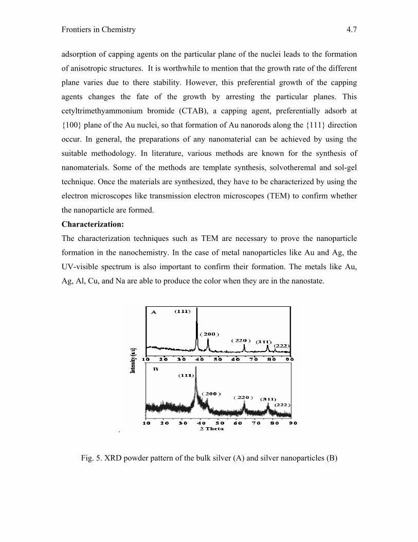
technique. Once the materials are synthesized, they have to be characterized by using the
electron microscopes like transmission electron microscopes (TEM) to confirm whether
the nanoparticle are formed.
Characterization:
The characterization techniques such as TEM are necessary to prove the nanoparticle
formation in the nanochemistry. In the case of metal nanoparticles like Au and Ag, the
UV-visible spectrum is also important to confirm their formation. The metals like Au,
Ag, Al, Cu, and Na are able to produce the color when they are in the nanostate.
.
Fig. 5. XRD powder pattern of the bulk silver (A) and silver nanoparticles (B)
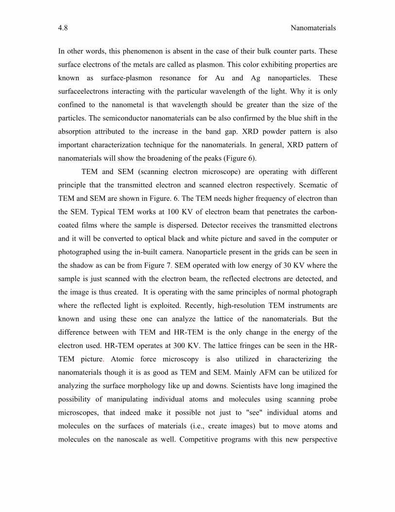
Nanomaterials
4.8
In other words, this phenomenon is absent in the case of their bulk counter parts. These
surface electrons of the metals are called as plasmon. This color exhibiting properties are
known as surface-plasmon resonance for Au and Ag nanoparticles. These
surfaceelectrons interacting with the particular wavelength of the light. Why it is only
confined to the nanometal is that wavelength should be greater than the size of the
particles. The semiconductor nanomaterials can be also confirmed by the blue shift in the
absorption attributed to the increase in the band gap. XRD powder pattern is also
important characterization technique for the nanomaterials. In general, XRD pattern of
nanomaterials will show the broadening of the peaks (Figure 6).
TEM and SEM (scanning electron microscope) are operating with different
principle that the transmitted electron and scanned electron respectively. Scematic of
TEM and SEM are shown in Figure. 6. The TEM needs higher frequency of electron than
the SEM. Typical TEM works at 100 KV of electron beam that penetrates the carbon-
coated films where the sample is dispersed. Detector receives the transmitted electrons
and it will be converted to optical black and white picture and saved in the computer or
photographed using the in-built camera. Nanoparticle present in the grids can be seen in
the shadow as can be from Figure 7. SEM operated with low energy of 30 KV where the
sample is just scanned with the electron beam, the reflected electrons are detected, and
the image is thus created. It is operating with the same principles of normal photograph
where the reflected light is exploited. Recently, high-resolution TEM instruments are
known and using these one can analyze the lattice of the nanomaterials. But the
difference between with TEM and HR-TEM is the only change in the energy of the
electron used. HR-TEM operates at 300 KV. The lattice fringes can be seen in the HR-
TEM picture. Atomic force microscopy is also utilized in characterizing the
nanomaterials though it is as good as TEM and SEM. Mainly AFM can be utilized for
analyzing the surface morphology like up and downs. Scientists have long imagined the
possibility of manipulating individual atoms and molecules using scanning probe
microscopes, that indeed make it possible not just to "see" individual atoms and
molecules on the surfaces of materials (i.e., create images) but to move atoms and
molecules on the nanoscale as well. Competitive programs with this new perspective
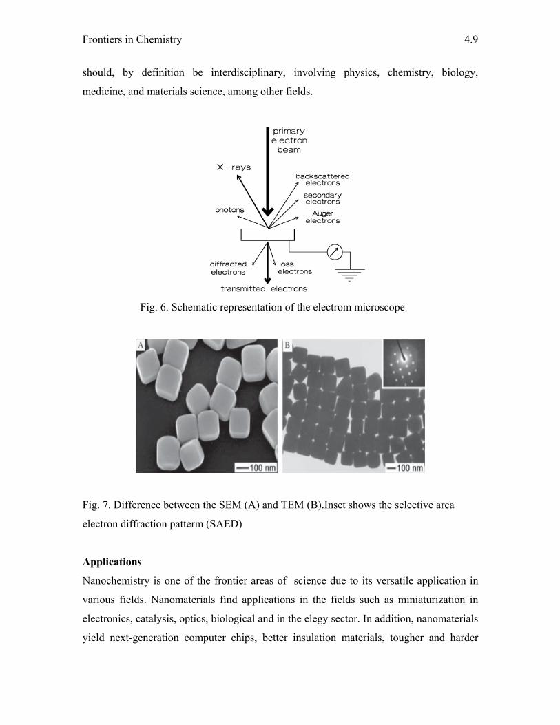
Frontiers in Chemistry
4.9
should, by definition be interdisciplinary, involving physics, chemistry, biology,
medicine, and materials science, among other fields.
Fig. 6. Schematic representation of the electrom microscope
Fig. 7. Difference between the SEM (A) and TEM (B).Inset shows the selective area
electron diffraction patterm (SAED)
Applications
Nanochemistry is one of the frontier areas of science due to its versatile application in
various fields. Nanomaterials find applications in the fields such as miniaturization in
electronics, catalysis, optics, biological and in the elegy sector. In addition, nanomaterials
yield next-generation computer chips, better insulation materials, tougher and harder
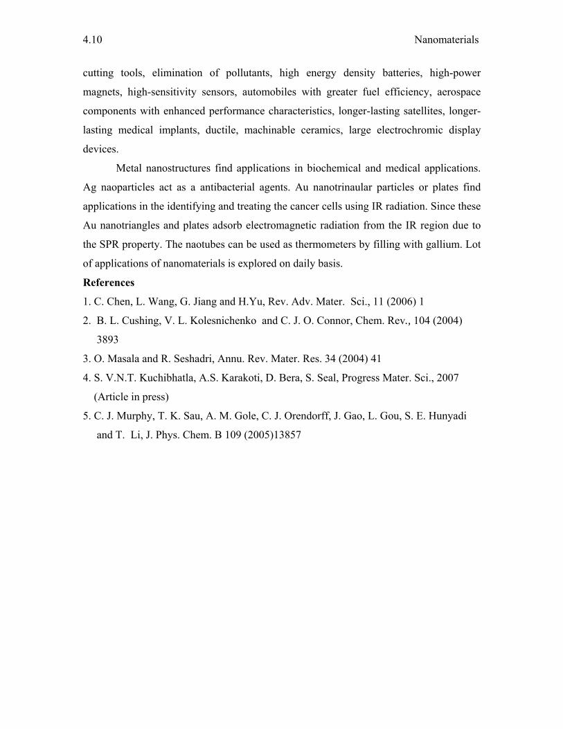
Nanomaterials
4.10
cutting tools, elimination of pollutants, high energy density batteries, high-power
magnets, high-sensitivity sensors, automobiles with greater fuel efficiency, aerospace
components with enhanced performance characteristics, longer-lasting satellites, longer-
lasting medical implants, ductile, machinable ceramics, large electrochromic display
devices.
Metal nanostructures find applications in biochemical and medical applications.
Ag naoparticles act as a antibacterial agents. Au nanotrinaular particles or plates find
applications in the identifying and treating the cancer cells using IR radiation. Since these
Au nanotriangles and plates adsorb electromagnetic radiation from the IR region due to
the SPR property. The naotubes can be used as thermometers by filling with gallium. Lot
of applications of nanomaterials is explored on daily basis.
References
1. C. Chen, L. Wang, G. Jiang and H.Yu, Rev. Adv. Mater. Sci., 11 (2006) 1
2. B. L. Cushing, V. L. Kolesnichenko and C. J. O. Connor, Chem. Rev., 104 (2004)
3893
3. O. Masala and R. Seshadri, Annu. Rev. Mater. Res. 34 (2004) 41
4. S. V.N.T. Kuchibhatla, A.S. Karakoti, D. Bera, S. Seal, Progress Mater. Sci., 2007
(Article in press)
5. C. J. Murphy, T. K. Sau, A. M. Gole, C. J. Orendorff, J. Gao, L. Gou, S. E. Hunyadi
and T. Li, J. Phys. Chem. B 109 (2005)13857
Chapter - 5 SILICON SUBSTITUTES
M. Sankaran
1. Introduction
1.1. General introduction to Silicon and its application
Silicon is the second most common element in the upper layer of the earth’s crust:
about 25% of the crust consists of silicon (only oxygen exceeds it in abundance).
However, silicon is usually not found free, but mainly in its oxides and silicates. Most
silicon oxides appear as sand, quartz, rock crystal, amethyst, agate, flint, and opal.
Most silicates appear as granite, hornblende, asbestos, feldspar, clay and mica.
Silicon (Si) belongs to the IVA family in the periodic table, which consists of
carbon, silicon, germanium, tin and lead. Its atomic number is 14, the outer electron
configuration of each of these atoms is s2p2. Carbon and silicon are nonmetals, while
tin and lead are metals, and germanium and gray tin are typical semiconductors.
Amorphous silicon is a brown, inflammable powder which can easily melt or
vaporized. Its specific gravity is 2.35. It can be easily reduced. Whereas crystalline
silicon is found, similar to carbon, very hard, melts at 1400 °C and vaporizes at high
temperatures. Silicon combines with many elements including boron, carbon,
titanium, and zirco zirconium in the electric furnace. It readily dissolves in molten
magnesium, copper, iron, and nickel to form silicides. Most oxides are reduced by
silicon at high temperatures. The physical and chemical properties of the silicon are
tabulated in Table 1.
Table 1. The physical and chemical properties of silicon
Silicon Data
Atomic Radius (Å): 1.46 Å
Atomic Volume cm3/mol : 12.1cm3/mol
Covalent Radius: 1.11 Å
Crystal Structure: Cubic face centered
Ionic Radius: 0.4 Å
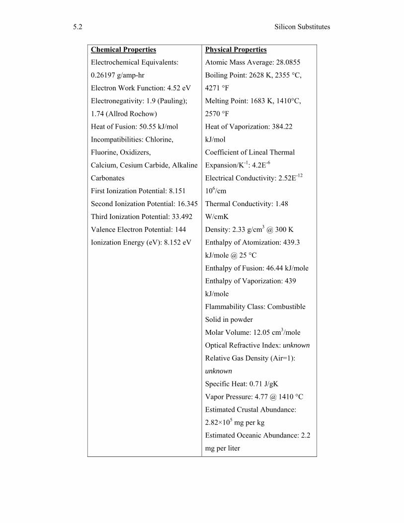
Silicon Substitutes
5.2
Chemical Properties
Electrochemical Equivalents:
0.26197 g/amp-hr
Electron Work Function: 4.52 eV
Electronegativity: 1.9 (Pauling);
1.74 (Allrod Rochow)
Heat of Fusion: 50.55 kJ/mol
Incompatibilities: Chlorine,
Fluorine, Oxidizers,
Calcium, Cesium Carbide, Alkaline
Carbonates
First Ionization Potential: 8.151
Second Ionization Potential: 16.345
Third Ionization Potential: 33.492
Valence Electron Potential: 144
Ionization Energy (eV): 8.152 eV
Physical Properties
Atomic Mass Average: 28.0855
Boiling Point: 2628 K, 2355 °C,
4271 °F
Melting Point: 1683 K, 1410°C,
2570 °F
Heat of Vaporization: 384.22
kJ/mol
Coefficient of Lineal Thermal
Expansion/K-1: 4.2E-6
Electrical Conductivity: 2.52E-12
106/cm
Thermal Conductivity: 1.48
W/cmK
Density: 2.33 g/cm3 @ 300 K
Enthalpy of Atomization: 439.3
kJ/mole @ 25 °C
Enthalpy of Fusion: 46.44 kJ/mole
Enthalpy of Vaporization: 439
kJ/mole
Flammability Class: Combustible
Solid in powder
Molar Volume: 12.05 cm3/mole
Optical Refractive Index: unknown
Relative Gas Density (Air=1):
unknown
Specific Heat: 0.71 J/gK
Vapor Pressure: 4.77 @ 1410 °C
Estimated Crustal Abundance:
2.82×10⁵ mg per kg
Estimated Oceanic Abundance: 2.2
mg per liter
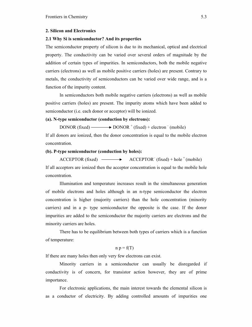
Frontiers in Chemistry
5.3
2. Silicon and Electronics
2.1 Why Si is semiconductor? And its properties
The semiconductor property of silicon is due to its mechanical, optical and electrical
property. The conductivity can be varied over several orders of magnitude by the
addition of certain types of impurities. In semiconductors, both the mobile negative
carriers (electrons) as well as mobile positive carriers (holes) are present. Contrary to
metals, the conductivity of semiconductors can be varied over wide range, and is a
function of the impurity content.
In semiconductors both mobile negative carriers (electrons) as well as mobile
positive carriers (holes) are present. The impurity atoms which have been added to
semiconductor (i.e. each donor or acceptor) will be ionized.
(a). N-type semiconductor (conduction by electrons):
DONOR (fixed) DONOR + (fixed) + electron – (mobile)
If all donors are ionized, then the donor concentration is equal to the mobile electron
concentration.
(b). P-type semiconductor (conduction by holes):
ACCEPTOR (fixed) ACCEPTOR– (fixed) + hole + (mobile)
If all acceptors are ionized then the acceptor concentration is equal to the mobile hole
concentration.
Illumination and temperature increases result in the simultaneous generation
of mobile electrons and holes although in an n-type semiconductor the electron
concentration is higher (majority carriers) than the hole concentration (minority
carriers) and in a p- type semiconductor the opposite is the case. If the donor
impurities are added to the semiconductor the majority carriers are electrons and the
minority carriers are holes.
There has to be equilibrium between both types of carriers which is a function
of temperature:
n p = f(T)
If there are many holes then only very few electrons can exist.
Minority carriers in a semiconductor can usually be disregarded if
conductivity is of concern, for transistor action however, they are of prime
importance.
For electronic applications, the main interest towards the elemental silicon is
as a conductor of electricity. By adding controlled amounts of impurities one
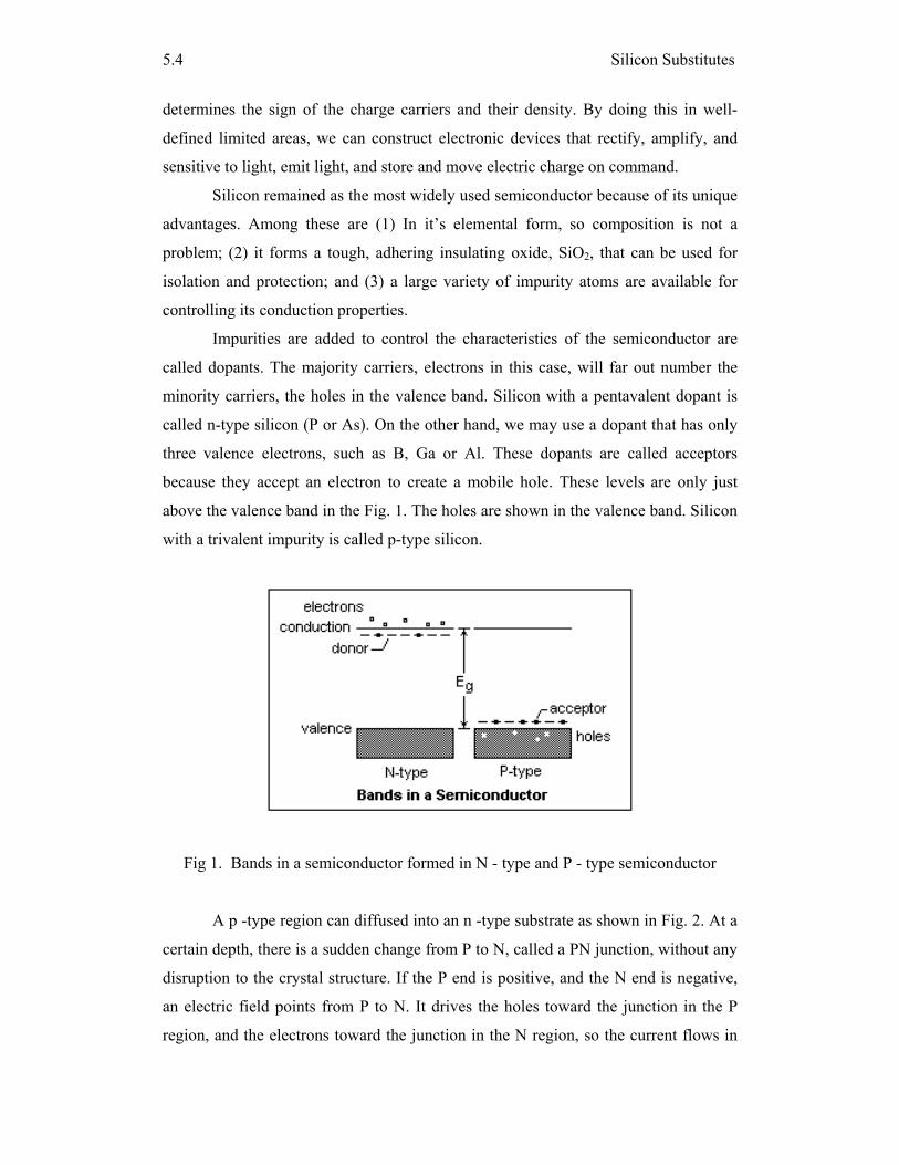
Silicon Substitutes
5.4
determines the sign of the charge carriers and their density. By doing this in well-
defined limited areas, we can construct electronic devices that rectify, amplify, and
sensitive to light, emit light, and store and move electric charge on command.
Silicon remained as the most widely used semiconductor because of its unique
advantages. Among these are (1) In it’s elemental form, so composition is not a
problem; (2) it forms a tough, adhering insulating oxide, SiO2, that can be used for
isolation and protection; and (3) a large variety of impurity atoms are available for
controlling its conduction properties.
Impurities are added to control the characteristics of the semiconductor are
called dopants. The majority carriers, electrons in this case, will far out number the
minority carriers, the holes in the valence band. Silicon with a pentavalent dopant is
called n-type silicon (P or As). On the other hand, we may use a dopant that has only
three valence electrons, such as B, Ga or Al. These dopants are called acceptors
because they accept an electron to create a mobile hole. These levels are only just
above the valence band in the Fig. 1. The holes are shown in the valence band. Silicon
with a trivalent impurity is called p-type silicon.
Fig 1. Bands in a semiconductor formed in N - type and P - type semiconductor
A p -type region can diffused into an n -type substrate as shown in Fig. 2. At a
certain depth, there is a sudden change from P to N, called a PN junction, without any
disruption to the crystal structure. If the P end is positive, and the N end is negative,
an electric field points from P to N. It drives the holes toward the junction in the P
region, and the electrons toward the junction in the N region, so the current flows in
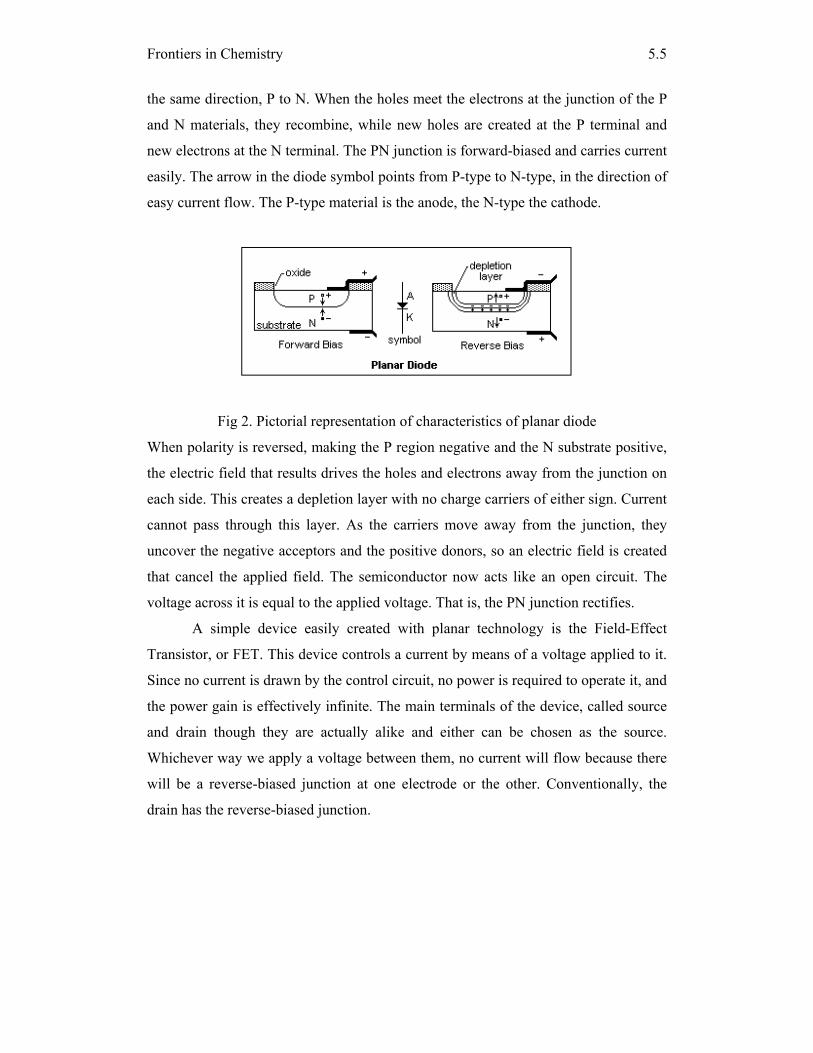
Frontiers in Chemistry
5.5
the same direction, P to N. When the holes meet the electrons at the junction of the P
and N materials, they recombine, while new holes are created at the P terminal and
new electrons at the N terminal. The PN junction is forward-biased and carries current
easily. The arrow in the diode symbol points from P-type to N-type, in the direction of
easy current flow. The P-type material is the anode, the N-type the cathode.
Fig 2. Pictorial representation of characteristics of planar diode
When polarity is reversed, making the P region negative and the N substrate positive,
the electric field that results drives the holes and electrons away from the junction on
each side. This creates a depletion layer with no charge carriers of either sign. Current
cannot pass through this layer. As the carriers move away from the junction, they
uncover the negative acceptors and the positive donors, so an electric field is created
that cancel the applied field. The semiconductor now acts like an open circuit. The
voltage across it is equal to the applied voltage. That is, the PN junction rectifies.
A simple device easily created with planar technology is the Field-Effect
Transistor, or FET. This device controls a current by means of a voltage applied to it.
Since no current is drawn by the control circuit, no power is required to operate it, and
the power gain is effectively infinite. The main terminals of the device, called source
and drain though they are actually alike and either can be chosen as the source.
Whichever way we apply a voltage between them, no current will flow because there
will be a reverse-biased junction at one electrode or the other. Conventionally, the
drain has the reverse-biased junction.
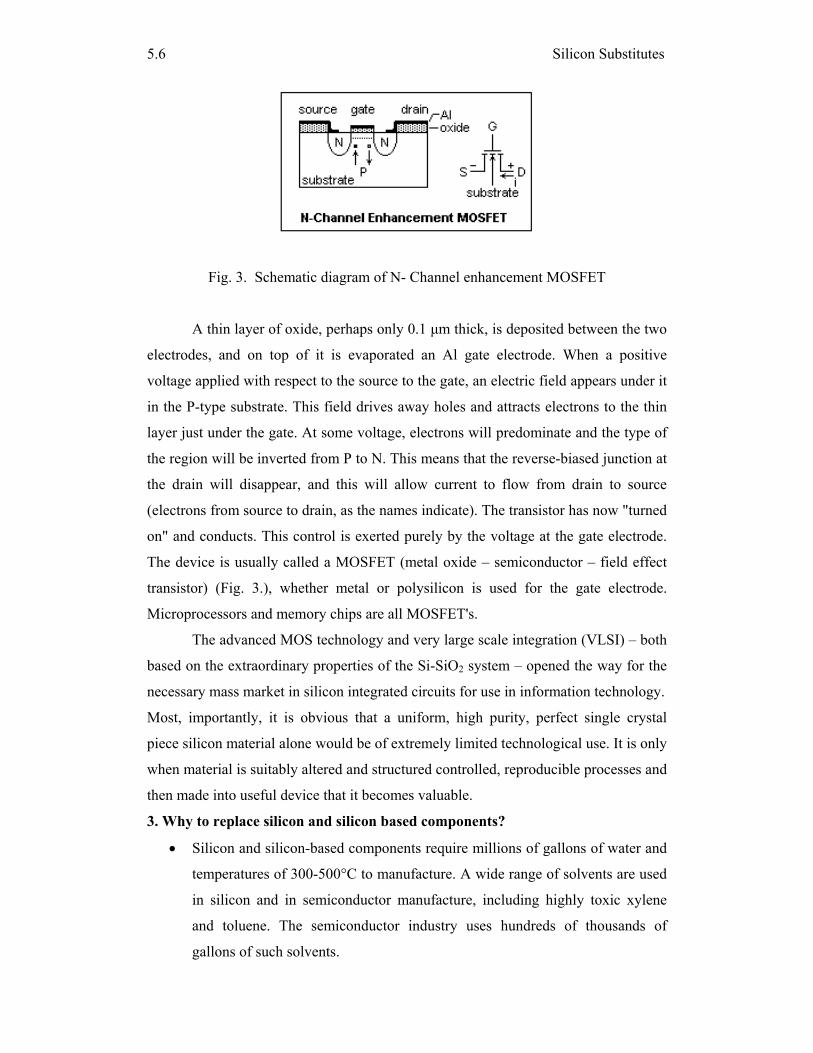
Silicon Substitutes
5.6
Fig. 3. Schematic diagram of N- Channel enhancement MOSFET
A thin layer of oxide, perhaps only 0.1 μm thick, is deposited between the two
electrodes, and on top of it is evaporated an Al gate electrode. When a positive
voltage applied with respect to the source to the gate, an electric field appears under it
in the P-type substrate. This field drives away holes and attracts electrons to the thin
layer just under the gate. At some voltage, electrons will predominate and the type of
the region will be inverted from P to N. This means that the reverse-biased junction at
the drain will disappear, and this will allow current to flow from drain to source
(electrons from source to drain, as the names indicate). The transistor has now "turned
on" and conducts. This control is exerted purely by the voltage at the gate electrode.
The device is usually called a MOSFET (metal oxide – semiconductor – field effect
transistor) (Fig. 3.), whether metal or polysilicon is used for the gate electrode.
Microprocessors and memory chips are all MOSFET's.
The advanced MOS technology and very large scale integration (VLSI) – both
based on the extraordinary properties of the Si-SiO2 system – opened the way for the
necessary mass market in silicon integrated circuits for use in information technology.
Most, importantly, it is obvious that a uniform, high purity, perfect single crystal
piece silicon material alone would be of extremely limited technological use. It is only
when material is suitably altered and structured controlled, reproducible processes and
then made into useful device that it becomes valuable.
3. Why to replace silicon and silicon based components?
• Silicon and silicon-based components require millions of gallons of water and
temperatures of 300-500°C to manufacture. A wide range of solvents are used
in silicon and in semiconductor manufacture, including highly toxic xylene
and toluene. The semiconductor industry uses hundreds of thousands of
gallons of such solvents.

Frontiers in Chemistry
5.7
• Silicon chips can malfunction at high temperatures, often from the heat
generated in their own circuitry.
• Conventional computer chips are made from a thin slice of silicon. This is
manufactured by cooling pure, molten silicon so that as it solidifies a crystal of
the material forms in a certain direction.
• Silicon wafers are then chemically "doped" with impurities to improve their
ability to carry an electrical charge.
• The types of impurities added affect the direction of the charge. However, the
weakness of devices based on silicon is their sensitivity to heat. This factor
requires fans or other gadgets to cool them down and limits their future
miniaturisation.
According to Moore’s law, which predicts a decrease in feature sizes by a factor of
0.7 every 3 years, silicon transistors have become smaller and smaller in order to
achieve higher intergration density, higher speed, lower power consumption and
lower cost. Many challenges have to be addressed for the making devices like,
lithography, metallization, power dissipation and circuit design. Focusing on the
device, the manadatory improvement in performance will be the key issue for further
downscaling. Therefore, novel architectures and new materials that would replace the
silicon are needed, to improve the electrical parameters further and thus pave the way
to much smaller transistors than those expected in the past.
4. Substitutes to silicon
Low-dimensional nanomaterials are of interest, since they exhibit highly anisotropic
or dimension-tunable properties, which are important attributes in nanodevice
applications. Recently, carbon nanotubes (CNTs) are promising low-dimensional
nanomaterials because of their interesting properties, such as small diameter, high
mechanical strength, high thermal and chemical stabilities, excellent heat conduction,
interesting electrical and electronic properties. CNTs can be either metallic or
semiconducting, with the semiconducting band gap depending upon the tube
diameter, geometry, and chirality. CNTs, composite materials like ceramics and
organic molecules are totally well-suited with the Si-based microelectronics. This
type of one dimensional material behaves as substitutes for silicon and silicon based
compounds.
Silicon Substitutes
5.8
Nanotubes belong to a promising group of nanostructured materials. Although other
nanotubes based on boron nitride and molybdenum have been reported, currently
carbon nanotubes are by far the most important group. The single-walled carbon
nanotubes are used in macroelectronic applications as compared to silicon and silicon
based materials. Carbon nanotubes offer extremely high field-effect mobilities, lower
operating voltages and better electronic characteristics while retaining the ability to be
placed onto a wide variety of substrates. The main technological issue is the
development of a reliable device fabrication methodology. Carbon nanotubes exhibit
favorable electronic properties compared to other materials that can be deposited on
large substrates. As a comparison to other electronic materials, effective electron
mobility is shown by Carbon nanotubes. This effective mobility is scaled by the
overall length and width of the active region on the device.
The important use of elemental silicon is as a semiconductor. Silicon is often
compared to carbon. Compared to similarities the difference between Si and C are
more significant.
• "What is so special about Carbon?"
• Is it the four valency of carbon?
• Is the ability to bond with another carbon atom?
• Is it the chiral nature of the bond?
• Is it the number of compounds that can be formed?
• Is it the tetrahedral orientation of the bonds?
• Is it the electronic configuration of the atom of carbon?
• Is it that carbon exists in a variety of allotropic modifications?
• Is it the position in the periodic table that makes it special?
• Is it that its atomic orbitals can give rise to multiple hybridizations?
• Is it that the atomic energy values of the orbitals of carbon have specificity?
• Is it that carbon is main constituent of all our energy resources?
4.1 Si versus C: what are the differences?
Carbon and silicon are the two most important elements in the Periodic Table for
obvious reasons. They occupy the central stage of the early rows of the Periodic Table
by being the first and the second members of Group IV. Carbon, unique in nature is
also the factor which differentiates these two elements. Despite the fact that silicon
and carbon both have four valence orbitals and four electrons, the two elements have
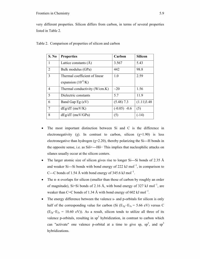
Frontiers in Chemistry
5.9
very different properties. Silicon differs from carbon, in terms of several properties
listed in Table 2.
Table 2. Comparison of properties of silicon and carbon
S. No Properties Carbon Silicon
1 Lattice constants (Å) 3.567 5.43
2 Bulk modulus (GPa) 442 98.8
3 Thermal coefficient of linear
expansion (10-6/K)
1.0 2.59
4 Thermal conductivity (W/cm.K) ~20 1.56
5 Dielectric constants 5.7 11.9
6 Band Gap Eg (eV) (5.48) 7.3 (1.11)3.48
7 dEg/dT (meV/K) (-0.05) -0.6 (5)
8 dEg/dT (meV/GPa) (5) (-14)
• The most important distinction between Si and C is the difference in
electronegativity (χ). In contrast to carbon, silicon (χ=1.90) is less
electronegative than hydrogen (χ=2.20), thereby polarizing the Si---H bonds in
the opposite sense, i.e. as Siδ+---Hδ− This implies that nucleophilic attacks on
silanes usually occur at the silicon centers.
• The larger atomic size of silicon gives rise to longer Si---Si bonds of 2.35 Å
and weaker Si---Si bonds with bond energy of 222 kJ mol−1, in comparison to
C---C bonds of 1.54 Å with bond energy of 345.6 kJ mol−1.
• The π–π overlaps for silicon (smaller than those of carbon by roughly an order
of magnitude), Si=Si bonds of 2.16 Å, with bond energy of 327 kJ mol−1, are
weaker than C=C bonds of 1.34 Å with bond energy of 602 kJ mol−1.
• The energy difference between the valence s- and p-orbitals for silicon is only
half of the corresponding value for carbon (Si (E3p−E3s = 5.66 eV) versus C
(E2p−E2s = 10.60 eV)). As a result, silicon tends to utilize all three of its
valence p-orbitals, resulting in sp3 hybridization, in contrast to carbon which
can "activate" one valence p-orbital at a time to give sp, sp2, and sp3
hybridizations.
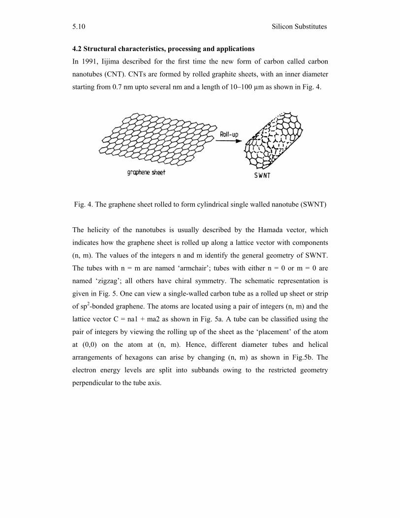
Silicon Substitutes
5.10
4.2 Structural characteristics, processing and applications
In 1991, Iijima described for the first time the new form of carbon called carbon
nanotubes (CNT). CNTs are formed by rolled graphite sheets, with an inner diameter
starting from 0.7 nm upto several nm and a length of 10–100 µm as shown in Fig. 4.
Fig. 4. The graphene sheet rolled to form cylindrical single walled nanotube (SWNT)
The helicity of the nanotubes is usually described by the Hamada vector, which
indicates how the graphene sheet is rolled up along a lattice vector with components
(n, m). The values of the integers n and m identify the general geometry of SWNT.
The tubes with n = m are named ‘armchair’; tubes with either n = 0 or m = 0 are
named ‘zigzag’; all others have chiral symmetry. The schematic representation is
given in Fig. 5. One can view a single-walled carbon tube as a rolled up sheet or strip
of sp2-bonded graphene. The atoms are located using a pair of integers (n, m) and the
lattice vector C = na1 + ma2 as shown in Fig. 5a. A tube can be classified using the
pair of integers by viewing the rolling up of the sheet as the ‘placement’ of the atom
at (0,0) on the atom at (n, m). Hence, different diameter tubes and helical
arrangements of hexagons can arise by changing (n, m) as shown in Fig.5b. The
electron energy levels are split into subbands owing to the restricted geometry
perpendicular to the tube axis.
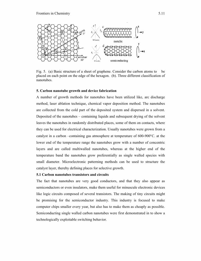
Frontiers in Chemistry
5.11
Fig. 5. (a) Basic structure of a sheet of graphene. Consider the carbon atoms to be placed on each point on the edge of the hexagon. (b). Three different classification of nanotubes.
5. Carbon nanotube growth and device fabrication
A number of growth methods for nanotubes have been utilized like, arc discharge
method, laser ablation technique, chemical vapor deposition method. The nanotubes
are collected from the cold part of the deposited system and dispersed in a solvent.
Deposited of the nanotubes – containing liquids and subsequent drying of the solvent
leaves the nanotubes in randomly distributed places, some of them on contacts, where
they can be used for electrical characterization. Usually nanotubes were grown from a
catalyst in a carbon –containing gas atmosphere at temperature of 600-900°C. at the
lower end of the temperature range the nanotubes grow with a number of concentric
layers and are called multiwalled nanotubes, whereas at the higher end of the
temperature band the nanotubes grow preferentially as single walled species with
small diameter. Microelectronic patterning methods can be used to structure the
catalyst layer, thereby defining places for selective growth.
5.1 Carbon nanotubes transistors and circuits
The fact that nanotubes are very good conductors, and that they also appear as
semiconductors or even insulators, make them useful for minuscule electronic devices
like logic circuits composed of several transistors. The making of tiny circuits might
be promising for the semiconductor industry. This industry is focused to make
computer chips smaller every year, but also has to make them as cheaply as possible.
Semiconducting single walled carbon nanotubes were first demonstrated in to show a
technologically exploitable switching behavior.
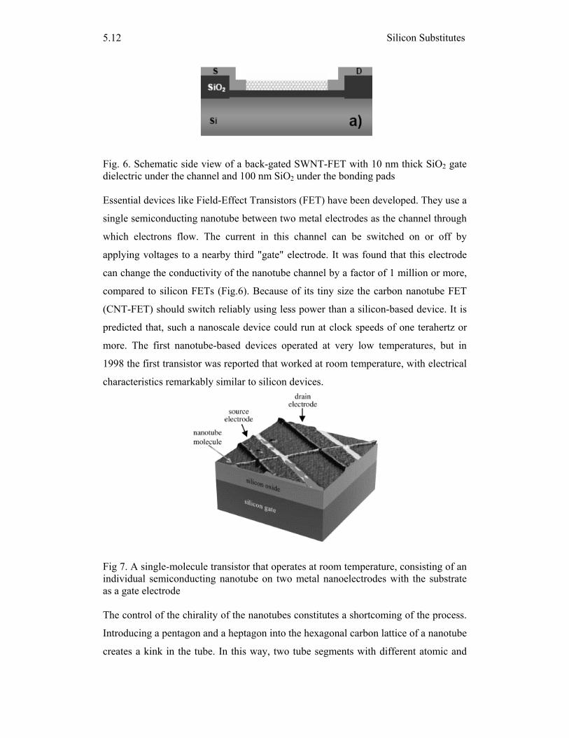
Silicon Substitutes
5.12
Fig. 6. Schematic side view of a back-gated SWNT-FET with 10 nm thick SiO2 gate dielectric under the channel and 100 nm SiO2 under the bonding pads Essential devices like Field-Effect Transistors (FET) have been developed. They use a
single semiconducting nanotube between two metal electrodes as the channel through
which electrons flow. The current in this channel can be switched on or off by
applying voltages to a nearby third "gate" electrode. It was found that this electrode
can change the conductivity of the nanotube channel by a factor of 1 million or more,
compared to silicon FETs (Fig.6). Because of its tiny size the carbon nanotube FET
(CNT-FET) should switch reliably using less power than a silicon-based device. It is
predicted that, such a nanoscale device could run at clock speeds of one terahertz or
more. The first nanotube-based devices operated at very low temperatures, but in
1998 the first transistor was reported that worked at room temperature, with electrical
characteristics remarkably similar to silicon devices.
Fig 7. A single-molecule transistor that operates at room temperature, consisting of an individual semiconducting nanotube on two metal nanoelectrodes with the substrate as a gate electrode The control of the chirality of the nanotubes constitutes a shortcoming of the process.
Introducing a pentagon and a heptagon into the hexagonal carbon lattice of a nanotube
creates a kink in the tube. In this way, two tube segments with different atomic and
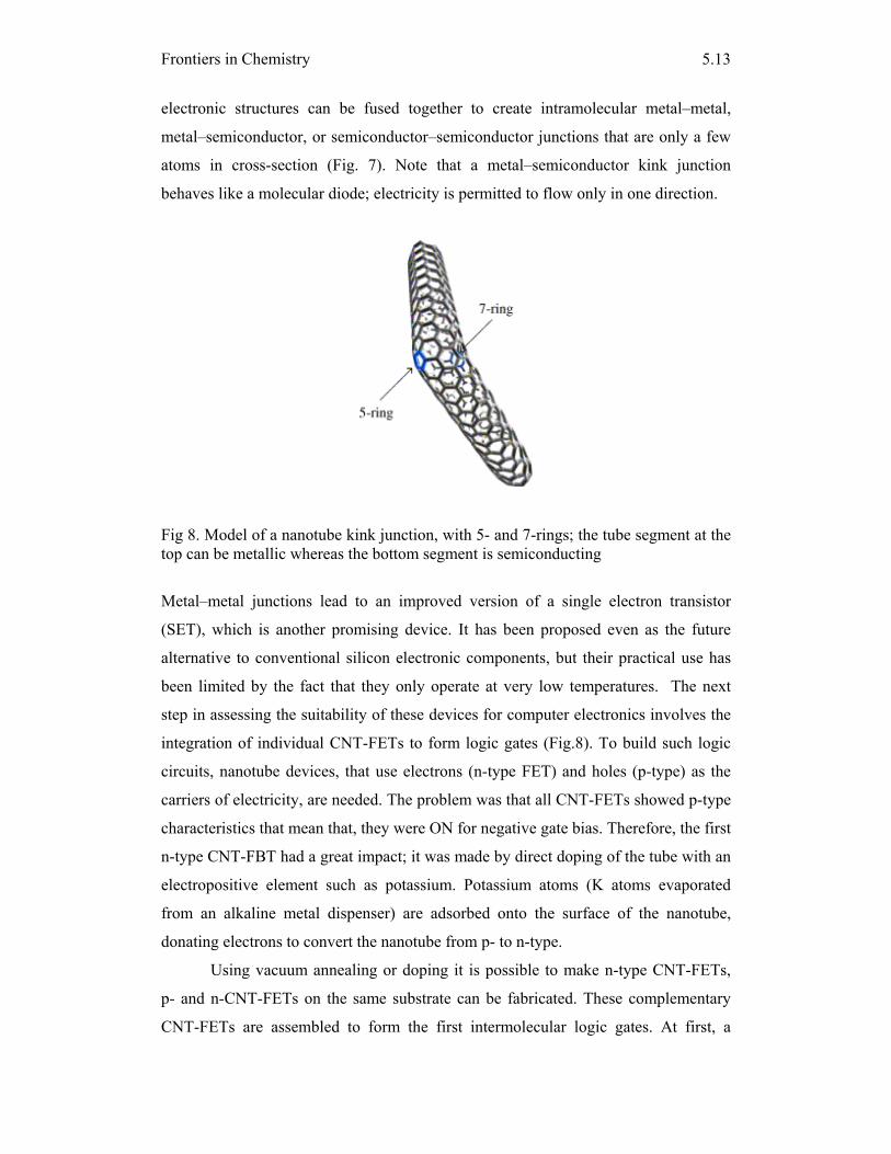
Frontiers in Chemistry
5.13
electronic structures can be fused together to create intramolecular metal–metal,
metal–semiconductor, or semiconductor–semiconductor junctions that are only a few
atoms in cross-section (Fig. 7). Note that a metal–semiconductor kink junction
behaves like a molecular diode; electricity is permitted to flow only in one direction.
Fig 8. Model of a nanotube kink junction, with 5- and 7-rings; the tube segment at the top can be metallic whereas the bottom segment is semiconducting
Metal–metal junctions lead to an improved version of a single electron transistor
(SET), which is another promising device. It has been proposed even as the future
alternative to conventional silicon electronic components, but their practical use has
been limited by the fact that they only operate at very low temperatures. The next
step in assessing the suitability of these devices for computer electronics involves the
integration of individual CNT-FETs to form logic gates (Fig.8). To build such logic
circuits, nanotube devices, that use electrons (n-type FET) and holes (p-type) as the
carriers of electricity, are needed. The problem was that all CNT-FETs showed p-type
characteristics that mean that, they were ON for negative gate bias. Therefore, the first
n-type CNT-FBT had a great impact; it was made by direct doping of the tube with an
electropositive element such as potassium. Potassium atoms (K atoms evaporated
from an alkaline metal dispenser) are adsorbed onto the surface of the nanotube,
donating electrons to convert the nanotube from p- to n-type.
Using vacuum annealing or doping it is possible to make n-type CNT-FETs,
p- and n-CNT-FETs on the same substrate can be fabricated. These complementary
CNT-FETs are assembled to form the first intermolecular logic gates. At first, a
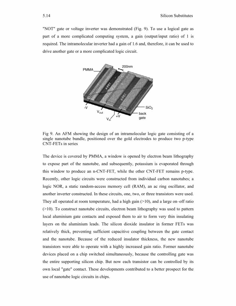
Silicon Substitutes
5.14
"NOT" gate or voltage inverter was demonstrated (Fig. 9). To use a logical gate as
part of a more complicated computing system, a gain (output/input ratio) of 1 is
required. The intramolecular inverter had a gain of 1.6 and, therefore, it can be used to
drive another gate or a more complicated logic circuit.
Fig 9. An AFM showing the design of an intramolecular logic gate consisting of a single nanotube bundle, positioned over the gold electrodes to produce two p-type CNT-FETs in series
The device is covered by PMMA, a window is opened by electron beam lithography
to expose part of the nanotube, and subsequently, potassium is evaporated through
this window to produce an n-CNT-FET, while the other CNT-FET remains p-type.
Recently, other logic circuits were constructed from individual carbon nanotubes; a
logic NOR, a static random-access memory cell (RAM), an ac ring oscillator, and
another inverter constructed. In these circuits, one, two, or three transistors were used.
They all operated at room temperature, had a high gain (>10), and a large on–off ratio
(>10). To construct nanotube circuits, electron beam lithography was used to pattern
local aluminium gate contacts and exposed them to air to form very thin insulating
layers on the aluminium leads. The silicon dioxide insulator in former FETs was
relatively thick, preventing sufficient capacitive coupling between the gate contact
and the nanotube. Because of the reduced insulator thickness, the new nanotube
transistors were able to operate with a highly increased gain ratio. Former nanotube
devices placed on a chip switched simultaneously, because the controlling gate was
the entire supporting silicon chip. But now each transistor can be controlled by its
own local "gate" contact. These developments contributed to a better prospect for the
use of nanotube logic circuits in chips.
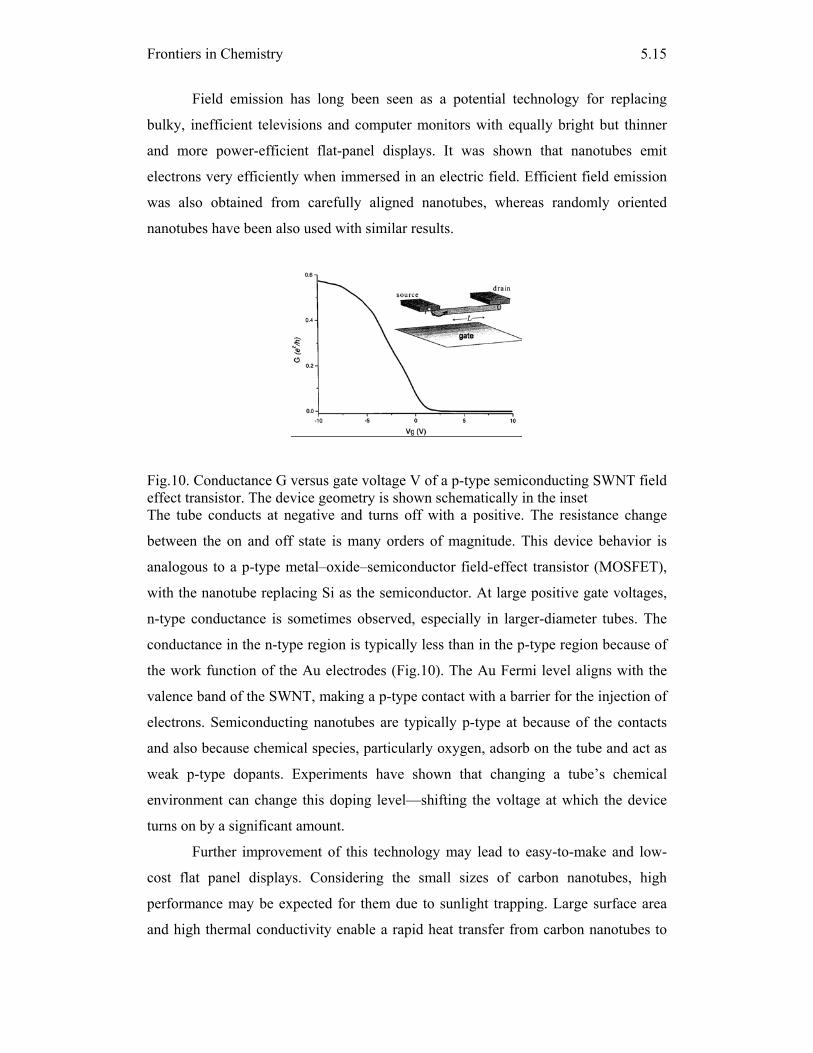
Frontiers in Chemistry
5.15
Field emission has long been seen as a potential technology for replacing
bulky, inefficient televisions and computer monitors with equally bright but thinner
and more power-efficient flat-panel displays. It was shown that nanotubes emit
electrons very efficiently when immersed in an electric field. Efficient field emission
was also obtained from carefully aligned nanotubes, whereas randomly oriented
nanotubes have been also used with similar results.
Fig.10. Conductance G versus gate voltage V of a p-type semiconducting SWNT field effect transistor. The device geometry is shown schematically in the inset The tube conducts at negative and turns off with a positive. The resistance change
between the on and off state is many orders of magnitude. This device behavior is
analogous to a p-type metal–oxide–semiconductor field-effect transistor (MOSFET),
with the nanotube replacing Si as the semiconductor. At large positive gate voltages,
n-type conductance is sometimes observed, especially in larger-diameter tubes. The
conductance in the n-type region is typically less than in the p-type region because of
the work function of the Au electrodes (Fig.10). The Au Fermi level aligns with the
valence band of the SWNT, making a p-type contact with a barrier for the injection of
electrons. Semiconducting nanotubes are typically p-type at because of the contacts
and also because chemical species, particularly oxygen, adsorb on the tube and act as
weak p-type dopants. Experiments have shown that changing a tube’s chemical
environment can change this doping level—shifting the voltage at which the device
turns on by a significant amount.
Further improvement of this technology may lead to easy-to-make and low-
cost flat panel displays. Considering the small sizes of carbon nanotubes, high
performance may be expected for them due to sunlight trapping. Large surface area
and high thermal conductivity enable a rapid heat transfer from carbon nanotubes to
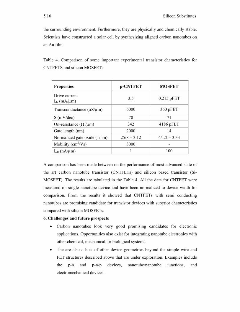
Silicon Substitutes
5.16
the surrounding environment. Furthermore, they are physically and chemically stable.
Scientists have constructed a solar cell by synthesizing aligned carbon nanotubes on
an Au film.
Table 4. Comparison of some important experimental transistor characteristics for
CNTFETS and silicon MOSFETs
Properties p-CNTFET MOSFET
Drive current Ids (mA/μm) 3.5 0.215 pFET
Transconductance (μS/μm) 6000 360 pFET
S (mV/dec) 70 71 On-resistance (Ω /μm) 342 4186 pFET Gate length (nm) 2000 14 Normalized gate oxide (1/nm) 25/8 = 3.12 4/1.2 = 3.33 Mobility (cm2/Vs) 3000 - Ioff (nA/μm) 1 100
A comparison has been made between on the performance of most advanced state of
the art carbon nanotube transistor (CNTFETs) and silicon based transistor (Si-
MOSFET). The results are tabulated in the Table 4. All the data for CNTFET were
measured on single nanotube device and have been normalized to device width for
comparison. From the results it showed that CNTFETs with semi conducting
nanotubes are promising candidate for transistor devices with superior characteristics
compared with silicon MOSFETs.
6. Challenges and future prospects
• Carbon nanotubes look very good promising candidates for electronic
applications. Opportunities also exist for integrating nanotube electronics with
other chemical, mechanical, or biological systems.
• The are also a host of other device geometries beyond the simple wire and
FET structures described above that are under exploration. Examples include
the p-n and p-n-p devices, nanotube/nanotube junctions, and
electromechanical devices.
Frontiers in Chemistry
5.17
• More challenging is the issue of device manufacturability. Although a great
deal of work has been done, the progress to date has been modest. For
example, in tube synthesis, the diameter of the tubes can be controlled, but not
the chirality. As a result, the tubes are a mixture of metal and semiconductors.
• In CVD, the general location for tube growth can be controlled by patterning
the catalyst material, but the number of tubes and their orientation relative to
the substrate are still not well defined. Furthermore, the high growth
temperature (900 C) for CVD tubes is incompatible with many other standard
Si processes.
• The alternative approach, depositing tubes on a substrate after growth, avoids
this high temperature issue but suffers from the chirality and positioning
limitations.
• To date, there are no reliable, rapid, and reproducible approaches to creating
complex arrays of nanotube devices. This manufacturing issue is by far the
most significant impediment to using nanotubes in electronics applications.
• While there has been significant fanfare around “circuits” made with
nanotubes, in reality the accomplishments to date are a far cry from anything
that would impress a device engineer or circuit designer. However, there
appear to be no fundamental barriers to the development of a technology.
7. Other silicon substitutes materials
7.1 Organic electronics: a cleaner substitute for silicon
Until recently, plastics--ubiquitous in most areas of modern life--had yet to make
inroads into the electronics industry; their molecular configuration made them non
conducive to electrical flow, limiting their uses to shells for computers and insulation
for wires. In recent year the plastic polymers can be manipulated so they may be
fashioned into transistors, conductors, and other electrical components. Such uses for
these carbon/hydrogen/oxygen-based polymers are the subject of the field of organic
electronics. A wide variety of potential applications, transistors, electronic circuits,
high-density energy storage devices, advanced emissive displays, and advanced
photovoltaics. The benefits of plastics are substantial--in many cases, they offer a
safer, cheaper, lighter alternative to silicon.
• Organic electronics involves a smaller set of hazardous compounds and materials
than more traditional semiconductor based technologies.
Silicon Substitutes
5.18
• It may be possible to design organics that are soluble in less harmful solvents.
Polymers also are lighter and can cost much less to manufacture than the silicon
substrate.
• Organic fabrication is compatible with plastic substrates, which means you can
use a very low-cost. Additionally, organics are good for large-area needs.
• For example, an organic photovoltaic cell could weigh 100 times less than a
silicon-based cell and silicon wafer is more expensive than a sheet of plastic.
• The polymers won't be replacing silicon in certain applications, such as computer
semiconductors, because silicon will always be significantly faster. However,
plastics can serve as a substitute in applications where silicon is either impractical
or too expensive to use, but this is a technology with great promise.
Organics would be ideal in the current technology of photovoltaic cells, most of
which now use silicon. The lightness of organic photovoltaics would make them
perfect for consumer applications such as recharging personal digital assistants, and
their low cost would suit them for power generation in remote villages in developing
countries.
7.2 Organic Photovoltaic Technology
Conventional solar cells convert light energy into electricity through the photovoltaic
effect on semiconductor material like crystalline silicon. Though effective, this
methodology of harnessing solar energy has its drawbacks in the form of high
manufacturing costs and prices, decreasing availability of sufficient amounts of
silicon, module assembly costs, rigidity of panels etc. To counter these factors, new
technologies have emerged that make use of technologies that use cost-effective raw
materials and processes. Research on developing organic-based solar cells started in
the 1970s. Organic solar cells are a potentially cost-effective option for utilizing solar
energy. The technology itself is in the process of development, and shows promise
because of its ease of use, diversity of applications and manufacturing process.
Organic technology solar cells are essentially based on the photosynthesis
process in plants. The absorption of light in organic cells is done by the ‘dye’ which
substitutes for the silicon in conventional cells. This light causes the dye molecules to
get excited and release electrons that are converted to electrical energy. The use of use
of chemicals called dyes for the conversion process has led to organic cells also being
known as “dye-sensitized solar cells.”
Frontiers in Chemistry
5.19
7.3 Can we replace silicon chips with biochips?
The present day computers store information on a thin wafer of silicon and the
information is processed in the computer by reading zero’s and one’s produced as
electrons passing through the switch represent one and the stoppage of electron flow
as ''zero''. However silicon can not hold enough information or process information
fast enough for such applications as artificial intelligence or robot vision.
In contrast a biochip can store more information and processes faster than the
present silicon chip. The biomolecule that can be used is bactiorhodopsin that can
work with the light at the speed of light faster than the flow of electrons through the
silicon chip. The green light causes protein to fold and the folded protein is read as
one. Where as the unfolded protein represents zero, Laser light are used to see the
configuration of protein.
7.4 New plastic resin finds home in electronics industry
The new biodegradable resin is made with polylactic acid (PLA) processed from
cornstarch. This is already used to make cups and blister packaging, as well as bottles,
carpet, shirts, films, and wraps. Using PLA to manufacture an electronic product.
Specifically, the resin will be employed in the body casing and some internal parts.
Carbon is stored in plant starches, which can be broken down into natural plant
sugars. The carbon and other elements in these natural sugars are then used to make
PLA, the Nature Works building block. The goal of industries is to make the
production and disposal of electronic products more sustainable. Developing bio-
derived and bio-degradable plastics for the electrical and electronic sector is being
undertaken.
References
1. H.F. Wolf, Silicon semiconductor data, Vol.9, Pergamon Press 1969
2. P.Sifferts and E. Krimmel, Silicon: Evolution and future of a technology, Springer
2004
3. J. W. Mintmire and C. T. White Physical Review Letters 81 (12) (1998) 2506
4. M. S. Dresselhaus, G. Dresselhaus, P. C. Eklund, Science of Fullerenes an Carbon
Nanotubes, Academic, San Diego, 1996
5. N. Hamada, S. Sawada, and A. Oshiyama, Phys. Rev. Lett. 68 (1992) 1579
6. A. Thess, R. Lee, P. Nikolaev, H. Dai, P. Petit, J. Robert, C. Xu, Y. H. Lee, S. G.
Kim, A. G. Rinzler, D. T. Colbert, G. E. Scuseria, D. Tománek, J. E. Fischer, and
R. E. Smalley, Science 273 (1996) 483

Silicon Substitutes
5.20
7. T.N. Jackson, Y.Y. Lin, D.J. Gundlach, H. Klauk, S.F. Nelson, Organic thin film
transistors, International Semiconductor Device Research Symposium
Proceedings: 409 (1997) 412
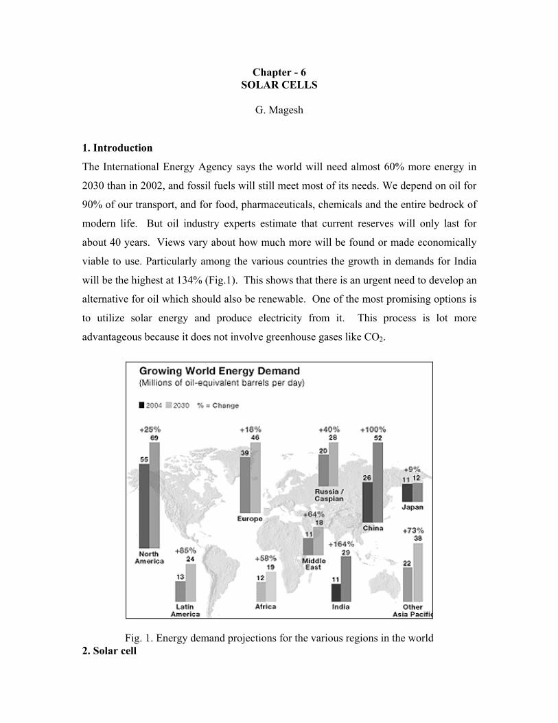
Chapter - 6 SOLAR CELLS
G. Magesh
1. Introduction
The International Energy Agency says the world will need almost 60% more energy in
2030 than in 2002, and fossil fuels will still meet most of its needs. We depend on oil for
90% of our transport, and for food, pharmaceuticals, chemicals and the entire bedrock of
modern life. But oil industry experts estimate that current reserves will only last for
about 40 years. Views vary about how much more will be found or made economically
viable to use. Particularly among the various countries the growth in demands for India
will be the highest at 134% (Fig.1). This shows that there is an urgent need to develop an
alternative for oil which should also be renewable. One of the most promising options is
to utilize solar energy and produce electricity from it. This process is lot more
advantageous because it does not involve greenhouse gases like CO2.
Fig. 1. Energy demand projections for the various regions in the world 2. Solar cell
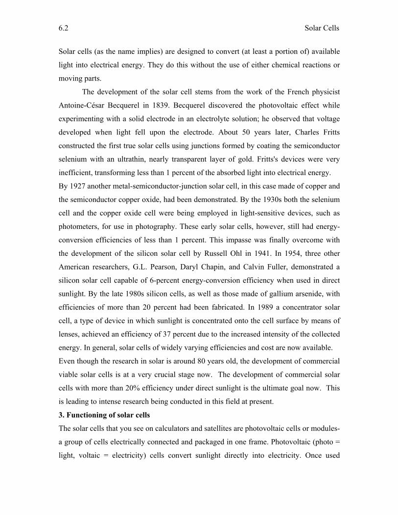
Solar Cells
6.2
Solar cells (as the name implies) are designed to convert (at least a portion of) available
light into electrical energy. They do this without the use of either chemical reactions or
moving parts.
The development of the solar cell stems from the work of the French physicist
Antoine-César Becquerel in 1839. Becquerel discovered the photovoltaic effect while
experimenting with a solid electrode in an electrolyte solution; he observed that voltage
developed when light fell upon the electrode. About 50 years later, Charles Fritts
constructed the first true solar cells using junctions formed by coating the semiconductor
selenium with an ultrathin, nearly transparent layer of gold. Fritts's devices were very
inefficient, transforming less than 1 percent of the absorbed light into electrical energy.
By 1927 another metal-semiconductor-junction solar cell, in this case made of copper and
the semiconductor copper oxide, had been demonstrated. By the 1930s both the selenium
cell and the copper oxide cell were being employed in light-sensitive devices, such as
photometers, for use in photography. These early solar cells, however, still had energy-
conversion efficiencies of less than 1 percent. This impasse was finally overcome with
the development of the silicon solar cell by Russell Ohl in 1941. In 1954, three other
American researchers, G.L. Pearson, Daryl Chapin, and Calvin Fuller, demonstrated a
silicon solar cell capable of 6-percent energy-conversion efficiency when used in direct
sunlight. By the late 1980s silicon cells, as well as those made of gallium arsenide, with
efficiencies of more than 20 percent had been fabricated. In 1989 a concentrator solar
cell, a type of device in which sunlight is concentrated onto the cell surface by means of
lenses, achieved an efficiency of 37 percent due to the increased intensity of the collected
energy. In general, solar cells of widely varying efficiencies and cost are now available.
Even though the research in solar is around 80 years old, the development of commercial
viable solar cells is at a very crucial stage now. The development of commercial solar
cells with more than 20% efficiency under direct sunlight is the ultimate goal now. This
is leading to intense research being conducted in this field at present.
3. Functioning of solar cells
The solar cells that you see on calculators and satellites are photovoltaic cells or modules-
a group of cells electrically connected and packaged in one frame. Photovoltaic (photo =
light, voltaic = electricity) cells convert sunlight directly into electricity. Once used
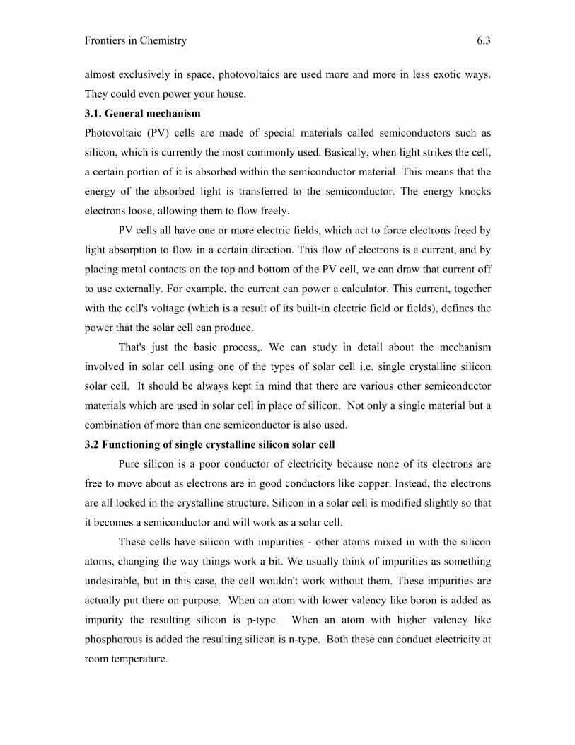
Frontiers in Chemistry
6.3
almost exclusively in space, photovoltaics are used more and more in less exotic ways.
They could even power your house.
3.1. General mechanism
Photovoltaic (PV) cells are made of special materials called semiconductors such as
silicon, which is currently the most commonly used. Basically, when light strikes the cell,
a certain portion of it is absorbed within the semiconductor material. This means that the
energy of the absorbed light is transferred to the semiconductor. The energy knocks
electrons loose, allowing them to flow freely.
PV cells all have one or more electric fields, which act to force electrons freed by
light absorption to flow in a certain direction. This flow of electrons is a current, and by
placing metal contacts on the top and bottom of the PV cell, we can draw that current off
to use externally. For example, the current can power a calculator. This current, together
with the cell's voltage (which is a result of its built-in electric field or fields), defines the
power that the solar cell can produce.
That's just the basic process,. We can study in detail about the mechanism
involved in solar cell using one of the types of solar cell i.e. single crystalline silicon
solar cell. It should be always kept in mind that there are various other semiconductor
materials which are used in solar cell in place of silicon. Not only a single material but a
combination of more than one semiconductor is also used.
3.2 Functioning of single crystalline silicon solar cell
Pure silicon is a poor conductor of electricity because none of its electrons are
free to move about as electrons are in good conductors like copper. Instead, the electrons
are all locked in the crystalline structure. Silicon in a solar cell is modified slightly so that
it becomes a semiconductor and will work as a solar cell.
These cells have silicon with impurities - other atoms mixed in with the silicon
atoms, changing the way things work a bit. We usually think of impurities as something
undesirable, but in this case, the cell wouldn't work without them. These impurities are
actually put there on purpose. When an atom with lower valency like boron is added as
impurity the resulting silicon is p-type. When an atom with higher valency like
phosphorous is added the resulting silicon is n-type. Both these can conduct electricity at
room temperature.
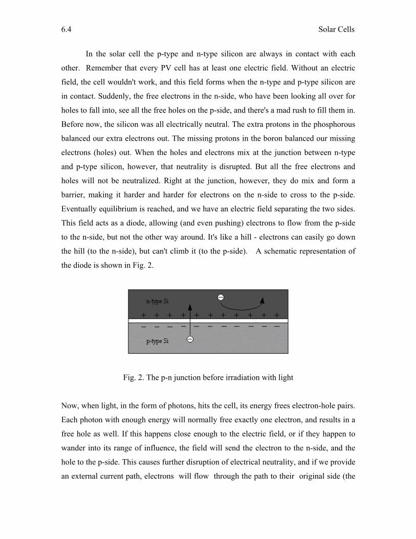
Solar Cells
6.4
In the solar cell the p-type and n-type silicon are always in contact with each
other. Remember that every PV cell has at least one electric field. Without an electric
field, the cell wouldn't work, and this field forms when the n-type and p-type silicon are
in contact. Suddenly, the free electrons in the n-side, who have been looking all over for
holes to fall into, see all the free holes on the p-side, and there's a mad rush to fill them in.
Before now, the silicon was all electrically neutral. The extra protons in the phosphorous
balanced our extra electrons out. The missing protons in the boron balanced our missing
electrons (holes) out. When the holes and electrons mix at the junction between n-type
and p-type silicon, however, that neutrality is disrupted. But all the free electrons and
holes will not be neutralized. Right at the junction, however, they do mix and form a
barrier, making it harder and harder for electrons on the n-side to cross to the p-side.
Eventually equilibrium is reached, and we have an electric field separating the two sides.
This field acts as a diode, allowing (and even pushing) electrons to flow from the p-side
to the n-side, but not the other way around. It's like a hill - electrons can easily go down
the hill (to the n-side), but can't climb it (to the p-side). A schematic representation of
the diode is shown in Fig. 2.
Fig. 2. The p-n junction before irradiation with light
Now, when light, in the form of photons, hits the cell, its energy frees electron-hole pairs.
Each photon with enough energy will normally free exactly one electron, and results in a
free hole as well. If this happens close enough to the electric field, or if they happen to
wander into its range of influence, the field will send the electron to the n-side, and the
hole to the p-side. This causes further disruption of electrical neutrality, and if we provide
an external current path, electrons will flow through the path to their original side (the
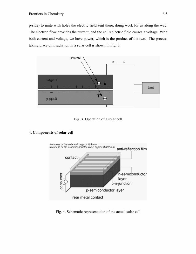
Frontiers in Chemistry
6.5
p-side) to unite with holes the electric field sent there, doing work for us along the way.
The electron flow provides the current, and the cell's electric field causes a voltage. With
both current and voltage, we have power, which is the product of the two. The process
taking place on irradiation in a solar cell is shown in Fig. 3.
Fig. 3. Operation of a solar cell
4. Components of solar cell
Fig. 4. Schematic representation of the actual solar cell

Solar Cells
6.6
In addition to the above mentioned semiconductor which is called as the absorber in
semiconductor technology. Fig. 4 shows the schematic of the actual solar cell. The
remaining components are explained further.
4.1. Electrical contacts
Electrical contacts are essential to a photovoltaic cell because they bridge the connection
between the semiconductor material and the external electrical load, such as a light bulb.
The back contact of a cell, i.e, on the side away from the incoming sunlight i.e is
relatively simple. It usually consists of a layer of aluminum or molybdenum metal. But
the front contact, on the side facing the sun, i.e is more complicated. When sunlight
shines on the photovoltaic cell, a current of electrons flows all over its surface. If we
attach contacts only at the edges of the cell, it will not work well because of the great
electrical resistance of the top semiconductor layer. Only a small number of electrons
would make it to the contact.
To collect the maximum current, one must place contacts across the entire surface
of a photovoltaic cell. This is normally done with a "grid" of metal strips or "fingers."
However, placing a large grid, which is opaque, on the top of the cell shades active parts
of the cell from the sun. The cell's conversion efficiency is thus significantly reduced. To
improve the conversion efficiency, we must minimize these shading effects. Another
challenge in cell design is to minimize the electrical resistance losses when applying grid
contacts to the solar cell material. These losses are related to the solar cell material's
property of opposing the flow of an electric current, which results in heating the material.
Therefore, in designing grid contacts, we must balance shading effects against electrical
resistance losses. The usual approach is to design grids with many thin, conductive
fingers spreading to every part of the cell's surface. The fingers of the grid must be thick
enough to conduct well (with low resistance), but thin enough not to block much of the
incoming light. This kind of grid keeps resistance losses low while shading only about
3% to 5% of the cell's surface.
Grids can be expensive to make and can affect the cell's reliability. To make top-
surface grids, we can either deposit metallic vapors on a cell through a mask or paint
them on via a screen-printing method. Photolithography is the preferred method for the
highest quality, but has the greatest cost. This process involves transferring an image via
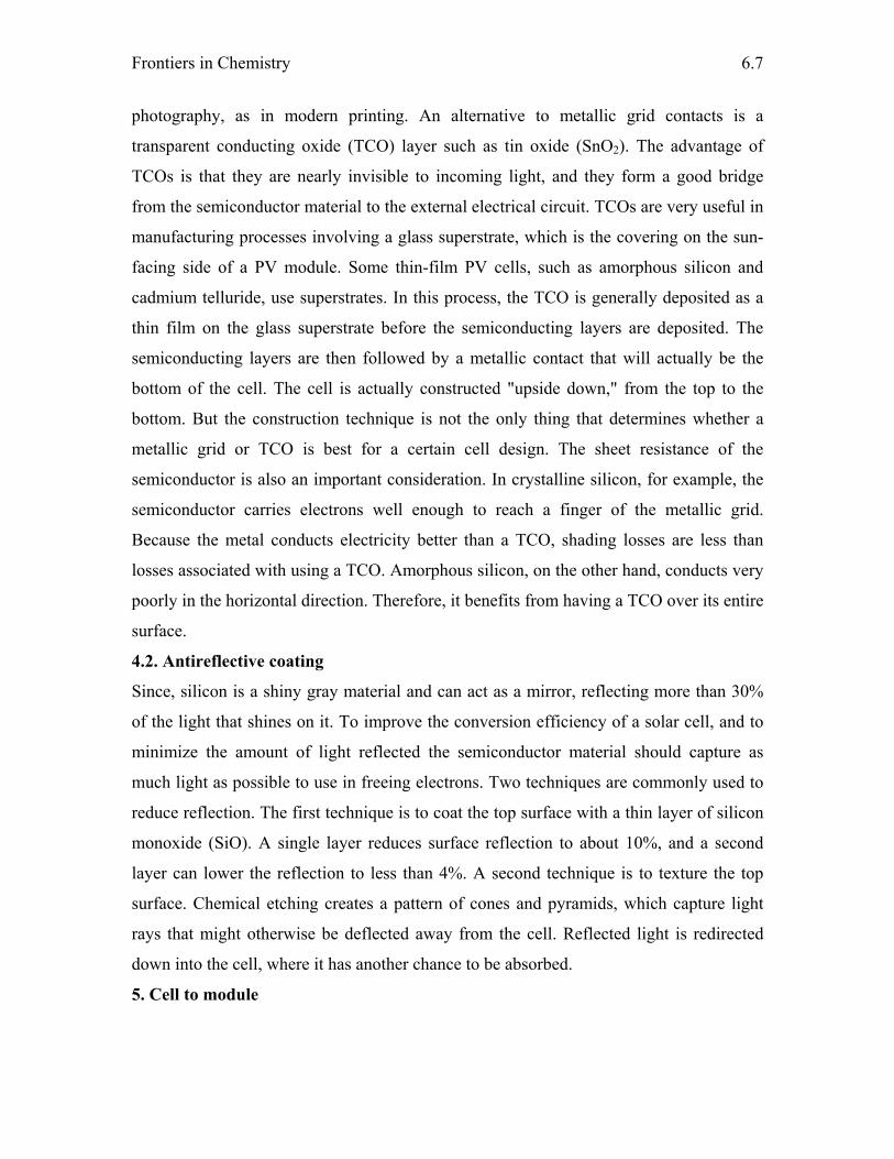
Frontiers in Chemistry
6.7
photography, as in modern printing. An alternative to metallic grid contacts is a
transparent conducting oxide (TCO) layer such as tin oxide (SnO2). The advantage of
TCOs is that they are nearly invisible to incoming light, and they form a good bridge
from the semiconductor material to the external electrical circuit. TCOs are very useful in
manufacturing processes involving a glass superstrate, which is the covering on the sun-
facing side of a PV module. Some thin-film PV cells, such as amorphous silicon and
cadmium telluride, use superstrates. In this process, the TCO is generally deposited as a
thin film on the glass superstrate before the semiconducting layers are deposited. The
semiconducting layers are then followed by a metallic contact that will actually be the
bottom of the cell. The cell is actually constructed "upside down," from the top to the
bottom. But the construction technique is not the only thing that determines whether a
metallic grid or TCO is best for a certain cell design. The sheet resistance of the
semiconductor is also an important consideration. In crystalline silicon, for example, the
semiconductor carries electrons well enough to reach a finger of the metallic grid.
Because the metal conducts electricity better than a TCO, shading losses are less than
losses associated with using a TCO. Amorphous silicon, on the other hand, conducts very
poorly in the horizontal direction. Therefore, it benefits from having a TCO over its entire
surface.
4.2. Antireflective coating
Since, silicon is a shiny gray material and can act as a mirror, reflecting more than 30%
of the light that shines on it. To improve the conversion efficiency of a solar cell, and to
minimize the amount of light reflected the semiconductor material should capture as
much light as possible to use in freeing electrons. Two techniques are commonly used to
reduce reflection. The first technique is to coat the top surface with a thin layer of silicon
monoxide (SiO). A single layer reduces surface reflection to about 10%, and a second
layer can lower the reflection to less than 4%. A second technique is to texture the top
surface. Chemical etching creates a pattern of cones and pyramids, which capture light
rays that might otherwise be deflected away from the cell. Reflected light is redirected
down into the cell, where it has another chance to be absorbed.
5. Cell to module
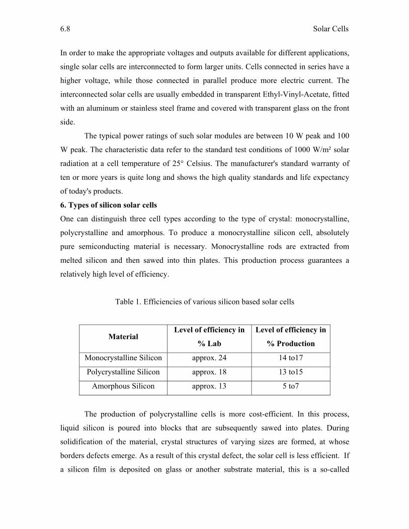
Solar Cells
6.8
In order to make the appropriate voltages and outputs available for different applications,
single solar cells are interconnected to form larger units. Cells connected in series have a
higher voltage, while those connected in parallel produce more electric current. The
interconnected solar cells are usually embedded in transparent Ethyl-Vinyl-Acetate, fitted
with an aluminum or stainless steel frame and covered with transparent glass on the front
side.
The typical power ratings of such solar modules are between 10 W peak and 100
W peak. The characteristic data refer to the standard test conditions of 1000 W/m² solar
radiation at a cell temperature of 25° Celsius. The manufacturer's standard warranty of
ten or more years is quite long and shows the high quality standards and life expectancy
of today's products.
6. Types of silicon solar cells
One can distinguish three cell types according to the type of crystal: monocrystalline,
polycrystalline and amorphous. To produce a monocrystalline silicon cell, absolutely
pure semiconducting material is necessary. Monocrystalline rods are extracted from
melted silicon and then sawed into thin plates. This production process guarantees a
relatively high level of efficiency.
Table 1. Efficiencies of various silicon based solar cells
Material Level of efficiency in
% Lab
Level of efficiency in
% Production
Monocrystalline Silicon approx. 24 14 to17
Polycrystalline Silicon approx. 18 13 to15
Amorphous Silicon approx. 13 5 to7
The production of polycrystalline cells is more cost-efficient. In this process,
liquid silicon is poured into blocks that are subsequently sawed into plates. During
solidification of the material, crystal structures of varying sizes are formed, at whose
borders defects emerge. As a result of this crystal defect, the solar cell is less efficient. If
a silicon film is deposited on glass or another substrate material, this is a so-called
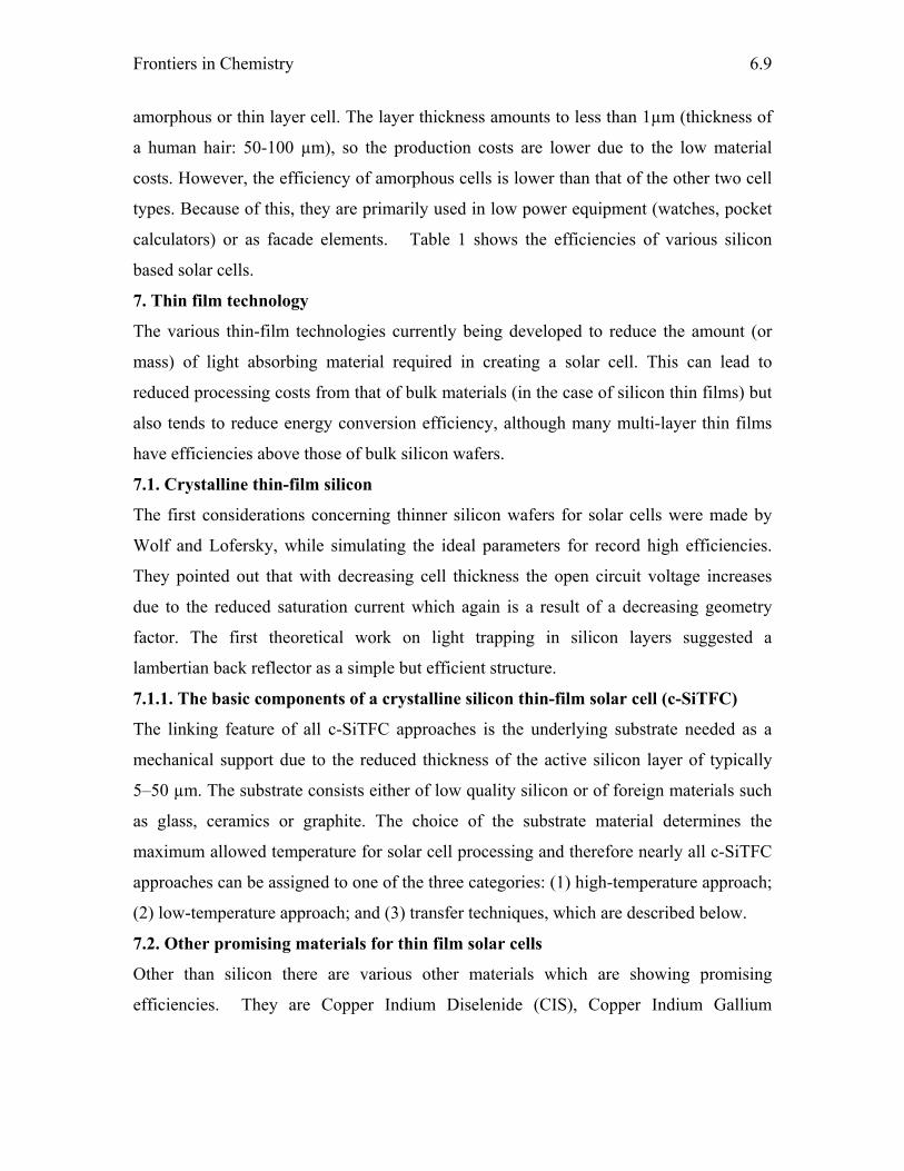
Frontiers in Chemistry
6.9
amorphous or thin layer cell. The layer thickness amounts to less than 1µm (thickness of
a human hair: 50-100 µm), so the production costs are lower due to the low material
costs. However, the efficiency of amorphous cells is lower than that of the other two cell
types. Because of this, they are primarily used in low power equipment (watches, pocket
calculators) or as facade elements. Table 1 shows the efficiencies of various silicon
based solar cells.
7. Thin film technology
The various thin-film technologies currently being developed to reduce the amount (or
mass) of light absorbing material required in creating a solar cell. This can lead to
reduced processing costs from that of bulk materials (in the case of silicon thin films) but
also tends to reduce energy conversion efficiency, although many multi-layer thin films
have efficiencies above those of bulk silicon wafers.
7.1. Crystalline thin-film silicon
The first considerations concerning thinner silicon wafers for solar cells were made by
Wolf and Lofersky, while simulating the ideal parameters for record high efficiencies.
They pointed out that with decreasing cell thickness the open circuit voltage increases
due to the reduced saturation current which again is a result of a decreasing geometry
factor. The first theoretical work on light trapping in silicon layers suggested a
lambertian back reflector as a simple but efficient structure.
7.1.1. The basic components of a crystalline silicon thin-film solar cell (c-SiTFC)
The linking feature of all c-SiTFC approaches is the underlying substrate needed as a
mechanical support due to the reduced thickness of the active silicon layer of typically
5–50 µm. The substrate consists either of low quality silicon or of foreign materials such
as glass, ceramics or graphite. The choice of the substrate material determines the
maximum allowed temperature for solar cell processing and therefore nearly all c-SiTFC
approaches can be assigned to one of the three categories: (1) high-temperature approach;
(2) low-temperature approach; and (3) transfer techniques, which are described below.
7.2. Other promising materials for thin film solar cells
Other than silicon there are various other materials which are showing promising
efficiencies. They are Copper Indium Diselenide (CIS), Copper Indium Gallium
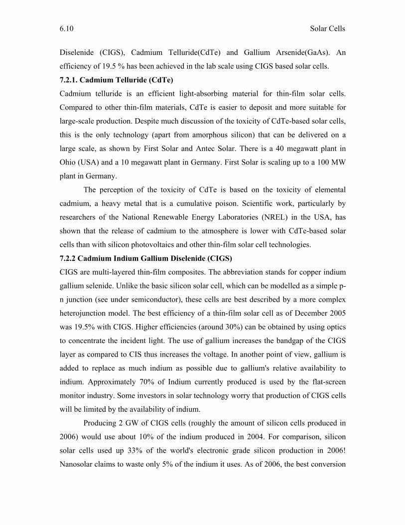
Solar Cells
6.10
Diselenide (CIGS), Cadmium Telluride(CdTe) and Gallium Arsenide(GaAs). An
efficiency of 19.5 % has been achieved in the lab scale using CIGS based solar cells.
7.2.1. Cadmium Telluride (CdTe)
Cadmium telluride is an efficient light-absorbing material for thin-film solar cells.
Compared to other thin-film materials, CdTe is easier to deposit and more suitable for
large-scale production. Despite much discussion of the toxicity of CdTe-based solar cells,
this is the only technology (apart from amorphous silicon) that can be delivered on a
large scale, as shown by First Solar and Antec Solar. There is a 40 megawatt plant in
Ohio (USA) and a 10 megawatt plant in Germany. First Solar is scaling up to a 100 MW
plant in Germany.
The perception of the toxicity of CdTe is based on the toxicity of elemental
cadmium, a heavy metal that is a cumulative poison. Scientific work, particularly by
researchers of the National Renewable Energy Laboratories (NREL) in the USA, has
shown that the release of cadmium to the atmosphere is lower with CdTe-based solar
cells than with silicon photovoltaics and other thin-film solar cell technologies.
7.2.2 Cadmium Indium Gallium Diselenide (CIGS)
CIGS are multi-layered thin-film composites. The abbreviation stands for copper indium
gallium selenide. Unlike the basic silicon solar cell, which can be modelled as a simple p-
n junction (see under semiconductor), these cells are best described by a more complex
heterojunction model. The best efficiency of a thin-film solar cell as of December 2005
was 19.5% with CIGS. Higher efficiencies (around 30%) can be obtained by using optics
to concentrate the incident light. The use of gallium increases the bandgap of the CIGS
layer as compared to CIS thus increases the voltage. In another point of view, gallium is
added to replace as much indium as possible due to gallium's relative availability to
indium. Approximately 70% of Indium currently produced is used by the flat-screen
monitor industry. Some investors in solar technology worry that production of CIGS cells
will be limited by the availability of indium.
Producing 2 GW of CIGS cells (roughly the amount of silicon cells produced in
2006) would use about 10% of the indium produced in 2004. For comparison, silicon
solar cells used up 33% of the world's electronic grade silicon production in 2006!
Nanosolar claims to waste only 5% of the indium it uses. As of 2006, the best conversion
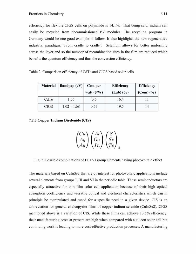
Frontiers in Chemistry
6.11
efficiency for flexible CIGS cells on polyimide is 14.1%. That being said, indium can
easily be recycled from decommissioned PV modules. The recycling program in
Germany would be one good example to follow. It also highlights the new regenerative
industrial paradigm: "From cradle to cradle". Selenium allows for better uniformity
across the layer and so the number of recombination sites in the film are reduced which
benefits the quantum efficiency and thus the conversion efficiency.
Table 2. Comparison efficiency of CdTe and CIGS based solar cells
Material Bandgap (eV) Cost per
watt ($/W)
Efficiency
(Lab) (%)
Efficiency
(Com) (%)
CdTe 1.56 0.6 16.4 11
CIGS 1.02 – 1.68 0.57 19.5 14
7.2.3 Copper Indium Diselenide (CIS)
Fig. 5. Possible combinations of I III VI group elements having photovoltaic effect
The materials based on CuInSe2 that are of interest for photovoltaic applications include
several elements from groups I, III and VI in the periodic table. These semiconductors are
especially attractive for thin film solar cell application because of their high optical
absorption coefficiency and versatile optical and electrical characteristics which can in
principle be manipulated and tuned for a specific need in a given device. CIS is an
abbreviation for general chalcopyrite films of copper indium selenide (CuInSe2), CIGS
mentioned above is a variation of CIS. While these films can achieve 13.5% efficiency,
their manufacturing costs at present are high when compared with a silicon solar cell but
continuing work is leading to more cost-effective production processes. A manufacturing
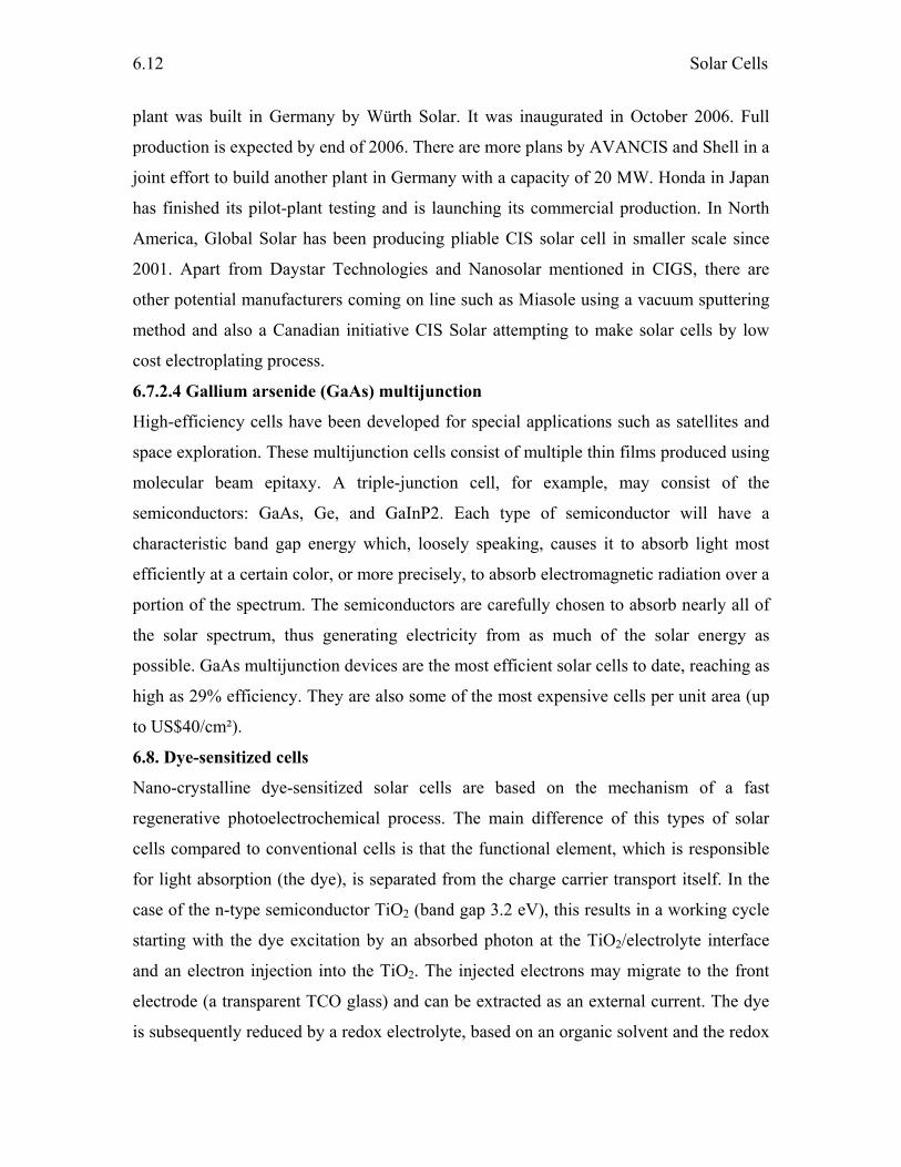
Solar Cells
6.12
plant was built in Germany by Würth Solar. It was inaugurated in October 2006. Full
production is expected by end of 2006. There are more plans by AVANCIS and Shell in a
joint effort to build another plant in Germany with a capacity of 20 MW. Honda in Japan
has finished its pilot-plant testing and is launching its commercial production. In North
America, Global Solar has been producing pliable CIS solar cell in smaller scale since
2001. Apart from Daystar Technologies and Nanosolar mentioned in CIGS, there are
other potential manufacturers coming on line such as Miasole using a vacuum sputtering
method and also a Canadian initiative CIS Solar attempting to make solar cells by low
cost electroplating process.
6.7.2.4 Gallium arsenide (GaAs) multijunction
High-efficiency cells have been developed for special applications such as satellites and
space exploration. These multijunction cells consist of multiple thin films produced using
molecular beam epitaxy. A triple-junction cell, for example, may consist of the
semiconductors: GaAs, Ge, and GaInP2. Each type of semiconductor will have a
characteristic band gap energy which, loosely speaking, causes it to absorb light most
efficiently at a certain color, or more precisely, to absorb electromagnetic radiation over a
portion of the spectrum. The semiconductors are carefully chosen to absorb nearly all of
the solar spectrum, thus generating electricity from as much of the solar energy as
possible. GaAs multijunction devices are the most efficient solar cells to date, reaching as
high as 29% efficiency. They are also some of the most expensive cells per unit area (up
to US$40/cm²).
6.8. Dye-sensitized cells
Nano-crystalline dye-sensitized solar cells are based on the mechanism of a fast
regenerative photoelectrochemical process. The main difference of this types of solar
cells compared to conventional cells is that the functional element, which is responsible
for light absorption (the dye), is separated from the charge carrier transport itself. In the
case of the n-type semiconductor TiO2 (band gap 3.2 eV), this results in a working cycle
starting with the dye excitation by an absorbed photon at the TiO2/electrolyte interface
and an electron injection into the TiO2. The injected electrons may migrate to the front
electrode (a transparent TCO glass) and can be extracted as an external current. The dye
is subsequently reduced by a redox electrolyte, based on an organic solvent and the redox
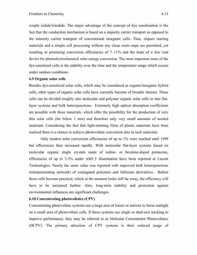
Frontiers in Chemistry
6.13
couple iodide/triiodide. The major advantage of the concept of dye sensitization is the
fact that the conduction mechanism is based on a majority carrier transport as opposed to
the minority carrier transport of conventional inorganic cells. Thus, impure starting
materials and a simple cell processing without any clean room steps are permitted, yet
resulting in promising conversion efficiencies of 7–11% and the hope of a low cost
device for photoelectrochemical solar energy conversion. The most important issue of the
dye-sensitized cells is the stability over the time and the temperature range which occurs
under outdoor conditions.
6.9 Organic solar cells
Besides dye-sensitized solar cells, which may be considered as organic/inorganic hybrid
cells, other types of organic solar cells have currently become of broader interest. These
cells can be divided roughly into molecular and polymer organic solar cells or into flat-
layer systems and bulk heterojunctions. Extremely high optical absorption coefficients
are possible with these materials, which offer the possibility for the production of very
thin solar cells (far below 1 mm) and therefore only very small amounts of needed
materials. Considering the fact that light-emitting films of plastic materials have been
realized there is a chance to achieve photovoltaic conversion also in such materials.
Only modest solar conversion efficiencies of up to 1% were reached until 1999
but efficiencies then increased rapidly. With molecular flat-layer systems based on
molecular organic single crystals made of iodine- or bromine-doped pentacene,
efficiencies of up to 3.3% under AM1.5 illumination have been reported at Lucent
Technologies. Nearly the same value was reported with improved bulk heterojunctions
(interpenetrating network) of conjugated polymers and fullerene derivatives. Before
these cells become practical, which at the moment looks still far away, the efficiency will
have to be increased further. Also, long-term stability and protection against
environmental influences are significant challenges.
6.10 Concentrating photovoltaics (CPV)
Concentrating photovoltaic systems use a large area of lenses or mirrors to focus sunlight
on a small area of photovoltaic cells. If these systems use single or dual-axis tracking to
improve performance, they may be referred to as Heliostat Concentrator Photovoltaics
(HCPV). The primary attraction of CPV systems is their reduced usage of
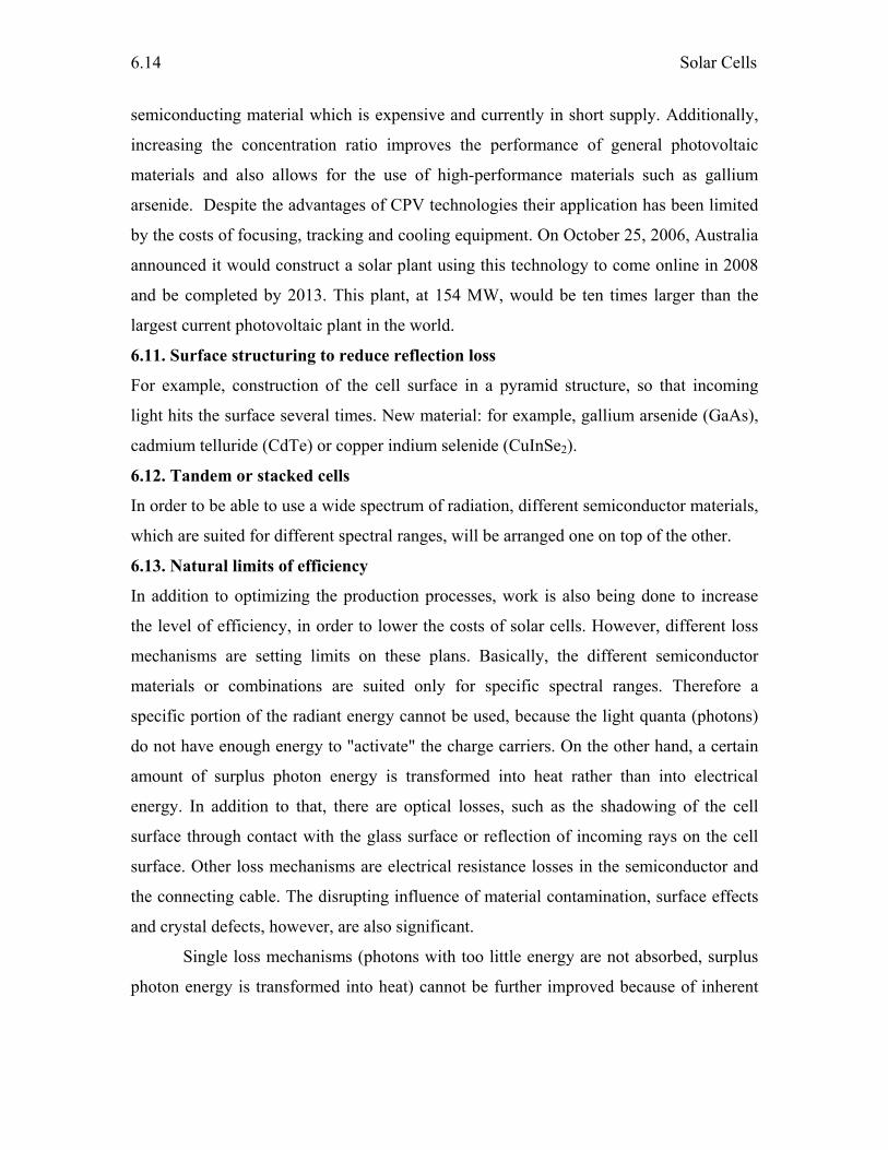
Solar Cells
6.14
semiconducting material which is expensive and currently in short supply. Additionally,
increasing the concentration ratio improves the performance of general photovoltaic
materials and also allows for the use of high-performance materials such as gallium
arsenide. Despite the advantages of CPV technologies their application has been limited
by the costs of focusing, tracking and cooling equipment. On October 25, 2006, Australia
announced it would construct a solar plant using this technology to come online in 2008
and be completed by 2013. This plant, at 154 MW, would be ten times larger than the
largest current photovoltaic plant in the world.
6.11. Surface structuring to reduce reflection loss
For example, construction of the cell surface in a pyramid structure, so that incoming
light hits the surface several times. New material: for example, gallium arsenide (GaAs),
cadmium telluride (CdTe) or copper indium selenide (CuInSe2).
6.12. Tandem or stacked cells
In order to be able to use a wide spectrum of radiation, different semiconductor materials,
which are suited for different spectral ranges, will be arranged one on top of the other.
6.13. Natural limits of efficiency
In addition to optimizing the production processes, work is also being done to increase
the level of efficiency, in order to lower the costs of solar cells. However, different loss
mechanisms are setting limits on these plans. Basically, the different semiconductor
materials or combinations are suited only for specific spectral ranges. Therefore a
specific portion of the radiant energy cannot be used, because the light quanta (photons)
do not have enough energy to "activate" the charge carriers. On the other hand, a certain
amount of surplus photon energy is transformed into heat rather than into electrical
energy. In addition to that, there are optical losses, such as the shadowing of the cell
surface through contact with the glass surface or reflection of incoming rays on the cell
surface. Other loss mechanisms are electrical resistance losses in the semiconductor and
the connecting cable. The disrupting influence of material contamination, surface effects
and crystal defects, however, are also significant.
Single loss mechanisms (photons with too little energy are not absorbed, surplus
photon energy is transformed into heat) cannot be further improved because of inherent

Frontiers in Chemistry
6.15
physical limits imposed by the materials themselves. This leads to a theoretical maximum
level of efficiency, i.e. approximately 28% for crystal silicon.
15. References
1. A. Goetzberger, J. Luther, G. Willeke, Sol. Energy Mater. Sol. Cells, 74 (2002) 1
2. A. L. Fahrenbruch, R.H. Bube, “Fundamentals of solar cells” Academic press,
London, 1983
3. K.L. Chopra, S.R. Das, “Thin film solar cells” Plenum press, New York, 1983
4. K. Ramanathan, M. A. Contreras, C. L. Perkins, S. Asher, F. S. Hasoon, J. Keane,
D. Young, M. Romero, W. Metzger, R. Noufi, J.Ward, A. Duda, Prog. Photovol: Res.
Appl, 11 (2003) 225
5. M. A. Contreras, B. Egaas, K. Ramanathan, J. Hiltner, A. Swartzlander, F. Hasoon,
R. Noufi, Prog. Photovol: Res. Appl, 7 (1999) 311

Chapter 7 IONIC LIQUIDS
C. M. Janet
1. Introduction An ionic liquid (IL) is a recently emerged new class of solvents which often exist as fluid
at room temperature. They consist entirely of ionic species. In a broad sense, the term
includes all molten salts, for instance, sodium chloride at temperatures higher than 800
°C. Today, however, the term "ionic liquid" is commonly used for salts whose melting
point is relatively low (below 100 °C). In particular, the salts that are liquid at room
temperature are called room-temperature ionic liquids or RTILs. They have many
fascinating properties which make them of fundamental interest to all chemists, since
both the thermodynamics and the kinetics of reactions carried out in ionic liquids are
different to those that take place in conventional molecular solvents and also the
chemistry is different and unpredictable at our current state of knowledge.
Designing of IL can be done by varying two components, they are anions and
cations. Either the solvents can be designed with a particular end use in mind or to
possess a particular set of properties. Hence the term designer solvents have been
assigned to the ionic liquids.
The first room-temperature ionic liquid [EtNH3][NO3] (m.pt. 12 °C) was
discovered in 1914 , but interest did not develop until the discovery of binary ionic
liquids made from mixtures of aluminum (III) chloride and N-alkylpyridinium or 1, 3
dialkylimidazolium chloride. In general, ionic liquids consist of a salt where one or both
the ions are large, and the cation has a low degree of symmetry. These factors tend to
reduce the lattice energy of the crystalline form of the salt and hence the melting point
will be lower. Ionic liquids come in two main categories, namely simple salts (made of a
single anion and cation) and binary ionic liquids (salts where equilibrium is involved).
For example, [EtNH3][NO3] is a simple salt whereas mixtures of aluminum (III) chloride
and 1,3-dialkylimidazolium chlorides (a binary ionic liquid system) contain several
different ionic species.

Ionic Liquids
7.2
Being advantageous over conventional organic solvents, ILs have attractive
physicochemical properties such as negligible vapor pressure even at elevated
temperatures, excellent thermal and chemical stability, high ionic conductivity up to 0.1 S
cm-1, high mobility, high heat capacity, cohesive energy density, low toxicity and non-
flammability. Furthermore, as the physicochemical properties of ILs strongly depend on
the species of cation and anion and the length of the lateral alkyl groups on the
heterocyclic rings, alternation of the anion or the length of the alkyl groups allows fine
tuning of the physico chemical properties such as viscosity, solvation, catalytic activity,
hydrophobicity, density and melting points. For example, the melting points of ionic
liquids are a function of the alkyl chain length and depending upon the chain length it can
form liquid crystalline phases. Another important property that changes with structure is
the miscibility of water in these ionic liquids. This behavior can be of substantial benefit
when carrying out solvent extractions or product separations, as the relative solubilities of
the ionic and extraction phase can be adjusted to make the separation as easy as possible.
Cations are normally big bulky and asymmetric accounting for the low melting points.
The anion contributes more to the overall characteristics of the IL and determines the air
and water stability.
Many classes of chemical reactions, such as Diels-Alder reactions and Friedel-
Crafts reactions, can be performed using ionic liquids as solvents. Recent work has
shown that ionic liquids can serve as solvents for bio-catalysis. The miscibility of ionic
liquids with water or organic solvents varies with side chain lengths on the cation and
with choice of anion. They can be functionalized to act as acids, bases or ligands and
have been used as precursor salts in the preparation of stable carbenes. Because of their
distinctive properties, ionic liquids are attracting increasing attention in many fields,
including organic chemistry, electrochemistry, catalysis, physical chemistry, and
engineering for instance magnetic ionic liquid.
IL are environmentally friendly alternatives to organic solvents for liquid-liquid
extractions, catalysis, separations and electrochemistry. IL will reduce or eliminate the
related costs, disposals requirements, and hazards associated with volatile organic
compounds. The ability to fine tune the properties of the IL medium will allow replacing
the specific solvents in a variety of different processes.
Frontiers in Chemistry
7.3
Room temperature ionic liquids
We are also always on the look out for new potentially environmentally benign
separation media. One such possibility is the class of solvents known as room
temperature ionic liquids. Room temperature ionic liquids consist of bulky and
asymmetric organic cations such as 1-alkyl-3-methylimidazolium, 1-alkylpyridinium, N-
methyl-N-alkylpyrrolidinium and ammonium ions. A wide range of anions is employed,
from simple halides, which generally inflect high melting points, to inorganic anions such
as tetrafluoroborate and hexafluorophosphate and to large organic anions like bis-
trifluorsulfonimide, triflate or tosylate. There are also many interesting examples of uses
of ionic liquids with simple non-halogenated organic anions such as formate, alkylsulfate,
alkylphosphate or glycolate. As an example, the melting point of 1-butyl-3-
methylimidazolium tetrafluoroborate or [bmim] [BF4] with an imidazole skeleton is
about -80 °C, and it is a colorless liquid with high viscosity at room temperature.
It has been pointed out that in many synthetic processes using transition metal
catalyst; metal nanoparticles play an important role as the actual catalyst or as a catalyst
reservoir.
It also been shown that ionic liquids (ILs) are an appealing medium for the
formation and stabilization of catalytically active transition metal nanoparticles. More
importantly, ILs can be made that incorporate co-ordinating groups, for example, with
nitrile groups on either the cation or anion (CN-IL). In various C-C coupling reactions
catalyzed by palladium catalyst, it has been found the palladium nanoparticles are better
stabilized in CN-IL compared to non-functionalized ionic liquids; thus enhanced catalytic
activity and recyclability are realized.
Advantages of IL
Due to their non-volatility, effectively eliminating a major pathway for environmental
release and contamination, ionic liquids have been considered as having a low impact on
the environment and human health, and thus recognized as solvents for green chemistry.
However, this is distinct from toxicity, and it remains to be seen how 'environmentally-
friendly' ILs will be regarded once widely used by industry. Research into IL aquatic
toxicity has shown them to be as toxic as or more so than many current solvents already
in use. Available research also shows that mortality isn't necessarily the most important
Ionic Liquids
7.4
metric for measuring their impacts in aquatic environments, as sub-lethal concentrations
have been shown to change organisms' life histories in meaningful ways. According to
these researchers balancing between zero VOC emissions, and avoiding spills into
waterways (via waste ponds/streams, etc.) should become a top priority. However, with
the enormous diversity of substituents available to make useful ILs, it should be possible
to design them with useful physical properties and less toxic chemical properties.
With regard to the safe disposal of ionic liquids it has been reported that the use of
ultrasound to degrade solutions of imidazolium-based ionic liquids with hydrogen
peroxide and acetic acid to relatively innocuous compounds is already practiced.
Despite their low vapor pressure many ionic liquids have also found to be
combustible and therefore require careful handling. Brief exposure (5 to 7 seconds) to a
flame torch will ignite these IL's and some of them are even completely consumed by
combustion.
Ionic liquids are highly solvating, non-coordinating medium in which a variety of
organic and inorganic solutes are able to dissolve. They are outstanding good solvents
for a variety of compounds, and their lack of a measurable vapour pressure makes them a
desirable substitute for VOCs. Ionic liquids are attractive solvents as they are relatively
inexpensive to manufacture.
The key point about ionic liquids is that they are liquid salts, which means they
consist of a salt that exists in the liquid phase and have to be manufactured, they are not
simply salts dissolved in liquid. Usually one or both of the ions is particularly large in
the case of ionic liquids. The low degree of symmetry of the cation will result in IL
having a reduced lattice energy and hence with lower melting points. Special conditions
are not usually required when carrying out reactions in neutral ionic liquids. For example,
there is often no need to exclude water, or to carry out the reaction under an inert
atmosphere. This, combined with the ability to design the ionic liquid to allow for easy
separation of the product, makes reactions in ionic liquids extremely straightforward to
carry out. Moreover, processes in ionic liquids do not require strictly anhydrous
conditions or an inert atmosphere to carry out the reaction. This makes the whole reaction
sequence easier, cheaper, and less time consuming to perform.
Disadvantages of IL
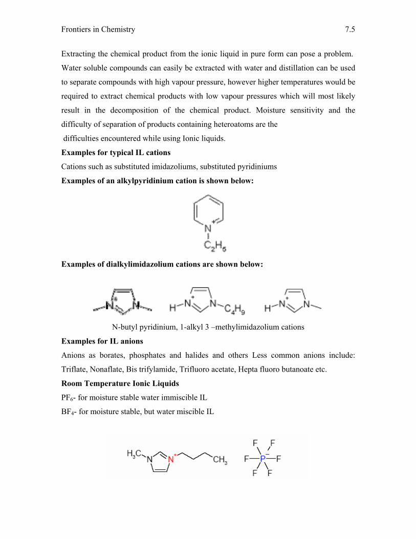
Frontiers in Chemistry
7.5
Extracting the chemical product from the ionic liquid in pure form can pose a problem.
Water soluble compounds can easily be extracted with water and distillation can be used
to separate compounds with high vapour pressure, however higher temperatures would be
required to extract chemical products with low vapour pressures which will most likely
result in the decomposition of the chemical product. Moisture sensitivity and the
difficulty of separation of products containing heteroatoms are the
difficulties encountered while using Ionic liquids.
Examples for typical IL cations
Cations such as substituted imidazoliums, substituted pyridiniums
Examples of an alkylpyridinium cation is shown below:
Examples of dialkylimidazolium cations are shown below:
N-butyl pyridinium, 1-alkyl 3 –methylimidazolium cations
Examples for IL anions
Anions as borates, phosphates and halides and others Less common anions include:
Triflate, Nonaflate, Bis trifylamide, Trifluoro acetate, Hepta fluoro butanoate etc.
Room Temperature Ionic Liquids
PF6- for moisture stable water immiscible IL
BF4- for moisture stable, but water miscible IL
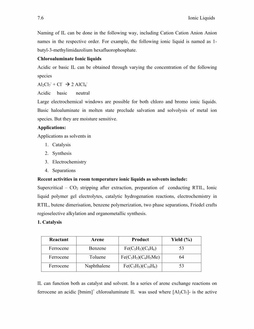
Ionic Liquids
7.6
Naming of IL can be done in the following way, including Cation Cation Anion Anion
names in the respective order. For example, the following ionic liquid is named as 1-
butyl-3-methylimidazolium hexafluorophosphate.
Chloroaluminate Ionic liquids
Acidic or basic IL can be obtained through varying the concentration of the following
species
Al2Cl7- + Cl- 2 AlCl4
-
Acidic basic neutral
Large electrochemical windows are possible for both chloro and bromo ionic liquids.
Basic haloaluminate in molten state preclude salvation and solvolysis of metal ion
species. But they are moisture sensitive.
Applications:
Applications as solvents in
1. Catalysis
2. Synthesis
3. Electrochemistry
4. Separations
Recent activities in room temperature ionic liquids as solvents include:
Supercritical – CO2 stripping after extraction, preparation of conducting RTIL, Ionic
liquid polymer gel electrolytes, catalytic hydrogenation reactions, electrochemistry in
RTIL, butene dimerisation, benzene polymerization, two phase separations, Friedel crafts
regioselective alkylation and organometallic synthesis.
1. Catalysis
Reactant Arene Product Yield (%)
Ferrocene Benzene Fe(C5H5)(C6H6) 53
Ferrocene Toluene Fe(C5H5)(C6H5Me) 64
Ferrocene Naphthalene Fe(C5H5)(C10H8) 53
IL can function both as catalyst and solvent. In a series of arene exchange reactions on
ferrocene an acidic [bmim]+ chloroaluminate IL was used where [Al2Cl7]- is the active
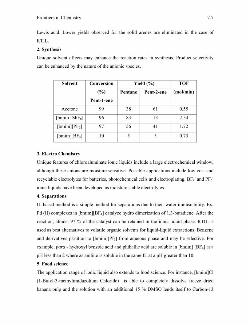
Frontiers in Chemistry
7.7
Lewis acid. Lower yields observed for the solid arenes are eliminated in the case of
RTIL.
2. Synthesis
Unique solvent effects may enhance the reaction rates in synthesis. Product selectivity
can be enhanced by the nature of the anionic species.
Yield (%) Solvent Conversion
(%)
Pent-1-ene
Pentane Pent-2-ene
TOF
(mol/min)
Acetone 99 38 61 0.55
[bmim][SbF6] 96 83 13 2.54
[bmim][PF6] 97 56 41 1.72
[bmim][BF4] 10 5 5 0.73
3. Electro Chemistry
Unique features of chloroaluminate ionic liquids include a large electrochemical window,
although these anions are moisture sensitive. Possible applications include low cost and
recyclable electrolytes for batteries, photochemical cells and electroplating. BF4- and PF6
-
ionic liquids have been developed as moisture stable electrolytes.
4. Separations
IL based method is a simple method for separations due to their water immiscibility. Ex:
Pd (II) complexes in [bmim][BF4] catalyze hydro dimerization of 1,3-butadiene. After the
reaction, almost 97 % of the catalyst can be retained in the ionic liquid phase. RTIL is
used as best alternatives to volatile organic solvents for liquid-liquid extractions. Benzene
and derivatives partition to [bmim][Pf6] from aqueous phase and may be selective. For
example, para - hydroxyl benzoic acid and phthallic acid are soluble in [bmim] [BF4] at a
pH less than 2 where as aniline is soluble in the same IL at a pH greater than 10.
5. Food science
The application range of ionic liquid also extends to food science. For instance, [bmim]Cl
(1-Butyl-3-methylimidazolium Chloride) is able to completely dissolve freeze dried
banana pulp and the solution with an additional 15 % DMSO lends itself to Carbon-13

Ionic Liquids
7.8
NMR analysis. In this way the entire banana compositional makeup of starch, sucrose,
glucose, and fructose can be monitored as a function of banana ripening.
Future aspects of IL research:
As the green chemistry and IL originates at a single point, better utilizations for the social
needs require a joint progress rather than their complimentary development. Insufficient
knowledge in ionic liquids and the ignorance of its implications made this field empty
without using its capabilities. Hence it is necessary to accumulate full information
corresponding to IL for combinatorial development such as comprehensive tocxicity data,
physical properties database, various existing chemistry, comparators for direct
comparison of IL and other traditional solvents, industrial input into a research agenda,
economic synthetic pathways and also a wider availability.
References:
1. P. Walden, Bull. Acad. Sci. 1914, 405
2. H. L. Chum, V. R. Koch, L. L. Miller, R. A. Osteryoung, J. Am. Chem. Soc., 97
(1975) 3264
3. J. S. Wilkes, J. A. Levisky, R. A. Wilson, C. L. Hussey, Inorg. Chem., 21 (1982) 1263
4. R. J. Gale, R. A. Osteryoung, Inorg. Chem., 18 (1979) 1603
5. J. S. Wilkes, M. J. Zaworotko, Chem. Comm. (1992) 965
6. Adam J. Walker and Neil C. Bruce, Chem. Comm., 22 (2004) 2570
7. Martyn J. Earle, José M.S.S. Esperança, Manuela A. Gilea, José N. Canongia Lopes,
Luís P.N. Rebelo, Joseph W. Magee, Kenneth R. Seddon and Jason A. Widegren,
Nature, 439 (2006) 831
8. X. Li, D. Zhao, Z. Fei, L. Wang, Science in China: B 35 (2006) 181
9. Zhao, D.; Fei, Z.; Geldbach, T. J.; Scopelliti, R.; Dyson, P. J., J. Am. Chem. Soc., 126
(2004) 15876
10. C Pretti, C Chiappe, D Pieraccini, M Gregori, F Abramo, G Monni and L Intorre,
Green Chem., 8 (2006) 238
11. Yong Zhou, Current Nanoscience, 1 (2005) 35
12. Xuehui Li, Jinggan Zhao, Qianhe Li, Lefu Wang and Shik Chi Tsang. Dalton Trans,
2007 (Article in press)

Frontiers in Chemistry
7.9
13. Martyn J. Earle and Kenneth R. Seddon, Pure Appl. Chem., 72 (2000) 1391
14. F. Endres, S. Zein El Abedin, Phys. Chem. Chem. Phys., 8 (2006) 2101
15. S. Fujita, H. Kanamaru, H. Senboku and M. Arai., Int. J. Mol. Sci., 7 (2006) 438
16. R. D.Rogers et al. Chem. Comm. (1998) 1765
17. J. Dupont et al. Organometallics, 17 (1998) 815

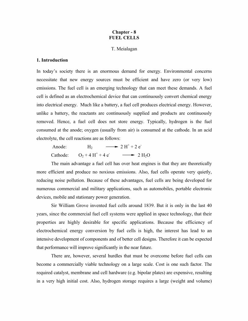
Chapter - 8 FUEL CELLS
T. Meialagan
1. Introduction In today’s society there is an enormous demand for energy. Environmental concerns
necessitate that new energy sources must be efficient and have zero (or very low)
emissions. The fuel cell is an emerging technology that can meet these demands. A fuel
cell is defined as an electrochemical device that can continuously convert chemical energy
into electrical energy. Much like a battery, a fuel cell produces electrical energy. However,
unlike a battery, the reactants are continuously supplied and products are continuously
removed. Hence, a fuel cell does not store energy. Typically, hydrogen is the fuel
consumed at the anode; oxygen (usually from air) is consumed at the cathode. In an acid
electrolyte, the cell reactions are as follows:
Anode: H2 2 H+ + 2 e-
Cathode: O2 + 4 H+ + 4 e- 2 H2O
The main advantage a fuel cell has over heat engines is that they are theoretically
more efficient and produce no noxious emissions. Also, fuel cells operate very quietly,
reducing noise pollution. Because of these advantages, fuel cells are being developed for
numerous commercial and military applications, such as automobiles, portable electronic
devices, mobile and stationary power generation.
Sir William Grove invented fuel cells around 1839. But it is only in the last 40
years, since the commercial fuel cell systems were applied in space technology, that their
properties are highly desirable for specific applications. Because the efficiency of
electrochemical energy conversion by fuel cells is high, the interest has lead to an
intensive development of components and of better cell designs. Therefore it can be expected
that performance will improve significantly in the near future.
There are, however, several hurdles that must be overcome before fuel cells can
become a commercially viable technology on a large scale. Cost is one such factor. The
required catalyst, membrane and cell hardware (e.g. bipolar plates) are expensive, resulting
in a very high initial cost. Also, hydrogen storage requires a large (weight and volume)
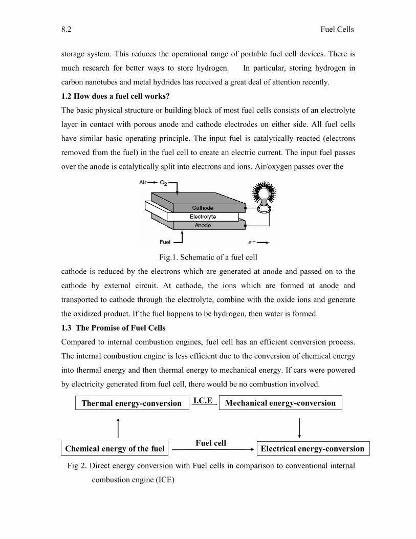
Fuel Cells
8.2
storage system. This reduces the operational range of portable fuel cell devices. There is
much research for better ways to store hydrogen. In particular, storing hydrogen in
carbon nanotubes and metal hydrides has received a great deal of attention recently.
1.2 How does a fuel cell works?
The basic physical structure or building block of most fuel cells consists of an electrolyte
layer in contact with porous anode and cathode electrodes on either side. All fuel cells
have similar basic operating principle. The input fuel is catalytically reacted (electrons
removed from the fuel) in the fuel cell to create an electric current. The input fuel passes
over the anode is catalytically split into electrons and ions. Air/oxygen passes over the
Fig.1. Schematic of a fuel cell
cathode is reduced by the electrons which are generated at anode and passed on to the
cathode by external circuit. At cathode, the ions which are formed at anode and
transported to cathode through the electrolyte, combine with the oxide ions and generate
the oxidized product. If the fuel happens to be hydrogen, then water is formed.
1.3 The Promise of Fuel Cells
Compared to internal combustion engines, fuel cell has an efficient conversion process.
The internal combustion engine is less efficient due to the conversion of chemical energy
into thermal energy and then thermal energy to mechanical energy. If cars were powered
by electricity generated from fuel cell, there would be no combustion involved.
Thermal energy-conversion Mechanical energy-conversion
Fuel cellElectrical energy-conversion
I.C.E
Chemical energy of the fuel Fig 2. Direct energy conversion with Fuel cells in comparison to conventional internal
combustion engine (ICE)
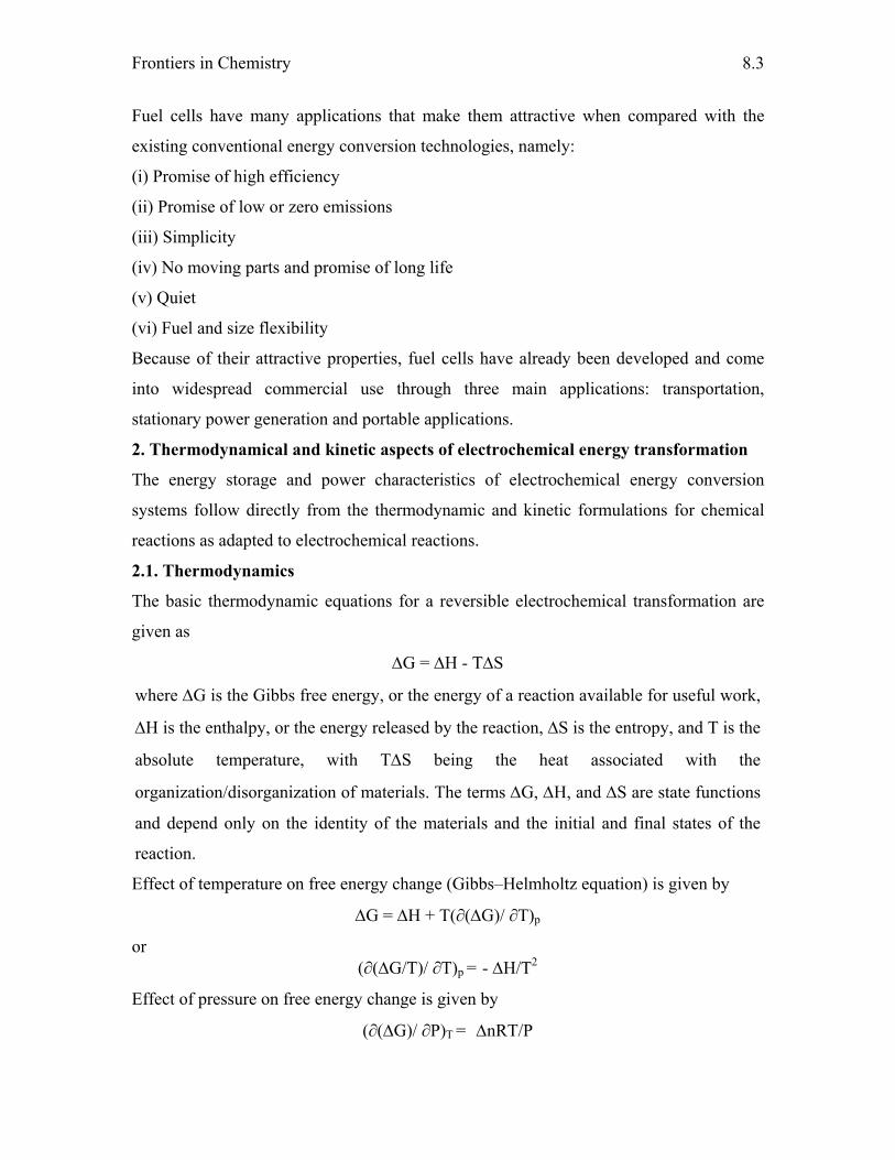
Frontiers in Chemistry
8.3
Fuel cells have many applications that make them attractive when compared with the
existing conventional energy conversion technologies, namely:
(i) Promise of high efficiency
(ii) Promise of low or zero emissions
(iii) Simplicity
(iv) No moving parts and promise of long life
(v) Quiet
(vi) Fuel and size flexibility
Because of their attractive properties, fuel cells have already been developed and come
into widespread commercial use through three main applications: transportation,
stationary power generation and portable applications.
2. Thermodynamical and kinetic aspects of electrochemical energy transformation
The energy storage and power characteristics of electrochemical energy conversion
systems follow directly from the thermodynamic and kinetic formulations for chemical
reactions as adapted to electrochemical reactions.
2.1. Thermodynamics
The basic thermodynamic equations for a reversible electrochemical transformation are
given as
ΔG = ΔH - TΔS
where ΔG is the Gibbs free energy, or the energy of a reaction available for useful work,
ΔH is the enthalpy, or the energy released by the reaction, ΔS is the entropy, and T is the
absolute temperature, with TΔS being the heat associated with the
organization/disorganization of materials. The terms ΔG, ΔH, and ΔS are state functions
and depend only on the identity of the materials and the initial and final states of the
reaction.
Effect of temperature on free energy change (Gibbs–Helmholtz equation) is given by
ΔG = ΔH + T(∂(ΔG)/ ∂T)p
or (∂(ΔG/T)/ ∂T)p = - ΔH/T2
Effect of pressure on free energy change is given by
(∂(ΔG)/ ∂P)T = ΔnRT/P
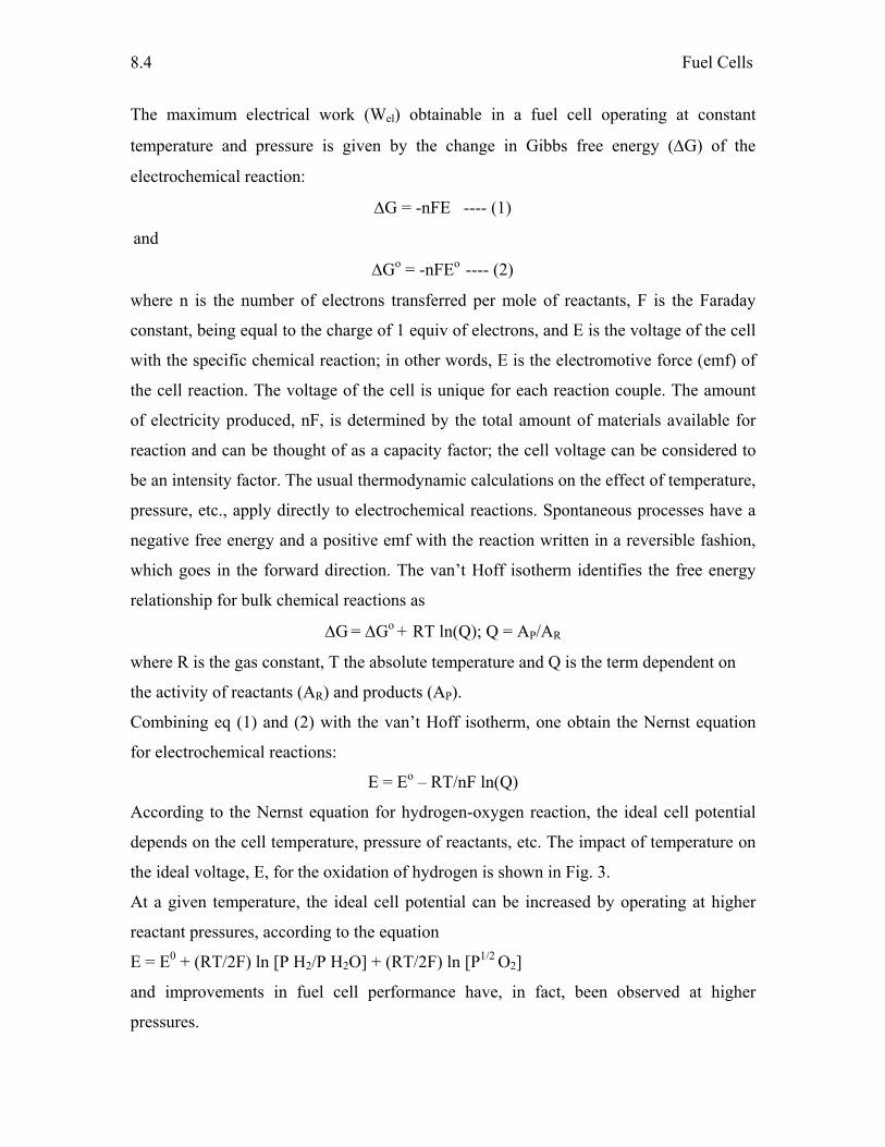
Fuel Cells
8.4
The maximum electrical work (Wel) obtainable in a fuel cell operating at constant
temperature and pressure is given by the change in Gibbs free energy (ΔG) of the
electrochemical reaction:
ΔG = -nFE ---- (1)
and
ΔGo = -nFEo ---- (2)
where n is the number of electrons transferred per mole of reactants, F is the Faraday
constant, being equal to the charge of 1 equiv of electrons, and E is the voltage of the cell
with the specific chemical reaction; in other words, E is the electromotive force (emf) of
the cell reaction. The voltage of the cell is unique for each reaction couple. The amount
of electricity produced, nF, is determined by the total amount of materials available for
reaction and can be thought of as a capacity factor; the cell voltage can be considered to
be an intensity factor. The usual thermodynamic calculations on the effect of temperature,
pressure, etc., apply directly to electrochemical reactions. Spontaneous processes have a
negative free energy and a positive emf with the reaction written in a reversible fashion,
which goes in the forward direction. The van’t Hoff isotherm identifies the free energy
relationship for bulk chemical reactions as
ΔG = ΔGo + RT ln(Q); Q = AP/AR
where R is the gas constant, T the absolute temperature and Q is the term dependent on
the activity of reactants (AR) and products (AP).
Combining eq (1) and (2) with the van’t Hoff isotherm, one obtain the Nernst equation
for electrochemical reactions:
E = Eo – RT/nF ln(Q)
According to the Nernst equation for hydrogen-oxygen reaction, the ideal cell potential
depends on the cell temperature, pressure of reactants, etc. The impact of temperature on
the ideal voltage, E, for the oxidation of hydrogen is shown in Fig. 3.
At a given temperature, the ideal cell potential can be increased by operating at higher
reactant pressures, according to the equation
E = E0 + (RT/2F) ln [P H2/P H2O] + (RT/2F) ln [P1/2 O2]
and improvements in fuel cell performance have, in fact, been observed at higher
pressures.
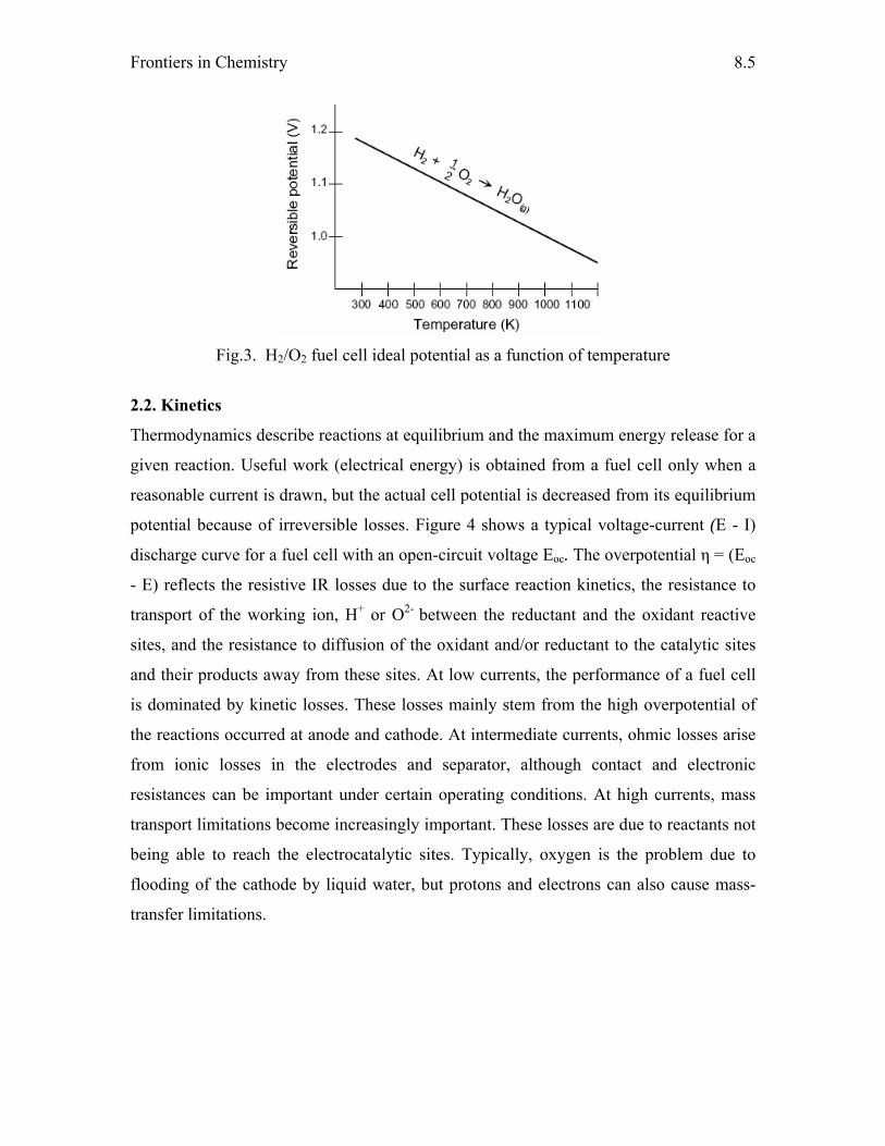
Frontiers in Chemistry
8.5
Fig.3. H2/O2 fuel cell ideal potential as a function of temperature
2.2. Kinetics
Thermodynamics describe reactions at equilibrium and the maximum energy release for a
given reaction. Useful work (electrical energy) is obtained from a fuel cell only when a
reasonable current is drawn, but the actual cell potential is decreased from its equilibrium
potential because of irreversible losses. Figure 4 shows a typical voltage-current (E - I)
discharge curve for a fuel cell with an open-circuit voltage Eoc. The overpotential η = (Eoc
- E) reflects the resistive IR losses due to the surface reaction kinetics, the resistance to
transport of the working ion, H+ or O2- between the reductant and the oxidant reactive
sites, and the resistance to diffusion of the oxidant and/or reductant to the catalytic sites
and their products away from these sites. At low currents, the performance of a fuel cell
is dominated by kinetic losses. These losses mainly stem from the high overpotential of
the reactions occurred at anode and cathode. At intermediate currents, ohmic losses arise
from ionic losses in the electrodes and separator, although contact and electronic
resistances can be important under certain operating conditions. At high currents, mass
transport limitations become increasingly important. These losses are due to reactants not
being able to reach the electrocatalytic sites. Typically, oxygen is the problem due to
flooding of the cathode by liquid water, but protons and electrons can also cause mass-
transfer limitations.
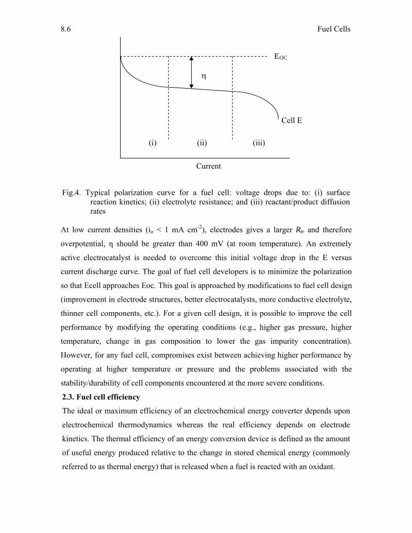
Fuel Cells
8.6
Fig.4. Typical polarization curve for a fuel cell: voltage drops due to: (i) surface reaction kinetics; (ii) electrolyte resistance; and (iii) reactant/product diffusion rates At low current densities (io < 1 mA cm-2), electrodes gives a larger Rtr and therefore
overpotential, η should be greater than 400 mV (at room temperature). An extremely
active electrocatalyst is needed to overcome this initial voltage drop in the E versus
current discharge curve. The goal of fuel cell developers is to minimize the polarization
so that Ecell approaches Eoc. This goal is approached by modifications to fuel cell design
(improvement in electrode structures, better electrocatalysts, more conductive electrolyte,
thinner cell components, etc.). For a given cell design, it is possible to improve the cell
performance by modifying the operating conditions (e.g., higher gas pressure, higher
temperature, change in gas composition to lower the gas impurity concentration).
However, for any fuel cell, compromises exist between achieving higher performance by
operating at higher temperature or pressure and the problems associated with the
stability/durability of cell components encountered at the more severe conditions.
2.3. Fuel cell efficiency
The ideal or maximum efficiency of an electrochemical energy converter depends upon
electrochemical thermodynamics whereas the real efficiency depends on electrode
kinetics. The thermal efficiency of an energy conversion device is defined as the amount
of useful energy produced relative to the change in stored chemical energy (commonly
referred to as thermal energy) that is released when a fuel is reacted with an oxidant.
EOC
(i) (ii) (iii)
Cell E
η
Current
Frontiers in Chemistry
8.7
ε = Useful energy/ΔH
In the ideal case of an electrochemical converter, such as a fuel cell, the change in Gibbs
free energy, ΔG, of the reaction is available as useful electric energy at the temperature of
the conversion. The ideal efficiency of a fuel cell, operating irreversibly, is then
ε = ΔG/ΔH
The most widely used efficiency of a fuel cell is based on the change in the standard free
energy for the cell reaction, for example,
H2 + ½ O2 → H2O (l)
given by
where the product water is in liquid form. At standard conditions of 25 oC (298 K) and 1
atmosphere, the chemical energy (ΔH) in the hydrogen/oxygen reaction is 285.8 kJ/mole,
and the free energy available for useful work is 237.1 kJ/mole. Thus, the thermal
efficiency of an ideal fuel cell operating reversibly on pure hydrogen and oxygen at
standard conditions would be:
εideal = 237.1/285.8 = 0.83
The efficiency of an actual fuel cell can be expressed in terms of the ratio of the operating
cell voltage to the ideal cell voltage. The actual cell voltage is less than the ideal cell
voltage because of the losses associated with cell polarization and the iR loss. The
thermal efficiency of the fuel cell can then be written in terms of the actual cell voltage,
ε = Useful energy/ΔH = Useful power/(ΔG/0.83)
= (Voltsactual x Current)/(Voltsideal x Current/0.83)
= 0.83 (Voltsactual)/(Voltsideal)
As mentioned, the ideal voltage of a cell operating reversibly on pure hydrogen and
oxygen at 1 atm pressure and 25 ºC is 1.229 V. Thus, the thermal efficiency of an actual
fuel cell operating at a voltage of Ecell, based on the higher heating value of hydrogen, is
given by
εideal = 0.83 x Ecell/Eideal = 0.83 x Ecell/1.229 = 0.675 x Ecell
Go = Go - Go - ½ Go H2O H2 O2
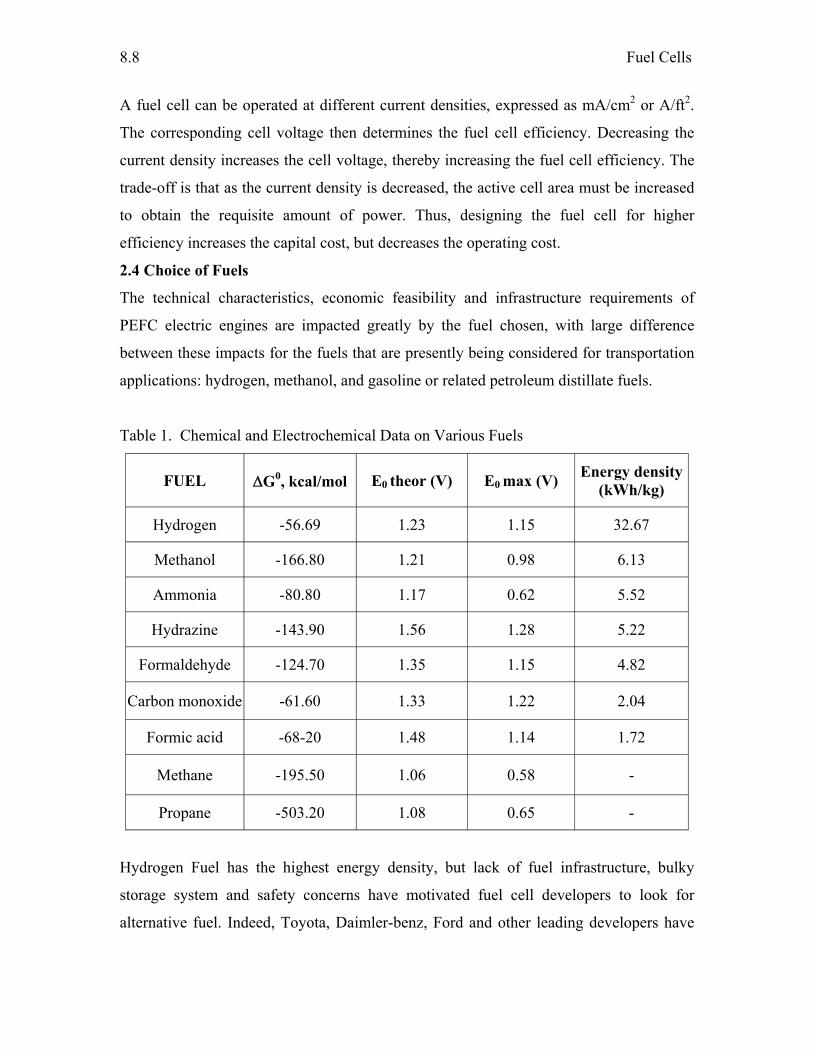
Fuel Cells
8.8
A fuel cell can be operated at different current densities, expressed as mA/cm2 or A/ft2.
The corresponding cell voltage then determines the fuel cell efficiency. Decreasing the
current density increases the cell voltage, thereby increasing the fuel cell efficiency. The
trade-off is that as the current density is decreased, the active cell area must be increased
to obtain the requisite amount of power. Thus, designing the fuel cell for higher
efficiency increases the capital cost, but decreases the operating cost.
2.4 Choice of Fuels
The technical characteristics, economic feasibility and infrastructure requirements of
PEFC electric engines are impacted greatly by the fuel chosen, with large difference
between these impacts for the fuels that are presently being considered for transportation
applications: hydrogen, methanol, and gasoline or related petroleum distillate fuels.
Table 1. Chemical and Electrochemical Data on Various Fuels
FUEL ΔG0, kcal/mol E0 theor (V) E0 max (V) Energy density (kWh/kg)
Hydrogen -56.69 1.23 1.15 32.67
Methanol -166.80 1.21 0.98 6.13
Ammonia -80.80 1.17 0.62 5.52
Hydrazine -143.90 1.56 1.28 5.22
Formaldehyde -124.70 1.35 1.15 4.82
Carbon monoxide -61.60 1.33 1.22 2.04
Formic acid -68-20 1.48 1.14 1.72
Methane -195.50 1.06 0.58 -
Propane -503.20 1.08 0.65 -
Hydrogen Fuel has the highest energy density, but lack of fuel infrastructure, bulky
storage system and safety concerns have motivated fuel cell developers to look for
alternative fuel. Indeed, Toyota, Daimler-benz, Ford and other leading developers have
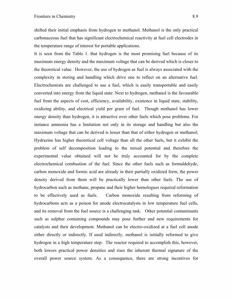
Frontiers in Chemistry
8.9
shifted their initial emphasis from hydrogen to methanol. Methanol is the only practical
carbonaceous fuel that has significant electrochemical reactivity at fuel cell electrodes in
the temperature range of interest for portable applications.
It is seen from the Table 1. that hydrogen is the most promising fuel because of its
maximum energy density and the maximum voltage that can be derived which is closer to
the theoretical value. However, the use of hydrogen as fuel is always associated with the
complexity in storing and handling which drive one to reflect on an alternative fuel.
Electrochemists are challenged to use a fuel, which is easily transportable and easily
converted into energy from the liquid state. Next to hydrogen, methanol is the favourable
fuel from the aspects of cost, efficiency, availability, existence in liquid state, stability,
oxidizing ability, and electrical yield per gram of fuel. Though methanol has lower
energy density than hydrogen, it is attractive over other fuels which pose problems. For
instance ammonia has a limitation not only in its storage and handling but also the
maximum voltage that can be derived is lesser than that of either hydrogen or methanol;
Hydrazine has higher theoretical cell voltage than all the other fuels, but it exhibit the
problem of self decomposition leading to the mixed potential and therefore the
experimental value obtained will not be truly accounted for by the complete
electrochemical combustion of the fuel. Since the other fuels such as formaldehyde,
carbon monoxide and formic acid are already in their partially oxidized form, the power
density derived from them will be practically lower than other fuels. The use of
hydrocarbon such as methane, propane and their higher homologues required reformation
to be effectively used as fuels. Carbon monoxide resulting from reforming of
hydrocarbons acts as a poison for anode electrocatalysts in low temperature fuel cells,
and its removal from the fuel source is a challenging task. Other potential contaminants
such as sulphur containing compounds may pose further and new requirements for
catalysts and their development. Methanol can be electro-oxidized at a fuel cell anode
either directly or indirectly. If used indirectly, methanol is initially reformed to give
hydrogen in a high temperature step. The reactor required to accomplish this, however,
both lowers practical power densities and rises the inherent thermal signature of the
overall power source system. As a consequence, there are strong incentives for
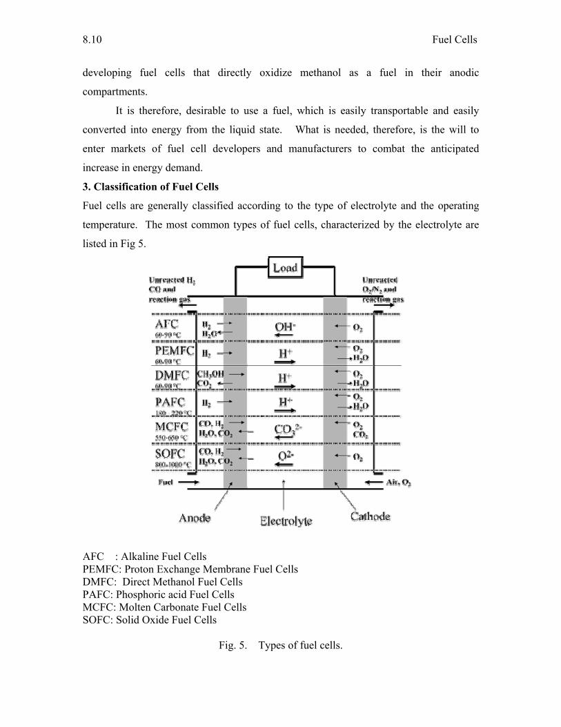
Fuel Cells
8.10
developing fuel cells that directly oxidize methanol as a fuel in their anodic
compartments.
It is therefore, desirable to use a fuel, which is easily transportable and easily
converted into energy from the liquid state. What is needed, therefore, is the will to
enter markets of fuel cell developers and manufacturers to combat the anticipated
increase in energy demand.
3. Classification of Fuel Cells
Fuel cells are generally classified according to the type of electrolyte and the operating
temperature. The most common types of fuel cells, characterized by the electrolyte are
listed in Fig 5.
AFC : Alkaline Fuel Cells PEMFC: Proton Exchange Membrane Fuel Cells DMFC: Direct Methanol Fuel Cells PAFC: Phosphoric acid Fuel Cells MCFC: Molten Carbonate Fuel Cells SOFC: Solid Oxide Fuel Cells
Fig. 5. Types of fuel cells.
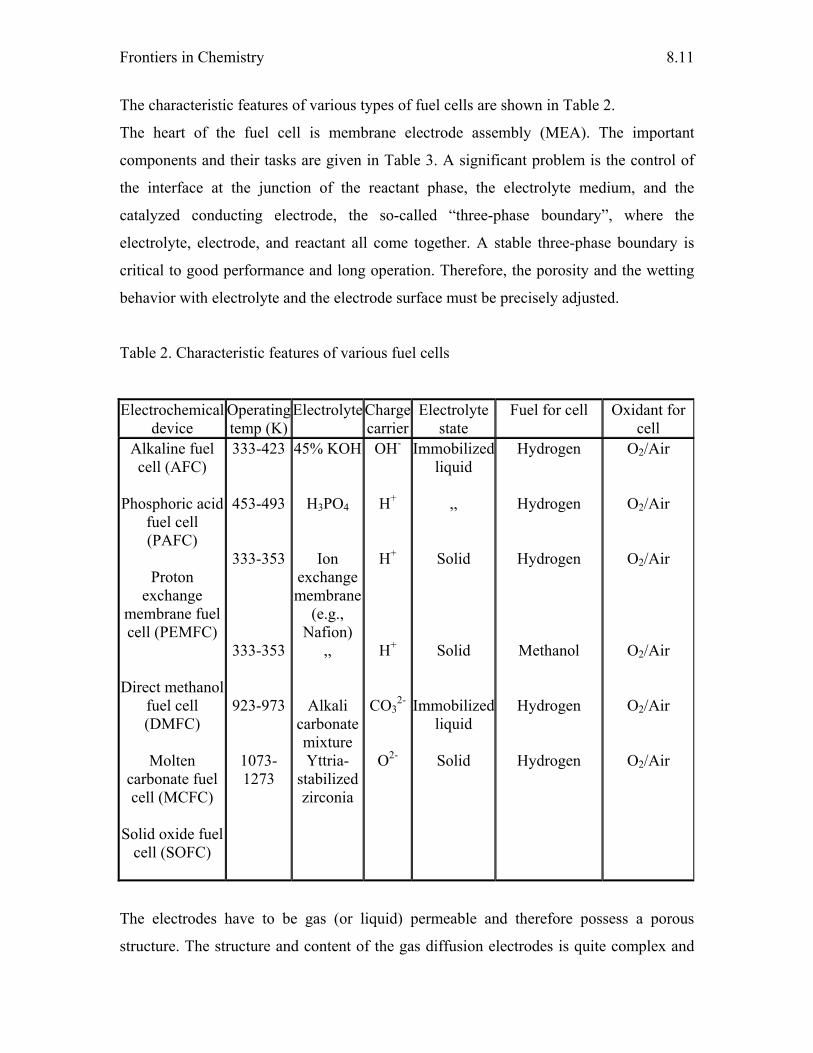
Frontiers in Chemistry
8.11
The characteristic features of various types of fuel cells are shown in Table 2.
The heart of the fuel cell is membrane electrode assembly (MEA). The important
components and their tasks are given in Table 3. A significant problem is the control of
the interface at the junction of the reactant phase, the electrolyte medium, and the
catalyzed conducting electrode, the so-called “three-phase boundary”, where the
electrolyte, electrode, and reactant all come together. A stable three-phase boundary is
critical to good performance and long operation. Therefore, the porosity and the wetting
behavior with electrolyte and the electrode surface must be precisely adjusted.
Table 2. Characteristic features of various fuel cells
Electrochemical device
Operating temp (K)
ElectrolyteCharge carrier
Electrolyte state
Fuel for cell Oxidant for cell
Alkaline fuel cell (AFC)
Phosphoric acid
fuel cell (PAFC)
Proton
exchange membrane fuel cell (PEMFC)
Direct methanol fuel cell (DMFC)
Molten
carbonate fuel cell (MCFC)
Solid oxide fuel
cell (SOFC)
333-423
453-493
333-353
333-353
923-973
1073-1273
45% KOH
H3PO4
Ion exchange membrane
(e.g., Nafion)
,,
Alkali carbonate mixture Yttria-
stabilized zirconia
OH-
H+
H+
H+
CO32-
O2-
Immobilized liquid
,,
Solid
Solid
Immobilized liquid
Solid
Hydrogen
Hydrogen
Hydrogen
Methanol
Hydrogen
Hydrogen
O2/Air
O2/Air
O2/Air
O2/Air
O2/Air
O2/Air
The electrodes have to be gas (or liquid) permeable and therefore possess a porous
structure. The structure and content of the gas diffusion electrodes is quite complex and
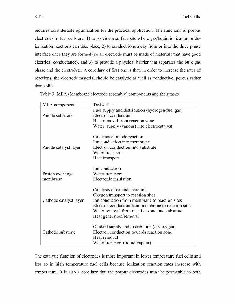
Fuel Cells
8.12
requires considerable optimization for the practical application. The functions of porous
electrodes in fuel cells are: 1) to provide a surface site where gas/liquid ionization or de-
ionization reactions can take place, 2) to conduct ions away from or into the three phase
interface once they are formed (so an electrode must be made of materials that have good
electrical conductance), and 3) to provide a physical barrier that separates the bulk gas
phase and the electrolyte. A corollary of first one is that, in order to increase the rates of
reactions, the electrode material should be catalytic as well as conductive, porous rather
than solid.
Table 3. MEA (Membrane electrode assembly) components and their tasks
MEA component Task/effect Anode substrate Anode catalyst layer Proton exchange membrane Cathode catalyst layer Cathode substrate
Fuel supply and distribution (hydrogen/fuel gas) Electron conduction Heat removal from reaction zone Water supply (vapour) into electrocatalyst Catalysis of anode reaction Ion conduction into membrane Electron conduction into substrate Water transport Heat transport Ion conduction Water transport Electronic insulation Catalysis of cathode reaction Oxygen transport to reaction sites Ion conduction from membrane to reaction sites Electron conduction from membrane to reaction sites Water removal from reactive zone into substrate Heat generation/removal Oxidant supply and distribution (air/oxygen) Electron conduction towards reaction zone Heat removal Water transport (liquid/vapour)
The catalytic function of electrodes is more important in lower temperature fuel cells and
less so in high temperature fuel cells because ionization reaction rates increase with
temperature. It is also a corollary that the porous electrodes must be permeable to both
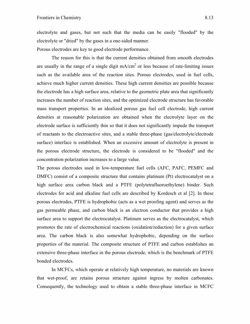
Frontiers in Chemistry
8.13
electrolyte and gases, but not such that the media can be easily "flooded" by the
electrolyte or "dried" by the gases in a one-sided manner.
Porous electrodes are key to good electrode performance.
The reason for this is that the current densities obtained from smooth electrodes
are usually in the range of a single digit mA/cm2 or less because of rate-limiting issues
such as the available area of the reaction sites. Porous electrodes, used in fuel cells,
achieve much higher current densities. These high current densities are possible because
the electrode has a high surface area, relative to the geometric plate area that significantly
increases the number of reaction sites, and the optimized electrode structure has favorable
mass transport properties. In an idealized porous gas fuel cell electrode, high current
densities at reasonable polarization are obtained when the electrolyte layer on the
electrode surface is sufficiently thin so that it does not significantly impede the transport
of reactants to the electroactive sites, and a stable three-phase (gas/electrolyte/electrode
surface) interface is established. When an excessive amount of electrolyte is present in
the porous electrode structure, the electrode is considered to be "flooded" and the
concentration polarization increases to a large value.
The porous electrodes used in low-temperature fuel cells (AFC, PAFC, PEMFC and
DMFC) consist of a composite structure that contains platinum (Pt) electrocatalyst on a
high surface area carbon black and a PTFE (polytetrafluoroethylene) binder. Such
electrodes for acid and alkaline fuel cells are described by Kordesch et al [2]. In these
porous electrodes, PTFE is hydrophobic (acts as a wet proofing agent) and serves as the
gas permeable phase, and carbon black is an electron conductor that provides a high
surface area to support the electrocatalyst. Platinum serves as the electrocatalyst, which
promotes the rate of electrochemical reactions (oxidation/reduction) for a given surface
area. The carbon black is also somewhat hydrophobic, depending on the surface
properties of the material. The composite structure of PTFE and carbon establishes an
extensive three-phase interface in the porous electrode, which is the benchmark of PTFE
bonded electrodes.
In MCFCs, which operate at relatively high temperature, no materials are known
that wet-proof, are retains porous structure against ingress by molten carbonates.
Consequently, the technology used to obtain a stable three-phase interface in MCFC
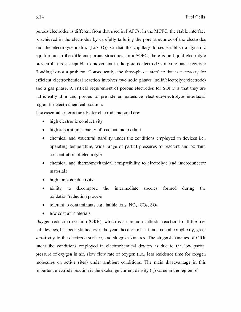
Fuel Cells
8.14
porous electrodes is different from that used in PAFCs. In the MCFC, the stable interface
is achieved in the electrodes by carefully tailoring the pore structures of the electrodes
and the electrolyte matrix (LiA1O2) so that the capillary forces establish a dynamic
equilibrium in the different porous structures. In a SOFC, there is no liquid electrolyte
present that is susceptible to movement in the porous electrode structure, and electrode
flooding is not a problem. Consequently, the three-phase interface that is necessary for
efficient electrochemical reaction involves two solid phases (solid/electrolyte/electrode)
and a gas phase. A critical requirement of porous electrodes for SOFC is that they are
sufficiently thin and porous to provide an extensive electrode/electrolyte interfacial
region for electrochemical reaction.
The essential criteria for a better electrode material are:
• high electronic conductivity
• high adsorption capacity of reactant and oxidant
• chemical and structural stability under the conditions employed in devices i.e.,
operating temperature, wide range of partial pressures of reactant and oxidant,
concentration of electrolyte
• chemical and thermomechanical compatibility to electrolyte and interconnector
materials
• high ionic conductivity
• ability to decompose the intermediate species formed during the
oxidation/reduction process
• tolerant to contaminants e.g., halide ions, NOx, COx, SOx
• low cost of materials
Oxygen reduction reaction (ORR), which is a common cathodic reaction to all the fuel
cell devices, has been studied over the years because of its fundamental complexity, great
sensitivity to the electrode surface, and sluggish kinetics. The sluggish kinetics of ORR
under the conditions employed in electrochemical devices is due to the low partial
pressure of oxygen in air, slow flow rate of oxygen (i.e., less residence time for oxygen
molecules on active sites) under ambient conditions. The main disadvantage in this
important electrode reaction is the exchange current density (jo) value in the region of
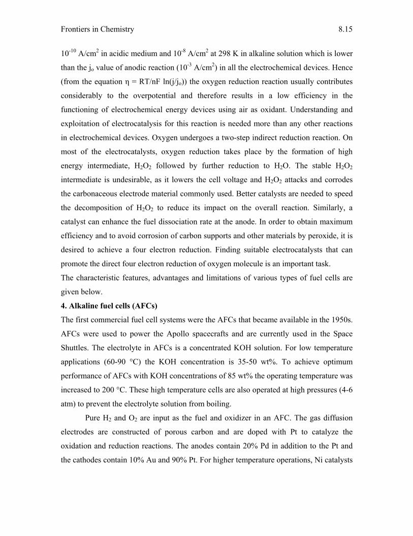
Frontiers in Chemistry
8.15
10-10 A/cm2 in acidic medium and 10-8 A/cm2 at 298 K in alkaline solution which is lower
than the jo value of anodic reaction (10-3 A/cm2) in all the electrochemical devices. Hence
(from the equation η = RT/nF ln(j/jo)) the oxygen reduction reaction usually contributes
considerably to the overpotential and therefore results in a low efficiency in the
functioning of electrochemical energy devices using air as oxidant. Understanding and
exploitation of electrocatalysis for this reaction is needed more than any other reactions
in electrochemical devices. Oxygen undergoes a two-step indirect reduction reaction. On
most of the electrocatalysts, oxygen reduction takes place by the formation of high
energy intermediate, H2O2 followed by further reduction to H2O. The stable H2O2
intermediate is undesirable, as it lowers the cell voltage and H2O2 attacks and corrodes
the carbonaceous electrode material commonly used. Better catalysts are needed to speed
the decomposition of H2O2 to reduce its impact on the overall reaction. Similarly, a
catalyst can enhance the fuel dissociation rate at the anode. In order to obtain maximum
efficiency and to avoid corrosion of carbon supports and other materials by peroxide, it is
desired to achieve a four electron reduction. Finding suitable electrocatalysts that can
promote the direct four electron reduction of oxygen molecule is an important task.
The characteristic features, advantages and limitations of various types of fuel cells are
given below.
4. Alkaline fuel cells (AFCs)
The first commercial fuel cell systems were the AFCs that became available in the 1950s.
AFCs were used to power the Apollo spacecrafts and are currently used in the Space
Shuttles. The electrolyte in AFCs is a concentrated KOH solution. For low temperature
applications (60-90 °C) the KOH concentration is 35-50 wt%. To achieve optimum
performance of AFCs with KOH concentrations of 85 wt% the operating temperature was
increased to 200 °C. These high temperature cells are also operated at high pressures (4-6
atm) to prevent the electrolyte solution from boiling.
Pure H2 and O2 are input as the fuel and oxidizer in an AFC. The gas diffusion
electrodes are constructed of porous carbon and are doped with Pt to catalyze the
oxidation and reduction reactions. The anodes contain 20% Pd in addition to the Pt and
the cathodes contain 10% Au and 90% Pt. For higher temperature operations, Ni catalysts
Fuel Cells
8.16
are also used. Ni is used for the inter connectors in an AFC stack. The AFC operates at up
to ∼1 A/cm2 at 0.7 V.
The mobile ions in the system are the OH- ions in the alkaline solution that are
transported from the cathode, where reduction of O2 occurs, to the anode, where
oxidation of H2 occurs. Water is produced at the anode. The following reactions define
the operation of AFCs:
At anode: H2 + 2 OH-→ 2 H2O + 2 e-
At cathode: ½ O2 + H2O + 2 e- → 2 OH-
Cell reaction: H2 + ½ O2 → H2O
Although AFCs have the highest electrical efficiency of all fuel cell systems (60%
LHV), they are extremely sensitive to impurities. The presence of N2 and impurities in
the gas streams substantially reduce the cell efficiency. The presence of even small
amounts of CO2 is detrimental to the long-term performance of AFCs because K2CO3
forms and inhibits gas diffusion through the carbon electrodes. The small amounts of CO2
in air (~300 ppm) preclude the use of air as the oxidant in an AFC. This restriction limits
the use of these fuel cell systems to applications such as space and military programs,
where the high cost of providing pure H2 and O2 is permissible. Because pure gases are
used, AFCs can generate pure, potable water for consumption during space missions.
5. Phosphoric acid fuel cells (PAFCs)
Other than the AFCs, PAFCs are closer to commercialization than other fuel cell systems.
The two intended commercial uses for PAFCs are 1) distributed power using reformed
natural gas as a fuel; and 2) for small-scale, on-site cogeneration. Air is used as the
oxidant. In contrast to the AFC, PAFCs are tolerant of CO2 because concentrated
phosphoric acid (H3PO4) is used as the electrolyte. Compared to other inorganic acids,
phosphoric acid has relatively low volatility at operating temperatures of 150-220 °C.
Protons migrate from the anode to the cathode through 100% H3PO4 that is immobilized
in a SiC-poly(tetrafluoroethylene) matrix. Electrodes are made of platinized, gas
permeable graphite paper. The water produced at the cathode is removed with the excess
O2 and the N2. PAFCs have demonstrated excellent thermal, chemical, and
electrochemical stability compared to other fuel cell systems. PAFCs are defined by the
following reactions:
Frontiers in Chemistry
8.17
At anode: H2 → 2 H+ + 2 e-
At cathode: ½ O2 + 2 H+ + 2 e- → H2O
Cell reaction: H2 + ½ O2 → H2O
To optimize the ionic conductivity of the electrolyte, operating temperatures are
maintained between 150-220 °C at pressures ranging from atmospheric to ~8 atm.
Reduction of oxygen is slower in an acid electrolyte than in an alkaline electrolyte, hence
the need for Pt metal in the electrodes to help catalyze the reduction reactions. CO
poisoning of the Pt electrodes is slower at PAFC operating temperatures than at lower
temperatures so up to 1% CO in the fuel gas produced during the reforming process can
be tolerated. At lower temperatures CO poisoning of the Pt in the anode is more severe.
Currently, Pt based materials were used as anode and cathode. The anode operates at
nearly reversible voltage with ∼0.1 mg/cm2 catalyst loading. The cathode requires a
higher catalyst loading of ∼1 mg/cm2 of catalyst. PAFCs are already semicommercially
available in container packages (200 kW) for stationary electricity generation. Hundreds
of units have been installed all over the world.
Aside from the CO produced during hydrocarbon reforming, the concentration of
other impurities must be low compared to the reactants and diluents. Sulfur gases (mainly
H2S and COS) that originate from the fuel gas can poison the anode by blocking active
sites for H2 oxidation on the Pt surface. Molecular nitrogen acts as a diluent but nitrogen
compounds like NH3, HCN, and NOx are potentially harmful impurities. NH3 acts as a
fuel, however, the oxidant nitrogen compounds can react with the H3PO4 to form a
phosphate salt, (NH4)H2PO4. Unacceptable performance losses can occur if the
concentration of this phosphate salt in the electrolyte increases above 0.2 mole%.
6. Proton exchange membrane fuel cells (PEMFCs)
PEM fuel cells are a serious candidate for automotive applications, but also for small-
scale distributed power generation, and for portable power applications as well. PEMFCs
contain a proton conducting ion exchange membrane as the electrolyte material. The
membrane material is a fluorinated sulfonic acid polymer commonly referred to by the
trade name given to a material developed and marketed by DuPont - Nafion®. The acid
molecules are immobile in the polymer matrix; however, the protons associated with
these acid groups are free to migrate through the membrane from the anode to the
Fuel Cells
8.18
cathode, where water is produced. The electrodes in a PEMFC are made of porous carbon
cloths doped with a mixture of Pt and Nafion®. The catalyst content of the anode is ∼0.1
mg/cm2, and that of the cathode is ∼0.5 mg/cm2. The PEMFC operates at ∼1 A/cm2 at 0.7
V.
PEMFCs use H2 as the fuel and O2 as the oxidant. The PEMFC is insensitive to
CO2 so air can be used instead of pure O2 and reforming hydrocarbon fuels can produce
the H2. Thermally integrating fuel reformers with operating temperatures of 700-800 °C
with PEMFCs that operate at 80 °C is a considerable challenge. The PEMFC is defined
by the following reactions:
At anode: H2 → 2 H+ + 2 e-
At cathode: ½ O2 + 2 H+ + 2 e- → H2O
Cell reaction: H2 + ½ O2 → H2O
PEMFCs have received considerable attention lately as the primary power source
in electric vehicles for several reasons. Since the electrolyte is a polymeric material, there
is no free corrosive liquid inside the cell (water is the only liquid), hence material
corrosion is kept to a minimum. PEMFCs are also simple to fabricate and have a
demonstrated long life. On the other hand, the polymer electrolyte (Nafion®) is quite
expensive and Pt loadings in the electrodes are quite high so the fuel cell cost is high. The
power and efficiency of a PEMFC is also dependent on the water content of the polymer
electrolyte, so water management in the membrane is critical for efficient operation. The
conductivity of the membrane is a function of the number of water molecules available
per acid site and if the membrane dries out, fuel cell power and efficiency decrease. If
water is not removed from the PEMFC the cathode can become flooded which also
degrades cell performance. For high temperature PEMFCs, polybenimidazole based
membranes will be preferred.
The required moisture content of the membrane is what limits the operating
temperature of a PEMFC to less than 120 °C. This temperature ensures that the by-
product water does not evaporate faster than it is produced. Low operating temperatures
equates to high Pt loadings in the electrodes to efficiently catalyze the oxidation and
reduction reactions. The Pt content of the electrodes also necessitates that the CO content
of the fuel gas be very low (< 5 ppm) because CO blocks the active sites in the Pt
Frontiers in Chemistry
8.19
catalyst. Therefore, if a hydrocarbon reformer is used to produce H2, the CO content of
the fuel gas needs to be greatly reduced. This is usually accomplished by oxidation of CO
to CO2, using a water gas shift reactor, or using pressure swing adsorption to purify the
hydrogen.
7. Direct methanol fuel cells (DMFCs)
The DMFC uses the same basic cell construction as for the PEMFC. It has the advantage
of a liquid fuel in that is easy to store and transport. There is no need for the reformer to
convert the hydrocarbon fuel into hydrogen gas. Methanol is the liquid fuel having high
energy density (6.2 kWh/kg) among all the liquid fuels and next to hydrogen. The anode
feedstock is a methanol and water mixture or neat methanol, depending on cell
configuration. The DMFC is under development as a power source for portable electronic
devices such as notebook computers and cellular phones. The pure methanol or a
methanol-water mixture would be stored in a cartridge similar to that used for fountain
pens. Refueling would involve the quick replacement of the cartridge. The reaction for
the direct conversion of methanol has a similar voltage as for hydrogen.
DMFCs use CH3OH as the fuel and O2 as the oxidant. Due to the chemical
similarity of water and methanol, the methanol has considerable solubility in the polymer
membrane, leading to significant crossover from the anode side to the cathode side of the
cell. On reaching the cathode, the methanol is oxidized. This significantly lowers the
cathode voltage and the overall efficiency of cell operation. The typical DMFC yields
∼0.5 V at 400 mA/cm2 at 60 °C. The DMFC is defined by the following reactions:
At anode: CH3OH + H2O → CO2 + 6 H+ + 6 e-
At cathode: 3/2 O2 + 6 H+ + 6 e- → 3 H2O
Cell reaction: CH3OH + 3/2 O2 → CO2 + 2 H2O
The main disadvantage of the DMFC system is the relative low power density,
which has to be significantly improved if the DMFC should be a viable alternative to the
PEMFC plus reformer system. The lower cell performance of a DMFC is caused by the
poor kinetics of the anode reaction. The oxidation reaction proceeds through the
formation of carbon monoxide as an intermediate which strongly adsorbs on the surface
of a Pt catalyst. Therefore, a potential, which is more anodic than the thermodynamic
value, is needed to obtain a reasonable reaction rate. In contrast to the PEMFC, where it
Fuel Cells
8.20
is mainly the cathode that is kinetically hindered, both electrodes of a DMFC suffer from
kinetic losses. Consequently, numerous materials were studied to find an electrode
material that displays an enhanced catalytic activity and therefore lower overpotentials
towards the methanol oxidation. At present, the most active anode catalysts are based on
Pt–Ru alloys. Ruthenium reduces the poisoning effect by lowering the overpotentials at
the anode and thus increases considerably the catalytic activity of pure platinum. The
platinum-ruthenium catalyst loadings for the anode are higher than for the PEMFC and
are in the range of 1-3 mg/cm2. Cathode catalysts are based on Pt and Pt alloys (Pt-M
where M = Cr, Co, Fe and Ni).
8. Molten carbonate fuel cells (MCFCs)
MCFCs contain an electrolyte that is a combination of alkali (Li, Na, and K) carbonates
stabilized in a LiAlO2 ceramic matrix. The electrolyte should be pure and relatively free
of alkaline earth metals. Contamination by more than 5-10 mole % of CaCO3, SrCO3, and
BaCO3 can lead to performance loss. Electrons are conducted from the anode through an
external circuit to the cathode and negative charge is conducted from the cathode through
the electrolyte by CO3 2- ions to the anode. Water is produced at the anode and removed
with CO2. The CO2 needs to be recycled back to the fuel cell to maintain the electrolyte
composition. This adds complexity to the MCFC systems. The oxidation and reduction
reactions that define MCFC operation are as follows:
At anode: H2 + CO32--→ H2O + CO2 + 2 e-
CO + CO32--→ CO2 + 2 e-
Shift: CO + H2O → H2 + CO2
At cathode: ½ O2 + CO2 + 2 e- → CO32-
Cell reaction: H2 + ½ O2 → H2O
MCFCs typically operate at temperatures between 600-700 °C providing the
opportunity for high overall system operating efficiencies, especially if the waste heat
from the process can be utilized in the fuel reforming step or for cogeneration. Operating
temperatures higher than 700 °C lead to diminishing gains in fuel cell performance
because of electrolyte loss from evaporation and increased high temperature materials
corrosion. Typical operating parameters are ∼150 mA/cm2 at 0.8 V at 600 °C.
Frontiers in Chemistry
8.21
The high operating temperature of a MCFC system also provides for greater fuel
flexibility; a variety of hydrocarbon fuels (natural gas, alcohols, landfill gas, syn gas from
petroleum coke, coal and biomass, etc.) can be reformed to generate hydrogen for the fuel
cell. The CO from biomass and coal gasification product gas and reformed hydrocarbons
is not used directly as a fuel but when mixed with water vapor can produce additional
hydrogen via the water-gas shift reaction. Oxygen or air is used as the oxidant. An
attractive design incorporates an internal fuel reformer within the fuel cell eliminating the
need for a separate fuel processor.
A higher operating temperature also means that less expensive materials can be used for
the electrocatalysts in the electrodes; Pt is not required and Ni is used as the catalyst. The
Ni in the cathode becomes oxidized and lithiated (from contact with the electrolyte)
during initial operation of a MCFC so that the active material is Li-doped NiO.
Unfortunately, NiO is soluble in molten carbonates leading to the possible dissolution of
the cathode and dispersion of metallic nickel in the electrolyte, which can eventually
short-circuit the electrodes. This is one of the materials issues that is being investigated to
improve the long-term operability of MCFC systems. Recently, LiCoO2 and Li2MnO3
were found to be alternative materials as cathode.
The anode contains Ni doped with 10% Cr to promote sintering. An external
methane reformer is not needed in a MCFC system because the presence of Ni in the
anode at MCFC operating temperatures is very effective for internal CH4 reforming at the
anode. Internal methane reforming can increase overall system efficiencies, but can also
induce unwanted temperature gradients inside the fuel cell that may cause materials
problems. Catalyst poisoning is also an issue if the sulfur content of the reagent gases is
greater than 10 ppm, similar to all Ni-based fuel-reforming systems. Coke formation on
the anode from fuel reforming can also be an issue.
9. Solid oxide fuel cells (SOFCs)
SOFC systems operate between 900-1000 °C, higher than any other fuel cell system. At
these operating temperatures, fuel composition is not an issue because in the presence of
enough water vapor and oxygen complete oxidation will be achieved, even in the absence
of catalytic materials. High overall system efficiencies are possible with waste heat
recovery. The electrolyte material in a SOFC is yttrium (8-10 mol%) stabilized zirconia
Fuel Cells
8.22
(YSZ). This material is a solid with a stable cubic structure and very high oxide
conductivity at SOFC operating temperatures. The mobile O2- ions migrate from the
cathode to the anode where water is produced. The electrochemical reactions occurring in
a SOFC system are as follows:
At anode: H2 + O2- → H2O + 2 e-
At cathode: ½ O2 + 2e-→ O2-
Cell reaction: H2 + ½ O2 → H2O
Similar to the MCFC systems, the high operating temperatures of the SOFCs provides
fuel flexibility without the need for expensive catalysts in the electrodes. The cathode in a
SOFC consists of mixed oxides with a perovskite crystalline structure, typically Sr-doped
lanthanum manganate (LaMnO3). The anode material is a Ni cermet (ceramic and metal
composite). It contains metallic Ni for catalytic activity in an YSZ support. The YSZ
adds mechanical, thermal, and chemical stability, chemical and thermal compatibility
between the anode and the electrolyte is not an issue. Like the MCFC systems, internal
methane steam reforming at the Ni-based anode in the presence of water vapor is possible
in SOFC systems. The cells operate at ∼1 A/cm2 at 0.7 V.
Overall, SOFC systems can tolerate impurities because of their high operating
temperatures. Sulfur tolerances can be up to two orders of magnitude higher in SOFCs
than in other fuel cell systems because of the high operating temperatures. Energy
efficient, high temperature sulfur removal methods are used to lower the sulfur content of
the gas to less than 10 ppm. At the same time, the high operating temperatures of SOFCs
can cause considerable materials issues like material incompatibilities (thermal and
chemical) and corrosion.
Significant research and development efforts have gone into technically and cost-
effectively addressing materials issues in SOFC systems for commercial applications.
This is reflected in the variety of designs for SOFC systems. There are three general types
of designs for SOFC systems: tubular, bipolar monolithic, and bipolar planar. The bipolar
designs have a bipolar plate that prevents reactant gases in adjacent cells from mixing and
provides serial electrical interconnectivity between cells. The single cells are stacked with
interconnectors, gas channels, and sealing elements in between. There are two types of
tubular designs: seal-less and segmented cell in-series. A single cell in a tubular SOFC
Frontiers in Chemistry
8.23
consists of a long porous YSZ ceramic tube that acts as a substrate. The cathode,
followed by the electrolyte, and finally the anode are deposited on the outer surface of the
tube. A portion of the tube is left with a strip of the cathode covered by the interconnector
material to make the electrical connection. Individual tubes are arranged in a case and air
flows inside the tubes while fuel flows around the outside of the tubes.
Developments in SOFC systems that operate at intermediate temperatures (550-
800 °C) are currently receiving considerable attention. Reducing the operating
temperature of SOFC systems is being pursued in an attempt to reduce the cost of these
systems. Some of the benefits of a reduced operating temperature include: better thermal
integration with fuel reformers and sulfur removal systems, reduced material issues such
as less thermal stress and more material flexibility, lower heat loss, shorter time to
achieve operating temperature, and less corrosion. Capitalizing on the benefits of lower
SOFC operating temperatures is an area of continued and future research and
development.
References
1. W. Vielstitch, Fuel Cells, Wiley/Interscience, London, 1965.
2. K. Kordesch and G. Simader, Fuel cells and their applications, VCH, Weinheim,
Germany 1996.
3. L. Carrette, K. A. Friedrich and U. Stimming, FUEL CELLS 1 (2001) 1.
4. Martin Winter and Ralph J. Brodd, Chem. Rev. 104 (2004) 4245.
5. F. Hine, Electrode Process and Electrochemical Engineering, Vol. 306, Plenum Press,
New York, 1985.
6. Wolf Vielstich, Hubert A. Gasteiger and Anold Lamm. (Eds), “Hand book of
Fuel Cells – Fundamentals, Technology and applications, Vol. 2: Electrocatalysis”,
John Wiley & Sons, 2003.
7. B. Viswanathan and M. Aulice scibioh, Fuel Cells, Principles and Applications,
Universities Press (India) Limited, 2006.

Chapter - 9 NUCLEAR ENERGY OPTIONS
The sun shall be turned into darkness, and the moon into blood, before that great and notable day of the Lord come:
The Holy Bible (The Acts 2:20) While the sun, or the light, or the moon, or the stars, be not darkened, nor the clouds return after the rain:
The Holy Bible (Ecclesiastes 12:2)
Introduction: Clearly, energy security and energy independence are the two challenges ahead of any
nation in this new millennium. The global appetite for energy is simply too great and
recurring as well. There is an abrupt need to look something beyond incremental because
the additional energy needed is greater than the total of all the energy currently produced.
Energy sources are inevitable for progress and prosperity [1].
Energy is inevitable for the very sustenance of human life. There is an abrupt need for
vast, unperishable, inexhaustible, long lasting and human friendly energy sources in view
of the fast depleting fossil fuel based non renewable energy resources. In this regard can
we think of Nuclear energy as a better option? Why? Why not? [2]
The two challenges for human society in the 21st century are the purposeful transition
towards a sustainable energy future and also to ensure effective conservation of natural
resources across the globe [3].
It has now become imperative to consider what the chances are for saving humanity from
energy poverty through controlled power from the nucleus of the atom.
The issue of “Nuclear Energy Options” was and is a matter of unending debate with
views diverging and opinions contradicting. This can be exemplified from the following
two well known quotes:
“Lord, we are especially thankful for nuclear power, the cleanest, safest energy source
there is. Except for solar, which is just a pipe dream.” – Homer Simpson
“The nuclear power option - expensive, ineffective, unnecessary and problem-
multiplying.” – Professor Stuart White
Nuclear Energy Options
9.2
It is generally argued that improving energy efficiency of conventional energy generation
process and exploitation of renewable energy sources like wind energy and solar energy
can be cheap option for green house gas reduction compared to nuclear energy. Further
it appears that nuclear waste management (disposal), decommissioning and proliferation
risks involved in Nuclear energy option multiply the existing problem.
The choice of Nuclear Energy hold great promise of inexhaustible energy for
manifold applications that can quench human thirst satisfy the need if exploited with
wisdom. But the same can be extremely disastrous leading to the destruction of life on
earth if used ignorantly.
The July 2005 Indo-US Nuclear deal:
The issue of Nuclear energy gained vitality with the recent remarkable July 2005 Indo-
US Nuclear agreement deal according to which the US government should adjust U.S.
laws and policies to enable full civil nuclear energy cooperation and trade with India.
But all is not good with the deal and the existing obstacles are clear, namely, lifetime fuel
guarantees for Indian civilian reactors in return for perpetuity safeguards, the U.S.
insistence on "fallback" bilateral safeguards in addition to IAEA (International Atomic
Energy Agency) safeguards, the U.S. refusal to allow India to import components and
technology for safeguarded reprocessing and enrichment activity, the U.S. refusal to
allow reprocessing of spent fuel, India's IAEA safeguards agreement and the timing and
nature of the Nuclear Suppliers Group's decision to amend its guidelines to allow
commerce with India.
Irrespective of the afore mentioned hindrances it should be noted that India’s
advancement in the exploitation of Nuclear energy is not dependent on the mercy of any
foreign nation for we have already achieved self-reliance in this field and cooperation
from external sources will only be an addition to our efforts in this direction harnessing
nuclear energy. Break down of cooperation from other nations is no loss.
The first stage of India's nuclear power programme, presently consisting of 12
Pressurised Heavy Water Reactors (PHWRs), is completely in the industrial domain. As
result of the consolidation of the entire work done in the last 50 years, we now have a
clearly defined roadmap for future R&D and its commercialization. we have now
succeeded in this very frontline technology in all its dimensions. We have different
Frontiers in Chemistry
9.3
technologies for various applications, namely, Nuclear energy applications in agriculture,
health, food security and so on. In addition we have contributed towards nuclear weapons
ability in the country. India today is a country with nuclear weapons to ensure its long-
term security. At the same time, we have domestic capability to guarantee long-term
energy security in a manner that will help in preserving the environment and avoiding the
adverse impact of climate change.
Thorium utilization – Indian context:
In Indian context owing to the availability of rich reserves of Thoria development and
construction of breeder reactors is of paramount importance and it forms one of the key
elements in solving our future energy needs.
Fortunately, India is blessed with natural wealth. Monazite has been used as the source of
thorium up to the present time . The deposits are often coloured black by the presence of
Magnetoite, or red by the presence of garnet. Monazite is characterized by its chemical
stability. Solvent extraction process suits well for thorium separation and tributyl
phosphate is a particularly promising solent. This extracts thorium and leavesth rare
earths in the aqueous phase. India's vast thorium reserves amount to nearly one-third of
world's thorium reserves. Effective utilization of the available vast thorium reserves for
harnessing Nuclear energy for the benefit of mankind should be one of the worthy targets
of the India's Nuclear Programme. Monazite is the potential source of Uranium. The
Monazite has been eroded from igneous rocks and transported by streams to form alluvial
deposits. The beach sand of the Indian Malabar and Coromandel coasts are very rich in
Monazite and are estimated to contain upto 1,80,000 tons of Thorium in an easily
extractable form. An important Thorium reserve further inland has been discovered also,
in the state of Bihar; this is estsimated to contain over 3,00,000 tons of thorium at a
concentration of over 10 percent. India has to fall back to its thorium reserves for energy
security on a sustainable basis. Road map should be prepared for introducing Thorium (as
ThO2) in place of UO2 in the blanket zone of FBR's (fast breeders reactors) at an
appropriate growth level of installed nuclear power capacity in the second stage. One of
the major tasks in hand is to start construction of the thorium fuel based 300 MWe
Advanced Heavy water reactor (AHWR). Other large scale deposits of Monazite occur in
Brazil, Taiwan, Ceylon and the USA.
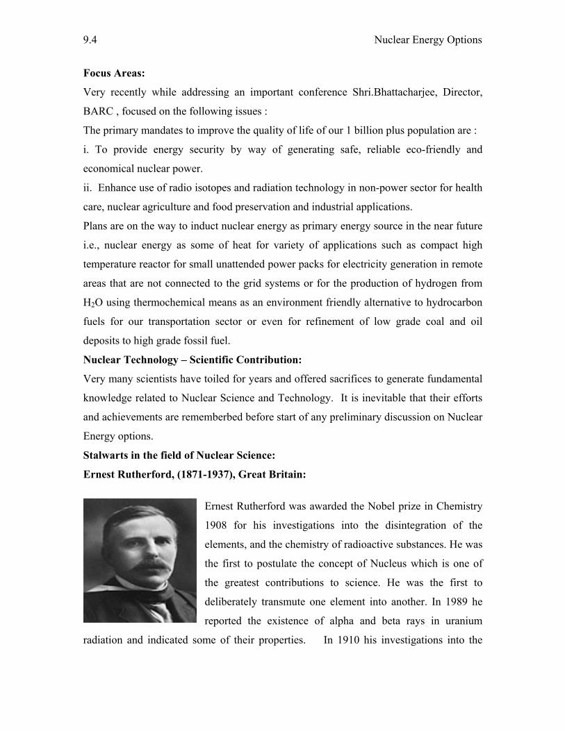
Nuclear Energy Options
9.4
Focus Areas:
Very recently while addressing an important conference Shri.Bhattacharjee, Director,
BARC , focused on the following issues :
The primary mandates to improve the quality of life of our 1 billion plus population are :
i. To provide energy security by way of generating safe, reliable eco-friendly and
economical nuclear power.
ii. Enhance use of radio isotopes and radiation technology in non-power sector for health
care, nuclear agriculture and food preservation and industrial applications.
Plans are on the way to induct nuclear energy as primary energy source in the near future
i.e., nuclear energy as some of heat for variety of applications such as compact high
temperature reactor for small unattended power packs for electricity generation in remote
areas that are not connected to the grid systems or for the production of hydrogen from
H2O using thermochemical means as an environment friendly alternative to hydrocarbon
fuels for our transportation sector or even for refinement of low grade coal and oil
deposits to high grade fossil fuel.
Nuclear Technology – Scientific Contribution:
Very many scientists have toiled for years and offered sacrifices to generate fundamental
knowledge related to Nuclear Science and Technology. It is inevitable that their efforts
and achievements are rememberbed before start of any preliminary discussion on Nuclear
Energy options.
Stalwarts in the field of Nuclear Science:
Ernest Rutherford, (1871-1937), Great Britain:
Ernest Rutherford was awarded the Nobel prize in Chemistry
1908 for his investigations into the disintegration of the
elements, and the chemistry of radioactive substances. He was
the first to postulate the concept of Nucleus which is one of
the greatest contributions to science. He was the first to
deliberately transmute one element into another. In 1989 he
reported the existence of alpha and beta rays in uranium
radiation and indicated some of their properties. In 1910 his investigations into the
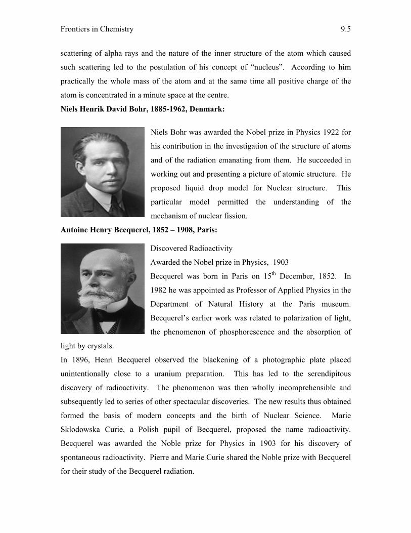
Frontiers in Chemistry
9.5
scattering of alpha rays and the nature of the inner structure of the atom which caused
such scattering led to the postulation of his concept of “nucleus”. According to him
practically the whole mass of the atom and at the same time all positive charge of the
atom is concentrated in a minute space at the centre.
Niels Henrik David Bohr, 1885-1962, Denmark:
Niels Bohr was awarded the Nobel prize in Physics 1922 for
his contribution in the investigation of the structure of atoms
and of the radiation emanating from them. He succeeded in
working out and presenting a picture of atomic structure. He
proposed liquid drop model for Nuclear structure. This
particular model permitted the understanding of the
mechanism of nuclear fission.
Antoine Henry Becquerel, 1852 – 1908, Paris: Discovered Radioactivity
Awarded the Nobel prize in Physics, 1903
Becquerel was born in Paris on 15th December, 1852. In
1982 he was appointed as Professor of Applied Physics in the
Department of Natural History at the Paris museum.
Becquerel’s earlier work was related to polarization of light,
the phenomenon of phosphorescence and the absorption of
light by crystals.
In 1896, Henri Becquerel observed the blackening of a photographic plate placed
unintentionally close to a uranium preparation. This has led to the serendipitous
discovery of radioactivity. The phenomenon was then wholly incomprehensible and
subsequently led to series of other spectacular discoveries. The new results thus obtained
formed the basis of modern concepts and the birth of Nuclear Science. Marie
Sklodowska Curie, a Polish pupil of Becquerel, proposed the name radioactivity.
Becquerel was awarded the Noble prize for Physics in 1903 for his discovery of
spontaneous radioactivity. Pierre and Marie Curie shared the Noble prize with Becquerel
for their study of the Becquerel radiation.
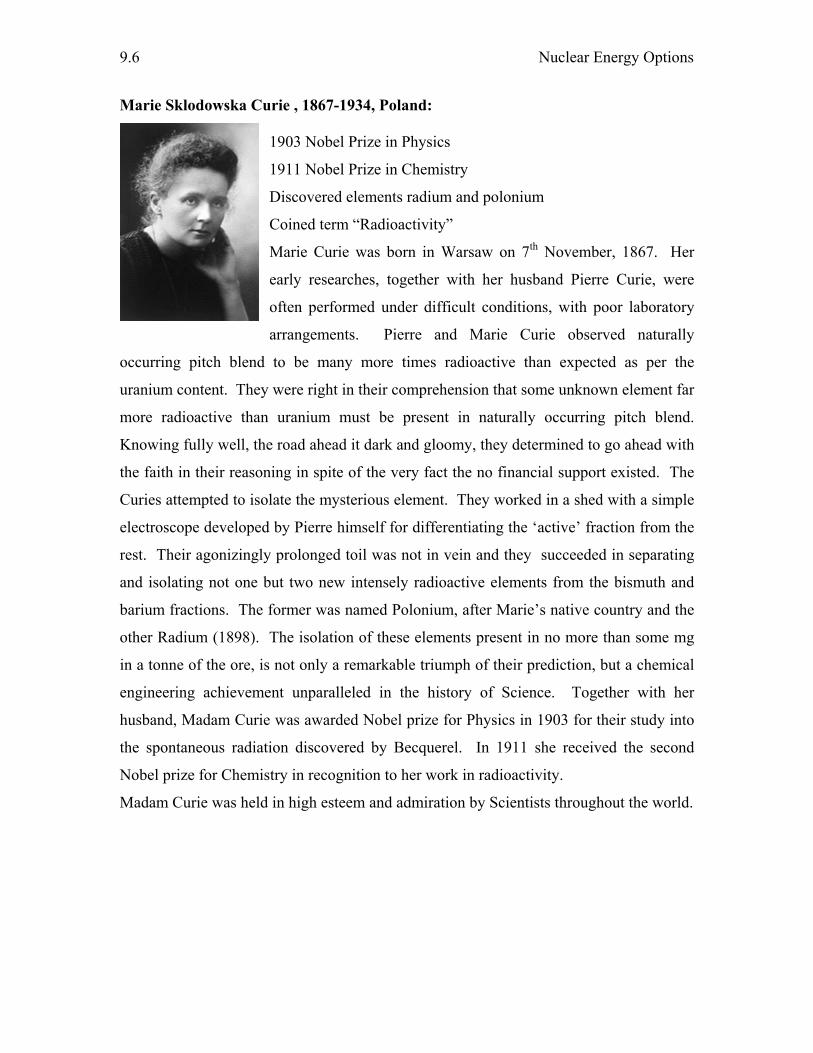
Nuclear Energy Options
9.6
Marie Sklodowska Curie , 1867-1934, Poland: 1903 Nobel Prize in Physics
1911 Nobel Prize in Chemistry
Discovered elements radium and polonium
Coined term “Radioactivity”
Marie Curie was born in Warsaw on 7th November, 1867. Her
early researches, together with her husband Pierre Curie, were
often performed under difficult conditions, with poor laboratory
arrangements. Pierre and Marie Curie observed naturally
occurring pitch blend to be many more times radioactive than expected as per the
uranium content. They were right in their comprehension that some unknown element far
more radioactive than uranium must be present in naturally occurring pitch blend.
Knowing fully well, the road ahead it dark and gloomy, they determined to go ahead with
the faith in their reasoning in spite of the very fact the no financial support existed. The
Curies attempted to isolate the mysterious element. They worked in a shed with a simple
electroscope developed by Pierre himself for differentiating the ‘active’ fraction from the
rest. Their agonizingly prolonged toil was not in vein and they succeeded in separating
and isolating not one but two new intensely radioactive elements from the bismuth and
barium fractions. The former was named Polonium, after Marie’s native country and the
other Radium (1898). The isolation of these elements present in no more than some mg
in a tonne of the ore, is not only a remarkable triumph of their prediction, but a chemical
engineering achievement unparalleled in the history of Science. Together with her
husband, Madam Curie was awarded Nobel prize for Physics in 1903 for their study into
the spontaneous radiation discovered by Becquerel. In 1911 she received the second
Nobel prize for Chemistry in recognition to her work in radioactivity.
Madam Curie was held in high esteem and admiration by Scientists throughout the world.
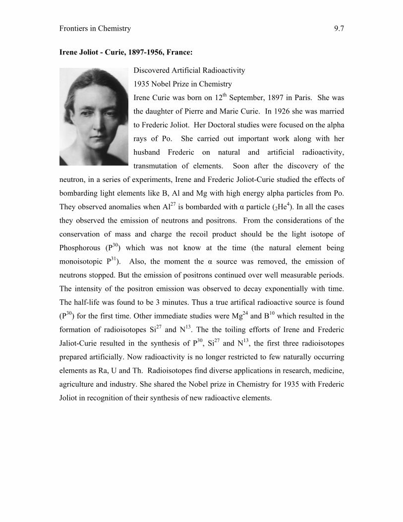
Frontiers in Chemistry
9.7
Irene Joliot - Curie, 1897-1956, France: Discovered Artificial Radioactivity
1935 Nobel Prize in Chemistry
Irene Curie was born on 12th September, 1897 in Paris. She was
the daughter of Pierre and Marie Curie. In 1926 she was married
to Frederic Joliot. Her Doctoral studies were focused on the alpha
rays of Po. She carried out important work along with her
husband Frederic on natural and artificial radioactivity,
transmutation of elements. Soon after the discovery of the
neutron, in a series of experiments, Irene and Frederic Joliot-Curie studied the effects of
bombarding light elements like B, Al and Mg with high energy alpha particles from Po.
They observed anomalies when Al27 is bombarded with α particle (2He4). In all the cases
they observed the emission of neutrons and positrons. From the considerations of the
conservation of mass and charge the recoil product should be the light isotope of
Phosphorous (P30) which was not know at the time (the natural element being
monoisotopic P31). Also, the moment the α source was removed, the emission of
neutrons stopped. But the emission of positrons continued over well measurable periods.
The intensity of the positron emission was observed to decay exponentially with time.
The half-life was found to be 3 minutes. Thus a true artifical radioactive source is found
(P30) for the first time. Other immediate studies were Mg24 and B10 which resulted in the
formation of radioisotopes Si27 and N13. The the toiling efforts of Irene and Frederic
Jaliot-Curie resulted in the synthesis of P30, Si27 and N13, the first three radioisotopes
prepared artificially. Now radioactivity is no longer restricted to few naturally occurring
elements as Ra, U and Th. Radioisotopes find diverse applications in research, medicine,
agriculture and industry. She shared the Nobel prize in Chemistry for 1935 with Frederic
Joliot in recognition of their synthesis of new radioactive elements.
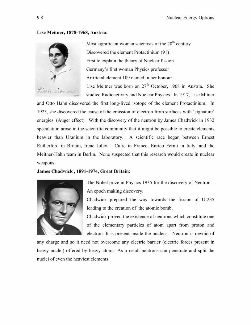
Nuclear Energy Options
9.8
Lise Meitner, 1878-1968, Austria: Most significant woman scientists of the 20th century
Discovered the element Protactinium (91)
First to explain the theory of Nuclear fission
Germany’s first woman Physics professor
Artificial element 109 named in her honour
Lise Meitner was born on 27th October, 1968 in Austria. She
studied Radioactivity and Nuclear Physics. In 1917, Lise Mitner
and Otto Hahn discovered the first long-lived isotope of the element Protactinium. In
1923, she discovered the cause of the emission of electron from surfaces with ‘signature’
energies. (Auger effect). With the discovery of the neutron by James Chadwick in 1932
speculation arose in the scientific community that it might be possible to create elements
heavier than Uranium in the laboratory. A scientific race began between Ernest
Rutherford in Britain, Irene Joliot – Curie in France, Enrico Fermi in Italy, and the
Meitner-Hahn team in Berlin. None suspected that this research would create in nuclear
weapons.
James Chadwick , 1891-1974, Great Britain: The Nobel prize in Physics 1935 for the discovery of Neutron –
An epoch making discovery.
Chadwick prepared the way towards the fission of U-235
leading to the creation of the atomic bomb.
Chadwick proved the existence of neutrons which constitute one
of the elementary particles of atom apart from proton and
electron. It is present inside the nucleus. Neutron is devoid of
any charge and so it need not overcome any electric barrier (electric forces present in
heavy nuclei) offered by heavy atoms. As a result neutrons can penetrate and split the
nuclei of even the heaviest elements.

Frontiers in Chemistry
9.9
Enrico Fermi, 1901-1954, Italy:
The Nobel prize in Physics 1938
Evolved the theory of ß-decay, 1934
First to device and design an atomic pile
Enrico Fermi was born in Rome on 29th September 1901. He was
awarded the Nobel prize in Physics 1938 for his demonstrations of
the existence of new radio active elements produced by neutron
irradiation and for his related discovery of nuclear reactions
brought about by slow neutrons. He evolved the β-decay theory in 1934. He
demonstrated that nuclear transformations occur in almost every element subjected to
neutron bombardment. He saw the possibility of emission of secondary neutrons and of a
chain reaction. He has proceeded to work with tremendous enthusiasm which ultimately
led to the atomic pile and the first controlled nuclear chain reaction.
Glenn Theodore Seaborg, 1893-1981, USA: The Nobel prize in Chemistry 1951
G. T. Seaborg was born in Rome on 29th September 1901.
He was co-discoverer of Plutonium and all further
transuranium elements through element 102. Seaborg and his
colleagues are responsible for the identification of more than
100 isotopes of elements through out the periodic table.He was
awarded Nobel prize in Chemistry for the discovery of the
transuranic elements.
Homi J Bhabha, 1909 – 1966, India: Homi Jehangir Bhabha is the Architect of India's Nuclear
Programme. He is an outstanding scientist and a brilliant
Engineer. Bhabha was indeed a perfectionalist. This worthy
son of Mother India was born on 30th October, 1909.
In the words of the inventor of Cloud Chamber C.T.R.
Wilson: “Scientist, engineer, master-builder and
administrator, steeped in humanities, in art and music, Homi

Nuclear Energy Options
9.10
was a truly complete man."
The name 'Meson' now used for a class of elementary particles (new particle found in
cosmic radation with a mass intermediate between that of electron and the proton), was
infact suggested by Bhabha. He established two great research institutions namely the
TIFR and BARC and from this we can know how great visionary he was.
To remember his own views about life let us look at a quote of Bhabha.
"I know quite clearly what I want of my life. Life and my emotions are the only things I
am conscious of. I love the consciousness of life and I want as much of it as I can get. But
the span of one's life is limited. What comes after death no one knows. Nor do I care.
Since, therefore, I cannot increase the content of life by increasing its duration, I will
increase it by increasing its intensity. Art, music ,poetry and every thing else that
consciousness I do have this one purpose - increasing the intensity of my consciousness
of life." Unfortunately Bhabha died prematuredly in a suspicious air crash on Mount
Blanc on 24th January, 1966. It was indeed an irreparable loss to the Nation as a whole.
A. P. J. Abdul Kalam, (1931 - ), India: Avul Pakir Jainulabdeen Abdul Kalam, the most distinguished
scientist of India was born on 15th October, 1931 at
Rameswaram in Tamil Nadu. He got specialized in
Aeronautical Engineering from Madras Institute of Technology.
He mastered himself in missile launch vehicle technology. He
led to the weaponisation of strategic missile systems and the
Pokhran – II nuclear tests which made India a nuclear weapon
state. He took up a mission to ignite the young minds for
national development by meeting high school students across the country. Dr. Kalam
became the 11th president of India. He received the highest civilian award Bharat Ratna in
the year 1997.
India’s Nuclear Polocy: Our policy is based on complete disarmament and no first use. India has always stood for
nuclear non-proliferation and its nuclear programme was meant for peaceful purposes in
the field of energy for civil purposes, agriculture, medicine and research.
Frontiers in Chemistry
9.11
Nuclear Reactions:
Nuclei remain intact in a vast majority of chemical reactions. Some space should be
devoted here for Alchemy and Alchemists since modern Chemistry has originated from
Alchemy. Alchemy is as old as human civilization. The Greek word ‘chemia’ appeared
in the fourth century. Later Arabic prefix ‘al’ was added to it. Thus the word Alchemy
signifies art of chemistry in general. Alchemy was a mixture of mystical, speculative
thought and practical laboratory techniques of chemistry and metallurgy. The main aim
of Alchemists was the transformation of base metals in to silver and gold (artificial
transmutation) which can in no way achieved by any of the known chemical reactions.
Development and understanding of Nuclear Science made it possible to artificially
transmute one element in to another. It is now known that a few nuclei under ordinary
conditions, and all nuclei under special conditions, undergo changes leading to nuclear
reactions. Such reactions in which nucleus of an itself undergoes spontaneous change or
interact with other nuclei of lighter particles resulting new nuclei and one or more lighter
particles are called nuclear reactions. There are striking differences between ordinary
chemical reactions and nuclear reactions and the differences are summarized below.
i. Chemical reactions depend upon the number of extra electron while nuclear
reactions are independent of the electrons but depend on the nature of the
nucleus.
ii. Chemical reactions involve some loss, gain or overlap of outer orbital electron
of the two reactant atoms. Nuclear reactions involve emission of some light
particles (α, β, positron and few others) from the nucleus of the atom to form
another element.
iii. The chemical reactivity of an element is dependent on the nature of the bond
present in the concerned compound. Where as the nuclear reactivity of an
element is independent of its state of chemical combination. For instance,
radium whether present as such or in the form of its compound shows similar
radioactivity.
iv. A chemical reaction is balanced only in terms of mass where as a nuclear
reaction must be balanced in terms of both mass and energy.
Nuclear Energy Options
9.12
v. The energy change occurring in nuclear reactions is very high as compared to
that in chemical reactions. The energy involved in a chemical reaction is
expressed in kcal/mole where as in nuclear reactions the energy is expressed
in MeV per nucleus.
vi. The chemical reactions are dependent on temperature and pressure while the
nuclear reactions are independent of external conditions.
Energy from Nuclear Fission:
Among several nuclear reactions known, for instance, nuclear fission, nuclear fusion,
radioactive decay, artificial transmutation, photonuclear reactions, radiative capture,
evaporation, spallation and many others, nuclear fission has the greatest practical
significance and has been exploited to the greatest extent for energy related applications
relative to other reactions.
The staggering amount of energy released during the process of fission is illustrated
below with respect to the fission of 235U caused by thermal neutrons where in the fission
fragments are 95Mo and 139La. The exact mass numbers of reactants and products are
shown below each of the reactants and products.
92U235 + 0n1 → 42Mo95 + 57La139 + 2 0n1 + energy
235.0439 + 1.0087 94.9057+ 138.9061+2.0174
236.0526 235.8292
Mass loss, Δm = 0.2234 amu
Fission energy = 931 Δm = 208 MeV
From where thing figure 931 suddently appeared? What is special about it?
The energy equivalent to 1 atomic mass unit (amu) is 931 MeV.
The mass of standard carbon atom (6C12) is taken to be 12 amu.
So, mass of 6C12 atom = 12 amu
1 amu = 1/12 x mass of 6C12 atom
1 mole = 12 g
6.023 x 10²³ atoms = 12 g
1 atom = 12/6.023 x 1023 g
1 amu = 1/12 x 12/6.023 x 1023 g
= 1.66 x 10⁻²⁴ g = 1.66 x 10⁻²⁷ kg
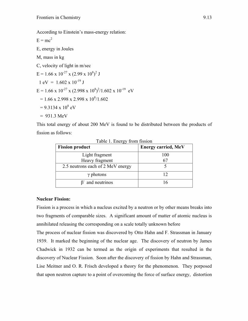
Frontiers in Chemistry
9.13
According to Einstein’s mass-energy relation:
E = mc2
E, energy in Joules
M, mass in kg
C, velocity of light in m/sec
E = 1.66 x 10-27 x (2.99 x 108)2 J
1 eV = 1.602 x 10⁻¹⁹ J
E = 1.66 x 10-27 x (2.998 x 108)2/1.602 x 10-19 eV
= 1.66 x 2.998 x 2.998 x 108/1.602
= 9.3134 x 10⁸ eV
= 931.3 MeV
This total energy of about 200 MeV is found to be distributed between the products of
fission as follows:
Table 1. Energy from fission Fission product Energy carried, MeV
Light fragment Heavy fragment
100 67
2.5 neutrons each of 2 MeV energy 5
γ photons 12 β- and neutrinos 16
Nuclear Fission:
Fission is a process in which a nucleus excited by a neutron or by other means breaks into
two fragments of comparable sizes. A significant amount of matter of atomic nucleus is
annihilated releasing the corresponding on a scale totally unknown before
The process of nuclear fission was discovered by Otto Hahn and F. Strassman in January
1939. It marked the beginning of the nuclear age. The discovery of neutron by James
Chadwick in 1932 can be termed as the origin of experiments that resulted in the
discovery of Nuclear Fission. Soon after the discovery of fission by Hahn and Strassman,
Lise Meitner and O. R. Frisch developed a theory for the phenomenon. They porposed
that upon neutron capture to a point of overcoming the force of surface energy, distortion
Nuclear Energy Options
9.14
of the excited nucleus takes place resulting in a splitting of the nucleus into fragments of
comparable masses [4].
The reaction of nuclear fission is schematically shown in Fig. 1. Fission occurs when
fissionable nucleus captures a neutron. The internal balance between neutrons and
protons in the nucleus is upset and it splits into two lighter nuclei. On the average 2-3
neutrons are emitted. The mass of the resulting products is less than the sum of the
masses of the original nucleus plus the captured neutron and the difference appears as
energy according to Einstein’s equation (E=Δmc2, where Δm is the mass loss involved in
a particular nuclear reaction, c is the velocity of light). If the released neutrons are
captured by other fissionable nuclei more fission events occur. When the reaction
becomes self-sustaining so that one fission triggers at least one more fission, the
phenomenon is termed as a chain reaction.
If the amount of U-235 is small, most of the neutrons will escape from the surface and the
reaction will stop. Therefore, a critical mass of metallic uranium is necessary in order to
start and sustain a chain reaction. The critical mass of U-235 has been found to be
between 1 to 100 kg.
The basic principle of an atomic bomb is the chain reaction. At the time of explosion two
samples each of subcritical mass, but whose total mass exceeds the critical mass, are
brought together by the use of ordinary explosives. Once these subcritical masses come
together, a chain reaction starts releasing a large amount of energy. One gram of U-235
evolves upon fission about 2 x 10⁷ kcal of energy.
Let us take the fissionable nucleus, U235, as a specific example.
In general the fission reaction resulting from absorption of neutron by U235 can be
written as shown below. The two fission fragments are lebelled as F1 and F2 to indicate
that many possible ways of splitting do exist.
92U235 + 0n1 → A1F1Z1 + A2F2
Z2 + ΰ0n1 + energy
When uranium isotope – 235 is bombarded with slow neutrons, U236 is formed by the
capturing of neutron. The U236 being unstable break up into two fragments besides
releasing two or three neutrons.
92U235 + 0n1 → 92U236 → 56Ba141 (F2) + 36Kr92 (F1) + 2-3 0n1 + 200 MeV
92U235 + 0n1 → 92U236 → 54Xe139 + 38Sr95 + 2 0n1 + 200 MeV
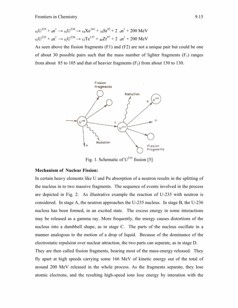
Frontiers in Chemistry
9.15
92U235 + 0n1 → 92U236 → 54Xe141 + 38Sr92 + 2 0n1 + 200 MeV
92U235 + 0n1 → 92U236 → 52Te137 + 40Zr97 + 2 0n1 + 200 MeV
As seen above the fission fragments (F1) and (F2) are not a unique pair but could be one
of about 30 possible pairs such that the mass number of lighter fragments (F1) ranges
from about 85 to 105 and that of heavier fragments (F2) from about 150 to 130.
Fig. 1. Schematic of U235 fission [5]
Mechanism of Nuclear Fission:
In certain heavy elements like U and Pu absorption of a neutron results in the splitting of
the nucleus in to two massive fragments. The sequence of events involved in the process
are depicted in Fig. 2. As illustrative example the reaction of U-235 with neutron is
considered. In stage A, the neutron approaches the U-235 nucleus. In stage B, the U-236
nucleus has been formed, in an excited state. The excess energy in some interactions
may be released as a gamma ray. More frequently, the energy causes distortions of the
nucleus into a dumbbell shape, as in stage C. The parts of the nucleus oscillate in a
manner analogous to the motion of a drop of liquid. Because of the dominance of the
electrostatic repulsion over nuclear attraction, the two parts can separate, as in stage D.
They are then called fission fragments, bearing most of the mass-energy released. They
fly apart at high speeds carrying some 166 MeV of kinetic energy out of the total of
around 200 MeV released in the whole process. As the fragments separate, they lose
atomic electrons, and the resulting high-speed ions lose energy by interation with the
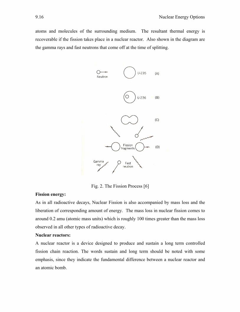
Nuclear Energy Options
9.16
atoms and molecules of the surrounding medium. The resultant thermal energy is
recoverable if the fission takes place in a nuclear reactor. Also shown in the diagram are
the gamma rays and fast neutrons that come off at the time of splitting.
Fig. 2. The Fission Process [6]
Fission energy:
As in all radioactive decays, Nuclear Fission is also accompanied by mass loss and the
liberation of corresponding amount of energy. The mass loss in nuclear fission comes to
around 0.2 amu (atomic mass units) which is roughly 100 times greater than the mass loss
observed in all other types of radioactive decay.
Nuclear reactors:
A nuclear reactor is a device designed to produce and sustain a long term controlled
fission chain reaction. The words sustain and long term should be noted with some
emphasis, since they indicate the fundamental difference between a nuclear reactor and
an atomic bomb.
Frontiers in Chemistry
9.17
Fissioning of a gram of uranium yields approximately one million times as much energy
as is released by the same quantity of uranium undergoing a chemical reaction , eg.
oxidation. This comparison between nuclear energy and chemical energy is a major
feature unique to nuclear reactors.
There is only one naturally occurring isotope which fissions readily. This is the
isotope of uranium having an atomic weight of 235. It constitutes about 0.7% of natural
uranium (balance U-238). There are two other fissionable isotopes of practical interest ,
Pu-239 and U-233 which can be produced as a result of neutron reactions with U-238 and
Th-232 respectively.
Components and materials of Nuclear Reactors:
In brief, the lighter elements such as H, Be and C act as suitable neutron moderators.
Most of the elements near the centre of the periodic table appear as fission products. The
heavier elements are either potential nuclear fuels or are produced by neutron capture in
the fuel during operation of a reactor. Many of the transition metals make suitable
construction or container materials for nuclear reactors. Many elements such as fluorine,
as UF6, find a unique application in the industry. An elaborate account of the
components of the nuclear reaction are placed below:
The Fuel:
Special nuclear material (SNM) – Where does it come from?
SNM is defined by Title I of the atomic energy act of 1954 as Pu, U-233 or uranium
enriched in the isotopes of U-233 or U-235. The definition includes any other material
which the commission determines to be special nuclear material, but does not include
source material.
U-233 and Pu-239 do not occur naturally. They can be formed in nuclear reactors and
extracted from the highly radioactive spent fuel by chemical separation. U-233 can be
produced in special reactors that use Thorium as fuel. Pu-239 can be produced in
reactors using U-238 or U-235 fuel. Uranium enriched in uranium 235 is created by an
enrichment facility. U-233 is an entirely man-made isotope. Its importance stems from
the fact that it has a high cross section for fission by thermal neutrons. Its fission cross
sections are comparable to that of the other fissile nuclides like U-235 and U-239. The
Nuclear Energy Options
9.18
precursor for U-233 is the widely occurring monoisotopic Th-232. India has an abundant
supply of Th-232 in the form of rich monazite sand of kerala.
Plutonium – Why do world nations crave for this?
Plutonium (Pu) is strategically the most important element of the 20th century. It is
entirely man-made atom by atom, first in μg and now in kg amounts and stockpiled in
tones, in subcritical amounts.
U238 + 0n1 → U239 (β decay) → Np239 (β decay) → Pu239 (α emitter, half life = 2.4 x 10⁴
years) → U235
Pu-239 is employed as nuclear fuel on account of its high neutron absorption cross
section (cross section for fission by thermal neutrons). It is used as fuel in fast breeder
reactor, where it is bred from U238. It is used as an atom bomb element.
Uranium enrichment:
Three isotopes of uranium occur naturally and their relative abundances (in atomic
percent) are as follows:
92U234 (light weight atom) - 0.006%
92U235 (middle weight atom) - 0.714%
92U238 (heavy atom) - 99.28%
The fuel for nuclear reactors has to have a higher concentration of uranium-235 than
exists in natural uranium ore. This is because U-235 is the key ingredient that starts a
nuclear reactor and keeps it going. Normally, the amount of U-235 isotope is enriched
from 0.7 % of uranium mass to 5 %. Several different processes are used to enrich
uranium. The important methods among them being Gas diffusion and Gas centrifuge.
Separation of U-235 from natural uranium is an outstanding example of isotope
separation. The separation process relies upon the slight difference in the rate of
diffusion through a membrane (Graham’s law of diffusion) of the hexafluorides namely
U235F6 and U238F6 . Fortunately the situation is not complicated by the variation in the
isotopic weights of fluorine since the only naturally occurring isotope of fluorine is F19.
Gas diffusion method:
In the gaseous diffusion enrichment plant, the solid uranium hexafluoride (UF6) from the
conversion process is heated in its container until it becomes a liquid. The container
becomes slightly pressurized as the solid melts. Because the container is not completely
Frontiers in Chemistry
9.19
full UF6 gas then fills the top of the container. The UF6 gas is slowly fed into the plant’s
pipelines where it is pumped through special filters called barriers or porous membranes.
The holes in the barriers are so small that there is barely enough room for the UF6 gas
molecules to pass through. The isotope enrichment occurs when the lighter UF6 gas
molecules (with the U-234 and U-235 atoms) tend to diffuse faster through the barriers
than the heavier UF6 gas molecules containing U-238. One barrier is not enough to do
the job. It takes many hundreds of barriers, one after the other, before the UF6 gas
contains enough U-235 to be used in reactors. At the end of the process, the enriched
UF6 gas is with drawn from the pipelines and condensed back into a liquid that is poured
into containers. The UF6 is then allowed to cool and solidify before it is transported to
fuel fabrication facilities where it is turned into fuel assemblies for nuclear power
reactors.
Gas centrifugation method:
The gas centrifuge uranium enrichment process uses a large number of rotating cylinders
in a series. These series of centrifuge machines, called trains. They are interconnected to
form cascades. In this process, uranium hexafluoride (UF6) gas is placed in a rotating
drum or cylinder and rotated at a high speed. This rotation creates a strong gravitional
field so that the heavier gas molecules (with U-238) move toward outside (out let at the
bottom) of the cylinder and the lighter gas molecules (containing U-235) collected closer
to the centre. The stream that is slightly enriched in U-235 is withdrawn and fed into
next higher stage, while the slightly depleted stream is recycled back into the next lower
stage. Significantly more U-235 enrichment can be obtained from a single unit gas
centrifuge than from a single unit gaseous diffusion barrier.
Moderator:
Material which helps the neutrons lose energy and keeps them in custody until they are
relatively safe from capture by U-238 is known as moderator. It is obvious that the
moderator must not absorb too many neutrons or the reaction will stop. Fast neutons
released by fission are not as easy to catch as are slower neutrons, so we allow them to
wander around in the moderator and reduce their energy to that corresponding to the
ambient temperature. These neutrons are then in thermal equilibrium with the atoms or
molecules of the moderator. Such neutrons are called thermal neutrons and have kinetic
Nuclear Energy Options
9.20
energies in the order of 0.025 eV, implying a speed of about 5000 mph. The probability
that a U-235 nucleus will fission is about 300 times greater with a slow (thermal) neutron
than with a fast neutron. In more technical terms, it can be stated that the fission cross-
section of natural uranium increases from about 0.015 barn at a neutron energy of 1 MeV
to 3.9 barn at thermal neutron energy. Thus to produce a neutron chain reaction in
natural uranium it is necessary to add a moderating material which will slow down the
neutrons by collision with the moderator nuclei. Suitable moderators are light and heavy
water, carbon (graphite), beryllium, and beryllium compounds.
The most widely used moderators are heavy water (D2O) and graphite. Light water can
be used but it has high neutron absorption cross section compared to deuterium. When
D2O is moderator, since the neutron absorption cross section is low, the U-235 content of
the fuel is correspondingly smaller.
Natural graphite has a density of 2.26 g/cc where as artificial graphite has a lower density
of 1.6 – 1.7 g/cc. This lower density implies a comparatively high porosity.
Unfortunately, this is a considerable disadvantage since the amount of surface available
for oxidation reactions is increases.
Nuclear Reactors – Control:
Safety is given no less priority in the design and fabrication of the Nuclear reactors meant
for a sustained chain reaction. In this regard, Control rods play a prominant role. It can be
regarded as one of the poisons towards neutrons and these can be employed at the call of
the situation. They have great capacity to absorb neutrons. They are arrestors of
neutrons. The number of fissions occurring per second in the nuclear reactions and thus
the chain reactions can be regulated by adjusting the position of these rods.
What materials can function as control rod poisons ?
What criteria a given material has to satisfy for it to be employed as a control rod ?
The major requirements that should be satisfied are. high neutron absorption, adequate
strength, low mass (for rapid movement), corrosion resistance, stability under heat and
radiation and satisfactory heat-trasfer properties.
The possible materials for control rods are :
Boron, Cadmium, Hafnium, Rare earths, Europium, Gadolinium, Samarium,
Dysprosium, Erbium and Lutetium. Elements with relatively high thermal neutron
Frontiers in Chemistry
9.21
absorption cross section are Cd (2400 barns), Boron (750 barns), Hafnium (115 barns),
Iridium (440 barns), Mercury (300 barns), and mixtures of rare earths. Because Hafnium,
Indium and the rare earths were quite expensive and Mercury presented engineering
difficulties early emphasis was on Cd and B.
Unfortunately, neither of these, in elemental form , meets all the requirements. In more
recent years, interest in Hf and the rare earths has greatly increased.
The Hafnium:
Hafnium is found associated with Zirconium in all its minerals, and is normally obtained
by removing it from Zr. In general Hafnium is similar to Zr and Ti in its properties,
corrosion resistance, fabrication etc. Unlike Zr, however, it is not sensitive to small
amounts of impurities such as Nitrogen. Although the thermal neutron absorption cross
section is relatively low, Hf is highly effetive as a control becasue of its large epithermal
resonance-capture crosss section. The major advantage of hafnium over B and Cd is that
is, doesn't need to be incorporated in some other materials, since it has more than
adequate strength and stability in itself.
Coolants:
The heat produced in the reactor is extrated out by coolants. The heat can be used to
convert water to high pressure steam which drives the turbine and the latter in turn drives
the generator. Light water, CO2, Helium and liquid sodium can be used as coolants.
Classification of Nuclear Reactors:
Depending on the purpose, neutron energy, moderator and coolant, fuel arrangement and
structure materials reactors can be classified into various types the main purpose being
power, research, breader and so on.
Depending on the energy of the neutron used to induce fission the reactors can be
classified into either fast reactor or thermal reactors. In a fast reactor most of the
neutrons are in the energy range of 0.1 – 1 MeV. The neutron remain at high energy
because there is relatively little material present to cause them to slow down. In contrast,
thermal reactor contains a good neutron moderating material. In these reactors, the bulk
of the neutrons have energy in the vicinity of 0.1 eV.
Nuclear power plants:
Nuclear Energy Options
9.22
The talk of building Nuclear power plants is reviving world over because of their low
emissions of green house gases in the generation process. Nuclear energy is a way to
generate heat using the fission process of atoms . A Nuclear power plant converts the heat
into electricity. The purpose of a nuclear power plant is to produce or release heat and
boil water. It is designed to produce electricity. It should be noted that while there are
significant differences, there are many similarities between power plants and other
electrical generating facilities. Uranium is used for fuel, in general, in nuclear power
plants to make electricity. The main difference between a nuclear power plant and other
kinds of power plants (coal, oil, gas ) is that at a nuclear plant , the heat used to make the
steam is produced by fissioning atoms. Fission is the splitting of atoms into smaller
pieces, caused by neutrons. These smaller pieces (in crude terminology) strike other
atoms, releasing energy. When this process continues it is called a chain reaction.
Broadly there are three types of nuclear power plant reactors, namely, burner reactors,
converter reactors, and breeder reactors.
Both Pressurized water reactors and boiling water reactors are two types of light water
reactors.
Breeder reactors:
Breeder reactors produce more fissionable material than they consume. Breeder fuel
consists of a mixture of both fertile (U238 , Th232) and fissile ((Pu239 , U233) materials. The
number of neutrons released is sufficient to propagate the fission reaction and to produce
more fissionable materials (Pu239) by the conversion of fertile isotopes to fissile isotopes.
Principle of breeding:
As seen above an appropriate mixture of Pu239(U233) and U238(Th232) should be employed
as fuel in breeder reactors. Let us consider one such reactor. It is possible to create
conditions such that out of the three neutrons released from the fission of each fissile
atom (Pu239 or U233) one of the neutrons is used up in propagating the fission chain by
interacting with other fissile atom (Pu239 or U233). At the same time the remaining two
neutrons will be available for transmuting U238 or Th232 in to two new fissile atoms of
Pu239 or U233 by the reactions shown below.
92U238 + 0n1 → 92U239 (β decay) → 93Np239 (β decay) → 94Pu239
90Th232 + 0n1 → 90Th233 (β decay) → 91Pa233 (β decay) → 92U233
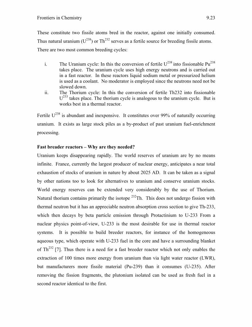
Frontiers in Chemistry
9.23
These constitute two fissile atoms bred in the reactor, against one initially consumed.
Thus natural uranium (U238) or Th232 serves as a fertile source for breeding fissile atoms.
There are two most common breeding cycles:
i. The Uranium cycle: In this the conversion of fertile U238 into fissionable Pu238 takes place. The uranium cycle uses high energy neutrons and is carried out in a fast reactor. In these reactors liquid sodium metal or pressurized helium is used as a coolant. No moderator is employed since the neutrons need not be slowed down.
ii. The Thorium cycle: In this the conversion of fertile Th232 into fissionable U233 takes place. The thorium cycle is analogous to the uranium cycle. But is works best in a thermal reactor.
Fertile U238 is abundant and inexpensive. It constitutes over 99% of naturally occurring
uranium. It exists as large stock piles as a by-product of past uranium fuel-enrichment
processing.
Fast breader reactors – Why are they needed?
Uranium keeps disappearing rapidly. The world reserves of uranium are by no means
infinite. France, currently the largest producer of nuclear energy, anticipates a near total
exhaustion of stocks of uranium in nature by about 2025 AD. It can be taken as a signal
by other nations too to look for alternatives to uranium and conserve uranium stocks.
World energy reserves can be extended very considerably by the use of Thorium.
Natural thorium contains primarily the isotope 232Th. This does not undergo fission with
thermal neutron but it has an appreciable neutron absorption cross section to give Th-233,
which then decays by beta particle emission through Protactinium to U-233 From a
nuclear physics point-of-view, U-233 is the most desirable for use in thermal reactor
systems. It is possible to build breeder reactors, for instance of the homogeneous
aqueous type, which operate with U-233 fuel in the core and have a surrounding blanket
of Th232 [7]. Thus there is a need for a fast breeder reactor which not only enables the
extraction of 100 times more energy from uranium than via light water reactor (LWR),
but manufacturers more fissile material (Pu-239) than it consumes (U-235). After
removing the fission fragments, the plutonium isolated can be used as fresh fuel in a
second reactor identical to the first.
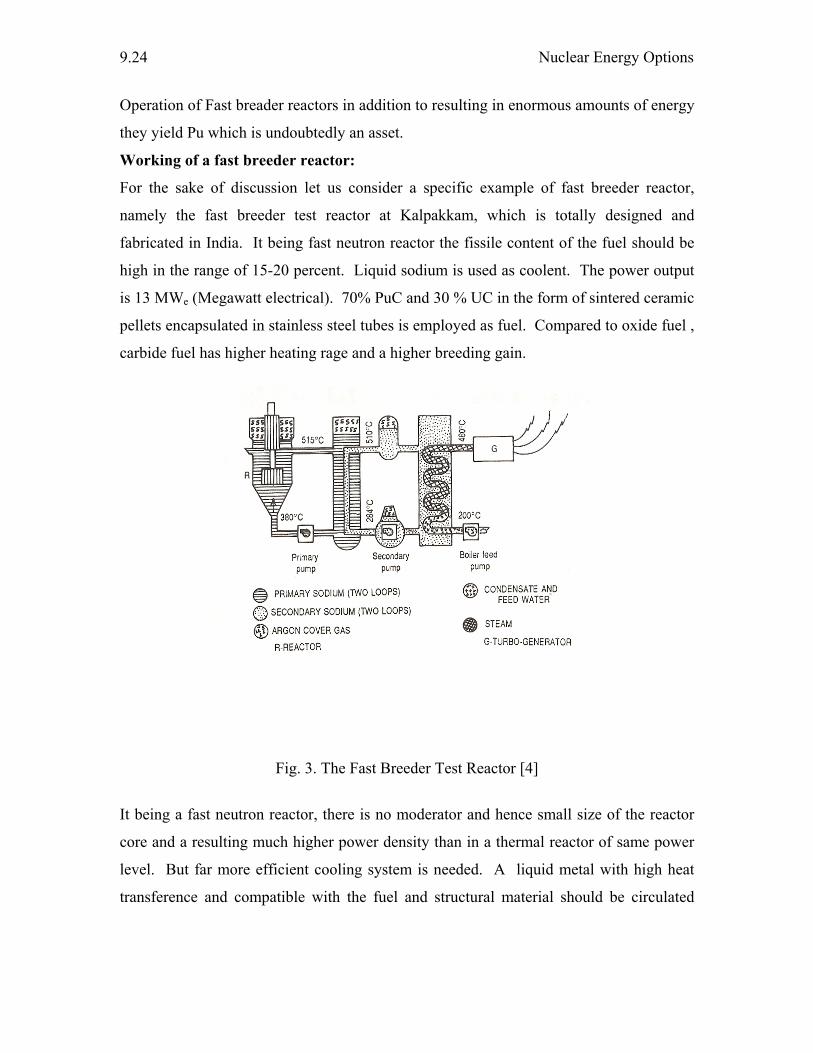
Nuclear Energy Options
9.24
Operation of Fast breader reactors in addition to resulting in enormous amounts of energy
they yield Pu which is undoubtedly an asset.
Working of a fast breeder reactor:
For the sake of discussion let us consider a specific example of fast breeder reactor,
namely the fast breeder test reactor at Kalpakkam, which is totally designed and
fabricated in India. It being fast neutron reactor the fissile content of the fuel should be
high in the range of 15-20 percent. Liquid sodium is used as coolent. The power output
is 13 MWe (Megawatt electrical). 70% PuC and 30 % UC in the form of sintered ceramic
pellets encapsulated in stainless steel tubes is employed as fuel. Compared to oxide fuel ,
carbide fuel has higher heating rage and a higher breeding gain.
Fig. 3. The Fast Breeder Test Reactor [4]
It being a fast neutron reactor, there is no moderator and hence small size of the reactor
core and a resulting much higher power density than in a thermal reactor of same power
level. But far more efficient cooling system is needed. A liquid metal with high heat
transference and compatible with the fuel and structural material should be circulated
Frontiers in Chemistry
9.25
along the primary and secondary loops depicted in Fig. 3. In general low melting point
metals like 7Li and 23Na were proved to be the best.
A sodium pump drives the liquid metal at 380 ºC into the reactor core from below. When
the liquid leaves at the top at 515 ºC much heat would have been extracted from the
reactor core. By this time Na23 becomes radioactive Na24 by (n, γ) reaction. Being
radioactive the primary sodium is made to transfer the heat to a sealed second loop of
sodium as an intermediate heat exchanger which remains non-radioactive. The two
sodium pumps are of special design to keep circulating some 150 tons of molten sodium
in the two mutually isolated loops. Thus the activity of the first loop is wholly contained
therein. The heat from the secondary sodium loop is finally transferred to a boiler. The
steam generated at 480 ºC and 125 kg/cm pressure drives a steam turbine to generate
electricity. Thus the breeder reactor generates electricity.
Doubling time: The time needed to set up the second reactor is called the doubling time.
In other words, the time required to double the inventory of fissionable material.
Nuclear Fusion:
A thermonuclear reaction in which nuclei of lighter atoms combine to form nuclei of
heavier atoms accompanied by the release of large amount of energy is called a fusion
reaction.
The Sun – Is the sun truly an inexaustable source of energy? How?
Can there be an artificial sun?
Truly the light is sweet, and a pleasant thing it is for the eyes to behold the Sun: The Holy
Bible (Ecclesiastes 11:7)
Fusion reactions are considered to be responsible for the endless (currently assumed)
source of energy given out by the sun.
The sun keeps replenishing its energy because it is continuously supplied with atomic
energy from nuclear reactions going on in the interior, where the temperature is of the
order of 20 million degrees centigrade. The energy of the sun is supposed to arise from
the following thermo-nuclear reactions:
1H1 + 1H1 → 1H2 + e+ + Energy
1H2 + 1H1 → 2He3 + Energy
2He3 + 2He3 → 2He4 + 2 1H1 + Energy
Nuclear Energy Options
9.26
The net result of this reaction is the combination of four protons to produce one nucleus
of helium 2He4 as represented below:
4 1H1 → 2He4 + 2 +e0
4 x 1.008144 4.003873 2 x 0.000558 = 0.001116
4.032576 4.004989
Mass loss, Δm = 4.032576 – 4.004989
= 0.027587 amu
Energy released = 0.027587 x 931 MeV = 26.7 MeV
Controlled nuclear fusion:
In sharp contrast to fission, nuclear fusion process could not be controlled. The estimated
amounts of deuterium in the water of the earth is 1017 pounds (1 kg = 2.2 pounds). Each
pound of deuterium is equivalent to 2500 tons of coal in energy. So a controlled fusion
reactor would provide a virtually inexhaustible supply of energy. Thus a great effort is
being made to build such a reactor. Success in this direction is not too far [8].
Obstacles in exploiting fusion energy:
i. Fuel : Attempts should be intensified to separate deuterium from ordinary
water. Production of tritium can also be attempted.
ii. The particles must be heated to temperatures ranging from 50 to 100 million
degrees depending upon the particular reaction.
iii. The state of plasma must be present for a long enough time so as to allow a
substantial portion of the nuclei present in it to undergo fission.
iv. Technology to harness the released energy to generate useful power also need
to mature.
The energy released is 26.7 MeV for four protons. The heat produced in these
thermonuclear reactions makes up the loss of heat by sun’s radiation there by keeping the
sun’s temperature constant.
Fusion reactions are used to make hydrogen bomb (thermonuclear bomb). The
technology of fusion bombs is different from that of fission bombs (atom bomb). Since
very high temperature is required to initiate the fusion reaction of the type 1H2 + 1H2 →
2He4, an atomic bomb is used as a trigger [9].
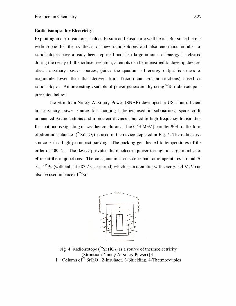
Frontiers in Chemistry
9.27
Radio isotopes for Electricity:
Exploiting nuclear reactions such as Fission and Fusion are well heard. But since there is
wide scope for the synthesis of new radioisotopes and also enormous number of
radioisotopes have already been reported and also large amount of energy is released
during the decay of the radioactive atom, attempts can be intensified to develop devices,
atleast auxiliary power sources, (since the quantum of energy output is orders of
magnitude lower than that derived from Fission and Fusion reactions) based on
radioisotopes. An interesting example of power generation by using 90Sr radioisotope is
presented below:
The Strontium-Ninety Auxiliary Power (SNAP) developed in US is an efficient
but auxiliary power source for charging batteries used in submarines, space craft,
unmanned Arctic stations and in nuclear devices coupled to high frequency transmitters
for continuous signaling of weather conditions. The 0.54 MeV β emitter 90Sr in the form
of strontium titanate (90SrTiO3) is used in the device depicted in Fig. 4. The radioactive
source is in a highly compact packing. The packing gets heated to temperatures of the
order of 500 ºC. The device provides thermoelectric power through a large number of
efficient thermojunctions. The cold junctions outside remain at temperatures around 50
ºC. 238Pu (with half-life 87.7 year period) which is an α emitter with energy 5.4 MeV can
also be used in place of 90Sr.
Fig. 4. Radioisotope (90SrTiO3) as a source of thermoelectricity
(Strontium-Ninety Auxilary Power) [4] 1 – Column of 90SrTiO3, 2-Insulator, 3-Shielding, 4-Thermocouples
Nuclear Energy Options
9.28
Such deivces are not risk free for enough care need to be taken such that no leak of encapsulation takes place. Conclusion:
The work of construction should not stop for fear of destruction. Let us go ahead with
the option of nuclear energy since the benefits and comforts derived there from out
weight the frustrations and fears of peril.
Wisdom is better than weapon of war: but one sinner destroyeth much good.
The Holy Bible (Ecclesiastes 9:18)
References: 1. B. Viswanathan, Editor, Chapter 4, Energy Sources – A Chemist’s Perspective,
2006, ebook available on www.nccr.iitm.ac.in.
2. http://forums.delphiforums.com/catalysisindia
3. R. K. Pachauri, Journal of the Petrotech Society, IV (1), 2007, 8
4. H. J. Arnikar, Essentials of Nuclear Chemistry, New age international (P) limited,
1995.
5. Marion L. Shepard, Jack B. Chaddock, Franklin H. Cocks, Charles M. Harman,
Introduction to Energy Technology, Ann Arbor Science, Publishers Inc, 1976.
6. Raymond I. Murray, Nuclear Energy, Pergamon unified engineering series, Pergamon
Press Inc., 1975
7. J. K. Dawson and G. Long, Chemistry of Nuclear Power
8. O. P. Agarwal, Unified Course in Chemistry, Volume III, Jai Prakash Nath & Co.
1990.
9. C. N. R. Rao, Editor, University General Chemistry, Macmillan
Chapter - 10 HYDROGEN ENERGY
L. Hima Kumar
Introduction
Energy is one of the most basic of human needs and is extremely crucial for continued
human development. The accomplishments of civilization have largely been achieved
through the increasingly efficient and extensive harnessing of various forms of energy to
extend human capabilities and ingenuity. Providing adequate and affordable energy is
essential for eradicating poverty, improving human welfare, and raising living standards
worldwide. The global demand for energy is rapidly increasing with increasing human
population, urbanization and modernization. The growth in global energy demand is
projected to rise sharply over the coming years. The world heavily relies on fossil fuels to
meet its energy requirements, fossil fuels such as oil, gas and coal. Presently employed
energy systems will be unable to cope with future energy requirements, fossil fuel
reserves are depleting, and predominantly the developed countries employ nuclear power.
Fossil fuel and nuclear energy production and consumption are closely linked to
environmental degradation that threatens human health and quality of life, and affects
ecological balance and biological diversity. It is therefore clear that if the rapidly
increasing global energy needs are to be met without irreparable environmental damage,
there will have to be a worldwide drive to exploit energy systems that should not
endanger the life of current and future generations and should not exceed the carrying
capacity of ecosystems.
One of the most significant transitions in global energy systems is that of
decarbonization, an increase in energy quality (Fig. 1). Considering the case of fossil
fuels, the dominating energy resource over the course of human history, each successive
transition from one source to another from wood to coal, from coal to oil has entailed a
shift to fuels that were not only harnessed and transported more economically, but also
had a lower carbon content and higher hydrogen content. It is also evident that at each
step greater energy density is being achieved. The third wave of decarbonization is now
at its threshold, with natural gas use growing fastest, in terms of use, among the fossil
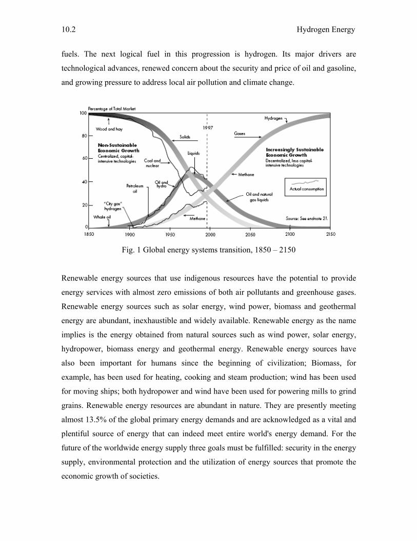
Hydrogen Energy
10.2
fuels. The next logical fuel in this progression is hydrogen. Its major drivers are
technological advances, renewed concern about the security and price of oil and gasoline,
and growing pressure to address local air pollution and climate change.
Fig. 1 Global energy systems transition, 1850 – 2150
Renewable energy sources that use indigenous resources have the potential to provide
energy services with almost zero emissions of both air pollutants and greenhouse gases.
Renewable energy sources such as solar energy, wind power, biomass and geothermal
energy are abundant, inexhaustible and widely available. Renewable energy as the name
implies is the energy obtained from natural sources such as wind power, solar energy,
hydropower, biomass energy and geothermal energy. Renewable energy sources have
also been important for humans since the beginning of civilization; Biomass, for
example, has been used for heating, cooking and steam production; wind has been used
for moving ships; both hydropower and wind have been used for powering mills to grind
grains. Renewable energy resources are abundant in nature. They are presently meeting
almost 13.5% of the global primary energy demands and are acknowledged as a vital and
plentiful source of energy that can indeed meet entire world's energy demand. For the
future of the worldwide energy supply three goals must be fulfilled: security in the energy
supply, environmental protection and the utilization of energy sources that promote the
economic growth of societies.
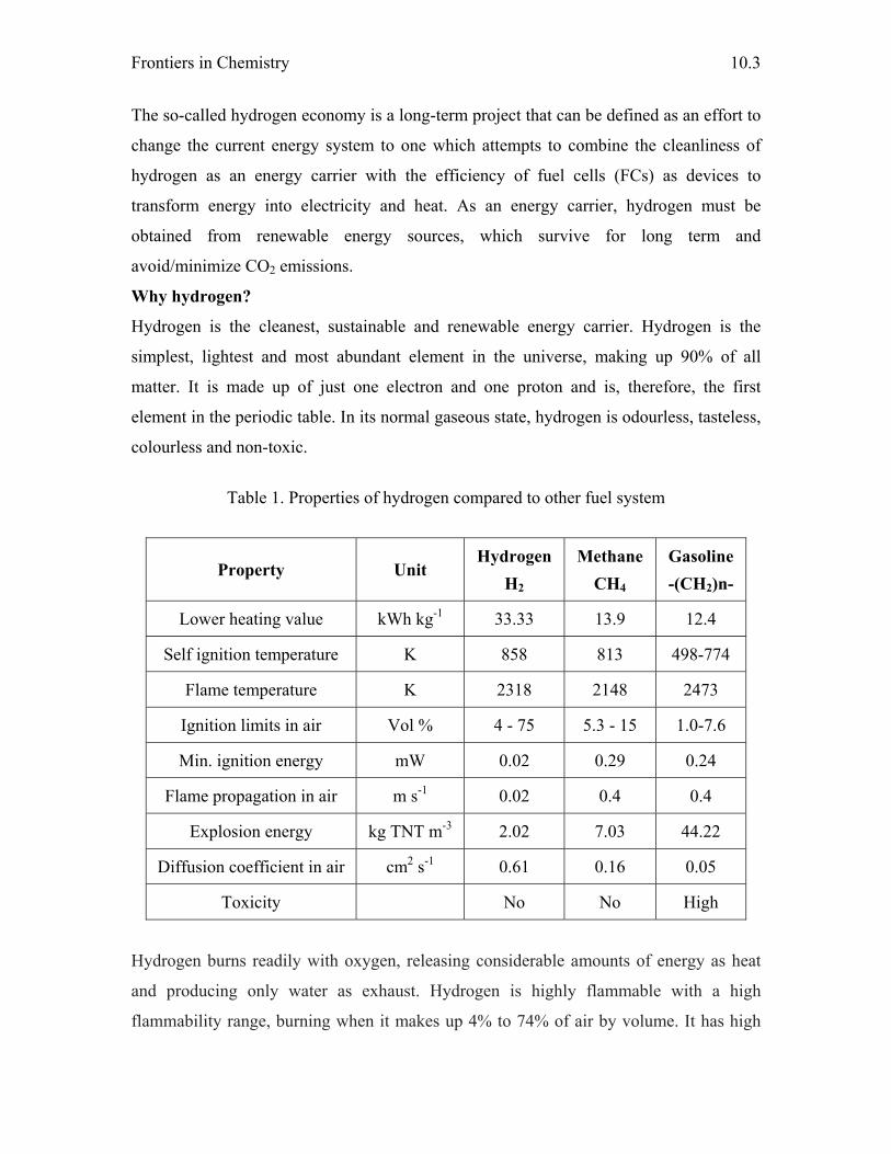
Frontiers in Chemistry
10.3
The so-called hydrogen economy is a long-term project that can be defined as an effort to
change the current energy system to one which attempts to combine the cleanliness of
hydrogen as an energy carrier with the efficiency of fuel cells (FCs) as devices to
transform energy into electricity and heat. As an energy carrier, hydrogen must be
obtained from renewable energy sources, which survive for long term and
avoid/minimize CO2 emissions.
Why hydrogen?
Hydrogen is the cleanest, sustainable and renewable energy carrier. Hydrogen is the
simplest, lightest and most abundant element in the universe, making up 90% of all
matter. It is made up of just one electron and one proton and is, therefore, the first
element in the periodic table. In its normal gaseous state, hydrogen is odourless, tasteless,
colourless and non-toxic.
Table 1. Properties of hydrogen compared to other fuel system
Property Unit Hydrogen
H2 Methane
CH4 Gasoline -(CH2)n-
Lower heating value kWh kg-1 33.33 13.9 12.4
Self ignition temperature K 858 813 498-774
Flame temperature K 2318 2148 2473
Ignition limits in air Vol % 4 - 75 5.3 - 15 1.0-7.6
Min. ignition energy mW 0.02 0.29 0.24
Flame propagation in air m s-1 0.02 0.4 0.4
Explosion energy kg TNT m-3 2.02 7.03 44.22
Diffusion coefficient in air cm2 s-1 0.61 0.16 0.05
Toxicity No No High
Hydrogen burns readily with oxygen, releasing considerable amounts of energy as heat
and producing only water as exhaust. Hydrogen is highly flammable with a high
flammability range, burning when it makes up 4% to 74% of air by volume. It has high
Hydrogen Energy
10.4
energy content by weight nearly three times that of gasoline. By contrast, hydrogen has a
low energy density by volume at a standard temperature and atmospheric pressure. One
gram of hydrogen gas at room temperature occupies about 11.2 liters of space. Storing
the gas under pressure or at temperatures below -253º C, at which point it turns into a
liquid, raises its volumetric density. In many ways hydrogen seems to be an attractive
replacement for existing fossil fuel system by their properties as given in Table 1.
Hydrogen is a carrier of energy, not a source. It does not exist in a natural state on
earth and must be manufactured using a hydrogen-rich compound such as water as the
raw material. Once it is extracted, becomes a useful “feedstock”, or input, to a variety of
industrial activities and sufficient to energize virtually all aspects of society, from homes
to electric utilities to business and industry to transportation
Hydrogen production
Hydrogen can be produced from a variety of feed stocks. These include fossil resources,
such as natural gas and coal, as well as renewable resources, such as biomass and water
with input from renewable energy sources (e.g. sunlight, wind, wave or hydro-power). A
variety of process technologies can be used, including chemical, biological, electrolytic,
photolytic and thermo-chemical. Each technology is in a different stage of development,
and each offers unique opportunities, benefits and challenges. Local availability of
feedstock, the maturity of the technology, market applications and demand, policy issues,
and costs will all influence the choice and timing of the various options for hydrogen
production. An overview of the various feed stocks and process technologies is presented
in Figure 2.
From fissile fuels
There are many industrial methods currently available for the production of hydrogen;
almost all the hydrogen produced in the world today involves the steam reforming of
fossil fuels using a nickel catalyst. At present, this is a proven, commercial technology
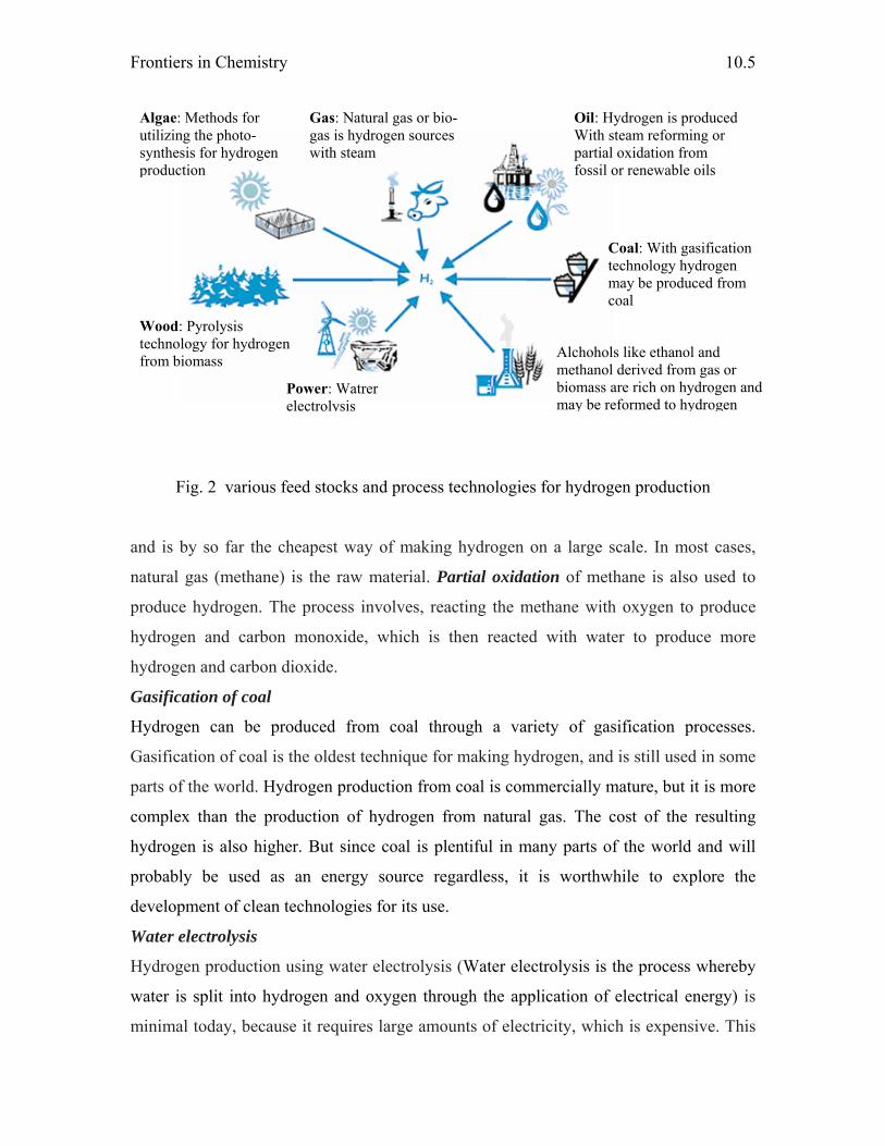
Frontiers in Chemistry
10.5
Fig. 2 various feed stocks and process technologies for hydrogen production
and is by so far the cheapest way of making hydrogen on a large scale. In most cases,
natural gas (methane) is the raw material. Partial oxidation of methane is also used to
produce hydrogen. The process involves, reacting the methane with oxygen to produce
hydrogen and carbon monoxide, which is then reacted with water to produce more
hydrogen and carbon dioxide.
Gasification of coal
Hydrogen can be produced from coal through a variety of gasification processes.
Gasification of coal is the oldest technique for making hydrogen, and is still used in some
parts of the world. Hydrogen production from coal is commercially mature, but it is more
complex than the production of hydrogen from natural gas. The cost of the resulting
hydrogen is also higher. But since coal is plentiful in many parts of the world and will
probably be used as an energy source regardless, it is worthwhile to explore the
development of clean technologies for its use.
Water electrolysis
Hydrogen production using water electrolysis (Water electrolysis is the process whereby
water is split into hydrogen and oxygen through the application of electrical energy) is
minimal today, because it requires large amounts of electricity, which is expensive. This
Oil: Hydrogen is produced With steam reforming or partial oxidation from fossil or renewable oils
Gas: Natural gas or bio-gas is hydrogen sources with steam
Wood: Pyrolysis technology for hydrogen from biomass
Algae: Methods for utilizing the photo-synthesis for hydrogen production
Alchohols like ethanol and methanol derived from gas or biomass are rich on hydrogen and may be reformed to hydrogen
Coal: With gasification technology hydrogen may be produced from coal
Power: Watrer electrolysis
Hydrogen Energy
10.6
technique is normally used only to produce hydrogen of very high purity, required in
some industrial processes, or other products, such as chlor-alkali, with hydrogen as a by-
product. But electrolysis could be used to produce small quantities of hydrogen close to
the point of use; for example, at refuelling stations. To be economic, the electricity would
need to be cheap. The environmental benefits of electrolysis-based hydrogen energy
depend on how the electricity is produced. If it were generated from nuclear or renewable
energy sources, such as wind, solar and biomass, electrolysis would produce carbon-free
hydrogen. But large reductions in the cost of renewables-based electricity and nuclear
power are needed to enable hydrogen produced by electrolysis to compete with
conventional sources of energy on a large scale.
Thermal decomposition of water
Direct decomposition of water to give hydrogen and oxygen occurs only at high
temperatures above 4000 K. To reduce the temperature, other processes for high
temperature splitting of water have been suggested. Even then, the splitting of water by
thermo-chemical methods requires temperatures around 1500 K. The thermochemical
cycles include the following: sulfuric acid–iodine cycle, hybrid sulfuric acid cycle, hybrid
sulfuric acid–hydrogen bromide cycle, calcium bromide–iron oxide cycle (UT-3), and
iron - chlorine cycle. Only, limited heat sources are available like nuclear reactor, which
can provide the required high temperature. The main problem of this method is related to
materials required for extremely high temperatures, recombination of the reaction
products at high temperatures, toxicity of some of the chemicals involved and separation
of hydrogen.
Biological or biochemical methods
The biological or biochemical methods for the production of hydrogen by splitting water
have also been under investigation. Micro organisms are capable of producing H2 via
either fermentation or photosynthesis. Photo-biological production of hydrogen is based
on two steps: photosynthesis and hydrogen production catalyzed by hydrogenases like
algae and cyanobacteria. In biomass conversion processes, a hydrogen-containing gas is
normally produced in a manner similar to the gasification of coal. However, no
commercial plants exist to produce hydrogen from biomass. Currently, the pathways
followed are steam gasification (direct or indirect), entrained flow gasification, and more
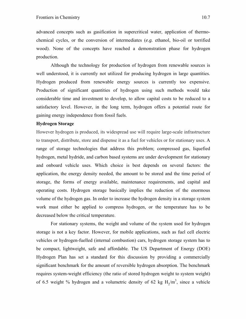
Frontiers in Chemistry
10.7
advanced concepts such as gasification in supercritical water, application of thermo-
chemical cycles, or the conversion of intermediates (e.g. ethanol, bio-oil or torrified
wood). None of the concepts have reached a demonstration phase for hydrogen
production.
Although the technology for production of hydrogen from renewable sources is
well understood, it is currently not utilized for producing hydrogen in large quantities.
Hydrogen produced from renewable energy sources is currently too expensive.
Production of significant quantities of hydrogen using such methods would take
considerable time and investment to develop, to allow capital costs to be reduced to a
satisfactory level. However, in the long term, hydrogen offers a potential route for
gaining energy independence from fossil fuels.
Hydrogen Storage
However hydrogen is produced, its widespread use will require large-scale infrastructure
to transport, distribute, store and dispense it as a fuel for vehicles or for stationary uses. A
range of storage technologies that address this problem; compressed gas, liquefied
hydrogen, metal hydride, and carbon based systems are under development for stationary
and onboard vehicle uses. Which choice is best depends on several factors: the
application, the energy density needed, the amount to be stored and the time period of
storage, the forms of energy available, maintenance requirements, and capital and
operating costs. Hydrogen storage basically implies the reduction of the enormous
volume of the hydrogen gas. In order to increase the hydrogen density in a storage system
work must either be applied to compress hydrogen, or the temperature has to be
decreased below the critical temperature.
For stationary systems, the weight and volume of the system used for hydrogen
storage is not a key factor. However, for mobile applications, such as fuel cell electric
vehicles or hydrogen-fuelled (internal combustion) cars, hydrogen storage system has to
be compact, lightweight, safe and affordable. The US Department of Energy (DOE)
Hydrogen Plan has set a standard for this discussion by providing a commercially
significant benchmark for the amount of reversible hydrogen absorption. The benchmark
requires system-weight efficiency (the ratio of stored hydrogen weight to system weight)
of 6.5 weight % hydrogen and a volumetric density of 62 kg H2/m3, since a vehicle
Hydrogen Energy
10.8
powered by a fuel cell would require more than 3.1 kg of hydrogen for a 500 km range.
Fig. 3 shows that various storage options that meet the long-term needs. To reach the
high volumetric and gravimetric density suitable for mobile applications, basically six
reversible storage methods are known today : 1) high- pressure gas cylinders, 2) liquid in
cryogenic tanks, 3) physisorbed on a solid surface e.g. carbon-nanotubes 4) metal
hydrides of the metals or intermetallic compounds. 5) complex hydrides of light elements
such as alanates and boranates, 6) storage via chemical reactions.
Fig. 3. Comparison of volumetric and gravimetric density of hydrogen with various storage media Compressed hydrogen gas
Gaseous hydrogen storage
The most common method to store hydrogen is as a compressed gas, either above or
below ground or on board vehicles. With a compressed gas system, the hydrogen is
typically compressed and stored in gas cylinders or spherical containers. For storing
hydrogen on board vehicles, compressed hydrogen is the simplest and presently the
cheapest method, requiring only a compressor and a pressure vessel. Its main obstacle is
its low storage density. Higher storage pressures raise the cost, as well as safety issues.

Frontiers in Chemistry
10.9
Liquid hydrogen
As an alternative to compression, hydrogen can be liquefied for storage in stationary or
onboard vehicle systems. Liquefaction takes place through a number of steps in which the
hydrogen is compressed and cooled to form a dense liquid. The liquid hydrogen must
then be stored at very low temperatures, below –250 °C. A major drawback with
liquefied hydrogen storage is the high cost of liquefaction and the significant liquid “boil
off”. Liquefying hydrogen gas also requires a large amount of electricity.
Solid hydrogen storage
Storage of hydrogen in solid materials has the potential to become a safe and efficient
way to store energy, both for stationary and mobile applications. There are four main
groups of suitable materials: carbon and other high surface area materials; H2O reactive
chemical hydrides; thermal chemical hydrides; and rechargeable hydrides.
Metal hydrides
Many metals and alloys are able to react spontaneously with hydrogen. These materials,
either a defined compound or a solid solution, are designed as metallic hydrides. These
are compounds that chemically bond the hydrogen in inter atomic lattice of a metal. The
hydrogen is absorbed into the lattice through cooling and released through heating, with
the temperature and pressure of these reactions depending on the particular makeup of the
hydride. Hydrides are unusual in that they can draw in the hydrogen at or below
atmospheric pressure, and release it at higher pressure when heated. Current drawbacks
of metal hydrides are that they are heavy, the gravimetric hydrogen density is limited to
less than 3 wt% of hydrogen, require energy to refill, and are comparatively costly.
Carbon nanostructures
Carbon-based systems are another strong hydrogen storage possibility in the early stages
of development. Scientists are working to develop materials that can store significant
amounts of hydrogen at room temperature, potentially a breakthrough that would enable
the practical use of hydrogen run vehicles. Two types are being explored. Single walled
carbon nanotubes, made up of molecule-sized pores and Graphite nanofibers, stacks of
nanocrystals that form a wall of similarly small pores. Even though the price of the
nanotubes and nanofibers is still high, they have a good potential in hydrogen storing and
Hydrogen Energy
10.10
will remain as materials that are competitive for to be used in hydrogen storage
processes.
Chemical hydrides
Chemical hydrides are also being considered for hydrogen storage on board vehicles.
Hydrogen may also be stored chemically in alkali metal hydrides. There are many options
in the alkali group like LiH, NaH, KH, CaH2. But also complex binary hydride
compounds like LiBH4, NaBH4, KBH4, LiAlH4 or NaAH4 are of interest and have been
proposed as hydrogen sources. None of these compounds can be found in nature. All
have to be synthesized from metals and hydrogen.
Chemicals such as methanol or ammonia could also be used which has the advantage of
an existing transport and storage infrastructure, a commercial technology, and relatively
easy liquid and storage handling.
Hydrogen application Residential and commercial applications:
Mixed with natural gas, hydrogen could be used in existing natural gas equipment. With
no change to the devices up to 3 % volume of hydrogen can be added to the gas. More
hydrogen requires modifications to the burners and other equipment of the consumer.
Industry
With proper adjustments all types of industrial natural gas burners can be fed with
hydrogen. Hydrogen could then be used as natural gas for steam generation. However in
order to maximize its energy efficiency, hydrogen is better used with fuel cells that
produce simultaneously heat and electricity (cogeneration).
Internal combustion engines and fuel cells
The key to the hydrogen energy system is using the fuel economically in internal
combustion engines, conventional combustion turbines, and fuel cells. Ongoing research
on hydrogen-fueled ICEs is aimed at use in vehicles. Hydrogen is a good fuel for internal
combustion (IC) engines and can improve efficiency by around 20% compared to the use
of gasoline. Several companies, such as Alstom, Westinghouse and Mitsubishi are
pursuing the use of hydrogen in gas turbines like those commercially established to run
on natural gas. A more likely long-term approach will be to employ hydrogen to run fuel
cells.
Frontiers in Chemistry
10.11
A fuel cell utilizes a chemical process to convert hydrogen (or a hydrogen-rich fuel) into
electrical energy and heat. It can do so at high efficiency (not subject to limitations of the
Carnot cycle), producing a non-fluctuating DC power output. Most fuel cells have high
power densities (i.e. high power output per unit weight, volume, or area). There are six
main types of fuel cell, distinguished by their different electrolytes and the different
temperatures reached during operation. Fuel cells display high efficiency across most of
their output power range whereas the internal combustion engine has a point of maximum
operating efficiency. The fuel cell has a very flat characteristic and is generally more
efficient at fractions of its rated power. As a consequence, the fuel cell will show even
larger advantages over an IC engine during a drive cycle compared to continuous output
tests.
The most commercially advanced version, the phosphoric acid fuel cell (PAFC)
run generally on either natural gas or propane or direct hydrogen and have been
purchased primarily for applications that produce both heat and power. Existing niche
markets include landfills, wastewater treatment plants, industrial food processors, high-
tech companies, banks, hospitals, and other facilities highly vulnerable to interruptions.
Two types of fuel cells must be operated at high temperatures, above 650 °C. These do
not require expensive catalysts, and their waste heat can be captured and used to run
turbines to increase overall efficiency to 60 percent or more, with the residual heat used
for space and water heating. Alkaline fuel cells, the type used in the Apollo program, are
being tested for commercial applications. Direct methanol fuel cells run on methanol
without need of a reformer. The fuel cell that is attracting the most attention is the proton
exchange membrane (PEM) fuel cell, used in the Gemini mission. This cell’s membrane
functions as an electrolyte through which protons pass, bonding with oxygen to form
water. This leaves the electrons to move along an external circuit, creating an electrical
current.
Future of hydrogen
Hydrogen has great potential as an environmentally clean energy fuel and as a way to
reduce reliance on imported energy sources. Before hydrogen can play a bigger energy
role and become a widely used alternative to gasoline, many new facilities and systems
must be built. We will need facilities to make hydrogen, store it, and move it. We will

Hydrogen Energy
10.12
need economical fuel cells. And consumers will need the technology and the education to
safely use it. The realization of this hydrogen economy largely depends on the
cooperation between the scientists for the development of new materials and
technologists to design appropriate devices and reactors so that this alternate form of
energy source can be utilized by mankind.
References
1. T. N. Veziroglu and F. Barbir, Int. J. Hydrogen Energy, 17 (1992) (6) 391
2. J. M. Ogden, Int. J. Hydrogen Energy, 24 (1999) (8) 709
3. S. Freni, G. Calogero and S. Cavallaro, J. Power Sources, 87 (2000) 28
4. J. Funk, Int. J. Hydrogen Energy, 26 (2001) 185
5. A. Zuttel, Materials Today, September 2003
6. E. David, J. Mater Process Technol. 162 (2005) 169
7. M.V.C.Sastri, B.Viswanathan and S.Srinivasa Murthy, Narosa Publishing House,
(1998) ISBN : 3540642048
8. B. Viswanathan and M. Aulice scibioh, Universities Press (India) Limited, 2006
9. S. Satyapal, J. Petrovic, C. Read, G. Thomas and G. Ordaz, Catalysis Today, 120
(2007) 246
10. DOE Office of Science Basic Research Needs for the Hydrogen Economy
(http://www.sc.doe.gov/bes/hydrogen.pdf)
Chapter - 11 ENERGY STORAGE
Ch. Venkateswara Rao
Introduction
What is energy storage?
Energy storage is the general method and specific techniques for storing energy derived
from some primary source in a form convenient for use at a later time when a specific
energy demand is to be met, often in a different location Energy storage involves
methods and apparatus used to store heating, cooling, or power.
Why we need to store energy?
We seem to have an ever-increasing need for more energy. Both households and
industries require large amounts of power. At the same time our means of production face
new problems. International treaties aim to limit the levels of pollution, global warming
prompts action to reduce the output of carbon dioxide and several countries have decided
to decommission old nuclear power plants and not build new ones. Such development
brings about the need to replace old energy production methods with new ones. While
several are in development, including the promising but ever-so-distant nuclear fusion
power, other production methods are already in commercial use. These often rely on the
weather or climate to work, and include such methods as wind power, solar power and
hydroelectricity in its many forms. These new sources of energy have some indisputable
advantages over the older methods. At the same time, they present new challenges. The
output of the traditional methods is easy to adjust according to the power requirements.
The new energy sources are based more directly on harnessing the power of the nature
and as such their peak power outputs may not match the power requirements. They may
exhibit large fluctuations in power output in monthly or even annual cycles. Similarly,
the demand can vary diurnally or annually. We need a way to buffer power, that is, store
energy when excess is produced and then release it when production levels do not meet
the requirements. Depending on how storage is distributed, it may also help the network
withstand peaks in demand. Storing energy allows transmission and distribution to
operate at full capacity, decreasing the demand for newer or upgraded lines. Storing
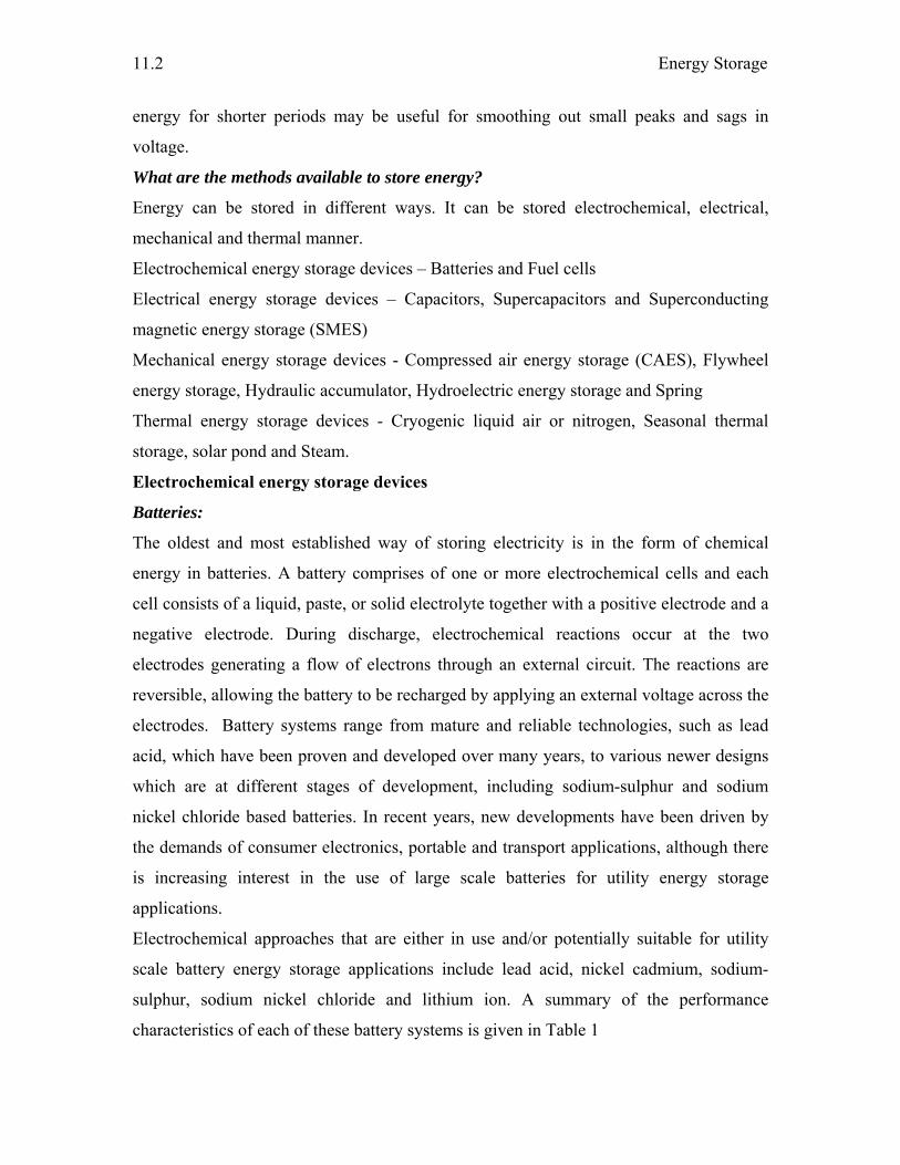
Energy Storage
11.2
energy for shorter periods may be useful for smoothing out small peaks and sags in
voltage.
What are the methods available to store energy?
Energy can be stored in different ways. It can be stored electrochemical, electrical,
mechanical and thermal manner.
Electrochemical energy storage devices – Batteries and Fuel cells
Electrical energy storage devices – Capacitors, Supercapacitors and Superconducting
magnetic energy storage (SMES)
Mechanical energy storage devices - Compressed air energy storage (CAES), Flywheel
energy storage, Hydraulic accumulator, Hydroelectric energy storage and Spring
Thermal energy storage devices - Cryogenic liquid air or nitrogen, Seasonal thermal
storage, solar pond and Steam.
Electrochemical energy storage devices
Batteries:
The oldest and most established way of storing electricity is in the form of chemical
energy in batteries. A battery comprises of one or more electrochemical cells and each
cell consists of a liquid, paste, or solid electrolyte together with a positive electrode and a
negative electrode. During discharge, electrochemical reactions occur at the two
electrodes generating a flow of electrons through an external circuit. The reactions are
reversible, allowing the battery to be recharged by applying an external voltage across the
electrodes. Battery systems range from mature and reliable technologies, such as lead
acid, which have been proven and developed over many years, to various newer designs
which are at different stages of development, including sodium-sulphur and sodium
nickel chloride based batteries. In recent years, new developments have been driven by
the demands of consumer electronics, portable and transport applications, although there
is increasing interest in the use of large scale batteries for utility energy storage
applications.
Electrochemical approaches that are either in use and/or potentially suitable for utility
scale battery energy storage applications include lead acid, nickel cadmium, sodium-
sulphur, sodium nickel chloride and lithium ion. A summary of the performance
characteristics of each of these battery systems is given in Table 1
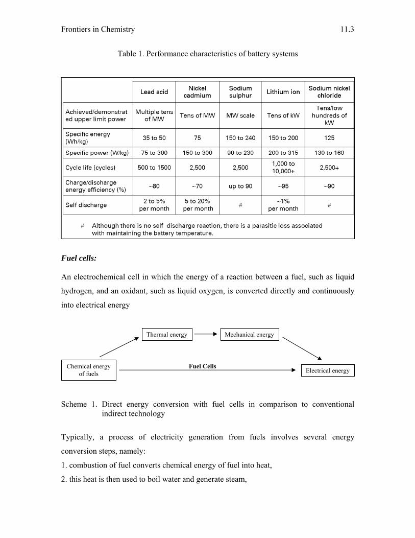
Frontiers in Chemistry
11.3
Table 1. Performance characteristics of battery systems
Fuel cells: An electrochemical cell in which the energy of a reaction between a fuel, such as liquid
hydrogen, and an oxidant, such as liquid oxygen, is converted directly and continuously
into electrical energy
Scheme 1. Direct energy conversion with fuel cells in comparison to conventional indirect technology
Typically, a process of electricity generation from fuels involves several energy
conversion steps, namely:
1. combustion of fuel converts chemical energy of fuel into heat,
2. this heat is then used to boil water and generate steam,
Chemical energy of fuels
Thermal energy Mechanical energy
Electrical energy Fuel Cells
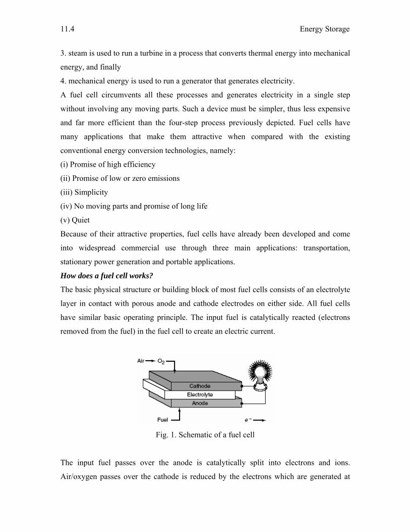
Energy Storage
11.4
3. steam is used to run a turbine in a process that converts thermal energy into mechanical
energy, and finally
4. mechanical energy is used to run a generator that generates electricity.
A fuel cell circumvents all these processes and generates electricity in a single step
without involving any moving parts. Such a device must be simpler, thus less expensive
and far more efficient than the four-step process previously depicted. Fuel cells have
many applications that make them attractive when compared with the existing
conventional energy conversion technologies, namely:
(i) Promise of high efficiency
(ii) Promise of low or zero emissions
(iii) Simplicity
(iv) No moving parts and promise of long life
(v) Quiet
Because of their attractive properties, fuel cells have already been developed and come
into widespread commercial use through three main applications: transportation,
stationary power generation and portable applications.
How does a fuel cell works?
The basic physical structure or building block of most fuel cells consists of an electrolyte
layer in contact with porous anode and cathode electrodes on either side. All fuel cells
have similar basic operating principle. The input fuel is catalytically reacted (electrons
removed from the fuel) in the fuel cell to create an electric current.
Fig. 1. Schematic of a fuel cell
The input fuel passes over the anode is catalytically split into electrons and ions.
Air/oxygen passes over the cathode is reduced by the electrons which are generated at
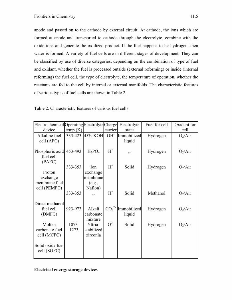
Frontiers in Chemistry
11.5
anode and passed on to the cathode by external circuit. At cathode, the ions which are
formed at anode and transported to cathode through the electrolyte, combine with the
oxide ions and generate the oxidized product. If the fuel happens to be hydrogen, then
water is formed. A variety of fuel cells are in different stages of development. They can
be classified by use of diverse categories, depending on the combination of type of fuel
and oxidant, whether the fuel is processed outside (external reforming) or inside (internal
reforming) the fuel cell, the type of electrolyte, the temperature of operation, whether the
reactants are fed to the cell by internal or external manifolds. The characteristic features
of various types of fuel cells are shown in Table 2.
Table 2. Characteristic features of various fuel cells
Electrochemical device
Operating temp (K)
ElectrolyteCharge carrier
Electrolyte state
Fuel for cell Oxidant for cell
Alkaline fuel cell (AFC)
Phosphoric acid
fuel cell (PAFC)
Proton
exchange membrane fuel cell (PEMFC)
Direct methanol fuel cell (DMFC)
Molten
carbonate fuel cell (MCFC)
Solid oxide fuel
cell (SOFC)
333-423
453-493
333-353
333-353
923-973
1073-1273
45% KOH
H3PO4
Ion exchange membrane
(e.g., Nafion)
,,
Alkali carbonate mixture Yttria-
stabilized zirconia
OH-
H+
H+
H+
CO32-
O2-
Immobilized liquid
,,
Solid
Solid
Immobilized liquid
Solid
Hydrogen
Hydrogen
Hydrogen
Methanol
Hydrogen
Hydrogen
O2/Air
O2/Air
O2/Air
O2/Air
O2/Air
O2/Air
Electrical energy storage devices
Energy Storage
11.6
Capacitors and supercapacitors:
Capacitors store energy in an electrostatic field rather than as a chemical state as in
batteries. No chemical reactions involved which means very long cycle life is possible.
No limit on the cell voltage imposed by the "cell chemistry" as with galvanic cells. The
terminal voltage is directly proportional to the State of Charge (SOC) which limits range
of applicability somewhat.
Capacitors consist of two conductive parallel plates and separated by a dielectric
insulator. The plates hold opposite charges which generate an electric field. Unlike in
batteries where energy is stored in chemical form, capacitors store energy in the form of
field.
The capacitance is defined as C = (A/d) εrε0
where A is the area of the parallel plates d is the distance between them, εr is the relative
permittivity or dielectric constant and εo is the permittivity of free space (8.854 x 10⁻¹²
F/m).
The energy stored by the capacitor is given by E = (½) C V 2
The energy density of supercapacitors can be four times more compared to the normal
capacitor. The basic principle of energy storage in a supercapacitor is based on creating a
charge-separated state in an electrochemical double layer. In this case, energy storage is
based on the separation of charges in the double layer across the electrode/electrolyte
interface. The positive electrode is electron deficient whereas the negative electrode
contains a surplus of electrons. The energy (W) stored in a capacitor as a function of the
voltage applied (U) and the capacity (C) is given by the equation : W = CU2/2.
Compared to conventional capacitors where a total capacitance of pF and mF is typical,
the capacitance of and the energy density stored in the electrochemical double layer are
high. In order to achieve a higher capacitance the electrode surface area is additionally
increased by using porous electrodes with an extremely large internal effective surface.
Combination of two such electrodes gives an electrochemical capacitor of rather high
capacitance.
Electrochemical capacitors are used as back-up memory for electronic devices
like VCR circuits, CD players, cameras, computers, clocks, clock radios, telephones and
other electronic equipments. Electrochemical capacitors also used in hybrid electric
Frontiers in Chemistry
11.7
vehicles in combination with batteries as their power density is higher than batteries for
load leveling. Electrochemical capacitors in combination with batteries occupy less space
and are light, have excellent cold weather starting and increased battery life. Other uses
of electrochemical capacitors include regenerative breaking, unmanned monitoring units,
uninterruptible power supplies (UPS), and high power lasers.
The supercapacitor has become available to the public. A commercial
supercapacitor can hold 2500 farads, release 300 A of peak current with a peak voltage
handling of about 400 V. The life-cycle of this supercapacitor is more than 1x10⁶
charge/recharge cycles.
Superconducting magnetic energy storage (SMES)
Superconducting magnetic energy storage (SMES) system is a device for storing and
instantaneously discharging large quantities of power. It stores energy in the magnetic
field created by the flow of DC in a coil of superconducting material that has been
cryogenically cooled. These systems have been in use for several years to improve
industrial power quality and to provide a premium-quality service for individual
customers vulnerable to voltage fluctuations. The SMES recharges within minutes and
can repeat the charge/discharge sequence thousands of times without any degradation of
the magnet. Recharge time can be accelerated to meet specific requirements, depending
on system capacity.
As an energy storage device, SMES is a relatively simple concept. It stores electric
energy in the magnetic field generated by DC current flowing through a coiled wire. If
the coil were wound using a conventional wire such as copper, the magnetic energy
would be dissipated as heat due to the wire's resistance to the flow of current. However, if
the wire is superconducting (no resistance), then energy can be stored in a “persistent''
mode, virtually indefinitely, until required. Superconductors have zero resistance to DC
electrical current at low temperatures so that ohmic heat dissipation is eliminated; hence
the refrigerator is needed in the SMES to cool the coil.
The energy stored within the coil is given by E = ½ LI2
where L is the inductance of the coil, and I is the current passing through it. The
volumetric energy density is given by UD = B2/2μo
Energy Storage
11.8
SMES systems are environmentally friendly because superconductivity does not produce
a chemical reaction. In addition, there are no toxins produced in the process. SMES can
be used in enhancing transmission line capacity and performance. In a SMES system,
energy is stored within a magnet that is capable of releasing megawatts of power within a
fraction of cycle to replace a sudden loss in line power. The SMES recharges within
minutes and can repeat the charge and discharge sequence thousands of times without
any degradation of the magnet. Some SMES systems are designed to improve the power
quality for critical loads and to provide carryover energy during voltage sags and
momentary power outages. The system stores energy in a Superconducting coil immersed
in liquid helium. It helps out overcome problems like sags, spikes, and voltage and
frequency instabilities.
Mechanical energy storage devices
Compressed air energy storage (CAES):
In compressed air energy storage, off-peak power is taken from the grid and is used to
pump air into a sealed underground cavern to a high pressure. The pressurized air is then
kept underground for peak use. When needed, this high pressure can drive turbines as the
air in the cavern is slowly heated and released; the resulting power produced may be used
at peak hours. More often, the compressed air is mixed with natural gas and they are
burnt together, in the same fashion as in a conventional turbine plant. This method is
actually more efficient as the compressed air will lose less energy.
A CAES operates by means of large electric motor driven compressors that store
energy in the form of compressed air in the mine. The compression is done outside
periods of peak demand. As part of the compression process, the air is cooled prior to
injection to make the best possible use of the storage space available. The air is then
pressurized to about 75 bar. To return electricity to the customers, air is extracted from
the cavern. It is first preheated in the recuperator. The recuperator reuses the energy
extracted by the compressor coolers. The heated air is then mixed with small quantities of
oil or gas, which is burnt in the combustor. The hot gas from the combustor is expanded
in the turbine to generate electricity
Frontiers in Chemistry
11.9
CAES systems can be used on very large scales. Unlike other systems considered large-
scale, CAES is ready to be used with entire power plants. Apart from the hydro-pump, no
other storage method has a storage capacity as high as CAES. Typical capacities for a
CAES system are around 50-300 MW. The storage period is also the longest due to the
fact that its losses are very small. A CAES system can be used to store energy for more
than a year. Fast start-up is also an advantage of CAES. A CAES plant can provide a
start-up time of about 9 minutes for an emergency start, and about 12 minutes under
normal conditions. By comparison, conventional combustion turbine peaking plants
typically require 20 to 30 minutes for a normal start-up. If a natural geological formation
is used (rather than CAS), CAES has the advantage that it doesn't involved huge, costly
installations. Moreover, the emission of green house gases is substantially lower than in
normal gas plants.
The main drawback of CAES is probably the geological structure reliance. There is
actually not a lot of underground cavern around, which substantially limits the usability
of this storage method. However, for locations where it is suitable, it can provide a viable
option for storing energy in large quantities and for long times.
Flywheel energy storage
Kinetic energy storage systems operate on the basis of stored energy in a rotating mass
which is converted from and to electrical energy via a motor/generator set. Such kinetic
energy storage systems (or flywheel storage systems, as they are more commonly known)
tend to fall into two discrete categories, namely conventional steel rotor systems or
advanced composite machines. Flywheels have been used in steam boats and wind mills
in the past as a method of transferring energy.
A flywheel is basically a spinning disc with a hole in the middle to be used for
rotation. The technological developments, from the birth of the first flywheel for storing
energy to the zero idling loss High critical Temperature Superconductor bearings (HTS)
flywheel will be explored. Although there are some significant differences between the
many types of flywheels, the idea behind them is simple. The applications of these
flywheels will be explored, especially commercial applications.
The main applications of flywheels are to supply components and machines with
high output voltages when there is a power surge or a shutdown. However, some
Energy Storage
11.10
companies are researching the use of flywheels in different fields. An example is the
application of flywheels in starting and braking locomotives. Previously, chemical means
of storing energy were used, but this involved heavy and bulky equipment. A flywheel is
very practical for its light weight and high energy capacity. The energy is restored back
into the flywheel using traction motors when the train moves down a slope. Flywheels
have been introduced in the market of electric vehicles. A large amount of energy is
needed to start an electric engine. Previously, cars used a chemical battery but it was not
economical as it had a limited amount of charge/discharge cycle. The flywheel can be
charged/discharged as many times as needed. Again, as with the locomotive, energy
losses during braking can be minimized by storing excess energy and releasing it when
accelerating.
Hydraulic accumulator:
Hydraulic accumulator is a pressure storage reservoir in which a non compressible
hydraulic fluid is retained under pressure from an external source. Its main function is to
store hydraulic energy and is necessary to make the energy available again to the system.
A hydraulic accumulator is also referred to as the capacitance of the system.
The different types of accumulators include
(A) Dead weight type: The dead weight accumulator consists of a piston loaded with a
dead weight and moving within a cylinder that exerts pressure on the hydraulic oil. The
dead weight may be of some heavy material such as iron, concrete block, and scrap iron.
(B) Spring loaded type: Whether single-spring or multiple-spring type, the springs in this
accumulator, act against a hydraulic piston forcing the fluid into the hydraulic system. A
spring loaded accumulator consists of a cylinder body, a movable piston and a spring.
The spring applies force to the piston. As fluid is pumped to it, the pressure in the
accumulator is determined by the compression rate of the spring.
(C) Hydro-pneumatic type: The hydro-pneumatic accumulators are the most commonly
used accumulators and apply force to the liquid by using a compressed gas that acts as the
spring. It uses only dry nitrogen as there is a danger of exploding an air-oil vapor, in the
case of compressed air. The different types of hydro-pneumatic accumulators used are:
1. Non-separator type, but not used due to possibility of foaming: It consists of a cylinder
with hydraulic fluid and the charging gas with no separation between them. They are
Frontiers in Chemistry
11.11
generally used on die casting machines or other similar places. They are always to be
mounted vertically.
2. Piston: It consists of a cylinder body and a movable piston. The gas that occupies the
volume above the piston is compressed as the cylinder body is charged with liquid.
3. Diaphragm: It consists of two metal hemispheres which are separated by flexible,
synthetic rubber diaphragm. The storing action is effected by the compression of the
volume of nitrogen enclosed in the diaphragm.
4. Bladder: It consists of a synthetic polymer rubber bladder like chloroprene, nitrile, etc.
inside a metal (steel) shell. The bladder is filled with compressed gas. It responds quickly
for receiving or expelling flow of oil. There is always a possibility of bladder failure that
needs to be taken into consideration.
The hydraulic accumulators are applicable for hydraulic shock suppression is
suitable for leakage compensation. The accumulators are the source of power during
power failures. They aptly hold high pressure for long periods without keeping the pump
running. They have wide applicability in large hydraulic presses, diesel engine starters,
hydraulically operated hospital beds, farm machinery, landing gear mechanism on
airplanes, hatch cover in ships, lifts, trucks, etc.
Hydroelectric energy storage:
Pumped storage hydroelectricity is a method of storing and producing electricity to
supply high peak demands by moving water between reservoirs at different elevations.
Pumped hydroelectric energy storage has been in use since 1929, making it the oldest
kind of large-scale energy storage technology. In fact, until 1970, it was the only
commercially available option for storing energy. Pumped hydroelectric stations are in
active operation and new ones are still being built. Time has proven it to be an effective
method for storing large amounts of energy. A pumped hydroelectic storage system
consists of two large reservoirs located at different elevations. During peak demand,
water is released from the upper reservoir. It drops downward through high-pressure
shafts where it passes through turbines and ultimately pools up in the lower reservoir.
The turbines drive power generators that create electricity. Therefore, when releasing
energy during peak demand, a pumped hydroelectric storage system works similarly to
Energy Storage
11.12
traditional hydroelectricity. When production exceeds demand, water is pumped up and
stored in the upper reservoir, ready to be released as needed.
Out of all large-scale energy storage methods, pumped hydroelectric storage is the
most effective. It can store the largest capacity of electricity (over 2000 MW) and the
period of storage is also among the longest; a typical plant can store its energy for more
than half a year. Due to the rapid response speed, pumped hydroelectic storage systems
are particularly useful as backup in case of sudden changes in demand. Partly due to the
large scale and the relative simplicity of design, the operating cost per unit of energy is
among the cheapest; the cost of storing energy can be an order of magnitude lower in
pumped hydroelectic systems than in for example superconducting magnetic storage
systems. Unlike hydroelectric dams, a pumped hydroelectic system has little effect on the
landscape. It produces no pollution or waste.
However, the pumped hydroelectic storage system has its drawbacks too.
Probably the most fundamental one is its dependence on specific geological formations.
There have to be two large volume reservoirs along with sufficient amount of head for
the building to be feasible. This is uncommon and often forces the location of the plants
to be in remote places, like in the mountains, where construction is difficult and the
power grid is not present. Although its operating cost is cheap, the capital cost of a
pumped hydroelectric plant is massive, as it often involves building dams and enormous
underground pipes. In terms of environmental issues, it disturbs the local habitat as the
water level fluctuates daily. Also, the full amount of water has to be pumped up or down
in one go, that is, the system must be `drained' completely before recharging, although
elaborate planning could get around this.
Thermal energy storage devices
Cryogenic liquid air or nitrogen:
A liquid nitrogen economy is a hypothetical proposal for a future economy in which the
primary form of energy storage and transport is liquid nitrogen. It is proposed as an
alternative to liquid hydrogen in some transport modes and as a means of locally storing
energy captured from renewable sources. An analysis of this concept provides insight
into the physical limits of all energy conversion schemes.
Seasonal thermal storage:

Frontiers in Chemistry
11.13
A seasonal thermal store (also known as a seasonal heat store or inter-seasonal thermal
store) is a store designed to retain heat deposited during the hot summer months for use
during colder winter weather. The heat is typically captured using solar collectors,
although other energy sources are sometime used separately or in parallel. Seasonal
thermal storage can be divided into two broad categories: Low-temperature systems use
the soil adjoining the building as a low-temperature seasonal heat store (reaching
temperatures similar to average annual air temperature), drawing upon the stored heat for
space heating. Such systems can also be seen as an extension to the building design
(normally passive solar building design), as the design involves some simple but
significant differences when compared to 'traditional' buildings. High-temperature
seasonal heat stores are essentially an extension of the building's high voltage alternating
current and water heating systems. Water is normally the storage medium, stored in tanks
at temperatures that can approach boiling point. Phase change materials (which are
expensive but which require smaller tanks) and high-tech soil heating systems (remote
from the building) are occasionally used instead. For systems installed in individual
buildings, additional space is required to accommodate the size of the storage tanks. In
both cases, effective above-ground insulation / superinsulation of the building structure is
required to minimise heat-loss from the building, and hence the amount of heat that needs
to be stored and used for space heating.
Solar pond
A solar pond is large-scale solar energy collector with integral heat storage for supplying
thermal energy. A solar pond can be used for various applications, such as process eating,
water desalination, refrigeration, drying and solar power generation. The solar pond
works on a very simple principle. It is well-known that water or air is heated they become
lighter and rise upward e.g. a hot air balloon. Similarly, in an ordinary pond, the sun’s
rays heat the water and the heated water from within the pond rises and reaches the top
but loses the heat into the atmosphere. The net result is that the pond water remains at the
atmospheric temperature. The solar pond restricts this tendency by dissolving salt in the
bottom layer of the pond making it too heavy to rise.
A solar pond has three zones. The top zone is the surface zone, or UCZ (Upper
Convective Zone), which is at atmospheric temperature and has little salt content. The
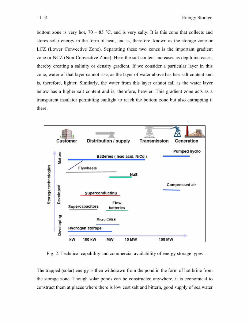
Energy Storage
11.14
bottom zone is very hot, 70 – 85 °C, and is very salty. It is this zone that collects and
stores solar energy in the form of heat, and is, therefore, known as the storage zone or
LCZ (Lower Convective Zone). Separating these two zones is the important gradient
zone or NCZ (Non-Convective Zone). Here the salt content increases as depth increases,
thereby creating a salinity or density gradient. If we consider a particular layer in this
zone, water of that layer cannot rise, as the layer of water above has less salt content and
is, therefore, lighter. Similarly, the water from this layer cannot fall as the water layer
below has a higher salt content and is, therefore, heavier. This gradient zone acts as a
transparent insulator permitting sunlight to reach the bottom zone but also entrapping it
there.
Fig. 2. Technical capability and commercial availability of energy storage types
The trapped (solar) energy is then withdrawn from the pond in the form of hot brine from
the storage zone. Though solar ponds can be constructed anywhere, it is economical to
construct them at places where there is low cost salt and bittern, good supply of sea water

Frontiers in Chemistry
11.15
or water for filling and flushing, high solar radiation, and availability of land at low cost.
The technical capability and commercial availability of several types of storage are
shown in Figure 2.
References:
1. R.M. Dell and D.A.J. Rand, Journal of Power Sources, 100 (2001) 2
2. M. Winter and Ralph J. Brodd, Chem. Rev., 104 (2004) 4245
3. R. Narayanan and B.Viswanathan (Eds.), Chemical and electrochemical energy
systems. Universities Press (India) Limited, 1998.
4. B. viswanathan amd M. Aulice scibioh, Fuel cells: principles and applications,
Universities Press (India) Limited, 2006
5. R. Kotz and M. Carlen, Electrochimica Acta, 45 (2000) 2483
6. G. Ries and H.-W. Neumueller, Physica C 357–360 (2001) 1306
7. Haichang Liu and Jihai Jiang, Energy and Buildings, 39 (2007) 599
8. I. Dincer and M.A. Rosen, Thermal Energy Storage: Systems and Applications, John
Wiley and Sons, New York, USA, 2003
9. http://www.sandia.gov/ess/index.html
10. http://www.energystoragecouncil.org

Chapter - 12 DIAGNOSIS AND DRUG DELIVERY
J. Rajeswari
1. Introduction
Accurate and early diagnosis as well as the effective treatment without side effects is the
two prime factors on which the success of medicine depends on. Today, accurate
diagnosis is made simple by the introduction of simple devices called as ‘Lab on a Chip’.
The limitations with chip technologies are incapability to detect low abundant targets.
Increasing the signals at low abundance will be a good option to overcome this. This has
been shown to overcome using bioconjugated nanoparticles on these chips. At present,
‘Lab on a Chip’ can be defined as devices or systems constructed using techniques
inspired from nano-scale fabrication and the application of these chips range from
diagnostics to drug delivery.
The development of new multidisciplinary branch, “Nanomedicine”, discovery of
miniaturized devices and sensors have revolutionized the field of medicine and human
health. Nanomedicine includes biology, chemistry, physics, engineering and materials
science. Nanomedicine may be defined as the monitoring, repair, construction and
control of human biological systems at the molecular level, using engineered nanodevices
and nanostructures. There are several reasons for attempting materials and devices in
nanoscale for medicinal applications. The promise that nanotechnology brings is
multifaceted, offering not only improvements to current techniques but also providing
entirely new tools and capabilities. By manipulating drugs and other materials at the
nanometer scale, the fundamental properties and bioactivity of materials can be altered.
These tools can permit control over characteristics of drugs or agents such as solubility,
blood pool retention times, controlled release over short or long durations,
environmentally triggered controlled release or highly specific site-targeted delivery.
Furthermore, by using nanometer-sized particles, the increased functional surface area
per unit volume can be exploited in various ways.
Integration of nanotechnology into complex biological systems leads to detection
and prevention of disease at the earliest stages of its development. Nanotechnology

Diagnosis and Drug Delivery
12.2
appears to bring a breakthrough in the field of medicine. They seem to be a suitable
choice for the present day’s need in medicine and biology. Their application to this field
range widely from diagnosis, therapeutic applications, surgery and artificial implants.
The unique optical, magnetic and electronic properties of nanomaterials enable them to
be promising materials in all fields of medicine. Many biocatalysts such as enzymes or
catalytic antibodies are available for performing a variety of synthetically important
transformations or for bio-sensing applications. Glucose oxidase (GOD) is by far the
most studied enzyme which catalyzes the oxidation of glucose by molecular oxygen and
finds many applications in clinical analysis for the diagnosis of diabetes and in the food
industry. Optical bio-sensors or amperometric biosensors have been extensively used in
biosensors for the titration of glucose. A new kind of hybrid biosensor based on changes
in enthalpy during the enzymatic oxidation of glucose recorded as a thermometric peak
by a sensitive thermistor has been recently described in order to detect glucose in fruit
juice, Coca Cola and human blood serum. Diseases can be linked to specific changes in
the molecular processes of affected cells and tissues. When the cells are affected during
disease, changes in the protein can be observed. Hence, there can be molecular
signatures of disease. This helps in early detection and diseases. These signatures are
sensitive to any one of the techniques such as fluorescence and magnetic field or can be
detected using devices such as DNA and protein chips. All these emerging technologies
and materials have led new strategies to monitor and maintain the health. In this chapter,
we will discuss the current achievements in the field of nanomedicine for diagnosis and
drug delivery.
2. Nanotechnology for medical diagnostics
There are several reports and ongoing research on the use of nanotechnology for early
detection of several diseases. It has been proved that nanoparticles show a very high
sensitivity towards the detection of target biomolecules even when they are present at a
very low concentrations. Nanoparticles or nanotechnology based devices have been
shown to be promising than the conventional materials or techniques in several aspects
such as signal amplification, sensitivity, specificity and easy handling. Functionalized
nanoparticles when conjugated with biomolecules have shown the ability to detect
antibodies, proteins and damaged or disease cells by various methods. Few techniques
Frontiers in Chemistry
12.3
based on nanoparticles or nanotechnology for diagnosis are discussed below.
Nanoparticles possessing unique optical, electronic and magnetic properties have been
demonstrated by several researchers as possible probes to detect biological species. Not
only the minute size of nanocrystals comparable to biologically functional molecules, but
also the ability to tune their biochemical properties by modifying their size, shape, and
composition make these materials useful and optimized for the bio-medical purposes.
Nanotechnology has the potential to bring dramatic improvement in the field of bio-
medical sciences including detection, diagnosis, and therapeutic systems.
2. 1. Electrochemical biosensors
Biosensors are small devices employing biochemical molecular recognition properties as
the basis for a selective analysis. The major processes involved in any biosensor system
are analyte recognition, signal transduction, and readout. Due to their specificity, speed,
portability, and low cost, biosensors offer exciting opportunities for numerous
decentralized clinical applications, ranging from ‘alternative-site’ testing (e.g.,
physician’s office), emergency-room screening, bedside monitoring, or home self testing.
Such devices produce a simple, inexpensive and yet accurate and sensitive platform for
patient diagnosis. The name electrochemical biosensor is applied to a molecular sensing
device which intimately couples a biological recognition element to an electrode
transducer. The purpose of the transducer is to convert the biological recognition event
into a useful electrical signal. They use biological molecules, usually enzyme, antibody,
or nucleic acid to recognize sample molecules of interest via hydrogen bonding, charge–
charge interactions and other biochemical interactions to provide molecular information.
The integration of biological systems and nanostructured materials requires information
to be induced across the interface in a consistent and reproducible format. Recent
advances in the field of nanotechnology and processing have resulted in solid-state
biosensors offering unprecedented compatibility of inorganic materials with the
chemical/biological agents, thus enabling stable, direct, and reproducible screening and
detection. Amperometric and potentiometric transducers are most commonly used in
conjunction with electrochemical biosensors. In potentiometric devices, the analytical
information is obtained by converting the bio recognition process into a potential signal
in connection to the use of ion selective electrodes (ISE). Amperometric biosensors
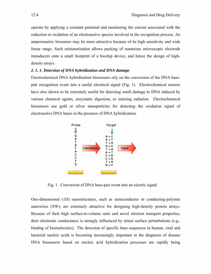
Diagnosis and Drug Delivery
12.4
operate by applying a constant potential and monitoring the current associated with the
reduction or oxidation of an electroactive species involved in the recognition process. An
amperometric biosensor may be more attractive because of its high sensitivity and wide
linear range. Such miniaturization allows packing of numerous microscopic electrode
transducers onto a small footprint of a biochip device, and hence the design of high-
density arrays.
2. 1. 1. Detection of DNA hybridization and DNA damage
Electrochemical DNA hybridization biosensors rely on the conversion of the DNA base-
pair recognition event into a useful electrical signal (Fig. 1). Electrochemical sensors
have also shown to be extremely useful for detecting small damage to DNA induced by
various chemical agents, enzymatic digestion, or ionizing radiation. Electrochemical
biosensors use gold or silver nanoparticles for detecting the oxidation signal of
electroactive DNA bases in the presence of DNA hybridization.
Fig. 1. Conversion of DNA base-pair event into an electric signal
One-dimensional (1D) nanostructures, such as semiconductor or conducting-polymer
nanowires (NW), are extremely attractive for designing high-density protein arrays.
Because of their high surface-to-volume ratio and novel electron transport properties,
their electronic conductance is strongly influenced by minor surface perturbations (e.g.,
binding of biomolecules), The detection of specific base sequences in human, viral and
bacterial nucleic acids is becoming increasingly important in the diagnosis of disease
DNA biosensors based on nucleic acid hybridization processes are rapidly being
Frontiers in Chemistry
12.5
developed towards the goal of rapid and inexpensive diagnosis of genetic and infectious
diseases. an electrochemical biosensor for the voltammetric detection of DNA sequences
related to the Hepatitis B virus (HBV) and TT virus (TTV) from polymerase chain
reaction (PCR) amplified real samples has been reported.
2. 2. Fluorescent NP for biosensors and Biolabelling
Nanoparticles exhibit remarkable optical and electronic properties when compared to
their bulk counterpart. Hence, they are found to be an excellent fluorescent probes for
imaging, signaling, evolution and targeting of cells. This method of diagnosis relies on
nanoparticles which have the capability of emitting color during absorption of light. The
nanoparticles should be able to distinguish the presence and absence of biomolecules by
producing characteristic color. This way they can function as labels or sensors for
biomolecules. Fluorescent markers for diagnostic purposes exist in the markets from a
long time but there are limitations associated with them. To overcome, fluorescent
nanoparticles are being developed. Multi-color labeling of both fixed and living cells
with fluorescent nanoparticles conjugated with biological ligands that specifically bind
against certain cellular targets enables the recording of diffusion pathways in receptor
cells. Uptake of nanoparticles into the vesicular compartments around the nucleus of cells
can be used to label the cells so that their pathway and fate can be followed. The
nanoparticles exhibit reduced photobleaching as compared to traditional dyes and are
passed on to daughter cells during cell division, therefore allowing for much longer term
observation. Colloidal gold nanoparticles have been found to strongly enhance the native
signals of chemical constituents in cells. Surface Enhanced Raman Spectroscopy (SERS)
relies on this signal magnification and serves as a tool for ultra-sensitive monitoring of
the intracellular distribution of these chemicals. Colloidal gold biofunctionalized
nanomodules also have potential for use in enzyme multi-sensors. Gold nanoparticles
coated with proteins have been used to detect conformation changes in the attached
proteins via observation of color changes in the solution.
2. 2. 1. Quantum Dots (QDs)
Quantum Dots (QDs) are one of the possible fluorescent nanoparticles for diagnostic
applications. QDs are crystalline clumps of a few hundred atoms, coated with an
insulating outer shell of a different material. They are spherical nanocrystals in 1-10 nm
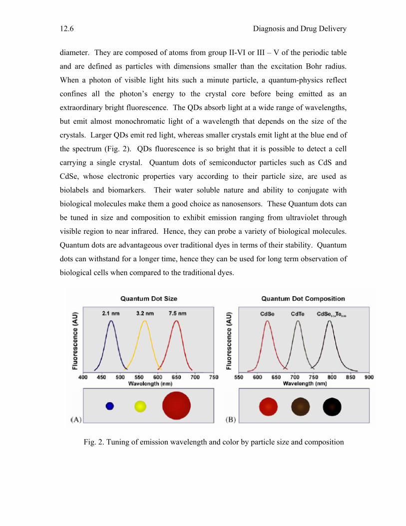
Diagnosis and Drug Delivery
12.6
diameter. They are composed of atoms from group II-VI or III – V of the periodic table
and are defined as particles with dimensions smaller than the excitation Bohr radius.
When a photon of visible light hits such a minute particle, a quantum-physics reflect
confines all the photon’s energy to the crystal core before being emitted as an
extraordinary bright fluorescence. The QDs absorb light at a wide range of wavelengths,
but emit almost monochromatic light of a wavelength that depends on the size of the
crystals. Larger QDs emit red light, whereas smaller crystals emit light at the blue end of
the spectrum (Fig. 2). QDs fluorescence is so bright that it is possible to detect a cell
carrying a single crystal. Quantum dots of semiconductor particles such as CdS and
CdSe, whose electronic properties vary according to their particle size, are used as
biolabels and biomarkers. Their water soluble nature and ability to conjugate with
biological molecules make them a good choice as nanosensors. These Quantum dots can
be tuned in size and composition to exhibit emission ranging from ultraviolet through
visible region to near infrared. Hence, they can probe a variety of biological molecules.
Quantum dots are advantageous over traditional dyes in terms of their stability. Quantum
dots can withstand for a longer time, hence they can be used for long term observation of
biological cells when compared to the traditional dyes.
Fig. 2. Tuning of emission wavelength and color by particle size and composition
Frontiers in Chemistry
12.7
Several properties of quantum dots (QDs) make them suitable choice as fluorescent labels
for biomolecules when compared to organic dyes.
(i) QDs exhibit narrow and symmetric emission peaks (FWHM typically 25-35
nm) whereas organic dyes show broad and unsymmetric emission peaks.
Hence, QDs are suitable materials when simultaneous labeling and detection
of multiple analytes are desired.
(ii) QDs have large molar absorptivities and high quantum yield
(iii) Quantum dots can withstand for a longer time, hence they can be used for long
term observation of biological cells when compared to the traditional dyes. The rate
of photodegradation is low for QDs.
Other than QDs, there is another type of fluorescent labels, wherein traditional
luminescent dye tris(2,2-bipyridyl) dichlororuthenium (II) hexahydrate (Rubpy) is
encapsulated into silica nanoparticles. By doing so, significant signal amplification has
been observed as the high surface area silica nanoparticles can take in large number of
luminescent dye inside its matrix. In addition to their high surface to volume ratio, dye
silica nanoparticles have other advantages such as high intensity of fluorescent signal,
excellent photostability due to exclusion of oxygen by silica encapsulation, efficient
conjugation with biomolecules due to the easy modification of silica surface and also
easy manufacturing process. Biomolecules such as streptavidin and avidin are
conjugated to the silica surfaces of the nanoparticles. These systems were used in the area
of imunocytochemistry where IgM – bearing cell surfaces are labeled using NPs. They
exhibit red fluorescence. Dye doped silica nanoparticles have also been used in DNA
microarrays which are used in genomics, drug discovery and clinical diagnosis. The
common problem in such DNA microarrays is the difficulty in diagnosing low abundant
targets. This has been overcome using nanoparticles modified DNA microarrays.
Nanoparticles conjugated DNA microarrays showed intense fluorescence signals than the
DNA microarrays without nanoparticles. Nanoparticles have also been shown to
determine the DNA quantitatively as the fluorescence signals reflected the amount of
DNA on the array. Protein microarrays have been used in protein expression, protein
Diagnosis and Drug Delivery
12.8
profiling and protein – protein interactions among others. Avidin nanoparticles showed
specificity to the hIgG – biotin was spotted. These results show that the bioconjugated
nanoparticles exhibit siginificant amplification of the analytical signal compared to the
traditional dye as the amount of dye molecules are more in the nanoparticles than the
conventional immunoassays. The nanoparticles can generate specific and high intensity
fluorescent signals according to the antibody – antigen interaction, thus making it
possible to detect bacterial or viral pathogens. The ultimate power of the fluorescent
nanoparticles will emerge as a revolutionary tool for ultrasensitive detection of disease
markers and infectious agents.
Some class of organophosphorous (OP) neurotoxins is extremely toxic to
mammals and also they form chemical warfare agents. They are powerful inhibitors of
esterase enzymes, such as acetyl and butyryl- cholinesterases or neurotoxic esterase
which are involved in neurotoxins. Sensitive biosensors based on acetylcholinesterase
(AChE) or butyryl cholinesterase (BChE) inhibition have been developed and used for
OP agent detection. In inhibition based biosensors, the organophosphorus inhibits the
active site of enzyme resulting in loss of enzyme activity and hence a decrease in sensor
signal. There are several disadvantages. (1) any environmental or handling factors that
cause loss of enzyme activity will result in false positive signals, (2) such sensors require
baseline testing prior to sample application and lengthy sample incubation times to allow
enzyme-analyte interaction (3) due to the irreversible nature of cholinesterase enzyme
inhibition, inhibition-based sensors cannot be reused without regeneration of enzyme
activity. A method based on gold nanoparticles has been developed to detect the presence
of OP compound.
2. 3. Magnetic Nanoparticles
Magnetic nanoparticles are the other class of materials which find applications in
frontiers of materials science including medical diagnosis. In addition to their high
surface to volume ratio and quantum size effect, magnetic nanoparticles dramatically
change some of the magnetic properties and exhibit superparamagnetic phenomena and
quantum tunneling of magnetization, because each particles can be considered as a single
magnetic domain. When bound to a suitable antibody, they are used to label specific
molecules, cell populations, structures or microorganisms. Magnetic nanoparticles have
Frontiers in Chemistry
12.9
been extensively studied for biomedical applications such as hyperthermia, magnetic
resonance contrast enhancement and drug delivery. The magnetic field produced by the
magnetic target molecules when conjugated to the antibody is measured as the signal and
hence detected. The medical MRI (magnetic resonance imaging) relies on the relaxation
properties of hydrogen nuclei in water and lipids. For MRI, iron oxide based
nanoparticles and its related systems have been widely used. They consist of an
inorganic core of iron oxide (magnetite Fe2O3, maghemite or other insoluble ferrites)
coated with polymer such as dextran. Lumiren (silicon-coated iron oxide particles with
diameter 300 nm) and Endorem (magnetite nanoparticles of 150 nm in diameter coated
with dextran) are commercial names of Superparamagnetic nanoparticles.
Superconducting quantum interference device (SQUID) is a technique for
specific, sensitive, quantitative and rapid detection of biological targets by using
supermagnetic nanoparticles and a microscope based on a high transition temperature. In
this technique, a mylar film to which the targets are bound is placed on the microscope
alongside SQUID. A suspension of magnetic nanoparticles carrying antibodies directed
against the target is added to the mixture in the well and 1-s pulse of magnetic field is
applied parallel to the SQUID. In the presence of this aligning field, nanoparticles
develop a net magnetization, which relaxes when the field is turned off. Unbound
nanoparticles relax rapidly by Brownian rotation and contribute no measurable signal.
Nanoparticles that are bound to the target on the film are immobilized and undergo a
slowly decaying magnetic flux, which is detected by the SQUID.
Ferrofluids are colloidal solutions of iron oxide magnetic nanoparticles
surrounded by a polymeric layer coated with affinity molecules, such as antibodies, for
capturing cells and other biological targets from blood or other fluid and tissue samples.
Ferrofluid particles are so small (25–100 nm in radius) that they behave in liquids as a
solution rather than suspension. When the coated ferrofluid particles are mixed with a
sample containing cells or other analytes, they interact intimately and completely. These
properties enable the development of specialized reagents and systems with extremely
high sensitivity and efficiency and capture. Recently, superparamagnetic iron oxide
(SPIO) nanoparticles encapsulated within chitosan (polyglucosamine) were used to get
the MRI images of the kidney of New Zealand white rabbit. PEG (polyethylene glycol)
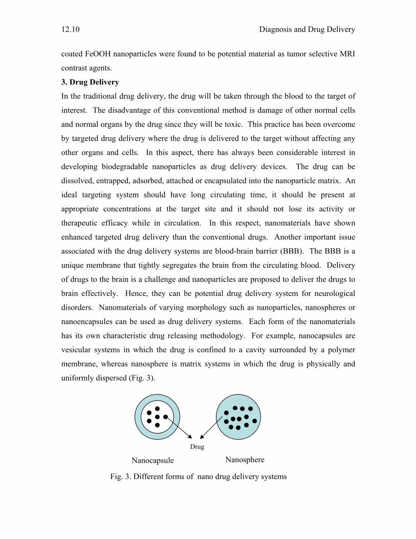
Diagnosis and Drug Delivery
12.10
coated FeOOH nanoparticles were found to be potential material as tumor selective MRI
contrast agents.
3. Drug Delivery
In the traditional drug delivery, the drug will be taken through the blood to the target of
interest. The disadvantage of this conventional method is damage of other normal cells
and normal organs by the drug since they will be toxic. This practice has been overcome
by targeted drug delivery where the drug is delivered to the target without affecting any
other organs and cells. In this aspect, there has always been considerable interest in
developing biodegradable nanoparticles as drug delivery devices. The drug can be
dissolved, entrapped, adsorbed, attached or encapsulated into the nanoparticle matrix. An
ideal targeting system should have long circulating time, it should be present at
appropriate concentrations at the target site and it should not lose its activity or
therapeutic efficacy while in circulation. In this respect, nanomaterials have shown
enhanced targeted drug delivery than the conventional drugs. Another important issue
associated with the drug delivery systems are blood-brain barrier (BBB). The BBB is a
unique membrane that tightly segregates the brain from the circulating blood. Delivery
of drugs to the brain is a challenge and nanoparticles are proposed to deliver the drugs to
brain effectively. Hence, they can be potential drug delivery system for neurological
disorders. Nanomaterials of varying morphology such as nanoparticles, nanospheres or
nanoencapsules can be used as drug delivery systems. Each form of the nanomaterials
has its own characteristic drug releasing methodology. For example, nanocapsules are
vesicular systems in which the drug is confined to a cavity surrounded by a polymer
membrane, whereas nanosphere is matrix systems in which the drug is physically and
uniformly dispersed (Fig. 3).
Fig. 3. Different forms of nano drug delivery systems
Nanosphere Nanocapsule
Drug
Frontiers in Chemistry
12.11
Drug delivery systems include nanoparticles, ceramic nanoparticles, micelles, polymeric
micelles, dendrimers and liposomes. These systems are in general polymeric and
nanosize. Ceramic nanoparticles such as organically modified silica nanoparticles
entrapped with anticancer drug, 2-devinyl-2-(1-hexyloxyethyl) pyropheophorbide have
been used to damage cancer cells.
3. 1. Various drug delivery systems
3. 1. 1 Nanoparticles
The advantages of using nanoparticles for drug delivery result from their interesting
properties. Due to their small size, nanoparticles can penetrate through smaller
capillaries and are taken up by cells, which allow efficient drug accumulation at the target
sites. The use of biodegradable materials for nanoparticle preparation allows sustained
drug release within the target site over a period of days or even weeks. Also,
nanoparticles have the potential to overcome the Blood-Brain Barrier (BBB) which is a
common problem in several drugs. Nanoparticles also protect the entrapped drug from
gastrointestinal interferences. All these allow to reduction of dose and dosing frequency
thereby reducing the side effects. Polymer nanoparticles such as PLGA (poly (lactide-co-
glycolide)), PLA (polylactic acid) have been reported for sustained drug delivery of
estradiol. There are reports of use of PLGA for gene therapy and protein delivery.
Carbon nanotubes have also been used in cancer therapy. Carbon nanotubes carry small
interfering RNA into the tumor cells where they not only silenced the target gene but also
inhibited the prolifereation of cancer cells in vitro and suppressed tumor growth in mouse
models.
3. 1. 2. Liposomes
Liposomes are vesicles made up of a lipid bilayer, resembling tiny cells with a cell
membrane but nothing in the core. There are many different type of lipids with different
head groups, different fatty acid chain lengths, and different melting temperatures (Tm).
Hence, by manipulating the formulation of liposomes, they can be constructed to be
temperature or pH sensitive to permit controlled release of their contents. Drug
molecules can be encapsulated and solubilized within the bilayers. Certain proteins can
be incorporated in the membrane of the liposome, which act as size- selective filters only
allowing the diffusion of small solutes such as ions, nutrients and antibiotics. Thus,
Diagnosis and Drug Delivery
12.12
drugs encapsulated within a liposome ‘nanocage’ that has been functionalized with
channel proteins, are effectively protected from premature degradation.
3. 1. 3. Micelles
Micellar systems are useful for the delivery of water insoluble drugs. Micelles have a
fairly narrow distribution in the nanometer range and are characterized by their unique
core shell architecture, in which hydrophobic segments are segregated from the aqueous
exterior.
3. 1.4. Dendrimers
Dendritic architecture is one of the most pervasive topologies observed throughout
biological systems at virtually all dimensional length scales. This architecture is found at
the meter scale in tree branching and roots, on the centimeter and millimeter scales in
circulatory topologies in the human anatomy such as lungs, kidney, liver, and spleen, and
on the micrometer scale in cerebral neurons. The synthesis of dendrimers offers the
opportunity to generate monodisperse, structure-controlled macromolecular architectures
similar to those observed in biological systems. Dendrimers may be visualized as
consisting of three critical architectural domains: (i) the multivalent surface, containing a
larger number of potentially reactive/passive sites (nano-scaffolding), (ii) the interior
shells (i.e., branch cell layers defined by dendrons) surrounding the core, and (iii) the
core to which the dendrons are attached. The two latter domains represent well-defined
nano-environments, which are protected from the outside by the dendrimer surface
(nanoscale containers) in the case of higher generation dendrimers. These three domains
can be tailored for a specific purpose, i.e., to function as a dendritic sensor, drug carrier,
or as a drug. The high density of exo-presented surface functionalities makes the
dendritic surface well-suited as a nano-scaffold where the close proximity of functional
groups is important (polyvalency) or for receptor mediated targeting purposes. The
interior is well-suited for host–guest interaction and encapsulation of guest molecules.
Dendrimers are widely studied for its application as drug carriers for cancer therapy and
for the delivery of DNA. Citric acid- polyethylene glycol- citric acid triblock dendrimers
can function as drug delivery system for drugs such as 5-aminosalicylic acid, pyridine
and mefenamic acid.
3. 2. Thermal ablation of cells using nanoparticles
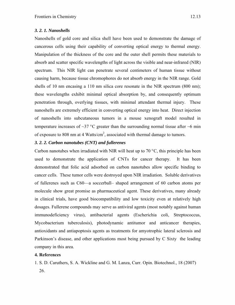
Frontiers in Chemistry
12.13
3. 2. 1. Nanoshells
Nanoshells of gold core and silica shell have been used to demonstrate the damage of
cancerous cells using their capability of converting optical energy to thermal energy.
Manipulation of the thickness of the core and the outer shell permits these materials to
absorb and scatter specific wavelengths of light across the visible and near-infrared (NIR)
spectrum. This NIR light can penetrate several centimeters of human tissue without
causing harm, because tissue chromophores do not absorb energy in the NIR range. Gold
shells of 10 nm encasing a 110 nm silica core resonate in the NIR spectrum (800 nm);
these wavelengths exhibit minimal optical absorption by, and consequently optimum
penetration through, overlying tissues, with minimal attendant thermal injury. These
nanoshells are extremely efficient in converting optical energy into heat. Direct injection
of nanoshells into subcutaneous tumors in a mouse xenograft model resulted in
temperature increases of ~37 °C greater than the surrounding normal tissue after ~6 min
of exposure to 808 nm at 4 Watts/cm2, associated with thermal damage to tumors.
3. 2. 2. Carbon nanotubes (CNT) and fullerenes
Carbon nanotubes when irradiated with NIR will heat up to 70 °C, this principle has been
used to demonstrate the application of CNTs for cancer therapy. It has been
demonstrated that folic acid adsorbed on carbon nanotubes allow specific binding to
cancer cells. These tumor cells were destroyed upon NIR irradiation. Soluble derivatives
of fullerenes such as C60—a soccerball– shaped arrangement of 60 carbon atoms per
molecule show great promise as pharmaceutical agent. These derivatives, many already
in clinical trials, have good biocompatibility and low toxicity even at relatively high
dosages. Fullerene compounds may serve as antiviral agents (most notably against human
immunodeficiency virus), antibacterial agents (Escherichia coli, Streptococcus,
Mycobacterium tuberculosis), photodynamic antitumor and anticancer therapies,
antioxidants and antiapoptosis agents as treatments for amyotrophic lateral sclerosis and
Parkinson’s disease, and other applications most being pursued by C Sixty the leading
company in this area.
4. References
1. S. D. Caruthers, S. A. Wickline and G. M. Lanza, Curr. Opin. Biotechnol., 18 (2007)
26.

Diagnosis and Drug Delivery
12.14
2. C. Sanchez, B. Julian, P. Belleville and M. Popall, J. Mater. Chem., 15 (2005) 3559
3. A. Vaseashta and D. Dimova- Malinovska, Sci. Technol. Adv. Mat., 6 (2005) 312
4. J. Wang, Biosens. Bioelectron., 21 (2006) 1887
5. A. L. Simonian, T. A. Good, S. S. Wang and J. R. Wild, Anal. Chim. Acta, 534 (2005)
69
6. X. X. Xiao, Q. Q. He and K. L. Huang, Medical Hypotheses, 68 (2007) 680
7. J. Manso, M. L. Mena, P. Y. Sedeno and J. Pingarron, J. Electroanal. Chem., 603
(2007) 1
8. Y. H. Xu, J. Bai and J. P. Wang, J. Magn.Magn. Mater., 311 (2007) 131
9. R. E. Bailey, A. M. Smith and S. Nie, Physica E 25 (2004) 1
10. J. Panyam and V. Labhasetwar, Adv. Drug. Deliv. Rev., 55 (2003) 329
Chapter - 13 POLLUTION CONTROL
S. Chandravathanam
Introduction
Substances not naturally found in the air or at greater concentrations or in different
locations from usual are referred to as 'pollutants'.
Pollution is the introduction of toxic substances arising mainly from human
activities like, combustion of fossil fuels, domestic, industrial and agricultural waste
generation, into the air, water or ground that are damaging to human health and
ecosystems. Pollution is also the consequence of a natural disaster. But it accounts to very
lesser extent and rate, to which nature can able to tolerate and recover. But the very fast
industriallization and life style far encompassed the nature’s recovery rate.
The major forms of pollution include:
Air pollution, the release of chemicals and particulates into the atmosphere.
Common examples include carbon monoxide, sulfur dioxide, chlorofluorocarbons
(CFCs), and nitrogen oxides produced by industry and motor vehicles.
Photochemical ozone and smog are created as nitrogen oxides and hydrocarbons
react to sunlight.
Water pollution via surface runoff and industrial wastewater discharges into the
surface water sources.
Increasing quantities of trash or garbages and biological solid wastes.
Soil contamination with chemicals spill.
Radioactive contamination, added in the wake of 20th-century discoveries in
atomic physics.
Noise pollution, which encompasses roadway noise, aircraft noise, industrial
noise as well as high intensity sonar.
Light pollution, which includes light trespass, over-illumination and astronomical
interference.
Thermal Pollution, with the drastic change of temperature of natural water bodies.
Pollution Control
13.2
Air Pollution
In the past, only those in large cities had to worry about the air they breathed. Most took
for granted that clean, fresh air would always be available. But today, nearly everyone on
earth breathes a cocktail of poisons that is nearly worse than the tailpipe of a car. There
are many substances in the air which may impair the health of plants and animals
(including humans), or reduce visibility. These arise both from natural processes ( like
storm, volcanic eruptions, etc.) and human activity.
Pollutants can be classified as either primary or secondary. Primary pollutants are
substances directly produced by a process, such as ash from a volcanic eruption or the
carbon monoxide gas from a motor vehicle exhaust. Secondary pollutants are not emitted.
Rather, they form in the air when primary pollutants react or interact themselves. An
important example of a secondary pollutant is ground level ozone, one of the many
secondary pollutants that make up photochemical smog. Some pollutants may be both
primary and secondary. That is, they are both emitted directly and formed from other
primary pollutants.
Primary pollutants produced by human activities include:
� oxides of sulfur, nitrogen and carbon.
� organic compounds, such as hydrocarbons (fuel vapours and solvents)
� particulate matter, such as smoke and dust
� metal oxides, especially those of lead, cadmium, copper and iron
� chlorofluorocarbons (CFCs)
Secondary pollutants include some particles formed from gaseous primary
pollutants. For example compounds in photochemical smog, such as nitrogen
dioxide, ground level ozone and peroxyacetyl nitrate (PAN).
The six main air pollutants are called as ‘Criteria air pollutants’ and are common
throughout the globe. These pollutants can injure health, harm the environment and cause
property damage. The six criteria pollutants are Carbon monoxide, Lead, Nitrogen
dioxide (one of several Nitrogen oxides), Ozone (formed from precursor Volatile organic
compounds), Particulate Matter and Sulfur dioxide.
Carbon monoxide (CO)
Frontiers in Chemistry
13.3
Carbon monoxide (CO) is a colorless, odorless and poisonous gas produced by
incomplete burning of carbon in fuels. When CO enters the blood stream it reduces the
delivery of oxygen to the body's organs and tissues. Health threats are most serious for
those who suffer from cardiovascular disease. Exposure to elevated CO levels can cause
impairment of visual perception, manual dexterity, learning ability and performance of
complex tasks. 77% of the nationwide CO emissions are from transportation sources.
Other major CO sources are wood burning stoves, incinerators and industrial sources.
Lead (Pb)
Lead (Pb) is a widely used metal that, once released to the environment, can contaminate
air, food, water, or soil. Exposures to even small amounts of lead over a long time can
accumulate to reach harmful levels. Harmful effects may therefore develop gradually
without warning. Short-term exposure to high levels of lead may also cause harm. Lead
can adversely affect the nervous, reproductive, digestive, cardiovascular blood-forming
systems, and the kidney. In men, adverse reproductive effects include reduced sperm
count and abnormal sperm. In women, adverse reproductive effects include reduced
fertility, still-birth, or miscarriage. Children are a sensitive population as they absorb lead
more readily and their developing nervous system puts them at increased risk for learning
disabilities.
Lead gasoline additives, non-ferrous smelters, and battery plants are the most
significant contributors to Pb emissions into the atmosphere. In 1993 transportation
sources contributed 33% of the annual emissions, down substantially from 81% in 1985.
Total Pb emissions from all sources dropped from 20,100 tons in 1985 to 4,900 tons in
1993. The decrease in Pb emissions from cars and trucks shifting to lead-free gasoline
accounts for essentially this entire decline.
Nitrogen dioxide (NO2)
Nitrogen dioxide (NO2) is a brownish, highly reactive gas that is present in all urban
atmospheres. NO2 can irritate the lungs, cause bronchitis and pneumonia, and lower
resistance to respiratory infections. The major mechanism for the formation of NO2 in the
atmosphere is the oxidation of nitric oxide (NO), which is produced by most combustion
processes.

Pollution Control
13.4
Nitrogen oxides (NOx)
Nitrogen oxides (NOx) include various nitrogen compounds like nitrogen dioxide (NO2)
and nitric oxide (NO). These compounds play an important role in the atmospheric
reactions that create ozone (O3) and acid rain. Individually, they may affect ecosystems,
both on land and in water. NOx forms when fuels are burned at high temperatures. The
two major emission sources are transportation vehicles and stationary combustion sources
such as electric utility and industrial boilers.
Ozone (O3)
Ozone (O3) is the major component of smog. Although O3 in the upper atmosphere is
beneficial because it shields the earth from the sun's harmful ultraviolet radiation, high
concentrations of O3 at ground level are a major health and environmental concern. The
reactivity of O3 causes health problems because it damages lung tissue, reduces lung
function and sensitizes the lungs to other irritants. Scientific evidence indicates that
ambient levels of O3 not only affect people with impaired respiratory systems, such as
asthmatics, but healthy adults and children as well. Exposure to O3 for several hours at
relatively low concentrations has been found to significantly reduce lung function and
induce respiratory inflammation in normal, healthy people during exercise.
O3 is not usually emitted directly but is formed through complex chemical
reactions in the atmosphere. Precursor compounds like volatile organic compounds
(VOC) and oxides of nitrogen (NOx) react to form O3 in the presence of sunlight. These
reactions are stimulated by ultraviolet radiation and temperature, so peak O3 levels
typically occur during the warmer times of the day and year.
Particulate matter (PM)
Particulate matter (PM) is a mixture of particles that can adversely affect human health,
damage materials and form atmospheric haze that degrades visibility. PM is usually
divided into different classes based on size, as total suspended matter (TSP), PM-10
(particles less than 10 microns in aerodynamic diameter) and PM-2.5 (particles less than
2.5 microns). In general, the smallest particles pose the highest human health risks. PM
exposure can affect breathing, aggravate existing respiratory and cardiovascular disease,
alter the body's defense systems against foreign materials, and damage lung tissue,
contributing to cancer and premature death. Individuals with chronic obstructive
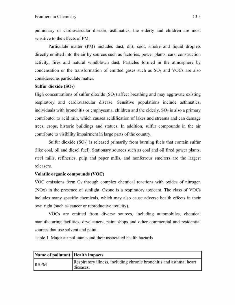
Frontiers in Chemistry
13.5
pulmonary or cardiovascular disease, asthmatics, the elderly and children are most
sensitive to the effects of PM.
Particulate matter (PM) includes dust, dirt, soot, smoke and liquid droplets
directly emitted into the air by sources such as factories, power plants, cars, construction
activity, fires and natural windblown dust. Particles formed in the atmosphere by
condensation or the transformation of emitted gases such as SO2 and VOCs are also
considered as particulate matter.
Sulfur dioxide (SO2)
High concentrations of sulfur dioxide (SO2) affect breathing and may aggravate existing
respiratory and cardiovascular disease. Sensitive populations include asthmatics,
individuals with bronchitis or emphysema, children and the elderly. SO2 is also a primary
contributor to acid rain, which causes acidification of lakes and streams and can damage
trees, crops, historic buildings and statues. In addition, sulfur compounds in the air
contribute to visibility impairment in large parts of the country.
Sulfur dioxide (SO2) is released primarily from burning fuels that contain sulfur
(like coal, oil and diesel fuel). Stationary sources such as coal and oil fired power plants,
steel mills, refineries, pulp and paper mills, and nonferrous smelters are the largest
releasers.
Volatile organic compounds (VOC)
VOC emissions form O3 through complex chemical reactions with oxides of nitrogen
(NOx) in the presence of sunlight. Ozone is a respiratory toxicant. The class of VOCs
includes many specific chemicals, which may also cause adverse health effects in their
own right (such as cancer or reproductive toxicity).
VOCs are emitted from diverse sources, including automobiles, chemical
manufacturing facilities, drycleaners, paint shops and other commercial and residential
sources that use solvent and paint.
Table 1. Major air pollutants and their associated health hazards
Name of pollutant Health impacts
RSPM Respiratory illness, including chronic bronchitis and asthma; heart diseases.

Pollution Control
13.6
SO2 Heart diseases; respiratory problems including pulmonary emphysema, cancer, eye burning, headache, etc.
NO2 Lung irritation, viral infection, airway resistance, chest tightness, etc.
SPM Pneumoconiosis, restrictive lung diseases, asthma, cancer, etc.
Benzene It causes immunotoxicity, carcinogenicity, asthma, anemia, unconsciousness etc.
Ozone Impaired lung function, chest pains, coughing, irritation of eyes, nose etc.
CO CO poisoning cause cherry lips, unconsciousness, death by asphyxiation etc.
Lead It causes decreased hemoglobin synthesis, anemia, damage the nervous and renal (kidney) systems etc.
RSPM - Respirable suspended particulate matter
SPM - Suspended particulate matter
Table 1 describes the health impacts of main air pollutants and Table-2 gives a measure
of major air pollutants present in few Indian cities.
Table 2. Measure of air Pollution in few Indian cities
PARTICULATE POLLUTION
GAS POLLUTION CITY
RSPM (µg/M3) SPM (µg/M3) SO2 (µg/M3) NO2 (µg/M3)
Ahmedabad (Ashram Road) - 443 2 30
Bangalore (J.C. Road) - 204 11 16
Chandigarh (Sector 7) - 318 7 22
Chennai (T. Nagar) - 141 12 8
Delhi (Lajpat Nagar) - 426 12 26
Guwahati (Silpukhuri) - - - -
Hyderabad (Sr. Nagar) - 219 5 19
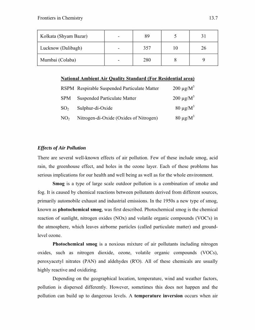
Frontiers in Chemistry
13.7
Kolkata (Shyam Bazar) - 89 5 31
Lucknow (Dalibagh) - 357 10 26
Mumbai (Colaba) - 280 8 9
National Ambient Air Quality Standard (For Residential area)
RSPM Respirable Suspended Particulate Matter 200 µg/M3
SPM Suspended Particulate Matter 200 µg/M3
SO2 Sulphur-di-Oxide 80 µg/M3
NO2 Nitrogen-di-Oxide (Oxides of Nitrogen) 80 µg/M3
Effects of Air Pollution
There are several well-known effects of air pollution. Few of these include smog, acid
rain, the greenhouse effect, and holes in the ozone layer. Each of these problems has
serious implications for our health and well being as well as for the whole environment.
Smog is a type of large scale outdoor pollution is a combination of smoke and
fog. It is caused by chemical reactions between pollutants derived from different sources,
primarily automobile exhaust and industrial emissions. In the 1950s a new type of smog,
known as photochemical smog, was first described. Photochemical smog is the chemical
reaction of sunlight, nitrogen oxides (NOx) and volatile organic compounds (VOC's) in
the atmosphere, which leaves airborne particles (called particulate matter) and ground-
level ozone.
Photochemical smog is a noxious mixture of air pollutants including nitrogen
oxides, such as nitrogen dioxide, ozone, volatile organic compounds (VOCs),
peroxyacetyl nitrates (PAN) and aldehydes (R'O). All of these chemicals are usually
highly reactive and oxidizing.
Depending on the geographical location, temperature, wind and weather factors,
pollution is dispersed differently. However, sometimes this does not happen and the
pollution can build up to dangerous levels. A temperature inversion occurs when air
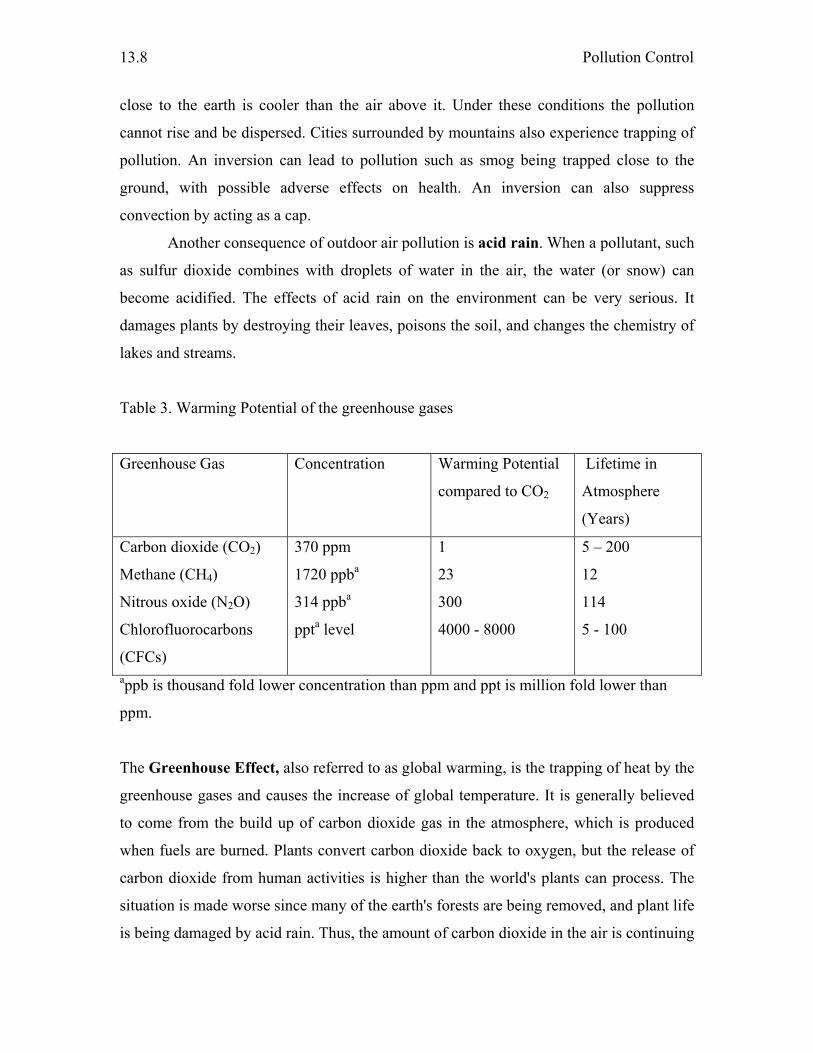
Pollution Control
13.8
close to the earth is cooler than the air above it. Under these conditions the pollution
cannot rise and be dispersed. Cities surrounded by mountains also experience trapping of
pollution. An inversion can lead to pollution such as smog being trapped close to the
ground, with possible adverse effects on health. An inversion can also suppress
convection by acting as a cap.
Another consequence of outdoor air pollution is acid rain. When a pollutant, such
as sulfur dioxide combines with droplets of water in the air, the water (or snow) can
become acidified. The effects of acid rain on the environment can be very serious. It
damages plants by destroying their leaves, poisons the soil, and changes the chemistry of
lakes and streams.
Table 3. Warming Potential of the greenhouse gases
Greenhouse Gas
Concentration Warming Potential
compared to CO2
Lifetime in
Atmosphere
(Years)
Carbon dioxide (CO2)
Methane (CH4)
Nitrous oxide (N2O)
Chlorofluorocarbons
(CFCs)
370 ppm
1720 ppba
314 ppba
ppta level
1
23
300
4000 - 8000
5 – 200
12
114
5 - 100
appb is thousand fold lower concentration than ppm and ppt is million fold lower than
ppm.
The Greenhouse Effect, also referred to as global warming, is the trapping of heat by the
greenhouse gases and causes the increase of global temperature. It is generally believed
to come from the build up of carbon dioxide gas in the atmosphere, which is produced
when fuels are burned. Plants convert carbon dioxide back to oxygen, but the release of
carbon dioxide from human activities is higher than the world's plants can process. The
situation is made worse since many of the earth's forests are being removed, and plant life
is being damaged by acid rain. Thus, the amount of carbon dioxide in the air is continuing
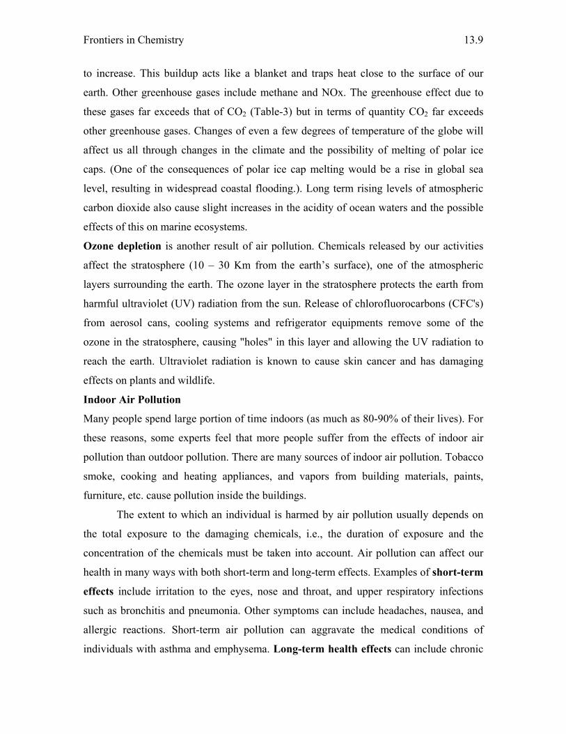
Frontiers in Chemistry
13.9
to increase. This buildup acts like a blanket and traps heat close to the surface of our
earth. Other greenhouse gases include methane and NOx. The greenhouse effect due to
these gases far exceeds that of CO2 (Table-3) but in terms of quantity CO2 far exceeds
other greenhouse gases. Changes of even a few degrees of temperature of the globe will
affect us all through changes in the climate and the possibility of melting of polar ice
caps. (One of the consequences of polar ice cap melting would be a rise in global sea
level, resulting in widespread coastal flooding.). Long term rising levels of atmospheric
carbon dioxide also cause slight increases in the acidity of ocean waters and the possible
effects of this on marine ecosystems.
Ozone depletion is another result of air pollution. Chemicals released by our activities
affect the stratosphere (10 – 30 Km from the earth’s surface), one of the atmospheric
layers surrounding the earth. The ozone layer in the stratosphere protects the earth from
harmful ultraviolet (UV) radiation from the sun. Release of chlorofluorocarbons (CFC's)
from aerosol cans, cooling systems and refrigerator equipments remove some of the
ozone in the stratosphere, causing "holes" in this layer and allowing the UV radiation to
reach the earth. Ultraviolet radiation is known to cause skin cancer and has damaging
effects on plants and wildlife.
Indoor Air Pollution
Many people spend large portion of time indoors (as much as 80-90% of their lives). For
these reasons, some experts feel that more people suffer from the effects of indoor air
pollution than outdoor pollution. There are many sources of indoor air pollution. Tobacco
smoke, cooking and heating appliances, and vapors from building materials, paints,
furniture, etc. cause pollution inside the buildings.
The extent to which an individual is harmed by air pollution usually depends on
the total exposure to the damaging chemicals, i.e., the duration of exposure and the
concentration of the chemicals must be taken into account. Air pollution can affect our
health in many ways with both short-term and long-term effects. Examples of short-term
effects include irritation to the eyes, nose and throat, and upper respiratory infections
such as bronchitis and pneumonia. Other symptoms can include headaches, nausea, and
allergic reactions. Short-term air pollution can aggravate the medical conditions of
individuals with asthma and emphysema. Long-term health effects can include chronic

Pollution Control
13.10
respiratory disease, lung cancer, heart disease, and even damage to the brain, nerves,
liver, or kidneys. Continual exposure to air pollution affects the lungs of growing
children and may aggravate or complicate medical conditions in the elderly.
Hazardous air pollutants
Hazardous air pollutants, also known as Toxic air pollutants, are those pollutants that
are known or suspected to cause cancer or other serious health effects such as
reproductive effects or birth defects or adverse environmental effects. Examples of toxic
air pollutants include benzene, which is found in gasoline; perchlorethlyene, which is
emitted from some dry cleaning facilities; and methylene chloride, which is used as a
solvent and paint stripper by a number of industries. Examples of other listed air toxics
include dioxin, asbestos, toluene, PAHs (Polycyclic aromatic hydrocarbons), PCBs
(Polychlorinated biphenyls), and metals such as cadmium, mercury, chromium, and lead
compounds. In addition to exposure from breathing air toxics, some toxic air pollutants
such as mercury can deposit onto soil or surface waters, where these are taken up by
plants and ingested by animals and are eventually magnified up through the food chain.
Toxics essentially include all air pollutants other than the criteria pollutants, i.e.,
NOx, SOx, CO, Pb, PM and O3. Most air toxics originate from human made sources,
including mobile sources (e.g., cars, trucks, buses) and stationary sources (e.g., factories,
refineries, power plants), as well as indoor sources (e.g., paints, shoe polish, cleaning
solutions etc.).
Air Pollution Episodes
The worst short term civilian pollution crisis was in India, the 1984 Bhopal Disaster.
Leaked industrial vapors from the Union Carbide factory, belonging to Union Carbide,
Inc., U.S.A., killed more than 2,000 people outright and injured anywhere from 150,000
to 600,000 others, some 6,000 of whom would later die from their injuries. The United
Kingdom suffered its worst air pollution event when the December 4th Great Smog of
1952 formed over London. In six days more than 4,000 died, and 8,000 more died within
the following months. An accidental leak of anthrax spores from a biological warfare
laboratory in the former USSR in 1979 near Sverdlovsk is believed to have been the
cause of hundreds of civilian deaths. The worst single incident of air pollution in the
Frontiers in Chemistry
13.11
United States of America occurred in Donora, Pennsylvania in late October, 1948, death
of about 80 people and over 7,000 injured due to the accumulation of pollutants caused
by air inversion.
Pollution Prevention
Both indoor and outdoor pollution need to be controlled and/or prevented.
Various regulatory measures have been put on as a result of the breaking of air pollution
episodes. United States Congress passed the Clean Air Act in 1963, the Air Quality Act
in 1967, the Clean Air Act Extension in 1970, and Clean Air Act Amendments in 1977
and 1990. The Air (Prevention and Control of Pollution) Act – 1981, 1982 and the
amendment Act 1987 are few of the important legislative measures taken in India
towards air pollution control. The regulatory agencies play an essential role in reducing
and preventing air pollution in the environment.
Air Pollution Control
The following items are commonly used as pollution control devices by industry or
transportation devices. They can either destroy contaminants or remove them from an
exhaust stream before it is emitted into the atmosphere.
Particulate control is done through Mechanical collectors (dust cyclones,
multicyclones), Electrostatic precipitators, Fabric filters (baghouses) and Particulate
scrubbers.
NOx control is done through Low NOx burners, Selective catalytic or non-catalytic
reduction, NOx scrubbers, Exhaust gas recirculation and Catalytic converter (also for
VOC control).
VOC abatement is by Adsorption systems, such as activated carbon, Flaring, Thermal
and catalytic oxidizers, Biofilters, Absorption (scrubbing) and Cryogenic condensers.
Acidic Gas/SO2 control is through Wet or dry scrubbers and Flue gas desulfurization.
Water Pollution
The giant lakes of water or aquifers are either quickly drying up or being left undrinkable
from pollution. The United Nations predicts that by 2050 the entire world’s usable
freshwater will be gone! In Tirupur, Tamil Nadu, 737 textile units consume around 90
million liters or 7,500 tanker loads of water every day. The unregulated mining of water
has sent groundwater levels plummeting to below 800 feet.
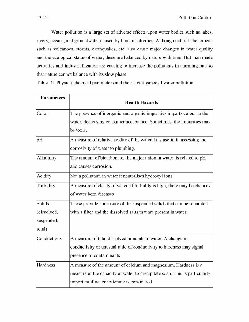
Pollution Control
13.12
Water pollution is a large set of adverse effects upon water bodies such as lakes,
rivers, oceans, and groundwater caused by human activities. Although natural phenomena
such as volcanoes, storms, earthquakes, etc. also cause major changes in water quality
and the ecological status of water, these are balanced by nature with time. But man made
activities and industriallization are causing to increase the pollutants in alarming rate so
that nature cannot balance with its slow phase.
Table 4. Physico-chemical parameters and their significance of water pollution
Parameters
Health Hazards
Color The presence of inorganic and organic impurities imparts colour to the
water, decreasing consumer acceptance. Sometimes, the impurities may
be toxic.
pH A measure of relative acidity of the water. It is useful in assessing the
corrosivity of water to plumbing.
Alkalinity The amount of bicarbonate, the major anion in water, is related to pH
and causes corrosion.
Acidity Not a pollutant, in water it neutralises hydroxyl ions
Turbidity A measure of clarity of water. If turbidity is high, there may be chances
of water born diseases
Solids
(dissolved,
suspended,
total)
These provide a measure of the suspended solids that can be separated
with a filter and the dissolved salts that are present in water.
Conductivity A measure of total dissolved minerals in water. A change in
conductivity or unusual ratio of conductivity to hardness may signal
presence of contaminants
Hardness A measure of the amount of calcium and magnesium. Hardness is a
measure of the capacity of water to precipitate soap. This is particularly
important if water softening is considered
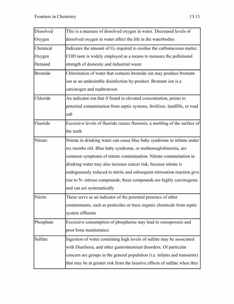
Frontiers in Chemistry
13.13
Dissolved
Oxygen
This is a measure of dissolved oxygen in water. Decreased levels of
dissolved oxygen in water affect the life in the waterbodies
Chemical
Oxygen
Demand
Indicates the amount of O2 required to oxidise the carbonaceous matter.
COD taste is widely employed as a means to measure the pollutional
strength of domestic and industrial waste
Bromide Chlorination of water that contains bromide ion may produce bromate
ion as an undesirable disinfection by-product. Bromate ion is a
carcinogen and nephrotoxin
Chloride An indicator ion that if found in elevated concentration, points to
potential contamination from septic systems, fertilizer, landfills, or road
salt
Fluoride Excessive levels of fluoride causes fluorosis, a mottling of the surface of
the teeth
Nitrate Nitrate in drinking water can cause blue baby syndrome in infants under
six months old. Blue baby syndrome, or methemoglobinemia, are
common symptoms of nitrate contamination. Nitrate contamination in
drinking water may also increase cancer risk, because nitrate is
endogenously reduced to nitrite and subsequent nitrosation reaction give
rise to N- nitroso compounds; these compounds are highly carcinogenic
and can act systematically
Nitrite These serve as an indicator of the potential presence of other
contaminants, such as pesticides or trace organic chemicals from septic
system effluents
Phosphate Excessive consumption of phosphorus may lead to osteoporosis and
poor bone maintenance
Sulfate Ingestion of water containing high levels of sulfate may be associated
with Diarrhoea, and other gastrointestinal disorders. Of particular
concern are groups in the general population (i.e. infants and transients)
that may be at greater risk from the laxative effects of sulfate when they
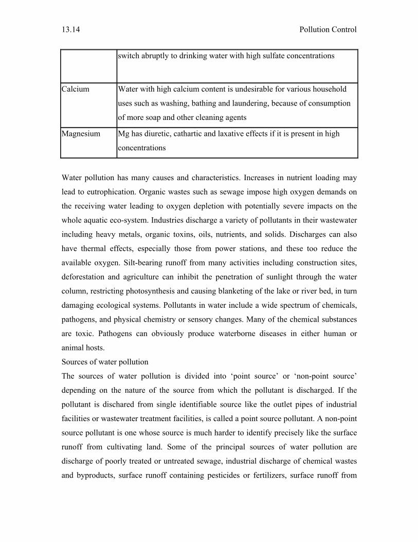
Pollution Control
13.14
switch abruptly to drinking water with high sulfate concentrations
Calcium Water with high calcium content is undesirable for various household
uses such as washing, bathing and laundering, because of consumption
of more soap and other cleaning agents
Magnesium Mg has diuretic, cathartic and laxative effects if it is present in high
concentrations
Water pollution has many causes and characteristics. Increases in nutrient loading may
lead to eutrophication. Organic wastes such as sewage impose high oxygen demands on
the receiving water leading to oxygen depletion with potentially severe impacts on the
whole aquatic eco-system. Industries discharge a variety of pollutants in their wastewater
including heavy metals, organic toxins, oils, nutrients, and solids. Discharges can also
have thermal effects, especially those from power stations, and these too reduce the
available oxygen. Silt-bearing runoff from many activities including construction sites,
deforestation and agriculture can inhibit the penetration of sunlight through the water
column, restricting photosynthesis and causing blanketing of the lake or river bed, in turn
damaging ecological systems. Pollutants in water include a wide spectrum of chemicals,
pathogens, and physical chemistry or sensory changes. Many of the chemical substances
are toxic. Pathogens can obviously produce waterborne diseases in either human or
animal hosts.
Sources of water pollution
The sources of water pollution is divided into ‘point source’ or ‘non-point source’
depending on the nature of the source from which the pollutant is discharged. If the
pollutant is dischared from single identifiable source like the outlet pipes of industrial
facilities or wastewater treatment facilities, is called a point source pollutant. A non-point
source pollutant is one whose source is much harder to identify precisely like the surface
runoff from cultivating land. Some of the principal sources of water pollution are
discharge of poorly treated or untreated sewage, industrial discharge of chemical wastes
and byproducts, surface runoff containing pesticides or fertilizers, surface runoff from
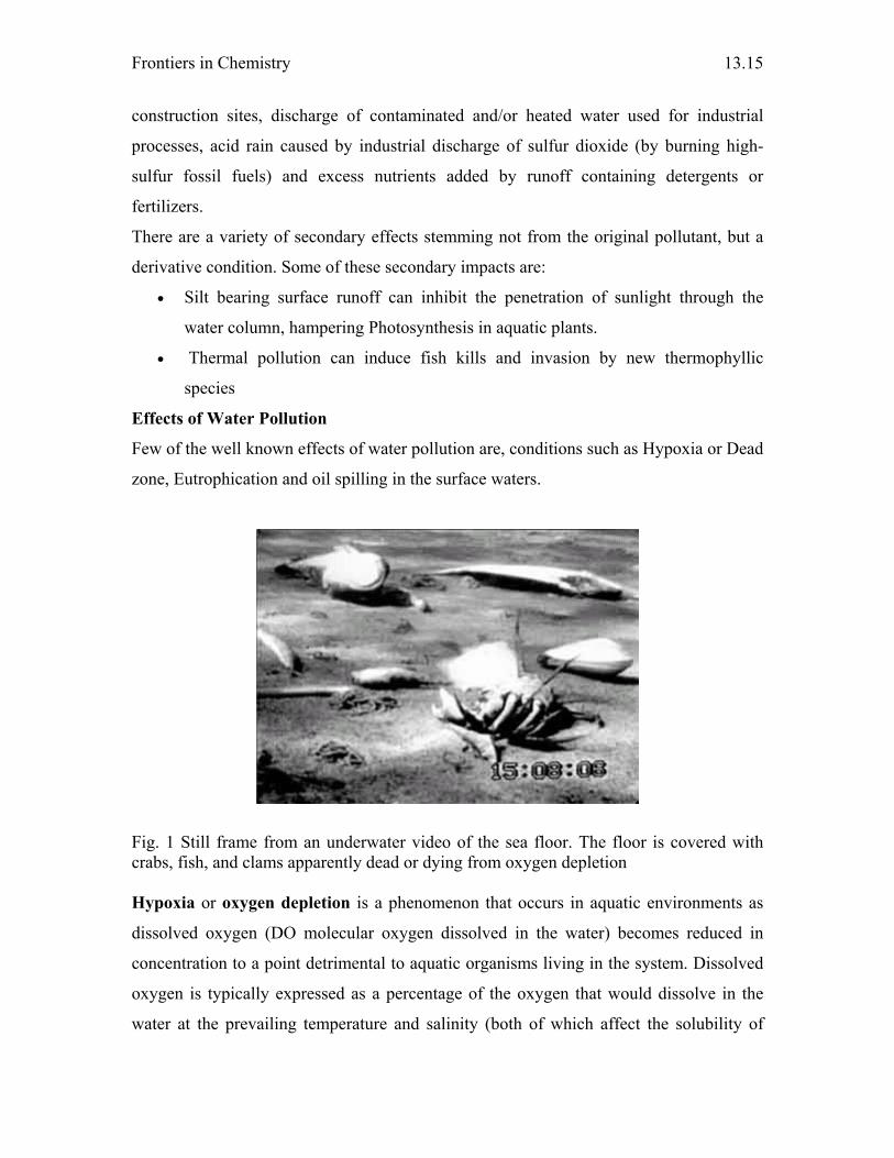
Frontiers in Chemistry
13.15
construction sites, discharge of contaminated and/or heated water used for industrial
processes, acid rain caused by industrial discharge of sulfur dioxide (by burning high-
sulfur fossil fuels) and excess nutrients added by runoff containing detergents or
fertilizers.
There are a variety of secondary effects stemming not from the original pollutant, but a
derivative condition. Some of these secondary impacts are:
• Silt bearing surface runoff can inhibit the penetration of sunlight through the
water column, hampering Photosynthesis in aquatic plants.
• Thermal pollution can induce fish kills and invasion by new thermophyllic
species
Effects of Water Pollution
Few of the well known effects of water pollution are, conditions such as Hypoxia or Dead
zone, Eutrophication and oil spilling in the surface waters.
Fig. 1 Still frame from an underwater video of the sea floor. The floor is covered with crabs, fish, and clams apparently dead or dying from oxygen depletion
Hypoxia or oxygen depletion is a phenomenon that occurs in aquatic environments as
dissolved oxygen (DO molecular oxygen dissolved in the water) becomes reduced in
concentration to a point detrimental to aquatic organisms living in the system. Dissolved
oxygen is typically expressed as a percentage of the oxygen that would dissolve in the
water at the prevailing temperature and salinity (both of which affect the solubility of
Pollution Control
13.16
oxygen in water; see oxygen saturation and underwater). An aquatic system lacking
dissolved oxygen (0% saturation) is termed anaerobic, anoxic or Dead zone; a system
with low DO of concentration, in the range between 1 and 30% DO saturation is called
hypoxic. Most fish cannot live below 30% DO saturation. A "healthy" aquatic
environment should seldom experience DO between 30 and 80%.
Eutrophication is caused by the increase in an ecosystem of chemical nutrients, typically
compounds containing nitrogen or phosphorus. It may occur on land or in water.
Eutrophication is frequently a result of nutrient pollution such as the release of sewage
effluent into natural waters (rivers or coasts) although it may also occur naturally in
situations where nutrients accumulate. When an aquatic ecosystem experiences an
increase in nutrients, species such as algae experience a population increase (called an
algal bloom). Algal blooms limit the sunlight available to bottom-dwelling organisms and
cause wide variation in the amount of dissolved oxygen in the water. Oxygen is required
by all respiring plants and animals and it is replenished in daylight by photosynthesizing
plants and algae. Under eutrophic conditions, dissolved oxygen greatly increases during
the day, but is greatly reduced after dark by the respiring algae and by microorganisms
that feed on the increasing mass of dead algae. When dissolved oxygen levels decline to
hypoxic levels, fish and other marine animals suffocate. As a result, creatures such as
fish, shrimp, and especially immobile bottom dwellers die off. In extreme cases,
anaerobic conditions ensue, promoting growth of bacteria such as Clostridium botulinum
that produces toxins deadly to birds and mammals. Zones where this occurs are known as
dead zones.
Oil spill
Studies of the Exxon Valdez oil spill, 1989 have shown that the environmental damage
caused by oil spills can be greater than that was previously thought. It was clear that the
impacts to marine life can be evident at less than one part per billion petroleum
hydrocarbons. The lighter fractions of petroleum, such as benzene and toluene, are more
toxic, but are more volatile and evaporate quickly. Heavier components of crude oil, such
as polynuclear aromatic hydrocarbons (PAHs) appear to cause the most damage; while
they are less toxic, they persist in the environment much longer than volatile components.
A heavy oil spill across the shore blankets rock-pools etc, preventing gas exchange and

Frontiers in Chemistry
13.17
eliminating light as well as directly leaching toxins into the water; it can also become
mixed deeply into pebble, shingle or sandy beaches, where it may remain for months or
even years. Well-weathered heavy oil on intertidal rocks doesn't retain serious toxicity,
for example, it will be grazed off by limpets without apparent ill-effect.
Seabirds are adversely affected as the oil penetrates and opens up the structure of
their plumage, so they become chilled, lose the ability to fly, and lose their buoyancy in
water. They are thus unable to feed normally, but ingest the oil as they attempt to preen.
They will almost inevitably die unless rescued and professionally cleaned.
Water Treatment
There are numerous processes that can be used to clean up waste waters depending on the
type and extent of contamination. Most wastewater is treated in industrial scale
wastewater treatment plants (WWTPs) which may include physical, chemical and
biological treatment processes.
Sewage treatment, or domestic wastewater treatment, is the process of
removing contaminants from wastewater, both runoff and domestic. It includes physical,
chemical and biological processes to remove physical, chemical and biological
contaminants. Its objective is to produce a wastestream (or treated effluent) and a solid
waste or sludge also suitable for discharge or reuse back into the environment.
Typically, sewage treatment involves three stages, called primary, secondary and
tertiary treatment. First, the solids are separated from the wastewater stream. Then
dissolved biological matter is progressively converted into a solid mass by using
indigenous, water-borne bacteria. Finally, the biological solids are neutralized and
disposed of or re-used. The treated water may be disinfected chemically or physically (for
example by lagooning and micro-filtration). The final effluent can be discharged into a
stream, river, bay, lagoon or wetland, or it can be used for the irrigation of a golf course,
greenway or park. If it is sufficiently clean, it can also be used for groundwater recharge.
Primary treatment
Primary treatment is to reduce oils, grease, fats, sand, grit, and coarse (settleable) solids.
This step is done entirely with machinery, hence given the name mechanical treatment.
Screening
Pollution Control
13.18
In the mechanical treatment, the influx (influent) of sewage water is screened to remove
all large objects that are deposited in the sewer system, such as rags, sticks, condoms,
sanitary towels (sanitary napkins) or tampons, cans, fruit, etc. This is most commonly
done with a manual or automated mechanically raked screen. This type of waste is
removed because it can damage the sensitive equipment in the sewage treatment plant.
Sand and grit removal
This stage typically includes a sand or grit channel where the velocity of the incoming
wastewater is carefully controlled to allow sand, grit and stones to settle but still maintain
the majority of the organic material within the flow. This equipment is called a detritor or
sand catcher. Sand, grit and stones need to be removed early in the process to avoid
damage to pumps and other equipment in the remaining treatment stages. The sand and
grit is sent to a landfill.
Sedimentation
Many plants have a sedimentation stage where the sewage is allowed to pass slowly
through large tanks, commonly called "primary clarifiers" or "primary sedimentation
tanks". The tanks are large enough that faecal solids can settle and floating material such
as grease and oils can rise to the surface and be skimmed off. The main purpose of the
primary stage is to produce a generally homogeneous liquid capable of being treated
biologically and a sludge that can be separately treated or processed. Primary settlement
tanks are usually equipped with mechanically driven scrapers that continually drive the
collected sludge towards a hopper in the base of the tank from where it can be pumped to
further sludge treatment stages.
Secondary treatment
Secondary treatment is designed to substantially decompose the biological content of the
sewage such as are derived from human waste, food waste, soaps and detergent. The
majority of municipal and industrial plants treat the settled sewage liquor using aerobic
biological processes. For this to be effective, the biota require both oxygen and a
substrate on which to live. There are number of ways in which this is done. In all these
methods, the bacteria and protozoa consume biodegradable soluble organic contaminants
(e.g. sugars, fats, organic short-chain carbon molecules, etc.) and bind much of the less
soluble fractions into floc. Secondary treatment systems are classified as fixed film or
Frontiers in Chemistry
13.19
suspended growth. Fixed-film treatment process including trickling filters and rotating
biological contactors where the biomass grows on media and the sewage passes over its
surface. In suspended growth systems such as activated sludge the biomass is well
mixed with the sewage can be operated in a smaller space than fixed-film systems that
treat the same amount of water. However, fixed-film systems are more able to cope with
drastic changes in the amount of biological material and can provide higher removal rates
for organic material and suspended solids than suspended growth systems.
Secondary sedimentation
The final step in the secondary treatment stage is to settle out the biological floc or filter
material and produce sewage water containing very low levels of organic material and
suspended matter.
Tertiary treatment
Wastewater may contain high levels of the nutrients nitrogen and phosphorus. Excessive
release of these nutrients to the environment can lead to eutrophication, which can in turn
encourage the overgrowth of weeds, algae, and cyanobacteria (blue-green algae) which
further leads to hypoxic or anoxic contitions in water boby. In addition to causing
deoxygenation, some algal species produce toxins that contaminate drinking water
supplies. Separate treatment processes are required to remove nitrogen and phosphorus as
it needs longer residential time than the oxidation of carbonaceous material in the
secondary treatment.
Nitrogen removal
The removal of nitrogen is effected through the biological oxidation of nitrogen from
ammonia (nitrification) to nitrate, followed by denitrification, the reduction of nitrate to
nitrogen gas. Nitrogen gas is released to the atmosphere and thus removed from the
water.
Phosphorus removal
Phosphorus can be removed biologically in a process called enhanced biological
phosphorus removal. In this process, specific bacteria, called polyphosphate
accumulating organisms, are selectively enriched and allowed to accumulate large
quantities of phosphorus within their cells (up to 20% of their mass). When the biomass
enriched in these bacteria is separated from the treated water, these biosolids have a high

Pollution Control
13.20
fertilizer value. Phosphorus removal can also be achieved by chemical precipitation,
usually with salts of iron (e.g. ferric chloride) or aluminum (e.g. alum). The resulting
chemical sludge is difficult to handle and the added chemicals can be expensive. Despite
this, chemical phosphorus removal requires significantly smaller equipment than
biological removal, is easier to operate and can be more reliable in areas that have
wastewater compositions that make biological phosphorus removal difficult.
Disinfection
The purpose of disinfection in the treatment of wastewater is to substantially reduce the
number of microrganisms in the water to be discharged back into the environment. The
effectiveness of disinfection depends on the quality of the water being treated (e.g.,
cloudiness, pH, etc.), the type of disinfection being used, the disinfectant dosage
(concentration and time), and other environmental variables. Cloudy water will be treated
less successfully since solid matter can shield organisms, especially from ultraviolet light
or if contact times are low. Generally, short contact times, low doses and high flows all
militate against effective disinfection. Common methods of disinfection include ozone,
chlorine, or ultraviolet light. Chloramine, which is used for drinking water, is not used in
wastewater treatment because of its persistence.
Chlorination remains the most common form of wastewater disinfection due to its low
cost and long term history of effectiveness. One disadvantage is that chlorination of
residual organic material can generate chlorinated organic compounds that may be
carcinogenic or harmful to the environment. Residual chlorine or chloramines may also
be capable of chlorinating organic material in the natural aquatic environment. Further,
because residual chlorine is toxic to aquatic species, the treated effluent must also be
chemically dechlorinated, adding to the complexity and cost of treatment.
Ultraviolet (UV) light can be used instead of chlorine, iodine, or other chemicals.
Because no chemicals are used, the treated water's taste is more natural and pure as
compared to other methods. UV radiation causes damage to the genetic structure of
bacteria, viruses, and other pathogens, making them incapable of reproduction. The key
disadvantages of UV disinfection are the need for frequent lamp maintenance and
replacement and the need for a highly treated effluent to ensure that the target
Frontiers in Chemistry
13.21
microorganisms are not shielded from the UV radiation (i.e., any solids present in the
treated effluent may protect microorganisms from the UV light).
Ozone (O3) is generated by passing oxygen (O2) through a high voltage potential
resulting in a third oxygen atom (O) becoming attached and forming O3. Ozone is very
unstable, reactive and oxidizes most organic material it comes in contact with, thereby
destroying many pathogenic microorganisms. Ozone is considered to be safer than
chlorine because, unlike chlorine which has to be stored on site (highly poisonous in the
event of an accidental release), ozone is generated onsite as needed. Ozonation also
produces fewer disinfection by products than chlorination. A disadvantage of ozone
disinfection is the high cost of the ozone generation equipment and the requirements for
highly skilled operators.
Sludge treatment and disposal
The sludges accumulated in a wastewater treatment process must be treated and disposed
of in a safe and effective manner. The purpose of digestion is to reduce the amount of
organic matter and the number of disease causing microorganisms present in the solids.
The most common treatment options include anaerobic digestion, aerobic digestion, and
composting. In general, composting is most often applied to small scale applications
followed by aerobic digestion and then lastly anaerobic digestion for the large scale
municipal applications.
Treatment of industrial wastewater
Industrial sources of wastewater often require specialized treatment processes. Disposal
of wastewaters from an industrial plant is a difficult and costly problem. Most petroleum
refineries, chemical and petrochemical plants have onsite facilities to treat their
wastewaters so that the pollutant concentrations in the treated wastewater comply with
the local and/or national regulations regarding disposal of wastewaters into community
treatment plants or into rivers, lakes or oceans.
Different types of contamination in wastewater require variety of strategies to remove the
contamination.
Solids removal
Most solids can be removed using simple sedimentation techniques with the solids
recovered as slurry or sludge. Very fine solids and solids with densities close to one pose

Pollution Control
13.22
special problems. In such case filtration or ultra-filtration may be required. Alternatively,
flocculation may be used with the addition of alum salts or polyelectrolytes.
Oils and greases
Many oils can be recovered from open water surfaces by skimming devices. However,
hydraulic oils and the majority of oils that have degraded to any extent will also have a
soluble or emulsified component that will require further treatment to eliminate. Removal
of dissolved or emulsifying oil using surfactants or solvents usually exacerbates the
problem rather than solving it, producing a very difficult to treat wastewater.
Soft organics
Organic material of plant or animal origin is usually possible to treat using extended
conventional wastewater treatment processes. Problems can arise if the wastewater is
excessively diluted with washing water or is highly concentrated such as neat blood or
milk. The presence of cleaning agents, disinfectants, pesticides, or antibiotics can have
detrimental impacts on treatment processes.
Hard organics
Synthetic organic materials including solvents, paints, pharmaceuticals, pesticides,
coking products can be very difficult to treat . Treatment methods are often specific to the
material being treated. Methods include distillation, adsorption, vitrification, incineration,
chemical immobilisation or landfill disposal. Some materials such as some detergents
may be capable of biological degradation and in such cases, a modified form of
wastewater treatment can be used.
Acids and alkalis
Acids and alkalis can usually be neutralised under controlled conditions. Neutralisation
frequently produces a precipitate that will require treatment as a solid residue which may
be toxic. In some cases, gasses may be evolved requiring treatment for the gas stream.
Some other forms of treatment are usually required following neutralisation.
Waste streams rich in hardness ions as from de-ionisation processes can readily loose the
hardness ions in a buildup of precipitated calcium and magnesium salts. This
precipitation process can cause severe furring of pipes and can, in extreme cases, cause
the blockage of disposal pipes. Treatment can be modified to concentration of de-

Frontiers in Chemistry
13.23
ionisation waste waters and disposal to landfill or by careful pH management of the
released wastewater.
Hazardous water pollution
Hazardous waste is waste that poses substantial or potential threats to public health or the
environment and generally exhibits one or more of the following characteristics.
- ignitable (can catch on fire like petroleum distillates or organic solvents),
- corrosive (can cause grievous injury at the point of contact, i.e., skin, eyes or mouth;
such as strong acids and alkalis and chlorine or hydrogen peroxide),
- reactive (can react violently with water, air or other substances, such as ethers which
form explosive peroxides if stored for longer time, dynamite, gun ammunition or
firecrackers) and
- toxic (can adversely affect the health of living organisms exposed to it, such as arsenic,
cyanide, pesticides and metals like lead).
Toxic materials including many organic materials, metals (such as zinc, silver, cadmium,
thallium etc.) acids, alkalis, non-metallic elements (such as arsenic or selenium) are
generally resistant to biological processes unless very dilute. Metals can often be
precipitated out by changing the pH or by treatment with other chemicals. Many,
however, are resistant to treatment or mitigation and may require concentration followed
by landfilling or recycling.
Many chemicals undergo reactive decay or change especially over long periods of time in
groundwater reservoirs. For example chlorinated hydrocarbons such as trichloroethylene
(used in industrial metal degreasing) and tetrachloroethylene (used in the dry cleaning
industry) which are carcinogens themselves, undergo partial decomposition reactions,
leading to new hazardous chemicals.
Reuse of Treated water
Treated wastewater can be reused as drinking water (Singapore), cooling water (in
industry), in artificial recharge of aquifers, in agriculture (70% of Israel's irrigated
agriculture is based on highly purified wastewater) and in the rehabilitation of natural
ecosystems (Florida's Everglades).
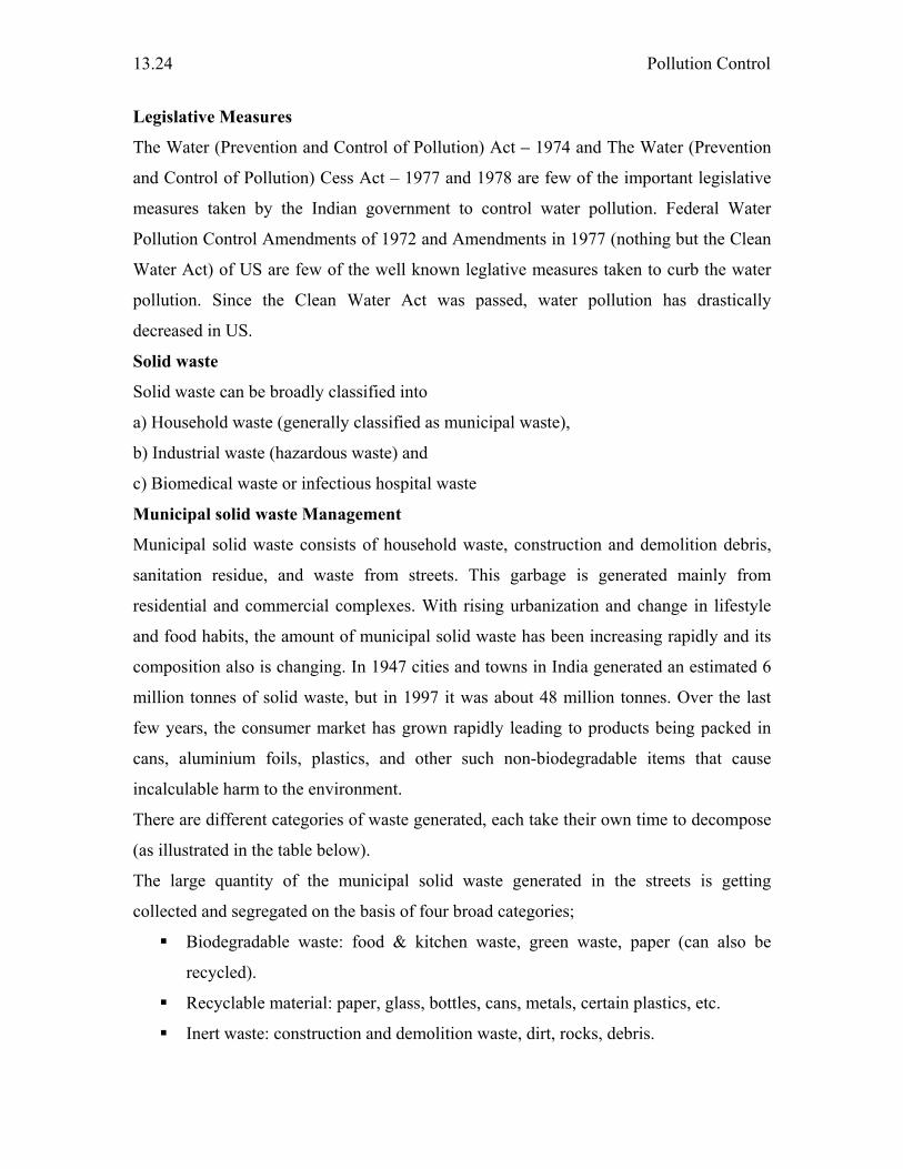
Pollution Control
13.24
Legislative Measures
The Water (Prevention and Control of Pollution) Act – 1974 and The Water (Prevention
and Control of Pollution) Cess Act – 1977 and 1978 are few of the important legislative
measures taken by the Indian government to control water pollution. Federal Water
Pollution Control Amendments of 1972 and Amendments in 1977 (nothing but the Clean
Water Act) of US are few of the well known leglative measures taken to curb the water
pollution. Since the Clean Water Act was passed, water pollution has drastically
decreased in US.
Solid waste
Solid waste can be broadly classified into
a) Household waste (generally classified as municipal waste),
b) Industrial waste (hazardous waste) and
c) Biomedical waste or infectious hospital waste
Municipal solid waste Management
Municipal solid waste consists of household waste, construction and demolition debris,
sanitation residue, and waste from streets. This garbage is generated mainly from
residential and commercial complexes. With rising urbanization and change in lifestyle
and food habits, the amount of municipal solid waste has been increasing rapidly and its
composition also is changing. In 1947 cities and towns in India generated an estimated 6
million tonnes of solid waste, but in 1997 it was about 48 million tonnes. Over the last
few years, the consumer market has grown rapidly leading to products being packed in
cans, aluminium foils, plastics, and other such non-biodegradable items that cause
incalculable harm to the environment.
There are different categories of waste generated, each take their own time to decompose
(as illustrated in the table below).
The large quantity of the municipal solid waste generated in the streets is getting
collected and segregated on the basis of four broad categories;
Biodegradable waste: food & kitchen waste, green waste, paper (can also be
recycled).
Recyclable material: paper, glass, bottles, cans, metals, certain plastics, etc.
Inert waste: construction and demolition waste, dirt, rocks, debris.
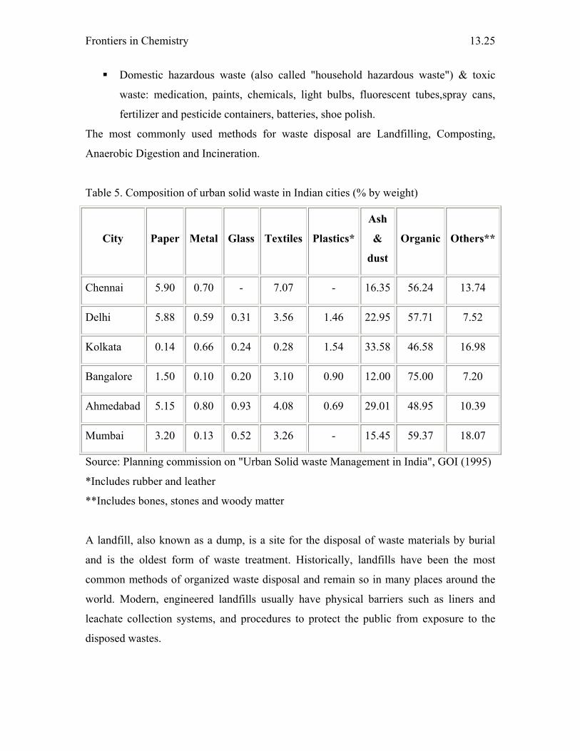
Frontiers in Chemistry
13.25
Domestic hazardous waste (also called "household hazardous waste") & toxic
waste: medication, paints, chemicals, light bulbs, fluorescent tubes,spray cans,
fertilizer and pesticide containers, batteries, shoe polish.
The most commonly used methods for waste disposal are Landfilling, Composting,
Anaerobic Digestion and Incineration.
Table 5. Composition of urban solid waste in Indian cities (% by weight)
City Paper Metal Glass Textiles Plastics*
Ash
&
dust
Organic Others**
Chennai 5.90 0.70 - 7.07 - 16.35 56.24 13.74
Delhi 5.88 0.59 0.31 3.56 1.46 22.95 57.71 7.52
Kolkata 0.14 0.66 0.24 0.28 1.54 33.58 46.58 16.98
Bangalore 1.50 0.10 0.20 3.10 0.90 12.00 75.00 7.20
Ahmedabad 5.15 0.80 0.93 4.08 0.69 29.01 48.95 10.39
Mumbai 3.20 0.13 0.52 3.26 - 15.45 59.37 18.07
Source: Planning commission on "Urban Solid waste Management in India", GOI (1995)
*Includes rubber and leather
**Includes bones, stones and woody matter
A landfill, also known as a dump, is a site for the disposal of waste materials by burial
and is the oldest form of waste treatment. Historically, landfills have been the most
common methods of organized waste disposal and remain so in many places around the
world. Modern, engineered landfills usually have physical barriers such as liners and
leachate collection systems, and procedures to protect the public from exposure to the
disposed wastes.
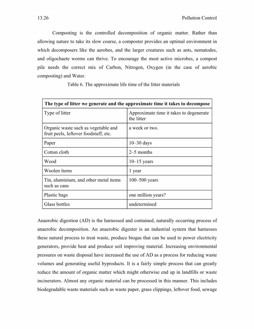
Pollution Control
13.26
Composting is the controlled decomposition of organic matter. Rather than
allowing nature to take its slow course, a composter provides an optimal environment in
which decomposers like the aerobes, and the larger creatures such as ants, nematodes,
and oligochaete worms can thrive. To encourage the most active microbes, a compost
pile needs the correct mix of Carbon, Nitrogen, Oxygen (in the case of aerobic
composting) and Water.
Table 6. The approximate life time of the litter materials
The type of litter we generate and the approximate time it takes to decompose
Type of litter Approximate time it takes to degenerate the litter
Organic waste such as vegetable and fruit peels, leftover foodstuff, etc.
a week or two.
Paper 10–30 days
Cotton cloth 2–5 months
Wood 10–15 years
Woolen items 1 year
Tin, aluminium, and other metal items such as cans
100–500 years
Plastic bags one million years?
Glass bottles undetermined
Anaerobic digestion (AD) is the harnessed and contained, naturally occurring process of
anaerobic decomposition. An anaerobic digester is an industrial system that harnesses
these natural process to treat waste, produce biogas that can be used to power electricity
generators, provide heat and produce soil improving material. Increasing environmental
pressures on waste disposal have increased the use of AD as a process for reducing waste
volumes and generating useful byproducts. It is a fairly simple process that can greatly
reduce the amount of organic matter which might otherwise end up in landfills or waste
incinerators. Almost any organic material can be processed in this manner. This includes
biodegradable waste materials such as waste paper, grass clippings, leftover food, sewage

Frontiers in Chemistry
13.27
and animal waste. Anaerobic digesters can also be fed with specially grown energy crops
to boost biodegradable content and hence increased biogas production. After sorting or
screening to remove inorganic or hazardous materials such as metals and plastics, the
material to be processed is often shredded, minced, or hydrocrushed to increase the
surface area available to microbes in the digesters and hence increase the speed of
digestion. The material is then fed into an airtight digester where the anaerobic treatment
takes place.
Incineration is a waste treatment technology that involves the combustion of
waste at high temperatures. In effect, incineration of waste materials converts the waste
into heat (that can be used to generate electricity), sends gaseous emissions to the
atmosphere, and makes residual ash.
Incineration has particularly strong benefits for the treatment of certain waste types in
niche areas such as clinical wastes and certain hazardous wastes where pathogens and
toxins must be destroyed by high temperatures. Incineration is particularly popular in
countries such as Japan where land is a scarce resource.
Hazardous waste
Many types of businesses generate hazardous waste. Some are small companies that may
be located in a community. For example, dry cleaners, automobile repair shops, hospitals,
exterminators, and photo processing centers all generate hazardous waste. Some
hazardous waste generators are larger companies like chemical manufacturers,
electroplating companies, and oil refineries.
Remarks
Every day, earth becomes more and more polluted. Air pollution fills our lungs with
deadly substances. Water pollution is rapidly eradicating what little freshwater we have
left. Land pollution is causing once-fertile lands to become little more than deserts. And
the earth is choking in the polluted filth produced by humanity. Pollution is gradually
destroying our planet and is gradually killing us too. So it is the need of the hour for
every individual to adapt to sustainable life style and industries to be more concerned
about processes to be sustainable towards our ecosystem.

Pollution Control
13.28
References
1. http://en.wikipedia.org/wiki/Pollution
2. http://www.ndtv.com/pollution/default.asp
3. http://www.cseindia.org/html/lab/health_air.htm
4. http://www.scorecard.org/env-releases/cap/pollutant-desc.tcl
5. http://www.cseindia.org/html/lab/health_air.htm
6. http://www.epa.gov/epaoswer/non-hw/muncpl/facts.htm
7. http://wgbis.ces.iisc.ernet.in/energy/SWMTR/TR85.html
8. Marquita K. Hill, “Understanding Environmental Pollution”, Cambridge University
Press, UK, 2004.
Chapter - 14 CHEMICALS PRODUCTION THROUGH ALTERNATE ROUTES
G. Magesh
1. Introduction
Increasingly, stringent environmental legislation has generated a pressing need for
cleaner methods of chemical production, for instance, technologies that reduce or,
preferably, eliminate the generation of waste and avoid the use of toxic and/or hazardous
reagents and solvents. This trend toward green chemistry necessitates a paradigm shift
from the traditional concept of process efficiency, which focuses exclusively on chemical
yield, to one that assigns economic value to eliminating waste.
One more strategy is to dramatically substitute biochemicals for petrochemicals.
In the last decade technological advances have lowered the cost of producing high quality
products from plant matter while environmental regulations have raised the cost of
manufacturing and using petroleum derived products. One of the examples in this case is
the use of naturally available carbohydrates as raw materials for production of various
chemicals. Attempts are being made to reduce carbon dioxide and naturally available
carbonates to various hydrocarbons or its functionalized derivatives. Carbondioxide is
widely available in atmosphere and its reduction will also reduce global warming since it
is one of the greenhouse gases.
Thus the alternate routes of chemical production can be classified into three broad
categories as (i) routes which utilize alternate sources of energy
(ii) routes which involve alternate processes and technologies
(iii) routes which utilize sources other than petroleum as raw materials for
chemicals
2. Alternate sources of energy
These processes utilize sources other than heat and electricity as the driving force for
carrying out the reactions.
Various technologies involved in this category are
(i) Microwave assisted synthesis
(ii) Sonochemical assisted synthesis
Chemicals Production Through Alternate Routes
14.2
(iii) Light assisted synthesis
2.1. Microwave assisted synthesis
It has long been known that molecules undergo excitation with electromagnetic radiation.
This effect is utilized in household microwave ovens to heat up food. However, chemists
have only been using microwaves as a reaction methodology for a few years. Some of the
first examples gave amazing results, which led to a flood of interest in this novel
technique (1).
The water molecule is the target for microwave ovens in the home; like any other
molecule with a dipole, it absorbs microwave radiation. Microwave radiation is converted
into heat with high efficiency, so that "superheating" becomes possible at ambient
pressure. Enormous accelerations in reaction time can be achieved, if superheating is
performed in closed vessels under high pressure; a reaction that takes several hours under
conventional conditions can be completed over the course of minutes.
2.1.1. Thermal Vs. non thermal effects
Excitation with microwave radiation results in the molecules aligning their dipoles within
the external field. Strong agitation, provided by the reorientation of molecules, in phase
with the electrical field excitation, causes an intense internal heating. The question of
whether a nonthermal process is operating can be answered simply by comparing the
reaction rates between the cases where the reaction is carried out under irradiation versus
under conventional heating. In fact, no nonthermal effect has been found in the majority
of reactions, and the acceleration is attributed to superheating alone. It is clear, though,
that nonthermal effects do play a role in some reactions.
2.1.2. Is a home microwave suitable?
The microwave units specially designed for synthesis are often quite expensive.
Unmodified microwave units suitable for domestic use are suitable in some cases.
However, simple modifications (for example, a reflux condenser) can heighten the safety
factor. High-pressure chemistry should only be carried out in special reactors with a
microwave oven specifically designed for this purpose. A further point in favor of using
more expensive apparatus is the question of reproducibility, since only these specialized
machines can achieve good field homogeneity and in some cases can even be directed on
the reaction vessel.
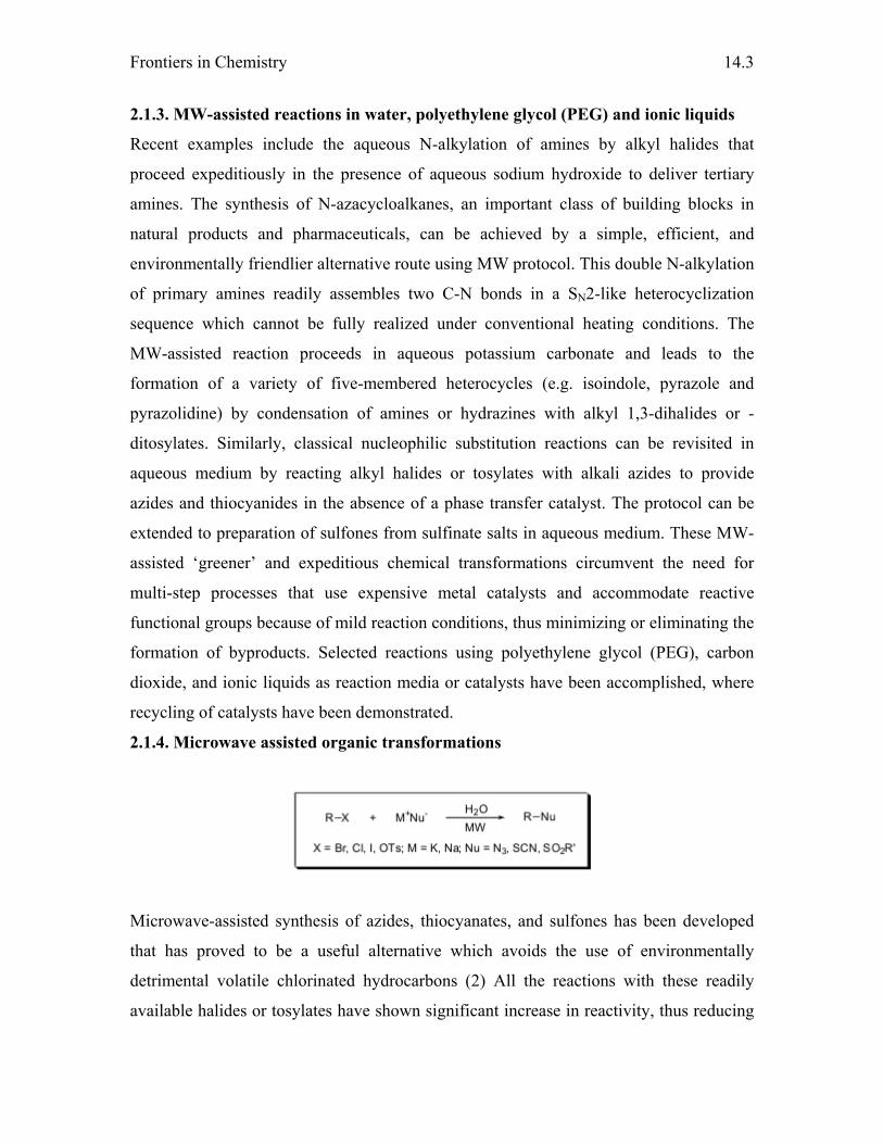
Frontiers in Chemistry
14.3
2.1.3. MW-assisted reactions in water, polyethylene glycol (PEG) and ionic liquids
Recent examples include the aqueous N-alkylation of amines by alkyl halides that
proceed expeditiously in the presence of aqueous sodium hydroxide to deliver tertiary
amines. The synthesis of Ν-azacycloalkanes, an important class of building blocks in
natural products and pharmaceuticals, can be achieved by a simple, efficient, and
environmentally friendlier alternative route using MW protocol. This double N-alkylation
of primary amines readily assembles two C-N bonds in a SN2-like heterocyclization
sequence which cannot be fully realized under conventional heating conditions. The
MW-assisted reaction proceeds in aqueous potassium carbonate and leads to the
formation of a variety of five-membered heterocycles (e.g. isoindole, pyrazole and
pyrazolidine) by condensation of amines or hydrazines with alkyl 1,3-dihalides or -
ditosylates. Similarly, classical nucleophilic substitution reactions can be revisited in
aqueous medium by reacting alkyl halides or tosylates with alkali azides to provide
azides and thiocyanides in the absence of a phase transfer catalyst. The protocol can be
extended to preparation of sulfones from sulfinate salts in aqueous medium. These MW-
assisted ‘greener’ and expeditious chemical transformations circumvent the need for
multi-step processes that use expensive metal catalysts and accommodate reactive
functional groups because of mild reaction conditions, thus minimizing or eliminating the
formation of byproducts. Selected reactions using polyethylene glycol (PEG), carbon
dioxide, and ionic liquids as reaction media or catalysts have been accomplished, where
recycling of catalysts have been demonstrated.
2.1.4. Microwave assisted organic transformations
Microwave-assisted synthesis of azides, thiocyanates, and sulfones has been developed
that has proved to be a useful alternative which avoids the use of environmentally
detrimental volatile chlorinated hydrocarbons (2) All the reactions with these readily
available halides or tosylates have shown significant increase in reactivity, thus reducing
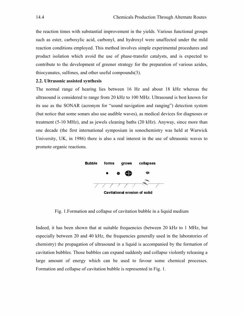
Chemicals Production Through Alternate Routes
14.4
the reaction times with substantial improvement in the yields. Various functional groups
such as ester, carboxylic acid, carbonyl, and hydroxyl were unaffected under the mild
reaction conditions employed. This method involves simple experimental procedures and
product isolation which avoid the use of phase-transfer catalysts, and is expected to
contribute to the development of greener strategy for the preparation of various azides,
thiocyanates, sulfones, and other useful compounds(3).
2.2. Ultrasonic assisted synthesis
The normal range of hearing lies between 16 Hz and about 18 kHz whereas the
ultrasound is considered to range from 20 kHz to 100 MHz. Ultrasound is best known for
its use as the SONAR (acronym for “sound navigation and ranging”) detection system
(but notice that some sonars also use audible waves), as medical devices for diagnoses or
treatment (5-10 MHz), and as jewels cleaning baths (20 kHz). Anyway, since more than
one decade (the first international symposium in sonochemistry was held at Warwick
University, UK, in 1986) there is also a real interest in the use of ultrasonic waves to
promote organic reactions.
Fig. 1.Formation and collapse of cavitation bubble in a liquid medium
Indeed, it has been shown that at suitable frequencies (between 20 kHz to 1 MHz, but
especially between 20 and 40 kHz, the frequencies generally used in the laboratories of
chemistry) the propagation of ultrasound in a liquid is accompanied by the formation of
cavitation bubbles. Those bubbles can expand suddenly and collapse violently releasing a
large amount of energy which can be used to favour some chemical processes.
Formation and collapse of cavitation bubble is represented in Fig. 1.
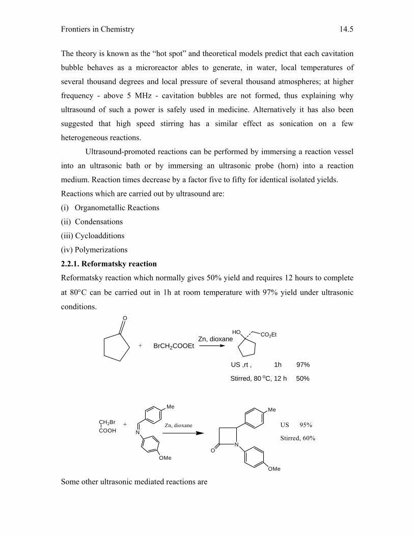
Frontiers in Chemistry
14.5
The theory is known as the “hot spot” and theoretical models predict that each cavitation
bubble behaves as a microreactor ables to generate, in water, local temperatures of
several thousand degrees and local pressure of several thousand atmospheres; at higher
frequency - above 5 MHz - cavitation bubbles are not formed, thus explaining why
ultrasound of such a power is safely used in medicine. Alternatively it has also been
suggested that high speed stirring has a similar effect as sonication on a few
heterogeneous reactions.
Ultrasound-promoted reactions can be performed by immersing a reaction vessel
into an ultrasonic bath or by immersing an ultrasonic probe (horn) into a reaction
medium. Reaction times decrease by a factor five to fifty for identical isolated yields.
Reactions which are carried out by ultrasound are:
(i) Organometallic Reactions
(ii) Condensations
(iii) Cycloadditions
(iv) Polymerizations
2.2.1. Reformatsky reaction
Reformatsky reaction which normally gives 50% yield and requires 12 hours to complete
at 80°C can be carried out in 1h at room temperature with 97% yield under ultrasonic
conditions.
Zn, dioxane
US ,rt , 1h 97%
Stirred, 80 oC, 12 h 50%
O
BrCH2COOEt+
HO CO2Et
CH2BrCOOH N
Me
OMe
Zn, dioxane
N
Me
OMe
O
US 95%
Stirred, 60%
+
Some other ultrasonic mediated reactions are
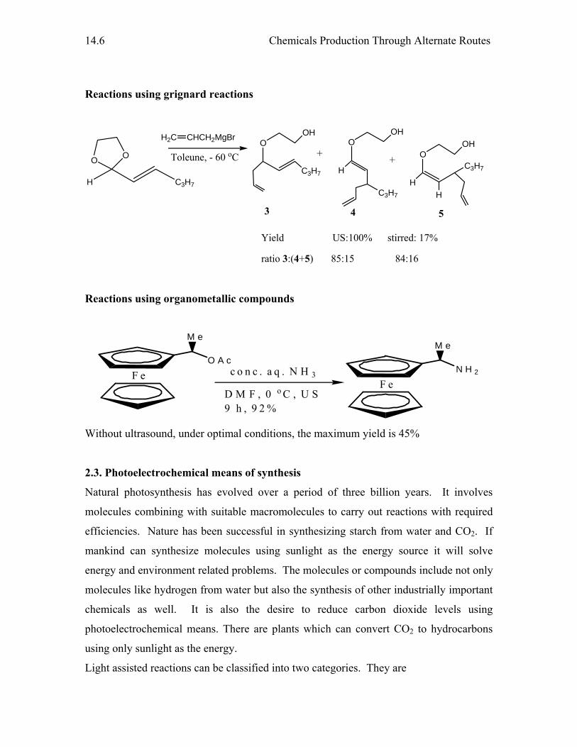
Chemicals Production Through Alternate Routes
14.6
Reactions using grignard reactions
Yield US:100% stirred: 17%
ratio 3:(4+5) 85:15 84:16
H C3H7
OO
H2C CHCH2MgBr
Toleune, - 60 oCO
OHO
H
OH
O
H
OH
C3H7
C3H7 H
C3H7
3 4 5
+ +
Reactions using organometallic compounds
F eO A c
M e
F eN H 2
M e
c o n c . a q . N H 3
D M F , 0 o C , U S9 h , 9 2 %
Without ultrasound, under optimal conditions, the maximum yield is 45%
2.3. Photoelectrochemical means of synthesis
Natural photosynthesis has evolved over a period of three billion years. It involves
molecules combining with suitable macromolecules to carry out reactions with required
efficiencies. Nature has been successful in synthesizing starch from water and CO2. If
mankind can synthesize molecules using sunlight as the energy source it will solve
energy and environment related problems. The molecules or compounds include not only
molecules like hydrogen from water but also the synthesis of other industrially important
chemicals as well. It is also the desire to reduce carbon dioxide levels using
photoelectrochemical means. There are plants which can convert CO2 to hydrocarbons
using only sunlight as the energy.
Light assisted reactions can be classified into two categories. They are
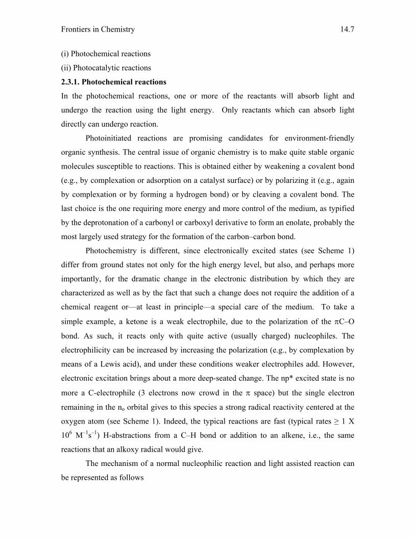
Frontiers in Chemistry
14.7
(i) Photochemical reactions
(ii) Photocatalytic reactions
2.3.1. Photochemical reactions
In the photochemical reactions, one or more of the reactants will absorb light and
undergo the reaction using the light energy. Only reactants which can absorb light
directly can undergo reaction.
Photoinitiated reactions are promising candidates for environment-friendly
organic synthesis. The central issue of organic chemistry is to make quite stable organic
molecules susceptible to reactions. This is obtained either by weakening a covalent bond
(e.g., by complexation or adsorption on a catalyst surface) or by polarizing it (e.g., again
by complexation or by forming a hydrogen bond) or by cleaving a covalent bond. The
last choice is the one requiring more energy and more control of the medium, as typified
by the deprotonation of a carbonyl or carboxyl derivative to form an enolate, probably the
most largely used strategy for the formation of the carbon–carbon bond.
Photochemistry is different, since electronically excited states (see Scheme 1)
differ from ground states not only for the high energy level, but also, and perhaps more
importantly, for the dramatic change in the electronic distribution by which they are
characterized as well as by the fact that such a change does not require the addition of a
chemical reagent or—at least in principle—a special care of the medium. To take a
simple example, a ketone is a weak electrophile, due to the polarization of the πC–O
bond. As such, it reacts only with quite active (usually charged) nucleophiles. The
electrophilicity can be increased by increasing the polarization (e.g., by complexation by
means of a Lewis acid), and under these conditions weaker electrophiles add. However,
electronic excitation brings about a more deep-seated change. The np* excited state is no
more a C-electrophile (3 electrons now crowd in the π space) but the single electron
remaining in the no orbital gives to this species a strong radical reactivity centered at the
oxygen atom (see Scheme 1). Indeed, the typical reactions are fast (typical rates ≥ 1 X
106 M–1s–1) H-abstractions from a C–H bond or addition to an alkene, i.e., the same
reactions that an alkoxy radical would give.
The mechanism of a normal nucleophilic reaction and light assisted reaction can
be represented as follows
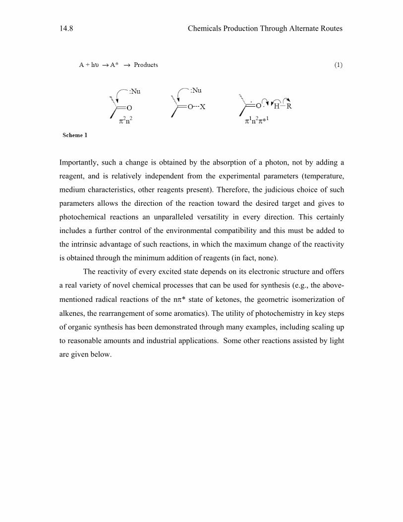
Chemicals Production Through Alternate Routes
14.8
Importantly, such a change is obtained by the absorption of a photon, not by adding a
reagent, and is relatively independent from the experimental parameters (temperature,
medium characteristics, other reagents present). Therefore, the judicious choice of such
parameters allows the direction of the reaction toward the desired target and gives to
photochemical reactions an unparalleled versatility in every direction. This certainly
includes a further control of the environmental compatibility and this must be added to
the intrinsic advantage of such reactions, in which the maximum change of the reactivity
is obtained through the minimum addition of reagents (in fact, none).
The reactivity of every excited state depends on its electronic structure and offers
a real variety of novel chemical processes that can be used for synthesis (e.g., the above-
mentioned radical reactions of the nπ* state of ketones, the geometric isomerization of
alkenes, the rearrangement of some aromatics). The utility of photochemistry in key steps
of organic synthesis has been demonstrated through many examples, including scaling up
to reasonable amounts and industrial applications. Some other reactions assisted by light
are given below.
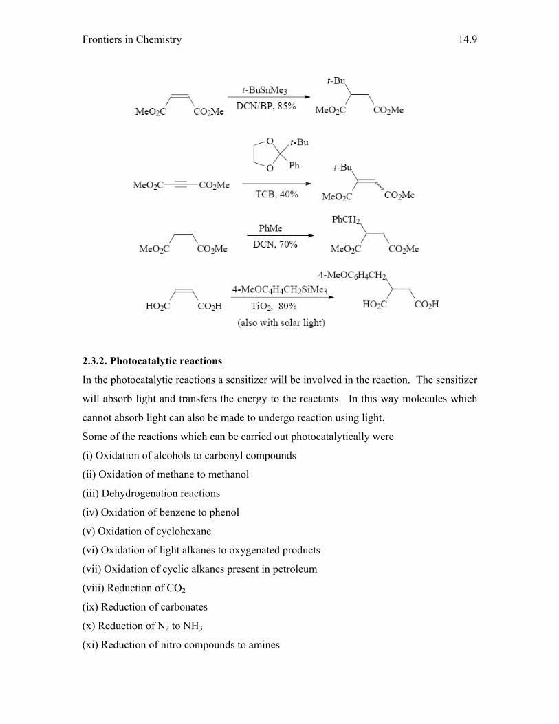
Frontiers in Chemistry
14.9
2.3.2. Photocatalytic reactions
In the photocatalytic reactions a sensitizer will be involved in the reaction. The sensitizer
will absorb light and transfers the energy to the reactants. In this way molecules which
cannot absorb light can also be made to undergo reaction using light.
Some of the reactions which can be carried out photocatalytically were
(i) Oxidation of alcohols to carbonyl compounds
(ii) Oxidation of methane to methanol
(iii) Dehydrogenation reactions
(iv) Oxidation of benzene to phenol
(v) Oxidation of cyclohexane
(vi) Oxidation of light alkanes to oxygenated products
(vii) Oxidation of cyclic alkanes present in petroleum
(viii) Reduction of CO2
(ix) Reduction of carbonates
(x) Reduction of N2 to NH3
(xi) Reduction of nitro compounds to amines

Chemicals Production Through Alternate Routes
14.10
(xii) Hydrogenation reactions
(xiii) Production of hydrogen peroxide
(xiv) Isomerization reactions
(xv) Polymerization reactions
3. Alternate process and technologies
In this case alternate technologies were used both to reduce the waste as well as
improving the efficiency of the reaction.
This category of reactions can be classified as
(i) Catalysis by solid acids and basis
(ii) Bifunctional and multifunctional catalysts
(iii) Asymmetric catalysts
(iv) Biocatalysis (Biotechnology)
(v) Green solvents for organic synthesis
3.1. Catalysis
In chemistry and biology, catalysis is the acceleration (increase in rate) of a chemical
reaction by means of a substance, called a catalyst that is itself not consumed by the
overall reaction. A catalyst provides an alternate route of reaction where the activation
energy is lower than the original chemical reaction. Catalysts participate in reactions but
are neither reactants nor products of the reaction they catalyze. An exception is the
process of autocatalysis where the product of a reaction helps to accelerate the same
reaction. They work by providing an alternative pathway for the reaction to occur, thus
reducing the activation energy and increasing the reaction rate.
3.2. Catalysis by solid acids and bases
3.2.1. Solid acids
Conventional acid catalyzed reactions use acids like H2SO4 whose separation becomes
difficult after the process is complete and thus the process becomes tedious and also
pollutes the environment. Solid acid and base catalysts are appealing since the nature of
acid and basic sites are known and their chemical behavior in acid and base catalyzed
reactions can be rationalized by means of existing theories and models. It is possible to
modify the acidic and basic properties of these materials by adopting various synthesis
and post synthesis routes. In addition, it is possible to confirm these modifications by the
Frontiers in Chemistry
14.11
available techniques. The main task of catalyst technologists is therefore to look for
efficient and stable catalysts which are safe and eco-friendly.
Solid acids which are widely used to carry out organic reactions are
(i) Zeolites
(ii) Mesoporous materials like MCM and SBA
(iii) Alumina
(iv) Silica
(v) Heteropoly acids
(vi) Pillared clays
3.2.2 Base catalysis
Catalysis by solid bases has been less investigated though many interesting examples
involving alkylation and condensation reactions can be found in the literature. The
selective alkylation of catechol to veratrole with dimethyl carbonate has been reported
over K-alumina. Base catalysts (alkali loaded zeolites) have been used in a number of
condensation reactions such as aldol, knoevenagel and Michael condensations.
3.3 Bifunctional and mutilfunctional catalysts
Bifunctional catalysts are those which contain two types of active sites like acid and basic
sites. Bifunctionality can function in a sequential mode or simultaneous mode. In the
simultaneous mode, both the acid and base sites can interact with the substrate in such a
way that the base pushes the electron pair to one part of the substrate, while the acid site
pulls the electron pair from other part of the substrate. This can be classified as concerted
mechanism for which the dehydration of 1-butanol on sodium doped alumina is a typical
example. On the other hand in another variety of simultaneous mode, the acid sites and
basic sites activate the substrates molecules and the activated substrates interact to yield
the desired product. This can be called as go together mechanism and Tishchenko
reaction of benzaldehyde on CaO is an example for this mechanism.
Successive interaction can be conceived in the reformation of
methylcyclopentane (MCP) on silica-alumina and Pt/SiO2 where dehydrogenation and
isomerization occur successively on different sites. This concept of bifunctionality can
have a variety of implications, like enhancement of reaction velocity, improvement in
Chemicals Production Through Alternate Routes
14.12
selectivity and also extending the life of the catalyst. Bifunctionality is often associated
with reforming reactions.
This concept of active sites or bifunctionality has led to the concept of multifunctionality
by which a variety of transformations can be carried out by the same catalytic system and
thus lead to one pot synthesis of the desired products. It can also be possible that the
multifunctionality can lead to many side or unwanted reactions together with the desired
reaction.
3.4. Asymmetric catalysis
Asymmetric catalysis is the phenomenon whereby a chiral catalyst promotes the
conversion of an achiral substrate to a chiral product with a preference for the formation
of one of the mirror image isomers (enantiomers).
The demand for chiral compounds, often as single enantiomers, has escalated
sharply in recent years, driven particularly by the demands of the pharmaceutical
industry, but also by other applications, including agricultural chemicals, flavors,
fragrances, and materials. Two-thirds of prescription drugs are chiral, with the majority of
new chiral drugs being single enantiomers. Although the most obvious applications are
bio-related, materials science also relies on the properties imparted by chirality, notably in
chiral polymers and liquid crystals. This widespread demand for chiral compounds has
stimulated intensive research to develop improved methods for synthesizing such
compounds.
Historically, enantiomerically enriched compounds were generated either by
chemical transformation of an enantiomerically enriched precursor, often derived directly
or indirectly from nature's chiral pool, or by resolving an equimolar (racemic) mixture of
the two enantiomers. Both of these approaches suffer from potentially severe drawbacks,
the former in requiring stoichiometric amounts of a suitable precursor and the latter in
typically yielding only up to 50% of the desired enantiomer.
Asymmetric catalysis, in which each molecule of chiral catalyst, by virtue of
being continually regenerated, can yield many molecules of chiral product, has significant
potential advantages over the older procedures. Indeed, enantiomerically pure compounds
are produced in nature by such chirality transfer from enzymic catalysts. However, it was
only relatively recently that such asymmetric catalysis, with enantiomeric excesses
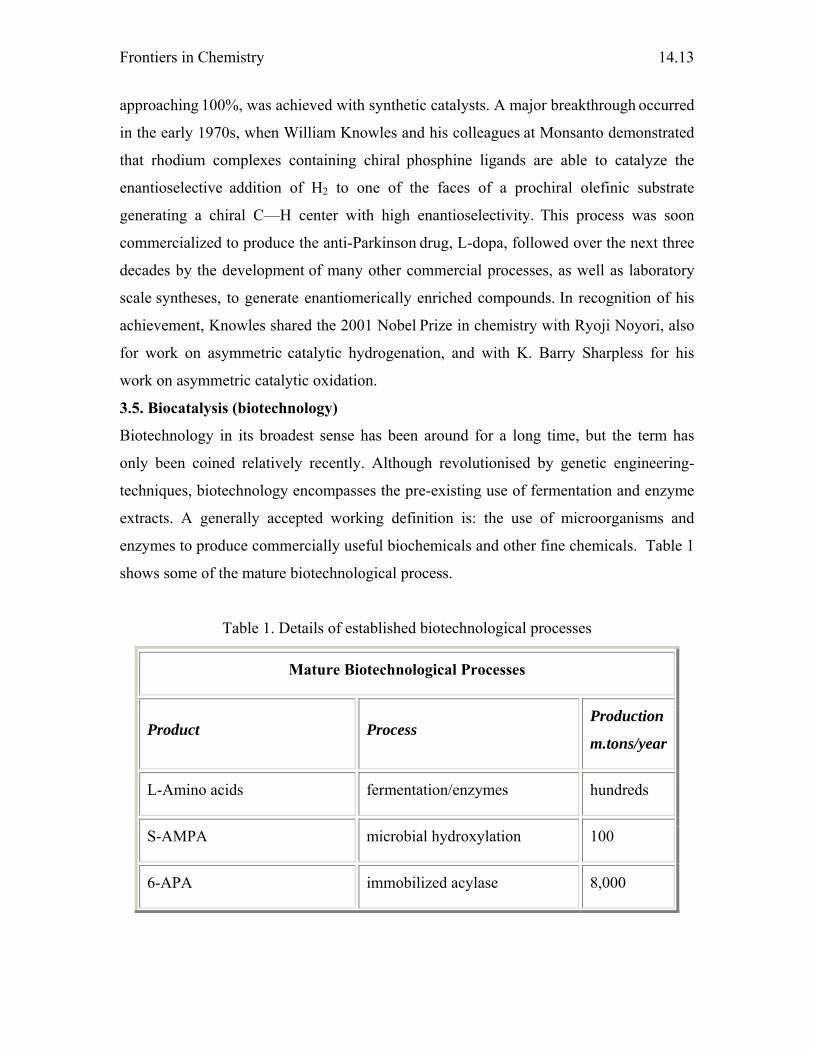
Frontiers in Chemistry
14.13
approaching 100%, was achieved with synthetic catalysts. A major breakthrough occurred
in the early 1970s, when William Knowles and his colleagues at Monsanto demonstrated
that rhodium complexes containing chiral phosphine ligands are able to catalyze the
enantioselective addition of H2 to one of the faces of a prochiral olefinic substrate
generating a chiral C—H center with high enantioselectivity. This process was soon
commercialized to produce the anti-Parkinson drug, L-dopa, followed over the next three
decades by the development of many other commercial processes, as well as laboratory
scale syntheses, to generate enantiomerically enriched compounds. In recognition of his
achievement, Knowles shared the 2001 Nobel Prize in chemistry with Ryoji Noyori, also
for work on asymmetric catalytic hydrogenation, and with K. Barry Sharpless for his
work on asymmetric catalytic oxidation.
3.5. Biocatalysis (biotechnology)
Biotechnology in its broadest sense has been around for a long time, but the term has
only been coined relatively recently. Although revolutionised by genetic engineering-
techniques, biotechnology encompasses the pre-existing use of fermentation and enzyme
extracts. A generally accepted working definition is: the use of microorganisms and
enzymes to produce commercially useful biochemicals and other fine chemicals. Table 1
shows some of the mature biotechnological process.
Table 1. Details of established biotechnological processes
Mature Biotechnological Processes
Product Process Production
m.tons/year
L-Amino acids fermentation/enzymes hundreds
S-AMPA microbial hydroxylation 100
6-APA immobilized acylase 8,000

Chemicals Production Through Alternate Routes
14.14
Aspartame enzymic coupling 750
Cephalosporin C fermentation 3,000
Clavulanic acid fermentation 200
Ergot alkaloids fermentation 25
S-alpha-Chloropropionic acid isolated dehalogenase 1,200
Ephedrine fermentation 500
Erythromycin fermentation 2,000
D-(-)-Hydroxyphenylglycine immobilized enzyme/whole cell 2,750*
17-alpha-Hydroxyprogesterone immobilized hydroxylase 50
Lovastatin fermentation 65
L-Phenylalanine fermentation 8,500
Streptomycin fermentation 1,750
Vitamin B12 fermentation 10
* Also made by chemical resolution (total volume: 3,500 metric tons)
14.3.5.1 The outlook
Biotechnology will continue to mature and new processes will be developed which take
advantage of its benefits. Some older chemical processes will become obsolete and be
replaced by newer technologies, some biotechnical others inspired by biotechnology.
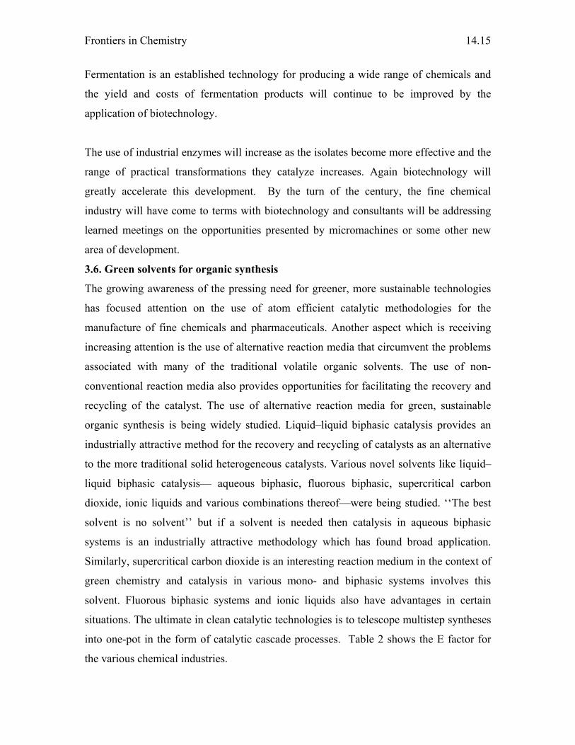
Frontiers in Chemistry
14.15
Fermentation is an established technology for producing a wide range of chemicals and
the yield and costs of fermentation products will continue to be improved by the
application of biotechnology.
The use of industrial enzymes will increase as the isolates become more effective and the
range of practical transformations they catalyze increases. Again biotechnology will
greatly accelerate this development. By the turn of the century, the fine chemical
industry will have come to terms with biotechnology and consultants will be addressing
learned meetings on the opportunities presented by micromachines or some other new
area of development.
3.6. Green solvents for organic synthesis
The growing awareness of the pressing need for greener, more sustainable technologies
has focused attention on the use of atom efficient catalytic methodologies for the
manufacture of fine chemicals and pharmaceuticals. Another aspect which is receiving
increasing attention is the use of alternative reaction media that circumvent the problems
associated with many of the traditional volatile organic solvents. The use of non-
conventional reaction media also provides opportunities for facilitating the recovery and
recycling of the catalyst. The use of alternative reaction media for green, sustainable
organic synthesis is being widely studied. Liquid–liquid biphasic catalysis provides an
industrially attractive method for the recovery and recycling of catalysts as an alternative
to the more traditional solid heterogeneous catalysts. Various novel solvents like liquid–
liquid biphasic catalysis— aqueous biphasic, fluorous biphasic, supercritical carbon
dioxide, ionic liquids and various combinations thereof—were being studied. ‘‘The best
solvent is no solvent’’ but if a solvent is needed then catalysis in aqueous biphasic
systems is an industrially attractive methodology which has found broad application.
Similarly, supercritical carbon dioxide is an interesting reaction medium in the context of
green chemistry and catalysis in various mono- and biphasic systems involves this
solvent. Fluorous biphasic systems and ionic liquids also have advantages in certain
situations. The ultimate in clean catalytic technologies is to telescope multistep syntheses
into one-pot in the form of catalytic cascade processes. Table 2 shows the E factor for
the various chemical industries.
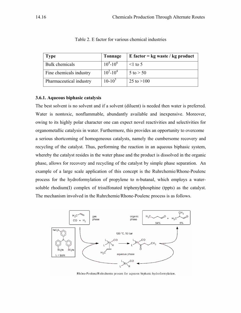
Chemicals Production Through Alternate Routes
14.16
Table 2. E factor for various chemical industries
Type Tonnage E factor = kg waste / kg product
Bulk chemicals 104-106 <1 to 5
Fine chemicals industry 102-104 5 to > 50
Pharmaceutical industry 10-103 25 to >100
3.6.1. Aqueous biphasic catalysis
The best solvent is no solvent and if a solvent (diluent) is needed then water is preferred.
Water is nontoxic, nonflammable, abundantly available and inexpensive. Moreover,
owing to its highly polar character one can expect novel reactivities and selectivities for
organometallic catalysis in water. Furthermore, this provides an opportunity to overcome
a serious shortcoming of homogeneous catalysts, namely the cumbersome recovery and
recycling of the catalyst. Thus, performing the reaction in an aqueous biphasic system,
whereby the catalyst resides in the water phase and the product is dissolved in the organic
phase, allows for recovery and recycling of the catalyst by simple phase separation. An
example of a large scale application of this concept is the Ruhrchemie/Rhone-Poulenc
process for the hydroformylation of propylene to n-butanal, which employs a water-
soluble rhodium(I) complex of trisulfonated triphenylphosphine (tppts) as the catalyst.
The mechanism involved in the Ruhrchemie/Rhone-Poulenc process is as follows.
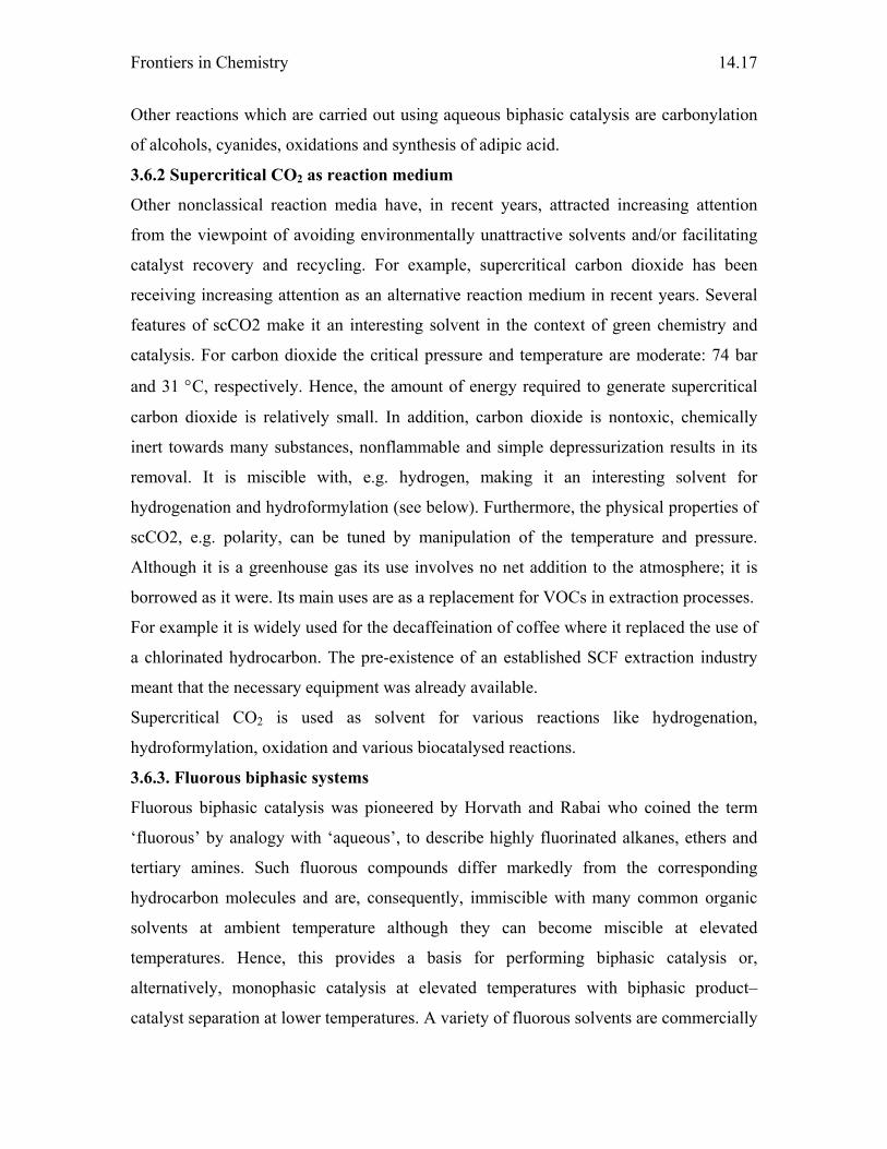
Frontiers in Chemistry
14.17
Other reactions which are carried out using aqueous biphasic catalysis are carbonylation
of alcohols, cyanides, oxidations and synthesis of adipic acid.
3.6.2 Supercritical CO2 as reaction medium
Other nonclassical reaction media have, in recent years, attracted increasing attention
from the viewpoint of avoiding environmentally unattractive solvents and/or facilitating
catalyst recovery and recycling. For example, supercritical carbon dioxide has been
receiving increasing attention as an alternative reaction medium in recent years. Several
features of scCO2 make it an interesting solvent in the context of green chemistry and
catalysis. For carbon dioxide the critical pressure and temperature are moderate: 74 bar
and 31 °C, respectively. Hence, the amount of energy required to generate supercritical
carbon dioxide is relatively small. In addition, carbon dioxide is nontoxic, chemically
inert towards many substances, nonflammable and simple depressurization results in its
removal. It is miscible with, e.g. hydrogen, making it an interesting solvent for
hydrogenation and hydroformylation (see below). Furthermore, the physical properties of
scCO2, e.g. polarity, can be tuned by manipulation of the temperature and pressure.
Although it is a greenhouse gas its use involves no net addition to the atmosphere; it is
borrowed as it were. Its main uses are as a replacement for VOCs in extraction processes.
For example it is widely used for the decaffeination of coffee where it replaced the use of
a chlorinated hydrocarbon. The pre-existence of an established SCF extraction industry
meant that the necessary equipment was already available.
Supercritical CO2 is used as solvent for various reactions like hydrogenation,
hydroformylation, oxidation and various biocatalysed reactions.
3.6.3. Fluorous biphasic systems
Fluorous biphasic catalysis was pioneered by Horvath and Rabai who coined the term
‘fluorous’ by analogy with ‘aqueous’, to describe highly fluorinated alkanes, ethers and
tertiary amines. Such fluorous compounds differ markedly from the corresponding
hydrocarbon molecules and are, consequently, immiscible with many common organic
solvents at ambient temperature although they can become miscible at elevated
temperatures. Hence, this provides a basis for performing biphasic catalysis or,
alternatively, monophasic catalysis at elevated temperatures with biphasic product–
catalyst separation at lower temperatures. A variety of fluorous solvents are commercially
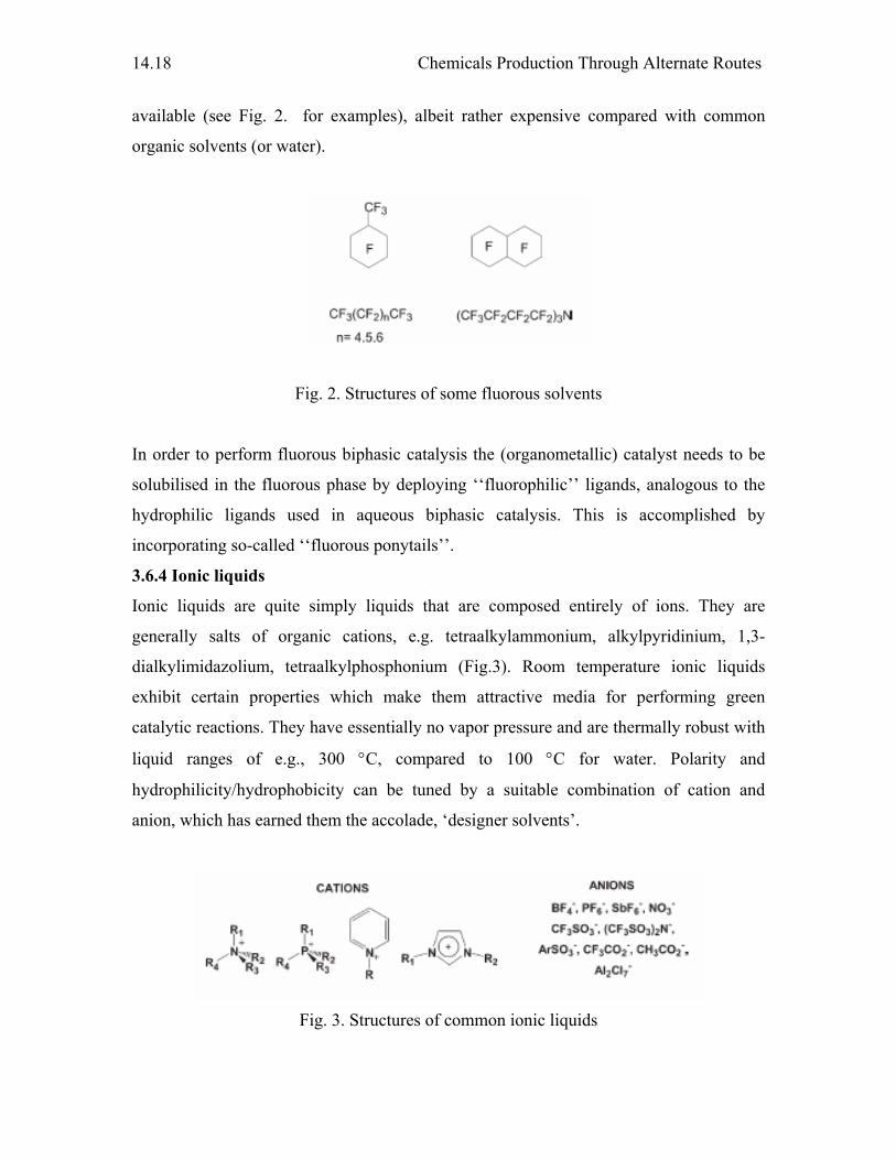
Chemicals Production Through Alternate Routes
14.18
available (see Fig. 2. for examples), albeit rather expensive compared with common
organic solvents (or water).
Fig. 2. Structures of some fluorous solvents
In order to perform fluorous biphasic catalysis the (organometallic) catalyst needs to be
solubilised in the fluorous phase by deploying ‘‘fluorophilic’’ ligands, analogous to the
hydrophilic ligands used in aqueous biphasic catalysis. This is accomplished by
incorporating so-called ‘‘fluorous ponytails’’.
3.6.4 Ionic liquids
Ionic liquids are quite simply liquids that are composed entirely of ions. They are
generally salts of organic cations, e.g. tetraalkylammonium, alkylpyridinium, 1,3-
dialkylimidazolium, tetraalkylphosphonium (Fig.3). Room temperature ionic liquids
exhibit certain properties which make them attractive media for performing green
catalytic reactions. They have essentially no vapor pressure and are thermally robust with
liquid ranges of e.g., 300 °C, compared to 100 °C for water. Polarity and
hydrophilicity/hydrophobicity can be tuned by a suitable combination of cation and
anion, which has earned them the accolade, ‘designer solvents’.
Fig. 3. Structures of common ionic liquids
Frontiers in Chemistry
14.19
Ionic liquids have been extensively studied in the last few years as media for organic
synthesis and catalysis in particular. For example, the hydroformylation of higher olefins,
such as 1-octene, was performed in ionic liquids.
4. Sources other than petroleum as raw materials
4.1. Carbohydrates as feedstock
The search is on for ways to marry the twin goals of economic development and
environmental protection. One of the most promising strategies is to dramatically
substitute biochemicals and other sources for petrochemicals. In the last decade
technological advances have lowered the cost of producing high quality products from
plant matter while environmental regulations have raised the cost of manufacturing and
using petroleum derived products. The rebirth of a biological economy promises not only
environmentally benign industries but a potential renaissance of rural America.
4.1.1. The past
Only a little more than 100 years ago most industrial products were derived from plant
matter or, to a much lesser extent, from animals that fed on plant matter. Clothing was
made from cotton or wool. Adhesives and glues were derived from corn and animal
byproducts like bones and hides. Plant matter was the source of inks, paints, dyes,
pharmaceuticals and most industrial chemicals. We read the word "synthetics" or
"plastics" and immediately assume the product is made from petroleum. But the first
commercial plastic, introduced in the 1880s, was actually made from cotton. Since
cellulosic fibers comprise over 90 percent of cotton, the inventor dubbed the popular
material, celluloid. In the 1920s, car radios were made from wood pulp derived plastics.
The first film plastic is still available and also carries a name derived from its raw
material: cellophane. The first synthetic fiber was cotton based rayon. Rayon is still a
significant commercial fiber.
Today, 65 percent of our clothing is made from oil. Virtually all of our inks,
paints, dyes, pharmaceuticals, plastics, and hundreds of intermediate chemicals are made
from oil. The production of petroleum based plastics alone has expanded by more than
400 percent in the last two decades, to 30 million tons in 1990. Plastics are replacing
glass, metals and paper in an ever expanding variety of products. Petroleum based
Chemicals Production Through Alternate Routes
14.20
products have even entered the food chain, with petrochemical based food dyes and, in
some cases, petroleum derived vinegar.
4.1.2. The present
The biological economy substitutes biochemicals for petrochemicals. In the last decade a
combination of technological advances and environmental regulation has opened up new
markets for industrial products derived from plant matter.
The 20th century has been the age of the hydrocarbon. The 21st century should
witness a rebirth of a carbohydrate economy. Living plants are again becoming attractive
raw materials for manufacturers. The signs may be modest, but the conclusion is
unmistakable. The pendulum is swinging back to a biological economy.
Some plastic bottles now are derived from a plastic manufactured by bacteria
whose food is sugar. The colored ink sections of your local paper will more often than
not contain vegetable oils, not mineral oil. Barbecue fluid may contain grain derived
ethanol. Shampoo may contain vegetable oils and flower fragrances.
4.1.3. The benefits of a biological economy
A biological economy promises environmental and economic benefits. Environmentally,
it benefits us by reducing our reliance on mining minerals and increasing our use of the
stored chemical energy derived from sunlight, water, air and trace minerals in the soil.
Economically, a biological economy benefits us by adding jobs and creating industries in
poorer rural areas.
A biological economy must be based on sustainable cultivation and harvesting
practices. The increased consumption of renewable materials must be matched by an
increased commitment to agricultural techniques that preserve and enhance the quality of
the soil.
Virtually all our non-energy, industrial product needs can be satisfied without
expanding agricultural production. In fact, sufficient agricultural wastes exist to provide
enough raw materials to displace almost all petrochemicals. Substituting biochemicals for
petro-chemicals thus not only substitutes renewable materials for non-renewable
materials but also finds uses for previously discarded materials.

Frontiers in Chemistry
14.21
5. References
1. R.S. Varma “Advances in Green Chemistry: Chemical Syntheses Using Microwave
Irradiation” AstraZeneca Research Foundation India, 2002
2. Yuhong Ju, Dalip Kumar, R. S. Varma, J. Org. Chem., 71 (2006) 6697
3. R.J.J. Jachuck, D.K. Selvaraj R.S. Varma, Green Chem., 8 (2006) 29


![[MS-OFFDI]: Microsoft Office File Format Documentation … · 2017-09-19 · Microsoft Word 97 Microsoft Word 2000 Microsoft Word 2002 Microsoft Office Word 2003 Microsoft Office](https://img.pdfslide.net/doc/110x75/5edde022ad6a402d66691993/ms-offdi-microsoft-office-file-format-documentation-2017-09-19-microsoft-word.jpg)


![[MS-OFFDI]: Microsoft Office File Format Documentation ...MS... · Microsoft PowerPoint 2010 Microsoft PowerPoint 2013 Microsoft Word 97 Microsoft Word 2000 Microsoft Word 2002 Microsoft](https://img.pdfslide.net/doc/110x75/5ea61160271e716b297d501f/ms-offdi-microsoft-office-file-format-documentation-ms-microsoft-powerpoint.jpg)


![Introduction - interoperability.blob.core.windows.netMS-OFFDI]-160914.docx · Web view, by using Microsoft Word 2013, Microsoft Word 2010, Microsoft Office Word 2007, Microsoft](https://img.pdfslide.net/doc/110x75/5d51318488c993b0478b9899/introduction-ms-offdi-160914docx-web-view-by-using-microsoft-word-2013-microsoft.jpg)