Embed Size (px)
Citation preview
SOV29 1968
\
SD 68-723
MISSION EVALUATION PRESIMULATIONREPORT
Part 1: CSM 104 (Mission D)Operations Plan
August 1968
Contract NAS9-150, SA 300, Exhibit I, Paragraph 5. 1. 1. 2
(NASA-CR-129977) MISSION EVALUATIONPBESIHULATION REPORT. PART 1: CSM(MISSION D) OPEBATIONS PLAN (NorthAmerican Rockwell Corp.) Auq. 1968176 p
N73-,70281
Onclas00/99 37204
SPACE DIVISIONNORTH AMERICAN ROCKWELL CORPORATION
SD 68-723
MISSION EVALUATION PRESIMULATIONREPORT
Part 1: CSM 104 (Mission D)Operations Plan
August 1968
Contract NAS9-150, SA 300, Exhibit I, Paragraph 5. 1. 1.2
SPACE DIVISIONNORTH AMERICAN ROCKWELL CORPORATION

SPACE DIVISION OF NORTH AMERICAN ROCKWELL CORPORATION
CONTENTS
Section Page
1.0 INTRODUCTION 1-11.1 Purpose . . . . . . . . . . 1-11 . 2 Mission D G&C Objectives . . . . . . 1 -11 . 3 Simulation Configuration . . . . . . 1 - 21 . 4 Simulation Schedule . . . . . . . 1 - 3
2.0 MISSION DESCRIPTION . . 2-12. 1 Nominal Mission Phases . . . . . . 2-12. 2 Mission Contingency Phases . . . . . 2-5
3.0 STUDY DEFINITION 3-13. 1 Study Phases . 3-13. 2 SPS AV 3-2
3 . 2 . 1 Study Objectives . . . . . . . - • • • 3 - 23 . 2 . 2 Study Scope . . . . . . . . 3 - 33 . 2 . 3 R u n Description . . . . . . . 3 - 33.2 .4 Run Schedule Synopsis . . . . 3-4
3 . 3 Rendezvous . . . . . . . . . 3-483.3. 1 Study Objectives . . . . . . . 3-483. 3. 2 Study Scope 3-483. 3. 3 Run Description . . . . . . . 3-493.3.4 R u n Schedule Synopsis . . . . . 3-50
3.4 Entry 3-763.4.1 Study Objectives 3-763.4. 2 Study Scope 3-763.4.3 R u n Description . . . . . . . 3-773.4.4 R u n Schedule Synopsis . . . . . ' 3-79
3.5 IMU Alignment 3-843. 5. 1 Study Objectives 3-843. 5. 2 Study Scope 3-843.5.3 R u n Description . . . . . . . 3-873. 5.4 Run Schedule Synopsis 3-87
3. 6 Landmark Tracking 3-973 . 6 . 1 Study Objectives . . . . . . . 3-973 . 6 . 2 Study Scope . . . . . . . . 3-973 . 6 . 3 R u n Description . . . . . . . 3-983.6.4 R u n Schedule Synopsis . . . . . 3-98
- 111 -
SD 68-723
SPACE DIVISION OF NORTH AMERICAN ROCKWELL CORPORATION
Section
3.7 SM Abort 3-1053.7.1 Study Objectives 3-1053. 7. 2 Study Scope 3-1053. 7. 3 Run Description . . . . . . 3-1063. 7.4 Run Schedule Synopsis . . . . 3-108
3.8 RCS Deorbit . 3-1133. 8. 1 Study Objectives . . . . . . . 3-1133. 8. 2 Study Scope . . . . . . . 3-1143. 8. 3 Run Description . . . . . . 3-1143.8.4 Run Schedule Synopsis . . . . . 3-118
3. 9 MCC/ME 103 Joint Simulation . . . . . 3-1183.10 Final Software Verification Test . . . . 3-121
4.0 DATA OUTPUT REQUIREMENTS . . . . . 4-14.1 Analog 4-14 . 2 Environment . . . . . . . . . 4 - 14 . 3 Downlink . . . . . . . . . 4 - 1
APPENDIXREFERENCES A-l
- iv -SD 68-723
SPACE DIVISION OF NORTH AMERICAN ROCKWELL CORPORATION
ILLUSTRATIONS
Figure Page
1-1 Simulation Configuration Flow Diagram . . . . . 1-51-2 ME 104 Operations Schedule 1-72-1 Relative Motion of CSM in LM Curvilinear System During
LM Active Rendezvous . . . . . . . . 2-63 - 1 Basic Entry Control Modes . . . . . . . . 3-783-2 SM Abort Philosophy 3-107
- v -
SD 68-723

SPACE DIVISION OF NORTH AMERICAN ROCKWELL CORPORATION
TABLES.
Table Page
2-1 Mission D SPS Burn Summary 2-23-1 ME 104 - GNCS SPS Burn' 3-53-2 ME 104 - SCS ATVC Burn 3-193-3 ME 104 Rendezvous SPS CSI/CDH AV Procedures . . . 3-293-4 LM On SPS AV Run Schedule 3-443 - 5 L M O f f S P S A V R u n Schedule . . . . . . . . 3-463 - 6 M E 1 0 4 Post C D H t o Rendezvous Termination . . . . 3-513-7 LM Active Rendezvous Run Schedule . . . . . . 3 - 7 33-8 CSM Active Rendezvous Run Schedule 3-743-9 Display Panel Switch Position Prior to Entry Run . . . 3-80
3-9A ME 104 Automatic GNCS Entry 3-813-10 Entry Run Schedule 3-853-11 P51 IMU Orientation Procedures . 3-883-12 P52 IMU Realignment 3-893-13 P 5 2 Backup I M U Orientation Determination . . . . 3-923-14 P54 Backup IMU Realignment Program 3-933-15 Alignment Run Schedule 3-963-16 P21 Ground Track Determination 3-993-17 P22 Orbital Navigation 3-1003-18 Orbital Navigation Run Schedule 3-1033-19 Mode IV SPS Abort 3-1093-20 SM Abort Run Schedule Synopsis 3-1123-21 Hybrid RCS Deorbit 3-1143-22 RCS Deorbit Conditions and Rationale 3-1183-23 SM RCS Deorbit Run Schedule. . . . . . . . 3-1193-24 Hybrid RCS Deorbit Run Schedule Synopsis . . . .3 -1204-1 Analog Recording Requirements . . . . . . . 4 - 24-2 Environment Recording Requirements . . . . . 4-44-3 Downlink Data Requirements . . . . . . . . 4 - 1 1
- vn -
SD 68-723

SPACE DIVISION OF NORTH AMERICAN ROCKWELL CORPORATION
1.0 INTRODUCTION
1. 1 PURPOSE
The purpose of the Mission Evaluation 104 Simulation Study is to verifythat the spacecraft guidance, navigation, and control subsystems are capableof performing the planned mission phases under nominal and certain off-nominal conditions. Crew procedures for selected failure mode conditionswill be verified for Mission D. In addition, spacecraft guidance, navigation,and control subsystems performance characteristics will be evaluated forbackup and failure conditions. As a result, a data base will be generatedfor postflight analysis.
The purpose of this report is to define the studies to be accomplishedduring the ME 104 simulation. The flight phases and test objectives ofMission D are identified with simulation study phases. The objectives ofeach simulation study phase are presented as are the detailed run schedules.The performance results of the ME 101 study, Reference 1, stronglyinfluenced the distribution of emphasis on this study.
1.2 MISSION D G&C OBJECTIVES
The Mission D objectives (Reference 2), which are related to theguidance,navigation, and control functions are listed in succeedingparagraphs:
PI. 23 GSM Autopilot Stability Margin (Cannot be satisfied by ME 104)
a. Validate control system stability during short- and long-duration thrusting.
b. Provide a measure of structural dynamic response to aknown forcing function.
PL 24 CSM IMU Alignment Accuracy
a. Evaluate man-machine interfaces during the alignmentprocess.
b. Establish the uncertainties in the alignment process.
c. Evaluate the overall alignment accuracy in a dockedconfiguration
1-1SD 68-723
SPACE DIVISION OF NORTH AMERICAN ROCKWELL CORPORATION
PI. 25 IMU Orientation Determination (Cannot be satisfied in ME 104)
a. Determine if stair patterns are visible in daylight.
b. Obtain data for prediction of star visibility in the lunarlanding mission.
c. Determine if LM surface reflections or mass expulsion aredetrimental to the performance of the IMU orientationdetermination function or midcourse navigation sighting.
PI. 28 GNCS Automatic Entry
a. Verify ability of DAP to control an automatic entry and tomaintain attitude and attitude rates within requireddeadbands.
i
b. Evaluate GNCS accuracy in guiding the CM to a desiredtarget point •without exceeding the allowable g loads.
P20, 33 CSM Single Crewman Rendezvous Capability
a. Obtain data on the single crewman accomplishment ofprocedures and on the operational timeline used in pre-paring the CSM for an active rendezvous and update thesimulation if required.
b. Prepare the CSM for a LM rescue while the LM executesthe phases of the LM concentric flight plan (CFP)rendezvous.
SI. 26 Orbital Navigation/Landmark Tracking
a. Establish error uncertainties in the landmark navigationsightings.
b. Evaluate the procedural aspects of landmark tracking ina flight environment using the SCT.
1.3 SIMULATION CONFIGURATION
The simulation configuration consists of the'following six majorareas:
Analog computersPartial SCS hardware
1-2SD 68-723
SPACE DIVISION OF NORTH AMERICAN ROCKWELL CORPORATION
Partial GNCS hardwareCM evaluatorRTSS/interfaceVisual displays
A total simulation configuration flow diagram is shown in Figure 1-1.A detailed description of each area can be found in Part II of this Pre-simulation Report. This simulation configuration resembles that of ME 101;however, it has the additional capability of providing a visual cue for terminalrendezvous braking employing a LM model.
1. 4 SIMULATION SCHEDULE
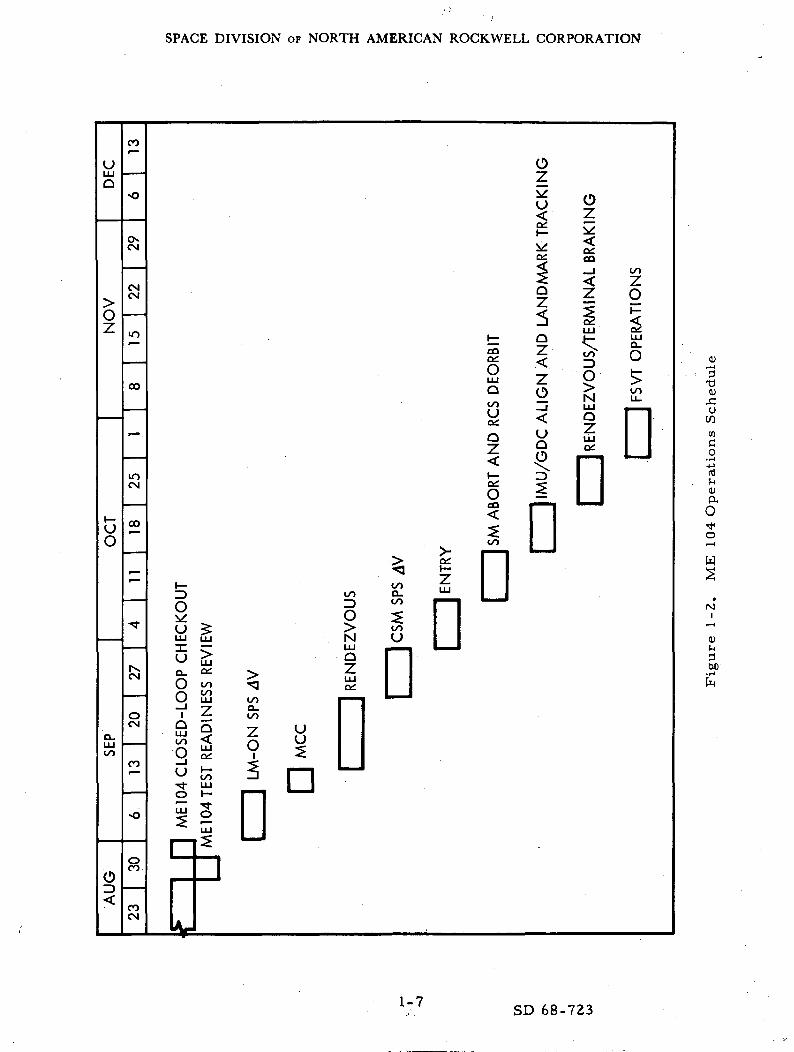
The ME 104 simulation will be conducted in seven study phases des-cribed in detail in Section 3. 0. The preliminary schedule for conductingthese study phases is presented in Figure 1-2 and is based on an estimatedstart date of 2 September 1968. The schedule is for planning purposes only.Past experience has shown that a detailed schedule changes frequentlybecause of unpredictable situations and events.
1-3
SD 68-723

Page Intentionally Left Blank

SPACE DIVISION OF NORTH AMERICAN ROCKWELL CORPORATION
SECTION II VEHICLE DYNAMICS ('ANALOG COMPUTATION)SECTION V SIMULATED SCS ELECTRONICS AND SPS GIMBAL DYNAMICS
PANEL SWITCH POSITIONSVARIABLE SCINERTIASSPS GIMBAL POSITION & ACCEL.
SPS THRUST ON SIGNALATVC G1MB.'CMOS ANGULARACCELERATIONSAND RATESMTVC GIMB. CMOS RCS ENGINE COMMANDS BODY RATES TO
GA2TRANSLATION FORCES
BODY BENDING
TAIL WAG DOG
DOG WAG TAIL
BODY ATT ERRORTO GATXg ACCELERATION
TRANSLATION CMOS
SPS THRUST ON-OFF SPS GIMBAL POSITION
RCS PROPELLANTACCOUNTING SPS AND RCS
THRUST SHAPINGORBITAL PITCH RATE
SECTION VI SCSPROTOTYPE HARDWARE
SECTION VIHCM EVALUATOP
SECTION III RTSS ANDASSOCIATED INTERFACEHARDWARE
EVLER ATT ERRORA/D AND
D/A
CONVERSION
(MODIFIEDFRONT END)
FDAI BALL ANGLE ERRORS IDSKY,
&WINDOW
DISPLAY
FDAI BALL ANGLES
OPTICS MODE CONTROL
SECTION VII SNCS PROTO-TYPE HARDWARE AERO FORCES
AND MOMENTSIMU COARSE ALIGN DRIVE
IMU GIMBAL ANGLES GIMBAL ANGLE I/F
IMU TORQUING I/FVISUAL DISPLAYDRIVE EQNS
SXT & SCTGIMBALDRIVESIMULATOR
IMU & OPTICSANGLE COMMANDS UPLINK/DOWNLINK
AND DOWN/LINK CONTROLIMU S OPTICS ANGLES
SIMULATED FIPA OUTPUTS
PROBLEMINITIALIZATION
GPVS DRIVE SIGNALS
SXT (AND SCT SHAFT AND TRUNNION ANGLES
X-Y COORDINATES FOR SXT IMAGE
DRIVE SIGNALS TO DISPLAY MECHANISMS DIGITAL SHAFT ENCODER'RETURNSSECTION IVEXTERNAL VISUALDISPLAY MECHANISMS
PANEL SWITCH POSITIONS
Figure 1-1. Simulation Configuration Flow Diagram
; 1-5, 1-6SD 68-723
SPACE DIVISION OF NORTH AMERICAN ROCKWELL CORPORATION
uLU
Q
CO
•o
OZ
u 0z
CM
CMCM
oz
00
uo
CM
00
CQ
otou0£
Qi
oCQ<
Qi
OZ
QZ<zo
•G.
D
QiCQ
LU
D
tozoI—<LU
o
D COCO•l-l
•4->(TJJH0)aO
W
to
hsCM
OCM
CO
O^LU LU
o ^O u3
oo
5s
</)
DO
n
u
DD
O8
COCM
1-7 SD 68-723

SPACE DIVISION OF NORTH AMERICAN ROCKWELL CORPORATION
2. 0 MISSION DESCRIPTION
2. 1 NOMINAL MISSION PHASES
The Apollo Mission D is divided into six major periods of activitieswhich are described in detail in Reference 3. The events in each of thesesix periods that will be simulated are discussed in some detail below. TheSPS burn schedule is summarized in Table 2-1. Contingency phases will bediscussed in the next section.
2. 1. 1 First Period of Activities
Prelaunch and launch phases are not simulated.
2.1.1.1 Earth Parking Orbit
Earth parking orbit includes the CSM transposition, docking, and with-drawal of the LM, which will not be evaluated.
2.1.1.2 First Docked SPS Burn
Upon entering darkness, the CSM IMU is realigned, and preparationis made for the first docked SPS ignition. The 63 fps GNCS controlled,external AV targeted burn raises the apogee to 140 nautical miles to ensurean adequate orbital lifetime. This burn also establishes a safe operatingdistance from the S-IVB. A partial demonstration of the CSM digital auto-matic pilot (DAP) attitude control capability is accomplished with this burn.
2 .1 .2 Second Period of Activities
2 . 1 . 2 . 1 Second Docked SPS Burn
This docked SPS burn is the first of two out-of-plane, long-durationburns. The resultant AV of 1200 fps reduces the orbital inclination androtates the line of nodes to the west. About 20, 600 pounds of propellant areconsumed during the 220 seconds of burn, reducing the CSM mass in order toincrease the effectiveness of the CM RCS to perform LM rescue. This burnalso partially demonstrates the CSM DAP attitude control capability duringthe one-half amplitude stroking test accomplished during the burn.
2-1SD 68-723

SPACE DIVISION OF NORTH AMERICAN ROCKWELL CORPORATION
Pu
rpo
se
00
£ £*%' "3 ^t)Z
tp **••
7) OB <» TTfo ^^ i— i U4-» ro H QJO ' — ' .r^ mH £ H •—
flO
• T-i
rttn '
60;rH
rt '0•• - o
1 — 1O tUL, __j
J2 T3
O §U
, — .> to<j ft^ <-M
cO - — -£ "oj ~r
3Q
0)to
C*n O C
.H -H
H 15 gW 4J i,'
O 'g ,£!
•" >s
rti
C .
ffl Z
Pro
vid
es
orb
ital
life
tim
e an
dsa
fe
sep
ara
tio
n f
rom
S-I
VB
be
fore
fir
st S
-IV
B r
esta
rt.
Part
iall
y d
em
on
stra
tes
CS
Mau
top
ilo
t st
ab
ilit
y
ma
rgin
.
o
0•*.i — i
o
T-Itpo0Q
t<WenU2o.^~D00
CMvD
OOoooo
OO,_4
oCMTf
oo
,_,
Re
du
ce
s C
SM
weig
ht
for
LM
resc
ue
or
RC
S d
eo
rbit
.P
art
iall
y d
em
on
stra
tes
CS
Mau
top
ilo
t st
ab
ilit
y m
arg
in.
On
e h
alf
amp
litu
de
stro
kin
gte
st.
•*o
oZH
o
T)0)
A;uop
"xWen .U2Om• — i.
c^c^vO
rslCM
oCMCM
00OO
00O
CMCM
O
CM
Can
cels
tra
jec
tory
eff
ects
o
fb
urn
2.
Re
du
ce
s C
SM
wei
gh
t.
Co
mp
lete
s th
ed
em
on
stra
tio
n o
f C
SM
au
to-
pil
ot
stab
ilit
y m
arg
in.
Fu
llam
pli
tud
e st
rok
ing t
est
.
o
or— 1
O
T)CD
OOQ
•J-J
XwenU2O•*o.a--CT*xDr-H
oorj^
inooi — i
o• — iQs
OO
OOCM
O
OO
Cir
cu
lari
ze
s o
rbit
fo
r re
n-
de
zv
ou
s.
Le
sse
ns
orb
ita
ld
rag
.
•*£
^OO
CO1—1
T.,CD
O0p
"xHenO2'O
•.
COo
f-oa-
o^, — i^oOO
00or— i
^
Ra
ise
s ap
og
ee
to l
ess
en
RC
Sd
eo
rbit
re
qu
ire
me
nts
.
00
P:o
of~l
0
"oCO
C/3o
^wenO2OsOOO
CMOOr^
(-4
i — 1
*£>
(M
oor-H
O
O
in
m
Lo
wer
ap
og
ee
to l
ess
en
RC
Sd
eo
rbit
re
qu
ire
me
nts
.P
osi
tio
ns
pe
rig
ee
to
set
up
de
orb
it c
on
dit
ion
s.
m
o£ •
vO1—1
ooto
C.CU -
"xwenO2O . . .,_,(M.
r«oCT^
vDr-H
•*
O
00
1 — 1om
vO
De
orb
its
CM
. N
om
inal
tou
chd
ow
n a
t -6
0°
lon
git
ud
e.
r-H
CMO
O*"— '
0
"oCO
%enU
4-1
XWeno2Ooor-H
.
vOvOCM
"CM
CM
i — i00
in00
oCM
o^
r-
rtH
2-2
SD 68-723
SPACE DIVISION OF NORTH AMERICAN ROCKWELL CORPORATION
2 .1 .2 .2 Third Docked SPS Burn
Approximately one revolution after the second SPS burn, a 1700 fpsGNCS controlled external AV burn is performed to cancel out the trajectoryeffects of tne second burn. About 12, 000 pounds of propellant are con-sumed during the 186 seconds of burn, further enhancing the CSM1 s capabilityfor LM rescue and SM RCS deorbit. A full-amplitude stroking test isaccomplished during this burn.
2 . 1 . 2 . 3 Fourth Docked SPS Burn
The final docked SPS burn circularizes the orbit at 134 nautical miles.This burn is also GNCS-controlled, and external V targeted to burn9 seconds, providing a 100-fps AV. The resultant circular orbit is the baseorbit from which the LM active rendezvous will be initiated in the fifth period.
2 .1 .3 Third Period of Activities
Not simulated.
2. 1. 3. 1 LM Power-Up and Systems Check
The two LM crew members transfer intravehicle to the LM, wherethey proceed to power up the LM and conduct systems check and evaluation.
2 . 1 . 3 . 2 Docked Descent Propulsion System (DPS) Burn
A 283-second DPS burn is accomplished to verify the GNCS DAPcapability to control rates and attitude during a thrusting maneuver in thedocked configuration and to demonstrate manual throttling of the DPS engine.
2.1.4 Fourth Period of Activities
Not simulated.
2. 1.4. 1 EVA
The primary event is the extra-vehicular transfer of a crew memberfrom the LM to the CSM.
2.1 .5 Fifth Period of Activities
Only CSM activities are simulated. The primary activities within thisperiod are the LM-active "double bubble" rendezvous and an unmanned, long-duration ascent propulsion system (APS) burn. The rendezvous profile begins
2-3
SD 68-723

SPACE DIVISION OF NORTH AMERICAN ROCKWELL CORPORATION
with the LM burning radially up into a-small "football" from which the two
co-elliptic sequence initiation/constant delta height (CSI/CDH) sequencesare set up. The first sequence results in a terminal phase initiation (TPI)from above., •which is not performed, and the second results in a TPI frombelow, which is performed.
The CSM may be required to back up the LM on the above CSI/CDHburns and perform a LM rescue. This will be discussed later inSection 2.2.1.
2 .1 ,6 Sixth Period of Activities
In order to reduce the SM RCS propellant required to deorbit the CMinto the nominal recovery area, two orbit-shaping burns are introduced tolower the perigee and raise the apogee.
2. 1.6. 1 Fifth SPS Burn (Apogee Adjust)
The fifth SPS burn is a. posigrade, CSM-only burn.. The 132-fps,6-second, GNCS-controlled burn raises the apogee from 133 nautical milesto 207 nautical miles.
2. 1.6. 2 Sixth SPS Burn (Perigee Adjust)
The 93-fps, retrograde, GNCS-controlled burn lowers the perigee from131 to 95 nautical miles and adjusts the apogee to 210 nautical miles.
2. 1. 6. 3 Predeorbit Activities
The remainder of the sixth period before deorbit is devoted to accom-plishing navigational sighting objectives, gaining new experience with IMUalignments, and conducting experiments. Only a landmark tracking exercisewill be simulated.
2.1.6.4 Seventh SPS Burn (Deorbit)
The deorbit burn is performed over Hawaii with the CSM pitcheddown 47 degrees in a retrograde position. The external AV, GNCS-controlledburn lasts for 12 seconds to provide a 266 fps AV.
2 .1 .6 .5 Entry
During the 15 minutes of free fall between the deorbit burn and the400, 000-feet entry interface, the CM is separated from the SM and is
2-4
SD 68-723

SPACE DIVISION OF NORTH AMERICAN ROCKWELL CORPORATION
maneuvered to the entry attitude. About 11 minutes later, the CM arrives atthe drogue deployment point, where the simulation is terminated. The GNCS-controiled CM will attain a maximum g peak of 3. 3 before achieving therequired target site.
2.2 MISSION CONTINGENCY PHASES
2. 2. 1 LM Rescue
During the fifth period of activities described above, the CSM must beprepared to back up the LM during the CSI/CDH sequences and perform asubsequent rendezvous. The relative motion of the CSM in the LM-centeredlocal vertical system is shown in Figure 2-1.
In backing up the CSI/CDH burns, the CSM will be targeted (externalAV) to burn 1 minute after the scheduled LM burn. The SPS burn will beopposite in direction to LM burn and about equal in magnitude.
The actual LM rescue could be initiated at three different positions inthe trajectory: TPIg, TPIj, or TPI^.. Prior to TPI, SXT marks will be takenof the LM to update the LM state vector in the GNCS. The TPI burns areSM RCS +X translations or SPS burns depending on the required burn duration.Subsequent to TPI, two midcourse burns maybe required, MCC1 and MCC2.Normally the LM will perform the braking maneuvers to conserve SM RCSpropellant. The CSM will perform the docking maneuver.
2. 2. 2 SM Abort
The SM boost abort phase covers the portion of launch from LESjettison to orbit insertion. Present philosophy for SM boost aborts includesthree abort modes. Mode II is in effect from LES jettison to approximately630 seconds GET and results in impact in the continuous recovery area(CRA). The Mode III abort region begins at Mode II termination and ends atinsertion. Depending on abort conditions, impact occurs in the discreterecovery area (DRA) 3350 nautical miles down-range of the pad or in theIndian Ocean recovery area (IORA). Throughout the Mode III region, capa-bility exists for contingency orbit insertion, which is Mode IV. Therefore,Mode III is least likely to be used, because contingency orbit insertion isprimary when possible. It should be noted that the ME 104 mechanizationdoes not include a simulation of the booster flight phase.
2 . 2 . 3 RCS Deorbit
An RCS deorbit capability should be provided from at least one pointin each orbit as a backup in the event of an SPS failure. The RCS deorbit
2-5
SD 68-723

SPACE DIVISION OF NORTH AMERICAN ROCKWELL CORPORATION
s0>
(ti
-.si
«
•s?a <O i
01>
i(VI
dGO
Q
2-6
SD 67-723

SPACE DIVISION OF NORTH AMERICAN ROCKWELL CORPORATION
maneuver is performed by applying the steady-state thrust generated by theRCS thrusters opposite to the inertial velocity vector, Vp at apogee so as
•to maximize the reduction in perigee altitude per pound of RCS propellantexpended. -
A four-quad SM RCS deorbit is considered to be the nominal backupdeorbit. However, in the event the mission is extended past the SM RCSfour-quad deorbit propellant redline, or a portion of the SM RCS four-quadcapability is lost, a hybrid RCS deorbit using both the SM RCS and CM RCScan be performed. A CM-RCS-only deorbit is not feasible for the "D" mis-sion because the delta V required is not available.
2-7
SD 68-723
SPACE DIVISION OF NORTH AMERICAN ROCKWELL CORPORATION
3.0 STUDY DEFINITION
3. 1 STUDY PHASES
The mission evaluation study will be divided into the following phases:
SPS AVRendezvousEntryIMU/GDC alignmentLandmark trackingSM abortRCS deorbit
In addition, periods of time are allotted for MCC/ME 104 joint simulation andfinal software verification tests (FSVT). The S-IVB/CSM separation and thesubsequent transposition and docking will not be simulated. The study objec-tives and scope and a run schedule synopsis for each study phase are definedin the following paragraphs.
3-1SD 68-723

SPACE DIVISION OF NORTH AMERICAN ROCKWELL CORPORATION
\ '
3.2 SPS AV
3.2.1 Study Objectives
Study objectives are as follows:
1. Evaluate the A V performance, and dynamic characteristics of theCSM/LM-on for the following TVC modes:
CMCMTVC-acceleration
2. Determine the impact of the stroking test on the AV performance.
3. Verify the related CMC programs (P30, P40).
4. Evaluate the AV performance and dynamic characteristics for theCSM solo in the following TVC modes:
CMCAutomatic SCSMTVC-Rate
5. Evaluate the AV performance for the backup AV's during LMrescue.
6. Evaluate the related G&C procedures under nominal and failuretake-over conditions.
7. Determine the pointing accuracy capability of the previouslymentioned TVC modes with and without system errors.
8. Verify that attitude control is maintained or recovered duringan MTVC failure take-over.
9. Determine if a preventive deorbit potential exists for hard-overfailures.
10. Determine the SM RCS propellant required for orientationmaneuvers, propellant settling maneuvers, and damping the SPSshutdown transient.
11. Provide data base for postflight analysis.
3-2SD 68-723

SPACE DIVISION OF NORTH AMERICAN ROCKWELL CORPORATION
3.2 .2 Study Scope
The SPS AV study phase will be divided into two subphases: (1) LM-onSPS burns and (2) CSM-only SPS burns.
3 .2 .2 .1 LM-ON SPS Burns
In this subphase, the AV performance and dynamic characteristicswith the LM-on will be evaluated under nominal, system errors, and failuretake-over conditions. Burns 1 through 4 are included in this category. Thestroking test will be accomplished in Burns 2 and 3. All burns will be GNCS-controlled unless a failure is inserted at which time MTVC Accelerationcommand is initiated. The use of SCS automatic TVC does not seemwarranted with the LM-on and will not be studied.
3 . 2 . 2 . 2 CSM-Only SPS Burns
In this subphase, the AV performance and dynamic characteristics willbe evaluated under nominal, system error, and failure takeover conditions.Burns 5 through 7 are included in this category. These burns will be GNCS-controlled unless a failure is inserted, at which time the MTVC rate com-mand is initiated. In addition, the deorbit burn, Burn 7, will be evaluated inthe SCS automatic TVC mode. Of the scheduled SPS burns, the deorbit burnwill receive the most attention.
In addition, potential CSM-only SPS burns exist during the rendezvousphase. SPS burns may be required to back up the LM at CDHi, CSI.j, and/orCDH2 (Figure 2-1). At this time, only GNCS-controlled burns will be eval-uated, including the effects of system error. Furthermore, no backup topartial LM burns will be considered. The resultant rendezvous after CDHjand CDH2 will then be accomplished in real time. A detailed discussion ofrendezvous is covered in section 3. 3.
3 .2 .3 Run Description
Although in the actual mission each SPS burn is preceded by an IMUalignment, during this study phase all runs will be initiated with a prealignedIMU (ideal REFSMMAT). This reduces run duration; moreover, IMU align-ments are covered in another phase. Based on ME 101 experience, thealignments and subsequent SPS burns will be accomplished during MCC/ME 104 joint simulation and Final Software Verification Test (FSVT).
The detailed sequence of events is taken from the SC 103 AOH(Reference 4). The step-by-step test procedures for CMC and SCS ATVC,
3-3SD 68-723

SPACE DIVISION OF NORTH AMERICAN ROCKWELL CORPORATION
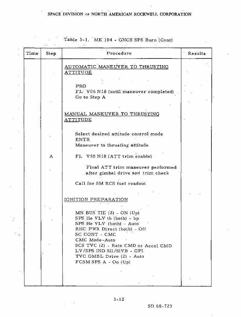
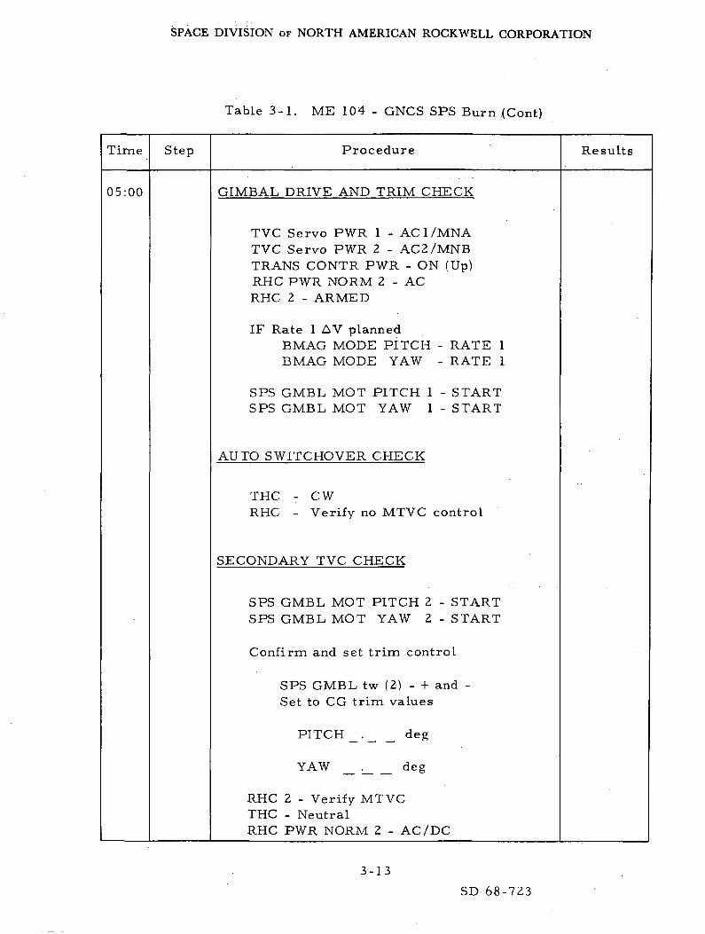
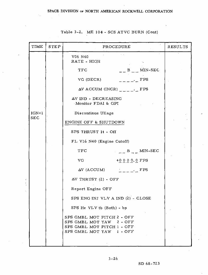
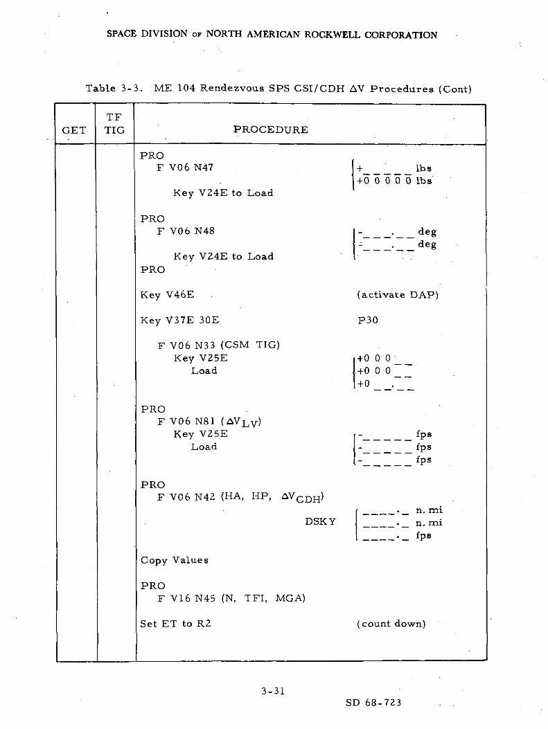
are presented in Tables 3 - l a n d 3-2, respectively. The test procedure forthe backup SPS burns is presented in Table 3-3. It includes both the nonburnoption and required LM update as well as the burn-required option.
3 .2 .4 Run Schedule Synopsis
The run schedule synopsis is divided into the two areas described underScope: LM-on SPS burns (Table 3-4) and CSM-bnly SPS burns (Table 3-5).The proposed runs include the various error sources and/or failures. Theerror sources being considered are thrust misalignment angle (« T)> center-of-gravity uncertainty ( e c. g. , ), and actuator torque load bias (T]_,). Acombined system error (RSS/3(r) value will be obtained using a\^5 <r value fromeach error source. The failure being considered is the SPS gimbal servo-amplifier hard over in either pitch or yaw. The run schedule synopsisincludes the initial conditions, run description, presence of failures, errorsources, and the estimated run lengths.
3-4
SD 68-723

SPACE DIVISION OF NORTH AMERICAN ROCKWELL CORPORATION
Table 3-1. ME 104 - GNCS SPS Burn
Time Step Procedure
Panel 8
All Circuit Breakers IN
B/D Roll (4) OFF
A/C Roll (4) MNA
Pitch (4) MNAYaw (4) MNA
Panel 7
EDS Pwr ON
TVC Servo Pwr 1 AC1/MNATVC Servo Pwr 2 AC2/MNB
FDAI/GPI Pwr BOTH
LOGIC Pwr 2/3 ON
BMAG Power 1 8* 2 ON
SCS Electronics Pwr GDC/ECA
Panel 1
CMC Att IMU
FDAI Scale 5/1
FDAI Select 1/2
FDAI Source CMC
Att Set GDC
Man Att (3) RATE CMD
Limit Cycle OFF
Att Deadband MAX
Rate LOW
Trans Contr Pwr ON
Rot. Contr Pwr Norm (2) AC/DC
Rot. Contr Pwr Direct (2) OFF
SC Cont CMC
Results
3-5
SD 68-723
SPACE DIVISION OF NORTH AMERICAN ROCKWELL CORPORATION
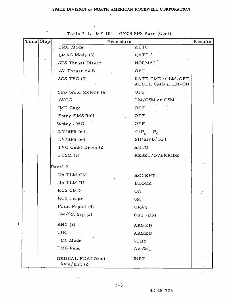
Table 3-1. ME 104 - GNCS SPS Burn (Cont)
Time Step ProcedureCMC Mode AUTO
BMAG Mode (3) . RATE 2
SPS Thrust Direct NORMAL!'
AV Thrust A&B OFF
SCS TVC (2) RATE CMD if LM- OFF,. ACCEL GMD if LM-ON
SPS Gmbl Motors (4) OFF
AVCG LM/CSM or CSM
IMU Cage OFF '.
' Entry EMS Roll OFF
*Entry . 05G OFF
LV/SPS Ind tt/Pc - Pc
LV/SPS Ind . SII/SIVB/GPI
TVC Gmbl Drive (2) AUTO
FCSM (2) RESET /OVERRIDE
Panel 2
Up TLM CM ACCEPT
Up TLM IU BLOCK
RCS CMD ON
RCS Trnpr . . gj^
Prim Prplnt (4) GRAY
CM/SM Sep (2) OFF (DN)
RHC (2) ARMED
THC ARMED
EMS Mode STBY
EMS Func AV SET
ORDEAL FDAI Orbit INRTRate/Inrt (2)
Results
3-6SD 68-723

SPACE DIVISION OF NORTH AMERICAN ROCKWELL CORPORATION
Table 3-1. ME 104 - GNCS SPS Burn (Cont)
Time Step Procedure Results
CMC-ON (required)ISS-ON, orientation known and alignedSCS-ON (required)Orbit change vehicle preparation (desired)
CMC ATT-IMU.05G SW-OFFTest C/W LampsEMS Mode - STBYEMS Func - AV SETSet AV IND toEMS Func - AV
. _ fps
RCS DAP - LOAD AND ACTIVATE (R03)
Key V48E (load DAP)
FL V04 N46 (DAP config)
Rl
R2 .
V24E, load desired dataPRO
FL V06 N47
CSM WT . Ibs
LM WT . I b s
V24E, load desired dataPRO
3-7
SD 68-723

SPACE DIVISION OF NORTH AMERICAN ROCKWELL CORPORATION
Table 3-1. ME 104 - GNCS SPS Burn (Cont)
Time Step Procedure Results
FL V06 N48
PITCH TRIM . deg
YAW TRIM . deg
V24E, load desired dataPRO (exit R03)
Key V46E (activate DAP)
EXT AV PRE-THRUST (P30)
Key V37E 30E
FL V06 N33
GETI, stored 00 . hrs
000 _ _ _ . min
0 _ _.._ _ sec
V25E, load desired dataPRO
FL V06 N81 (AV LCL VRT components)
AVX .._ fps
AVY _ _ _ _._ fps
AVZ ._ fps
V25E, load desired dataPRO
3-8
SD 68-723

SPACE DIVISION OF NORTH AMERICAN ROCKWELL CORPORATION
Table 3-1. ME 104 - GNCS SPS Burn (Cont)
Time Step Procedure Results
FL V06 N42 (calculated thrust parameters)
HA . nm
HP . _ nm
AV (required) _ . _
PRO
FL V16 N45
Marks (VHF optics) _ _ B _ _
TF GETI (nextburn) B
MGA (next burn)
Set event timer to DSKY value
PRO (exit P30)
FL V37
ESTROKER LOAD (IF REQUIRED)
mm-sec
• deg
Key V06 N02EKey 03012ECheck Rl
Accept, PRO
Reject
Key V21 N01EKey 03012E
Key ££££_
PRO
3-9SD 68-723
SPACE DIVISION OF NORTH AMERICAN ROCKWELL CORPORATION
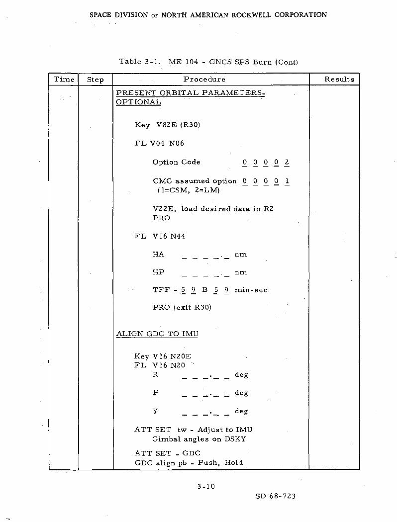
Table 3-1. ME 104 - GNCS SPS Burn (Contl
Time Step Procedure Results
PRESENT ORBITAL PARAMETERS-OPTIONAL
Key V82E (R30)
FL V04 N06
Option Code 0 0 0 0 2
CMC assumed option 0_ 0_ 0_ £ J^(1=CSM, 2=LM)
V22E, load desired data in R2PRO
FL V16 N44
HA
HP
nm
TFF - 1 1 B _5 £ min-sec
PRO (exit R30)
ALIGN GDC TO IMU
Key V16 N20EFL V16 N20 ''
R
P _•_ _ de§
Y . deg
ATT SET tw - Adjust to IMUGimbal angles on DSKY
ATT SET - GDCGDC align pb - Push, Hold
3-10SD 68-723

SPACE DIVISION OF NORTH AMERICAN ROCKWELL CORPORATION
Table 3-1. ME 104 - GNCS SPS Burn (Cont)
Time Step Procedure Results
KEY RELFL V37
G&N THRUSTING (P40)
Key OOEKey V37E 40EKey V06 N81EFL V06 N81
VGX ._ fps
VGY ._ fps
VGZ ._ fps
KEY REL
FL V50 N18 (desired final gimbal angles)
R . deg
P . deg
Y . deg
Call for SM RCS fuel readout
CMC Mode - AutoFDAI/GPI PWR - BothLogic 2/3 PWR - ON (Up)CMC ATT-IMUFDAI SEL - 1/2SCS ELEC PWR - GDC/ECABMAG MODE (3) - Rate 2SC CONT - CMCMAN ATT (3) - Rate CMD
3-11
SD 68-723
SPACE DIVISION OF NORTH AMERICAN ROCKWELL CORPORATION
Table 3-1. ME 104 - GNCS SPS Burn (Cont)
Time Step Procedure Results
AUTOMATIC MANEUVER TO THRUSTINGATTITUDE
PROFL V06 N18 (until'maneuver completed)Go to Step A
MANUAL MANEUVER TO THRUSTINGATTITUDE
Select desired attitude control modeENTRManeuver to thrusting attitude
FL V50 N18 (ATT trim.enable)
Final ATT trim maneuver performedafter gimbal drive and trim check
Call for SM RCS fuel readout
IGNITION PREPARATION
MN BUS TIE (2) - ON (Up)SPS He VLV tb (both) - bpSPS He VLV (both) - AutoRHC PWR Direct (both) - OffSC CONT - CMCCMC Mode-AutoSCS TVC (2) - Rate CMD or Accel CMDLV/SPS IND SII/SIVB - GPITVC GMBL Drive (2) - AutoFCSM SPS A - On (Up)
3-12
SD 68-723
SPACE DIVISION OF NORTH AMERICAN ROCKWELL CORPORATION
Table 3-1. ME 104 . GNCS SPS Burn (Cont)
Time Step Procedure Results
05:00 GIMBAL DRIVE AND TRIM CHECK
TVC Servo PWR 1 - AC 1/MNATVC Servo PWR 2 - AC2/MNBTRANS CONTR PWR - ON (Up)RHC PWR NORM 2 - ACRHC 2 - ARMED
IF Rate 1 AV plannedBMAG MODE PITCH - RATE 1BMAG MODE YAW - RATE 1
SPS GMBL MOT PITCH 1 - STARTSPS GMBL MOT YAW 1 - START
AUTO SWITCHOVER CHECK
THC - CWRHC - Verify no MTVC control
SECONDARY TVC CHECK
SPS GMBL MOT PITCH 2 - STARTSPS GMBL MOT YAW 2 - START
Confirm and set trim control
SPS GMBL tw (2) - + and -Set to CG trim values
PITCH
YAW
deg
deg
RHC 2 - Verify MTVCTHC - NeutralRHC PWR NORM 2 - AC/DC
3-13
SD 68-723

SPACE DIVISION OF NORTH AMERICAN ROCKWELL CORPORATION
Table 3-1. ME 104 - GNCS SPS Burn (Cont)
Time Step Procedure Results
COMPLETE AUTO ATT TRIM
ACCEPT (maneuver)BMAG Mode (3) - RATE - 2Align SC in Roll (ACCEL CMD)SC Cont - CMCPRO
FL V06 N18 (until maneuvercompletion)
R . deg
P • deg
Y . deg
FL V50 N18
.. deg
.. deg
R
P
Y
REJECT (no maneuver)SC CONT - CMCENTR (exit R60)
RHC PWR Direct (both) - MNA/MNBMAN ATT (3) - RATE CMDRATE - HIGHBMAG MODE (3) - ATT 1 RATE 2Call for SM RCS fuel readout
3-14
SD 68-723

SPACE DIVISION OF NORTH AMERICAN ROCKWELL CORPORATION
Table 3-1. ME 104 - GNCS SPS Burn (Cont)
Time Step Procedure Results
02:00
00:35
00:30
00:15
00:05
CMC GMBL DRIVE TEST
FL V50 N25Rl 00204
ACCEPT - PRO (trim at 16 sec)
REJECT - ENTR (trim at 4 sec)
V06 N40
TF GETI
VG
AV (ACCUM)
2 MIN COUNTDOWN,
mm-sec
_ fps
fps
Report TTI = 2 minFDAI SCALE - 5/5AV THRUST A - NORMALTHC - ARMEDRHC (both) - ARMED
DSKY clears
V06 N40(Avg G On)EMS MODE - AUTO
Perform ullage (if required)
FL V99 N40 (engine enable)
3-15
SD 68-723

SPACE DIVISION OF NORTH AMERICAN ROCKWELL CORPORATION
Table 3-1. ME 104 - GNCS SPS Burn.(Cont)
Time
00:00
IGN+ 1SEC
Step Procedure
TF GETI _ _ B _ _ min-sec
VG B _'._ fps
AV (ACCUM) ._ fps
PRO (ENTR inhibits ENG IGN)
IGNITION
SPS THRUST It - ONV06 N40
TFC B min-— — ~~ ~ sec
VG (DECK)' • _ fps
AV ACCUM (INCR) . _ fps
AV IND - DECREASING
Monitor FDAI AND GPI
Discontinue ullage
INITIATE STROKER TEST (IF REQUIRED)
AT TFC = MIN SECKey V68E (initiates stroker test)
Auto termination of stroker test
ENGINE OFF AND SHUTDOWN
SPS THRUST It - Off
Results
3-16
SD 68-723

SPACE DIVISION OF NORTH AMERICAN ROCKWELL CORPORATION
Table 3-1. ME 104 - GNCS SPS Burn (Cont)
Time Step Procedure Results
FL V16 N40 (Engine Cutoff)
TFC B mm- sec
VG _._ fps
AV (ACCUM) _._ fps
AV THRUST A - OFF
Report engine OFF
SPS ENG INJ VLV A IND (2) - CLOSE
SPS He VLV tb (both) - bp
SPS GMBL MOT PITCH 2 - OFFSPS GMBL MOT YAW 2 - OFFSPS GMBL MOT PITCH 1 - OFFSPS GMBL MOT YAW 1 - OFF
SCS TVC SERVO PWR 2 - OFFSCS TVC SERVO PWR 1 - OFFEMS MODE - STBY
Record AV IND __ _ __ _ ._ fps
PRO
FL V16 N85 (VG.vector components)
. VGX ._ fps
VGY ._ fps
VGZ ._ fps
Key V82E
3-17
SD 68-723

SPACE DIVISION OF NORTH AMERICAN ROCKWELL CORPORATION
Table 3-1. ME 104 - GNCS SPS Burn (Cont)
Time Step Procedure Results
FL VI6 N44 (orbital parameters)
HA nm
HP nm
TFF B min-sec
PRO
FL V16 N85
VGX, Y, Z . fps
PROFL V37Key OOE
MN BUS TIE (2) - OFFEMS FUNG - OFFTRANS CONTR PWR - OFFFCSM SPS A - RESET/OVERRIDE
3-18SD 68-723

SPACE DIVISION OF NORTH AMERICAN ROCKWELL CORPORATION
Table 3-2. ME 104 - SCS ATVC BURN
TIME STEP PROCEDURE RESULTS
CMC-ON (Req'd)ISS-ON, Orientation Known & Aligned
SCS-ON (Req'd)Orbit Change Vehicle Preparation (Desired)
CMC ATT-IMU. 05G SW-OFFTest C/W LampsEMS Mode - STBYEMS Func - AV SETSet AV IND to _.. _EMS Func - AVBMAG Mode (3) - ATT 1 RATE 2SC CONT-SCS, SCS TVC (2) - AUTOATT DB - MAX., LIMIT CYCLE - ON
EXT AV PRE-THRUST (P30)
MIN__SECFR INIT TOIGN
MIN SECBURN DUR.
Key V37E 30E
FL V06 N33
GETI, Stored + 00 . HRS
+ °°° __• MIN
+ 0 _ _ . _ _ SEC
V25E, Load Desired DataPRO
FL V06 N81 (AV LCL VRT Components)
AVX . FPS
AVY
AVZ
FPS
FPS
3-19SD 68-723

SPACE DIVISION OF NORTH AMERICAN ROCKWELL CORPORATION
Table 3-2. ME 104 - SCS ATVC BURN (Cont)
TIME STEP PROCEDURE RESULTS
V25E, Load Desired DataPRO
FL V06 N42 (Calc'd Thrust Parameters)
HA . _ N M
HP . _ N M
AV (Req'd) ._FPS
PRO
FL V16 N45
Marks (VHF Optics) B
TF GETI (Next Burn) B MIN-SEC
MGA (Next Burn) . DEC
Set Event Timer to DSKY Value
PRO (Exit P30)
FL V37
PRESENT ORBITALPARAMETERS-OPTIONAL
Key V82E (R30)
FL V04 N06
Option Code 0 0 0 0 2
3-20
SD 68-723

SPACE DIVISION OF NORTH AMERICAN ROCKWELL CORPORATION
Table 3-2. ME 104 - SCS ATVC BURN (Cont)
TIME STEP PROCEDURE RESULTS
CMC As sumed Option 0^ £ 0 0 l_(1=CSM, 2 = LM)
V22E, Load Desired Data in R2PRO
FL VI6 N44
HA
HP
TFF
AT INIT
B MIN-SEC
PRO (Exit R30)
ALIGN GDC TO IMU
Key V16 N20EFL V16 N20
R .
P
DEG
DEG
DEG
ATT SET tw - Adjust to IMUGimbal Angles on DSKY
ATT SET - GDCGDC Align pb - Push, Hold
KEY RELFL V37
3-21SD 68-723

SPACE DIVISION OF NORTH AMERICAN ROCKWELL CORPORATION
Table 3-2. ME 104 - SCS ATVC BURN (Cont)
TIME STEP PROCEDURE RESULTS
GfcN THRUSTING (P40)
Key OOEKey V37E 40EKey V06 N81EFL V06 N81
VGX _.
VGY .
VGZ .
KEY REL
FPS
FPS
FPS
FL V50 N18 (Desired Final Gimbal Angles)
R . DEG
P . DEG
Y . DEG
Call for SM RCS Fuel Readout
CMC Mode - AUTOFDAI/GPI PWR - BOTHLogic 2/3 PWR - ON (Up)CMC ATT-IMUFDAI SEL - 1/2SCS ELEC PWR - GDC/ECASC CONT - SCS
MANUAL MANEUVER TO THRUSTINGATTITUDE
BMAG Mode (3) - RATE 2, MAN ATT(3)ACCEL CMD, LIMIT CYCLE-OFFPROManeuver to Thrusting Attitude
FL V50 N18 (ATT Trim Enable)
3-22SD 68-723

SPACE DIVISION OF NORTH AMERICAN ROCKWELL CORPORATION
Table 3-2. ME 104 - SCS ATVC BURN (Cont)
TIME
05:00
STEP PROCEDURE
Final ATT Trim Maneuver PerformedAfter Gimbal Drive & Trim Check
Call for SM RCS Fuel ReadoutBMAG Mode (3) - ATT 1, RATE 2MAN ATT (3) - RATE CMD, LIMIT
CYCLE-ON
IGNITION PREPARATION
MN BUS TIE (2) - ON (Up)SPS He VLV tb (Both) - bpSPS He VLV (Both) - AUTORHC PWR Direct (Both) - CHSC CONT - SCSCMC Mode- AUTOSCS TVC (2) - AUTOLV/SPS IND SII/SIVB - GPITVC GMBL Drive (2) - AUTOFCSM SPS (2) - ON (UP)
GIMBAL DRIVE AND TRIM CHECK
TVC Servo PWR 1 - ACI/MNATVC Servo PWR 2 - AC2/MNBTRANS CONTR PWR - ON (Up)RHC PWR NORM 2 - ACRHC 2 - ARMED
IF Rate 1 AV PlannedBMAG MODE PITCH - RATE 1BMAG MODE YAW - RATE 1
SPS GMBL MOT PITCH 1 - STARTSPS GMBL MOT YAW 1 - START
AUTO SWITCHOVER CHECK
THC - CWRHC - Verify no MTVC Control
RESULTS
3-23
SD 68-723

SPACE DIVISION OF NORTH AMERICAN ROCKWELL CORPORATION
Table 3-2. ME 104 - SCS ATVC BURN (Cont)
TIME STEP PROCEDURE
SECONDARY TVC CHECK
SPS GMBL MOT PITCH 2 - STARTSPS GMBL MOT YAW 2 - START
Confirm & Set Trim Control
SPS GMBL tw (2) - + and -Set to CG Trim Values
PITCH - _. DEC
YAW - _ - _ _ D E G
RHC 2 - Verify MTVCTHC - NeutralRHC PWR NORM 2 - AC /DC
COMPLETE ATT TRIM
LIMIT CYCLE-OFFB.MAG Mode "(3) - RATE 2, MAN ATT (3) -
MIN IMPRHC 2 — NULL ATT ERRORSATT DB-MINENTR i
RHC PWR Direct (Both) - MNA/MNBMAN ATT (3) - RATE CMD, LIMIT
CYCLE-ONRATE - LOBMAG MODE (3) - ATT 1 RATE 2Call for SM RCS Fuel Readout
CMC GMBL DRIVE TEST
FL V50 N25Rl 00204
ACCEPT - PRO (Trim at 16 SEC)
RESULTS
3-24SD 68-723

SPACE DIVISION OF NORTH AMERICAN ROCKWELL CORPORATION
Table 3-2. ME 104 - SCS ATVC BURN (Cont)
TIME STEP PROCEDURE RESULTS
02:00
00:35
00:30
00:05
00:00
REJECT - ENTR (Trim at 4 SEC)
V06 N40
TF GETI
VG
MIN-SEC
+ ._ FPS
AV (ACCUM) + 0^ 0_ 0^ 0. 0_ FPS
2 MIN COUNTDOWN
Report TTI = 2 MinFDAI SCALE - 5/5AV THRUST (2) - NORMALTHC - ARMEDRHC (Both) - ARMEDLIMIT CYCLE - OFF
DSKY Clears
V06 N40(Avg. G On)EMS MODE - AUTO
Perform Ullage
FL V99 N40 (Engine Enable)
TF GETI B MIN-SEC
VG FPS
AV (ACCUM) . _ FPS
PRO (ENTR Inhibits ENG IGN)
IGNITION
THRUST ON pb PUSHSPS THRUST It - ON
3-25SD 68-723
SPACE DIVISION OF NORTH AMERICAN ROCKWELL CORPORATION
Table 3-2. ME 104 - SCS ATVC BURN (Cont)
TIME
IGN+1SEC
STEP PROCEDURE
V06 N40RATE - HIGH
TFC _ _ B MIN-SEG
VG (DECR) -_FPS
AV ACCUM (INCR) . _ FPS
AV IND - DECREASINGMonitor FDAI & GPI
Discontinue Ullage
ENGINE OFF & SHUTDOWN
SPS THRUST It - Off
FL VI 6 N40 (Engine Cutoff)
TFC B MIN-SEC
VG + Q O Q Q . Q F P S
AV (ACCUM) j ._FPS
AV THRUST (2) - OFF
Report Engine OFF
SPS ENG INJ VLV A IND (2) - CLOSE
SPS He VLV tb (Both) - bp
SPS GMBL MOT PITCH 2 - OFFSPS GMBL MOT YAW 2 - OFFSPS GMBL MOT PITCH 1 - OFFSPS GMBL MOT YAW 1 - OFF
RESULTS
3-26SD 68-723

SPACE DIVISION OF NORTH AMERICAN ROCKWELL CORPORATION
TABLE 3-2. ME 104 - SCS ATVC BURN (Cont)
TIME STEP PROCEDURE
SCS TVC SERVO PWR 2 - OFFSCS TVC SERVO PWR 1 - OFFEMS MODE - STBY
Record AV IND . _ FPS
PRO
FL V16 N85 (VG Vector Components)
VGX . _ FPS
VGY ._ FPS
VGZ ._FPS
Key V82E
FL V16 N44 (Orbital Parameters)
HA ._._ NM
HP -. _ NM
TFF B MIN-SEC
PRO
FL V16 N85VGX, Y, Z . _ FPS
PROFL V37
FCSM SPS (2) - RESET /OVERRIDE
KEY 61E
GO TO G&N CM/SM SEPARATION
RESULTS
3-27SD 68-723

SPACE DIVISION OF NORTH AMERICAN ROCKWELL CORPORATION
Table 3-2. ME 104 - SCS ATVC BURN (Cont)
TIME STEP PROCEDURE RESULTS
ENTRY PARAMETERS (IF RUN ENDS AT ,CM/SM SEPARATION)
FL V06 N6l
IMPACT LAT (+NORTH)IMPACT LONG (+EAST)HDS UP/DN (+UP)
V25E, LOAD DESIRED DATAPRO
DECDEC
FL V06 N60 (ENTRY DATA)
GMAX _ _ _.
V PRED _ _ _ ' _GAMMA El .
PRO
FL V06N63
RTOGO (. 05G TOSPLASH)
VIO (AT . 05G)TFE (TIME FROM
ENTRY)
G. FPS
DEC
B
NM' FPS
MIN-SEC
PRO (EXIT P61)
TERMINATE RUN
3-28
SD 68-723

SPACE DIVISION OF NORTH AMERICAN ROCKWELL CORPORATION
Table 3-3. ME 104 Rendezvous SPS CSI/CDH AV Proceduresa. CSM Backup AV with LM Ignition and Burn
b. CSM Backup AV with No LM Lignition - CSM Performs SPS AV
GETTF
TIG PROCEDURE
Initial Switch Positions
Panel 8All Circuit BreakersB/D Roll Jets (4)A/C Roll Jets (4)Pitch Jets (4)Yaw Jets (4)
Panel 7EDS PwrTVC Servo Pwr 1TVC Servo Pwr 2FDAI/GPI PwrLogic Pwr 2/3BMAG Pwr (both)SCS Elec Pwr
Panel 2UPTLM CMUPTLM IURCS CMDRCS TransferPRIM PRPLNT (4)
Panel 1CMC AttFDAI ScaleFDAI SelectFDAI SourceAtt SetMan Att (3)Limit CycleAtt DBRate
INOFFMNAMNAMNA
ONAC I/MNAAC2/MNBBothON (up)ONGDC/ECA
AcceptBlockONSMGray
IMU5/11/2CMCGDCRate CMDOFFMaxLow
3-29
SD 68-723

SPACE DIVISION OF NORTH AMERICAN ROCKWELL CORPORATION
Table 3-3. ME 104 Rendezvous SPS CSI/CDH AV Procedures (Cont)
GETTFTIG PROCEDURE
Panel 1Trans Contr PwrRHC Pwr - Norm (2)RHC Pwr - Direct (2)SC ControlCMC ModeBMAG Mode (3)SPS Thrust DirectAV Thrust A & BSCS TVC (2)SPS Gimbal Motrs (4)AV CGIMU CageEntry EMS RollEntry . 05GLV/SPS IND - cc/PcLV/SPS IN DSB/SIVB/GPITVC GMBL Drive (2)FCSM (2)CM/SM Sep (2)
Preliminary EMS SetEMS ModeEMS FuncSet AV Ind toEMS Func
Set ET to
Initial Attitude of CSM
Heads UP/DOWNNose (DOWN/UP) Range
Key V37E OOE
*Key V48EF V04 N46
Key V24E to Load
ONAC/DCOFFCMCAutoRate 2NormalOFFRate CMDOFFCSMOFFOFF :OFFPCGPIAutoRe set/Over rideOFF
STBYAV Set
• _ fpsAV
POO
(Load DAP)1110311111
3-30
SD 68-723
SPACE DIVISION OF NORTH AMERICAN ROCKWELL CORPORATION
Table 3-3. ME 104 Rendezvous SPS CSI/CDH AV Procedures (Cont)
GETTFTIG PROCEDURE
PROF V06 N47
Key V24E to Load
PROF V06 N48
Key V24E to LoadPRO
Key V46E
Key V37E 30E
F V06 N33 (CSM TIG)Key V25E
Load
PROF V06 N81 (AVLV)
Key V25ELoad
PROF V06 N42 (HA, HP, AVCDH)
DSKY
Copy Values
PROF VI6 N45 (N, TFI, MGA)
Set ET to R2
+ '_ Ibs+ 0 0 0 0 0 I b s
degdeg
(activate DAP)
P30
+ 0 0 0+ 0 0 0 "+0
fpsfpsfps
n. min, mifps
(count down)
3-31SD 68-723

SPACE DIVISION OF NORTH AMERICAN ROCKWELL CORPORATION
Table 3-3. ME 104 Rendezvous SPS CSI/CDH AV Procedures (Cont)
GETTFTIG PROCEDURE
PROF V37
Key OOE
CB EMS (2)EMS ModeEMS Func.EMS ModeLoad AVEMS Func
Monitor SPS It.Monitor AVMonitor SPS It.
Confirm AVEMS ModeEMS FuncLoad AVEMS Func '
Key V82EF V04 N06 (code, option)
00002OOOOx
(1 = CSM, 2 = LM)Accept or Load
PROF V16 N44 (HA, HP, TFF)
POO
- Closed- STBY- AV Set- Auto= 1586.8 fps- AV Test- ONCountdown- OFF= -20 .8 ± 20 .7- STBY- AV Set
- AV
(ORB. PARAM. )
00001
DSKYn. min. mim/s
PRO
Align GDC to IMUKey V16 N20 E
F V16 N20 (R, P, Y)
3-32SD 68-723
SPACE DIVISION OF NORTH AMERICAN ROCKWELL CORPORATION
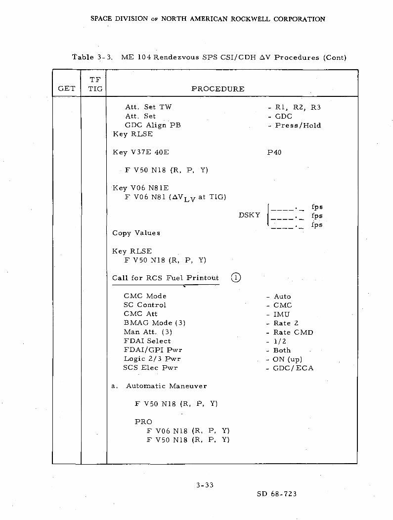
table 3-3. ME 104 Rendezvous SPS CSI/CDH AV Procedures (Cont)
GETTFTIG PROCEDURE
Att. Set TWAtt. SetGDC Align PB
Key RLSE
Key V37E 40E
F V50 N18 (R, P, Y)
Key V06 N81EF V06 N81 (AVLV at TIG)
Copy Values
Key RLSEF V50 N18 (R, P, Y)
Call for RCS Fuel Printout I
CMC ModeSC ControlCMC AttBMAG Mode (3)Man Att. (3)FDAI SelectFDAI/GPI PwrLogic 2/3 PwrSCS Elec Pwr
a. Automatic Maneuver
F V50 N18 (R, P, Y)
PROF V06 N18 (R, P, Y)F V50 N18 (R, P, Y)
- Rl, R2, R3- GDC- Press/Hold
P40
DSKY._ fps. __ fps._ fps
- Auto- CMC- IMU- Rate 2- Rate CMD- 1/2- Both- ON (up)- GDC/EGA
3-33SD 68-723

SPACE DIVISION OF NORTH AMERICAN ROCKWELL CORPORATION
Table 3-3. ME 104 Rendezvous SPS CSI/CDH AV Procedures (Cont)
GETTFTIG PROCEDURE
PROF V06 N18F V50 N18
b. Manual Maneuver
F V50 N18 (R, P, Y)
SC ControlMan. Att.PRORHCMan Att.
c. Trim Maneuver
F V50 N18 (R, P, Y)
SC ControlCMC ModePRO
F V06 N18F V50 N18
Final Trim After Tests
Call for Fuel Printout^
Ignition Preparation
MN Bus Tie (2)SPS He VLV tb (Both)SPS He VLV (Both)RHC Pwr Direct (Both)SC ControlCMC ModeSCS TVC (2)LV/SPS IND SII/SIVB
(to trim)
SCSAccel. CMD
maneuver to Att.Rate CMD
CMCAuto
- ON (up)- Bp- Auto- OFF- CMC- Auto- Rate CMD- GP1
3-34
SD 68-723
SPACE DIVISION OF NORTH AMERICAN ROCKWELL CORPORATION
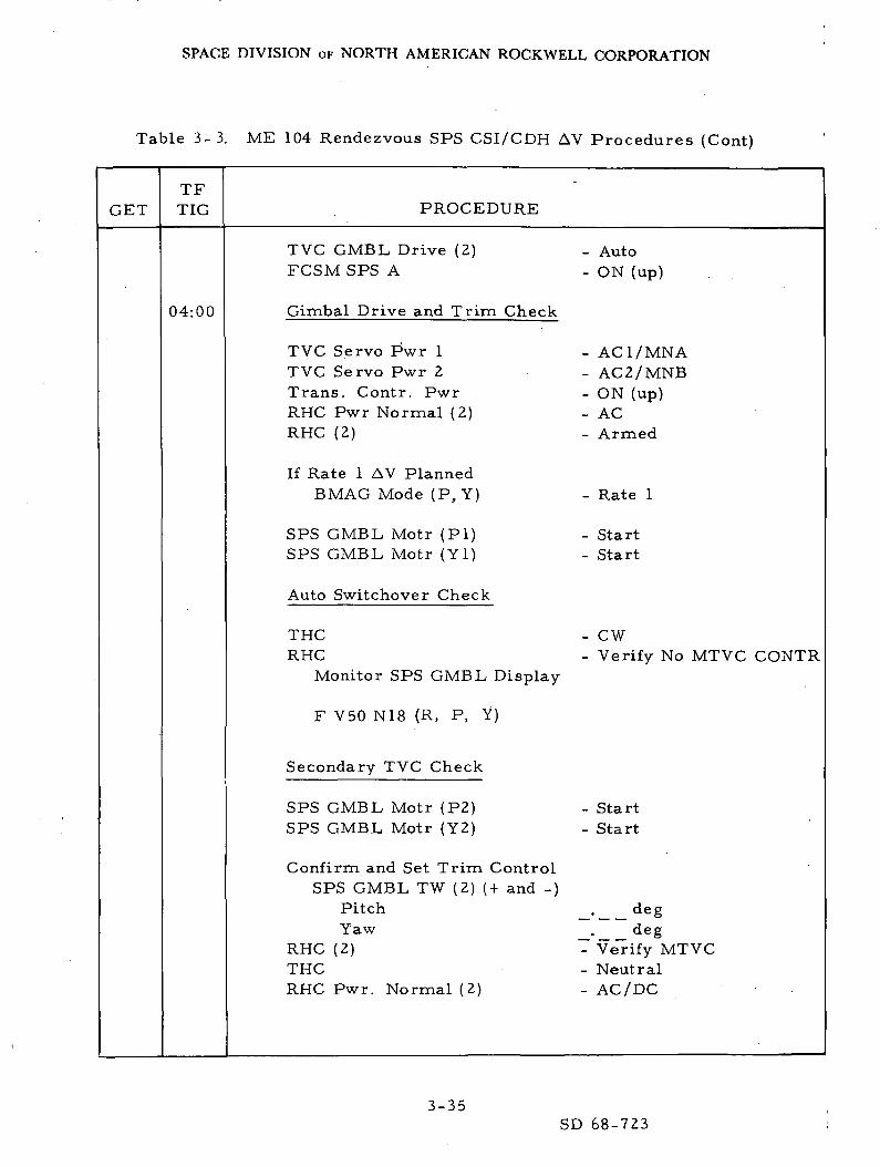
Table 3-3. ME 104 Rendezvous SPS CSI/CDH AV Procedures (Cont)
GETTFTIG PROCEDURE
04:00
TVC GMBL Drive (2)FCSM SPS A
Gimbal Drive and Trim Check
TVC Servo P'wr 1TVC Servo Pwr 2Trans. Contr. PwrRHC Pwr Normal (2)RHC (2)
If Rate 1 AV PlannedBMAG Mode (P, Y)
SPS GMBL Motr ( P I )SPS GMBL Motr ( Y l )
Auto Switchover Check
THCRHC
Monitor SPS GMBL, Display
F V50 N18 (R, P, Y)
Secondary TVC Check
SPS GMBL Motr (P2)SPS GMBL Motr (Y2)
Confirm and Set Trim ControlSPS GMBL TW (2) (+ and -)
PitchYaw
RHC (2)THCRHC Pwr. Normal (2)
AutoON (up)
AC1/MNAAC2/MNBON (up)ACArmed
- Rate 1
- Start- Start
- CW- Verify No MTVC CONTR
StartStart
. deg
. degVerify MTVCNeutralAC/DC
3-35SD 68-723
SPACE DIVISION OF NORTH AMERICAN ROCKWELL CORPORATION
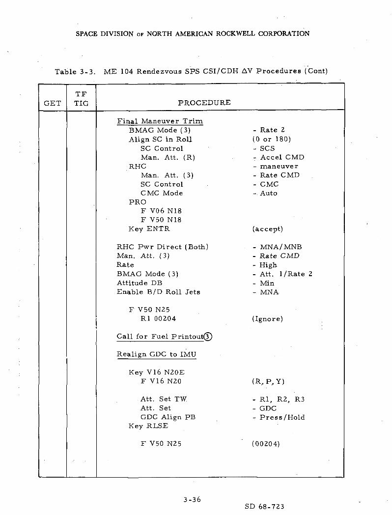
Table 3-3. ME 104 Rendezvous SPS CSI/CDH AV Procedures (Cont)
GETTFTIG PROCEDURE
Final Maneuver TrimBMAG Mode (3)Align SC in Roll
SC ControlMan. Att. (R)
RHCMan. Att. (3)SC ControlCMC Mode
PROF V06 N18F V50 N18
Key ENTR
RHC Pwr Direct (Both)Man. Att. (3)RateBMAG Mode (3)Attitude DBEnable B/D Roll Jets
F V50 N25Rl 00204
Call for Fuel Printout^
Realign GDC to IMU
Key V16 N20EF V16 N20
Att. Set TWAtt. SetGDC Align PB
Key RLSE
F V50 N25
- Rate 2(0 or 180)- SCS- Accel CMD- maneuver- Rate CMD- CMC- Auto
(accept)
- MNA/MNB- Rate CMD- High- Att. I/Rate 2- Min- MNA
(Ignore)
(R,P,Y)
- Rl, R2, R3- GDC- Press/Hold
(00204)
3-36SD 68-723
SPACE DIVISION OF NORTH AMERICAN ROCKWELL CORPORATION
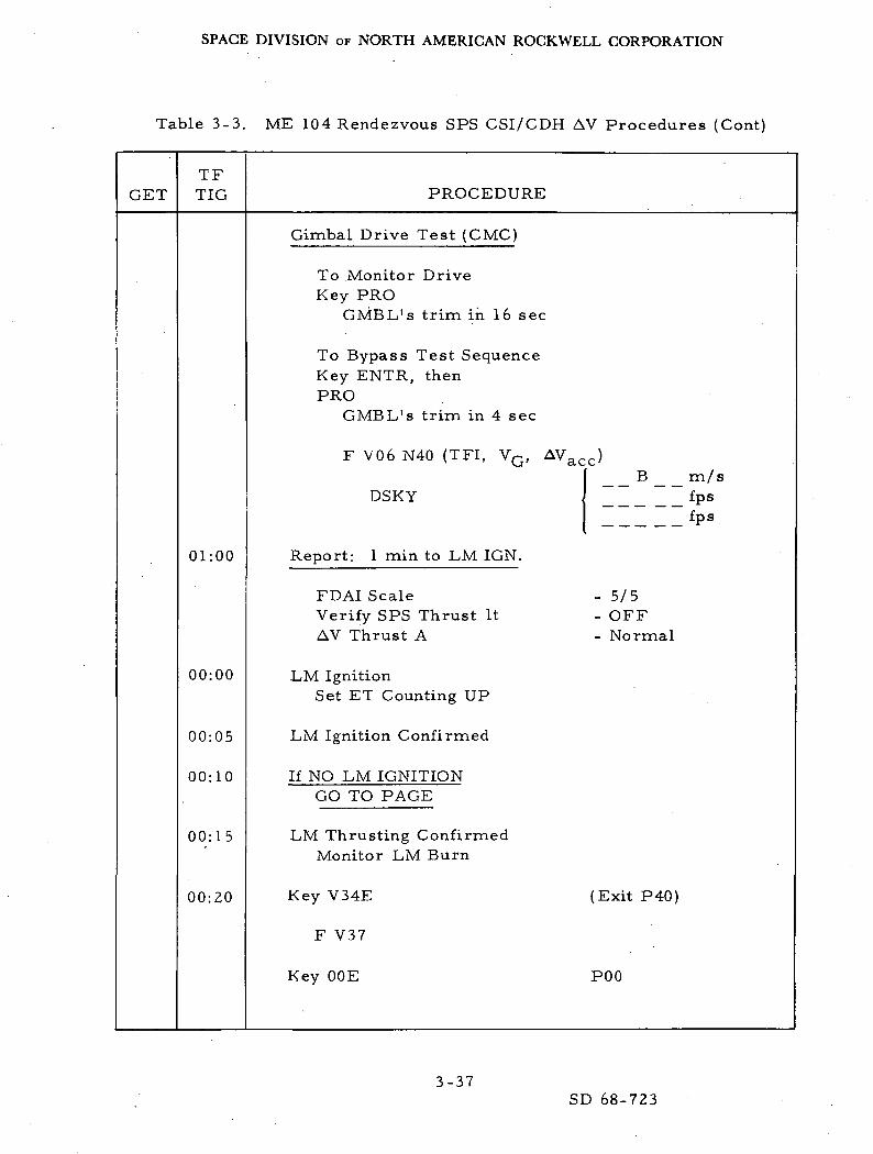
Table 3-3. ME 104 Rendezvous SPS CSI/CDH AV Procedures (Cont)
TFGET TIG
01:00
00:00
00:05
00:10
00:15
00:20
PROCEDURE
Gimbal Drive Test (CMC)
To Monitor DriveKey PRO
GMBL's trim in 16 sec
To Bypass Test SequenceKey ENTR, thenPRO
GMBL's trim in 4 sec
F V06 N40 (TFI, VG, AVacc)
DSKY
Report: 1 min to LM IGN.
FDAI ScaleVerify SPS Thrust ItAV Thrust A
LM IgnitionSet ET Counting UP
LM Ignition Confirmed
If NO LM IGNITIONGO TO PAGE
LM Thrusting ConfirmedMonitor LM Burn
Key V34E
F V37
Key OOE
B m/sfpsfps
- 5/5- OFF- Normal
(Exit P40)
POO
3-37SD 68-723
SPACE DIVISION OF NORTH AMERICAN ROCKWELL CORPORATION
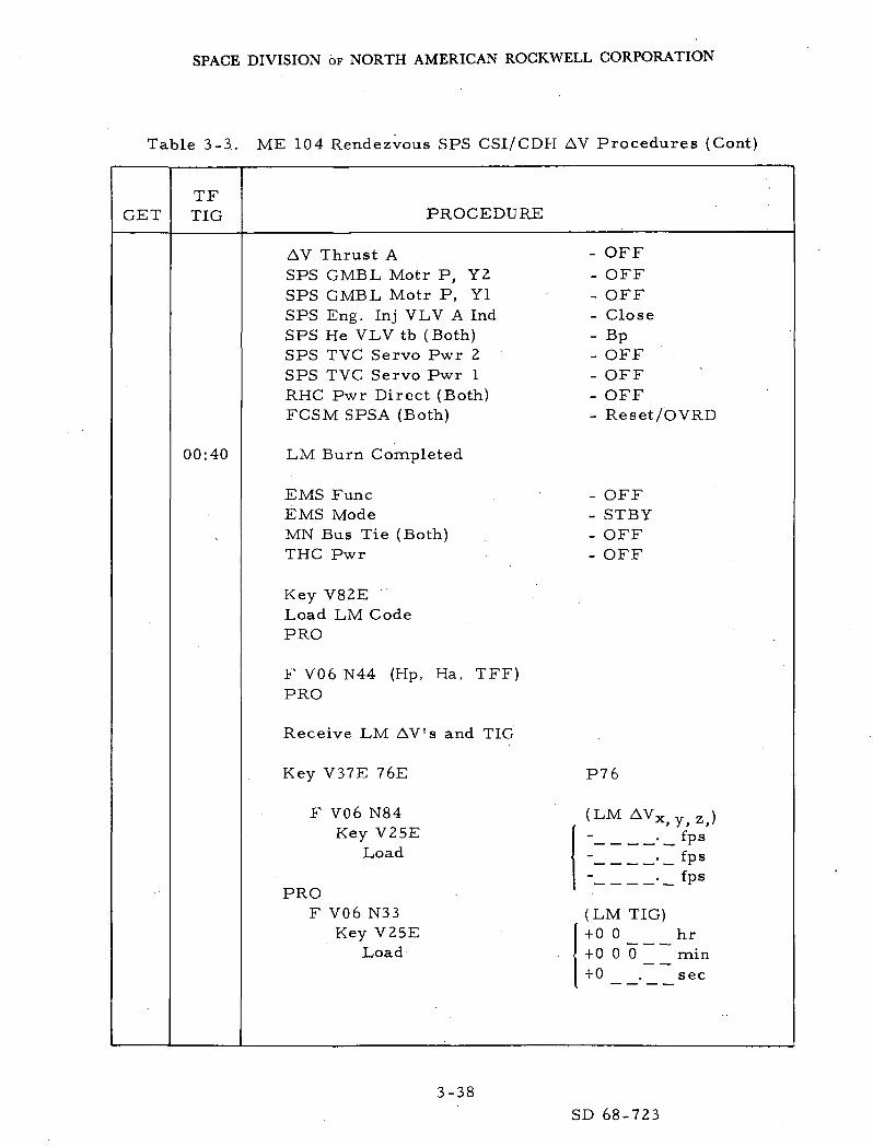
Table 3-3. ME 104 Rendezvous SPS CSI/CDH AV Procedures (Cont)
GETTFTIG
00:40
PROCEDURE
AV Thrust A - OFFSPS GMBL Motr P, Y2 - OFFSPS GMBL Motr P, Yl - OFFSPS Eng. Inj VLV A Ind - CloseSPS He VLV tb (Both) - BpSPS TVC Servo Pwr 2 - OFFSPS TVC Servo Pwr 1 - OFFRHC Pwr Direct (Both) - OFFFCSM SPSA (Both) - Reset/OVRD
LM Burn Completed
EMS Func - OFFEMS Mode - STBYMN Bus Tie (Both) - OFFTHC Pwr - OFF
Key V82ELoad LM CodePRO
F V06 N44 (Hp, Ha, TFF)PRO
Receive LM AV's and TIG
Key V37E 76E P76
F V06 N84 (LM AVX y z )Key V25E - • 1 f V
Load - . fpsfps
PROF V06 N33 (LM TIG)
Key V25E +0 0 __ hrLoad + 0 0 0 min
+0 . sec
3-38
SD 68-723

SPACE DIVISION OF NORTH AMERICAN ROCKWELL CORPORATION
Table 3-3. ME 104 Rendezvous SPS CSI/CDH AV Procedures (Cont)
TFGET TIG
Step A
PROCEDURE
PROF V37
Key OOEKey V82E
Load LM code
PROF V06 N44 (Hp, Ha, TFF)
PRO
a. If TPI to be completed
Key V37E 20E
Continue: Use RendezvousProcedures
b. If TPI Computations Only
Key V37E 34E
F V06 N37 (TIG TPI)Key V25E
Load
PROF V06 N55
Key V22ELoad E
Key V23 ELoad <r
PROF VI 6 N45 (N, TFI, MGA)
POO
P20
P34
+ 0 0 hr+ 000 min+0 . sec
( - , E , <r )
- . deg
= . deg
3-39SD 68-723

SPACE DIVISION OF NORTH AMERICAN ROCKWELL CORPORATION
Table 3-3. ME 104 Rendezvous SPS CSI/CDH AV Procedures (Cont)
GETTFTIG PROCEDURE
DO NOT PROCEED
Key V32E (Recycle)
F V06 N37 (TIG/TPI)+ 00 hr
(DSKY) + 0 0 0 _ _ m i n+0 . sec
Copy Values
PROF V06 N58 (Hp, AVTpI, AVTpF)
._ n. miDSKY - _ f p s
- _ f p s
Copy Values
PROF V06 N59 (AV^QS comp. )
fpsDSKY ._ fps
._ fps
Copy Values
PROF V 1 6 N 4 5 (N, TFI, MGA);
Key V34E (terminate prog. )
F V37
Key OOE PQO
TERMINATE RUN
3-40SD 68-723
SPACE DIVISION OF NORTH AMERICAN ROCKWELL CORPORATION
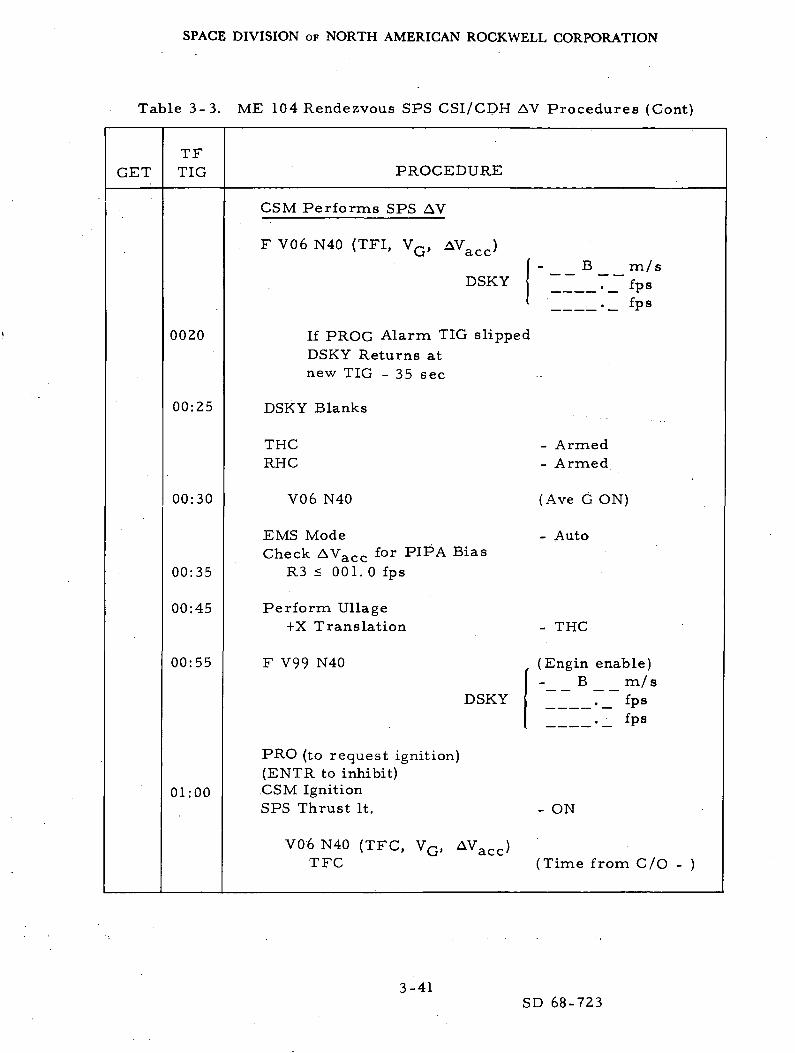
Table 3-3. ME 104 Rendezvous SPS CSI/CDH AV Procedures (Cont)
GETTFTIG
0020
00:25
00:30
00:35
00:45
00:55
01:00
PROCEDURE
GSM Performs SPS AV
F V06 N40 (TFI, VQ, AVacc)
B m/sDSKY ._ fps
. _ f p s
If PROG Alarm TIG slippedDSKY Returns atnew TIG - 35 sec
DSKY Blanks
THC - ArmedRHC - Armed
V06 N40 (Ave G ON)
EMS Mode - AutoCheck AVacc for PIPA Bias
R3 < 001. 0 fps
Perform Ullage+X Translation - THC
F V99 N40 (Engin enable)B m/s
DSKY ir__~_7 fPs
_._ fps
PRO (to request ignition)(ENTR to inhibit)GSM IgnitionSPS Thrust It. - ON
V06 N40 (TFC, VG, AVacc)TFC (Time from C/O - )
3-41SD 68-723

SPACE DIVISION OF NORTH AMERICAN ROCKWELL CORPORATION
Table 3-3. ME 104 Rendezvous SPS CSI/CDH AV Procedures (Cont)
GETTFTIG
01:01
C/0 +00:01
PROCEDURE
Discontinue Ullage
Monitor BurnEMS AV Ind. - decreaseN40: VG and TFCSPS PC Ind.
SPS Engine CutoffSPS Thrust It. - OFF
F V 1 6 N 4 0 (Eng C/O)TFC (time from C/O + )
AV Thrust A - OFF
Report: Engine Off
SPS ENG. INJ. VLV A IND (2) - CloseSPS He VLV tb (Both) - Bp
SPS GMBL MOTR P, Y-2 - OFFSPS GMBL MOTR P, Y-l - OFF
SCS TVC SERVO Pwr 2 - OFFSCS TVC SERVO Pwr 1 - OFF
EMS Mode - STBYRecord AV Ind.
PROF V16 N85 (VG Body)
Null VQ (x, y, z) if necessary
THC _ Locked
Key V82E (ORB Param. )F V16 N44 (HA, Hp, TFF)
3-42SD 68-723

SPACE DIVISION OF NORTH AMERICAN ROCKWELL CORPORATION
Table 3-3. ME 104 Rendezvous SPS CSI/CDH AV Procedures (Cont)
GETTFTIG PROCEDURE
PROF VI6 N85 (VG-Body)
PRO
F V37
MN Bus Tie (2)EMS Func.Trans Contr. PwrFCSM SPS A
Return to Step A
(exit P40)
- OFF- OFF- OFF- RESET/OVRD
3-43SD 68-723

SPACE DIVISION OF NORTH AMERICAN ROCKWELL CORPORATION;
in
"ctu£goO
V
_ g ~2 C 5° I! g.
w
„v-' a)
•§ §•«H C^ -^
ctn cu ' — 'W o.
2 ° c0 d 3
EH
CD(UU
5 ow «bo
W«
> m
< «
cc .2 -tj -w U3 £ a
Q
•do2oH
c .^ o3 •?-« ^
J
ZK-4
O
c c /a a. W K U}
0) - <U -"
rt 0) rt OJ""" M ^ M
g .2 g .SO M O MC O C On £ » £oj tn oj to^ ^ ' O K .
^ -^ ^ ^T7J * "o *t-H QJ (-( 0)
PO vD O >— ' < — ' •— < . ^t* OO--H ro --H f\]
ro ro VO^D r^ r^ ooc o c o mo") roco ^^
-N
co en tn en
o o o o ^ o o o
.-H +1 -H -H
O,
3 -0i C
in C .
C ^ £6 3 3
rO
. Ifl .H ^
^H C QJ
w i! a)0 00 nl C
•H - c -5^ " 'cy ^ c SS 'S m In
©
. "c"
Tj^ O
i on
S
}
00
° - ° - 0 - 0 -
i i i i
ro m ro on
-H -H -H' -H
xD LO ^OO ^^ O -^
<N] 0s CT^ rO
S S 2
OO rv] ro f-
CO O u"l Of\J OO
? ? ? 5% *x *x %<u QJ d) aj
W ' 02 U2 COu . u o u*£ ¥i 'Z, 'Z,o o , o o
»-« fSJ f! -^
*
•O
CO
<1J•d
0c
c3
o
tlo
^
-X-
OCO
CO
CO
rO
0)i—i
a)H
3-44
SD 68-723

SPACE DIVISION OF NORTH AMERICAN ROCKWELL CORPORATION
01
ID
OU
c;- e - 5 -0^1
w
0 s § _P^ ^ •
^ 'E.5 *~— i **-( _5 ° c0 . 3H O BH
Z
oi • •'
d h ""* 8.3O ""^
o So
1 £o:« J0 H
<g 0K U
0 "
W u,H
^^
> «<3 «l *
cc .2 -j;3 « S
CQ ^ — -Q
flj
C2U
H
C .^ o3 Z
w
Jb.Q
^
Kt)
m
O N ^
' > * - : - £ ^ • «
S " £ c ^ o ™ S e o . . .m D i< .2 ^H m "•£ h ^> ' ''U " ^ < T j t i i ' ' c r f ^ Q--0 ^
f"1 '> O r-i •*"* DC (U -5 - 4-* U "'"^
n x C L ) ^ H ' ^ O O ' ^ n J. r - I o U ^ • ' f H C -
S .2 £ 1 ^ S S' « • ^ ^ - 2° V, •" .2 — ^00 • K 2 — ' C J<! •
^ T J ^ , ^ ^ ^ 2 ^ ' " ^ ( H 3 " ^ n 3 ^ H ^
ijiij it i ij ijj if% "H"
C 7 ^ ^ H c n ( \ I r s l o o . C C(\j r*j ^~* ^o
d- ^
f\] sD O t*- Om ro m ro -^
m vo^ %o ' ' co ' co •
M - ^
ro ro ^ fO - ro
_(_)
U U 4-> W O U
^j j_i ^ (U oJ -AJco tn ^ C g to co i
0 0 2 '"> S 0 0
PH <U T3
xo in un TC00 r—. ^H O TjH
rg c> o^ c> m'vO cT- 0s CT^ O
2 ^ ^
co M PJ ro r^
oo o o ID o^fNJ fM OOINI r\j -H
O O U U U^ K> £> K>" K*
H' H H H H
S ^ ^ 2 2en in 03 to 10U U U O O2 Z Z Z ZO O O O O
^ <M <\] {^ Tt*
flo
JJ
Oco
w&to
ro
0)
3-45SD 68-723

SPACE DIVISION OF NORTH AMERICAN ROCKWELL CORPORATION
£0H
^ ID
• gL_(
_f_t
CO
w
rt
OH
COCDU
*-<
Oc/)
- o
w
J-l
(Q
en
C<1>
6goU
CD
t gto - — •-d
cj ' C
X .H
* e0) ^~'a
j-iO 01
g
z; a
jH
O^U
H**
> IIT
<! £•
co*-> tj2 °Q ~
<B•ao
0
F-i
C .rj O
a z
»
j
g
o .
a 'd T3i C
01 C '
6 *5in S h > > >— . C D . < O O
a & a £ in in in• § 0 - . S - . u .u ug S 6 g I f f
1-1 "^ o u u .
@ CQ CQ CQ •
O O (SJ ^ iTl O i — i fVl '— ' (Nl LH O f*0 rC C
00 2 5;
o o ( N j r v j m m ^ - i ^ H ^ - i ^ H i r i L n v
T ^ T ^ - ^ T f v D x D ^ ^ ^ T ^ - ^ ^
co cp en co en en
O o O o O o ° O ® O . O o
rJ rj CM rJ (M r\]-H -H -H -H -tt -H
- - * ~ - -
* ^ i u i 5i ^! m°^-< ° _ ( O _ , O _ H O , - - | , _ (
-H -H 4? --H •« -H
0^ 0^ 0^ 0^ 0^ 0^rO rO ro m m co
-H -H -H -H -H -H'
-*D — i r>") if) o^ 0s
ro rs] i— i [^ ^O — •
<N1 CO vD 00 00 O^rO G^ ~*O u~i co ro^H no
— < -H (N]
^D Tp no ro nj r\j^ 11 K M
> > > : > > >^J vj ^J %J vj vj
(U 1) (1J u CJ QJ
t/1 C/) C/3 C/3 I/) C/lU U O O O U2 Z Z Z Z Zo o o o o o
^H (M
ffi ^ K1/1 ° ^ Q K Q
u u u
'
i
•o0)01
s^ 'QJ
T3
o
0}c
^o
£0
'C;-
C!3
PJ
<*-!
O
inro
3-46
SD 68-723

SPACE DIVISION OF NORTH AMERICAN ROCKWELL CORPORATION
~a •"
H
(~*} ® '
0) C
U H
rt'oH
wC3
O2:
en0)u
• o
t-lQ
f-l
w
cM3w
en
C<u -ggoO
V
3
rth
<u 7?
H •=•
C3 'c'
s Ic.
° S
I5
t- oa7"3
fc
"3 4J
_0
2 £
JH
OO
w
J-1
^
<£;
c0rJ .— .
ti urt njh in3 -—Q
<DTJO
S0
H
c .h O
I Z
W
1 — )_I3hD
<;
ft•— )
1— '
O
CQ
_ (U QJ
- "c 'S - 5 § 2 >-,ri rt W T ' O 0 " ^ ' ~ ~ I i j" r ^ - " t o f r t ' ^ ^ r t " 1 C.5 c c > • - |
r 2 . t J o . ^ h § «• - • C X ^ '"'c o d < r t ^ c l ) ' ^ ' - H --i a; .5
m - ^ i H f l J " ^ a ; 2 o 1 S - ^ c g a ) G • •" o ^>j j f ^ r t C t i^ r t J - i ^ ' ' ^ " c ^ ^ " -i-« ^ ^
| a> c r .3 ^ s S « ^ 1 § 2 ° " • "^ s ^ S f ^ f u r t l e l l ^ s0 < S < H . 3 r t 2 £ f e © „
_^rt
co "3 tn w j_i1 U 0 ) Q J O O O O < 1 J O O
^ ? ~ * r * Z Z Z ^ ^ ^ t " *
o ^o trt iT) LT> in o LO in so— . ^ - . ^ H ,-H - fO <— < ~^ U~>
~^
O rg in m in m i n u i m^ T ^ O O v O O ^ s O ^ O
r o m m — « - ^ c o s O r o r n c orj
r ^ ^ ^ ^ H ^ H ^ _ M ^ ^
1
r n r o r o - H r H m r o r o o o
O
O O ° rS °
D flj QJ ^ (JJ
t n w w o o o ^ ^ ort rt rt * rtu o u ^ u
tn tn to o tnh h ^ 0 0 o ^ ^ Oo o o m o
^ ^ £ • * • * . . .v £ ) r j r n r o r o r o r o /r o n i — « ^ H - H ^ H ^ ^ < * -
PS] ro vO xD vO vO sDro 0s ^ v^ ^D v^ vO— fM (M (\J (NJ 1M
•— t .— i iM IN rvj <N) f\]
•*Q ^ f\J f\] M PO f^J1—1 i— i i — i i-* •— •
*TT >*""-- ^ r> fi M ^
C) C !) CD ~° ^ n ^
H H H £ S i" 1 £ ~ H > ' H > - H U 2 lS 5 ^ c S ^ S c o h o ^ o t / 1 ( i. > > ^ ^ o ^ 3 ; r ^ > 4 - > 4 ^ 4 - > ^ > — , v ^CL ' C^ S. °> — u — ^ _ < U 3 C 3 C 3 Q - - - ' r t
O O O O O O o ' H ' u v > i n i n i n ^ ^ ( - > a
2 2 2 2 2 Z 2 3 2 o u u u o S ^ ^O O G O O O U - n O c n ^ w u i w S O f a
. ^T" iv.
0U
T)
O
C
>
al<+H
*+*O
3-47
SD 68-723
SPACE DIVISION OF NORTH AMERICAN ROCKWELL CORPORATION
3. 3 RENDEZVOUS .
3.3.1 Study Objectives •
Although the SC 104 mission plan does not include an actual inflightconfirmation of CSM-active rendezvous capability by a single crew member,in the event LM-active rendezvous is not completed, the capability for aCSM rescue of the LM is mandatory. This capability, then, must be demon-strated through simulation. The objectives for this simulation study are:
1. Verify the software (COLOSSUS) rendezvous programs: POO,P17, P20, P34, P35, P40, P41, P47, and P76.
2. Verify the adequacy of G&C procedures for both passive andactive rendezvous.
3. Develop alternate procedures as required.
4. Evaluate the effects of trajectory deviations.
5. Evaluate the effect of navigation on MSFN errors.
6. Evaluate the effects of system error sources.
7. Determine the effect of a GNCS failure on the capability tocomplete a rendezvous.
8. Determine the effect of RCS jet or quad failure on the capabilityto complete a rendezvous. , :; '
9. Establish SM RCS propellant values for both active and passiverendezvous.
10. Provide a data base for postflight analysis.
3. 3. 2 Study Scope
The rendezvous study phase will be divided into three areas of investi-gation: CSM-passive rendezvous performance, CSM-active rendezvousperformance, and failure effects on rendezvous success and performance.
3-48
SD 68-723
SPACE DIVISION OF NORTH AMERICAN ROCKWELL CORPORATION
3.3.2.1 CSM-Passive Rendezvous
The CSM-passive rendezvous study will evaluate the nominal opera-tions and procedures onboard the CSM while the LM-active rendezvous, is inprogress. Nominal operation will include:
1. Acquiring the necessary observation data
2. Accepting and incorporating uplinked and voice-linked data
3. Monitoring LM actions and status both visually and in the CSMcomputer
4. Performing backup computations
5. Performing the required procedures for A V preparations andcount downs.
In addition, backup charts for L/M-active operations will be utilized, ifavailable, where CSM activities must respond to voice-link from the LM.
3.3.2.2 CSM-Active Rendezvous
The CSM-active rendezvous study will evaluate the rendezvous per-formance under both nominal and off-nominal conditions for each of the sevenevent times (except CSIi, which is nominally zero) at which CSM-activerendezvous may be initiated. This will include external AV activities andon-board computed A V operations, both with and without error sources.
3 .3 .2 .3 Failure Effects on Rendezvous Success and Performance
This portion of the study will evaluate both the dynamics and operationaleffects resulting from various failures during the CSM-active rendezvous.The ability of a single crew member to detect a failure and make a successfulrendezvous will be evaluated. Failure conditions may include CMC, IMU,or optics failure and RCS jet or quad failure. Suggestions for modificationsto the procedures will be made and/or evaluated.
3. 3. 3 Run Description
The majority of the runs will begin immediately following the scheduledLM burn. Normally the CMC will be initiated with a different state vectorthan is the RTSS in order to simulate MSFN errors. Each run requires theuse of the external visual displays, normally the SXT and always the dockingwindow. During prebraking, the docking window scene will just contain amoving, blinking light representative of the LM beacon. At braking distances,
3-49SD 68-723

SPACE DIVISION OF NORTH AMERICAN ROCKWELL CORPORATION
the scene will change to a view of an LM model using the GPVS. The testprocedures were derived from the Mission D Rendezvous proceduresDocument (Reference 5 ) and the CSM 103 AOH, but they include certainsimulation-determined and data requirement procedure's. The detailed testprocedures are listed in Table 3-6. i
3.3.4 Run Schedule Synopsis
The rendezvous study includes both LM-active and CSM-active rendez-vous. Run schedule synopses for both are presented in Tables 3-7 and 3-8.
3-50SD 68-723

SPACE DIVISION OF NORTH AMERICAN ROCKWELL CORPORATION
CU
1UO^
ex0)
CO
Pro
ce
du
re
a0)4J
CO
<UTJ0U
»—4o0oo
c0
• H
"exo
Xoooo
S
H
COhH5.UrOTl
nt0
W
0)
*
£^^ 3^ «° §• H TO-M kH•s 3«fH J^1
1 §< to
Q)
tt gtl «^ "oJ^ '-'
in o 4-1fM 0 C<Z 0 0
o^ U
m -j aj
O h . - §PH £OH <;
a5.5
i
4->
<
U
SC
Co
ntr
ol
r\j0)
"rt
3
i
ni
BM
AG
Mo
di
Man
eu
ver
o
Q
u0)U CO
< CO
1 1
Man A
ttS
C C
on
tro
l
CO
0Ua
nt
V
•FH
o*O
neu
ver
to A
n!
2
VT)OU
&0hn)H
0 |
S 's°p °^ i— i
O h PcJOn0,
HX
§ so r)
y V
21
Lo
ad:i
cs M
od
e -
P- •• •*-V (X
W O
• LO ^0 t**"
AS
C
ali
bra
tio
n
0U
Po
st C
DH
Op
era
tio
ns
!H
V*H
Ltc
h P
osi
tio
ns
>W
»— t
PO
§ u . *I OH
FD
AI/
GP
I P
wr
(bo
th)
SC
S E
lect
Pw
r - G
DC
,L
og
ic 2
/3 P
wr
- O
N
CM
C A
tt
- IM
UF
DA
I S
ele
ct -
1
/2B
MA
G
Mo
de
- A
TT
l/S
C
CO
NT
-
SC
S
roU*!<
hO
i— t
<1
SC
S S
ig C
on
d/D
R
Bia
g
U
£«U £< 2
1 '
o
liM CO£ U
DH OH
U °»r tlX 3DH ^1
cj0)enini-H
5 2^* OJ k2 N o
1 1 1^ CO CO
O -,-1 -H'rH 4-> 4->*=$ CX CL,co O O" 0 0
4-> M ha, a) <DO N N
>
OTJ
O• •Hcxco"CXo ^~.
CO
AS
-
ag
ain
st t
he
stc
srate
(st
art
tr
aje
cto
ry
CX0
<M
<D
Op
tics
in W
ind
ow
Mo
dD
ock
ing P
osi
tio
n
f V
37
E
52E
(U
*
CO
!"
o
o
c• I-laM0)
0
a.Q
0}o
O—IW
3-51SD 68-723

SPACE DIVISION OK NORTH AMERICAN ROCKWELL CORPORATION
CD
T)
UO
£
exCD-U
to
Pro
ce
du
re
aCD
</)
1 &— 4 ^ L _ lrO •" "
? s "0 1.2 3 n c» S 2' - > ; • < : §' 3 ^ ^ - S o " 1 ^ S H c ^J < 2 H a oay c o H ~ f _ , co c
s li H SB i"3 XX -| rt g -d.J «
: ^ *s s «£ *4J b^ * >-t U ^ - r - <(X ^ O s / "S)0^ l*H fl^O rig ggp Hw« ^ ^^ u
- 5 ^<S 9 i- "-w ^O i— ( CO 'Cpl j j Dj OJM rd
S. r « o! ..?g-« S S .» .go h K . S S t < ^ g05 o CD • CDPH CQ W H
. — .
o
O CDn fl0) — 'N w
r XCO XCJ
'IS Wcx, t-o ^>o ^^H >NCD CO
N ^
CO CT^ O
oU
o•H
•s
O
N
ffiQU4->CO
O
O-1
W
NO
IOO
•8
3-52SD 68-723

SPACE DIVISION OF NORTH AMERICAN ROCKWELL CORPORATION
Table 3-6. ME 104 Post CDH to Rendezvous Termination (Cont)
GETTFTPI Procedure
CDH Burn Completed
Switch Settings
FDAI/GPI Pwr . - BothSCS Elec Pwr . GDC/ECATrans Cont Pwr - ONRot Cont Pwr Direct (Both) - OFFAuto RCS Sel (B /D Roll-4) - OFF
FDAI ScaleRateAtt DB
- 5/1- Low- Max
FDAI SelectCMC AttEMS ModeEMS FuncBMAG Mode (3)Man Att (3)Optics ModeOptics ZeroOptics Drive
BothIMUSTBYOFFRate 2Rate CMDManZeroRSLV
Optics in Telescope Mode(Blinking Target)
*Zero in the SXT - adjustRemove Zero in SXTOptics Zero - OFF
SC Control - CMCCMC Mode - Free
Countdown to Operate
Operate (- ) ET
3-53SD 68-723
SPACE DIVISION OF NORTH AMERICAN ROCKWELL CORPORATION
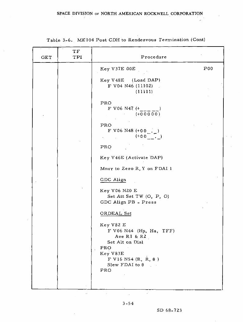
Table 3-6.. ME 104 Post CDH to Rendezvous Termination (Cont)
GETTFTPI Procedure
Key V37E OOE
Key V48E (Load DAP)F V04 N46 (11102) .
(11111)
PROF V06 N47 (+ )
( + 0 0 0 0 0 )
PROF.V06 N48 ( + 0 0 _ . _ )
( + 0 0 '._)
PRO
Key V46E (Activate DAP)
Mnvr to Zero R, Y on FDAI 1
GDC Align
Key V06 N20 ESet Att Set TW (O, P, O)
GDC Align PB - Press
ORDEAL Set
Key V82 EF V06 N44 (Hp, Ha, TFF)
Ave Rl & R2Set Alt on Dial
PROKey V83E
F V16 N54 (R, R, 6 )Slew FDAI to 9
PRO
POO
3-54
SD 68-723

SPACE DIVISION OF NORTH AMERICAN ROCKWELL CORPORATION
Table 3-6. ME104 Post CDH to Rendezvous Termination (Cont)
GETTFTPI Procedure
Call for Fuel Printout Q)
Key V37 E 20E
F V50 N18 (please mnvr)(R, P, Y)
a. Auto ManeuverSC Control - CMCCMC Mode - Auto
PROV06 N18 (R, P, Y)
Monitor on FDAIF V50 N18
b. Manual ManeuverSC Control - SCSCMC Mode - AutoMan Att - Accel CMD
PRORHC maneuver
F V50 N18Man Att - Rate CMD
c. Trim ManeuverF V50 N18
SC Control - CMCCMC Mode - Auto
PROV06N18
Monitor on FDAIFV50 N18
Key ENTR (when satisfied)RHC - LockedCall for Fuel Printout ©Enable Roll Jets B/DMove to LEB
Optics Zero - OFFOptics Zero - Zero (15 sec)
POO
P20
3-55SD 68-723
SPACE DIVISION OF NORTH AMERICAN ROCKWELL CORPORATION
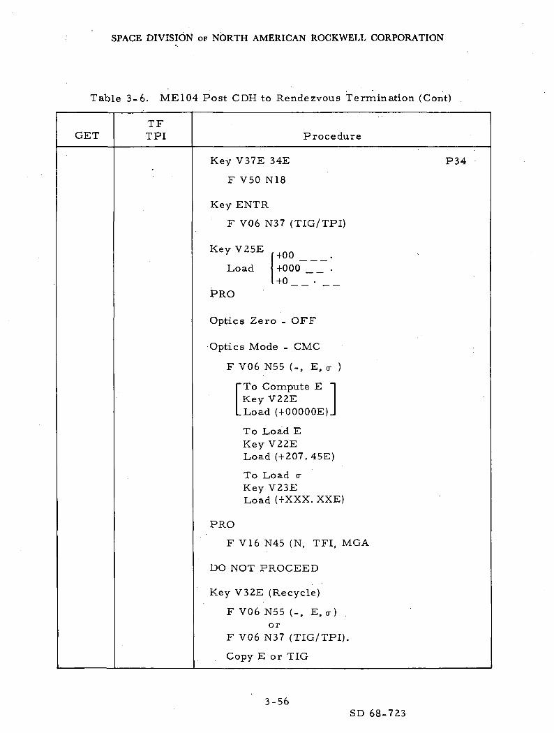
Table 3-6. ME 104 Post CDH to Rendezvous Termination (Cont)
GETTFTPI Procedure
Key V37E 34E
F V50 N18
Key ENTR
F V06 N37 (TIG/TPI)
Key V25E
Load
PRO
+00 _+000"+0
Optics Zero - OFF
Optics Mode - CMC
F V06 N55 (-, E, cr )
To Compute EKey V22E
LLoad (+OOOOOE)J
To Load EKeyV22ELoad (+207. 45E)
To Load <rKey V23ELoad (+XXX. XXE)
PRO
F V16 N45 (N, TFI, MGA
DO NOT PROCEED
Key V32E (Recycle)
F V06 N55 (-, E, <r )or
F V06 N37 (TIG/TPI).
Copy E or TIG
P34
3-56SD 68-723

SPACE DIVISION OF NORTH AMERICAN ROCKWELL CORPORATION
Table 3-6. ME 104 Post CDH to Rendezvous Termination (Cont)
GETTFTPI Procedure
PRO
F V06 N58 (H
Copy AV's
*EMS Func -AV SetSet AV Indicator to R2EMS Func -AV
PRO
F V06 N59 (AV
Copy Data
comp)
PRO
F V16 N45 (N, TFI, MGA)
Set ET - countdown
Compare Solutions
*Key V06 N52E
F V06 N52 ( tr CSM)
Key RLSE
F V16 N45 (N, TFI, MGA)
KeyV57E
F V51 (please mark)
Optics Mode - Man
Make Marks (one/min)
F V06 N49 (AR, AV, +1)
Accept : PROReject : Key V32E
P34
3-57
SD 68-723
SPACE DIVISION OF NORTH AMERICAN ROCKWELL CORPORATION
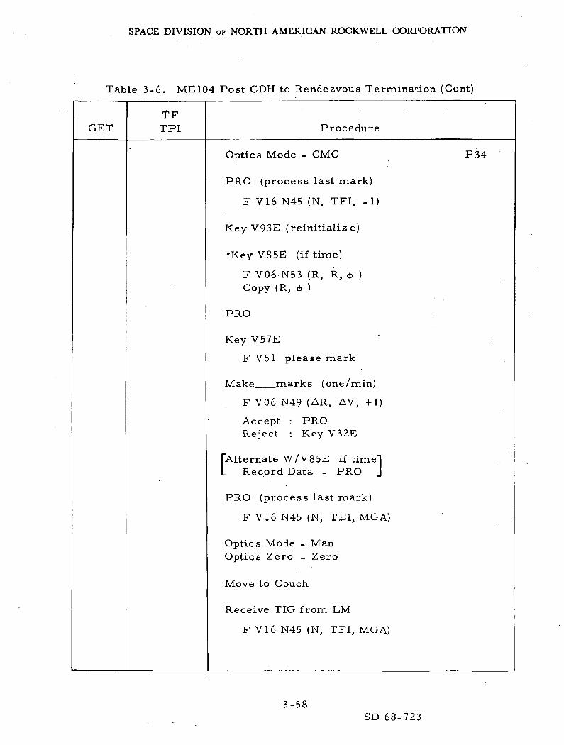
Table 3-6. ME 104 Post CDH to Rendezvous Termination (Cont)
GETTFTPI Procedure
Optics Mode - CMC
PRO (process last mark)
F V16 N45 (N, TFI, -1)
Key V93E (reinitialize)
*Key V85E (if time)
F V06 N53 (R, R, 4> )Copy (R, $ )
PRO
Key V57E
F V51 please mark
Make marks (one/min)
. F V06'N49 (AR, AV, +1)
Accept : PROReject : Key V32E
["Alternate W/V85E if time]L Record Data - PRO J
PRO (process last mark)
F V16 N45 (N, TEI, MGA)
Optics Mode - ManOptics Zero - Zero
Move to Couch
Receive TIG from LM
F V16 N45 (N, TFI, MGA)
P34
3-58SD 68-723

SPACE DIVISION OF NORTH AMERICAN ROCKWELL CORPORATION
Table 3-6. ME 104 Post CDH to Rendezvous Termination (Cont)
GET.TFTPI Procedure
PRO (final recycle)
F V06 N55 (-, E, <r )or
F V06 N37 (TIG/TPI)
Record E or TIG
PRO
F V06 N58 (Hp,
Record AV's
*EMS Func - AV SetSet AV Indicator to R2EMS Func - AV
PRO
F V06 N81 (V LV)CJT
Copy AV components
PRO
F V06 N59 (V LOS)
Copy VGLOS
PRO
F V16 N45 (N, TFI, MGA)
Reset ET
Call for Fuel Printout ®
Key V77E (+X axis track)
P34
3-59SD 68-723

SPACE DIVISION OF NORTH AMERICAN ROCKWELL CORPORATION
Table 3-6. ME 104 Post CDH to Rendezvous Termination (Cont)
GETTFTPI Procedure
09:00
08:30
Optics in Window Mode(blinking Tgt)Docking Position
F V50 N18 (please mnvr)
PRO (accept mnvr)
V06 N18
Monitor Mnvr. to COAS Track
F V50 N18 (please trim)
Key ENTR (accept trim)
F V16 N45 (N, TFI, MGA)
PRO (exit P34)
F V37
Key 41E
F V50 N18 (please mnvr)
Backup Data Procedure
Att DB - MinRate - LowSC Control - SCSBMAG Mode (3) - Att I/Rate 2Man Att (F, Y) - Min ImpRHC - ArmedDisable Roll Jets B/D
Bo re sight on LM (COAS)
Key V83E
F V06 N54 (R. R. 6 )
Maintain Boresight (COAS)
P34
P41
3-60SD 68-723
SPACE DIVISION OF NORTH AMERICAN ROCKWELL CORPORATION
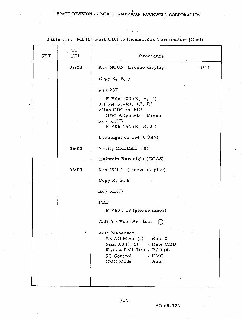
Table 3-6. ME104 Post CDH to Rendezvous Termination (Cont)
GETTFTPI Procedure
08:00
06:00
05:00
Key NOUN (freeze display)
Copy R, R, 6
Key 20E
F V06 N20 (R, P, Y)Att Set tw-Rl, R2, R3Align GDC to IMU
GDC Align PB - PressKey RLSE
F V06 N54 (R, R, 6 )
Boresight on LM (COAS)
Verify ORDEAL, (6)
Maintain Boresight (COAS)
Key NOUN (freeze display)
Copy R, R, 6
Key RLSE
PRO
F V50 N18 (please mnvr)
Call for Fuel Printout (3)
Auto ManeuverBMAG Mode (3) - Rate 2Man.Att(P.Y) - Rate CMDEnable Roll Jets - B/D (4)SC Control - CMCCMC Mode - Auto
P41
3-61SD 68-723
SPACE DIVISION OF NORTH AMERICAN ROCKWELL CORPORATION
Table 3-6. ME 104 Post CDH to Rendezvous Termination (Cont)
GETTFTPI Procedure
04:00
01:20
01:00
00:40
00:35
00:30
PRO
V06 N18
Monitor Mnvr to TPI Thrust Att
F V50 N18
PRO (last trim)
V06 N18F V50 N18
Key ENTR (accept trim)
F V06 N85 (V Body)Cj
Calculate BackupsCompare Solutions
EMS ModeEMS FuncLoad AV TPIEMS FuncEMS ModeLim Cycle
- STBY- AV Set
- AV- Auto.- OFF
BMAG Mode (3) - Att I/Rate 2
If PROG Alarm
TIG slippedDSKY clears atnew TIG - 35 secCOMP ACTY lightoff (exit R41)
DSKY Blanks
THC - ArmedRHC - Armed
V16 N85 (V_ Body)Lr
P41
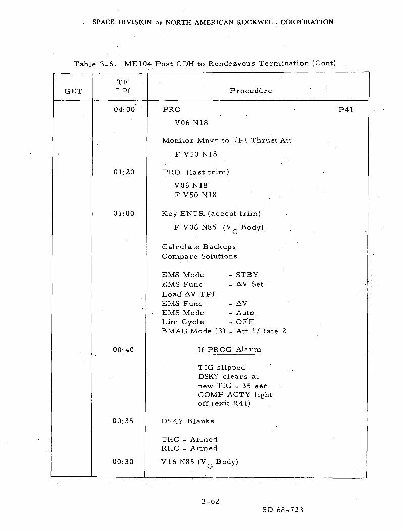
3-62SD 68-723

SPACE DIVISION OF NORTH AMERICAN ROCKWELL CORPORATION
Table 3-6. ME 104 Post CDH to Rendezvous Termination (Cont)
GETTFTPI Procedure
00:15
00:00
01:00
Call for Fuel Printout
F V16 N85 (VG Body)Null VQ'S w/THCStart ET countup
¥„ Zero
PRO (exit P41)
THGAtt DBEMS Mode,EMS Func
- Locked- Max- STBY- OFF
BMAG Mode (3) - Rate 2
Call for Fuel Printout ©
F V37
Key 35E
F V50 N18 (auto mnvr)
PRO
V06 N18 (mnvr)
Monitor mnvr to COAS
F V50 N18 (please trim)
PRO (for trim)
Key ENTR (to accept)
Call for Fuel-Printout @
F V16 N45 (N, TFI, MGA)
P41
P35
3-63
SD 68-723
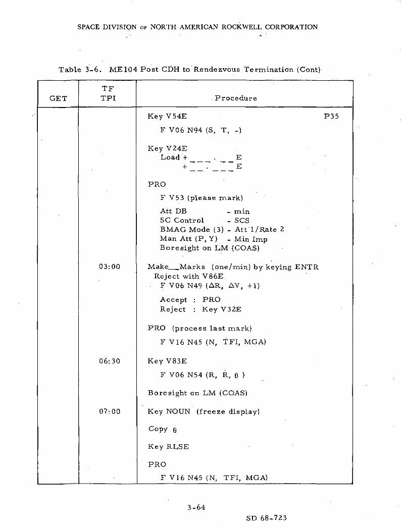
SPACE DIVISION OF NORTH AMERICAN ROCKWELL CORPORATION
Table 3-6. ME 104 Post CDH to Rendezvous Termination (Cont)
GETTFTPI Procedure
03:00
06:30
07:00
Key V54E
F V06 N94 (S, T, -)
P35
Key V24ELoad + E
E
PRO
F V53 (please mark)
Att DB - minSC Control - SCSBMAG Mode (3) - Att 1/Rate 2Man Att (P, Y) - Min ImpBoresight on LM (COAS)
Make Marks (one/min) by keying ENTRReject with V86E
F V06 N49 (AR, AV, +1)
Accept : PROReject : Key V32E
PRO (process last mark)
F V16 N45 (N, TFI, MGA)
Key V83E
F V06 N54 (R, R, 6 )
Boresight on LM (COAS)
Key NOUN (freeze display)
Copy e
Key RLSE
PRO
F V16 N45 (N, TFI, MGA)
3-64
SD 68-723

SPACE DIVISION.OF NORTH AMERICAN ROCKWELL CORPORATION
Table 3-6. ME 104 Post CDH to Rendezvous Termination (Cont)
GET
Exactly
TFTPI
08:00
09:30
10:00
Procedure
Key V54E P35
F V06 N94 (S, T, -)
PRO
F V53 (please mark)
Bore sight on LM (COAS)
Make marks (one/min) by keying ENTRReject with V86E
F V06 N49 (AR, AV, +1)
(Remove V50 N18 with ENTR)
Accept: PROReject: Key V32E
PRO (process last mark)
F V16 N45 (N, TFI, -1)
PRO (final Cycle)
F V06 N81 (V LV)
CopyVG ' s
Key V83E
F V06 N54 (R, R, 6 )
Boresight on LM (COAS)
Key NOUN (freeze display)
Copy R, R, 6
Key RLSE
PRO
3-65SD 68-723
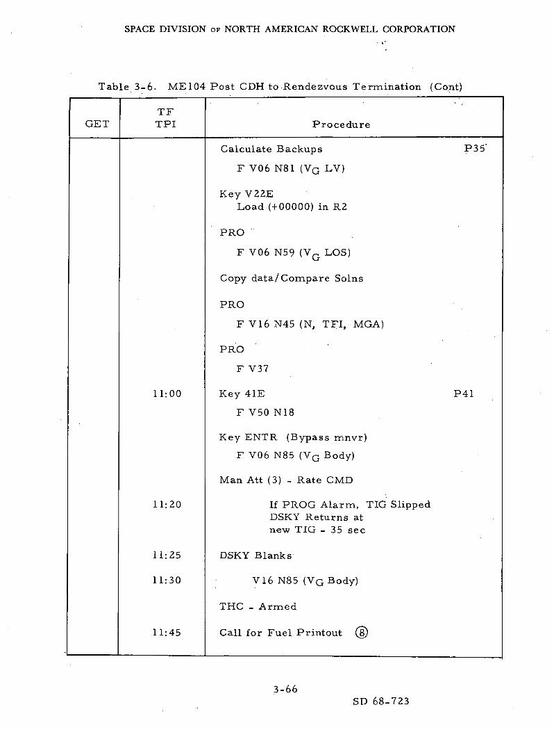
SPACE DIVISION OF NORTH AMERICAN ROCKWELL CORPORATION
Table 3-6. ME104 Post CDH to Rendezvous Termination (Cont)
GETTFTPI Procedure
11:00
11:20
11:25
11:30
11:45
Calculate Backups P35'
F V06 N81 (Vq LV)
Key V22ELoad (+00000) in R2
PRO
F V06 N59 (VG LOS)
Copy data/Compare Solns
PRO
F VI6 N45 (N, TFI, MGA)
PRO
F V37
Key 41E P41
F V50 N18
Key ENTR (Bypass mnvr)
F V06 N85 (Vq Body)
Man Att (3) - Rate CMD
If PROG Alarm, TIG SlippedDSKY Returns atnew TIG - 35 sec
DSKY Blanks
V16 N85 (VG Body)
THC - Armed
Call for Fuel Printout (§)
3-66SD 68-723

SPACE DIVISION OF NORTH AMERICAN ROCKWELL CORPORATION
Table 3-6. ME104 Post CDH to Rendezvous Termination (Cont)
GETTFTPI Procedure
12:00
14:00
F V16 N85 (VG Body)
Null VQ'S with THC
PRO (exit P41)
Call for Fuel Printout (9)
THC - Locked
F V37
Key 35E
F V50 N18 (auto mnvr)
Key ENTR (bypass mnvr)
F V16 N45 (N, TFI, -1)
Key V54E
F V06 N94 (S, T, -1)
Key V24ELoad + E
E
P41
P35
PRO
F V53 please mark
Man Att (P, Y) - Min Imp
Boresight on LM (COAS)
Make LM Marks (one/min) by keying ENTRReject with V86E
F V06 N49 (AR, AV, +1)
Accept : PROReject : Key V32E
3-67
SD 68-723
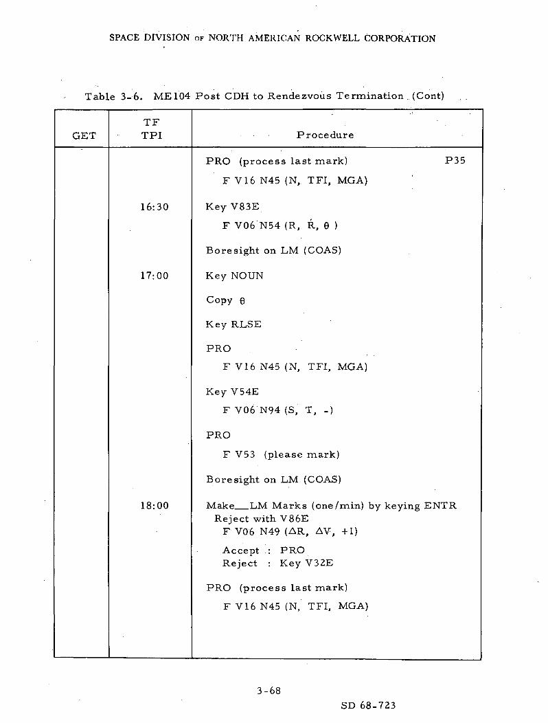
SPACE DIVISION OF NORTH AMERICAN ROCKWELL CORPORATION
Table 3-6. ME 104 Post CDH to Rendezvous Termination .. (Cont)
GETTFTPI Procedure
16:30
17:00
18:00
PRO (process last mark) P35
F V16 N45 (N, TFI, MGA)
Key V83E
F V06 N54 (R, R, 6 )
Bore sight on LM (COAS)
Key NOUN
Copy 6
Key RLSE
PRO
F V16 N45 (N, TFI, MGA)
Key V54E
F V06 N94 (S, T, -)
PRO
F V53 (please mark)
Bore sight on LM (COAS)
Make LM Marks (one/min) by keying ENTRReject with V86E
F V06 N49 (AR, AV, +1)
Accept : PROReject : Key V32E
PRO (process last mark)
F V16 N45 (N, TFI, MGA)
3-68
SD 68-723

SPACE DIVISION OF NORTH AMERICAN ROCKWELL CORPORATION
Table 3-6. ME104 Post CDH to Rendezvous Termination (Cont)
GETTFTPI Procedure
Exactly 19:30
20:00
21:00
PRO (final cycle)
F V06 N81 (VG LV)
Copy VQ
Key V83E
F V06 N54 (R, R, 6 )
Boresight on LM (COAS)
Key NOUN (freeze display)
Copy R, R,6
Key RLSE
F V06 N54 (R, R, 6 )
PRO
Calculate Backups
F V06 N81 (VG LV)
PRO
F V06 N59 (VG LOS)
Copy/Compare Solns
PRO
F VI6 N45 (N, TFI, MGA)
PRO (Exit P35)
F V37
Key 41E
F V50 N18 (R, P, Y)
P35
P41
3-69
SD 68-723

SPACE DIVISION OF NORTH AMERICAN ROCKWELL CORPORATION
Table 3-6. ME 104 Post CDH to Rendezvous Termination (Cont)
GETTFTPI Procedure
21:20
21:25
21:30
21:45
22:00
Key ENTR (bypass mnvr)
V06 N85 (VG Body)
Man Att (3) - Rate CMD
P41
If PROG Alarm, TIG slippedDSKY Returns atnew TIG - 35 sec
DSKY Blanks
V06 N85 (VQ Body)
THC -. Armed
Call for Fuel Printout (To)
F V 1 6 N 8 5 (VG Body)Null VG' s with THC
PRO (Exit P41) .
Call for Fuel Printout
THC - Locked
*Call for R, R data (RTSS)
F V37
Key OOE
SC Control - SCS
Key V83E
F V06 N54 (R, R, 6 )
POO
3-70SD 68-723

SPACE DIVISION OF NORTH AMERICAN ROCKWELL CORPORATION
Table 3-6. ME 104 Post CDH to Rendezvous Termination (Cont)
GETTFTPI Procedure
SC Control - SCS POOAtt DB - MinBMAG Mode (3) - Att I/Rate 2Check LOS Rates
*Call for R R dataCompare R, R, LOS Rate
with LM Radar Data
Man Att (P, Y) - Min ImpBo re sight on LM - COAS
Man Att (3) - Rate CMD
Key V83 if LM not burned
F V16 N54 (R, R, 6 )*Call for R, R data
F V16 N54 (R, R, 6 )
Compare R & R w/RRdata
PRO
Check LOS Rate/Compare w/RR data*Call for R, R data
LOS Control & Braking
Auto RCS Sel B/D Roll - MNAEMS Func - AVEMS Mode - Auto
Key V37E 47E P47
F V16 N83 (AV Body)
THC - Armed
Key V83E if LM not burned
F V16 N54 (R, R, 6 )
3-71SD 68-723

SPACE DIVISION OF NORTH AMERICAN ROCKWELL CORPORATION
Table 3-6. ME104 Post CDH to Rendezvous Termination (Cont)
GETTFTPI Procedure
Perform Braking
Perform LOS Control(Key V60 as Required)
Call for Fuel Printout for BrakingBefore and After
Call for frequent R, R data
Braking Gates
P47
R
1. 0 nmi
0. 5
0. 25
1000 ft
R
25 fps
15
10
5 fps
3-72
SD 68-723
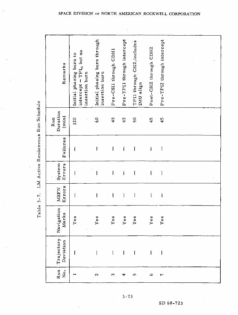
SPACE DIVISION OF NORTH AMERICAN ROCKWELL CORPORATION
CO
hrt
.Scu
rto
rt H->3 rt
Q
6cuCO
CO
faCO
5rto
•1-4
rtCuO•i-i
jecto
ry
rtfH
H
c;3rt
ji-_iifc
rt• t-4
S
COcut-l
•I-l
CO
0
wCO
0
w
CO
h
riation
cup
.o
XIbO3O
O )4o rt xl
-!-> H->
rt 3 c
bD PH fl bOfl H m C'to | J3 'io
i— i o +•> i— irt LJ M rt£ CU « 3.TH +J CO .Tnf-< H (H fHC R H R
O OCM vOi— I
1 1
1 1
1 1
CO COcu cu
1 1
•-I CM
rt3XI
rtio
nin
se
ffiP .U
thro
ugh
i— ii-icoUi
cu
m•*
1
1
1
COcu
1
rn
inte
rce
pt
thro
ugh
i— it-H
PHHl
CU
PH
m
^
1
1
1
COcu
1
«•
.inclu
des
CMi— icoUXIbO3o rt
• — i
H *4
o0
1
1
1
COcu
1
m
CM
ffiP0
thro
ugh
CMi— icoUi
CO0
PH
m<*
1
1
1
COcu
1
"°
a<uCJ
(U
"rt• 1-4
XIbO
0
xj
CM>—l
PHH
cu
PH
in
-*
1
1
1
COcu
1
r-
0)i— H
3TJ
CUXO
coti
rt
isltu
T3flcu
Ioo
XIrt
3-73
SD 68-723
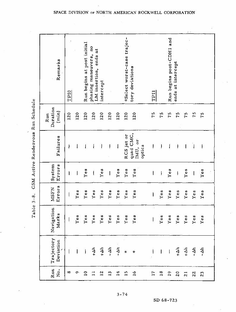
SPACE DIVISION OF NORTH AMERICAN ROCKWELL CORPORATION
COAth
£CO
ej
fl0 -^
a £ cp 'SQ ~
COtoM
t— i• !-l
r
g »<u o1o fc
cfr W
2 S« h
S w
ao
•g co
CO *«.r-i rd> 5!rd ^
o oti ^CO .S''
°"~~i ^fd cy
§ ort
,u
«J -^s § *• ^rt ^ +j' co" * <uS Sg Scu ^ " V »
4-> fl) -T 4-> fl
"* a S m °2 O LJ •!-"
S g '^ 9 *« C JH 40 fe .H
So hn <" ^ >Jj gO CO CO •*-" CO
o 'to "* >H • ^J «>v ""*
S § JgS | ^^ cuH Oj U J .5 * ° H
o o o o o o o o o mP O t M c M ( M N c \ J ( M r J < M f -
>-i r ^
° "S ^ o1 1 1 1 1 1 1 -u . » 1
C/5 ^ t) ."(j td s +->
OC| cr1 M O
CO CO CO CO CO| | co | co | co co co |
c o c o c a c o c o c o c o c oj c o c o c u c o c o c o c o c o |X : * > H > < ! * > < > H X
c o c o c a c o c o c o c o c oj c o c o c o c o c o c o c o c o |
v
J* jH j-, j-j
| | | >J ^1 ^4 ^J "TV If \+ + 1 1
OO CT^ CO ""H (\J CO ^^ ID vO f1 — 4 i — I F — I r M i — l i — I r — 1 I — *
T)ard
^E
QU
CO COO 0CX MCO ®
C fl
'S'-s43 *. CO
§ T3
P* CO
m m m m 'n IDr^ r^ r~ t«- f~ t*-
1 1 1 1 1 1
CO CO CO| CO | CO | CO
CO CO CO CO CO COCO CO CO CO CO CO
^ >H X ^ >H >,
CO CO CO CO CO COCO CO CO CO CO CO
43 43 43 431 1 <1 < <1 <1
+ + 1 1
CO O O i— i (vj CO-H 'H (NJ N 00 (N]
COI—IsCO
o
rt
c2CO
oNCO
cco
o
ooro
CDi—i43
3-74
SD 68-723

SPACE DIVISION OF NORTH AMERICAN ROCKWELL CORPORATION
Rem
ark
s
Ru
nD
ura
tio
n(m
in)
Fail
ure
s
6 2« oto *•"rJTw
to
CO £S w
Nav
igati
on
Mark
sT
raje
cto
ryD
ev
iati
on
ri *
Ej • w ti
«• tM «J !L M ? oi j r ! i < ^ v 2 M
w g O w C " r t - S ^ Q S«» .2 J, ^ «J .2 ti co qj U '
£3 Is " S S 3 s g 52 « ^s 2 S Si1"! 1o ^ c o ^ g ^ W r t ^ ^ o ,' >s -H -H ' >,
1 2 « 15 o S•~~* U C^J -j W i— i y *y* h^
W -^ OH d ^ CO .S, Q Q--- H oJ CD -::- O O
i n i r i o o o o o o o o o o o
JH U JH OS S
41—1 * 1 1 1 1 1 1 1 """> w 1 1w 'rt & -H w ^ t3 -^
to to co to co co to
t o t o c o t o t o c o t o t o c o c o
c o c o c o t o c o c o c o c o c o t oo ) 0 ) | a > c u ( u c u ( U ( u a ) < u | |
* * 1 1 1 < < < ] . < * * I I+ + 1 "
s s ^ ^ s ^ s ^ ^ s ? ; ^ ^
CO
osi
CM
PO
Ho•H
Vi
•MO
EH
0)
D
O
CO3O
Isl
C<urt
<u
C/J
U
ooiro
cdH
3-75SD 68-723
SPACE DIVISION OF NORTH AMERICAN ROCKWELL CORPORATION
3.4 ENTRY
3.4.1 Study Objectives
Study objectives are as follows:
1. Substantiate the capability of the integrated subsystem to performan automatically steered trajectory under nominal and off-nominalentry state vector, spacecraft, and landing site conditions.
2. Substantiate the capability to perform a manually steered GNCSentry for nominal and off-nominal landing site conditions.
3. Demonstrate capability to perform an entry with the GNCSinoperative.
4. Substantiate EMS as a backup display and verify adequacy of thescroll pattern.
5. Establish propellant budgets for entry.
6. Establish contingency procedures dictated by new panelconfiguration*
7. Verify nominal and backup G&C procedures.
8. Substantiate EMS, constant bank, and rolling entries.
9. Provide a data base for postflight analysis.
10. Verify the related COLOSSUS programs. (P61, P62, P63,P64, P67)
3. 4. 2 Study Scope
During the entry study phase, the G&C events that occur between theend of the deorbit burn and jettison of the apex cover prior to drogue chutedeployment will be evaluated. For particular cases, SPS deorbit and RCSdeorbit phases will be included to provide continuity. The three basic entrymodes will be substantiated for ME .104, the major portion of the evaluationhaving been accomplished during ME 101. Particular emphasis will be givento the verification of the COLOSSUS entry programs. The three entry modes
3-76
SD 68-723

SPACE DIVISION OF NORTH AMERICAN ROCKWELL CORPORATION
are the automatic GNCS, the manual GNCS, and the .SCS. The modes aredescribed below, and a simplified block diagram of each is shown inFigure 3-1.
1. Automatic GNCS Entry. In this entry mode, the crew primarilymonitors trajectory parameters and vehicular dynamics,
2. Manual GNCS Entry. In this entry mode, the crewman willsatisfy CMC steering commands displayed on the FDAI withrotation control inputs into the SCS for roll attitude control.
3. SCS Entry. In this entry mode, the crewman manually controlsthe CM attitude by monitoring the FDAI and utilizing the rotationcontrol. The crewmen must control the lift vector such that noviolations of tangency rays on the EMS scroll occur. For somecases, transition to an SCS entry from a GNCS entry, simulatinga CMC malfunction, will be accomplished.
3.4.3 Run Description
The entry study phase will cover the G&C events from CM/SM separa-tion to drogue chute deployment. This includes the preentry phase prior to0. 05 g and the atmospheric entry phase after 0. 05 g. During the preentryphase, the CM is oriented to the inertial attitude required for a heat shield-forward aerodynamic trim condition at 0. 05 g and maintains this inertialattitude until 0. 05 g. During the atmospheric entry phase, the CM is"steered" to a preselected target by rotating the CM about the wind axis(roll) with rate damping in the pitch and yaw axes. The CMC and crewfunctions after CM/SM separation are described below for each of the threebasic entry modes.
1. Automatic GNCS Entry. The detailed test procedures and theinitial switch positions for the display panels are presented inTable 3-9.
2. Manual GNCS Entry. The only difference between a. manual GNCSentry and an automatic GNCS entry is that the CM attitude iscontrolled by the astronaut using the rotation control rather thanthe entry DAP. The astronaut uses the CMC steering commandsthat appear on the FDAI attitude error needles for attitude con-trol information. Manual maneuver control is selected by aclockwise rotation of the translation control.
3. SCS Entry. When in the SCS entry mode, the astronaut manuallycontrols the vehicle attitude using the rotation control and
3-77SD 68-723
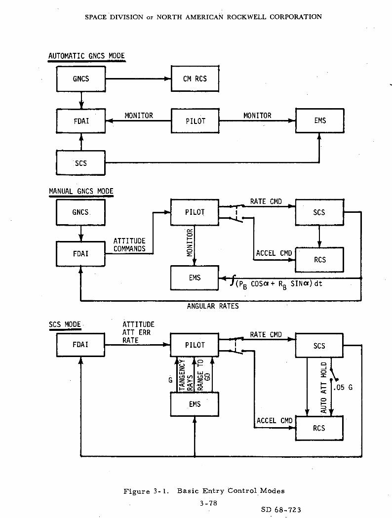
SPACE DIVISION OF NORTH AMERICAN ROCKWELL CORPORATION
AUTOMATIC GNCS MODE
GNCS CM RCS
FDA IMONITOR
PILOTMONITOR
EMS
SCS
MANUAL GNCS MODE
GNCS
FDA I
SCS MODE
FDA I
ATTITUDECOMMANDS
PILOT
oc.o
RATE CMD
SCS
ACCEL CMD
EMS
RCS
* /(P COS«+ R SIN«)dt
ANGULAR RATES
ATTITUDEATT ERRRATE PILOT
CD CO
_ RATE CMD1
EMS
SCS
ACCEL CMD
I.05 G
RCS
Figure 3-1. Basic Entry Control Modes
3-78SD 68-723

SPACE DIVISION OF NORTH AMERICAN ROCKWELL CORPORATION
monitoring the FDAI ball and EMS displays. Several controltechniques can be used, including a rolling entry and constant-bank profiles.
3.4.4 Run Schedule Synopsis
The run schedule synopsis is presented in Table 3-10. Included inthe schedule is the flight mode utilized, the type of initial condition statevector, the target, CM L/D, control mode, estimated time per run, and acomment as to objective.
3-79SD 68-723

SPACE DIVISION OF NORTH AMERICAN ROCKWELL CORPORATION
•G 0U .rt
."rt ."t J
^ oft
QJ
Sw
itch
Nam
0) .c o
•S .24-> -U. r_| .,_)
> M .
» f i
SojzA-l->
1 — 1GJ .c o
r? £••
M *S [i| 2 tq rt hu f J u r n f a ^ t h t n hftoooSooo
e|• J &.
a « c-o-o '«> 5 5C C O ,-H ^H—' .rt O O "-1 IP 0)
• ~*4 _ o, rvW CO M M W 0 0O i f t Q O o O n t ,t o c O ( j r t a a> > > 2 2 s s s« < w w u u o_
o
oinir> V
§ S r o o ' o i
•acni
hih fl•S 2 S S^ »«
._, M M E) -"3^ < < < .ti fi .tJS P P P u .5 sU rt rt rt < .-I <
<JZ
^
. — .
d.o(U
1 — I0)M
Orto3
ffio z)-H ^H
ffi O
a>
a
Rat
eT
ran
s co
ntr
ol
AC
/DC
CVJ
rmal
oc
S0
^H
Ro
tary
co
ntr
o
rtS f3-!
O O
S"
CL)
>H O
O u
a m
w UP >W H
rx_
PQ
I"is*— ,CM
OO
.,_,t)
(1)o&
Ro
tary
co
ntr
oS
C c
on
tro
l
ZO
CO
M
Oa
0
^_^
AU
TO
<uT30
SUSo
ffiHOPQ
DA
I/G
PI
rt
. ^^
RA
TE
2
m
BM
AG
mo
de
(
UWUP 20 0
V
o
CS
ele
ctr
on
ic i
MA
G p
ow
er
(2
en PQ
is— r*—
j
NO
RM
A1
OF
F
01 j_>
ft >Vi ^
PSUwH<!rt
O
HenU
H
ftWO(J<
H5
O
5o"o
SP
S g
imb
al
m
't*1
<
O i O
S
M R
CS
pro
pel:
CS
trn
fr*
CS
co
mm
and
o rt rt
pwprt
O
o o o
0) ^tiO '~H
rt ? no ^ ut— , c/!3 m"3 S °M W o
ao
(0oa
SUo
o•|en
•4-*
Urt(U<ai
"H0)
r/\
U•ii-
O4->
O
CO
(0o
U
I1— I0)C
Rt
li0)
a
rtH
3-80
SD 68-723

SPACE DIVISION OF NORTH AMERICAN ROCKWELL CORPORATION
Table 3-9A. ME 104 Automatic GNCS Entry
Step Procedure Expected
REQUIRED
CMC - ONISS - ON . • •SCS - ON
Set display panel switcherSet event timer
Count up event timer at start of program
K e y V S Y E O O EAlign FDAI 2ManAtt — Accel CMDManeuver to separation attitude
Roll = 1 8 0 . 0 DECPitch = 1 8 0 . 0 DECY a w = 4 5 . 0 D E C
CM/SM sep (both) —on (up)RCS TRNFR —CMRCS CMD — ON
Maneuver to entry attitude
RollPitchYaw
0.0 DEC55.0 DEC
0. 0 DEC
Auto RCS SEL A/C ROLL(4) —OFFAuto RCS SEL CM2(6) — OFF
(Dl, D2, A3, C4, D3, B4)
K e y V 3 7 E 6 l EFL V06 N61
Impact lat . ; DEG•Impact long . DEGHds up/dn
IF reject V25E load dataAccept PRO
FL V06 N60 (Entry Data)G max . GV pred . FPSGamma El . DEG
RecordPRO
3-81SD 68-723

SPACE DIVISION OF NORTH AMERICAN ROCKWELL CORPORATION
Table 3-9A. ME 104 Automatic GNCS Entry (Cont)
Step Procedure Expected
10
11
12
FL V06 N63RTOGO (0. 05g to spl) ____ .VIO (at 0. 05g) _____ .TFE __ B __
EMS mode — STBYEMS func —Test 5
Set scroll patt. to 37KEMS func — RNG set
Set RNG ind for RTOGOEMS func — Vo set
Align scroll to display indEMS func — EntryPRO
P62 (auto select by P6l)IF FL V37
Key 62E
FL V51 N2522211 (Request CM/SM sep)
PRO
FL V06 N61Impact lat ___ . __
NMFPSMINSEC
DECDECImpact long ___ . __
Hds up/dn ___ . __PRO (If rej V25E load new data)
DSKY P63EMS mode Auto
Align FDAI 2BMAG MODE (3) — rate 2
V06 N64 (monitor)G . __ _ GVI . FPSRTOGO ,~_ NM
Check RTOGO agrees with EMSMAN ATT(3) — Rate CMDSC CONT — CMC
3-82
SD 68-723

SPACE DIVISION OF NORTH AMERICAN ROCKWELL CORPORATION
Table 3-9A. ME 104 Automatic GNCS Entry (Cont)
Step Procedure Expected
13
14
15
16
DSKY — P64 (0. 5g)
0. 05g sw —On (up)EMS roll —On (up)
V06 N68 (MONITOR)BETAVIH DOT
DSKY — P67 (0. 2g)
V06 N66 (MONITOR)BETACRSRNG ERRDWNRNG ERR
VI 6 N67 (MONITOR)RTOGOLATLONG
MONITOR ALTIMETER
DEGFPSFPS
DEGNMNM
NMDEGDEG
3-83
SD 68-723
SPACE DIVISION OF NORTH AMERICAN ROCKWELL CORPORATION
3.5 IMU ALIGNMENT
3.5.1 Study Objectives
Study objectives are as follows:
1. Determine the accuracy of the IMU orientation as performed by thecrew using the sextant (SXT) for both the CSM and LM/CSMconfigurations.
2. Determine the accuracy of the IMU orientation as performed by thecrew using the crewman's optical alignment sight (COAS) for theLM-off configuration.
3. Determine the accuracy of alignment of the IMU using the SXTfor both LM-on and LM-off configurations.
4. Determine the accuracy of alignment.of the IMU using the COASfor the LM-off configuration.
5. Verify the operational integrity of the IMU orientation program(P51) and IMU realignment program (P52).
6. Verify the operational integrity of the backup IMU orientationprogram (P53) and backup IMU realignment program (P54).
7. Determine the time and RCS propellant required to perform eachIMU alignment and realignment.
8. Evaluate the related GfcC procedures.
9. Provide a data base for postflight analysis. .
3. 5. 2 Study Scope
This portion of the study will evaluate the capability to perform the IMUorientation, the accuracy of the determination, and the RCS propellant requiredfor the alignment tasks. The IMU alignment that occurs before each of theseven SPS burns, except Burn 6, will be simulated. IMU orientation deter-mination will be simulated, in addition to alignment, for SPS Burns 1, 2,and 5. IMU alignment prior to the rendezvous operations, prephasing and
3-84SD 68-723

SPACE DIVISION OF NORTH AMERICAN ROCKWELL CORPORATION
Table 3-10. Entry Run Schedule
DeorbitFlight •Mod,-
GS,N/extiV
G«.N/3»extiV
GS.N/MTVC
GfcN (over burn)
GJ.N (under burn)
SCS auto TVC
3 a SCS autoTVC
SCS auto TVC/MTVC
GfcN/ext iV
Reent r ies only
NA
Ent ryrlichtMode
GC.N auto
\rSCS-EMS
\ iGS.-N manual
G&N auto
1 rGfcrN manual
1fSCS-EMS
1tConstant bank
CNCS man/SCS
1Rolling
Hun
Prior todt-nr
1
>U bu rn
f
End ofdeorbi t burn
1 t
400 k
^End ofdeorbit burn
1400 k
E n t r yState
Vector
Nominal
1Over burn
Under burn
Nominal
1 t
Nominal
1 >
TaI. at
rent/Long
Nominal
J[80 center
30 center
Nominal
1 p
Nom nalJV
Nominal
30 off center
60 off center
80 center
80 center
30 off center
60 off center
60 off center
Non-
30 0
nal
ff center
60 off center
Nom nal
Nom inal
30 off center
60 off center
Nominal1
1y
30 off center
60 off center
TBD fromrun
L/D
Nominal
i p
High
Low
Nominal
^i
Low
Nominal
j
Nominal
1 t
AllControl
DAP
,,
Rate orACCEL CMD
\ t
DAP
,,
Rate CMD
ACCEL CMD
ACCEL CMD
Rate CMD
ACCEL CMD
Rate CMD
^ACCEL CMD
iRate CMD
{
ACCEL CMD
R.INo. of
R u n g
1
2
1
1
,
6
,
3
EstTimeperRun
...
"*
<•
*
s
*
r
1 i 35
i1 ; 35
1 35
1 35
1
I
1
1
1
1
1
1
1
1
1
1
1
1
2
2
2
1
35
35
35
35
35
25
25
25
25
25
25
25
25
25
35
35
35
25
TotalKN!
Tim<!
f
'
'
<•
:-
35
35
35
35
35
35
35
35
35
25
25
25
25
25
25
25
25
25
70
70
70
25
f loninteni *
Monitor CMC, and(CMS. V e r i f y DAP
V e r i f y backup
Pilot flies CMCatt i tude e r ror nee'lles;~Time for above
23 schedule r u n s arelisted in SP.S AV
Moni to r CMC andobserve CMC t rendsfor d i f f e r e n t tareet ,locations
Evaluate crew
CMC commands for
locations
Evaluate the backupent rv technioue
: C M C fa i l s d u r i n creen t ry and EMS
3-85
SD 68-723

SPACE DIVISION OF NORTH AMERICAN ROCKWELL CORPORATION
Table 3-10. Entry Run Schedule (Cont)
FailureMode
Roll jet drvrhrd over
Pitch jpt drvrhrd over
Yaw jet drvrhrd over
Roll direct collhot short
Pitch direct coilhot short
Yaw direct coilhot short
Yaw BMAG Zop^n
Roll a\v amphrd over withno opp jet
EntryFlightMode
O&N auto/man
1
G&N
i
GfcN man
RunInitiation
End ofdeor
1
l)it burn
r
EntryState
Vector
Nominal
4
TargetLat/Long
Nominal
if
L/D
Nominal
<J
AltControl
Rate CMD
1r
Total estimated time includea only run time anduplinking time
EatNo. of
Runa
1
1
1
1
1
1
1
1
CatTimeperR u n
(min)
15
35
35
'35
35
35
35
35
'
TotalEat
Time(min)
35
35
35
35
35
35
35
35
1065
Comrrmnt H
Failure at « < 0. 05
Failure at g ^ 0. 05
Failure at g «• 0. 05
Failure at « > 0. 05
Failure at q ^0. 05
Failure at 2 < 0. 0!
Failure at 2 ' 0. Or
Failure at s > 0. Or
3-86
SD 68-723

SPACE DIVISION OF NORTH AMERICAN ROCKWELL CORPORATION
post-TPIj, will be simulated. The alignment of the IMU to one of threeorientations will be investigated: the "preferred" orientation, which is theoptimum platform alignment for a specific burn; the "nominal" orientation,which is the local geocentric orientation; and the "REFSMMAT" orientation.The "landing site" orientation will not be investigated. For those SPS burnsor rendezvous operations performed in the LM-off configuration, the IMUorientation and alignment using the crewman's optical alignment sight (COAS)will be simulated.
3. 5. 3 Run Description
Prior to each of the seven SPS burns (except Burn 6) and the rendez-vous operations, post-TPIj, and prephasing, the IMU is fine-aligned to oneof the three orientations. If the IMU has been turned off or has been allowedto drift for. an extended period of time, the existing alignment must first bedetermined. The IMU orientation determination is accomplished using pro-gram P51. The IMU alignment is then performed using program P52 and,time permitting, occurs on the succeeding nightside portion of the orbit. Inthe contingency of an optics failure, the IMU orientation determination andalignment may be performed using the COAS. COAS utilization requires amodified program procedure; the IMU orientation is accomplished using thebackup IMU orientation program (P53), and the alignment is performed usingthe backup IMU realignment program (P54). The detailed procedures foreach of these programs are presented in Tables 3-11, 3-12, 3-13, and 3-14,respectively.
3. 5.4 Run Schedule Synopsis
Table 3-15 presents the schedule of runs that will be used to verify theIMU and backup IMU orientation determination and alignment programs.The runs are categorized as to SPS or rendezvous burn, number and type ofrun, IMU orientation utilized, vehicle configuration, programs verified,error sources, control modes, and simulator run times. The total numberof runs scheduled is 31, of which 17 use the sextant and programs (P51 andP52), 9 are scheduled for backup alignments employing COAS and programsP53 and P54, and the remaining 5 are for backup IMU-GDC alignments.SPS burns 1 through 5 will be preferred orientation alignments. REFSMMATalignments will be used for both rendezvous operations. The nominal align-ment option of P52 is scheduled for verification on the post-TPI^ rendezvousoperation. The deorbit burn will be aligned to a simulated ground uplinkorientation. All runs except a duplication of Burn 4 will be made •with IMUerror coefficients. The duplicated SPS Burn 4 run .will be initiated withdata simulating the effects of long-term gyro drift.
3-87SD 68-723

SPACE DIVISION OF NORTH AMERICAN ROCKWELL CORPORATION
Table 3-11. P51 IMU Orientation Procedures
Step Crew Operation Step Crew Operation
2
3
CMC - onISS - onSCS - on
CMC ATT-IMUlogic 2/3 power-on
Optics power - upG/N opt pwr - onG/N pwr - AC1 or AC2Opt mode - manualOpt zero - zero 15 sec
Select total attitude display
Key 37E 51E
5
6
FL V50 N2500015 (acquire target)
a. Select desiredattitude control modeand maneuver
May key VI6 N20 tomonitor for impendinggimbal lock)
PRO
or 10
To coarse align IMUto SC axis ENTR(when attitude isacceptable)
V42 N22 (coarse align)R . P . Y 000.00 deg
No attitude light on -then off and recycleto Step 4
FL V51 (please mark)
FL V50 N2500016 (terminate marks)
ACCEPT - PROREJECT - mark reject
button
FL V01 N71OOOXX (target code)
ACCEPT - PROREJECT - V21E - load
data, recycle to Step 5for Target 2
Planet onlyFL V06 N88
FL V06 N05XXX. XX DEG(star angle difference)
ACCEPT - PROREJECT - V32E return to
Step 4
FL V37 KEY XXE
3-88
SD 68-723

SPACE DIVISION OF NORTH AMERICAN ROCKWELL CORPORATION
Table 3-12. P52 IMU Realignment
Step
1
2
3
4
Crew Operation
CMC - onIMU - powered - up and
alignedSCS - powered - upG/N pwr optics - onBMAG mode (3 ea) -
Rate 2SCS channels (4 ea) - onSC cont - CMCOptics - man, opt zero -
15 sec
KEY V37E 52E
Perform. IMU statuscheck routine (R02)
FL -V04 N06Option code ID 00001Option OOOOXBlank
Rl - option code
R2 - option assumed byCMC
00001 preferred00002 nominal00003 REFSMMAT00004 landing site
Step
5
Crew Operation
ACCEPT - PRO(REFS - Step 9)(pref - Step 7)
Reject - KEY V22E andload option
Possible FL V05 N0900215 - orientation not
specified KEY V32Eand go to Step 4
PROG and PGNS It - on
a. nominal or REFSMATacceptable. (V32E)repeat selection
RSET
b. Preferred desired -select new program todefine orientationV37E E
RSET
FL V06 N34GET (ALIGN)
XXXXX. hrsOOOXX. minOXX.XX sec
ACCEPT - PRO(If nominal go to Step 7)
REJECT - Load GET (KEYV25E) (ALIGN)
3-89SD 68-723
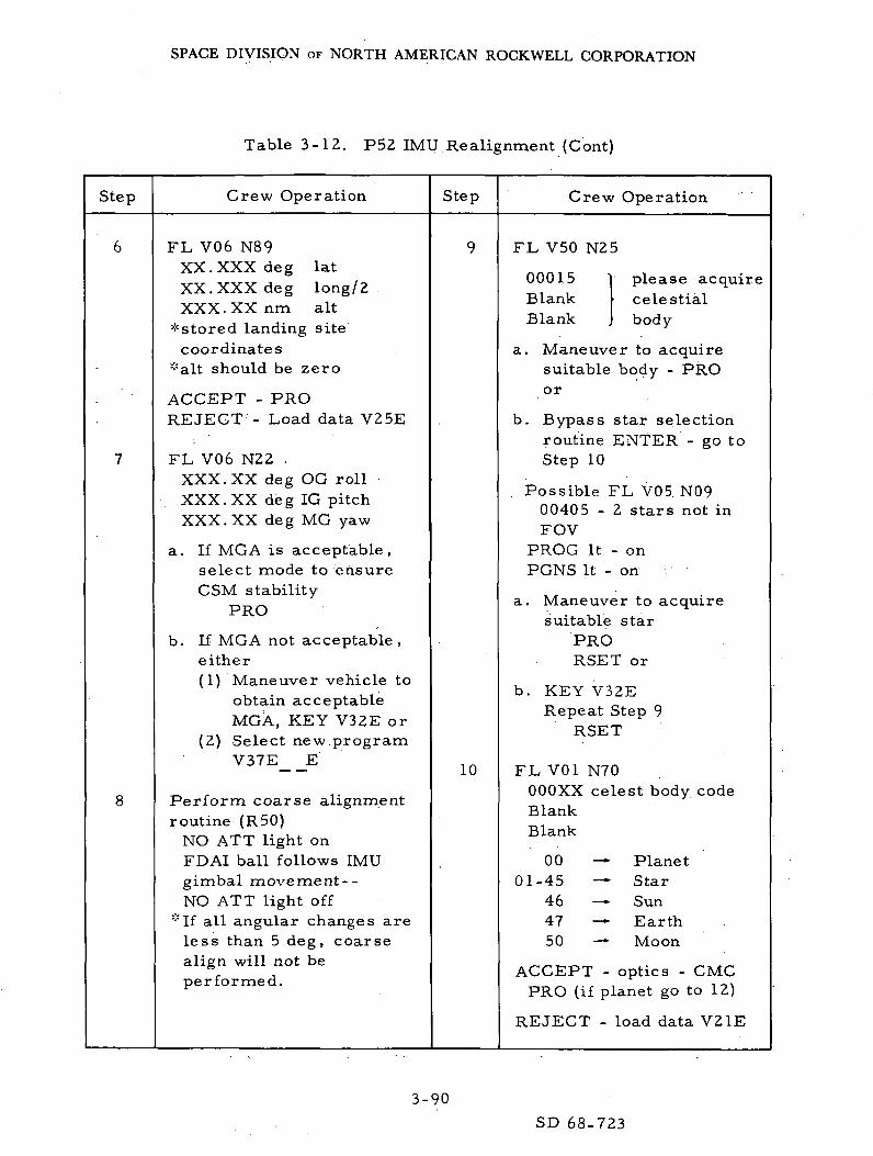
SPACE DIVISION OF NORTH AMERICAN ROCKWELL CORPORATION
Table 3-12. P52 IMU Realignment (Cont)
Step Crew Operation Step Crew Operation
FL V06 N89XX. XXX deg latXX. XXX deg long/2XXX. XX nm alt
* stored landing sitecoordinates
*alt should be zero
ACCEPT - PROREJECT - Load data V25E
FL V06.N22 .XXX. XX deg OG rollXXX. XX deg IG pitchXXX. XX deg MG yaw
a. If MGA is acceptable,select mode to ensureCSM stability
PRO
b. If MGA not acceptable ,either(1) Maneuver vehicle to
obtain acceptableMGA, KEY V32E or
(2) Select new programV37E E
Perform coarse alignmentroutine (R50)
NO ATT light onFDAI ball follows IMUgimbal movement--NO ATT light off
*If all angular changes areless than 5 deg, coarsealign will not beperformed.
10
FL V50 N25
00015BlankBlank
please acquirecelestialbody
a. Maneuver to acquiresuitable body - PROor
b. Bypass star selectionroutine ENTER - go toStep 10
. Possible FL V05. N0900405 - 2 stars not inFOV
PROG It - onPGNS It - on
a. Maneuver to acquiresuitable star
PRORSET or
b. KEY V32ERepeat Step 9
RSET
FL V01 N70OOOXX celest body codeBlankBlank
0001-45
464750
PlanetStarSunEarthMoon
ACCEPT - optics - CMCPRO (if planet go to 12)
REJECT - load data V21E
3-90
SD 68-723

SPACE DIVISION OF NORTH AMERICAN ROCKWELL CORPORATION
Table 3-12. P52 IMU Realignment (Cont)
Step Crew Operation Step Crew Operation
11 FL V06 N88For planet load only
ACCEPT - PRO, REJECTKEY V25E and load
12 Perform auto opticspositioning (R52)*If OCDU angles not dis-played - VI6 N92E
*Possible FL V05 N09404 ~ TA > 90 deg
a. Select control mode andmaneuver to reduce TA
b. or key V34E
*Possible FL V05 N09407 ~ TA> 50 deg
KEY RELEASE andmaneuver to reduce TA
*When marks are desired,optic mode - manual
13 FL V51 (please mark)Mark (on target)
14 FL V50 N2500016 (term, marks)
ACCEPT - PROREJECT - mark reject
15 FL V01 N71OOOXX target code
ACCEPT - PROREJECT - V21E and load
desired code
Repeat steps 10 through 15for Target 2
16
17
18
19
20
21
Planet onlyFL V06 N88
ACCEPT - PRO
FL V06 N05
XXX. XX degsightingangledifference
ACCEPT - PROREJECT - V32E (go to
Step 19)
FL V06 N93 (Agyro angles)X, Y, Z, XX. XXX deg
ACCEPT - PROREJECT - V32E
FL V50 N25
00014 fine align check
ACCEPT - PRO returnto Step 9
REJECT - ENTR
FL V37
OOE
Optics Zero - Zero
3-91SD 68-723

SPACE DIVISION OF NORTH AMERICAN ROCKWELL CORPORATION
Table 3-13. P53 Backup IMU Orientation Determination
Step Crew Operation Step Crew Operation
.1
2
CMC - onISS - onSCS - on
CMC ATT - IMUCOAS - calibrated
Select total attitude display
KEY V37E 53E
FL V50 N2500015 (acquire target)
V16N20 in LEB to monitorfor impending gimbal lock
*to avoid impending gimballock key ENTER and go to"b" below
a. Select desired attitudecontrol mode, maneuverto acquire target ifnecessary
PRO
b. To coarse align IMU toSC axis ENTR (whenattitude acceptable)
V41 N22 (coarse align)R ,P ,Y - 000.00 degNO ATT light - on, then
offReturn to Step 3
10
FL V06 N92.
SA XXX. XX degTA XX. XXX deg
ACCEPT - PROREJECT - V24E load
desired SA and TA(nominal SA = 000 .00 ,TA = 57.470)
FL V53 (please.mark)
RHC - center target inCOAS reticle (MIN IMPrecommended)
ENTR
FL V50 N2500016 (terminate marks)
ACCEPT - PROREJECT - ENTR and .
return to 5
FL V01 N71OOOXX (target code)
ACCEPT - PROREJECT - V21E and load,
return to Step 4 fortarget 2
FL V06 N88 (planet only)
x .y .z PL .XXXXXACCEPT - PRO
.REJECT - V25E and load
FL V06 N05XXX. XX deg star angledifference
ACCEPT - PROREJECT - V32E and
return to Step 3
FL V37 KEY XXE
3-92SD 68-723
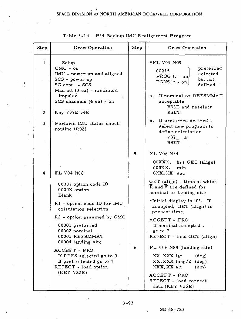
SPACE DIVISION OF NORTH AMERICAN ROCKWELL CORPORATION
Table 3-14. P54 Backup IMU Realignment Program
Step Crew Operation Step Crew Operation
2
3
SetupCMC - onIMU - power up and alignedSCS - power upSC cont. - SCSMan att (3 ea) - minimum
impul s eSCS channels (4 ea) - on
Key V37E 54E
Perform IMU status checkroutine fR02)
FL V04 N06
00001 option code IDOOOOX optionBlank
Rl - option code ID for IMUorientation selection
R2 - option assumed by CMC
00001 preferred00002 nominal00003 REFSMMAT00004 landing site
ACCEPT - PROIf REFS selected go to 9If pref selected go to 7
REJECT - load option(KEY V22E)
*FL V05 N09
00215PROG It - onPGNS It - on
preferredselectedbut notdefined
a. If nominal or REFSMMATacceptable
V32E and reselectRSET
b. If preferred desired -select new program todefine orientation
V37 ERSET
FL V06 N34
OOXXX.oooxx.oxx.xx
hrs GET (align)minsec
GET (align) - time at whichR and V are defined fornominal or landing site
* Initial display is '0 ' . Ifaccepted, GET (align) ispresent time.
ACCEPT - PROIf nominal accepted: .go to 7
REJECT - load GET (align)
FL V06 N89 (landing site)
XX. XXX lat (deg)XX. XXX long/2 (deg)XXX. XX alt (nm)
ACCEPT - PROREJECT - load correct
data (KEY V25E)
3-93
SD 68-723
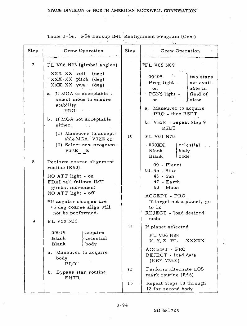
SPACE DIVISION OF NORTH AMERICAN ROCKWELL CORPORATION
Table 3-14. P54 Backup IMU Realignment Program (Cont)
Step Crew Operation Step Crew Operation
FL V06 N22 (gimbal angles)
XXX. XX roll (deg)XXX. XX pitch (deg)XXX. XX yaw (deg)
a. If MGA is acceptable -select mode to ensurestability
PRO
b. If MGA not acceptableeither . . ,
(1) Maneuver to accept-able MGA, V32E or
(2) Select new program .V37E E
Perform coarse alignmentroutine (R50)
NO ATT light - onFDAI ball follows IMU
gimbal movementNO ATT light - off
*If angular changes are<5 deg coarse align will
not be performed.
FL V50 N25
00015BlankBlank
acquirecelestialbody
a. Maneuver to acquirebody
PRO
b. Bypass star routineENTR
10
11
12
13
*FL V05 N09
00405Prog light -
onPGNS light
on
two starsnot avail-able infield ofview
a. Maneuver to acquirePRO - then'RSET
b. V32E - repeat Step 9RSET
FL V01 N70
OOOXXBlankBlank
celestialbodycode
00 - Planet01-45 - Star
46 - Sun47 - Earth50 - Moon
ACCEPT - PROIf target not a planet, goto 12
REJECT - load desiredcode
If planet selected
FL V06 N88X, Y, Z PL .XXXXX
ACCEPT - PROREJECT - load data
(KEY V25E)
Perform alternate LOSmark routine (R56)
Repeat Steps 10 through12 for second body
3-94
SD 68-723

SPACE DIVISION OF NORTH AMERICAN ROCKWELL CORPORATION
Table 3-14. P54 Backup IMU Realignment Program (Cont)
Step
14
15
Crew Operation
Perform sighting displayroutine (R54)
*If sighting results wererejected (V32E) - go toStep 16
Perform gyro torquingroutine (R55)
Step
16
17
Crew Operation
FL V50 N25
00014 PleaseBlank performBlank ) fine align
ACCEPT - PROreturn to Step 9
REJECT - ENTR
Perform programtermination routine (ROO)
FL V37KEY XXE
3-95SD 68-723

SPACE DIVISION OF NORTH AMERICAN ROCKWELL CORPORATION
<U
10)
^C*
UCO
G
OJ
"G
£G&0
-rH
*^1
•in
'V
ntH
^c ad d ~^ « ccu to .;3
.§ ° 1H 5.
cuT3o2o
'coU
to
O
W
tl3
£ ^£H CQ
2O "Tj
ft 1go'Z,
co
• H
rd
^jbo
rj~j
C
oU-JH
O
• -Mcd
"S
'•-i
. o* ocu Q
Is °
T3 >-,
s S0 ^|
a ^
c O
rt S
cIH
pqcd
0 0m ro
4-» 4J ^^n) cu aj a)
a £ c 2n) d n! d
g g" Eg1
to a S co c! SU 'd u U :d °CO K rt CO R rt
M ' ' Li0 0r1 co J-i to« s • s s5 d f ^M CO Q m
1 1
(M CNJin • m^-T r-T
m mft ft
S Sto to0 U
f^ s
J ij
TJ T3CU CU
S-i ' ' hcu cu
"S ' ' *SIH VHft ' ' ft
1 '
1 1
-H -<
rt fM
in Oi — 1 CO
if -- ±f --nj cu nj cu
c ^3 c 2 .a d d dfi CL, c a, g fc g1 -H ^-1 1 .rH t— 1
CU CUto c u to n oO '2 o U "2 oto c ni co n ni
•5 o
be^ c - '0 3 gfn m " ^i^ 0) T) ««. 0 - C "Vi-, n o M ±;i g % g ^M tn to ,2 "d
| |
fN] fM
LO ID
ft ft
S SCO CO
O O
2 r^jJ i-J
"T3 - 13cu cu^ ^
cu cucu cu"
ft • A
i i
i i
~H (M
CO ^
. c• I-)
go o o o LOro 00 f-i Is" ^
^ «N ^
O
4J* ^J* ^^ 4-> . •*-> ^
c d o j c i j < D o J ( U r t a j
rtp rt? rt3 rtSS O- c! P-i CO- CO-
g R c c g H g •t-t M >H . M
I -H i— 1 1 -M i-H 1 'H _ 1 > 'H ^
Qj D <U rH *^
o -3 u u -3 o o '2 o u •? ot O K " ! t O f i r d t o f i r t t O f i f S
. . . ^ • ^O O O O* - < c o ^ t n ^ c o ^ t n
S S Ss i s S J . g.- j^i D P t > ^ H D ^S o S o ' '2 o ' 2 oK H C O K ^ C O ^ H t O H H W
LD -
C*V ^t ^ ^in in in mA A a, A
(Min
~H" (M (>0 PO .COin in in in inA A a, A A
S S S S Sto co to c/: coU O U O U
H HTJ < . '<
.5- i 1 - ' "cu co co -H g*£ . h h g -Jn . W W o . a,A Pi PC! £ t>
i i i m in
I . rq pg PO' • o\
r-H fM co ro r*-
0!
§> M A
"i S .s ^ ^ »T3 1 rn 4-> (rtS dJ [rt W -M(U (H 2 O O
ti ft a (^ H
3-96
SD 68-723

SPACE DIVISION OF NORTH AMERICAN ROCKWELL CORPORATION
3. 6 LANDMARK TRACKING
3. 6. 1 Study Objectives
Study objectives are as follows:
1. Verify the operational integrity of the orbital navigation program(P22).
2. Verify the operational integrity of the ground track determinationprogram (P21).
3. Determine ease in locating and identifying landmarks.
4. Determine the time and RCS propellant required to perform thenavigation function.
5. Evaluate landmark tracking in the LM-on configuration.
6. Evaluate the orbit determination capability of the orbital naviga-tion program (P22) for the tracking of known and unknownlandmarks.
7. Provide a data base for postflight analysis.
3. 6. 2 Study Scope
This portion of the study will evaluate the automatic and manual track-ing capability for known landmarks and the manual tracking capability forunknown landmarks. The tracking of landmarks with the CSM configurationwill be performed in the "nominal" sighting a titude. LM-on landmarktracking will be performed using the broadside attitude with respect to theorbital ground track. Other sighting attitudes will be investigated to obtaina comparison with respect to ease of tracking and RCS propellant consump-tion. Tracking of a single landmark and sequential tracking of three ormore landmarks will be simulated. The state vector updates resulting fromprocessing tracking data will be used to evaluate the orbital determinationcapability of the tracking modes. The ground track determination programwill be used during simulation runs to facilitate selection of landmarks.
3-97SD 68-723
SPACE DIVISION OF NORTH AMERICAN ROCKWELL CORPORATION
3. 6. 3 Run Description
Orbital navigation is accomplished by scanning telescope tracking of aknown landmark or by .sextant tracking of an unknown landmark. The naviga-tional measurements are used by the CMC to obtain an estimate of thevehicle's position and velocity. A known landmark is a landmark for whichthe longitude, latitude, and altitude are defined and may be stored in theCMC or entered by -way of the DSKY by the astronaut. An unknown landmarkis a landmark selected by the astronaut because of a recognizable terrainfeature and ease of tracking, but whose coordinates are not defined. Thetracking of a known landmark is further facilitated by the use of the automaticoptics positioning routine, while unknown landmarks must be trackedmanually. Prior to the tracking sequence, the orbital ground track programmay be used to facilitate the selection of known landmarks by computing thelongitude and latitude of the vehicle at selected times during the comingtracking sequence. The detailed procedures for the ground track deter-mination program (P21) and the orbital navigation program (P22) are pre-sented in Tables 3-16 and 3-17, respectively.
3. 6. 4 Run Schedule Synopsis
Table 3-19 presents the schedule of runs that will be used to verifythe orbital navigation program (P22) and the ground track determinationprogram (P21). The runs are classified as to landmark number, trackingoption, control mode, error sources, error values, and simulator runningtime. The landmark numbers presented are symbolic in that two basictracking sequences will be investigated. The landmark F type of sequencewill occur near the highest latitude of the ground track, and the T-typelandmark will be near-equatorial. Tracking -will be performed on both asingle landmark and a sequence of three or more landmarks for F and T types.Landmarks will be designated as known, unknown, or a combination of thetwo for sequential tracking. Runs 1 and 2 will be initiated as circular orbits,and state vector errors of various magnitude will be used to establish a database and a region of convergence so as to evaluate the orbital determinationcapability of P22. The nominal, broadside and selected tracking attitudeswill be employed for these runs. Runs 3 and 4 are designed for the samepurpose as Runs 1 and 2 except that Type T landmarks will be employed.Runs 5 and 6 are scheduled to track, in sequence, three or more landmarksthat are combinations of known and unknown. Run 7 is scheduled to showthe effects of a drifting IMU on the orbit determination process. Pro-gram P21 may be utilized in any of the runs but will be scheduled for use inRuns 5 and 6.
3-98
SD 68-723

SPACE DIVISION OF NORTH AMERICAN ROCKWELL CORPORATION
Table 3-16. P21 Ground Track Determination
Step Crew Operation Step Crew Operation
1
2
CMC - on
Key V37E 21E
FL V04 N06
00002 option codeOOOOX CMC assumed
option
(00001) = CSM(00002) = LM
ACCEPT - PROREJECT - V22E load option
FL V06 N34 (GET lat-long. )
OOXXXOOOXXOXX.XX
hrminsec
ACCEPT - PROREJECT - V25E load time of
lat-long
FL V06 N43
Lat (+N) XXX. XX degLong. (+E) XXX.XX degAlt XXXX. X nm
(alt above launch padradius)
*To increment time-lat-long. by 10 min keyV32E and return toStep 3
PRO (terminates P21)
FL V37 XXE
3-99SD 68-723
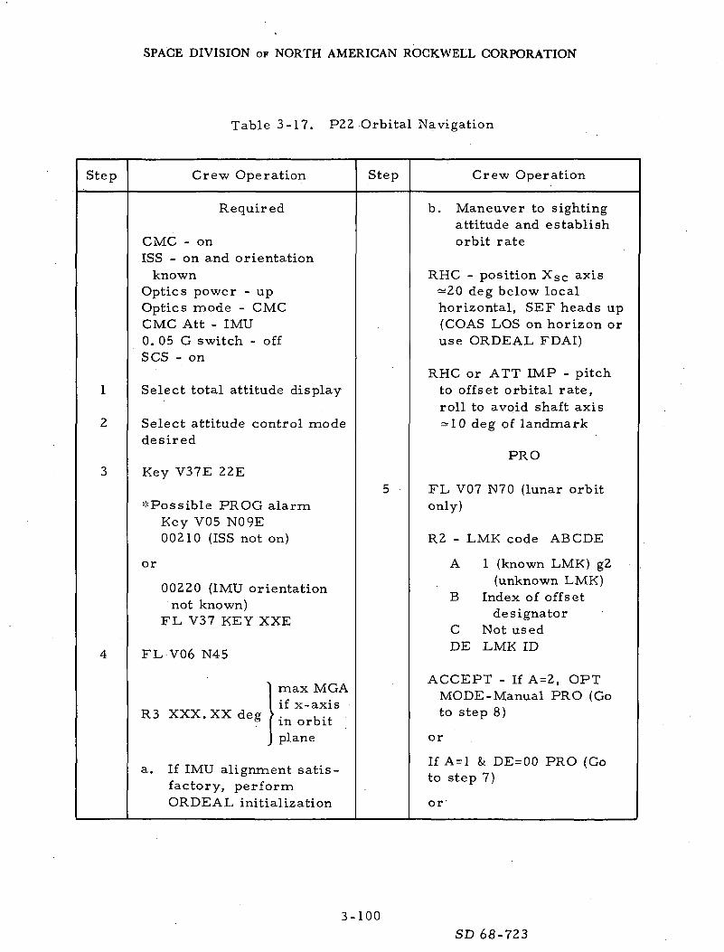
SPACE DIVISION OF NORTH AMERICAN ROCKWELL CORPORATION
Table 3-17. P22 Orbital Navigation
Step Crew Operation Step Crew Operation
1
2
Required
CMC - onISS - on and orientation
knownOptics power - upOptics mode - CMCCMC Att - IMU0. 05 G switch - offSCS - on
Select total attitude display
Select attitude control modedesired
Key V37E 22E
^'Possible PROG alarmKey V05 N09E00210 (ISS not on)
or
00220 (IMU orientationnot known)
FL V37 KEY XXE
FL-V06 N45
R3 XXX. XX deg
max MGAif x-axisin orbitplane
a. If IMU alignment satis-factory, performORDEAL initialization
b. Maneuver to sightingattitude and establishorbit rate
RHC - position Xsc axis^20 deg below localhorizontal, SEF heads up(COAS LOS on horizon oruse ORDEAL FDAI)
RHC or ATT IMP - pitchto offset orbital rate,roll to avoid shaft axis= 10 deg of landmark
PRO
FL V07 N70 (lunar orbitonly)
R2 - LMK code ABCDE
A 1 (known LMK) g2(unknown LMK)
B Index of offsetdesignator
C Not usedDE LMK ID
ACCEPT - If A=2, OPTMODE-Manual PRO (Goto step 8)
or
If A=l & DE = 00 PRO (Goto step 7)
or
3-100
SD 68-723

SPACE DIVISION OF NORTH AMERICAN ROCKWELL CORPORATION
Table 3-17. F22 Orbital Navigation (Cont)
Step
5(cont)
r.
Crew Operation
If A=l and DE=00 PRO
-"Possible PROG alarm(00404 and 00407)
REJECT - Key V22E andload desired data
FL V06 N89 (landmarkdata)
Lat (+N)Long. /2 (+E)Alt
XX. XXX degXX. XXX degXXX. XX nm
ACCEPT - PROREJECT - V25E load data
^Possible FL V05 N09000404 (TA > 90 deg)maneuver until opticscan acquire landmark
or V34E (terminatesprogram)(FL V37 XXE)
-"Possible PROG alarm(TA >50 deg)Key V05 N09E
00407Maneuver to reducedesired trunnion angle
V06 N92 (new OCDU angles
SA XXX. XX degTA XX. XXX deg
If not displayed - V16 N92Eto mark optics - MAN
Step Crew Operation
FL V51 (please mark)
ACCEPT - repeat markprocedure or PRO
REJECT - push mark rejectand repeat mark procedure
If 5 marks madeFL V50 N2500016 (terminate marks)ACCEPT - PROREJECT - mark reject
Optics zero (15 sec)Optics mode - CMC
FL V05 N71 (landmarkdata)
R2 - ABCDE
A =1 (known), 2 (unknown)B = offset indicatorC =unusedDE = landmark ID
ACCEPT - PRO, if A = 2(or A = 1 and DE£0) go
to Step 11
REJECT - V22E load data
3-101 SD 68-723

SPACE DIVISION OF NORTH AMERICAN ROCKWELL CORPORATION
Table 3-17. P22 Orbital Navigation (Cont)
Step Crew Operation Step Crew Operation
10
11
12
FL V06 N89 (landmarkcoordinates
Lat XX. XXX degLong. /2 XX. XXX degAlt XXX. XX nm
ACCEPT - PROREJECT - V25E load data
FL V06 N49
AR XXXX. X nmAV XXXX. X fps
ACCEPT - PROREJECT - V32E and in
EO -return to Step 6 or LO -return to Step 5
FL V06 N89
Lat XX. XXX degLong. /2 XX. XXX degAlt XXX. XX nm
ACCEPT - PRO, EO -return to Step 6, LO -Step 5
REJECT - V32E, EO -return to Step 6,LO - Step 5
13 Key V34E (to terminate P22)
FL V37 key XXE
3-102 .SD 68-723

SPACE DIVISION OF NORTH AMERICAN ROCKWELL CORPORATION
COri
rtaV
_, cu —! g j
CO
O MIn 3r-i nj
W >
(0" M0 y
W 0co
r— 1
0 D
0 10
^
ill1UJ H
(-1
1 1rt
d0
a• Hf-,(JCOcuQd
Cd
M
H od Z,3
^ T3 'O M <3R) *" d!_, O --1
h ni J3
_
•H O
"rt ^ c""
-1 Ismi— t
i
cu
OZ,
cuin3aa(-ta3 ' — 'a s
•H (J
w d ^U •£CO K cc
cod .
,M1od
fa
^ '
,O Ufn CO 0
fll «i-l
« n Srt nj -M
I-2 8-P rt M
£ 3 VO T3 (M
•— '
O "H* -W O
(0 I«Hc *""* *^rt rg T3 dd OH « rt
V rt X ^
** .S rt -2 •£ +> •° -* £0 i> o ^
£ >2 Hi ,3 LC ^ 1)
in in in
CO
'S oo ^rt xl 73^ d d"-1 cu rt rt
O in O Oo •>- o o
° 4n ° °^ - •>in (NJ o or-H 1 — 1 I-H , — 1
!i (H l<O O O
o o ocu cu cu
cu cu curt rt rt
CO « CO
1 — 1 1 — 1 1 — 1O (U (U
S O ri O H O0 g U g 0
d nj 3 nJ 3 rt
S (-l (HV r1 y r< y
00 1-t OO M OO• iH .r-t •!-<
d S3 s"3co a co a co aU g 0 g u gCO .S CO .S CO .3
d d d
o o od d - d
0 O O
d "d "s
h h h
curt01 d
^d *-( oco O O
• rt
•2 o °(u -1-4 -i->
"^ o° o™ M 0)
W H >
< CQ Ui — 1 t— 1 i— H
in in m int— 4 I— 1 i— H .— 1
CQ
'x °°rt TJ ^* °^ d T3
«-i ,a d Ej^ IN] O0 ^ , 0 oo o o
- T3 . Om d o-H n) •— ' m
M h M
O O 0
o o ocu cu cu
0) 0) 1) 0)
o (d rt rtS CO CO CO
r-H I— H r-H r-H
CU D <U D
H o c o c o c oo G O g o C o
3 ^ J ^ n J 3 ^ J ^ c d
•rj 'rt 'S 'S
g .2' g .2 S .2 aJ2i d id i 3 i 3
^ .§ co 1 lo .rt oo 1
J, c --J, c J. c _, c
™ 2 - ^ 2 ^ 2 5 2d _g d _g d _g ,d _g
fe fa fa h
£""* T3
o S d no
cu g o 'Soo $ d oti O -ii Scu d d S> A! d n
< PQ Urg ts) (M rg
O
1
cu
O
4)
H °
a^^ cu
i "3C/} Oto gco .ad
•odio
H
4-1,G COrH d
O . O
% ":^rt M -*->
"3* 8." rt «rrt « "O T3 <M
ro
O Or-H r-H
(SIr— t
rj-J ^
d T3
nj Co rt
o oO 0
omrH in
rH rH
O 0
o ocu cu
cu curt rt
CO CO
i— 1 <— I
o> cug ° g °
ll 1-S « S a;a ^ a ^i d i d
co a co a0 g O gCO .rt CO -rt
d d
o od di i0 5"d d
H H
F-C '+4
tfi O
S §ri .
•*•* MW rtj
W M
i
<1 PQro ro
O O O
rg
T) "*d T3rt d
' o rt
o o0 O
om-H m
H (I
o oO 0cu <u
cu cu cud -*-1 -*-1Q rt rt,5 co co
cu cu cuS o c o c o
y C o C o3 dj 5 rt -^ rt
• rt ^^ «rt °a .rt °a
d d d.rt cu .rt cu ." cua J2 a J2 a ^3i d i d i d
co a co a co a0 g U g U gCO .rt CO -rt CO .S
^ d d d
3 0 3 0 3 0d « d c d c| d | d | -Sr< 3 £ d .< d
H H H
cu
dcu
doo
< PQ•^ - -
1u
CO
rtDO
S
I*O
00
3-103
SD 68-723

SPACE DIVISION OF NORTH AMERICAN ROCKWELL CORPORATION
M
^
60!
_ 4) CT
| g.|
i. in .
£ 3JH "
W >
W
O o^ h
W oCO
'o D
"G °o SU
Landm
ark
Tra
ckin
gO
ption
Xrd
M O
rt
CO
4_)
a~n0to4)Q
c3
4)
H OC 2
01 ">, £ -H Mi-rl frt ^D ^^ C••-> c "~0 C o 3w ^ i o-* ^ U O Q <UQ u a; .H to£ 2 ^ c "S JSP-l +j tn a) c 4J
in un LO. PO ' "O ro
oo oo
*"O "~OC G 'rt n!o oo o
. O 0
o" o"•— ' •-<
M ^0 O0 O0) 0)> >
U QJ fljc •*-* •4~*o jS jS2; 55 S
r— H . 1 i 1
<U (D (USO £ O CH U
U C (j C u
"i rt ~i rt *£ cd£ 6 S
.S a> .S <u -H 4)S ^2 S J2 fi ^2i 3 i 3 i 3
§ 1 § 1 IIc 3 50 5 0c c ^.'S ^ ^
o "o ^ c 3 S-M 4-> /^ k> . fnd 3 X "S ^H C<; < § < i.rj
^ | ^•-• o ^
^ I H
h tT 3 h
0 O 0ro m ro
oo oo"O T3G G!d n!o o0 O0 O
o" o"
•H IH
O 0
o • u4) 4)> >
4) 4) 4)
Q Ctf (d
2 w w
. - H I — i < — I4) D 4!
C O C O C O§ " C o Co
S ^ S o2 ^ cii'c 'c 'G
6 J3 1 J3 ' 1 Jc d i d i d
co ex co ex co ex
81. 8. § 8!
§ S §0 S 0C g ^ « _ _G
O 0 i G c S"S "t! 2 - rt 1-1-; J c G ^ ^^
H c E^ri O ^H
h J H
H H d H"
T3G £
1 -H
^^ o2 ^ 0 )
-l-> >-l m
C -r-l
3 sS hcr. -j 4)<u S x
1/2 C 4>
< CQin in in
< n
m m1—4 . i—t
"
4) <Ua co o2 2;
"•M <4^• i-l -r-(
JH JHT3 T3
^ 5~
si c s§ o Co
i c« s c«'^ 'S"*"* QJ rH QJ
^ S J2r A 3 1 3w ex co ex
« .§ ^ 6
G
0 rtG ' c
v, 'j >
0 2 G
3 rt ^
h h
•*•* *j" '
^ ?,o ^^ (U U <4H QJ
o w u O X
s & £ g > « s"d 1-1 w 8 4) o0 J tl 3 0" d m
•H S 'C M 4) "S dU $ 13 (t > T) IH
<J
r- t-
G•T-l
^ S^ in
<n£j
3
OO
0)
I4)
O•I-C4Jidbo
I
oot— ii
mo
.ntH
3-104
. SD 68-723
SPACE DIVISION OF NORTH AMERICAN ROCKWELL CORPORATION
3.7 SM ABORT
3.7.1 Study Objectives
Study objectives are as follows:
1. Verify efficient and satisfactory crew operational proceduresfor each SM abort mode.
2. Evaluate the system rate damping capability for tumbling aborts.
3. Evaluate the adequacy of the time of free fall (tff) and maximumg (Gxnax) limit lines for Mode II aborts.
4. Evaluate the adequacy of the specified prethrust coast time forMode III and IV aborts.
5. Determine SPS AV maneuver execution errors for tumbling aborts(Modes III and IV).
6. Evaluate abort criteria and mode selection logic.
7. Determine RCS and SPS propellant requirements for tumblingaborts.
8. Evaluate the effectiveness of the land avoidance criteria forMode III aborts.
9. Evaluate the effectiveness of Mode III and IV AV maneuvers toachieve the desired terminal conditions.
10. Verify satisfactory operation of related CMC programs.
3.7.2 Study Scope
The SM abort study will evaluate the three abort modes (II, III and IV)that cover the phases of the launch from LES jettison to orbit insertion. TheMode II and III aborts for which orbit insertion is not achieved will beevaluated through the entry phase. This will be the first mission evaluation
3-105SD 68-723

SPACE DIVISION OF NORTH AMERICAN ROCKWELL CORPORATION
of SM aborts off the Saturn V launch vehicle and with a fully loaded CSM.The basic SM abort philosophy is presented in the flow diagram in
Figure 3-2.
3. 7. 3 Run Description
The major events of the three abort modes are described below.
3.7. 3. 1 Mode II
This mode results in a free fall into the continuous recovery area(Pad + 60 nm to 3350 nm downrange) with a maximum load factor duringentry of 16 g and a minimum of 100 seconds' f ree fall to 300, 000 feet. Thenominal range of time from liftoff for this mode is approximately 185 to630 seconds. The sequence of G&C events is as follows:
1. RCS +X translation and/or SPS rate damping burn
2. Maneuver to CM/SM separation attitude and separate
3. Maneuver to entry attitude
4. Full lifting entry
3. 7. 3. 2 Mode III
This is the least probable abort mode and will be used only ifimmediate return of the spacecraft becomes necessary. This mode is usedfrom approximately 630 seconds after liftoff to orbit insertion. It providessplashdown in the discrete recovery area 3350 nm downrange of the padwith the following sequence of events:
1. RCS +X translation and possibly an SPS rate damping burn
2. Maneuver to the retrograde thrusting attitude and performance ofrequired AV
3. Maneuver to CM/SM separation attitude and separation
4. Maneuver to entry attitude
5. Entry into discrete landing area
3-106
SD 68-723
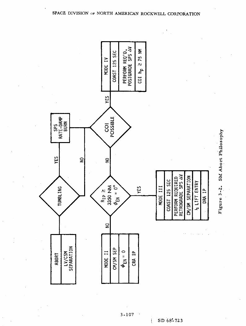
SPACE DIVISION OF NORTH AMERICAN ROCKWELL CORPORATION
t— »
IIIIllj
0o
oLUCO
LOCM
H-CO
^tr^"
^- oo
LU OOQi
LUS QQ£ <O Q:Lu CDce. i— iLU COQ. O
0.
2:
in
Al
Q..c
1— 10O
oo
OOLU
a:ocaef.
CO
O.LU00
o
I-HI—I
LUQO
Q.LUOO
00
O
0
IIzLU
-o-
Q.
2O
ooLU i— i
I-H
LU0OSI
0LUooLOesj
•rCO
O
>
LU o: coi-< O_•=> coLU LUQ£ O'
xS CDO OLU 0£o: i—LU LU0. 0£
z
EPAR
ATIO
CO
• -00
o
C£I—
LU
I—LuI-H
i«J
Aw
0.HH
1Q
oCOod
•sO '
CO
(VJt '
to
CuD.1-1
En
3-107SD 68-723
SPACE DIVISION OF NORTH AMERICAN ROCKWELL CORPORATION
3. 7. 3. 3 Mode IV
From GET of 600 seconds to orbit insertion, the capability existsfor contingency orbit insertion. The following sequence of events isplanned.
1. RCS +X TRANSLATION and possibly an SPS rate damping burn
2. Maneuver to the posigrade thrusting attitude and performance ofrequired AV to achieve an initial orbit with a minimum perigeealtitude of 75 nm.
3. A burn at apogee to obtain the desired orbit
An example of a Mode IV abort is given in Table 3-19.
3.7.4 Run Schedule Synopsis
The SM abort study phase will evaluate the abort capability fromvarious points throughout the launch phase from LES jettison to orbitinsertion. Various failure conditions during the abort will be investigated;failures •will include loss of internal attitude reference, loss of voicecommunications, and CMC failure. The run schedule synopsis is presentedin Table 3-20.
3-108SD 68-723

SPACE DIVISION OF NORTH AMERICAN ROCKWELL CORPORATION
Table 3-19. Mode IV SPS Abort
Event TimeStep (sec) Crew Procedure
CMC - on (required)ISS - on (required)SCS - on (required)CMC ATT - IMULOGIC BUS 3 - on (up).05 g - OFFBMAG MODE - RATE 1FDAI SCALE - 50/15FDAI SEL - 1/2RATE - HIGHATT DBD - MAXLIMIT CYCLE - OFFDIRECT RCS - on (up)RCS CHANNELS (4) - ASC CONT - SCSAV THRUST - OFFSPS THRUST - NORMALLV/SPS IND - SII/SIVBRCS CMD - OFFSCS TVC - AUTOTVC GMBL DR - AUTOSPS GMBL MOT (4) - onEMS AV IND - 3000. 0 fpsGDC aligned to IMUMAN ATT - RATE CMD/RSI align to 0 deg
EMS FUNC - AVEMS MODE - STDBYRCS TRNFR - SMEvent timer - 00:03SPS GMBL ind settings
6 et =.
6 t =.
.deg.
-deg.
00:03 Computer run initiated following booster separation.
3-109SD 68-723

SPACE DIVISION,OF NORTH AMERICAN ROCKWELL CORPORATION
Table 3-19. Mode IV SPS Abort (Cont)
Step
1
2
3
4
5
6
7
8
Event Time(sec)
00:03. 8
00:04
00:24
Crew Procedure
Event time reset and counting up
EVNT TMR RSET - RESETEVNT TMR STRT - START
DIRECT ULLAGE - push
RCS CMD - on
LV/SPS IND SII/SIVB - GPI
THC - center and +X translationDIRECT ULL rel
Monitor spacecraft rates
Key V37EKey 47 ENTR(30 sec for display to appear)
Terminate +X translation
Key V16 N50 E
SPLASH ERROR . _ n. mi.
HP ._n.mi .
TFF B min - sec
Maneuver to insertion attitude
R 180 degP 350 degY 0 deg
Obtain insertion update
3-110SD 68-723

SPACE DIVISION OF NORTH AMERICAN ROCKWELL CORPORATION
Table 3-19. Mode IV SPS Abort (Cont)
Step
9
10
11
12
13
14
15
16
17
18
Event Time(sec)
120
135
173
Crew Procedure
BMAG MODE (3) - ATT 1 RATE 2
Verify SPS GMBL ind (2) = SPS GMBL tw (2)settings
6 i | i f = deg
EMS MODE - AUTO
Start Ullage
AV THRUST (2) - NORMAL
SPS THRUST - DIRECT ON
Terminate ullage - IGN +1 sec
AV ind = 1950 fps (HP ^75 nm)
AV THRUST (2) - OFF
EMS MODE - STBYEMS AV ind 1884 fps
SECO +40 secStatus from ground
3-111SD 68-723

SPACE DIVISION OF NORTH AMERICAN ROCKWELL CORPORATION
Table 3-20. SM Abort Run Schedule Synopsis
RunNo.
1
2
3
4
5
6
7
8
9
10
11
12
Mode
II
II
II
III
III
III
III
IV
IV
IV
IV
IV
Description of Run
Min. tff HighLV/CSM Rates
Max. G, HighLV/CSM Rates
End of Mode IIHigh LV/CSM Rates
Early Mode IIINominal LV/CSM Rates
Early Mode IIINominal LV/CSM Rates
Late Mode IIINominal LV/CSM Rates
Late Mode IIINominal LV/CSM Rates
Mode II/IV CrossoverNominal L/V CSM Rates
Mode II/IV CrossoverNominal LV/CSM Rates
Mode II/IV CrossoverHigh LV/CSM Rates
Mode II/IV CrossoverHigh LV/CSM Rates
Mid Mode IVNominal LV/CSM Rates
Delta-VReqm't(FPS)
0
0
0
- 400
~ 400
-1500
-1500
-2000
-2000
-200.0
~ 2000
~ 1000
Source ofCrew Information
Ground
Ground
Ground
Ground
CMC
Ground
CMC
Ground
CMC
Ground
CMC
Ground
Numberof Runs
1
1
1
1
1
1
1
1
1
1
1
1
3-112SD 68-723

SPACE DIVISION OF NORTH AMERICAN ROCKWELL CORPORATION
Table 3-20. SM Abort Run Schedule Synopsis (Cont)
RunNo.
13
14
15
16
17
Mode
IV
IV
IV
IV
IV
Description of Run
Mid Mode IVNominal LV/CSM Rates
Late Mode IVNominal LV/CSM Rates
Late Mode IVNominal LV/CSM Rates
Late Mode IVHigh LV/CSM Rates
Late Mode IVHigh LV/CSM Rates
Delta-VReqm't(FPS)
~1000
-100
-100
^100
-100
Source ofCrew Information
CMC
Ground
CMC
Ground
CMC
Numberof Runs
.1
1
1
1
1
17 RunsTotal
3.8 RCS DEORBIT
3.8.1 Study Objectives
Study objectives are as follows:
1. To establish a data base for mission planning and postflightanalysis
2. To verify RCS deorbit procedure compatibility with the COLOSSUSprogram and the SC 103 Main Control & Display Panel configuration
3. To verify RCS propellant requirements and maneuver efficienciesassociated with various procedures and failure modes and to obtaindata to define the RCS propellant/mission redlines beyond whichsuccessful RCS deorbits cannot be achieved.
3-113
SD 68-723
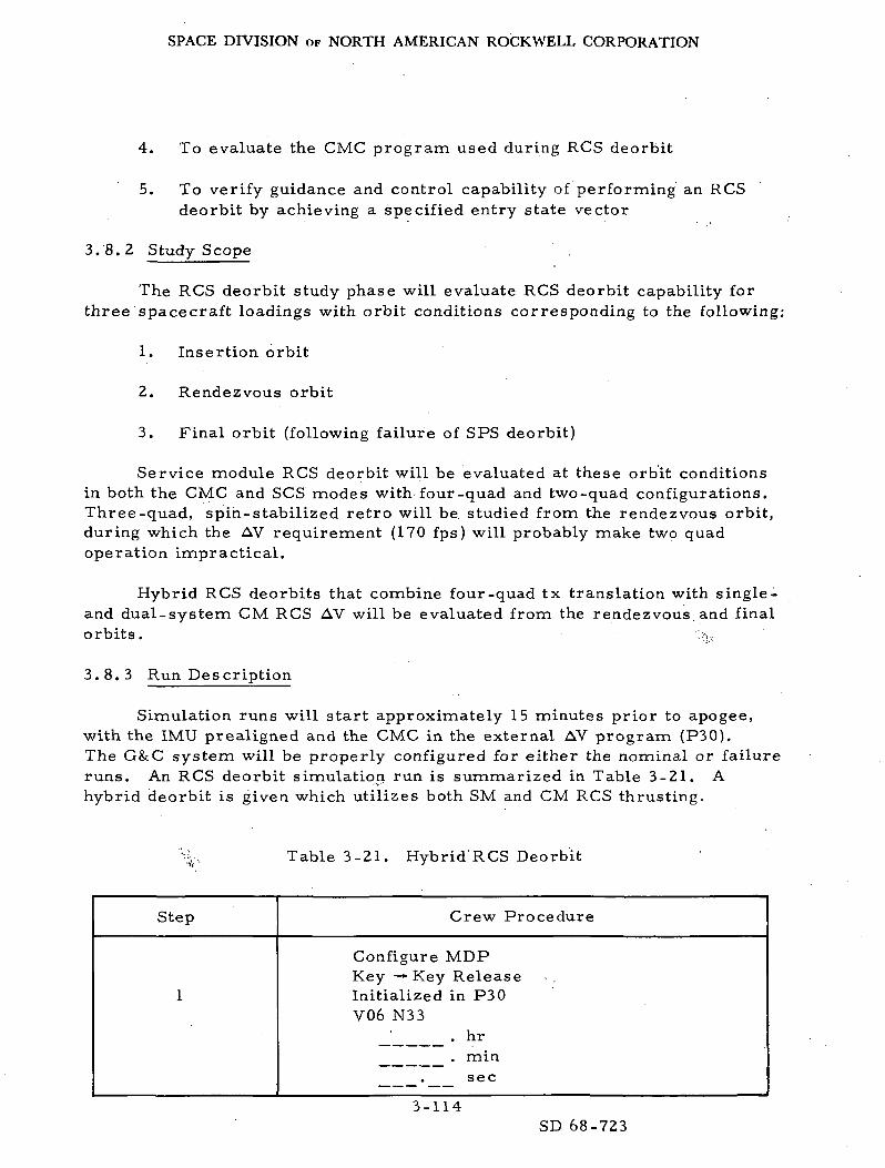
SPACE DIVISION OF NORTH AMERICAN ROCKWELL CORPORATION
4. To evaluate the CMC program used during RCS deorbit
5. To verify guidance and control capability of performing an RCSdeorbit by achieving a specified entry state vector
3.8.2 Study Scope
The RCS deorbit study phase will evaluate RCS deorbit capability forthree spacecraft loadings with orbit conditions corresponding to the following:
1. Insertion orbit
2. Rendezvous orbit
3. Final orbit (following failure of SPS deorbit)
Service module RCS deorbit will be evaluated at these orbit conditionsin both the CMC and SCS modes with four-quad and two-quad configurations.Three-quad, spin-stabilized retro will be. studied from the rendezvous orbit,during which the AV requirement (170 fps) will probably make two quadoperation impractical.
Hybrid RCS deorbits that combine four-quad tx translation with single-and dual-system CM RCS AV will be evaluated from the rendezvous, and finalorbits. • >.,
3.8.3 Run Description
Simulation runs will start approximately 15 minutes prior to apogee,with the IMU prealigned and the CMC in the external AV program (P30).The G&C system will be properly configured for either the nominal or failureruns. An RCS deorbit simulation run is summarized in Table 3-21. Ahybrid deorbit is given which utilizes both SM and CM RCS thrusting.
Table 3-21. Hybrid RCS Deorbit
Step Crew Procedure
Configure MDPKey —Key ReleaseInitialized in P30V06 N33
. hr
. minsec
3-114SD 68-723
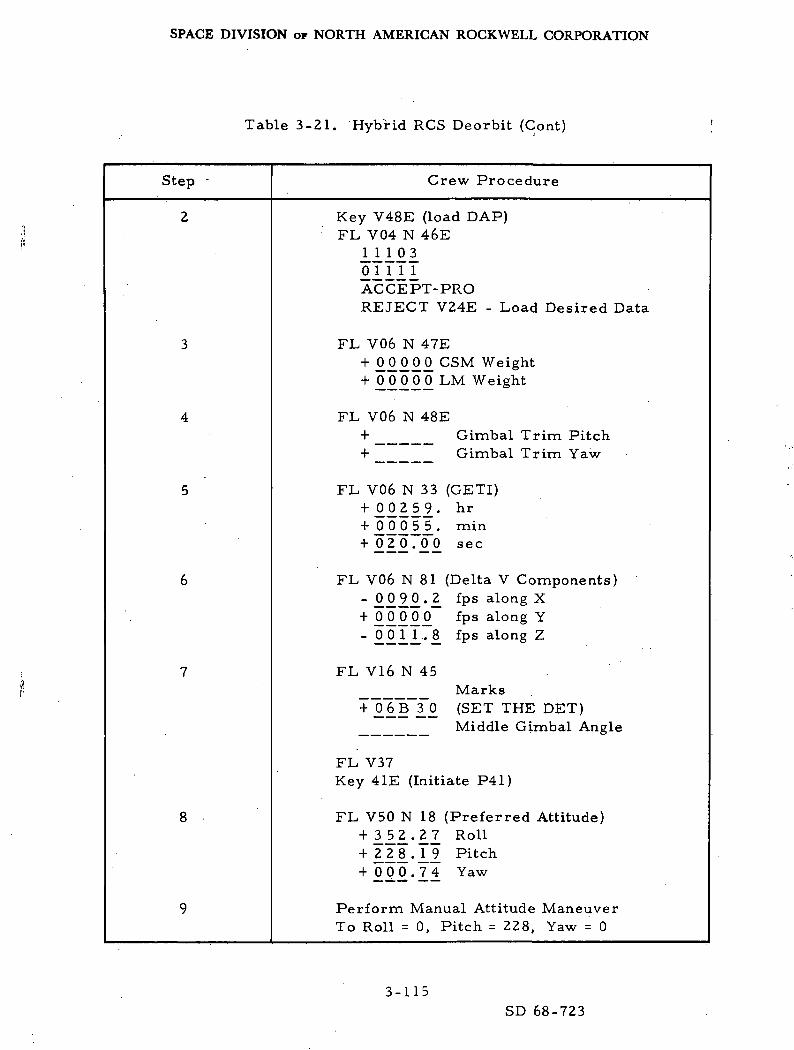
SPACE DIVISION OF NORTH AMERICAN ROCKWELL CORPORATION
Table 3-21. Hybrid RCS Deorbit (Cont)
Step Crew Procedure
Key V48E (load DAP)FL V04 N 46E
III212IIIIACCEPT-PROREJECT V24E - Load Desired Data
FL V06 N 47E
+ 22222 CSM Weight+ 22222 LM Weight
FL V06 N 48E+ Gimbal Trim Pitch+ Gimbal Trim Yaw
FL V06 N 33 (GETI)
+ 22112- hr
+ 22211- min
+ 212-22 sec
FL V06 N 81 (Delta V Components)
- 2222-1 fPs along x
+ 0 0 0 0 0 fps along Y
- 2211-^. fPs alon§ z
FL V16 N 45Marks
+ 2TB~12 (SET THE DET)Middle Gimbal Angle
FL V37Key 41E (Initiate P41)
FL V50 N 18 (Preferred Attitude)+ ill-11 Ro11
+ lli-Il Pitch+ 222-11 Yaw
Perform Manual Attitude ManeuverTo Roll = 0, Pitch = 228, Yaw = 0
3-115SD 68-723

SPACE DIVISION OF NORTH AMERICAN ROCKWELL CORPORATION
Table 3-21. Hybrid RCS Deorbit (Cont)
Step Crew Procedure
10
11
12
13
14
15
16
17
18
19
20
Key V16 N81E (Delta V Components]
-.P. 2 1 0. • 1+ _ O Q _ 0 , O Q _
-2 2 11 • £Key V48E (load DAP)
FL V04 N461110.3.
21111
FL V06 N47+2_1 II 2. CM Weight
0_ £ 0_ 0 0 LM Weight
FL V06 N47
P trimY trim
Key V46E (activate DAP)
S/C Control to CMCCMC AUTOBMAGS ATT 1 Rate 2
Key Proceed (Auto attitude trim)
EMS Function - V set: set V 41. 0 fpsEMS Function V: ATT D. B. min: Rate-Low:RHC, THC armed: LIM cycle off:EMS Mode - AUTO
FL V50 N18 (preferred attitude)
+2 9. 2 £ 2 R
+fL i 8^. 11 P
+°_ 2.2 2 £ Y
GETI minus 35 sec DSKY blanks
3-116SD 68-723

SPACE DIVISION OF NORTH AMERICAN ROCKWELL CORPORATION
Table 3-21. Hybrid RCS Deorbit (Cont)
Step Crew Procedure
21
22
23
24
25
26
27
28
29
GETI minus 30 sec
FL V06 N85
+22112 VGX
+22222 VGY
+ 0 0 0 0 0 V G Z
When DET 00 BOO startSM RCS AV - Monitor EMS AV
V82 E
FL VI6 N44
+ Apogee+ Perigee+ TFF ' ' '
Burn complete; EMS AV = 0HP =
SC control - SCS; CM/SM Sep;RCS transfer - CM; Rate high
Manual maneuver to CM retro
Desired ballR + 2 2 2 - 2 2 DEGP +! 1.5. J) .0 DEC
Y + 2 2 2 - 2 2 DEC
One minute after completion ofSM AV, begin CM AV
MAN ATT PITCH, ACCEL CMD
Begin CM AVRHC 1 - Initialize continuous neg pitchRHC 2 - Pulse plus pitch to maintain
attitude in pitch axisMonitor Hp on DSKY
Discontinue CM AV when Hp = 37. 0 N. M
End of run
3-117SD 68-723

SPACE DIVISION OF NORTH AMERICAN ROCKWELL CORPORATION
3. 8. 4 Run Schedule Synopsis
The RCS deorbit study, consisting of nominal and failure modes ofSM RCS deorbit and hybrid deorbit, will be conducted at three points of theplanned mission. The selection of initial conditions, grouping of runs, andrelated rationale are summarized in Table 3-22.
Table 3-22. RCS Deorbit Conditions and Rationale
Orbit Type of Run Rationale
Insertion
Rendezvous
Final
SM RCS deorbit,nominal and failure modes
SM RCS, hybridnominal modes
SM RCS, hybridnominal and failure modes
Duty cycles for maximum SCloading
Maximum retro velocity required,intermediate SC loading
Duty cycles for minimum SCloading; minimum retro velocityrequired
The run schedule synopsis for SM RCS deorbit and hybrid deorbitare presented in Tables 3-23 and 3-24.
3.9 MCC/ME 103 JOINT SIMULATION
The study objectives, scope, run definition, and run schedule aredetermined by the Flight Control Division of MSC. It is NR's understandingthat the following maneuvers will be accomplished during the MCC/ME 103joint simulation:
1. SPS Burn 1
2. SPS Burn's 1 and 2
3. SPS Burn 4
4. L/M Rescue - CSM Active Rendezvous .
5. SPS Burns 5 and 6
6. G&N SPS Deorbit
3-118
SD 68-723

SPACE DIVISION OF NORTH AMERICAN ROCKWELL CORPORATION
co ~
-pj C
21Q
o 2C
o ^rO ^a rt
W
> -o< 0)
2 '3-u cr0) <U
rt rt
T3
(U3cr'cXuUH
0)IH
_3
rt
.rt tt
"£ ^
0 £
C *3 £?« H
o o o o oro ro ro INI in
O O O
QJ O QJ(H ^H -i
V -C T3 T3 M* C C C in£ W W W ro
o o o o oro ro ro ro r—
U CO U CO °S [J S (J SU co U co O
-f + + 4- +
T3 ^3 TJ T3 T3rt rt rt rt rt
cr cr cr cr CTi i i i i
4) QJ 'O T3 Q^C C rt rt CO O 3 3 O^ z a a z
ro OO ro
ro OO - ro
^H ro ro - in
C
S •-J
o i n i n o o o ° nm s O v O r o r o i n ^ L !
G3 <— tt ^
Q
O O O o O O^ *H J^ >H .. t.
GJ GJ <u aj a) (uJH t( rt t-i (H t.
'S W "2 "2 "o tj 13£ ir. C C C C c
W ro H W H H H
o oo oo oo oo o oor- o o o o r- o
4-1
ri U rn U rn « °O J "^4 C/J ^-J CO f, ^
U & O ^ U -H ^co U co O co P U -
-?<uSI
X X X X X X^w+ + 4- 4- 4- 4 - r t *
'O Td T3 T3 T3 'C (0 T3rt (d cd rt rt rt_,rtcr cr cr cr cr cr 'o. cr11 1 1 1 1 1 yj 1
<U ' <U 0) TJ 'O rd "UC C C rt rt «J CO O O 3 3 2 O2 ^ z a a a *
om ro m
o o o^ ro ~^~ro — • ro
\o t — oo 0s o «— < ro
4)
-3
UCO
IVt'Oa>
Q
U
co;i
V•—I
id
3-119
SD 68-723

SPACE DIVISION OF NORTH AMERICAN ROCKWELL CORPORATION
Du
rati
on
(min
)
O tn
Q (— <
CH P*l
W
Re
tro
AV
:SM
/CM
Tech
niq
ue
<: F
ail
ure
Orb
it
C <u
o o in o o inm r\j so r\r m o -
(M
OO OO OO OO PO O^H
o o oh . ^ £a ) a j < i > .M • ' L< t-t
m • "a m "rt ' C.00 H co H W - _ .
m . in in
in. . in •-- •*-- inOO OO CO CO OJp— H I 1 VO vO ' 1
r£ r£ f-^ l-£ ' r^M
U O U U O
Pk CU Si £ S
U U
r "\ C f -\ G " K
s ^ " s « " SC D 03 C 0) OJ i-M0 C >, 0 fi >, CO^ O co *&' O w Q
0 O 0.00 oo in m oof— 1 i-H 0s C^ """
O O O O OO O 0 0 1 — 1 . 1 — 1 O O^H r-l f\] OO i— 1
i— i' ~ oo ~ oo • • ^ -in
. ena,oa
QJ.
UCO
c-EJ.."
O0)
Q;00U
>sffi
(M
CO
0)
3-120
SD 68-723

SPACE DIVISION OF NORTH AMERICAN ROCKWELL CORPORATION
7. SCS SPS Deorbit
8. G&N SM RCS Deorbit
9. SCS SM RCS Deorbit
10. G&N Hybrid Deorbit
The initial conditions required and a daily run schedule covering athree day period will be provided by MSC at a later date.
The resultant data will be analyzed by NR personnel and reported onalong with the results of the other study phases.
3. 10 FINAL SOFTWARE VERIFICATION TESTS (FSVT)
The final software verification tests objective is to verify as many ofthe CMC software programs for flight as is practical. To achieve this end,the most recent trajectory data, usually the Operational Trajectory, AOHprocedures, CMC Colossus Tape Revision, and flight plan information willbe utilized in these tests. The exact procedures, and detailed runs schedulewill be mutually determined by NR and MSC at a later date.
3-121SD 68-723
SPACE DIVISION OF NORTH AMERICAN ROCKWELL CORPORATION
4. 0 DATA OUTPUT REQUIREMENTS
The data output requirements for this simulation are divided into threecategories: analog, environment, and downlink.
4. 1 ANALOG
The analog data requirements consist of parameters that require con-tinuous recording for transient response analysis as well as real-timemonitoring. This list is composed of parameters computed on the analogcomputers and a few select parameters that are computed on the RTSS andD/A-converted. These analog requirements are defined in Table 4-1.
4. 2 ENVIRONMENT
The environment data requirements consist primarily of trajectory-type parameters that are computed on the RTSS and discretes that representthe configuration of the CM panel switches. The environment recordingrequirements are defined in Table 4-2.
4. 3 DOWNLINK
The downlink data consist of CMC stored information. Five downlinkdata lists exist: (1) powered, (2) coast and align, (3) rendezvous and pre-thrust, (4) entry and update, and (5) program 22 (landmark tracking). Eachlist has a 100-word capability. The downlink requirements for this studyare defined in Table 4-3 for each of the five lists.
4-1
SD 68-723
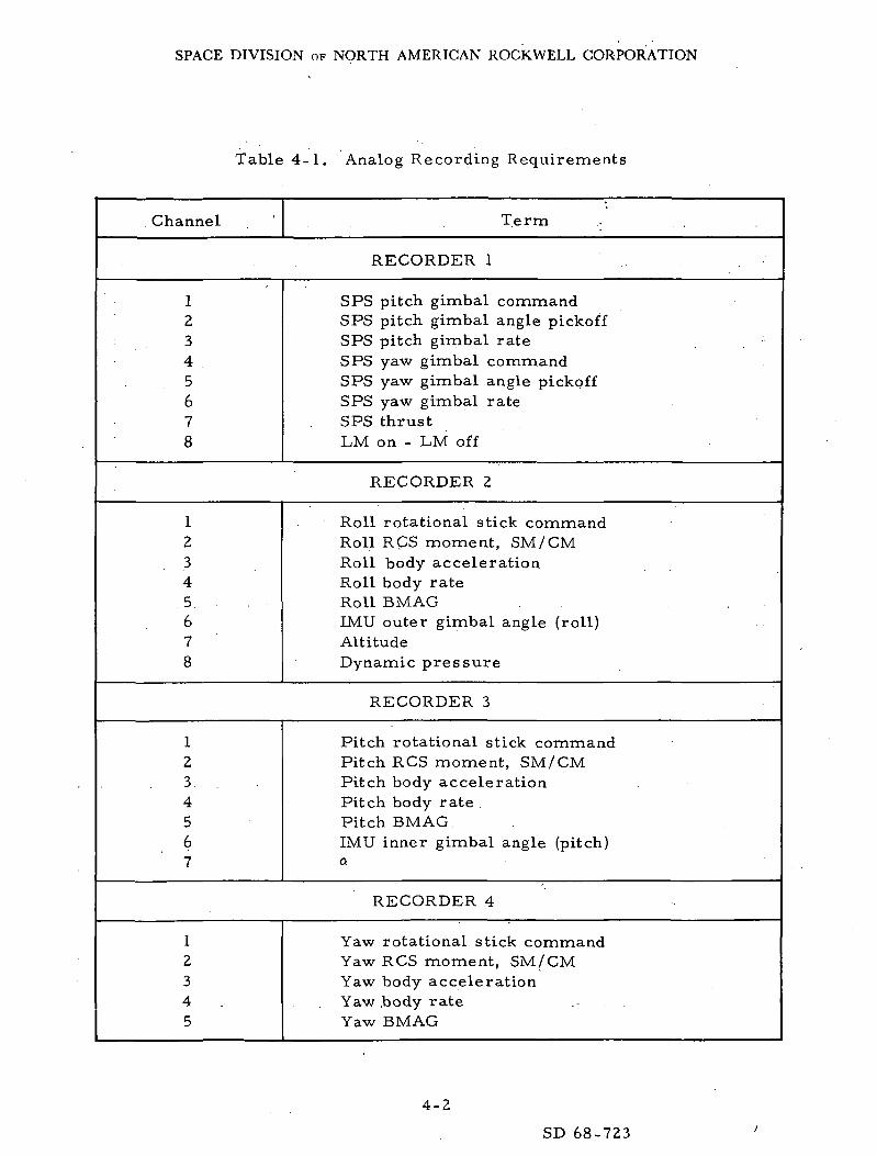
SPACE DIVISION OF NORTH AMERICAN ROCKWELL CORPORATION
Table 4-1. Analog Recording Requirements
Channel Term
RECORDER 1
12345678
SPS pitch gimbal commandSPS pitch gimbal angle pickoffSPS pitch gimbal rateSPS yaw gimbal commandSPS yaw gimbal angle pickoffSPS yaw gimbal rateSPS thrustLM on - LM off
RECORDER 2
1234
.5.678
Roll rotational stick commandRoll RCS moment, SM/CMRoll body accelerationRoll body rateRoll BMAGIMU outer gimbal angle (roll)AltitudeDynamic pressure
RECORDER 3
1234567
Pitch rotational stick commandPitch RCS moment, SM/CMPitch body accelerationPitch body rate .Pitch BMAG.IMU inner gimbal angle (pitch)
RECORDER 4
12345
Yaw rotational stick commandYaw RCS moment, SM/CMYaw body accelerationYaw .body rateYaw BMAG
4-2
SD 68-723

SPACE DIVISION OF NORTH AMERICAN ROCKWELL CORPORATION
Table 4-1. Analog Recording Requirements (Cont)
Channel Term
RECORDER 4 (Cont)
678
IMU middle gimbal angle (yaw)
PGA
RECORDER 5
12345678
Displayed roll rateDisplayed roll attitude errorDisplayed pitch rateDisplayed pitch attitude errorDisplayed yaw rateDisplayed yaw attitude errorScale rate discrete, 50/10Scale rate discrete, 5
RECORDER 8
12345678
Quad A/-rollQuad B/+rollQuad C/pitchQuad D/yaw
/system A/system B
SM total/CM total
SM/CM RCS propellant
RECORDER 9
12345678
A4C4B4D4C3AlBlD3
- A2/- C2/- B2/F9 -- D2/F11- A3/F1 -- C1/F3 -- D1/F5 -- B3/F7 -
SM/CM RCS engines
F12- F10F2F4F8F6
4-3
SD 68-723

SPACE DIVISION OF NORTH AMERICAN ROCKWELL CORPORATION
Table 4-2. Environment Recording Requirements
Symbol Definition Units
ALTITUDE GREATER THAN 400, 000 FEET
THTHTLPSILXYZXDIYDIZDIVITHTIPSIHRGPHITHTPSIHDVGGMA
°"EFAlphaBetaGACCLMASS
VCxVCyVCz
^manFX
FYFZRADAIGAMGAOGAPX
Time from launchGeocentric altitudeGeocentric latitudeGeocentric longitudeSpacecraft position along X inertial axisSpacecraft position along Y inertial axisSpacecraft position along Z inertial axisSpacecraft velocity along X inertial axisSpacecraft velocity along Y inertial axisSpacecraft velocity along Z inertial axisVelocity relative to inertial axisInertial flight path angleInertial heading angleRange measured from pad/targetLocal geocentric Euler angle ,Local geocentric Euler angleLocal geocentric Euler angleTime rate of change of HLocal geocentric velocityLocal geocentric flight path angleLocal geocentric heading angleAngle of attackSide slip angleG's sensed along X bodyTotal massCharacteristic velocity X reference axisCharacteristic velocity Y reference axisCharacteristic velocity Z reference axisManeuver efficiencyForce sensed along X body axisForce sensed along Y body axisForce sensed along Z body axisPosition along XQ axis from earth centerIMU inner gimbal angleIMU middle gimbal angleIMU outer gimbal angleAcceleration along X SM
secftdegdegftftftf t / s e cf t / secf t /secf t / secdegdegnmdegdegdegf t / secf t / s e cdegdegdegdegg'sslugsft/ secf t / secf t / secNDIbIbIbftdegdegdegf t /sec 2
4-4
SD 68-723

SPACE DIVISION of NORTH AMERICAN ROCKWELL CORPORATION
Table 4-2. Environment Recording Requirements (Cont)
Symbol Definition Units
ALTITUDE GREATER THAN 400, 000 FEET (Cont)
APYAPZTHLGD
« eTorbie1XPASYPASZPASXDPSYD PSZDPSXCE
YCE
ZCE
XCDE
YCDE
ZCDE
XLE
YLE
ZLE
XLDE
YLDE
ZLDE
Acceleration along Y SMAcceleration along Z SMGeodetic latitudePitch axis pointing errorsYaw axis pointing errorsOrbital periodOrbital inclination angleOrbital eccentricityAngular momentumLM inertial X position relative to CSMLM inertial Y position relative to CSMLM inertial Z position relative to CSMLM inertial X velocity relative to CSMLM inertial Y velocity relative to CSMLM inertial Z velocity relative to CSMDifference between CMC and environment
CSM inertial X positionDifference between CMC and environment
CSM inertial Y positionDifference between CMC and environment
CSM inertial Z positionDifference between CMC and environment
CSM inertial X velocityDifference between CMC and environment
CSM inertial Y velocityDifference between CMC and environment
CSM inertial Z velocityDifference between CMC and environment
LM inertial X positionDifference between CMC and environment
LM inertial Y positionDifference between CMC and environment
LM inertial Z positionDifference between CMC and environment
LM inertial X velocityDifference between CMC and environment
LM inertial Y velocityDifference between CMC and environment
LM inertial Z velocity
f t /sec 2
f t /sec2
degdegdegmindegNDf t 2 / secftft
ftf t /secf t / secft /sec
ft
ft
ft
f t /sec
f t / sec
f t /sec
ft
ft
ft
f t / sec
f t / sec
f t /sec
4-5
SD 68-723

SPACE DIVISION OF NORTH AMERICAN ROCKWELL CORPORATION
Table 4-2. Environmental Recording Requirements (Cont)
Symbol Definition : Units
ALTITUDE GREATER THAN 400, 000 FEET (Cont)
a
PebRARPHAHp
. fE
. . ^C
CO
AXI
AYIAZIRLOSVLOSXPLV
YPLV. ' s ,
.ZPLV
QBARMNALPHATPHIAL/D
VAUivlWjG
Semi-major axisSemi-latus rectumTotal energySemi-minor axisApogee distancePerigee distanceApogee distance above earth surfacePerigee distance above earth surfaceTrue anomalyEccentric anomalyLongitude of ascending nodeArgument of latitudeArgument of perigee
*REFSMMAT (RTSS)Sensed acceleration along inertial XSensed acceleration along inertial YSensed acceleration along inertial ZRange along the CSM to LM line-of-sightVelocity along the CSM to LM line-of-sightCSM position in X of LM centered local
vertical coordinate systemCSM position in Y of LM centered local
vertical coordinate systemCSM position in Z of LM centered local
vertical coordinate system
^ALTITUDE LESS THAN 400, 000 FEET
Dynamic pressureMach numberTotal angle of attackAerodynamic roll angleAerodynamic lift-to-drag ratioAirspeedAirspeed along SC X axisAirspeed along SC Y axisAirspeed along SC Z axisTotal g's
ftftft-lbftftftnmnmdegdegdegdegdeg
ft /sec2
f t /sec2
f t /sec2
•ftf t / sec
ft
ft
ft
lb/ft2
NDdegdegNDf t /secf t / secft /secf t / secg's
*These, parameters are recorded in addition to those listed underALTITUDE GREATER THAN 400, 000 FEET.
4-6
SD 68-7Z3
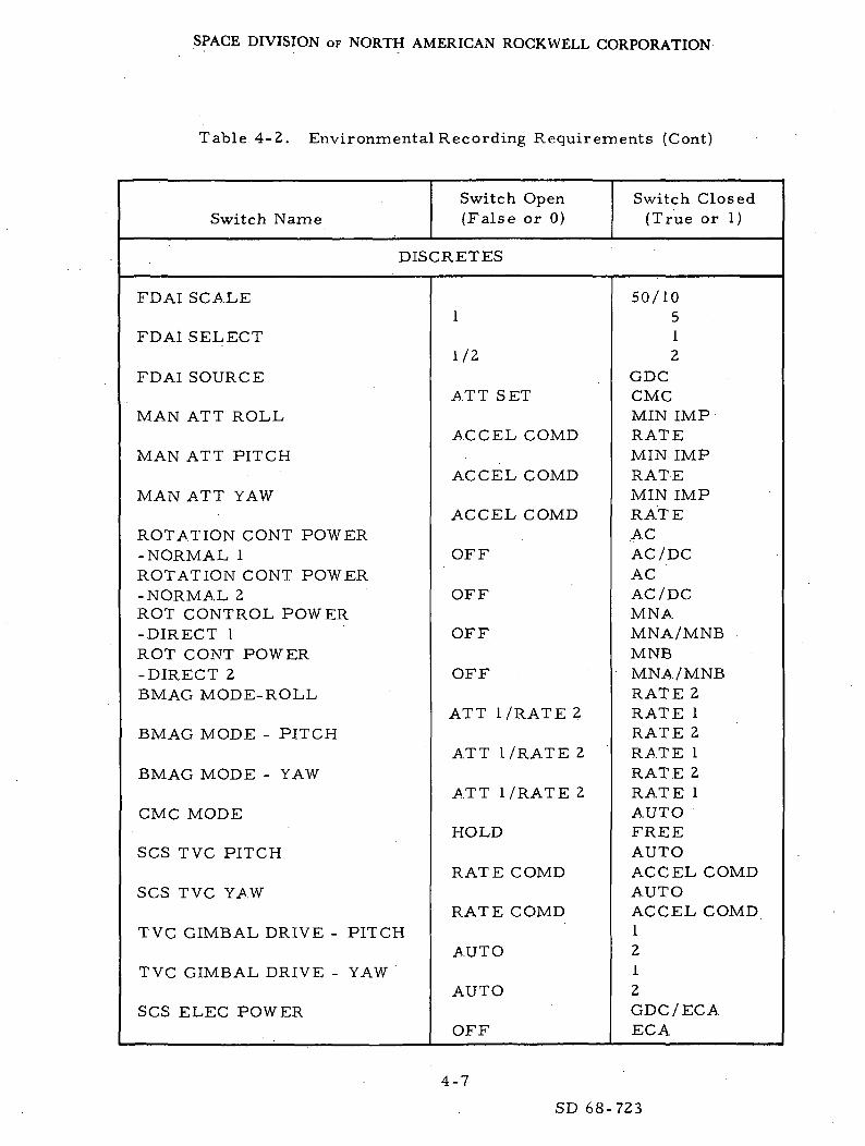
SPACE DIVISION OF NORTH AMERICAN ROCKWELL CORPORATION
Table 4-2. Environmental Recording Requirements (Cont)
Switch NameSwitch Open(False or 0)
Switch Closed(True or 1)
DISCRETES
FDAI SCALE
FDAI SELECT
FDAI SOURCE
MAN ATT ROLL
MAN ATT PITCH
MAN ATT YAW
ROTATION CONT POWER-NORMAL 1ROTATION CONT POWER-NORMAL 2ROT CONTROL POWER-DIRECT 1ROT CONT POWER-DIRECT 2BMAG MODE-ROLL
BMAG MODE - PITCH
BMAG MODE - YAW
CMC MODE
SCS TVC PITCH
SCS TVC YAW
TVC GIMBAL DRIVE - PITCH
TVC GIMBAL DRIVE - YAW
SCS ELEC POWER
1
1/2
ATT SET
ACCEL COMD
ACCEL COMD
ACCEL COMD
OFF
OFF
OFF
OFF
ATT I /RATE 2
ATT I /RATE 2
ATT I /RATE 2
HOLD
RATE COMD
RATE COMD
AUTO
AUTO
OFF
50/10512
GDCCMCMIN IMPRATEMIN IMPRATEMIN IMPRATEACAC /DCACAC /DCMNAMNA/MNB .MNBMNA/MNBRATE 2RATE 1RATE 2RATE 1RATE 2RATE 1AUTOFREEAUTOACCEL COMDAUTOACCEL COMD1212GDC /EC AEGA
4-7
SD 68-723

SPACE DIVISION OF NORTH AMERICAN ROCKWELL CORPORATION
Table 4-2. Environmental Recording Requirements (Gont)
Switch NameSwitch Open(False or 0)
Switch Closed(True or 1)
DISCRETES
SCS TVC SERVO PWR. 1
SCS TVC SERVO PWR 2
TELESCOPE TRUNNION
SPEED
AUTO RCS SELECT AI
C1
A2
c2
Bl
Dl
B2,
D2
A3
C3
A4
C4
B3
D3
B4
OFF
OFF
0°
MED
OFF
OFF
OFF
OFF
OFF
OFF
OFF
OFF
OFF
OFF
OFF
OFF
OFF
OFF
OFF
AC 1 /MNAAC 2 /MNAAC 1 /MNAAC2/MNBSLAVE TO SXT25°HILOMNAMNBMNAMNBMNAMNBMNAMNBMNAMNBMNAMNBMNAMNBMNAMNBMNAMNBMNAMNBMNAMNBMNAMNBMNAMNB-MNAMNBMNAMNB
4-8
SD 68-723

SPACE DIVISION OF NORTH AMERICAN ROCKWELL CORPORATION
Table 4-2. Environmental Recording Requirements (Cont)
Switch NameSwitch Open(False or 0)
Switch Closed(True or 1)
DISCRETES
AUTO RCS SELECT D4
LIMIT CYCLEATTITUDE DEADBANDRATETRANS CONT POWERS/C CONTROLSPS THRUST DIRECTDIRECT ULLAGETHRUST ONAV THRUST AAV THRUST BGDC ALIGNSPS GIMBAL MOTORS -
PITCH 1SPS GIMBAL MOTORS -
PITCH 2SPS GIMBAL MOTORS -
YAW 1SPS GIMBAL MOTORS -
YAW 2AV CGIMU CAGEENTRY EMS ROLLENTRY 0. 05GLV/SPS INDLV/SPS INDBMAG POWER 1BMAG POWER 2ATT SETFDAI POWER
OPTICS ZEROOPTICS COUPLINGOPTICS MODEUP TELEMETRY - MDCUP TELEMETRY - LEB
OFFOFFONMINLOWOFFSCSNORMALOFFOFFOFFOFFOFFOFF
OFF
OFF
OFF
LM/CSMOFFOFFONaGPIOFFOFFIMUOFF2
OFFDIRECTCMCBLOCKBLOCK
MNAMNBOFFMAXHIGHONCMCONONONNORMALNORMALONON
ON
ON
ON
CSMONONOFFPCS II/SIVBONONGDC12BOTHZERORESOLVEMAN.ACCEPTACCEPT
4-9
SD 68-723

SPACE DIVISION OF NORTH AMERICAN ROCKWELL CORPORATION
Table 4-2. Environmental Recording Requirements (Cont)
Switch NameSwitch Open(False or 0)
Switch Closed(True or 1)
DISCRETES
SM RCS PRI PROP
SM RCS SEC PROP
SM RCS H E 1
SM RCS HE 2
CM RCS PROP 1CM RCS PROP 2CM SM SEPRCS COMDRCS TRANSFER
ABCDABCDABCDABCD
OFFOFFOFFOFFOFFOFFOFFOFFOFFOFFOFFOFFOFFOFFOFFOFFOFFOFFOFFOFFSM
ONONONONONONONONONONONONONONONONONONONONCM
4-10
SD 68-723

SPACE DIVISION OF NORTH AMERICAN ROCKWELL CORPORATION
Table 4-3. Downlink Data Requirements
WordNumber First Register Second Register
POWERED LIST
1
2
3
4
5
6
7
8
9
10
11
12
13
14
15
16
17
18
19
20
21
22
23
I.D. (77774g)
CSM state vector (R )./s*
CSM state vector (R )
CSM state vector (R )f t
CSM state vector (V )
CSM state vector (V )
CSM state vector (V z)
CSM state vector time
Actual X CDU angle
Actual Z CDU angle
ADOTS roll orOGARATE
ADOTS pitch orOMEGA B pitch
ADOTS yaw orOMEGA B yaw
X attitude error
Z attitude error
THETADX
THETADZ
TIG
T.., Lambertr
RTARGX
RTARGY
RTARGZ
TGO
Synch bits (77340 )8
CSM state vector (R )
CSM state vector (R )
CSM state vector (R )L-t
CSM state vector (V ).X.
CSM state vector (V )
CSM state vector (V )
CSM state vector time
Actual Y CDU angle
ADOTS roll or OGARATE
ADOTS pitch or OMEGA B pitch
ADOTS yaw or OMEGA B
Y attitude error
RCS flags
THETADY
TIG
T LambertF
RTARGX
RTARGY
RTARGZ
TGO
yaw
4-11
SD 68-723

SPACE DIVISION OF NORTH AMERICAN ROCKWELL CORPORATION
Table 4-3. Downlink Data Requirements (Cont)
WordNumber First Register Second Register
POWERED LIST
24
25
26
27
28
29
30
31
32
33
34
35
36
37
38
39
40
41
42
43
44
45
46
47
48
PIPTIME1
DELVX
DELVY
DELVZ
PACTOFF
PCMD
CSTEER
REFSMMAT (RjC )
REFSMMAT (R C )1 ^
REFSMMAT (RjC^
REFSMMAT (R C )
REFSMMAT (R C )Lt C*
REFSMMAT (R C )£ J
Flagword 0
Flagword 2
Flagword 4
Flagword 6
Flagword 8
DSPTAB+0
DSPTAB+2
DSPTAB+4
DSPTAB+6
PIPTIME1
DELVX
DELVY
DELVZ
YACTOFF
YCMD
REFSMMAT (R^)
REFSMMAT (R C )1 Lt
REFSMMAT (R C )
REFSMMAT (R C )C* J.
REFSMMAT (R C )C* L*
REFSMMAT (R C )
Flagword 1
Flagword 3
Flagword 5
Flagword 7
Flagword 9
DSPTAB+1
DSPTAB+3
DSPTAB+5
DSPTAB+7
4-12
SD 68-723
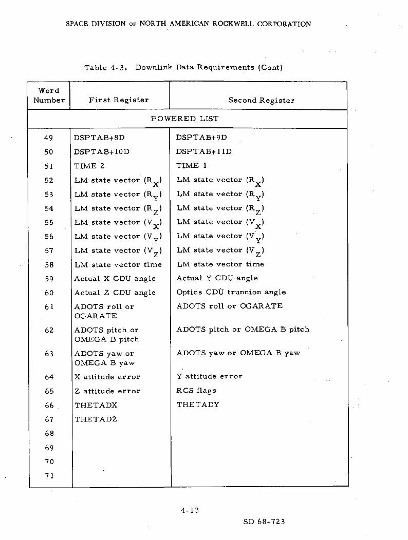
SPACE DIVISION OF NORTH AMERICAN ROCKWELL CORPORATION
Table 4-3. Downlink Data Requirements (Cont)
WordNumber First Register Second Register
POWERED LIST
49
50
51
52
53
54
55
56
57
58
59
60
61
62
63
64
65
66
67
68
69
70
71
DSPTAB+8D
DSPTAB+10D
TIME 2
LM state vector (R )-A.
LM state vector (Ry)
LM state vector (R7)£-t
LM state vector (V ).X,
LM state vector (V )
LM state vector (V )Z_i
LM state vector time
Actual X CDU angle
Actual Z CDU angle
ADOTS roll orOGARATE
ADOTS pitch orOMEGA B pitch
ADOTS yaw orOMEGA B yaw
X attitude error
Z attitude error
THETADX
THETADZ
DSPTAB+9D
DSPTAB+11D
TIME 1
LM state vector (R )
LM state vector (Rv)
LM state vector (R y)
LM state vector (V )
LM state vector (V )
LM state vector (V )
LM state vector time
Actual Y CDU angle
Optics CDU trunnion angle
ADOTS roll or OGARATE
ADOTS pitch or OMEGA B pitch
ADOTS yaw or OMEGA B yaw
Y attitude error
RCS flags
THETADY
4-13
SD 68-723
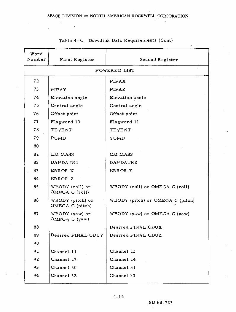
SPACE DIVISION OF NORTH AMERICAN ROCKWELL CORPORATION
Table 4-3. Downlink Data Requirements (Cont)
WordNumber First Register Second Register
POWERED LIST
72
73
74
75
76
77
78
79
80
81
82
83
84
85
86
87
88
89
90
91
92
93
94
PIP AY
Elevation angle
Central angle
Offset point
Flag word 10
TEVENT
PCMD
LM MASS
DAPDATR1
ERROR X
ERROR Z
WBODY (roll) orOMEGA C (roll)
WBODY (pitch) orOMEGA C (pitch)
WBODY (yaw) orOMEGA C (yaw)
Desired FINAL CDUY
Channel 1 1
Channel 13
Channel 30
Channel 32
PIP AX
PIPAZ
Elevation angle
Central angle
Offset point
Flagword 11
TEVENT
YCMD
CM MASS
DAPDATR2
ERROR Y
WBODY (roll) or OMEGA C (roll)
WBODY (pitch) or OMEGA C (pitch)
WBODY (yaw) or OMEGA C
Desired FINAL CDUX
Desired FINAL CDUZ
Channel 12
Channel 14
Channel 31
Channel 33
(yaw)
4-14
SD 68-723
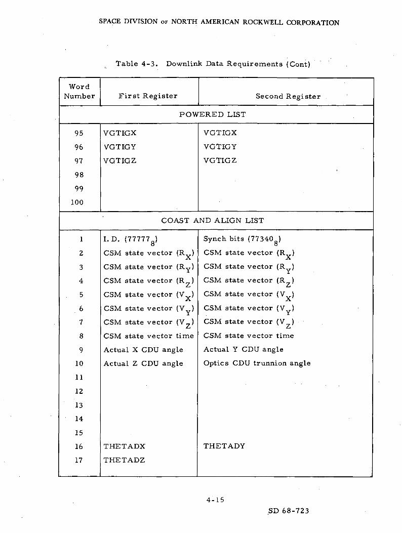
SPACE DIVISION OF NORTH AMERICAN ROCKWELL CORPORATION
Table 4-3. Downlink Data Requirements (Cont)
WordNumber First Register Second Register
POWERED LIST
95
96
97
98
99
100
VGTIGX
VGTIGY
VGTIGZ
VGTIGX
VGTIGY
VGTIGZ'
COAST AND ALIGN LIST
1
2
3
4
5
6
7
8
9
10
11
12
13
14
15
16
17
I. D. (77777 _)o
CSM state vector (R )
CSM state vector (Ry)
CSM state vector (RZ)
CSM state vector (Vx)
CSM state vector (V )
CSM state vector ( V _ )
CSM state vector time
Actual X CDU angle
Actual Z CDU angle
THETADX
THETADZ
Synch bits (77340Jo
CSM state vector (R )
CSM state vector (R )
CSM state vector (R )L-t
CSM state vector (V ).X.
CSM state vector (V )
CSM state vector (V )L-t
CSM state vector time
Actual Y CDU angle
Optics CDU trunnion angle
THETADY
4-15
SD 68-723

SPACE DIVISION OF NORTH AMERICAN ROCKWELL CORPORATION
Table 4-3. Downlink Data Requirements (Cont)
WordNumber First Register Second Register
COAST AND ALIGN LIST
18
19
20
21
22
23
24
25
26
27
28
29
30
31
32
33
34
35
36
37
38
39
40
41
42
STARID1
MARKTIMEl
Y CDU angle
Z CDU angle
X CDU angle
MARKTIME2
Y CDU angle
Z CDU angle
X CDU angle
REFSMMAT (R C )
REFSMMAT (R C )1 Lt
REFSMMAT (R C )
REFSMMAT (R 2C i )
REFSMMAT (R C )Ct £*
REFSMMAT (R C )w «J
Flagword 0
Flagword 2
Flag word 4
STARID2
MARKTIME 1
Optics shaft angle for last
Optics trunnion angle MARKTIMEl
MARKTIME 2
Optics shaft angle for last
Optics trunnion angle MARKTIME2
REFSMMAT (R C )
REFSMMAT (R C )J. Lt
REFSMMAT (R C )
REFSMMAT (R C )
REFSMMAT (R C )Lt C*
REFSMMAT (R C )^ 3
Flagword 1
Flagword 3
Flagword 5
4-16
SD 68-723
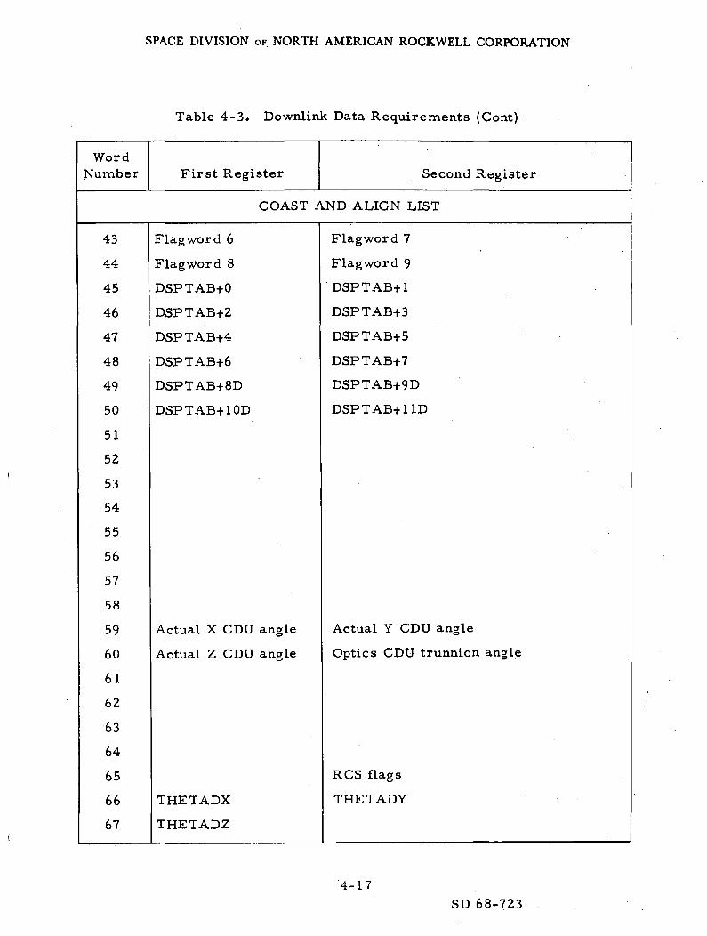
SPACE DIVISION OF NORTH AMERICAN ROCKWELL CORPORATION
Table 4-3. Downlink Data Requirements (Cont)
WordNumber First Register Second Register
COAST AND ALIGN LIST
43
44
45
46
47
48
49
50
51
52
53
54
55
56
57
58
59
60
61
62
63
64
65
66
67
Flag word 6
Flagword 8
DSPTAB+0
DSPTAB+2
DSPTAB+4
DSPTAB+6
DSPTAB+8D
DSPTAB+10D
Actual X CDU angle
Actual Z CDU angle
THETADX
THETADZ
Flagword 7
Flagword 9
DSPTAB+1
DSPTAB+3
DSPTAB+5
DSPTAB+7
DSPTAB+9D
DSPTAB+1 ID
Actual Y CDU angle
Optics CDU trunnion angle
RCS flags
THETADY
4-17
SD 68-723
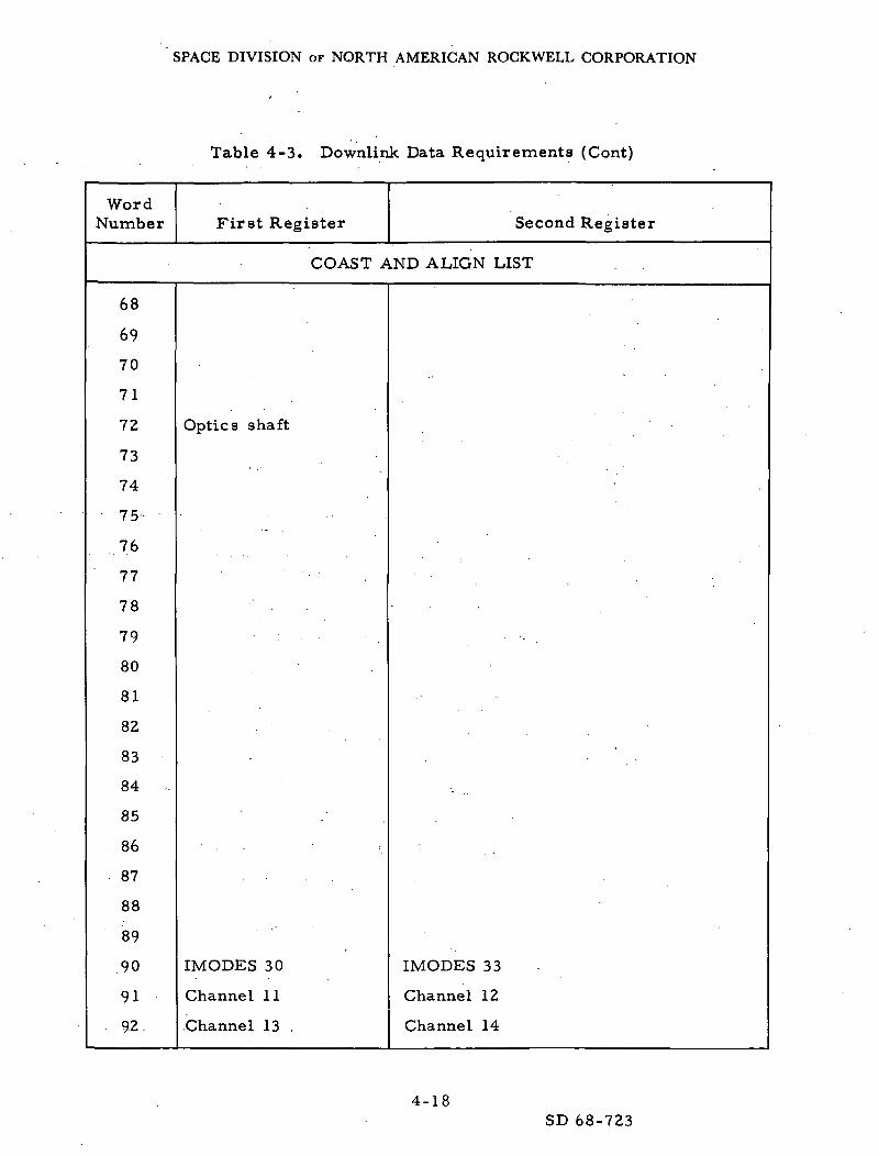
SPACE DIVISION OF NORTH AMERICAN ROCKWELL CORPORATION
Table 4-3. Downlink Data Requirements (Cont)
WordNumber
68
69
70
71
72
73
74
75
77
78
79
80
81
82
83
84 -
85
86
87
88
89
90
91
. 92
First Register Second Register
COAST AND ALIGN LIST
Optics shaft
•- •
IMODES 30
Channel 11
Channel 13
•_
IMODES 33
Channel 12
Channel 14
4-18SD 68-723

SPACE DIVISION OF NORTH AMERICAN ROCKWELL CORPORATION
t Table 4-3. Downlink Data Requirements (Cont)
WordNumber First Register Second Register
COAST AND ALIGN LIST
93
94
95
96
97
98
99
100
Channel 30
Channel 32
DSPTAB+0
DSPTAB+2
DSPTAB+4
DSPTAB+6
DSPTAB+8D
DSPTAB+10D
Channel 31
Channel 33
DSPTAB+1
DSPTAB+3
DSPTAB+5
DSPTAB+7
DSPTAB+9D
DSPTAB+1 ID
RENDEZVOUS AND PRETHRUST LIST
1
2
3
4
5
6
7
8
9
10
11
12
13
I.D. (77775g)
CSM state vector (R )A
CSM state vector (R )
CSM state vector (R )£-»
CSM state vector (Vx)
CSM state vector (V )
CSM state vector (V )
CSM state vector time
Actual X CDU angle
Actual Z CDU angle
ADOTS roll orQGARATE
ADOTS pitch orOMEGA B pitch
ADOTS yaw orOMEGA B yaw
Synch bits (77340 )o
CSM state vector (R )
CSM state vector (R )
CSM state vector (R )L-t
CSM state vector (V )X
CSM state vector (V )
CSM state vector (V )
CSM state vector, time
Actual Y CDU angle
Optics CDU trunnion angle
ADOTS roll or OGARATE
ADOTS pitch or OMEGA B pitch
ADOTS yaw or OMEGA B yaw
4-19SD 68-723

SPACE DIVISION OF NORTH AMERICAN ROCKWELL CORPORATION
Table 4-3. Downlink Data Requirements (Cont)
WordNumber First Register Second Register
RENDEZVOUS AND PRETHRUST LIST
14
15
16
17
18
19
20
21
22
23
24
25
26
27
28
29
30
31
32
33
34
35
36
37
38
X attitude error
Z attitude error
THETADX
THETADZ
TIG
T LambertF
RTARGX
RTARGY
RTARGZ
MARK TIME
Y CDU angle
Z CDU angle
X CDU angle
TPI TIME
ECSTEER
DELVTPF (magnitude)
TPF time
DELVSLV X
DELVSLV Y
DELVSLV Z
Range
Y attitude error
RCS flags
THETADY
TIG
T LambertF
RTARGX •'
RTARGY
RTARGZ
MARK TIME
Optics shaft angle
Optics trunnion angle
OPTIC MARKS
TPI TIME .
DELVTPF (magnitude)
TPF time .
DELVSLV X
DELVSLV Y
DELVSLV Z
Range
4-20
SD 68-723

SPACE DIVISION OF NORTH AMERICAN ROCKWELL CORPORATION
Table 4-3. Downlink Data Requirements (Cont)
WordNumber First Register Second Register
RENDEZVOUS AND PRETHRUST LIST
39
40
41
42
43
44
45
46
47
48
49
50
51
52
53
54
55
56
57
58
59
60
62
Range rate
Flagword 0
Flagword 2
Flagword 4
Flagword 6
Flagword 8
DSPTAB+0
DSPTAB+2
DSPTAB+4
DSPTAB+6
DSPTAB+8D
DSPTAB+10D
TIME 2
LM state vector (R,,)
LM state vector (Rv)
LM state vector (R )
LM state vector (V )
LM state vector (V )
LM state vector (V )
LM state vector time
Actual X CDU angle
Actual Z CDU angle
ADOTS roll orOGARATE
ADOTS pitch orOMEGA B pitch
Range rate
Flagword 1
Flagword 3
Flagword 5
Flagword 7
Flagword 9
DSPTAB+1
DSPTAB+3
DSPTAB+5
DSPTAB+7
DSPTAB+9D •:• y
DSPTAB+1 ID
TIME 1
LM state vector (Rv)2\.
LM state vector (RY)
LM state vector (R )
LM state vector (V )A
LM state vector (V )
LM state vector (V )£~*
LM state vector time
Actual Y CDU angle
Optics CDU trunnion angle
ADOTS roll or OGARATE
ADOTS pitch or OMEGA B pitch
4-21
SD 68-723

SPACE DIVISION OF NORTH AMERICAN ROCKWELL CORPORATION
Table 4-3. Downlink Data Requirements (Corit)
WordNumber First Register Second Register
RENDEZVOUS AND PRETHRUST LIST .
63
64
65
66
67
68
69
70
71
72
73
74
75
76
77
78
79
80
81
82
83
84
85
ADOTS yaw orOMEGA B yaw
X attitude error
Z attitude error
THETADX
THETADZ
Optics shaft
Elevation angle
Central angle
Offset point
DELVEET3 X
DELVEET3 Y
DELVEET3 Z
LM MASS
DAPDATR1
ERROR X
ERROR Z
WBODY (roll) orOMEGA C (roll)
ADOTS yaw or OMEGA B
Y attitude error
RCS flags r
THETADY
Elevation angle
Central angle
Offset point
DELVEET3 X
DEL.VEET3 Y
DELVEET3 Z
CM MASS
DAPDATR2
ERROR Y
WBODY (roll) or OMEGA
yaw
C (roll)
4-22
SD 68-723

SPACE DIVISION OF NORTH AMERICAN ROCKWELL CORPORATION
Table 4-3. Downlink Data Requirements (Cont)
WordNumber First Register Second Register
RENDEZVOUS AND PRETHRUST LIST
86
87
88
89
90
91
92
93
94
95
96
97
98
99
100
WBODY (pitch) orOMEGA C (pitch)
WBODY (yaw) orOMEGA C (yaw)
Desired FINALCDU Y
Channel 11
Channel 13
Channel 30
Channel 32
RTHETA
GEODETIC LAT
LONG
V PRED
GAMMA(EI)
WBODY (pitch) or OMEGA C (pitch)
WBODY (yaw) or OMEGA C (yaw)
Desired FINAL CDU X
Desired FINAL CDU Z
Channel 12
Channel 14
Channel 31
Channel 33
RTHETA
GEODETIC LAT
LONG
V PRED
GAMMA(EI)
ENTRY AND UPDATE LIST
1
2
3
4
5
6
I.D. (77776Jo
CSM state vector (R )
CSM state vector (R )
CSM state vector (R )
CSM state vector (Vv).A.
CSM state vector (V )
Synch bits (77340Jo
CSM state vector (R „)XX
CSM state vector (R )
CSM state vector (R )
CSM state vector (V )
CSM state vector (V )
4-23
SD 68-723
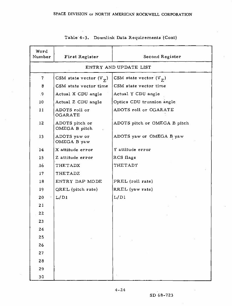
SPACE DIVISION OF NORTH AMERICAN ROCKWELL CORPORATION
Table 4-3. Downlink Data Requirements (Cont)
WordNumber First Register Second Register
ENTRY AND UPDATE LIST
7
8
9
10
11
12
13
14
15
16
17
18
19
20
21
22
23
24
25
26
27
28
29
30
CSM state vector (V )^j
CSM state vector time
Actual X CDU angle
Actual Z CDU angle
ADOTS roll orOGARATE
ADOTS pitch orOMEGA B pitch
ADOTS yaw orOMEGA B yaw
X attitude error
Z attitude error
THETADX
THETADZ
ENTRY DAP MODE
QREL (pitch rate)
L/D1
CSM state vector (V„)£-t
CSM state vector time
Actual Y CDU angle
Optics CDU trunnion angle
ADOTS roll or OGARATE
ADOTS pitch or OMEGA B pitch
ADOTS yaw or OMEGA B yaw
Y attitude error
RCS flags
THETADY
PREL (roll rate)
RREL (yaw rate)
L/D1
4-24SD 68-723

SPACE DIVISION OF NORTH AMERICAN ROCKWELL CORPORATION
Table 4-3. Downlink Data Requirements (Cont)
WordNumber First Register Second Register
ENTRY AND UPDATE LIST
31
32
33
34
35
36
37
38
39
40
41
42
43
44
45
46
47
48
49
50
51
52
53
54
Roll error
LATANG
ROOT
THETAH
GEODETIC LAT(SPLSH)
LONG (SPLSH)
ALPHA
Flagword 0
Flagword 2
Flagword 4
Flagword 6
Flagword 8
DSPTAB+0
DSPTAB+2
DSPTAB+4
DSPTAB+6
DSPTAB+8D
DSPTAB+10D
TIME 2
PIPTIME1
DELVX
DELVY
Roll angle
LATANG
ROOT
THETAH
GEODETIC LAT (SPLSH)
LONG (SPLSH)
BETA
Flagword 1
Flagword 3
Flagword 5
Flagword 7
Flagword 9
DSPTAB+1
DSPTAB+3
DSPTAB+5
DSPTAB+7
DSPTAB+9D
DSPTAB+1 ID
TIME 1
PIPTIME1
DELVX
DELVY
4-25
SD 68-723

SPACE DIVISION OF NORTH AMERICAN ROCKWELL CORPORATION
Table 4-3. Downlink Data Requirements (Cont)
WordNumber First Register Second Register
ENTRY AND UPDATE LIST
55
56
57
58
59
60
61
62
63
64
65
66
67
68
69
70
71
72
73
74
75
76
77
DELVZ
TTE (EMS)
VIO
VPRED (El)
Actual X CDU angle
Actual Z CDU angle
ADOTS roll orOGARATE
ADOTS pitch orOMEGA B pitch
ADOTS yaw orOMEGA B yaw
X attitude error
Z attitude error
ERROR X
ERROR Z
THETADY
ENTRY DAP MODE
OREL (pitch rate)
DELVZ
TTE (EMS)
VIO
VPRED (El)
Actual Y CDU angle
Optics GDU trunnion angle
ADOTS roll or OGARATE
ADOTS pitch or OMEGA B pitch
ADOTS yaw or OMEGA B yaw
Y attitude error
RCS flags
ERROR Y
THETADX
THETADZ
PREL (roll rate)
RREL (yaw rate)
4-26
SD 68-723
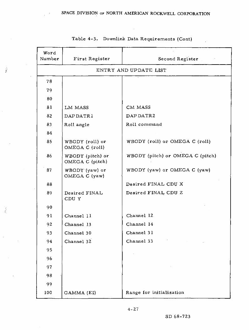
SPACE DIVISION OF NORTH AMERICAN ROCKWELL CORPORATION
Table 4-3. Downlink Data Requirements (Cont)
WordNumber First Register Second Register
ENTRY AND UPDATE LIST
78
79
80
81
82
83
84
85
86
87
88
89
90
91
92
93
94
95
96
97
98
99
100
LM MASS
DAPDATR1
Roll angle
WBODY (roll) orOMEGA C (roll)
WBODY (pitch) orOMEGA C (pitch)
WBODY (yaw) orOMEGA C (yaw)
Desired FINALCDU Y
Channel 11
Channel 13
Channel 30
Channel 32
GAMMA (El)
CM MASS
DAPDATR2
Roll command
WBODY (roll) or OMEGA C (roll)
WBODY (pitch) or OMEGA C (pitch)
WBODY (yaw) or OMEGA C
Desired FINAL CDU X
Desired FINAL CDU Z
Channel 12
Channel 14
Channel 3 1
Channel 33
Range for initialization
(yaw)
4-27
SD 68-723
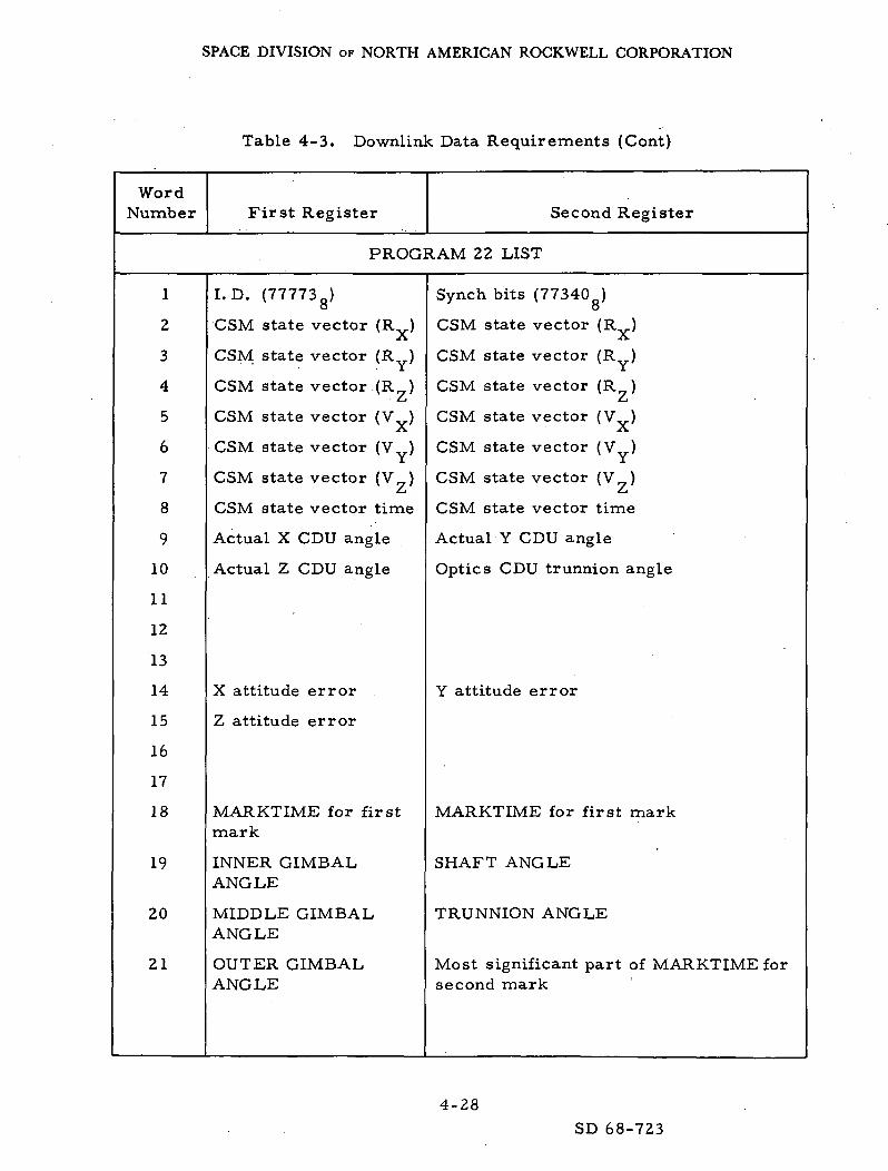
SPACE DIVISION OF NORTH AMERICAN ROCKWELL CORPORATION
Table 4-3. Downlink Data Requirements (Cont)
WordNumber First Register Second Register
PROGRAM 22 LIST
1
2
3
4
5
6
7
8
9
10
11
12
13
14
15
16
17
18
19
20
21
I.D. (77773g)
CSM state vector (R )-X.
CSM state vector (R )
CSM state vector (R)• £-1
CSM state vector (V ).A.
CSM state vector (V )
CSM state vector (V )Zj
CSM state vector time
Actual X CDU angle
Actual Z CDU angle
X attitude error
Z attitude error
MARKTIME for firstmark
INNER GIMBALANGLE
MIDDLE GIMBALANGLE
OUTER GIMBALANGLE
Synch bits (77340 )o
CSM state vector (R )Jv
CSM state vector (R )
CSM state vector (R )i
CSM state vector (V ).X,
CSM state vector (V )
CSM state vector (V )£-i
CSM state vector time
Actual Y CDU angle
Optics CDU trunnion angle
Y attitude error
MARKTIME for first mark
SHAFT ANGLE
TRUNNION ANGLE
Most significant part of MARKTIME forsecond mark
4-28
SD 68-723
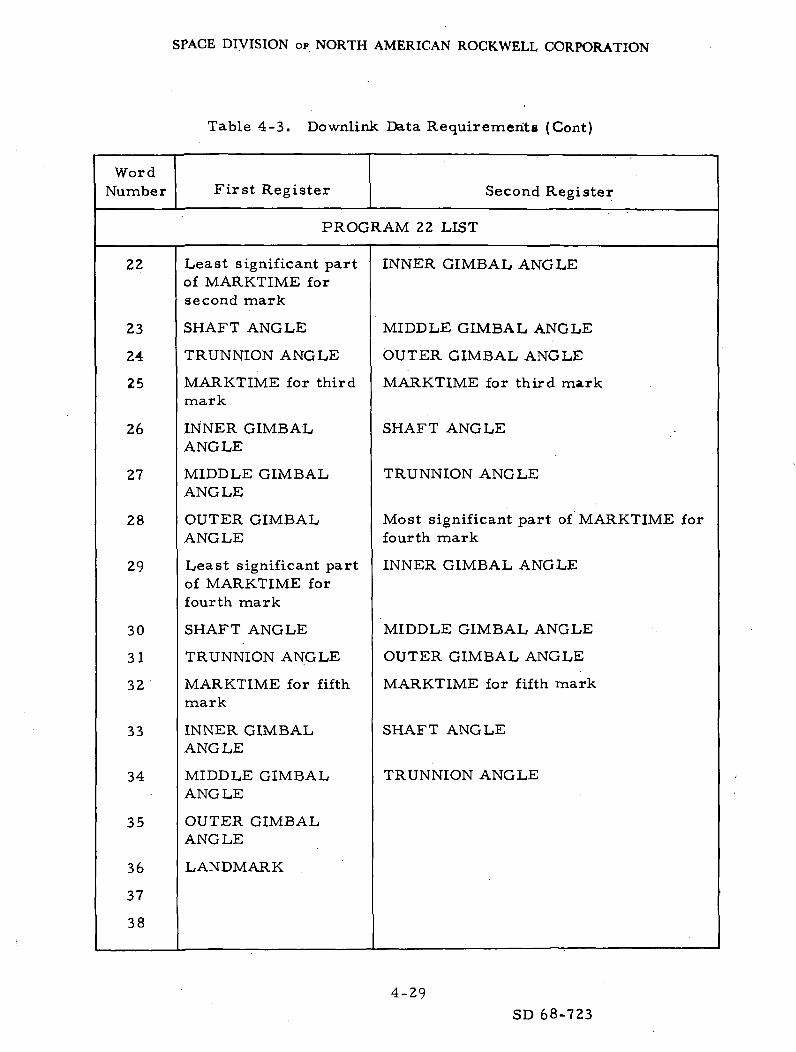
SPACE DIVISION OF NORTH AMERICAN ROCKWELL CORPORATION
Table 4-3. Downlink Data Requirements (Cont)
WordNumber First Register Second Register
PROGRAM 22 LIST
22
23
24
25
26
27
28
29
30
31
32
33
34
35
36
37
38
Least significant partof MARKTIME forsecond mark
SHAFT ANGLE
TRUNNION ANGLE
MARKTIME for thirdmark
INNER GIMBALANGLE
MIDDLE GIMBALANGLE
OUTER GIMBALANGLE
Least significant partof MARKTIME forfourth mark
SHAFT ANGLE
TRUNNION ANGLE
MARKTIME for fifthmark
INNER GIMBALANGLE
MIDDLE GIMBALANGLE
OUTER GIMBALANGLE
LANDMARK
INNER GIMBAL ANGLE
MIDDLE GIMBAL ANGLE
OUTER GIMBAL ANGLE
MARKTIME for third mark
SHAFT ANGLE
TRUNNION ANGLE
Most significant part of MARKTIME forfourth mark
INNER GIMBAL ANGLE
MIDDLE GIMBAL ANGLE
OUTER GIMBAL ANGLE
MARKTIME for fifth mark
SHAFT ANGLE
TRUNNION ANGLE
4-29
SD 68-723

SPACE DIVISION OF NORTH AMERICAN ROCKWELL CORPORATION
Table 4-3. Downlink Data Requirements (Cont)
WordNumber First Register Second Register
PROGRAM 22 LIST
39
40
41
42
43
44
45
46
47
48
49
50
51
52
53
54
55
56
57
58
59
60
61
Flag word 0
Flagword 2
Flag word 4
Flagword 6
Flagword 8
DSPTAB+0
DSPTAB+2
DSPTAB+4
DSPTAB+6
DSPTAB+8D
DSPTAB+10D
TIME 2
LANDMARKLATITUDE
LANDMARKLONGITUDE
LANDMARKALTITUDE
Actual X CDU angle
Actual Z CDU angle
-
Flagword 1
Flagword 3
Flagword 5
Flagword 7
Flagword 9
DSPTAB+1
DSPTAB+3
DSPTAB+5
DSPTAB+7
DSPTAB+9D
DSPTAB+1 ID
TIME 1
LANDMARK LATITUDE
LANDMARK LONGITUDE
LANDMARK ALTITUDE
Actual Y CDU angle
Optics CDU trunnion angle
4-30
SD 68-723

SPACE DIVISION OF NORTH AMERICAN ROCKWELL CORPORATION
Table 4-3. Downlink Data Requirements (Cont)
WordNumber First Register Second Register
PROGRAM 22 LIST
62
63
64
65
66
67
68
69
70
71
72
73
74
75
76
77
78
79
80
81
82
83
84
Optics shaft
No. of marks
Landing site vectorX comp.
Landing site vectorY comp.
Landing site vectorZ comp.
Landing site vector X comp.
Landing site vector Y comp.
Landing site vector Z comp.
4-31SD 68-723

SPACE DIVISION OF NORTH AMERICAN ROCKWELL CORPORATION
Table 4-3. Downlink Data Requirements (Cont)
WordNumber First Register Second Register
PROGRAM 22 LIST
85
86
87
88
89
90
91
92
93
94
95
96
97
98
99
100
Channel 11
Channel 12
ChannelSO
Channel 32
Channel 12
Channel 14
Channel 31
Channel 33
4-32
SD 68-723

SPACE DIVISION OF NORTH AMERICAN ROCKWELL CORPORATION
APPENDIX
REFERENCES
1. Mission Evaluation 101 - Study Analysis Report. SD 68-452(24 September 1968)
2. Mission Requirement - 'D' Type Mission - LM Evaluation and CombinedOperations. NASA MSC SPD 8-R-005 (8 April 1968, revised 1 July 1968)
3. Apollo Mission D (AS-503/CSM-103/LM-3) - Spacecraft Reference Tra-jectory Volume 1 - Nominal Trajectory. MSC Internal Note No. 68-FM-93(30 April 1968)
4. Apollo Operations Handbook - Command and Service Modules -Volume 2 - Operational Procedure^!SD 67-778, SM2A-03-SC103-(2)(1 August 1968)
5. CSM Rendezvous Procedures - D Mission Preliminary Copy. NASAMSC, (19 July 1968).
A-l
SD 68-723