Embed Size (px)
Citation preview

ms. mmsuamam as THE m HAAS-VAN
mm mm: BY ms sow mamas; 133
295
THS
”(has-2's :39? {he Segraa of M. S.
‘ «2 “LM' a? «glistzu ',5 g‘: raft ‘
EI-‘aiufizzsélw‘¢ 3mm; Efih‘ii’vERSmY

TTTTTT ' Innlmnmmlimmmnmmrurmmml":_ 3 1293 01743 0012 '
LIBRARY
Michigan State
University

ABSTRACT
THE MEASUREMENT OF THE
DE HAAS—VAN ALPHEN EFFECT
BY THE GOUY METHOD
by Richard Norman wagner
A torsionptype, magnetic susceptibility, beam.balance capable of
making differential weighings of 30 micrograms on samples weighing up
to 50 grams was built. Force measurements were made on a single crys-
tal of bismuth with magnetic fields up to 17,700 gauss at a temperature
of h.2°K using the Gouy method. The results of these measurements
illustrate the utility of the Gouy method in detecting De Haas-Van Alphen
oscillations.

THE MEASUREMENT OF THE
DE HAAS—VAN ALPHEN EFFECT
BY THE GOUY METHOD
BY
Richard Norman wagner
A THESIS
Submitted to
Michigan State University
In partial fulfillment of the requirements
for the degree of
MASTER OF SCIENCE
Department of Physics and Astronomy
l96h

.\
V;C)
will
a“
L}‘
.N
4;““k
(2:
ACKNOWLEDGMENTS
The author wishes to thank Dr. Meyer Garber for his guidance in
the design of the apparatus and his suggestion to use the Gouy method
to measure De Haas-Van Alphen oscillations. This work was made possi-
ble through the financial support of the National Science Foundation
and the Office of Ordnance Research.
ii

TABLE OF CONTENTS
CHAPTER PAGE
I INTRODUCTION . . . . . . o . o o o o o . o . . o . o o . o 0
II THEORX . . . o . . . . . . . . o o . . o o o o o o o o o o 0
III APPARATUS . . . . . . . . . o . o . . . o o . o o . o o o o
MagnetandMagneticShield...............o
c»
-a
-4
\u
+4
Vacuum.Enclosure . . . . . . . . . . . . . . . . . . . . .
BalanceandOpticalSystem................ 13
Electronics . . . . . . . . . . . . . . . . . o . . o . o 20
IV DESCRIPTION OF EXPERIMENTS . . . . . . . . . . . . . . . . . 26
Absolute Susceptibility . . . . . . . . . . . . . . . . . 28
Rotational Experiment . . . . . . . . o . o . . . . . . o 32
De Haas-van Alphen Effect . . . . . . . . . . . . . . . o 37
vDISCUSSION......................... 1:3
VIBIBLIOGRAPHY........................ uh
VIIAPPENDIXOOOOOQQOO00000000000000... ’45
iii

TABLE
II
III
VI
VII
VIII
XI
XII
LIST OF TABLES
Electrical Components 0 o o o o o o o o o o o o o o o o o
Magnet Calibration with Three Inch Gap Using Rawson Type
820 Fluxmeter o o o o o o o o o o o o o o o o o o o o o
Calculations of the Absolute Susceptibility at Room _
Temperature..........ooooaooooooo
Orientation of the Trigonal Axis Calculated from the
Rotational Data 0 o o o o o o o o o o o o o o o o o o 0
Comparison of Susceptibility Peaks and Magnetothermal
Peaks 0 o o o o o o o o o o o o o o o o o o o o o o o 0
Absolute Susceptibility Data, Taken at Room Temperature
(22°C) with the Sample in a Vacuum . . . . . . o o . .
Absolute Susceptibility Date, Taken at Room Temperature
(22°C) with the Sample in One Atmosphere of Oxygen . o
Rotational Data, at Room Temperature (22°C) and at a
Field of h,2OO Gauss, Taken August 28, 1963 . . . . . .
Rotational Data, at Room Temperature (23%) and at a
Field of h,200 Gauss, Taken August 29, 1963 . . . . .
Rotational.Data, at Room.Temperature (22°C) and at a
Field of 11,270 Gauss, Taken August 28, 1963 . . . . .
Rotational Data, at Room Temperature (23°C) and at a
Field of 11,270 Gauss, Taken August 29, 1963 . . . . .
De Haas-Van Alphen Effect.Data Taken at h.2°K . . . . . .
iv
PAGE
23
27
31
36
h2
h6
h7
h8
h9
SO
51
52

..
rr
Oa
va
I
ar
n
O‘
r
aa
o
an
a
va
I
OQ
’
cO
1
.a
-
oa.
a
rt
9
o.
I
a.
v
Ic
i
nn
a
aI
t
a-
a
.c
a.

LIST OF FIGURES
FIGURE PAGE
1 Magnet Shield . .’. . . . . . . . . . . . . . . . . o . o o 9
2 Effect of Magnet Shield . . . . . . . . . . . . . . . . . . 10
3 Vacuum Can . . . . . . . . . . . . . . . . . . . o . . . . . 11
h Balance . . . . . . o o . o . o . . . . . . o . . . . . . . 15
S OpticalSystem....................... 17
6 Sample Holder . . . e o o . o . o o o o o . . o . . o . o . 18
7 Improved Beam End Coupling . . . . . . . . . . . . o . . . . l9
8 Servosystem . . . . . . . . . . o o . . . . . . . . . . . . 21
9 Circuit 0 o o o o o . o o o o o o o o o o o o o o o o o o o 22
10 Effect of Surrounding the Sample with One Atmosphere of
Oxygen on the Restoring Voltage, Room Temperature . . . . 30
11 Dependence of Restoring Voltage on Magnet Position, Room
Temperature, h,200 Gauss . . . . . . . . o o . o . . . . o 33
12 Dependence of Restoring Voltage on Nhgnet Position, Room
Temperature, 11,270 Gauss . . . . ... . . . . . . . . o o 3h
13 Crystal Orientation Coordinates . . . . . o . . o o o o . o 35
1h Dependence of Restoring Voltage on the Magnetic Field, h.2°K 39
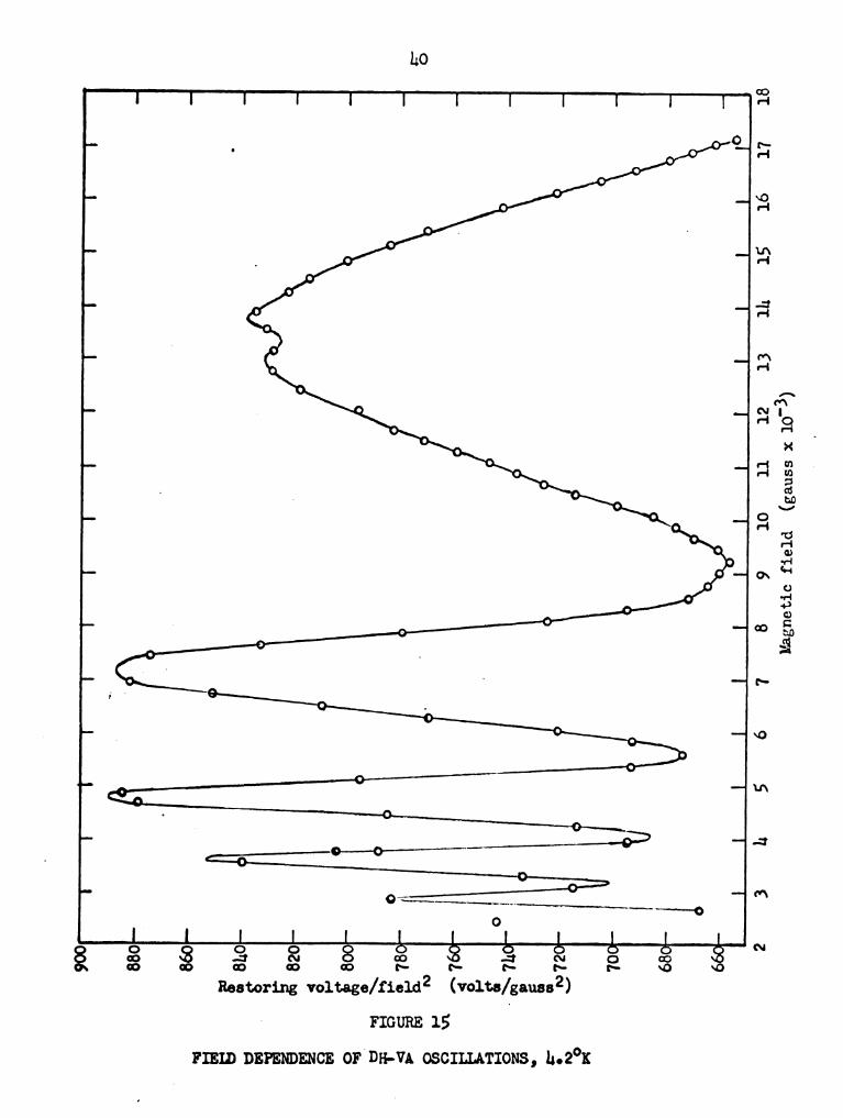
15 Field Dependence of DHEVA Oscillations, h.2°K . . . . . . . hO
l6 Dependence of DHeVA Oscillations on the Reciprocal of the
Fiéld,h020Kooooooooooo000000000000 ’41

LIST OF ILLUSTRATIONS
ILLUSTRATION PAGE
I Balance 0 o o o o o o o o o o o o o o o o o o o o o o o o 0 1h
II Balance and Optical System 0 o o o o o o o o o o o o o o o o 16
vi
I INTRODUCTION
A torsion beam balance was constructed to measure the magnetic
susceptibility of metals at low temperatures. The balance follows the
1’2 Samples weighing up to 50general design of previous balances.
grams weight can be used. The uncertainty in a given weighing is about
30 micrograms at present. Restoring force is supplied by a current
carrying coil interacting with a permanent magnet. An optical-elec-
trical servosystem is used to keep the beam in null position, minimiz-
ing eddy current effects and increasing the effective stiffness.
The balance is sensitive enough to use the Faraday method, but to
avoid the necessity of obtaining properly shaped pole faces as are used
to reduce sample positioning errors, the Gouy method was used. Further,
it was decided to investigate the suggestion, to the author, by
Dr. J. F. Cochran and Dr. M. Garber that De Haas-Van Alphen (here after
referred to as DHeVA) oscillations might be studied using the Gouy
method.
Previous studies of DH-VA oscillations have been carried out with
the sample suspended in a nearly uniform field. Shoenberg used the Far-
aday method in his inital studies of the DH—VA effect in bismuth.3
This method measures some average value of the susceptibility when the
1M0 Garber, We Go H811”, and H. G. HOeve, Can. J. Phys. 2.9-) 1595,
(1956).
2F. T. Hedgcock, Rev. Sci. Instr. 2A: 390, (1960).
3D. Shoenberg and M. Zakie Uddin, Proc. Roy. Soc. igé, 701, (1935).
1

susceptibility is field dependent, thereby making the Faraday meth-
od useless in resolving closely spaced DH+VA oscillations. For the
above reason Shoenberg used the torsion.method in a later experiment
on bismuth.)4 The torsion.method is simple and sensitive, but it has
the disadvantage that it measures the difference in the susceptibili-
ties along the principal axes. Present day DHAVA studies are fre-
quently made with pulsed very high fields using a pick-up method for
measuring the susceptibility.
The balance was constructed for use in investigating the suscepti-
bility of alloys but it was decided to try and use it to detect‘DHeVA
oscillations in bismuth. The absolute susceptibility of bismuth was
not accurately determined because the orientation of the bismuth crys-
tal was not well determined. The measurements, however, show that
DHEVA oscillations can be detected easilye
hD. Shoenberg, Proc. Roy. Soc. 119, 3h1, (1939).

II THEORY
The magnetic force on a long rod of material suspended in a.mag—
netic field gradient can be calculated by considering the virtual work
required to make a virtual displacement, 62, of the rod. This virtual
work corresponds to the change in the magnetic free energy of the rod
when the displacement is an isothermal reversible process. Calcula-
tion of the virtual work can be simplified if the following assumptions,
readily realizable with the Gouy method, are made:
1) The rod material is homogeneous.
2) The cross sectional area, A, of the rod in the plane perpendicun
lar to the displacement, Oz, is a constant.
3) The ends of the rod are in regions of uniform field.
Now, the virtual work required to displace the entire rod a dis-
tancetéz can be considered as the work done in taking a small volume,
AOz, from one end of the rod to the other.
hath no essential loss of generality it will be further assumed
that the permeability of the rod material is isotropic, i.e., a scalar.
The medium surrounding the rod is a vacuum, and one end of the rod is
in a region of zero field.
The difference in the magnetic free energy of the rod is equal to
the magnetic free energy of the small volume of material, A62, in the
high field region. This energy is the difference between the energy of
the field, due to fixed current sources, without the presence of the
small piece of magnetic material, and, if the magnetic material is pres-
ent, the amount of work done by the current sources necessary to re-
3


I;
store the currents from zero to their initial value.5 The additional
work necessary to build up the currents in the presence of the body is
B
U-= £3 [HIE-HBFHBi-ZSHdBJdV
V 0
where V is the volume of the magnetic material, H and B are the fields
in the presence of the magnetic material, and H1 and B1 are the fields
in the absence of the magnetic material. By substituting
BI=JJ.(HI+MI)=}J.HI 3 B=p.(H+M)= AWN-X)
into the above equation we have (/1, -:..- permeability of free Space)
* H
U= $11.8 [X(H,—H)H+2$HdM-Jdv '
v o
If the high field region is at the bottom of the sample and the
mechanical force, 3‘, on the sample and the displacement, 82, are
taken in the upward direction
H
352 =12A62N.[‘X.(H,—H)H +28 HdM]
o
H
3- =él-A1J.[’X.(HI-H)H+23HOM] -
, o
5J. A. Stratton, Electricity and Magnetism (McGraw—Hill, New York,
1911-1), p. 128 o

The force is proportional to the free energy density at the high
field end of the rod and to the cross sectional area of the rod. There-
fore fluctuations in the force on the rod correspond directly to fluc-
tuations of the free energy density at the high field end of the rod.
It is often assumed that the presence of the magnetic material
does not affect the current sources, in which case H1 = H, and the usu-
al expression for the force on the rod is written
H
3=ApongM .
C)
For materials in which M/H -'-' 'X. Z constant
3‘ = 'Ep.A'X.H2.
In cases where the magnetic susceptibility varies with the applied
magnetic field the theoretical analysis is usually based on the free
energy expression. This corresponds directly to the measured force on
the sample. This simple and direct feature of the Gouy method seems
hitherto to have been overlooked.
In the case of the De Haas-Van Alphen effect the expression for
the free energy may be written6
§ _2m_<_Tm‘c
F‘><TH2 e ““4 COST—5%“
where constant terms and the quadratic background rise of F with H are
6R. Go Chambers, Can. J. Phys. 21-, 1395 (1956).

omitted. This expression is characterized by a periodic variation in
1/H with the period given by
Mat-ea<:A.
where A.o refers to the extremal cross sectional area in.momentum
space of the Fermi surface, taken perpendicular to the magnetic field.
Thus, the measurement of the period of the oscillations gives topolog-
ical information about the Fermi surface of metals. The amplitude vari-
ation which gives information about the effective masses, is rather more
complicated. It has not been analyzed in this work. The main object
is to show the utility of the Gouy method for De Haas-Van Alphen ef-
fect measurements. The data obtained using the Gouy method will be
compared with data obtained using the magnetothermal method.

III APPARATUS
A Gouy-type apparatus was built utilizing a torsion beam balance.
An optical—electrical system is used to detect the position of the beam
and an electro-mechanical system is used to restore the beam to null
position.
The beam and sample are surrounded by a vacuum enclosure includ-
ing a long Pyrex tube, called a cold finger, in which the sample is
suspended. The cold finger is surrounded by a partially silvered
dewar with provision for pumping on liquid helium.
A commerical electromagnet which can be rotated about a vertical
axis was used. In an attempt to reduce the magnetic field at the low
field and of the sample, a cylindrical iron shield was placed around
the top end of the sample.
Magnet and Magnetic Shield
The magnet was a Harvey-wells model LplSB. It was used with 12"
dia. x 2.375" cylindrical pole faces which were machined from Armco Mag-
netic Ingot Iron.1 With a gap width of 3 inches and with.the maximum
obtainable current of 200 amperes through the magnet coils, a field of
17,700 gauss was obtained.
The magnet power supply is a Harvey-wells model HS—10200 capable
of delivering 200 amperes at 100 volts, to the magnet, with a stabil—
ity of one part in 105.
lcomposition: c, 0.015; Mn, 0.028; P, 0.005;: 3, 0.025; Si, 0.003;
Fe, 0092,40
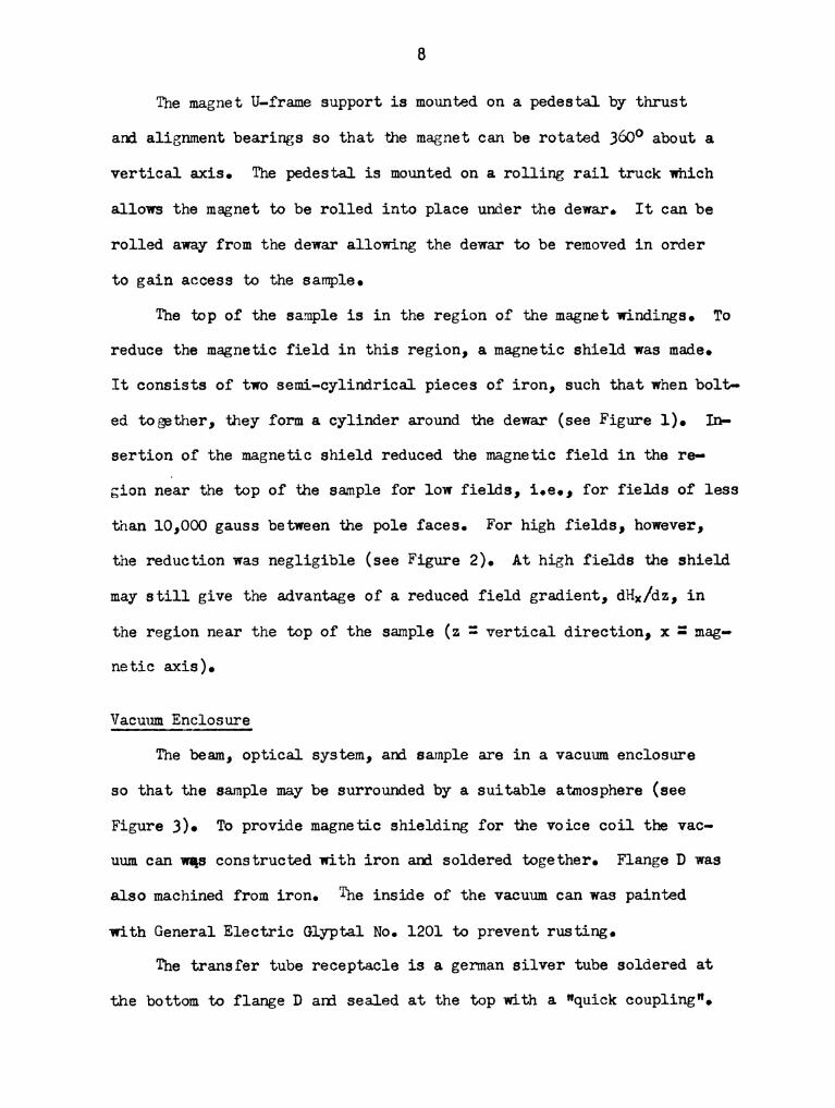
The magnet U-frame support is mounted on a pedestal by thrust
and alignment bearings so that the magnet can be rotated 360° about a
vertical axis. The pedestal is mounted on a rolling rail truck which
allows the magnet to be rolled into place under the dewar. It can be
rolled away from the dewar allowing the dewar to be removed in order
to gain access to the sample.
The top of the sample is in the region of the magnet windings. To
reduce the magnetic field in this region, a magnetic shield was made.
It consists of two semi-cylindrical pieces of iron, such that when bolt-
ed together, they form a cylinder around the dewar (see Figure 1). In-
sertion of the magnetic shield reduced the magnetic field in the re-
gion near the top of the sample for low fields, i.e., for fields of less
than 10,000 gauss between the pole faces. For high fields, however,
the reduction was negligible (see Figure 2). At high fields the shield
may still give the advantage of a reduced field gradient, de/dz, in
the region near the top of the sample (z - vertical direction, x = mag-’
netic axis).
Vacuum Enclosure
The beam, optical system, and sample are in a vacuum enclosure
so that the sample may be surrounded by a suitable atmosphere (see
Figure 3). To provide magnetic shielding for the voice coil the vac-
uum can was constructed with iron and soldered together. Flange D was
also machined from iron. The inside of the vacuum can was painted
'with General Electric Glyptal No. 1201 to prevent rusting.
The transfer tube receptacle is a german silver tube soldered at
the bottom to flange D and sealed at the top with a "quick coupling".


nouns l MAGNET SHIEID
MAGNET
YOKE
SAMPLE
/V SCALE:
3/16"=
1"
FACE
MAGNET
SHIELD
SUPPORT

10
U 3
53O
.1
——i
o'WITH SHIELD
o WITHOUT SHIEID o
3’
59
5°
‘é‘
§‘é
‘
[I
T
\\\
\'\\
\\
\
1I
_1
"a?
O
Magnetic
field
near
topof
sample
(gauss)
0 ' h,000 ' 8,000 12,000 16,000 _ 20,000
Magnetic field between pole faces (gauss)
1 FIGURE 2
EFFECT OF MAGNET SHIELD
NOTE: Measurements were made about 1 inch above and 1 inch
below the top of the sample.

11
VALVE
J)
WIRE
t_n
FEED
THRU} '
—_t
_
._.J
FLANGE'E;;7
RUBBER
STOPPER
QUICK
COUPLING
TRANSFER
——TUBE
RECEPTACLE
FLANGE D-
_'T]U
“—ml
0.',‘o
.
'. \' ."
eb. . . t._' _
«'53-. 2A 0' 0...,
- I} ,'-.". .
123' ‘. '1,“' '
FLANGE A —\a
EXHAUST PORT
LIJ
DEWAR
,1?
PYREX COLD FINGER
' o
SCALE: 1:2
1.3—1
FLANGE C
-—-FLANGE B
LEVELING
SCREW
KOVAR
_SEAL
l—Y
SUPPORT
ARM
GLASS WOOL
FTGURE 3 VACUWMCHGJ

12
The transfer tube is admitted through the transfer tube receptacle
without disturbing the atmosphere in the vacuum can. The transfer
tube receptacle can be sealed by inserting a rubber stopper.
The vacuum can, flange D, and flange C are held together with
screws and are sealed with two O—rings. The vacuum can is removable
so that the beam.and optical system may be adjusted. It is removed
by removing the screws holding it to flanges c and D, loosening the
"quick coupling", and then lifting the vacuum.can.
Flange B is held to flange D with screws and is sealed with an
O—ring. At the top of the cold finger there is a Kovar to Pyrex seal,
the Kovar being soldered to flange B. Experience has shown that the
cold helium gas rushing past a Kovar seal, when transferring liquid
helium, will cause the seal to fracture. To prevent this a thermal
insulator, made from stainless steel tubing and packed with glass wool,
proved successful. The top of the thermal insulator is slotted like
a bayonet type light bulb socket. Attached to flange B are two screws
which slide into the two slots in the thermal insulator so that the
insulator is attached to flange B by pushing up and then twisting the
thermal insulator. .
The three support arms and the dewar are bolted to flange A. A
leveling screw on the end of each support arm provides a means of
leveling, raising, and lowering the entire apparatus.
A two inch diameter exhaust port is provided for pumping on the
liquid helium.
Access to the sample is obtained by removing the dewar, thermal
insulator, and the cold finger.

13
Balance and Optical System
The 6 cm long beam is machined from 0.10 inch thick tempered alumi-
num (see Illustration 1 and Figure A). It is supported by a torsion
ribbon of Elgiloy (obtained from Elgin National watch Company), 0.001" x
0.100" x 1.625". The torsion constant of this ribbon is approximately
3,000 dyne-cm/radian. The beam.is restored to its null position by ad-
justing the current through the voice coil which is suspended from one
end of the beam into the gap of a PM speaker magnet. The top of the
voice coil also serves as a weight pan. Current to the voice coil is
supplied through two helical #hO wire leads. A change in current
through the voice coil of 0.025 microamperes, for a change in balance
load of one microgram, is required to restore the beam to null position.
Because of difficulty in placing weights on the weight pan without
disturbing the helical voice coil leads and the position of the voice
coil in the magnet air gap an accurate calibration of the voltage ver—
sus force was not carried out. Although the voice coil current was
expected to be linear with the force recent experience has shown that
this may not be so. Steps to correct this include: rearranging the
voice coil leads, reducing the number of turns on the voice coil, and
more careful placing of the voice coil in the magnet gap.
Position of the beam is detected by the position of a spot of
light focused on two cadmium selenide photo-conductive cells (Clairex
type h0hSL). The lens focuses an image of the filament of the light
bulb on the galvanometer mirror and in turn, the spherical galvanometer
mirror focuses an image of the slit on the two photo-cells (see Illus-
tration 2 and Figure 5). Current is supplied to the light bulb with a

I "I.
n1
n m TmI O N I BALANCE
......
....u{in}:mgnzfljw.fimfizfl.z&.cr=df.ks.:
1:.“
.47....
..r
4.O_;
..pm.
2
..3.....
17%
a4..
m.
V.
0...“..c.vh:
c}.
og
1..
ll
..
~..‘
-...ch....h.....
1' '.l.

FIGURE h ammo};
SPHERICALMIRROR
TORSIONRIBBON
VOICECOIL
LEADS
P.M.
SPEAKER
MNGNET
/
VOICECOIL
\
PYREX
SAMPLE
SUSPENSION
BALANCEADJUST
NUT
BEAM
VISCOUSDAMPER
TORSIONRIBBON
SUPPORT
YOKE
'
VIBRATION
ISOLATER
BRASS-
PLATE
BRASS
COUNTERWEIGHT
FLANGED
SCALE:
1:1
lS

' ILLUSTRATION II BALANCE AND OPTICAL

l7
i b?—
\
L A\ LIGHT BULB“" T
>— BAFFLES
d LENS
SLIT-IMAGE 4 LT/
/ /
L A
[1% L 1/[ii—t
L H\PHOTO-CELL
SECTION A-A /
SLIT
SP}TERICAL
r 7E70 ECJ
IOU)
FULL SCALE
FIGURE 5 OPTICAL srs'mu

18
PIREX TUBE
30mm WITH
CERROSEAIr-BS
——--——-——J
GERMAN SILVER YOK'E-C.
I
-C
‘I --m I‘ i/ SOLDERED
COPPER WIRE \
SAMPLE
SCALE: ~ 381
FIGURE 6
SAMPLE HOIDER

l9
BEAM END
SOIDERED
WIS]r
0.001 INCH THICK
PHOSPHOR-BRONZE
0.002 INCH DIAMETER
BERYLLIUM-COPPER
WIRE
_|
/
PHOSPHOR—BRONZE
RIBBON
SCALE: ~33).
FIGURE 7
IMPROVED BEAM END COUPLING

20
DC power supply having a stabilization factor of 2,000. When the slit-
image illuminates both photo-cells equally the beam is said to be in
null position.
The sample is suspended by a 1.5:mm diameter Pyrex tube. The sam-
ple is attached to the bottom of the tube with a copper wire which goes
through a small horizontal hole in the top of the sample and is solder-
ed at both ends to a german silver yoke (see Figure 6).
The Pyrex sample suspension tube and the voice coil are attached
to the beam ends by 0.75" x 0.10" x 0.001" phosphor bronze ribbons,
which are pinched in slots by tightening the #0-80 screws at the beam
ends. This was later found to be unsatisfactory as the stiffness of
the phosphor bronze ribbon increased the effective torsion constant of
the beam to about 30,000 dyne-cm/radian. After these experiments the
phosphor bronze ribbons were replaced by a yoke suspended by two 0.002
inch diameter wires (see Figure 7). This new suspension, less stiff
than the old, and placed so as to raise the center of mass of the beam
reduced the effective torsion constant of the beam to 1,000 dyne-cm/
radian.
A vane on the bottom of the beam.is immersed in glycerin to pro-
vide viscous damping of the beam.motion.
The beam and optical system are mounted on a brass plate which is
isolated from vibration with four rubber vibration mountings (Lord
# 106PL-2).
Electronics
The general features of the electronics are illustrated in
Figure 8 and the details in Figure 9 and Table I. The circuit is

21
DIFFERENTIAL IMPEDANCE
NETWORK 4- MATCHING .....—
AMPLIFIER
VARIABLE
4‘ 4—— CURRENT
fl SUPPLY
NULL CURRENT
DETECTOR DETECTOR
l
' vI
A —“
l
I V
I
é I
BEAM
<i><, ,
L/
VOICE COIL
FIGURE 8 SERVOSYSTEM

22
gy
_ — — — — _ _ — fl——_—
\
as"
CIRCUITFIGURE 9

Resistors
R1, R2
£3,310
R
122R7, R8, R9
1
R12
213 R1h, 1
R16 5
Capacitors
ClCg, C3
Batteries
Bl: B2
B3
Switches
51: S2
53: Sh
Transistor
Q
Photo-cells
P01, P02
Voice coil
VC
Ammeter
A
Null.Detector
NDl
Potentiometer
P
23
TABLE I
ELECTRICAL COMPONENTS
l K ohm 1% 1/2 watt wire wound precision
100 ohm helipot
300 K ohm helipot
10 K ohm helipot
200 ohm helipot
l K ohm 1% 1/8 watt. metal film
800 ohm 1% 1/8 watt metal film
100 ohm 1% l/2 watt wire wound precision
l K ohm 'wire wound potentiometer
39 K ohm 1% 1/8 watt metal film
22 K ohm 1% 1/8 watt metal film
300 mfd 10 WWDC
SO mfd 10 WVDC
Two series connected 6 VDC automobile batteries.
6 VDC automobile battery
DPST toggle switch
DPDT toggle switch
RCA type 2N2h7
Clairex type hOhSL
About 75 turns of #hO wire wound in one layer on an
aluminum foil form.
5 - 0 - 5 ma (zero center)
Leeds and Northrup DC microvolt amplifier, used on
1 - 0 - l mv (zero center) scale
Leeds and Northrup type K-3, used with a Rubicon
galvanometer, catologue no. 3&1? sensitivity
.005 a/mm

2h
almost identical to one used by Henry.2
Null detection is achieved by means of a Leeds and Northrup DC
microvolt amplifier attached across a Wheatstone bridge (called the in-
put bridge) which has two photo-cells on adjacent arms.
The DC component of the unbalance voltage goes directly across
another Wheatstone bridge (called the output bridge) which contains
the voice coil in one arm. This current through the voice coil in-
teracts with a PM speaker magnet partially restoring the beam to null
position. This restoring current adds a torsion constant of about
5,000 dyne-cm/radian to the effective mechanical torsion constant of
30,000 dyne-cm/radian; a negligible increase. An operational amplifier
is now being tried as a stage of amplification between the input bridge
and the output bridge in an effort to increase the electronic torsion
constant.
The unbalance voltage of the input bridge is also impressed across
a differential network, 03 and R16. This velocity dependent signal is
impressed on the base of the emitter follower connected transistor.
The transistor has a current gain of about 35 and affords impedance
matching between the differential network and the voice coil. Gain
is adjusted by R13 for most effective damping. A too high gain setting
results in an unstable system and the beam oscillates. The electronic
damping is effective in reducing oscillations of the beam caused by me-
chanical disturbances such as room vibrations and a varying magnetic
force on the sample.
2W. G. Henry, Private communication with the author, National
Iiesearch Council, Ottawa, Canada.

25
A constant current is supplied through the voice coil by battery,
82, connected across the output bridge. This current is adjustable
by means of the series connected potentiometers Rh, R5, and R6. The
current direction can be reversed with switch S3. The purpose of the
output bridge is to isolate the battery, B2, from the input bridge.
Current through the voice coil is measured roughly with the ammeter, A,
and accurately by measuring the voltage drop across the 100 ohm wire
wound resistor, R12, with a Leeds and Northrup type K—3 potentimeter,P.
The input bridge is balanced by replacing the photo-cells with two
matched resistors and adjusting R.3 until the null detector, NDl, reads
zero. This is done with 82 open and 31 closed. Likewise, the output
bridge is balanced by adjusting R10 for a zero reading on NDl with 32
closed and S1 open.
During an experiment the current through the voice coil was adjust-
ed with Rh’ R5, and R6 so that NDl would read zero with 51 and $2
closed and the voltage across R12 measured with the potentiometer.

IV DESCRIPTION OF EXPERIMENTS
The experiments that will be described were carried out using the
same bismuth crystal.
The rotational and absolute susceptibility experiments were done
to get the "feel" of the apparatus besides any useful data that might
come from them. The DHEVA experiment was done to test the utility of
the Gouy method in detecting DHFVA oscillation.
Because the balance was not calibrated the data presented is the
voltage drop across R12, called the restoring voltage, necessary to
balance out the magnetic force on the sample (see Figure 9). This
voltage is the difference between the voltage necessary to balance
the gravitational torque on the beam when the magnetic field is zero,
called the field-off voltage, and the voltage necessary to balance the
beam when the magnetic field is on, called the field—on voltage. Be-
cause the field—off voltage drifted at the rate of'about two microvolts
per minute it was necessary either to take a field—off voltage reading
between each field-on reading as done in the absolute susceptibility
experiment or to take field-off voltage readings at the beginning and
the end of the run and interpolate between by assuming a linear drift
with time as done in the rotational and DH+VA experiments.
The dial readings on the magnet current supply were calibrated
against the magnetic field with a Rawson type 820 rotating coil flux-
meter (see Table II). The magnet was cycled to about 18,000 gauss
two times before the calibration and before each series of measure-
26

27
TABLE II
MAGNET CALIBRATION WITH THREE INCH GAP
USING RAWSON TYPE 820 FLUXMETER
m
magnet current control measured magnetic field
dial readings (gauss)
Course Fine (field increasing) (field decreasing)
O 0 58 68
o 300 12h 135
O 500 --- 177
0 800 235 2&1
6 500 305 317
10 500 390 N10
23 500 682 700
35 500 951 967
h5 500 1,175 1,196
100 500 ---- 2,h30
135 500 3,196 3,21h
165 500 ----- 3,886
180 500 h,l97 8,220
2&0 500 5.550 5,561
330 500 7,559 7,577
390 500 8,881 8,912
500 500 11,268 11,296
650 500 lh,076 1h,100
800 500 16,061 16,090
1,000 500 17,685 ----
1,000 1,000 17,723 -—-—-
NOTE: The magnet was cycled to maximum field twice before
making the measurements.

28
ments. The increasing field values were used in the following experi-
ments 0
Absolute Susceptibility
Measurements were made on the crystal at room temperature with
the crystal in a vacuum and with the crystal in one atmosphere of
oxygen. The crystal was suspended from the beam with a 0.002 inch
diameter berylliumpcopper wire thereby allowing the sample to rotate
about the vertical axis. The sample could be seen to rotate when a
field of 100 gauss was applied and, therefore, the sample was assumed
to align itself with the direction of minimum (minimum absolute value
of $6) susceptibility in the plane of rotation along the direction of
the magnetic field.
One atmosphere of oxygen was admitted into the evacuated vacuum
can directly from the storage bottle. The pressure was measured with
a bellows-type gauge to an estimated accuracy of t0.5 inches of Hg.
Data from these measurements are presented in Tables VI and VII.
It can be seen from the voltage readings repeated at the same magnetic
field that the readings are reproducible to 30 microvolts making the
values‘for the restoring voltage with fields less than 2,000 gauss
meaningless. However, the error in the restoring voltage values at
17,685 gauss due to voltage measuring errors is only 0.02%.
The downward magnetic force, in dynes, acting on a cylindrical
sample of uniform cross sectional area, A, in a medium is
_ 2 IX
E’I'SI'n" (Xses’ xmem) (H12- HZ ) 2' ’
*
Refers to st - Vsm of Table III.

29
where the subscripts s and m.refer to the sample and the medium sur-
rounding the sample respectively,‘x.is the specific susceptibility,
e the density, H1 the field at the bottom of the sample, and H2 the
field at the top of the sample (values of Hz were estimated from
Figure 2). The subscript v replaces m when the medium is a vacuum.
In the case where the susceptibility is independent of the field
a plot of 3'versus (H12 - H22) is a line of constant slope. However,
the plot of restoring voltage versus (H12 - H22) is a line of decreas-
ing slope indicating a non-linear relation between the restoring volt-
age and the force on the sample (see Figure 10).
Using the above equation for the force the absolute susceptibility
of the sample may be calculated from
9m 33v
x=x — ——-——-S mes 3‘sf‘TSm
or if the restoring voltage is directly proportional to the magnetic
force
m
The calculations of 7‘s are tabulated in Table III using, 7§m ='106.2 x
10"6,l em 3 1.33 x 10'"3 g/cc,2 .98 = 9.86 g/cc.3
1Charles D. Hodgmen (ed.), Handbook of Chemistry and Physics
(hlst ed.), (Chemical Rubber PubIlshing Co., Cleveland, 1959), p. 2651.
2RobertW. Vance and W. M; Duke (eds.), Applied Cryogenic Engi-
' neering (John Wiley and Sons, New York, 1962), p.'hEO,IFig. A.6.
3H. M. Trent, D. E. Stone, and R. Bruce Lindsay (eds.), ”Density
of Solids," American Institute of Physics Handbook (lst ed.), (MCGrawh
Hill Book Company, New York, 19577, p. 2717.

FIGURE 10
EFFECT OF SURROUNDING THE SAMPLE WITH ONE ATMOSPHERE
OF OXYGEN ON THE RESTORING VOLTAGE,ROOM TEMPERATURE
0.20
II
rI
II
II
II
II
0018_
—-1
Line
of
constant
slope
—\\\\\\‘~
0016
"‘
8
001,4'—
9__
(91101)
0012'—
...
0010‘—
...
0.08
"'
——
co
eBeiton Butaoiseg
0Sample
in
one
atmosphere
0.0h“-
.////g
of
oxygen
_1
/0
Sample
in
avacuum
0.0
lL
ll
LI
Jl
I._
lI
J
o25
so
75
100
125
150
175
200
225
250
275
300
325
‘H12
-H22
(gauss2
x10'6)
3O

31
TABLE :LII
CALCULATIONS OF THE ABSOLUTE SUSCEPTIBILITY AT ROOM TEMPERATURE
Restoring Restoring Susceptibility
Field voltage voltage V v - V m X5
(gauss) st (volts) Vsm (volts) IvoltsT vsv/(st - Vsm) (cgs x 10
390 0.00008 0.00011 -0.00003 -2.60 -0.03
951 0.0005h 0.00052 0.0000h 11.2 0.16
1,175 0.0008u 0.00081 0.00003 31.0 0.hh
2,u10 0.00333 0.003h3 -0.00009 - 5.8 -0.51
3,196 0.00591 0.00601 -0.00010 -59.1 -0.85
3,860 0.00867 0.00883 -0.00015 -56.3 -O.81
u,197 0.01028 0.01036 -0.00012 -88.5 -l.27
5,550 0.0178h 0.01807 -0.00023 -78.3 -l.12
7.559 0.03302 0.033b9 -0.000h7 -70.h -1.01
8,881 0.08567 0.0t632 -o.00065 -69.8 -1.00
12,230 0.08578 0.08715 -0.001h2 -60.5 -O.87
1h,076 0.11066 0.11231 —0.00165 -67.1 -0.96
16,061 0.13972 0.1b167 —0.0019h -72.0 -1.03
17,685 0.16361 0.16592 -0.00232 -70.6 -1.01
aThe magnetic field at the
bThe voltage drop across R1
high field end of the sample.
required to balance the magnetic
force on the sample with the sample in a vacuum.
°The voltage drop across R12 required to balance the magnetic
force on the sample with the sample in one atmosphere of oxygen.
dThe specific susceptibility at room temperature calculated
frog X8 = Xm emvsv/ 98(st - Vsm), where Xm em/e s = 1.113 x
10- chO

32
Because the percentage error, due to the 30 microvolt uncertainty
in voltage measurements, in the value of st - V am is the smallest
(’w 2%) for the 17,685 gauss case; the susceptibility of the crystal
for the previously described orientation is thought to be -1.01 x 10"6
cgs 112%. The values of st and Vsm are so close that the non-linear-
ity of the balance has little effect on the above calculation.
Rotational Experiment
In an effort to determine the angle between the trigonal axis of
the crystal and the vertical two series of room temperature measurements
were made by rotating the magnet 190 degrees about a vertical axis in
15 degree steps. Measurements were made at fields of h,200 gauss and
11,270 gauss. The sample was suspended from the beam with a Fyrex tube
as described in the section, Balance and Optical System. The data from
these measurements are listed in Tables VIII, IX, X, and XI and plotted
in Figures 11 and 12.
At room temperature bismuth has two principal susceptibilities,
one parallel to the trigonal axis of X" = -1.053 x 10'“6 and the other
perpendicular to the trigonal axis of ?g_= -1.b82 x 10'6.h
If the trigonal axis, along 0? (see Figure 13), makes an angle
4) with the vertical and the magnetic field is in the x direction the
observed susceptibility is5
(Xusmzcb + xlcoszflcosze +X,SInze .
11L. F. Bates, Mbdern Magnetism (Cambridge Universtiy Press, London,
1961), p. 172.
Shaun, p. 173.

33
0°0116 I I I I I I I I I I I
0.01114 _ / /8- \O
—
'\
f, \ . DATA TAKEN 8-28-63 7,0.0112 -— / \O\ 0 DATA TAKEN 8-29-63 ‘1
/ \ °
2‘ 0.0110_. /(a "
3 d \0
e ‘I /, __/~I 0.0108 .
“
(D\
/
8° \ II:3. 0.0106——o \
. t , /
3° 0.010m- \ 7/ ‘ ‘I$4
.3 \ om
/,9 0.0102 -/ I
\ /
0.0100 - °\ /° “
\\ I /’
0.0098 -\9‘" . —‘
0.0096 1 I I I I I I ill I I l
to 20 0 -20 -h0 --60 ~80 ~100 -120 -1II0 -160
Magnet position (degrees)
FIGURE 11
DEPENDENCE OF RESTORINC VOLTAGE 0N MAGNET POSITION,
ROOM TEMPERATURE, 8,200 GAUSS

3h
$0790" I I I I I I I I I I
0.0780 -'_
. DATA TAKEN 8-28-63 /
0.0770 - 0 DATA TAKEN 8-29-63 9’ _
//
0.0760 *-/ _
J/
0.0750 *-55/ _
0007110 —T
l _.
/
/
\
/
0.0710 — \ . f/ _I
\ /
0.0700 L- ‘°' _
0 0690 ‘ 1 I I 1 J I I I I
' - 1.0 20 -20 -I.0 -60 -80 -100 -120 -lI.0 -160
Magnet position (degrees)
FIGURE 12
DEPENDENCE OF RESTORING VOLTAGE ON MAGNET POSITION,
ROOM TEMPERATURE, 11,270 GAUSS

35
N
I-9\/
'0
FIGURE 13
CRYSTAL ORIENTATION COORDINATES

36
TABLE IV
ORIENTATION OF THE TRIGONAL AXIS CALCULATED
FROM THE ROTATIONAL DATA
Minimtun Maximum 'X, min/x mat-x Angle a
Date Field voltage voltage 0
(gauss) mim (volts) max (volts) Vmim/vmax (degrees)
8-28-63 b.200 0.00980 0.01126 0.870 nu
8-29-63 u,200 0.00978 0.011u6 0.861 NS
8—28-63 11,270 0.06903 0.07788 0.887 36
8-29-63 11,270 0.07015 0.07780 0.902 3).;
a'The angle between the trigonal axis and the vertical calculated
from the data.

37
As the crystal is rotated about its vertical axis a maximum sus-
ceptibility, xmax ='-')(,‘L will be observed at O -'-' 90° and a minimum
susceptibility, xmin = X“ sin2¢ + '>(._L c0524), at 9 = 0°. The
ratio of these observed susceptibilities is
'X. Xnun n 2 ' 2
“max :LJ. 4) ¢
By using the above values for'Xfl and'Xl and the experimental values of
' Xmin/Xmax : Vmin/Vmax listed in Table IV, 4> can be found from
19110.: 2 2 = —O.276 smzct .Xmax 0.724 Slh ¢+COS 4) l
The value of ¢Iwas calculated to be h5° at h,200 gauss and 35° at 11,270
gauss (see Table IVL This calculation may be unreliable for the followb
ing reason. In the process of cutting the sample from the larger crys-
tal a small piece broke off the top of the sample. Crude measurements
showed that the angle between the normal to the surface of the break
and the vertical axis of the sample was 16° £20. If it is assumed
that the sample cleaved along the basal plane,6 then the trigonal axis
would make an angle of 16° with the vertical axis of the sample. This
assumption is borne out moreover by results described in the next sec-
tion.
Ferromagnetic contamination of the sample would make the measured
minimum susceptibility less (in absolute value) and would also decrease
the measured rotationd. values of x’min/ x’max’ the low field values
more than the high field values, thereby accounting qualitatively for
this descrepancy.
6Ibid., p. 171; .

38
De Haas-Van Alphen Effect
The crystal was suspended by the Pyrex tube as in the rotational
measurements and the magnet was rotated to the direction of maximum room
temperature susceptibility. In this orientation the magnetic field is
perpendicular to the trigonal axis of the crystal, i.e.,‘X.=Xmax= Xi .
The measurements were made at h.2°K.
The data from these measurements are listed in Table XII. The
low field at the top of the sample has been neglected as this decreases
the restoring voltage at 17,685 gauss by only 2% and less at lower
fields.
The restoring voltage, V, versus magnetic field curve (see Figure 1h)
clearly shows the quadratic rise in the restoring voltage. The oscilla-
tions can be seen more clearly in the plot of V/H2 versus H (see
Figure 15) and the plot of V/H2 versus l/H illustrates the periodic
variation in 1/H (see Figure 16). The double peak at 13,000 gauss is
attributed to spin Splitting of the Landau levels by Kunzler at al..7
Comparison of the position of the susceptibility peaks and the
period of the oscillations are compared with magnetothermal oscillations8
with the field along the binary axis of the crystal in Table V. The
Close agreement shown in Table V indicates that the field was nearly
parallel to the binary axis of the crystal when the susceptibility
measurements referred to in the preceding section were made.
7J. E. Kunzler, F. S. L. Hsu, and W} S. Boyle, Phys. Rev. III,
$32: 109A (1962).
81bid., p. 1090.

(Baton)
FIGURE 11;
eBquOA Butaoqseu
DEPENDENCE. OF RESTORING VOLTAGE ON THE MAGNETIC FIEID, h.2°x
°°2°
II
II
II
II
II
I
0.10-.
0.16-
0.1h-
0012
'-
0002—
'000000
39
0I
Jl
II
II
II
II
0.00
23
II5
67
89
10
11
12
13
magnetic
field
(gauss
x10'3)
to
Restoring voltage/field2 (volts/gaussz)
FIGURE 15
FIRED DEPENDENCE OF’DR-VA OSCILLATIONS, h.2°x
I II I I I I I I I I I I
n. O
. O
h- 0
I— . o
I— - ,
cith
._ Q
e——o—:%
——<>——
“’ o
~""“""——O
, O
IG_____L_____1 g) 1 I g) I I I I I I
gi 53 53 a: £3 E; a: £3 E3 85 23 £8 53a: no a: co co e~ c» c» r- r— xo ~o
12
13
1h
15
16
17
18
10
Magnetic
field
(gauss
x10'3)

FIGURE 16
880
-_
I i I I.
13 5% 53 E?Q Q m 00
I
O
m
p.
Restoring voltage/field2
I I
8 3I» N
(volts/gaussz)
I
O
N
N 700-
680-
Il
II
lL
l
120
1110
160
180
200
220
2110
260
Magnetic
field"1
(gauss"1
x106)
280
300
320
3110
360
380
1100
111

b2
TABLE V
COMPARISON OF SUSCEPTIBILITY
PEAKS AND MAGNETOTHERMAL PEAKS
Peak Susceptibility pe ks magnetothermal peaks
number Field H 10 /pH H 7 binary axis 10 /pH
p (gauss) (gauss)
13.750 15,500
1 ) 13,330 71.5 ) 67312,9u0 18,200
2 7,170 ~703 7,150 700
3 h, 800 693 14,720 703
b 3,610 693 3,750 700
5 2,850 701 --__. ---

V 'DISCUSSION
This work has successfully shown that the Gouy method is useful
for detecting De Haas-Van Alphen oscillations. Mereover, the method
has the advantage that the oscillations in free energy are measured
rather than those in susceptibility. Oscillations in metals should
readily be observable providing the sensitivity of the apparatus is
increased by an order of magnitude.
h3

IV BIBLIOGRAPHY
Bates, L. F. Modern Magnetism hth ed. Chambridge University Press,
Hodgmen, Charles D. (ed.). Handbook of Chemistry and Physics hlst ed.
Chemical Rubber Publishing Co., CIeveland, 1959.
Statton, J. A. Electricity and Magnetism. McGraw—Hill Book Company,
Trent, H. M., D. E. Stone, and R. Bruce Lindsay (eds.). "Density of
Solids," American Institute of Physics Handbook lst ed. McGrawa
Hill Book Company, New York, 1957.
Vance, Robert W} and W. M. Duke (eds.). Applied Cryogenic Engineer-
ing. John Wiley and Sons, New'York, 1962.
Chambers, R. 0. Can. J. Phys. 33, 1395,(1956).
Garber, ML, W. G. Henry, and H. G. Hoeve. Can. J. Phys. 28, 1595,
(1956).
Hedgcock, F. T. Rev. Sci. Inst. 31, 390,(1960).
Kunzler, J. E., F. S. L. Hsu, and W. S. Boyle. Phys. Rev. III, 138,
108b, (1962).
Shoenberg, D., and Zakie Uddin. Proc. Roy. Soc. 156, 701, (1935).
Shoenberg, D. Proc. Roy. Soc. 110, 3N1, (1939).

VII APPENDIX
1:5

86
TABLE VI
ABSOLUTE SUSCEPTIBILITT DATA, TAKEN AT ROOM
TEMPERATURE (22°C) WITH THE SAMPLE IN A VACUUM
Low fielda High fieldb H12 - H22 Voltagec Restoring
H2 H1 6 (volts) voltaged
(gauss) (gauss) (gauss2 x 10- ) (volts)
0 0 0 0.07886 —-———-.
0 0 0 0.07838 ------
0 390 0.152 0.07830 0.00008
0 0 0 0.07837 -—_-__-
0 951 0.908 0.07385 0.00058
0 O 0 000.7th "'-"""
0 1,175 1.380 0.07357 0.00088
0 0 0 0.07881 ------
0 2,810 5.808 0.07109 0.00333
0 0 0 0.07883 ~---------
0 3,196 10.21 0.06852 0.00591
0 0 0 0.07883 -----
0 3,860 1h.90 0.06578 0.00867
0 0 0 0.07881 _-—_——-
0 8,197 17.62 0.06816 0.01028
0 0 0 0.07839 -------
20 5,550 30.80 0.05657 0.01788
0 0 0 0.07883 ——-—~-
90 7,559 57.13 0.08180 0.03302
0 0 0 0.07882 -—-----
200 8,881 78.83 0.02875 0.08567
0 0 0 0.07881 ------
860 12,230 188.8 -0.01131 0.08578
0 0 0 0.07883 ---—--
1,320 18,076 196.h -0.03628 0.11066
0 0 0 0.07881 --—---
1,710 16,061 255.0 -0.00533 0.13972
0 0 0 0.07837 ----—--
2,220 17,685 307.8 —0.08928 0.16362
2,220 17,685 307.8 -0.08921 0.16359
0 0 0 0.07838 —————-
0 0 0 0.07837 -----__
aThe magnetic field at the low field end of the sample.
bThe magnetic field at the high field end of the sample.
0The voltage drop across R12 (see Figure 9 ) with the beam re-
stored to null position.
dThe voltage drop across R12 required to balance the magnetic
force on the sample.

87
TABLE VII
ABSOLUTE SUSCEPTIBILITT DATA, TAKEN AT ROOM TEMPERATURE
(22°C) WITH THE SAMPLE IN ONE ATMOSPHERE OF OXYGEN
Low field High field H12 - H22 Voltage Restoring
H2 H1 —6 (volts) voltage
(gauss) (gauss) (gauss2 x 10 ) (volts)
0 0 0 0.07186 --—-——-
0 390 0.152 0.07135 0.00011
0 0 0 0.07188 --—-—-
0 951 0.908 0.07092 0.00052
0 0 0 0.07188 —-----
0 1,175 1.380 0.07066 0.00081
0 O 0 0.07189 --—--
0 0 0 0.07187 ----
0 2,810 6.808 0.06807 0.00383
0 0 0 0.07153 -----
0 0 0 0.07151 -----
0 3,196 10.21 0.06550 0.00601
0 0 0 0.07150 ----
0 3,860 18.90 0.06268 0.00883
0 0 0 0.07150 ------
0 8,197 17.62 0.06116 0.01038
0 8,197 17.62 0.06113 0.01038
0 0 0 0.07150 ..--...-
20 5,550 30.80 0.05388 0.01807
0 0 0 0.07152 ---—-
90 7.559 57.13 0-03802 0.03389
0 0 0 0.07151 -----
0 0 0 0.07186 -—--—-
200 8,881 78.83 0.02518 0.08631
200 8,881 78.83 0.02512 0.08633
0 0 0 0.07188 -----
0 0 0 0.07188 -—---
860 12,230 188.8 —0.01570 0.08715
860 12,230 188.8 -0.01570 0.08715
0 0 0 0.07183 ----
0 0 0 0.07186 -----——
1,320 18,076 196.8 -0.08085 0.11231
0 0 0 0.07186 --—-—-
0 0 0 0.07183 -----
1,780 16,061 255.0 -0.07028 0.18167
0 0 0 0.07183 -----
0 0 0 0.07188 -----
2,220 17,685 307.8 -0.09888 0.16592
2,220 17,685 307.8 -0.09888 0.16592
0 0 0 0.07188 ----
NOTE: See TableVI footnotes for an explanation of the headings.

88
TABLE VIII
ROTATIONAL DATA, AT ROOM TEMPERATURE (22°c) AND AT
A FIELD OF 8,200 GAUSS, TAKEN AUGUST 28, 1963
Magnet . c Field-o Field~off Restoring
Timea positionb Fleld voltage voltagee voltage
(degrees) (gauss) Vl (volts) V2 (volts) V2 - V1 (volts)
7:82 80 0 -—--- 0.16158 ----——
7:87 80 0 -—--- 0.16165 --—--
7:89 80 0 ---- 0.16168 —
7:56 80 0 —-—.--- 0.16161 ----
8:00 80 8,200 0.15096 0.16166 0.01070
--- 25 8,200 0.15061 0.16167 0.01106
8:08 25 8.200 0.15065 0.16168 0.01103
8:08 10 8,200 0.15087 0.16169 0.01122
8:10 10 8,200 0.15086 0.16169 0.01123
---- -5 8,200 0.15089 0.16170 0.01121
8:18 -20 8,200 0.15068 0.16171 0.01103
8:25 —35 8,200 0.15108 0.16172 0.01068
--—- -50 8,200 0.15138 0.16173 0.01035
8:38 -50 8,200 0.15180 0.16178 0.01038
8:37 -65 8,200 0.15167 0.16175 0.01008
8:58 -80 8,200 0.15190 0.16179 0.00989
8:57 -95 8.200 0.15195 0.16180 0.00985
8:59 -95 8,200 0.15198 0.16180 0.00986
9:00 -110 8,200 0.15173 0,16180 0.01007
9:02 -110 8,200 0.15178 0,16181 0.01007
9:05 -125 8,200 0.15135 0.16181 0.01086
9:07 -125 8,200 0.15139 0.16182 0.01082
9:11 -180 8,200 0.15098 0.16183 0.01089
—-—— -155 8.200 0.15061 0.16183 0.01122
--—- -155 8.200 0.15060 0.16183 0.01123
---- -155 0 -—————— 0.16183 ——————
aThe time at which the reading of V1 or V2 was taken.
bThe position of the magnet relative to an arbitrarily picked
position.
cThe magnetic field at the high field end of the sample.
dThe voltage drop across R12 (see figuref?) with the field on
and the beam restored to null position.
8The voltage drop across R12 with the field off and the beam
restored to null position. As the "field-off" readings are taken on-
ly at the beginning and the end of a run; the values listed when the
field is on are obtained by assuming a linear drift with time.
fThe voltage drop across R12 required to balance the magnetic
force on the sample.

89
TABLE IX
ROTATIONAL DATA, AT ROOM TEMPERATURE (23°C) AND AT
A FIELD OF 8,200 GAUSS, TAKEN AUGUST 29, 1963
Magnet . Field-on Field—off Restoring
Time position Field voltage voltage voltage
(degrees) (gauss) V1 (volts) V2 (volts) V2 - V1 (volts)
6:01 —155 0 ---- 0.16339 -—-—-——
6:06 ~155 8,200 0.15231 0.16339 0.01108
6:07 -155 8,200 0.15236 0.16339 0.01103
6:09 -155 8,200 0.15238 0.16380 0.01102
6:11 -155 8,200 0.15288 0.16380 0.01096
6:15 -180 8,200 0.15277 0.16380 0.01063
6:19 -125 8.200 0.15313 0.16381 0.01028
——-- -110 8,200 0.15381 0.16381 0.01000
---- -95 8,200 0.15357 0.16381 0.00988
-—-- -80 8,200 0.15360 0.16381 0.00981
6:27 -80 8,200 0.15358 0.16382 0.00988
———- -80 8,200 0.15359 0.16382 0.00983
6:29 -65 8,200 0.15381 0.16382 0.01001
--- ~50 8,200 0.15293 0.16382 0.01089
--- -35 8,200 0.15255 0.16383 0.01088
6:81 -20 8,200 0.15227 0.16383 0.01116
7:00 -5 8.200 0.15210 0.16387 0.01137
7:01 -5 8,200 0.15205 0.16387 0.01182
7:03 -5 8,200 0.15205 0.16387 0.01182
7:05 10 8,200 0.15201 0.16388 0.01187
7:07 10 8,200 0.15205 0.16388 0.01183
7:09 10 8,200 0.15208 0.16388 0.01188
7:11 25 8.200 0.15218 0.16388 0.01130
-—- 25 8,200 0.15218 0.16389 0.01131
7:16 80 8,200 0.15258 0.16389 0.01091
-—-- 80 0 —-——.- 0.16389 --———-—
7:21 80 0 -—--- 0.16851 ---—--
NOTE: See TableVflIfootnotes for an explanation of the headings.

50
TABLE X
ROTATIONAL DATA, AT ROOM TEMPERATURE (22°C) AND AT
A FIELD OF 11,270 GAUSS, TAKEN AUGUST 28, 1963
magnet Field Field—on Field-off Restoring
Time position (gauss) voltage voltage voltage
(degrees) V1 (volts) V2 (volts) V2 - V1 (volts)
11:01 -155 0 -—-—-- 0.16199 -—--~-
11:03 -155 0 ------ 0.16201 —-———-
11:07 -155 11,270 0.08888 0.16201 0.07758
11:12 -180 11,270 0.08570 0.16202 0.07632
11:13 -180 11,270 0.08572 0.16202 0.07630
----- -125 11,270 0.08783 0.16202 0.07819
11:19 -110 11,270 0.09003 0.16203 0.07200
11:22 -95 11,270 0.09159 0.16203 0.07088
11:28 -80 11,270 0.09210 0.16208 0.06998
11:27 -65 11,270 0.09183 0.16208 0.07061
11:31 -50 11,270 0.08990 0.16205 0.07215
---—- -35 11,270 0.08789 0.16205 0.07816
---- -20 11,270 0.08608 0.16206 0.07598
----- -5 11,270 0.08878 0.16206 0.07732
11:83 10 11,270 0.08821 0.16207 0.07786,
11:88 10 11,270 0.08820 0.16207 0.07787
11:87 25 11,270 0.08866 0.16208 0.07782
11:53 80 11,270 0.08600 0.16209 0.07609
12:00 80 11,270 0.08616 0.16210 0.07598
12:08 80 0 --—-—- 0.16213 --——--
12:06 80 0 ---—-- 0.16209 —-———-
NOTE: See TableVUI footnotes for an explanation of the headings.

51
TABLE XI
ROTATIONAL DATA, AT ROOM TEMPERATURE (23°C) AND AT
A FIELD OF 11,270 GAUSS, TAKEN AUGUST 29, 1963
magnet Field Field—on Field-off Restoring
position ( ) voltage voltage voltage
(degrees) gauss Vi (volts) V2 (volts) V2 - Vi (volts)
8:85 80 0 ~--- 0.16358 ~---
8:50 80 0 ------ 0.16353 -----
8:56 80 11,270 0.08810 0.16360 0.07550
8:59 80 11,270 0.08808 0.16361 0.07557
5:01 25 11,270 0.08632 0.16362 0.07730
5:08 10 11,270 0.08583 0.16363 0.07780
5:07 ~50 11,270 0.08632 0.16365 0.07733
5:10 ~20 11,270 0.08762 0.16366 0.07608
--~~ ~20 11,270 0.08758 0.16367 0.07609
5:15 ~35 11,270 0.08951 0.16368 0.07817
5:19 ~50 11,270 0.09136 0.16369 0.07233
5:21 ~65 11,270 0.09292 0.16370 0.07078
5:23 ~80 11,270 0.09351 0.16371 0.07020
5:25 -95 11,270 0.09298 0.16371 0.07073
5:27 ~110 11,270 0.09138 0.16372 0.07238
5:31 ~125 11,270 0.08918 0.16378 0.07856
5:38 ~180 11,270 0.08703 0.16375 0.07672
-—-~ ~155 11,270 0.08625 0.16376 0.07751
5:83 ~155 0 -~~-~ 0.16378
NOTE: See Tablelefootnotes for an explanation of the headings.

TABLE
XII
DE
HAAS-VANALPHEN
EFFECTDATA
TAKENAT8.20K
Restori
Field-on
voltage
Field9
Field2
voltageb
Field-off
Timea
v1
(volts)
V2
(V0186)
(volts
(gaussx
10‘3)2
(v0
ts/gaussz)
(gauss‘
voltagec
72~v
HH2
)(gauss
x10'3)
7~7
)/H2
1H
(1
{x
106)
5:37
5:80
5:83
5:85
5:87
5:89
5:51
5:52
5:58
5:56
5:58
6:00
6:02
6:08
6:06
6:09
6:11
6:13
6:15
6:17
6:19
6:21
0.28828
0.28960
0.28906
0.28888
0.28859
0.28838
0.28797
0.28768
0.28725
0.28650
0.28635
0.28892
0.28867
0.28288
0.28256
0.28126
0.27896
0.28898
0.28897
0.28922
0.28920
0.28918
0.28922
0.28923
0.28923
0.28928
0.28925
0.28926
0.28927
0.28928
0.28929
0.28930
0.28931
0.28931
0.28932
0.28933
0.28938
0.28925
0.28936
...-u.“
“-0....-
.mn--.
----
0.00098
-0.00037
0.00017
0.00036
0.00066
0.00092
0.00130
0.00168
0.00208
0.00280
0.00296
0.00839
0.00865
0.00685
0.00678
0.00799
0.01080
ONOCDHMJNQON
mmv—quxowomm
O O O O
HHHHNNNNMMM
r-‘Ir-‘l
continued
on
next
page
56 O\O\
coco
O\
(I)
000
8*
Hfiwmeb-Ol‘dm
o o o o o 0
Hmmmwaxomomooo‘mmqm:
o o
OOOOOOOOOOHHNMM—d’mOCDChON
6280
-951
837
925
921
796
773
710
662
718
608
788
667
783
718
738
839
2530
1600
1600
1600
1180
930
771
658
563
505
853
812
379
388
325
303
288
52

6:23
6:28
6:27
6:28
6:31
6:33
6:38
6:36
6:38
6:82
6:85
6:86
6:88
6:51
6:53
6:57
6:59
7:01
7:03
7:05
7:07
7809
7:12
7:18
7:17
7:21
7823
7:28
0.27829
0.27809
0.27882
0.27662
0.27377
0.27016
0.26828
0.26850
0.26982
0.26831
0.26598
0.26317
0.25911
0.25527
0.25098
0.28688
0.28165
0.28100
0.28152
0.28221
0.28170
0.28066
0.23852
0.23631
0.23399
0.23097
0.23090
0.28937
0.28937
0.28938
0.28939
0.28980
0.28981
0.28981
0.28982
0.28983
0.28985
0.28986
0.28987
0.28987
0.28989
0.28950
0.28951
0.28952
0.28953
0.28958
0.28955
0.28956
0.28957
0.28958
0.28959
0.28960
0.28962
0.28962
0.28963
0.01108
0.01128
0.01096
0.01277
0.01563
0.01925
0.02113
0.02092
0.02001
0.02118
0.02388
0.02630
0.03036
0.03822
0.08263
0.08569
0.08788
0.08858
0.08803
0.08735
0.08787
0.08892
0.05107
0.05329
0.05563
0.05865
0.05873
TABLEXI[(continued)
3.75
3.75
3.97
8.23
h0h7
8.68
h089
5.13 Ngooommooommooomoooomm(x.
mgooommwmr-idxoooommb-QN—zt—fi
O
mmmooxoooo—b-b-Noooooooooommo:
HmeommmmnmmJ
O O O O O
:SAZUND-CDrifiW<)m>rifivo
HHHNNNNNMMM 82.3
51.6
58.
58.2
61.6
65.3
68.9
72.8
76.7
80.6
88.6
88.7
88.7
continued
on
next
page
788
802
695
718
782
879
883
795
698
678
693
721
770
810
851
883
886
878
838
780
725
695
672
666
661
657
661
662
267
267
252
236
228
218
205
195
186
179
172
166
159
158
189
188
139
135
131
127
128
121
117
118
111
109
106
106
53

7:26
7:28
7831
7833
7:35
7837
7839
7:81
7:88
7:86
7:89
7:51
7:58
7:56
8:01
8:08
8:06
8:09
8:13
8:16
8:18
8:21
8:28
8:28
8:31
8:33
8:36
8:38
0.22736
0.22381
0.22012
0.21596
0.21123
0.20695
0.20261
0.19818
0.19330
0.18818
0.18322
0.17830
0.16395
0.15869
0.18683
0.13778
0.12928
0.12323
0.11828
0.11387
0.11027
0.10781
0.10520
0.10358
0.10200
0.09972
0.09890
0.28965
0.28965
0.28966
0.28967
0.28968
0.28969
0.28969
0.28970
0.28971
0.28972
0.28978
0.28975
0.28976
0.28977
0.28979
0.28980
0.28981
0.28982
0.28988
0.28985
0.28986
0.28987
0.28989
0.28990
0.28992
0.28993
0.28998
0.28995
0.06228
0.06588
0.06958
0.07371
0.07885
0.08278
0.08708
0.09152
0.09681
0.10158
0.10652
0.11585
0.12581
0.13508
0.18296
0.15206
0.16057
0.16659
0.17160
0.17598
0.17959
0.18286
0.18869
0.18636
0.18792
0.18916
0.19022
0.19105
\OQHmmNmHmmNO—JQ
oO
o\o\c>c>c><><:r4r4.4r4cuFiririririririririri
o
N
H
H
o
m
H 13.5 wH—IOQHJOCD
O O O O O O O
mmmmxoooxo
HHHHHHHH
~:?\O
TABLEXII
(continued)
92.9
97.2
101
105
110
113
118
123
127
132
136
185
158
163
173
183
192
202
211
220
229
237
288
251
260
268
275
280
continued
onnext
page
670
677
686
699
716
727
737
787
759
772
788
796
818
828
828
831
835
823
815
801
785
770
756
783
722
706
693
680
108
101
99.3
97.8
95.5
93-7
92.0
90-3
88.7
87.2
85.8
83.1
80.6
78.3
76.1
73.9
72.1
70.3
68.9
67.5
66.1
65.0
68.0
63.1
62.0
61.1
60.8
59.7
58

8:81
8:85
8:87
8:50
8:52
8:55
8:58
9:03
9:05
9:06
9:08
9:15
0.09805
0.09781
0.09638
0.09637
0.09605
0.09891
0.28996
0.28998
0.28998
0.29000
0.29001
0.29002
0.29003
0.29050
0.29000
0.29007
0.29010
0.28972
0.19191
0.19257
0.19360
0.19363
0.19396
0.19856
0.19512
16.9
1701
17.2
17.3
17.8
17.5
17.6
00000
TABLEX11
(continued) 286
291
295
299
303
307
30900000
672
59.2
55
aThe
time
atwhich
the
reading
ofV1
orV
was
taken.
2
bThe
voltage
drop
across
R12
(see
figuref?)
with
the
field
on
and
the
beam
restored
to
null
position.
cThe
voltage
drop
across
R1
with
the
field
off
and
thebeam
restored
to
null
position.
As
the
"field-
off"
readings
are
taken
only
at
he
beginning
and
the
end
of
the
run;
the
values
listedwhen
the
field
is
on
are
obtainedbyassuminga
lineardriftwith
time.
dThe
voltage
drop
across
R12
required
to
balance
the
magnetic
force
on
the
sample.
8The
magnetic
field
at
the
high
field
and
of
the
sample.