Embed Size (px)
Citation preview

OPERATING & MAINTENANCEINSTRUCTIONS
GC0911
Mobile Gas HeaterModel No: MGH1
PART NO: 6920021

2
INTRODUCTIONThank you for purchasing this CLARKE Mobile Gas Heater.
This portable gas heater is designed to give safe, efficient and reliableoperation, and is for use with LPG/Butane gas only. Gas bottles are notsupplied with the unit, but are readily available from builders merchants orgas suppliers.
Before attempting to use the heater, please read this manual throughout andfollow the instructions carefully. Thoroughly familiarise yourself with thisproduct & its operation in order to ensure the safety of yourself and othersaround you. Henceforth, you can look forward to the heater giving you longand satisfactory service.
GUARANTEEThis product is guaranteed against faulty manufacture for a period of 12months from the date of purchase. Please keep your receipt which will berequired as proof of purchase. This guarantee is invalid if the product is foundto have been abused or tampered with in any way, or not used for it’sintended purpose.
Faulty goods should be returned to their place of purchase, no product canbe returned to us without prior permission. This guarantee does not effectyour statutory rights.
ENVIRONMENTAL PROTECTION
If disposing of this product or any damaged components, do notdispose of with general waste. Metal products should be taken to yourlocal civic amenity site for recycling of metal products.
PARTS AND SERVICING
For parts & Servicing, please contact your nearest dealer, orCLARKE International, on one of the following numbers.
PARTS & SERVICE TEL: 020 8988 7400PARTS & SERVICE FAX: 020 8558 3622
or e-mail as follows:PARTS: [email protected]
SERVICE: [email protected]

3
Please note that details and specifications contained herein, are correct at the time ofgoing to print. However, CLARKE International reserve the right to changespecifications at any time without prior notice.
1HGM
rebmuNtraP 1200296
thgieW gk8.8
)HxWxL(snoisnemiD mm537x053x024
leuF )elttobgk51(saGenatuB/GPL
noitpmusnoCsaGmumixaM H/g503
tupnIdetaRxaM )rh/utB05341(Wk2.4
sgnitteStaeH05341(Wk2.4-hgiH )rh/utB
8099(Wk9.2-deM )rh/utB6925(Wk55.1-woL )rh/utB
erutarepmeTgnitarepO C°04xaM/C°5niM
erusserPylppuS rabm82
noitanitseDfoseirtnuoC EI&BG
CONTENTSIntroduction ............................................................................................ 2
Guarantee .............................................................................................. 2
Environmental Protection ...................................................................... 2
Parts & Servicing .................................................................................... 2
Technical Specification ......................................................................... 3
General Safety Precautions .................................................................. 4
Carbon Monoxide Warning .................................................................. 5
Features of the MGH1 ............................................................................ 6
Installation .............................................................................................. 7
Heater Preparation ................................................................................ 8
Cleaning and Maintenance ............................................................... 11
Troubleshooting .................................................................................... 12
Parts Lists and Diagrams ..................................................................... 13
Declaration of Conformity .................................................................. 15
TECHNICAL SPECIFICATION

4
GENERAL SAFETY PRECAUTIONS1. ALWAYS read and ensure you fully understand the following precautions
and the hazards associated with this type of heater.
2. ALWAYS check for damage before using the heater. Check for breakageof parts and any other condition that may affect the function of theheater. Any damage should be properly repaired or the part replaced. Ifin doubt, DO NOT use. Consult your local dealer.
3. ALWAYS keep children and animals well away from heater at all times.
4. NEVER carry out any modifications to this product. If experiencing difficultyof any kind consult your local dealer.
5. NEVER move the heater when it is lit.
6. Use ONLY LPG/Butane gas. Ensure the gas bottle is correctly installed andcheck for leaks following replacement, using soapy water. NEVER use anaked flame to test for leaks.
7. ALWAYS ensure all gas hose and regulator connections are GAS TIGHT, andthe hose is not kinked.
8. NEVER use the heater where gasoline, paint thinner or other highlyflammable vapour or high dust content is present.
9. ONLY use in well ventilated areas. Provide a ventilation opening to fresh,outside air.
10. ALWAYS locate the heater on a stable, firm level surface.
11. ALWAYS ensure that ample ventilation is present if the heater is being litfollowing a long period without use.
12. Use heater in accordance with any applicable fire regulations.
13. NEVER use the heater in high-rise flats, in basements living or sleepingareas, in vehicles or caravans.
14. NEVER leave a heater, when lit, unsupervised - an individual should alwaysbe made responsible for monitoring it. Never leave the heater alight whilesleeping.
15. NEVER move, handle, replenish gas supply or service the heater when it ishot, or operating. Turn it off and wait for it to cool down first.
16. Use ONLY the regulator supplied with the heater.
17. ALWAYS ensure that the heater is correctly positioned as described onpage 7.
18 This heater will be hot when in operation and due care should be taken.
19. Never store gas cylinders any closer than 2 m from open drains, gullies oropenings to cellars. LPG is heavier than air and can collect at low levels.
20. Read these instructions carefully. Do not allow anyone who has not readthese instructions to light, adjust or operate this heater.

5
CARBON MONOXIDE WARNINGWARNING!
Lack of ventilation can cause Carbon Monoxide poisoning.Carbon Monoxide poisoning can kill.
Carbon Monoxide is a highly toxic, odourless, colourless and tasteless gas, createdby the incomplete combustion of carbon compounds due to a lack of availableoxygen in an enclosed space.
The signs of carbon monoxide poisoning are, headaches, dizziness and/ornausea. Should anyone show these signs, they must GET FRESH AIR IMMEDIATELY.Turn off the heater and have it serviced before using again.
Pregnant women, persons with a heart or lung condition, anaemia or under theinfluence of alcohol, or those living at high altitudes, are more likely to be effectedby carbon monoxide than others.
CARBON MONOXIDE ALARMSDue consideration should be given to the dangers of carbon monoxidepoisoning following incomplete combustion in an enclosed space. Carbonmonoxide detectors to BS EN 50291 are available for use in domesticpremises.
Where a new appliance is installed in a dwelling, a carbon monoxide alarmshould be provided in the room where the appliance is located.
Carbon monoxide alarms should comply with BS EN 50291:2001 and bepowered by a battery, designed to operate for the working life of the alarm.The alarm should incorporate a warning device to alert users when theworking life of the alarm is due to pass. Mains-powered BS EN 50291 Type Acarbon monoxide alarms with fixed wiring (not plug-in types) may be used asalternative applications, provided they are fitted with a sensor failure warningdevice.
The carbon monoxide alarm should be located in the same room as theappliance:
a. On the ceiling at least 300 mm from any wall or, if located on a wall, ashigh up as possible (above any doors and windows) but not within 150 mmof the ceiling; and
b. Between 1 m and 3 m horizontally from the appliance.
Note: Further guidance on the installation of carbon monoxide alarms isavailable in BS EN 50292:2002 and from manufacturers instructions. Provisionof an alarm should not be regarded as a substitute for correct use andregular servicing.

6
FEATURES OF THE MGH1 HEATERThe MGH1 gas heater comprises three groups of components:
GAS SUPPLY COMPONENTSThe gas supply to the machine is by means of a high pressure hose,connected to a gas cylinder, via a pressure regulator.
When the gas valve is opened, gas will flow to the control valve and finallythe burner. The heater can be operated at one of 3 settings using 1,2 or all 3burner plates.
This heater is designed only to be used with a 15 kg LPG/Butane gas bottle.Gas bottles are not supplied, but are readily available from builders mer-chants or gas suppliers etc.
The minimum surrounding air temperature rating for the heater is min 5oC -maximum +40oC.
IGNITION COMPONENTSAn igniter is positioned beside the Pilot Light. When the ignition button ispressed, a spark is generated which ignites the gas. Heat from the flame issensed by a thermocouple which is connected to the Flame Failure Valve. Asthe thermocouple heats up, a low voltage is fed to the Safety Cut-Off Valve,causing the valve to open, so that after a short period, the Control Valve (see‘Lighting the Heater’ on page 9) may be released, and the pilot flame isestablished.
SAFETY COMPONENTSThe heater incorporates the following safety devices that will cause it to shutdown in unsafe conditions.
The Flame Failure Valve will shut off the gas if the flame extinguishes for anyreason. When the thermocouple quickly cools down, the gas supply is shut offso that the heater will shut down automatically.
The Oxygen Depletion Sensor will shut off the gas if the CO2 concentration inthe air supply to the heater exceeds a pre-set value. The room should there-fore be well ventilated at all times.
The Anti-Tilt Switch will turn off the heater if it is tipped over. If this activates, setthe heater upright, check for obvious damage and wait 5-10 minutes beforeattempting to re-light the heater. This device may also operate if the heater Isknocked against or bumped.

7
INSTALLATIONWhen unpacking, check the heater for any damage that may have occuredin transit and notify your Clarke dealer immediately should any be apparent.
The only assembly required is to connect the gas supply. Do not attempt tooperate the heater with any gas other than LPG/Butane. You should havepurchased a suitable 15 kg gas bottle for use with this heater.
This heater, including the hose and regulator assembly, must be inspectedbefore each use and at least annually by a qualified service person. If thehose shows evidence of excessive wear or if the hose is cut, it must bereplaced prior to the heater being put into operation. The replacement hoseshall be that specified by Clarke International in the parts list on page 14.
POSITIONING THE HEATERThe heater must be located on a hard, flat, level surface to minimise the riskof accidental tipping and the gas bottle should be held by the bottle re-tainer. DO NOT operate this heater with the supply bottle in any other than theupright position.
The heater must be located such that it will not be exposed directly tosources of water. Use of this heater in a drafty area decreases its efficiency. Ifpossible, operate the unit in a draft free area.
MATERIAL CLEARANCESIt is recommended that the heater bepositioned with at least 500 mm clearanceto the sides and rear.
However, any household furnishings shouldbe a safe distance away as they could beadversely affected by heat.
Always position the heater facing the centreof the room and positioned as shown in thediagram. Never place objects on, or againstthe heater.
VENTILATIONThis heater must only be installed in a roomwhich is well ventilated. Do not operate in a caravan, boat, or any room ofless than 40 cu/m in volume. Ventilation is essential to reduce the dangers ofcarbon monoxide poisoning, and from oxygen depletion.
WARNING: IF FRESH, OUTSIDE AIR VENTILATION IS NOT PROVIDED,CARBON MONOXIDE POISONING COULD OCCUR.

8
Adequate ventilation should also considerably reduce the possibility ofcondensation occurring and lessen the dangers from the presence of anyundetected gas leakage. The following table shows the smallest sizes of roomsuitable for each heat setting and the ventilation which should be provided.
HEATER PREPARATION
INSTALLING THE BOTTLEThe connection to the gas bottle must be carried out in a well ventilatedarea, using the regulator and hose assembly supplied with the heater. DONOT attempt to adjust this regulator. It has been preset at the factory toprovide safe and correct operation.
1. Remove the bottle retainer fromthe back of the heater.
2. Fix the gas regulator to the gashose, securing it with thescrewed hose clip supplied.
3. Place the filled gas bottle intothe back of the heater with thevalve outlet facing outwards.
4. Connect the gas regulator ontothe outlet of the gas bottle usingthe integral clasp.
5. When attaching the regulator tothe gas cylinder ensure thebottle outlet is perfectly clean.
• Use compressed air if necessary to blow away any dust or dirt. Whenconnected, check for leaks using soapy water or liquid soap as describedbelow.
6. Secure the bottle with the bottle retainer.
TESTING FOR LEAKS:This must be carried out In a well ventilated area, free from any open flameor other sources of ignition. With the regulator connected to the cylinder,slowly turn on the regulator and proceed as follows:
cimarecforebmuNesunisrenrub eziSmooR
noitalitneV
leveLwoL leveLhgiH
1 m04 3 mc04 2 mc04 2
2 m07 3 mc07 2 mc07 2
3 m501 3 mc501 2 mc501 2

9
1. Brush all hose connections including pipe connections to the gas valve,regulator connection to the bottle and gas bottle valve with a 50:50solution of soap and water.
2. A stream of bubbles forming Is an indication of a leak. If a leak is found,turn off the valve on the regulator, disconnect the regulator from the gasbottle and remove the gas bottle to a cool, outdoor well-ventliated area.Contact your Clarke dealer or gas supplier for assistance.
DO NOT USE THE HEATER IF A LEAK IS FOUND.DO NOT USE A NAKED FLAMED FOR LEAK TESTING.DO NOT OPERATE ANY ELECTRICAL EQUIPMENT IN THE PRESENCE OF AGAS LEAK
3. After leak-testing is satisfactorily carried out and no leaks found, it may benecessary to twist the cylinder slightly to allow the regulator and hose to fitInside the heater casing without kinking the hose.
FITTING THE BATTERYThe ignitor battery and ignition button are supplied loose and require fitting.
1. Insert the battery into the socket and screw the ignition button into placein the top of the heater.
LIGHTING THE HEATERThe heater can be regulated to oneof three different heat settings: LOW,MEDIUM and HIGH. To light theheater:
1. Open the valve on the gasregulator.
2. Press down and turn the controlknob to LOW position.
• Do not release the control knob.
3. After 10 seconds press the ignitionbutton until the pilot light (at thebottom of the burner) ignites.
4. Continue to hold the control knobdown for 10-15 seconds afterignition. If the pilot flame goes outwhen releasing the button,repeat the above operation.
Note: The first time you use a newheater, it may be necessary to holdthe control knob down for a longertime in order to purge air from the system.

10
Once the heater is alight, turning the control knob to MEDIUM or HIGH willlight the second and third panel automatically.
4. When the heater is in operation, watch the pilot light and check that it isburning steadily. If it flickers or has a yellow flame, the heater should bechecked by your dealer.
5. Leave the heater burning at the LOW setting for approx 5 minutes beforeturning to a higher setting.
The heater can also be started at any of the 1 (LOW), 2 (MEDIUM) or 3 (HIGH)positions but this is not recommended.
CHANGING THE SETTING1. To select the desired heating level, press the control knob down slightly
and rotate until the knob locks at the desired position. Do not operatebetween the locked positions.
TURNING THE HEATER OFF1. Turn and press the control knob to the START position.
2. Turn off the regulator valve on the gas bottle, and if placing the heaterinto storage, disconnect the bottle.
CHANGING THE BOTTLEAlways allow the heater to cool down before removing and replacing thebottle. Never attempt to remove the regulator while the heater is operating.
Disconnect the gas regulator from the cylinder and remove the bottle afterreleasing the bottle retainer from the back of the heater.
POSSIBLE FAULTS ON STARTUP
THE HEATER DOESN'T LIGHT:• Defective ignitor battery failing to produce a spark. Replace battery.
• Check the gas bottle Is full. Removing and tilting the bottle should revealthe presence of LPG.
• Check the regulator Is properly attached to the bottle and the valve onthe regulator is turned on.
If this happens after the bottle has been changed, it could be:
• The bottle may have been excessively cold. Allow the bottle to reachroom temperature before attempting to start the heater.
• Air in the bottle. Hold the control knob down for a longer period of timeuntil the pilot and main burner light.
THE HEATER TURNS OFF BY ITSELF• If the heater turns off by itself after continuous working, repeat the lighting
operation, following the instructions faithfully.

11
• If it goes out soon after lighting, check for drafts or for the gas bottlerunning out of gas.
• If it goes out after about 30 minutes, it Is an indication that ventilation inthe room is inadequate. If so, the heater may have been shut off by theOxygen Depletion Sensor. Open a window or door to ventilate the roomand re-ignite.
CLEANING AND MAINTENANCE
WARNING: NEVER ATTEMPT TO SERVICE THE HEATER WHILE IT IS CON-NECTED TO THE GAS SUPPLY. ALLOW TO COOL BEFORE SERVICING.
CLEANING (annually or as required)1. Turn heater off and let cool down before cleaning.
2. Use a damp cloth wrung out in a solution of soapy water to clean theexterior and bottle storage area of the heater. Use household cleaners ondifficult spots.
3. Clean inside heater using compressed air where possible. Blow air backand forth along the entire burner face and ceramic plates until all dusthas been dislodged from surface. Take care not to knock the ceramicplates which can become fragile in use. Use compressed air to clean thepilot light opening and the gas outlets.
4. Wipe the heater completely dry before use, ensuring that no water getsinto the burners or pilot light area.
5. Never use abrasive cleaners as they may damage the paint finish.
GENERAL MAINTENANCE1. Inspect heater before bringing back into use. Check connections for leaks
by applying a mixture of liquid soap and water to hose connections. Anybubbles forming show a leak, which must be corrected before use.
2. Regularly check the flexible tubing between the regulator and heaterand replace if cracked. In the event of damage or broken components,replacements should only be obtained from Clarke Parts & Service.
3. Have the heater inspected yearly by a qualified service agent.
STORAGE1. For long term storage, always disconnect the bottle and store the heater
in a well ventilated area away from combustible materials. The bottle isbest kept in an outbuilding and preferably not in a basement or indoors.Cover the heater in its original packing and keep the unit dry and dustfree.
12
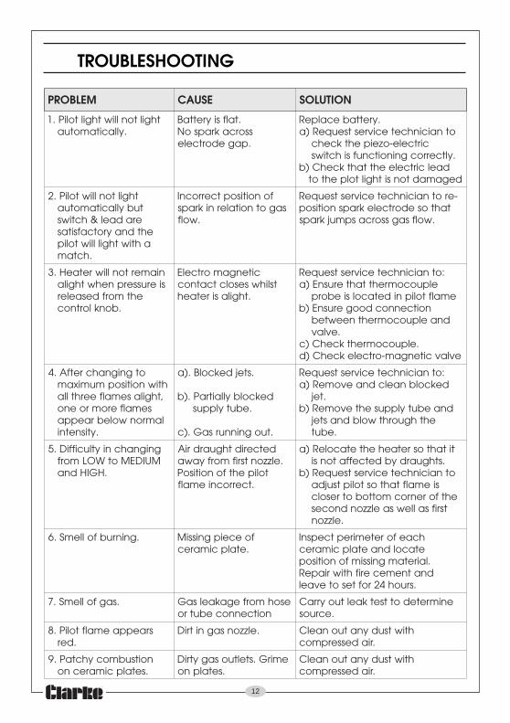
TROUBLESHOOTING
MELBORP ESUAC NOITULOS
thgiltonlliwthgiltoliP.1.yllacitamotua
.talfsiyrettaBssorcakrapsoN.pagedortcele
.yrettabecalpeRotnaicinhcetecivrestseuqeR)a
cirtcele-ozeipehtkcehc.yltcerrocgninoitcnufsihctiws
daelcirtceleehttahtkcehC)bdegamadtonsithgiltolpehtot
thgiltonlliwtoliP.2tubyllacitamotua
eradael&hctiwsehtdnayrotcafsitas
ahtiwthgillliwtolip.hctam
fonoitisoptcerrocnIsagotnoitalernikraps
.wolf
rotnaicinhcetecivrestseuqeR -etahtosedortcelekrapsnoitisop
.wolfsagssorcaspmujkraps
niamertonlliwretaeH.3sierusserpnehwthgila
ehtmorfdesaeler.bonklortnoc
citengamortcelEtslihwsesolctcatnoc
.thgilasiretaeh
:otnaicinhcetecivrestseuqeRelpuocomrehttahterusnE)a
emalftolipnidetacolsieborpnoitcennocdoogerusnE)b
dnaelpuocomrehtneewteb.evlav
.elpuocomrehtkcehC)cevlavcitengam-ortcelekcehC)d
otgnignahcretfA.4htiwnoitisopmumixam,thgilasemalfeerhtlla
semalferomroenolamronwolebraeppa
.ytisnetni
.stejdekcolB.)a
dekcolbyllaitraP.)b.ebutylppus
.tuogninnursaG.)c
:otnaicinhcetecivrestseuqeRdekcolbnaelcdnaevomeR)a
.tejdnaebutylppusehtevomeR)b
ehthguorhtwolbdnastej.ebut
gnignahcniytluciffiD.5MUIDEMotWOLmorf
.HGIHdna
detceridthguardriA.elzzontsrifmorfyawa
tolipehtfonoitisoP.tcerrocniemalf
titahtosretaehehtetacoleR)a.sthguardybdetceffatonsi
otnaicinhcetecivrestseuqeR)btsujda siemalftahtostolip
ehtforenrocmottobotresolctsrifsallewsaelzzondnoces
.elzzon
.gninrubfollemS.6 foeceipgnissiM.etalpcimarec
hcaeforetemireptcepsnIetacoldnaetalpcimarec
.lairetamgnissimfonoitisopdnatnemecerifhtiwriapeR
.sruoh42roftesotevael
.sagfollemS.7 esohmorfegakaelsaGnoitcennocebutro
enimretedottsetkaeltuoyrraC.ecruos
sraeppaemalftoliP.8.der
.elzzonsagnitriD htiwtsudynatuonaelC.riadesserpmoc
noitsubmocyhctaP.9.setalpcimarecno
emirG.steltuosagytriD.setalpno
htiwtsudynatuonaelC.riadesserpmoc

13
PARTS DIAGRAM

14
COMPONENT PARTS LIST
oN tsiLstraP oNtraP oN tsiLstraP oNtraP
1 ellirG 100HGMKZ 02 3epiPsaG 020HGMKZ
2 lenaProtcelfeR 200HGMKZ 12 elffaBlamrehT 120HGMKZ
3 redloHrenruB 300HGMKZ 22 reniateRelttoB 220HGMKZ
4 rosneSnoitelpeDnegyxO 400HGMKZ 32 evlaVlortnoCsaG 320HGMKZ
5 epiPgnitcennoC 500HGMKZ 42 tuNgniniateRretingI 420HGMKZ
6 redloH 600HGMKZ 52 lortnoCevlaV 520HGMKZ
7 ylbmessArenruBcimareC 700HGMKZ 62 tuNgniniateRevlaV 620HGMKZ
8 )trohs(rotcennoCrotcejnI 800HGMKZ 72 retingInottub-hsuP 720HGMKZ
9 )gnol(rotcennoCrotcejnI 900HGMKZ 82 bonKlortnoC 820HGMKZ
01 lenaPtnorFtenibaC 010HGMKZ 92 tessuGelgnA 920HGMKZ
11 troppuStliT-itnA 110HGMKZ 03 draoBkcaBrenruB 030HGMKZ
21 hctiwStliT-itnA 210HGMKZ 13 ylbmessAthgiLtoliP 130HGMKZ
31 ydoBtenibaC 310HGMKZ 23 esoHelbixelF 230HGMKZ
41 esaBtenibaC 410HGMKZ 33 pilCeelibuJ 330HGMKZ
51 leehWrotsaC 510HGMKZ 43 elpuoc-omrehT 430HGMKZ
61 elbaCnoitingI 610HGMKZ 53 yrettaBAAA 530HGMKZ
71 elbaClortnoCevlaV 710HGMKZ 63 rotalugeRsaG 630HGMKZ
81 1epiPsaG 810HGMKZ 73 gnirpS 730HGMKZ
91 2epiPsaG 910HGMKZ 83 paCrotingI 830HGMKZ

15
DECLARATION OF CONFORMITY