Embed Size (px)
Citation preview

Web: www.bonitron.com ● Tel: 615-244-2825 ● Email: [email protected]
Model M3484
Industrial Line Noise Filter Module
Customer Reference Manual

Bonitron, Inc.
2
Bonitron, Inc. Nashville, TN
An industry leader in providing solutions for AC drives.
ABOUT BONITRON
Bonitron designs and manufactures quality industrial electronics that improve the reliability of processes and variable frequency drives worldwide. With products in numerous industries, and an educated and experienced team of engineers, Bonitron has seen thousands of products engineered since 1962 and welcomes custom applications.
With engineering, production, and testing all in the same facility, Bonitron is able to ensure its products are of the utmost quality and ready to be applied to your application.
The Bonitron engineering team has the background and expertise necessary to design, develop, and manufacture the quality industrial electronic systems demanded in today’s market. A strong academic background supported by continuing education is complemented by many years of hands-on field experience. A clear advantage Bonitron has over many competitors is combined on-site engineering labs and manufacturing facilities, which allows the engineering team to have immediate access to testing and manufacturing. This not only saves time during prototype development, but also is essential to providing only the highest quality products.
The sales and marketing teams work closely with engineering to provide up-to-date information and provide remarkable customer support to make sure you receive the best solution for your application. Thanks to this combination of quality products and superior customer support, Bonitron has products installed in critical applications worldwide.

Bonitron, Inc.
3
AC DRIVE OPTIONS
In 1975, Bonitron began working with AC inverter drive specialists at synthetic fiber plants to develop speed control systems that could be interfaced with their plant process computers. Ever since, Bonitron has developed AC drive options that solve application issues associated with modern AC variable frequency drives and aid in reducing drive faults. Below is a sampling of Bonitron’s current product offering.
WORLD CLASS PRODUCTS
Undervoltage Solutions
Overvoltage Solutions
Uninterruptible Power for Drives (DC Bus Ride-Thru) Voltage Regulators
Chargers and Dischargers Energy Storage
Braking Transistors Braking Resistors
Transistor/Resistor Combo Line Regeneration
Dynamic Braking for Servo Drives
Common Bus Solutions
Portable Maintenance Solutions
Single Phase Power Supplies 3-Phase Power Supplies
Common Bus Diodes
Capacitor Formers
Capacitor Testers
Power Quality Solutions
Green Solutions
12 and 18 Pulse Kits
Line Regeneration

Model M3484
4
This page intentionally left blank.
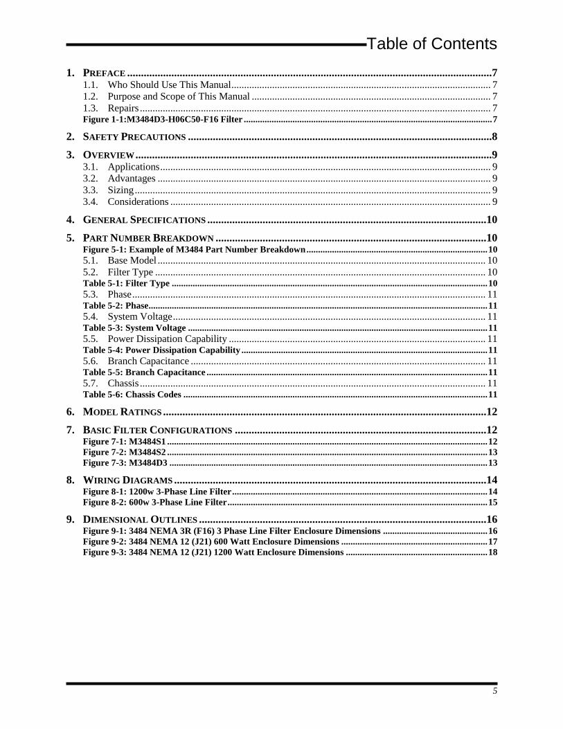
Table of Contents
5
1. PREFACE ....................................................................................................................................7 1.1. Who Should Use This Manual ...................................................................................................... 7 1.2. Purpose and Scope of This Manual .............................................................................................. 7 1.3. Repairs .......................................................................................................................................... 7 Figure 1-1:M3484D3-H06C50-F16 Filter ........................................................................................................... 7
2. SAFETY PRECAUTIONS ..............................................................................................................8
3. OVERVIEW .................................................................................................................................9 3.1. Applications .................................................................................................................................. 9 3.2. Advantages ................................................................................................................................... 9 3.3. Sizing ............................................................................................................................................ 9 3.4. Considerations .............................................................................................................................. 9
4. GENERAL SPECIFICATIONS .....................................................................................................10
5. PART NUMBER BREAKDOWN ..................................................................................................10 Figure 5-1: Example of M3484 Part Number Breakdown .............................................................................. 10 5.1. Base Model ................................................................................................................................. 10 5.2. Filter Type .................................................................................................................................. 10 Table 5-1: Filter Type ........................................................................................................................................ 10 5.3. Phase ........................................................................................................................................... 11 Table 5-2: Phase .................................................................................................................................................. 11 5.4. System Voltage ........................................................................................................................... 11 Table 5-3: System Voltage ................................................................................................................................. 11 5.5. Power Dissipation Capability ..................................................................................................... 11 Table 5-4: Power Dissipation Capability .......................................................................................................... 11 5.6. Branch Capacitance .................................................................................................................... 11 Table 5-5: Branch Capacitance ......................................................................................................................... 11 5.7. Chassis ........................................................................................................................................ 11 Table 5-6: Chassis Codes ................................................................................................................................... 11
6. MODEL RATINGS .....................................................................................................................12
7. BASIC FILTER CONFIGURATIONS ...........................................................................................12 Figure 7-1: M3484S1 .......................................................................................................................................... 12 Figure 7-2: M3484S2 .......................................................................................................................................... 13 Figure 7-3: M3484D3 ......................................................................................................................................... 13
8. WIRING DIAGRAMS .................................................................................................................14 Figure 8-1: 1200w 3-Phase Line Filter .............................................................................................................. 14 Figure 8-2: 600w 3-Phase Line Filter ................................................................................................................ 15
9. DIMENSIONAL OUTLINES ........................................................................................................16 Figure 9-1: 3484 NEMA 3R (F16) 3 Phase Line Filter Enclosure Dimensions ............................................. 16 Figure 9-2: 3484 NEMA 12 (J21) 600 Watt Enclosure Dimensions ............................................................... 17 Figure 9-3: 3484 NEMA 12 (J21) 1200 Watt Enclosure Dimensions ............................................................. 18

Model M3484
6
This page intentionally left blank.

User’s Manual
7
1. PREFACE
WHO SHOULD USE THIS MANUAL 1.1.
This manual is intended for use by anyone who is responsible for integrating, installing, maintaining, troubleshooting, or using this equipment with any AC Drive System.
Please keep this manual for future reference.
PURPOSE AND SCOPE OF THIS MANUAL 1.2.
This manual is a user’s guide for the Model M3484 Industrial Line Noise Filter Module. It will provide the user with the necessary information to successfully install, integrate, and use the M3484 module in a Variable Speed AC Drive system.
In the event of any conflict between this document and any publication and/or documentation related to the AC drive system, the latter shall have precedence.
REPAIRS 1.3.
Repairs or modifications to this equipment are to be performed by Bonitron approved personnel only. Any repair or modification to this equipment by personnel not approved by Bonitron will void any warranty remaining on this unit.
Figure 1-1:M3484D3-H06C50-F16 Filter
Model M3484
8
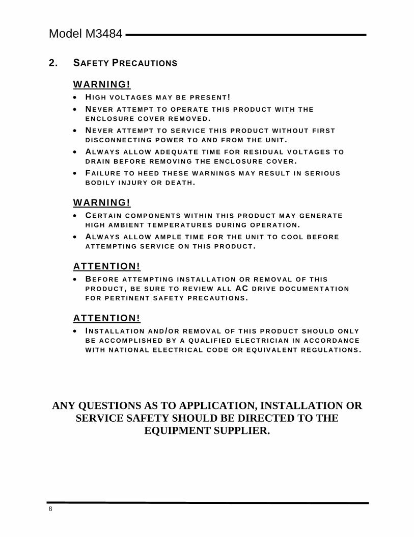
2. SAFETY PRECAUTIONS
WARNING!
H I G H V O L T AG E S M A Y B E P R E S E N T !
N E V E R AT T E M P T T O O P E R AT E T H I S P R O D U C T W I T H T H E
E N C L O S U R E C O V E R R E M O V E D .
N E V E R AT T E M P T T O S E R V I C E T H I S P R O D U C T W I T H O U T F I R S T
D I S C O N N E C T I N G P O W E R T O AN D F R O M T H E U N I T .
AL W AY S AL L O W AD E Q U AT E T I M E F O R R E S I D U AL V O L T AG E S T O
D R AI N B E F O R E R E M O V I N G T H E E N C L O S U R E C O V E R .
F AI L U R E T O H E E D T H E S E W AR N I N G S M A Y R E S U L T I N S E R I O U S
B O D I L Y I N J U R Y O R D E A T H .
WARNING!
C E R T AI N C O M P O N E N T S W I T H I N T H I S P R O D U C T M AY G E N E R AT E
H I G H AM B I E N T T E M P E R A T U R E S D U R I N G O P E R AT I O N .
AL W AY S AL L O W AM P L E T I M E F O R T H E U N I T T O C O O L B E F O R E
AT T E M P T I N G S E R V I C E O N T H I S P R O D U C T .
ATTENTION!
B E F O R E AT T E M P T I N G I N S T AL L AT I O N O R R E M O V AL O F T H I S
P R O D U C T , B E S U R E T O R E V I E W AL L AC D R I V E D O C U M E N T A T I O N
F O R P E R T I N E N T S A F E T Y P R E C AU T I O N S .
ATTENTION!
I N S T AL L AT I O N AN D /O R R E M O V AL O F T H I S P R O D U C T S H O U L D O N L Y
B E AC C O M P L I S H E D B Y A Q U AL I F I E D E L E C T R I C I A N I N AC C O R D AN C E
W I T H N AT I O N AL E L E C T R I C AL C O D E O R E Q U I V AL E N T R E G U L AT I O N S .
ANY QUESTIONS AS TO APPLICATION, INSTALLATION OR
SERVICE SAFETY SHOULD BE DIRECTED TO THE
EQUIPMENT SUPPLIER.

User’s Manual
9
3. OVERVIEW Bonitron's Model M3484 line filters are designed to be used in applications where power electronic devices experience problems from line harmonics, capacitor switching transients and DC drive notching. Typically, devices with these problems have Over Voltage faults. Usually, the problems are more severe when the devices are in a standby or lightly loaded mode. For this reason, chokes alone are unable to filter the transients.
The Bonitron M3484 modules are composed of resistor, diode, and capacitive elements offering very good electrical damping of continuous and intermittent transients. Each device includes 2 parallel filters, one which dampens over voltage events and the other which dampens under voltage events. The transient/harmonic energy is dissipated in the resistors. The units are protected by a combination of fusing and thermal protection via three phase contactor.
The devices require some impedance (at least 5%) between the noise source and their point of installation for proper filtering. Usually, existing AC chokes or system transformers provide this impedance.
APPLICATIONS 3.1.The Model M3484 Line Filter is commonly used on applications involving:
VFD installations where DC drives in close proximity are causing line notching
VFD installations where high frequency carrier waveforms or other continuous oscillations are superimposed on the local power grid
VFD installations where the three phase power is coupled by brushes or other means to the VFD (ex. Overhead cranes)
ADVANTAGES 3.2.
Unlike capacitive filters, these modules filter without shifting the resonant frequency of the electrical system.
The modules provide additional system Kvar for power factor correction and KVA demand reduction
SIZING 3.3.Proper filter sizing is critical to operation. Consult Bonitron engineering for assistance.
Modules are available for standard line voltages.
Modules are selected based on resistive watts required to dissipate the disturbance.
Modules may be paralleled for additional dissipation.
CONSIDERATIONS 3.4.
Possible sources of disturbing noise
Physical distances to possible noise sources
Harmonic Distortion Level
Electrical transformations between filter and noise sources
Transformer Impedance
Model M3484
10
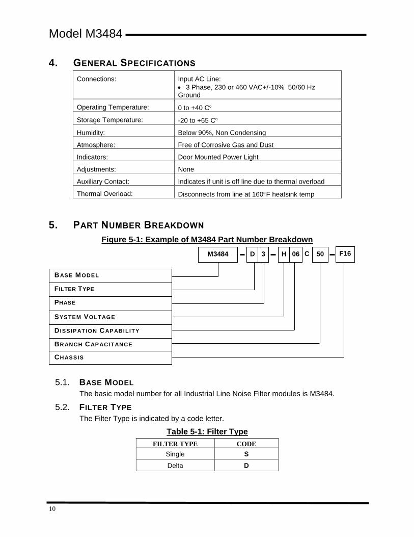
4. GENERAL SPECIFICATIONS
Connections: Input AC Line:
3 Phase, 230 or 460 VAC+/-10% 50/60 Hz Ground
Operating Temperature: 0 to +40 C
Storage Temperature: -20 to +65 C
Humidity: Below 90%, Non Condensing
Atmosphere: Free of Corrosive Gas and Dust
Indicators: Door Mounted Power Light
Adjustments: None
Auxiliary Contact: Indicates if unit is off line due to thermal overload
Thermal Overload: Disconnects from line at 160F heatsink temp
5. PART NUMBER BREAKDOWN
Figure 5-1: Example of M3484 Part Number Breakdown
BASE MODEL 5.1.
The basic model number for all Industrial Line Noise Filter modules is M3484.
FILTER TYPE 5.2.
The Filter Type is indicated by a code letter.
Table 5-1: Filter Type
FILTER TYPE CODE
Single S
Delta D
BASE MODEL
FILTER TYPE
PHASE
SYSTEM VOLTAGE
D ISSIPATION CAP ABILITY
BR ANCH CAP ACITANCE
M3484 D C 50
CH ASSIS
F16 3 H 06
User’s Manual
11
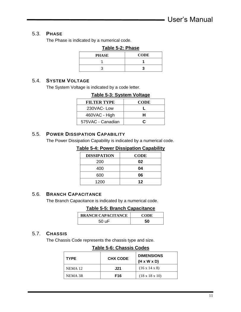
PHASE 5.3.
The Phase is indicated by a numerical code.
Table 5-2: Phase
PHASE CODE
1 1
3 3
SYSTEM VOLTAGE 5.4.
The System Voltage is indicated by a code letter.
Table 5-3: System Voltage
FILTER TYPE CODE
230VAC- Low L
460VAC - High H
575VAC - Canadian C
POWER DISSIPATION CAPABILITY 5.5.
The Power Dissipation Capability is indicated by a numerical code.
Table 5-4: Power Dissipation Capability
DISSIPATION CODE
200 02
400 04
600 06
1200 12
BRANCH CAPACITANCE 5.6.
The Branch Capacitance is indicated by a numerical code.
Table 5-5: Branch Capacitance
BRANCH CAPACITANCE CODE
50 uF 50
CHASSIS 5.7.
The Chassis Code represents the chassis type and size.
Table 5-6: Chassis Codes
TYPE CHX CODE DIMENSIONS
(H x W x D)
NEMA 12 J21 (16 x 14 x 8)
NEMA 3R F16 (18 x 18 x 10)

Model M3484
12
6. MODEL RATINGS
FILTER PHASES INPUT
VOLTS DISSIPATION
BRANCH
CAPACITANCE
KVAR
@60
HZ
FUSE
AMPS MODEL NUMBER
Single 1 230 200 50 uF 1 15 M3484S1-L02C50
Single 1 460 200 50 uF 4 15 M3484S1-H02C50
Single 1 230 400 50 uF 2 35 M3484S2-L04C50
Single 1 460 400 50 uF 8 35 M3484S2-H04C50
Delta 3 230 600 50 uF 3 30 M3484D3-L06C50
Delta 3 460 600 50 uF 12 30 M3484D3-H06C50
Delta 3 230 1200 50 uF 3 40 M3484D3-L12C50
Delta 3 460 1200 50 uF 12 40 M3484D3-H12C50
Delta 3 575 600 50 uF 19 40 M3484D3-C06C50
7. BASIC FILTER CONFIGURATIONS
Figure 7-1: M3484S1

User’s Manual
13
Figure 7-2: M3484S2
Figure 7-3: M3484D3

Model M3484
14
8. WIRING DIAGRAMS
Figure 8-1: 1200w 3-Phase Line Filter
Dwg: 040141 Rev: 20071009

User’s Manual
15
Figure 8-2: 600w 3-Phase Line Filter
Dwg: 040140 Rev: 20071009

Model M3484
16
9. DIMENSIONAL OUTLINES
Figure 9-1: 3484 NEMA 3R (F16) 3 Phase Line Filter Enclosure Dimensions
Dwg: 060197 Rev: 20060728

User’s Manual
17
Figure 9-2: 3484 NEMA 12 (J21) 600 Watt Enclosure Dimensions
Dwg: 070275 Rev: 20071009

Model M3484
18
Figure 9-3: 3484 NEMA 12 (J21) 1200 Watt Enclosure Dimensions
Dwg: 070276 Rev: 20071009


D3484_CMAN_VALL_00d 04/04/2014
521 Fairground Court ● Nashville, TN 37211 ● USA
Tel: (615) 244-2825 ● Fax: (615) 244-2833 ● Web: www.bonitron.com ● Email: [email protected]