Embed Size (px)
Citation preview
- 1 -
MODELS PDR-1000AN & PDR-1200S
PERSONAL DATARAM PARTICULATE MONITORING
INSTRUCTION MANUAL P/N (tba)
THERMO ELECTRON CORPORATION ENVIRONMENTAL INSTRUMENTS
27 FORGE PARKWAY FRANKLIN MASSACHUSETTS 02038
(866) 282-0430 Toll Free (508) 520-0430 International
(508) 520-1460 Fax
www.thermo.com/ih
REVISED: January 2004 ORIGIN: APRIL 2000

- 2 -
© 2003 Thermo Electron Corporation. All rights reserved. Thermo Electron Corporation, question
everything, and Analyze. Detect. Measure. Control are trademarks of Thermo Electron Corporation.
All other product names and logos are the property of their respective owner.
Specifications, terms and pricing are subject to change. Not all products are available in all countries.
Please consult your local sales representative for details.
- 3 -
WARRANTY
Seller warrants that the Products will operate substantially in conformance with Seller's published specifications, when subjected to normal, proper and intended usage by properly trained personnel, for 13 months from date of installation or 12 months from date of shipment, whichever is less (the "Warranty Period"). Seller agrees during the Warranty Period, provided it is promptly notified in writing upon the discovery of any defect and further provided that all costs of returning the defective Products to Seller are pre-paid by Buyer, to repair or replace, at Seller's option, defective Products so as to cause the same to operate in substantial conformance with said specifications. Replacement parts may be new or refurbished, at the election of Seller. All replaced parts shall become the property of Seller. Shipment to Buyer of repaired or replacement Products shall be made in accordance with the provisions of Section 5 above. Lamps, fuses, bulbs and other expendable items are expressly excluded from the warranty under this Section 8. Seller's sole liability with respect to equipment, materials, parts or software furnished to Seller by third party suppliers shall be limited to the assignment by Seller to Buyer of any such third party supplier's warranty, to the extent the same is assignable. In no event shall Seller have any obligation to make repairs, replacements or corrections required, in whole or in part, as the result of (i) normal wear and tear, (ii) accident, disaster or event of force majeure, (iii) misuse, fault or negligence of or by Buyer, (iv) use of the Products in a manner for which they were not designed, (v) causes external to the Products such as, but not limited to, power failure or electrical power surges, (vi) improper storage of the Products or (vii) use of the Products in combination with equipment or software not supplied by Seller. If Seller determines that Products for which Buyer has requested warranty services are not covered by the warranty hereunder, Buyer shall pay or reimburse Seller for all costs of investigating and responding to such request at Seller's then prevailing time and materials rates. If Seller provides repair services or replacement parts that are not covered by the warranty provided in this Section 8, Buyer shall pay Seller therefore at Seller's then prevailing time and materials rates. ANY INSTALLATION, MAINTENANCE, REPAIR, SERVICE, RELOCATION OR ALTERATION TO OR OF, OR OTHER TAMPERING WITH, THE PRODUCTS PERFORMED BY ANY PERSON OR ENTITY OTHER THAN SELLER WITHOUT SELLER'S PRIOR WRITTEN APPROVAL, OR ANY USE OF REPLACEMENT PARTS NOT SUPPLIED BY SELLER, SHALL IMMEDIATELY VOID AND CANCEL ALL WARRANTIES WITH RESPECT TO THE AFFECTED PRODUCTS. THE OBLIGATIONS CREATED BY THIS SECTION TO REPAIR OR REPLACE A DEFECTIVE PRODUCT SHALL BE THE SOLE REMEDY OF BUYER IN THE EVENT OF A DEFECTIVE PRODUCT. EXCEPT AS EXPRESSLY PROVIDED IN THIS SECTION 8, SELLER DISCLAIMS ALL WARRANTIES, WHETHER EXPRESS OR IMPLIED, ORAL OR WRITTEN, WITH RESPECT TO THE PRODUCTS, INCLUDING WITHOUT LIMITATION ALL IMPLIED WARRANTIES OF MERCHANTABILITY OR FITNESS FOR ANY PARTICULAR PURPOSE. SELLER DOES NOT WARRANT THAT THE PRODUCTS ARE ERROR-FREE OR WILL ACCOMPLISH ANY PARTICULAR RESULT.
- 4 -
Table of Contents 1.0 GENERAL DESCRIPTION 7 2.0 SPECIFICATIONS 9 3.0 USER GUIDELINES 12 3.1 Handling Instructions 12 3.2 Safety Instructions 12 3.3 Handling and Operation 12 3.3.1 Model pDR-1000AN 12 3.3.2 Model pDR-1200 13 3.4 Air Sampling Guidelines 14 3.5 Environmental Constraints and Certifications 14 4.0 ACCESSORIES 14 4.1 Standard Accessories 14 4.2 Optional Accessories 15 5.0 INSTRUMENT LAYOUT 15 5.1 Front Panel 15 5.2 Bottom Base 20 5.3 Right Side Panel 20 5.4 Back Panel and Belt Clip 22 5.5 Sensing Chamber 23 6.0 PREPARATION FOR OPERATION 23 6.1 Battery Installation 23 6.2 Battery Replacement 24 6.3 AC Power Supply 25 6.4 Rechargeable Battery Module 25 6.5 Zeroing the personalDataRAM 25 6.5.1 Zeroing the model pDR-1000AN 26 6.5.2 Zeroing the model pDR-1200 26 6.6 pDR-1200 Filter Holder Installation 27 7.0 OPERATING MODES 27 7.1 Start-Up Mode 27
- 5 -
7.2 Ready Mode 27 7.3 Run and Logging Mode Mode 28 7.3.1 Data Logging 28 7.3.2 Clearing Memory 28 7.3.3 Run Mode Display and Commands 28 8.0 OPERATION 29 8.1 Start-Up 29 8.2 Setting Up For A Run 30 8.3 Measurement Run Procedure 31 8.4 Abbreviated Run Start/Stop Instructions 33 8.5 Resetting Procedure 33 9.0 COMMUNICATIONS WITH COMPUTER 34 9.1 Hardware and Software Requirements 34 9.2 Software Installation Procedure 34 9.3 Communications Between personalDataRAM and Computer 35 9.4 Real-Time RS-232 Output 36 10.0 ANALOG SIGNAL OUTPUT 37 10.1 Analog Output Description 37 10.2 Analog Output Connection 37 11.0 ALARM 38 11.1 Alarm Description and Operation 38 11.2 Alarm Output 38 11.3 Remote Alarm Unit 38 12.0 MAINTENANCE 39 12.1 General Guidelines 39 12.2 Cleaning of Optical Sensing Chamber 39 12.2.1 Model pDR-1000AN 39 12.2.2 Model pDR-1200 40 12.3 Cyclone Cleaning (Model pDR-1200 only) 40 13.0 CALIBRATION 40 13.1 Factory Calibration 40 13.2 Field Gravimetric Calibration 41 13.3 Scattering Coefficient Calibration 42
- 6 -
13.4 Internal Span Check 42 14.0 PARTICLE SIZE CLASSIFICATION (Model pDR-1200 only) 42 14.1 Size Fractionated Monitoring 43 14.2 Particle Sizing 43 15.0 CONVERSION BETWEEN personalDataRAM VERSIONS 45 15.1 Conversion procedure from pDR-1000AN to pDR-1200 45 15.2 Conversion procedure from pDR-1200 to pDR-1000AN 46 16.0 SEQUENCE OF KEYSTROKES AND SCREENS 48
- 7 -
1.0 GENERAL DESCRIPTION The MIE personalDataRAM (for Personal Data-logging Real-time Aerosol Monitor) is a technologically advanced instrument designed to measure the concentration of airborne particulate matter (liquid or solid), providing direct and continuous readout as well as electronic recording of the information. The personalDataRAM is available in two versions: model pDR-1000AN and model pDR-1200. The model pDR-1000AN operates as a passive air sampler whereas the model pDR-1200 uses active air sampling. The user can convert from one to the other of these two versions by means of optional conversion kits offered by MIE, Inc. (see Sections 4.2 and 15.0 of this manual). The model pDR-1000AN samples passively (i.e., without a pump) the air surrounding the monitor; air accesses freely the sensing chamber of the instrument by means of convection, diffusion, and adventitious air motion. The model pDR-1200, on the other hand, requires a separate air driver (not included) such as a personal-type pump for its operation. In addition, the model pDR-1200 includes a particle size-selective inlet cyclone which permits size segregated measurements (i.e., PM10, PM2.5, respirable, etc.) as well as enables the user to perform aerodynamic particle sizing by varying the sampling flow rate. The model pDR-1200 incorporates, downstream of its photometric sensing stage, a standard 37-mm filter holder on which all sampled particles are collected for subsequent analysis or gravimetric referencing/calibration, if so desired. The personalDataRAM is the result of many years of field experience acquired with thousands of units of its well known predecessor, the MIE MINIRAM, and embodies many technological advances made possible by the latest electronic hardware and software. The personalDataRAM is also a worthy miniaturized companion to the MIE DataRAM, a recognized paragon of portable aerosol monitors. The personalDataRAM is a high sensitivity nephelometric (i.e. photometric) monitor whose light scattering sensing configuration has been optimized for the measurement of the respirable fraction of airborne dust, smoke, fumes and mists in industrial and other indoor environments. The personalDataRAM is an ultra-compact, rugged and totally self-contained instrument designed for hand-held, belt-worn, as well as unattended operation. It is powered either by its internal replaceable battery, or by an optional attachable rechargeable battery pack, or by an AC supply (included as standard accessory). For the model pDR-1200, power to an adjunct pump must be provided separately. Zeroing is accomplished by means of a hand-inflatable “zero air” pouch included with the model pDR-1000AN, and by an inlet filter cartridge provided with the model pDR-1200. In addition, the instrument automatically checks agreement with
- 8 -
its original factory calibration by checking its optical background during the zeroing sequence. The personalDataRAM covers a wide measurement range: from 0.001 mg/m3
(1 µg/m3) to 400 mg/m3, a 400,000-fold span, corresponding to very clean air up to extremely high particle levels. In addition to the auto-ranging real-time concentration readout, the personalDataRAM offers the user a wide range of information by scrolling its two-line LCD screen, such as run start time and date, time averaged concentration, elapsed run time, maximum and STEL values with times of occurrence, etc. Operating parameters selected and diagnostic information displays are also available. Furthermore, the personalDataRAM features complete, large capacity internal data logging capabilities with retrieval through an externally connected computer. The stored information (up to 13,000 data points) includes average concentration values, maximum and STEL values with time information as well as tag numbers. Selectable alarm levels with built-in audible signal and switched output, a RS-232 communications port, and a programmable analog concentration output (voltage and current) are all part of this versatile instrument. A custom software package is provided with the personalDataRAM to program operating/logging parameters (e.g. logging period, alarm level, concentration display averaging time, etc.) as well as to download stored or real-time data to a PC or laptop for tabular and/or graphic presentation. If required, the data can also be imported to standard spreadsheet packages (e.g. Microsoft Excel™, Lotus 1-2-3™, etc.).
- 9 -
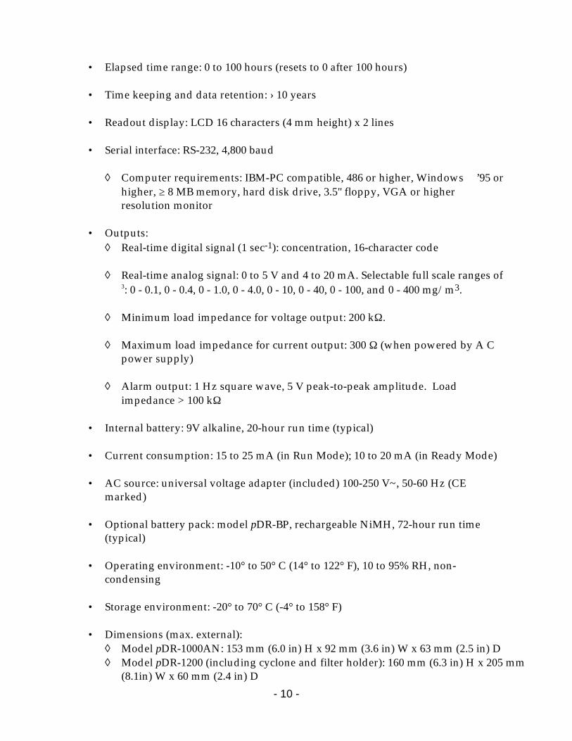
2.0 SPECIFICATIONS • Concentration measurement range (auto-ranging)1: 0.001 to 400 mg/m3 • Scattering coefficient range: 1.5 x 10⁻⁶ to 0.6 m-1 (approx.) @ λ =880 nm • Precision/repeatability over 30 days (2-sigma)2:
± 2% of reading or ±0.005 mg/m3, whichever is larger, for 1-sec. averaging time ±0.5% of reading or ±0.0015 mg/m3, whichever is larger, for 10-sec. averaging time ±0.2% of reading or ±0.0005 mg/m3, whichever is larger, for 60-sec. averaging time
• Accuracy1: ±5% of reading ±precision • Resolution: 0.1% of reading or 0.001 mg/m3, whichever is larger • Particle size range of maximum response: 0.1 to 10 µm • Flow rate range (model pDR-1200 only): 1 to 10 liters/minute (external pump
required) • Aerodynamic particle sizing range (modelpDR-1200 only): 1.0 to 10 µm • Concentration display updating interval: 1 second • Concentration display averaging time3: 1 to 60 seconds • Alarm level adjustment range3: selectable over entire measurement range • Alarm averaging time3: real-time (1 to 60 seconds), or STEL (15 minutes) • Datalogging averaging periods3: 1 second to 4 hours • Total number of data points that can be logged in memory: 13,391 • Number of data tags (data sets): 99 (maximum) • Logged data:
◊ Each data point: average concentration, time/date, and data point number ◊ Run summary: overall average and maximum concentrations, time/date of
maximum, total number of logged points, start time/date, total elapsed time (run duration), STEL concentration and time/date of occurrence, averaging (logging) period, calibration factor, and tag number.
- 10 -
• Elapsed time range: 0 to 100 hours (resets to 0 after 100 hours) • Time keeping and data retention: › 10 years • Readout display: LCD 16 characters (4 mm height) x 2 lines • Serial interface: RS-232, 4,800 baud
◊ Computer requirements: IBM-PC compatible, 486 or higher, Windows ’95 or higher, ≥ 8 MB memory, hard disk drive, 3.5" floppy, VGA or higher resolution monitor
• Outputs:
◊ Real-time digital signal (1 sec-1): concentration, 16-character code ◊ Real-time analog signal: 0 to 5 V and 4 to 20 mA. Selectable full scale ranges of
3: 0 - 0.1, 0 - 0.4, 0 - 1.0, 0 - 4.0, 0 - 10, 0 - 40, 0 - 100, and 0 - 400 mg/m3.
◊ Minimum load impedance for voltage output: 200 kΩ.
◊ Maximum load impedance for current output: 300 Ω (when powered by A C power supply)
◊ Alarm output: 1 Hz square wave, 5 V peak-to-peak amplitude. Load
impedance > 100 kΩ • Internal battery: 9V alkaline, 20-hour run time (typical) • Current consumption: 15 to 25 mA (in Run Mode); 10 to 20 mA (in Ready Mode) • AC source: universal voltage adapter (included) 100-250 V~, 50-60 Hz (CE
marked) • Optional battery pack: model pDR-BP, rechargeable NiMH, 72-hour run time
(typical) • Operating environment: -10° to 50° C (14° to 122° F), 10 to 95% RH, non-
condensing • Storage environment: -20° to 70° C (-4° to 158° F) • Dimensions (max. external):
◊ Model pDR-1000AN: 153 mm (6.0 in) H x 92 mm (3.6 in) W x 63 mm (2.5 in) D ◊ Model pDR-1200 (including cyclone and filter holder): 160 mm (6.3 in) H x 205 mm
(8.1in) W x 60 mm (2.4 in) D
- 11 -
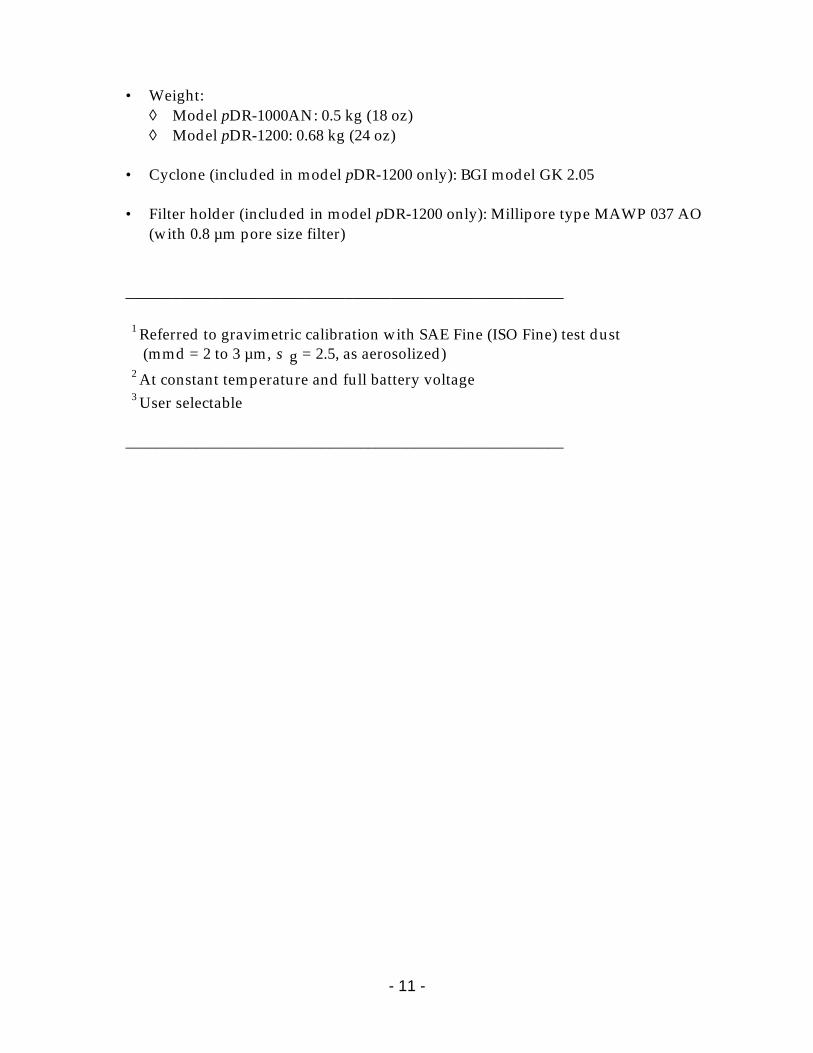
• Weight:
◊ Model pDR-1000AN: 0.5 kg (18 oz) ◊ Model pDR-1200: 0.68 kg (24 oz)
• Cyclone (included in model pDR-1200 only): BGI model GK 2.05 • Filter holder (included in model pDR-1200 only): Millipore type MAWP 037 AO
(with 0.8 µm pore size filter) ________________________________________________________
1 Referred to gravimetric calibration with SAE Fine (ISO Fine) test dust (mmd = 2 to 3 µm, σ g = 2.5, as aerosolized)
2 At constant temperature and full battery voltage 3 User selectable
________________________________________________________
- 12 -
3.0 USER GUIDELINES
3.1 Handling Instructions The personalDataRAM is a sophisticated optical/electronic instrument and should be handled accordingly. Although the personalDataRAM is very rugged, it should not be subjected to excessive shock, vibration, temperature or humidity. As a practical guideline, the personalDataRAM should be handled with the same care as a portable CD player. If the personalDataRAM has been exposed to low temperatures (e.g. in the trunk of a car during winter) for more than a few minutes, care should be taken to allow the instrument to return near room temperature before operating it indoors. This is advisable because water vapor may condense on the interior surfaces of the personalDataRAM causing temporary malfunction or erroneous readings. Once the instrument warms up to near room temperature, such condensation will have evaporated. If the personalDataRAM becomes wet (e.g. due to exposure to water sprays, rain, etc.), allow the unit to dry thoroughly before operating. Whenever the personalDataRAM is shipped care should be taken in placing it in its carrying case and repackaging it with the original cardboard box with the factory provided padding.
3.2 Safety Instructions • Read and understand all instructions in this manual. • Do not attempt to disassemble the instrument. If maintenance is required,
return unit to the factory for qualified service. • The personalDataRAM should be operated only from the type of power
sources described in this manual. • When replacing the internal 9-V battery, follow the instructions provided on
the back panel of the unit. • Shut off personalDataRAM and any external devices (e.g. PC) before
connecting or disconnecting them. • Shut off personalDataRAM before replacing the internal battery, or when
plugging in or disconnecting the AC power supply or the optional rechargeable battery pack.
3.3 Handling and Operation
3.3.1 Model pDR-1000AN
The model pDR-1000AN can be operated in any position or orientation. Exposure to high intensity fluctuating light of the interior of the sensing chamber, through the front and back slotted air openings (see Section 5.5), should be avoided. Such large intensity transients may cause erroneous
- 13 -
readings. Direct access of sunlight to the sensing chamber should be prevented.
Typical modes of instrument support/handling include: • Hand-held. Do not obstruct or cover the sensing chamber opening slots on
front and back of unit. • Belt attached. Use belt clip provided as standard accessory. The unit can be
worn on a waist belt, or with optional shoulder belt (model pDR-SS) for breathing zone monitoring.
• Tabletop operation. The pDR-1000AN can be placed on a table either in an upright position (i.e., resting on its lower protective bumper), or on its back (i.e., resting on the rear edges of its two protective bumpers).
• Tripod mounted. The unit can be attached to any standard tripod using the threaded bushing on the bottom of the monitor (see Figure 3).
• Fixed point operation. The model pDR-1000AN can be mounted at a fixed location (e.g., wall or post) using the optional wall-mounting bracket, model pDR-WB.
3.3.2 Model pDR-1200
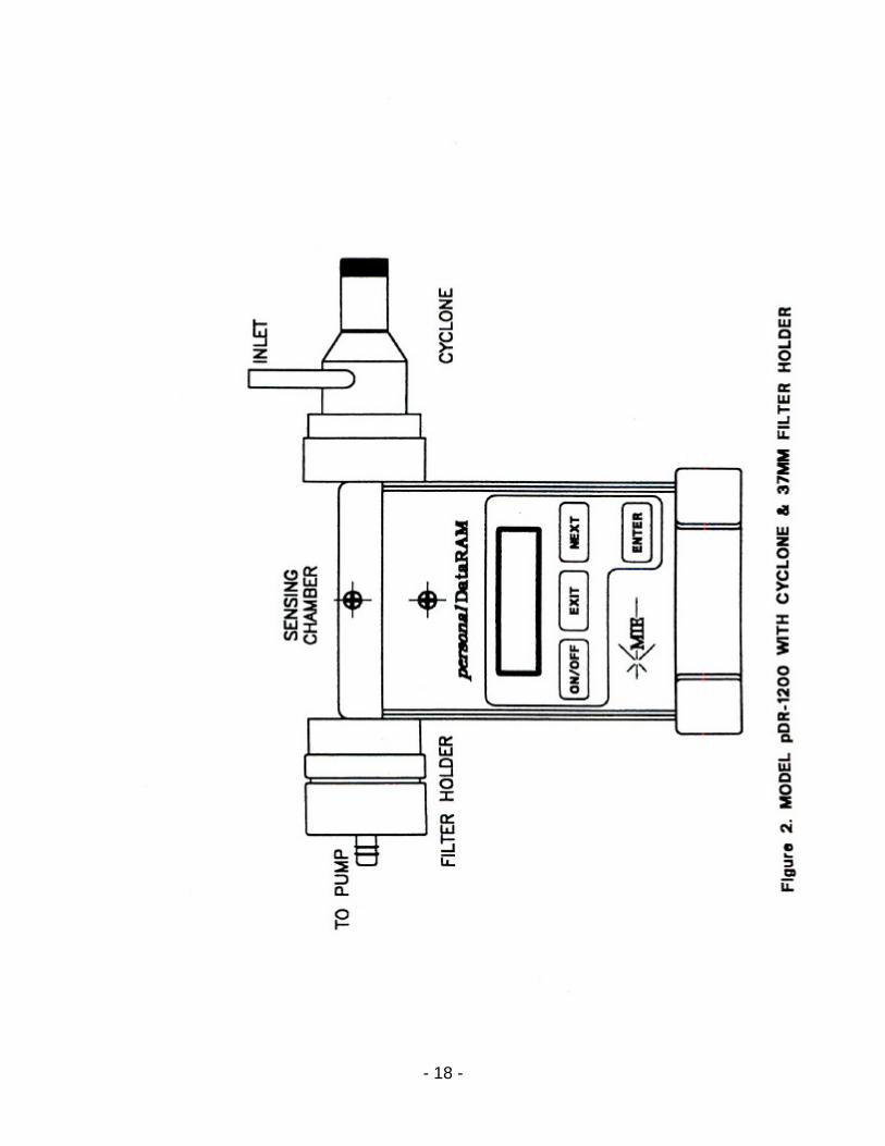
The pDR-1200 requires an external air suction device, such as a small diaphragm pump (e.g., model pDR-PU) for its sampling operation. The inlet of the pump must be connected by means of tubing to the hose fitting on the pDR-1200 filter holder attached to sensing chamber (see Figure 2). The inlet metal tube of the cyclone can be oriented in any desired direction (i.e., upward, forward, downward or backward) by rotating the cyclone body within its holder cup on the right side of the sensing chamber (see Figure 2). Always ensure unobstructed access to the cyclone inlet when sampling directly the air in the instrument's vicinity. Alternatively, tubing can be connected to the cyclone inlet in order to extract a sample stream from a duct, chamber or other enclosed volume.
Typical modes of instrument support/handling include: • Hand-held. For example, using a personal type pump, clipped to the belt and
using a tubing connection to the pDR-1200. • Belt attached. Use belt clip kit provided as standard accessory. The unit can be
worn on a waist belt, or with the optional shoulder belt (model pDR-SS) for breathing zone monitoring. A personal pump can then be belt-worn as well.
• Tabletop operation. The pDR-1200 can be placed on a table either in an upright position (i.e. resting on its lower protective bumper), or on its back (i.e. resting on its backside).
- 14 -
• Tripod mounted. The unit can be attached to any standard tripod using the threaded opening on the bottom base (see accessory attachment fitting on Fig. 4).
• Wall mounted for fixed point monitoring. Use optional wall mounting bracket, model pDR-WB, either in combination with model pDR-PU pump module and model pDR-AC power supply (powering both the pDR-1200 and the pDR-PU), or with a separate pump.
3.4 Air Sampling Guidelines
Although the personalDataRAM is designed primarily for intramural use, i.e. for indoor air quality, in-plant, or mining environment monitoring, its active sampling version (model pDR-1200) also makes it compatible with extramural use (i.e. ambient monitoring). General ambient monitoring applications, however, are performed preferentially using an appropriate inlet configuration, in order to ensure representative particle sampling under conditions of variable wind speed and direction. Consult with MIE for such outdoor applications. For typical area monitoring applications, the personalDataRAM should be placed and operated centrally within the area to be monitored, away from localized air currents due to fans, blowers, ventilation intakes/exhausts, etc. This is to ensure representative sampling within the area to be assessed.
3.5 Environmental Constraints and Certifications The personalDataRAM is designed to be reasonably dust and splash resistant, however, it is not weatherproof. To operate the unit outdoors provisions should be made to protect it from environmental extremes outside its specified range, and from any exposure to precipitation. The personalDataRAM is certified for compliance with the electromagnetic radiation limits for a Class A digital device, pursuant to part 15 of the FCC Rules. The unit also complies and is marked with the CE (European Community) approval for both immunity to electromagnetic radiation and absence of excessive emission interference. 4.0 ACCESSORIES
4.1 Standard Accessories The personalDataRAM is provided to the user with the following standard accessories: • Soft-shell carrying case (MIE model pDR-CC-1) • Digital communications cable (MIE model pDR-DCC) • Analog signal/alarm output cable (MIE model pDR-ANC) • Communications software disk (MIE model pDR-COM)
- 15 -
• Z-Pouch zeroing kit (MIE model pDR-ZP)(for use with pDR-1000AN only) • Zeroing filter cartridge and tubing (MIE model pDR-ZF)(for use with pDR-1200
only) • Belt clip kit (MIE model pDR-CA) • AC power supply (and charger for optional MIE model pDR-BP) (MIE model
pDR-AC) • Metal cyclone (MIE model pDR-GK2.05)(for use with pDR-1200 only) • 37-mm filter holder and hose fitting (MIE model pDR-FH)(for use with pDR-1200
only) • Instruction manual
4.2 Optional Accessories The following optional accessories are available from MIE for use with the personalDataRAM: • Rechargeable battery module (MIE model pDR-BP) • Shoulder strap (MIE model pDR-SS) • Remote alarm unit (MIE model pDR-RA) • Wall mounting bracket (MIE model pDR-WB) • Active sampling kit to convert model pDR-1000AN to model pDR-1200 (MIE
model pDR-ASC) • Upper bumper kit to convert model pDR-1200 to model pDR-1000AN (MIE model
pDR-UB) • Attachable pump unit (MIE model pDR-PU)(for use with pDR-1200 only) 5.0 INSTRUMENT LAYOUT The user should become familiar with the location and function of all externally accessible controls, connectors and other features of the personalDataRAM. Refer to Figures 1 through 6. All user related functions are externally accessible. All repair and maintenance should be performed by qualified MIE personnel. Please contact the factory if any problem should arise. Do not attempt to disassemble the personalDataRAM, except as described in Section 12.0 (Maintenance), otherwise voiding of instrument warranty will result.
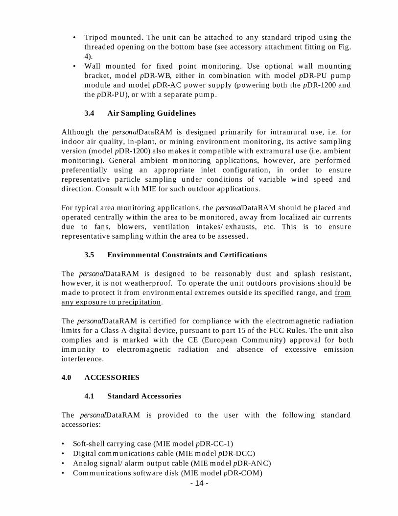
5.1 Front Panel Refer to Figures 1 (for model pDR-1000AN) or 2 (for model pDR-1200) for location of controls and display. The front panel contains the four touch switches (keys) and the LCD screen required for the operation of the personalDataRAM.
- 16 -
The four touch switches provide tactile ("popping") feedback when properly actuated. The ON/OFF key serves only to turn on the unit (while it is in the off state), and to turn it off (when it is operating).

- 17 -
- 18 -
- 19 -
- 20 -
- 21 -
The EXIT and ENTER keys serve to execute specific commands that may be indicated on the screen, and the NEXT key generally serves to scroll the displayed information, e.g. to review the operating parameters that have been programmed, display maximum/STEL values, diagnostic values, etc. If an incorrect command is keyed (e.g. ENTER when the personalDataRAM displays real-time concentration) a beep is heard to alert the user. The two-line, 16-character per line LCD indicates either measured values of concentration (instantaneous and time averaged on the same screen), elapsed run time, maximum and STEL (short term excursion limit) values, operating and logging parameters, diagnostics, or other messages. The acoustic alarm transducer is located directly behind the center of the MIE arrow logo on the front panel.
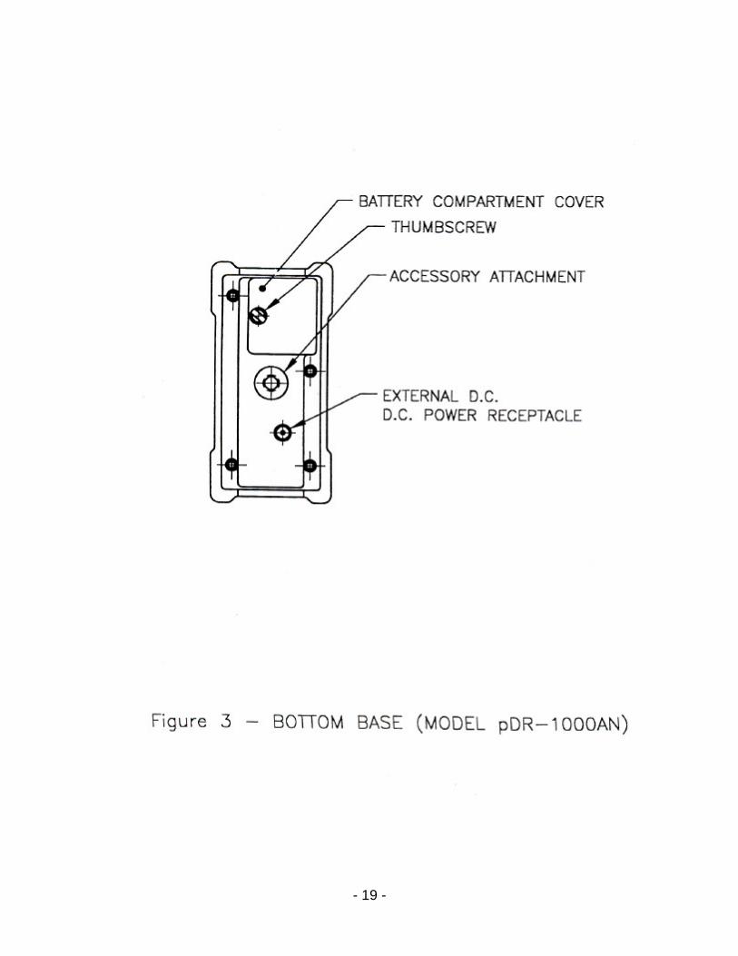
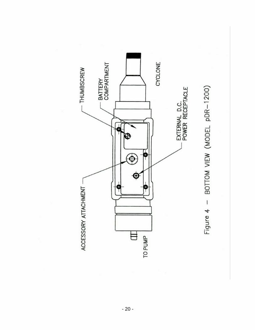
5.2 Bottom Base Refer to Figures 3 (for model pDR-1000AN) or 4 (for model pDR-1200). The base of the personalDataRAM contains the following: a) internal battery compartment cover, b) external DC power input receptacle, and c) threaded bushing for the attachment of optional battery pack, tripod, or other mounting/support hardware. Only the internal battery compartment cover should be opened by the user, for removal and replacement of the on-board 9-V battery. Removal of the base plate could result in voiding of instrument warranty.
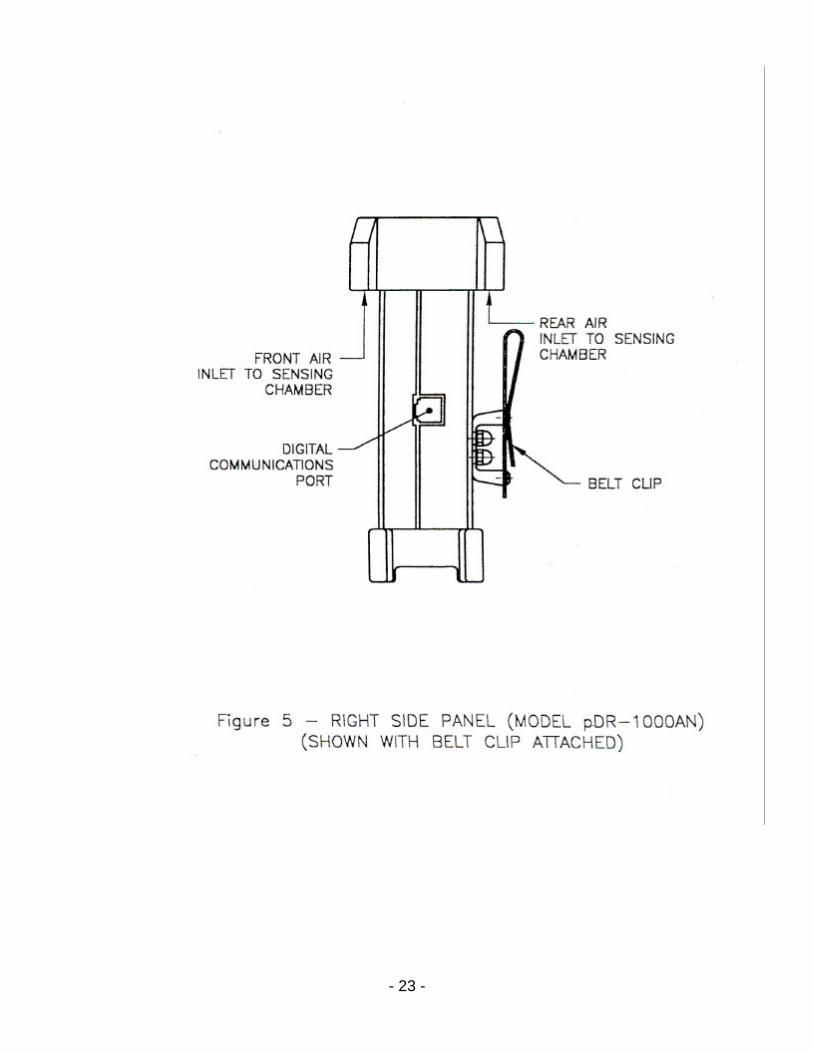
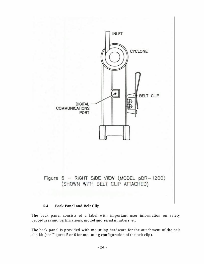
5.3 Right Side Panel Refer to Figures 5 (for model pDR-1000AN) or 6 (for model pDR-1200) which shows the manner of attachment of the belt clip assembly (belt clip should be attached only if required by the user). The right side panel (as viewed from front panel) contains the 6-contact modular jack connector receptacle for digital (RS-232) communications and analog signal output. This connector also provides the alarm output control for a remote/auxiliary alarm signal. The contacts (from top to bottom) are: 1: 4 – 20 mA analog output (positive) 2: Alarm output 3: Digital data transmission 4: Digital input 5: Common ground (signal returns) 6: 0 to 5 V analog output (positive) The digital communications cable provided as a standard accessory is to be inserted into this receptacle for interconnection to a computer (for data downloading or to

- 22 -
reprogram parameters). The analog output cable is provided with flying leads for interconnection with other data processing and/or control systems. WARNING: The modular jack receptacle on the side of the personalDataRAM
should be used only for communications with computers and alarm circuitry. Do not, under any circumstance, connect any communications equipment (e.g., telephone) to this receptacle.
- 23 -
- 24 -
5.4 Back Panel and Belt Clip
The back panel consists of a label with important user information on safety procedures and certifications, model and serial numbers, etc. The back panel is provided with mounting hardware for the attachment of the belt clip kit (see Figures 5 or 6 for mounting configuration of the belt clip).
- 25 -
5.5 Sensing Chamber Referring to Figure 1 or 2, the upper mid-section of the personalDataRAM contains the optical sensing chamber. This chamber is the only internal section that the user should access for maintenance purposes (see Section 12.2). On the model pDR-1000AN, air enters the sensing chamber through the two slot shaped inlets (one on the front and other on the back) under the protective bumper. During instrument operation those two openings should remain unobstructed in order to ensure free access of the surrounding air. When the model pDR-1000AN is used as personal monitor, i.e., clipped to a person’s belt, the rear air inlet opening may be partially obstructed, but care should be exercised in ensuring that the front air inlet remains free of any obstructions. On the model pDR-1200, air enters the sensing chamber through the opening in the cyclone receptacle cup (black cup on right side of sensing chamber), passes through the photometric stage, and exits through the opening in the filter holder receptacle cup (black cup on left side of sensing chamber), after which the air passes through the filter. 6.0 PREPARATION FOR OPERATION
6.1 Battery Installation When shipped from the factory, the personalDataRAM will arrive without its replaceable 9V battery installed. Two fresh alkaline batteries are factory packed separately in the carrying case, one of which should be installed in the personalDataRAM when preparing it for operation. NOTE: Whenever the personalDataRAM is to be left unused for an extended time (i.e. longer than a month), the 9V battery should be removed from the unit. Removing the battery will lose neither the program, time/date keeping, nor stored data.
To install the battery proceed as follows: • Hold the personalDataRAM upside down. • Loosen thumbscrew that secures the battery compartment cover (see Figure 3
or 4), and remove that cover. • Observe battery polarity and the back panel battery orientation pattern (the
negative battery terminal is the one closer to the side of the instrument). • Insert the battery by sliding it in until it bottoms out. It should protrude
slightly above the bottom surface of the instrument. • Place battery compartment cover over battery and, while pushing down the
cover firmly (taking care that the cover seats flush on the bottom surface of the personalDataRAM), tighten thumbscrew securely.
- 26 -
6.2 Battery Replacement
Normally, only alkaline type 9V batteries (type 1604A, or equivalent) should be used with the personalDataRAM. Only fresh batteries should be used in order to ensure the maximum operating time. The personalDataRAM shuts itself off whenever the battery voltage falls below 6 volts (while retaining all programming and data). A fresh 9V alkaline battery, at room temperature, should provide typically 20 hours of continuous operation (please note that not all manufacturers produce batteries of equal capacity). Intermittent operation should extend the total running time because of partial battery recovery effects. The approximate remaining battery capacity is indicated by the personalDataRAM (see Section 8.2) in increments of 1%, starting from 99%. If the remaining battery capacity is 40% or less, immediate restarting after shut off is automatically inhibited to prevent incomplete runs. If, nevertheless, a new run is to be initiated with low remaining battery capacity, do not shut off the personalDataRAM at the end of the previous run (i.e., remain in the Ready Mode, see section 7.0). When significantly extended operating times are required (beyond the typical 20 hours), the use of either lithium or zinc-air batteries can be considered. The use of such alternative battery types can provide about 2 to 3 times longer operation than alkaline batteries.
- 27 -
6.3 AC Power Supply
A universal line voltage AC to DC power supply (MIE model pDR-AC) is provided as standard accessory with the personalDataRAM. This power supply can be used with any line with a voltage between 100 and 240 VAC (50 to 60 Hz). When using that power supply, its output plug should be inserted into the external DC receptacle at the base of the personalDataRAM (see Figure 3 or 4). Insertion of that connector automatically disables the internal 9V battery of the instrument. Removal of the pDR-AC plug from the instrument automatically re-connects the internal 9V battery.
NOTE: Before plugging in or unplugging the external power supply, the personalDataRAM must be shut off.
6.4 Rechargeable Battery Module
A rechargeable battery pack (MIE model pDR-BP) is available as an optional accessory. This unit attaches directly to the base of the personalDataRAM. The pDR-BP contains a sealed nickel-metal-hydride battery, which provides typically 72 hours of continuous operation between successive charges (for 3-hour charging). The use of the personalDataRAM, in combination with the pDR-BP connected to the a.c. power line ensures totally uninterruptible operation over indefinitely long time. In this operating mode, line power interruptions lasting up to 72 hours have no effect on measurement run continuity. To attach the pDR-BP to the personalDataRAM, the instrument should be shut off. Carefully plug the pDR-BP into the external DC RECEPTACLE on the personalDataRAM. Rotate the large thumbscrew at the opposite end of the pDR-BP tightening it firmly. The pDR-BP can be recharged by means of the AC power supply of the personalDataRAM. Detailed instructions for the use of the rechargeable battery module are furnished with that accessory.
6.5 Zeroing the personalDataRAM One of the most important steps to be performed by the user before initiating a measurement run with the personalDataRAM is to zero the instrument. This is required to ensure maximum accuracy of concentration measurements, especially at low levels, i.e. below about 0.1 mg/m3. During the 2-minute pre-run automatic zeroing sequence (see Section 8.1), the personalDataRAM registers its own optical background, stores that level in its memory, and then subtracts that background from all measured concentration values, until the zero is updated again by the user.
- 28 -
Although zeroing can be performed as often as desired (e.g., before every run), in practice it should not be necessary to do so more than once-a-month or even less frequently, except if average particulate concentrations should exceed about 0.5 mg/m3.
6.5.1 Zeroing the model pDR-1000AN Zeroing of the model pDR-1000AN requires a particle-free environment such as a clean room, clean bench, duct or area directly downstream of a HEPA filter, or the pDR-1000AN Z-Pouch (standard accessory). In some cases, a very clean, well air-conditioned office may offer a sufficiently low particle concentration environment (i.e., ≤ 5 µg/m3) for zeroing, as determined by another monitor (e.g., MIE DataRAM). To zero the model pDR-1000AN by means of its Z-Pouch, proceed as follows: • Wipe the outside surfaces of the pDR-1000AN to remove as much dust from those
surfaces as possible before placing the instrument inside the Z-Pouch. • In a reasonably clean environment, open the zipper of the Z-Pouch and place the
pDR-1000AN inside it. Close the zipper shut. • Open the small nipple on the Z-Pouch, and insert the fitting of the hand
pump/in-line filter unit into the nipple. • Start pumping the hand-pump until the Z-Pouch begins to bulge, and proceed
with the steps in Section 8.1, pressing the keys of the instrument through the wall of the Z-Pouch. Then continue pumping.
• After completing the zeroing (step 2. of Section 8.1) procedure, open the Z-Pouch zipper and remove the pDR-1000AN. Close the zipper and flatten the Z-Pouch while plugging its nipple, in order to prevent dust contamination of the interior of the Z-Pouch.
• The pDR-1000AN is now zeroed and ready for a measurement run.
6.5.2 Zeroing the model pDR-1200
To provide the particle-free air required to zero the pDR-1200, either of two methods can be used: a) place the instrument on a clean-air bench or in a clean room, or b) connect to the cyclone inlet the green zeroing filter cartridge supplied with the pDR-1200. In either case, proceed as follows: • After implementing either of the two methods, above, run the attached pump for
at least one minute (e.g., at 4 liters/minute), and then proceed as described in Section 8.1 of this instruction manual, while continuing to run the pump (or leaving the unit in the clean air environment).
• Once the CALIBRATION: OK message appears on the pDR-1200 display, stop the pump and disconnect the zeroing filter cartridge from the cyclone inlet (or remove pDR-1200 from clean bench/room).
• The pDR-1200 is now zeroed and ready for a measurement run.
- 29 -
Note: While the pDR-1200 is used to monitor high dust concentrations (≥ 0.5 mg/m3), the flow through its sensing chamber should not be stopped before purging it, which can be done by connecting the green zeroing filter to the cyclone inlet and continuing to run the pump for about 2 minutes before shutting it off. This is to prevent dust contamination of the sensing chamber.
6.6 pDR-1200 Filter Holder Installation
The 37-mm filter holder provided with the pDR-1200 must be installed before operation of the instrument, in order to connect a sampling pump. To install the filter holder, remove protective cover, and insert the open collar over the black attachment cup with the external o-ring, on the left side of the pDR-1200 sensing chamber. Ensure complete insertion. To replace the membrane filter separate the two sections of the plastic holder prying them apart with screwdriver or a coin. Make sure to place backing under the membrane filter before rejoining the two plastic rings. 7.0 OPERATING MODES The personalDataRAM has several different operating modes which will be described in what follows. The specific commands and displays within each of these operating modes will be explained in detail in Section 8.0. A complete flow chart of keystrokes and screens is provided in Section 16.0.
7.1 Start-Up Mode The personalDataRAM enters the Start-Up Mode as soon as the instrument is switched on. The user then has the choice to:
a) Wait before proceeding; b) Zero the instrument and check its readiness; or c) Proceed directly to the Ready Mode.
7.2 Ready Mode
Once the personalDataRAM is in the Ready Mode, the user is presented with the following alternatives:
a) Start a run immediately, or after any of the subsequent steps; b) Review (by scrolling the display) all operating parameters, status and
diagnostic data; c) Activate or deactivate the logging function; activate, select (instantaneous or
STEL), or deactivate alarm; d) Program parameters or output logged data through a computer.
- 30 -
7.3 Run and Logging Mode The Run Mode is the measurement/logging mode. The user can operate the personalDataRAM in this mode either with or without data logging. For example, the instrument may be used first as a survey monitor without logging, for walk-through assessment of an industrial plant, before deciding where to set up the unit for continuous monitoring and logging.
7.3.1 Data Logging In order to activate the logging function, the unit must be in (or returned to) the Ready Mode (see Section 8.2). If data logging has been enabled, the data will be logged in the next free (unrecorded) tag or data set. For example, if data had been recorded previously in tags # 1, 2 and 3 then, when a new run is initiated, the new data will be stored in tag #4. The data can be separated into number of sets (tags) up to a total of 99. Any number of individual data points can be stored in a given tag, i.e. up to a maximum of 13,000 points (i.e. the total memory capacity of the personalDataRAM) assuming that no other data had been logged in other tags. This means that the total memory capacity of 13,000 data points can be grouped into any number of the available 99 data sets (tags).
7.3.2 Clearing of Memory Data recorded in the personalDataRAM memory can be erased either through an external PC command using the MIE pDR-COM Custom Communications software provided as a standard accessory, or resetting the instrument (see Section 8.5). The PC method permits to erase the data in any number of selected tags, whereas the resetting method results in the deletion of all data stored in the personalDataRAM.
7.3.3 Run Mode Display and Commands When a measurement run has been initiated (see Section 8.3), the user has the following display choices:
a) Instantaneous and time-averaged concentrations (both on the same screen); b) Elapsed run time, and run start time and date (both on the same screen); c) Maximum displayed concentration from run start, and time/date at which
current maximum occurred; d) Short term excursion limit (STEL) from run start, and time/date at which
current STEL occurred; e) Remaining battery charge, and (if logging function is enabled) remaining free
memory. f) Analog output concentration range (if enabled)
The user can command the termination of the run at any time returning it to the Ready Mode. To download logged data into a PC, the personalDataRAM must be in
- 31 -
the Ready Mode. No changes in the program parameters or operating conditions can be made while in the Run Mode. The personalDataRAM can be shut off from any of the three operating modes. Even if shut off while in the Run Mode, the instrument will save all stored data. 8.0 OPERATION
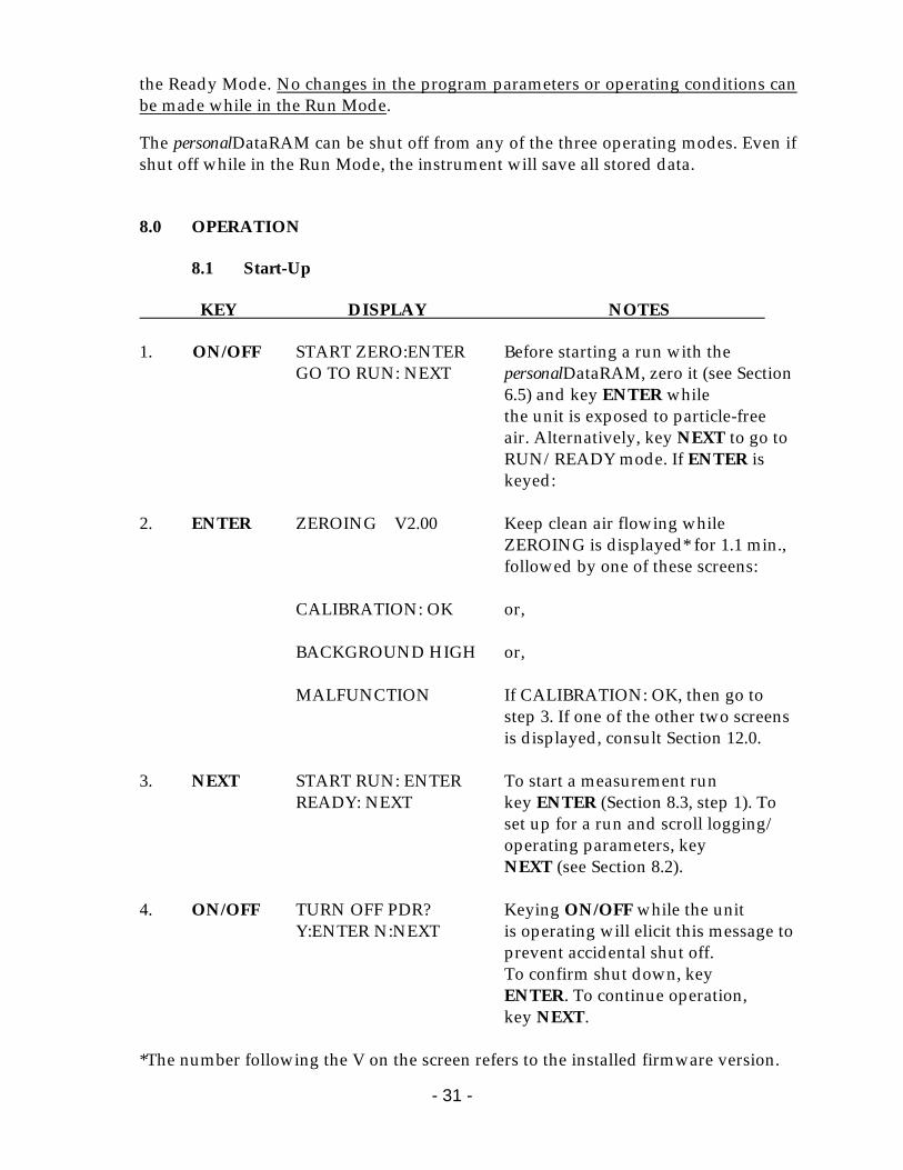
8.1 Start-Up KEY DISPLAY NOTES 1. ON/OFF START ZERO:ENTER Before starting a run with the
GO TO RUN: NEXT personalDataRAM, zero it (see Section 6.5) and key ENTER while
the unit is exposed to particle-free air. Alternatively, key NEXT to go to RUN/READY mode. If ENTER is keyed:
2. ENTER ZEROING V2.00 Keep clean air flowing while ZEROING is displayed* for 1.1 min., followed by one of these screens: CALIBRATION: OK or, BACKGROUND HIGH or, MALFUNCTION If CALIBRATION: OK, then go to step 3. If one of the other two screens is displayed, consult Section 12.0. 3. NEXT START RUN: ENTER To start a measurement run READY: NEXT key ENTER (Section 8.3, step 1). To set up for a run and scroll logging/ operating parameters, key NEXT (see Section 8.2). 4. ON/OFF TURN OFF PDR? Keying ON/OFF while the unit Y:ENTER N:NEXT is operating will elicit this message to prevent accidental shut off. To confirm shut down, key ENTER. To continue operation, key NEXT. *The number following the V on the screen refers to the installed firmware version.
- 32 -
8.2 Setting Up For A Run (Ready Mode)
KEY DISPLAY NOTES__________ 1. NEXT LOGGING DISABLED This screen indicates the logging status. To enable the logging function, key ENTER. Toggling of the on/off logging status can be done by keying ENTER. 2. ENTER LOG INTRVL 600s This message indicates that logging is TAG#: 4 enabled. Example is for 10-min log period, selected through the PC (see Section 9.0), and next free tag is #4. 3. NEXT ALARM: OFF This screen indicates the alarm status. Keying ENTER repeatedly toggles through the 3 alarm modes: 4. ENTER ALARM: INSTANT This enables the alarm based LEVEL:1.50 mg/m3 on the real-time concentration. The level (e.g. 1.50 mg/m3) must be set on the PC. 5. ENTER ALARM: STEL This enables the alarm based LEVEL:0.50 mg/m3 on the 15-min STEL value. The level (e.g. 0.50 mg/m3) must be set on the PC. 6. NEXT ANALOG OUTPUT: This screen indicates the analog signal DISABLED output status. Keying ENTER will enable the analog output. Toggling the analog output on/off can be done by keying ENTER: 7. ENTER ANALOG OUTPUT: This enables the analog output. The 0 – 0.400 mg/m3 concentration range (e.g., 0 – 0.400 mg/m3) must be set on the PC. 8. NEXT CAL FACTOR: 1.00 This screen displays the DIS AVG TIME 10s calibration factor and the display averaging time. Both values can be edited via PC.
- 33 -
9. NEXT BATTERY LEFT 83% This screen displays the
MEMORY LEFT 96% remaining battery charge, and the remaining percentage of free memory.
10. NEXT CONNECT TO PC When this screen has been selected, the operating parameters can be edited and/or the logged data can be downloaded via the PC (see Section 9.0). If NEXT is keyed again, the screen returns to RUN/READY: 11. NEXT START RUN: ENTER The instrument is now READY: NEXT ready to run following the procedure in section 8.3.
8.3 Measurement Run Procedure KEY DISPLAY NOTES___________ 1. ENTER LOGGING DISABLED or, if logging was enabled: LOG INTRVL 600s Logging status will be displayed TAG #: 4 for 3 seconds. CONC*0.047 mg/m3 After a 3-second delay, the concent- TWA 0.039 mg/m3 ration screen appears (values shown here are examples). CONC is the real-time and TWA is the time-averaged concent- ration. The * appears only if logging has been enabled. 2. EXIT TERMINATE RUN? To terminate the current run Y:ENTER N:EXIT and return to the Ready Mode, key ENTER. To continue the run, key EXIT. 3. EXIT CONC*0.047 mg/m3 Keying NEXT successively TWA 0.039 mg/m3 scrolls the display to show various run values (elapsed run time, maximum, STEL, etc.). Keying EXIT from any of those screens returns to the concentration display.
- 34 -
4. NEXT ET 06:12:49 This screen shows the elapsed ST 08:18:26MAY15 run time (ET) and the run start time/date (ST). 5. NEXT MAX: 0.113 mg/m3 This screen shows the maximum T 10:08:44 MAY15 concentration of current run and time/date of occurrence. 6. NEXT STEL:0.058 mg/m3 This screen shows the 15-min T 09:59:22 MAY15 STEL value of the current run and the time/date of occurrence. 7. NEXT BATTERY LEFT 83% or, if logging was enabled: BATTERY LEFT 83% This screen shows the amount MEMORY LEFT 96% of usable charge left in the battery and, if logging has been enabled, the overall amount of free memory left. 8. NEXT ANALOG OUTPUT: This screen shows the status of the 0 – 0.400 mg/m3 analog signal output, and the range, if this output has been enabled. 9. NEXT CONC*0.047 mg/m3 The last NEXT command returns TWA 0.039 mg/m3 the display to the concentration screen. 10. EXIT TERMINATE RUN? As indicated in step 2, to end Y:ENTER N:NEXT current run, key ENTER, to return to the Ready Mode: 11. ENTER START RUN: ENTER This keystroke terminates the READY: NEXT current run and returns the unit to the Ready Mode. If during a run the instrument memory is filled completely, or if all 99 tags have been used, the run is automatically terminated and the display will indicate: RUN TERMINATED FULL MEMORY If a new run is initiated after the memory has been filled, the personalDataRAM can be operated only as a monitor without logging. The memory must then be cleared (see Section 7.3.2) first before logging can be enabled again.
- 35 -
8.4 Abbreviated Run Start/Stop Instructions
To power-up and start a measurement run without zeroing and without logging, proceed as follows: • Key sequentially ON/OFF, NEXT and ENTER. To terminate run and shut down, proceed as follows starting from the concentration screen (otherwise key EXIT first): • Key sequentially EXIT, ENTER, ON/OFF and ENTER.
8.5 Resetting Procedure The personalDataRAM memory can be reset through commands entered on its own keypad (i.e. without requiring a PC). Resetting accomplishes the following: • Erases all stored data from memory; • Resets all parameters and operating conditions to their default values and conditions;
and • Cancels the zero correction offset. WARRING: THE RESET TEST WILL ERASE ALL DATA STORED IN MEMORY
AND SET ALL PARAMETERS TO FACTORY DEFAULT SETTINGS. Download any data before the reset procedure.
The procedure to reset the instrument is as follows: Starting with the unit shut off, press the EXIT and ENTER keys at the same time, and while holding down those two keys, press ON. The screen will then indicate: PDR SELF-TEST... and several diagnostic screens will appear in rapid sequence (see Section 16.0, Resetting/Electronics Checking Mode), ending in the message TESTING COMPLETE. The unit will shut off. When turned on again, the personalDataRAM memory will have been reset, as described above. The default values and operating conditions of the personalDataRAM are: • Logging period (LOG INTRVL): 60 seconds • Logging status: disabled (LOGGING DISABLED) • Alarm level: 1 mg/m3 • Alarm status: disabled (ALARM: OFF) • Analog output: 0 to 4 mg/m3
• Analog output status: disabled (ANALOG OUTPUT :DISABLED) • Real-time display averaging time (DIS AVG TIME): 10 seconds
- 36 -
• Calibration factor (CAL FACTOR): 1.00 When turning on the personalDataRAM after resetting the instrument, it should be zeroed (see steps 1. and 2. of Section 8.1) before a run is initiated. Otherwise, its internal optical background level will not be subtracted from the indicated concentration readings. Alternatively, if the instrument is not zeroed after resetting, it will indicate its unsubtracted optical background when run under particle free conditions. 9.0 COMMUNICATIONS WITH COMPUTER
9.1 Hardware and Software Requirements The computer requirements to install the software provided with the personalDataRAM (MIE pDR-COM) are the following:
• IBM-PC compatible • 486 or better processor • Minimum operating system: Windows 95™ or better • ≥ 8 MB of RAM • 2 MB hard disk drive • 3.5" floppy drive • VGA or higher resolution monitor
NOTE: When large files are logged in the personalDataRAM in one single tag, a
faster computer speed is required to handle the data. For example, if all 13,000 data points are logged in one tag, a Pentium I or II processor with a minimum speed of 166 MHz will be required. If, however, the maximum number of data points per tag is 1,000 or below, a 33 MHz, 486 DX processor will suffice.
MIE custom hardware and software (provided as standard accessories):
• Digital communications cable (MIE model pDR-DCC) • Software floppy disk (3.5", MIE model pDR-COM)
9.2 Software Installation Procedure
To install the MIE provided software in the computer, proceed as follows:
1. Insert the 3.5" disk labeled "pDR-COM" into computer. 2. For Windows 95™ users, select Start and then Run. For Windows 3.1 and 3.11
users, from Program Manager select File and then Run. 3. Type in on the Command Line: a: install (or b: install, as required). 4. The message "Do you wish to install pDR-COM?" will appear. Click OK to
continue, or Cancel. 5. A message appears allowing the option to change the default directory:

- 37 -
"C:\PDRCOM". It is advisable to leave the default directory (unless you address the hard drive by a different letter), and select OK.
6. After a successful installation, the message "Installation Complete!" will appear.
- 38 -
9.3 Communication Between personalDataRAM and Computer To effect the communication between the personalDataRAM (via the pDR-COM software installed in the computer as described in the preceding section) and the PC, proceed as follows:
1. Connect the personalDataRAM to one of the computer's serial ports using the pDR-DCC cable provided by MIE. This cable has a 9-pin female connector for the computer port.
2. Key ON the personalDataRAM and then key NEXT repeatedly until
CONNECT TO PC is displayed on the personalDataRAM. 3. On the computer, double click on the pDR-COM icon. A four-tabbed
notebook display should appear. Click on the Com Port Select and select the port to which the pDR-DCC cable has been connected.
4. From the four-tabbed notebook displayed on the computer screen select the
tab with the desired option. The options are:
• Main: This page allows the user to input the personalDataRAM serial number (or any other desired label), and select the Serial Com Port.
• Logged data: This page allows the user to download, tabulate, print data, or
transfer to a CSV file the data stored in the personalDataRAM. This page also serves to display real-time numerical data when the computer is connected to the personalDataRAM in the Run Mode.
• Graph data: This page enables the downloading and graphing of stored data
to the computer screen and to a printer. In the Run Mode, this page displays the real-time data in graphic format.
• Configure pDR: This screen allows the user to edit the operating/logging
parameters. Click on the item to be edited and select or type in the new value. To review the parameter values currently programmed into the personalDataRAM, click on Get configuration. After editing the parameters, click on Set configuration to input the new values into the personalDataRAM program.
Most operations within pDR-COM are self-evidently labeled, including fly-over dialog boxes. In addition, instructions may be found in the On-line Help files by selecting Help and then Contents. The following operating/logging parameters of the personalDataRAM are selected (edited) via the computer:
• Current date (month and day of the month)
- 39 -
• Current time (hour, minute and second) • Display averaging time (1 to 60 seconds, in 1-second increments) • Calibration factor (0.01 to 9.99, in 0.01 increments) • Logging interval (1 to 14,400 seconds, in 1-second increments) • Analog output full scale concentration (0.1, 0.4, 1, 4, 10, 40, 100, or 400 mg/m3) • Analog output status (enabled, or disabled) (can also be selected directly
through personalDataRAM keyboard, see Section 8.2) • Alarm level (0.001 to 409.599 mg/m3, in 1-µg/m3 increments) • Alarm mode (Off, Instantaneous, or STEL) (can also be selected directly
through personalDataRAM keyboard, see Section 8.2) The serial number of the personalDataRAM is transferred automatically to the PC and displayed on its screen. In addition, the user can input any other identification for the instrument (up to 20 characters).
Note: The year is entered as a two-digit number; year 2000 is treated correctly as a leap year (personalDataRAM version 1.70 or higher).
9.4 Real-Time RS-232 Output
During the RUN mode, the personalDataRAM can communicate real-time concentration data through its serial port via the pDR-COM software package. This software application decodes the data and displays it on the computer screen in both graphical and tabulated form. In order to use this output with some other application, the following information will enable the user to decipher the encoded output signal. The communication settings for the digital output of the personalDataRAM are:
• Baud rate: 4800 bps or 9600 bps • Data bits: 8 • Stop bits: 1 • Parity: none • Flow control: Xon/Xoff
Every second during a run, the personalDataRAM serial port will output a sixteen-character code. It consists of two brackets with 14 hexadecimal digits between them, representing sum check (2 digits), sensed concentration (8 digits), and calibration factor (%, 4 digits). The concentration in µg/m3 is obtained by multiplying the sensed concentration times the calibration factor and dividing by 100.
- 40 -
10.0 ANALOG SIGNAL OUTPUT
10.1 Analog Output Description The personalDataRAM incorporates the capability to provide both a voltage and a current signal output directly proportional to the sensed concentration of airborne particulates. Both these analog signal outputs are concurrently available. These outputs are provided, principally, for fixed-point applications with hard-wired installations, such as for continuous HVAC monitoring and control. The particulate concentration range corresponding to the output voltage and current ranges (0 to 5 V and 4 to 20 mA) can be user selected (via a PC). The most sensitive range available is 0 to 0.100 mg/m3, and the least sensitive range is 0 to 400 mg/m3. For example, if the user selects the analog output range of 0 to 0.400 mg/m3 then the analog output signal levels, at a concentration of 0.200 mg/m3, would be 2.5 V and 12 mA. Selection of the concentration range of the analog output must be performed on the PC. This range is independent of the digital display, data logging and real-time digital output range which are controlled automatically (auto-ranging). Enabling the analog output increases the current consumption from the power source (battery or power supply) of the personalDataRAM by typically 5 mA when no load is connected to the analog signal current output. If such a load is connected then the current consumption of the personalDataRAM further increases by the magnitude of the output signal current (up to a maximum increment of 20 mA). Therefore, when not using the analog output, it is advisable to disable that output (see Section 8.2) in order to minimize power consumption (this is important only when powering the personalDataRAM from a battery source). 10.2 Analog Output Connection The personalDataRAM is provided with a cable (model pDR-ANC) which has a 6-contact plug at one end and flying leads at the other. There are 4 leads for the analog and alarm outputs. The additional two contacts of the connector are used only for digital communication with a PC, for which a separate cable (model pDR-DCC) is provided. Counting from top to bottom on the personalDataRAM connector receptacle, contact #1 is the positive 4 – 20 mA analog output, contact #2 is the alarm output, contact #5 is the common ground (return for all signals), and contact #6 is the positive 0 – 5 V analog output. For the 0 – 5 V output signal, the externally connected load must have an impedance of more than 200 kilo-ohms. For the 4 – 20 mA output signal, the externally connected load must have an impedance of less than 200 ohms when powering the
- 41 -
personalDataRAM with a battery, or less than 300 ohms when using the its AC supply. Since both voltage and current outputs are present at the same time, both can be used concurrently, if so required. The accuracy of the analog output signals is better than 1% of the reading with respect to the digital reading. 11.0 ALARM
11.1 Alarm Description and Operation The personalDataRAM alarm function is provided both as an audible signal as well as an electrical output. The audible alarm consists of a series of beeps generated by an on-board piezo-transducer. The electrical output, available at the digital communications port, consists of a 1 Hz square wave signal which can be used to trigger/activate other equipment through an appropriate interface (consult with the factory). The alarm function can be enabled/disabled by the user through the personalDataRAM keyboard (see Section 8.2). Setting of the alarm level must be performed on the PC (see Section 9.0). The alarm is triggered whenever the preset alarm level is exceeded based either on : a) the displayed real-time concentration, if ALARM: INSTANT was selected (see Section 8.2), or b) a 15-minute running average concentration, if ALARM: STEL was selected. When the concentration falls below that level the alarm condition stops. While the alarm is on the user can stop it (i.e. silence the alarm) by pressing any key of the personalDataRAM. If the concentration continues to exceed the set alarm level after 10 seconds, however, the alarm restarts.
11.2 Alarm Output A pulsed voltage output is available on the personalDataRAM in synchronism with the audible signal. This signal consists of a 1 Hz square wave with an amplitude level of 5 V pp. An externally connected load should have an impedance of no less than 100 kilo-ohms. This alarm output signal is available at pins 2 and 5 (counting from top to bottom) of the 6-contact output/communications port on the side of the personalDataRAM (see Figure 5 or 6).
11.3 Remote Alarm Unit An alarm relay unit (MIE model pDR-RA) is available as an optional accessory for the personalDataRAM. The pDR-RA, when connected to the alarm output of the personalDataRAM, provides a switched output triggered by the alarm signal of the monitor. This switched output (up to 8 amperes, 250 volts) can be used to activate or
- 42 -
deactivate other equipment (e.g. ventilation systems, machinery, etc.), or to control remotely located (by wire connection) alarm indicators (e.g. buzzers, lights, etc.). 12.0 MAINTENANCE
12.1 General Guidelines The personalDataRAM is designed to be repaired at the factory. Access to the internal components of the unit by others than authorized personnel voids warranty. The exception to this rule is the occasional cleaning of the optical sensing chamber. Unless a MALFUNCTION message is displayed, or other operational problems occur, the personalDataRAM should be returned to the factory once every two years for routine check out, test, cleaning and calibration check.
12.2 Cleaning of Optical Sensing Chamber Continued sampling of airborne particles may result in gradual build-up of contamination on the interior surfaces of the sensing chamber components. This may cause an excessive rate of increase in the optical background. If this background level becomes excessive, the personalDataRAM will alert the user at the completion of the zeroing sequence, as indicated in Section 8.1, by the display of a BACKGROUND HIGH message. If this message is presented, the personalDataRAM can continue to be operated providing accurate measurements. However, it is then advisable to clean the interior of the sensing chamber at the first convenient opportunity, proceeding as indicated below.
12.2.1 Model pDR-1000AN • Remove the two screws on the top of the large protective bumper that covers the
sensing chamber (see Figure 1); • Remove the large protective bumper by lifting it firmly upwards and away from
the sensing chamber; • Remove the socket-head screws on the front and back black covers that were
exposed by removal of the large top bumper. Lift away the freed front and back covers of the sensing chamber; set them aside carefully and such that they can be reattached in the same position as they were previously; avoid touching the dull black side of these plates;
• Using filtered (particle-free) pressurized air, blow the inside of the sensing chamber taking great care in not marring or scratching any of the exposed surfaces;
• Reposition the two sensing chamber cover plates in the same location (front and back) as they had been originally. Insert and tighten socket head screws firmly making sure that the two plates are aligned perfectly with the top of the sensing chamber;
- 43 -
• Reposition large protective bumper over sensing chamber pushing down until properly seated. Insert the two top screws holding down the bumper and tighten gently (do not over-tighten);
• Check optical background by zeroing the pDR-1000AN as indicated in Section 8.1. If the sensing chamber cleaning was performed correctly, the message CALIBRATION: OK should be displayed at the end of the zeroing period.
12.2.2 Model pDR-1200
• Remove the two screws (one in the front and one in the back) holding the front
and back gasketed covering plates of the sensing chamber, and set these plates aside, such that they may be reattached in the same location as they were previously.
• Using filtered (particle-free) pressurized air, blow the inside of sensing chamber taking great care in not marring or scratching any of the exposed surfaces.
• Reposition the two sensing chamber cover plates in the same location (front and back) as they had been originally. Insert and tighten socket head screws firmly making sure that the two plates are aligned perfectly with the top of the sensing chamber.
• Check optical background by zeroing the pDR-1200 as indicated in Section 8.1. If the sensing chamber cleaning was performed correctly, the message CALIBRATION: OK should be displayed at the end of the zeroing period.
12.3 Cyclone Cleaning (Model pDR-1200 only)
The cyclone will require occasional cleaning. It is advisable to do so whenever the sensing chamber of the pDR-1200 is cleaned (see above). To clean the cyclone, remove it from its black attachment cup on the sensing chamber, and unscrew the grit pot (narrower knurled end). Use clean pressurized air to blow out the grit pot and through all openings of cyclone body. Reattach grit pot to cyclone body and insert cyclone body into attachment cup making sure it is fully inserted. 13.0 CALIBRATION
13.1 Factory Calibration Each personalDataRAM is factory calibrated against a set of reference monitors that, in turn, are periodically calibrated against a gravimetric standard traceable to the National Institute of Standards and Testing (NIST). The primary factory reference method consists of generating a dust aerosol by means of a fluidized bed generator, and injecting continuously the dust into a mixing chamber from which samples are extracted concurrently by two reference filter collectors and by two master real-time monitors (MIE DataRAMs) that are used for the routine calibration of every personalDataRAM.
- 44 -
The primary dust concentration reference value is obtained from the weight increase of the two filters due to the dust collected over a measured period of time, at a constant and known flow rate. The two master real-time monitors are then adjusted to agree with the reference mass concentration value (obtained from averaging the measurements of the two gravimetric filters) to within ±1%. Three primary, NIST traceable, measurements are involved in the determination of the reference mass concentration: the weight increment from the dust collected on the filter, the sampling flowrate, and the sampling time. Additional conditions that must be met are: a) suspended dust concentration uniformity at all sampling inlets of the mixing chamber; b) identical sample transport configurations leading to reference and instrument under calibration; and c) essentially 100% collection efficiency of filters used for gravimetric reference for the particle size range of the test dust. The test dust used for the MIE factory calibration of the personalDataRAM is SAE Fine (ISO Fine) supplied by Powder Technology, Inc. It has the following physical characteristics (as dispersed into the mixing chamber):
• Mass median aerodynamic particle diameter: 2 to 3 µm • Geometric standard deviation of lognormal size distribution: 2.5 • Bulk density: 2.60 to 2.65 g/cm3 • Refractive index: 1.54
13.2 Field Gravimetric Calibration
If desired, the personalDataRAM can be calibrated gravimetrically for a particular aerosol (dust, smoke, mist, etc.) under field conditions (actual conditions of use). To effect such calibration in the particle environment of interest, proceed as indicated below. For field calibration of the model pDR-1000AN, a personal type filter sampler is placed side-by-side (collocated) to the pDR-1000AN to be calibrated, and the two units should be started simultaneously. For the model pDR-1200, its own filter and attached pump can be conveniently used for the same purpose.
• Weigh and load into filter holder a fresh membrane filter. • Start pump. • Immediately turn on personalDataRAM and start a run such that the pump
and the personalDataRAM are started nearly simultaneously. The duration of this comparison run should be sufficient to collect a mass of at least 1 mg on the reference filter (in order to permit accurate weighing of the collected mass by means of an analytical balance). The time-weighted average (TWA) reading of the personalDataRAM can be used to estimate the required sampling time to collect the above-mentioned mass on the filter. To estimate the required sampling time (ET as measured on the personalDataRAM) in minutes, read the TWA value (see Section 8.3)
- 45 -
after an elapsed time (ET) of one minute or more, and apply the following relationship:
ET ≥ 500/TWA For example, if TWA = 2.5 mg/m3, then ET ≥ 200 minutes (approximately 3 hours). If the TWA value changes significantly as the run proceeds, recalculate the required ET accordingly. At the end of the run (after time ET has elapsed), record TWA, ET and the flow rate Q used to sample the air. Weigh the filter on an analytical balance and obtain ∆m, the mass increment due to the collected particles. Calculate the average gravimetric concentration C, as follows:
C = 1000 ∆m/ETxQ Compare the recorded value of TWA and the calculated value C, and calculate the calibration factor to be programmed into the personalDataRAM (see Section 9.0) as follows:
CAL FACTOR = C/TWA For example, if C was found to be 3.2 mg/m3, and TWA had been determined to be 2.5 mg/m3, the CAL FACTOR equals 1.28. Select this value on the PC, as described in Section 9.0. This completes the gravimetric calibration of the personalDataRAM for a specific aerosol.
13.3 Scattering Coefficient Calibration Users interested in using the personalDataRAM for scattering coefficient measurements (e.g., for atmospheric visibility monitoring) should contact the factory. A special primary Rayleigh scattering calibration for such purpose can be performed by the factory.
13.4 Internal Span Check The zeroing procedure (see Section 8.1) and the resulting normal diagnostic display of "CALIBRATION: OK" (step 2) informs the user that the instrument's calibration agrees with the original factory setting. This is an internal span check that consists of an automatic comparison between the initial (factory) optical background of the personalDataRAM (registered in its non-volatile memory), and the current optical background sensed during the zeroing sequence. 14.0 PARTICLE SIZE CLASSIFICATION (model pDR-1200 only)
- 46 -
The particle size selective cyclone of the pDR-1200 provides the user with two important capabilities: a) to measure the particulate matter concentration of a specific aerodynamic size fraction, and b) to determine the mass median size of a particle population. These two applications will be discussed in what follows. For both these applications, a variable measured flow rate pump is required, such as the model pDR-PU (for which a separate instruction manual is provided).
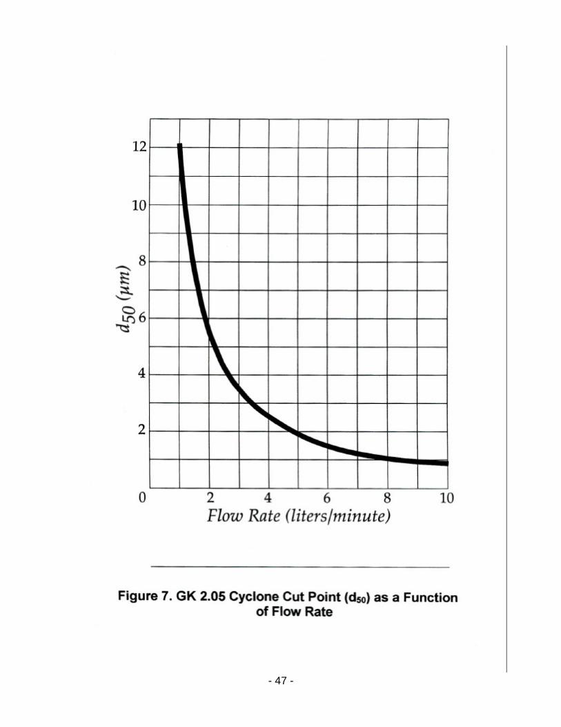
14.1 Size Fractionated Monitoring The pDR-1200 can be used to monitor a specific particle size fraction below a selectable cut off equivalent aerodynamic diameter. The particle size cut point can be selected by adjustment of the sampling flow rate. The higher this flow rate through the cyclone the smaller the cut off particle diameter. Figure 7 is a graph showing the dependence of the particle cut off size in micrometers as a function of the sampling flow rate in liters per minute. The cut off size is the particle aerodynamic diameter at which the collection efficiency of the cyclone is 50%, or conversely, the size at which the cyclone transmission is 50%. For example, to obtain a particle size cut off of 2.5 µm (i.e., PM2.5), the required sampling flow rate is 4 liters/minute. A that flow rate only particles smaller than (approximately) 2.5 µm are allowed to pass into the pDR-1200 sensing stage, to be monitored and then to be collected on the filter. As can be seen on Fig. 7, the lowest particle size cut for the GK 2.05 cyclone included with the pDR-1200 is about 1 µm, and the largest is about 12 µm. For particle size classification outside this range, consult with the factory.
14.2 Particle Sizing The selectable particle size capability of the cyclone, in combination with the concentration measuring capability of the photometric system of the pDR-1200 permits the user to determine the mass median aerodynamic particle diameter of an aerosol, i.e., of the airborne particle population being sampled. One simple procedure to determine the median particle size is as follows (please refer to the graph of Fig. 7):
• Remove cyclone from its black attachment cup and set cyclone aside • Start pump and sample aerosol at a flow rate between 2 and 4 liters/minute • Press ON key on pDR-1200 panel and after about one minute key NEXT and
then ENTER • After an elapsed time (ET) of about one minute, read and note TWA
concentration •Shut off pump
- 47 -
- 48 -
• Plug in cyclone into its attachment cup • Start pump and run at about 1 liter/minute. Observe real-time concentration
(CONC) reading • Increase flow rate very slowly and gradually until CONC reading is one-half
of the initial concentration measured without the cyclone. Continue sampling at this flow rate for about one minute and confirm that TWA reading is about one-half of the initial one. Otherwise readjust flow rate. Note final flow rate at which the TWA value has decreased to one-half the value noted without the cyclone.
• Enter the final flow rate for which the TWA value is one-half of the initial
value into the graph of Fig. 7 and read the corresponding d50 particle size in micrometers. This represents the mass median particle diameter of the aerosol.
For example, if the TWA value without the cyclone was 0.8 mg/m3, and the flow rate (with the cyclone attached) required to reduce the TWA to 0.4 mg/m3 is 2 liters/minute, the mass median particle size (as obtained from the curve of Fig. 7) is approximately 5.5 µm.
15.0 CONVERSION BETWEEN personalDataRAM VERSIONS The personalDataRAM user has the option to convert from a model pDR-1000AN to a modelpDR-1200 or vice versa using the appropriate conversion kit. To convert from a pDR-1000AN to a pDR-1200 (i.e., from a passive air sampling configuration to an active one), the user requires the model pDR-ASC conversion kit. To convert from a pDR-1200 to a pDR-1000AN (i.e., from an active air sampling configuration to a passive one), the user requires the model pDR-UB conversion kit.
15.1 Conversion Procedure From pDR-1000AN to pDR-1200
To effect this conversion, use model pDR-ASC conversion kit. As you remove parts from the pDR-1000AN, in order to attach the conversion kit components, store these parts carefully for possible future re-conversion. Proceed as follows: • Remove the two screws on the top of the large protective bumper that covers
the sensing chamber (see Figure 1). This bumper is not used on the pDR-1200; • Remove the large protective bumper by lifting it firmly upwards and away
from the sensing chamber; • Reinsert in the upper two threaded holes and tighten the two screws that had
held the protective bumper; • Remove the socket-head screws on the front and back black covers that were
exposed by removal of the large top bumper. Lift away the freed front and back covers of the sensing chamber; store them carefully for future use, ensuring that their surfaces are not scratched or marred;
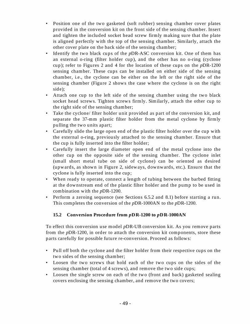
- 49 -
• Position one of the two gasketed (soft rubber) sensing chamber cover plates provided in the conversion kit on the front side of the sensing chamber. Insert and tighten the included socket head screw firmly making sure that the plate is aligned perfectly with the top of the sensing chamber. Similarly, attach the other cover plate on the back side of the sensing chamber;
• Identify the two black cups of the pDR-ASC conversion kit. One of them has an external o-ring (filter holder cup), and the other has no o-ring (cyclone cup); refer to Figures 2 and 4 for the location of these cups on the pDR-1200 sensing chamber. These cups can be installed on either side of the sensing chamber, i.e., the cyclone can be either on the left or the right side of the sensing chamber (Figure 2 shows the case where the cyclone is on the right side);
• Attach one cup to the left side of the sensing chamber using the two black socket head screws. Tighten screws firmly. Similarly, attach the other cup to the right side of the sensing chamber;
• Take the cyclone/filter holder unit provided as part of the conversion kit, and separate the 37-mm plastic filter holder from the metal cyclone by firmly pulling the two units apart;
• Carefully slide the large open end of the plastic filter holder over the cup with the external o-ring, previously attached to the sensing chamber. Ensure that the cup is fully inserted into the filter holder;
• Carefully insert the large diameter open end of the metal cyclone into the other cup on the opposite side of the sensing chamber. The cyclone inlet (small short metal tube on side of cyclone) can be oriented as desired (upwards, as shown in Figure 2, sideways, downwards, etc.). Ensure that the cyclone is fully inserted into the cup;
• When ready to operate, connect a length of tubing between the barbed fitting at the downstream end of the plastic filter holder and the pump to be used in combination with the pDR-1200.
• Perform a zeroing sequence (see Sections 6.5.2 and 8.1) before starting a run. This completes the conversion of the pDR-1000AN to the pDR-1200.
15.2 Conversion Procedure from pDR-1200 to pDR-1000AN
To effect this conversion use model pDR-UB conversion kit. As you remove parts from the pDR-1200, in order to attach the conversion kit components, store these parts carefully for possible future re-conversion. Proceed as follows: • Pull off both the cyclone and the filter holder from their respective cups on the
two sides of the sensing chamber; • Loosen the two screws that hold each of the two cups on the sides of the
sensing chamber (total of 4 screws), and remove the two side cups; • Loosen the single screw on each of the two (front and back) gasketed sealing
covers enclosing the sensing chamber, and remove the two covers;
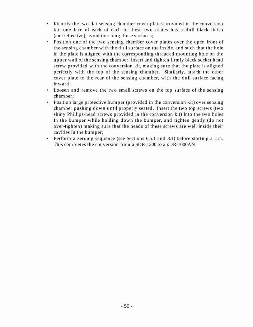
- 50 -
• Identify the two flat sensing chamber cover plates provided in the conversion kit; one face of each of each of these two plates has a dull black finish (antireflective); avoid touching those surfaces;
• Position one of the two sensing chamber cover plates over the open front of the sensing chamber with the dull surface on the inside, and such that the hole in the plate is aligned with the corresponding threaded mounting hole on the upper wall of the sensing chamber. Insert and tighten firmly black socket head screw provided with the conversion kit, making sure that the plate is aligned perfectly with the top of the sensing chamber. Similarly, attach the other cover plate to the rear of the sensing chamber, with the dull surface facing inward;
• Loosen and remove the two small screws on the top surface of the sensing chamber;
• Position large protective bumper (provided in the conversion kit) over sensing chamber pushing down until properly seated. Insert the two top screws (two shiny Phillips-head screws provided in the conversion kit) Into the two holes In the bumper while holding down the bumper, and tighten gently (do not over-tighten) making sure that the heads of these screws are well Inside their cavities In the bumper;
• Perform a zeroing sequence (see Sections 6.5.1 and 8.1) before starting a run. This completes the conversion from a pDR-1200 to a pDR-1000AN.
- 51 -
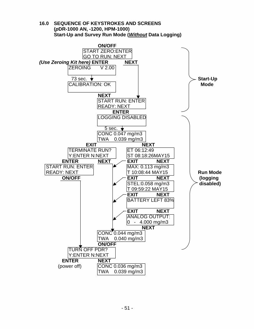
16.0 SEQUENCE OF KEYSTROKES AND SCREENS (pDR-1000 AN, -1200, HPM-1000) Start-Up and Survey Run Mode (Without Data Logging)
ON/OFF START ZERO:ENTER GO TO RUN: NEXT (Use Zeroing Kit here) ENTER NEXT ZEROING V 2.00 73 sec. Start-Up CALIBRATION: OK Mode NEXT START RUN: ENTER READY: NEXT ENTER LOGGING DISABLED 5 sec. CONC 0.047 mg/m3 TWA 0.039 mg/m3 EXIT NEXT TERMINATE RUN? ET 06:12:49 Y:ENTER N:NEXT ST 08:18:26MAY15 ENTER NEXT EXIT NEXT START RUN: ENTER MAX: 0.113 mg/m3 READY: NEXT T 10:08:44 MAY15 Run Mode ON/OFF EXIT NEXT (logging
STEL:0.058 mg/m3 disabled) T 09:59:22 MAY15 EXIT NEXT BATTERY LEFT 83% EXIT NEXT ANALOG OUTPUT: 0 - 4.000 mg/m3 NEXT CONC 0.044 mg/m3 TWA 0.040 mg/m3 ON/OFF TURN OFF PDR? Y:ENTER N:NEXT ENTER NEXT
(power off) CONC 0.036 mg/m3 TWA 0.039 mg/m3
- 52 -
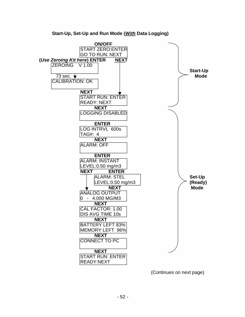
Start-Up, Set-Up and Run Mode (With Data Logging)
ON/OFF START ZERO:ENTER GO TO RUN: NEXT (Use Zeroing Kit here) ENTER NEXT ZEROING V 1.00 Start-Up 73 sec. Mode CALIBRATION: OK NEXT START RUN: ENTER READY: NEXT NEXT LOGGING DISABLED ENTER LOG INTRVL 600s TAG#: 4 NEXT ALARM: OFF ENTER ALARM: INSTANT LEVEL:0.50 mg/m3 NEXT ENTER ALARM: STEL Set-Up LEVEL:0.50 mg/m3 (Ready) NEXT Mode ANALOG OUTPUT 0 - 4.000 MG/M3 NEXT CAL FACTOR: 1.00 DIS AVG TIME 10s NEXT BATTERY LEFT 83% MEMORY LEFT 96% NEXT CONNECT TO PC NEXT START RUN: ENTER READY:NEXT
(Continues on next page)
- 53 -
ENTER LOG INTRVL 600s TAG#: 4 5 sec. CONC*0.047 mg/m3 TWA 0.039 mg/m3 CONC*0.054 mg/m3 TWA 0.041 mg/m3 EXIT NEXT TERMINATE RUN? ET 06:12:49 Y:ENTER N:NEXT ST 08:18:26MAY15 ENTER NEXT EXIT NEXT Run Mode START RUN: ENTER MAX: 0.113 mg/m3 (logging READY: NEXT T 10:08:44 MAY15 enabled) ON/OFF EXIT NEXT STEL:0.058 mg/m3 T 09:59:22 MAY15 EXIT NEXT BATTERY LEFT 83% MEMORY LEFT 96% EXIT NEXT ANALOG OUTPUT: 0 - 4.000 mg/m3 NEXT CONC*0.044 mg/m3 TWA 0.040 mg/m3 ON/OFF TURN OFF PDR? Y:ENTER N:NEXT ENTER NEXT (power off) CONC*0.036 mg/m3 TWA 0.039 mg/m3
- 54 -
Resetting/Electronic Checking Mode EXIT + ENTER + ON/OFF PDR SELF-TEST… TESTING ALARM PDR SELF-TEST… TESTING SERIAL PDR SELF-TEST… TESTING CLOCK PDR SELF-TEST… Automatic TESTING A/D Sequence (30 – 40 sec.) PDR SELF-TEST… TESTING D/A PDR SELF-TEST… TESTING MEMORY PDR SELF-TEST… TESTING COMPLETE (automatic power off)
NOTE: After the preceding resetting sequence, the instrument should be zeroed; otherwise its optical background will remain unsubtracted.
When the Error Message “Malfunction” displays In the event that the PDR series instrument displays the error message “Malfunction” here are two steps that should be taken by the owner/ operator. With unit attached to the computer, proceed as follows: Check the minimum background of the unit. To do this you need to utilize pDR-COM software (PDRCOM.EXE) loaded into your computer. Click on `Configure pDR’. Click on `Get Configuration’. Press both the “ALT” key and the letter “B” key of the computer keyboard and the following message will be displayed:
Waring! Consult the manufacturer before editing MinBG, MaxBG or the Serial Number. Click on the `OK’ box and you should see S/N, MinBG, MaxBG boxes. Set the MinBG to 100 and click on `Set Configuration’. Click on `OK’ then exit program. Now try zeroing the pDR. Alternatively try to Reset as outlined in section 8.5 of this manual.