Embed Size (px)
Citation preview
III - 1
MODULE #3: BASIC OPTICS
In this module we will learn how matter can act on light,how we can use this to manipulate light propagation. Wewill learn about reflection, refraction, lenses, lenssystems and aberrations.
REFLECTION AND REFRACTION:
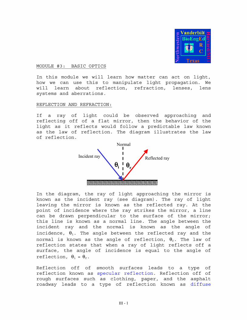
If a ray of light could be observed approaching andreflecting off of a flat mirror, then the behavior of thelight as it reflects would follow a predictable law knownas the law of reflection. The diagram illustrates the lawof reflection.
θθθθi θθθθr
Normal
Incident ray Reflected ray
In the diagram, the ray of light approaching the mirror isknown as the incident ray (see diagram). The ray of lightleaving the mirror is known as the reflected ray. At thepoint of incidence where the ray strikes the mirror, a linecan be drawn perpendicular to the surface of the mirror;this line is known as a normal line. The angle between theincident ray and the normal is known as the angle ofincidence, θi. The angle between the reflected ray and thenormal is known as the angle of reflection, θr. The law ofreflection states that when a ray of light reflects off asurface, the angle of incidence is equal to the angle ofreflection, θi = θr.
Reflection off of smooth surfaces leads to a type ofreflection known as specular reflection. Reflection off ofrough surfaces such as clothing, paper, and the asphaltroadway leads to a type of reflection known as diffuse

III - 2
reflection. The diagram below depicts two beams of lightincident upon a rough and a smooth surface.
The velocity of light, c, in a vacuum is about 3x10⁸ metersper second. In other media (glass, for example) thevelocity is less. The ratio of c to the actual velocity iscalled the refractive index, n:
vcn =
since µεµε
== 11 vandcoo
,
eem kkknoo
≅== µεµε
ε = electric permittivityµ = magnetic permeabilityke = dielectric constant (ε/εo)km = relative permeability (µ/µo)

III - 3
The color of the light and its frequency are the same inboth media. Therefore, the wavelength must shorten by thesame ratio as the velocity. You can think of this “slowingdown” of light in a transparent medium if you picture themedium composed of individual atoms or molecules that caninteract with the passing light by absorbing and re-emitting the light. This absorbed and re-emitted light isadded to the component passing through at c in such a waythat the sum is continually slowed down with respect to c.This continuous slowing down is equivalent to a phasevelocity less than c.
You can think of it like this: The electrons in the glassare driven to oscillate by the light’s E-field. This causesthe electrons to become dipoles themselves and they beginto re-radiate or scatter. However, only the wavelets inthe forward direction are IN PHASE and interfereconstructively. The others interfere destructively andcancel out.
air
glass
3 BASIC LAWS
Three fundamental laws describe how a wavefront of lightinteracts with a surface that forms the boundary betweenmaterials with different refractive indices e.g. air-glassinterface where air has a refractive index of 1 and glassis typically 1.5.
1) Incident, reflected, and transmitted waves lie all in thesame plane
2) Angle of incidence is equal to the angle of reflection
θi = θr

III - 4
3) SNELL’S LAW:
ni sin(θi) = nt sin(θt)
Where ni is index of refraction of the medium 1 and nt isindex of refraction of medium 2
Medium 1
Medium 2
θi θr
θt
ni
nt
Snell’s Law allows us to calculate the new direction ofpropagation when light passes through an interface betweentwo materials with different indices of refraction. Theangles are measured between the normal to the surface andthe light beam. Light passing from a material with a highindex of refraction to a material with a low index ofrefraction bends away from the normal whereas light passingfrom material with a low to material with a high index ofrefraction bends toward the normal.
FRESNEL’S EQUATIONS:
While Snell's law and the law of reflection tell ussomething about the direction in which reflected andrefracted light propagate, it does not say anything abouthow much light goes where. When light strikes the interfacebetween two materials with different indices of refraction,a fraction of the light is reflected (R) and a fraction istransmitted (T). The values of R and T may be calculatedusing Fresnel’s equations. It is important to realize that1) the sum of reflected and transmitted light must equalthe total incident light (since these are fractions R + T =1); and 2) the angle of polarization of the incident EMwave with respect to the plane of the incident material has

III - 5
an effect on the respective fractions of light that aretransmitted or reflected.
a) E-Field perpendicular to the plane of incidence
Medium 1
Medium 2
θi θr
θt
ni
nt
E
B
kE
B
B
k
kE
)(sin
)(sin
cosncosn
cosncosnr
E
E
ti
ti
ttii
ttii
i
rθ+θθ−θ−=
θ+θθ−θ== ⊥
⊥
⊥
r = amplitude reflection coefficient, ratio of reflected toincident electric field amplitudes.
)(sin
cossin2
cosncosn
cosn2t
E
E
ti
it
ttii
ii
i
t
θ+θθθ
=θ+θ
θ== ⊥
⊥
⊥
t = amplitude transmission coefficient, ratio oftransmitted to incident electric field amplitudes.

III - 6
b) E-field parallel to the plane of incidence
Medium 1
Medium 2
θi θr
θt
ni
nt
E
Bk
E
B
B
k
k
E
)(tan
)(tan
cosncosn
cosncosnr
E
E
ti
ti
itti
tiit//
//i
//r
θ+θθ−θ=
θ+θθ−θ==
)(cos)(sin
cossin2
cosncosn
cosn2t
E
E
titi
it
itti
ii//
//i
//t
θ−θθ+θθθ=
θ+θθ==
Given that,R = Reflectance (W/m2)T = Transmittance (W/m2)
When there is no absorption, R + T = 1, and
2//
ii
tt//
2
ii
tt
2////
2
tcosn
cosnT
tcosn
cosnT
rR
rR
θθ=
θθ=
=
=
⊥⊥
⊥⊥

III - 7
If θi = 0, the incident plane becomes undefined and2
it
it// nn
nnRRR
+−=== ⊥
( )2it
ti//
nn
nn4TTT
+=== ⊥
Examples:
1. What percent of light is reflected at the interface ofair (n = 1.0) to glass (n = 1.5) if the angle ofincidence is 0°?
Answer:2
it
it// nn
nnRRR
+−=== ⊥
%45.2
5.0
15.1
15.1RRR
22
// =
=
+−=== ⊥
This means that in a lens, which has 2 air-glassinterfaces, transmission through each interface = 96%. Thismeans that the transmission through the lens even itabsolutely non-absorbing is (0.96)2 = 0.9216. In other words7.84% of the light is lost due to reflection. Note thatthis property is multiplicative.
2. What percent of light is transmitted from air (n = 1.0)to glass (n = 1.4) if the angle of incidence is 48°. Assumethat the light is unpolarized.

III - 8
Answer:
The easiest way to approach this is to calculate thefraction of light that is reflected. Assuming noabsorption, the remainder is transmitted into the secondmedium.
First start with calculating the angle of refracted lightusing Snell's law. Given that
θi = 48o
reesdeg06.32)48(sin4.1
1sin
sinnsinn
1t
ttii
=
=θ
θ=θ
−
We can thus calculate the reflection coefficientsfor parallel and perperdicularly polarized lightusing Fresnel equations.
Substituting this into:
22//// rRandrR ⊥⊥ ==
Next we have to realize the light is unpolarized.Practically we can handle this in terms ofFresnel's equations by assuming that there is equalquantities of parallel and perpendicularlypolarized light and the simply take the average:
( )2//
221
2
RR//, rrR // +== ⊥
+⊥
⊥
0402.0)06.3248(sin
)06.3248(sin
)06.3248(tan
)06.3248(tan
2
1R
2
2
2
2=
+
−+
+
−
=
Thus R = 4.02%with T = 1 - R it follows that: T = 1 - 0.0402 = 0.9598
III - 9
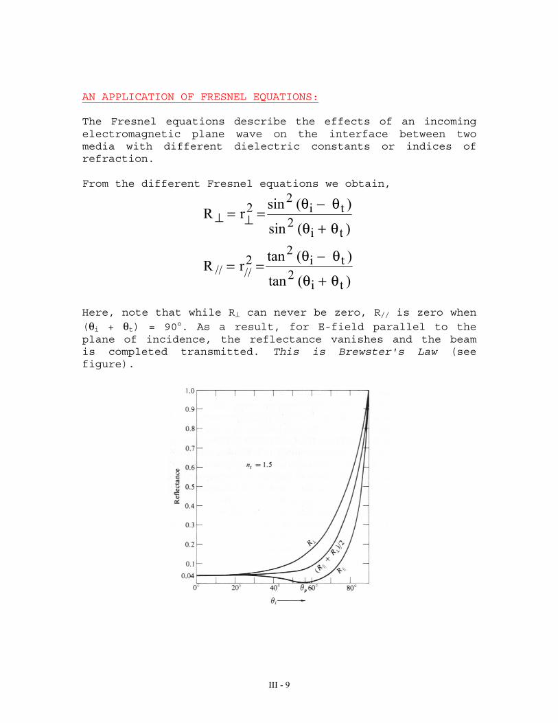
AN APPLICATION OF FRESNEL EQUATIONS:
The Fresnel equations describe the effects of an incomingelectromagnetic plane wave on the interface between twomedia with different dielectric constants or indices ofrefraction.
From the different Fresnel equations we obtain,
)(tan
)(tanrR
)(sin
)(sinrR
ti2
ti2
2////
ti2
ti2
2
θ+θ
θ−θ==
θ+θ
θ−θ== ⊥⊥
Here, note that while R⊥ can never be zero, R// is zero when(θi + θt) = 90°. As a result, for E-field parallel to theplane of incidence, the reflectance vanishes and the beamis completed transmitted. This is Brewster's Law (seefigure).

III - 10
Another way to look at this is that for parallel polarizedlight, there is an angle of incidence where thereflectivity = 0. This angle, known as the Brewster's anglecan be calculated by:
=θi
tn
nB arctan
LENSES AND LENS SYSTEMS:
A lens is typically made up of an optically translucentmaterial containing two or more refracting surfaces, atleast one of which is curved. Lenses may be used in anoptical system to modify a beam of light or to form animage of an object. There are a number of factors thatneed to be considered when characterizing a lens:
♦ DiameterThe diameter of a lens is typically chosen based on thesize of the beam and object that needs to be modified.
♦ Radius of CurvatureR determines how curved the lens is and the direction ofthe curvature. It also relates to the focal length of thelens (see lens equations section).
♦ Focal lengthFocal point is defined as the point at which parallelrays coming into the lens converge. The distance betweenthe center of the lens at this point is the focal lengthf of the lens. This point may be on the opposite side ofthe lens as in a convex lens or the same side as in aconcave lens.
♦ Transmission rangeAny given material will allow light of certainwavelengths to be transmitted while allowing others to beabsorbed. The lens material is chosen based on thewavelength of the light that is being modified. e.g.glass transmits well from 400 to 2500 nm, however quartzneeds to be used to transmit light in the UV while moreexotic materials need to be used for transmission furtherin the IR (for example: sapphire, CaF2, etc.).
♦ AberrationsAberrations are limitations in lens behavior that can bedetrimental to its performance. These include sphericalaberrations, chromatic aberrations, coma, andastigmatism.

III - 11
There are six kinds of lenses, divided in two maincategories; a) the positive or convex lenses and b) thenegative or concave lenses. The convex lenses have incommon that they are thicker in the center than at the edgewhile the concave lenses are thinner in the center than atthe edges:
Biconvex Plano-convex Meniscus convex
+ + +
R1 > 0 R1 = ∞ R1 > 0R2 < 0 R2 < 0 R2 > 0
_ _
Biconcave Plano-concave Meniscus concave
_
R1 < 0 R1 = ∞ R1 > 0R2 > 0 R2 > 0 R2 > 0
where,R1 = Radius of Curvature of the first lens surface from theleft)R2 = Radius of Curvature of the second lens surface (fromthe left)

III - 12
R2R1
Since all rays issuing from a source point will arrive atthe image point, any two rays will fix that point. Thereare three rays that are easiest to apply. Two of these makeuse of the fact that a ray passing through the focal pointwill emerge from the lens parallel to the optical axis andvice versa; the third is the undeviated ray through thecenter of the lens. They are illustrated below for bothpositive and negative lenses.
Ray 1
Ray 2
Ray 3
Ray 1
Ray 2
Ray 3
f
f
f
f
f
f
f f
f
f
f f
III - 13
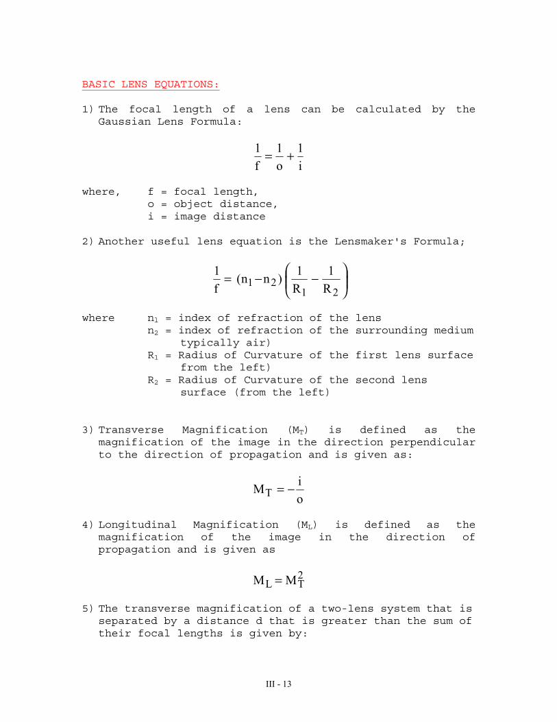
BASIC LENS EQUATIONS:
1) The focal length of a lens can be calculated by theGaussian Lens Formula:
i
1
o
1
f
1 +=
where, f = focal length,o = object distance,i = image distance
2) Another useful lens equation is the Lensmaker's Formula;
−−=
2121 R
1
R
1)nn(
f
1
where nl = index of refraction of the lensn2 = index of refraction of the surrounding medium
typically air)R1 = Radius of Curvature of the first lens surface
from the left)R2 = Radius of Curvature of the second lens
surface (from the left)
3) Transverse Magnification (MT) is defined as themagnification of the image in the direction perpendicularto the direction of propagation and is given as:
o
iMT −=
4) Longitudinal Magnification (ML) is defined as themagnification of the image in the direction ofpropagation and is given as
2TL MM =
5) The transverse magnification of a two-lens system that isseparated by a distance d that is greater than the sum oftheir focal lengths is given by:
III - 14
1111
21T fo)fo(d
ifM
−−=
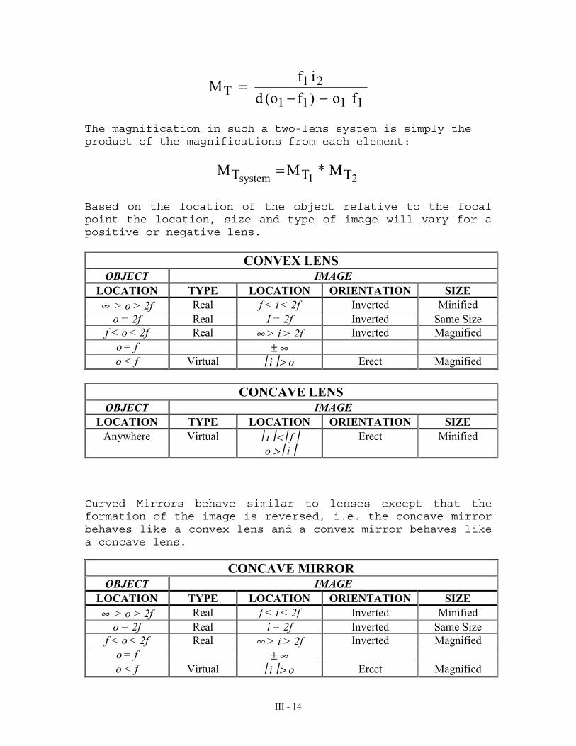
The magnification in such a two-lens system is simply theproduct of the magnifications from each element:
21system TTT M*MM =
Based on the location of the object relative to the focalpoint the location, size and type of image will vary for apositive or negative lens.
CONVEX LENSOBJECT IMAGE
LOCATION TYPE LOCATION ORIENTATION SIZE∞ > o > 2f Real f < i < 2f Inverted Minified
o = 2f Real I = 2f Inverted Same Sizef < o < 2f Real ∞ > i > 2f Inverted Magnified
o = f ± ∞o < f Virtual i > o Erect Magnified
CONCAVE LENSOBJECT IMAGE
LOCATION TYPE LOCATION ORIENTATION SIZEAnywhere Virtual i < f
o > iErect Minified
Curved Mirrors behave similar to lenses except that theformation of the image is reversed, i.e. the concave mirrorbehaves like a convex lens and a convex mirror behaves likea concave lens.
CONCAVE MIRROROBJECT IMAGE
LOCATION TYPE LOCATION ORIENTATION SIZE∞ > o > 2f Real f < i < 2f Inverted Minified
o = 2f Real i = 2f Inverted Same Sizef < o < 2f Real ∞ > i > 2f Inverted Magnified
o = f ± ∞o < f Virtual i > o Erect Magnified

III - 15
CONVEX MIRROROBJECT IMAGE
LOCATION TYPE LOCATION ORIENTATION SIZEAnywhere Virtual i < f
o > iErect Minified
EXAMPLES:
1. Construct the rays to form the image for a positive lensgiven that the focal length of the lens is 2 m and anobject (1.5 m high) is placed at a distance of 3.5 m fromthe lens.
Answer:Given,f = 2 mo = 3.5 mh(object) = 1.5 m
(Hint: To construct the image, draw the three raysdescribed earlier)
o = 3.5 m
if = 2 m
1.5 m
Given that,

III - 16
214.05.3
1
2
1
i
1i
1
o
1
f
1
=−=
+=
Thus i = 4.67 m
The magnification is given as,
33.15.3
67.4
o
iMT ==−=
Therefore, an object 1.5 m high will be magnified 1.33times to yield an image 1.995 m high. This image is real,inverted and magnified.
2. Construct the rays to form the image for a lens withfocal length -10 cm and an object that is placed at adistance of 10 cm from the lens. What kind of image doyou get?
Answer:Given,o = 10 cmf = -10 cm, therefore it is a concave (negative) lens.
Draw rays to construct the image.
o = 10 cm
f = 10 cmi
III - 17
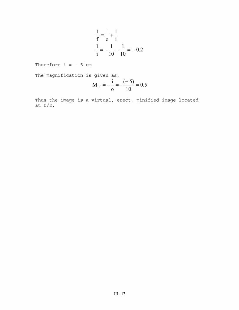
2.010
1
10
1
i
1i
1
o
1
f
1
−=−−=
+=
Therefore i = - 5 cm
The magnification is given as,
5.010
)5(
o
iMT =−−=−=
Thus the image is a virtual, erect, minified image locatedat f/2.

III - 18
ABERRATIONS:
The formulas developed earlier for image formation byspherical reflecting and refracting surfaces are, ofcourse, only approximately correct. In deriving thoseformulas it was necessary to assume paraxial rays, raysboth near to the optical axis and making small angles withit. However, in considering these lens situations willarise when these assumptions are no longer valid andaberrations are observed.
1. Spherical AberrationsSpherical aberrations occur due to the severe curvatureof short focal length or smaller lenses because raysincident on the outer regions of a lens bend more thanthe rays towards the center, causing the image to appearout of focus.
Spherical aberrations are corrected by:• using a larger lens• orienting the lens correctly• using the right type of lens
2. ComaComa is an off-axis aberration that is nonsymmetricalabout the optical axis. This arises from the dependenceof transverse magnification on the ray height at thelens. Because of coma, an off-axis object point isimaged as a blurred shape that resembles a comet with ahead and a tail. This type of image can be minimized byappropriate selection of the diameter of the lens to beused.

III - 19
3. AstigmatismWhen an object point lies far away from the optical axis,the incident cone of rays will strike the lensasymmetrically giving rise to astigmatism. If the raysincident on the lens in the plane of the paper (tangentialplane) has a given focal length, then the rays in the planethat is obliquely angled with respect to the paper(sagittal plane) has a different focal length. Thus, forthe incident conical bundle of rays, the cross-section ofbeam as it leaves the lens is initially circular andgradually becomes elliptical until it meets in a line atthe focal point that is tangential to the plane of thepaper.
4. Field of CurvatureIn this type of aberration, a given planar object isimaged on a parabolic surface instead of a plane as canbe seen in the figure.

III - 20
5. DistortionDistortion shows up as a variation in the transversemagnification for points of the object away from theoptical axis. In other words, distortion occurs becausedifferent areas of the lens have different focal lengthsand different transverse magnifications.
Object Pincushion Distortion Barrel Distortion
6. Chromatic AberrationChromatic aberration occurs for incident rays that containmany wavelengths. Since the index of refraction varies withwavelength, the focal properties of a simple lens will varyas well. The refractive index is higher for blue lightthan red light. Therefore, the focal length of a convexlens is shorter for blue light than red light.

III - 21
Chromatic aberration can be corrected for using anachromatic doublet. An achromatic doublet consists of aconvex and concave lens made of different materialscemented together. By choosing materials with appropriaterefractive indices, you can create a doublet that will havethe same focal length at two wavelengths. The two lensescorrect for each other and a focal point is found somewherein the middle.
REFERENCES:
1. Hecht, Eugene. (1987) Optics. Addison-Wesley PublishingCompany, Reading, MA.
2. Pedrotti F and Pedrotti L. (1993) Introduction to Optics, Prentice-Hall, Upper Saddle River, NJ.