Embed Size (px)
Citation preview
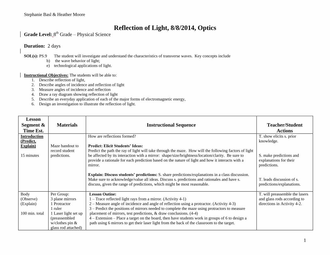
Stephanie Basl & Heather Moore
1
Reflection of Light, 8/8/2014, Optics Grade Level: 8
th Grade – Physical Science
Duration: 2 days
SOL(s): PS.9 The student will investigate and understand the characteristics of transverse waves. Key concepts include
b) the wave behavior of light;
e) technological applications of light.
Instructional Objectives: The students will be able to:
1. Describe reflection of light,
2. Describe angles of incidence and reflection of light
3. Measure angles of incidence and reflection
4. Draw a ray diagram showing reflection of light
5. Describe an everyday application of each of the major forms of electromagnetic energy,
6. Design an investigation to illustrate the reflection of light.
Lesson
Segment &
Time Est.
Materials
Instructional Sequence
Teacher/Student
Actions Introduction
(Predict,
Explain)
15 minutes
Maze handout to
record student
predictions.
How are reflections formed?
Predict: Elicit Students’ Ideas:
Predict the path the ray of light will take through the maze. How will the following factors of light
be affected by its interaction with a mirror: shape/size/brightness/location/clarity. Be sure to
provide a rationale for each prediction based on the nature of light and how it interacts with a
mirror.
Explain: Discuss students’ predictions: S. share predictions/explanations in a class discussion.
Make sure to acknowledge/value all ideas. Discuss s. predictions and rationales and have s.
discuss, given the range of predictions, which might be most reasonable.
T. show elicits s. prior
knowledge.
S. make predictions and
explanations for their
predictions.
T. leads discussion of s.
predictions/explanations.
Body
(Observe)
(Explain)
100 min. total
Per Group:
3 plane mirrors
1 Protractor
1 ruler
1 Laser light set up
(preassembled
w/clothes pin &
glass rod attached)
Lesson Outine:
1 – Trace reflected light rays from a mirror. (Activity 4-1)
2 – Measure angle of incidence and angle of reflection using a protractor. (Activity 4-3)
3 – Predict the positions of mirrors needed to complete the maze using protractors to measure
placement of mirrors, test predictions, & draw conclusions. (4-4)
4 – Extension – Place a target on the board, then have students work in groups of 6 to design a
path using 6 mirrors to get their laser light from the back of the classroom to the target.
T. will preassemble the lasers
and glass rods according to
directions in Activity 4-2.

Stephanie Basl & Heather Moore
2
Lesson
Segment &
Time Est.
Materials
Instructional Sequence
Teacher/Student
Actions
4-1: 30 min.
Animation:
15 min.
4-3: 30 min.
4-4: 20 min.
Extend:
20 min.
Paper Maze (from
prediction)
Handouts for 4-1,
4-3, and 4-4.
Internet access:
Physics Classroom
Major Questions:
1 – How is angle of incidence related to angle of reflection?
2 – How can the angle of incidence determine the path of reflected angle?
3 – What is a real world application of the reflection law?
Safety:
Do not point the laser, or its reflection, at anyone.
Handle glass objects carefully. Report any damaged materials to the teacher immediately.
Directions:
Using Lab 4, Section 1, students will work in groups to determine how rays of light will reflect off
the surface of mirrors. Students will guide themselves through the activity using the hand out
provided. Teacher will monitor student’s productivity during the activity, then bring the class back
together to discuss the student findings and informally assess student understanding.
Direct students to Physics Classroom.
Students will read the material provided on the webpage, view the animation, and complete the
questions at the bottom of the page before moving on to Lab 4-3.
Using Lab 4, Section 3, students will work in groups to verify and understand the Law of
Reflection. Students will guide themselves through the activity using the hand out provided.
Teacher will monitor student’s productivity during the activity, then bring the class back together
to discuss the student findings and informally assess student understanding.
Using Lab 4, Section 4, students will work in groups to demonstrate their understanding of the Law
of Reflection. Students will direct the path of light ray around a maze using 3 plane mirrors.
Students will first determine the angle of the light path using a protractor, then apply that
information to calculate the angle of reflection and the position of each mirror. Teacher will
monitor student’s productivity during the activity, then bring the class back together to discuss the
student findings and informally assess student understanding.
Extension: Students will work collaboratively with another group in order to create a maze using 6
mirrors which will direct a ray of light from the back of the classroom to the target on the board at
the front of the classroom. Students will make observation notes including the brightness and
clarity of the light ray, as well as the angles of incidence and reflection. Teacher will monitor
student’s productivity during the activity, then bring the class back together to discuss the student
findings and informally assess student understanding.
S. work in small groups to
collect data on angle of
incidence and angle of
reflection.
T. circulates and asks s. about
their observations and
explanations for their
observations.
T. leads whole class
discussion.
Stephanie Basl & Heather Moore
3
Lesson
Segment &
Time Est.
Materials
Instructional Sequence
Teacher/Student
Actions Observe:
Students will observe reflected rays using laser pointers and a mirror. They will draw and label
the angle of incidence and the angle of reflection. They will use a protractor to measure the
degree of each angle from the normal. Using this information, they will predict the locations and
angles that mirrors should be placed in order to complete the maze.
Explain: Students will state that the angle of reflections is equal to the angle of incidence. With this
understanding, the students should be able to explain that if a protractor is used to measure the
incoming beam of light from the laser to the mirror will determine the location of the outgoing ray
after reflection. The students will use this law of reflection to explain the positions of mirrors in
the paper maze as well as the classroom maze.
Closure
(Explain,
con’t)
20 min.
Total Time =
135 min.
Equipment to show
YouTube video
clip
Explain (continued): Whole-class discussion of small group observations/explanations.
Closure: Reiterate patterns s. noticed, provide scientific vocabulary and scientific explanation for
observations:
When light is emitted from a laser through a glass rod, the light ray travels in a straight line. If a
mirror is placed in the path of the light, the resulting reflected angle will be equal to the angle of
incidence. This is call the Law of Reflection. If the mirror has 2 surfaces (front surface & back
silver surface), then light will reflect from both locations.
1. The thickness of mirror will determine how far about the two reflected angles are from
each other.
2. Depending on the thickness, the clarity of the reflected beams, possibly even split the light
into two separate beams.
3. The brightness doesn’t change with reflection.
4. If a curved mirror is used, the direction of the reflected angle will change, but the angle of
incidence will still equal the angle of reflection.
Extension question: Based on what you know about the law of reflection, how is the angle of
incidence related to the angle of reflection? Why? Does a mirror only reflect one ray of light?
Why do you think so? How do you know where a reflected light ray will appear? Explain.
In fiber optics, pulses of light are shined into reflective cables. Predict how the light pattern will
travel through the cable. Will the light have the same angle of incidence/reflection at all times?
Explain. (Hint: Image of Fiber Optics Cable)
T. leads whole class
discussion.
T. might want to show these 2
video clips to help explain
fiber optics.
How they Work?
How it is Made?
Assessment
Plan:
1. What is the relationship between the angle of incidence and the angle of reflection?
2. How is a light reflection affected by the size and shape of a mirror?
3. List 2 real world applications which use the Law of Reflection. (Draw a diagram to show
Stephanie Basl & Heather Moore
4
Lesson
Segment &
Time Est.
Materials
Instructional Sequence
Teacher/Student
Actions how it is used.)

Stephanie Basl & Heather Moore
5
Home Lab 4 (______ of 56 Points)
Reflection of Light Rays Overview: With a simple flat mirror, paper, and a ruler we can demonstrate how we see reflections of different objects in mirrors.
Activity 4 - 1: Tracing reflected light rays from a mirror.
Objectives: To determine how rays of light reflect off the surface of mirrors.
Materials Included:
• A flat mirror, something to make it stand up (clips, clothes pens, block or book)
Materials not Included • Paper, pen or pencil, ruler and straight pin
Procedure: 1. Take a sheet of any white 8.5”x11” paper – fold it in half then with a ruler, draw a line across the paper on the fold to divide the paper into two equal halves.
Stephanie Basl & Heather Moore
6
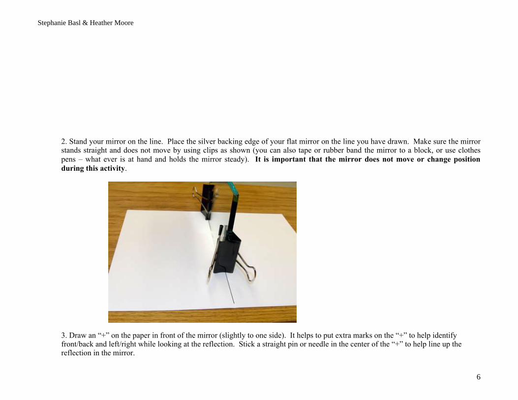
2. Stand your mirror on the line. Place the silver backing edge of your flat mirror on the line you have drawn. Make sure the mirror stands straight and does not move by using clips as shown (you can also tape or rubber band the mirror to a block, or use clothes
pens – what ever is at hand and holds the mirror steady). It is important that the mirror does not move or change position
during this activity.
3. Draw an “+” on the paper in front of the mirror (slightly to one side). It helps to put extra marks on the “+” to help identify front/back and left/right while looking at the reflection. Stick a straight pin or needle in the center of the “+” to help line up the reflection in the mirror.

Stephanie Basl & Heather Moore
7
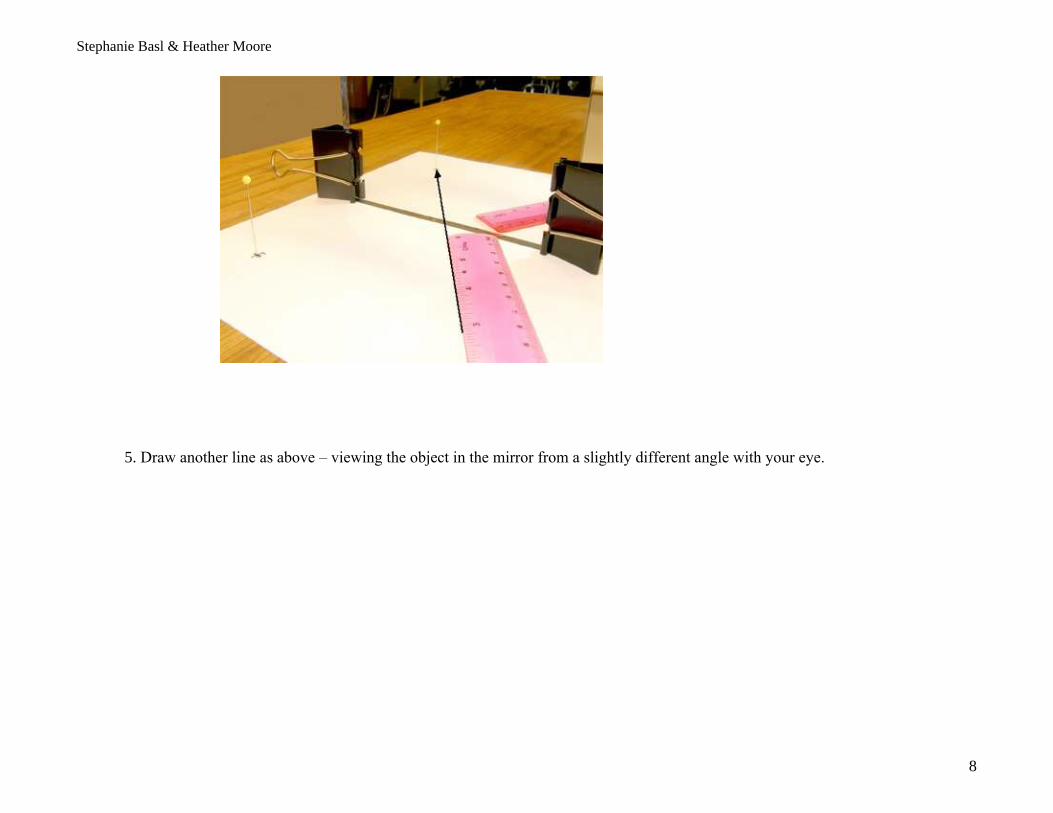
4. Get your eye down to the level of the paper on the table and look at the reflection of the +/pin in the mirror. From the position where your eye sees the reflected image in the mirror – take a ruler and draw a line to where the +/pin appears to be in the mirror. Line the ruler up as if you were making a billiards shot - be careful - draw the line exactly toward the mirror where the image seems to appear.
Stephanie Basl & Heather Moore
8
5. Draw another line as above – viewing the object in the mirror from a slightly different angle with your eye.

Stephanie Basl & Heather Moore
9
6. You should now have two lines drawn from the two positions where your eye viewed the object toward the mirror. These lines represent the rays of light that are reflected from the object – off the mirror – to your eyes. We will now remove the mirror and finish our light ray diagram.

Stephanie Basl & Heather Moore
10
7. Set the mirror aside - we now have just the two lines on the paper directed toward the line that divided the paper in half (where the mirror was placed). With a ruler, extend your two lines to the mirror and then continue to extent the lines until the lines meet behind the line of the mirror (as shown here). The lines behind the mirror meet at the position where the image appears to be (behind the mirror). Images that appear behind a mirror are known as virtual images. You will need to photograph or scan this diagram and submit it with this assignment.
8. Fold your paper in half along the line where the mirror was placed and look through the paper by holding it up to the light (it should look like the picture here). If the lines behind the mirror go through the “+”object – you have done an excellent job drawing your lines.

Stephanie Basl & Heather Moore
11
9. This diagram was made to explain the picture above. The dashed lines on the left are rays of light coming from the object toward the mirror line at bottom of the picture (where you folded the paper). These rays reflect off the mirror exactly to the positions where your eyes viewed the image in the mirror. Note that the angle that rays come to the mirror (angle of incidence) and the angle that the rays are reflected from the mirror (angle of reflection) appear to be the same angles.

Stephanie Basl & Heather Moore
12
Stephanie Basl & Heather Moore
13
Activity 4 - 2: Making a laser line from a laser spot
Objectives: To make a laser line from a laser spot using a glass rod as a lens
Materials Included: • Laser pointer, glass rod cylinder
Materials not Provided: • Transparent scotch tape, small metal file, wooden clothespin
Overview:
About the Laser pointer
The laser pointer emits red light of wavelength 650 nanometers with less than 5 milliwatts of power. Please read the label on the laser carefully and avoid direct contact with your eye. The laser comes powered by two AAA 1.55 volt alkaline batteries. If the laser light is left on continuously, the batteries will die quickly, so shut it off when not in use.
Why use a glass rod cylinder?
The laser you use in the following investigations requires an intense line of red light. As seen in the pictures below, directing the Laser light through a cylindrical piece of glass or clear plastic rod can cause this effect. The rod acts as a lens to spread out the Laser light in one direction. Note from the picture - the orientation of the rod compared to the line of light. We will investigate this effect in detail in the Home Lab on Refraction.

Stephanie Basl & Heather Moore
14
Laser pointed at Wall Laser light through a glass rod to Wall
Procedure:
1. Using a small metal file, scribe (cut) a short mark across the glass rod about 1-2 inches from one end of the rod as show in the picture.

Stephanie Basl & Heather Moore
15
2. Pinch the glass rod at the short end near the scribe mark between thumb and forefinger and do the same on the other side of the mark with your other hand. Do this carefully so you do not cut yourself.

Stephanie Basl & Heather Moore
16
3. Now try to bend the rod. It will cleanly snap at the scribe mark. The longer the shorter length of rod, the easier it is to break.

Stephanie Basl & Heather Moore
17
4. Hold the 1-2 inch glass rod next to the laser emission aperture in your laser pointer and tape it securely together. If you use transparent scotch tape the laser beam can go right through the tape without much loss of intensity, or emissivity.
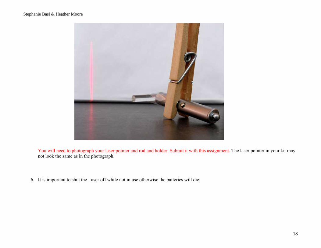
5. Use a clothespin to hold the laser button on while taking your measurements as shown in the figure below.
Stephanie Basl & Heather Moore
18
You will need to photograph your laser pointer and rod and holder. Submit it with this assignment. The laser pointer in your kit may not look the same as in the photograph.
6. It is important to shut the Laser off while not in use otherwise the batteries will die.
Stephanie Basl & Heather Moore
19
Activity 4 - 3: Verifying the Law of Reflection
Objectives: To verify and understand the Law of Reflection.
Materials Included: • Laser pointer, glass rod cylinder, flat mirror, paper protractor on last page and rulert
Materials not Provided: • Support for mirror (wooden clothes pen, clamps, etc.), paper, pen or pencil
1. From your experience with reflection in Activity 4-1 - describe how a single beam of light will reflect from the surface of a mirror:
Solution: Back off the mirror with a reflection angle about equal to the angle of incidence.
2. Make a prediction - will the angle that the beam of light reflects from the surface of the mirror be smaller, larger, or the same as the angle of the original beam to the surface of the mirror?
Solution: I predict that the angle of incidence is equal to the angle of reflection.
Procedure:
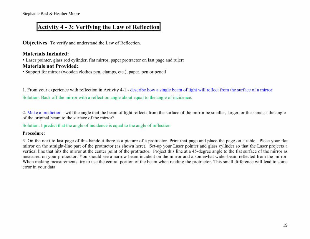
3. On the next to last page of this handout there is a picture of a protractor. Print that page and place the page on a table. Place your flat mirror on the straight-line part of the protractor (as shown here). Set-up your Laser pointer and glass cylinder so that the Laser projects a vertical line that hits the mirror at the center point of the protractor. Project this line at a 45-degree angle to the flat surface of the mirror as measured on your protractor. You should see a narrow beam incident on the mirror and a somewhat wider beam reflected from the mirror. When making measurements, try to use the central portion of the beam when reading the protractor. This small difference will lead to some error in your data.

Stephanie Basl & Heather Moore
20
4. Make 2 dots along each projected Laser light line then using a ruler, trace along the projected Laser light line to mark the incident and reflected rays onto the protractor paper (resulting in the picture below when the Laser is turned off). Remove the mirror from the paper then extend the ray lines to the mirror line.
Stephanie Basl & Heather Moore
21
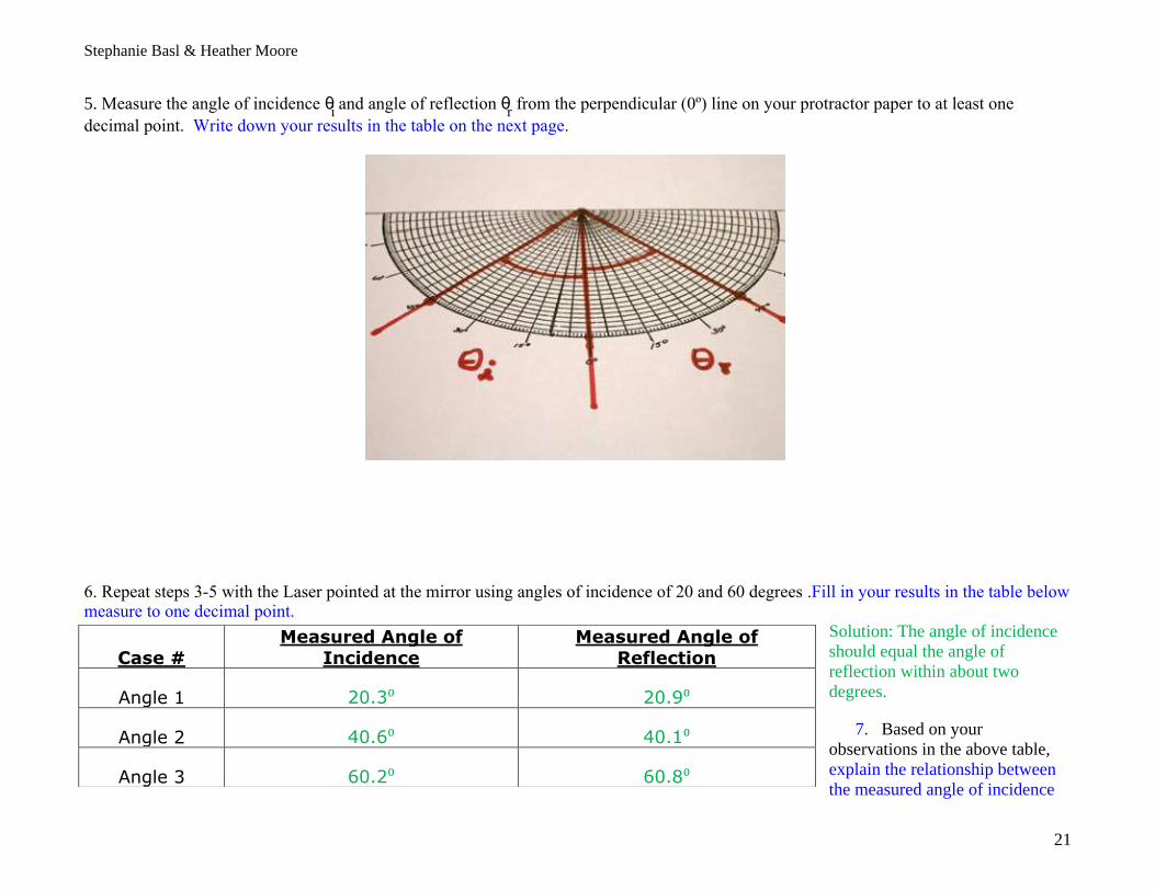
5. Measure the angle of incidence θi and angle of reflection θ
r from the perpendicular (0º) line on your protractor paper to at least one
decimal point. Write down your results in the table on the next page.
6. Repeat steps 3-5 with the Laser pointed at the mirror using angles of incidence of 20 and 60 degrees .Fill in your results in the table below measure to one decimal point.
Solution: The angle of incidence
should equal the angle of
reflection within about two
degrees.
7. Based on your
observations in the above table,
explain the relationship between
the measured angle of incidence
Case # Measured Angle of
Incidence Measured Angle of
Reflection
Angle 1 20.3⁰ 20.9⁰
Angle 2 40.6⁰ 40.1⁰
Angle 3 60.2⁰ 60.8⁰

Stephanie Basl & Heather Moore
22
and measured angle of reflection.
Solution: The angle of incidence is equal of reflection within experimental error
8. If you use a much thicker mirror (shown below) than what is in the kit, you can barely see three separately reflected beams. The most intense reflected beam is actually reflected from the back of the mirror. The faint beam on the top-side is reflected from the front surface and the faint beam on the bottom side is reflected from the back, then front, and then back again. Based on these observations, how would you explain the appearance of your reflected beam from your thinner mirror? Solution: The multiple beams would be closer together for a thinner mirror because the separation between them is proportional to the thickness of the mirror. Also, part of the beam may have a halo on it from the lens in the laser pointer. That has nothing to do with the reflection angle.
Activity 4 - 4: Light Maze Prediction
Incident Beam
Reflected Beam

Stephanie Basl & Heather Moore
23
Objectives:
To demonstrate your understanding of the Law of Reflection - you will direct a path of light around an obstacle course by reflecting it in three different mirrors.
Materials Included: • Laser pointer, glass rod cylinder, flat mirror, paper protractor on last page
Materials not Provided: • Support for 3 mirrors (wooden clothes pen, clamps, etc.), paper, pen or pencil, and a ruler
Procedure: 1. On the last page of this handout is a page similar to the page shown below – printout the page.
2. From the starting point (in the upper left hand corner) a line goes through 3 changes in direction to finally arrive at the finish point (in the lower left hand corner). It will be your job to set up mirrors to reflect Laser light down these paths to the finish point. In the three places where the lines change directions – draw a short line to represent how you would place mirrors to reflect light to follow the path of lines on the drawing (see completed diagram below).

Stephanie Basl & Heather Moore
24
What is your reason for positioning the lines in this particular manner?
Solution: Knowing that the angle of incidence equals the angle of reflection you can position each mirror so that the ray of light when reflected will strike subsequent mirrors until you reach the last mirror.
Test your predictions
1. Place mirrors at the 3 locations you have drawn on the page (see picture here).
2. Using the glass cylinder to make a vertical line - direct the Laser Pointer to shine a line through the starting spot, down the first line to the first mirror. The result should cause the light to reflect through the three mirrors to the finish spot at the bottom of the page.
3. How well did you do? Mark 2 points along each Laser path so you can draw a straight line showing the path of the Laser light. You will need to photograph or scan your diagram and submit it with this assignment.
4. Try again and see if you can do better.
5. Discuss where your main problems or misconceptions were when you tried this activity the first time:

Stephanie Basl & Heather Moore
25
Solution: Answers will vary. I noticed that the positions of the mirrors had to be precisely located to track the beam to the last mirror. If you were off a little in angle, it seemed to be magnified.