Embed Size (px)
Citation preview
Publications of the DLR elibelibelib
This is the author’s copy of the publication as archived with the DLR’s electronic library at http://elib.dlr.de. Pleaseconsult the original publication for citation.
Multiphysical Simulation of a Semi-Autonomous Solar Powered HighAltitude Pseudo-SatelliteReiko Müller and Jane Jean Kiam and Federico MothesWith advances made in the fields of energy generation from renewable sources, airborne electrical propulsion, and autonomous systemoperation, much activity has been directed towards the development of so called high altitude pseudo satellites (HAPS) in recent years, withZephyr (Airbus) and Aquila (Facebook) as prominent examples. Compared to classical orbital satellites, these are designed to require lowerdeployment costs and to offer a high flexibility in operational tasks and a long mission endurance. In the project StraVARIA, the goal wasto develop a high-fidelity multiphysical simulation of such a HAPS, including a long-term mission planner, a reactive guidance system forweather avoidance, a flight control system with protections, a 6-DoF model with solar-electric propulsion system, and a comprehensiveenvironment simulation with 4-D wind and turbulence. Due to the long mission duration, the mission planner and guidance system offer anincreased autonomy level compared to standard operator controlled UAVs, however human input is still required for high level planning. Theacausal and object-oriented modeling language Modelica has been used to create the integrated simulation model, enabling a modular anddetailed modeling approach. By automatic code generation and optimization, simulation efficiency is improved, which is an important factorwhen considering long-term missions. Results of the integrated simulation show that missions like area surveillance and communicationrelay are possible whenever adverse weather conditions can be avoided. Ascending to and descending from mission altitude of approximately18 km also poses a threat to the lightweight HAPS construction since layers of stronger winds and atmospheric disturbance have to bepassed. To this end, simulated example missions over Bavaria are presented showcasing these effects, where mission success is ensured bymeans of the long term mission planner, the reactive guidance, and the inner-level protections implemented in the flight control system.
Keywords: aerospace propulsion;artificial satellites;autonomous aerial vehicles;control engineering computing;object-orientedlanguages;optimisation;program compilers;semiautonomous solar powered high altitude pseudosatellite;energy generation;renewablesources;airborne electrical propulsion;autonomous system operation;high-fidelity multiphysical simulation;long-term missionplanner;reactive guidance system;weather avoidance;flight control system;6-DoF model;solar-electric propulsion system;turbulence;longmission duration;automatic code generation;optimization;mission altitude;lightweight HAPS construction;long term missionplanner;environment simulation;orbital satellites;object-oriented modeling language;Modelica;unmanned aerial vehicle;size 18.0 km;Objectoriented modeling;Atmospheric modeling;Aircraft;Mathematical model;Adaptation models;Meteorology;Control systems
Copyright Noticec 2018 IEEE. Personal use of this material is permitted. However, permission to reprint/republish this material for
advertising or promotional purposes or for creating new collective works for resale or redistribution to servers or lists, orto reuse any copyrighted component of this work in other works must be obtained from the IEEE.
Citation Notice[1] Reiko Müller, Jane Jean Kiam, and Federico Mothes. Multiphysical Simulation of a Semi-Autonomous Solar Powered
High Altitude Pseudo-Satellite. In 2018 IEEE Aerospace Conference, pages 1–16. Institute of Electrical and ElectronicsEngineers (IEEE), March 2018. doi:10.1109/AERO.2018.8396531.
@INPROCEEDINGS{8396531,author={Reiko M{\"u}ller and Jane Jean Kiam and Federico Mothes},booktitle={2018 IEEE Aerospace Conference},title={{Multiphysical Simulation of a Semi-Autonomous Solar Powered High Altitude Pseudo-Satellite}},organization={Institute of Electrical and Electronics Engineers (IEEE)},year={2018},volume={},number={},pages={1-16},doi={10.1109/AERO.2018.8396531},abstract={With advances made in the fields of energy generation from renewable sources, airborne electrical propulsion, and autonomous system operation, much activity
has been directed towards the development of so called high altitude pseudo satellites (HAPS) in recent years, with Zephyr (Airbus) and Aquila (Facebook) asprominent examples. Compared to classical orbital satellites, these are designed to require lower deployment costs and to offer a high flexibility in operationaltasks and a long mission endurance. In the project StraVARIA, the goal was to develop a high-fidelity multiphysical simulation of such a HAPS, including a long-
term mission planner, a reactive guidance system for weather avoidance, a flight control system with protections, a 6-DoF model with solar-electric propulsionsystem, and a comprehensive environment simulation with 4-D wind and turbulence. Due to the long mission duration, the mission planner and guidance system offeran increased autonomy level compared to standard operator controlled UAVs, however human input is still required for high level planning. The acausal and object-oriented modeling language Modelica has been used to create the integrated simulation model, enabling a modular and detailed modeling approach. By automatic codegeneration and optimization, simulation efficiency is improved, which is an important factor when considering long-term missions. Results of the integrated
simulation show that missions like area surveillance and communication relay are possible whenever adverse weather conditions can be avoided. Ascending to anddescending from mission altitude of approximately 18 km also poses a threat to the lightweight HAPS construction since layers of stronger winds and atmosphericdisturbance have to be passed. To this end, simulated example missions over Bavaria are presented showcasing these effects, where mission success is ensured bymeans of the long term mission planner, the reactive guidance, and the inner-level protections implemented in the flight control system.},
keywords={aerospace propulsion;artificial satellites;autonomous aerial vehicles;control engineering computing;object-oriented languages;optimisation;program compilers;semiautonomous solar powered high altitude pseudosatellite;energy generation;renewable sources;airborne electrical propulsion;autonomous system operation;high-fidelity multiphysical simulation;long-term mission planner;reactive guidance system;weather avoidance;flight control system;6-DoF model;solar-electricpropulsion system;turbulence;long mission duration;automatic code generation;optimization;mission altitude;lightweight HAPS construction;long term missionplanner;environment simulation;orbital satellites;object-oriented modeling language;Modelica;unmanned aerial vehicle;size 18.0 km;Object oriented modeling;Atmospheric modeling;Aircraft;Mathematical model;Adaptation models;Meteorology;Control systems},
ISSN={},month={March}}

Multiphysical Simulation of a Semi-Autonomous SolarPowered High Altitude Pseudo-Satellite
Reiko MüllerGerman Aerospace Center (DLR)
Institute of System Dynamics and Control (SR)Münchener Strasse 20
82234 Wessling, [email protected]
Jane Jean KiamUniversität der Bundeswehr München
Institut für FlugsystemeWerner-Heisenberg-Weg 3985579 Neubiberg, Germany
[email protected] Mothes
Hochschule MünchenFakultät für Flugzeugtechnik
Lothstr. 6480335 München, [email protected]
Abstract—With advances made in the fields of energy generationfrom renewable sources, airborne electrical propulsion, andautonomous system operation, much activity has been directedtowards the development of so called high altitude pseudo satel-lites (HAPS) in recent years, with Zephyr (Airbus) and Aquila(Facebook) as prominent examples. Compared to classical or-bital satellites, these are designed to require lower deploymentcosts and to offer a high flexibility in operational tasks and along mission endurance. In the project StraVARIA, the goalwas to develop a high-fidelity multiphysical simulation of sucha HAPS, including a long-term mission planner, a reactiveguidance system for weather avoidance, a flight control systemwith protections, a 6-DoF model with solar-electric propulsionsystem, and a comprehensive environment simulation with 4-Dwind and turbulence. Due to the long mission duration, the mis-sion planner and guidance system offer an increased autonomylevel compared to standard operator controlled UAVs, howeverhuman input is still required for high level planning. The acausaland object-oriented modeling language Modelica has been usedto create the integrated simulation model, enabling a modularand detailed modeling approach. By automatic code generationand optimization, simulation efficiency is improved, which isan important factor when considering long-term missions. Re-sults of the integrated simulation show that missions like areasurveillance and communication relay are possible wheneveradverse weather conditions can be avoided. Ascending to anddescending from mission altitude of approximately 18 km alsoposes a threat to the lightweight HAPS construction since lay-ers of stronger winds and atmospheric disturbance have to bepassed. To this end, simulated example missions over Bavariaare presented showcasing these effects, where mission success isensured by means of the long term mission planner, the reactiveguidance, and the inner-level protections implemented in theflight control system.
TABLE OF CONTENTS
REFERENCES . . . . . . . . . . . . . . . . . . . . . . . . . . . . . . . . . . . . . . . . 11. INTRODUCTION . . . . . . . . . . . . . . . . . . . . . . . . . . . . . . . . . . . 12. MULTIPHYSICAL SIMULATION MODEL . . . . . . . . . . 23. FLIGHT CONTROL SYSTEM . . . . . . . . . . . . . . . . . . . . . . . 64. MISSION PLANNER . . . . . . . . . . . . . . . . . . . . . . . . . . . . . . . 75. WEATHER AVOIDANCE MODULE . . . . . . . . . . . . . . . . . 96. INTERFACING AND PERFORMANCE . . . . . . . . . . . . . . 107. SIMULATION RESULTS . . . . . . . . . . . . . . . . . . . . . . . . . . . 11
978-1-5386-2014-4/18/$31.00 c©2018 IEEE
8. SUMMARY AND OUTLOOK . . . . . . . . . . . . . . . . . . . . . . . . 14ACKNOWLEDGMENTS . . . . . . . . . . . . . . . . . . . . . . . . . . . . . . . 14REFERENCES . . . . . . . . . . . . . . . . . . . . . . . . . . . . . . . . . . . . . . . . 14BIOGRAPHY . . . . . . . . . . . . . . . . . . . . . . . . . . . . . . . . . . . . . . . . . 16
1. INTRODUCTIONIncreasing autonomy levels has been a prevalent topic inthe design of Unmanned Aerial Vehicles (UAVs) since thebeginning of the 90’s. The well-known 3-D (dull, dirtyand dangerous) notion describes activities or missions whichdrive the development of many autonomous systems, not onlyin the aerospace field. The main goal is to reduce humaninteraction in tasks
• involving repetitive actions while not requiring a lot ofattention and input (for example reconaissance missions orcommunication relay),• performed in unsafe environments where human presencerequires complex technical solutions (for example contami-nated areas),• considered as high-risk missions / dangerous (i.e. opera-tions in war theatres).
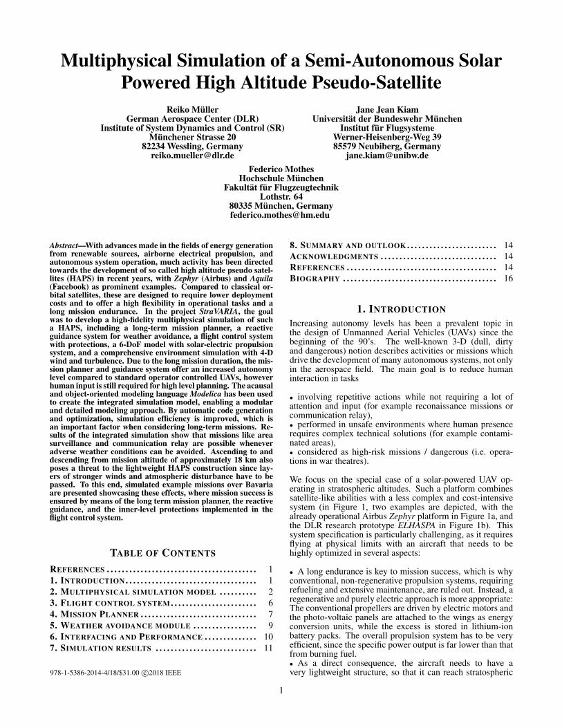
We focus on the special case of a solar-powered UAV op-erating in stratospheric altitudes. Such a platform combinessatellite-like abilities with a less complex and cost-intensivesystem (in Figure 1, two examples are depicted, with thealready operational Airbus Zephyr platform in Figure 1a, andthe DLR research prototype ELHASPA in Figure 1b). Thissystem specification is particularly challenging, as it requiresflying at physical limits with an aircraft that needs to behighly optimized in several aspects:
• A long endurance is key to mission success, which is whyconventional, non-regenerative propulsion systems, requiringrefueling and extensive maintenance, are ruled out. Instead, aregenerative and purely electric approach is more appropriate:The conventional propellers are driven by electric motors andthe photo-voltaic panels are attached to the wings as energyconversion units, while the excess is stored in lithium-ionbattery packs. The overall propulsion system has to be veryefficient, since the specific power output is far lower than thatfrom burning fuel.• As a direct consequence, the aircraft needs to have avery lightweight structure, so that it can reach stratospheric
1
(a) Airbus Zephyr High Altitude Pseudo Satellite (HAPS)
(b) DLR ELHASPA prototype aircraft
Figure 1: Examples for solar-powered high altitude aircraftplatforms
altitudes with limited power and stay there for a long periodof time. A compromise has to be found between weight andairframe stability, as well as operation speed and payload.Such an aircraft therefore has a very restricted flight and loadsenvelope.• The previously mentioned properties also make a HighAltitude Pseudo Satellite (HAPS) highly dependent on exter-nal effects like temperature and solar irradiation, as well assusceptible to weather phenomena like wind and turbulence.Unlike conventional aircraft, flights and trajectories can onlybe flown in areas with favorable weather conditions (calmwinds), and at latitudes where shorter nights can be sustainedwithout recharging the battery. This poses high demands ona guidance system since it should provide safe operation andweather avoidance, optimal mission execution and operationat a high autonomy level for a slow and fragile aircraft.
Despite these difficulties, several attempts and successfulflights of HAPS and High Altitude Long Endurance (HALE)systems were performed in the course of the last ten yearswith the most prominent examples from Airbus2, Facebook3
and recently China’s Aerospace Science and Technology Cor-poration (CASC)4. However, the fact that currently only threeHAPS have performed flight tests, underlines the nontrivialnature of designing a such a system. An overview anddiscussion of various platforms can be found in [1] and [2]for instance.
The StraVARIA project
System simulation is essential for the development and oper-ation of a HAPS platform, since structural and operationalsafety margins are especially tight. It is therefore impor-
2http://defence.airbus.com/portfolio/uav/zephyrhaps/3https://code.facebook.com/posts/2685986901801894http://www.janes.com/article/71772/solar-electric-cai-hong-uav-conducts-stratospheric-flight
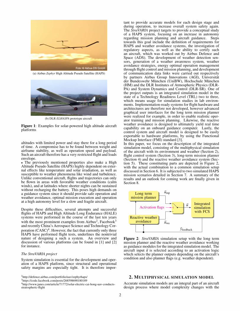
tant to provide accurate models for each design stage andduring operation, to increase overall system safety again.The StraVARIA project targets to provide a conceptual studyof a HAPS system, focusing on an increase in autonomyregarding mission planning and aircraft guidance. Stepstowards this goal include the definition of requirements forHAPS and weather avoidance systems, the investigation ofregulatory aspects, as well as the ability to certify suchan aircraft, which was worked out by Airbus Defence andSpace (ADS). The development of weather detection sen-sors, generation of a weather awareness system, weatheravoidance strategies, energy optimal operation managementthrough flight control and mission planning, and developmentof communication data links were carried out respectivelyby partners Airbus Group Innovations (AGI), Universitätder Bundeswehr München (UniBW), Hochschule München(HM) and the DLR Institutes of Atmospheric Physics (DLR-PA) and System Dynamics and Control (DLR-SR). One ofthe project outputs is an integrated simulation model in thestate of a Technology Readiness Level (TRL) two to three,which means usage for simulation studies in lab environ-ments. Implementation-ready systems for flight hardware andarchitectures are therefore not developed, however advancedgraphical user interfaces for the long term mission plannerwere realized for example, in order to enable realistic oper-ator training and mission planning. Likewise, the reactiveweather avoidance is designed to ultimately yield real timecapability on an onboard guidance computer. Lastly, thecontrol system and aircraft model is designed to be easilyexportable to hardware platforms, by using the FunctionalMockup Interface (FMI) standard [3].In this paper, we focus on the description of the integratedsimulation model, consisting of the multiphysical simulationof the aircraft with its environment and weather (Section 2),flight control system (Section 3), long-term mission planner(Section 4) and the reactive weather avoidance system (Sec-tion 5). These constituting parts are depicted in Figure 2,with the actual combination to a common simulation setupdiscussed in Section 6. It is subjected to two simulated HAPSmission scenarios detailed in Section 7. A summary of theresults and an outlook for coming work are finally given inSection 8.
Long termmission planner
Integratedsimulationwith FCS
Activation flags
~yfeedback
Reactive weatheravoidance
~ump
~uwa
~u
Figure 2: StraVARIA simulation setup with the long termmission planner and the reactive weather avoidance workingas guidance modules for the integrated simulation model. Theaircraft input ~u is selected according to an activation logicwhich selects the planner outputs depending on the aircraft’scondition and also planner flags (e.g. weather dependent).
2. MULTIPHYSICAL SIMULATION MODELAccurate simulation models are an integral part of an aircraftdesign process where model complexity changes with the
2
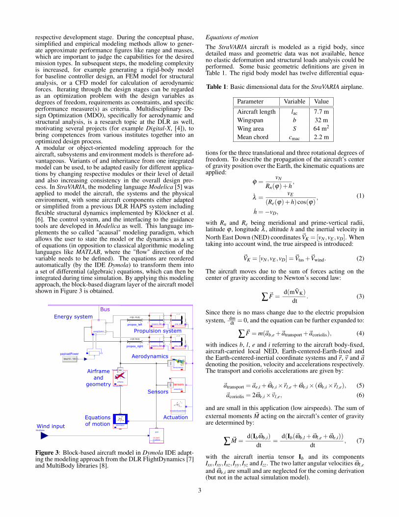
respective development stage. During the conceptual phase,simplified and empirical modeling methods allow to gener-ate approximate performance figures like range and masses,which are important to judge the capabilities for the desiredmission types. In subsequent steps, the modeling complexityis increased, for example generating a rigid-body modelfor baseline controller design, an FEM model for structuralanalysis, or a CFD model for calculation of aerodynamicforces. Iterating through the design stages can be regardedas an optimization problem with the design variables asdegrees of freedom, requirements as constraints, and specificperformance measure(s) as criteria. Multidisciplinary De-sign Optimization (MDO), specifically for aerodynamic andstructural analysis, is a research topic at the DLR as well,motivating several projects (for example Digital-X, [4]), tobring competences from various institutes together into anoptimized design process.A modular or object-oriented modeling approach for theaircraft, subsystems and environment models is therefore ad-vantageous. Variants of and inheritance from one integratedmodel can be used, to be adapted easily for different applica-tions by changing respective modules or their level of detailand also increasing consistency in the overall design pro-cess. In StraVARIA, the modeling language Modelica [5] wasapplied to model the aircraft, the systems and the physicalenvironment, with some aircraft components either adaptedor simplified from a previous DLR HAPS system includingflexible structural dynamics implemented by Klöckner et al.[6]. The control system, and the interfacing to the guidancetools are developed in Modelica as well. This language im-plements the so called "acausal" modeling paradigm, whichallows the user to state the model or the dynamics as a setof equations (in opposition to classical algorithmic modelinglanguages like MATLAB, where the "flow" direction of thevariable needs to be defined). The equations are reorderedautomatically (by the IDE Dymola) to transform them intoa set of differential (algebraic) equations, which can then beintegrated during time simulation. By applying this modelingapproach, the block-based diagram layer of the aircraft modelshown in Figure 3 is obtained.
Figure 3: Block-based aircraft model in Dymola IDE adapt-ing the modeling approach from the DLR FlightDynamics [7]and MultiBody libraries [8].
Equations of motion
The StraVARIA aircraft is modeled as a rigid body, sincedetailed mass and geometric data was not available, henceno elastic deformation and structural loads analysis could beperformed. Some basic geometric definitions are given inTable 1. The rigid body model has twelve differential equa-
Table 1: Basic dimensional data for the StraVARIA airplane.
Parameter Variable Value
Aircraft length lac 7.7 mWingspan b 32 mWing area S 64 m2
Mean chord cmac 2.2 m
tions for the three translational and three rotational degrees offreedom. To describe the propagation of the aircraft’s centerof gravity position over the Earth, the kinematic equations areapplied:
ϕ =vN
Rn(ϕ)+h,
λ =vE
(Re(ϕ)+h)cos(ϕ),
h =−vD,
(1)
with Rn and Re being meridional and prime-vertical radii,latitude ϕ , longitude λ , altitude h and the inertial velocity inNorth East Down (NED) coordinates~VK = [vN ,vE ,vD]. Whentaking into account wind, the true airspeed is introduced:
~VK = [vN ,vE ,vD] =~Vtas +~Vwind. (2)
The aircraft moves due to the sum of forces acting on thecenter of gravity according to Newton’s second law:
∑~F =d(mVK)
dt. (3)
Since there is no mass change due to the electric propulsionsystem, dm
dt = 0, and the equation can be further expanded to:
∑~F = m(~ab,e +~atransport +~acoriolis), (4)
with indices b, l, e and i referring to the aircraft body-fixed,aircraft-carried local NED, Earth-centered-Earth-fixed andthe Earth-centered-inertial coordinate systems and~r, ~v and ~adenoting the position, velocity and accelerations respectively.The transport and coriolis accelerations are given by:
~atransport =~ae,i + ~ωe,i×~rl,e +~ωe,i× (~ωe,i×~rl,e), (5)~acoriolis = 2~ωe,i×~vl,e, (6)
and are small in this application (low airspeeds). The sum ofexternal moments ~M acting on the aircraft’s center of gravityare determined by:
∑ ~M =d(Ib~ωb,i)
dt=
d(Ib(~ωb,l +~ωl,e +~ωe,i))
dt, (7)
with the aircraft inertia tensor Ib and its componentsIxx, Ixy, Ixz, Iyy, Iyz and Izz. The two latter angular velocities ~ωl,eand ~ωe,i are small and are neglected for the coming derivation(but not in the actual simulation model).
3
The sum of forces ~F is comprised of aerodynamic forces(lift and drag), engine thrust, as well as the weight force.The aerodynamic forces and moments are defined in theaerodynamic coordinate system, which is aligned with thevelocity vector of the aircraft relative to the surroundingair. The engine thrust ~T = [XT ,YT ,ZT ] and moments aredefined in the aircraft body fixed system, taking into accountoff center angles for the thrust vector, while the weight isdefined in the local NED system. These forces have to betransformed in body axes and then used in Equation (4). Theforce equations with respect to the l - system are given by:
ub = rbvb−qbwb−gsinΘ+(XA +XT )/m,
vb = −rbub + pbwb +gsinΦcosΘ+(YA +YT )/m,
wb = qbub− pbvb +gcosΦcosΘ+(ZA +ZT )/m,
(8)
with angular rates ~ωb,l = [pb,qb,rb]T and the velocity com-
ponents ~vb,l = [ub,vb,wb]T resolved in the body fixed frame,
obtained from the l frame by rotation around the Euler anglesΦ, Θ and Ψ. When assuming an aircraft symmetric to itsbody x− z plane (Ixy, Iyz = 0), the moment equations can besimplified to:
L = Ixx pb− Ixz (rb + pbqb)+(Izz− Iyy)qbrb,
M = Iyyqb + Ixz(
p2b− r2
b)+(Ixx− Izz) pbrb,
N = Izzrb− Ixz (pb−qbrb)+(Iyy− Ixx) pbqb.
(9)
The aerodynamic forces (XA,YA,ZA) and moments (L,M,N)needed for the solution of (8) and (9), depend onthe dynamic pressure q and the aerodynamic coefficients(Cx,Cy,Cz,CL,CM,CN):
XA = qSCx, YA = qSCy, ZA = qSCz,
L = qSbCL, M = qScCM, N = qSbCN .(10)
The controls are in this case the three control surfaces forailerons δa, elevator δe and rudder δr, as well as the throttlesetting δT . Ailerons are deflected in opposing fashion, whileelevators and engine throttle are equally deflected.
Energy system
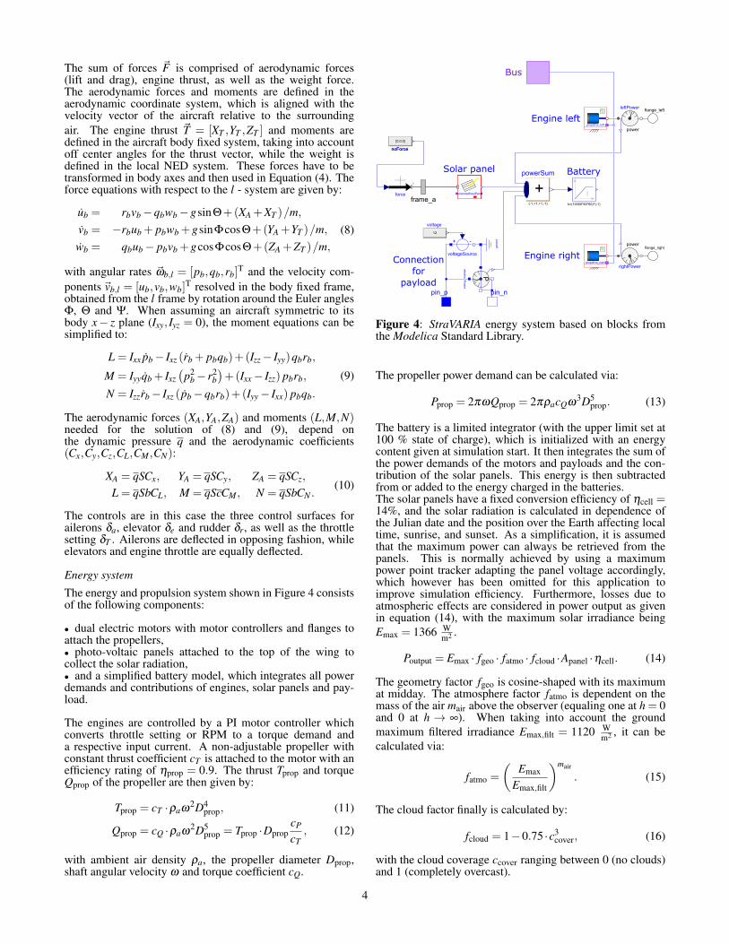
The energy and propulsion system shown in Figure 4 consistsof the following components:
• dual electric motors with motor controllers and flanges toattach the propellers,• photo-voltaic panels attached to the top of the wing tocollect the solar radiation,• and a simplified battery model, which integrates all powerdemands and contributions of engines, solar panels and pay-load.
The engines are controlled by a PI motor controller whichconverts throttle setting or RPM to a torque demand anda respective input current. A non-adjustable propeller withconstant thrust coefficient cT is attached to the motor with anefficiency rating of ηprop = 0.9. The thrust Tprop and torqueQprop of the propeller are then given by:
Tprop = cT ·ρaω2D4
prop, (11)
Qprop = cQ ·ρaω2D5
prop = Tprop ·DpropcP
cT, (12)
with ambient air density ρa, the propeller diameter Dprop,shaft angular velocity ω and torque coefficient cQ.
Figure 4: StraVARIA energy system based on blocks fromthe Modelica Standard Library.
The propeller power demand can be calculated via:
Pprop = 2πωQprop = 2πρacQω3D5
prop. (13)
The battery is a limited integrator (with the upper limit set at100 % state of charge), which is initialized with an energycontent given at simulation start. It then integrates the sum ofthe power demands of the motors and payloads and the con-tribution of the solar panels. This energy is then subtractedfrom or added to the energy charged in the batteries.The solar panels have a fixed conversion efficiency of ηcell =14%, and the solar radiation is calculated in dependence ofthe Julian date and the position over the Earth affecting localtime, sunrise, and sunset. As a simplification, it is assumedthat the maximum power can always be retrieved from thepanels. This is normally achieved by using a maximumpower point tracker adapting the panel voltage accordingly,which however has been omitted for this application toimprove simulation efficiency. Furthermore, losses due toatmospheric effects are considered in power output as givenin equation (14), with the maximum solar irradiance beingEmax = 1366 W
m2 .
Poutput = Emax · fgeo · fatmo · fcloud ·Apanel ·ηcell. (14)
The geometry factor fgeo is cosine-shaped with its maximumat midday. The atmosphere factor fatmo is dependent on themass of the air mair above the observer (equaling one at h = 0and 0 at h → ∞). When taking into account the groundmaximum filtered irradiance Emax,filt = 1120 W
m2 , it can becalculated via:
fatmo =
(Emax
Emax,filt
)mair
. (15)
The cloud factor finally is calculated by:
fcloud = 1−0.75 ·c3cover, (16)
with the cloud coverage ccover ranging between 0 (no clouds)and 1 (completely overcast).
4
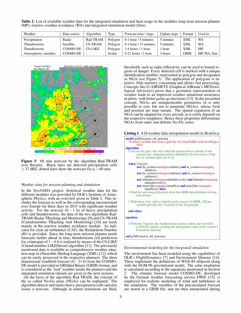
Table 2: List of available weather data for the integrated simulation and their usage in the modules long-term mission planner(MP), reactive weather avoidance (WA) and integrated simulation model (Sim).
Weather Data source Algorithm Type Forecast time / steps Update steps Format Used in
Precipitation Radar Rad-TRAM Polygon 0-1 hour / 5 minutes 5 minutes XML WAThunderstorm Satellite Cb-TRAM Polygon 0-1 hour / 15 minutes 5 minutes XML WAThunderstorm COSMO-DE Cb-LIKE Polygon 1-6 hours / 1 hour 1 hour XML MPAtmospheric variables COSMO-DE - Scalar 0-21 hours / 1 hour 3 hours GRIB MP, WA, Sim
Figure 5: 60 min nowcast by the algorithm Rad-TRAMover Bavaria. Black lines are detected precipitation cells≥ 37 dBZ, dotted lines show the nowcast for t0 +60 min.
Weather data for mission planning and simulation
In the StraVARIA project, historical weather data for thedifferent modules was provided by DLR’s Institute of Atmo-spheric Physics, with an overview given in Table 2. This in-cludes the forecast as well as the corresponding measurementover Europe for three days in 2015 with significant weatheractivity. For the nowcast (0− 1 h) of heavy precipitationcells and thunderstorms, the data of the two algorithms Rad-TRAM (Radar TRacking and Monitoring) [9] and Cb-TRAM(Cumulonimbus TRacking And Monitoring) [10] are used,mainly in the reactive weather avoidance module. As indi-cator for clear air turbulence (CAT), the Richardson-Number(Ri) is provided. Since the long-term mission planner needsforecasts farther ahead in time, thunderstorm cell predictionfor a timespan of 1−6 h is realized by means of the Cb-LIKE(Cumulonimbus LIKElihood) algorithm [11]. The previouslymentioned data is available as comprehensive weather situa-tion map in eXtensible Markup Language (XML) [12], whichcan be easily processed in the respective planners. The threedimensional windfield forecast (0−21 h) from the COSMO-DE model is provided in GRIdded Binary (GRIB) format, andis considered as the "real" weather inside the planners and theintegrated simulation (details are given in the next section).
On the basis of the algorithm Rad-TRAM, the concept ofthe so called No-Go areas (NGAs) can be explained: Thealgorithm detects and tracks heavy precipitation cells and alsoissues a nowcast. Although in nature transitions are fluid,
thresholds such as radar reflectivity can be used to bound re-gions of danger. Every detected cell is marked with a uniqueidentification number, represented as polygon and designatedas NGA (see Figure 5). The application of polygons is in-tuitive, little memory consuming and allows fast processing.Concepts like G-AIRMETS (Graphical AIRman’s METeoro-logical Advisorys) prove that a geometric representation ofweather leads to an improved weather situational awarenessin pilots, with better go/no-go decisions [13]. In the presentedconcept, NGAs are semipermeable geometries (it is onlypossible to exit, but not to penetrate NGAs), whose formand position are time-variant. The spatial expansion of anNGA can be adapted for every aircraft, as it solely depends onthe respective toughness. Hence these properties differentiateNGAs from static and definite No-Fly zones.
Listing 1: 4-D weather data interpolation model in Modelica.model gribExtractor_4d_stravaria
"Extracts variable data from a grib file (for StraVARIA with levelType=150)"
algorithm// Access the grib−file only when the aircraft moves outside of the
current four−dimensional box defined by the 16 vertices of thebox in variables [lat, lon, h, t]
when {initial(),not (la_cosmo>=min(pre(outlats)) and la_cosmo<=max(pre(
outlats))),not (lo_cosmo>=min(pre(outlons)) and lo_cosmo<=max(pre(
outlons))),not (altitude>=min(pre(altitudeLevels)) and altitude<=max(pre(
altitudeLevels))),not (time24h>=min(pre(timePts)) and time24h<=max(pre(
timePts)))} then// Find the enclosing grid points from the GRIB data definition in time
and altitude
// With these, four calls to function grib_nearest of GRIB_API pervariable provides the 16 points of the 4d polytope
end when;
equation
// With the 16 points the Vandermonde matrix is built and solved byLAPACK routines yielding the interpolated value at the current 3D position and time
end gribExtractor_4d_stravaria;
Environmental modeling for the integrated simulation
The environment has been modeled using the capabilities ofDLR’s FlightDynamics [7] and Environment libraries [14].These implement the definitions of WGS-84 ellipsoid alongwith the EGM-96 gravitational model. The solar irradiationis calculated according to the equations mentioned in Section2. The climatic forecast model COSMO-DE, developedby the German weather forecasting service DWD [15], isemployed for realistic modeling of wind and turbulence inthe simulation. The variables of the precalculated forecastare stored in a GRIB file, and are then interpolated during
5
@ h2, t2
@ h1, t2
@ h2, t1
@ h1, t1
uw,r[m
/s]
t [h]0 0.5 1 1.5 2 2.5
5
10
15
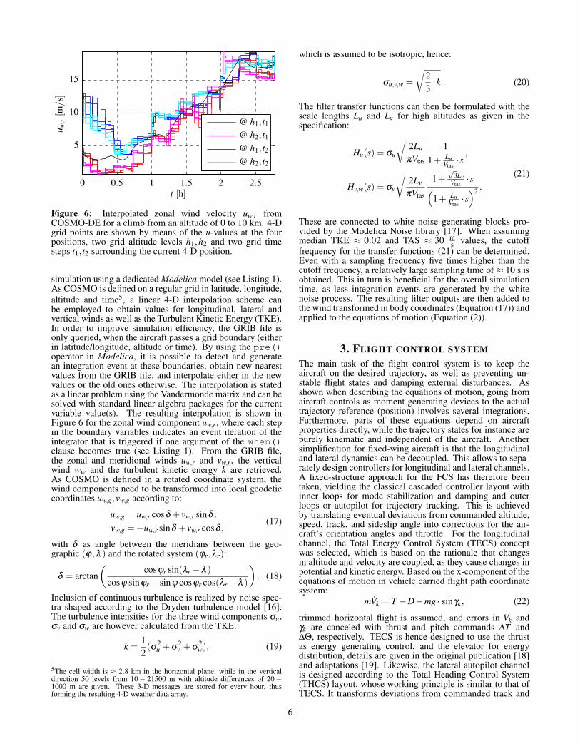
Figure 6: Interpolated zonal wind velocity uw,r fromCOSMO-DE for a climb from an altitude of 0 to 10 km. 4-Dgrid points are shown by means of the u-values at the fourpositions, two grid altitude levels h1,h2 and two grid timesteps t1, t2 surrounding the current 4-D position.
simulation using a dedicated Modelica model (see Listing 1).As COSMO is defined on a regular grid in latitude, longitude,altitude and time5, a linear 4-D interpolation scheme canbe employed to obtain values for longitudinal, lateral andvertical winds as well as the Turbulent Kinetic Energy (TKE).In order to improve simulation efficiency, the GRIB file isonly queried, when the aircraft passes a grid boundary (eitherin latitude/longitude, altitude or time). By using the pre()operator in Modelica, it is possible to detect and generatean integration event at these boundaries, obtain new nearestvalues from the GRIB file, and interpolate either in the newvalues or the old ones otherwise. The interpolation is statedas a linear problem using the Vandermonde matrix and can besolved with standard linear algebra packages for the currentvariable value(s). The resulting interpolation is shown inFigure 6 for the zonal wind component uw,r, where each stepin the boundary variables indicates an event iteration of theintegrator that is triggered if one argument of the when()clause becomes true (see Listing 1). From the GRIB file,the zonal and meridional winds uw,r and vw,r, the verticalwind ww and the turbulent kinetic energy k are retrieved.As COSMO is defined in a rotated coordinate system, thewind components need to be transformed into local geodeticcoordinates uw,g,vw,g according to:
uw,g = uw,r cosδ + vw,r sinδ ,
vw,g =−uw,r sinδ + vw,r cosδ ,(17)
with δ as angle between the meridians between the geo-graphic (ϕ,λ ) and the rotated system (ϕr,λr):
δ = arctan(
cosϕr sin(λr−λ )
cosϕ sinϕr− sinϕ cosϕr cos(λr−λ )
). (18)
Inclusion of continuous turbulence is realized by noise spec-tra shaped according to the Dryden turbulence model [16].The turbulence intensities for the three wind components σu,σv and σw are however calculated from the TKE:
k =12(σ2
u +σ2v +σ
2w), (19)
5The cell width is ≈ 2.8 km in the horizontal plane, while in the verticaldirection 50 levels from 10− 21500 m with altitude differences of 20−1000 m are given. These 3-D messages are stored for every hour, thusforming the resulting 4-D weather data array.
which is assumed to be isotropic, hence:
σu,v,w =
√23·k . (20)
The filter transfer functions can then be formulated with thescale lengths Lu and Lv for high altitudes as given in thespecification:
Hu(s) = σu
√2Lu
πVtas
11+ Lu
Vtas·s,
Hv,w(s) = σv
√2Lv
πVtas
1+√
3LvVtas·s(
1+ LuVtas·s)2 .
(21)
These are connected to white noise generating blocks pro-vided by the Modelica Noise library [17]. When assumingmedian TKE ≈ 0.02 and TAS ≈ 30 m
s values, the cutofffrequency for the transfer functions (21) can be determined.Even with a sampling frequency five times higher than thecutoff frequency, a relatively large sampling time of ≈ 10 s isobtained. This in turn is beneficial for the overall simulationtime, as less integration events are generated by the whitenoise process. The resulting filter outputs are then added tothe wind transformed in body coordinates (Equation (17)) andapplied to the equations of motion (Equation (2)).
3. FLIGHT CONTROL SYSTEMThe main task of the flight control system is to keep theaircraft on the desired trajectory, as well as preventing un-stable flight states and damping external disturbances. Asshown when describing the equations of motion, going fromaircraft controls as moment generating devices to the actualtrajectory reference (position) involves several integrations.Furthermore, parts of these equations depend on aircraftproperties directly, while the trajectory states for instance arepurely kinematic and independent of the aircraft. Anothersimplification for fixed-wing aircraft is that the longitudinaland lateral dynamics can be decoupled. This allows to sepa-rately design controllers for longitudinal and lateral channels.A fixed-structure approach for the FCS has therefore beentaken, yielding the classical cascaded controller layout withinner loops for mode stabilization and damping and outerloops or autopilot for trajectory tracking. This is achievedby translating eventual deviations from commanded altitude,speed, track, and sideslip angle into corrections for the air-craft’s orientation angles and throttle. For the longitudinalchannel, the Total Energy Control System (TECS) conceptwas selected, which is based on the rationale that changesin altitude and velocity are coupled, as they cause changes inpotential and kinetic energy. Based on the x-component of theequations of motion in vehicle carried flight path coordinatesystem:
mVk = T −D−mg · sinγk, (22)
trimmed horizontal flight is assumed, and errors in Vk andγk are canceled with thrust and pitch commands ∆T and∆Θ, respectively. TECS is hence designed to use the thrustas energy generating control, and the elevator for energydistribution, details are given in the original publication [18]and adaptations [19]. Likewise, the lateral autopilot channelis designed according to the Total Heading Control System(THCS) layout, whose working principle is similar to that ofTECS. It transforms deviations from commanded track and
6
Time of day [h]
−∆
V[m
/s]
−∆
h[m
]
Upper power limit
Engine power
Pen
gin
e[k
W]
7 8 9 10 11−2
−1
0
−20
−10
0
0.2
0.4
0.6
0.8
1
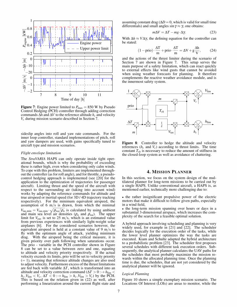
Figure 7: Engine power limited to Pmax = 850 W by PseudoControl Hedging (PCH) controller through adding correctioncommands ∆h and ∆V to the reference altitude hc and velocityVc during mission scenario described in Section 7.
sideslip angles into roll and yaw rate commands. For theinner loop controller, standard implementations of pitch, rolland yaw dampers are used, with gains specifically tuned toaircraft type and mission scenarios.
Flight envelope limitation
The StraVARIA HAPS can only operate inside tight oper-ational bounds, which is why the probability of exceedingthese is rather high, even when considering only calm winds.To cope with this problem, limiters are implemented through-out the controller (as for roll angle), and for throttle, a pseudo-control hedging approach is implemented (see [20] for theapplication to the optimization of trajectories for passengeraircraft). Limiting thrust and the speed of the aircraft withrespect to the surrounding air (taking into account wind)works by adapting the reference commands for altitude andtrue airspeed or inertial speed (for 3D / 4D trajectory trackingrespectively). For the minimum equivalent airspeed, theassumption of 6 m/s is drawn, from which the minimalVtas,min = Veas,min ·
√ρisa/ρa is calculated by using ambient
and main sea level air densities (ρa and ρisa). The upperlimit for Veas is set to 25 m/s, which is an estimated valuefrom previous experiences with similarly light-weight solarairplanes [6]. For the considered scenarios however, theequivalent airspeed is held at a constant value of 9 m/s tofly with the optimum angle of attack, yielding minimumdrag. With the airspeed being the critical measure, it isgiven priority over path following when saturations occur.The prio - variable in the PCH controller shown in Figure8 can be set to a value between zero and one, equatingto altitude and velocity priority respectively. If the actualvelocity exceeds its limits, prio will be set to velocity priority(= 1), meaning that reference altitude changes are also usedto adjust velocity. Furthermore excess of the thrust limitationsare fed back with variable ∆T , which is transformed into analtitude and velocity correction command (∆T > 0 :→ hlim <hc,Vlim < Vc, ∆T < 0 :→ hlim > hc,Vlim > Vc) by the PCH.This is based on the relation given in (22) as well, afterperforming a linearization around the current flight state and
assuming constant drag (∆D= 0, which is valid for small timedifferentials) and small angles sinγ ≈ γ , one obtains:
m∆V = ∆T −mg ·∆γ. (23)
With ∆h ≈ V ∆γ , the defining equation for the controller canbe stated:
(1−prio) · ∆Tm
+prio · ∆Tm
= ∆V+g∆hV
, (24)
and the actions of the thrust limiter during the scenario ofSection 7 are shown in Figure 7. This setup serves themain purpose of a safety limitation, which can react quicklyto external effects like wind gusts that cannot be avoidedwhen using weather forecasts for planning. It thereforecomplements the reactive weather avoidance module, and isthe innermost safety system.
1g +
−
−+ +−
Tvh
∆T
m Vtas hc
hlim
1
prioVc
Vlim
m
Figure 8: Controller to hedge the altitude and velocityreferences (hc and Vc) according to thrust limits. The timeconstant Tvh is necessary to reduce the amount of stiffness inthe closed-loop system as well as avoidance of chattering.
4. MISSION PLANNERIn this section, we focus on the system design of the mul-tilateral planner for long-term missions to be carried out bya single HAPS. Unlike conventional aircraft, a HAPS is, asmentioned earlier, technically more challenging due to:
• the rather insignificant propulsive power of the electricmotors that make it difficult to follow given paths, especiallyin a wind field,• the long-term mission spanning over hours or days in asubstantial 3-dimensional airspace, which increases the com-plexity of the search for a feasible optimal solution.
A hybrid approach involving scheduling and planning is verywidely used, for example in [21] and [22]. The schedulerdecides logically for the execution order of the tasks, whilethe lower level planner optimizes the way the tasks areexecuted. Kiam and Schulte adapted the hybrid architectureto a probabilistic problem [23]. The scheduler first proposesseveral schedules with different task execution orders. Sub-sequently, the analytical planner calculates the UAV paths forthe schedules that most probably maximize the mission re-wards within the allocated planning time. Once the planningtime is due, the schedules, that are not yet considered by theanalytical planner will be ignored.
Logical Planning
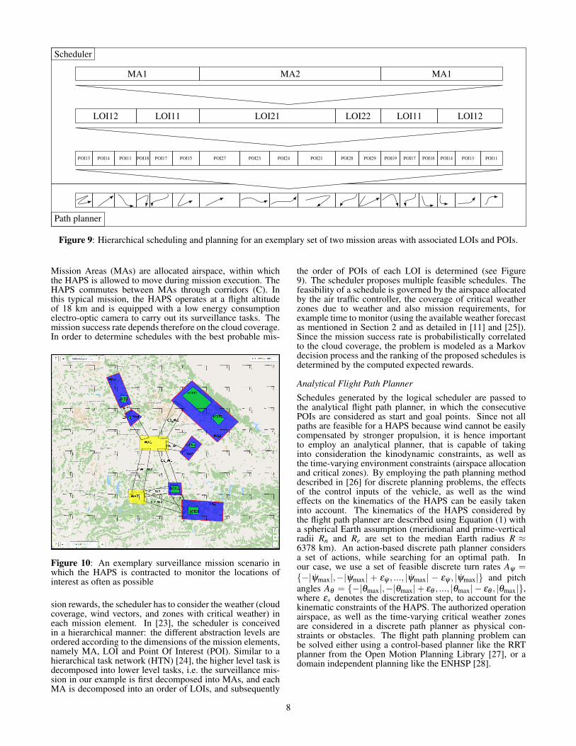
Figure 10 shows a simple exemplary mission scenario. TheLocations Of Interest (LOIs) are areas to monitor, while the
7
POI13 POI14 POI11 POI18 POI17 POI15 POI27 POI23 POI24 POI21 POI28 POI29 POI19 POI17 POI18 POI14 POI13 POI11
LOI12 LOI11 LOI21 LOI22 LOI11 LOI12
MA1 MA2 MA1
Scheduler
Path planner
Figure 9: Hierarchical scheduling and planning for an exemplary set of two mission areas with associated LOIs and POIs.
Mission Areas (MAs) are allocated airspace, within whichthe HAPS is allowed to move during mission execution. TheHAPS commutes between MAs through corridors (C). Inthis typical mission, the HAPS operates at a flight altitudeof 18 km and is equipped with a low energy consumptionelectro-optic camera to carry out its surveillance tasks. Themission success rate depends therefore on the cloud coverage.In order to determine schedules with the best probable mis-
Figure 10: An exemplary surveillance mission scenario inwhich the HAPS is contracted to monitor the locations ofinterest as often as possible
sion rewards, the scheduler has to consider the weather (cloudcoverage, wind vectors, and zones with critical weather) ineach mission element. In [23], the scheduler is conceivedin a hierarchical manner: the different abstraction levels areordered according to the dimensions of the mission elements,namely MA, LOI and Point Of Interest (POI). Similar to ahierarchical task network (HTN) [24], the higher level task isdecomposed into lower level tasks, i.e. the surveillance mis-sion in our example is first decomposed into MAs, and eachMA is decomposed into an order of LOIs, and subsequently
the order of POIs of each LOI is determined (see Figure9). The scheduler proposes multiple feasible schedules. Thefeasibility of a schedule is governed by the airspace allocatedby the air traffic controller, the coverage of critical weatherzones due to weather and also mission requirements, forexample time to monitor (using the available weather forecastas mentioned in Section 2 and as detailed in [11] and [25]).Since the mission success rate is probabilistically correlatedto the cloud coverage, the problem is modeled as a Markovdecision process and the ranking of the proposed schedules isdetermined by the computed expected rewards.
Analytical Flight Path Planner
Schedules generated by the logical scheduler are passed tothe analytical flight path planner, in which the consecutivePOIs are considered as start and goal points. Since not allpaths are feasible for a HAPS because wind cannot be easilycompensated by stronger propulsion, it is hence importantto employ an analytical planner, that is capable of takinginto consideration the kinodynamic constraints, as well asthe time-varying environment constraints (airspace allocationand critical zones). By employing the path planning methoddescribed in [26] for discrete planning problems, the effectsof the control inputs of the vehicle, as well as the windeffects on the kinematics of the HAPS can be easily takeninto account. The kinematics of the HAPS considered bythe flight path planner are described using Equation (1) witha spherical Earth assumption (meridional and prime-verticalradii Rn and Re are set to the median Earth radius R ≈6378 km). An action-based discrete path planner considersa set of actions, while searching for an optimal path. Inour case, we use a set of feasible discrete turn rates Aψ ={−|ψmax|,−|ψmax| + εψ , ..., |ψmax| − εψ , |ψmax|} and pitchangles Aθ = {−|θmax|,−|θmax|+ εθ , ..., |θmax| − εθ , |θmax|},where ε∗ denotes the discretization step, to account for thekinematic constraints of the HAPS. The authorized operationairspace, as well as the time-varying critical weather zonesare considered in a discrete path planner as physical con-straints or obstacles. The flight path planning problem canbe solved either using a control-based planner like the RRTplanner from the Open Motion Planning Library [27], or adomain independent planning like the ENHSP [28].
8
Selection of the Best Plan
As mentioned above, the scheduler computes several feasibleschedules and ranks them based on the expected missionreward. The ranking is however probabilistic and inaccuratedue to the innate probabilistic property of the weather fore-casts and the approximated time needed for each higher levelsubtask in the hierarchical scheduler. The latter contributesto the inaccuracy of the computed reward and cost of eachscheduler. More accurate rewards and costs can be computedwith the analytical path planner. Therefore, the final rankingcan only be determined at the lowest abstraction level ofthe hierarchical scheduler/planner. Although considering theforecasted weather conditions and the flight kinematics com-plicating the planning, the selected plan is of better qualityin the sense that the feasibility and reward are optimized,which in turn results in less frequent replanning. Replanningoccurs only, if the weather conditions differ too much fromthe forecast, or if the mission requirements are altered.
5. WEATHER AVOIDANCE MODULEThe University of Applied Sciences Munich (HM) works ona module for HAPS that automatically generates flight pathsto overcome adverse weather conditions. The objective isto increase their automation and safety levels, and by thismeans improve mission fulfillment. In civil aviation, approx-imately 20% of the accidents are related to adverse weather[29]. Fragile aircraft like HAPS are especially at risk, andtherefore require a particularly provident avoidance in certainphases of the flight, i.e. ascent and descent through weatheractive troposphere [30]. The focus lies on the handling ofthunderstorm, turbulence and wind for a short-term span upto one hour.
Operation Area
0.5 1 1.5 2 2.5
·105
0
0.5
1
1.5
2
·105
East [m]
Nor
th[m
]
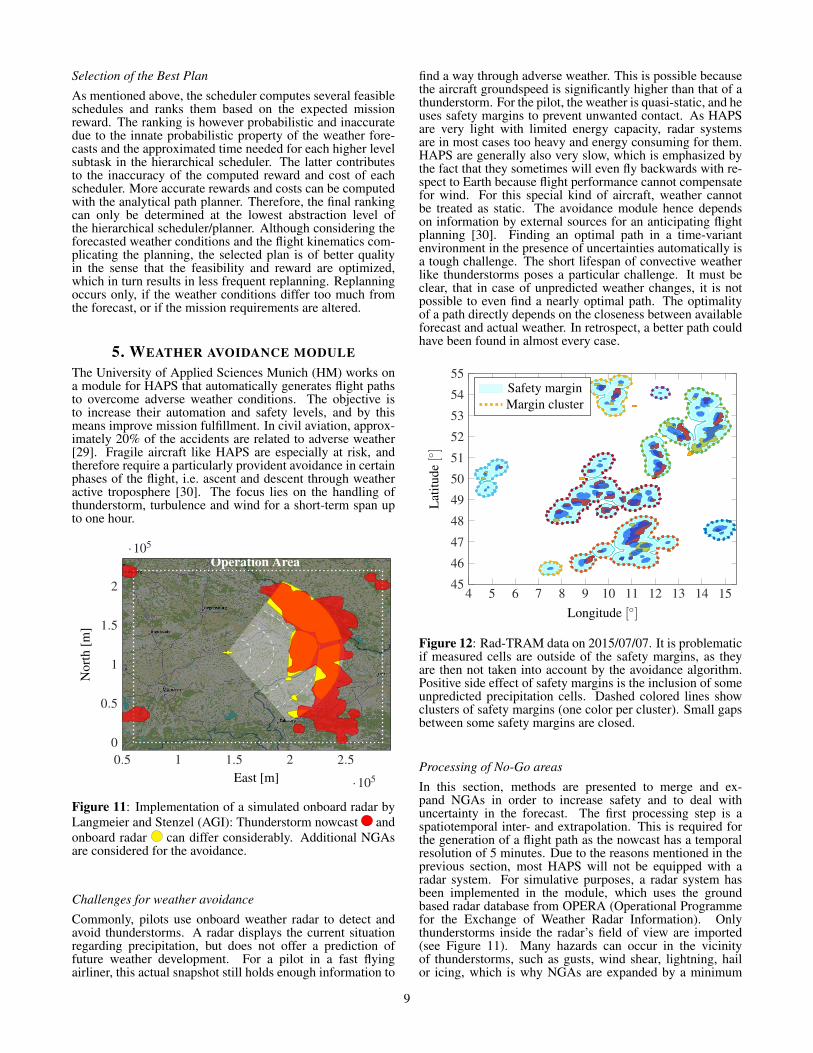
Figure 11: Implementation of a simulated onboard radar byLangmeier and Stenzel (AGI): Thunderstorm nowcast andonboard radar can differ considerably. Additional NGAsare considered for the avoidance.
Challenges for weather avoidance
Commonly, pilots use onboard weather radar to detect andavoid thunderstorms. A radar displays the current situationregarding precipitation, but does not offer a prediction offuture weather development. For a pilot in a fast flyingairliner, this actual snapshot still holds enough information to
find a way through adverse weather. This is possible becausethe aircraft groundspeed is significantly higher than that of athunderstorm. For the pilot, the weather is quasi-static, and heuses safety margins to prevent unwanted contact. As HAPSare very light with limited energy capacity, radar systemsare in most cases too heavy and energy consuming for them.HAPS are generally also very slow, which is emphasized bythe fact that they sometimes will even fly backwards with re-spect to Earth because flight performance cannot compensatefor wind. For this special kind of aircraft, weather cannotbe treated as static. The avoidance module hence dependson information by external sources for an anticipating flightplanning [30]. Finding an optimal path in a time-variantenvironment in the presence of uncertainties automatically isa tough challenge. The short lifespan of convective weatherlike thunderstorms poses a particular challenge. It must beclear, that in case of unpredicted weather changes, it is notpossible to even find a nearly optimal path. The optimalityof a path directly depends on the closeness between availableforecast and actual weather. In retrospect, a better path couldhave been found in almost every case.
4 5 6 7 8 9 10 11 12 13 14 1545
46
47
48
49
50
51
52
53
54
55
Longitude [◦]
Lat
itude
[◦]
Safety marginMargin cluster
Figure 12: Rad-TRAM data on 2015/07/07. It is problematicif measured cells are outside of the safety margins, as theyare then not taken into account by the avoidance algorithm.Positive side effect of safety margins is the inclusion of someunpredicted precipitation cells. Dashed colored lines showclusters of safety margins (one color per cluster). Small gapsbetween some safety margins are closed.
Processing of No-Go areas
In this section, methods are presented to merge and ex-pand NGAs in order to increase safety and to deal withuncertainty in the forecast. The first processing step is aspatiotemporal inter- and extrapolation. This is required forthe generation of a flight path as the nowcast has a temporalresolution of 5 minutes. Due to the reasons mentioned in theprevious section, most HAPS will not be equipped with aradar system. For simulative purposes, a radar system hasbeen implemented in the module, which uses the groundbased radar database from OPERA (Operational Programmefor the Exchange of Weather Radar Information). Onlythunderstorms inside the radar’s field of view are imported(see Figure 11). Many hazards can occur in the vicinityof thunderstorms, such as gusts, wind shear, lightning, hailor icing, which is why NGAs are expanded by a minimum
9
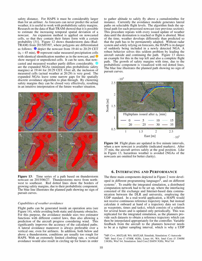
safety distance. For HAPS it must be considerably largerthan for an airliner. As forecasts can never predict the actualweather, it is useful to work with probabilistic safety margins.Research on the data of Rad-TRAM showed that it is possibleto estimate the increasing temporal spatial deviation of anowcast. An expansion method is applied on nowcastedcells, so that they contain their future form with a certainprobability [31]. Figure 12 shows thunderstorm data (Rad-TRAM) from 2015/07/07, where polygons are differentiatedas follows: depict the nowcast from 19:44 to 20:29 CET(t0 +45 min), represent radar measured precipitation cellswith identical identification number as in the nowcast, andshow merged or unpredicted cells. It can be seen, that now-casted and measured weather partly differs considerably.are the expanded NGAs (minimum plus probabilistic safetymargins) at 19:44 for 20:29 CET. Over all, the inclusion ofmeasured cells (actual weather at 20:29) is very good. Theexpanded NGAs leave some narrow gaps for the spatiallydiscrete avoidance algorithm to plan through. By clusteringsafety margins they can be closed very effectively, resultingin an intuitive interpretation of the future weather situation.
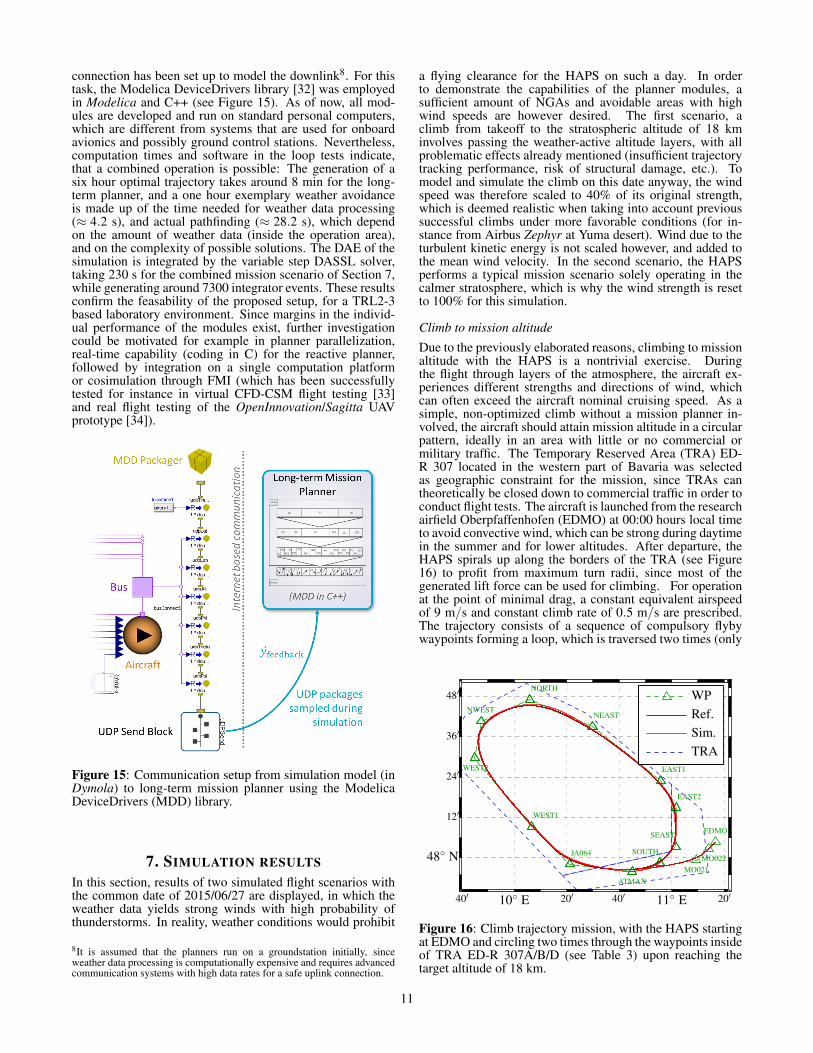
Figure 13: Time series of a path based on thunderstormnowcast on 2015/06/27. Thunderstorms move from north-west to southeast. Red dotted lines show the borders ofgrowing safety margins, due to their probabilistic component.The blue line illustrates the planned path showing no sign ofpursuit curves.
Capabilities of weather avoidance
Flight paths can be generated inside an operation area (seeFigure 14), while avoiding both static and dynamic obstacles.For this purpose, the avoidance module uses two estimatorfunctions with different control laws, thus also allowing aprediction of the aircraft progress considering wind. Thissignificantly improves the accuracy of the calculated paths.A lateral avoidance maneuver is always preferable over avertical one, even for airliners. In addition, both below andabove a thunderstorm, conditions are usually too rough forHAPS. With an extremely limited climbing rate, a verticalavoidance would also result in circling up for hours in order
to gather altitude to safely fly above a cumulonimbus forinstance. Currently the avoidance module generates lateralpaths on selectable flight levels. The algorithm finds the op-timal path for each processed nowcast (see previous section).This procedure repeats with every issued update of weatherdata until the destination is reached or flight is aborted. Mostof the time, weather develops differently than predicted sothat the path has to be permanently adapted. Without radarsystem and solely relying on forecasts, the HAPS is in dangerof suddenly being included in a newly detected NGA. Arobust behavior solves this seldom problem by leading theaircraft outside and continuing the path. Figure 13 showsan example for this in the top left and also a complete flightpath. The growth of safety margins with time, due to theprobabilistic component is visualized with red dotted lines.The blue line illustrates the planned path showing no sign ofpursuit curves.
Operation Area
Start
Goal
1 1.5 2 2.5
·105
0.5
1
1.5
2
2.5·105
East [m]
Nor
th[m
]
0 5 10 1520 25 30 35
Flightplans issued after t0 [min]:
Figure 14: Flight plans are updated in five minute intervals,when a new nowcast is available (indicated markers). After37 min, the aircraft arrives safely at the goal position. Likein Figure 13, hazardous weather is avoided (NGAs of thenowcasts are omitted for better clarity).
6. INTERFACING AND PERFORMANCEThe three main components depicted in Figure 2 were devel-oped in different programming languages6, and on differentsystems7. To enable the integrated simulation, a distributedcomputation network had to be set up, where the interfacingconsisted of file exchange and Internet-based data commu-nication between the DLR and university, employing theUDP standard. In a real-world application, a HAPS wouldnot receive continuous reference trajectory input, but insteadcalculate it onboard at hand of a trajectory data set (suchas waypoints, times and tasks), which consists of a solutionfor several hours and is updated only periodically. This wasreplicated for the integrated simulation, as the planners pro-vide such datasets to obtain a reference trajectory which canthen be interpolated appropriately for the controller. Variablefeedback from the aircraft to the planners however needsto be at a tighter sampling interval, which is why a UDP
6MP: C++, MATLAB, WA: MATLAB, Simulink, Simulation: C-Autocode7MP: Intel Core i7 6700K 4GHz, Linux 64, WA: Intel Core i5 3360M2.8GHz, Win7 64, Simulation: Intel Core2 E6850 3GHz, Win7 64
10
connection has been set up to model the downlink8. For thistask, the Modelica DeviceDrivers library [32] was employedin Modelica and C++ (see Figure 15). As of now, all mod-ules are developed and run on standard personal computers,which are different from systems that are used for onboardavionics and possibly ground control stations. Nevertheless,computation times and software in the loop tests indicate,that a combined operation is possible: The generation of asix hour optimal trajectory takes around 8 min for the long-term planner, and a one hour exemplary weather avoidanceis made up of the time needed for weather data processing(≈ 4.2 s), and actual pathfinding (≈ 28.2 s), which dependon the amount of weather data (inside the operation area),and on the complexity of possible solutions. The DAE of thesimulation is integrated by the variable step DASSL solver,taking 230 s for the combined mission scenario of Section 7,while generating around 7300 integrator events. These resultsconfirm the feasability of the proposed setup, for a TRL2-3based laboratory environment. Since margins in the individ-ual performance of the modules exist, further investigationcould be motivated for example in planner parallelization,real-time capability (coding in C) for the reactive planner,followed by integration on a single computation platformor cosimulation through FMI (which has been successfullytested for instance in virtual CFD-CSM flight testing [33]and real flight testing of the OpenInnovation/Sagitta UAVprototype [34]).
Figure 15: Communication setup from simulation model (inDymola) to long-term mission planner using the ModelicaDeviceDrivers (MDD) library.
7. SIMULATION RESULTSIn this section, results of two simulated flight scenarios withthe common date of 2015/06/27 are displayed, in which theweather data yields strong winds with high probability ofthunderstorms. In reality, weather conditions would prohibit
8It is assumed that the planners run on a groundstation initially, sinceweather data processing is computationally expensive and requires advancedcommunication systems with high data rates for a safe uplink connection.
a flying clearance for the HAPS on such a day. In orderto demonstrate the capabilities of the planner modules, asufficient amount of NGAs and avoidable areas with highwind speeds are however desired. The first scenario, aclimb from takeoff to the stratospheric altitude of 18 kminvolves passing the weather-active altitude layers, with allproblematic effects already mentioned (insufficient trajectorytracking performance, risk of structural damage, etc.). Tomodel and simulate the climb on this date anyway, the windspeed was therefore scaled to 40% of its original strength,which is deemed realistic when taking into account previoussuccessful climbs under more favorable conditions (for in-stance from Airbus Zephyr at Yuma desert). Wind due to theturbulent kinetic energy is not scaled however, and added tothe mean wind velocity. In the second scenario, the HAPSperforms a typical mission scenario solely operating in thecalmer stratosphere, which is why the wind strength is resetto 100% for this simulation.
Climb to mission altitude
Due to the previously elaborated reasons, climbing to missionaltitude with the HAPS is a nontrivial exercise. Duringthe flight through layers of the atmosphere, the aircraft ex-periences different strengths and directions of wind, whichcan often exceed the aircraft nominal cruising speed. As asimple, non-optimized climb without a mission planner in-volved, the aircraft should attain mission altitude in a circularpattern, ideally in an area with little or no commercial ormilitary traffic. The Temporary Reserved Area (TRA) ED-R 307 located in the western part of Bavaria was selectedas geographic constraint for the mission, since TRAs cantheoretically be closed down to commercial traffic in order toconduct flight tests. The aircraft is launched from the researchairfield Oberpfaffenhofen (EDMO) at 00:00 hours local timeto avoid convective wind, which can be strong during daytimein the summer and for lower altitudes. After departure, theHAPS spirals up along the borders of the TRA (see Figure16) to profit from maximum turn radii, since most of thegenerated lift force can be used for climbing. For operationat the point of minimal drag, a constant equivalent airspeedof 9 m/s and constant climb rate of 0.5 m/s are prescribed.The trajectory consists of a sequence of compulsory flybywaypoints forming a loop, which is traversed two times (only
48
′
36′
24′
12′
20′
40′
20′
40′
TRA
Sim.
Ref.
WP
48◦
N
11◦
E10◦
E
SOUTH
SEAST
EAST2
EAST1
NEAST
NORTH
NWEST
WEST2
WEST1
JA064
ATMAX
MO021
MO022
EDMO
Figure 16: Climb trajectory mission, with the HAPS startingat EDMO and circling two times through the waypoints insideof TRA ED-R 307A/B/D (see Table 3) upon reaching thetarget altitude of 18 km.
11
Time of day [h]
VgroundVeasVtasVtas,ref
V[m
/s]
∆y[k
m]
h[k
m]
χ[◦]
γ[◦]
0 2 4 6 8 10 12
5
10
15
20
25
−1
0
5
10
15
−180
−90
0
90
180
1
2
3
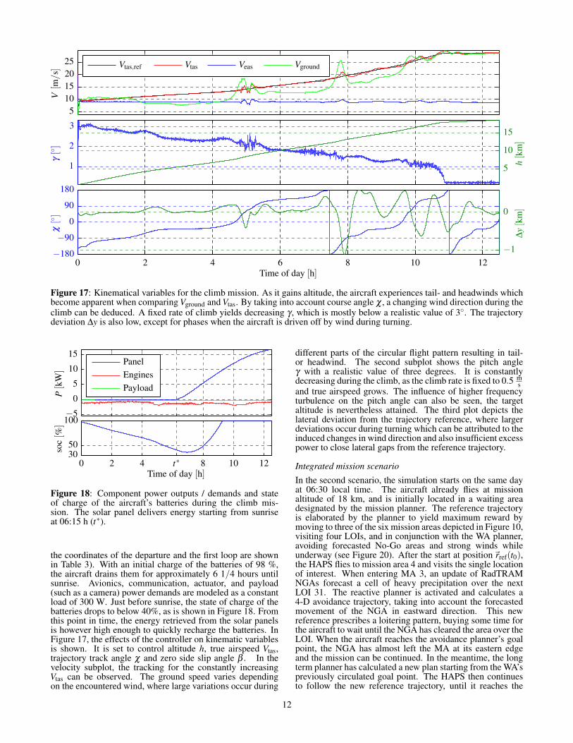
Figure 17: Kinematical variables for the climb mission. As it gains altitude, the aircraft experiences tail- and headwinds whichbecome apparent when comparing Vground and Vtas. By taking into account course angle χ , a changing wind direction during theclimb can be deduced. A fixed rate of climb yields decreasing γ , which is mostly below a realistic value of 3◦. The trajectorydeviation ∆y is also low, except for phases when the aircraft is driven off by wind during turning.
Time of day [h]
soc[%
]
Payload
Engines
Panel
P[k
W]
0 2 4 t∗ 8 10 12
3050
100−5
0
5
10
15
Figure 18: Component power outputs / demands and stateof charge of the aircraft’s batteries during the climb mis-sion. The solar panel delivers energy starting from sunriseat 06:15 h (t∗).
the coordinates of the departure and the first loop are shownin Table 3). With an initial charge of the batteries of 98 %,the aircraft drains them for approximately 6 1/4 hours untilsunrise. Avionics, communication, actuator, and payload(such as a camera) power demands are modeled as a constantload of 300 W. Just before sunrise, the state of charge of thebatteries drops to below 40%, as is shown in Figure 18. Fromthis point in time, the energy retrieved from the solar panelsis however high enough to quickly recharge the batteries. InFigure 17, the effects of the controller on kinematic variablesis shown. It is set to control altitude h, true airspeed Vtas,trajectory track angle χ and zero side slip angle β . In thevelocity subplot, the tracking for the constantly increasingVtas can be observed. The ground speed varies dependingon the encountered wind, where large variations occur during
different parts of the circular flight pattern resulting in tail-or headwind. The second subplot shows the pitch angleγ with a realistic value of three degrees. It is constantlydecreasing during the climb, as the climb rate is fixed to 0.5 m
sand true airspeed grows. The influence of higher frequencyturbulence on the pitch angle can also be seen, the targetaltitude is nevertheless attained. The third plot depicts thelateral deviation from the trajectory reference, where largerdeviations occur during turning which can be attributed to theinduced changes in wind direction and also insufficient excesspower to close lateral gaps from the reference trajectory.
Integrated mission scenario
In the second scenario, the simulation starts on the same dayat 06:30 local time. The aircraft already flies at missionaltitude of 18 km, and is initially located in a waiting areadesignated by the mission planner. The reference trajectoryis elaborated by the planner to yield maximum reward bymoving to three of the six mission areas depicted in Figure 10,visiting four LOIs, and in conjunction with the WA planner,avoiding forecasted No-Go areas and strong winds whileunderway (see Figure 20). After the start at position~rref(t0),the HAPS flies to mission area 4 and visits the single locationof interest. When entering MA 3, an update of RadTRAMNGAs forecast a cell of heavy precipitation over the nextLOI 31. The reactive planner is activated and calculates a4-D avoidance trajectory, taking into account the forecastedmovement of the NGA in eastward direction. This newreference prescribes a loitering pattern, buying some time forthe aircraft to wait until the NGA has cleared the area over theLOI. When the aircraft reaches the avoidance planner’s goalpoint, the NGA has almost left the MA at its eastern edgeand the mission can be continued. In the meantime, the longterm planner has calculated a new plan starting from the WA’spreviously circulated goal point. The HAPS then continuesto follow the new reference trajectory, until it reaches the
12
Time of day [h]
Simulation
Reference
χ[◦]
VgroundVeasVtasVtas,ref
V[m
/s]
∆t[s]
∆y[k
m]
t0 7 8 t1 t2 9 t3 10 11 t f
−360
0
360
720
10
20
30
0
10
20
−0.4
−0.2
0
0.2
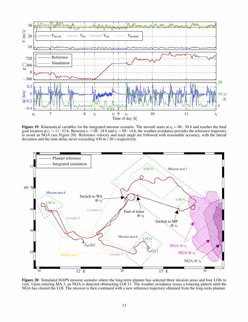
Figure 19: Kinematical variables for the integrated mission scenario. The aircraft starts at t0 = 06 : 30 h and reaches the finalgoal location at t f = 11 : 53 h. Between t1 = 08 : 18 h and t3 = 09 : 14 h, the weather avoidance provides the reference trajectoryto avoid an NGA (see Figure 20). Reference velocity and track angle are followed with reasonable accuracy, with the lateraldeviation and the time delay never exceeding 430 m / 20 s respectively.
12′
48′
36′
24′
30′30′30′
Integrated simulation
Planner reference
49◦ N
13◦ E12◦ E
~rref(t f )
~rref(t0)
End of loiter@ t2
Switch to WA@ t1
Switch to MP@ t3
LOI 61
LOI 41
LOI 32
LOI 31
Waiting area 1
NGA @ t3
Corridor 5
Corridor 4
Corridor 3
Mission area 6
Mission area 4
Mission area 3
NGA @ t2
NGA @ t1
Figure 20: Simulated HAPS mission scenario where the long-term planner has selected three mission areas and four LOIs tovisit. Upon entering MA 3, an NGA is detected obstructing LOI 31. The weather avoidance issues a loitering pattern until theNGA has cleared the LOI. The mission is then continued with a new reference trajectory obtained from the long-term planner.
13
goal point at final position~rref(t f ). In Figure 19, the velocitytracking is shown. As the planners incorporate wind incalculation of estimated arrival times at prescribed missionareas and LOIs, the 4-D reference trajectory is calculated withrespect to the constraint of holding the equivalent airspeedclose to the optimum value of 9 m/s. This in turn generatesthe desired ground track angle χ as input to the flight controlsystem (second subplot of Figure 19). During the loiter phase,stepwise changes are visible, which are due to the solutionprocess in the reactive planner, treating the avoidance as alinear problem. As well, the low air density and the slowdynamic behaviour of the aircraft induce some lag and devi-ation in the track angle during turning. These lags also leadto deviations in the lateral distance to the reference trajectoryand also in time, as shown in the third subplot of Figure 19.Maximum values of ∆ymax ≈ 430 m and ∆tmax ≈ 20 s aredeemed acceptable for this aircraft type and application.
Table 3: Waypoint data for the first loop of the climb missionshown in Figure 16, where the second loop starts at waypointATMAX.
Name Coord. Track Altitude TAS
EDMO N 48 04.88’E 011 16.98’
222◦ 610 m 9.26 ms
MO022 N 48 02.69’E 011 14.00’
222◦ 875.69 m 9.39 ms
MO021 N 47 59.31’E 011 09.40’
258◦ 1322.28 m 9.59 ms
ATMAX N 47 55.78’E 010 45.00’
278◦ 2878.62 m 10.38 ms
JA064 N 47 58.04’E 010 21.21’
319◦ 4267.78 m 11.16 ms
WEST1 N 48 09.27’E 010 06.73’
325◦ 5460.84 m 11.90 ms
WEST2 N 48 29.65’E 009 44.97’
9◦ 7309.74 m 13.20 ms
NWEST N 48 40.60’E 009 47.45’
62◦ 8069.78 m 13.80 ms
NORTH N 48 47.02’E 010 05.90’
117◦ 8971.26 m 14.56 ms
NEAST N 48 38.97’E 010 29.80’
133◦ 10063.53 m 15.56 ms
EAST1 N 48 22.92’E 010 55.83’
154◦ 11408.17 m 17.05 ms
EAST2 N 48 14.82’E 011 01.68’
180◦ 11887.57 m 17.70 ms
SEAST N 48 03.37’E 011 01.60’
220◦ 12472.96 m 18.54 ms
SOUTH N 47 58.43’E 010 55.44’
222◦ 12790.75 m 19.01 ms
8. SUMMARY AND OUTLOOKIn this work, the key components for a multiphysical simula-tion of a HAPS platform and typical missions are presented,consisting of a long-term mission planner, a reactive weatheravoidance, a flight control system, and a detailed simulationmodel including environmental effects. Regarding the plan-ning modules, mission plans and avoidance trajectories canbe generated, which on the one hand respect the dynamicallimits of the aircraft by avoiding adverse weather conditions,and on the other hand ensure an optimized operation withrespect to the mission goals. The flight control systemreceives these trajectories as reference input, whose architec-ture is based on a combination of the total energy and totalheading control approaches with standard cascaded innerloop controllers. As innermost safety layer, the controllerfurthermore features basic limitations for several variables,
and a pseudo-control hedging controller to consider powerlimitations of the electric motors by modifying referencetrajectory signals. The simulation makes heavy use of theadvanced abilities of the Modelica modeling language andintroduces detailed models of the environmental conditionsincluding 4-D weather, the aircraft systems and dynamics.Two scenarios were investigated, with the first one being anon-optimized climb to a stratospheric target altitude. Byusing realistic wind conditions, the mission could be com-pleted. The second scenario implements a reference missioncalculated by the long-term mission planner, involving thevisit of several mission areas and location of interest in anoptimal way, according to several constraints. During theflight, the reactive weather avoidance module successfullyredirects the aircraft to avoid a previously unknown No-Goarea emerging over one of the fly-over locations of interest.After the avoidance, the trajectory reference is switched backto a newly calculated solution of the long-term planner. Theaircraft successfully completes this mission, with only minordeviations in time and lateral position tracking.Directions for further research with respect to modeling in-clude the consideration of structural flexibility in the equa-tions of motion, enabling studies on stress and fatigue of theairframe, which would be highly relevant for this application.In combination, controller design and synthesis could also besubject for further studies, for example to safeguard flight andloads envelopes and ensure controller robustness to externaldisturbances (such as wind). Datalinks and interfacing couldbe further adapted to meet operational standards, and plannerscould benefit from performance gains by parallelization andintegration on a common platform. All in all, the feasabilityof a HAPS platform with increased autonomy is supportedby the results of this study and motivates further researchtowards applications for future HAPS or HALE systems.
ACKNOWLEDGMENTSThe authors wish to thank the Bayerische Staatsministeriumfür Wirtschaft, Medien, Energie und Technologie for fundingthe project StraVARIA. Thanks also go to Andreas Langmeierand Erwin Stenzel (Airbus Group Innovations) for provisionof the radar simulation and help with the OPERA data,Andreas Klöckner (DLR-PD) for the work performed inmanagement of the workpackage and modeling, BernhardThiele (Modelon AB) for help with the integration of the UDPconnection in the simulation, as well as Martin Köhler (DLR-PA) for the support concerning weather data processing.
REFERENCES[1] X. Zhu, Z. Guo, and Z. Hou, “Solar-powered air-
planes: A historical perspective and future challenges,”Progress in Aerospace Sciences, vol. 71, pp. 36–53,2014.
[2] A. Klöckner, “Behavior trees for mission managementof high-altitude pseudo-satellites,” Ph.D. dissertation,Universität der Bundeswehr München, August 2016.[Online]. Available: http://elib.dlr.de/109469/
[3] Functional Mock-up Interface for Model Exchange andCo-Simulation, Version 2.0, Modelica Association, July2014.
[4] N. Kroll, M. Abu-Zurayk, D. Dimitrov, T. Franz,T. Führer, T. Gerhold, S. Görtz, R. Heinrich, C. Ilic,J. Jepsen et al., “DLR project Digital-X: towards virtualaircraft design and flight testing based on high-fidelity
14
methods,” CEAS Aeronautical Journal, vol. 7, no. 1, pp.3–27, 2016.
[5] Modelica - A Unified Object-Oriented Languagefor Systems Modeling, Language Specification Ver-sion 3.3, 9th ed., https://www.modelica.org/documents/ModelicaSpec33.pdf, Modelica Association, 2012.
[6] A. Klöckner, M. Leitner, D. Schlabe, and G. Looye,“Integrated Modelling of an Unmanned High-AltitudeSolar-Powered Aircraft for Control Law Design Anal-ysis,” in Advances in Aerospace Guidance Navigationand Control. Springer, 2013, pp. 535–548.
[7] G. Looye, “The new DLR Flight Dynamics Library,” inProceedings of the 6th International Modelica Confer-ence, vol. 1, 2008, pp. 193–202.
[8] M. Otter, H. Elmqvist, and S. E. Mattsson, “Thenew Modelica Multibody Library,” in 3rd InternationalModelica Conference, 2003, pp. 311–330.
[9] K. Kober and A. Tafferner, “Tracking and nowcastingof convective cells using remote sensing data fromradar and satellite,” Meteorologische Zeitschrift, vol. 18,no. 1, pp. 75–84, 2009.
[10] T. Zinner, H. Mannstein, and A. Tafferner, “Cb-TRAM:Tracking and monitoring severe convection from onsetover rapid development to mature phase using multi-channel Meteosat-8 SEVIRI data,” Meteorology andAtmospheric Physics, vol. 101, no. 3, pp. 191–210,2008.
[11] M. Köhler, T. Gerz, and A. Tafferner, “Cb-LIKE-Cumulonimbus Likelihood: Thunderstorm forecastingwith fuzzy logic,” Meteorologische Zeitschrift, vol. 25,pp. 1–19, 2016.
[12] M. Köhler, F. Funk, T. Gerz, F. Mothes, and E. Stenzel,“Comprehensive weather situation map based on XML-format as decision support for UAVs,” Journal of Un-manned System Technology, vol. 5, no. 1, pp. 13–23,2017.
[13] Product Description Document: Graphical Airman’sMeteorological Advisory (G-AIRMET). 3pp, AviationWeather Center, 2010.
[14] L. E. Briese, A. Klöckner, and M. Reiner, “The DLREnvironment Library for Multi-Disciplinary AerospaceApplications,” in Proceedings of the 12th InternationalModelica Conference, no. 132. Linköping UniversityElectronic Press, 2017, pp. 929–938.
[15] M. Baldauf, A. Seifert, J. Förstner, D. Majewski,M. Raschendorfer, and T. Reinhardt, “Operationalconvective-scale numerical weather prediction with theCOSMO model: description and sensitivities,” MonthlyWeather Review, vol. 139, no. 12, pp. 3887–3905, 2011.
[16] Flying qualities of piloted vehicles, Military StandardMIL-STD-1797A, 1990.
[17] A. Klöckner, F. L. van der Linden, and D. Zimmer,“Noise generation for continuous system simulation,”in Proceedings of the 10th International ModelicaConference-Lund, no. 96. Linköping University Elec-tronic Press, 2014, pp. 837–846.
[18] A. Lambregts, “Total energy based flight control sys-tem,” Patent US 4 536 843, 08 20, 1985.
[19] G. Looye, “TECS/THCS-based generic autopilot con-trol laws for aircraft mission simulation,” Advances inAerospace Guidance, Navigation and Control, 2013.
[20] R. Mueller and G. Looye, “A Constrained Inverse
Modeling Approach for Trajectory Optimization,” AIAAGuidance Navigation and Control Conference, 2013.
[21] F. Schmitt and A. Schulte, “Mixed-Initiative MissionPlanning Using Planning Strategy Models in MilitaryManned-Unmanned Teaming Missions,” in Systems,Man, and Cybernetics (SMC), 2015 IEEE InternationalConference on. IEEE, 2015, pp. 1391–1396.
[22] S. Fratini, T. Nogueira, and N. Policella, “IntegratingModeling and Knowledge Representation for CombinedTask, Resource and Path Planning in Robotics,” KEPS2017, p. 18.
[23] J. J. Kiam and A. Schulte, “Multilateral quality missionplanning for solar-powered long-endurance UAV,” inAerospace Conference, 2017 IEEE. IEEE, 2017, pp.1–10.
[24] K. Erol, J. A. Hendler, and D. S. Nau, “UMCP: A Soundand Complete Procedure for Hierarchical Task-networkPlanning,” in AIPS, vol. 94, 1994, pp. 249–254.
[25] V. Hethke, J. J. Kiam, and A. Schulte, “An AutonomousMission Management System to Assist Decision Mak-ing of a HALE Operator,” in Deutscher Luft- und Raum-fahrtkongress 2017, München. Deutsche Gesellschaftfür Luft- und Raumfahrt - Lilienthal-Oberth e.V., 2017,pp. 1–7.
[26] L. De Filippis, G. Guglieri, and F. Quagliotti, “Pathplanning strategies for UAVS in 3D environments,”Journal of Intelligent & Robotic Systems, vol. 65, no. 1,pp. 247–264, 2012.
[27] I. A. Sucan, M. Moll, and L. E. Kavraki, “The openmotion planning library,” IEEE Robotics & AutomationMagazine, vol. 19, no. 4, pp. 72–82, 2012.
[28] E. Scala, P. Haslum, S. Thiébaux, and M. Ramírez,“Interval-Based Relaxation for General Numeric Plan-ning,” in ECAI, 2016, pp. 655–663.
[29] R. K. Jenamani and A. Kumar, “Bad weather and air-craft accidents–global vis-à-vis Indian scenario,” Cur-rent Science, pp. 316–325, 2013.
[30] F. Mothes, A. Klöckner, J. J. Kiam, M. Köhler, A. Pol-lok, A. Knoll, and A. Schulte, “Autonomes Missions-management für unbemannte solarbetriebene Flugzeugemit extrem langer Flugdauer,” 2016.
[31] M. Sauer, T. Hauf, and C. Forster, “Uncertainty Analy-sis of Thunderstorm Nowcasts for Utilization in AircraftRouting,” 2014.
[32] B. Thiele, T. Beutlich, V. Waurich, M. Sjölund, andT. Bellmann, “Towards a Standard-Conform, Platform-Generic and Feature-Rich Modelica Device Drivers Li-brary,” in Proceedings of the 12th International Mod-elica Conference, no. 132. Linköping UniversityElectronic Press, 2017, pp. 713–723.
[33] R. Müller and M. Ritter, “Virtual flight testing of a con-troller for gust load alleviation using FMI for cosimula-tion,” in Proceedings of the 12th International ModelicaConference, vol. 132. Linköping University ElectronicPress, 2017, pp. 921–928.
[34] R. Kuchar, “Open Innovation/Sagitta – Implementationand Validation of a Real-Time Flight Dynamics modelfor Simulation, Integration Testing and Pilot Training,”in ASIM/GI Workshop, ser. ARGESIM Report, vol. AR53. ARGESIM Verlag Wien, 2017, pp. 61–68.
15
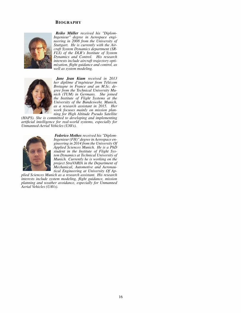
BIOGRAPHY[
Reiko Müller received his "Diplom-Ingenieur" degree in Aerospace engi-neering in 2008 from the University ofStuttgart. He is currently with the Air-craft System Dynamics department (SR-FLS) of the DLR’s Institute of SystemDynamics and Control. His researchinterests include aircraft trajectory opti-mization, flight guidance and control, aswell as system modeling.
Jane Jean Kiam received in 2013her diplôme d’ingénieur from TélécomBretagne in France and an M.Sc. de-gree from the Technical University Mu-nich (TUM) in Germany. She joinedthe Institute of Flight Systems at theUniversity of the Bundeswehr, Munich,as a research assistant in 2015. Herwork focuses mainly on mission plan-ning for High Altitude Pseudo Satellite
(HAPS). She is committed to developing and implementingartificial intelligence for real-world systems, especially forUnmanned-Aerial Vehicles (UAVs).
Federico Mothes received his "Diplom-Ingenieur (FH)" degree in Aerospace en-gineering in 2014 from the University OfApplied Sciences Munich. He is a PhDstudent in the Institute of Flight Sys-tem Dynamics at Technical University ofMunich. Currently he is working on theproject StraVARIA in the Department ofMechanical, Automotive and Aeronau-tical Engineering at University Of Ap-
plied Sciences Munich as a research assistant. His researchinterests include system modeling, flight guidance, missionplanning and weather avoidance, especially for UnmannedAerial Vehicles (UAVs).
16