Embed Size (px)
Citation preview
CONFIDENTIAL Copy •p LLIVI L(J.T'
NACA
RESEARCH MEMORANDUM LATERAL-CONTROL INVESTIGATION
OF FLAP-TYPE CONTROLS ON A WING WITH QUARTER-
CHORD LINE SWEPT BACK 35 0 , ASPECT RATIO 4, TAPER
RATIO 0.6, AND NACA 65A006 AIRFOIL SECTION
TRANSONIC-BUMP METHOD
By Robert F. Thompson
Langley Aeronautical Laboratory Langley Air Force Base, Va.
:2. Ta
TLAinIFIEU ST)CUMENT
UZCLA33IFID DATE 8-23-3- This document contains Cissstiied lttfOrsoi ,., -. fit
stteotieg the National DefenSe of the i J . • CFtOn EY Staten within the meaning of the Ssptoeage Aot1
at3iaodatittansw'l çANGk.. rt21 T C.i? its onaotboriaSd person in prohibited by law. I
nformation so classified may be Imparted rnly to persons In the military and naval nerviorn of the United States, appropriate vtotliae officers and emplopeeo of the Federal ]svern,eent Who have 5 legitimate Interest therein, and to United States citizens of knows loyalty and dineretion who of neoessity must be Informed thereof.
NATIONAL ADVISORY COMMITTEE FOR AERONAUTICS
WASHINGTON January 25, 1950
H
CONFIDENTIAL
https://ntrs.nasa.gov/search.jsp?R=19930086195 2019-05-29T06:51:11+00:00Z
NACA RM L9L12a CONFIDENTIAL
NATIONAL ADVISORY COMMITTEE FOR AERONAUTICS
RESEARCH MEMORANDUM
LATERAL-CONTROL INVESTIGATION
OF FLAP-TYPE CONTROLS ON A WING WITH QUARTER-
CHORD LINE SWEPT BACK 370, ASPECT RATIO Ii, TAPER
RATIO 0.6, AND NACA 65Aoo6 AIRFOIL SECTION
TRANSONIC-BUMP METHOD
By Robert F. Thompson
SUMMARY
As part of an NACA transonic-research program, a series of wing-body combinations are being investigated In the Langley high-speed 7- by 10-foot tunnel over a. Mach number range of about 0.60 to 1.20 by the use of the transonic-bump test technique.
This paper presents the results of an Investigation to determine the control-effectiveness characteristics of 30-percent-chord flap-type control surfaces of various spans on a semispan wing-fuselage model. The wing of the model had 350 of sweepback of the quarter chord, an aspect ratio of.0, a taper ratio of 0.6, and an NACA 65AO06 airfoil section parallel to the free stream. Lift, rolling moments, and pitching moments were obtained at several angles of attack throughout a small range of control-surface deflections. Most of the data are presented as control-effectiveness parameters which show their variation with Mach number.
In the Mach number region from 0.80 to 1.05 the results generally showed a marked decrease in lift and aileron effectiveness for all angles of attack. A relatively smaller decrease in negative values of pitching effectiveness occurs for the outboard controls In the same Mach number region at zero angle of attack.
CONFIDENTIAL
2 CONFIDENTIAL NACA RM L9L12a
INTRODUCTION
The need for aerodynamic design data in the transonic speed range has led to the establishment by the NACA of an integrated program for transonic research. As part of this transonic-research program, a series of wing-body configurations having wing plan form as the chief geometric variable are being investigated in the Langley high-speed 7- by 10-foot tunnel. A Mach number range from about 0.60 to 1.20 is obtained by using the transonic-bump test technique.
This paper presents the results of an investigation to determine the effects of 30-percent-chord flap-type control surfaces on the lift, pitching moment, and rolling moment of a semispan wing-fuselage model.. The model employs a wing with the quarter-chord line swept back 370, an aspect ratio of 4, a taper ratio of 0.6, and an NACA 65A006 airfoil section parallel to the free stream. The results of a previous investiga-tion of the same wing-fuselage model without control surfaces, giving additional aerodynamic data, may be found in reference 1. Previous control-effectiveness data for this series are presented in reference 2.
COEFFICIENTS AND SYMBOLS
CLlift coefficient (Twice lift of semispan model)
qS
C 1 rolling-moment coefficient at plane of symmetry (Rolling moment of semispan model"
qSb /
Cm pitching-moment coefficient referred to 0.25 (Twice pitching moment of semispan model'
qS
q effective dynamic pressure over span of model, pounds per
square foot( .-PV?)
S twice wing area of semispan model,- 0.125 square foot
b twice span of semispan model, 0.707 foot
mean aerodynamic chord of wing, 0.181 foot; based on relation-
2b/2
ship c2dy (using theoretical tip) -
- CONFIDENTIAL
NACA RM L9L12a CONFIDENTIAL 3
c local wing chord
Y spanwise distance from plane of symmetry
y spanwise distance from plane of symmetry to inboard end of control
P mass density of air, slugs per cubic foot
V free-stream air velocity, feet per second
M effective Mach number over span of model (2f /2cN dy)
Ma average chordwise local Mach number
MI local Mach number
(^2) A aspect ratio
B Reynolds number of wing based on
angle of. attack, degrees
5 control-surface deflection, degrees (measured in a plane perpendicular to control-surface hinge line, positive when control-surface trailing edge is below wing-chord plane)
x taper ratio (Rnnt
Tip chord
chord)
A angle of sweepback, degrees
ba control span measured perpendicular to plane of symmetry
CL I S
C =( 5
CONFIDENTIAL
Ii- CONFIDENTIAL NACA RM L9L12a
Cm8 (Cm'\
The subscript a indicates the factor held constant
MODEL AND APPARATUS
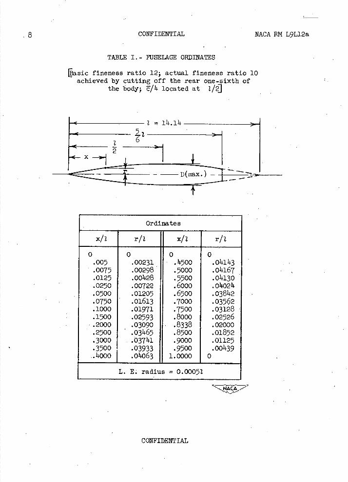
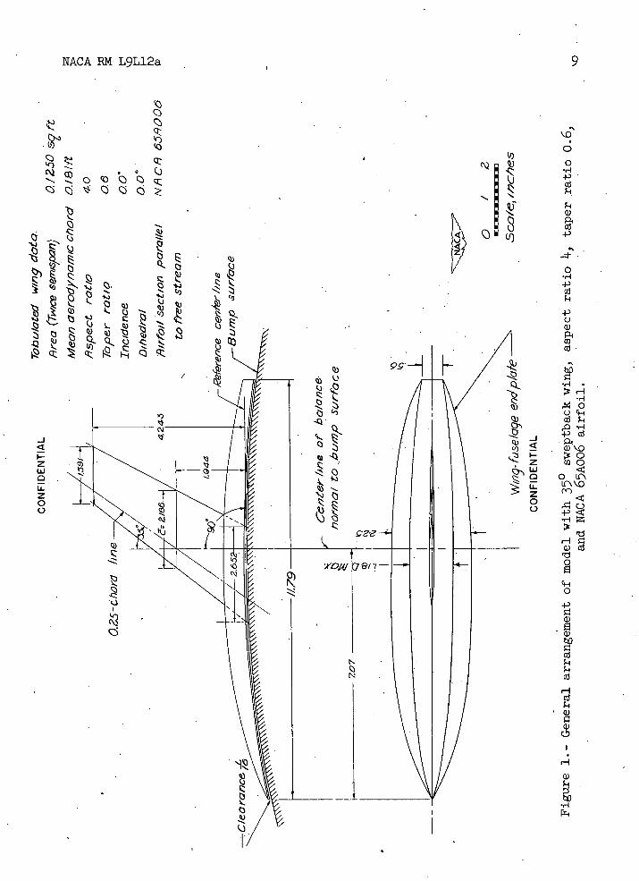
The wing of the semispan model had 350 of sweepback of the quarter-chord line, an aspect ratio of 4., a taper ratio of 0.6, and an NACA 65A006 airfoil section parallel to the free stream. The wing was made of beryllium copper and the fuselage of brass. A two-view drawing of the model is presented in figure 1 and ordinates of the fuselage of fineness ratio 10 can be found in table I. The wing was mounted vertically in the center of the fuselage and had no dihedral or incidence. The fuselage, which was semicircular in cross section, was curved to conform to the bump contour.
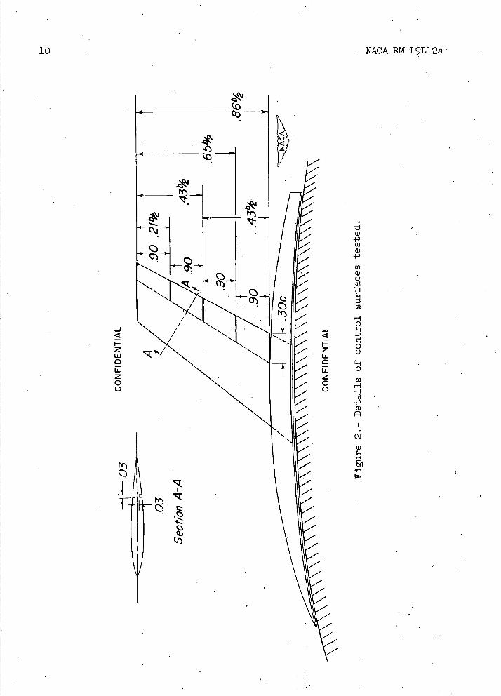
The control surfaces (aileron or flap) were made integral with the wing by cutting grooves in the upper and lower surface of the wing along the 70-percent-chord line. The control was divided into four equal spanwise segments from fuselage to wing tip (fig. 2). The desired control deflection of the spanwise segments was obtained by bending the metal about the 70-percent-chord line. After being bent, the grooves were filled with wax, thus giving a close approach to a 30-percent-chord sealed plain flap-type control surface.
The model was mounted on an electrical strain-gage balance and the aerodynamic forces and moments were measured with a calibrated potentiom-eter. The balance was mounted in a chamber within the bump, and the chamber was sealed except for a small rectangular hole through which an extension of the wing passed. This hole was covered by the fuselage end plate which was approximately 0.03 inch above the bump surface.
CORRECTIONS
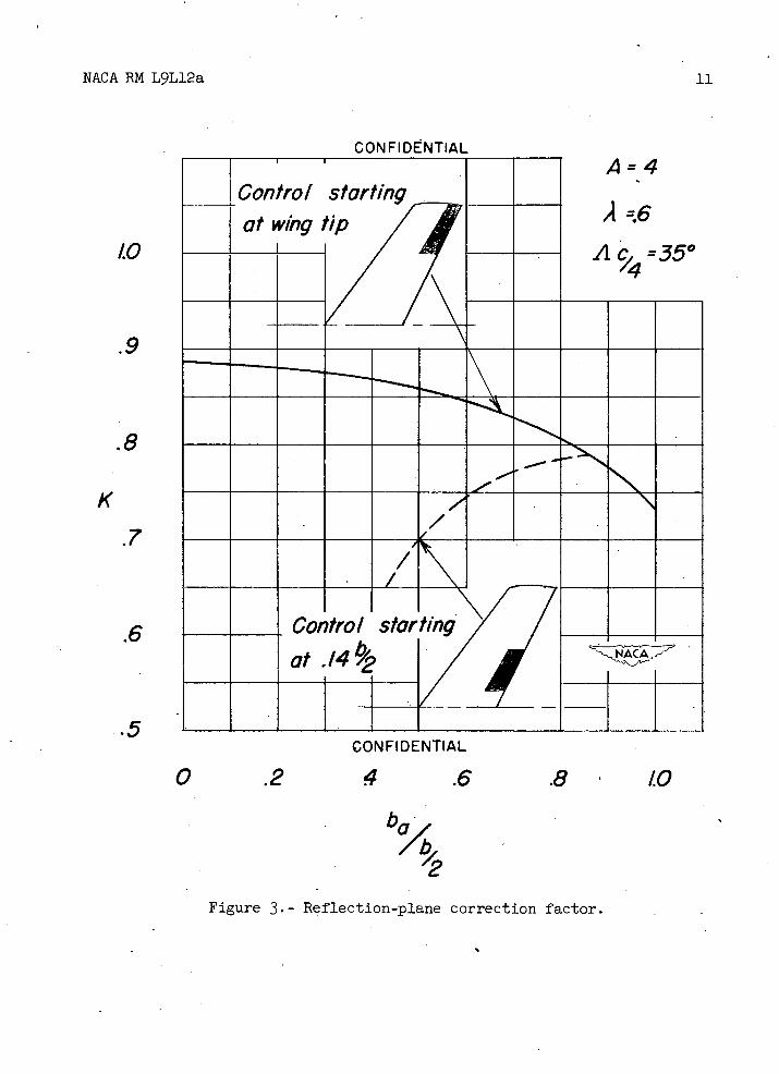
The aileron-effeátiveness parameters C1 8 presented represent the aerodynamic effects on a complete wing produced by the deflection of the control surfaces on only one semispan of the complete wing.. Reflection-plane corrections which have been applied to the aileron-effectiveness parameters throughout the Mach number range tested are given in figure 3 and were obtained from unpublished experimental corrections obtained at low speed (M = 0.25) and theoretical considerations. Although the corrections are based on incompressible conditions and are only valid
CONFIDENTIAL
NACA RM L9L12a CONFIDENTIAL 5
for low Mach numbers, they were applied throughout the Mach number range in order to give a better representation of true conditions than would be shown by the uncorrected data. No attempt has been made to correct the rolling-moment data for increments of rolling moment due to the lift increase on the wing-fuselage end plate (fig. 1) produced by control-surface deflection. This effect is believed to be of little significance for short-span outboard control surfaces but may be of importance for control surfaces that extend outboard from the wing-fuselage intersection.
The lift-effectiveness ani pitching-effectiveness parameters represent the aerodynamic effects of deflection in the same direction of the control surfaces on both semispans of the complete wing; therefore, no reflection-plane corrections are necessary for the lift and pitching-moment data.
The change in control-surface deflection due to load was measured and found to be negligible. No corrections were applied for model twist due to air load but these corrections are believed to. be small.
STS
• The tests made in the Langley high-speed 7- by 10-foot tunnel, utilized an adaptation of the NACA wing-flow technique for obtaining transonic speeds. The technique used involves the mounting of a model. in the high-velocity flow field generated over the curved surface of a bump located on the tunnel floor (see reference 3).
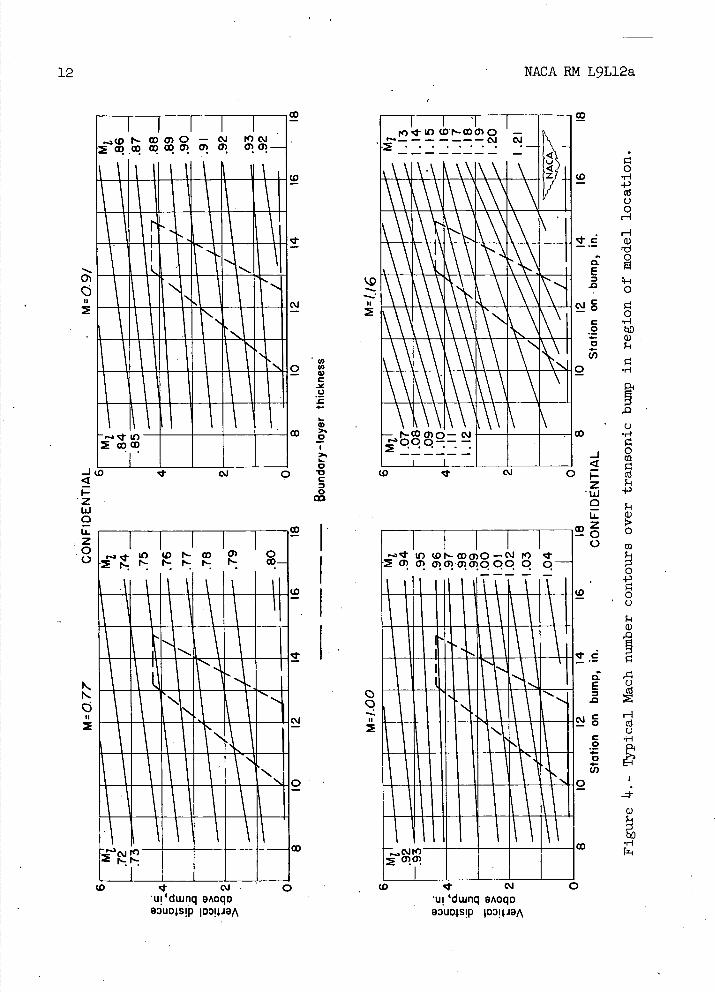
Typical contours of local Mach number in the viclnity of the model location on the bump, obtained from surveys with no model in position, are shown in figure 4. It is-seen that there is a variation of Mach number of about 0.04 over the model semispan at low Mach numbers and from 0.06 to 0.07 at the highest Mach numbers. The chordwise Mach number variation is generally less than 0.01. The effective Mach number over the wing semispan is estimated to be 0.02 higher than the effective Mach number where 50-percent-span outboard ailerons normally. would be located. No attempt has been made to evaluate the effects of this chordwise and spanwise Mach number variation. The long-dashed line. shown near the root of the wing in figure 4 indicates a local Mach number that is 5 percent below the maximum value and represents the extent of the bump boundary layer. The effective test Mach number was obtained from contour charts similar to those presented in figure t by use of the relationship
M=i- /2 cMdy
CONFIDENTIAL
6 CONFIDENTIAL NACA RM L9L12a
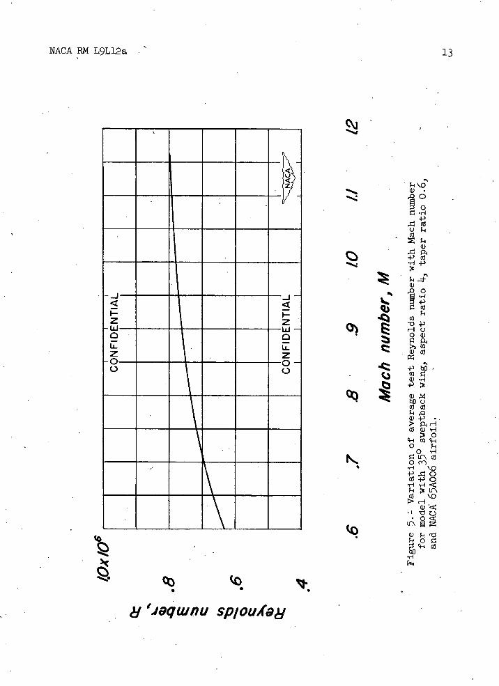
The variation of test Reynolds number with Mach number for average test conditions is presented in figure 5. The Reynolds numbers are based on the mean aerodynamic chord (0.181 ft).
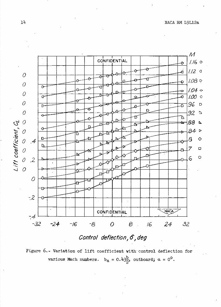
Force and moment data were obtained with control surfaces of various spans through a Mach number range of 0.60 to 1.16, an angle-of-attack range of -80 to 80 , and a control-deflection range of 00 to 100 . Addi-tional data on the 43-percent-span outboard control surface (fig. 2) were obtained up to a deflection of 300.
RESULTS AND DISCUSSION
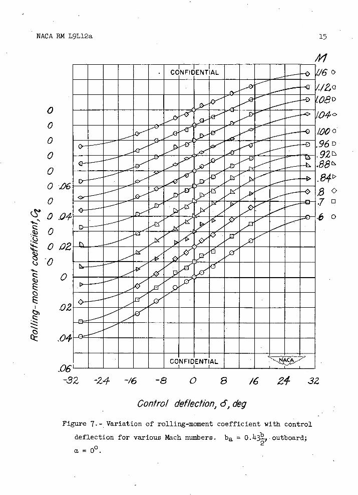
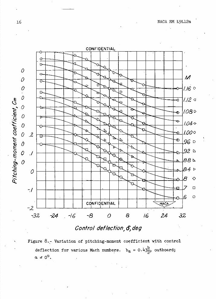
Lift, rolling-moment, and pitching-moment coefficients - plotted against control-surface deflection for the outboard 43-percent-span control at an angle of attack of 0 0 - are presented in figures 6, 7, and 8, respectively, and are representative data plots from which control-effectiveness parameters were obtained. The curves of figures 6, 7, and 8 are typical of the curves for each of the other control configurations tested. The data were obtained at various positive control deflections throughout the angle-of-attack range, and, inasmuch as the wing was symmetrical, data obtained at positive control deflections and negative angles of attack were considered, with appropriate regard to signs, to be equivalent to data that would be obtained at negative control deflection and positive angles of attack and were plotted as such.
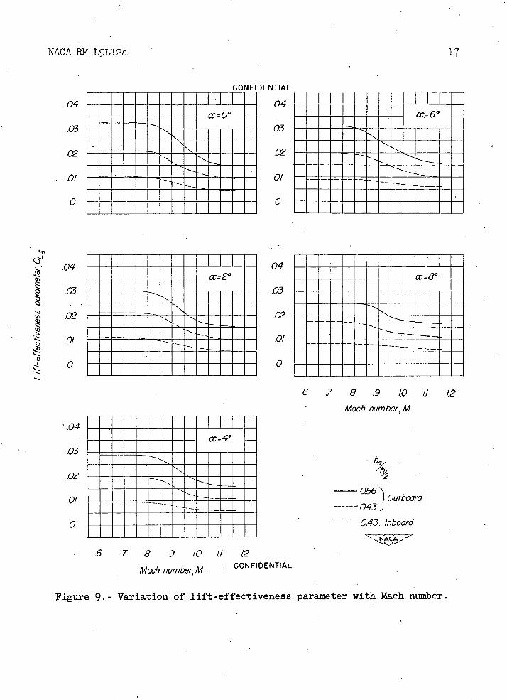
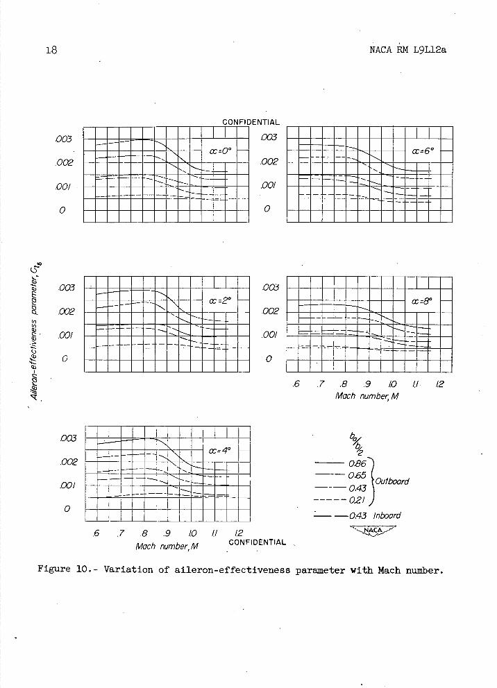
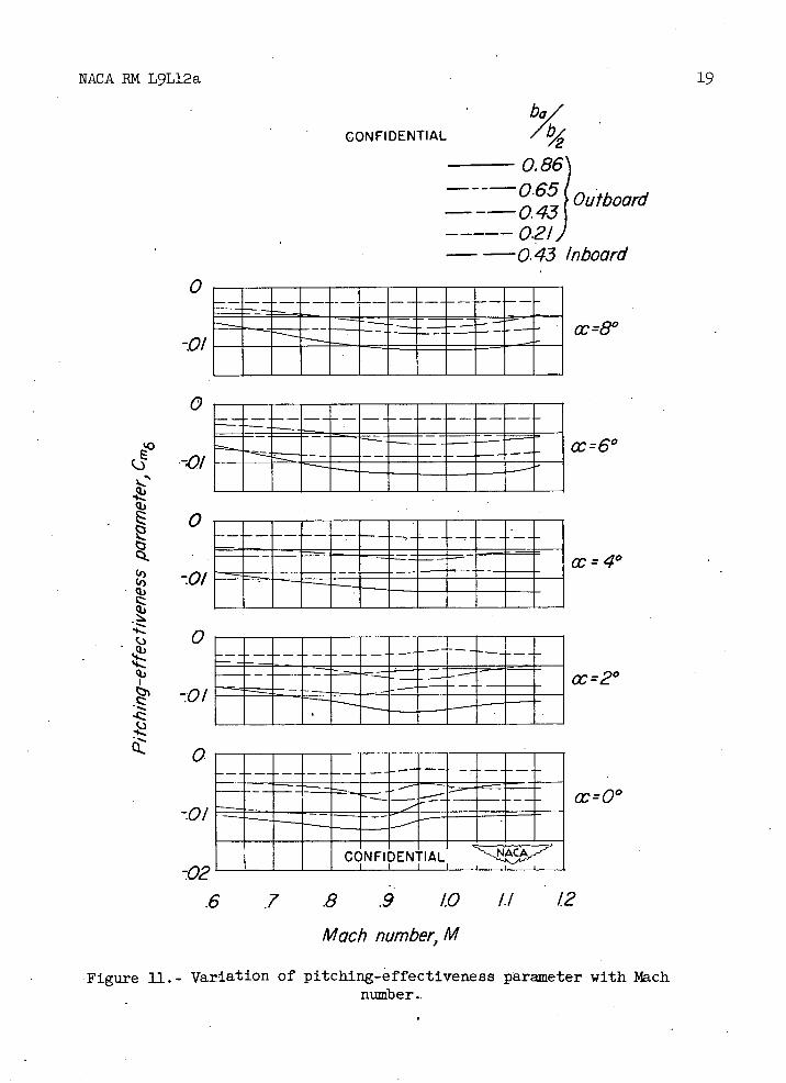
Lift-, aileron-, and pitching-effectiveness parameters plotted against Mach number are presented in figures 9, 10, and 11, respectively. These parameters were obtained from figures 6 to 8 and similar plots of the test data for the various control-surface configurations. The data for all configurations had a linear variation with control-surface deflection for a deflection range of approximately ±10 0 , and it was within this range that the slopes to obtain control-effectiveness parameters were measured.
In general, a marked decrease in lift-effectiveness and aileron-effectiveness parameters occurs between Mach numbers of 0.80 and 1.05 (figs. 9 and 10) for all angles. of attack tested. A relatively smaller decrease in negative values of pitching-effectiveness parameter occurs for the outboard controls in about the same Mach number region at zero angle of attack but this decrease is not apparent at the higher angles of attack (fig. 11).
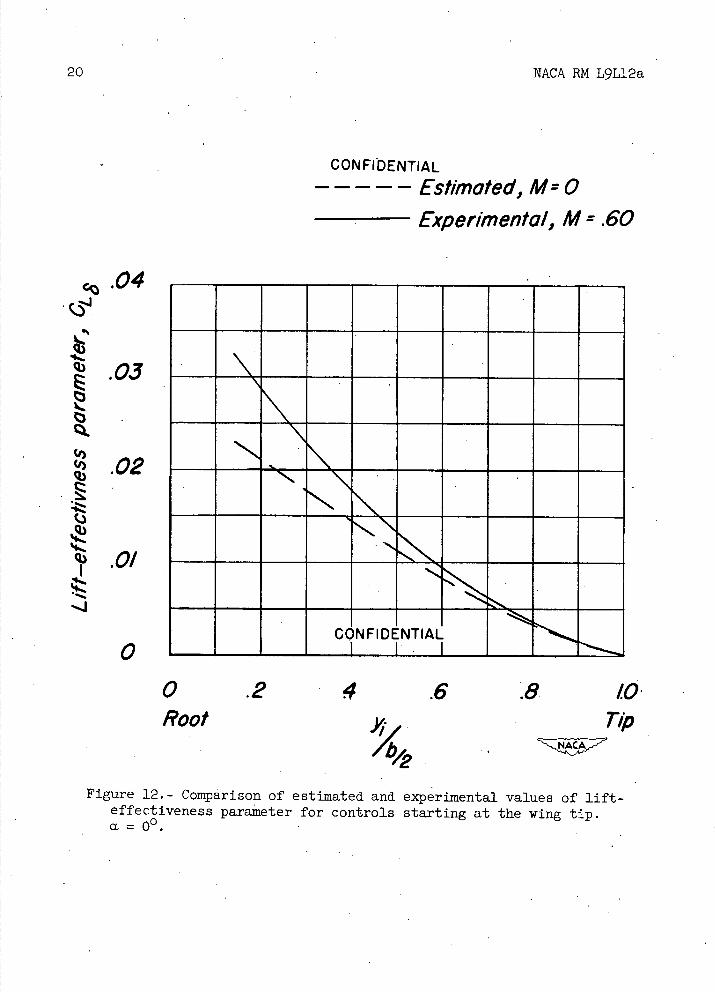
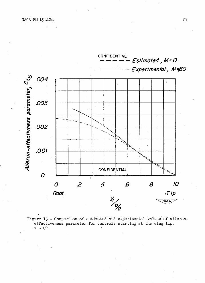
For controls starting at the wing tip, figures 12 and 13 are a comparison of the values of lift-effectiveness and aileron-effectiveness parameters obtained in this investigation at M = 0.60 with those
CONFIDENTIAL
NACA EM L9L12a CONFIDENTIAL 7.
estimated by reference 4 at M = 0. Experimental values are in good agreement with estimated values for short-span outboard controls. As the control span is increased, the experimental values become higher than estimated ones and, in general, do not give good agreement.
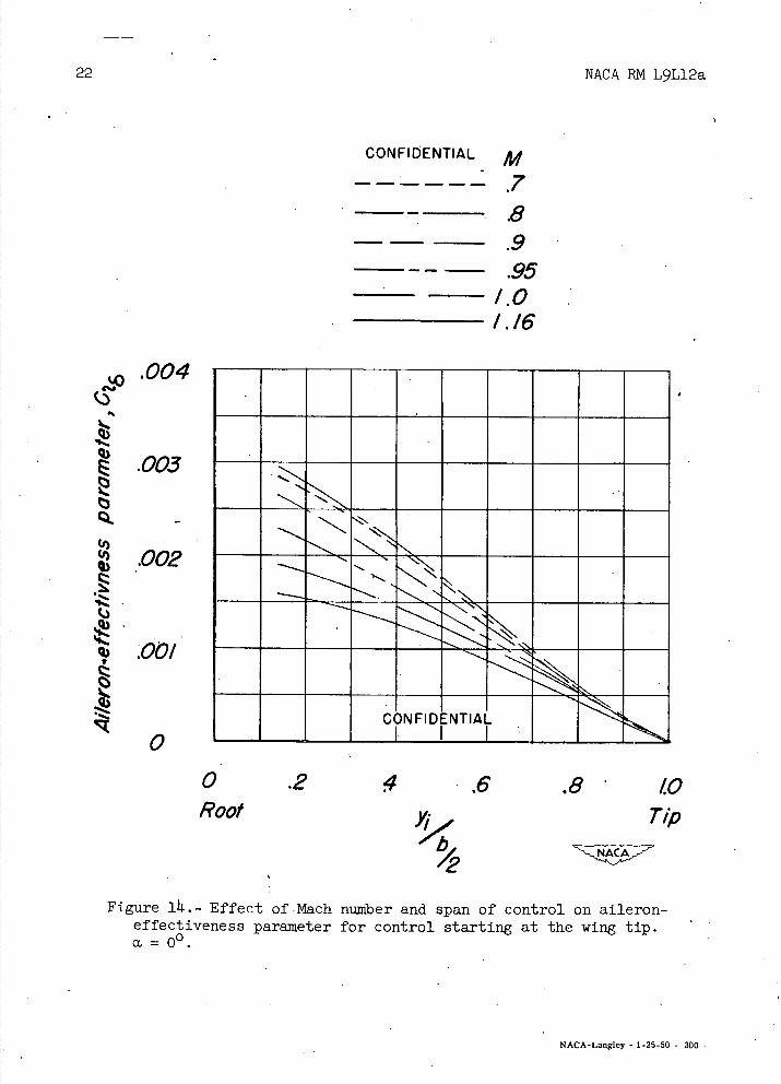
The variation of aileron-effectiveness parameter with Mach number and control span for controls starting at the wing tip is shown in figure lii.. For any given control span there is a large variation of aileron effectiveness with Mach number (figs. 10 and 14).
Langley Aeronautical Laboratory National Advisory Committee for Aeronautics
Langley Air Force Base, Va.
REFERENCES
1. Sleeman, William C., Jr., and Becht, Robert E.: Aerodynamic Charac-teristics of a Wing with Quarter-Chord Line Swept Back 370, Aspect Ratio 4, Taper Ratio 0.6, and NACA 65A006 Airfoil Section. Transonic-Bump Method. NACA EM L9B25, 1949.
2. Vogler, Raymond D.: Lateral-Control Investigation of Flap-Type Controls on a Wing with Quarter-Chord Line Swept Back 450, Aspect Ratio 11, Taper Ratio 0.6, and NACA 65A006 Airfoil Section. Transonic-Bump Method. NACA RN L9F29a, 1949.
3. Schneiter, Leslie E., and Ziff, Howard L. Preliminary Investigation of Spoiler Lateral Control on a 11-2° Sweptback Wing at Transonic Speeds. NACA RN. L7F19, 1947.
11. Lowry, John G., and Schneiter, Leslie E.: Estimation of Effectiveness of Flap-Type Controls on Sweptbaek Wings. NACA TN 1674, 1948.
CONFIDENTIAL
CONFIDENTIAL NACA FM L9L12a
TABLE I. - FUSELAGE ORDINATES
[Basic fineness ratio 12; actual fineness ratio 10 achieved by cutting off the rear one-sixth of
the body; /4 located at 1/2]
l=114..lii.
-.l 1
2 x-,.1
D(max.)LI
Ordinates
x/l r/l xli r/l
0 0 0 0 .005 .00231 .500 .04143
• .0075 .00298 .5000 .o4167 .0125 .00428 .5500 .011.130 .0250 .00722 .6000 .04024 .0500 .01205 .6500 .03842 .0750 .01613 .7000 .0352 .1000 .01971 .7500 .03128 .1500 .02593 .8000 .02526 .2000 .03090 .8338 .02000 .2500 .03465 .8500 .01852 .3000 .03741 .9000 .01125 .3500 .03933 .9500 .00439 . 11.000 .011.063 1.0000 0
L. E.. radius = 0.00051
CONFIDENTIAL
NACA RM L9L12a
I)) 0
0
4)
cd
ci
IIi 44
44 44
iu
ciz
a)
+
0
Cd
C)
a) P, a) cd
oq-4
a) '-0
tao
0
•-i2
H a)
0
0
-J
I-
z ILi
-J
I-z w a
LI-
z
0 C-,
z 0 0
+
a)
a)
cd
Cd
i-I Cd
PLI
a) Ct'
H
a)
10 NACA RN L9L12a
'4..,
AM
Cd
al
Cd
Ss
NACA RN L9L12a 11
CONFIDENTIAL
10
.9
.8
K.7
.6
I
Control starting at wing tip
1
A=4
A 6 J17350 __
/
Control starting at 14(g
CONFIDENTIAL
0 .2 4 .6 .8 10
ba,
'2 Figure 3.- Reflection-plane correction factor.
12 NACA RN L9L12a
0)
C 0
I-
II"I'ItIIiL1I III1iIIi1LI1
Ills llm^I
'ILIlIIIInhIIl islillivillivill 1211112111111111 "I'll" NONE
w
0 CD
4-) Cd 0 0
H
o
.0
j.I OD
ri Q CD CJ 0
z 0 .J +) z
LU - U-
MZ
.0 C-)
K N-0 II
0 0 II
U o
0
0 0
C)
:.
•: E
H
.0 a3 0
C r1 0
0 Cl)
bjD
ci)
IIIIIIIINII. LIlLIlIflhlI I'IHhL"IIi "null. InhII"iI illillEl..
JUIRU
I"III'unhI"I'I. 'I'ItIIIIIIAn!t ihiIiIIIiI'i'iI 'llhIIIliIlI"iI I'1"I'II'Ii'III. I'IuhIIin" IIIIIUIIIIII.
MEMOCD It C.J 0
(0 10, c.J C-,
ui'dwnq eoqo U! 'duinq aoq e3UDSIp I03109f\
93UD4S!p IO3109A
a) ro
,.. r
h. q)
cLi.
V Cd
+) .) u
oo
c-i rc-4 o
0 -i
I s o çr
H r4
a) •: .tc-)
F-4 rd
c-i c3 -H 1Li
NACA RN L9L12a
13
4
17
I-z
U- z.
-0— o
z•
0
z —-- 0
c_)
— _J --
—Ui--
\.-
cc
cY 'eqwnu Sp/OUt9c5l
14
NACA RM L9L12a
MONEEM iCONFIDENTIAL
I I I U.. MEMMMMUi.i- Ep MENEFAMONi-U.. n0N.own I am0 1 momISMME -9
NEW
MEMO EM M
_.
PWAMWOE0
NNEEM M
104-MEMEUFU4UUUUUU
M1000019PINEW owl
NNEEM E MENEENE iUUUiUUUU
NU..U.U..U...U.0 MENNEWEUUU1__
(2
08D
O4 000
D
2
8
0
0
0
0
0
(3J0
•q) .o .4
0.2
-24- -/6' 8 0 8 16 24 32 :4
-32
Control deflect/on, 6, deg
Figure 6.- Variation of lift coefficient with control deflection for
various Mach numbers. ba = O.43 ., outboard; a =
0 0 0 0 rs
0
0.02
Q.) E
E02
.04
.06
-32 -24 -16 -8 0 8 / 32
NACA RN L9L12a 15
/;4
Control deflection, 6, deg
Figure 7 . - . Variation of rolling-moment coefficient with control
deflection for various Mach numbers. ba = 0.4outboard;
a. = 00.
16
NACA RN L9L12a
CON Fl DENTIAL
-2 -32
70
D
0
0
-24.-/' -8 0 8 16 24 32
Control deflection, 6 deg
0
0
0
-S .(J
0.2
.1
0
-I
ME
Figure 8.- Variation of pitching-moment coefficient with control
deflection for various Mach numbers. ba = 0.43t, outboard;
a. 00.
NACA RM L9L12a
17
C ON FIDE NT IA
.04
.03
.02
.0/
0
04MA
.03
.02
.0/
0
x,= 60
12
.04
.03
.02
.0/
0
.6 .7 .8 .9 10
• Mach number, M
.04 Q)
.03 QL
.02
.0/
0
.04cc=4°
03
02
086 .0/
0.43 J Outboard
0 ---043 Inboard
.6 .7 .8 .9 10 1/ 12
Mach number, MCONFIDENTIAL
Figure 9.- Variation of lift-effectiveness parameter with Mach number.
L
5
2cc=6°
003
.002
.00/
0
a () (,-)
1
I
.003
.00/
0
r =20003
.002
.00/
0
X=80
.6 .7 .8 .9 /0 1/ 12 Mach numbeç M
18
NACA RN L9L12a
a'
026 0.65
Outboard 0.43
------02/
—0.43 Inboard
.6 .7 .8 .9 /0 II 12
Mach number, M CONFIDENTIAL
Figure 10.- Variation of aileron-effectiveness parameter with Mach number.
.003
x=40 .002
.00/
0
NACA RM L9L12a
'0
E
I I
CONFIDENTIAL /b,
0.86')
Outboard
-----0.2/ - —0.43 Inboard
0
uiiiiiii -uiui:i-
PPA
-0/
02
IMMEMEMMEM-ME MMMMEMMUMME EMEMEMMEMEME .0000 CONFIDENTIAL , ^A
cc = 00
.6 .7 .8 10 I.! 12
Mach number, M
Figure U. - Variation of pitching-effectiveness parameter with Mach number..
20 NACA RN L9L12a
CONFIDENTIAL
Estimated, M=0
Experimental, M .60
04
.03
.02
U
CONFIDENTIAL
rk
0 .2 4 .6 .8 /0 Root j., Tip
Figure 12.- Comparison of estimated and experimental values of lift-effectiveness parameter for controls starting at the wing tip. a. 00.
(I)
.002
.00!
I 1- --t I I
NACA FJVI L9L12a 21
44
Q)
.003
CON Fl DENTIAL
Estirnated,M=0 Experimental, M60
MMO
CONFIDENTIAL
00 2 4 .6 .8 10
Root. Tip
4. Figure 13.- Comparison of estimated and experimental values' of aileron-
effectiveness parameter for controls starting at the wing tip. CL = 00.
22
NACA RN L9L12a
CONFIDENTIAL M ------ .7
—: .8 -- .9, ___-- .95
1.0 1.16
.004
.003
.002
ZqDCI
0
-
CONFIDENTIAL
0 .2 4 .6 .8 10 Root Tip 4 ,
Figure 14, Effect of . Mach number and span of control on aileron-effectiveness parameter for control starting at the wing tip. ci = 00.
NACA-Langley - 1-25-50 - 300