Embed Size (px)
Citation preview
RESEARCH MEMORANDUM
TESTS OF THE NACA 0010-l. 50 40/l. 051 AIRFOIL SECTION
AT HIGH SUBSONIC MACH NUMBERS
By Albert D. Hemenover
Ames Aeronautical Laboratory Moff ett Field, Calif.
NATIONAL ADVISORY COMMITTEE FOR AERONAUTICS
WASHINGTON September 4, 1953
?q ,‘, - : --- - -

EACARMA53G09. .: .; . _
NATIOEAL ADVISORY COMMITTEE FOR AEROEAUTICS
TESTS OF TBE NACA 0010-1.50 &O/l.051 AlRFOIL SECTION
ATRIGRSUWOEICMACHNCMBERS
By Albert D. Hemenover
S-Y
Aerodynamic characteristics of the EACA 0010-1,~ 40/1.051 air- foil section have been determined from wind-tunnel tests at Mach numbers from 0.3 to 0.9. The corresponding Reynolds number variation was from approximately 1 X lo6 to 2 X 10⁶. These results for sn airfoil with a leading-edge radius of 1.w percent of the chord ere compared with those of a previous investigation of the effects of leadfng-edge-radius v-art- ation from 0.27 to 1.10 percent of the chord on the chsracteristics of a lo-percent-thick, SgrlIIIlletrfcal airfoil section at high subsonic Mach numbers.
The comparison Indicates small increases of the Mach numbers for lift and drag divergence at low lift coefficients for the section with the largest leading-edge radius.
IRTRODLK!TIOE
In reference 1, the effects of systematic reduction of the leading- edge radius on the variation with Mach number of the aerodynamic charac- teristics of a lo-percent-thick, smetrical airfoil section were reported. To examine the effects of an fncrease fn leading-edge radius for the same airfoil section, the present investigation was undertaken in the Ames I- by 3-l/2-foot high-speed wind tunnel. The afrfoil is of the modified EACA four-digit series (see ref. 2), with maximum thickness at the &O-percent-chord position and &th a traLUng-edge angle of l2O. In the present fnstance the airfofl leading-edge radius is 1.50 percent of the chord; whereas fn reference 1 the radii were 1.10, 0.70, and 0.27 percent of the chord. To facutate comparfson, the results of refer- ence 1 are reproduced in the present paper.
2 NACA RM A53GO9
a0
Ca
Cl
czmax
cm C/4
M
Ma
NOTATION
section lift-curve slope at zero lift coefficient, per deg
section drag coefficient
sectionlift coefficient
maximum section lift coefficient
section pitching-moment coefficient about the quarter-chord point
Mach number
drag-divergence Mach number, defined as the Mach number at dcd whfch dM
(lb = 0.1
= constant lift-divergence Mach number, defined aa the Mach number corre-
sponding to the initial Election point on curves of section lift coefficient as a function of Mach number at constant angle of attack
Reynolds number
section angle of attack, deg
AIRFOIL DESIGNATION
The airfoil section of the present investigation is designated as: NACA 0010-1.50 40/1.051. The first digit of the airfoil designation fndi- cates the camber in percent of the chord; the second, the position of the camber fn tenths.of the chord from the leading edge; and the,third and fourth, the maximum thickness in percent of the chord. The decimal number following the dash is the leading-edge-radius index; the leading-edge radius as a fraction of the airfoil chord is given by the product of the radius index and the square of the thickness-chord ratfo. A radius index of 1.10 is standard for the NACA four-digit-series airfoil sections. The two digits mediately preceding the slant represent the position of maxfmum thickness in percent of the chord from the leadfng edge. The last decimal number is the trailfng-edge-angle index, the angle being twice the arc tangent of the product of the angle index and the thickness- chord ratio. .
NAGA RM A53G09 3
c The coordinates of the airfoil investigated are given fn table I. This airfoil profile is illustrated in figure 1 along with those of reference 1 to show the influence.of leading-edge radius on profile shape. I
APFARATrJs AND TESTS
The test was conducted in the Ames I- by 3-l/2-foot high-speed wind tunnel, a low-turbulence two-dimensional-flow tind tunnel.
The airfoil model was of 6-inch chord and was constructed of aluminum alloy. The model completely spanned the l-foot dimension of the tunnel test section. Contoured sponge-rubber gaskets compressed between the model ends and the tunnel walls preserved two-dimensional flow by preventing end leakage.
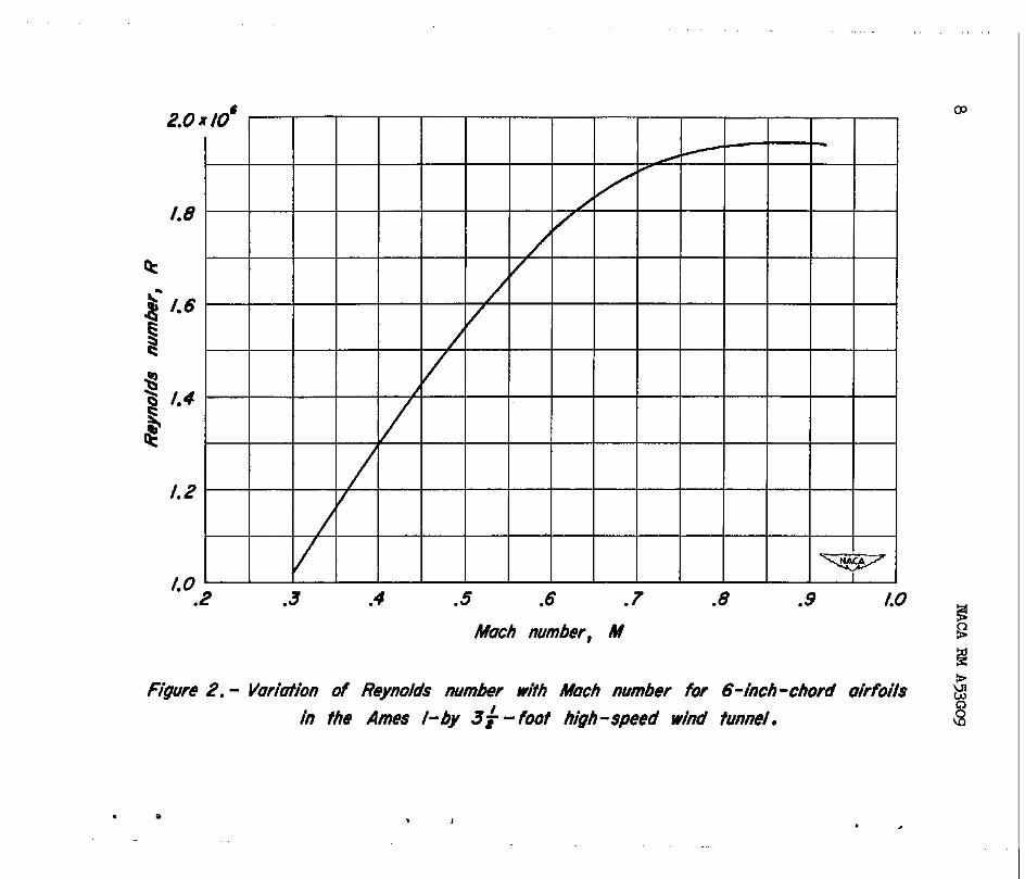
Measurements of lift, drag, and quarter-chord pitching moment were made simultaneously at Mach numbers from 0.3 to approximately 0.9 for the model at angles of attack increasing by increments of lo or 20 from -2O to l2O. Thfs range of angles was sufficient to encompass nega- tive lift at all Mach numbers and the lift staU up to a Mach number of 0.8. The Reynolds number variation with Mach number for the test is fllustrated in figure 2.
Lift forces and pitching moments were evaluated from measurements of the pressure reactions on the tunnelwslls of the forces on the air- , foF1. Drag forces were determfned from wake-survey measurements made with a rake of total-head tubes.
RESULTS AND DISCUSSION
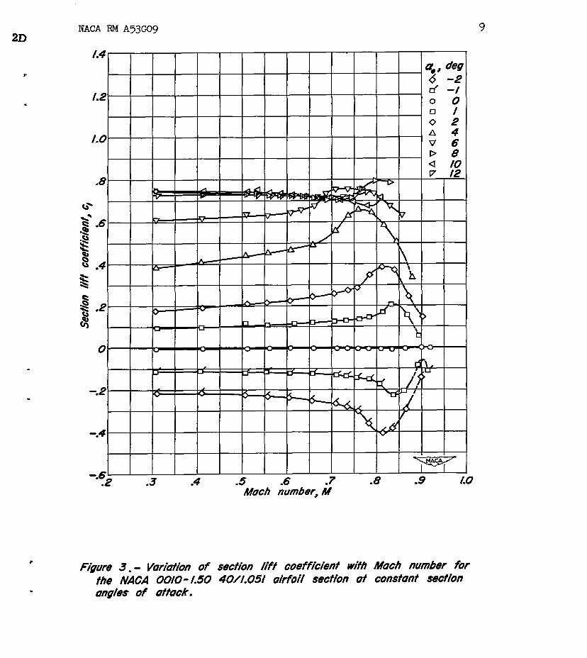
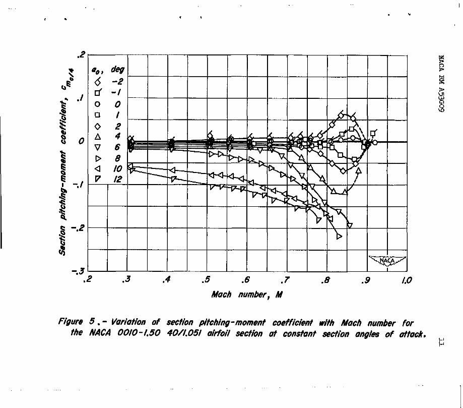
Section lift, drag, end quarter-chord pitching-moment coefficients are presented as functfons of &ch number at constant angles of attack in figures 3, 4, and 5, respectively, for the NACA 0010-1.50 40/1.051 airfoil section. Corrections for tunnel-wall interference by the methods of reference 3 have been applied to the data. The results ahown as dashed portions of the curves should be used with caution because of the possible influence of wind-tunnel choking effects in this reeon,
Lift Characteristics
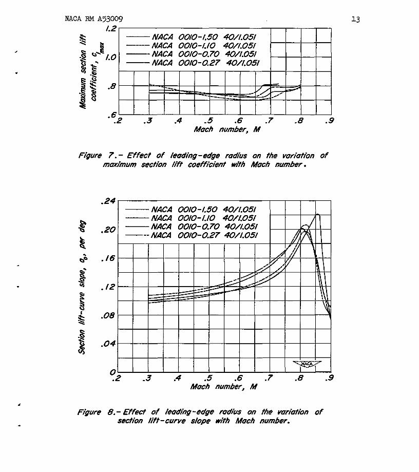
The variation of lift coefficient with angle of attack at constant Mach number 1s shown in figure 6 for the RACA 0010-1.50 40/1.051 airfoil section. Maximum lift coefficient as a function of Mach number is pre- sented in figure 7 for leading-edge radfi of 1.50, 1.10, 0.70, and
4 NACA RM A53Go9
0.27 percent of the chord, respectively. The variation of lift-curve slope with Mach number is presented fn figure 8 for the various leading- edge radii. :
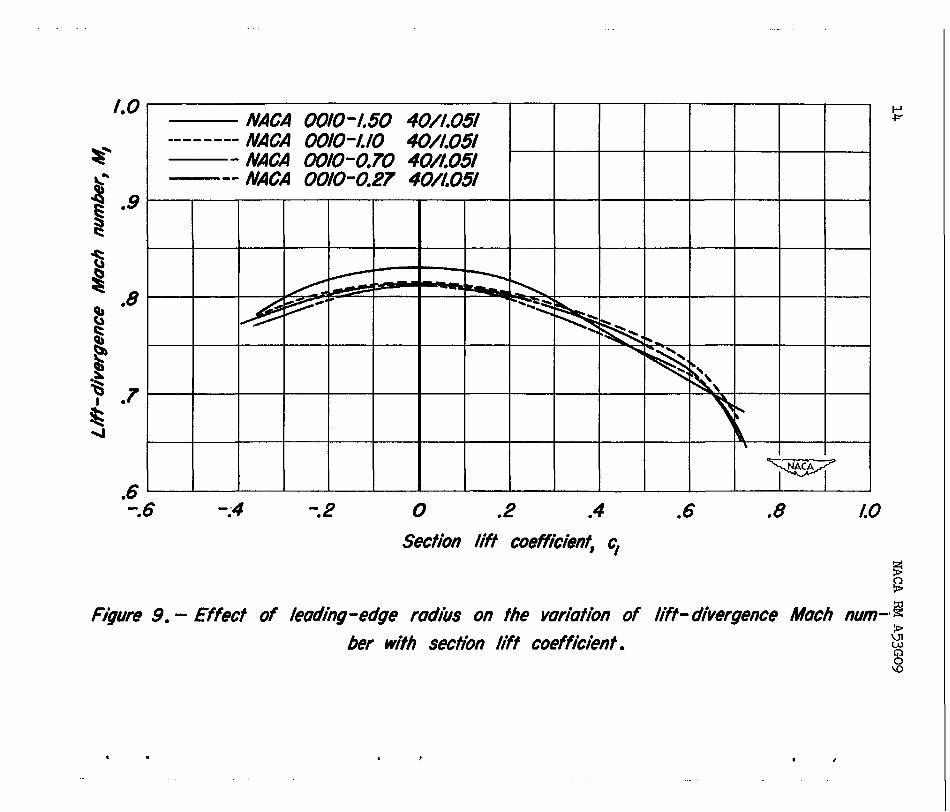
Lift-divergence Mach number as a function of lift coefficient is presented in ffgure 9 for the leading-edge radii investigated. Although little change in the Mach number for lift divergence at low and moderate lift coefficients is observed for a leading-edge-radius variation from 1.10 to 0.27 percent of the chord, an increase of approximately 0.02 Mach number at low lift coefficients is noted for the leading-edge radius of 1.50 percent of the chord.
Drag Characteristics
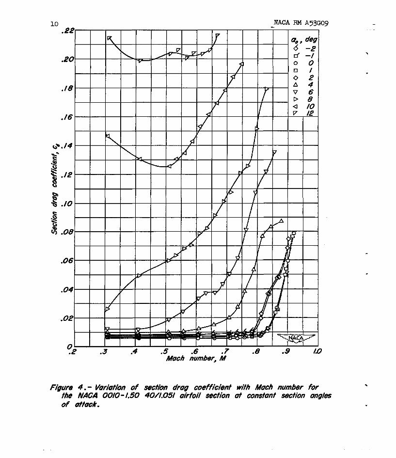
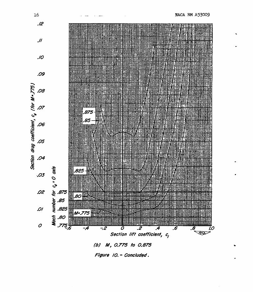
Drag coefficient as a function of lift coefficient at constant Mach number is shown in figure 10 for the NACA 0010-1.50 40/1.051 air- foil section. A peculiar trend in the drag polars is observed at Mach numbers.above 0.8. At Mach numbers above 0.825, figure 4 shows that the drag coefficients at Oo and lo are essentially the same. This unusual characteristic has been observed in low-speed tests of airfoils having large leading-edge radii. Ithas been attributed to the fact that the preseure gradient on one surface becomes less adverse as the lift coefficient is varied from zero, increasing the relative extent of lami- nar flow on this surface with consequent reduction ti drag.
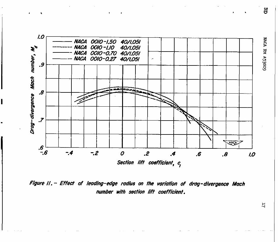
The variation of drag-divergence Mach number with lift coefficient is presented in figure 11 for the various leading-edge radii. At small to moderate lift coefficients, the drag-divergence Mach number increases with ticreases in leading-edge radiua.
.
Pitching-Moment Characteristics
Pitching-moment coefficient as a function of lift coefficient at constant Mach number is presented in figure 12 for the NACA 0010-1.50 40/1.051 airfoil section.
CONCLUSIONS
Comparison of the results of a wind-tunnel test at high subsonic Mach numbers of a lo-percent-thick, symmetrical modified NACA four-digit- series airfoil section havln@; a leading-edge radius of 1.50 percent of the chord with previously determined results for the same basic airfoil section with leading-edge radii of 1.10, 0.70, and 0.27 percent of the chord indicate but two principal effects of leading-edge radius:
.
,
NACA RMA53GOg 5
1. The Mach number for lift divergence for the airfoil with the largest leading-edge radius is approximately 0.02 higher at low lift coefficients than for the other airfoils.
2. The Mach number for drag divergence fe generally increased at low and moderate l3ft coefficients with increasing leading-edge radius.
Ames Aeronautical Laboratory National Advisory Committee for Aeronautics
Moffett Field, Calif., July 9, 1953
REFZRENCES
1. Summers, James L., and Graham, Donald J.: Effects of Systematic Changes of Trailing-Edge Angle and Leading-Edge Radius on the Variation with Mach Number of the Aerodynamic Characteristics of a l&Percent-Chord-Thick RACA Airfoil Section. HACA RM AgGl.8, 1945).
2. Abbott, Ira H., von Doe&off, Albert E., and Stivers, Loufs S., Jr.: Summary of AfrfoFl Data. NACA Rep. 824, 1945.
3. Allen, H. Julfan, and Vincenti, Walter G.: Wall Interference fn a Two-Dimensional-Flow Wind 'Tunnel, with Consideratfon of the Effect of Compressibility. NACA Rep. 782, 1944.

6 NACA RM A53GO9
TABLE I.- COORDIIWCES FOR THE NACA 0010-1.50 441.051 AIRFOIL SECTION
[Stations and ordinates in percent of airfoil chord]
station Upper or lower surface ordinate
0 0
::5 1.110 1.328 1.25 1.653 2..50 2.183
75:: 2.805 3.203 10 3.500 15 3.948 20 4.295 25
E sz 5:ooo
z 4.783 4.197 2 3.338
2.305
;; 1.193 .638 100 .lOO ,.E. radius: 1.50-percent chord
Y@xJ7-

NACA RM A53GO9
NACA 00/O-1.50 40//.05/ &foir’/ section
NACA 00/O-/./O 40//,05/ &foil se&ion
NACA 0010-0.70 4O/LO5/ ukfoor’/ secfion
NACA 00/O-0.27 40/i/.05/ a&foil section T
c Figufe I.- hfluence of /eudiffg-edge fffdhs on pfofBe dupe.
.
f.8
I.0 . 2 .3 .4 .5 .6 .7 .8 .9 i.0
Mach number, M
F&we 2. - Voriofion of Reynolds mmber with Mach number for 6-inch-chord airfoils
in the Ames f-by 3; - foot high-speed wind tunnel.
. m I I I
2D NACA RM A5309 9
l
.
“i I /.2
.8
.3 .4 .5 .6 .7 Much number, M
Figwe 3. - Vurht~on of secf/on /if.+ coeffkienf wiih Much number for fhe NACA 00/O-/.50 40//.05/ ukfo// secfion of constonf secfion mgfes of utfuck.
10 NACA RM A53GUg
I I I I I I I I IPI I I I
Mach number; M
CT 41
6 d 0
cl
0 II
Figure 4.- Viriofion of section drag coeff/cienf wifb M&b number for fbe NACA 00/O- I.50 40//.05f oirfo// secfion at constant secfion angles of affuck.
=ot deg 6 -2 d -I 0 0 0 J 0 2 A 4 V 6 b 8 a 10 v 12
.3 .I .5 .6 .7 .8 Mach number, #
figure 5. - Variation of sect/on pitching -moment coefficil’ent wifh Mach number for the NACA 00/O-/.50 40//.05/ okfoil secfk~ at consttrnt &ion angles of &tuck.
F

.- .- .“I# .a- .“d .Y,d .I” .,GY ,IV .IIn# .“” .VGH
I I , I I I ,I I II I I I I I I I I I II I I I I I I I II I I I I I I I I.1 1 I I III I L I I I I\ I Ill I\ I
.8 / / i ii ’ di5
I I I I I
I I
-.4
.I .m .40 .fl .fl .60 .6Z?5 .65 .675 .70 .725 .75 .775 .&J -825 -85 .8n -90
L , .
NACA F&f A53GOg
L2 * ‘e
-8 “, .t LO -- NACA 0010-0.70 40//.05/ 03 - NACA 00/O-0.27 40//.05/
e :s .g$ -8
8” .6
.2 .3 .4 .5 .6 .I .8 .9 Much number, M
Figure 7. - Effecf of feuding -eu’ge rodus on the wriofion of muximum secfion fiff coefficimf wifh Much number.
./6
.08
0 .,
- NACA 00/O-/50 W//.05/ - NACA 00/O-//O 4U/LO5/ - MICA 00/O-0.70 40/X05/ ---
I 2 .3 .4 .5 .6 .7 .8 -9
Much numberJ M
Figure 8. - Effmf of /eudiig-edge fudius on the vuriufion of secfion /iff -curve s/ape wifh Much number.
I.0
.6
NACA 00/O 9.50 4O/l.O9 -------- NACA 00/O-I.10 40,/X051
- NACA 00/O-0.10 40/T/,05/ -- NACA 0010-0.27 4O/LO5/
I
86 -:4 -.2 0 .2 .4 .6 .8 LO
Se&ion lift coefficienf, q
Figm? 9. - Effect of leading-edge rodiis on fhe variation of liff- divergence Mach man-* g bef wifh secfion liff coefficient. 5 w
1 . I , I #

NACA RM A53GO9 1G
la/ M, 0.30 fo 0.75
F”/or/re IO. - Vor/bf/‘on of section drug coefficient with section //icf coefficient for the NACA 00/O-/.50 40/1’.05/ &foil secfion of various Much numbers.
IIACA RM A53GO9
.
.02
.O/
0
& .875
& .85 e 8 .825
Secfion Lift coefficient, cj
(b) At, 0.775 to 0.875
Figure 10. - Conchd@d.
1 * I * I .
LO NACA 0010 -1.50 40//.051 5
8% -I---- NAG4 a;rlO -MO 4O/f.O5/
ai* - NACA 00/O-0.70 #/LO51 ii
- .- P AmA 00/o-0.27 4o/f.O5f .9
8
% s 8 .8
0 t 4 ? .7 % 4
Figure /I. - Effect of leodlhg-edge rod/us dn the v&ion of drug- divergence Much number with section fift coeffi%ient.

18 NACA RM A53GOg
I I II I II I I I I I III 1 78 76 -.4 72 0 .2 .4 .6 .8 /.O /.2
Section /iff coefficienf# c/ =qziizi
Figwe 12. - VUfk?fiOn Of Se&Off pitching - moment coefficien f wit/r section lift coeffiiienf for the #VACA 00/O-/.50 40/X005/ airfoil secfi’on of vmious Much numbers.
$i.4CA-Lsagfey - 9-4-63 - 325
_-.