Embed Size (px)
Citation preview
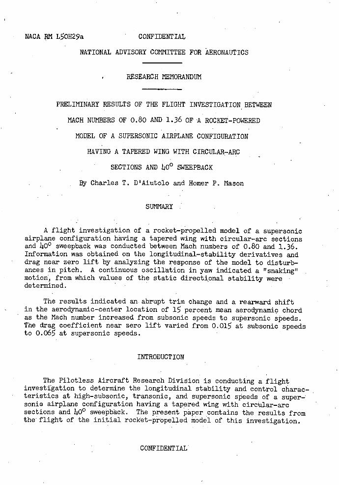
(o14 Copy RM L501129a
NACA
RESEARCH MEMORANDUM PRELIMINARY RESULTS OF THE FLIGHT INVESTIGATION BETWEEN
MACH NUMBERS OF 0.80 AND 1,36 OF A ROCKET-POWERED
MODEL OF A SUPERSONIC AIRPLANE CONFIGURATION
HAVING A TAPERED WING WITH CIRCULAR-ARC in
SECTIONS AND 40 0 SWEEPEACK
By Charles T. D'Aiutolo and Homer P. Masoncy 0
All Langley Aeronautical Laboratory
Langley Air Force Base, Va. Ca,
'ii I his document contains classifiedintortnolion affecting the National Defense of the United States witr.ln the
mooning of the Espionage Act, USC 50:31and hi. Its transmission or the revelation of Its contents In any in to an unasthorized person Is prohibited by law. Information on classified may be Imported only to persons in the military and naval services of the United
Stales, appropriate civilian officers and employees of the Federal Government who have a legitimate Interest therein
and to United States citizens of known loyalty and discretion who f necessity moot be lotortated thereof.
NATIONAL ADVISORY COMMITTEE FOR AERONAUTICS
WASHINGTON
C. NilDENY1AL°
,iJSSIFF C D ICU 1StaNT
https://ntrs.nasa.gov/search.jsp?R=19930086386 2018-06-01T14:39:42+00:00Z
MACA RM L50H29a CONFIDENTIAL
NATIONAL ADVISORY COMMITTEE FOR AERONAUTICS
RESEARCH MEMORANDUM
PRELIMINARY RESULTS OF THE FLIGHT INVESTIGATION BETWEEN
MACH NUMBERS OF 0.80 AND 1.36 OF A ROCKET-POWERED
MODEL OF A SUPERSONIC AIRPLANE CONFIGURATION
HAVING A TAPERED WING WITH CIRCULAR-ARC
SECTIONS AND LiO° SWEEPBACK
By Charles T. D'Aiutolo and Homer P. Mason
SUMMARY
A flight investigation of a rocket-propelled model of a supersonic airplane configuration having a tapered wing with circular-arc sections and 400 sweepback was conducted between Mach numbers of 0.80 and 1.36. Information was obtained on the longitudinal-stability derivatives and drag near zero lift by analyzing the response of the model to disturb-ances in pitch. A continuous oscillation in yaw indicated a snaking" motion, from which values of the static directional stability were determined.
The results indicated an abrupt trim change and a rearward shift in the aerodynamic-center location of 15 percent mean aerodynamic chord as the Mach number increased from subsonic speeds to supersonic speeds. The drag coefficient near zero lift varied from 0.015 at subsonic speeds to 0.065 at supersonic speeds.
INTRODUCTION
The Pilotless Aircraft Research Division is conducting a flight investigation to determine the longitudinal stability and control charac-teristics at high-subsonic, transonic, and supersonic speeds of a super-sonic airplane configuration having a tapered wing with circular-arc sections and 1400 sweepback. The present paper contains the results from the flight of the initial rocket-propelled thodel of this investigation.
CONFIDENTIAL
2 CONFIDENTIAL NACA RN L0H29a
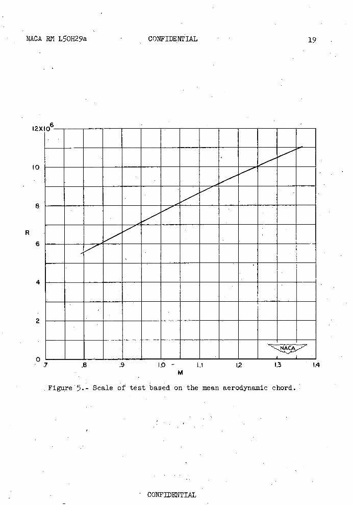
The Mach number range covered in the present test was from. 0.8 to 1.36
corresponding to a Reynolds number range of 5.6 x 10⁶ to 11-05 x 106, respectively.
Stability derivatives and drag characteristics were determined by the rocket-propelled model technique for fixed control when the model was disturbed in pitch by a series of small rocket motors mounted to provide thrust normal to the longitudinal axis of the model. The model was flown at the Langley Pilotless Aircraft Research Station at Wallops Island, Va.
SYMBOLS
t one-half thickness of airfoil at aileron hinge line
R Reynolds number (based on the mean aerodynamic chord of the wing)
mean aerodynamic chord, feet (1.22 ft)
c chord, feet
V velocity, feet per second
N Mach number
CL lift coefficient
a angle of attack of the body, degrees
dCL C -, per degree
da.
P period of an oscillation in pitch, seconds
Cm pitching-moment coefficient
dCper degree
ma a
Xa.c. distance from leading edge of mean aerodynamic chord to aerodynamic center of airplane, percent of mean aerodynamic chord, positive rearward
CONFIDENTIAL
NACA RN L0H29a CONFIDENTIAL 3
T1/2 time to damp to one-half amplitude, seconds
ac C mq -r- per degree
IC 2V
ac C . --, per degree
2V
ê_de dt
0 angle of pitch, degrees
da
dt
I moment of inertia in pitch, slug-f eet2
CDCdrag coefficient near zero lift L
period of an oscillation in yaw, seconds
C 1 damping in roll
paCn Cn per degree
angle of sideslip, degrees
Cn yawing-moment coefficient
Wanfrequency of an oscillation in normal accelerometer, cycles
per second
MODEL AND APPARATUS
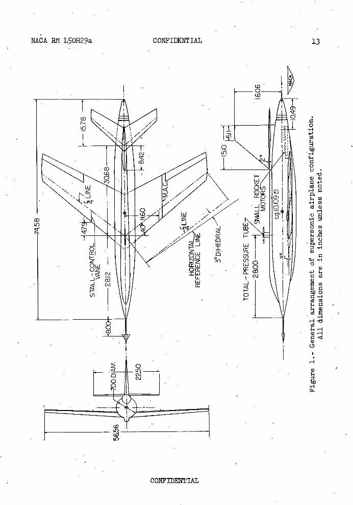
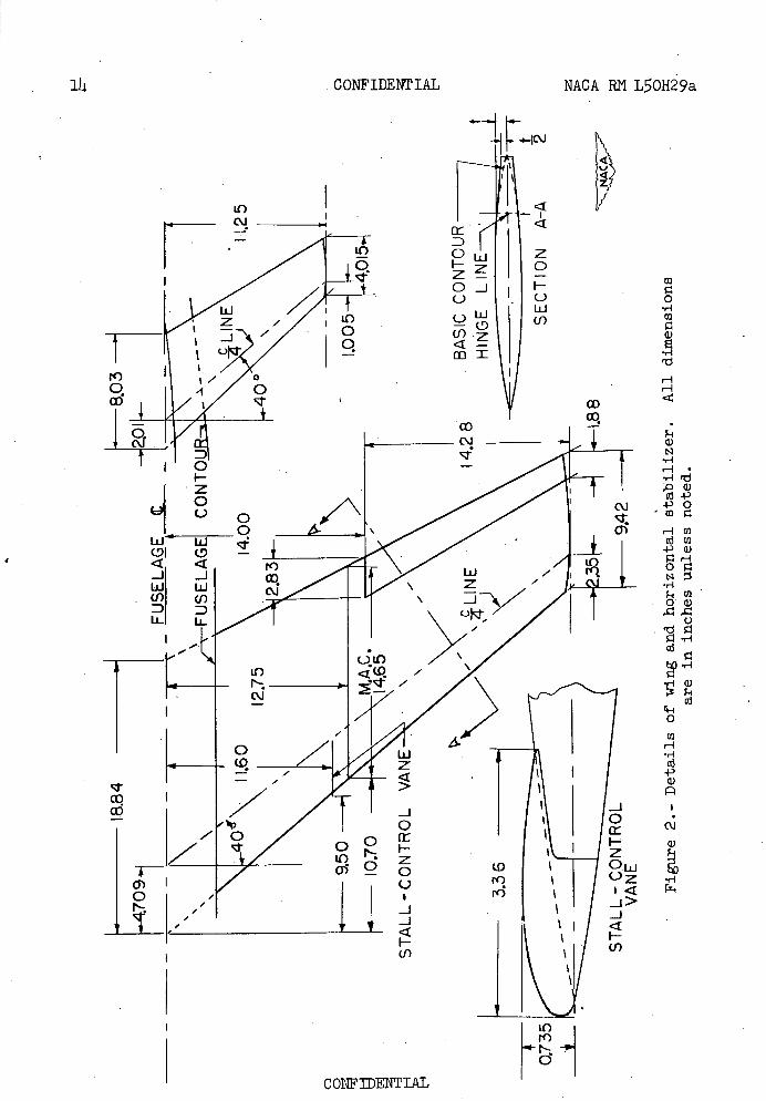
The general arrangement of the model and details of wing and tail are shown in figures 1 and 2, respectively, and the geometric charac-teristics of the model are given in table I. Photographs of the model
CONFIDENTIAL
CONFIDENTIAL NACA R1'1 L0829a
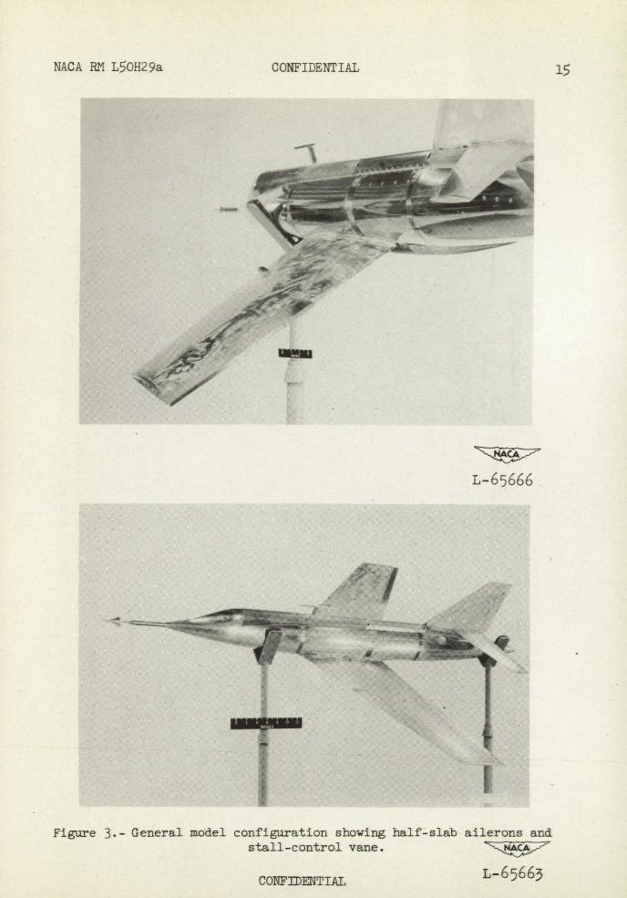
are shown in figure 3, and a photograph of the model and booster combi-nation is shown in figure ). The model fuselage was a body of revolution of fineness ratio 9.8, containing a cylindrical center section, ogival nose and tail sections, and dorsal and ventral canopies. Construction of the fuselage was principally of duraluminum with magnesium skin. The nose section contained the telemeter; the center section contained the power section and wing mount; and the tail section contained three small rocket motors.
The wing of the model was made of steel and had 10-percent circular-arc airfoil sections perpendicular to the quarter-chord line and incor-porated asweepback of 400 at the quarter-chord line.
The wing was modified to simulate one-half-slab rigid ailerons of 2-percent span with 00 deflection.
The horizontal tail was similar to the wing in plan form but had NACA 6-008 airfoil sections and was constructed principally of wood with a metal inlay.
The model contained a six-channel telemeter; measurements were made of the normal, longitudinal, and transverse acceleration, angle of attack, total pressure, and static pressure. The angle of attack was measured by a vane-type instrument located on a sting forward of the nose of the model as described in reference 1. A static-pressure orifice was located in the base of this instrument, and a total-pressure tube was located on a small strut above the fuselage.
Additional velocity data were obtained by CW Doppler radar; range and elevation of the model during flight, by tracking radar; atmospheric conditions, by a radisonde; the first portion of the flight was recorded by high-speed cameras.
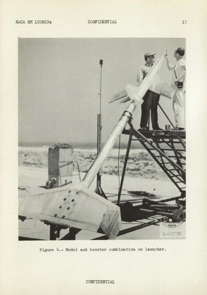
The model contained no sustainer rocket motor but was boosted to a Mach number of 1.36 by an ABL Deacon rocket motor. Upon burnout of this rocket motor, the model separated from the booster and coasted through the test speed range.
The booster-model combination was launched from a crutch-type launcher at an angle of 460, as shown in figure ti.
The wing was set at 30 incidence, and the deflection of the hori-zontal tail was set at 20 relative to the fuselage center line so that' the model would have reasonable trim values as estimated by using the data from references 2 and 3. -
CONFIDENTIAL
NACA RN L50H29a CONFIDENTIAL 5
Test Technique
The model was disturbed in pitch by three small rocket motors providing thrust normal to the longitudinal axis of the model and located in the tail of the model, as shown in figure 1. The firing sequence of these rocket motors was such that the oscillation caused by the firing of the first small rocket would damp to an approximate trim angle of attack bef.ore the second rocket motor was fired. Each of these rocket motors caused the model to oscillate in pitch and the desired longitudinal-stability parameters were obtained from the oscil-lations of the angle of attack and from the normal acceleration traces.
An oscillatory motion of the.trace of the transverse accelerometer was present throughout the test Mach number'range and gave information on the static directional stability.
The scale of the test is presented in figure 5 by a plot of Reynolds number against Mach number; the Reynolds number is based on the mean aerodynamic chord of the wing.
RESULTS AND DISCUSSION
The method of reducing the data and the accuracy of the results presented herein are described in detail in appendix A of reference Li..
All of the stability parameters presented in this paper are for a center-of-gravity position of 10.9 percent of the mean aerodynamic chord of the wing, a fixed angle of 2 0 of the horizontal tail, and lift coef-ficients near zero. Roll data (not presented in this report) indicated a very low rate of roll; hence, the stability derivatives were considered to be unaffected by roll in this test.
Although the model was disturbed in pitch by small rocket motors, the record of the flight test indicated five distihct oscillations. At the time of separation of model and booster, the model pitched up abruptly and oscillated until it damped to a steady trim angle of attack. The second oscillation was due to the firing of the first small rocket motor. When passing through the transonic range, the model was disturbed because of an abrupt trim change. The resulting oscillation started at about a Mach number of 0.99 and continued to a Mach number of about 0.96. The fourth and fifth oscillations were due to the firing of the second and third small rocket motors.
CONFIDENTIAL
6 CONFIDENTIAL NACA RN L0H29a
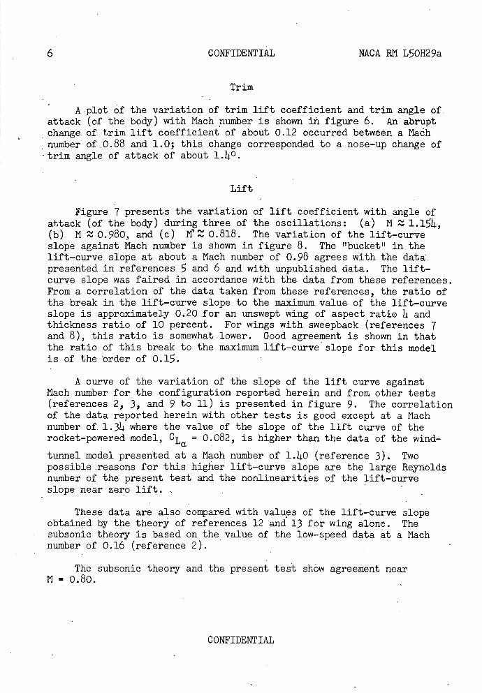
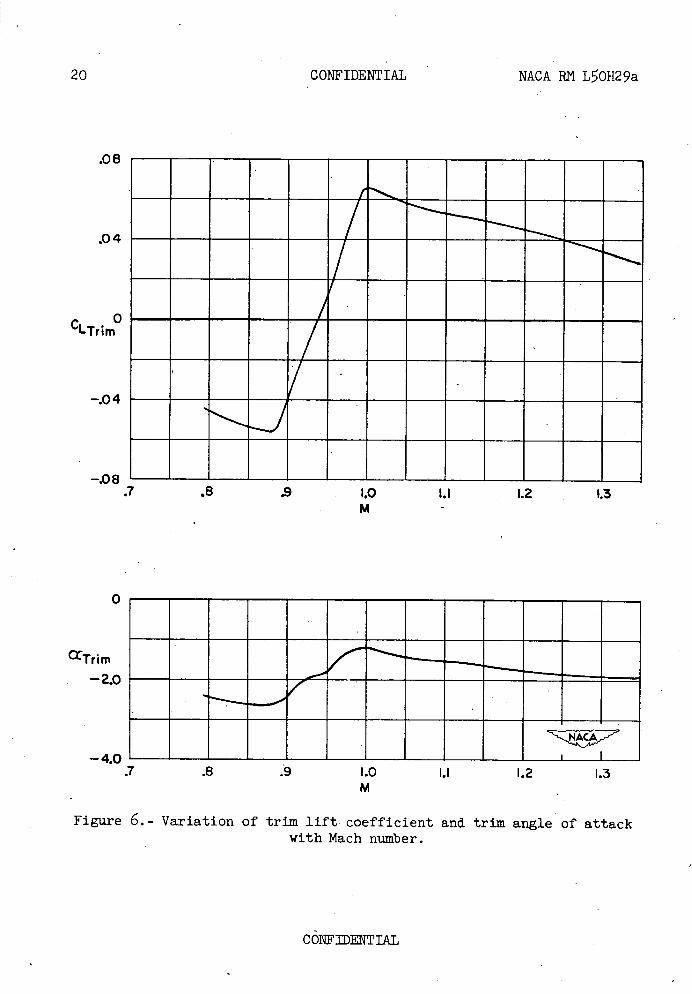
Trim
A plot of the variation of trim lift coefficient and trim angle of. attack (of the body) with Mach number is shown in figure 6. An abrupt change of trim lift coefficient of about 0.12 occurred between a Mach number of 0.88 and 1.0; this change corresponded to a nose-up change of trim angle of attack of about 1.140.
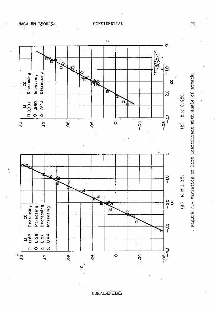
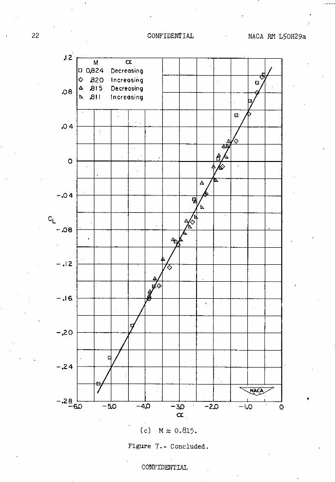
Lift
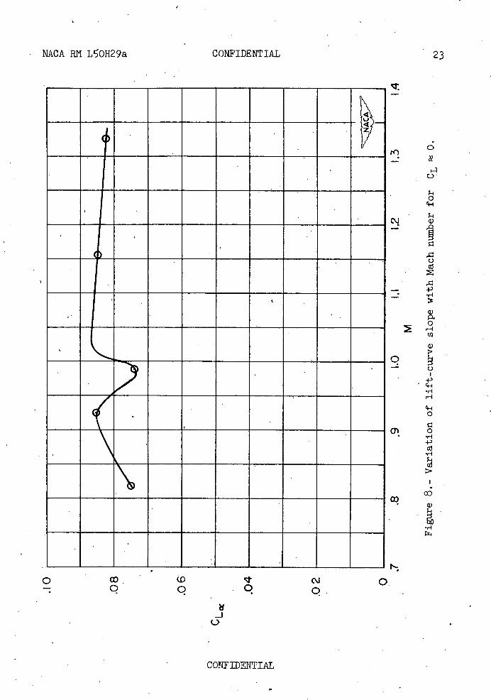
Figure 7 presents the variation of lift coefficient with angle of attack (of the body) during three of the oscillations: (a) N Z 1.154, (b) N 0.980, and (c) M 0.818. The variation of the lift-curve slope against Mach number is shown in figure 8. The "bucket" in the lift-curve slope at about a Mach number of 0.98 agrees with the data presented in references 5 and 6 and with unpublished data. The lift-curve slope was faired in accordance with the data from these references. From a correlation of the data taken from these references, the ratio of the break in the lift-curve slope to the maximum value of the lift-curve slope is approximately 0.20 for an unswept wing of aspect ratio 4 and thickness ratio of 10 percent. For wings with sweepback (references 7 and 8), this ratio is somewhat lower. Good agreement is shown in that the ratio of this break to the maximum lift-curve slope for this model is of the order of 0.15.
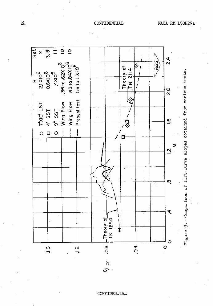
A curve of the variation of the slope of the lift curve against Mach number for the configuration reported herein and from other tests (references 2, 3, and 9 to 11) is presented in figure 9. The correlation of the data reported herein with other tests is good except at a Mach number of 1.314 where the value of the slope of the lift curve of the rocket-powered model, CL = 0.082, is higher than the data of the wind-
tunnel model presented at a Mach number of 1.140 (reference 3). Two possible .reasons for this higher lift-curve slope are the large Reynolds number of the present test and the nonlinearities of the lift-curve slope near zero lift.
These data are also compared with values of the lift-curve slope obtained by the theory of references 12 and 13 for wing alone. The subsonic theory is based on the value of the low-speed data at a Mach number of 0.16 (reference 2).
The subsonic theory and the present test show agreement near N = 0.80. .
CONFIDENTIAL
NACA RN L0R29a CONFIDENTIAL 7
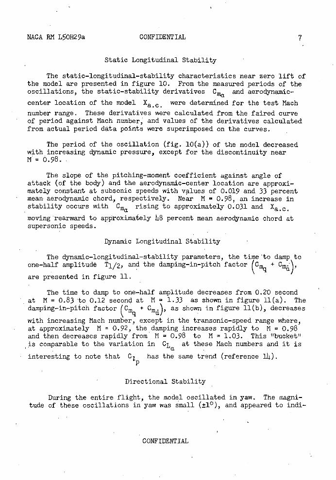
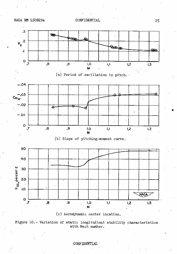
Static Longitudinal Stability
The static-longitudinal-stability characteristics near zero lift of the model are presented in figure 10. From the measured periods of the oscillations, the static-stability derivatives C and aerodynamic-ma center location of the model Xa.c. were determined for the test Mach
number range. These derivatives were calculated from the faired curve of period against Mach number, and values of the derivatives calculated from actual period data points were superimposed on the curves.
The period of the oscillation (fig. 10(a)) of the model decreased with increasing dynamic pressure, except for the discontinuity near N= 0.98.
The slope of the pitching-moment coefficient against angle of attack (of the body) and the aerodynamic-center location are approxi-mately constant at subsonic speeds with values of 0.019 and 33 percent mean aerodynamic chord, respectively. Near N = 0.98, an increase in stability occurs with C rising to approximately 0.031 and Xa.c. moving rearward to approximately 48 percent mean aerodynamic chord at supersonic speeds.
Dynamic Longitudinal Stability
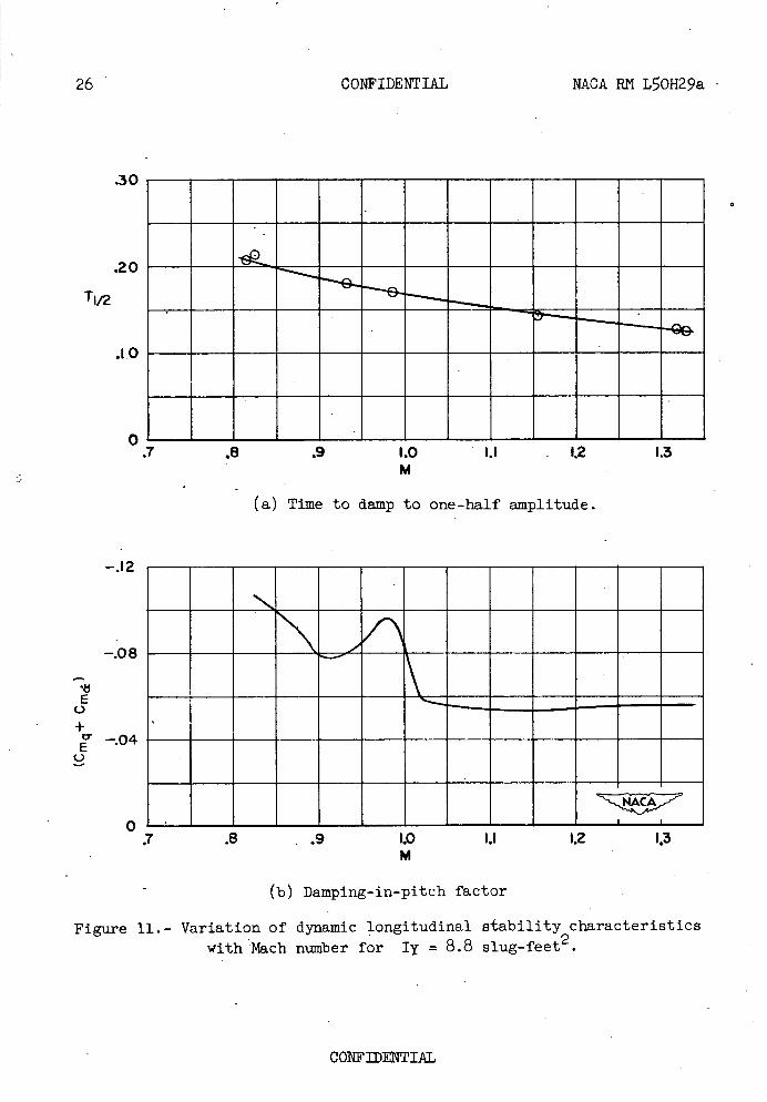
The dynamic-longitudinal-stability parameters, the time to damp to one-half amplitude T1/2, and the damping-in-pitch factor ( Cmq + C%)' are presented in figure 11.
The time to damp to one-half amplitude decreases from 0.20 second at N = 0.83 to 0.12 second at N = 1.33 as shown in figure 11(a). The damping-in-pitch factor(C + Cm.) as shown in figure 11(b), decreases
cc with increasing Mach number, except in the transonic-speed range where, at approximately N = 0.92, the damping increases rapidly to N = 0.98 and then decreases rapidly from N = 0.98 to N = 1.03. This "bucket" is comparable to the variation in CL at these Mach numbers and it is
interesting to note that C1 p
has the same trend (reference lL).
Directional Stability
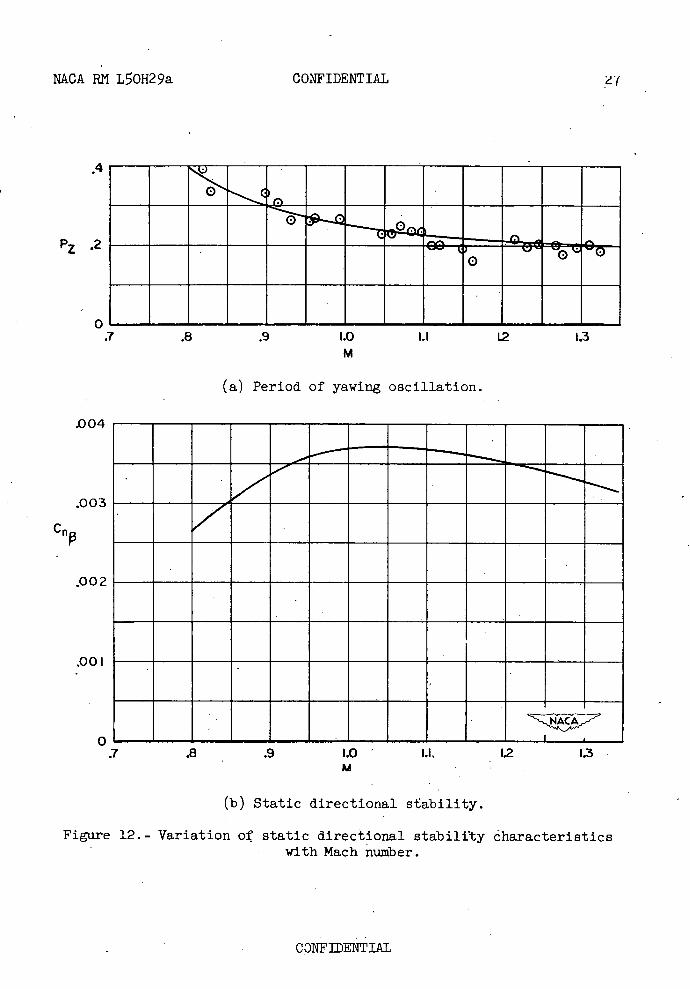
During the entire flight, the model oscillated in yaw. The magni-tude of these oscillations in yaw was small (±10 ), and appeared to mdi-
CONFIDENTIAL
8 CONFIDENTIAL NACA RN LOH29a
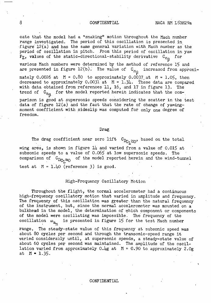
cate that the model had a snaking" motion throughout the Mach number range investigated. The period of this oscillation is presented in figure 12(a) and has the same general variation with Mach number as the period of oscillation in pitch. From this period of oscillation in yaw PZ, values of the static-directional-stability derivative Cn for
various Mach numbers were determined by the method of reference 15 and are presented in figure 12(b). The value of Crj increased from approxi-
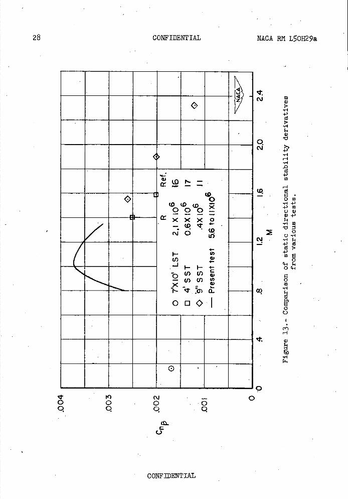
mately 0.0026 at N = 0.80 to approximately 0.0037,at N = 1.0, then decreased to approximately 0.0031 at N = 1.314. These data are compared with data obtained from references 11, 16, and 17 in figure 13. The trend of Crj for the model reported herein indicates that the corn-•
parison is good at supersonic speeds considering the scatter in the test data of figure 12(a) and the fact that the rate of change of yawing-moment coefficient with sideslip was computed for only one degree of freedom.
Drag
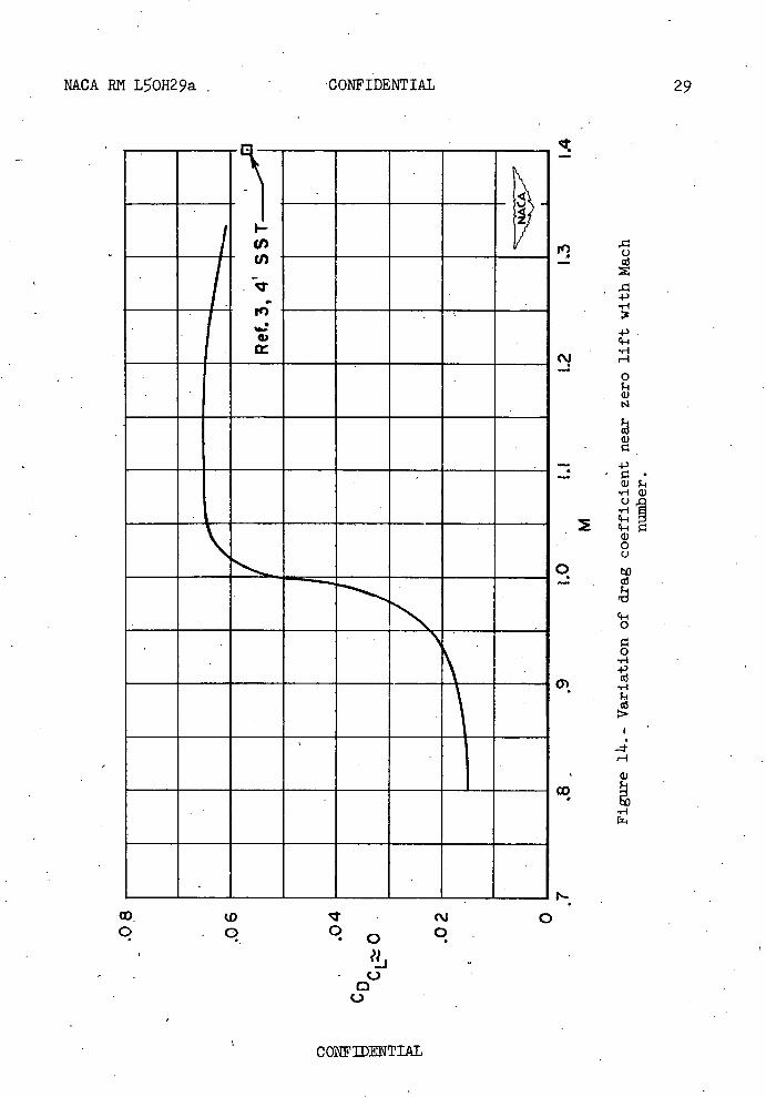
The drag coefficient near zero lift CDC, based on the total
wing area, is shown in figure 114 and varied from a value of 0.015 at subsonic speeds to a value of 0.06 at low supersonic speeds. The comparison of CDC ..,. of the model reported herein and the wind-tunnel
LO test at N = 1.140 (reference 3) is good.
High-Frequency Oscillatory Notion
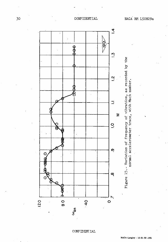
Throughout the flight, the normal accelerometer had a continuous high-frequency oscillatory motion that varied in amplitude and frequency. The frequency of this oscillation was greater than the natural frequency of the instrument, but, since the normal accelerometer was mounted.on a bulkhead in the model, the determination of which component or components of the model were oscillating was impossible. The frequency of the oscillation co is presented in figure 15 for the test Mach number
I an range. The steady-state value of this frequency at subsonic speed was about 80 cycles per second and through the transonic-speed range it varied considerably until, at supersonic speeds, a steady-state value of about 60 cycles per second was maintained. The amplitude of the oscil-lation varied from approximately O.14g at N = 0.90 to approximately 2.Og at M=1.3.
CONFIDENTIAL
NACA RN L50H29a CONFIDENTIAL 9
CONCLUSIONS
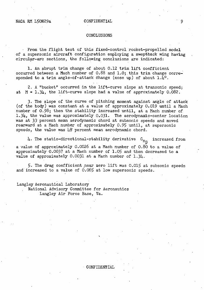
From the flight test of this fixed-control rocket-propelled model of a supersonic aircraft configuration employing a sweptback wing having circular-arô sections, the following conclusions are indicated:
1. An abrupt trim change of about 0.12 trim lift coefficient occurred between a Mach number of 0.88 and 1.0; this trim change corre-sponded to a trim angle-of-attaák óhange (nose up) of about i.li°.
2. A"bucket" occurred in the lift-curve slope at transonic speed; at N = 1.34, the lift-curve slope had a value of approximately 0.082.
3. The slope of the curve of pitching moment against angle of attack (of the body) was constant at a value of approximately 0.019 until a Mach number of 0.98; then the stability increased until, at a Mach number of 1.34, the value was approximately 0.031. The aerodynamic-center location was at 33 percent mean aerodynamic chord at subsonic speeds and moved rearward at a Mach number of approximately 0.95 until, at supersonic speeds, the value was I8 percent mean aerodynamic chord.
4. The static-directional-stability derivative Cn increased from
a value of approximately 0.0026 at a Mach number of 0.80 to a value of approximately 0.0037 at a Mach number of 1.0 and then decreased to a value of approximately 0.0031 at a Mach number of 1.34.
. The drag coefficient near zero lift was 0.015 at subsonic speeds and increased to a value of 0.06 at low supersonic speeds.
Langley Aeronautical Laboratory National Advisory Committee for Aeronautics
Langley Air Force Base, Va.
CONFIDENTIAL
10 CONFIDENTIAL MACA RN L50H29a
REFERENCES
1. Mitchell, Jesse L., and Peck, Robert F.: An NACA Vane-Type Angle-of-Attack Indicator for Use at Subsonic and Supersonic Speeds. MACA RN L9F28a, 1949.
2. Weil, Joseph, Comisarow, Paul, and Goodson, Kenneth W.: Longitudinal Stability and Control Characteristics of an Airplane Model Having a 42.80 Sweptback Circular-Arc Wing with Aspect Ratio 4.00, Taper Ratio 0.50, and Sweptback Tail Surface. MACARM L7G28, 1947.
3. Spearman, N. Leroy: An Investigation of a SVpersonic Aircraft Configuration Having a Tapered Wing with Circular-Arc Sections and 400 Sweepback.. Static Longitudinal Stability and Control Characteristics at a Mach Number of 1.40. NACA RN L9L08, 1950.
4. Gulls, Clarence L., Peck, Robert F., and Vitale, A. James: Pre-liminary Results from a Free-Flight Investigation at Transonic and Supersonic Speeds of the Longitudinal Stability and Control Charac-teristics of an Airplane Configuration with a Thin Straight Wing of Aspect Ratio 3. NACA RN L9K25a, 1950.
5. Goodson, Kenneth W., and Morrison, William D., Jr.: Aerodynamic Characteristics of a Wing with Unswept Quarter-Chord Line, Aspect Ratio 4, Taper Ratio 0.6, and NACA 65A006 Airfoil Section. Transonic-Bump Method. NACA RN L9H22, 1949.
6. Myers, Boyd C., II, and Wiggins, James W.: Aerodynamic Characteristics of a Wing with Unswept Quarter-Chord Line, Aspect Ratio 4, Taper Ratio 0.6, and NACA 65A004 Airfoil Section. Transonic-Bump Method. NACA RN L5OC16, 1950.
7. Sleeman, William C., Jr., and Becht, Robert E.: Aerodynamic. Charac-teristics of a Wing with Quarter-Chord Line Swept Back 35 0 ; Aspect Ratio 4, Taper Ratio 0.6, and NACA 65A006 Airfoil Section. Transonic-Bump Method. NACA RN L9B25, 1949.
8. King, Thomas J., Jr., and Myers, Boyd C., II: Aerodynamic Charac-teristics of a Wing with Quarter-Chord Line Swept Back 600 5 Aspect Ratio 4, Taper Ratio 0.6, and NACA 65A006 Airfoil Section. Transonic-Bump Method. NACA RN L9G27, 1949.
9. Spearman, N. Leroy, and Hilton, John H., Jr.: An Investigation of a Supersonic Aircraft Configuration Having a Tapered Wing.with Circular-Arc Sections and 40 0 Sweepback. Static Longitudinal Stability and Control Characteristics at a Mach Number of 1.59. MACA RN L50EI2 3 1950.
CONFIDENTIAL
NACA RN L0H29a CONFIDENTIAL 11
10. Crane, Harold-L., and Adams, James J.: Wing-Flow Measurements of Longitudinal Stability and Control Characteristics of a Supersonic Airplane Configuration Having a 42.8 0 Sweptback Circular-Arc Wing with Aspect Ratio 4.0, Taper Ratio 0.50, and Sweptback Tail Surfaces. NACA RN L0B09, 190.
lt. Ellis, Macon C., Jr., Hasel, Lowell E., and Grigsby, Carl E.: Supersonic-Tunnel Tests of Two Supersonic Airplane Model Configu-rations. NACA RN L7Jl, 1947.
12. Fisher, Lewis R.: Approximate Corrections for the Effects of Com-pressibility on the Subsonic Stability Derivatives of Swept Wings. NACA TN 184 5 1949.
13. Harmon, Sidney N., and Jeffreys, Isabella: Theoretical Lift and Damping in Roll of Thin Wings with Arbitrary Sweep and Taper at Supersonic Speeds. Supersonic Leading and Trailing Edges. NACA TN 2114, 190.
14. Lockwood, Vernard E.: Damping-in-Roll Characteristics of a Sweptback Wing as Determined from a Wind-Tunnel Investigation of a Twisted Semispan Wing. NACA RN L9F1, 1949.
1. Bishop, Robert C., and Lomax, Harvard: A Simplified Method for Determining from Flight Data the Rate of Change of Yawing-Moment Coefficient with Sideslip. NACA TN 1076 5 1946.
16. Goodson, Kenneth W., and Comisarow, Paul: Lateral Stability and Control Characteristics of an Airplane Model Having a 42.8 0 Swept-back Circular-Arc Wing with Aspect Ratio 4.00, Taper Ratio 0.0, and Sweptback Tail Surfaces. NACA RN L7G31, 1947.
17. Spearman, N. Leroy: An Investigation of a Supersonic Aircraft Configuration Having a Tapered Wing with Circular-Arc Sections and 400 Sweepback. Static Lateral Stability Characteristics at Mach Numbers of 1.40 and 1.9. NACA RN L0C17, 190.
CONFIDENTIAL
12 . CONFIDENTIAL NACA RM L0}{29a
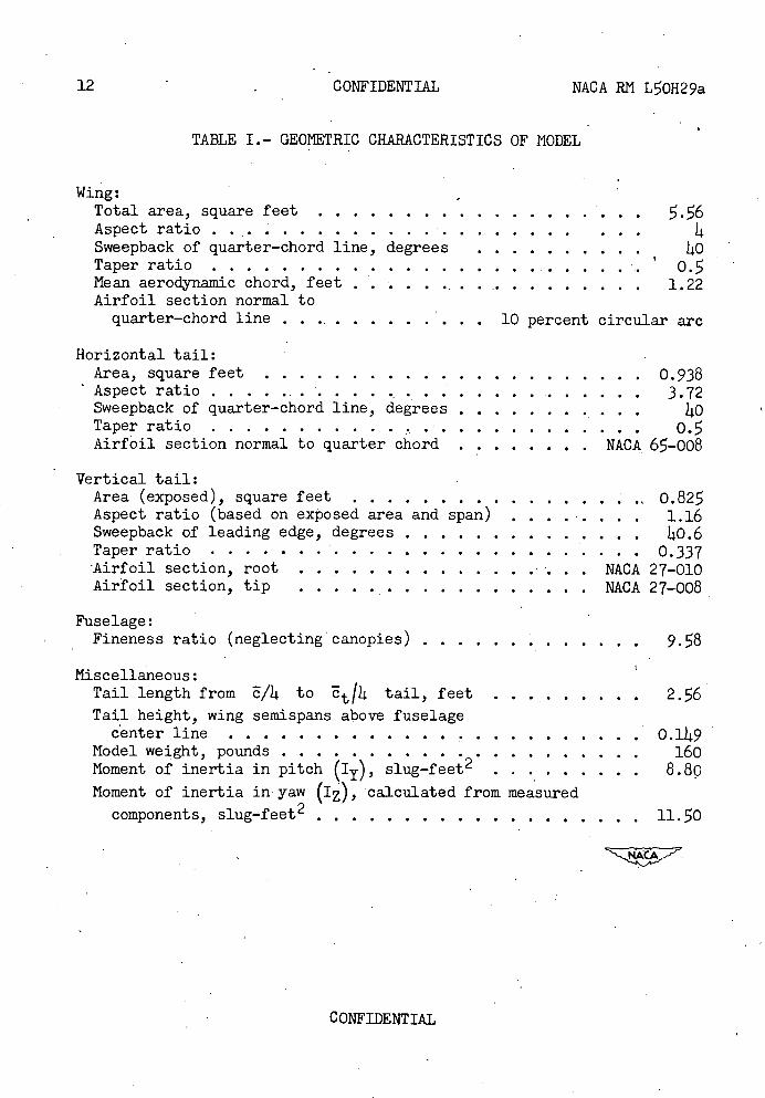
TABLE I.- GEOMETRIC CHARACTERISTICS OF MODEL
Wing: Total area, square feet Aspect ratio ....................... . . Sweepback of quarter-chord line, degrees ..........to Taper ratio ........................... Mean aerodynamic chord, feet .....................1.22 Airfoil section normal to quarter-chord line ..............10 percent circular are
Horizontal tail: Area, square feet .......................0.938 Aspectratio.............................3.72 Sweepback of quarter-chord line, degrees ...........ItO Taper ratio ........................... o. Airfoil section normal to quarter chord ........NACA 65-008
Vertical tail: Area (exposed), square feet ...................o.82 Aspect ratio (based on exposed area and span) .........1.16 Sweepback of leading edge, degrees ..............Ito.6 Taper ratio ..........................0.337 Airfoil section, root .............. ... . . NACA 27-010 Airfoil section, tip .... ... ........... NACA 27-008
Fuselage: Fineness ratio (neglecting canopies) .............9.8
Miscellaneous: Tail length from /L to tail, feet .........2.6 Tail height, wing semispans above fuselage center line ........................O.1It9
Model weight, pounds .....................160 Moment of inertia in pitch (Iy), slug-feet 2 .........8.8o
Moment of inertia in yaw (Ia), calculated from measured
components, slug-feet2 ...................11.O
CONFIDENTIAL
LII I
Ll
H II LU II
II o ii Oct IR. Q0 Ik I— 110
II 11q 1101
LU Cl)
ID
LU cr D o Cr)
LLJ Qo cli
0 I-
0
ci 4.)
0 0
0)0)
50 P1
H 0
.-1 ow
0)0
0a)
4.)
Cc w
Q)H 0)
H cu
MACA RN L0H29a CONFIDENTIAL
13
1<2
V
03
0 r1 03
a)
H H
a) 1 t1
H. .fl (.j +)0
cd
ci-O) H03
I +Q)
L .0 • a)
cd
C)
r4
r-1a)
cs-I
0
cd
03
H rI
a)
_i I
0 C')
F-z old UZ 1< 4
-I> -J
H U,
fl CONFIDENTIAL NACA RJ"I L5QH29a.
^—^w
to
__ ___
•
• oWIz o0_i H
WV V
LLJ
z / if) •c? T- -1 /
ot coi\Ii
I I
0 0 i() 0 o 0 OD
co
II 0 H
0
01 (D
jI -J 00LLJ
WI W
T
• U)I (I, Di D
LL LLI
if)
_; OD
0 0 0 0 V
0•' I I o N- / I cf //
- 4 (I •
H (I)
Ito I)
COI1FEENTIAI
NACA RN L0H29a CONFIDENTIAL
L-65666
Figure 3.- General model configuration showing half-slab ailerons and stall-control vane.
coirii, L-65663
I
I
N4ACA
NACA RN LOH29a CONFIDENTIAL 17
CONFIDENTIAL
NACA R?I L0H29a CONFIDENTIAL 19
12 X io6
I
8
R
6
4
2
rs7 .8 .9 1.0 - 1.1 12 13 1.4
M
Figure 5.- Scale of test based on the mean aerodynamic chord.
CONFIDENTIAL
20 CONFIDENTIAL NACA RN L0H29a
.08
.04
0 CLTrim
—.04
—.08 '-.7 .8 .9 1.0 1.1 1.2 1.3
M -
Trim
—2.0
.7 .8 .9 1.0 LI 1.2 1.3 M
Figure 6.- Variation of trim lift coefficient and trim angle of attack with Mach number.
CONFIDENTIAL
c
", --- .
U U a, a,
0
OD OD —
D1
0
C) U a5 U
4)
0• ril Q o\ '1)
ri o
cd 22
MACA RN L50H29a CONFIDENTIAL 21
(D cd CD 0 0• q
I- co _-
a) 0
4-4 cs—I
a) 0
NIA
---- --
C3 a
UU 0
o q
WI 0
L)
4—I r1
H
4-4 0
0
H 0
Hcx
cd
22 •r-I
0
0.
ID c'j OD 0 —; - 0 0 0•
-j 0
CONFIDENTIAL
M 0 0.824 Decreasing
.820 Increasing
.815 Decreasing
.811 Increasing
-
a
IIIIIIIIII
ell,
---/-
GL IIIIIIII I
22
.2
.08
.04
0
-.04
CL
-.08
—.12
-.20
-.24
CONFIDENTIAL
NACA RN L0H29a
—4.0 —3.0 —2.0 —LO cc
(c) M 0.815.
Figure . - Concluded.
CONFIDENTIAL
NACA RI'1 L50H29a
CONFIDENTIAL
23
c
0 c-I
11
::
j
a)
2+)
H
c-I
0
0
co
N
0 OD (D c'J 0. —: 2 2 Q.
—J • U
• CONFIDENTIAL
N
0. ('J
c'J
CD
CD '1) +
CD
0
rd
"-I
a)
r4 "3
4)
co a)
0 H
CD
4-3
I
24 CONFIDENTIAL NACA RN L0H29a
cu N cr • N
Q(O
-
I -L<\ - 2 Oq' I
-V. - I crxX c co - (C?. . 4- _C Z
0 CD r) ) rci5
I—Il-
4-I—(I) o
-
/
/
x /J
P -,
\ ,'
U-,)
0 cu
I—I-
co
- . 0
0
-J 0
•0
0
CONFIDENTIAL
NACA RN L50H29a
CONFIDENTIAL
2
.3
.2 PY
0.7 .8 .9 1.0 1,1 12 1,3
M
(a) Period of oscillation in pitch.
-.04
—.03 Cm
—.02
-.01
0.7 .8 .9 1.0 1.1 1.2 1.3
M
(b) Slope of pitching-moment curve.
50
40
lu
tO
0 - .7 .8 .9 1.0 1.1 1.2 1.3
M
(c) Aerodynamic center location.
Figure 10.- Variation of static longitudinal stability characteristics with Mach number.
CONFIDENTIAL
26 CONFIDENTIAL NACA RN L50H29a
.30
.20
.1.0
0.7
—.12
—.08
.3 E
C-)
+Cr —.04
0
A
.8 .9 1.0 1.1 12 1.3 N
(a) Time to damp to one-half amplitude.
.7 .8 . .9 1.0 1.1 1.2 1,3 M
(b) Damping-in-pitch factor
Figure 11.- Variation of dynamic longitudinal stability characteristics
with Mach number for ly = 8.8 slug-feet2.
CONFIDENTIAL
NACA RN L50H29a CONFIDENTIAL
.4
I P .2
I
0
I
.7 .8 .9 1.0 1.1 12 M
(a)Period of yawing oscillation.
.004
.003
cflp
.002
0.7 .8 .9 1.0 1.1, 12 1.3
M
(b)Static directional stability.
Figure 12. - Variation of static directional stability characteristics with Mach number.
CONFIDENTIAL
to cj - 0 0 0 0 Q Q q Q
4
G
(00 G
I
—
000-
/U)
-
ooOI
0
c'J
'-I +
•rl
U)
0 ci
H '-I
4) a)
(0 -
ow 4)
u
a)
0 U •-i
('.1. •,-
cd 4-)
0
oq-1
r. 0
ft 0 0
H
U)
C-)
28 CONFIDENTIAL NACA RII L50H29a
CONFIDENTIAL
OD (D
q
('J
0
0.0
0
- C)
U
CONFIDENTIAL
MACA RN L0H29a CONFIDENTIAL 29
ro 0
4.)
H
H H
0
C) N
C)
4)
•r-1 C)
H cl—I
C) 0 0
0
0
r. 0 H 4-) "5
H
cd
-; H
30
CONFIDENTIAL
NACA RN L0H29a
I
CONFIDENTIAL
ne
O k4Q
I)
'1)
Id
Id
cJ cl)Q)
0 -
• +
'H •-I
ocd
0•
)Q)
OH Q)
0:)4)
cd
cq
0 0 CD
C 0
3
0 ('J
NACA-Langley - 10-31-50 -376