Embed Size (px)
Citation preview
NAVAL
POSTGRADUATE
SCHOOL
MONTEREY, CALIFORNIA
THESIS
Approved for public release; distribution is unlimited
CLOUD COMPUTING SOLUTIONS FOR THE MARINE
CORPS: AN ARCHITECTURE TO SUPPORT
EXPEDITIONARY LOGISTICS
by
Charles R. Ibatuan II
September 2013
Thesis Advisor: Dan Boger
Co-Advisor Albert Barreto

THIS PAGE INTENTIONALLY LEFT BLANK
i
REPORT DOCUMENTATION PAGE Form Approved OMB No. 0704-0188 Public reporting burden for this collection of information is estimated to average 1 hour per response, including the time for reviewing instruction,
searching existing data sources, gathering and maintaining the data needed, and completing and reviewing the collection of information. Send
comments regarding this burden estimate or any other aspect of this collection of information, including suggestions for reducing this burden, to Washington headquarters Services, Directorate for Information Operations and Reports, 1215 Jefferson Davis Highway, Suite 1204, Arlington, VA
22202-4302, and to the Office of Management and Budget, Paperwork Reduction Project (0704-0188) Washington DC 20503.
1. AGENCY USE ONLY (Leave blank)
2. REPORT DATE September 2013
3. REPORT TYPE AND DATES COVERED Master’s Thesis
4. TITLE AND SUBTITLE
CLOUD COMPUTING SOLUTIONS FOR THE MARINE CORPS: AN
ARCHITECTURE TO SUPPORT EXPEDITIONARY LOGISTICS
5. FUNDING NUMBERS
6. AUTHOR(S) Charles R. Ibatuan II
7. PERFORMING ORGANIZATION NAME(S) AND ADDRESS(ES)
Naval Postgraduate School
Monterey, CA 93943-5000
8. PERFORMING ORGANIZATION
REPORT NUMBER
9. SPONSORING /MONITORING AGENCY NAME(S) AND ADDRESS(ES)
Installation and Logistics Department, HQMC
Washington, DC 20350-3000
10. SPONSORING/MONITORING
AGENCY REPORT NUMBER
11. SUPPLEMENTARY NOTES The views expressed in this thesis are those of the author and do not reflect the official policy
or position of the Department of Defense or the U.S. Government. IRB Protocol number ____N/A____.
12a. DISTRIBUTION / AVAILABILITY STATEMENT Approved for public release;distribution is unlimited
12b. DISTRIBUTION CODE
13. ABSTRACT (maximum 200 words)
The Department of Defense (DoD) is planning an aggressive move toward cloud computing technologies. This concept has been
floating around the private information technology sector for a number of years and has benefited organizations with cost savings,
increased efficiencies, and flexibility by sharing computer resources through networked connections. The push for cloud
computing has been driven by the 25 Point Implementation Plan to Reform Federal Information Technology Management that
highlighted the shift to a cloud first policy. The cloud first policy has driven the DoD, specifically the Marine Corps, toward cloud
computing technologies making this relatively new paradigm inevitable.
The Marine Corps has provided its cloud computing guidance through its Private Cloud Computing Environment Strategy.
However, the urgency for the Marine Corps to implement a cloud computing architecture that will support enhanced logistical
systems in an expeditionary environment needs to be tempered by a comprehensive evaluation of current cloud computing
technologies, virtualization technologies, and local versus remote logistical data types and sub-sets. This thesis seeks as its goal to
explore and analyze current cloud computing architectures and virtualization technologies to determine and develop a cloud
computing architecture that “best” supports expeditionary logistics for the Marine Corps.
14. SUBJECT TERMS Cloud Computing, Virtualization, Virtual Desktop Infrastructure, Virtual
Machines, Thin Client, Zero Client, Logistic Systems, Decision Support Systems 15. NUMBER OF
PAGES 137
16. PRICE CODE
17. SECURITY
CLASSIFICATION OF
REPORT Unclassified
18. SECURITY
CLASSIFICATION OF THIS
PAGE
Unclassified
19. SECURITY
CLASSIFICATION OF
ABSTRACT
Unclassified
20. LIMITATION OF
ABSTRACT
UU
NSN 7540-01-280-5500 Standard Form 298 (Rev. 2-89)
Prescribed by ANSI Std. 239-18

ii
THIS PAGE INTENTIONALLY LEFT BLANK
iii
Approved for public release;distribution is unlimited
CLOUD COMPUTING SOLUTIONS FOR THE MARINE CORPS: AN
ARCHITECTURE TO SUPPORT EXPEDITIONARY LOGISTICS
Charles R. Ibatuan II
Captain, United States Marine Corps
B.A., University of Washington, 2004
Submitted in partial fulfillment of the
requirements for the degree of
MASTER OF SCIENCE IN INFORMATION TECHNOLOGY MANAGEMENT
from the
NAVAL POSTGRADUATE SCHOOL
September 2013
Author: Charles R. Ibatuan II
Approved by: Dan Boger, PhD
Thesis Advisor
Albert Barreto
Co-Advisor
Dan Boger, PhD
Chair, Department of Department of Information Sciences

iv
THIS PAGE INTENTIONALLY LEFT BLANK
v
ABSTRACT
The Department of Defense (DoD) is planning an aggressive move toward cloud
computing technologies. This concept has been floating around the private information
technology sector for a number of years and has benefited organizations with cost
savings, increased efficiencies, and flexibility by sharing computer resources through
networked connections. The push for cloud computing has been driven by the 25 Point
Implementation Plan to Reform Federal Information Technology Management that
highlighted the shift to a cloud first policy. The cloud first policy has driven the DoD,
specifically the Marine Corps, toward cloud computing technologies making this
relatively new paradigm inevitable.
The Marine Corps has provided its cloud computing guidance through its Private
Cloud Computing Environment Strategy. However, the urgency for the Marine Corps to
implement a cloud computing architecture that will support enhanced logistical systems
in an expeditionary environment needs to be tempered by a comprehensive evaluation of
current cloud computing technologies, virtualization technologies, and local versus
remote logistical data types and sub-sets. This thesis seeks as its goal to explore and
analyze current cloud computing architectures and virtualization technologies to
determine and develop a cloud computing architecture that “best” supports expeditionary
logistics for the Marine Corps.

vi
THIS PAGE INTENTIONALLY LEFT BLANK
vii
TABLE OF CONTENTS
I. INTRODUCTION........................................................................................................1 A. EXPEDITIONARY CLOUD COMPUTING ................................................1 B. RESEARCH QUESTION ...............................................................................3 C. BENEFITS ........................................................................................................4
D. RESEARCH DESIGN AND METHODOLOGY .........................................4 E. THESIS ORGANIZATION ............................................................................5
1. Chapter II: Technology and Definitions ...........................................5 2. Chapter III: Evaluation of Current Development Models ..............5 3. Chapter IV: Analysis and Application ..............................................6
4. Chapter V: Conclusion .......................................................................6
II. TECHNOLOGY AND DEFINITIONS .....................................................................7
A. CLOUD COMPUTING ...................................................................................7 1. Definition ..............................................................................................7
2. Benefits of Cloud Computing ..............................................................8 3. Risks Associated with Cloud Computing .........................................11
B. CLOUD COMPUTING SERVICE MODELS ............................................13 1. Software as a Service .........................................................................13 2. Platform as a Service .........................................................................13
3. Infrastructure as a Service ................................................................14 C. CLOUD COMPUTING DEPLOYMENT MODELS .................................14
1. Private Cloud Model ..........................................................................14
2. Community Cloud Model ..................................................................15
3. Public Cloud Model ...........................................................................15 4. Hybrid Cloud Model ..........................................................................15
D. DOD JOINT INFORMATION ENVIRONMENT .....................................15 E. DEPARTMENT OF DEFENSE ARCHITECTURE FRAMEWORK .....16 F. DOD ENTERPRISE CLOUD ENVIRONMENT .......................................18
G. VIRTUALIZATION TECHNOLOGY ........................................................20 1. Microsoft .............................................................................................22
2. VMware ..............................................................................................23 3. XEN .....................................................................................................24
H. HASTILY FORMED NETWORK ..............................................................24 1. Physical Layer ....................................................................................25
2. Network Layer ...................................................................................26 3. Application Layer ..............................................................................27 4. Human Cognitive Layer ....................................................................27
III. CURRENT DEVELOPMENT MODELS AND TECHNOLOGY .......................29 A. MARINE CORPS ENTERPRISE INFORMATION TECHNOLOGY
SERVICES......................................................................................................29 B. MARINE CORPS ENTERPRISE NETWORK .........................................31
viii
C. THE MARINE CORPS PRIVATE CLOUD COMPUTING
ENVIRONMENT ...........................................................................................34 D. TACTICAL COLLABORATIVE WORK SUITE 2.0 ...............................37
E. MARINE AIR GROUND TASK FORCE LOGISTICS SUPPORT
SYSTEMS .......................................................................................................38 F. GLOBAL COMBAT SUPPORT SYSTEM – MARINE CORPS .............41 G. TACTICAL SERVICE ORIENTED ARCHITECTURE ..........................42 H. HFN EMERGENCY OPERATIONS CENTER IN A BOX......................43
IV. ANALYSIS AND APPICATION .............................................................................49 A. SYSTEM REQUIREMENTS .......................................................................49
1. DoD and Marine Corps Systems Interoperability ..........................49 2. Compliance with Marine Corps Cloud Environment ....................50
3. Autonomous Operations ....................................................................51 4. Security ...............................................................................................51
5. Implement Virtualization Technology .............................................52 6. Host Diverse Applications and Software .........................................52
7. Capacity / Elasticity ...........................................................................53 8. Wireless Ad-Hoc Network .................................................................53 9. Fault Tolerance ..................................................................................54
B. LOGICAL DECISION FOR WINDOWS AND SALIENT
CHARACTERISTICS ...................................................................................54
1. Logical Decision for Windows ..........................................................54 2. Salient Characteristics .......................................................................55
a. System Size ..............................................................................56
b. System Weight .........................................................................58
c. Storage Capacity .....................................................................60
d. Power Requirements ...............................................................60 e. Processing Power ....................................................................62
f. Random Access Memory .........................................................62 g. Local Area Network / Wide Area Network Access.................63
3. Logical Decisions for Windows Results ...........................................64
a. Setup and Data Input ..............................................................64 b. Results......................................................................................66
C. PROPOSED CLOUD COMPUTING ARCHITECTURE ........................72 1. Cloud Computing Architecture Guidelines and Considerations ..72 2. Cloud Computing Architecture Service Model ...............................72
3. Cloud Computing Architecture ........................................................73
4. Cloud Computing Architecture Components .................................74 a. Ruggedized Case .....................................................................74 b. Four Bay SAN .........................................................................75
c. Server System ..........................................................................76 d. 24 Port Gigabit PoE Switch and Wireless Access Point ........77 e. Uninterrupted Power Supply ..................................................77 f. Power Distribution Unit ..........................................................78 g. Laptop Computer.....................................................................78
ix
h. Cloud Computing Architecture Weight ..................................79
i. Cloud Computing Architecture Power Requirement .............80 5. System Administrators ......................................................................80
6. Satellite Connectivity .........................................................................81
V. CONCLUSION AND RECOMMENDATIONS .....................................................83 A. CONCLUSION ..............................................................................................83
1. Research Findings ..............................................................................84 B. RECOMMENDATIONS ...............................................................................86
APPENDIX. CMC APPROVED MLS2 SYSTEMS AND APPLICATIONS .................89
LIST OF REFERENCES ....................................................................................................107
INITIAL DISTRIBUTION LIST .......................................................................................113
x
THIS PAGE INTENTIONALLY LEFT BLANK
xi
LIST OF FIGURES
Figure 1. Cloud Benefits (From DoD Cloud Computing Strategy, 2012) ......................11 Figure 2. Unified Defense Architecture Framework (From Oken, 2012) .......................18 Figure 3. DoD Enterprise Cloud Environment (From DoD Cloud Computing
Strategy, 2012) .................................................................................................19 Figure 4. MCEITS Services Identified in CPD (From Anderson, 2012) ........................30
Figure 5. Current and Future EITCs, MITSCs, and MCNOSC Locations (From
Anderson, 2012) ...............................................................................................33 Figure 6. Operational View of the Marine Corps PCCE (From Anderson, 2012) ..........36 Figure 7. MAGTF Expeditionary Logistics OV-1 (From Dunford, 2012) .....................40
Figure 8. TSOA Framework (From HQMC I&L, 2013) ................................................43 Figure 9. V3 Optimization Layer (From Barreto, 2011) .................................................44
Figure 10. TCWS 2.0 Transit Cases (From MARCORSYSCOM PG10, 2011)...............56 Figure 11. EOC in a box Transit Case (From Barreto, 2011) ...........................................57 Figure 12. Optimized Cloud Computing Architecture Goals Hierarchy...........................64
Figure 13. LDW Bar Chart Ranking Individual Alternatives ...........................................66 Figure 14. LDW Linear Graph Ranking Individual Alternatives .....................................67
Figure 15. Comparison Results of EOC in a box and TCWS 2.0 Full Development
Package ............................................................................................................68 Figure 16. Comparison Results of EOC in a box and TCWS 2.0 Lite Development
Package ............................................................................................................70 Figure 17. Comparison Results of EOC in a box and TCWS 2.0 Rapid Deployment
Package ............................................................................................................71

xii
THIS PAGE INTENTIONALLY LEFT BLANK
xiii
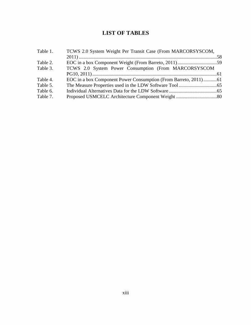
LIST OF TABLES
Table 1. TCWS 2.0 System Weight Per Transit Case (From MARCORSYSCOM,
2011) ................................................................................................................58 Table 2. EOC in a box Component Weight (From Barreto, 2011) ................................59 Table 3. TCWS 2.0 System Power Consumption (From MARCORSYSCOM
PG10, 2011) .....................................................................................................61
Table 4. EOC in a box Component Power Consumption (From Barreto, 2011) ...........61 Table 5. The Measure Properties used in the LDW Software Tool ...............................65 Table 6. Individual Alternatives Data for the LDW Software .......................................65 Table 7. Proposed USMCELC Architecture Component Weight .................................80

xiv
THIS PAGE INTENTIONALLY LEFT BLANK
xv
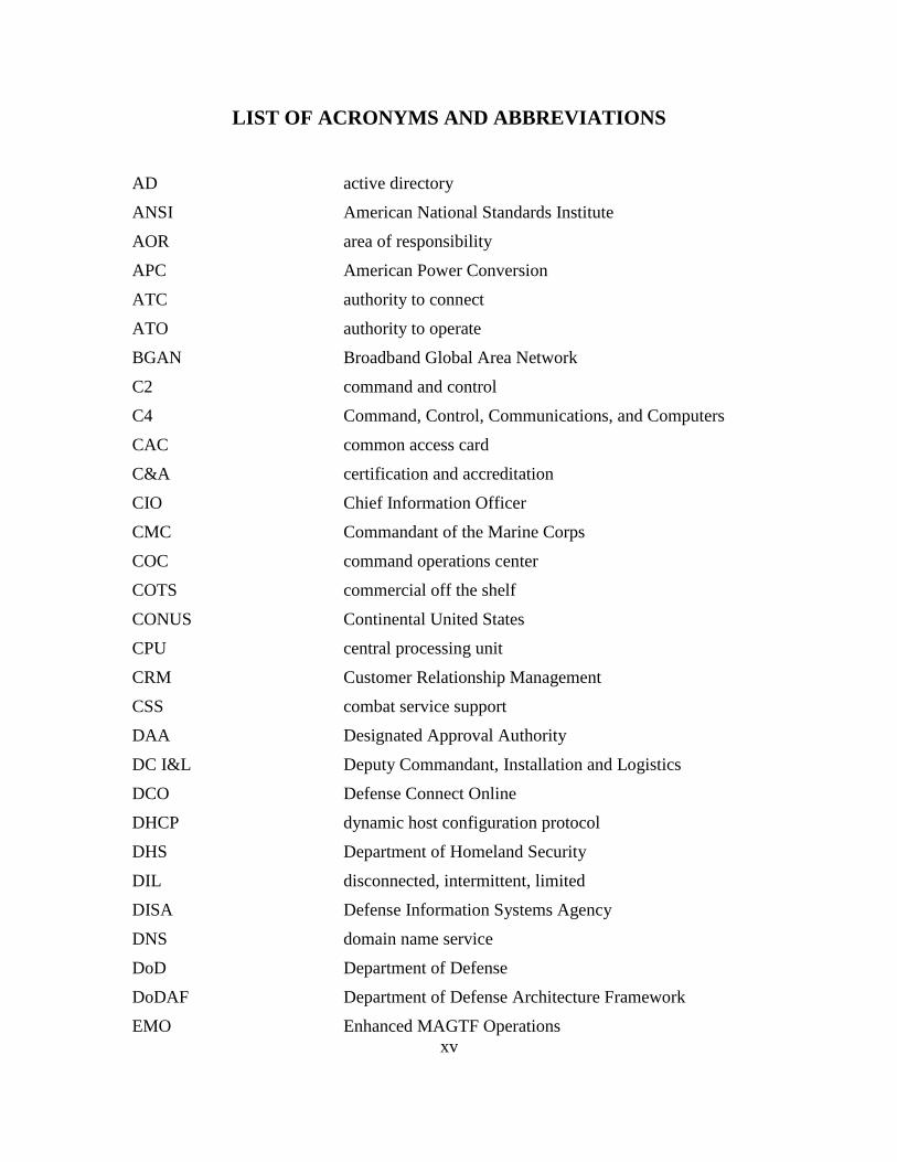
LIST OF ACRONYMS AND ABBREVIATIONS
AD active directory
ANSI American National Standards Institute
AOR area of responsibility
APC American Power Conversion
ATC authority to connect
ATO authority to operate
BGAN Broadband Global Area Network
C2 command and control
C4 Command, Control, Communications, and Computers
CAC common access card
C&A certification and accreditation
CIO Chief Information Officer
CMC Commandant of the Marine Corps
COC command operations center
COTS commercial off the shelf
CONUS Continental United States
CPU central processing unit
CRM Customer Relationship Management
CSS combat service support
DAA Designated Approval Authority
DC I&L Deputy Commandant, Installation and Logistics
DCO Defense Connect Online
DHCP dynamic host configuration protocol
DHS Department of Homeland Security
DIL disconnected, intermittent, limited
DISA Defense Information Systems Agency
DNS domain name service
DoD Department of Defense
DoDAF Department of Defense Architecture Framework
EMO Enhanced MAGTF Operations
xvi
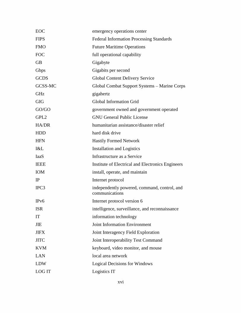
EOC emergency operations center
FIPS Federal Information Processing Standards
FMO Future Maritime Operations
FOC full operational capability
GB Gigabyte
Gbps Gigabits per second
GCDS Global Content Delivery Service
GCSS-MC Global Combat Support Systems – Marine Corps
GHz gigahertz
GIG Global Information Grid
GO/GO government owned and government operated
GPL2 GNU General Public License
HA/DR humanitarian assistance/disaster relief
HDD hard disk drive
HFN Hastily Formed Network
I&L Installation and Logistics
IaaS Infrastructure as a Service
IEEE Institute of Electrical and Electronics Engineers
IOM install, operate, and maintain
IP Internet protocol
IPC3 independently powered, command, control, and
communications
IPv6 Internet protocol version 6
ISR intelligence, surveillance, and reconnaissance
IT information technology
JIE Joint Information Environment
JIFX Joint Interagency Field Exploration
JITC Joint Interoperability Test Command
KVM keyboard, video monitor, and mouse
LAN local area network
LDW Logical Decisions for Windows
LOG IT Logistics IT
xvii
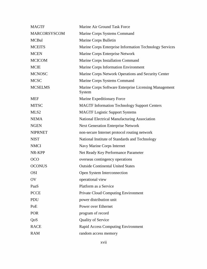
MAGTF Marine Air Ground Task Force
MARCORSYSCOM Marine Corps Systems Command
MCBul Marine Corps Bulletin
MCEITS Marine Corps Enterprise Information Technology Services
MCEN Marine Corps Enterprise Network
MCICOM Marine Corps Installation Command
MCIE Marine Corps Information Environment
MCNOSC Marine Corps Network Operations and Security Center
MCSC Marine Corps Systems Command
MCSELMS Marine Corps Software Enterprise Licensing Management
System
MEF Marine Expeditionary Force
MITSC MAGTF Information Technology Support Centers
MLS2 MAGTF Logistic Support Systems
NEMA National Electrical Manufacturing Association
NGEN Next Generation Enterprise Network
NIPRNET non-secure Internet protocol routing network
NIST National Institute of Standards and Technology
NMCI Navy Marine Corps Internet
NR-KPP Net Ready Key Performance Parameter
OCO overseas contingency operations
OCONUS Outside Continental United States
OSI Open System Interconnection
OV operational view
PaaS Platform as a Service
PCCE Private Cloud Computing Environment
PDU power distribution unit
PoE Power over Ethernet
POR program of record
QoS Quality of Service
RACE Rapid Access Computing Environment
RAM random access memory
xviii
RMOD Radio Module
RNOSC Regional Network Operations and Security Centers
RSTP rapid spanning tree protocol
ROMO range of military operations
RU rack unit
S&T science and technology
SaaS Software as a Service
SAN storage attached network
SAS serial attached SCSI
SATA serial ATA
SATCOM satellite communications
SCSI small computer system interface
SE supporting establishment
SIE service integration environment
SFP small form-factor pluggable
SOA service oriented architecture
SOS system of systems
SP Special Publication
SSD solid state drive
STOM Ship-to-Shore Objective Maneuver
SV systems view
SWLAN secure wireless local area network
SYSCON systems control
TB terabyte
TCWS Tactical Collaboration Work Suite
TDS Tactical Data System
TSOA Tactical Service Oriented Architecture
U unit
UPS uninterruptible power supply
USB universal serial bus
USMCELC United States Marine Corps Expeditionary Logistics Cloud
UUNS urgent universal needs statement
xix
VA volt-ampere
VDI virtual desktop infrastructure
VLAN virtual local area network
VM virtual machine
VoIP Voice over Internet protocol
VSAT very-small-aperture terminal
WiMAX Worldwide Interoperability for Microwave Access
Wireless STIG Wireless Security Technical Implementation Guide
xx
THIS PAGE INTENTIONALLY LEFT BLANK
xxi
ACKNOWLEDGMENTS
I must first thank God; He has given me the strength, perseverance, and
knowledge to complete this thesis. Without Him, none of this could have been possible.
Next, I must thank my family. To my magnificent wife, Antonieta, you are my
best friend, and I am blessed to have such a wonderful person to share life’s journeys
with; to my two exceptional children, Charles and Beatriz, you have added so much love
and joy to my life, more than you could ever imagine. The three of you have unselfishly
sacrificed so much, I am truly thankful for all your support, encouragement, and patience
these past two years.
I would also like to thank my father, Charles Ibatuan, who passed away last
December. He was always there for me and constantly gave me guidance and
reassurance that I could accomplish anything in life through hard work and dedication.
To my loving mother, Patricia, thank you for all your love and support; your wisdom has
inspired me to succeed in all aspects of my life. To my brothers, Juan and Joe, thank you
for your prayers and friendship; you both are great brothers.
In addition to my immediate family, I need to thank my in-laws, friends, and co-
workers who helped me through this process. They, like the rest of my family, have
understood the efforts involved and pressure of pursuing this degree.
I must also thank my advisors; Dr. Dan Boger and Mr. Albert Barreto, your
insight, experience, and time have helped me immensely in the formatting and structuring
of my thesis. You both were instrumental in keeping me focused and smiling. I would
also like to thank Jane Barreto for assisting with all the administrative documents
required for the success of this thesis.
Last, I would like to thank the United States Marine Corps for allowing me to
pursue a higher education and HQMC Installation and Logistics Department for funding
my research. I want to thank others who have aided my thesis in one form or another, in
particular: Cesar Valdesuso, Aaron Burciaga, Maro Enoka, Nicholas Linkowitz, Robert
Anderson, Miles Tiglao, Benjamin Hernandez, and Zaffrenarda King.
xxii
THIS PAGE INTENTIONALLY LEFT BLANK
1
I. INTRODUCTION
A. EXPEDITIONARY CLOUD COMPUTING
The Department of Defense (DoD) is planning an aggressive move toward cloud
computing technologies. The cloud-computing concept has been floating around the
private information technology (IT) sector for a number of years and has benefited
organizations with cost savings, increased efficiencies, and flexibility by sharing
computer resources through network connections (Donovan & Katzman, 2010). The push
for cloud computing has been driven by the 25 Point Implementation Plan to Reform
Federal Information Technology Management that highlighted the shift to a Cloud first
policy (Kundra, 2010). This plan to reform Federal IT has accelerated the DoD, and more
specifically, the Marine Corps, toward cloud computing technologies making this
relatively new paradigm inevitable.
In 2012, the Marine Corps’ Chief Information Officer provided the Private Cloud
Computing Environment (PCCE) Strategy with the intent to align enterprise processes
and improve the way IT supports the institution in scalable instances such as Enterprise,
Distributed, and Expeditionary environments (Anderson, 2012). With the known benefits
of cloud computing in mind, Brigadier General Nally stated in his foreword to
Anderson (2012), “The USMC Cloud Strategy can reduce cost and save energy by
consolidating and centralizing resources, including hardware, software, and licenses
(Foreword, para. 1). As “America’s Expeditionary Force in Readiness,” the Marine Corps
has identified the need for adapting IT services that are more effective, efficient, and
responsive to its current and future responsibilities (Anderson, 2012, p. 1). The Marine
Corps identified in its vision for cloud computing that it would support forward deployed
forces in the following ways:
(1) Facilitate secure communications and IT services that provide robust, near real
time access to mission critical data, information, and knowledge;
(2) Provide a net-centric information environment enabling battalion and below
forces with access to rear echelon data resources;
2
(3) Enable the ability to conduct dispersed operations in a non-linear battlespace
over greater distances by providing more information with fewer deployed resources;
(4) Implement virtualization technologies to reduce footprint, reduce energy usage
requirements, and increase speed of network implementation (Anderson, 2012, p 4).
The mission of the Marine Corps requires its forces to operate in austere, high
threat environments. When a Marine Corps unit deploys, Marines are required to install,
operate, and maintain (IOM) communication networks. These communication networks
are required to provide commanders with effective command and control (C2) and
Logistics Services capabilities to support the expeditionary operating forces (Dunford,
2012). These types of environments are similar to natural or man-made disaster
environments that present first responders with limitations due to the unpredictable and
non-deterministic nature of these events. A recent method that first responders have used
in order to provide ad-hoc rapid communication networks during these types of incidents
are through the use of Hastily Formed Networks (HFN).
Hastily Formed Networks are defined as rapidly established network of
organizations from different communities that work together to achieve a critical mission
in a shared conversion space (Newlon, Patel, Pfaff, Vreede, & MacDorman, 2009).
Denning (2005) coined this term at the Naval Postgraduate School after the United States
Department of Defense and Homeland Security learned that the quality of incident
responses relied heavily on the network that supported the disaster relief efforts. Zeng,
Wei, and Joshi (2008) described the most severe type of HFN to be the Infrastructure-less
Communication System. This condition occurs where the existing communications
infrastructure has been completely damaged and is inoperable requiring first responders
to IOM an expeditionary communications network in austere environments similar to the
Marines Corps.
Barreto (2011) explored the applicability of virtualization technologies within
HFN architectures. The research focused on the integration of virtual desktops,
applications, and data, within an emergency operations center (EOC) that was supported
by the communications and power infrastructure of a HFN (Barreto, 2011). In his six
3
separate experiments, his research discovered that the integration of virtual machine
(VM) technologies into the HFN is both possible and feasible. By combining these two
models, which merge to form a system of systems comprised of power, communications,
and a mobile EOC, this approach added significant capabilities to the original HFN
architecture and value for the users of the system (Barreto, 2011).
The urgency for the Marine Corps to implement cloud computing needs to be
tempered by a comprehensive evaluation that includes but is not limited to emerging:
cloud computing technologies, cloud computing architectures, VM technologies, and
local versus remote logistical data types and subsets. More specifically, the Marine Corps
has not fully determined whether current cloud computing architectures can be applied in
an expeditionary environment. This thesis will explore the feasibility of using a cloud
computing architecture that will support enhanced logistical decision support systems in
an expeditionary environment.
B. RESEARCH QUESTION
As the Marine Corps transitions to a cloud computing IT environment, it needs to
determine if current architectures will support enhanced logistics decision support
systems in an expeditionary environment. This thesis will explore the feasibility of a
using cloud computing architecture with virtualization technologies that supports
enhanced logistical decision support systems in an expeditionary environment. An
analysis of the current cloud computing architectures, virtual technologies, and Marine
Corps logistic systems will be used in order to present a cloud computing architecture
that “best” supports expeditionary logistics for the Marine Corps.
1. Do current cloud computing architectures support the applications and data
analysis needs for the Marine Corps’ logistical systems in an expeditionary Cloud
environment?
2. What is required in the Marine Corps analytics suite to support data
synchronization in the employment of an expeditionary cloud computing System?
4
3. What technologies are required to allow these data sets to be downloaded and
synchronized, and will these be available in an expeditionary environment?
C. BENEFITS
Potential benefits from this research include a proposed cloud computing
architecture based on current and emerging technologies that can be used as a conceptual
model for a scalable enterprise solution. This model can then be used to build a
prototype IT architecture that promotes the use of cloud computing and VM technologies
which managers and senior leaders can use for implementation. Limitations due to time
and available resources are expected although the hardware necessary to construct the
models and licensing for the SAS software are in place and readily available.
Recommendations may include but will not be limited to whether cloud computing
architectures will/will not support expeditionary logistics.
D. RESEARCH DESIGN AND METHODOLOGY
The design of this study used a constructive research approach that complements
the structured but unpredictable nature of research in the information systems technology
field. According to Crnkovic (2010) the constructive research method is the construction,
based on existing knowledge, of artifacts that are practical and/or theoretical which aim
to solve a domain specific problem and which create knowledge about how that problem
can be solved. The problem is that the Marine Corps needs to define capabilities, required
standards, and the conditions under which to employ a cloud computing architecture that
will support enhanced logistic systems in a deployed environment. This thesis explored
theoretical and practical solutions to address a cloud computing architecture that will
support Marine Corps’ Expeditionary Logistics requirements.
This study involved secondary research that leveraged public and private sector
cloud computing, cloud computing architectures, virtualization technologies, and
logistical support systems. The research methodology focuses on past, current, and
emerging technologies and evaluated business best practices and IT architectures that
currently support logistic systems. A software program called Logical Decision for
Windows (LDW) was used to compare the utility rankings of current cloud computing
5
technologies and the results were used to develop an enhanced cloud computing
architecture that “best” supports expeditionary logistics for the Marine Corps.
Information for this thesis was gathered from Headquarters Marine Corps, Installations
and Logistics (I&L) Department; Headquarters Marine Corps, Command, Control,
Communications, and Computers (C4) Department; Marine Corps Systems Command
(MARCORSYSCOM), various DoD and Marine Corps websites, Naval Postgraduate
School research library, and other on-line, non-academic resources.
E. THESIS ORGANIZATION
1. Chapter II: Technology and Definitions
Chapter II will define cloud computing and provide an overview of its potential
benefits and risks. It will briefly describe Cloud Computing Service and Deployment
Models that are currently used in private and public sector organizations. It will include a
brief overview of the DoD Joint Information Environment, the DoD Architecture
Framework, and the DoD Enterprise Cloud Environment. It will also include an overview
of Microsoft, VMware, and XEN virtual technologies. The last portion of the chapter will
provide a brief overview of the Hastily Formed Network four-layer model that is
currently being deployed for humanitarian assistance/disaster relief (HA/DR) efforts.
2. Chapter III: Evaluation of Current Development Models
Chapter III will describe some of the current and emerging technologies for the
Marine Corps and the Naval Postgraduate School. Specifically, this chapter will cover the
Marine Corps Enterprise Information Technology Services (MCEITS), Marine Corps
Enterprise Network (MCEN), the Marine Corps PCCE, and Tactical Collaboration Work
Suite 2.0. Additionally, this chapter will cover the Marine Corps Marine Air Ground Task
Force (MAGTF) Logistic Support Systems (MLS2), Global Combat Support Systems –
Marine Corps (GCSS-MC), and the Tactical Service Oriented Architecture (TSOA). This
chapter will conclude with a description of the HFN Emergency Operations Center in a
box.
6
3. Chapter IV: Analysis and Application
Chapter IV will include the analysis and application of all data gathered
throughout the research process. It will combine the concepts in the previous chapters,
analyze them, and present recommended practices for cloud computing architectures that
use virtualization technologies to support expeditionary logistics. This chapter will
include the data that was entered into the LDW software program as well as the results
from running the program. Chapter IV will conclude with the proposed cloud computing
architecture model that “best” supports expeditionary logistics for the Marine Corps.
4. Chapter V: Conclusion
Chapter V will conclude this thesis. It will include a conclusion and
recommendations.
7
II. TECHNOLOGY AND DEFINITIONS
A. CLOUD COMPUTING
1. Definition
Cloud computing has steadily grown in popularity and is a technological concept
that continues to evolve. Although the term cloud computing is relatively new, this
concept can be considered the latest stop in the evolution of distributed computing.
Distributed computing is coordinated computing that involves multiple remote computers
connected through local or wide area networks. A popular form of distributed computing
is distributed computing through client-server where clients are able to access servers,
locally or over the Internet, in order to make use of the server resources. Over the years
this term has gained widespread use to what we now call cloud. Cloud computing is by
definition distributed computing but in a more specialized form.
The term cloud computing has many connotations and for some, it suggests grid
computing with mechanisms for people or businesses to acquire additional compute,
storage, or specialized hardware computing resources (Lehman & Vajpayee, 2011). For
others, it signifies software as a service that runs its own applications or provides access
to third party software and offers a complete computing infrastructure where the Cloud
provider manages and monitors the entire customer’s computing activity (Lehman &
Vajpayee, 2011). Donovan and Katzman (2010) describe it in a way that compares cloud
computing to an electrical computing grid. In an electrical computing grid the power
company maintains and owns the electrical infrastructure, an electrical distribution
company disseminates the electricity to the users, and the consumer uses the resources
without ownership or operational responsibilities of the electrical infrastructure or the
distribution company (Donovan & Katzman, 2010). Similarly, a user’s Cloud computing
access enables shared resources, software, and information on-demand on a fee-for-
service basis (Donovan & Katzman, 2010).
The National Institute of Standards and Technology (NIST) Definition of Cloud
Computing Special Publication (SP) 800–145 described cloud computing as an
8
availability model “enabling ubiquitous, convenient, on-demand network access to a
shared pool of configurable computing resources that can be rapidly provisioned and
released with minimal management” (Mell & Grance, 2011, p. 2). In order to
successfully promote availability, the NIST SP 800–145 designated that Cloud
computing must comprise five essential characteristics. According to the NIST, the five
essential service models for effective cloud computing are: “on-demand self-service,”
where users can automatically request and obtain provisions of server time and network
storage; “broad network access,” where access to network is available through multiple
platforms; “resource pooling,” where the provider collocates resources to service many
users regardless of location; “rapid elasticity,” where resources are provided quickly and
in a scalable manner; and “measured Service,” where the provider transparently meters,
monitors, controls, and documents service usage for billing (Mell & Grance, 2011, p. 2).
2. Benefits of Cloud Computing
Cloud computing has become a requirement for all DoD agencies due to the
recent adoption of the 25 Point Implementation plan to reform Federal IT and its shift to a
Cloud first policy that promotes increased use of the Cloud and shared services (Kundra,
2010). This is mainly due to the fact that services within Cloud computing contain
resources with many benefits such as reduced cost, mobility, and flexibility (Geelan,
2008). Cloud computing has been used in the private IT sector for many years and has
benefited organizations with cost savings and increased flexibility by sharing IT
resources such as applications, storage devices, and servers (Donovan & Katzman, 2010).
Similar to the private sector, the public sector, including the DoD, recognized that Cloud
computing have several potential benefits over current IT systems in the DoD.
A cloud is…an ideal place from which to make capabilities available to
the whole enterprise. While, in the DoD, we have encountered challenges
moving towards a service-oriented architecture (SOA), in the private
sector, companies like Google and Salesforce are basing their business
models on an insatiable public hunger for software and applications as a
service. Emulating their delivery mechanisms within our own private
cloud may be key to how we realize the true potential of net-centricity.
(Statement before the U.S. house of representatives armed services
9
committee subcommittee on terrorism, unconventional threats and
capabilities, 2009, p. 19)
One of the main reasons why the Federal Government and the DoD has adopted
Cloud computing is cost reduction. Cloud computing relies on Internet-based services
and resources to provide computing services to its customers, freeing the customer from
the burden and costs of maintaining the IT network since it is managed by an external
provider (United States Government Accountable Office, 2010). The use of Cloud
computing reduces the requirement to hire special IT staff, and businesses do not have to
worry about maintaining and upgrading hardware, software, or fixing bugs, as all the
maintenance is done by the provider (Arno, 2011). In fact, the President’s budget has
identified the adoption of Cloud computing in the federal government as a way to more
efficiently use the billions of dollars spent annually on federal IT (USGAO, 2010).
Along with cost savings, the increased IT mobility and flexibility that Cloud
computing offers can significantly benefit the Federal Government, especially the DoD.
Possessing IT mobility and flexibility are important characteristics to have in the DoD. In
regards to mobility, one of the DoD Chief Information Officer’s responsibilities is to
address international issues associated with information and communications
technologies, including technologies for the non-automatic movement, transmission, or
reception of information (Department of Defense, 2005). With Cloud computing,
consumers will be able to access applications and data from a “Cloud”
anywhere in the world on demand. The consumers are assured that the
Cloud infrastructure is very robust and will always be available at any
time. Computing Services need to be highly reliable, scalable, and
autonomic to support ubiquitous access, dynamic discovery and
composability. (Buyya, Yeo, Venugopal, Broberg, & Brandic, 2008, p. 4)
The DoD Chief Information Officer stated, “Long term planning is essential, but
at the same time we have to be focused on the individuals on the ground and giving them
what they need” (Corrin, 2011, para. 6). One specific mobility benefit that Cloud
computing can offer to the DoD is Battle Space Situational Awareness with the Common
Operating Picture (Kubic, 2008). Accessing the Cloud and being able to view statuses of
troops, missions, weapons, and supplies as well as tactical Intelligence, surveillance, and
reconnaissance (ISR) feeds from anywhere in the world can definitely give the strategic
10
and tactical warfighter the resources necessary to be successful on the battlefield (Kubic,
2008).
Increased IT flexibility is a benefit that the DoD IT sector can also potentially
exploit from Cloud computing. Cloud computing capabilities can be rapidly and
elastically provisioned to quickly scale out, and rapidly released to scale in; to the
consumer, capabilities available for provisioning appear to be unlimited and can be
purchased in any quantity at any time (Mell & Grance, 2011). Additionally, Cloud
computing does not aim at certain special applications but produces various applications
supported by cloud, and one cloud can support different applications running at the same
time (Zhang, Chen, Zhang, & Huo, 2010). The DoD mission and unpredictable
requirements change, resources for each mission can vary between large scaled strategic
operations to small-scaled conflicts in third world countries. The flexibility and
scalability that Cloud computing offers has the potential to improve operational and
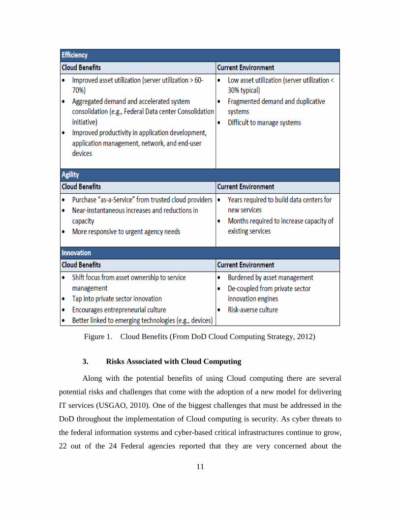
tactical effectiveness for forward deployed forces. Figure 1 summarizes the areas in
which the DoD and its subordinate agencies can benefit from the use of cloud computing
technologies.
11
Figure 1. Cloud Benefits (From DoD Cloud Computing Strategy, 2012)
3. Risks Associated with Cloud Computing
Along with the potential benefits of using Cloud computing there are several
potential risks and challenges that come with the adoption of a new model for delivering
IT services (USGAO, 2010). One of the biggest challenges that must be addressed in the
DoD throughout the implementation of Cloud computing is security. As cyber threats to
the federal information systems and cyber-based critical infrastructures continue to grow,
22 out of the 24 Federal agencies reported that they are very concerned about the
12
potential information security risks associated with Cloud computing (USGAO, 2010).
Since Cloud computing uses shared distributed resources through networks in the open
environment, it makes addressing security problems extremely difficult in the
development and implementation of Cloud computing applications (Shen & Tong, 2011).
One of the major security concerns that the DoD must be apprehensive with is the
possibility of ineffective or noncompliant service provider security controls which could
lead to vulnerabilities affecting the confidentiality, integrity, and availability of agency
information (USGAO, 2010). The Federal Information Processing Standards (FIPS) 200,
Minimum Security Requirements for Federal Information and Information Systems,
provides agencies the baselines for minimum information security controls in the
protection of confidentiality, integrity, and availability of federal information systems and
the data processed, stored, and transmitted by those systems (USGAO, 2010). The FIPS
200 states that Federal agencies, including the DoD, are required to conduct certification,
accreditation, and security assessments periodically (USGAO, 2010). These types of
assessments evaluate security controls, develop and implement plans of action designed
to correct deficiencies, reduce or eliminate vulnerabilities, authorize operating systems
and any associated system connections, and monitor system security controls (USGAO,
2011). The certificate and accreditation process, as well as periodic security inspections
could be extremely difficult for the DoD since it would be required to conduct security
inspections on dynamically provisioned infrastructures (Kubic, 2008).
In addition to security inspections on dynamically provisioned infrastructures,
Cloud computing has also raised questions about the privacy and security of data at all
classification levels (Hayes, 2008). The DoD handles a substantial amount of sensitive
data that contain multiple classification levels that can complicate the migration, storage,
and control of data stored on a server that resides off-site and under multiple authorities
(Corrin, 2011). The DoD raised concerns with the potentially inadequate background
security investigations for service provider employees that could potentially lead to
increased risk of wrongful activities by malicious insiders and the insecure or ineffective
deletion of agency data by cloud providers once services have been completed (USGAO,
2010). Since data in the DoD have multiple classification levels, it must be assigned
13
privilege-based access ensuring that all data is properly labeled and access according to
its classification (Kubic, 2008). If service providers for Cloud computing do not have the
same security investigation or data storage/deletion standards as the DoD, there is the risk
of classified or sensitive data being exposed that could ultimately pose significant threats
to National Security.
B. CLOUD COMPUTING SERVICE MODELS
The NIST Cloud Computing Synopsis and Recommendations, SP 800–146,
described three models that define the different types of services that a cloud computing
environment can provide its consumers. According to Badger, Grance, Patt-Corner, and
Voas (2012), these three different cloud computing service models have different
strengths that are suitable for a wide variety of customers and business objectives.
1. Software as a Service
The first service model is Cloud Software as a Service (SaaS). The Cloud SaaS
model is a capability provided to a consumer to use the Cloud provider’s applications or
software that run on the cloud infrastructure (Mell & Grance, 2011). In this type of cloud
computing service model the Cloud can provide its customers access to software
applications like email or other office software tools, or can present an environment to
build and operate their own software (Badger et al., 2012). In this model the Cloud
service provider will be responsible to take care of all the software development,
maintenance of equipment, and software upgrades. The user simply accesses the
application or software through an Internet connection.
2. Platform as a Service
The second service model is Cloud Platform as a Service (PaaS). According to
Mell and Grance (2011), this model is a capability provided where the customer deploys,
onto the cloud computing infrastructure, consumer created or acquired applications that
were created using programing languages, libraries, services and tools provided by the
supplier. In this type of cloud computing service model, customers are supplied with an
environment that gives them the capability to develop, operate, and manage applications.
14
The customer does not control or manage the Cloud infrastructure but has control over
the deployed software applications and possibly the application hosting environment
configurations (Badger et al., 2012).
3. Infrastructure as a Service
The last service model that NIST SP 800–145 defined for cloud computing is the
Cloud Infrastructure as a Service (IaaS) model. This model is a capability provided to the
consumer to provision processing, storage, networks, and other fundamental computing
resources allowing the customer to deploy and run arbitrary software including operating
systems and applications (Mell & Grance, 2011). This cloud computing service model is
known to provide its customers better interoperability and portability because the
building blocks such as network protocols, legacy device interfaces, and CPU instruction
sets within the IaaS model are relatively well defined (Badger et al., 2012).
C. CLOUD COMPUTING DEPLOYMENT MODELS
In addition to the Cloud computing service models, the NIST SP 800–145 defined
four deployment models that can be used to deploy cloud computing services to its
customers. According to Badger et al. (2012), depending on the type of Cloud
deployment model that is implemented, the Cloud may have limited private computing
resources or it could have access to large quantities of remotely accessed resources. Also,
just like the cloud computing service models, the deployment models have different
strengths and various tradeoffs in how the customer controls their resources, costs, and
the availability of resources (Badger et al., 2012).
1. Private Cloud Model
The Private Cloud model was the first deployment model described in the NIST
SP 800–145. The Private Cloud is a Cloud infrastructure that is operated solely for a
specific organization. It may be owned, managed, and operated by the organization, a
third party or a combination of two; and, the Cloud infrastructure may exist on or off
premises (Mell & Grance, 2011). Additionally, the United States Federal Chief
Acquisition Officers Council (2012) acknowledges that the Private Cloud model allows
15
for the most control in selecting who is provided access to the Cloud environment, which
if managed correctly, could be considered the most secure of the four models.
2. Community Cloud Model
The second model described was the Community Cloud model. In the Community
Cloud model the infrastructure is shared by several organizations and supports a specific
community that have shared interests such as mission, security requirements, policy, or
compliance considerations (Mell & Grance, 2011). This type of model allows for a mixed
degree of control for its customers and may be managed by the organization or by a third
party
3. Public Cloud Model
The third model described by the NIST SP 800–145 was the Public Cloud Model.
In this model the Public Cloud infrastructure is made available to the general public or a
large industry group and is owned by an organization that is selling Cloud services (Mell
& Grance, 2011). In this type of Cloud deployment model, the customer or organization
purchasing access to the Cloud infrastructure do not know or control who the other
customers are that share the same Cloud environment (CAOC, 2012).
4. Hybrid Cloud Model
The last Cloud deployment model was the Hybrid Cloud. According to Mell &
Grance (2011), the Hybrid Cloud model is a composition of two or more Cloud
infrastructures, such as Private Cloud, Community Cloud, or Public Cloud that remain
unique entities; however, they are bound together by standardized or proprietary
technology. This type of Cloud model also allows for a mixed degree of control for its
customers and may be managed by the organization or by a third party.
D. DOD JOINT INFORMATION ENVIRONMENT
The DoD continues to work on its Joint Warfare Operations between its services,
industry partners, and other government agencies. The DoD Doctrine for Joint Operations
describes Joint Warfare as the integration of all U.S. military capabilities; air, land, sea,
16
space and special operation forces, synchronized and integrated to achieve strategic and
operational objectives through integrated campaigns and major operations (Joint Chiefs
of Staff, 2010). In order for Joint Operations to be successful, commanders must be able
to maintain control over the battlefield with Command and Control capabilities that give
leaders the shared awareness of the battlefield space in order to measure, report, and
correct battlefield performance (JCS, 2010). In the article written by Roulo (2012), the
Deputy Chief Information Officer (CIO) for the DoD said that everything that the DoD
does is about information sharing and that the central solution for information sharing is
the DoD Joint Information Environment (JIE).
The DoD has assigned the responsibilities for evolving the JIE to the Defense
Information Systems Agency (DISA). In DISA’s Strategic Plan 2013–2018, its number
one strategic goal is the JIE. The DISA Strategic Goal for JIE is to,
Evolve a consolidated collaborative, and secure joint information
environment, enabling end-to-end information sharing and interdependent
enterprise services across the Department that are seamless, interoperable,
efficient, and responsive to joint and coalition Warfare requirements.
(Hawkins, 2013, p. 9)
When it is complete, the JIE will enable every user to access information from
anywhere, on approved devices, in a secure and reliable method (Roulo, 2012). With the
newly evolving JIE capabilities, the DoD has begun its efforts towards implementing
updates to its current version of the Department of Defense Architecture Framework.
E. DEPARTMENT OF DEFENSE ARCHITECTURE FRAMEWORK
The Department of Defense Architecture Framework (DoDAF) is defined by the
DoDAF Version 2.02 as the
overarching, comprehensive framework and conceptual model enabling
the development of architectures to facilitate the ability of Department of
Defense (DoD) managers at all levels to make decisions more effectively
through organized information sharing across the Department, Joint
Capability Areas (JCAs), Mission, Component, and Program boundaries.
(Department of Defense Architecture Framework, 2011, p. 3)
17
This framework focuses extensively on guiding the development of architectures
supporting the adoption and the execution of an information superiority-enabled concept
of operations within the DoD. All DoD components are expected to conform to the
DoDAF to ensure the reuse of information and that artifacts, models, and viewpoints
within DoD agencies are shared with common understanding (DoDAF, 2011).
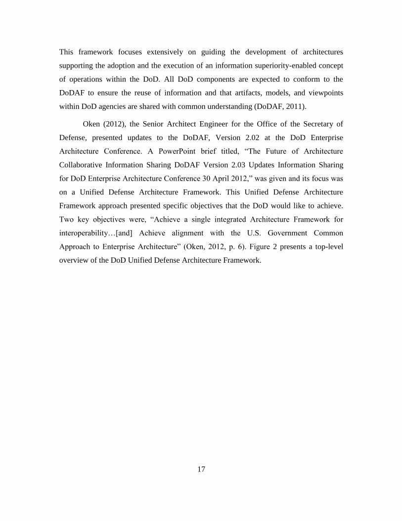
Oken (2012), the Senior Architect Engineer for the Office of the Secretary of
Defense, presented updates to the DoDAF, Version 2.02 at the DoD Enterprise
Architecture Conference. A PowerPoint brief titled, “The Future of Architecture
Collaborative Information Sharing DoDAF Version 2.03 Updates Information Sharing
for DoD Enterprise Architecture Conference 30 April 2012,” was given and its focus was
on a Unified Defense Architecture Framework. This Unified Defense Architecture
Framework approach presented specific objectives that the DoD would like to achieve.
Two key objectives were, “Achieve a single integrated Architecture Framework for
interoperability…[and] Achieve alignment with the U.S. Government Common
Approach to Enterprise Architecture” (Oken, 2012, p. 6). Figure 2 presents a top-level
overview of the DoD Unified Defense Architecture Framework.
18
Figure 2. Unified Defense Architecture Framework
(From Oken, 2012)
With a better understanding of the definitions and purposes of both the JIE and
DoDAF, it is important to recognize that these will rely heavily upon the development
and implementation of the DoD Enterprise Cloud Environment that will be discussed in
the next section.
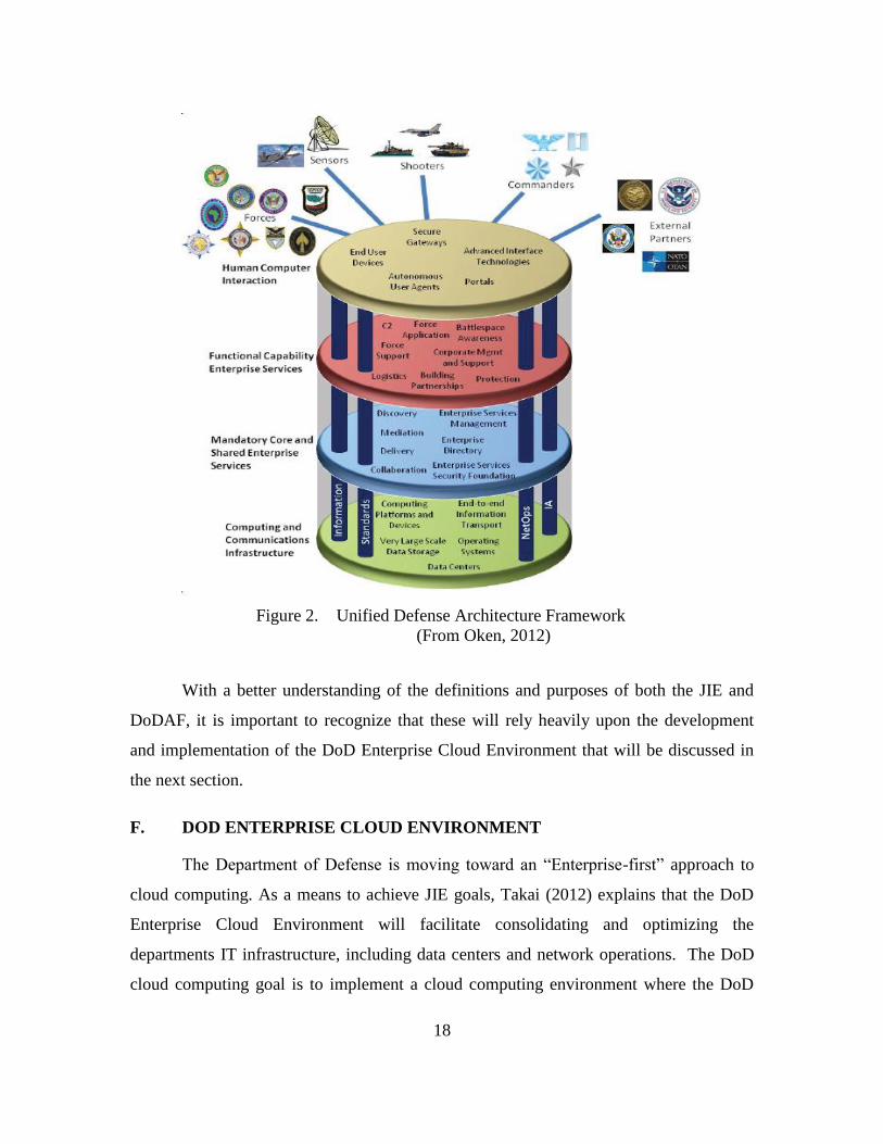
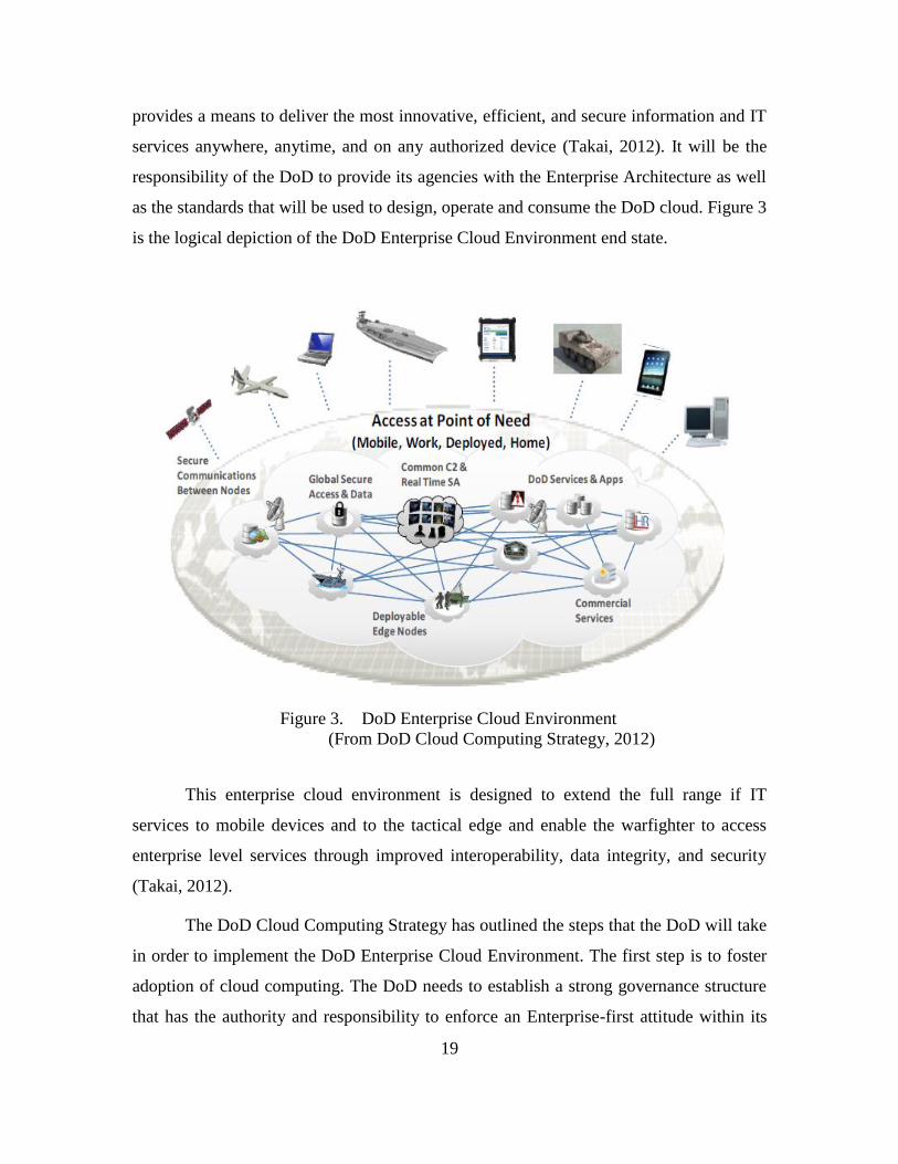
F. DOD ENTERPRISE CLOUD ENVIRONMENT
The Department of Defense is moving toward an “Enterprise-first” approach to
cloud computing. As a means to achieve JIE goals, Takai (2012) explains that the DoD
Enterprise Cloud Environment will facilitate consolidating and optimizing the
departments IT infrastructure, including data centers and network operations. The DoD
cloud computing goal is to implement a cloud computing environment where the DoD
19
provides a means to deliver the most innovative, efficient, and secure information and IT
services anywhere, anytime, and on any authorized device (Takai, 2012). It will be the
responsibility of the DoD to provide its agencies with the Enterprise Architecture as well
as the standards that will be used to design, operate and consume the DoD cloud. Figure 3
is the logical depiction of the DoD Enterprise Cloud Environment end state.
Figure 3. DoD Enterprise Cloud Environment
(From DoD Cloud Computing Strategy, 2012)
This enterprise cloud environment is designed to extend the full range if IT
services to mobile devices and to the tactical edge and enable the warfighter to access
enterprise level services through improved interoperability, data integrity, and security
(Takai, 2012).
The DoD Cloud Computing Strategy has outlined the steps that the DoD will take
in order to implement the DoD Enterprise Cloud Environment. The first step is to foster
adoption of cloud computing. The DoD needs to establish a strong governance structure
that has the authority and responsibility to enforce an Enterprise-first attitude within its
20
Departments and to improve and reform IT financial, acquisition, and contracting
practices (Takai, 2012). The second step is to optimize data center consolidation. Kundra
(2010), pointed out in The 25 Point Implementation Plan that the Federal Government
needed to apply “Shared Solutions” pushing the requirement to close a minimum of 800
data centers, reducing the total amount of data centers that are government operated to
roughly 1300. This federal plan directed the DoD to consolidate its IT infrastructure as
well as to find additional methods, such as virtualization, to reduce the computing
footprint even more.
The third step is to establish the DoD Enterprise Cloud Infrastructure. This Cloud
infrastructure will incorporate the DoD core data centers and will be the engine that runs
the DoD Enterprise Network (Takai, 2012). The final step to implement the DoD
Enterprise Cloud Environment is to continue to deliver Cloud services that provide
improved capabilities at a reduced cost. The DoD is currently providing its consumers
with Cloud services. The following services are owned and operated by DISA and hosted
in the DoD enterprise data centers: Defense Connect Online (DCO); Global Content
Delivery Service (GCDS); Forge.mil development platform tools; RightNow Customer
Relationship Management (CRM) tools; and Rapid Access Computing Environment
(RACE) for processing resources (Takai, 2012). As the DoD pushes forward to refine and
mature its cloud computing strategy, Takai (2012) stresses the importance of active
participation and commitment by all of its departments to ensure consistency and
optimized benefits.
G. VIRTUALIZATION TECHNOLOGY
Virtual technology has grown tremendously over the years and it seems that
private IT vendors have tied their products into virtualization. Virtualization technology
can be traced back to the 1960s IBM System 370 Mainframe and has matured to the point
where every Fortune 100 Company and all branches of the military are using it (Barreto,
2011). Troy and Helmke (2009) describe this break-through technology as being
advantageous to companies because it saves money, energy, and space by maximizing the
use of underutilized equipment that would normally sit around and idle. Lowe’s (2009)
21
definition of virtualization is the abstraction of one computing resource from another
computing resource enabling multiple operating systems to run simultaneously on the
same physical hardware.
Virtualization varies from a single device to very large data centers and can be
applied to servers, networks, applications, or storage systems. The main idea of
virtualization is to create logical instantiations of computers known as VMs that are
managed as pools of computing resources (Barreto, 2011). VM software, known as a
hypervisor, enables the sharing of physical hardware. Hypervisors are the software
virtualization layer that is installed on the computing resources allowing everything
above it to communication with the hardware that it is installed on (Troy & Helmke,
2009). The sharing of physical hardware is accomplished by creating a virtualization
layer that transforms the physical hardware into virtual devices seen by VMs.
Hypervisors are the virtualization layer that functions as the foundation for the rest of the
virtual product line (Lowe, 2009). There are two main types of hypervisors, type-1 and
type-2.
Hypervisor Type-1 is a client hypervisor that runs directly on the system hardware
that is being virtualized and is completely independent from the operating system, and
thus is often referred to as a bare-metal hypervisor (Lowe, 2009). This type of hypervisor
is the most popular type for companies in the virtualization industry because it is focused
on high performance, Return on Investment (ROI), and scalability (Virtual Computer,
2013). A Type-2 hypervisor is a type of client hypervisor that requires a host operating
system, and the host operating system provides the I/O device support and memory
management (Lowe, 2009). This type of hypervisor is the less popular of the two
because it makes the end user’s environment more complex and the IT department
requirements tougher to secure, support, and manage (Virtual Computer, 2013). This
thesis will specifically look at Type-1 Hypervisors for inclusion in the prototype model.
Users can use different types of devices as clients. These devices can range from
laptop computers, zero and thin clients, and even smart phones to connect to a virtual
computer that has been configured with an operating system and software (Barreto,
2011). These devices are known as virtual desktops and can access the virtual
22
environment while connected to a wired local area 802.3 Ethernet network, or on an
802.11 or 802.16 wireless networks (Barreto, 2011). Barreto (2011) explains that remote
access can be achieved through Virtual Private Network (VPN), which can leverage the
public Internet or wireless mesh network. The next few paragraphs will briefly describe a
few industry leaders in virtualization technologies specifically in the x86 server
virtualization infrastructure market deployed on standard x86-based physical servers.
1. Microsoft
Microsoft is one of many successful companies that continue to share the
virtualization market. Their commercial-based company has been in the industry for
almost five years. Within the five year span they have delivered four major hypervisors;
Hyper-V and System Center 2008, Live Migration and Cluster Shared Volumes in
Windows Server 2008 R2, System Center 2008 R2, and Hyper-V in Windows Server
2012 (Bittman, Weiss, Margevicius, & Dawson, 2012). The most recent Hyper-V in
Windows Server is said to be a complete virtualization platform that provides increased
scalability and performance when compared to the older Microsoft products. Microsoft
(2013) is quoted as saying,
Whether you are looking to help increase VM mobility, help increase VM
availability, handle multi-tenant environments, gain bigger scale, or gain
more flexibility, Windows Server 2012 with Hyper-V gives you the
platform and tools you need to increase business flexibility with
confidence. (Microsoft, 2013, Server Virtualization, para. 4)
Bittman et al. (2012) conducted an evaluation of commercial vendor-based
virtualization competitors covering hypervisors to create VMs, shared OS virtualization
technologies, server virtualization administrative management, and server virtualization
embedded management. When comparing Microsoft to other virtual industry leaders,
Bittman et al. (2012) provide general strengths and areas of caution for Microsoft virtual
technologies:
Strengths
Administrative environment that is familiar to Windows administrators
23
Installed base of Windows, especially a large number of Windows-only
enterprises
Strength of solution for midsize enterprises and low price
Company financial strength
Cautions
Difficulty converting or surrounding a strong VMware installed base,
especially in large enterprises
Competing with VMware for channel and service provider influence
Relatively slow cadence of delivery of enhancements (Microsoft, para. 5).
2. VMware
VMware is also one of many successful companies in the virtualization market.
Over the years it has introduced VMware Infrastructure 3, VMware vSphere 4.0,
VMware ESX 3.x, VMware ESX 4.x, and VMware vSphere 5.0 (Bittman et al., 2012).
The new VMware vSphere 5.0 is said to be a complete virtualization platform that is
designed to create a more dynamic and flexible IT infrastructure for businesses. VMware
(2013) is quoted as saying,
VMware virtualization solutions offer you many advantages…they are the
world’s most proven, robust, and reliable virtualization platform—the
choice of more than 500,000 customers, including 100% of the Fortune
100. Our solutions cover the spectrum from desktop to datacenter,
preserve your existing IT investment, and integrate with the management
tools you already have. (VMware, 2013, Why Choose VMware, para. 1)
VMware virtualization is known for its ability to work with a variety of hardware
and software as an open standards-based approach to licensing and interoperability. In the
evaluation conducted by Bittman et al. (2012) on the commercial vendor-based
virtualization competitors, VMware was also presented with general strengths and areas
of concern for their virtualization technology:
Strengths
Virtualization strategy and road map that lead to private and hybrid cloud
computing
Technology leadership and innovation
High customer satisfaction
24
Large installed base (especially among large enterprises), and a large and
growing number of service providers using vSphere (enabling choice of
service providers)
Cautions
Business model depends on vSphere revenue to expand and invest in
adjacent markets
Maintaining high revenue growth in a more product- and price-
competitive market that is already 50% penetrated
Focused homogeneous virtualization vision in a market where customers
are concerned about lock-in, and service providers want differentiation
(VMware, para. 7).
3. XEN
Unlike Microsoft and VMware, which are commercial vendors, Xen is an open-
source standard for hardware that is licensed under the GNU General Public License
(GPL2). Xen has been around for 10 years and has developed virtualization technologies
that have powered the world’s largest Clouds in production and is the foundation for
many commercial products such as Huawei UVP, Oracle VM, and XenServer (Xen
Project, 2013). The Xen technology is known to industry as mature, stable, and versatile.
A few of Xen’s latest releases are the Xen Hypervisor 4.2.1, Xen Cloud Platform 1.6, and
Xen ARM. The following detailed descriptions were given for the latest technology
releases:
Xen is an open-source type-1 or baremetal hypervisor, which makes it
possible to run many instances of an operation system…Xen Cloud
Platform (or XCP) is a turnkey open source virtualization solution that
provides out-of-the-box virtualization and Cloud…Xen ARM Project is a
Xen based Hypervisor that targets embedded and mobile devices on
the ARM architecture. (Xen Project, 2013, What is the Xen Hypervisor,
para. 1)
H. HASTILY FORMED NETWORK
Hastily Formed Networks (HFNs) are not just portable networks that are set up in
the immediate aftermath of a disaster when existing communications infrastructures have
been destroyed; HFNs are defined as a rapidly established network of organizations from
different communities that work together to achieve critical missions in a shared
25
conversion space (Newlon, 2009). Denning (2005) coined this term at the Naval
Postgraduate School after the United States Department of Defense and Homeland
Security learned that the quality of incident responses relied heavily on the network that
supported the disaster relief efforts. This concept has been formally described by the
HFN Research Group as five elements: (1) A network of people established rapidly; (2)
From different communities; (3) Working together in a shared conversation space; (4) In
which they plan, commit to, and execute actions to; (5) Fulfill a large, urgent mission
(Tatham & Kovacs, 2010). A Four Layer Model was created in order to provide
organizations guidance on how to effectively establish HFNs and to assist organizations
in addressing the evolution of technologies, data-intensive applications and social issues
for disaster response (Nelson, Stamberger, & Steckler, 2011). This Four Layer Model
consists of a Physical Layer, Network Layer, Application Layer, and a Human Cognitive
Layer that will be discussed in the following sections.
1. Physical Layer
The physical layer deals with the basic level of what is required to build a HFN
(Nelson et al., 2011). Within the Physical layer there are four main categories; Power,
Human Needs, Physical Security, and Network Operations Center. The first category consists
of electrical power. HFN technology requires power sources to function. In many cases
immediately following a disaster in a region, the power grid infrastructure has been damaged
or destroyed causing organizations to supply their own electrical power to operate their
technical equipment. The second category is the Human Support Needs. Most first
responders will deploy with some basic logistical items; however they will eventually need to
procure additional items if the disaster relief efforts are prolonged. Nelson et al. (2011) state
that it is important to consider how disaster relief personnel will get food, water, shelter, fuel,
hygiene, and medical care while they are providing relief efforts.
The third category is the physical security. This is considered to be one of the
most important categories that need to be addressed because it includes the security of
personnel, equipment, and facilities. If these items are not obtained then the relief efforts
could suffer from the lack of resources or certain organizations might be required to leave
26
the disaster area due high risk security concerns that threaten their organization (Nelson
et al., 2011). The last category in the Physical Layer consists of the Network Operation
Center. The Network Operation Center is the central part of any HFN. It could be a
building, mobile command unit, or simply just a tent depending on what resources are
available. The Network Operation Center is used to address communications network
considerations such as managing bandwidth, securing the network, and wireless or other
radio frequency interference problems (Nelson et al., 2011).
2. Network Layer
The Network Layer provides the backbone of the communications system within
HFNs. There are a number of technologies that can be used to create the network;
however, according to Nelson et al. (2011), there are three main technologies that are
used to create HFNs: Worldwide Interoperability for Microwave Access (WiMAX),
Meshed WiFi, and a satellite communications (SATCOM) System. WiMAX, also known
as IEEE 802.16, is a terrestrial broadband point-to-point or point-to-multipoint wireless
bridge technology (Nelson et al., 2011). It has proven to work well in HFNs because it is
relatively inexpensive, easy to deploy, reliable, and has a range up to 50 miles with high
throughput of 54 bits per second (Epperly, 2007). The most common frequencies for
WiMAX are 5.8 and 2.4 gigahertz (GHz) and are usually deployed side-by-side along
with a SATCOM terminal and Meshed WiFi in a hub/spoke configuration (Nelson et al.,
2011). This technology is used to provide a link from the disaster area to the nearest
working telecommunications infrastructure.
Satellite Internet access communications provides the HFN the ability to connect
to the Internet when existing communications infrastructure are degraded or destroyed.
The most common types of portable satellite systems used in HFNs are the Very Small
Aperture Terminal (VSAT) and Broadband Global Area Network (BGAN) (Nelson et al.,
2011). These types of SATCOM terminals can be rapidly deployed anywhere there is a
clear line of site to the service provider’s satellites. Meshed WiFi, also known as IEEE
802.11, access points can be deployed to create Wireless local area networks that can
provide Internet access for mobile devices such as laptops, wireless phones, or remote
27
sensors (Zeng, Wei, & Joshi, 2008). The typical speeds for Meshed WiFi are 10 to 100
megabytes per second, and this type of Wireless LAN can be extended by positioning
multiple wireless access points around the disaster area to increase the footprint of the
wireless network up to several square miles (Nelson, et al., 2011).
3. Application Layer
The Third Layer in HFNs is the Application Layer. Here the HFN becomes the
backbone for various applications such as email, basic web access, file transfer, and chat
programs (Nelson et al., 2011). Certain Internet protocol (IP) based applications such as
Voice over Internet protocol (VoIP) has become increasingly important since applications
like these do not have to rely on pre-existing infrastructures and can operate solely across
a HFN. As the growth of smartphones, tablets, video, and collaboration and Incident
Management portal tools increases, the required bandwidth for the use of these
technologies has grown as well (Nelson et al., 2011). Supporting these new demands
brings along new challenges for HFNs. The traditional push-to-talk radio systems that use
Ultra High Frequencies, Very High Frequencies, and High Frequencies are still a critical
part of Hastily Formed Networks; however, one of the biggest challenges that will be
discussed later is the interoperability challenge that these devices bring to HFNs.
4. Human Cognitive Layer
HFNs also take into account the human cognitive realm (Nelson et al., 2011). The
effectiveness of a HFN depends on human components, and some believe that this
element is the most challenging part of deploying disaster relief efforts. The Human
Cognitive layer consists of four key components, Organizational, Economic, Political,
and Social/Cultural (Nelson et al., 2011). Problems in these areas can limit the
effectiveness of a HFN. The first component is Organizational. Organizational Unity of
effort but the lack of unity of command can often cause agencies to interfere with each
other’s normal business operations and can directly affect unity of effort between
organizations (Nelson et al., 2011). Also, the lack of interoperability between radio
systems can cause confusion and waste resources when organizations are not able to
communicate and collaborate with one another. The collaboration problem within HFNs
28
will also be discussed in further detail as it can negatively affect key elements of disaster
response.
The second component of the Human Cognitive Layer is Economic. The cost and
availability of communications equipment can be expensive for organizations that have
limited budgets. Certain organizations do not have the equipment, technical personnel
and services to support themselves during disaster relief efforts (Nelson et al., 2011). This
can cause critical services and equipment to be unavailable for organizations when they
are most required. Also, communications equipment brought in by early responders can
sometimes be viewed as competition for the local area service providers (Nelson et al.,
2011). Being seen as competition can often interfere with an organizations ability to
provide support for a disaster effectively.
The third component of the Human Cognitive Layer is Political. The local
government rules and regulations can be challenging especially when dealing with
communications technology. This can include radio frequency licensing and the
discouraging of the use of Voice over Internet Protocol phones because it could be
perceived as a threat to the established telephone carriers (Nelson et al., 2011). These
types of challenges that the local government can force on HFN technologies can reduce
the amount of support responders are able to provide.
The final category of the Human Cognitive Layer is Social/Cultural. The
immediate aftershock of a disaster usually attracts several international organizations that
want to participate in the relief efforts. More often than not these diverse organizations
have difficulty working with one another due to biases, differences in cultures, languages,
or sponsors of their groups (Nelson et al., 2011). Some organizations may not want to
work with other organizations because of a perceived conflict of interest (Nelson et al.,
2011). Also, organizations with different operating structures such as a very rigid top-
down command structure can have friction with organizations that have a more
consensus-driven operating model (Nelson et al., 2011).
29
III. CURRENT DEVELOPMENT MODELS AND TECHNOLOGY
This chapter introduces both current and emerging models and technologies. It
presents the Marine Corps’ current enterprise communication systems, cloud computing
environment, and current and emerging logistical technologies. Additionally, two cloud
computing and virtualization communication systems are introduced, one from the
Marine Corps and one from the Naval Postgraduate School. A proposed cloud
computing architecture that supports expeditionary logistics for the Marine Corps will
require that the system be compatible with the Marine Corps’ enterprise systems and
have the capability to support and/or host certain logistical applications. The models and
technology described in this chapter allows for the development of salient characteristics
that the proposed architecture must possess. These will be described in more details in
Chapter IV.
A. MARINE CORPS ENTERPRISE INFORMATION TECHNOLOGY
SERVICES
Marine Corps Systems Command (MCSC) is the Marine Corps’ agent for the
acquisition and sustainment of systems and equipment used to accomplish its war
fighting missions (Marine Corps System Command, 2013). The Secretary of the Navy
has given the MCSC Commander the management authority and accountability for
information systems, communications systems, and network infrastructure systems and
equipment assigned to Marine Corps Expeditionary Forces (SECNAVINST 5400.15C
CH-1, 2011). This unit has a unique contribution to the Marine Corps in that it acquires
and sustains weapons systems, equipment and IT for the Marine Corps forces (Brogan,
2010). A component of MCSC is Product Group 10 (PG10) that has oversight and
responsibility for the MCEITS program of record (POR).
MCEITS is an enterprise service that is a “core enabler of computing and
communications capabilities of the Marine Air-Ground Task Force Command and
Control (MAGTF C2) Framework and the Marine Corps’ C2 Systems of Systems (SOS)”
(Olson, n.d., p. 2). It provides the capacity, facilities, hardware, and software
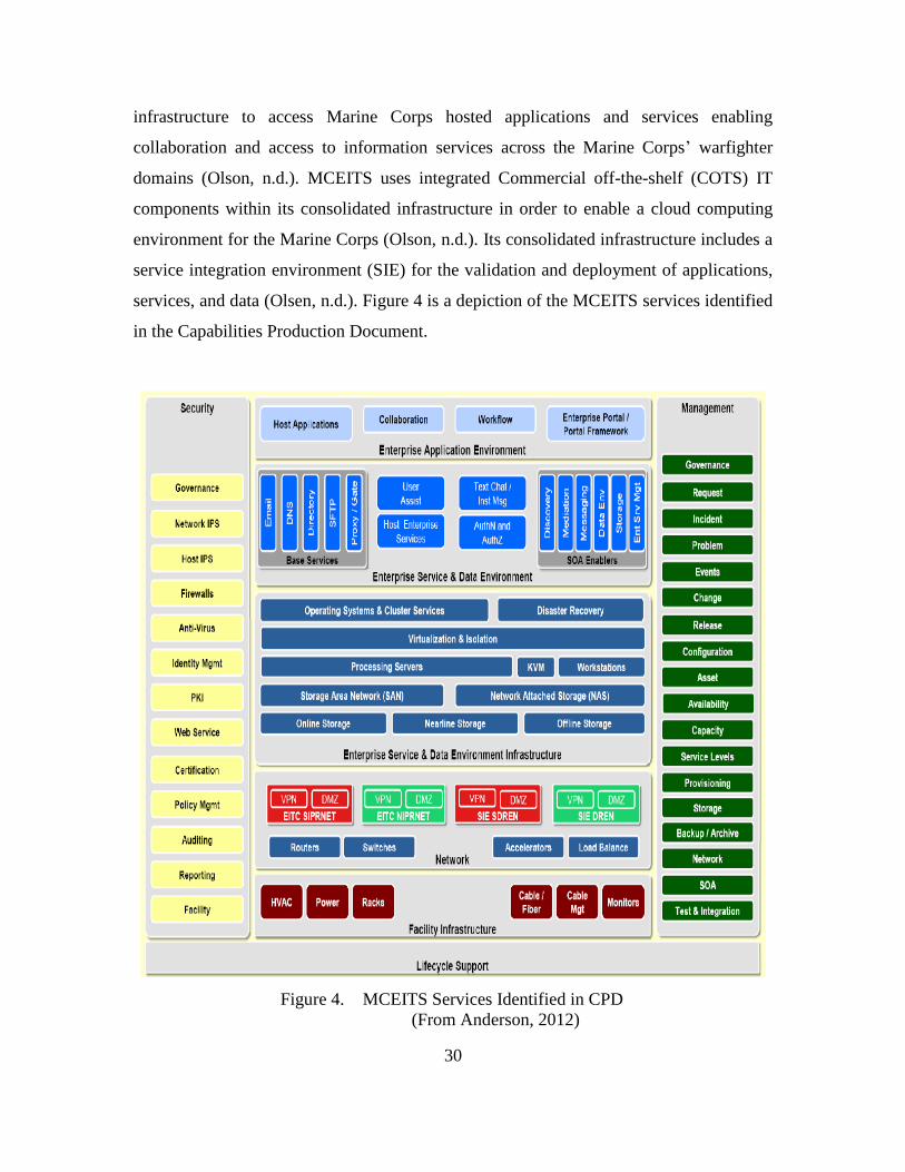
30
infrastructure to access Marine Corps hosted applications and services enabling
collaboration and access to information services across the Marine Corps’ warfighter
domains (Olson, n.d.). MCEITS uses integrated Commercial off-the-shelf (COTS) IT
components within its consolidated infrastructure in order to enable a cloud computing
environment for the Marine Corps (Olson, n.d.). Its consolidated infrastructure includes a
service integration environment (SIE) for the validation and deployment of applications,
services, and data (Olsen, n.d.). Figure 4 is a depiction of the MCEITS services identified
in the Capabilities Production Document.
Figure 4. MCEITS Services Identified in CPD
(From Anderson, 2012)
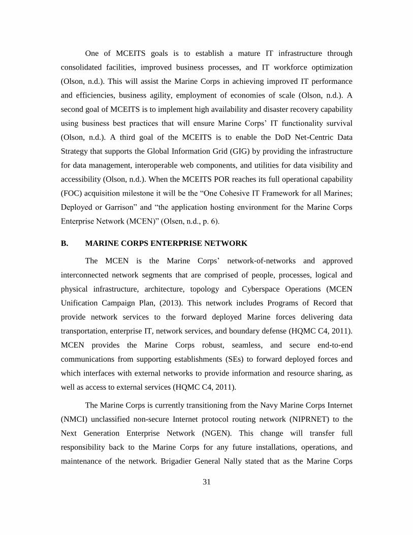
31
One of MCEITS goals is to establish a mature IT infrastructure through
consolidated facilities, improved business processes, and IT workforce optimization
(Olson, n.d.). This will assist the Marine Corps in achieving improved IT performance
and efficiencies, business agility, employment of economies of scale (Olson, n.d.). A
second goal of MCEITS is to implement high availability and disaster recovery capability
using business best practices that will ensure Marine Corps’ IT functionality survival
(Olson, n.d.). A third goal of the MCEITS is to enable the DoD Net-Centric Data
Strategy that supports the Global Information Grid (GIG) by providing the infrastructure
for data management, interoperable web components, and utilities for data visibility and
accessibility (Olson, n.d.). When the MCEITS POR reaches its full operational capability
(FOC) acquisition milestone it will be the “One Cohesive IT Framework for all Marines;
Deployed or Garrison” and “the application hosting environment for the Marine Corps
Enterprise Network (MCEN)” (Olsen, n.d., p. 6).
B. MARINE CORPS ENTERPRISE NETWORK
The MCEN is the Marine Corps’ network‐of‐networks and approved
interconnected network segments that are comprised of people, processes, logical and
physical infrastructure, architecture, topology and Cyberspace Operations (MCEN
Unification Campaign Plan, (2013). This network includes Programs of Record that
provide network services to the forward deployed Marine forces delivering data
transportation, enterprise IT, network services, and boundary defense (HQMC C4, 2011).
MCEN provides the Marine Corps robust, seamless, and secure end‐to‐end
communications from supporting establishments (SEs) to forward deployed forces and
which interfaces with external networks to provide information and resource sharing, as
well as access to external services (HQMC C4, 2011).
The Marine Corps is currently transitioning from the Navy Marine Corps Internet
(NMCI) unclassified non-secure Internet protocol routing network (NIPRNET) to the
Next Generation Enterprise Network (NGEN). This change will transfer full
responsibility back to the Marine Corps for any future installations, operations, and
maintenance of the network. Brigadier General Nally stated that as the Marine Corps
32
moves back to a government owned and government operated (GO/GO) network, it is
essential for disparate MCEN elements to be unified (MUCP, 2013). The “unification and
synchronization of disparate MCEN elements will ensure the MCEN’s ability to securely
and rapidly deliver a robust and seamless information environment in accordance with
the Marine Corps Information Environment Strategy” (MUCP, 2013, p. 2).
One of the objectives for the Marine Corps’ unified MCEN is to have it centrally
managed by the Marine Corps Network Operations and Security Center (MCNOSC) and
supported by the Regional Network Operations and Security Centers (RNOSC), MAGTF
Information Technology Support Centers (MITSCs), Marine Corps Installation
Command (MCICOM) Regional G-6’s, and Operating Force Commands (MUCP, 2013).
Figure 5 displays a map of the Marine Corps’ current and future locations for its
Enterprise IT Centers (EITC), MITSCs, and MCNOSC.
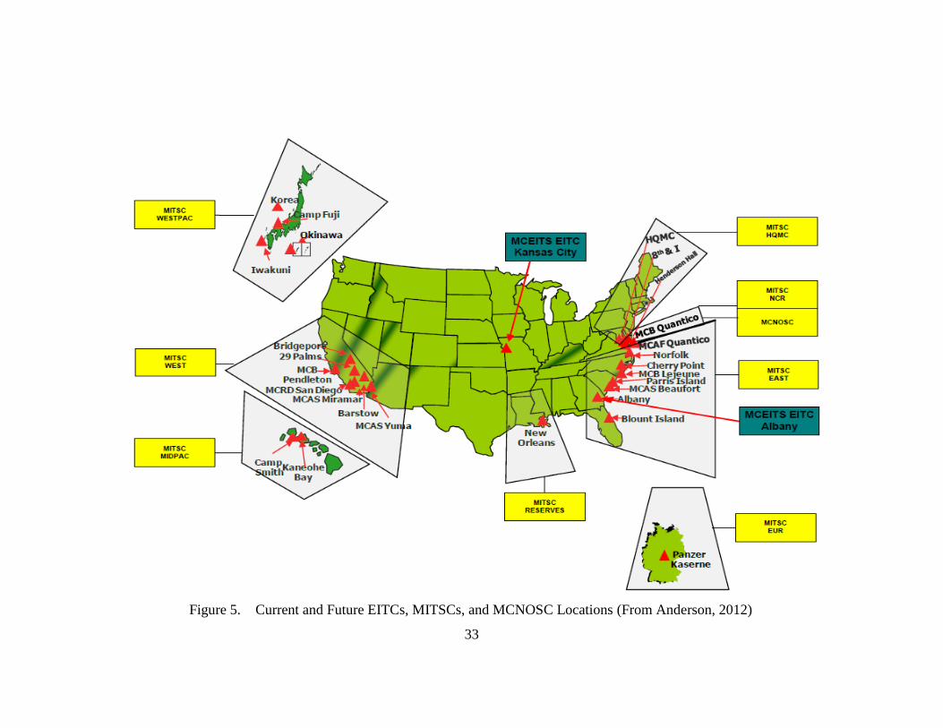
33
Figure 5. Current and Future EITCs, MITSCs, and MCNOSC Locations (From Anderson, 2012)
MITSC WESTPA C
MITSC WEST
MITSC MI>PAC
34
Another objective for the Marine Corps’ unified MCEN is that it must possess
unified capabilities, which is defined as the integration of voice, video, and data services
delivered across an interoperable, secure, and highly available network infrastructure
(MUCP, 2013). The last objective for the future MCEN is that it must “provide an
increased ability for the warfighter to collaborate and share information for heightened
situational awareness and provide access to knowledge bases in which actionable
information can be researched expeditiously” (MUCP, 2013, p. 2). The Marine Corps
will continue to improve upon the MCEN in order to ensure its networks meet the
warfighter’s emerging requirements. “We must enhance our MCEN to better serve our
Operational Forward Deployed Forces by improving our seamlessness, reachback,
interoperability, and security to the Base/Post/Station enclaves and leveraging our
Enterprise IT services” (HQMC C4, 2011, “Why is it Important,” para. 1). This will
position the Marine Corps to better influence the development of the DoD JIE and allow
it to take a leadership role in the DoD as it seeks to increase security and improve
efficiency in the Defense Information System Network (MUCP, 2013).
C. THE MARINE CORPS PRIVATE CLOUD COMPUTING
ENVIRONMENT
Headquarters Marine Corps C4 distributed its PCCE Strategy in May 2012. This
strategy was published to “ensure the Marine Corps complies with and aligns to the
federal requirements and guidelines by ensuring that IT services are distributed across the
enterprise in fiscally and operationally efficient and effective means” (Anderson, 2012,
Foreward, para. 2). The Marine Corps’ PCCE Strategy coincides with the NIST
definition of cloud computing and Federal Cloud Computing Strategy. The Marine Corps
PCCE will provide access from anywhere across the Marine Corps information
environment at any time via the MCEN. The MCEN, MCEITS, and Marine Corps PCCE
will synchronize efforts to ensure a unified approach to achieve the Marine Corps
enterprise private cloud computing vision (Anderson, 2012). Anderson (2012) states that
the Marine Corps PCCE will promote availability and must align to the following
characteristics:
35
Secure on-demand self-service. End users connected to the MCEN, via
secure means, can access available services from the cloud provider when
and where needed.
Flexible broad network access. Capabilities are available over the
MCEN and accessed through standard internetworking mechanisms. This
is a tenet of the “Plug and Play” resource that supports Strategic Objective
2 of the MCIENT: Improve Reach-back Support and Interoperability.
Resource Pooling. The Marine Corps’ computing resources are pooled to
serve multiple end users. Eleven primary data centers with multiple
expeditionary extensions are available through different physical and
virtual resources. These are dynamically assigned and reassigned
according to end user demand. To meet peak demands resource pooling
allows for more efficient and cost effective use of resources that otherwise
normally require over allocation. Examples of pooled resources include
storage, processing, memory, facilities, and virtual machines.
Elastic. Cloud capabilities can be rapidly provisioned (quickly increased,
decreased or dynamically provisioned). To the end user, the capabilities
(e.g., storage and processing) available for provisioning often appear to be
unlimited.
Measured Service. Cloud systems with a use of metering capability
appropriate to the type of service (e.g., storage, processing, bandwidth,
and active user accounts) can automatically control and optimize resource
use. Resource usage can be monitored, controlled, and reported, providing
transparency for both the provider and consumer of the utilized service.
These metrics provide data required for return on investment analysis and
assist in identifying shortfalls and surpluses (p. 3).
In addition, the Marine Corps PCCE must align with the following three service
models (Anderson, 2012).
Cloud Software as a Service (SaaS). The capability to use the provider’s
applications on demand and manage application data through means such
as backup and end user data sharing. This capability is provided to the
consumer via the provider’s applications running on a cloud infrastructure.
The applications are accessible from various client devices through a thin
client interface such as a web browser (e.g., web-based email). The
consumer does not manage or control the underlying cloud infrastructure
including network, servers, operating systems, storage, or even individual
application capabilities, with the possible exception of limited user
specific application configuration settings.
Cloud Platform as a Service (PaaS). The capability to use the provider’s
tools and execution resources to develop, test, deploy and administer
applications. This capability is provided to the consumer to deploy into the
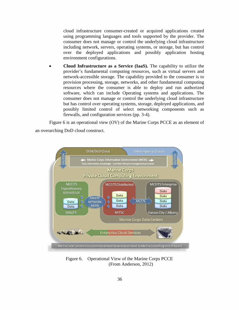
36
cloud infrastructure consumer-created or acquired applications created
using programming languages and tools supported by the provider. The
consumer does not manage or control the underlying cloud infrastructure
including network, servers, operating systems, or storage, but has control
over the deployed applications and possibly application hosting
environment configurations.
Cloud Infrastructure as a Service (IaaS). The capability to utilize the
provider’s fundamental computing resources, such as virtual servers and
network-accessible storage. The capability provided to the consumer is to
provision processing, storage, networks, and other fundamental computing
resources where the consumer is able to deploy and run authorized
software, which can include Operating systems and applications. The
consumer does not manage or control the underlying cloud infrastructure
but has control over operating systems, storage, deployed applications, and
possibly limited control of select networking components such as
firewalls, and configuration services (pp. 3-4).
Figure 6 is an operational view (OV) of the Marine Corps PCCE as an element of
an overarching DoD cloud construct.
Figure 6. Operational View of the Marine Corps PCCE
(From Anderson, 2012)
37
D. TACTICAL COLLABORATIVE WORK SUITE 2.0
The Marine Corps currently uses the Tactical Collaborative Work Suite (TCWS)
2.0 to provide the MAGTF with a standardized platform that will support web-enabled,
virtualized, deployable information management suite for collaborative and C2
requirements (iGov TCWS, 2011). The TCWS 2.0 was the third and final response to the
2005 I Marine Expeditionary Force (MEF) and 2006 III MEF urgent universal needs
statement (UUNS) and is considered to be the gap filler for the MCEITS Expeditionary
and the Combat Operations Command (Walters, 2012). The TCWS 2.0 Project Officer
stated that the “TCWS 2.0 is a small, lightweight ruggedized, modular and scalable
standardized capability set allowing Marines to deploy, manage, and maintain tactical
and collaborative services in support of Expeditionary Maneuver Warfare” (Walters,
2012, “Tactical Collaboration,” para. 1).
The project Office has developed this suite to deploy in multiple environments
such as a standalone environment, as part of the Marine Corps enterprise, and/or in
joint/coalition networks (Walters, 2012). This man-portable tactical collaborative system
uses a complete commercial off the shelf (COTS) solution and industry and government
open standards, which allow the system to grow and shrink according to mission
requirements (MARCORSYSCOM Information System and Infrastructure Product
Group 10, 2011). The TCWS 2.0 can deploy in three different modularity options, the
Full Development Package, Lite Development Package, and Rapid Deployment Package
(MARCORSYSCOM PG10, 2011).
All three system packages are composed of a virtualized hosting platform,
segmented physical hardware and virtualized software platforms that provide portal,
synchronous, and asynchronous collaboration capabilities (iGov, 2011). According to
Smartronix (2007), who developed the first version of TCWS, a baseline TCWS system
incorporates a Microsoft Windows Server, active directory (AD), SharePoint Portal
Server, SQL Server, Exchange, Outlook Web Access, Internet Information Server, File
and Print Services, CITRIX Presentation Server, Symantec Antivirus and Backup Exec,
and Altiris Server Management all hosted within a VMware virtualized infrastructure.
38
In March 2012 the TCWS 2.0 received the authority to operate (ATO) and
authority to connect (ATC) certification and accreditation (C&A) from the Marine Corps’
Designated Approval Authority (DAA). The Marine Corps has accepted 71 TCWS
systems, which have a five-year hardware warranty and software assurance through the
Marine Corps Software Enterprise Licensing Management System (MCSELMS)
(Walters, 2012). The TCWS Project Office is currently documenting lessons learned
from the TCWS 2.0 to ensure a smooth transition to the MCEITS Expeditionary Platform
in the future (Walters, 2012).
E. MARINE AIR GROUND TASK FORCE LOGISTICS SUPPORT
SYSTEMS
As the Marines transitions from over a decade of overseas contingency operations
(OCO) the logistical footprint of the Marine Corps has increased in the number of end
items, equipment weight, and energy requirements (Marine Corps Installation and
Logistics Roadmap, 2013). This increased logistical footprint is not consistent with the
expeditionary ethos of the Marine Corps, and future threats will dictate a leaner logistics
support solutions to support operational concepts like Ship-to-Shore Objective Maneuver
(STOM), Enhanced MAGTF Operations (EMO), Future Maritime Operations (FMO),
and Expeditionary Maneuver Warfare (MCILR, 2013). These types of operational
concepts have proven to rely heavily on the logistics community and will require the
Deputy Commandant, Installation and Logistics (DC I&L), along with advocates from
the Marine Corps’ operating forces, to “lighten the MAGTF” in order to save money,
make the Marine Corps more expeditionary, and to reduce the overall logistics
sustainment requirements (MCILR, 2013). The Marine Corps Installation and Logistics
Roadmap (2013) characterize expeditionary logistics as:
Being lighter, modular, more energy efficient
Being responsive, reliable, scalable, and timely
Supporting MAGTF fires, maneuvers, and force protection
Leveraging bases, stations, and depots to deploy, sustain, and redeploy
forces
Leveraging technology to improve logistical capabilities, capacity, and
interoperability
39
Providing MAGTF Command and Control (C2) capability for deployment
and distribution operations
Creating an information network that transmits information and services
via assured end-to-end connectivity
Providing visibility of Marine Corps assets (equipment and supplies)
through item unique identification (IUID), radio frequency identification
(RFID), automated information technologies (AIT), and the automated
information systems (AIS) required to track and share logistics
information (p. 9).
Dunford (2012) states “expeditionary logistics provides lean, responsive, and
efficient support across all logistics function to include the distribution of supplies over
the last tactical mile in austere environments” (p. A1). Figure 7 provides an OV-1 of the
MAGTF expeditionary logistics capability and main operational nodes where key Marine
Corps operational activities take place across the range of military operations (ROMO)
and provides a description of the interactions between the expeditionary logistics
architecture and its environment, and between the architecture and external systems
(Dunford, 2012).
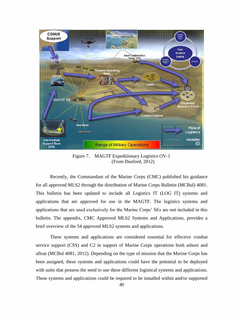
40
Figure 7. MAGTF Expeditionary Logistics OV-1
(From Dunford, 2012)
Recently, the Commandant of the Marine Corps (CMC) published his guidance
for all approved MLS2 through the distribution of Marine Corps Bulletin (MCBul) 4081.
This bulletin has been updated to include all Logistics IT (LOG IT) systems and
applications that are approved for use in the MAGTF. The logistics systems and
applications that are used exclusively for the Marine Corps’ SEs are not included in this
bulletin. The appendix, CMC Approved MLS2 Systems and Applications, provides a
brief overview of the 54 approved MLS2 systems and applications.
These systems and applications are considered essential for effective combat
service support (CSS) and C2 in support of Marine Corps operations both ashore and
afloat (MCBul 4081, 2012). Depending on the type of mission that the Marine Corps has
been assigned, these systems and applications could have the potential to be deployed
with units that possess the need to use these different logistical systems and applications.
These systems and applications could be required to be installed within and/or supported
41
by an expeditionary cloud computing architecture. As seen in the CMC approved MLS2
systems and applications, the GCSS-MC is one of the biggest logistical systems and is
taking over the majority of the Marine Corps logistics chain management for supply and
maintenance transactions. The GCSS-MC could be one of the principal logistic system
that the proposed cloud computing architecture would be required to support during
expeditionary logistic operations.
F. GLOBAL COMBAT SUPPORT SYSTEM – MARINE CORPS
GCSS-MC is known to be the “Marine Corps’ state-of-the- art, web-enabled
logistics IT system…the backbone of future Logistics Chain Management” (MCILR,
2013, p. 19). GCSS-MC is an enabler of streamlined logistics processes that can provide
accurate, real-time data both in garrison and in deployed environments resulting in an
enterprise-wide visibility of data (Marine Corps Warfighting Lab, 2013). The Marine
Corps Warfighting Lab (2013) states that GCSS-MC:
Speeds up the delivery of goods and services through automation of the
processes for requesting and tracking whatever materiel Marines need
Enables a single log-on, one point entry
Provides more accurate information about readiness
Makes it possible to shut down legacy systems that are difficult to upgrade
and expensive to maintain (p. 3).
GCSS-MC is going to be the centerpiece of future Marine Corps logistics IT. It
will implement and sustain a cutting edge business information technology system that
will provide global combat support capabilities to enhance the MAGTF and supporting
task organizations (Global Combat Support Systems-Marine Corps, 2013). It will deliver
integrated functionality and a logistics Shared Data Environment (SDE) implemented
through the use software, enterprise application integration/middleware software and web
portal software (GCSS-MC, 2013). The fielding of GCSS-MC Release 1.1 has been
completed and the program is on track in providing commanders decision-support
capabilities that provide enterprise-wide near real time visibility of data (MCILR, 2013).
42
G. TACTICAL SERVICE ORIENTED ARCHITECTURE
One of the challenges for the Marine Corps logistics community is the lack of
interoperability among IT systems (MCILR, 2013). Their current and legacy C2
architectures use different methods of storing, communicating, and displaying
information and since the systems do not communicate with one another their data is
uncorrelated (MCILR, 2013). The Marine Corps plan is to move to a service oriented
architecture (SOA) that provides point-to-point integration of information allowing a
variety of applications to communicate with each other over a network creating a shared
data environment (MCILR, 2013). The Marine Corps intent is to use the Tactical Service
Oriented Architecture (TSOA) to integrate existing disparate MLS2 and incorporate
business intelligence and other analytic tools to effectively monitor, filter, and mine
information in order to support user requirements (MCILR, 2013). In the Marine Corps
Tactical Service Oriented Architecture Technology Insertion Approach, Griggs and
McVicker (2011) define the TSOA goals as:
Provide an improved, standards-based approach to achieve information
sharing
Increase agility through cost and resource-effective reuse of service and
capabilities
Eventually replace the information “stovepipes” of the current deployed
tactical data systems (TDSs) with open architecture-based integration (p.
1).
The end state of the TSOA is a “common, scalable, service-oriented capability,
seamlessly employable on land and at sea, that enhances the lethality and effectiveness of
the MAGTF across the range of military operations through better decision-making,
collaboration, and shared understanding” (Griggs & McVicker, 2011, p. 1). Figure 8
illustrates the TSOA Framework:
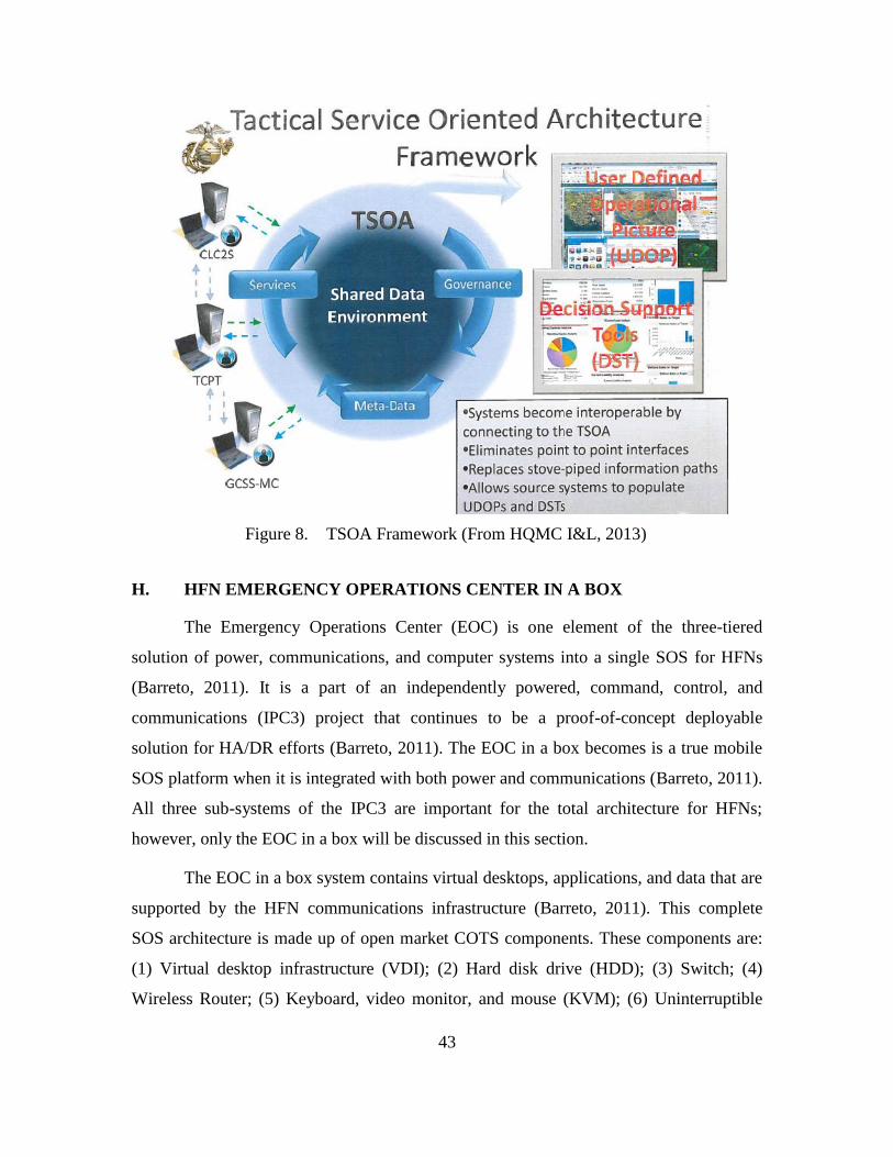
43
Figure 8. TSOA Framework (From HQMC I&L, 2013)
H. HFN EMERGENCY OPERATIONS CENTER IN A BOX
The Emergency Operations Center (EOC) is one element of the three-tiered
solution of power, communications, and computer systems into a single SOS for HFNs
(Barreto, 2011). It is a part of an independently powered, command, control, and
communications (IPC3) project that continues to be a proof-of-concept deployable
solution for HA/DR efforts (Barreto, 2011). The EOC in a box becomes is a true mobile
SOS platform when it is integrated with both power and communications (Barreto, 2011).
All three sub-systems of the IPC3 are important for the total architecture for HFNs;
however, only the EOC in a box will be discussed in this section.
The EOC in a box system contains virtual desktops, applications, and data that are
supported by the HFN communications infrastructure (Barreto, 2011). This complete
SOS architecture is made up of open market COTS components. These components are:
(1) Virtual desktop infrastructure (VDI); (2) Hard disk drive (HDD); (3) Switch; (4)
Wireless Router; (5) Keyboard, video monitor, and mouse (KVM); (6) Uninterruptible
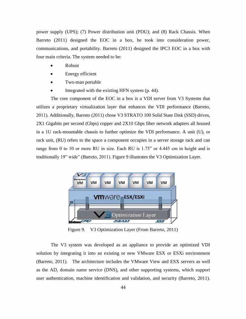
44
power supply (UPS); (7) Power distribution unit (PDU); and (8) Rack Chassis. When
Barreto (2011) designed the EOC in a box, he took into consideration power,
communications, and portability. Barreto (2011) designed the IPC3 EOC in a box with
four main criteria. The system needed to be:
Robust
Energy efficient
Two-man portable
Integrated with the existing HFN system (p. 44).
The core component of the EOC in a box is a VDI server from V3 Systems that
utilizes a proprietary virtualization layer that enhances the VDI performance (Barreto,
2011). Additionally, Barreto (2011) chose V3 STRATO 100 Solid State Disk (SSD) drives,
2X1 Gigabits per second (Gbps) copper and 2X10 Gbps fiber network adapters all housed
in a 1U rack-mountable chassis to further optimize the VDI performance. A unit (U), or
rack unit, (RU) refers to the space a component occupies in a server storage rack and can
range from 0 to 10 or more RU in size. Each RU is 1.75” or 4.445 cm in height and is
traditionally 19” wide” (Barreto, 2011). Figure 9 illustrates the V3 Optimization Layer.
Figure 9. V3 Optimization Layer (From Barreto, 2011)
The V3 system was developed as an appliance to provide an optimized VDI
solution by integrating it into an existing or new VMware ESX or ESXi environment
(Barreto, 2011). The architecture includes the VMware View and ESX servers as well
as the AD, domain name service (DNS), and other supporting systems, which support
user authentication, machine identification and validation, and security (Barreto, 2011).
45
The system developed uses a STRATO 100 that can support up to support 100 virtual
desktops. Barreto (2011) allocated only 50 virtual desktops for his research and the extra
random access memory (RAM), central processing unit (CPU), and solid state drive
(SSD) storage space was used to support AD, DNS, and other supporting services. This
extended the capabilities of the V3 Systems STRATO 100 from a purely VDI solution to
a complete virtualized environment where all systems, except for the end-users’ client
devices, were virtual and ran on the V3 Systems STRATO 100 chassis (Barreto, 2011).
The weight of the server chassis is approximately 30 pounds (Barreto, 2011).
The second component, which is the HDD, provided for additional storage and
was designed in a unique manner due to the protocol that it uses (Barreto, 2011). Access
to storage is used through the ATA over Ethernet (AoE) protocol that operates at layer 2
of the American National Standards Institute (ANSI) 7-layer Open System
Interconnection (OSI) reference model (Barreto, 2011). AoE is known to provide high
performance at a lower cost and is easy to manage. Barreto (2011) chose the SRX3500-G
manufactured by Coraid, Inc. This is a 2U rack mount size that is scalable to a total of 12
terabytes (TBs) of storage. It can use a mixture of the traditional rotating disk serial
attached small computer system interface (SCSI), serial ATA (SATA), and higher
performing SSD which use less power than traditional hard disk because they do not have
rotating platters (Barreto, 2011). An empty SRX chassis is 45 pounds and a fully
populated chassis would be approximately 55 pounds depending on the quantity and type
of drives used to populate the chassis (Barreto, 2011).
Barreto (2011) populated the SRX3500-G chassis with four 100 Gigabyte (GB)
SSD drives and twenty 500 GB serial attached SCSI (SAS) drives. This provided a total
of 20.4 TBs of unformatted capacity of storage that was reliable for very high-speed for
applications, VM storage, and secondary storage using the AoE protocol (Barreto, 2011).
The chassis consisted of dual-port 10 Gbps hardware initiator which was mounted inside
the V3 STRATO 100 chassis and provided dual 10 Gbps communications directly
between the storage attached network (SAN) chassis and the server chassis (Barreto,
2011).
46
The third component is the Cisco SGE2000P Managed 24 port switch that
provides internal communication between devices (Barreto, 2011). This switch has 24
Power over Ethernet (PoE) capable ports and supports link speeds from 10 Megabits Per
Second (Mbps) through 1 Gbps over copper links, and 1 Gbps over fiber optic links using
four small form-factor pluggable (SFP) ports (Barreto, 2011). The switch can be managed
using a web browser interface and supports advanced features such as virtual local area
networks (VLANs), rapid spanning tree protocol (RSTP), Internet protocol version 6
(IPv6), and Quality of Service (QoS) 802.1p (Barreto, 2011). The switch can also be used
to connect client workstations as well as connect to the HFN wireless network
infrastructure, which would provide the gateway to the Internet (Barreto, 2011).
The fourth component for the EOC in a box is a Cisco WRT 400N Wireless N
router / Access Point. This unit provides several functions that allow the IPC3 system to
connect to the Internet (Barreto, 2011). It provides internal network services such as
DNS, dynamic host configuration protocol (DHCP), and an IEEE 802.11n wireless hot
spot allowing the internal VMware IP addressing to remain static by having the Cisco
device manage external connections (Barreto, 2011). In addition, the Cisco WRT400N
Wireless N router supports two RF radios simultaneously at the 2.4 GHz and 5 GHz
ranges that can effectively double the systems bandwidth (Barreto, 2011).
Barreto (2011) added a Tripp-lite BO21–000–19 KVM as the fourth component
to the EOC in a box for the management of the VMware system. The KVM provides a
slide-out keyboard with touch-pad and a 19” LCD display for logging into, configuring,
and managing the V3 STRATO 100 system (Barreto, 2013). The KVM is approximately
19 pounds and is a 1U configuration similar to the V3 STRATO 100 and integrates well
with the rest of the system (Barreto, 2011). The next two components of the EOC in a
box system deal with power and monitoring.
The fifth component of the EOC in a box is the American Power Conversion
(APC) SMART UPS 750 UPS. The UPS system provides a stable power source for the
EOC in a box and back-up power in the event of power failure (Barreto, 2011). The UPS
systems not only provide for battery back-up, but it provides for surge suppression and
protection from power problems such as spikes and brown outs (Barreto, 2011). Spikes
47
and brown outs are conditions where the electrical power coming into the unit are not
stable and could be above, below, or inconsistent to the normal delivered power
requirements. These types of conditions could cause damage to electronic devices
causing an interruption of services.
This APC unit can deliver 480 Watts / 750 volt-ampere (VA) of filtered power
and provides a run-time between seven and 150 minutes depending on the amount of load
applied to it (Barreto, 2011). Barreto (2011) conducted an analysis of the EOC in a box
system and the components suggested a system load of approximately 250 watts that
would yield an expected realistic run time of about 20 minutes. This 20 minute run time
frame would allow system administrators the opportunity to either shut-down, move, or
restore power in the event that the main power was taken off-line due to back-up
generator runs out of fuel or insufficient solar or wind power to keep the alternative
power source battery packs charged (Barreto, 2011). The UPS uses standard National
Electrical Manufacturing Association (NEMA) 15 outlet schemes so it can plug into a
standard wall outlet and standard-computing devices can plug into it. The system weighs
approximately 41 pounds (Barreto, 2011).
The seventh component that is integrated into the EOC in a box is a Raritan PX
series Power Distribution Unit (PDU). Barreto (2011) states that the,
Raritan PX series unit provides additional power outlets for components
which require 120 volt power…however, the unit was chosen because it
also has the capability of monitoring power usage and environmental
conditions on an individual outlet basis, as well as monitoring individual
computers utilizing the company’s software (p. 51).
The Power IQ software is delivered as a VM image, loaded onto the V3 Systems
STRATO 100, and becomes part of the EOC in a box infrastructure (Barreto, 2011). The
software is used to get accurate power consumption measurements for things like power
utilization, peaks, valleys, and total load. This is a great tool to determine which devices
need the most power and what systems can be reduced if sufficient power is not available
or power needs to be conserved (Barreto, 2011). It helps ensure that when the system is
deployed sufficient power resources are available.
48
Using this tool each power outlet can be turned on or off, and each can be set to
turn on or off at different times throughout the day (Barreto, 2011). This adds security
and control by turning off un-used outlets so that no one can connect a device that might
overload the system or reduce system run-time. Barreto (2011) chose the 1U DPXR8–15
Raritan Dominion PX model because it consisted of eight outlets, was a 1U size, and
possessed the ability to track system usage through the Power IQ software (Barreto,
2011).
The last component of the EOC in a box is the chassis or box that is used to house
the IPC3 EOC in a box. Barreto (2011) stated that there were several factors that lead to
the decision of the SKB 30” Deep 6U Roto Shock Rack, the first is that it can withstand
severe handling. The Air Transport Association (ATA) has given the SKB container its
highest rating of ATA 300, Category 1 which means the unit can survive a minimum of
100 carrier trips (Barreto, 2011). Also, the survivability of the contents is enhanced
because of the additional shock absorbing system that helps prevent damage. The last
thing that Barreto (2011) took into consideration was the mobility and transportability of
the box. The storage box has removable wheels, which makes it easy to move or carry.
When necessary to rack and stack the container for transportation or storage, the wheels
can be easily removed (Barreto, 2011). The case weighs 66.75 pounds and provides good
protection and portability for the IPC3 system.
49
IV. ANALYSIS AND APPICATION
This chapter introduces the system requirements for a cloud computing
architecture that supports expeditionary logistics. A thorough analysis of information
presented in previous chapters was conducted to derive system requirements to ensure
that the cloud computing architecture will meet DoD, Marine Corps, and I&L
requirements and user needs. This chapter also presents salient characteristics of a
computing architecture that supports expeditionary logistics. These salient characteristics
were used in a software-modeling tool called Logical Decisions for Windows (LDW) to
compare existing Marine Corps and Naval Postgraduate School cloud computing
architectures and the results were used to develop an architecture that “best” supports
expeditionary logistics. The architecture is based on system requirements and salient
characteristics uncovered in field experimentation as well as hands-on experience with
the systems. The chapter concludes with the presentation of a cloud computing
architecture which best supports Marine Corps’ Expeditionary Logistics.
A. SYSTEM REQUIREMENTS
1. DoD and Marine Corps Systems Interoperability
As the DoD continues to push for Joint Operations amongst its service agencies, it
is essential that a forward deployed Marine Corps cloud computing architecture support
the JIE in order to synchronize and integrate air, land, sea, and space operations. The
DoD ’s JIE relies heavily on cloud computing technologies because they provide the
warfighter reach-back capabilities to the Continental United States (CONUS) from
anywhere in the world. Any cloud computing architecture for the Marine Corps must
possess the capability to support the JIE concept where warfighters have the ability to
access collaborative information and reach-back support from higher or adjacent units in
their respective synchronized littoral communications space on the battlefield. This will
require that the cloud computing architecture, including its transmission system, be
interoperable with Marine Corps and other DoD agencies’ communications architectures
and equipment.
50
The ability to access information through the cloud does not necessarily mean that
units operating within the same area of responsibility (AOR) are able to communicate
with one another. Effective communications between the different services fighting in a
joint battlefield requires interoperability amongst the communications equipment being
used. The DoDAF, described in Chapter I, ensures DoD communications equipment are
interoperable during Joint Operations with the use of OVs and Systems Views (SVs)
which depict relationships between communication systems on the battlefield.
During a system’s Acquisition Life Cycle, specifically during DT and OT,
detailed communications tests are conducted to ensure that the system demonstrates
interoperability with higher and adjacent communications systems according to their
respective OVs and SVs. As one of the five pillars of Net Ready Key Performance
Parameters (NR-KPPs), interoperability must be tested in order to receive a DoD Joint
Interoperability Test Command (JITC) NR-KPP certification.
2. Compliance with Marine Corps Cloud Environment
A cloud computing architecture that supports Marine Corps Expeditionary
Logistics will be required to comply with the Marine Corps PCCE, which currently aligns
with the DoD cloud computing environment. The Marine Corps PCCE Strategy provides
details about its implementation plans. One of the major requirements that the Marine
Corps has established for its PCCE is that forward deployed forces using a cloud based
communications infrastructure will be required to access the Marine Corps Information
Environment (MCIE) and MCEITS through the MCEN. This means that the cloud
computing architecture will need to have the capability to access the MCEN either by
current Marine Corps celestial and/or terrestrial communication systems or by a new
system that has been tested for interoperability. In addition, the proposed cloud
computing architecture will need to use standard networking protocols to ensure that it is
interoperable with other Marine Corps C2 and logistical systems. Establishing these
requirements ensures that the forward deployed Marines, no matter where they are
located in the world, can access and deliver data to the MCIE.
51
3. Autonomous Operations
The Marine Corps PCCE is structured in a tiered environment that allows forward
deployed units the capability to feed and draw from the different EITCs, MITSCs, or
tactical data stores available depending on the unit’s mission and location. The Marine
Corps has established its MCEITS Enterprise and Distributed environments which were
presented in Chapter III, Figure 5. The locations of the MCEITS expeditionary
environment will be dependent on the Marine Corps synchronized littoral
communications space. The MCEITS expeditionary environment could be located at a
forward deployed command operations center (COC) or it could be located aboard a
United States Naval ship. In either instance, an autonomous cloud computing
environment is required because there is always the likelihood that the communications
architecture will be operating in a disconnected, intermittent, limited (DIL) state. An
autonomous cloud computing architecture will provide deployed forces the capability to
operate in a degraded or disconnected network and then once the connectivity is fully
regained the enterprise services will automatically update and synchronize with the tiered
environment that it is connected to.
4. Security
Even though security is not the main focus of this thesis, it is an important
requirement for a system to possess in order to connect to the Marine Corps NIPRNET.
A cloud computing architecture that supports expeditionary logistics will be required to
submit an Information Assurance C&A Package to the Marine Corps DAA in order to
receive an ATC and ATO. At a minimum, the cloud computing architecture will need to
possess firewalls and an updated anti-virus program that can automatically detect, isolate,
and/or destroy viruses and malicious software. It will also need to possess common
access card (CAC) and/or username and password authentication in order to keep
unauthorized users out of the system.
In addition, the cloud computing architecture will need to work with current
Marine Corps encryption devices without degrading the communication links. Although
this thesis does not focus on encryption capabilities, this additional function will allow
forward deployed Marines the ability to encrypt data for secure communications. The
52
ability to incorporate encryption devices such as Harris Corporation’s SECNET-54 Radio
Module (RMOD) secure wireless local area network (SWLAN) will provide units with
Type 1, Layer 1 and Layer 3 encryption. This is one device that the Marine Corps is
currently using for 802.11a/b/g applications and has been certified by the National
Security Agency.
5. Implement Virtualization Technology
Virtualization technologies are required to be implemented within a cloud
computing architecture that supports expeditionary logistics. The Marine Corps has
chosen VMware as its virtualization solution and has purchased a VMware enterprise
license. It has already incorporated VMware into the TCWS 2.0. Additionally, the EOC
in a box uses VMware as its solution for virtualization. As seen in Chapter II, VMware
works with a variety of hardware and software using an open standards-based approach.
A cloud computing architecture that consists of VMware technology will support
the Marine Corps in becoming more energy efficient by reducing the logistical footprint
and overall energy usage requirements for forward deployed units. VMware technology
will allow users the capability to share architecture resources such as storage, processing,
memory, and VMs. It will provide users the ability to access VMs through the cloud
LAN infrastructure using zero, thin, or thick clients reducing the amount of computing
resources needed to accomplish the mission.
6. Host Diverse Applications and Software
The proposed cloud computing architecture will be required to possess the
capability to host Marine Corps software and/or applications depending on the deploying
unit’s mission. In the Marine Corps, units deploy for different reasons and are required
to accomplish various missions ranging from amphibious operations, crisis response
missions, to limited contingency operations. These types of mission may require the use
of mission specific applications and/or software required to communicate with higher or
adjacent units. A cloud computing architecture that possesses the capability to install
different types of software and/or applications could provide users the means to quickly
access and deliver the necessary information needed to sustain operations and accomplish
the mission.
53
7. Capacity / Elasticity
The Marine Corps is currently re-establishing its expeditionary roots after years of
fighting battles in Iraq and Afghanistan. As an expeditionary force in readiness, the
Marine Corps has equipped itself with C2 and logistical systems that support units of all
sizes ranging from a MEF down to a squad size element. However, future missions could
require Marines to deploy not as traditional units but rather as small detachments or
special task forces falling between a company size or platoon size unit. Therefore, the
user requirement for the proposed cloud computing architecture that supports
expeditionary logistics is 50 users or less. The proposed cloud computing architecture
must easily and rapidly be provisioned to increase or decrease the number of user
requirements from one to 50 users.
8. Wireless Ad-Hoc Network
A cloud computing architecture that supports expeditionary logistics needs to
incorporate a wireless LAN. Implementing a wireless LAN will speed up and simplify
installation by eliminating the need to run cables from the router to the user terminals,
especially in situations where a unit may be required to move frequently. It will also
reduce the cost-of-ownership and logistic footprint because it will decrease the amount of
cable required to set up the network. A wireless network also provides increased
scalability. Configurations of the wireless router can allow a small number of users or a
large number of users to access the LAN depending on the specific mission. In addition,
it allows users to be mobile and to access real-time information anywhere within the
wireless router’s range.
Although there are security implications that need to be addressed, the DoD has
authorized wireless technology for unclassified networks. The Federal Information
Processing Standard (FIPS) Publication 140-2 and the Wireless Security Technical
Implementation Guide (Wireless STIG) provide guidance and procedures which DoD
agencies are required to incorporate to ensure their wireless information systems are
secure.
54
9. Fault Tolerance
A cloud computing architecture that supports expeditionary logistics will be
required to have back-up power in case of a power outage. In forward deployed
environments, Marine Corps units are usually required to set up communication
architectures in locations that do not have existing electrical power. Marine units are
required to set up mobile power distribution systems that include tactical generators.
These tactical generators will provide the electrical power for the cloud computing
architecture, and in case of power outage, the system will need to have an UPS that
provide enough power to run or shutdown the system properly until power can be
restored.
B. LOGICAL DECISION FOR WINDOWS AND SALIENT
CHARACTERISTICS
The next section will briefly describe the LDW software-modeling tool, the
salient characteristics, and the data that was used to populate the LDW program. The
section will conclude with a brief explanation of the results using graphs and tables that
were derived from running the LDW software-modeling tool.
1. Logical Decision for Windows
The LDW software-modeling tool is a program that evaluates choices by
considering many variables at once. It separates the facts from value judgments and uses
a technique from the field of decision analysis to help make better and more logical
decisions (Logical Decisions, 2013). The LDW software program uses a goals hierarchy
as a framework for combining the performance of “Alternatives” on each individual
measure and calculates them into an overall utility score for each alternative (Logical
Decisions, 2013).
According to Logical Decisions (2013), this software application has been used
by the United States Air Force, United States Army, DoD contractors, California State
Government Agencies, and private sector corporations to analyze and evaluate difficult
choices that that they were confronted. A few examples of these applications were the
evaluation of a long term mix of technologies for the Air Force, alternatives for
55
destroying stockpiles of toxic gases for the Army, pipeline routes for the Metropolitan
Water District of Southern California, and consequences for the severity of different
types of threats at the Strategic Petroleum Reserve (Logical Decision, 2013).
This software program uses an organized objectives hierarchy that consists of a
main goal, sub-goals, and evaluation measures. The main goal for this model is
“Optimized Cloud Computing Architecture.” The overall goal is to discover the “best”
cloud computing architecture that supports expeditionary logistics based on requirements
and salient characteristics. The sub-goals for this model are derived from the salient
characteristics; (1) System Size, (2) System Weight, (3) Storage Capacity, (4) Power
Requirements, (5) Processing Power, and (6) Random Access Memory.
Each sub-goal consists of evaluation measures that are used to describe each sub-
goal. Within each evaluation measure there is a scale for the “most” preferred and “least”
preferred levels. These values are provided in a table later in the chapter. When
selecting the most and least preferred levels, the LDW software program states that the
values for the most preferred and least preferred levels need to be greater or less than the
values of the salient characteristics for the systems that are being compared (Logical
Decisions, 2013). This is needed so that the alternatives, which will be described next,
are within the most and least preferred ranges.
Alternatives are the different entities that will be evaluated by the LDW software
program. The alternatives are defined in a matrix within the LDW program where users
enter the data for each entity. The categories for the matrix are the evaluation measures
for each sub-goal (i.e., Processors, Total Weight, Total Watts, etc.). The four entities that
will be evaluated in this model are the TCWS 2.0 Full Development Package, TCWS 2.0
Lite Development Package, TCWS 2.0 Rapid Deployment Package, and the EOC in a
box.
2. Salient Characteristics
Before describing the salient characteristics, it is important to note that there will
be tradeoffs across all the characteristics described in this chapter. When constructing a
cloud computing architecture, a system administrator has many different choices on the
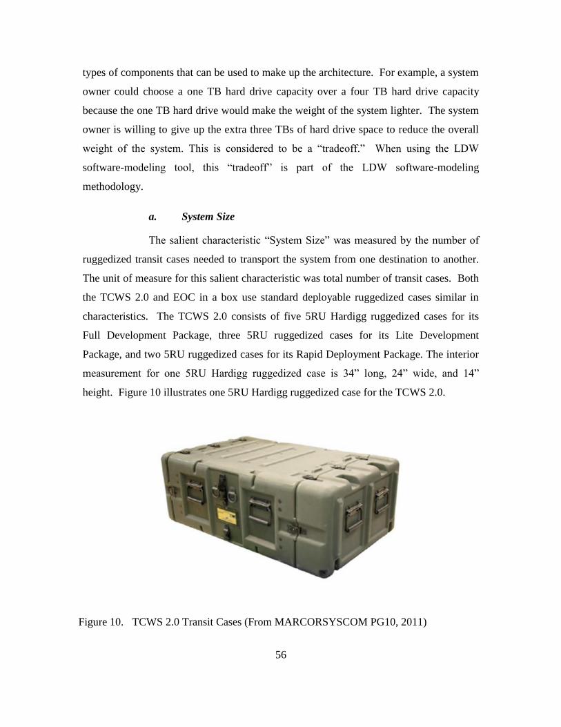
56
types of components that can be used to make up the architecture. For example, a system
owner could choose a one TB hard drive capacity over a four TB hard drive capacity
because the one TB hard drive would make the weight of the system lighter. The system
owner is willing to give up the extra three TBs of hard drive space to reduce the overall
weight of the system. This is considered to be a “tradeoff.” When using the LDW
software-modeling tool, this “tradeoff” is part of the LDW software-modeling
methodology.
a. System Size
The salient characteristic “System Size” was measured by the number of
ruggedized transit cases needed to transport the system from one destination to another.
The unit of measure for this salient characteristic was total number of transit cases. Both
the TCWS 2.0 and EOC in a box use standard deployable ruggedized cases similar in
characteristics. The TCWS 2.0 consists of five 5RU Hardigg ruggedized cases for its
Full Development Package, three 5RU ruggedized cases for its Lite Development
Package, and two 5RU ruggedized cases for its Rapid Deployment Package. The interior
measurement for one 5RU Hardigg ruggedized case is 34” long, 24” wide, and 14”
height. Figure 10 illustrates one 5RU Hardigg ruggedized case for the TCWS 2.0.
Figure 10. TCWS 2.0 Transit Cases (From MARCORSYSCOM PG10, 2011)
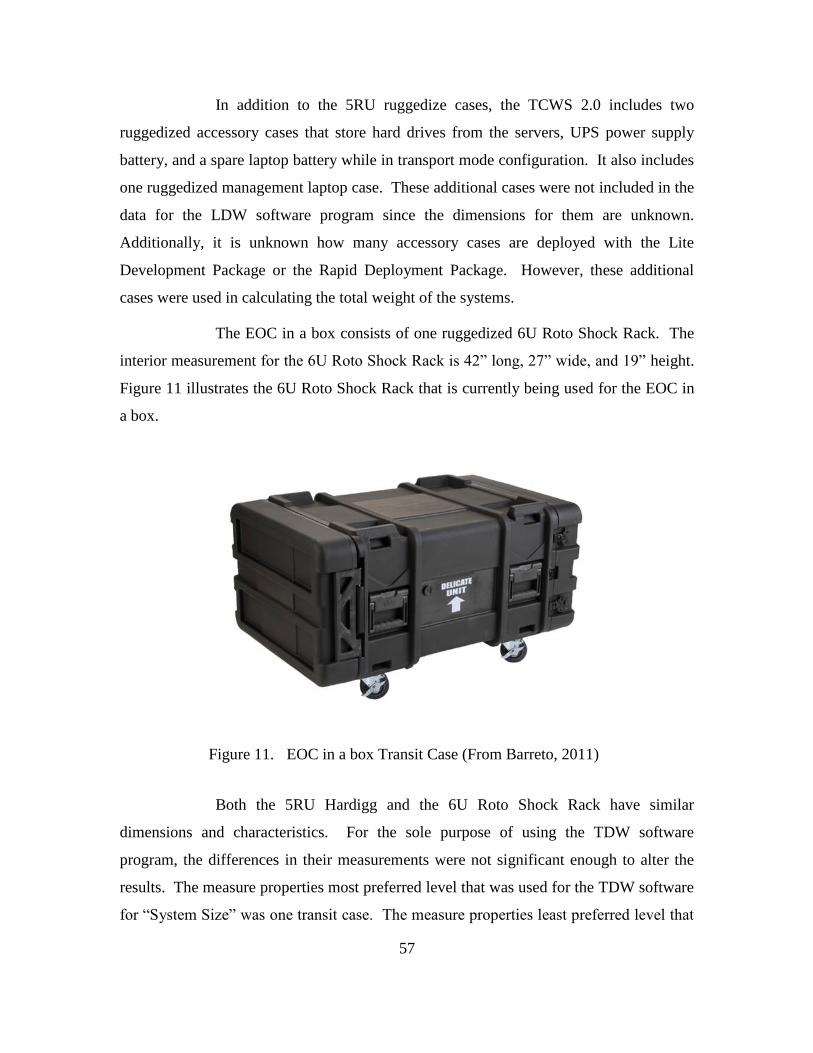
57
In addition to the 5RU ruggedize cases, the TCWS 2.0 includes two
ruggedized accessory cases that store hard drives from the servers, UPS power supply
battery, and a spare laptop battery while in transport mode configuration. It also includes
one ruggedized management laptop case. These additional cases were not included in the
data for the LDW software program since the dimensions for them are unknown.
Additionally, it is unknown how many accessory cases are deployed with the Lite
Development Package or the Rapid Deployment Package. However, these additional
cases were used in calculating the total weight of the systems.
The EOC in a box consists of one ruggedized 6U Roto Shock Rack. The
interior measurement for the 6U Roto Shock Rack is 42” long, 27” wide, and 19” height.
Figure 11 illustrates the 6U Roto Shock Rack that is currently being used for the EOC in
a box.
Figure 11. EOC in a box Transit Case (From Barreto, 2011)
Both the 5RU Hardigg and the 6U Roto Shock Rack have similar
dimensions and characteristics. For the sole purpose of using the TDW software
program, the differences in their measurements were not significant enough to alter the
results. The measure properties most preferred level that was used for the TDW software
for “System Size” was one transit case. The measure properties least preferred level that

58
was used in the TDW software was seven transit cases. These goals were based off of
having the smallest logistical footprint in a deployed environment. The tradeoff for
“System Size” is that the fewer transit cases used would result in fewer resources
available for use in the cloud computing architecture or more transit cases would results
in an increased number of resources available for the architecture.
b. System Weight
The salient characteristic “System Weight” was evaluated by adding up
the total weight of the system. The units of measure for this salient characteristic were
the total number of pounds that the system weighed. The total weight for the TCWS 2.0
Full Development Package was approximately 918 pounds. This was calculated by
adding up the Server Network Module 1, Server Network Module 2, storage case, UPS 1,
UPS 2, accessory case 1, accessory case 2, and laptop case. Table 1 represents the
TCWS 2.0 system weight per transit case.
Table 1. TCWS 2.0 System Weight Per Transit Case (From MARCORSYSCOM,
2011)
Note that for the following two TCWS 2.0 packages, the Lite Development Package and
the Rapid Deployment Package, estimates were made because the makeup of components
for these two systems are not definitive and can vary depending on mission requirements.
The estimated total weight for the TCWS 2.0 Lite Development Package
was estimated approximately 541 pounds. Adding up the weight of the Server Module 1,
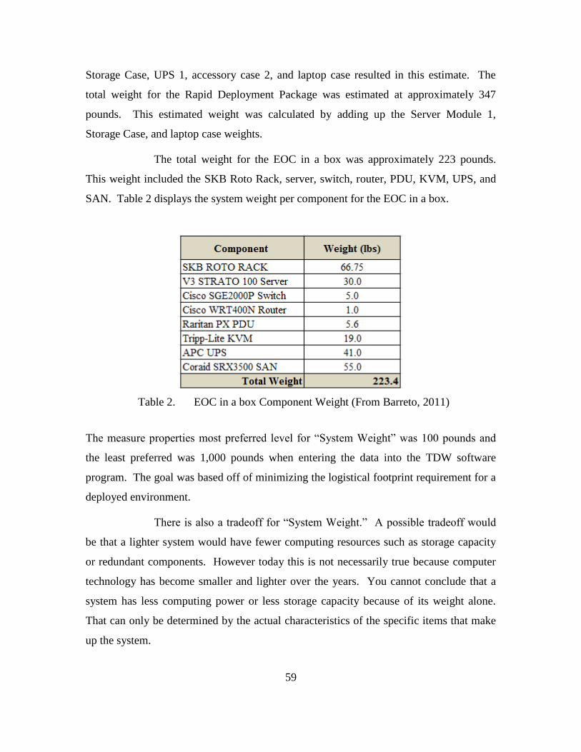
59
Storage Case, UPS 1, accessory case 2, and laptop case resulted in this estimate. The
total weight for the Rapid Deployment Package was estimated at approximately 347
pounds. This estimated weight was calculated by adding up the Server Module 1,
Storage Case, and laptop case weights.
The total weight for the EOC in a box was approximately 223 pounds.
This weight included the SKB Roto Rack, server, switch, router, PDU, KVM, UPS, and
SAN. Table 2 displays the system weight per component for the EOC in a box.
Table 2. EOC in a box Component Weight (From Barreto, 2011)
The measure properties most preferred level for “System Weight” was 100 pounds and
the least preferred was 1,000 pounds when entering the data into the TDW software
program. The goal was based off of minimizing the logistical footprint requirement for a
deployed environment.
There is also a tradeoff for “System Weight.” A possible tradeoff would
be that a lighter system would have fewer computing resources such as storage capacity
or redundant components. However today this is not necessarily true because computer
technology has become smaller and lighter over the years. You cannot conclude that a
system has less computing power or less storage capacity because of its weight alone.
That can only be determined by the actual characteristics of the specific items that make
up the system.
60
c. Storage Capacity
The salient characteristic “Storage Capacity” was evaluated by the amount
of unformatted raw storage available for use by the system. The unit of measure that was
used for this salient characteristic was in Terabytes. The capacity for the TCWS 2.0 Full
Development Package version was given to be 20 TB of raw data storage. Similar to the
weight characteristic of the Lite Development Package and Rapid Deployment Package,
the actual amount of raw data storage is not known since the different versions can be
scaled to meet mission requirements. Since the storage module was included in both the
size and weight calculations, the two smaller version of TCWS 2.0 were given the storage
capacity of 20 TB.
The amount of raw data storage for the EOC in a box was 20 TB, which
can also be scaled down to meet mission requirements. The measure properties preferred
level for “Storage Capacity” was 25 TBs and the least preferred level was 1 TB. This
goal was based off of the capacity/elasticity system requirement where the proposed
cloud computing architecture would support 50 or fewer users. The tradeoff for this
salient characteristic could be that an increase in amount of storage could possibly cause
a system to increase in weight and/or increase in the total amount of power consumption.
However, similar to “System Weight” this tradeoff may not necessarily be true due to
recent technology. However, the other tradeoff of using newer technology would be an
increase in price for the different components.
d. Power Requirements
The salient characteristic “Power Requirement” was evaluated by looking
at the total number of watts that it takes to power the cloud computing architecture.
According to MARCORSYSCOM PG10 (2011), the system power requirement for the
TCWS 2.0 Full Development Package is 2,734 watts. Table 3 depicts the measured
power requirements for the TCWS 2.0 Full Development Package and is broken down by
components.
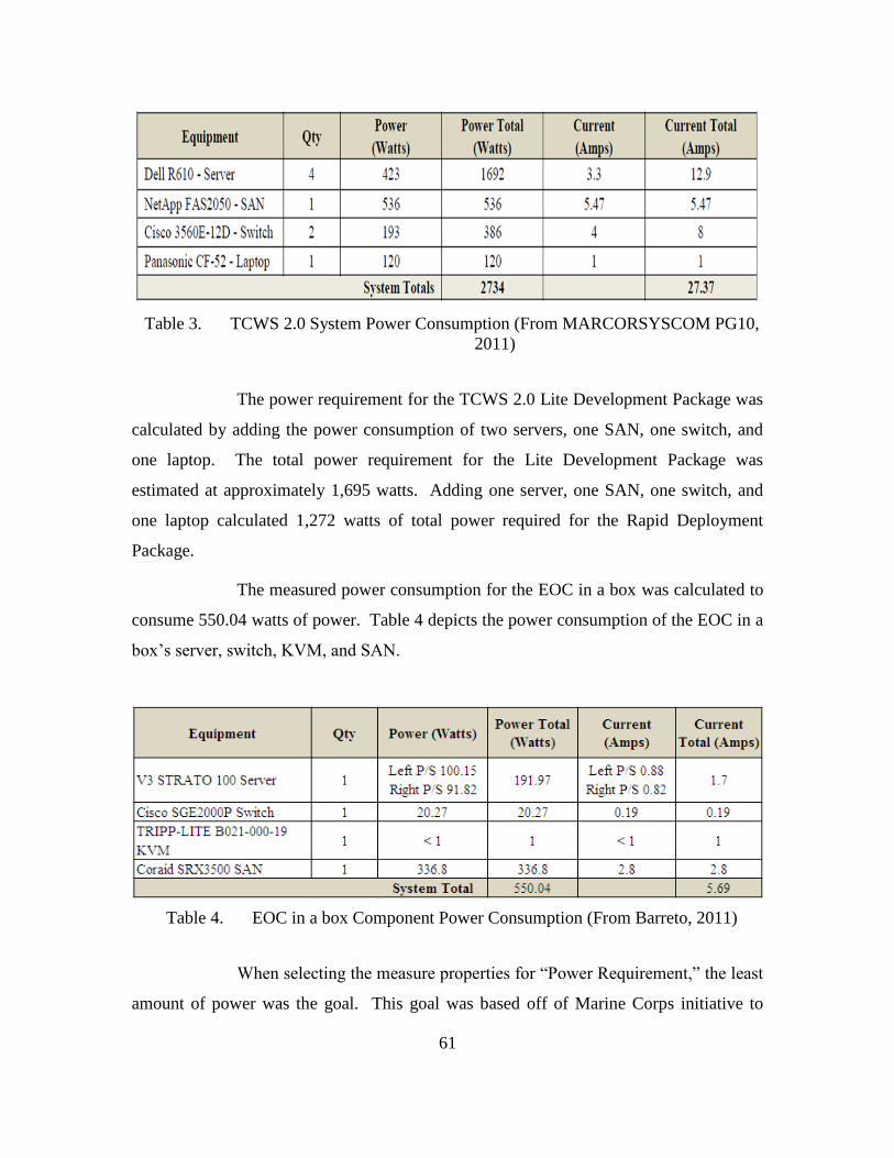
61
Table 3. TCWS 2.0 System Power Consumption (From MARCORSYSCOM PG10,
2011)
The power requirement for the TCWS 2.0 Lite Development Package was
calculated by adding the power consumption of two servers, one SAN, one switch, and
one laptop. The total power requirement for the Lite Development Package was
estimated at approximately 1,695 watts. Adding one server, one SAN, one switch, and
one laptop calculated 1,272 watts of total power required for the Rapid Deployment
Package.
The measured power consumption for the EOC in a box was calculated to
consume 550.04 watts of power. Table 4 depicts the power consumption of the EOC in a
box’s server, switch, KVM, and SAN.
Table 4. EOC in a box Component Power Consumption (From Barreto, 2011)
When selecting the measure properties for “Power Requirement,” the least
amount of power was the goal. This goal was based off of Marine Corps initiative to
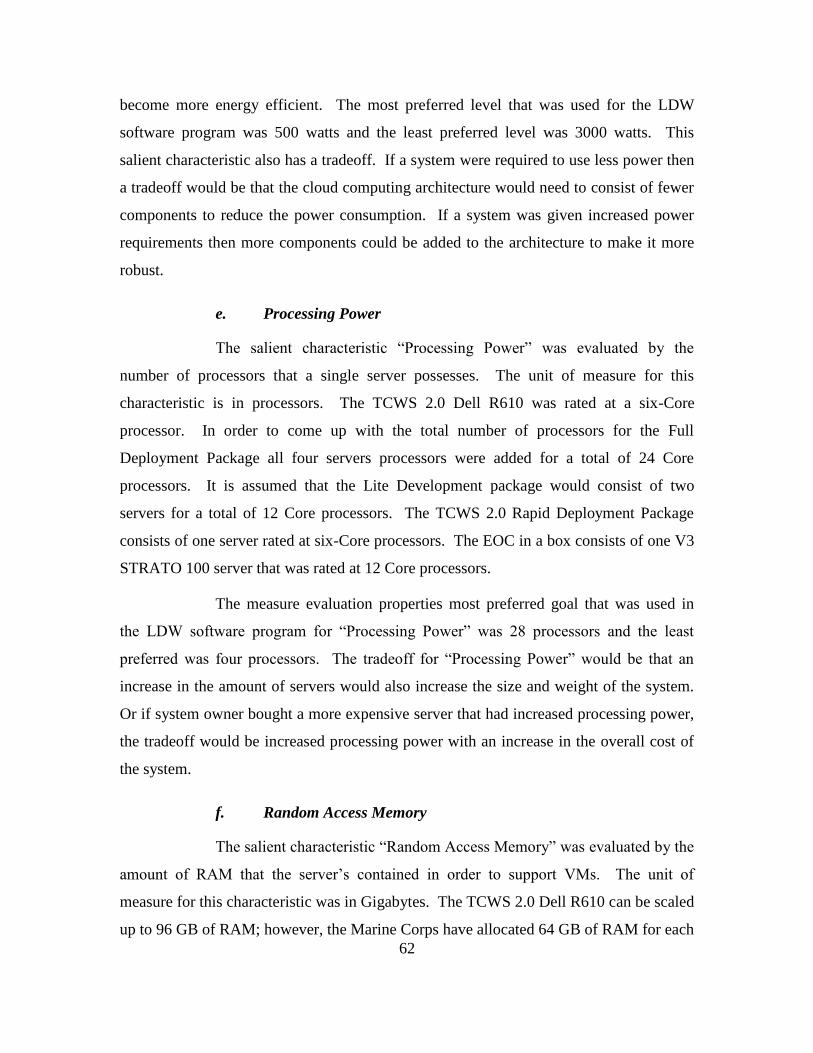
62
become more energy efficient. The most preferred level that was used for the LDW
software program was 500 watts and the least preferred level was 3000 watts. This
salient characteristic also has a tradeoff. If a system were required to use less power then
a tradeoff would be that the cloud computing architecture would need to consist of fewer
components to reduce the power consumption. If a system was given increased power
requirements then more components could be added to the architecture to make it more
robust.
e. Processing Power
The salient characteristic “Processing Power” was evaluated by the
number of processors that a single server possesses. The unit of measure for this
characteristic is in processors. The TCWS 2.0 Dell R610 was rated at a six-Core
processor. In order to come up with the total number of processors for the Full
Deployment Package all four servers processors were added for a total of 24 Core
processors. It is assumed that the Lite Development package would consist of two
servers for a total of 12 Core processors. The TCWS 2.0 Rapid Deployment Package
consists of one server rated at six-Core processors. The EOC in a box consists of one V3
STRATO 100 server that was rated at 12 Core processors.
The measure evaluation properties most preferred goal that was used in
the LDW software program for “Processing Power” was 28 processors and the least
preferred was four processors. The tradeoff for “Processing Power” would be that an
increase in the amount of servers would also increase the size and weight of the system.
Or if system owner bought a more expensive server that had increased processing power,
the tradeoff would be increased processing power with an increase in the overall cost of
the system.
f. Random Access Memory
The salient characteristic “Random Access Memory” was evaluated by the
amount of RAM that the server’s contained in order to support VMs. The unit of
measure for this characteristic was in Gigabytes. The TCWS 2.0 Dell R610 can be scaled
up to 96 GB of RAM; however, the Marine Corps have allocated 64 GB of RAM for each
63
Dell R610 server. Each server’s RAM was added in order to come up with 256 GBs of
RAM available for the Full Development Package TCWS 2.0. For the Lite Development
package the RAM for two servers were added to get a total of 128 GBs of RAM. The
TCWS 2.0 Rapid Deployment Package consists of one server, and as stated above, it was
rated at 64 GBs of RAM. The EOC in a box consists of one V3 STRATO 100 server that
was rated at 128 GBs of RAM.
When selecting the goal for “Random Access Memory,” the greater
amount of RAM was considered optimal, as it would allow for increased computing
power. The most preferred level of RAM that was used for the LDW software program
was 288 GBs and the least preferred level was 32 GBs. The tradeoff for this salient
characteristic would be an increase in RAM could provide more computing power for the
cloud computing architecture. However, the additional RAM could increase the overall
cost of the system.
g. Local Area Network / Wide Area Network Access
The salient characteristic “LAN/WAN” access for both the TCWS 2.0 and
the EOC in a box were very similar. TCWS 2.0 Full Development Package, Lite
Development Package, and Rapid Deployment Package all use Cisco 3560E-12D
switches. The Full Development Package uses two Cisco 3560E-12D switches and it is
assumed that both the Lite Development Package and the Rapid Deployment Package
would deploy with only one switch each. The EOC in a box consists of one Cisco
SGE2000P switch.
The measure properties most preferred goal that was used for the LDW
software program was one network switch and the least preferred was three network
switches. This goal was based off of the requirement to have an architecture that requires
minimal power. It was also based off of the requirement for a small logistical footprint in
a deployed environment. The tradeoff for this salient characteristic is that the fewer
switches that a unit deploys with would result in less switching capabilities for the cloud
computing architecture. However, the fewer switches that are deployed would decrease
the weight and size of the overall system. Note that the TCWS 2.0 does not use wireless
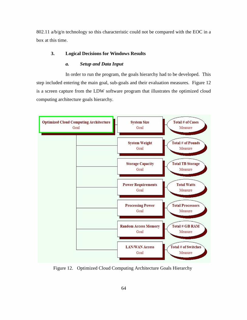
64
802.11 a/b/g/n technology so this characteristic could not be compared with the EOC in a
box at this time.
3. Logical Decisions for Windows Results
a. Setup and Data Input
In order to run the program, the goals hierarchy had to be developed. This
step included entering the main goal, sub-goals and their evaluation measures. Figure 12
is a screen capture from the LDW software program that illustrates the optimized cloud
computing architecture goals hierarchy.
Figure 12. Optimized Cloud Computing Architecture Goals Hierarchy
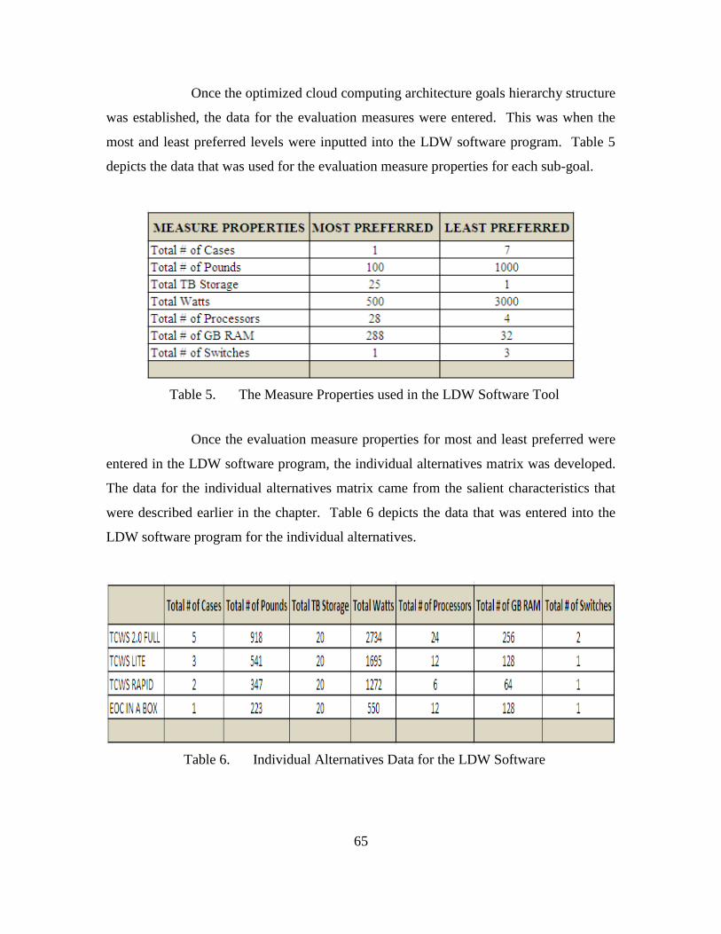
65
Once the optimized cloud computing architecture goals hierarchy structure
was established, the data for the evaluation measures were entered. This was when the
most and least preferred levels were inputted into the LDW software program. Table 5
depicts the data that was used for the evaluation measure properties for each sub-goal.
Table 5. The Measure Properties used in the LDW Software Tool
Once the evaluation measure properties for most and least preferred were
entered in the LDW software program, the individual alternatives matrix was developed.
The data for the individual alternatives matrix came from the salient characteristics that
were described earlier in the chapter. Table 6 depicts the data that was entered into the
LDW software program for the individual alternatives.
Table 6. Individual Alternatives Data for the LDW Software
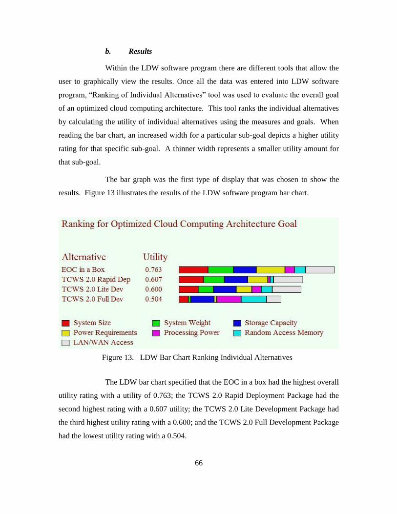
66
b. Results
Within the LDW software program there are different tools that allow the
user to graphically view the results. Once all the data was entered into LDW software
program, “Ranking of Individual Alternatives” tool was used to evaluate the overall goal
of an optimized cloud computing architecture. This tool ranks the individual alternatives
by calculating the utility of individual alternatives using the measures and goals. When
reading the bar chart, an increased width for a particular sub-goal depicts a higher utility
rating for that specific sub-goal. A thinner width represents a smaller utility amount for
that sub-goal.
The bar graph was the first type of display that was chosen to show the
results. Figure 13 illustrates the results of the LDW software program bar chart.
Figure 13. LDW Bar Chart Ranking Individual Alternatives
The LDW bar chart specified that the EOC in a box had the highest overall
utility rating with a utility of 0.763; the TCWS 2.0 Rapid Deployment Package had the
second highest rating with a 0.607 utility; the TCWS 2.0 Lite Development Package had
the third highest utility rating with a 0.600; and the TCWS 2.0 Full Development Package
had the lowest utility rating with a 0.504.
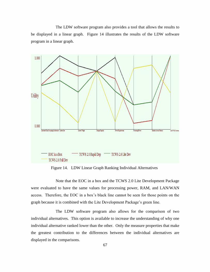
67
The LDW software program also provides a tool that allows the results to
be displayed in a linear graph. Figure 14 illustrates the results of the LDW software
program in a linear graph.
Figure 14. LDW Linear Graph Ranking Individual Alternatives
Note that the EOC in a box and the TCWS 2.0 Lite Development Package
were evaluated to have the same values for processing power, RAM, and LAN/WAN
access. Therefore, the EOC in a box’s black line cannot be seen for those points on the
graph because it is combined with the Lite Development Package’s green line.
The LDW software program also allows for the comparison of two
individual alternatives. This option is available to increase the understanding of why one
individual alternative ranked lower than the other. Only the measure properties that make
the greatest contribution to the differences between the individual alternatives are
displayed in the comparisons.
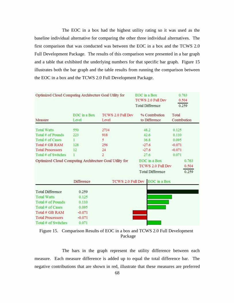
68
The EOC in a box had the highest utility rating so it was used as the
baseline individual alternative for comparing the other three individual alternatives. The
first comparison that was conducted was between the EOC in a box and the TCWS 2.0
Full Development Package. The results of this comparison were presented in a bar graph
and a table that exhibited the underlying numbers for that specific bar graph. Figure 15
illustrates both the bar graph and the table results from running the comparison between
the EOC in a box and the TCWS 2.0 Full Development Package.
Figure 15. Comparison Results of EOC in a box and TCWS 2.0 Full Development
Package
The bars in the graph represent the utility difference between each
measure. Each measure difference is added up to equal the total difference bar. The
negative contributions that are shown in red, illustrate that these measures are preferred
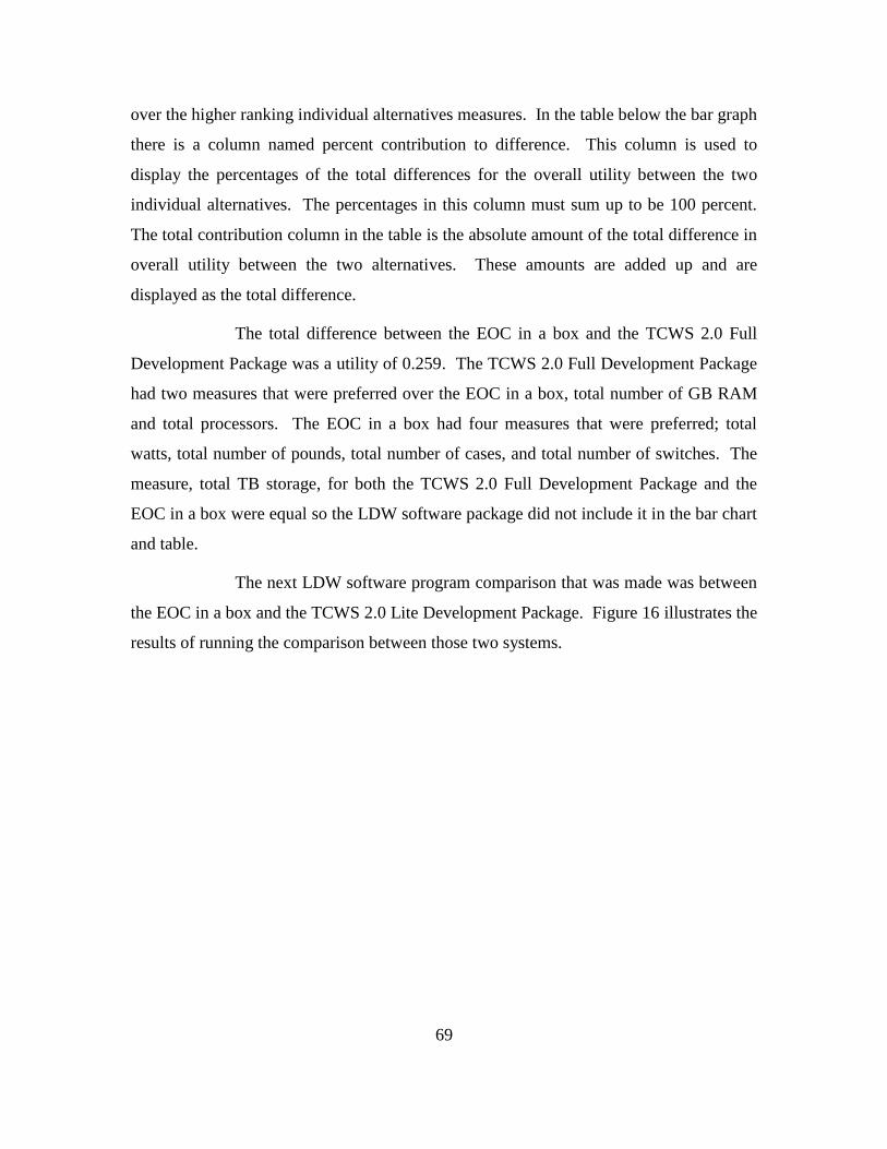
69
over the higher ranking individual alternatives measures. In the table below the bar graph
there is a column named percent contribution to difference. This column is used to
display the percentages of the total differences for the overall utility between the two
individual alternatives. The percentages in this column must sum up to be 100 percent.
The total contribution column in the table is the absolute amount of the total difference in
overall utility between the two alternatives. These amounts are added up and are
displayed as the total difference.
The total difference between the EOC in a box and the TCWS 2.0 Full
Development Package was a utility of 0.259. The TCWS 2.0 Full Development Package
had two measures that were preferred over the EOC in a box, total number of GB RAM
and total processors. The EOC in a box had four measures that were preferred; total
watts, total number of pounds, total number of cases, and total number of switches. The
measure, total TB storage, for both the TCWS 2.0 Full Development Package and the
EOC in a box were equal so the LDW software package did not include it in the bar chart
and table.
The next LDW software program comparison that was made was between
the EOC in a box and the TCWS 2.0 Lite Development Package. Figure 16 illustrates the
results of running the comparison between those two systems.
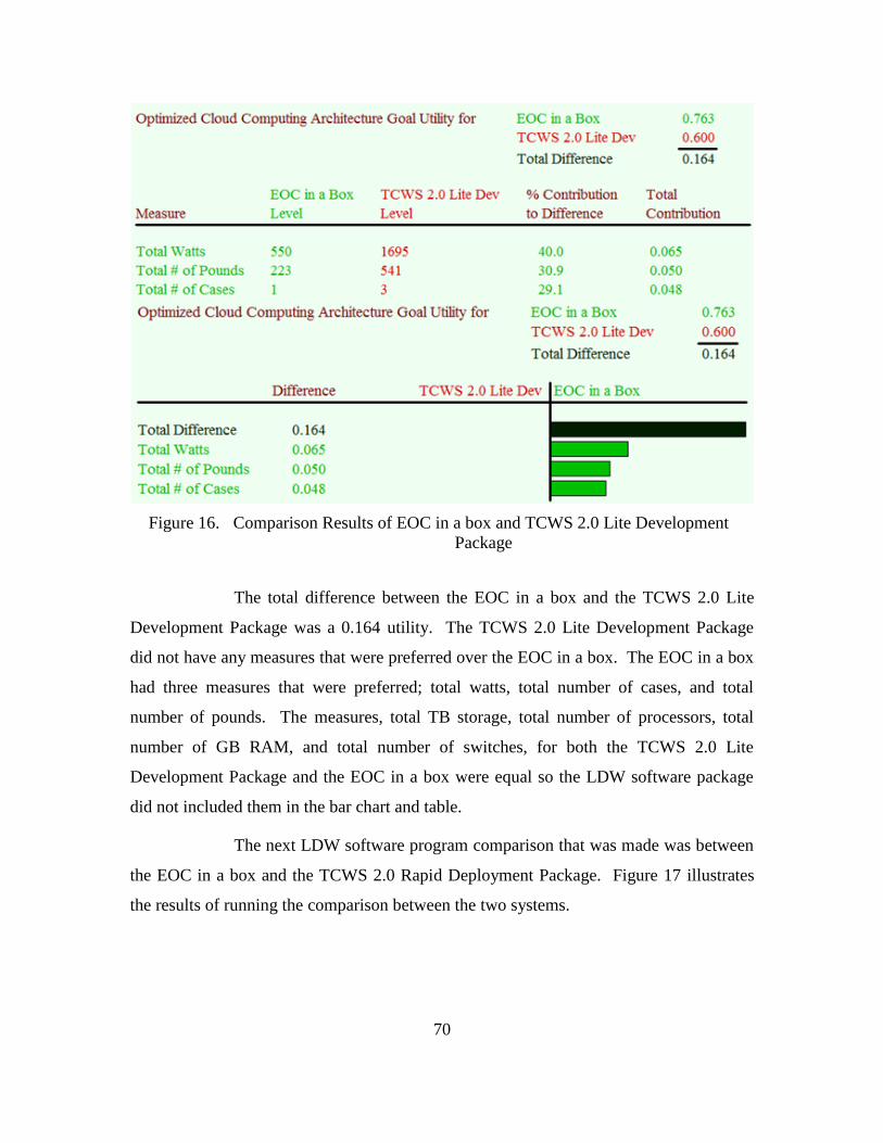
70
Figure 16. Comparison Results of EOC in a box and TCWS 2.0 Lite Development
Package
The total difference between the EOC in a box and the TCWS 2.0 Lite
Development Package was a 0.164 utility. The TCWS 2.0 Lite Development Package
did not have any measures that were preferred over the EOC in a box. The EOC in a box
had three measures that were preferred; total watts, total number of cases, and total
number of pounds. The measures, total TB storage, total number of processors, total
number of GB RAM, and total number of switches, for both the TCWS 2.0 Lite
Development Package and the EOC in a box were equal so the LDW software package
did not included them in the bar chart and table.
The next LDW software program comparison that was made was between
the EOC in a box and the TCWS 2.0 Rapid Deployment Package. Figure 17 illustrates
the results of running the comparison between the two systems.
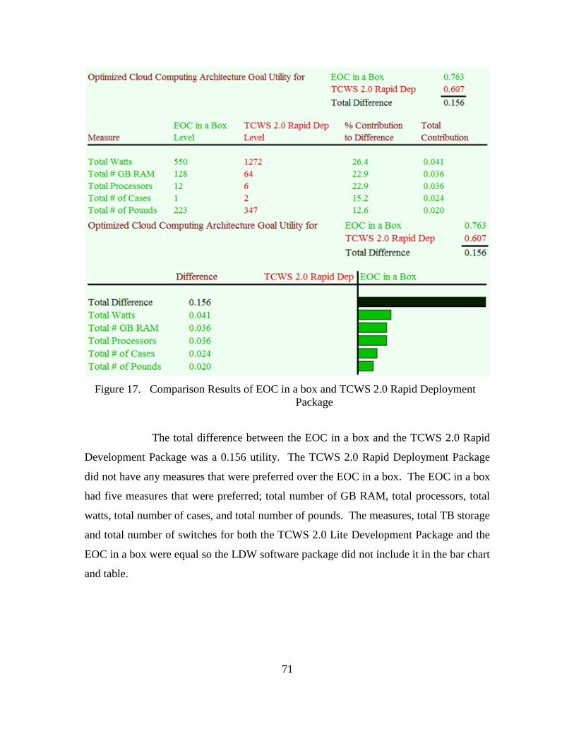
71
Figure 17. Comparison Results of EOC in a box and TCWS 2.0 Rapid Deployment
Package
The total difference between the EOC in a box and the TCWS 2.0 Rapid
Development Package was a 0.156 utility. The TCWS 2.0 Rapid Deployment Package
did not have any measures that were preferred over the EOC in a box. The EOC in a box
had five measures that were preferred; total number of GB RAM, total processors, total
watts, total number of cases, and total number of pounds. The measures, total TB storage
and total number of switches for both the TCWS 2.0 Lite Development Package and the
EOC in a box were equal so the LDW software package did not include it in the bar chart
and table.
72
C. PROPOSED CLOUD COMPUTING ARCHITECTURE
In this section we present a cloud computing architecture that “best” supports
expeditionary logistics for the Marine Corps. Prior to introducing the architecture it is
important to describe the guidelines and considerations that lead to the creation of the
proposed architecture.
1. Cloud Computing Architecture Guidelines and Considerations
Design of the proposed cloud computing architecture was developed using the
principles from the Federal, DoD, and Marine Corps cloud computing guiding
documents. More specifically the Federal and DoD documents included the 25 Point
Implementation Plan to Reform Federal Information Technology Management, DoD
Cloud Computing Strategy, DoD Enterprise Cloud Environment, DoD JIE, and DoDAF.
The background and strategies for these guiding documents were presented in Chapter I.
In addition to the Federal and DoD documents, the Marine Corps Cloud
Computing Environment Strategy, MCEITS, and Tactical Service Oriented Architecture
were used as guiding principles. These were used to ensure that the proposed
architecture would align with the Marine Corps’ current C4 and Logistic systems. In
proposing the cloud computing architecture it was essential that a SOA method be
established and standard networking protocols be used to ensure that the system was
scalable, flexible, and interoperable with the MCEITS, MCEN and TSOA described in
Chapter II.
2. Cloud Computing Architecture Service Model
The proposed cloud computing architecture will offer deployed Marine Corps
units an IaaS service model design. The cloud computing architecture will provide units
the fundamental computing resources such as virtual desktops, applications, data, and
network-accessible storage in a DIL network status. This autonomous cloud computing
architecture will possess the capability to host and run Marine Corps specific software
and applications depending on the mission requirements. More specifically, the proposed
73
cloud computing architecture will be able to host data sets, analytic tools, and approved
MLS2 software and applications such as the GCSS-MC.
From the user perspective, the proposed cloud computing architecture will
provide Marines with a SaaS that will allow the use of web-based services through
approved client devices.
3. Cloud Computing Architecture
The results from the LDW software program displayed that the HFN EOC in a
box had the highest utility rating based on the defined goals and measures. Based on the
requirements outlined earlier, the EOC in a box was used as the baseline cloud computing
architecture from which to develop the proposed cloud computing architecture. During
the development process, critical goals for improving the EOC in a box were identified
based on the utility rankings of the salient characteristics that were presented in the LDW
software program results. The top two utility rankings from the LDW software program
were system size and system weight.
The main goals for the proposed cloud computing architecture were to make the
system smaller and lighter than the current EOC in a box. In addition, every effort was
made to ensure that the system, while supporting the main goals, maintained or lowered
its power consumption and provided sufficient computing and storage resources to
accomplish the mission. Each component, based on their salient characteristics was
chosen in support for main goals. The following is the proposed cloud computing
architecture that “best” supports expeditionary logistics based on system requirements
and the LDW software results:
3U Ruggedized Case
1U Four Bay SAN
1U Server System that consists of
- 12 CPU cores
- 8 TB SSD Local Storage
74
- 128 GB RAM
- VMware ESX or ESXi Hypervisor
1U 24 Port Gigabit PoE Switch
Wireless Access Point / Router
External 1000 watt UPS in Ruggedized Case
Power Distribution Unit for analyzing and controlling power
Laptop Computer for system management and access
This architecture will be referred to as the United States Marine Corps Expeditionary
Logistics Cloud (USMCELC) architecture for the remainder of the thesis.
In order to achieve the goals, tradeoffs between salient characteristics needed to
occur. Tradeoffs such as a decrease in transport case size, a decrease in SAN storage
size, elimination of the KVM, and removal of the UPS from the transport case. These
tradeoffs allowed these goals to be achieved. These tradeoffs will be explained in detail
when each component is described in the succeeding paragraphs.
4. Cloud Computing Architecture Components
a. Ruggedized Case
The objective for choosing a smaller ruggedized case was to decrease the
overall size of the USMCELC architecture to ensure that a deployed unit maintained the
smallest logistical footprint possible. The decrease in ruggedized case size would also
support the goal to reduce the overall weight of the USMCELC architecture, which
would help increase the systems mobility. The EOC in a box consisted of one 6U
ruggedized case and in order to reduce the size, it was proposed that one 3U-ruggedized
case be used for the USMCELC architecture. A 3U-ruggedized case would decrease the
size of the transport case to roughly 40” long, 24.50” width, and 12.25” height. In
addition, reducing the size of the transport case to a 3U-ruggedized case decreased the
overall weight of the system by 7.75 pounds.
75
This is the first tradeoff for the USMCELC architecture as the 3U-
ruggedized case limits the amount of components that can be mounted in the case.
However, the case reduced dimensions would give leaders additional options on how to
get the system to its deployed destination. For example, this smaller case could be
checked in as luggage at an airport if a small unit detachment were required to fly to their
destination on commercial airlines.
The proposed 3U-ruggedized case would be used to mount the switch and
PDU in a single shared 1U slot, the server in another 1U slot, and the SAN in the
remaining 1U slot. The UPS that was previously located in the EOC in a box’s 6U
ruggedized case would be transported and stored in a separate ruggedized case which
would also be suitable for commercial airline travel.
b. Four Bay SAN
It is proposed that the USMCELC architecture reduce the SAN storage
capacity in order to decrease the overall weight of the architecture. The EOC in a box is
equipped with a 2U SAN and depending on drive configuration can store up to 20 TBs of
storage with an approximate weight of 55 pounds. The proposed 1U four bay SAN
would consist of an eight TB hard drive capacity and would weigh approximately 26
pounds. Eight TBs of storage was chosen; however, the four bays in the SAN offers
leaders the capability to increase or decrease storage capacity depending on mission
requirements. The SAN offers each deploying unit the ability to pre-load data, as well as
capture and process data in near real time while deployed and in a partially connected or
disconnected state.
The decrease in SAN storage is the second tradeoff that was required in
order to make the USMCELC architecture lighter. This tradeoff decreased the SAN
storage capacity by 12 TBs; however, it also decreased the overall weight of the SAN by
approximately 29 pounds. Leaders would have to decide if this tradeoff is worth the
decrease in 12 TBs of SAN storage. However, the loss of the 12 TBs of SAN storage
could be compensated for by allocating some of the proposed server’s eight TBs of local
storage space to host local data and applications. The server described in the next section
will provide leaders with that addition option.
76
c. Server System
The objective for processing power was to maintain the same number of
processors that the EOC in the box contains to allow for maximum computing power.
The EOC in a box consists of a single, 1U server that possesses 12 processor cores. It is
proposed that the USMCELC architecture also use a 1U server system that contains 12
processor cores. However, in order to improve the system and possibly provide
additional storage for the reduction in SAN storage, it is proposed that the server possess
eight TBs of SSD local storage. This will give leaders the option to allocate some of the
eight TBs of local storage to host data or applications on the server, depending on
mission requirements. There is no tradeoff here besides the cost of purchasing a server
that has eight TBs of SSD local storage vice the 768 GBs of local storage that the current
EOC in a box possesses.
The EOC in a box’s server contained 128 GBs of RAM. It is proposed
that the 1U server system for the USMCELC architecture also possess a minimum of 128
GBs of RAM. This will provide sufficient memory for the execution of VMware
supporting Microsoft Windows Active Directory Infrastructure, VMs, and other
applications running on the server. The 128 GBs of RAM will support anywhere from 25
to 50 VMs with the use of the VDI. The actual number of VMs depends on how much
RAM a system administrator allocates for each virtual desktop. The industry standard for
a typical 64 bit Windows 7 VM is to allocate it 3 GB of RAM. The RAM in the
proposed 1U server system is scalable and can be increased or decreased depending on
mission requirements. If more users are required for the proposed architecture then
leaders can increase the RAM capacity by simply installing additional RAM modules or
if fewer users are required then the RAM can remain the same or even be decreased
which reduces overall power requirements.
The USMCELC architecture will use virtualization technologies in order
to better support the Marine Corps’ unique, small unit missions. Like the EOC in a box,
the USMCELC architecture will use a VMware ESX or ESXi environment since the
Marine Corps owns an enterprise license for it. The USMCELC architecture will include
the VMware View and ESX server as well as the AD, DNS, and other supporting systems
77
that support user authentication, machine identification and validation, and security. The
proposed architecture will be able to support up to 50 virtual desktops that can be
accessible from laptop computers, pad and tablet computers running Windows, MAC, or
Linux Operating Systems, smartphones, thin clients, or zero clients. The USMCELC
architecture will provide a complete virtualization environment for deploying units.
d. 24 Port Gigabit PoE Switch and Wireless Access Point
The objective for the LAN/WAN access was to maintain the same
network switching capabilities that the EOC in a box possessed. The EOC in a box
contained a 1U 24 port PoE gigabit switch. It is proposed that the USMCELC
architecture also contain a 1U 24 port PoE gigabit switch that has the same switching
capabilities. This will provide the deploying unit the capability to connect computers via
Ethernet cable.
In addition to the network switch, it is proposed that a wireless access
point which supports PoE be implemented with the USMCELC architecture. This would
provide user flexibility to support a mixture of fixed and mobile users in a wider area.
With a wired system, the number of ports on the switch limits the number of users and
cable length limits users flexibility of set up locations. Also, a WAP would reduce the
logistic footprint in an expeditionary environment since system administrators would not
be required to deploy with as much network cables to support the mission requirements.
The WAP would not physically be attached to the ruggedized case but would be stored in
the lid during transportation and deployed to a location which would provide optimal
wireless coverage.
e. Uninterrupted Power Supply
For the USMCELC architecture it is proposed that a separate 1,000 watt
SMART UPS be employed. The EOC in a box currently has an APC SMART UPS 750
UPS that is mounted in the 6U ruggedized transport case. The increase in 250 watts will
provide additional power to ensure that the UPS will provide sufficient backup power and
extend run-time to the USMCELC architecture in case of power outages. Moving the
UPS outside of the ruggedized case will provide leaders with the option of deploying
78
with or without it depending on mission requirements. If leaders determine that it is
required, then having the UPS outside of the ruggedized case will also facilitate weight
distribution when deploying the USMCELC architecture; if it is determine that it is not
required then it can be left behind.
The tradeoff off for increasing the UPS wattage capacity could be that the
weight of the overall system could increase. However, after reviewing several different
1,000 watts UPS systems on the Internet, the weights can vary from 40 to 60 pounds. We
propose the UPS system for the USMCELC architecture maintain the same weight
characteristics as the EOC in a box at approximately 41 pounds. Another tradeoff for the
UPS system is that if it is moved outside of the ruggedized transport case that there is an
additional item to carry when deploying the USMCELC architecture.
f. Power Distribution Unit
The objective for including the PDU was to maintain the same capabilities
as the EOC in a box. The EOC in a box uses a PDU that can provide system
administrators with accurate power consumption measurements. It is a tool that can
determine which devices need the most power and what systems can be reduced when
power requirements need to be conserved. The PDU also has the capability of staging
how the outlets are powered on and off. This reduces the load on the power system
during the boot cycle. For example, the SAN can be cycled on automatically and allowed
to complete its boot process before the server boots. It is proposed that the USMCELC
architecture use a PDU that has the same characteristics as the EOC in a box’s PDU.
This will allow the PDU and switch to share a single 1U slot maximizing the space within
the 3U ruggedized transport case.
g. Laptop Computer
It is proposed that a laptop computer be added to the USMCELC
architecture in order to eliminate the KVM from the 3U ruggedized transport case. The
laptop would serve as the management console and also as a workstation. This would
reduce the weight of the architecture by 19 pounds. By incorporating a laptop, system
administrators can connect to the USMCELC architecture via a universal serial bus
79
(USB) device to manage the server and eliminate the requirement for a KVM. The
tradeoff for adding a laptop and removing the KVM from the architecture would be that a
system administrator would need to deploy either a regular laptop in a ruggedized case or
a ruggedized laptop in order to manage the server. An average ruggedized laptop usually
weighs approximately 6 pounds; therefore this tradeoff reduced the overall weight of the
cloud computing architecture by 13 pounds.
h. Cloud Computing Architecture Weight
Equipping a deploying unit with a lighter and mobile cloud computing
architecture was one of the main goals for the proposed architecture. This would benefit
units that may be required to deploy on a moment’s notice or that require frequent
displacements once deployed. Through modeling and analysis of salient characteristic
tradeoffs, approximately 49 pounds of weight was reduced for the USMCELC
architecture in comparison to the EOC in a box. The following are the calculations for
the weight reductions:
Reducing the size of the 6U ruggedized transport case to a 3U
ruggedized transport case decreased the overall weight of the
system by 7.75 pounds.
Replacing the 2U SAN to a 1U SAN decreased the architectures
weight by 29 pounds.
Using an USB device connected to a laptop computer eliminated
the 19-pound KVM but added a six-pound laptop. The net
reduction was 13 pounds.
The total weight of the entire USMCELC architecture including the UPS
was approximately 174 pounds. However, if it was determined that the UPS was not
needed the weight of the USMCELC architecture would be approximately 133 pounds.
Table 7 depicts the system weight per component of the USMCELC architecture.
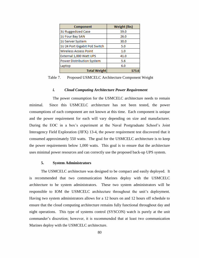
80
Table 7. Proposed USMCELC Architecture Component Weight
i. Cloud Computing Architecture Power Requirement
The power consumption for the USMCELC architecture needs to remain
minimal. Since this USMCELC architecture has not been tested, the power
consumptions of each component are not known at this time. Each component is unique
and the power requirement for each will vary depending on size and manufacturer.
During the EOC in a box’s experiment at the Naval Postgraduate School’s Joint
Interagency Field Exploration (JIFX) 13-4, the power requirement test discovered that it
consumed approximately 550 watts. The goal for the USMCELC architecture is to keep
the power requirements below 1,000 watts. This goal is to ensure that the architecture
uses minimal power resources and can correctly use the proposed back-up UPS system.
5. System Administrators
The USMCELC architecture was designed to be compact and easily deployed. It
is recommended that two communication Marines deploy with the USMCELC
architecture to be system administrators. These two system administrators will be
responsible to IOM the USMCELC architecture throughout the unit’s deployment.
Having two system administrators allows for a 12 hours on and 12 hours off schedule to
ensure that the cloud computing architecture remains fully functional throughout day and
night operations. This type of systems control (SYSCON) watch is purely at the unit
commander’s discretion; however, it is recommended that at least two communication
Marines deploy with the USMCELC architecture.
81
6. Satellite Connectivity
As real world missions arise and Marine Corps units deploy, it is crucial that the
USMCELC architecture be set up with an appropriate satellite terminal. The satellite
terminal must be able to connect to the MCEN and allow user access to the Marine Corps
PCCE. Although the USMCELC was designed to function autonomously during a DIL
network state, a high performing satellite terminal will complement the architecture and
make it a more effective system.
The Marine Corps currently has the SWAN-D Terminal that can operate in the
Ku-Band and Ka-Band frequency range and provides secure and non-secure
communications. Although this system has proven to be successful as a fly-away
portable terminal, it currently consists of five ruggedized transit cases, two outdoor cases
and three indoor cases. Possessing five transit cases limits the mobility of the satellite
terminal and adds additional logistical requirements to deploy this satellite terminal.
However, the SWAN-D terminal is an option that the Marine Corps has to deploy with
the USMCELC architecture.
Another option could be a very-small-aperture terminal (VSAT) that has recently
grown in popularity. The VSATs are known to be small, possess low power
consumption, and have become a necessity for Special Forces, unmanned aerial vehicles
and other DoD entities requiring lightweight equipment to be able to move quickly
(Defense Systems, 2012). The VSATs are small, lightweight, and extremely mobile,
which are key issues for the USMCELC architecture. Recently, at the Naval
Postgraduate School’s JIFX 13-4, the EOC in a box deployed a VSAT satellite for the
four day experiment. The entire satellite system fit into one transport case that was
smaller and lighter than the 6U ruggedized transit case that held the EOC in a box.
Throughout the experiment, the VSAT provided users with Internet access and C2 web
applications with five megabyte upload and 15 megabyte download speeds.
It is proposed that a satellite system with similar characteristics as the VSAT be
used with the USMCELC architecture. This will ensure that the entire USMCELC
architecture, including the means to access the satellite and the Internet, remains as
mobile as possible and can be easily deployed at a moment’s notice in order to support
the Marine Corp’s unique, small unit missions.

82
THIS PAGE INTENTIONALLY LEFT BLANK
83
V. CONCLUSION AND RECOMMENDATIONS
A. CONCLUSION
Cloud computing is a relatively new and promising paradigm that continues to
evolve in both the private and public sectors. Corporations in the private sector have
benefited from cloud computing technologies through increased efficiencies and cost
saving. The DoD recently adopted an enterprise first approach and has begun the
implementation of an Enterprise Cloud Environment in order to enhance the department’s
current IT infrastructure. This Enterprise Cloud Environment will facilitate and support
the DoD JIE and DoDAF goals of a unified information and IT environment.
The Marine Corps published its PCCE Strategy, which aligns with the DoD
Enterprise Cloud Environment. The PCCE’s goal was to align the Marine Corps’
enterprise processes for both SEs and forward deployed forces. When a Marine Corps
unit deploys to an austere environment, Marines are required to IOM communication
networks in order to provide commanders with effective C2 and Logistic Services
capabilities. The Marine Corps currently has the TCWS 2.0 that provides the MAGTF
with standardized platforms to support web-enable, virtualized, deployable information
management for collaborative and C2 requirements. Similar to the Marine Corps, the
Hastily Formed Network, which was coined at the Naval Postgraduate School, is required
to establish a communications architecture that supports a network of organizations. As
part of the HFN IPC3 project, the EOC in a box is a part of a proof-of-concept deployable
SOS/IaaS platform solution for HA/DR efforts. The second iteration of the EOC in a box
is currently under development under a Department of Homeland Security (DHS),
science and technology (S&T) sponsored program, and will be sent to the DHS
commercialization department in the first quarter of Fiscal Year 2014 where it will
become a COTS system on the GSA schedule for first responders.
This study focused on all aspects of the Marine Corps and Naval Postgraduate
School HFN cloud computing architectures, which support C2 and collaborative
requirements. More specifically, this study used a constructive research approach that
84
used existing technologies, the three TCWS 2.0 packages and EOC in a box, to define the
capabilities, required standards, and the conditions under which to employ a cloud
computing architecture that will support enhanced logistic systems in a deployed
environment. The LDW software program was used to analyze and compare the three
different TCWS 2.0s and the EOC in a box. The salient characteristics of these four
cloud computing architecture were used to discover the utility of each system per the
requirements for the proposed cloud computing architecture.
The LDW software program discovered that the EOC in a box had the highest
utility rating compared to the three TCWS 2.0 packages. The EOC in a box was used as
the baseline architecture to improve upon when designing the proposed cloud computing
architecture that supports expeditionary logistics. The results from the LDW software
program presented options that an engineer could use in order to develop a cloud
computing architecture depending on mission requirements.
1. Research Findings
1. Do current cloud computing architectures support the applications and data
analysis needs for the Marine Corps’ logistical systems in an expeditionary environment?
The Marine Corps currently has three scalable TCWS 2.0 packages, the Full
Development Package, Lite Development Package, and the Rapid Deployment Package.
These three cloud computing architectures use virtualization technologies that can
support Marine Corps’ logistic systems in an expeditionary environment. However, the
smallest system, the Rapid Deployment Package, currently weighs approximately 347
pounds and consists of a two 5U ruggedized transport cases; and the system does not
include an UPS for backup power. In addition, the TCWS 2.0 has been disseminated out
to the Marine Corps MEF organizations as a collaborative and C2 requirements system.
This system has not been identified as a system that would be used to support
expeditionary logistics for Marine Corps unique small unit detachments or special task
forces unique missions. However, if the TCWS 2.0 were required to support
expeditionary logistics for small unit detachment it could but at the cost of an increased
logistical footprint compared to the USMCELC architecture.
85
2. What is required in the Marine Corps analytics suite to support data
synchronization in the employment of an expeditionary cloud computing architecture?
The USMCELC architecture would need to be able to operate autonomously.
When using an analytics suite in an expeditionary environment the cloud computing
architecture that supports this suite may be required to operate in a DIL state. The
USMCELC architecture would need to possess enough local storage to support the
analytics suites data while in a DIL state. Once connectivity is reestablished, the data
from the analytic suite would automatically synchronous and update the higher tiered
environment such as the TSOA, MCEITS Enterprise, Distributed, or Expeditionary
Environments. These environments could possibly be located in CONUS, Outside
CONUS (OCONUS), or aboard a ship depending on the mission.
3. What technologies are required to allow these data sets to be downloaded and
synchronized, and will these be available in an expeditionary environment?
The technologies that allow the logistic data sets to be downloaded and
synchronized in an expeditionary environment would be each components that make up
the USMCELC architecture. Marine Corp units deploy for different reason ranging from
amphibious operations to HA/DR missions, and these types of mission may require the
use of mission specific applications or software. The USMCELC architecture is capable
of hosting diverse software applications and uses virtualization technologies that can
access these applications or software programs using laptop computers, pad computers
running Windows, Macintosh, or Linux operating systems, smartphones, thin clients, or
zero clients. The following are a list of technologies that make up the USMCELC
architecture:
3U Ruggedized Case
1U Four Bay SAN
1U Server System that consists of
- 12 CPU cores
- 8 TB SSD Local Storage
86
- 128 GB RAM
- VMware ESX or ESXi Hypervisor
1U 24 Port Gigabit PoE Switch
Wireless Access Point / Router
External 1000 watt UPS in Ruggedized Case
Power Distribution Unit for analyzing and controlling power
If a Marine Corps unit deploys with the USMCELC architecture or the TCWS 2.0
packages the technologies that are required to allow data sets to be downloaded and
synchronized will these be available in an expeditionary environment.
B. RECOMMENDATIONS
The USMCELC architecture can be deployed to a tactical environment to
accomplish and meet Marine Corps small unit detachment or special task force mission
requirements. The virtualization technology within the cloud computing architecture can
enhance the C2 and Logistic Systems within any communications system as it is known
to decrease the logical footprint while increasing the architectures capabilities. However,
in order for the USMCELC architecture to be implemented by the Marine Corps it would
need to demonstrate that it is interoperable with other Marine Corps and DoD
communication systems per the DoDAF.
The USMCELC architecture would need to start an Acquisitions Life Cycle.
DoDAF OVs and SVs would need to be developed in order to properly create detailed
communications test plans for the DT and OT events. These events would test for the
interoperability portion of NR-KPPs in order to receive a DoD JITC Interoperability
Certification. Also, the USMCELC architecture would need to receive an ATO and ATC
C&A from the Marine Corps’ DAA in order to connect to the MCEN. In addition, it is
recommended that the USMCELC architecture be tested with known C2 and MLS2
systems to ensure that it can support mission specific software and applications.
87
It is recommended that the USMCELC architecture be used for Marine Corps
small unit detachments and special task forces that required a cloud computing
architecture that supports basic C2 and Logistic System requirements. An example of use
for the USMCELC architecture would be for special missions like Hurricane Sandy,
Hurricane Katrina, or other HA/DR missions that the Marine Corps are required to
support. Another example could be a special task force that is required to deploy to an
austere environment where they need to establish a communications architecture that
possesses reach back capabilities using cloud computing technologies, and is capable of
using C2 and logistical support system software and applications to accomplish the
mission.
88
THIS PAGE INTENTIONALLY LEFT BLANK
89
APPENDIX. CMC APPROVED MLS2 SYSTEMS AND
APPLICATIONS
This Appendix includes the Commandant of the Marine Corps approved LOG IT
systems and applications that are considered essential for effective CSS and C2 in
support of Marine Corps expeditionary operations.
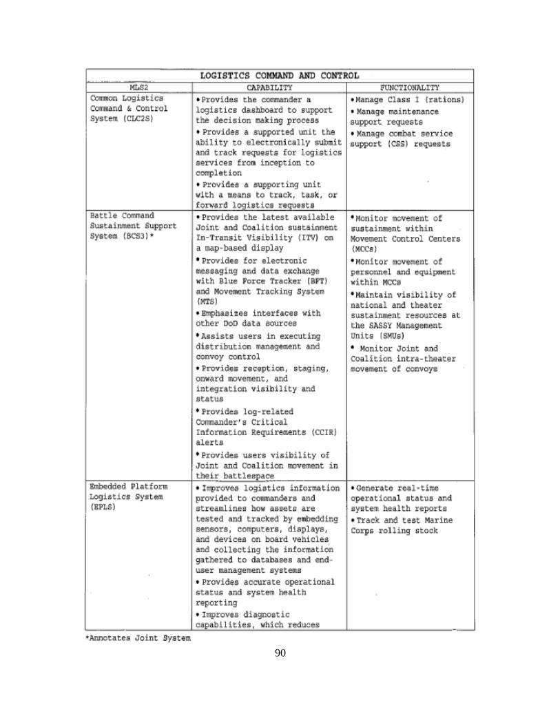
90
Oommon Logistics command & control System (CLC2S)
Battle command Sustainmant Support systorn (BCS3) •
LOGISTICS COMMAND AND CONTROL CAPABI LI TY FUNCTI ONALITY
• P~ovide~ the commander 3 logistics dashboard to support the dtcialon mAking procoes • Provides a supported unit the ability to electronie8l lY aUbmit and track requests for logistics services from inception to completion • Provic!ea A aupporting W1it wlth a meana to track. task . or forward }oqiatica request& • Provides th! lat!at ava!labl! Joint ~nd Coolition auatainment In-Tunsit Visibility (ITII) on a map-based display • Provides for electronic messaging and data exchange with Blue Porce Tracker (BPT) •nd Movement Trackin9 System (MTS)
• Emphasize& interfaces with other DoD data sources • A!Hli&U us!rst in ~x~eutlng dlctribution m~n~gtment 3nd convoy control • Provide• reception, ;t;(lging1
onward wovement, and integration visibility and otatuD 1 Provi~Scs; log- rchtcd commander's Critical rntormation Requirements (CClR) alert; 1 P.rovideo~ ua:et:'s visibi lity of Joint and Coalition movement in
• M$Mge Cl•$$ I (ntioni:) • Kcma.ge me int•na.nce support requests • Kanage combat service support cess) r~quecte
' Mon!tor moveMent of ;~;t~ in~nt within Movement Control Cent·er& {MCCs)
• Monitor mover.~ent of perf:onnel And equipment vithin MCCa ' Maintain vioibility of national and theater susta1~nt resources at tlle SASS¥ M&nagement lfnits (SMUS)
• Monitor Joint and coalition intra-theater ~ovemant ot convoya
their battlesp•£!.--,--~----,---r--~----------i f-::l!mb=o=d"d"'o"d-P"'l"•"t"f"o=rtll::---r~, '::Iro"~rov~ logiotico inform.:J.tion • Oonon.to rcal · timc Logistics System provided to commnnd@rs and operationQl status and (BPLS} streamlines how asseto are system health reports
tested and tracked by embedding • Track and teet Marine
•Annot~tee Joint system
sensors, comput&rs, displays, Corps rolling stock and devlc~~ on board vehicle& and colltct.1ng the intoz:m.&tlo·n s~thered to dnt~b~ses and ~nd· user management ayste•s • Provide.a accurate operat ional 1tatus and ayotem health reporting • Improves diagnostic capabilitle~ 1 wh1ch reduces
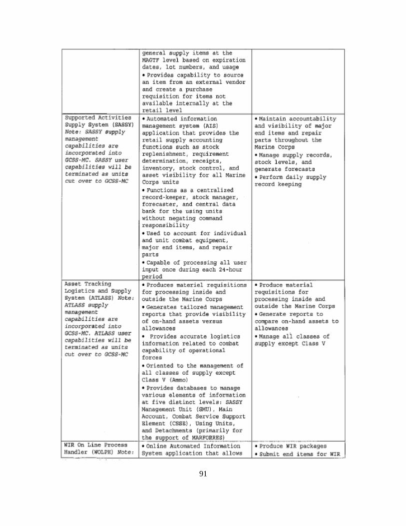
91
Supported Activities supply syetem (SASSY) Noto• SASSY oupply Rlil11cilge11'16nt capabilities aro lsJcorpor,st:.~d iTJt:Q GC$$•HC. SASSY uter c•pabilleies wl!J be eeratinaced as un1C:s cut over eo acss~HC
Asset Tracking LOgiotlco and Supply Syotem {ATLASS) Nbt~!
ATLASS 9upply mAnlgimtnt capab111t1es are incorporat..a' .into GCSS .. HC. ATLAS$ ussr capab1lit1es will be termin~ted '' unitQ cut ¢v~r to OCSS~MC
gener41 aupply items at the MAGTP level basGd on aXPiration dates, lot numbers, and usage • Providlia oapilbility to source an item trom an external vendor and crcotc ~ purchD~c requisition for items not av•i lable internally at the retail level • Automated inform~tion management eyateM (AIS) ~pplic~tion t hat provide~ the retail aupply accounting functions auch ~a stock replenishment, require.ent Cleteruunation, recetpt11, inventory, stock control, and a.aaet visibility for ill ~r:ine Corps unite • Functions as a centralized recorel·keeper, stock ~nager, f.OTec~Gt*r., nnd central oata ban_k for t he ua i.ng uni.ta without negating command reaponalbility • Used t o accoutl.t tor i l'td!vidu41 and unit c~t equipment, majo~ end itemg, and repai~ parts • Capo.ble of proceaaing all u.aer input once during each 24-hour
l~tod • ProduceG 11'1\ltedol requiaitiona for proceoeing inside and outside the Marine Corps • Generates tailored Nnagement report~ t hat provid• vicibility of on-ha_nQ. ilnete veuu.e allovanees • Provides accurate logiltiQ& Lntormation related to combat c~p~biLlty of o~r~tiort•l forcu • Oriented to the lfll,i)Mgcn~ent of all classes of aupply except Ch.$~ V {Atmo)
• Providet.: d.atabaau to runage various olements of i nformation at five dietinot l evelat SASSY M_,n~ge!M!nt lrnLt (St~U) , Mdn Account, Oombat service support Blement (CSSE), using unito, and ~tach~nt~ (primarily for
• M.aintain accountability and v l•lbility of major end items and repair part• throughout tho ~Urine corps • r4.i.n.age aupply c-eQordl, stock levels, and gtner~t• forecAoto • Pertorm daily gupply rocoJ:d kccpJ.ng
• P~:oduce !Uitoriill requisitions for processing inside and out•ide t he Marine Corp# • ~n.~rat.~ report!: to compare on-hilnd a1aet; to allo'wilancea • rof.a.n.age ali class&& of supply except Class V
}ho oupport of MARFORR,u,s,l _____ ·l-------.,------i 1-:-:w=,=.- o=n,.-:L"i"n"e--;;P:::r<>=ce"•"•"· - -+ , Online A\.ltomated I ntor..atlon • ProOuce WlR packages
Handler (WOLPH) Note • Systom application that allows • Submit end .Ltema to~ WI~ ..
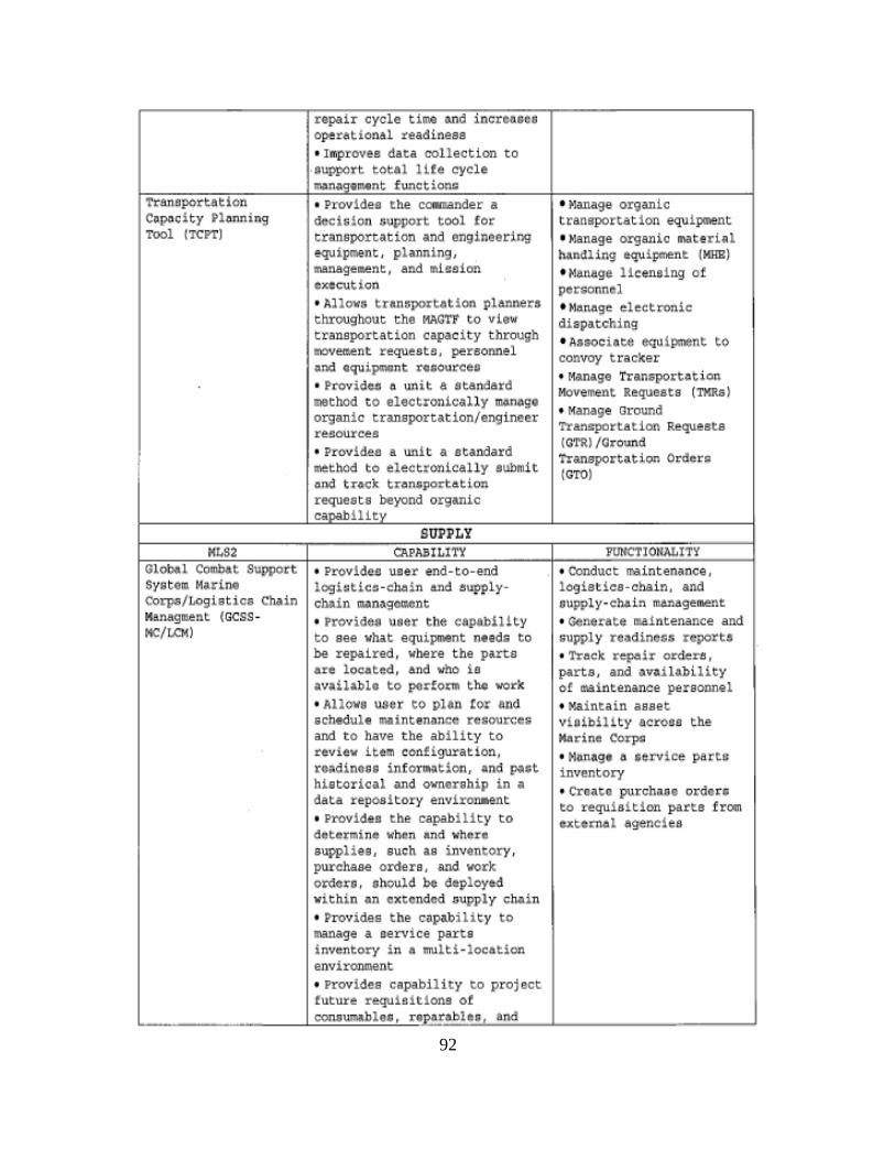
92
Trat~aport.ation
c~poeity ~lonnin9 Tool ['!'CPT)
Global Combat Support Syst tam. l~arine
corps/Logistics Chain M!nagm.ent (GCSS•
MC/LCM)
repair cycle timo ~nd increaneo oper~tlonal readiness • l ffoproves data collection to OI>WOYt toto! ll!e cycle ~n4gt~nt f~netion=
• Provides t he cOIWUnder a dcGi&ion 3upport tool for transportation and engineering equ ipment, plannin9, management , and mi~~ion oxtcution • Allowu tnnr;port•tion planner• throughout the lf{AG'l'lt to view transportation capacity throuih movement request&, personnel ~nd ~qu Lpment r~;o~rce1
• ProvidoiJ a unit a atandard method to electronically ~n~ge o~anic transportation/engineer resource& 1 ProvideD a unit a standard method to electronically aubmit and track tr4n&portation requests beyond orgcmic copob!Uty
SUPPLY CAPABILlTY
• Provides user end-to-end loghtie~ -elwlin and &upplyehain m4nage~nt • Providea uaer t he capability to see vhat equLpnent naed; to be repaired, where the parts are locat4d, and ~ !e ;;vdhblc to ptdoxm the wor-k • Allowa uoer to plan lor end sch•dul• ~inten~nce ~esource& and to have the ability to review item eort!ig~ratlon, r•adLness infor~tion, and ~'t historical ~nd O'lfMr·sh i.p in ~ dAta repository en'Vironaent • Provides t he capabl U ty to determine when and where supplies, such as i nventory, purchase orders, and vork orders , should bo deployed wi thin an extended ~upply chain • Provides t he Cilpabil i t.y to manage & aervice parts i nventory i n a multi -location environment
• Manage organic transportat ion equipment • t~lanage organic INltlrhL hAndling equi proont (KRB) • Manage Hc.nslng of personnel • Manage electronic dispatching • AGSOCi~te ~u1pment tO convoy tracker • ManAge 'tran;-port"tion Movement Requests (TMRs) • Manage Ground Tranaportatlon Request s (QTR)/Qround Transport~tion Order& (GTO)
PUNCTlONALITY
• OOnduct maintenance, logistics-chain , and uu~ply-ehaln management • Generate m.a.intenance and supply read1neGs reports • Trtu;k. re~ir ordere: , parts, and • vdh.bi.lity ol maintenance personnel 1 Mai ntain asset vioibility acroee the Morino Corpli • Mlln&ge a urv1ee parts inventory • croa.to purchMa ordou ~o requ!ait!on parts f rom extern~l ag~nc!ea
1 Provides capability t o project tuture requis itions ot oon&wrn.ble;, reoor~blOi 1 and '--·--------~~~~~=~"'----'--------'
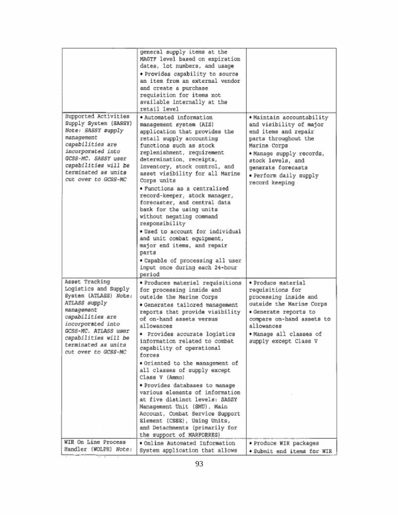
93
supported Activit i es supply system (SASSY) Note' SASSY Qupply mo~nage11'16nt
capabilities an lm:orporat:~d into <ICS$•/>IC, SASSY utor o~pobllit1 .. w11l bo r:eminar:ed as unlt:~ cut over r:o GCSS-MC
Asset Tracking LOgiotlco and supply Syotem (ATLASS) Mot•' ATLASS 9upply mnnagemant capab.tl!tlea are .inf;orpOr:-dt¢d .into c;css .. HC. ATLAS$ user oapnb1lities lt'ill b~ terminated as unit'G cut over to OCSS•HC
generAl aupply items at the MAGTP level basad o n expiration dates, lot numbers, and uea5Je • Provides capability to source an H~m trom an ext ernal v~ndor ond create A purchAac r equisi t ion for items not available internally at tho retail level • Automated inform~.tion manageme.nt eyatetn (1-.IS) application that provide• the retail aupply ocoounting functions such as stock replenishmen~. ~irewent
c:tete-r•n.tnation, rec.eipto, inventory, stock control, and aaaet visibi lity for ~11 M•rine Corps unite • Functions a& a centralized re-cord-k~epe-r, n~ock ~nager,
eorecaoter, and central data b;,nk tor t,he \l& i ng tmi t& without negating co~nd resporte!..biHt:y • Us~4 t o aeeoun.t: tor i lldiv!dual and unit cOOibat eq\llpo>ent, ~jor, end itemij1 and rop•ir part& • Ciil.p~le of proc::es sing all uaer input once during each 24·hour
1 period a Prod·ucoG tnl\teriel nquisitions for proceaeing inside and out8ide the Marine corps • Generates tailored management report' ~hat provide vicib!ltty of on•tumd Msets venw; allov&ne~s
• Provides accurate locaisties information reLated to combat CApab~lity of optr•tionAl forces • Oriented to t-he t~~rMnilgctaCnt of all c laggea of supply except CLa•• V (Ami!<>)
• Providec databaJ:Ie a to rr.anage various elements ot i nformation at five dietinct levela : SASSY M•nogeocnt Vnlt (SMU). Moln Account, cono.bat Service Support Blement (CSSB) , using unit o, and Detachment& (prim.rily for
• r.ti;intain aee<>untability arul vi sibility of major end He1ne and repair patti throughout the Marine corps • Manage supply "~cord&, stock levels, and generate foreeaete • Pertorm daJly supply record keeping
a Pr:oduco ~U.atedo:~l requisitions for proceasing inside and outuidc the Marine Corp~ • Generate reports: to compare on~~nd asaet# to Allowances • Ma.nage ali classes of supp Ly except Class v
!-;:;,;;;-=.,.-,====~-t-'ho ouppo<t of MAJU!O,R."R"'BS=,l'--cc--··r :-:-----·------1 WIR On Line ~roc:CJ;:.; • online A\Jtomated I ntorMtion • Prod:uce WIR packages Handl er (WOLPU) Note: System ~pplication that allows • Submit end i tom.a for: WIR
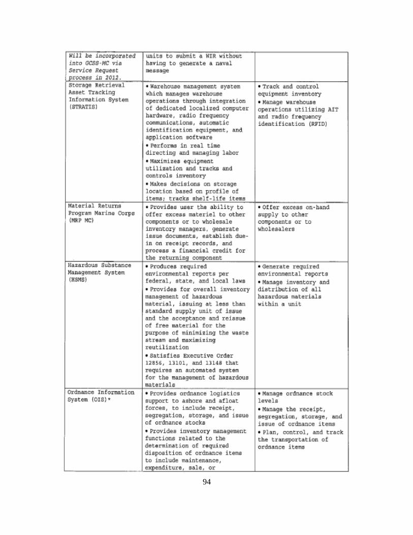
94
lt'l.ll b~t 1ncorpor4t<td into OCSS •MC vjn service Request
jprocess Jn 20J2 . storAge Retrieval Asset Tracking Information SYttem (9TRA'I'!S)
r.raterial Retum..g Progrom Marina Oorpo (MRP MC)
Uuard0\1.5 Sub!Jtance Management syete~
(HSIIS)
Ordnance Information System (OIB)•
unit:; to .s:ubmit a WIR 11.•ithout having to generate a naval fllellage
• Warehouse mi.nagement system which manage~ warehouse operations through integration of dedicated localized computer hardware, radio trequency commun1cat1one, automatic identi fication equipmant , and •pplic•tion aoftware • ~rforma in real time directing and managing labor • Maximizes equipment util12at1on and tracko and controls invontory • Make• deciaiona on storage loc~tion baaed on profile of items· tracks shelf-life iteme • Provides ueer the ~biHt:y to offer excess materiel to other components or to wholesale inventory managers, generate issue doeum~tg , ~at&blich duein on receipt recorda , and procea& ' finRnci1l credit for the return i ng component
• ProcSuceG rcqu 1 ted environmental reports par federal . state, and local lawa • Providea for overall inventory management of hazardous matert~l. L''uing ~t le=• th$n standa~ supply unit of lssu~ and t he acceptance and reissue of tree ~ter!al tor the purpoae of ~Lnim!v.!ng the Wftote ;treom ond moxim~zing reutilhation • Satisfies 6Xecut ive order 1285&, 11101, and 13148 that requtte• an Aut~ted eyot•m for the ~nigaocsnt of h•zardous t"W.teriale • ~vidca ordno~ncc logbti ca; support to ashore and afloat forces, to include receipt, teg•eg~tion, etortgo, •nd iaquo of ordnance stocks • Provides inventory management functions related to the determi n~tion of r•quired diapoaition of ordnance i tema to i nclude maintenance, CXDOndituro ealG, or
• Track and control equipment i nventory • Manage watehouee operations utilizing ArT •nd rQdio frequency !dent!f!cat!on (RFtO)
• OUer cxcc::w on -Mnd supply to other components or to wholea.alecs
• Gcncnte r~1 lred environmental reports • M;).Mge inventory and distribution of all hazardous materials withi n o un it
• Monllga ordrnmc• stock levels • Manage the receipt, ~egregation, ~torage, and issue of ordnance i tems • Pliln, concrol, and track the tran&pertation of o.rdn01nec item:;
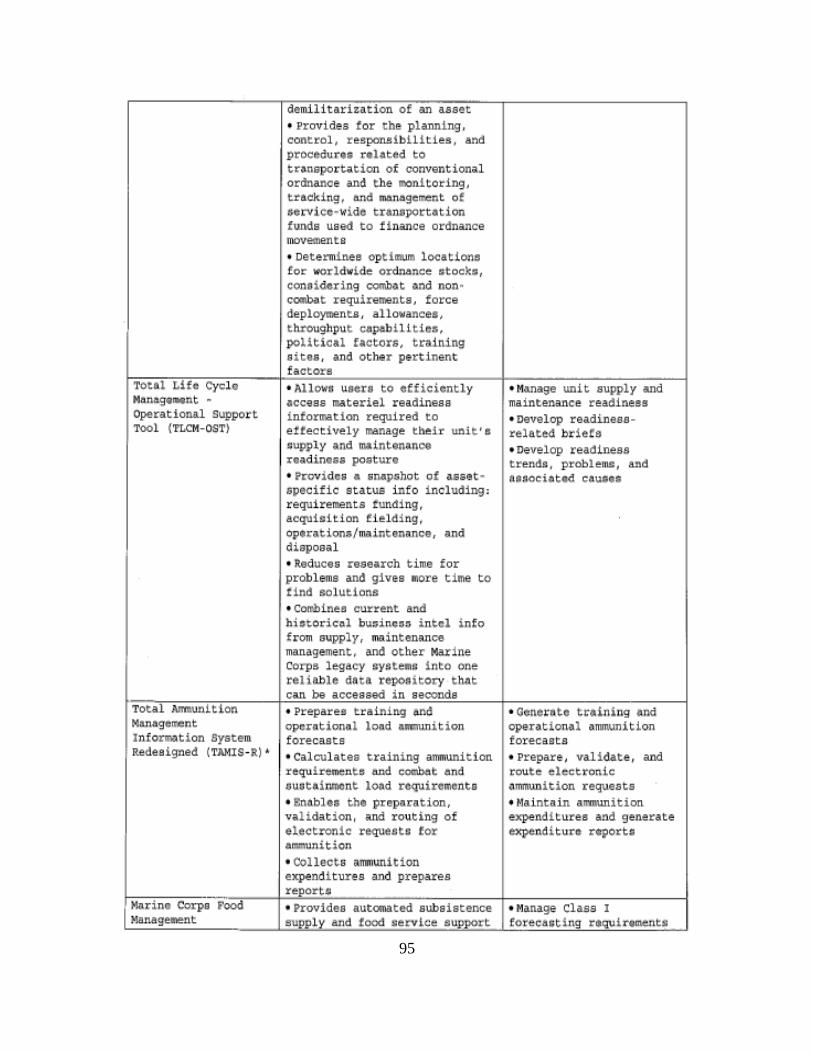
95
Total Life Cyclo Manage•nt " Operational Support T<>Ol {TLC!<-OSTI
Total ~vnition Nanagell'.ent Jnfor~tion SystQm Redeoigned {TAMIS-R) '
Marine Corps Food Manage~nent
demilitarization ot an asset • Provides tor the planning , control , r!&ponsi b111t1es, and procedu~•• reloted to tr~nspottation of conventional ordnance a.nd. t he lt'IOn! tor ing, t racking, and ~nagement of ~orvico·widc tranuportotion funds used to U nance ordnance movements • Determines optilftUil'l looationa for wo.rldwide ordnance stocka, considering combat ~nd non • c~t requirements, force deployments , allo~ances, throughput c~pabilities.
poLitical f~ctors, t raining s ites, and other pertinent fact ore • Allows user& to efficiently access materiel readiness information required to ettectively manage thei~ unit ' a cupply and mainton~nco roadintae posture • Provides • snopshot of assetspeci fic atatu& info including: requirements funding, acquicition f ielding, opt(ationa/maintenance, and disposal • Reduces ce&e«rch time for problems and 9ives more time to tind solutions • Co~rbinee eurrent and historicol buoincao i ntel info from supply, maintenance management, and other Ma,rine Corpa l egacy eyfltemu into one reliable data revooitory t hAt can be acces&9d i n seconds • Prepare• training and opcrotionol load ~itiQn fore-casts • Calculates training ammunit ion requi~ment!l and e~t and ouotai nmant lOAd rcQUircmcnto • Enables tht propnn.tion, v~lidation, •nd routing of electronic request~ for ammunition • Collects a.m1unition expendi tures and prepares report.c; • Provides autOl'flalted subs istence sup,Ply and tood serv1ce support
•Manage unit supply and maint&nance readiness •Develop readiness · related. brie!a • Develop readiness trends. problems=, and BO~Oe loted C~U$0$
• Goner~to tr«ioing and oparQt1on41 4mmunition tore-casts • Prepare, validate-, and route eleetronio ~mmunition requeats • Maintain a.IOOlUDit ion expendi tures •nd generate expendlturo roporto
• Manage Class I to~eca=t 1~g r•qu1~tmentl
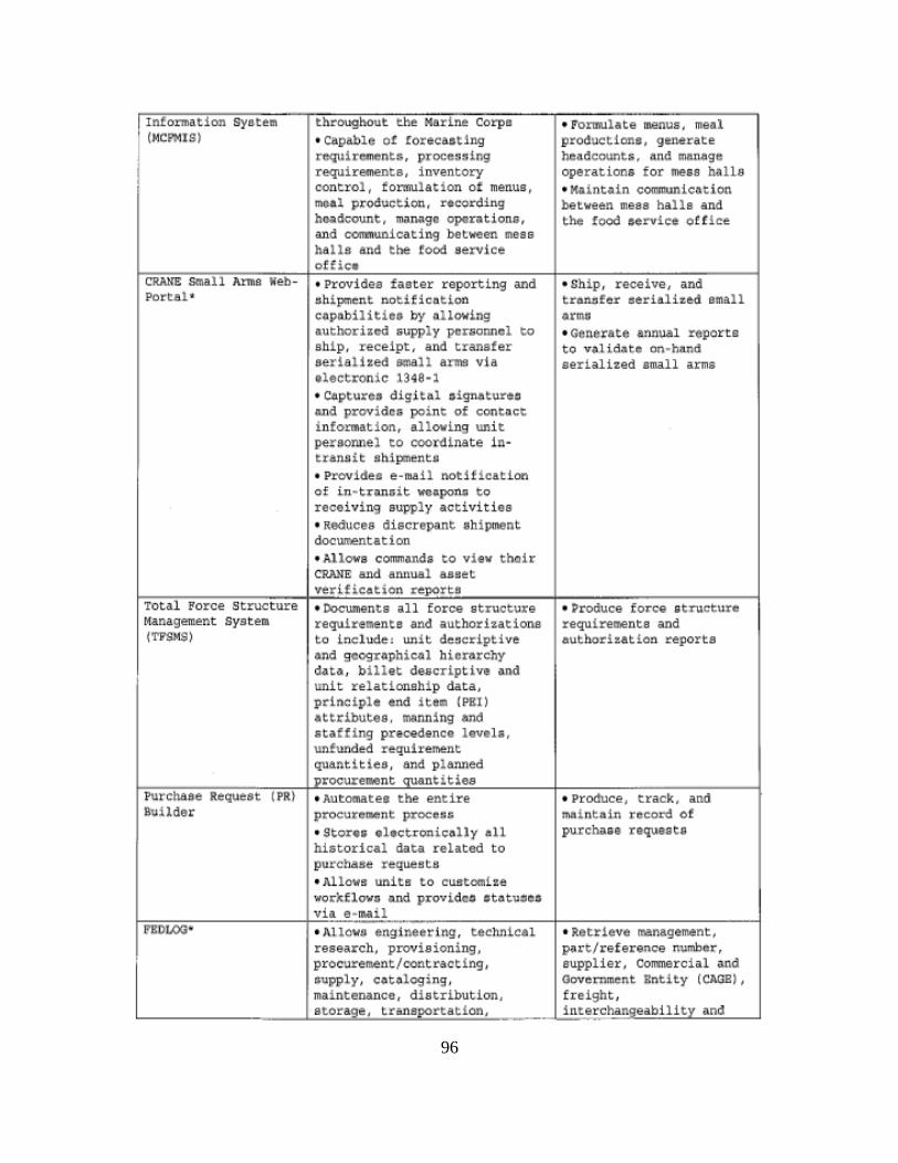
96
Intonnation System throughout tbe Harlne Corps • l"orii'IUlate 1nenus, meal (MC.,.IS) • capable o! corec:aating produc:tiont, generate
requirements, proceu~ing he3dcounts, and m&nege requi rements, inve.1tory operation• for mesa ha l ls control, formulation of m&nus. • Mdnt~in comm.unle~tion meal p:roduct ion, l"fCOrding between meaa halls and hoodcount, mon~go opor~tione, the food aerviee of f ice and communicating >et~en mees halls and t he foOd servtce offic•
CRANE small Anna Web- • Provides faster reporting and • Ship, receive, and Portal• shipmen t notifiefttlQ~ tran~ter e~rialized small
copllbilitioe by o.lLowi.ng 4rmu authorized suppl y ?Crsonncl to • Gener~te annual reports abLp, receipt, and transfer to validat• on•htl.nd serialized small a~s via serialized small arms electronic 1348-1 • Co.pturce:t d.igital !Signet.ur~~ and provide& point of ~ont~ct information, &llovlng unit pe.r·aonnel to coordlnate in-tranAit 6hipment~ • Provide& e-mail notification of in ~trQnoit weapon~ to receivin9 supply ao:tivities • Reduces discrapMJt ubi pnMJnt dcx:wnentation • Alleva eommanda to view thoir CRA.llE and an1tual a.uet ve-r ificat ion repor:£1
Total Porce Structure • Oocwnenta all force structuxe • SJroduce force structure Management system requirements snd a·.1thorizationa requirements and (TPSMSI to include ~ ""it ~oc~iptive authorization reports
ond googr~phicol hierarchy data, b i llet descrlptive and unit relationship data, pdl\etple 41\d item {PHI) att~ibutea. ~nn ing •nd staffing pre~denoe levels, unfunded requireme~t quantitieo . end plAnned
I procurement quant l;ies Purch.eee Requeat (PR) • Automates the: entire • Produce, track, and Build$r procurc~»oent proc;e:;i ma1nt~jn r.cco~ of
• Stor•r; ohct.ronicdly all purcbnaa raquaato historical data reLated to purehaee requests • ~\llows units to cuatocnlze wo~~flovu and provldco ot~tuoeo via e-mail
ROLOOW • ALlov.s engJneering, technic•l • Retrieve Nnagement, research, pvovisioling, P'rt/reference number, procurement/eontra~t!ng, supplier, Commercial And aupply1 cataloging, Government Bntity (CAGB) 1
maintenance, distrlbutlon, freight, s torage , transportiltion, interchangeabilitY and -
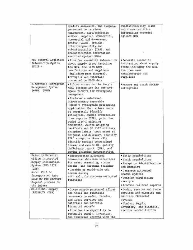
97
WEB Fed•rol LOgistics Intormation system (P~Ig) •
Kleetron!e Retrogyade Management system {eRr<S) (USN)
PrioritY Materi~l Office lntegrated supply I nformation Syote• (PMO 16181 (USN)
l'lote1 Wlll be 1ncorporot.d Jnto ocss .. Hc via St!rvice Requece process in the f utura Relational Supply (RSUPPLY) (USNI
qu,lity ~aourance, and diepos~l peraonnal to retriovc 1r.anagement 1 part/reference number. •upplicr, ~onmercial, Conue~cial and Govern1114nt Entity (CAGB), freight, interchangeabiltty and aubctltut~bilitY CI&S) . and ch•r~cterist ica inform.tion recorded acrainst NSNs • Provi(!u: essentia l intor&tion ~bout aupply item~ i ncluding the USN, the i t:ern name, manufacturo1 and suppliers (including port nun1l:leru), through a web i nterfa ce connected to FLIS dati • AUO'..r& OCCC&Si tO ·t he Navy' ti ATAC process and i t G hub·~d· apoke networ~ for retrogr•d• I!Ulnagement • Includes a web .. ba.sed DLR/SeconOnr.y Repar abLe (S!CRBPI retrograd~ proeo~cing
application thQt •llowu uuore eo accurately identify retrograde, aubmit tranaact!on it•m ~eport& (TIR) ~ print bor coded 1348· 1 shipping documents, create 5hipping manitest~ ft n(! DD 1387 zll i tary 3hipping lnbols, ·poet proot of shipment and dellve~ . id~ntify ATAC oxception Lt tms (SI) , identify carcaos constrained itemo; «nd cteQt~ EI , qua lity deficiency report {QDR) , and eooine ehiooina documentation • Incorporate!c autornatad comm•rcial dat~oc into~facco tor asset screening , status check•, o.nd 6hipm.ent t racking • capable or world-wide web aeee!:taibility with mul t iple cuot~r·orionted
functiono
• Oives supply personnel afloat t he toole and tunct iona "ecess~ry to ord!r~ reeeive, and ill'ue service& and materials and main~ain
t inrunciQl rocordc • Providu the ca.pohil i ty to ~econcile suppl y, i nventory,
subot!tutAbil!ty (I&S) ~nd char~ctcriot ico i nformation r•eorded against NSN
• Gen~rate essential information about aupply items including the NSN, the item name. ~nutact~~rs and ;uppl!ar$
• Manago and track SECRBP rctrogr~dc::;
• Bnt~r requieitions • Track re~iaitiona • Bxception. identifici.tion al\d h~rtdl i ng • Qenet At e autOI\!ted statu& update& • Confirm reqvi~; ition rec~ipta
• Produce tai lored report & • Order, receive and iiJsue services and material and maintai n f l nancial rGcord& • Conduct S-upply, inventory, and financial recorde re~onciliation
L---------~--------L!•~nd~t~l~n~o~n~c~la~l~re~c~o~r~da~~w~l~th~t=h~•~J-----------------------
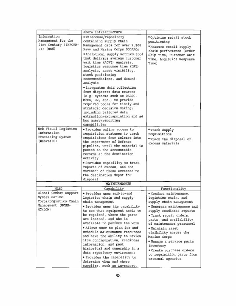
98
Intorcnat1on Ma.nagtrteJlt for t h e 21st Century (IN~iORM~
l l) fUSli)
Web ViAUa) LOgiatiCI Infor.,tion ~roceseing System f""bVLIPS)
f.ILS2 Global Combat Support SyCitam ~1arine
Corps/Logiatico Chain l>lanasement (OC$SMC/LOI)
shore i nfrastructure • worehouae/repoaitory containing Supply Chain Man1gement data for over 2,SOO Navy and Marine Corps OODAACo • Anolytical uupply metricr; tool that d~liv~rs average customer wait tin~ (ACWTI analysis, logiltico reoponae ti~ (LRT} on~ly•is, asset vitibillty, &took positioning reco~ndationa, and d~nd on&lyaia • Integrates data collection from di ;p~r~te data Bourcll (e.g. aystQms such as DAASC, MPC$1 02, etc .) to provLde r~quired toolo for t imely and ~tr~tcgic dcci;ion~~~ing; including tailor~ dot~ extraction/extrapolation and ad boo query/report ing c•P•b!Ht'!os • Provides online acctll to requisition #tatuaes to track requiaition. from rele&ae into the Department of Dlltnsa pipaline, unt il ~he material ia post~d to th~ accountable recordA at t he daati nation activity • Provide5 ca,pabil.ity to t.nc;:k reports of exceoo , ond the move~nt ot those excesses to th.e destination depot for dJ~p<>s:al
MAINTENANCE C6pel>111ty
• Providea user end-to-end logletlca -ohaln and •upplychain manageut.ent • Providu uCJer the capability to gee what equipment need¥ to be repaired, wh.ere ~he parte are lo~ated, and who is avoihbl• to petfonn t ho 'II'Ork • ALLowo \Iter to plan t or and echedule N inteMnce ~aourc11 and have the abil ity to revi~w Ltem configuration, rcodLnc55 informati on, and paGt historical and O\Fmerahlp in a data repoeitory e.nv1ronment • Provide.; t he capability to deter1nine when and whore eupplitiJ, ouch as invent~
• Optimize retail atoc>:. poBi t 1 oning • Meuure retail !lupply chain performn.nce (Order Ship Time, customer wait TiMe, LOgiotics Response Time)
• Tract aupply requi:dtt ons • Tt'tt.Ck tht: dhpo=d of CXCCi& mGt&IiAll
Functionality • Conduct mainten~ncc, logiaticbaChAin, And supply~clla1n 1nanagement • oenorate aaaint•nanoo anc1 ~u~ply readine$~ ~port$
• Tr~ck rapair order1, parts, and availability of maintenAnce personnel • Maintain oaset vioibility acroao t ho l.f.ar ine Corps • Manage a servic• parta inventory • Create purchaae ordere to requisit ion p~rts from ext~rnat agencieB
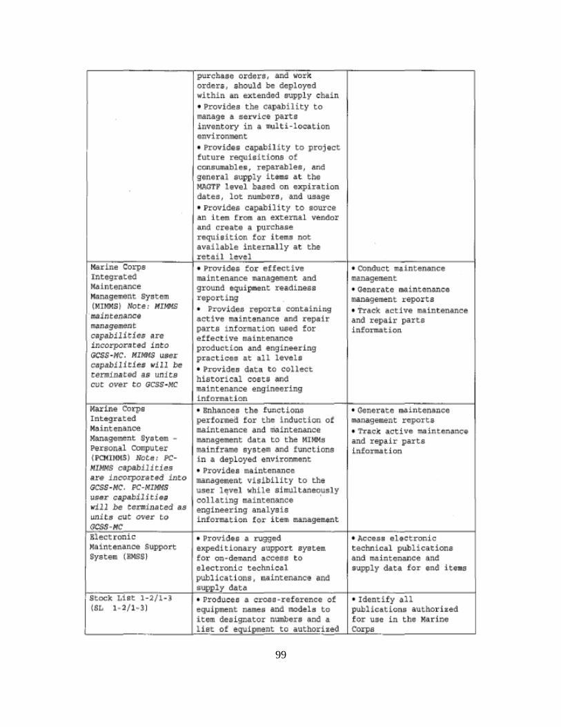
99
Marine Corps tntog:r-ote<l Maintenance Management b)ratem (MlMMSt Note J HIMMS ma1ntenance m.7mtgGme.nt: cupabil1t1c:; 11re incorpor~ttd into GCS$ -ftfC. MI MfdS Utst:r c•pobilitio• will be terminated a6 un1ts cue over to acss~MC
Kilrine Corp&
Integrated MCi i.ntcnance Management Syetem -~raonal computer ( PCMJMMS) 1'oto' PCH!HM$ c~bilities are inco.t'poraeed into GCSS -HC, PC-MIMMS uc•r CIP.bilitj•g will be ecrmlnQted as un1t!f cut over to GCSS·HC Electronic N8 ~ ntenanoe Support System (J!)1SS)
purche10 ordore, and work order•, •hould be d~ploycd within an extended eupply chain • Provides the ca,pabili.ty to manage 6 ~erviee parts invontory in a multi-location onvironment • Providtl capability to project future requisitions ot coneumftbleA, repara~lea, and gonoral #upply ltt~ At the MAOTF level bnaod on oxpiration dates, lot numbers, and usage • Provide& capability to source: an item from ~n externa! ven~or and create a purchaae requisition for itema not avail able internal l y a t the reta il Level • Provides tor oUect1vc maintenance management and ground equipm~nt readiness reporting • Provi<1C$ reL]Orts containing activo ~intenanco ~nd rep1ir parts i nformation used for effect ive maintenance production ~d engineering practicoo at all lavola • trovid.c:~ d.ftta to collect h1storic41 cost# and maintenance engineering !n.torution • Bnlumceo the functiono perto~ for the induction ot maintenance I Jlcl mintenance m,c~nageW~Cnt d_atn to the MIMMs mainframe system and functions in a deployed environment • Provides maintenance management visibility to the user l~vel vhLle simultaneo~sly collating maintenance engineering analysis in£or~tion for ite~ managem4nt
• Provides a ru9Sed expeditionary eupport ayotem tor on-dcw~nd accees to oloctronic technical publica t i ons, maintenance and 1upply data
• COnduct mainterusncc management • Oonerate maintcnlilnce management reports • Track active mainten•nce and repair parte infonnat.ion
• Oononto maintenance management reports • 1'raek active Nlnton!lnc~J and repi.ir parts information
• Access electronic technical publications and ~~lntcnance and a~ly data for end i toma
I Stock List 1-2/1-3 • Produces a croas-rsference ot • Identify all .. 3) equi pment ru:tlll.e~ and 111o0deh to pllbHcatlon~ authoriud
item deaignator numbers and a for use in tho Harino ________ _J~l~i~s~t~o!~e~qu~lfpmo~n~t~t2o~a~u~t~h~oEri~z~e~d~~Cor~~~ps------------------"
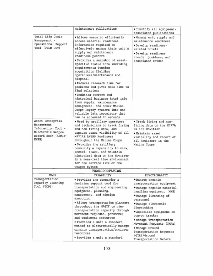
100
1 :~~:~.~~~= ~ycLO Operational Support Tool (TLC~I-OST)
i••••t Managem•nt Tnfo~Ption Tool • Blectronic ~~apon Reeord Dock {AKM[T· SWRB)
• Allowroo uscn to efficicntl y occeoo ~teri~ readineao i nformation required to etrectlvely .anagt thtir unit'G s upply ond ~a1ntenancc reAdiness posture • Provides a swpshot of o.ant .. epecltic etatus into !deludi ng requirement• tundlng acquisition fielding operations/maintenance and diaposal • Reduces reaearGh tiu for problelt~ an4 glves rnorec time to find oolution• • C~ine,; current ~md hietorical business intel info from supply, maintenance management, and other Marine Co~p~ lcg4cy ~y5temn i nto one
I ~i::l• data in ., that
• Used by arti llery opuator!l nnd ~ochnici«n& vo track firing ond non· tiring dnta, and capture asset visibility of all M?11A2 LW15S HowitterQ th~Qughout tho ~~rinc Oo~& • Provi<.1o& the ~ttilloxy GQmmUDity a caprubility to view, record, track, and maintain historical data on the nowltt.er !n a near-rtal time •nvironment for the aervice life of tho
• M~l'99: unit &1,1,pply <:~.nd maintenance re&dinese • Develop readiness · r.dat~ briels • Devel op readiness tr•nd#, p~Qblc~ . ~nd
nsuocintad ~auacs
• 'l'raek: firing end nonf iring d~t~ on the K777A LW 155 Howitzer • Maintain asset visi bility and record of all Rovitaero in t he Mtldr\0 OOrpa
~--~!..!X.!~ ~
Capacity P~~~ing Tool (TCPT)
~~LI~Tn7-----~~~ • Provides the conrmand~r a • Manage organic decioion ; upport tool for tron;po~totion •quipment transportation and engi neering • Manage orga_nic motorial equi[ldlent. phruting . h>ndl!ng equiponent (MHII managell'lent, an<l rn1G31on • Ktmnge HctJUfing of execution personnel • Atl0\'.'8 tr&n&port.ation ph.nne:te • Manage el@ctronic throughout t:be fo'I.AGTF to view ditpatching tranapo~tation capacity through • A~~ociat¢ equipment to movement requests , personnel convoy tr~cker and equipment resources • Manage Tranwportation • Provides a unit a standard MOVe.rnent Reque.ata (TMR8) method to electronically mAnago
I • Manage Ground orsanic transportation engineer 'l'nnsport.t'lltion Requests resources (GTR)/Vround • Providu a m'lit a otAndard
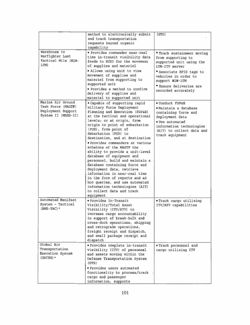
101
warehouse to wartighter Last Tael:teal M.U• (W2M· LTMI
Marine Air Ground T.sQk Foree (MAC'F'P) Deploym~nt support System II (XDSS-II)
Autom6ted Manifest syatom - Tactical (AMS-TAC)•
Ol<>Nl Air Transportation EXecution Syotom (GATES) '
method to clcct.ron lc~lly :;ubmit W'l'O) and track tranapor~ation requeste beyond o~an lc
COPoblllty • Provides commander near·real time in-transit vieibility d4ta feed~ to BCS3 for the movc~nt of suppl ies and materiel • Allows uaing unit to view IILOVell'lent of auppliec and mater iel !rom supporting to ;upporttd unit • Provicla• a method to confirm delivery of auppliea a.nd materiel to suPPorted unit • c.-pable o.f ou,pporting rapid militory Force Deployment Planning and Execution (PDP&£) at the tactical and operational ltvtl;i oT at origin, from origin to point of embarkation (POE), free point of debarkation (POD) to destination, and a~ de~tlnation
• Provi<leA cOill'AAnders at varioua ec;helon5 of the MAQ'H' the •bility to provide a uni t-level database of equipmont and peroonncl, build and maintain a dat•~oc cont~in!ng force and doployn4nt data, retriava ! nformetion in near-real time in tile rorm or reports and all hoc: queritl, &nd ulit automotea infortM~tion tecMologies (AITJ to col lect data and track •aul.,...nt • PrQVi dcs Ln·'l"ransit Visibility/Total Asset Viaibility (ITV/ATVI to incr•aGo corgo •ccount~bility in support of bre~k·bulk and croas-dock operations, shipping and retrograde operatio~s, freight receipt and dispatch, and emall packag~ receipt and dhoateh
• Provides complete in .. transit visibility (ITV) of personnel ~nd QGGCtG ~oving wit hin the Defense TransportatiOn System (DTS}
• Provides users automated funeti~~lity to proeec;/tr~ek co.rgo nnd passengor 1ntormat 1on, &Ul)ports
• Track eustain111ent llloving from supporting to supported unit using tba LTH· ITV server-• Aseoch.te RP'ID tags to vehicles in order to support W-'N ~ Jli11 • Bnaure deliveriea are recorded accurately
• COnduct P'DP&.B • Maint1in a ~taHse containing force and deployrMnt data • use automated information technologies !AITI to collect ~•ta a.M track equipment
•Track ca,~o utili2ing ITV/ATV capabil ities
•Track personnel and cargo utilizing ITV

102
mlUlagecncnt of reconeea, provide~ logl~t!cal $upport infomotion, gcn.,nttl atcmda.rd and ad hoc rt:ports, supports scheduling and foreca•ting, and provid.te mtssage routing and dellvery service for virtually all tranauort•tion data
C~rgo Movemant • Prov!den a~,~tQmllted $\lpport to • P'ro<::esQ Contlnent3.l Operation System t he traffic ll'I!Utl\g enent process United S~ttu (CONUS And (CHO!I). of receivi ng , packing, Outside Oontlnental
coneolidating, mode oeleotion, unHed Stat&e (OCONUS) marking, and docu~nting C!&rgo utovementc shiPQlGnts . • Jleportu in-traneit vlaibility i nformat ion for car9o and paasengers moving !h~ough the Del~n~e Tran$pOrta~Lon Syctem by p~viding dQt• ;o the Integrated Data Environment/Global T~aneportatLon Notvork Conve:rGence (ICC) .
Integrated Data • Provides visibility over • ~nerate line-item-level environment movement of pen~onncl o.nd data on assets to achieve <TOR) /Oiobol oquipmont aooote to wnr ITV/ TAV 'l'ra.nopor tat ioo pl~nners or combatant Network (GTN) commandsra and is •n aaaential ConvergenCle (IOC) • t ool !or support or deployed or
deploying forcea • P-rovide~ 1 i nc- item-level dAtn on a&set& to achie·te ITV/TAV
l1e.t ional ln·Tr(t.nsit • Uges RFID tag t echnology to • Trace the !dent!y, Vldbllty (ITVI pinpoint materi•L LocationA atatu•, and location of Server• whon tho matGri~l paeaGG cargo from origin to
through a checkpoint desti nation • Provides TAV of e:aterlel • Rec•i ve near real · tifne
poeitLon reports for cargo conveyance•
Portable Deployment • Provides & complete portable • Collect and proceau data Kit tPOK) RFlD solution !or real-time trom acti ve RPID tags on
nodal, tnd- to-•nd ·,i&ibility of materie L and tran$111.Lt ttte materiel and criti~al a!I!U data th~gh t he network moving through the supply chain to the DOD lTV network
earver sin~le Mobility
. • Allows user·s to track air, • Tr~ck t he crove!llent of
syotem (St<S) sea, an~ l and tran~portation cargo and personnel from tttltlets port of embarkation (P08) • Provides aggreg.ot.d rtporting to port of debarkation o f cargo, personnel and {POD) trantsportlltion a u et• • Provides rnls:s:ion detail tor tr;nsportQtion aset tl • Provide;; the ability to 5&11.rc:h for tranaportation aaeete by nodaL Loc:atJon -
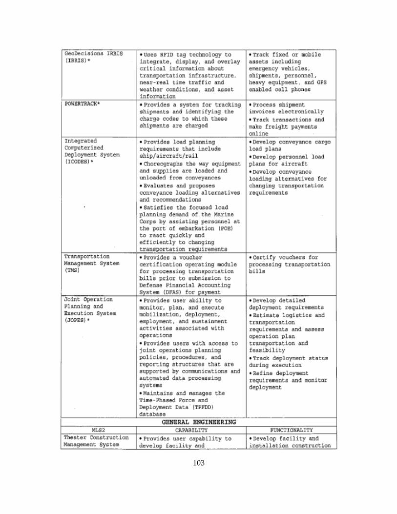
103
oeoOe.chiono lRRIS • uses RPID tag technology to • Track fixed or mobile (lRRIS) ' i ntegrate, dUplay. &_nel overlay aooets 1nclud l ng
crit1e~l 1n for~tion eaboue emergency veh1cleG , transportation infrastructure. ahipaenta, personnel , near-r~al time traffic and heavy equ Lpment, and CPS veathor conditione, Gnd agqgt gnablod coll phonoo informil!tion
POWERTRIICK' • Provi~es a sysMm tor tracking • Proc:e!Jt shipment uhi~entA and identi fying the i nvoieea etectronically charge codes to which these • Trea~;k. t.reanooc:t i ono end shipments are charged make freight pav-ants
online Integrated • f>rov:ide• lond pbnnlng • Develop eonvey•nce cargo computerized requirea~Gnts that include lo:.d plane Deployment System ship/aircraft/rail • Develop per1onnol load (I COORS) • • C~oreographe the way equipment plans for aircraf~
and auppliea •~ loaded and • oovolop conveyance unl04ded f~ conveyAncer. 1os41ng alternatives for • !valuates and proposes clumg i ng Lranaportat!on convey~e la.ding olternotives nquinMnta and recommendations • Satisfies the foouted lo&d plannlng demand of t ke Marine Corpa by eucieting peraonnel at the port of emb1rkation (POBI to react quickly ond et'ticlently to changing tran!~Ortation requirements
Transportation • .Providoo R voucber •Certify vouohera for Management syat~ certification operating ~ule processing ~ranaportntion (TMS) for prooeesing transportat ion bills
bills prior to submiedon to Defense Pinanci~l Accounting System. (DFAS) for oaYI:lent
Joint Operation • ProvideD u$er abillty to • Develop detailed Planning ~nd monitor. plan. and execute deploym•nt rtquirementa Execution Syatee mobilization, deployment, • Bstima.t• togirotics and (JOP&:S) • employment, and sustainment tunaportation
activltieG •n$ocjated w1th requirements and •sees& optrationQ operation plaft • Ptovides uaan witb occeu to trAneportotion ond joint. operations plaMing feasibility polioleQ , procedutes, BM • Traok deployment status reporting a t rueturea that are during ~x~cut!on supported by communications and • Refine deployment aut~mated data processing roquiremento and monitor nyctent.lil deployment • Moin~in; ond ROnog•5 the Tim@· Phased Force an~ Oeploy!Mnt Data ' (TPPODJ dt'lt~b~ct --· GENERAL BNGJNSBRJNG
MLS2 CAPABI~lTY FUNCTIC»>M.lTY Theater Com;truot ion • Providea uaer capAbility to • Develop facility 1111d Management Syt~ttm dcvcl~ focillty ood in~t4llat!ort construction
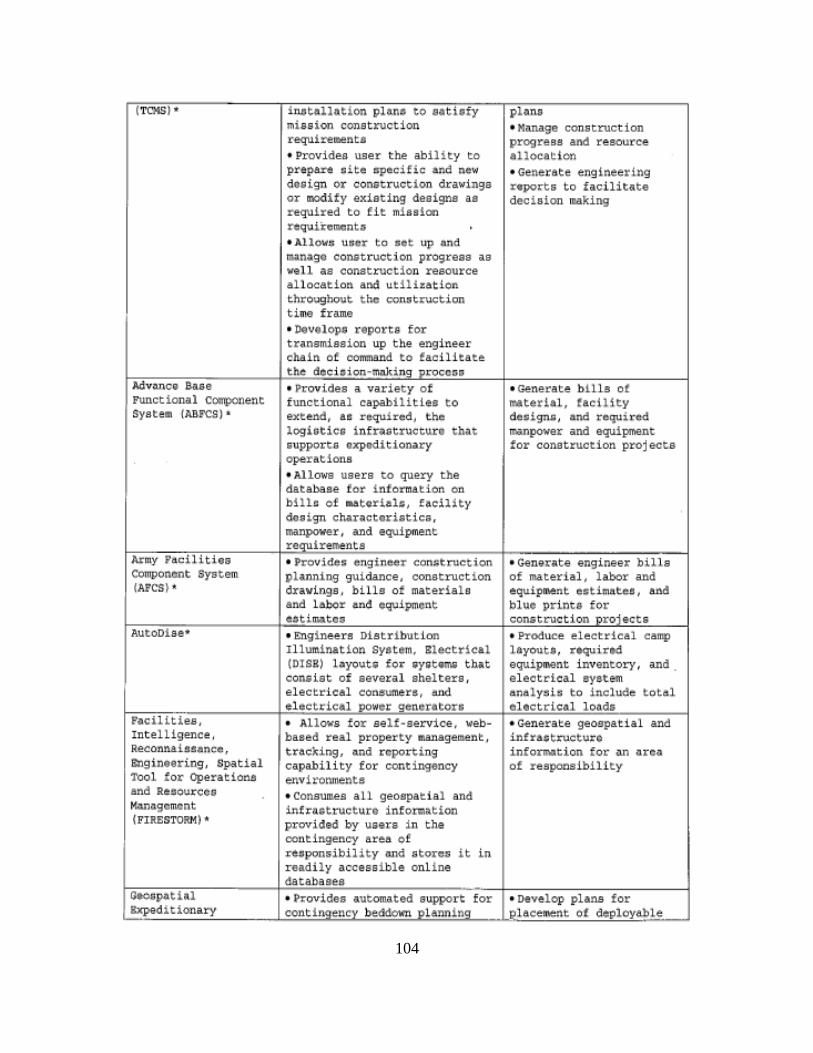
104
(TCHS]• inotallation pl~no to eotiefy phns mission construction • Nnnago construction requireeenta progres~ and resource • Provides user the ability to •llocatton pr•pare aitc ~pecific and new • Ge.neraee engineeri.ng dooign or construction drawings nport& to facilit.ate or modify existing designs as decioion m.aiUng required to tit mission reQUik-omonta • Allovt: U!ler tQ set up 3nd ~n~go conatructioo progreas as well as oonstruotion resource allocation and utiliz&tio~ throughout t ho oon3truction time frame • Develope reports for transmission up the engineer chain of command to facilitate the decision-makin~ u~oecGo
AdvQnce Ba.se • Provides a variety of • G&nerate billa ot Functional component functional capabilities to lt'illterial, taetUty Systell'l fABF<$) • ext.end, ae required, tho design~, •nd required
logioticG infr;structuro that manpower and equipment &upporta expaditionary tor construction projects operations • Allows users to query the database for infornAtion. on bHle of aatoriab, hc1lity do;~gn ch4rAotGriatica, manpover , and equipment requirements
Army Pac:ilit.iea • Provid:t:-t; f.!nglnMT eonnruetion • Cene~ate engineer bills Component System pli.Jlning guidance, construction of material, l ilbor and (APCS)' dr&vinga, bil ls of materials equipment ~stimates, aod
and l&bor •nd equipment blue prints for eatimateo conatruction oroiectt
AutoDiee>• • Engineers Distribution • Produce electrical camp Illumination Syet~~. Eltctrical layout.t, rtquirtd (DISR) l~yout& fo~ ~y&t4~ th~t. equipMnt inventory, and . coneist of aavoral aholters , e lectrical eyet@m elect.r-le.tl eonsumf!,ra, and analy!Sl:.: to i-nclude total tltct.rical powor ganorotorG electrical loada
Facilities, • Allows tor self-service, web- • Generate geospatial and Intelligence, baaed real property management, infraotz:ucturG Reconna i~sa•nce, tr~e~ing, ~nd reporting infor~tion tor ~n llrea engineering, Spatial capability for contingency of responaibility Tool for Operationb e.nvi ronmente: and R.eeoureeo • consum.ea all geoapatial and M.::mo.gamont infrQ~tructure int~rmation (FIRESTORM) • provided by u&ar& in t he
oontingeney area or ~~oponsibil ity ttnd store$ it in r eadily accessible online databases
Oe<>6potial • Provides autolll4tl"d oupport for • Develop plans for Jxpedltionary contingency bedd.ow:1 PlanninQ I ohce,.nt of d•ployal>ie
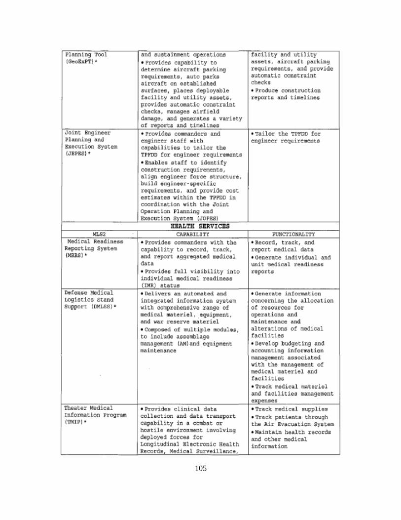
105
7001 l•nd -·· I facility ond utility (~¢!x.PT) • • Provides capability to b.S$Ctfl, tlirc.rttft pa.r k S.ng
determine aircraft parking roquirelflontu, md provide roquirements, auto parks automatic constraint aircraft on eetibl iahtd chec.ka surfaces, plac~e deployable • Produce conetruction faciliey and utility •&sets, rcportA and timelin~ provides automatic constraint checks, manages airfield damage, and generate• a variety of ~nd tim~linlilli
-Jomt • Provides cormnandera a.nd • Tailor the TPPDD for PlAnning •nd enginee~ ataff with eng!neer re~iremeota Bxccution system cap~ilitlo» to tailor the (JBPESJ• TPPDD tor engineer requirements
• lru~.bloB ota.ff to idontify construction requirements, align engineer force etructur•, build enginttr·cptcilic requirements, and provide cost esti~tee within the TPPDD in coordination wi th the Joint
I ~ra~~on !~anni~
!.!i:Q2 -:-• ProvidcG co!MIMdcrs vith the • Record, track, ond
R~portin,g Syst~m c-apability to record , track, report medical data (KRRS) • and report Aggregated medical • Generate i ndlvidual and
d3tl' unit medical readine1~ • PrOvideo ful l vioibility into report• ~~:!;idual medical readiness
D.tfen$e • Deliver:; ~m automated and • Genente i nfot1110tion r..ogiltics St-a.nd int•g,ated information system conce rning the allocation Support (D>ILSS) • v1tb comprehensive range ol ot' resources !or
~~~edical materiel, .•quipmont, operation• and And w~~ rcncrvc m~tericl mainton~ncc ~nd
• OOnlpo&ed of mul tiple IIICid\1118, alverations or medical to includo aasemblage racilitl .. min•gement (AM) illld equipment • Develop budgeting ~d ~raintenance. accounting information
man~gcmcnt ~aaoci~tcd with the management of medical materiel and focil itiQ.6 • •h ·ack mcxU.cal m~todol ond fAoilitioa manngemont
• Provides ·,.1 d•t• • Track M.,,,; ••' aupplioo Intormation "Progr.er~ collection and data tran=port • Tr~ck p~tient5 through ('IT41P) • capobility in o comb4t or the Air Evacuation Syatem
hostile environment involving • Maintain health recorda deployed torces fot and othe~ medic~l Longitudinal llect~onic Realth information
M• •• ol
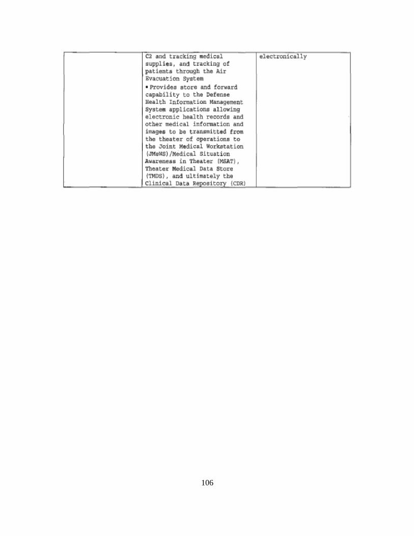
106
107
LIST OF REFERENCES
Anderson, R. L. (2012, May 15). Marine Corps Private Computing Environment
Strategy. Retrieved from
http://www.hqmc.marines.mil/Portals/156/Newsfeeds/SV%20Documents/Marine
_Corps_Private_Cloud_Computing_Environment_Strategy_15_May_2012.pdf
Arno, C. (2011, April 14). The advantages of using cloud computing, cloud computing
can be very quick and easy to get up and running. Cloud Computing Journal.
Retrieved September 18, 2011, from http://cloudComputing
.sys-con.com/node/1792026
Barreto, A., (2011, December). Integration of virtual machine technologies into hastily
formed networks in support of humanitarian relief and disaster recovery missions
(Master’s thesis, Naval Postgraduate School). Retrieved from
http://www.hsdl.org/?view&did=699514
Bittman, G., Weiss, G. J., Margevicius, & M. A. Dawson, P. (2012, June). Magic
quadrant for x86 server virtualization infrastructure. Retrieved from
http://www.gartner.com/technology/reprints.do?id=1–
1B2IRYF&ct=120626&st=sg
Brogan, M. M., (2010). Equipping the nation’s expeditionary force of choice Strategic
Plan 2010–2014 Marine Corps Systems Command. Retrieved from
http://www.marcorsyscom.marines.mil/AboutUs.aspx
Buyya, R., Yeo, C. S., Venugopal, S., Broberg, J., & Brandic, I. (2009). Cloud
computing and emerging IT platforms: vision, hype, and reality for delivering
computing as the 5th utility. Future Generation Computer Systems, 25(6), 4.
Retrieved from www.cloudbus.org/reports/CloudITPlatforms2008.pdf
Chief Acquisition Officers Council. (2012, February). Creating effective cloud
computing contracts for the federal government, best practices for acquiring IT as
a service. A Joint Publication of the Chief Acquisition Officers Council.
Retrieved from https://cio.gov/wp-content
/uploads/downloads/2012/09/cloudbestpractices.pdf
Corrin, A. (2011, April). DoD not ready for total cloud migration, CIO says. FCW The
Business of Federal Technology. Retrieved from
http://few.com/articles/2011/04/21dod-cio-takai-acquisition-reform-cloud.aspx
108
Costlow, T. (2012, April). Compact military VSATs have big impact. Defense Systems
Knowledge Technologies and Net-Enabled Warfare. Retrieved from
http://defensesystems.com/articles/2012/03/28/c4isr-2-military-vsat-technology-
advances.aspx
Crnkovic, D. (2010). Constructive research and info-computational knowledge
generation. In Model-Based Reasoning in Science and Technology. Berlin,
Germany: Springer
Denning, P. J. (2006, April). The profession of IT, hastily formed networks.
Communications of the ACM,49(4), 15–20.
Department of Defense. (2005, May). Assistant Secretary of Defense for networks and
information integration/DoD Chief Information Officer (ASD(NII)/DoD CIO.
Department of Defense Directive Number 5144.1. Washington, DC: Author.
The DoD Deputy Chief Information Officer. (2011). The DoDAF architecture framework
version 2.02. Washington, DC: Department of Defense.
Donovan, F., & Katzman, J. (2010, May). Head in the clouds: DoD turns to cloud
computing. Defense Industry Daily. Retrieved from
http://www.defenseindustrydaily.com/defense-cloud-Computing-06387/
Dunford, J. F. (2012, May 15). MAGTF expeditionary logistics Initial Capabilities
Document (ICD). [MROC Decision Memorandum 40–2012]. Washington, D.C:
Author.
Epperly, J. M. (2007). Transformation for disaster relief: developing a hastily formed
network during operation vigilant relief. Washington, DC: National Defense
University, Center for Technology and National Security Policy. Retrieved from
http://www.dtic.mil/cgi-
bin/GetTRDoc?Location=U2&doc=GetTRDoc.pdf&AD=ADA463072
Geelan, J. (2008, November 3.). Six benefits of cloud computing. Cloud Computing
Journal. Retrieved from http://web2.sys-con.com/node/640237
Global Combat Support Systems-Marine Corps. (2013). Marine Corps System
Command MCB Quantico. Retrieved from
http://www.marcorsyscom.marines.mil/ProgramManagementOffices/GCSSMC.as
px
Griggs, A., & McVicker, M. (2011, August). Marine Corps tactical service oriented
architecture technology insertion approach. Washington, DC: Author
Hayes, B. (2008, July). Cloud computing. communications of the ACM, 51(7). Retrieved
from http://dl.acm.org/citation.cfm?id=1364786
109
HQMC C4. (2011, October). Marine Corps Enterprise Network (MCEN). Retrieved
from
http://www.hqmc.marines.mil/Portals/156/Newsfeeds/SV%20Documents/Marine
%20Corps%20Enterprise%20Network.pdf
HQMC I&L. (2013). Tactical service oriented architecture framework. Washington DC:
Author.
Hawkins, R. D. (2013). Defense Information Systems Agency strategic plan 2013 – 2018
Version 1. Retrieved from
www.disa.mil/About/~/media/Files/DISA/About/Strategic-Plan.pdf
iGov. (2011, February). iGov awarded $12 million contract modification from USMC
for TCWS. Retrieved from http://www.igov.com/news-and-events/138-igov-
awarded-12-million-contract-modification-from-usmc-for-tcws
iGov TCWS. (2011, April). Tactical Collaborative Work Suite 2.0 (TCWS) virtual
hosting platform System Design Document (SDD). Quantico, VA: Marine Corps
Systems Command (MARCORSYSCOM) Information Systems and
Infrastructure Product Group 10.
Joint Chiefs of Staff. (2010). Joint operations (publication 3–0 incorporating change 2).
Washington, DC. Author. Retrieved from
http://www.fas.org/irp/doddir/dod/jp3_0.pdf
Kubic, C. (2008). DoD cloud computing security challenges. Retrieved from
http://csrc.nist.gov/groups/SMA/ispab/documents/minutes/2008–12/cloud-
Computing-IA-challenges_ISPAB-Dec2008_C-Kubic.pdf
Kundra, V. (2010, December). 25 point implementation plan to reform federal
information technology management. Executive Office of the President
Washington DC/Office of Management and Budget Office of E-Government and
Information Technology. Retrieved from http://www.cio.gov/documents/25-
Point-Implementation-Plan-to-Reform-Federal%20IT.pdf
Kunkel, L. E. (2013). Maritime connectivity improved over 100% with ESEM upgrade to
1366 modem for $2000 per ship. Washington, DC: Author.
Lee, B., Grance, T., Patt-Corner, R., & Voas, J. (2012, May). Cloud computing synopsis
and recommendations. NIST Special Publication, 800(146). Retrieved from
http://www.nist.gov/manuscript-publication-search.cfm?pub_id=911075
Lehman, T. J., & Vajpayee, S. (2011, March). We’ve looked at clouds from both sides
now. SRII Global Conference (SRII), 2011 Anuual (pp. 342-348). IEEE.
Retrieved from http://ieeexplore.ieee.org/stamp/stamp
.jsp?tp=&arnumber=5958106
110
U.S. House of Representative Armed Services Committee Subcommittee on Terrorism.
(2009). (Statement of R. F. Lentz). Retrieved from
http://armedservices.house.gov/pdf/TUTC050509/Lentz_Testimony050509.pdf
Logical Decisions. (2013). Software, consulting and training for more effective
decisions. Retrieved from http://www.logicaldecisions.com/
Lowe, S. (2009). Mastering VMware vSphere 4. Indianapolis, IN: Wiley.
Marine Corps Installation and Logistics Roadmap. (2013). 2013 Marine Corps
installation and logistics roadmap. Retrieved from
http://www.iandl.marines.mil/Portals/85/Docs/Division%20LP%20Documents/M
CILR_lowres_June20-1.pdf
Marine Corps Information Environment Unification Campaign Plan. (2013, April).
Marine Corps information environment unification campaign plan FY 2013–
2014, a plan of actions to unify the MCEN (Draft v78). Washington, D.C.:
Headquarters Marine Corps Command, Control, Communications, and Computers
Department.
Marine Corps Warfighting Lab. (2013). Marine Corps Warfighting Lab (MCWL)
concept-based experimentation. Quantico, VA: Author
Marine Corps Systems Command. (2013). Marine Corps Systems Command MCB
Quantico. Retrieved from http://www.marcorsyscom.marines.mil/AboutUs.aspx
MARCORPSYSCOM Information Systems and Infrastructure Product Group 10. (2011,
November). Tactical Collaborative Work Suite (TCWS) 2.0 Virtual Hosting
Platform (VHP) System Administration Manual (SAM). Quantico, VA: Author.
Mell, P., & Grance, T. (2011). The NIST definition of cloud computing. NIST Special
Publication 800(145). Retrieved from www.nist.gov/itl/cloud/upload/cloud-def-
v15.pdf
Microsoft Server and Cloud Platform. (2013). Server virtualization. Retrieved from
http://www.microsoft.com/en-us/server-cloud/virtualization/default.aspx
Nelson, C. B., Stamberger, J. A., & Steckler, B. D. (2011, October). The evolution of
hastily formed networks for disaster response, technologies, case studies, and
future trends. Global Humanitarian Technology Conference (GHTC), 2011 IEEE
(pp. 467-475. IEEE. Retrieved from
http://www.cisco.com/web/about/doing_business/business_continuity
/Paper_124_MSW_USltr_format.pdf
Newlon, C. M., Patel, H., Pfaff, M., Vreede, G., & MacDorman K. (2009, May). Mega-
collaboration: the inspiration and development of an interface for large-scale
disaster response. 6th International Conference on Information Systems Crisis
111
Response and Management (pp. 10-13). Retrieved from
https://scholarworks.iupui.edu/bitstream/handle/1805/3210/Mega-
Collaboration_Newlon_et_al_2009_ISCRAM.pdf?sequence=1
Oken, W. (2012). The future of architecture collaborative information sharing DoDAF
version 2.03 updates information sharing for DoD enterprise architecture
conference. [6]. Retrieved from
http://www.dodenterprisearchitecture.org/program/Documents/OSD%20AI%20%
20Brief%20to%20DoD%20EA%20Conference,%2020120429Five%20Elements.
Olsen, D. (n.d.) MCEITS 101. Retrieved from http://www.mceits.usmc.mil/
Roulo, C. (2012, October). Official describes joint information environment. News
American Forces Press Service. Retrieved from
http://www.defense.gov/news/newsarticle.aspx?id=118092
SECNAVINST 5400.15C CH-1 ASN. (2011). Commander Marine Corps Systems
Command unique responsibilities enclosure 5. Retrieved from
http:acquisition.navy.mil/content/download/10195/.../5400.15c 20ch-1.pdf
Shen, Z., & Tong, Q. (2010). The security of cloud computing system enabled by trusted
computing technology. 2010 2nd International Conference on Signal Processing
Systems (ICSPS). Retrieved from
http://ieeexplore.ieee.org/stamp/stamp.jsp?tp=&arnumber=5555234
Smartronix. (2007). Tactical Collaborative Work Suite. Retrieved from
www.smartronix.com/Portals/0/pdf files/TCWSSlick.pdf
Takai, T. M. (2012, July). Cloud computing strategy. Washington, DC: Chief
Information Officer, Department of Defense. Retrieved from
http://dodcio.defense.gov/Portals/0/Documents/DoD%20Cloud%20Computing%2
0Strategy%20Final%20with%20Memo%20-%20July%205%202012.pdf
Tatham, P., & Kovacs, G. (2010). Developing and maintaining trust in post-disaster
hastily formed networks. Advanced Manufacturing and Sustainable Logistics (pp.
358-371). Springer Berlin Heidelberg. Retrieved from
http://link.springer.com/chapter/10.1007%2F978–3–642–12494–5_32#page-1
Troy, R. & Helmke, M. (2009). VMware cookbook. Sebastopol, CA: O’Reilly Media.
United States Government Accountability Office, Report to Congressional Requestor.
(2010, May). Information security, federal guidance needed to address control
issues with implementing cloud computing (GAO-10513). Washington, DC:
Author. Retrieved from http://www.gao.gov/assets/310/305000.pdf
112
Virtual Computer. (2013). Type-1 vs. type 2 client hypervisor. Retrieved from
http://www.virtualcomputer.com/type-1-vs-type-2-hypervisor
VMware. (2013). Infrastructure virtualization and management. Retrieved from
http://www.vmware.com/virtualization/
Walters, T. (2012, July 30). Tactical Collaboration Work Suite 2.0 receives authority to
operate and connect. Marine Corps Enterprise Services (MCES) II(3), para.1.
Retrieved from http://www.mceits.usmc.mil/
Xen Project. (2013). Xen project. Retrieved from http://www.xen.org
Zeng, Q., Wei, H., & Joshi, V. (2008, April). An efficient communication system for
disaster detection and coordination emergency evacuation. Wireless
Telecommunications Symposium, 2008. IEEE. Retrieved from
http://ieeexplore.ieee.org/stamp/stamp.jsp?tp=&arnumber=4547584
Zhang, S., Zhang, S., Chen, X., & Huo, X. (2010, January). Cloud computing research
and development trend. Future Networks, 2010. ICFN'10. Second International
Conference. IEEE. Retrieved from
http://ieeexplore.ieee.org/stamp/stamp.jsp?tp=&arnumber=5431874
113
INITIAL DISTRIBUTION LIST
1. Defense Technical Information Center
Ft. Belvoir, Virginia
2. Dudley Knox Library
Naval Postgraduate School
Monterey, California