Embed Size (px)
Citation preview
The 30th International Electric Propulsion Conference, Florence, Italy
September 17-20, 2007
1
NEXT Long-Duration Test after 11,570 h and 237 kg of Xenon Processed
IEPC-2007-033
Presented at the 30th International Electric Propulsion Conference, Florence, Italy September 17-20, 2007
Daniel A. Herman*
ASRC Aerospace Corporation, Cleveland, OH, 44135, U.S.A.
George C. Soulas† and Michael J. Patterson‡ NASA Glenn Research Center, Cleveland, OH, 44135, U.S.A.
Abstract: The NASA’s Evolutionary Xenon Thruster (NEXT) program is developing the next-generation ion propulsion system with significant enhancements beyond the state-of-the-art in ion propulsion to provide future NASA science missions with enhanced mission capabilities at a low total development cost. As part of a comprehensive thruster service life assessment utilizing both testing and analyses, a Long-Duration Test (LDT) was initiated to validate and qualify the NEXT propellant throughput capability to a qualification-level of 450 kg, 1.5 times the mission-derived throughput requirement of 300 kg. This wear test is being conducted with a modified, flight-representative NEXT engineering model ion thruster, designated EM3. As of September 1, 2007, the thruster has accumulated 11,570 hours of operation primarily at the thruster full-input-power of 6.9 kW with 3.52 A beam current and 1800 V beam power supply voltage. The thruster has processed 237 kg of xenon surpassing the NSTAR propellant throughput demonstrated during the extended life testing of the Deep Space 1 flight spare. The NEXT LDT has demonstrated a total impulse of 9.78x10⁶ N·s; the highest total impulse ever demonstrated by an ion thruster. Thruster performance tests are conducted periodically over the entire NEXT throttle table with input power ranging 0.5 – 6.9 kW. Thruster performance parameters including thrust, input power, specific impulse, and thruster efficiency have been nominal with little variation to date. Lifetime-limiting component erosion rates have been consistent with the NEXT service life assessment, which predicts the earliest failure sometime after 750 kg of xenon propellant throughput; well beyond the mission-derived lifetime requirement. The NEXT wear test data confirm that the erosion of the discharge keeper orifice, enlarging of nominal-current-density accelerator grid aperture cusps at full-power, and the decrease in cold grid-gap observed during NSTAR wear testing have been mitigated in the NEXT design. NEXT grid-gap data indicate a hot grid-gap at full-power that is 60% of the nominal cold grid-gap. This paper presents the status of the NEXT LDT to date with emphasis on comparison to the NSTAR extended life test results.
* Research Engineer, Propulsion and Propellants Branch, and [email protected]. † Electrical Engineer, Propulsion and Propellants Branch, and [email protected]. ‡ Electrical Engineer, Propulsion and Propellants Branch, and [email protected].
The 30th International Electric Propulsion Conference, Florence, Italy
September 17-20, 2007
2
Nomenclature d = axial distance, m dDome = accelerator grid dome height, m JB = beam current, A JNK = neutralizer keeper current, A JDC = discharge current, A J+ = singly-charged ion current, A J++ = doubly-charged ion current, A L = non-dimensional aperture length L = aperture length, m mC = discharge cathode flowrate, sccm mM = main plenum flowrate, sccm mN = neutralizer cathode flowrate, sccm PIN = thruster input power, kW Pt = neutral total transmission factor R = accelerator grid spherical radius, m R1 = aperture radius, m wDome = accelerator grid dome width, m VA = accelerator grid voltage, V VB = beam power supply voltage, V VDC = discharge voltage, V x = radial distance, m β = accelerator aperture wall half-angle, deg φ = diameter
I. Introduction ASA’s Evolutionary Xenon Thruster (NEXT), led by the NASA Glenn Research Center (GRC), is being developed to meet NASA’s future mission propulsion needs for a more-advanced, higher-power ion propulsion
system (IPS) at low total development cost. The success of the NASA Solar Electric Propulsion Technology Applications Readiness (NSTAR) ion propulsion system on Deep Space 1 (DS1) secured the future for ion propulsion technology for future NASA missions.1-3 In-space propulsion technology analyses conducted at NASA identified the need for a higher-power, higher total throughput capability ion propulsion system beyond the 2.3 kW NSTAR ion thruster targeted for robotic exploration of the outer planets. The NEXT project initially targeted Flagship-class Deep Space Design Reference Missions (DSDRM) such as a Titan Explorer or Neptune orbiter assuming aerocapture at the destinations as the design driver mission applications.4,5 A refocus study was conducted in 2004 to assess mission benefits of the NEXT IPS for Discovery- and New Frontiers-class missions. Several of the Discovery-class mission studies demonstrated NEXT outperforming the state-of-the-art (SOA) NSTAR, yielding higher net payload mass with fewer thrusters.6 Several of the New Frontiers and Flagship-class mission studies showed that NEXT was either mission-enhancing or mission-enabling.7,8 NEXT technology is applicable to a wide range of NASA solar system exploration missions, as well as earth-space commercial and other missions of national interest. NEXT affords larger delivered payloads and smaller launch vehicle size than chemical propulsion for Discovery, New Frontiers, Mars Exploration, and Flagship outer-planet exploration missions.
The NEXT system consists of a high-performance, 7 kW ion thruster; a high-efficiency, modular, 7 kW power processing unit (PPU)§ with an efficiency and a specific power greater the NSTAR PPU; a highly-flexible, advanced xenon propellant management system (PMS)** that utilizes proportional valves and thermal throttles to reduce mass and volume; a lightweight engine gimbal††; and key elements of a digital control interface unit (DCIU)** including software algorithms.9-15 The NEXT thruster and component technologies demonstrate a significant advancement in technology beyond SOA NSTAR thruster systems. NEXT performance exceeds single or multiple NSTAR thrusters over most of the thruster input power range. The wet propulsion system mass has been reduced by higher-efficiency,
§ Power Processing Unit development led by L3 Comm ETI (Torrance, CA). ** Propellant Management System and DCIU simulator development led by Aerojet (Redmond, WA). †† Gimbal development led by the Jet Propulsion Laboratory and Swales Aerospace.
N
The 30th International Electric Propulsion Conference, Florence, Italy
September 17-20, 2007
3
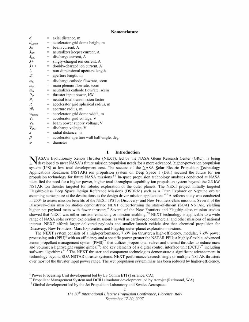
Figure 1. NEXT EM3 operating at full-power during the Long-Duration Test.
higher-specific impulse, and lower specific mass. With a predicted throughput capability more than double that of NSTAR, fewer NEXT thrusters are required compared NSTAR.
Validation of the NEXT thruster service life capability is being addressed via a comprehensive service life validation scheme utilizing a combination of test and analyses. A NEXT service life assessment was conducted at GRC employing several models to evaluate all known failure modes incorporating the results of the NEXT 2,000 h wear test conducted on an engineering model (EM) NEXT ion thruster at 6.9 kW input power. The assessment predicts the earliest failure occurring sometime after 750 kg of xenon throughput, well beyond the mission-derived propellant throughput requirement of 300 kg.16 To validate the NEXT thruster service life model and qualify the NEXT thruster, the NEXT Long-Duration Test (LDT) was initiated. The purpose of the NEXT LDT is to: 1) characterize thruster performance over the test duration, 2) measure the erosion rates of critical thruster components, 3) identify unknown life-limiting mechanisms, and 4) demonstrate 1.5 times the mission-derived propellant throughput requirement resulting in a qualification propellant throughput requirement of 450 kg. The NEXT thruster service life analyses will be updated based upon the LDT data and findings if needed.
II. Test Article The NEXT LDT is being conducted with an engineering model ion thruster, designated EM3, shown in Fig. 1.
The EM3 thruster has been modified to a flight-representative configuration so it is more comparative to the NEXT prototype-model (PM) thruster by incorporating PM ion optics and a graphite discharge cathode keeper electrode. To reduce the risk of a facility-induced failure of the thruster, the neutralizer assembly was enclosed to protect insulators from sputter deposition and all critical surfaces were grit-blasting for flake retention. The PM ion optics beam extraction diameter was reduced to 36 cm diameter to reduce outer-radius accelerator aperture erosion caused by beamlet over-focusing in these low current density regions. Reducing the ion optics beam extraction diameter from 40 cm also reduces the maximum thruster beam divergence and neutral loss rate without a significant increase in discharge losses.9 The PM ion optics geometry retains many of the key features of the EM design, however, improved manufacturing techniques implemented by a new vendor led to: better control of aperture variation as a function of grid radius, a reduced and more consistent cusp profile, and elimination of “worm track” surface problems previously encountered.14 The aperture variation for the PM accelerator grid is +1/-6% compared to +11/-16% for EM optics.14 The PM ion optics mounting scheme has been altered to eliminate the buildup and relaxation of assembly and thermally-induced stresses that lead to the decreasing ion optics’ grid-gap with test duration.17-19
One of the unexpected findings from the NSTAR Extended Life Test (ELT) was the anomalous discharge cathode keeper erosion, which was more severe and qualitatively different than prior 1,000 h and 8,200 h NSTAR wear tests.17,20,21 Due to the complete NSTAR ELT discharge cathode keeper faceplate erosion and the NEXT EM 2,000 h wear test results, a graphite discharge cathode keeper is employed on EM3, similar to the NEXT PM thruster design, to mitigate keeper erosion. The erosion rate of carbon due to the low-energy discharge plasma ion impacts is over 20 times lower than molybdenum,22 thus utilization of a graphite keeper electrode dramatically extends thruster service life.
The NEXT thruster is nominally a 0.5 – 6.9 kW input power xenon ion thruster with 2-grid ion optics, screen (+) upstream and accelerator (-) downstream. The technical approach for the NEXT design is a continuation of the derating philosophy used for the NSTAR ion thruster. A beam extraction area 1.6 times NSTAR allows higher thruster input power while maintaining low voltages and ion current densities, thus maintaining thruster longevity. The semi-conic discharge chamber utilizes a hollow cathode emitter with a ring-cusp magnetic topology created by high-strength, rare earth magnets for electron confinement. A flake retention scheme identical to that employed on the NSTAR thruster enhances the adhesion of thin films to the discharge chamber surfaces.23 New, compact propellant isolators with higher voltage isolation capability than those used by the NSTAR thruster are utilized. The NEXT neutralizer design is
The 30th International Electric Propulsion Conference, Florence, Italy
September 17-20, 2007
4
mechanically similar to the International Space Station Plasma Contactor leveraging this extensive database to reduce risk. Additional description of the NEXT EM3 thruster design can be found in Refs. 24-28.
III. Test Support Hardware The following section briefly describes the NEXT LDT supporting hardware. More detailed descriptions can be
found in Refs. 19 and 28-30.
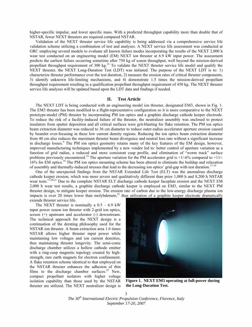
A. Vacuum Facility and Facility Diagnostics The NEXT LDT is being conducted in the 2.7
m diameter by 8.5 m long Vacuum Facility 16 (VF-16) at NASA GRC, shown in Fig. 2. VF-16 has an emergency bell jar on the end cap into which the thruster can be withdrawn and isolated in the event of a facility emergency. VF-16 is equipped with 10 cryogenic pumps for nominal thruster operation and an additional cryo-pump on the isolated bell jar for emergency use. With all 10 cryo-pumps operating, the base pressure is less than 3x10⁻⁷ Torr. Facility pressure is monitored by two ionization gauges, a glass-tube ion gauge located on the facility wall 0.5 m downstream of the thruster and a dual-filament nude near-thruster ion gauge mounted 0.5 m radially beside EM3. In addition, the isolated bell jar has an ion gauge that is turned off during normal operation. The measured facility pumping speed, corrected for xenon, is 180 kL/s using the wall-mounted ion gauge. With 10 operational cryo-pumps, the near-thruster background pressure is 2.5x10⁻⁶ Torr, corrected for xenon, when the thruster is operating at full-power. A quadrupole residual gas analyzer (RGA) measures and records the quantity of individual gas species inside VF-16 continuously every minute. All interior surfaces downstream of the thruster are lined with 1.2 cm thick graphite paneling to reduce the back-sputtered material flux to the thruster and test support hardware. The back-sputter rate, nominally 3 µm/khr, is monitored by a quartz-crystal microbalance (QCM) located next to the ion thruster. Three pinhole cameras are mounted next to the QCM and will be microscopically analyzed at the conclusion of the life test to determine the source of back-sputtered material. In addition to the pinhole cameras, five quartz witness plates are mounted along the length of the vacuum chamber wall.
B. Power Console and Xenon Feed System A power console consisting of commercially available power supplies, similar to that described in Ref. 31,
powers the ion engine. A high-purity gas feed system provides xenon to the discharge cathode, discharge chamber main plenum, and neutralizer cathode through separate mass flow controllers. Xenon can be supplied to the discharge chamber main plenum by either a mass flow controller or an engineering model propellant management system kernel provided by Aerojet.
C. Diagnostics A computerized data acquisition and control system is used to monitor and record ion engine and facility
operations. Data are sampled at a frequency range of 10-20 Hz and stored every minute. A set of data consists of individual mass flow rates, ion engine currents measured with current shunts, voltages measured with voltage dividers, facility pressures, and the QCM measurement. As part of the periodic thruster characterization, the thruster is connected to an electrically floating power supply circuit used to determine screen grid ion transparency and discharge keeper ion current. The circuit electrically ties the screen grid or discharge keeper to the discharge cathode during normal operation, but biases the screen grid or discharge keeper negative relative to discharge cathode potential to repel electrons and measure the collected ion current.
Figure 2. VF-16 at NASA GRC – end-cap opened. EM3 extends out the emergency bell jar in testing configuration.
The 30th International Electric Propulsion Conference, Florence, Italy
September 17-20, 2007
5
Ion beam diagnostics include three staggered planar probes mounted onto a translation stage to measure radial ion current density profiles and an ExB probe, or Wien Filter, to measure the doubly-to-singly charged ion signature. Each molybdenum Faraday probe has 1-cm2 circular current-collection area and is biased -30 V relative to facility ground to repel electrons. Faraday probes are fixed at axial positions of 20, 173, and 238 mm downstream of the accelerator grid. The collected currents are measured through separate isolated shunt resistors. The ExB probe is positioned 7.6 m downstream of the thruster on centerline, yielding a doubly-to-singly charged ion signature in the far-field. The ExB probe design is described in Ref. 32. The Faraday probes and ExB probe are protected from the high-energy ion beam by parking the probes outside the beam and by a graphite shutter, respectively. The LDT ion beam diagnostics are described in detail in Ref. 30.
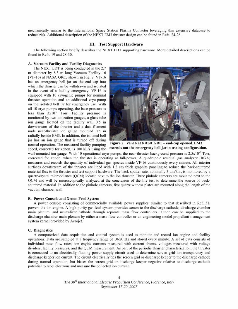
Erosion of critical ion engine components is monitored by six in-situ CCD cameras, shown in Fig. 3, which capture erosion patterns and wear rates throughout the life test. The cameras image: the downstream neutralizer keeper and cathode orifice plate, the discharge cathode keeper and cathode orifice plate, accelerator grid apertures at various radial locations from centerline, and the cold grid-gap of the thruster ion optics. The cameras are mounted to a single-axis positioning system that moves the cameras radially in front of the thruster.
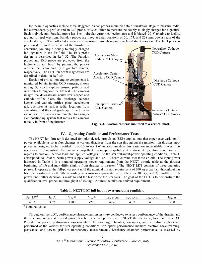
IV. Operating Condition and Performance Tests The NEXT ion thruster is designed for solar electric propulsion (SEP) applications that experience variation in
power available as solar flux changes at various distances from the sun throughout the mission. Ion thruster input power is designed to be throttled from 0.5 to 6.9 kW to accommodate this variation in available power. It is necessary to demonstrate the engine’s propellant throughput capability at a stressful operating condition with regards to erosion, thermal load, and applied voltages. The thruster full-input-power operating condition, Table 1, corresponds to 1800 V beam power supply voltage and 3.52 A beam current, met these criteria. The input power indicated in Table 1 is a nominal operating power requirement from the NEXT throttle table at the thruster beginning-of-life and may differ slightly from thruster to thruster.25 The NEXT LDT consists of three operating phases: 1) operate at the full-power point until the nominal mission requirement of 300 kg propellant throughput has been demonstrated, 2) throttle according to a mission-representative profile after 300 kg, and 3) throttle to full-power until either decision is made to end the test or the thruster fails. The goal of the LDT is to demonstrate the qualification level propellant throughput of 450 kg, 1.5 times the mission-derived requirement.
Table 1. NEXT LDT full-input-power operating condition.
PIN, kW† JB, A VB, V VA, V mM, sccm mC, sccm mN, sccm JNK, A 6.83 3.52 1800 -210 49.6 4.87 4.01 3.00
† Nominal value Throughout the LDT, performance characterization tests are conducted to assess performance of the thruster and
thruster components at several power levels that envelope the entire NEXT throttle table, listed in Table A1. Periodic component performance assessments of the discharge chamber, ion optics, and neutralizer cathode are performed at the various thruster operating conditions. Ion optics performance includes electron backstreaming, perveance, and screen grid ion transparency measurements. Discharge chamber performance is assessed by
Accelerator Mid-Radius CCD Camera
Neutralizer Cathode CCD Camera
Discharge Cathode CCD Camera
Accelerator Outer-Radius CCD Camera
Accelerator Center Aperture CCD Camera
Ion Optics’ Grid-Gap CCD Camera
Figure 3. Erosion cameras mounted to a vertical mast.
The 30th International Electric Propulsion Conference, Florence, Italy
September 17-20, 2007
6
measuring discharge losses as a function of discharge propellant utilization efficiency for fixed discharge voltages. Neutralizer performance is evaluated by measuring dc keeper voltage, ac keeper voltage, and ac keeper current as a function of neutralizer flow for a fixed neutralizer current.
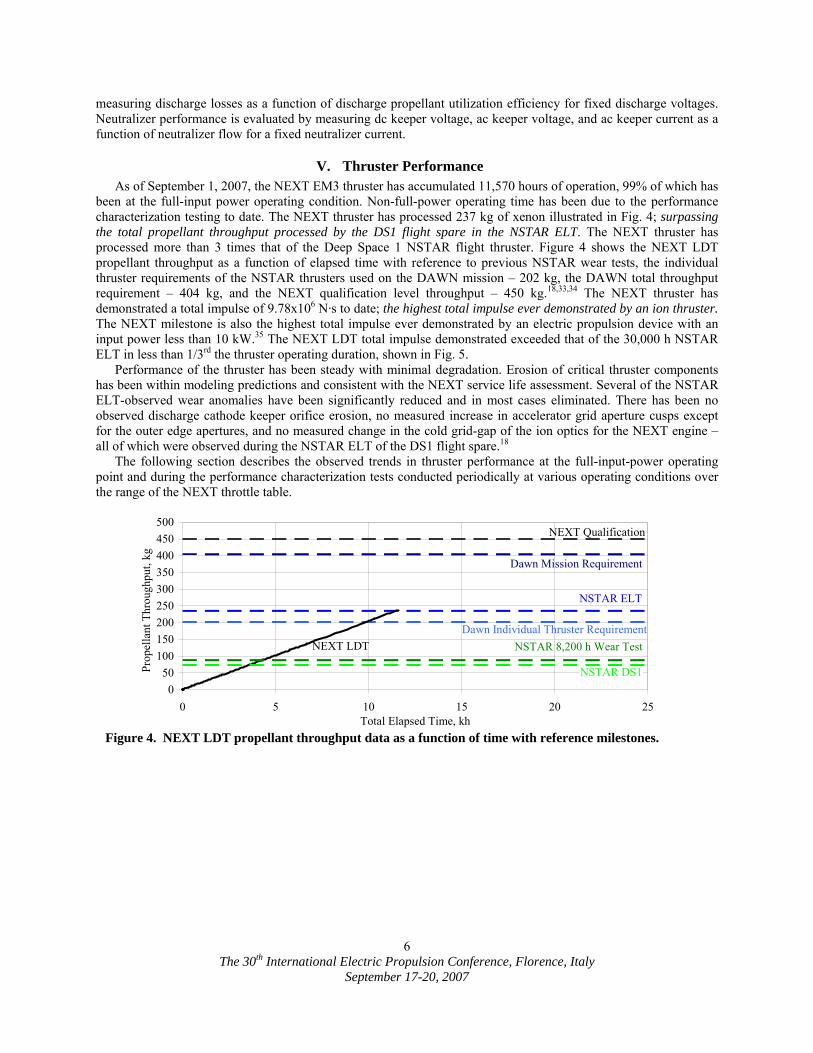
V. Thruster Performance As of September 1, 2007, the NEXT EM3 thruster has accumulated 11,570 hours of operation, 99% of which has
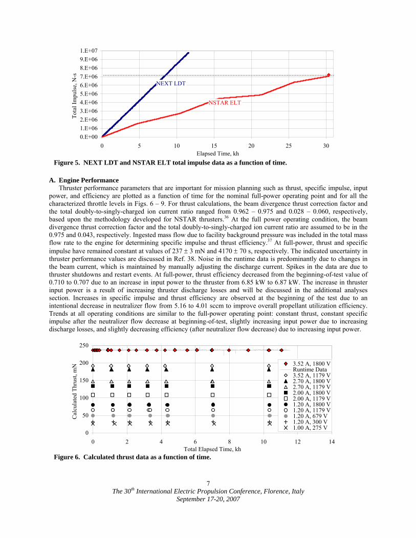
been at the full-input power operating condition. Non-full-power operating time has been due to the performance characterization testing to date. The NEXT thruster has processed 237 kg of xenon illustrated in Fig. 4; surpassing the total propellant throughput processed by the DS1 flight spare in the NSTAR ELT. The NEXT thruster has processed more than 3 times that of the Deep Space 1 NSTAR flight thruster. Figure 4 shows the NEXT LDT propellant throughput as a function of elapsed time with reference to previous NSTAR wear tests, the individual thruster requirements of the NSTAR thrusters used on the DAWN mission – 202 kg, the DAWN total throughput requirement – 404 kg, and the NEXT qualification level throughput – 450 kg.18,33,34 The NEXT thruster has demonstrated a total impulse of 9.78x10⁶ N·s to date; the highest total impulse ever demonstrated by an ion thruster. The NEXT milestone is also the highest total impulse ever demonstrated by an electric propulsion device with an input power less than 10 kW.35 The NEXT LDT total impulse demonstrated exceeded that of the 30,000 h NSTAR ELT in less than 1/3rd the thruster operating duration, shown in Fig. 5.
Performance of the thruster has been steady with minimal degradation. Erosion of critical thruster components has been within modeling predictions and consistent with the NEXT service life assessment. Several of the NSTAR ELT-observed wear anomalies have been significantly reduced and in most cases eliminated. There has been no observed discharge cathode keeper orifice erosion, no measured increase in accelerator grid aperture cusps except for the outer edge apertures, and no measured change in the cold grid-gap of the ion optics for the NEXT engine – all of which were observed during the NSTAR ELT of the DS1 flight spare.18
The following section describes the observed trends in thruster performance at the full-input-power operating point and during the performance characterization tests conducted periodically at various operating conditions over the range of the NEXT throttle table.
050
100150200250300350400450500
0 5 10 15 20 25Total Elapsed Time, kh
Prop
ella
nt T
hrou
ghpu
t, kg
.
NSTAR 8,200 h Wear TestDawn Individual Thruster Requirement
NSTAR ELT
Dawn Mission Requirement
NEXT Qualification
NSTAR DS1
NEXT LDT
Figure 4. NEXT LDT propellant throughput data as a function of time with reference milestones.
The 30th International Electric Propulsion Conference, Florence, Italy
September 17-20, 2007
7
A. Engine Performance Thruster performance parameters that are important for mission planning such as thrust, specific impulse, input
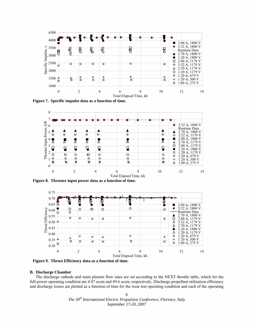
power, and efficiency are plotted as a function of time for the nominal full-power operating point and for all the characterized throttle levels in Figs. 6 – 9. For thrust calculations, the beam divergence thrust correction factor and the total doubly-to-singly-charged ion current ratio ranged from 0.962 – 0.975 and 0.028 – 0.060, respectively, based upon the methodology developed for NSTAR thrusters.36 At the full power operating condition, the beam divergence thrust correction factor and the total doubly-to-singly-charged ion current ratio are assumed to be in the 0.975 and 0.043, respectively. Ingested mass flow due to facility background pressure was included in the total mass flow rate to the engine for determining specific impulse and thrust efficiency.37 At full-power, thrust and specific impulse have remained constant at values of 237 ± 3 mN and 4170 ± 70 s, respectively. The indicated uncertainty in thruster performance values are discussed in Ref. 38. Noise in the runtime data is predominantly due to changes in the beam current, which is maintained by manually adjusting the discharge current. Spikes in the data are due to thruster shutdowns and restart events. At full-power, thrust efficiency decreased from the beginning-of-test value of 0.710 to 0.707 due to an increase in input power to the thruster from 6.85 kW to 6.87 kW. The increase in thruster input power is a result of increasing thruster discharge losses and will be discussed in the additional analyses section. Increases in specific impulse and thrust efficiency are observed at the beginning of the test due to an intentional decrease in neutralizer flow from 5.16 to 4.01 sccm to improve overall propellant utilization efficiency. Trends at all operating conditions are similar to the full-power operating point: constant thrust, constant specific impulse after the neutralizer flow decrease at beginning-of-test, slightly increasing input power due to increasing discharge losses, and slightly decreasing efficiency (after neutralizer flow decrease) due to increasing input power.
0
50
100
150
200
250
0 2 4 6 8 10 12 14Total Elapsed Time, kh
Cal
cula
ted
Thru
st, m
N . 3.52 A, 1800 V
Runtime Data3.52 A, 1179 V2.70 A, 1800 V2.70 A, 1179 V2.00 A, 1800 V2.00 A, 1179 V1.20 A, 1800 V1.20 A, 1179 V1.20 A, 679 V1.20 A, 300 V1.00 A, 275 V
Figure 6. Calculated thrust data as a function of time.
0.E+001.E+062.E+063.E+064.E+065.E+066.E+067.E+068.E+069.E+061.E+07
0 5 10 15 20 25 30Elapsed Time, kh
Tota
l Im
puls
e, N
-s .
NEXT LDT
NSTAR ELT
Figure 5. NEXT LDT and NSTAR ELT total impulse data as a function of time.
The 30th International Electric Propulsion Conference, Florence, Italy
September 17-20, 2007
8
B. Discharge Chamber The discharge cathode and main plenum flow rates are set according to the NEXT throttle table, which for the
full-power operating condition are 4.87 sccm and 49.6 sccm, respectively. Discharge propellant utilization efficiency and discharge losses are plotted as a function of time for the wear test operating condition and each of the operating
0
1
2
3
4
5
6
7
8
0 2 4 6 8 10 12 14Total Elapsed Time, kh
Thru
ster
Inpu
t Pow
er, k
W .
3.52 A, 1800 VRuntime Data2.70 A, 1800 V3.52 A, 1179 V2.00 A, 1800 V2.70 A, 1179 V2.00 A, 1179 V1.20 A, 1800 V1.20 A, 1179 V1.20 A, 679 V1.20 A, 300 V1.00 A, 275 V
Figure 8. Thruster input power data as a function of time.
0.300.350.400.450.500.550.600.650.700.75
0 2 4 6 8 10 12 14Total Elapsed Time, kh
Thru
st E
ffic
ienc
y . 2.00 A, 1800 V
3.52 A, 1800 VRuntime Data2.70 A, 1800 V2.00 A, 1179 V3.52 A, 1179 V2.70 A, 1179 V1.20 A, 1800 V1.20 A, 1179 V1.20 A, 679 V1.20 A, 300 V1.00 A, 275 V
Figure 9. Thrust Efficiency data as a function of time.
1000
1500
2000
2500
3000
3500
4000
4500
0 2 4 6 8 10 12 14Total Elapsed Time, kh
Spec
ific
Impu
lse,
s . 2.00 A, 1800 V
3.52 A, 1800 VRuntime Data2.70 A, 1800 V1.20 A, 1800 V2.00 A, 1179 V3.52 A, 1179 V2.70 A, 1179 V1.20 A, 1179 V1.20 A, 679 V1.20 A, 300 V1.00 A, 275 V
Figure 7. Specific impulse data as a function of time.
The 30th International Electric Propulsion Conference, Florence, Italy
September 17-20, 2007
9
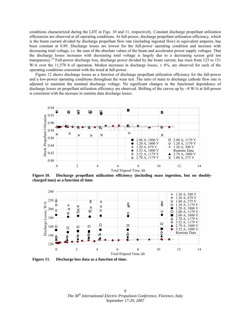
conditions characterized during the LDT in Figs. 10 and 11, respectively. Constant discharge propellant utilization efficiencies are observed at all operating conditions. At full-power, discharge propellant utilization efficiency, which is the beam current divided by discharge propellant flow rate (including ingested flow) in equivalent amperes, has been constant at 0.89. Discharge losses are lowest for the full-power operating condition and increase with decreasing total voltage, i.e. the sum of the absolute values of the beam and accelerator power supply voltages. That the discharge losses increases with decreasing total voltage is largely due to a decreasing screen grid ion transparency.26 Full-power discharge loss, discharge power divided by the beam current, has risen from 123 to 131 W/A over the 11,570 h of operation. Modest increases in discharge losses, ≤ 6%, are observed for each of the operating conditions consistent with the trend at full-power.
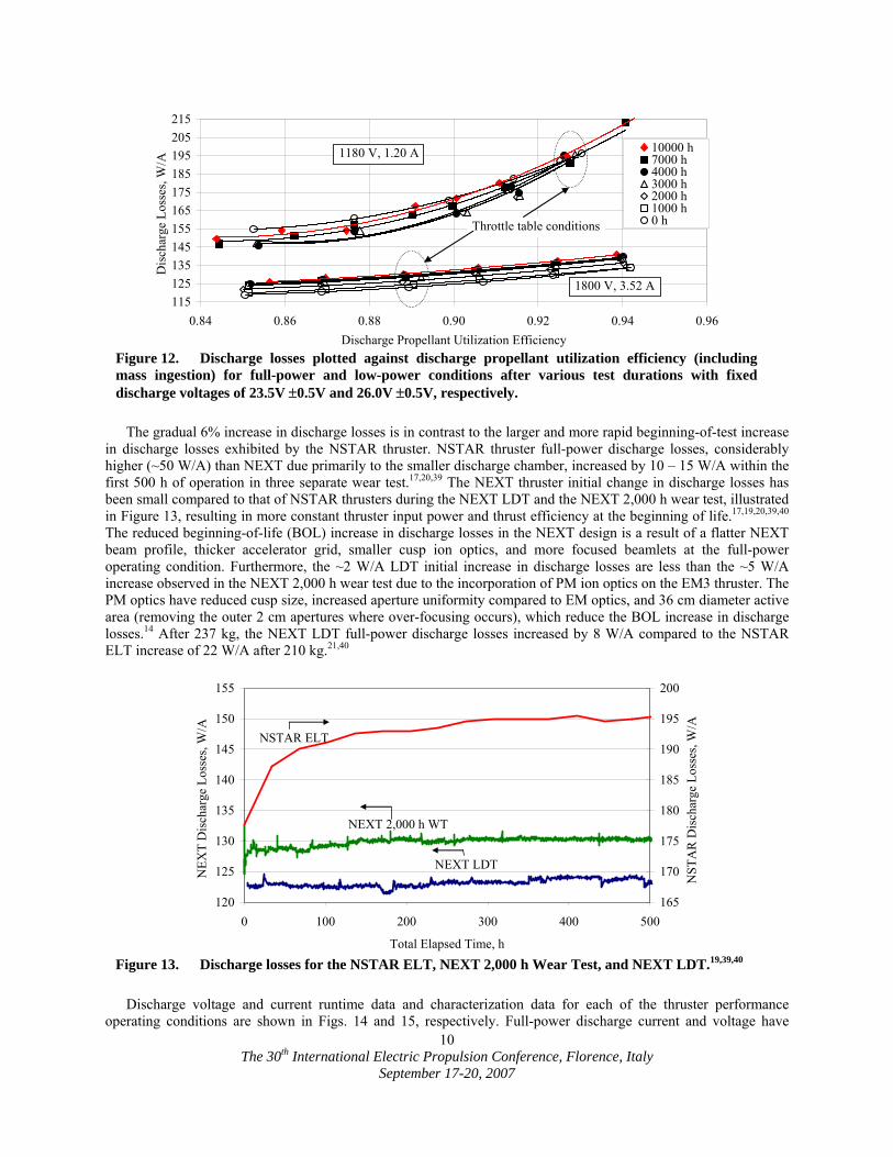
Figure 12 shows discharge losses as a function of discharge propellant utilization efficiency for the full-power and a low-power operating conditions throughout the wear test. The ratio of main to discharge cathode flow rate is adjusted to maintain the nominal discharge voltage. No significant changes in the functional dependence of discharge losses on propellant utilization efficiency are observed. Shifting of the curves up by ~8 W/A at full-power is consistent with the increase in runtime data discharge losses.
120
140
160
180
200
220
240
0 2 4 6 8 10 12 14Total Elapsed Time, kh
Dis
char
ge L
osse
s, W
/A .
1.20 A, 300 V1.20 A, 679 V1.00 A, 275 V1.20 A, 1179 V1.20 A, 1800 V2.00 A, 1179 V2.00 A, 1800 V2.70 A, 1179 V3.52 A, 1179 V2.70 A, 1800 V3.52 A, 1800 VRuntime Data
Figure 11. Discharge loss data as a function of time.
0.80
0.82
0.84
0.86
0.88
0.90
0.92
0.94
0 2 4 6 8 10 12 14Total Elapsed Time, kh
Dis
ch. P
rope
llant
Util
izat
ion
.
2.00 A, 1800 V 2.00 A, 1179 V1.20 A, 1800 V 1.20 A, 1179 V1.20 A, 679 V 1.20 A, 300 V3.52 A, 1800 V Runtime Data3.52 A, 1179 V 2.70 A, 1800 V2.70 A, 1179 V 1.00 A, 275 V
Figure 10. Discharge propellant utilization efficiency (including mass ingestion, but no doubly-charged ions) as a function of time.
The 30th International Electric Propulsion Conference, Florence, Italy
September 17-20, 2007
10
The gradual 6% increase in discharge losses is in contrast to the larger and more rapid beginning-of-test increase
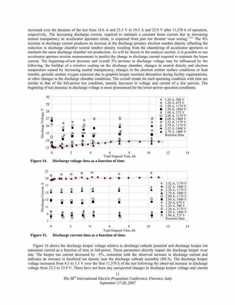
in discharge losses exhibited by the NSTAR thruster. NSTAR thruster full-power discharge losses, considerably higher (~50 W/A) than NEXT due primarily to the smaller discharge chamber, increased by 10 – 15 W/A within the first 500 h of operation in three separate wear test.17,20,39 The NEXT thruster initial change in discharge losses has been small compared to that of NSTAR thrusters during the NEXT LDT and the NEXT 2,000 h wear test, illustrated in Figure 13, resulting in more constant thruster input power and thrust efficiency at the beginning of life.17,19,20,39,40 The reduced beginning-of-life (BOL) increase in discharge losses in the NEXT design is a result of a flatter NEXT beam profile, thicker accelerator grid, smaller cusp ion optics, and more focused beamlets at the full-power operating condition. Furthermore, the ~2 W/A LDT initial increase in discharge losses are less than the ~5 W/A increase observed in the NEXT 2,000 h wear test due to the incorporation of PM ion optics on the EM3 thruster. The PM optics have reduced cusp size, increased aperture uniformity compared to EM optics, and 36 cm diameter active area (removing the outer 2 cm apertures where over-focusing occurs), which reduce the BOL increase in discharge losses.14 After 237 kg, the NEXT LDT full-power discharge losses increased by 8 W/A compared to the NSTAR ELT increase of 22 W/A after 210 kg.21,40
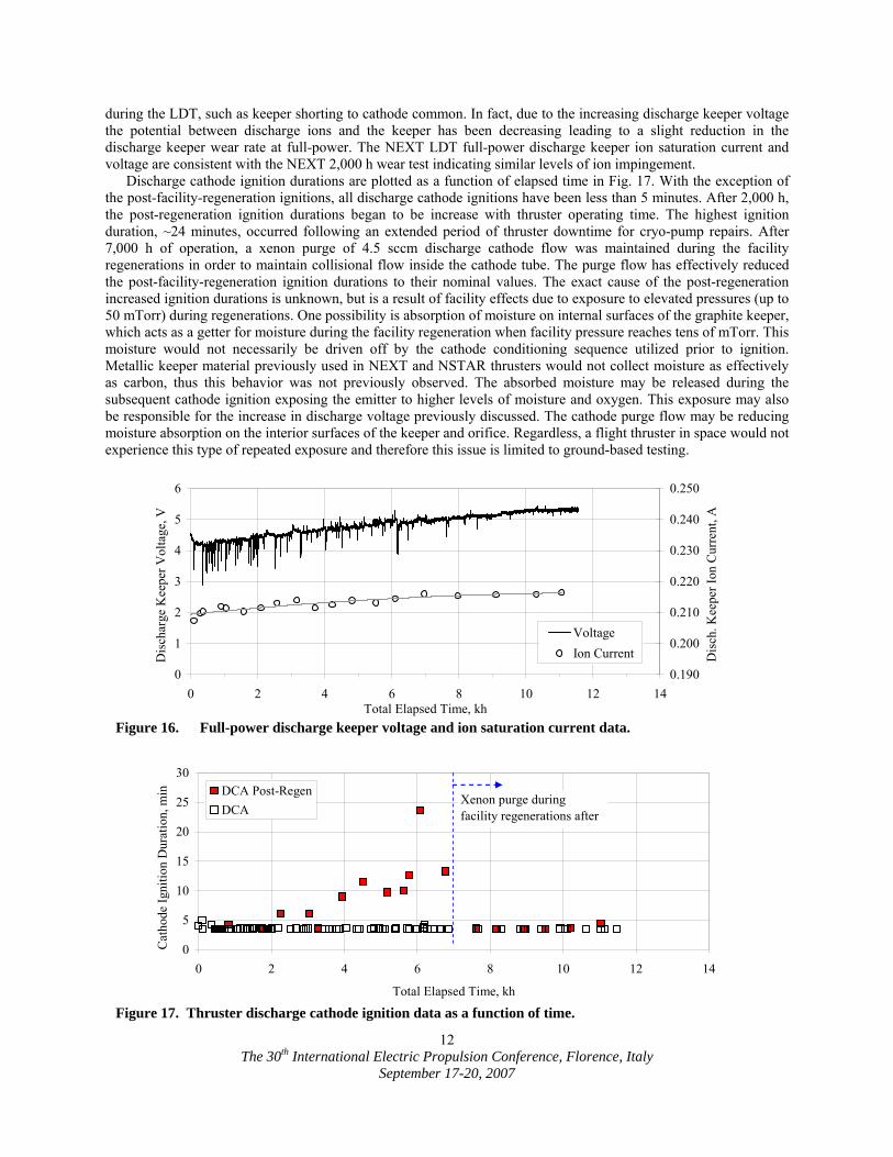
Discharge voltage and current runtime data and characterization data for each of the thruster performance
operating conditions are shown in Figs. 14 and 15, respectively. Full-power discharge current and voltage have
115125135145155165175185195205215
0.84 0.86 0.88 0.90 0.92 0.94 0.96Discharge Propellant Utilization Efficiency
Dis
char
ge L
osse
s, W
/A . 10000 h
7000 h4000 h3000 h2000 h1000 h0 hThrottle table conditions
1180 V, 1.20 A
1800 V, 3.52 A
Figure 12. Discharge losses plotted against discharge propellant utilization efficiency (including mass ingestion) for full-power and low-power conditions after various test durations with fixed discharge voltages of 23.5V ±0.5V and 26.0V ±0.5V, respectively.
120
125
130
135
140
145
150
155
0 100 200 300 400 500
Total Elapsed Time, h
NEX
T D
isch
arge
Los
ses,
W/A
.
165
170
175
180
185
190
195
200N
STA
R D
isch
arge
Los
ses,
W/A
.
NSTAR ELT
NEXT 2,000 h WT
NEXT LDT
Figure 13. Discharge losses for the NSTAR ELT, NEXT 2,000 h Wear Test, and NEXT LDT.19,39,40
The 30th International Electric Propulsion Conference, Florence, Italy
September 17-20, 2007
11
increased over the duration of the test from 18.6 A and 23.3 V to 19.3 A and 23.9 V after 11,570 h of operation, respectively. The increasing discharge current, required to maintain a constant beam current due to increasing neutral transparency as accelerator apertures erode, is expected from past ion thruster wear testing.17,21 The 4% increase in discharge current produces an increase in the discharge primary electron number density offsetting the reduction in discharge chamber neutral number density resulting from the chamfering of accelerator apertures to maintain the same discharge chamber ion production. As will be shown in the analysis section, it is possible to use accelerator aperture erosion measurements to predict the change in discharge current required to maintain the beam current. The beginning-of-test decrease and overall 3% increase in discharge voltage may be influenced by the following: the buildup of a resistive coating on the discharge chamber, changes in neutral density and electron temperature caused by increasing neutral transparency, changes in the electron emitter surface conditions or heat transfer, periodic emitter oxygen exposure due to graphite keeper moisture absorption during facility regenerations, or other changes in the discharge chamber conditions. The overall trends for each operating condition with time are similar to that of the full-power test condition, namely increases in voltage and current of a few percent. The beginning of test decrease in discharge voltage is more pronounced for the lower-power operation conditions.
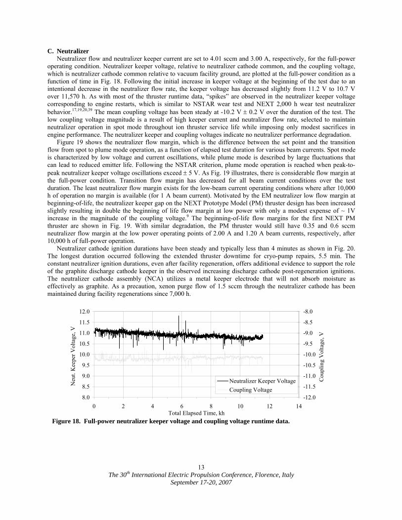
Figure 16 shows the discharge keeper voltage relative to discharge cathode potential and discharge keeper ion
saturation current as a function of time at full-power. These parameters directly impact the discharge keeper wear rate. The keeper ion current increased by ~5%, consistent with the observed increase in discharge current and indicates an increase in localized ion density near the discharge cathode assembly (DCA). The discharge keeper voltage increased from 4.3 to 5.3 V over the first 11,570 h of the test following the observed increase in discharge voltage from 23.3 to 23.9 V. There have not been any unexpected changes in discharge keeper voltage and current
7
9
11
13
15
17
19
21
0 2 4 6 8 10 12 14Total Elapsed Time, kh
Dis
char
ge C
urre
nt, A
. 3.52 A, 1179 V3.52 A, 1800 V2.70 A, 1179 V2.70 A, 1800 V2.00 A, 1179 V2.00 A, 1800 V1.20 A, 679 V1.20 A, 300 V1.20 A, 1179 V1.20 A, 1800 V1.00 A, 275 VRuntime Data
Figure 15. Discharge current data as a function of time.
23
24
25
26
27
28
29
30
0 2 4 6 8 10 12 14Total Elapsed Time, kh
Dis
char
ge V
olta
ge, V
.
1.20 A, 300 V1.20 A, 679 V1.20 A, 1179 V1.20 A, 1800 V1.00 A, 275 V2.00 A, 1179 V2.00 A, 1800 V3.52 A, 1179 V2.70 A, 1179 V3.52 A, 1800 V2.70 A, 1800 VRuntime Data
Figure 14. Discharge voltage data as a function of time.
The 30th International Electric Propulsion Conference, Florence, Italy
September 17-20, 2007
12
during the LDT, such as keeper shorting to cathode common. In fact, due to the increasing discharge keeper voltage the potential between discharge ions and the keeper has been decreasing leading to a slight reduction in the discharge keeper wear rate at full-power. The NEXT LDT full-power discharge keeper ion saturation current and voltage are consistent with the NEXT 2,000 h wear test indicating similar levels of ion impingement.
Discharge cathode ignition durations are plotted as a function of elapsed time in Fig. 17. With the exception of the post-facility-regeneration ignitions, all discharge cathode ignitions have been less than 5 minutes. After 2,000 h, the post-regeneration ignition durations began to be increase with thruster operating time. The highest ignition duration, ~24 minutes, occurred following an extended period of thruster downtime for cryo-pump repairs. After 7,000 h of operation, a xenon purge of 4.5 sccm discharge cathode flow was maintained during the facility regenerations in order to maintain collisional flow inside the cathode tube. The purge flow has effectively reduced the post-facility-regeneration ignition durations to their nominal values. The exact cause of the post-regeneration increased ignition durations is unknown, but is a result of facility effects due to exposure to elevated pressures (up to 50 mTorr) during regenerations. One possibility is absorption of moisture on internal surfaces of the graphite keeper, which acts as a getter for moisture during the facility regeneration when facility pressure reaches tens of mTorr. This moisture would not necessarily be driven off by the cathode conditioning sequence utilized prior to ignition. Metallic keeper material previously used in NEXT and NSTAR thrusters would not collect moisture as effectively as carbon, thus this behavior was not previously observed. The absorbed moisture may be released during the subsequent cathode ignition exposing the emitter to higher levels of moisture and oxygen. This exposure may also be responsible for the increase in discharge voltage previously discussed. The cathode purge flow may be reducing moisture absorption on the interior surfaces of the keeper and orifice. Regardless, a flight thruster in space would not experience this type of repeated exposure and therefore this issue is limited to ground-based testing.
0
5
10
15
20
25
30
0 2 4 6 8 10 12 14
Total Elapsed Time, kh
Cat
hode
Igni
tion
Dur
atio
n, m
in
,
DCA Post-RegenDCA
Xenon purge during facility regenerations after
Figure 17. Thruster discharge cathode ignition data as a function of time.
0
1
2
3
4
5
6
0 2 4 6 8 10 12 14Total Elapsed Time, kh
Dis
char
ge K
eepe
r Vol
tage
, V .
0.190
0.200
0.210
0.220
0.230
0.240
0.250
Dis
ch. K
eepe
r Ion
Cur
rent
, A .
VoltageIon Current
Figure 16. Full-power discharge keeper voltage and ion saturation current data.
The 30th International Electric Propulsion Conference, Florence, Italy
September 17-20, 2007
13
C. Neutralizer Neutralizer flow and neutralizer keeper current are set to 4.01 sccm and 3.00 A, respectively, for the full-power
operating condition. Neutralizer keeper voltage, relative to neutralizer cathode common, and the coupling voltage, which is neutralizer cathode common relative to vacuum facility ground, are plotted at the full-power condition as a function of time in Fig. 18. Following the initial increase in keeper voltage at the beginning of the test due to an intentional decrease in the neutralizer flow rate, the keeper voltage has decreased slightly from 11.2 V to 10.7 V over 11,570 h. As with most of the thruster runtime data, “spikes” are observed in the neutralizer keeper voltage corresponding to engine restarts, which is similar to NSTAR wear test and NEXT 2,000 h wear test neutralizer behavior.17,19,20,39 The mean coupling voltage has been steady at -10.2 V ± 0.2 V over the duration of the test. The low coupling voltage magnitude is a result of high keeper current and neutralizer flow rate, selected to maintain neutralizer operation in spot mode throughout ion thruster service life while imposing only modest sacrifices in engine performance. The neutralizer keeper and coupling voltages indicate no neutralizer performance degradation.
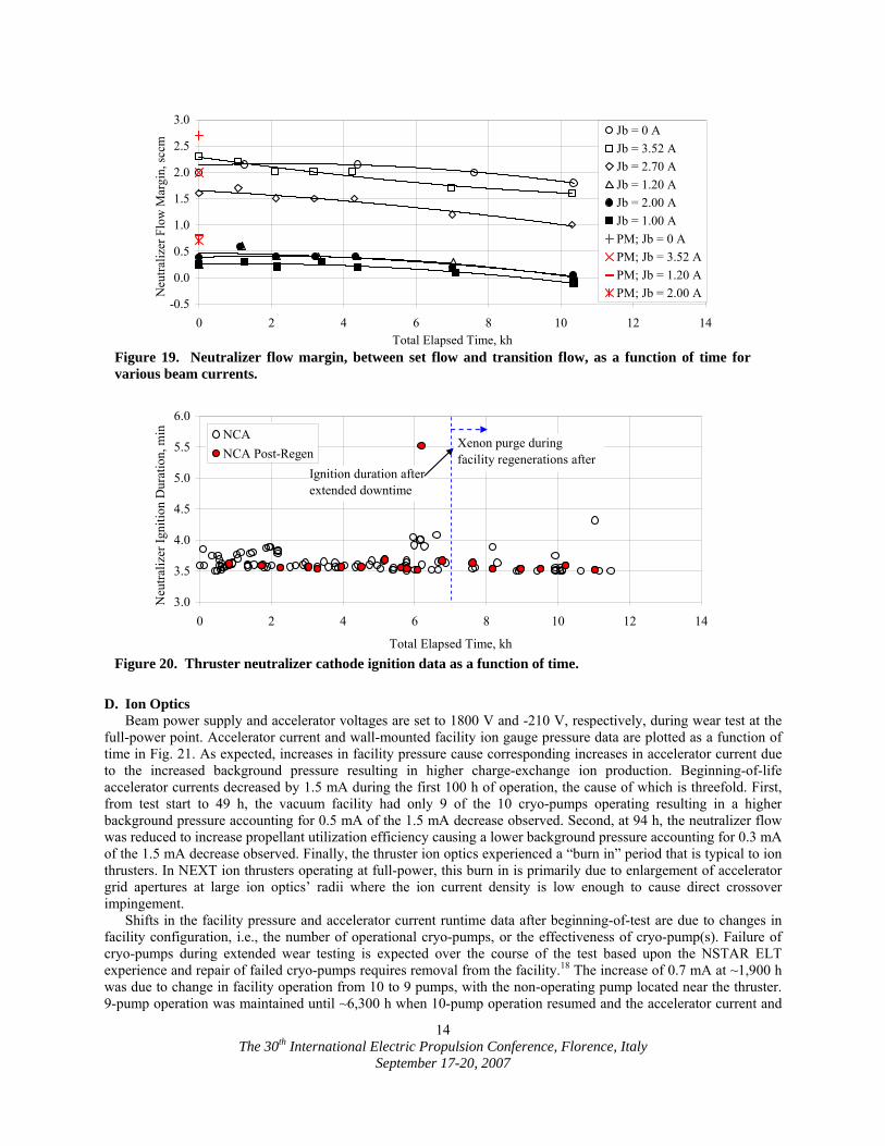
Figure 19 shows the neutralizer flow margin, which is the difference between the set point and the transition flow from spot to plume mode operation, as a function of elapsed test duration for various beam currents. Spot mode is characterized by low voltage and current oscillations, while plume mode is described by large fluctuations that can lead to reduced emitter life. Following the NSTAR criterion, plume mode operation is reached when peak-to-peak neutralizer keeper voltage oscillations exceed ± 5 V. As Fig. 19 illustrates, there is considerable flow margin at the full-power condition. Transition flow margin has decreased for all beam current conditions over the test duration. The least neutralizer flow margin exists for the low-beam current operating conditions where after 10,000 h of operation no margin is available (for 1 A beam current). Motivated by the EM neutralizer low flow margin at beginning-of-life, the neutralizer keeper gap on the NEXT Prototype Model (PM) thruster design has been increased slightly resulting in double the beginning of life flow margin at low power with only a modest expense of ~ 1V increase in the magnitude of the coupling voltage.9 The beginning-of-life flow margins for the first NEXT PM thruster are shown in Fig. 19. With similar degradation, the PM thruster would still have 0.35 and 0.6 sccm neutralizer flow margin at the low power operating points of 2.00 A and 1.20 A beam currents, respectively, after 10,000 h of full-power operation.
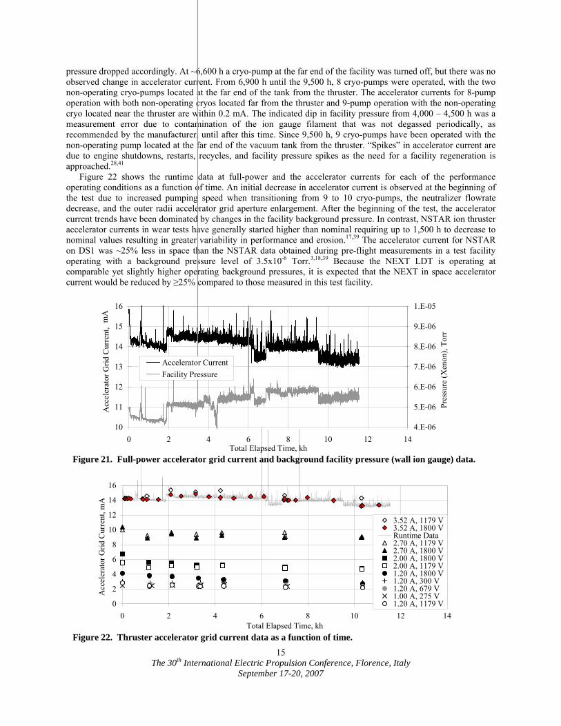
Neutralizer cathode ignition durations have been steady and typically less than 4 minutes as shown in Fig. 20. The longest duration occurred following the extended thruster downtime for cryo-pump repairs, 5.5 min. The constant neutralizer ignition durations, even after facility regeneration, offers additional evidence to support the role of the graphite discharge cathode keeper in the observed increasing discharge cathode post-regeneration ignitions. The neutralizer cathode assembly (NCA) utilizes a metal keeper electrode that will not absorb moisture as effectively as graphite. As a precaution, xenon purge flow of 1.5 sccm through the neutralizer cathode has been maintained during facility regenerations since 7,000 h.
8.0
8.5
9.0
9.5
10.0
10.5
11.0
11.5
12.0
0 2 4 6 8 10 12 14Total Elapsed Time, kh
Neu
t. K
eepe
r Vol
tage
, V .
-12.0
-11.5
-11.0
-10.5
-10.0
-9.5
-9.0
-8.5
-8.0C
oupl
ing
Vol
tage
, V .
Neutralizer Keeper VoltageCoupling Voltage
Figure 18. Full-power neutralizer keeper voltage and coupling voltage runtime data.
The 30th International Electric Propulsion Conference, Florence, Italy
September 17-20, 2007
14
D. Ion Optics Beam power supply and accelerator voltages are set to 1800 V and -210 V, respectively, during wear test at the
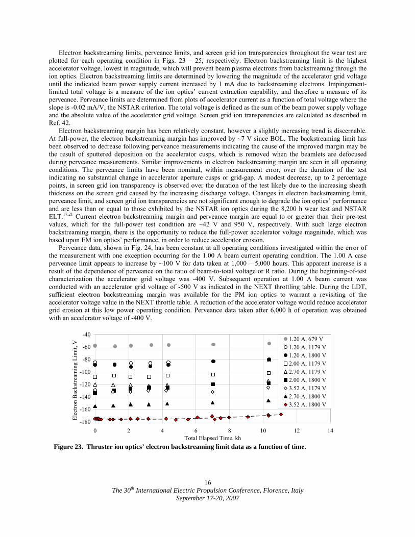
full-power point. Accelerator current and wall-mounted facility ion gauge pressure data are plotted as a function of time in Fig. 21. As expected, increases in facility pressure cause corresponding increases in accelerator current due to the increased background pressure resulting in higher charge-exchange ion production. Beginning-of-life accelerator currents decreased by 1.5 mA during the first 100 h of operation, the cause of which is threefold. First, from test start to 49 h, the vacuum facility had only 9 of the 10 cryo-pumps operating resulting in a higher background pressure accounting for 0.5 mA of the 1.5 mA decrease observed. Second, at 94 h, the neutralizer flow was reduced to increase propellant utilization efficiency causing a lower background pressure accounting for 0.3 mA of the 1.5 mA decrease observed. Finally, the thruster ion optics experienced a “burn in” period that is typical to ion thrusters. In NEXT ion thrusters operating at full-power, this burn in is primarily due to enlargement of accelerator grid apertures at large ion optics’ radii where the ion current density is low enough to cause direct crossover impingement.
Shifts in the facility pressure and accelerator current runtime data after beginning-of-test are due to changes in facility configuration, i.e., the number of operational cryo-pumps, or the effectiveness of cryo-pump(s). Failure of cryo-pumps during extended wear testing is expected over the course of the test based upon the NSTAR ELT experience and repair of failed cryo-pumps requires removal from the facility.18 The increase of 0.7 mA at ~1,900 h was due to change in facility operation from 10 to 9 pumps, with the non-operating pump located near the thruster. 9-pump operation was maintained until ~6,300 h when 10-pump operation resumed and the accelerator current and
3.0
3.5
4.0
4.5
5.0
5.5
6.0
0 2 4 6 8 10 12 14
Total Elapsed Time, kh
Neu
traliz
er Ig
nitio
n D
urat
ion,
min
,
NCANCA Post-Regen
Ignition duration after extended downtime
Xenon purge during facility regenerations after
Figure 20. Thruster neutralizer cathode ignition data as a function of time.
-0.5
0.0
0.5
1.0
1.5
2.0
2.5
3.0
0 2 4 6 8 10 12 14Total Elapsed Time, kh
Neu
traliz
er F
low
Mar
gin,
sccm
. Jb = 0 AJb = 3.52 AJb = 2.70 AJb = 1.20 AJb = 2.00 AJb = 1.00 APM; Jb = 0 APM; Jb = 3.52 APM; Jb = 1.20 APM; Jb = 2.00 A
Figure 19. Neutralizer flow margin, between set flow and transition flow, as a function of time for various beam currents.
The 30th International Electric Propulsion Conference, Florence, Italy
September 17-20, 2007
15
pressure dropped accordingly. At ~6,600 h a cryo-pump at the far end of the facility was turned off, but there was no observed change in accelerator current. From 6,900 h until the 9,500 h, 8 cryo-pumps were operated, with the two non-operating cryo-pumps located at the far end of the tank from the thruster. The accelerator currents for 8-pump operation with both non-operating cryos located far from the thruster and 9-pump operation with the non-operating cryo located near the thruster are within 0.2 mA. The indicated dip in facility pressure from 4,000 – 4,500 h was a measurement error due to contamination of the ion gauge filament that was not degassed periodically, as recommended by the manufacturer, until after this time. Since 9,500 h, 9 cryo-pumps have been operated with the non-operating pump located at the far end of the vacuum tank from the thruster. “Spikes” in accelerator current are due to engine shutdowns, restarts, recycles, and facility pressure spikes as the need for a facility regeneration is approached.28,41
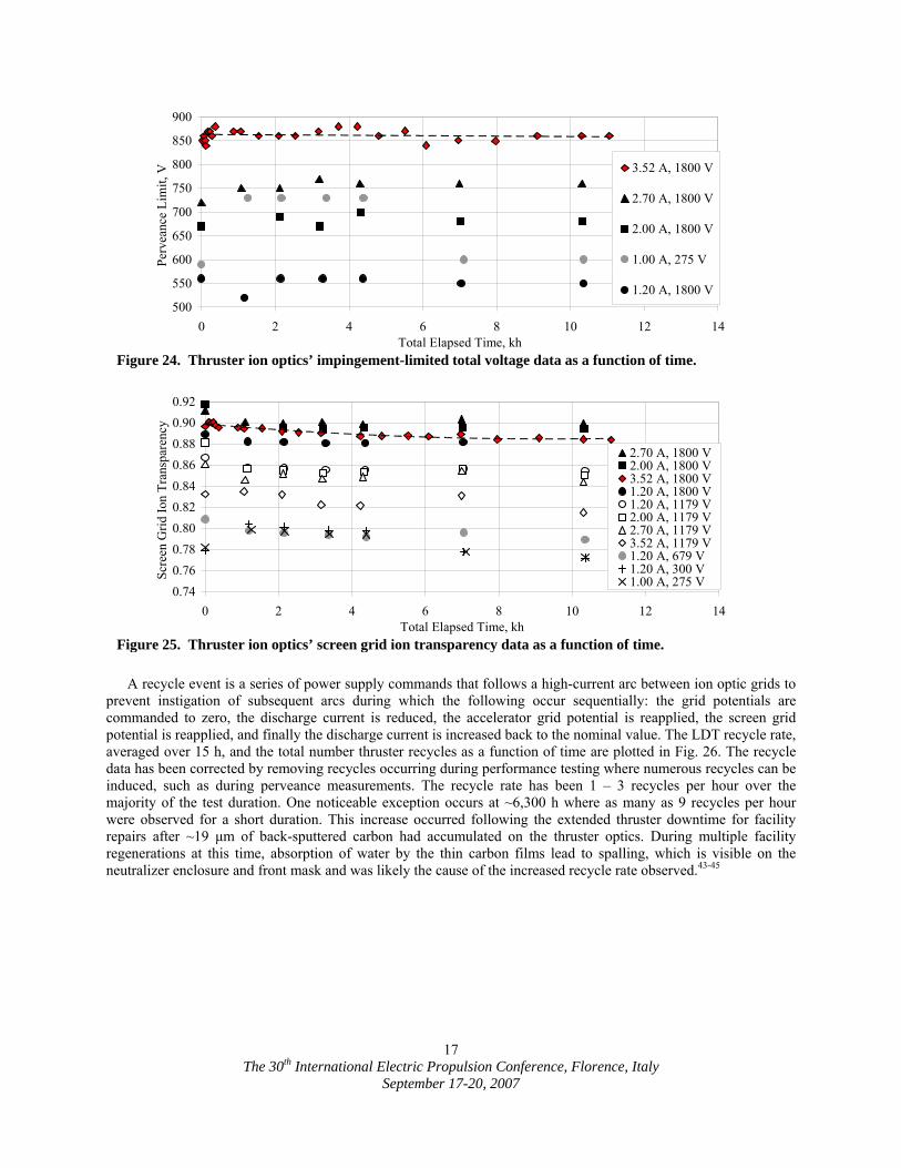
Figure 22 shows the runtime data at full-power and the accelerator currents for each of the performance operating conditions as a function of time. An initial decrease in accelerator current is observed at the beginning of the test due to increased pumping speed when transitioning from 9 to 10 cryo-pumps, the neutralizer flowrate decrease, and the outer radii accelerator grid aperture enlargement. After the beginning of the test, the accelerator current trends have been dominated by changes in the facility background pressure. In contrast, NSTAR ion thruster accelerator currents in wear tests have generally started higher than nominal requiring up to 1,500 h to decrease to nominal values resulting in greater variability in performance and erosion.17,39 The accelerator current for NSTAR on DS1 was ~25% less in space than the NSTAR data obtained during pre-flight measurements in a test facility operating with a background pressure level of 3.5x10⁻⁶ Torr.3,18,39 Because the NEXT LDT is operating at comparable yet slightly higher operating background pressures, it is expected that the NEXT in space accelerator current would be reduced by ≥25% compared to those measured in this test facility.
0
2
4
6
8
10
12
14
16
0 2 4 6 8 10 12 14Total Elapsed Time, kh
Acc
eler
ator
Grid
Cur
rent
, mA
.
3.52 A, 1179 V3.52 A, 1800 VRuntime Data2.70 A, 1179 V2.70 A, 1800 V2.00 A, 1800 V2.00 A, 1179 V1.20 A, 1800 V1.20 A, 300 V1.20 A, 679 V1.00 A, 275 V1.20 A, 1179 V
Figure 22. Thruster accelerator grid current data as a function of time.
10
11
12
13
14
15
16
0 2 4 6 8 10 12 14Total Elapsed Time, kh
Acc
eler
ator
Grid
Cur
rent
, ,
4.E-06
5.E-06
6.E-06
7.E-06
8.E-06
9.E-06
1.E-05
Pres
sure
(Xen
on),
Torr
.
Accelerator CurrentFacility Pressure
mA
Figure 21. Full-power accelerator grid current and background facility pressure (wall ion gauge) data.
The 30th International Electric Propulsion Conference, Florence, Italy
September 17-20, 2007
16
Electron backstreaming limits, perveance limits, and screen grid ion transparencies throughout the wear test are plotted for each operating condition in Figs. 23 – 25, respectively. Electron backstreaming limit is the highest accelerator voltage, lowest in magnitude, which will prevent beam plasma electrons from backstreaming through the ion optics. Electron backstreaming limits are determined by lowering the magnitude of the accelerator grid voltage until the indicated beam power supply current increased by 1 mA due to backstreaming electrons. Impingement-limited total voltage is a measure of the ion optics’ current extraction capability, and therefore a measure of its perveance. Perveance limits are determined from plots of accelerator current as a function of total voltage where the slope is -0.02 mA/V, the NSTAR criterion. The total voltage is defined as the sum of the beam power supply voltage and the absolute value of the accelerator grid voltage. Screen grid ion transparencies are calculated as described in Ref. 42.
Electron backstreaming margin has been relatively constant, however a slightly increasing trend is discernable. At full-power, the electron backstreaming margin has improved by ~7 V since BOL. The backstreaming limit has been observed to decrease following perveance measurements indicating the cause of the improved margin may be the result of sputtered deposition on the accelerator cusps, which is removed when the beamlets are defocused during perveance measurements. Similar improvements in electron backstreaming margin are seen in all operating conditions. The perveance limits have been nominal, within measurement error, over the duration of the test indicating no substantial change in accelerator aperture cusps or grid-gap. A modest decrease, up to 2 percentage points, in screen grid ion transparency is observed over the duration of the test likely due to the increasing sheath thickness on the screen grid caused by the increasing discharge voltage. Changes in electron backstreaming limit, perveance limit, and screen grid ion transparencies are not significant enough to degrade the ion optics’ performance and are less than or equal to those exhibited by the NSTAR ion optics during the 8,200 h wear test and NSTAR ELT.17,21 Current electron backstreaming margin and perveance margin are equal to or greater than their pre-test values, which for the full-power test condition are ~42 V and 950 V, respectively. With such large electron backstreaming margin, there is the opportunity to reduce the full-power accelerator voltage magnitude, which was based upon EM ion optics’ performance, in order to reduce accelerator erosion.
Perveance data, shown in Fig. 24, has been constant at all operating conditions investigated within the error of the measurement with one exception occurring for the 1.00 A beam current operating condition. The 1.00 A case perveance limit appears to increase by ~100 V for data taken at 1,000 – 5,000 hours. This apparent increase is a result of the dependence of perveance on the ratio of beam-to-total voltage or R ratio. During the beginning-of-test characterization the accelerator grid voltage was -400 V. Subsequent operation at 1.00 A beam current was conducted with an accelerator grid voltage of -500 V as indicated in the NEXT throttling table. During the LDT, sufficient electron backstreaming margin was available for the PM ion optics to warrant a revisiting of the accelerator voltage value in the NEXT throttle table. A reduction of the accelerator voltage would reduce accelerator grid erosion at this low power operating condition. Perveance data taken after 6,000 h of operation was obtained with an accelerator voltage of -400 V.
-180
-160
-140
-120
-100
-80
-60
-40
0 2 4 6 8 10 12 14Total Elapsed Time, kh
Elec
tron
Bac
kstre
amin
g Li
mit,
V . 1.20 A, 679 V
1.20 A, 1179 V1.20 A, 1800 V2.00 A, 1179 V2.70 A, 1179 V2.00 A, 1800 V3.52 A, 1179 V2.70 A, 1800 V3.52 A, 1800 V
Figure 23. Thruster ion optics’ electron backstreaming limit data as a function of time.
The 30th International Electric Propulsion Conference, Florence, Italy
September 17-20, 2007
17
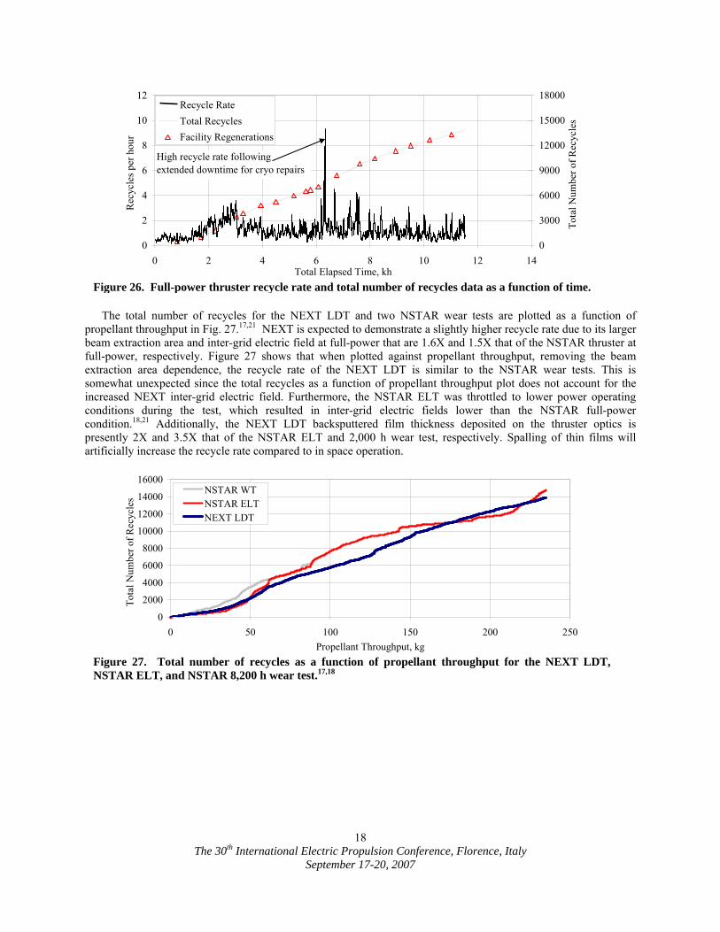
A recycle event is a series of power supply commands that follows a high-current arc between ion optic grids to prevent instigation of subsequent arcs during which the following occur sequentially: the grid potentials are commanded to zero, the discharge current is reduced, the accelerator grid potential is reapplied, the screen grid potential is reapplied, and finally the discharge current is increased back to the nominal value. The LDT recycle rate, averaged over 15 h, and the total number thruster recycles as a function of time are plotted in Fig. 26. The recycle data has been corrected by removing recycles occurring during performance testing where numerous recycles can be induced, such as during perveance measurements. The recycle rate has been 1 – 3 recycles per hour over the majority of the test duration. One noticeable exception occurs at ~6,300 h where as many as 9 recycles per hour were observed for a short duration. This increase occurred following the extended thruster downtime for facility repairs after ~19 µm of back-sputtered carbon had accumulated on the thruster optics. During multiple facility regenerations at this time, absorption of water by the thin carbon films lead to spalling, which is visible on the neutralizer enclosure and front mask and was likely the cause of the increased recycle rate observed.43-45
0.740.760.780.800.820.840.860.880.900.92
0 2 4 6 8 10 12 14Total Elapsed Time, kh
Scre
en G
rid Io
n Tr
ansp
aren
cy .
2.70 A, 1800 V2.00 A, 1800 V3.52 A, 1800 V1.20 A, 1800 V1.20 A, 1179 V2.00 A, 1179 V2.70 A, 1179 V3.52 A, 1179 V1.20 A, 679 V1.20 A, 300 V1.00 A, 275 V
Figure 25. Thruster ion optics’ screen grid ion transparency data as a function of time.
500
550
600
650
700
750
800
850
900
0 2 4 6 8 10 12 14Total Elapsed Time, kh
Perv
eanc
e Li
mit,
V . 3.52 A, 1800 V
2.70 A, 1800 V
2.00 A, 1800 V
1.00 A, 275 V
1.20 A, 1800 V
Figure 24. Thruster ion optics’ impingement-limited total voltage data as a function of time.
The 30th International Electric Propulsion Conference, Florence, Italy
September 17-20, 2007
18
The total number of recycles for the NEXT LDT and two NSTAR wear tests are plotted as a function of
propellant throughput in Fig. 27.17,21 NEXT is expected to demonstrate a slightly higher recycle rate due to its larger beam extraction area and inter-grid electric field at full-power that are 1.6X and 1.5X that of the NSTAR thruster at full-power, respectively. Figure 27 shows that when plotted against propellant throughput, removing the beam extraction area dependence, the recycle rate of the NEXT LDT is similar to the NSTAR wear tests. This is somewhat unexpected since the total recycles as a function of propellant throughput plot does not account for the increased NEXT inter-grid electric field. Furthermore, the NSTAR ELT was throttled to lower power operating conditions during the test, which resulted in inter-grid electric fields lower than the NSTAR full-power condition.18,21 Additionally, the NEXT LDT backsputtered film thickness deposited on the thruster optics is presently 2X and 3.5X that of the NSTAR ELT and 2,000 h wear test, respectively. Spalling of thin films will artificially increase the recycle rate compared to in space operation.
0
2
4
6
8
10
12
0 2 4 6 8 10 12 14Total Elapsed Time, kh
Rec
ycle
s per
hou
r .
0
3000
6000
9000
12000
15000
18000
Tota
l Num
ber o
f Rec
ycle
s .Recycle Rate
Total RecyclesFacility Regenerations
High recycle rate followingextended downtime for cryo repairs
Figure 26. Full-power thruster recycle rate and total number of recycles data as a function of time.
0
2000
4000
6000
8000
10000
12000
14000
16000
0 50 100 150 200 250Propellant Throughput, kg
Tota
l Num
ber o
f Rec
ycle
s . NSTAR WT
NSTAR ELTNEXT LDT
Figure 27. Total number of recycles as a function of propellant throughput for the NEXT LDT, NSTAR ELT, and NSTAR 8,200 h wear test.17,18
The 30th International Electric Propulsion Conference, Florence, Italy
September 17-20, 2007
19
VI. Beam Diagnostics and In-Situ Erosion Results The plume diagnostics and erosion measurement results of the NEXT LDT are presented in this section. A
number of high risk or life-limiting items were identified from the DS1 flight spare ELT. The results of the NSTAR ELT were considered and design changes made in the NEXT design to reduce or mitigate thruster failure modes and high risk items listed in Table 2.
Table 2. NSTAR ELT thruster high risk items, erosion phenomena, and NEXT thruster mitigation strategies.
NSTAR ELT Issue NEXT Mitigation Strategy NEXT LDT Observations Discharge cathode short (after 5850 h, 56 kg) and keeper faceplate completely eroded away exposing cathode.
Cathode keeper material changed to graphite to reduce sputter yield and erosion rate.
No short or keeper orifice diameter erosion observed. Substantial margin on keeper orifice plate erosion from 2,000 h wear test.19
Pit and groove erosion through the accelerator grid evident in post-test analysis.
Thicker accelerator grid to achieve longer life.
Groove erosion measurements indicate 700-800 kg propellant throughput before eroded through.
Ion optics cold grid-gap 30% decrease over test duration.
Redesigned ion optics mounting ring to better manage thermal stresses.
In-situ cold grid-gap measurement constant over test duration to date.
Electron backstreaming limit reached throttle value for full-power operation after ~10, 900 h (92 kg).
Thick accelerator grid optics utilized, highly focused beamlets at full-power reduce cusp erosion, and grid-gap decrease mitigated.
Electron backstreaming limit has slightly decreased for all operating conditions over test duration. Negligible cusp erosion to date.
Evidence of arc-tracking in low-voltage propellant isolator.
Low-voltage isolator eliminated. Isolation maintained by the high-voltage propellant isolator.
High impedance measured from anode to discharge cathode to date.
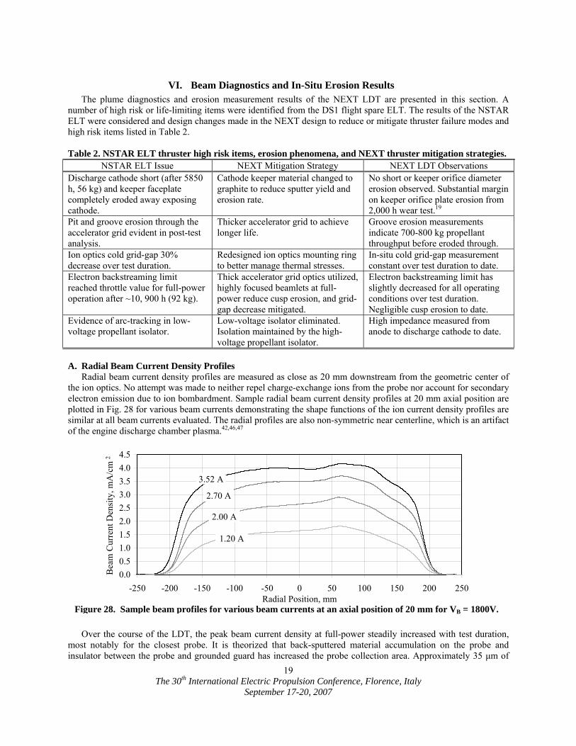
A. Radial Beam Current Density Profiles Radial beam current density profiles are measured as close as 20 mm downstream from the geometric center of
the ion optics. No attempt was made to neither repel charge-exchange ions from the probe nor account for secondary electron emission due to ion bombardment. Sample radial beam current density profiles at 20 mm axial position are plotted in Fig. 28 for various beam currents demonstrating the shape functions of the ion current density profiles are similar at all beam currents evaluated. The radial profiles are also non-symmetric near centerline, which is an artifact of the engine discharge chamber plasma.42,46,47
Over the course of the LDT, the peak beam current density at full-power steadily increased with test duration, most notably for the closest probe. It is theorized that back-sputtered material accumulation on the probe and insulator between the probe and grounded guard has increased the probe collection area. Approximately 35 µm of
0.00.51.01.52.02.53.03.54.04.5
-250 -200 -150 -100 -50 0 50 100 150 200 250Radial Position, mm
Bea
m C
urre
nt D
ensi
ty, m
A/c
m .2
3.52 A
2.70 A
2.00 A
1.20 A
Figure 28. Sample beam profiles for various beam currents at an axial position of 20 mm for VB = 1800V.
The 30th International Electric Propulsion Conference, Florence, Italy
September 17-20, 2007
20
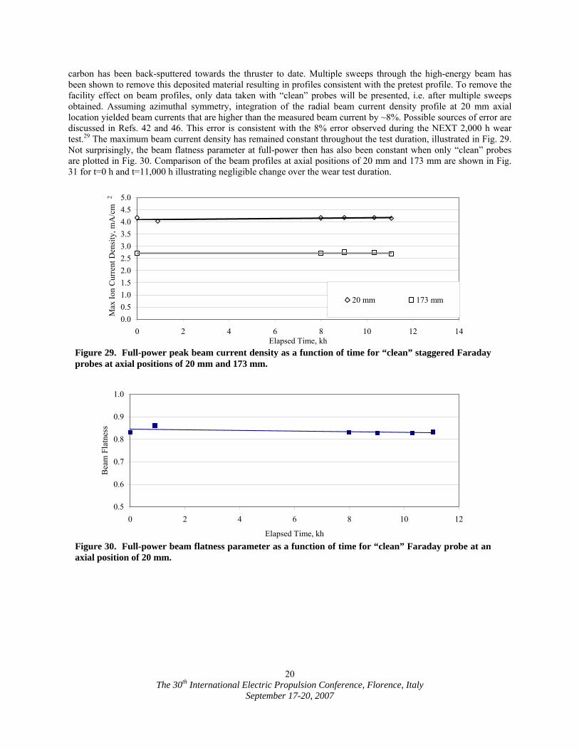
carbon has been back-sputtered towards the thruster to date. Multiple sweeps through the high-energy beam has been shown to remove this deposited material resulting in profiles consistent with the pretest profile. To remove the facility effect on beam profiles, only data taken with “clean” probes will be presented, i.e. after multiple sweeps obtained. Assuming azimuthal symmetry, integration of the radial beam current density profile at 20 mm axial location yielded beam currents that are higher than the measured beam current by ~8%. Possible sources of error are discussed in Refs. 42 and 46. This error is consistent with the 8% error observed during the NEXT 2,000 h wear test.29 The maximum beam current density has remained constant throughout the test duration, illustrated in Fig. 29. Not surprisingly, the beam flatness parameter at full-power then has also been constant when only “clean” probes are plotted in Fig. 30. Comparison of the beam profiles at axial positions of 20 mm and 173 mm are shown in Fig. 31 for t=0 h and t=11,000 h illustrating negligible change over the wear test duration.
0.5
0.6
0.7
0.8
0.9
1.0
0 2 4 6 8 10 12
Elapsed Time, kh
Bea
m F
latn
ess
Figure 30. Full-power beam flatness parameter as a function of time for “clean” Faraday probe at an axial position of 20 mm.
0.00.51.01.52.02.53.03.54.04.55.0
0 2 4 6 8 10 12 14Elapsed Time, kh
Max
Ion
Cur
rent
Den
sity
, mA
/cm
.
20 mm 173 mm
2
Figure 29. Full-power peak beam current density as a function of time for “clean” staggered Faraday probes at axial positions of 20 mm and 173 mm.
The 30th International Electric Propulsion Conference, Florence, Italy
September 17-20, 2007
21
At full-power, the beam flatness parameter, defined as the ratio of average-to-peak ion current densities, has
ranged from 0.82-0.86, over the duration of the test when analyzing only the “clean” probe sweeps. The average ion current density is calculated from the thruster beam current and the active beam extraction area at the thruster. The NEXT beam flatness is a considerable improvement over the NSTAR thruster that had a beam flatness of ~0.5 at full power.17,48 Ion beam radial current density profiles at the various downstream locations from the ion optics are used to calculate beam divergence half-angles.42 Beam divergence, defined as the half-angle containing 95% of the probe integrated current, has changed from 24.5° to 25.6° at full-power becoming slightly more divergent over the course of 11,000 h of operation due to enlargement of the accelerator apertures at large radii. The beam divergence calculation is also affected by the increasing collection area of the Faraday probe at 238 mm downstream location.
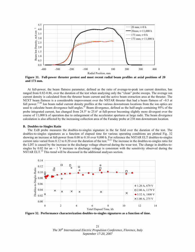
B. Doubles-to-Singles Ratio The ExB probe measures the doubles-to-singles signature in the far field over the duration of the test. The
doubles-to-singles signatures as a function of elapsed time for various operating conditions are plotted Fig. 32 showing an increase at full-power from 0.08 to 0.10 over 9,000 h. For reference the NSTAR ELT doubles-to-singles current ratio varied from 0.12 to 0.20 over the duration of the test.18,21 The increase in the doubles-to-singles ratio for the LDT is caused by the increase in the discharge voltage observed during the wear test. The change in doubles-to-singles by 0.02 for an ~ 1 V increase in discharge voltage is consistent with the sensitivity observed during the NSTAR ELT.18 This trend will be discussed in the additional analyses section.
0.00
0.02
0.04
0.06
0.08
0.10
0.12
0.14
0 2 4 6 8 10 12 14Total Elapsed Time, kh
Dou
bles
-to-S
ingl
es R
atio
.
1.20 A, 679 V2.00 A, 1179 V3.52 A, 1800 V1.00 A, 275 V
Figure 32. Performance characterization doubles-to-singles signatures as a function of time.
0.00.51.01.52.02.53.03.54.04.5
-400 -300 -200 -100 0 100 200 300 400Radial Position, mm
Bea
m Io
n D
ensi
ty, m
A/c
m .
20 mm; t=0 h20mm; t=11,000 h173 mm; t=0 h173 mm; t=11,000 h
2
Figure 31. Full-power thruster pretest and most recent radial beam profiles at axial positions of 20 and 173 mm.
The 30th International Electric Propulsion Conference, Florence, Italy
September 17-20, 2007
22
C. Erosion Results The discharge cathode assembly (DCA), neutralizer cathode assembly (NCA), accelerator grid center-radius
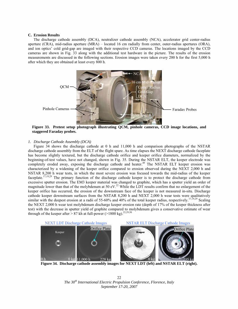
aperture (CRA), mid-radius aperture (MRA) – located 16 cm radially from center, outer-radius apertures (ORA), and ion optics’ cold grid-gap are imaged with their respective CCD cameras. The locations imaged by the CCD cameras are shown in Fig. 33 along with the additional test hardware in the picture. The results of the erosion measurements are discussed in the following sections. Erosion images were taken every 200 h for the first 5,000 h after which they are obtained at least every 800 h.
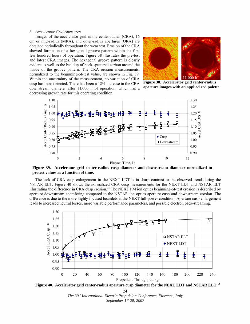
1. Discharge Cathode Assembly (DCA)
Figure 34 shows the discharge cathode at 0 h and 11,000 h and comparison photographs of the NSTAR discharge cathode assembly from the ELT of the flight spare. As time elapses the NEXT discharge cathode faceplate has become slightly textured, but the discharge cathode orifice and keeper orifice diameters, normalized by the beginning-of-test values, have not changed, shown in Fig. 35. During the NSTAR ELT, the keeper electrode was completely eroded away, exposing the discharge cathode and heater.49 The NSTAR ELT keeper erosion was characterized by a widening of the keeper orifice compared to erosion observed during the NEXT 2,000 h and NSTAR 8,200 h wear tests, in which the most severe erosion was focused towards the mid-radius of the keeper faceplate.17,19,29 The primary function of the discharge cathode keeper is to protect the discharge cathode from excessive sputter erosion. The EM3 keeper material was changed to graphite, which has a sputter yield an order of magnitude lower than that of the molybdenum at 50 eV.22 While the LDT results confirm that no enlargement of the keeper orifice has occurred, the erosion of the downstream face of the keeper is not measured in-situ. Discharge cathode keeper downstream surfaces from the NSTAR 8,200 h and NEXT 2,000 h wear tests were qualitatively similar with the deepest erosion at a radii of 55-60% and 40% of the total keeper radius, respectively.17,19,29 Scaling the NEXT 2,000 h wear test molybdenum discharge keeper erosion rate (depth of 17% of the keeper thickness after test) with the decrease in sputter yield of graphite compared to molybdenum gives a conservative estimate of wear through of the keeper after > 87 kh at full-power (>1800 kg).22,29,50
Figure 33. Pretest setup photograph illustrating QCM, pinhole cameras, CCD image locations, and staggered Faraday probes.
Figure 34. Discharge cathode assembly images for NEXT LDT (left) and NSTAR ELT (right).
NCA
16 cm Mid-RadiusCenter RadiusGrid-Gap DCA
Outer Radius
QCM
Pinhole Cameras Faraday Probes
Keeper
0 h 0 kg 11,000 h 228 kg 0 kg 235 kg
NEXT LDT Discharge Cathode Images NSTAR ELT Discharge Cathode Images Orifice Plate Orifice Plate

The 30th International Electric Propulsion Conference, Florence, Italy
September 17-20, 2007
23
2. Neutralizer Cathode Assembly (NCA) Figure 36 shows the neutralizer cathode assembly
(NCA) pretest and latest image taken after 11,000 h of thruster operation. Texturing of the neutralizer cathode faceplate is observed and a darkening of the keeper is seen due to back-sputtered carbon deposition from the facility. The NCA is located in the 12 o’clock position of the thruster so any erosion due to placement of the NCA in the high-energy beam would be seen in the bottom of the images taken, which appears pristine. Normalized measurements from the erosion images, shown in Fig. 37, confirm no observed erosion of the NCA keeper orifice diameter or cathode orifice diameter.
Though the neutralizer orifice does not show any erosion when imaging on centerline, it is likely that EM3 neutralizer orifice channel has a similar erosion profile to the NSTAR 8,200 h wear test and NSTAR ELT.17,18 The image of the orifice is taken looking down the axis of the cathode and thus only will show the smallest diameter along the channel. The reduction in neutralizer flow margin suggests erosion of the orifice channel is occurring.
0.60
0.70
0.80
0.90
1.00
1.10
1.20
0 2 4 6 8 10 12Elapsed Time, kh
NC
A C
atho
de O
rific
e .
0.90
1.00
1.10
1.20
1.30
1.40
1.50N
CA
Kee
per O
rific
e .
Cathode OrificeCathode Orifice ChamferKeeper Orifice
Figure 37. Neutralizer cathode orifice diameter, orifice chamfer diameter, and keeper orifice diameter normalized to pretest values as a function of time.
0.70
0.75
0.80
0.85
0.90
0.95
1.00
1.05
1.10
0 2 4 6 8 10 12Elapsed Time, kh
DC
A C
atho
de O
rific
e .
0.90
0.95
1.00
1.05
1.10
1.15
1.20
1.25
1.30
DC
A K
eepe
r Orif
ice
.
Cathode OrificeCathode Orifice ChamferKeeper Orifice
φ φ
Figure 35. NEXT discharge cathode orifice diameter, orifice chamfer diameter, and keeper orifice diameter normalized to pretest values as a function of time.
Figure 36. Neutralizer assembly erosion images. 0 h 11,000 h
The 30th International Electric Propulsion Conference, Florence, Italy
September 17-20, 2007
24
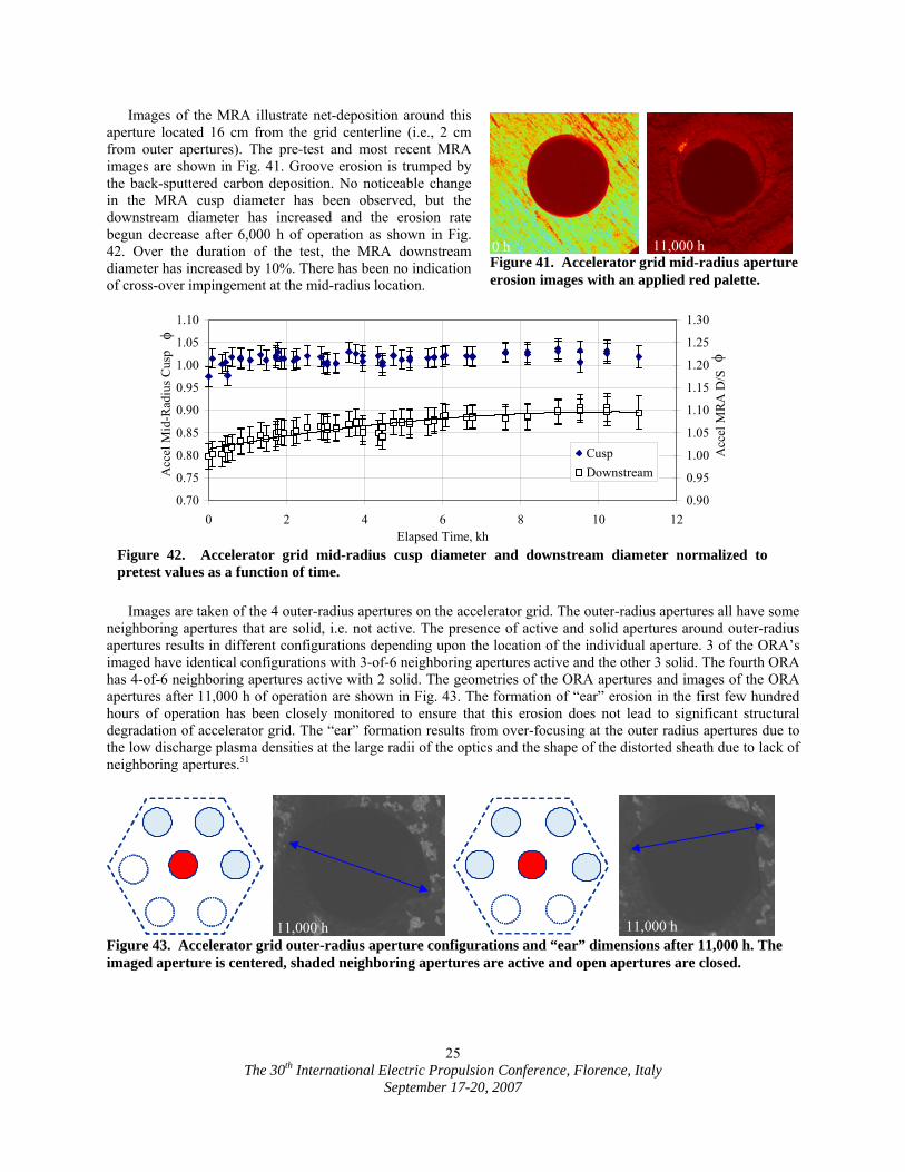
3. Accelerator Grid Apertures Images of the accelerator grid at the center-radius (CRA), 16
cm or mid-radius (MRA), and outer-radius apertures (ORA) are obtained periodically throughout the wear test. Erosion of the CRA showed formation of a hexagonal groove pattern within the first few hundred hours of operation. Figure 38 illustrates the pre-test and latest CRA images. The hexagonal groove pattern is clearly evident as well as the buildup of back-sputtered carbon around the inside of the groove pattern. The CRA erosion measurements, normalized to the beginning-of-test value, are shown in Fig. 39. Within the uncertainty of the measurement, no variation of CRA cusp has been detected. There has been a 12% increase in the CRA downstream diameter after 11,000 h of operation, which has a decreasing growth rate for this operating condition.
The lack of CRA cusp enlargement in the NEXT LDT is in sharp contrast to the observed trend during the NSTAR ELT. Figure 40 shows the normalized CRA cusp measurements for the NEXT LDT and NSTAR ELT illustrating the difference in CRA cusp erosion.18 The NEXT PM ion optics beginning-of-test erosion is described by aperture downstream chamfering compared to the NSTAR ion optics aperture cusp and downstream erosion. The difference is due to the more highly focused beamlets at the NEXT full-power condition. Aperture cusp enlargement leads to increased neutral losses, more variable performance parameters, and possible electron back-streaming.
0.70
0.75
0.80
0.85
0.90
0.95
1.00
1.05
1.10
0 2 4 6 8 10 12Elapsed Time, kh
Acc
el C
ente
r Rad
ius C
usp
.
0.90
0.95
1.00
1.05
1.10
1.15
1.20
1.25
1.30
Acc
el C
RA
D/S
CuspDownstream
φ
φ
Figure 39. Accelerator grid center-radius cusp diameter and downstream diameter normalized to pretest values as a function of time.
0.90
0.95
1.00
1.05
1.10
1.15
1.20
1.25
1.30
0 20 40 60 80 100 120 140 160 180 200 220 240Propellant Throughput, kg
Acc
el C
RA
Cus
p .
NSTAR ELT
NEXT LDT
φ
Figure 40. Accelerator grid center-radius aperture cusp diameter for the NEXT LDT and NSTAR ELT.18
Figure 38. Accelerator grid center-radius aperture images with an applied red palette.
0 h 11,000 h
The 30th International Electric Propulsion Conference, Florence, Italy
September 17-20, 2007
25
Images of the MRA illustrate net-deposition around this aperture located 16 cm from the grid centerline (i.e., 2 cm from outer apertures). The pre-test and most recent MRA images are shown in Fig. 41. Groove erosion is trumped by the back-sputtered carbon deposition. No noticeable change in the MRA cusp diameter has been observed, but the downstream diameter has increased and the erosion rate begun decrease after 6,000 h of operation as shown in Fig. 42. Over the duration of the test, the MRA downstream diameter has increased by 10%. There has been no indication of cross-over impingement at the mid-radius location.
Images are taken of the 4 outer-radius apertures on the accelerator grid. The outer-radius apertures all have some
neighboring apertures that are solid, i.e. not active. The presence of active and solid apertures around outer-radius apertures results in different configurations depending upon the location of the individual aperture. 3 of the ORA’s imaged have identical configurations with 3-of-6 neighboring apertures active and the other 3 solid. The fourth ORA has 4-of-6 neighboring apertures active with 2 solid. The geometries of the ORA apertures and images of the ORA apertures after 11,000 h of operation are shown in Fig. 43. The formation of “ear” erosion in the first few hundred hours of operation has been closely monitored to ensure that this erosion does not lead to significant structural degradation of accelerator grid. The “ear” formation results from over-focusing at the outer radius apertures due to the low discharge plasma densities at the large radii of the optics and the shape of the distorted sheath due to lack of neighboring apertures.51
0.70
0.75
0.80
0.85
0.90
0.95
1.00
1.05
1.10
0 2 4 6 8 10 12Elapsed Time, kh
Acc
el M
id-R
adiu
s Cus
p .
0.90
0.95
1.00
1.05
1.10
1.15
1.20
1.25
1.30
Acc
el M
RA
D/S
.
CuspDownstream
φ
φ
Figure 42. Accelerator grid mid-radius cusp diameter and downstream diameter normalized to pretest values as a function of time.
Figure 43. Accelerator grid outer-radius aperture configurations and “ear” dimensions after 11,000 h. The imaged aperture is centered, shaded neighboring apertures are active and open apertures are closed.
Figure 41. Accelerator grid mid-radius aperture erosion images with an applied red palette.
0 h 11,000 h
11,000 h 11,000 h
The 30th International Electric Propulsion Conference, Florence, Italy
September 17-20, 2007
26
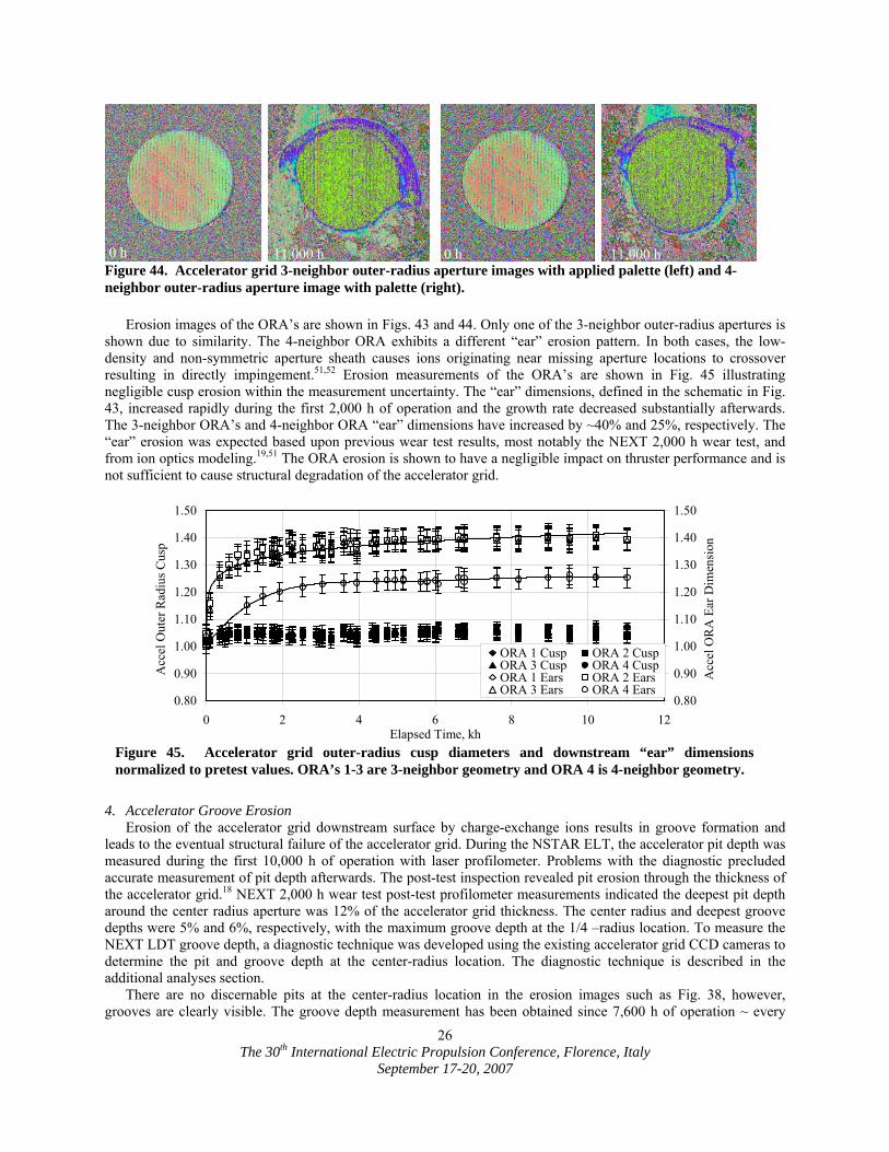
Erosion images of the ORA’s are shown in Figs. 43 and 44. Only one of the 3-neighbor outer-radius apertures is
shown due to similarity. The 4-neighbor ORA exhibits a different “ear” erosion pattern. In both cases, the low-density and non-symmetric aperture sheath causes ions originating near missing aperture locations to crossover resulting in directly impingement.51,52 Erosion measurements of the ORA’s are shown in Fig. 45 illustrating negligible cusp erosion within the measurement uncertainty. The “ear” dimensions, defined in the schematic in Fig. 43, increased rapidly during the first 2,000 h of operation and the growth rate decreased substantially afterwards. The 3-neighbor ORA’s and 4-neighbor ORA “ear” dimensions have increased by ~40% and 25%, respectively. The “ear” erosion was expected based upon previous wear test results, most notably the NEXT 2,000 h wear test, and from ion optics modeling.19,51 The ORA erosion is shown to have a negligible impact on thruster performance and is not sufficient to cause structural degradation of the accelerator grid.
4. Accelerator Groove Erosion
Erosion of the accelerator grid downstream surface by charge-exchange ions results in groove formation and leads to the eventual structural failure of the accelerator grid. During the NSTAR ELT, the accelerator pit depth was measured during the first 10,000 h of operation with laser profilometer. Problems with the diagnostic precluded accurate measurement of pit depth afterwards. The post-test inspection revealed pit erosion through the thickness of the accelerator grid.18 NEXT 2,000 h wear test post-test profilometer measurements indicated the deepest pit depth around the center radius aperture was 12% of the accelerator grid thickness. The center radius and deepest groove depths were 5% and 6%, respectively, with the maximum groove depth at the 1/4 –radius location. To measure the NEXT LDT groove depth, a diagnostic technique was developed using the existing accelerator grid CCD cameras to determine the pit and groove depth at the center-radius location. The diagnostic technique is described in the additional analyses section.
There are no discernable pits at the center-radius location in the erosion images such as Fig. 38, however, grooves are clearly visible. The groove depth measurement has been obtained since 7,600 h of operation ~ every
0.80
0.90
1.00
1.10
1.20
1.30
1.40
1.50
0 2 4 6 8 10 12Elapsed Time, kh
Acc
el O
uter
Rad
ius C
usp
.
0.80
0.90
1.00
1.10
1.20
1.30
1.40
1.50
Acc
el O
RA
Ear
Dim
ensi
on .
ORA 1 Cusp ORA 2 CuspORA 3 Cusp ORA 4 CuspORA 1 Ears ORA 2 EarsORA 3 Ears ORA 4 Ears
Figure 45. Accelerator grid outer-radius cusp diameters and downstream “ear” dimensions normalized to pretest values. ORA’s 1-3 are 3-neighbor geometry and ORA 4 is 4-neighbor geometry.
Figure 44. Accelerator grid 3-neighbor outer-radius aperture images with applied palette (left) and 4-neighbor outer-radius aperture image with palette (right).
0 h 11,000 h 0 h 11,000 h
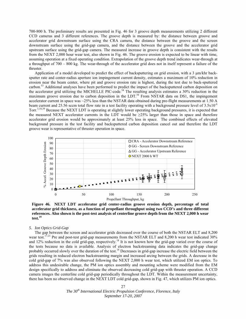
The 30th International Electric Propulsion Conference, Florence, Italy
September 17-20, 2007
27
700-800 h. The preliminary results are presented in Fig. 46 for 3 groove depth measurements utilizing 2 different CCD cameras and 3 different references. The groove depth is measured by: the distance between groove and accelerator grid downstream surface using the CRA camera, the distance between the groove and the screen downstream surface using the grid-gap camera, and the distance between the groove and the accelerator grid upstream surface using the grid-gap camera. The measured increase in groove depth is consistent with the results from the NEXT 2,000 hour wear test, also shown in Fig. 46. The groove erosion is expected to be linear with time, assuming operation at a fixed operating condition. Extrapolation of the groove depth trend indicates wear-through at a throughput of 700 – 800 kg. The wear-through of the accelerator grid does not in itself represent a failure of the thruster.
Application of a model developed to predict the effect of backsputtering on grid erosion, with a 3 µm/khr back-sputter rate and center-radius aperture ion impingement current density, estimates a maximum of 10% reduction in erosion near the beam center, where pit and groove erosion rate is highest, during the test due to back-sputtered carbon.53 Additional analyses have been performed to predict the impact of the backsputtered carbon deposition on the accelerator grid utilizing the MICHELLE PIC-code.54 The resulting analysis estimates a 30% reduction in the maximum groove erosion due to carbon deposition in the LDT.54 From NSTAR data on DS1, the impingement accelerator current in space was ~25% less than the NSTAR data obtained during pre-flight measurements at 1.50 A beam current and 25.56 sccm total flow rate in a test facility operating with a background pressure level of 3.5x10⁻⁶ Torr.3,18,39 Because the NEXT LDT is operating at slightly lower operating background pressures, it is expected that the measured NEXT accelerator currents in the LDT would be ≥25% larger than those in space and therefore accelerator grid erosion would be approximately at least 25% less in space. The combined effects of elevated background pressure in the test facility and backsputtered carbon deposition cancel out and therefore the LDT groove wear is representative of thruster operation in space.
5. Ion Optics Grid-Gap The gap between the screen and accelerator grids decreased over the course of both the NSTAR ELT and 8,200
wear test.17,21 Pre and post-test grid-gap measurements from the NSTAR ELT and 8,200 h wear test indicated 30% and 12% reduction in the cold grid-gap, respectively.18 It is not known how the grid-gap varied over the course of the tests because no data is available. Analysis of electron backstreaming data indicates the grid-gap change probably occurred slowly over the duration of the test.18 Decreases in grid-gap increase the electric field between the grids resulting in reduced electron backstreaming margin and increased arcing between the grids. A decrease in the cold grid-gap of 7% was also observed following the NEXT 2,000 h wear test, which utilized EM ion optics. To address this undesirable change, the PM ion optics assembly and mounting scheme were modified from the EM design specifically to address and eliminate the observed decreasing cold grid-gap with thruster operation. A CCD camera images the centerline cold grid-gap periodically throughout the LDT. Within the measurement uncertainty, there has been no observed change in the NEXT LDT cold grid-gap, shown in Fig. 47, which utilizes PM ion optics.
0102030405060708090
100
0 50 100 150 200 250Propellant Throughput, kg
% A
ccel
. Gro
ove
Dep
th E
rosi
on . CRA - Accelerator Downstream Reference
GG - Screen Downstream ReferenceGG - Accelerator Upstream ReferenceNEXT 2000 h WT
Figure 46. NEXT LDT accelerator grid center-radius groove erosion depth, percentage of total accelerator grid thickness, as a function of propellant throughput using two CCD’s and three different references. Also shown is the post-test analysis of centerline groove depth from the NEXT 2,000 h wear test.19
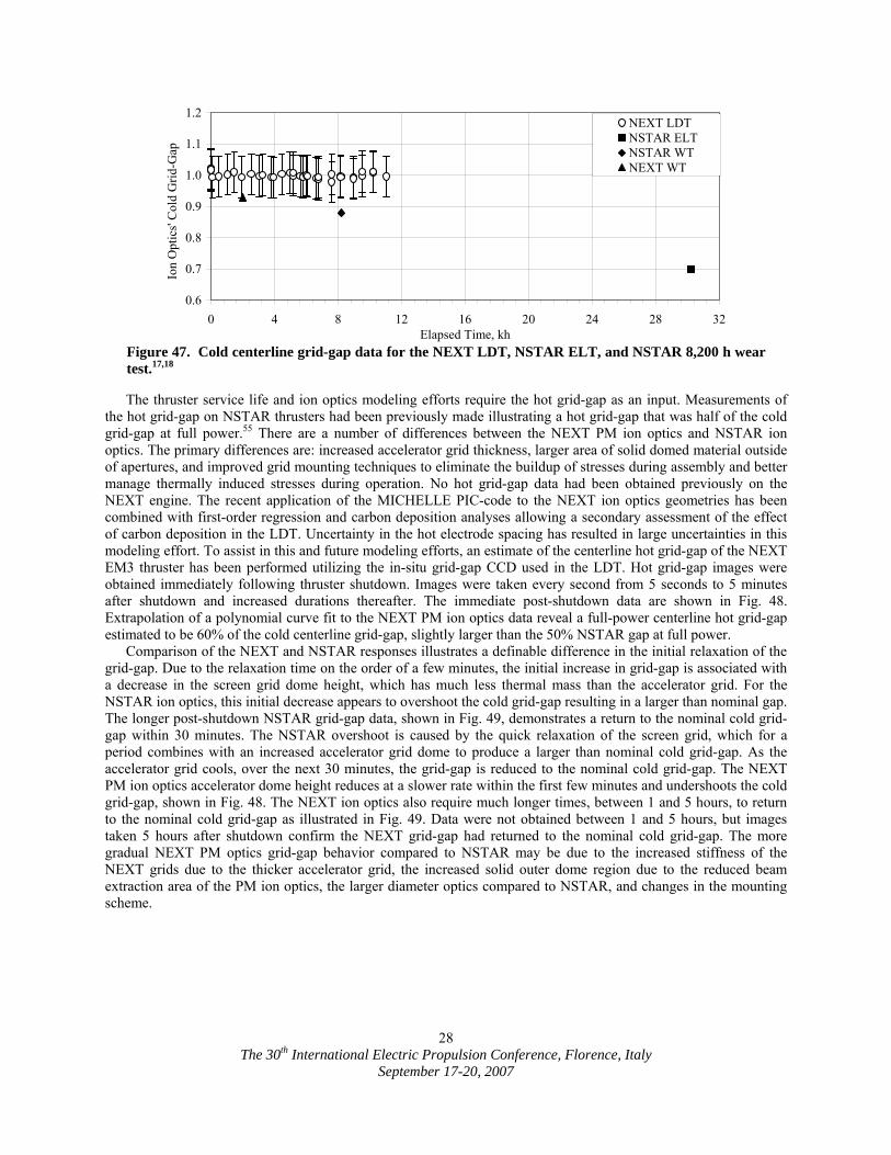
The 30th International Electric Propulsion Conference, Florence, Italy
September 17-20, 2007
28
The thruster service life and ion optics modeling efforts require the hot grid-gap as an input. Measurements of the hot grid-gap on NSTAR thrusters had been previously made illustrating a hot grid-gap that was half of the cold grid-gap at full power.55 There are a number of differences between the NEXT PM ion optics and NSTAR ion optics. The primary differences are: increased accelerator grid thickness, larger area of solid domed material outside of apertures, and improved grid mounting techniques to eliminate the buildup of stresses during assembly and better manage thermally induced stresses during operation. No hot grid-gap data had been obtained previously on the NEXT engine. The recent application of the MICHELLE PIC-code to the NEXT ion optics geometries has been combined with first-order regression and carbon deposition analyses allowing a secondary assessment of the effect of carbon deposition in the LDT. Uncertainty in the hot electrode spacing has resulted in large uncertainties in this modeling effort. To assist in this and future modeling efforts, an estimate of the centerline hot grid-gap of the NEXT EM3 thruster has been performed utilizing the in-situ grid-gap CCD used in the LDT. Hot grid-gap images were obtained immediately following thruster shutdown. Images were taken every second from 5 seconds to 5 minutes after shutdown and increased durations thereafter. The immediate post-shutdown data are shown in Fig. 48. Extrapolation of a polynomial curve fit to the NEXT PM ion optics data reveal a full-power centerline hot grid-gap estimated to be 60% of the cold centerline grid-gap, slightly larger than the 50% NSTAR gap at full power.
Comparison of the NEXT and NSTAR responses illustrates a definable difference in the initial relaxation of the grid-gap. Due to the relaxation time on the order of a few minutes, the initial increase in grid-gap is associated with a decrease in the screen grid dome height, which has much less thermal mass than the accelerator grid. For the NSTAR ion optics, this initial decrease appears to overshoot the cold grid-gap resulting in a larger than nominal gap. The longer post-shutdown NSTAR grid-gap data, shown in Fig. 49, demonstrates a return to the nominal cold grid-gap within 30 minutes. The NSTAR overshoot is caused by the quick relaxation of the screen grid, which for a period combines with an increased accelerator grid dome to produce a larger than nominal cold grid-gap. As the accelerator grid cools, over the next 30 minutes, the grid-gap is reduced to the nominal cold grid-gap. The NEXT PM ion optics accelerator dome height reduces at a slower rate within the first few minutes and undershoots the cold grid-gap, shown in Fig. 48. The NEXT ion optics also require much longer times, between 1 and 5 hours, to return to the nominal cold grid-gap as illustrated in Fig. 49. Data were not obtained between 1 and 5 hours, but images taken 5 hours after shutdown confirm the NEXT grid-gap had returned to the nominal cold grid-gap. The more gradual NEXT PM optics grid-gap behavior compared to NSTAR may be due to the increased stiffness of the NEXT grids due to the thicker accelerator grid, the increased solid outer dome region due to the reduced beam extraction area of the PM ion optics, the larger diameter optics compared to NSTAR, and changes in the mounting scheme.
0.6
0.7
0.8
0.9
1.0
1.1
1.2
0 4 8 12 16 20 24 28 32Elapsed Time, kh
Ion
Opt
ics'
Col
d G
rid-G
ap .
NEXT LDTNSTAR ELTNSTAR WTNEXT WT
Figure 47. Cold centerline grid-gap data for the NEXT LDT, NSTAR ELT, and NSTAR 8,200 h wear test.17,18
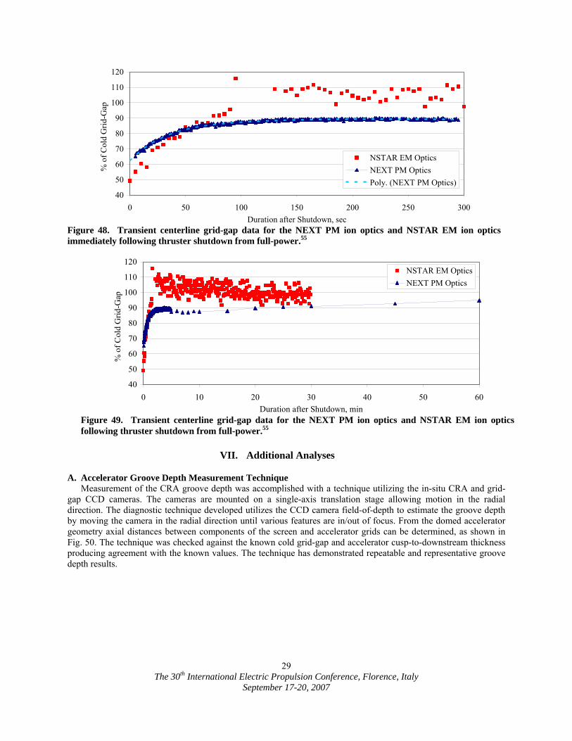
The 30th International Electric Propulsion Conference, Florence, Italy
September 17-20, 2007
29
VII. Additional Analyses
A. Accelerator Groove Depth Measurement Technique Measurement of the CRA groove depth was accomplished with a technique utilizing the in-situ CRA and grid-
gap CCD cameras. The cameras are mounted on a single-axis translation stage allowing motion in the radial direction. The diagnostic technique developed utilizes the CCD camera field-of-depth to estimate the groove depth by moving the camera in the radial direction until various features are in/out of focus. From the domed accelerator geometry axial distances between components of the screen and accelerator grids can be determined, as shown in Fig. 50. The technique was checked against the known cold grid-gap and accelerator cusp-to-downstream thickness producing agreement with the known values. The technique has demonstrated repeatable and representative groove depth results.
40
50
60
70
80
90
100
110
120
0 10 20 30 40 50 60Duration after Shutdown, min
% o
f Col
d G
rid-G
ap .
NSTAR EM OpticsNEXT PM Optics
Figure 49. Transient centerline grid-gap data for the NEXT PM ion optics and NSTAR EM ion opticsfollowing thruster shutdown from full-power.55
40
50
60
70
80
90
100
110
120
0 50 100 150 200 250 300Duration after Shutdown, sec
% o
f Col
d G
rid-G
ap .
NSTAR EM OpticsNEXT PM OpticsPoly. (NEXT PM Optics)
Figure 48. Transient centerline grid-gap data for the NEXT PM ion optics and NSTAR EM ion opticsimmediately following thruster shutdown from full-power.55
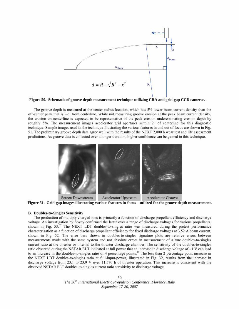
The 30th International Electric Propulsion Conference, Florence, Italy
September 17-20, 2007
30
The groove depth is measured at the center-radius location, which has 5% lower beam current density than the
off-center peak that is ~2” from centerline. While not measuring groove erosion at the peak beam current density, the erosion on centerline is expected to be representative of the peak erosion underestimating erosion depth by roughly 5%. The measurement images accelerator grid apertures within 2” of centerline for this diagnostic technique. Sample images used in the technique illustrating the various features in and out of focus are shown in Fig. 51. The preliminary groove depth data agree well with the results of the NEXT 2,000 h wear test and life assessment predictions. As groove data is collected over a longer duration, higher confidence can be gained in this technique.
B. Doubles-to-Singles Sensitivity The production of multiply charged ions is primarily a function of discharge propellant efficiency and discharge
voltage. An investigation by Sovey confirmed the latter over a range of discharge voltages for various propellants, shown in Fig. 53.37 The NEXT LDT doubles-to-singles ratio was measured during the pretest performance characterization as a function of discharge propellant efficiency for fixed discharge voltages at 3.52 A beam current, shown in Fig. 52. The error bars shown in doubles-to-singles signature plots are relative errors between measurements made with the same system and not absolute errors in measurement of a true doubles-to-singles current ratio at the thruster or internal to the thruster discharge chamber. The sensitivity of the doubles-to-singles ratio observed during the NSTAR ELT indicated at full power that an increase in discharge voltage of ~1 V can lead to an increase in the doubles-to-singles ratio of 4 percentage points.18 The less than 2 percentage point increase in the NEXT LDT doubles-to-singles ratio at full-input-power, illustrated in Fig. 32, results from the increase in discharge voltage from 23.1 to 23.9 V over 11,570 h of thruster operation. This increase is consistent with the observed NSTAR ELT doubles-to-singles current ratio sensitivity to discharge voltage.
R
wDome
dDome
xd
22 xRRd −−=
Figure 50. Schematic of groove depth measurement technique utilizing CRA and grid-gap CCD cameras.
Figure 51. Grid-gap images illustrating various features in-focus – utilized for the groove depth measurement.
Screen Downstream Accelerator Upstream Accelerator Groove
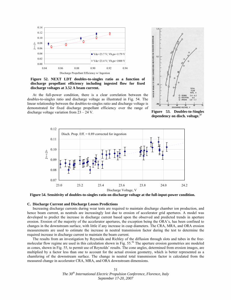
The 30th International Electric Propulsion Conference, Florence, Italy
September 17-20, 2007
31
At the full-power condition, there is a clear correlation between the
doubles-to-singles ratio and discharge voltage as illustrated in Fig. 54. The linear relationship between the doubles-to-singles ratio and discharge voltage is demonstrated for fixed discharge propellant efficiency over the range of discharge voltage variation from 23 – 24 V.
C. Discharge Current and Discharge Losses Predictions Increasing discharge currents during wear tests are required to maintain discharge chamber ion production, and
hence beam current, as neutrals are increasingly lost due to erosion of accelerator grid apertures. A model was developed to predict the increase in discharge current based upon the observed and predicted trends in aperture erosion. Erosion of the majority of the accelerator apertures, the exception being the ORA’s, has been confined to changes in the downstream surface, with little if any increase in cusp diameters. The CRA, MRA, and ORA erosion measurements are used to estimate the increase in neutral transmission factor during the test to determine the required increase in discharge current to maintain the beam current.
The results from an investigation by Reynolds and Richley of the diffusion through slots and tubes in the free-molecular flow regime are used in this calculation shown in Fig. 55.56 The aperture erosion geometries are modeled as cones, shown in Fig. 55, to permit use of Reynolds’ results. The cone angles, determined from erosion images, are multiplied by a factor less than one to account for the actual erosion geometry, which is better represented as a chamfering of the downstream surface. The change in neutral total transmission factor is calculated from the measured change in accelerator CRA, MRA, and ORA downstream dimensions.
0.07
0.08
0.09
0.10
0.11
0.12
23.0 23.2 23.4 23.6 23.8 24.0 24.2Discharge Voltage, V
J++/
J+
Disch. Prop. Eff. = 0.89 corrected for ingestion
Figure 54. Sensitivity of doubles-to-singles ratio on discharge voltage at the full-input-power condition.
Figure 53. Doubles-to-Singlesdependency on disch. voltage.37
0.00
0.02
0.04
0.06
0.08
0.10
0.12
0.14
0.84 0.86 0.88 0.90 0.92 0.94
Discharge Propellant Efficiency w/ Ingestion
J++/
J+
Vdc=23.7 V; Vb,ps=1179 V
Vdc=23.4 V; Vb,ps=1800 V
Figure 52. NEXT LDT doubles-to-singles ratio as a function of discharge propellant efficiency including ingested flow for fixed discharge voltages at 3.52 A beam current.
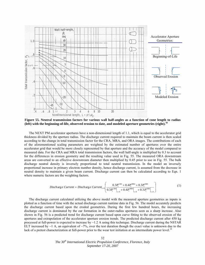
The 30th International Electric Propulsion Conference, Florence, Italy
September 17-20, 2007
32
The NEXT PM accelerator apertures have a non-dimensional length of 1.1, which is equal to the accelerator grid
thickness divided by the aperture radius. The discharge current required to maintain the beam current is then scaled according to the change in total transmission factor for the CRA, MRA, and ORA images. The contributions of each of the aforementioned scaling parameters are weighted by the estimated number of apertures over the entire accelerator grid that would be more closely represented by that aperture and the accuracy of the model compared to measured data. For the CRA and MRA total transmission factors, the wall half-angle is multiplied by 0.3 to account for the differences in erosion geometry and the resulting value used in Fig. 55. The measured ORA downstream areas are converted to an effective downstream diameter then multiplied by 0.45 prior to use in Fig. 55. The bulk discharge neutral density is inversely proportional to total neutral transmission. In the model an inversely proportional increase in primary electron number density, hence discharge current, is assumed from the decrease in neutral density to maintain a given beam current. Discharge current can then be calculated according to Eqn. 1 where numeric factors are the weighting factors.
⎟⎟
⎠
⎞
⎜⎜
⎝
⎛
++++
====
=
000
0 3.04.03.03.04.03.0argarg
t
ORAtt
MRAtt
CRAt
ORAt
MRAt
CRAt
t PPPPPPCurrenteDischCurrenteDisch (1)
The discharge current calculated utilizing the above model with the measured aperture geometries as inputs is plotted as a function of time with the actual discharge current runtime data in Fig. 56. The model accurately predicts the discharge current based upon the eroded geometries. During the first few hundred hours, the increasing discharge current is dominated by the ear formation in the outer-radius apertures seen as a sharp increase. Also shown in Fig. 56 is a predicted trend for discharge current based upon curve fitting to the observed erosion of the apertures and extrapolation of the accelerator aperture erosion trends. The predicted discharge current after 450 kg processed at full-power is expected to increase by ~1.2 A using this technique. Discharge current during the NSTAR ELT increased by ~1 A, an equivalent of ~7%, over the test duration though the exact value is unknown due to the lack of a pretest characterization at full-power prior to the wear test initiation at an intermediate power level.18
Figure 55. Neutral transmission factors for various wall half-angles as a function of cone length to radius(left) with the beginning-of-life, observed erosion to date, and modeled aperture geometries (right).56
β
Beginning-of-Life
Observed Erosion
Modeled Erosion
Accelerator Aperture Geometries:
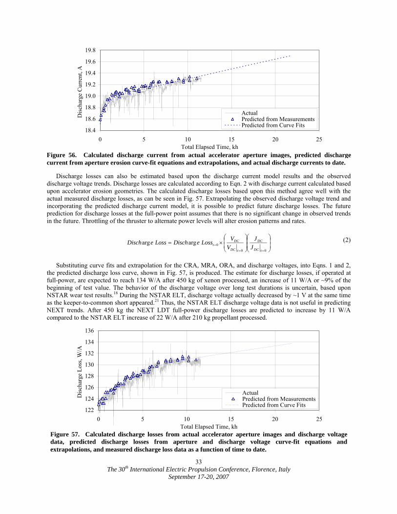
The 30th International Electric Propulsion Conference, Florence, Italy
September 17-20, 2007
33
Discharge losses can also be estimated based upon the discharge current model results and the observed
discharge voltage trends. Discharge losses are calculated according to Eqn. 2 with discharge current calculated based upon accelerator erosion geometries. The calculated discharge losses based upon this method agree well with the actual measured discharge losses, as can be seen in Fig. 57. Extrapolating the observed discharge voltage trend and incorporating the predicted discharge current model, it is possible to predict future discharge losses. The future prediction for discharge losses at the full-power point assumes that there is no significant change in observed trends in the future. Throttling of the thruster to alternate power levels will alter erosion patterns and rates.
⎟⎟⎠
⎞⎜⎜⎝
⎛⎟⎟⎠
⎞⎜⎜⎝
⎛×=
==
=
000argarg
tDC
DC
tDC
DCt J
JV
VLosseDischLosseDisch (2)
Substituting curve fits and extrapolation for the CRA, MRA, ORA, and discharge voltages, into Eqns. 1 and 2, the predicted discharge loss curve, shown in Fig. 57, is produced. The estimate for discharge losses, if operated at full-power, are expected to reach 134 W/A after 450 kg of xenon processed, an increase of 11 W/A or ~9% of the beginning of test value. The behavior of the discharge voltage over long test durations is uncertain, based upon NSTAR wear test results.18 During the NSTAR ELT, discharge voltage actually decreased by ~1 V at the same time as the keeper-to-common short appeared.21 Thus, the NSTAR ELT discharge voltage data is not useful in predicting NEXT trends. After 450 kg the NEXT LDT full-power discharge losses are predicted to increase by 11 W/A compared to the NSTAR ELT increase of 22 W/A after 210 kg propellant processed.
18.4
18.6
18.8
19.0
19.2
19.4
19.6
19.8
0 5 10 15 20 25Total Elapsed Time, kh
Dis
char
ge C
urre
nt, A
.
ActualPredicted from MeasurementsPredicted from Curve Fits
Figure 56. Calculated discharge current from actual accelerator aperture images, predicted discharge current from aperture erosion curve-fit equations and extrapolations, and actual discharge currents to date.
122
124
126
128
130
132
134
136
0 5 10 15 20 25Total Elapsed Time, kh
Dis
char
ge L
oss,
W/A
.
ActualPredicted from MeasurementsPredicted from Curve Fits
Figure 57. Calculated discharge losses from actual accelerator aperture images and discharge voltage data, predicted discharge losses from aperture and discharge voltage curve-fit equations and extrapolations, and measured discharge loss data as a function of time to date.
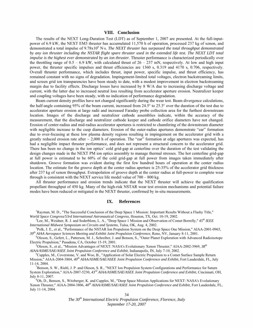
The 30th International Electric Propulsion Conference, Florence, Italy
September 17-20, 2007
34
VIII. Conclusion The results of the NEXT Long-Duration Test (LDT) as of September 1, 2007 are presented. At the full-input-
power of 6.9 kW, the NEXT EM3 thruster has accumulated 11,570 h of operation, processed 237 kg of xenon, and demonstrated a total impulse of 9.78x10⁶ N·s. The NEXT thruster has surpassed the total throughput demonstrated by any ion thruster including the NSTAR flight spare thruster used in the extended life test. The NEXT LDT total impulse is the highest ever demonstrated by an ion thruster. Thruster performance is characterized periodically over the throttling range of 0.5 – 6.9 kW, with calculated thrust of 26 – 237 mN, respectively. At low and high input power, the thruster specific impulses and thrust efficiencies are 1360 s, 0.319 and 4170 s, 0.706, respectively. Overall thruster performance, which includes thrust, input power, specific impulse, and thrust efficiency, has remained constant with no signs of degradation. Impingement-limited total voltages, electron backstreaming limits, and screen grid ion transparencies have been steady to date, with a modest improvement in electron backstreaming margin due to facility effects. Discharge losses have increased by 8 W/A due to increasing discharge voltage and current, with the latter due to increased neutral loss resulting from accelerator aperture erosion. Neutralizer keeper and coupling voltages have been steady, with no indication of performance degradation.
Beam current density profiles have not changed significantly during the wear test. Beam divergence calculations, the half-angle containing 95% of the beam current, increased from 24.5° to 25.3° over the duration of the test due to accelerator aperture erosion at large radii and increased Faraday probe collection area for the furthest downstream location. Images of the discharge and neutralizer cathode assemblies indicate, within the accuracy of the measurement, that the discharge and neutralizer cathode keeper and cathode orifice diameters have not changed. Erosion of center-radius and mid-radius accelerator apertures is restricted to chamfering of the downstream diameter with negligible increase to the cusp diameters. Erosion of the outer-radius apertures demonstrate “ear” formation due to over-focusing at these low plasma density regions resulting in impingement on the accelerator grid with a greatly reduced erosion rate after ~ 2,000 h of operation. The “ear” formation at edge apertures was expected, has had a negligible impact thruster performance, and does not represent a structural concern to the accelerator grid. There has been no change in the ion optics’ cold grid-gap at centerline over the duration of the test validating the design changes made in the NEXT PM ion optics assembly to manage thermal stresses. The hot centerline grid-gap at full power is estimated to be 60% of the cold grid-gap at full power from images taken immediately after shutdown. Groove formation was evident during the first few hundred hours of operation at the center radius location. The estimate for the groove depth at the center radius aperture is 25-35% of the accelerator grid thickness after 237 kg of xenon throughput. Extrapolation of groove depth at the center radius at full-power to complete wear through is consistent with the NEXT service life model value of 700 – 800 kg.
All thruster performance and erosion trends indicate that the NEXT thruster will achieve the qualification propellant throughput of 450 kg. Many of the high-risk NSTAR wear test erosion mechanisms and potential failure modes have been reduced or mitigated in the NEXT thruster, confirmed by in-situ measurements.
IX. References
1Rayman, M. D., "The Successful Conclusion of the Deep Space 1 Mission: Important Results Without a Flashy Title," World Space Congress/53rd International Astronautical Congress, Houston, TX, Oct. 10-19, 2002. 2Lee, M., Weidner, R. J. and Soderblom, L. A., "Deep Space 1 Mission and Observation of Comet Borrelly," 45th IEEE International Midwest Symposium on Circuits and Systems, Tulsa, OK, Aug. 4, 2002. 3Polk, J. E., et al., "Performance of the NSTAR Ion Propulsion System on the Deep Space One Mission," AIAA-2001-0965, 39th AIAA Aerospace Sciences Meeting and Exhibit Joint Propulsion Conference, Reno, NV, January 8-11, 2001. 4Oleson, S., Gefert, L., Patterson, M. J., Schreiber, J. and Benson, S., "Outer Planet Exploration with Advanced Radioisotope Electric Propulsion," Pasadena, CA, October 15-19, 2001. 5Oleson, S., et al., "Mission Advantages of NEXT: NASA's Evolutionary Xenon Thruster," AIAA-2002-3969, 38th AIAA/ASME/SAE/ASEE Joint Propulsion Conference and Exhibit, Indianapolis, IN, July 7-10, 2002. 6Cupples, M., Coverstone, V. and Woo, B., "Application of Solar Electric Propulsion to a Comet Surface Sample Return Mission," AIAA-2004-3804, 40th AIAA/ASME/SAE/ASEE Joint Propulsion Conference and Exhibit, Fort Lauderdale, FL, July 11-14, 2004. 7Benson, S. W., Riehl, J. P. and Oleson, S. R., "NEXT Ion Propulsion System Configurations and Performance for Saturn System Exploration," AIAA-2007-5230, 43rd AIAA/ASME/SAE/ASEE Joint Propulsion Conference and Exhibit, Cincinnati, OH, July 8-11, 2007. 8Oh, D., Benson, S., Witzberger, K. and Cupples, M., "Deep Space Mission Applications for NEXT: NASA's Evolutionary Xenon Thruster," AIAA-2004-3806, 40th AIAA/ASME/SAE/ASEE Joint Propulsion Conference and Exhibit, Fort Lauderdale, FL, July 11-14, 2004.
The 30th International Electric Propulsion Conference, Florence, Italy
September 17-20, 2007
35
9Herman, D. A., Soulas, G. C. and Patterson, M. J., "Performance Evaluation of the Prototype-Model NEXT Ion Thruster," AIAA-2007-5212, 43rd AIAA/ASME/SAE/ASEE Joint Propulsion Conference and Exhibit, Cincinnati, OH, July 8-11, 2007. 10Pinero, L. R., Todd, P. and Hopson, M., "Integration and Qualification of the NEXT Power Processing Unit," AIAA-2007-5214, 43rd AIAA/ASME/SAE/ASEE Joint Propulsion Conference and Exhibit, Cincinnati, OH, July 8-11, 2007. 11Patterson, M. J. and Benson, S. W., "NEXT Ion Propulsion System Development Status and Capabilities," Proceedings, 2007 NASA Science Technology Conference, College Park, MD, June 19 - 21, 2007. 12Snyder, J. S., et al., "Vibration Test of a Breadboard Gimbal for the NEXT Ion Engine," AIAA-2006-4665, 42nd AIAA/ASME/SAE/ASEE Joint Propulsion Conference and Exhibit, Sacramento, CA, July 9-12, 2006. 13Aadland, R. S., Monheiser, J., A., D. E., Wilson, F. C. and Benson, S. W., "Development Status of the NEXT Propellant Management System," AIAA-2004-3974, 40th AIAA/ASME/SAE/ASEE Joint Propulsion Conference and Exhibit, Fort Lauderdale, FL, July 11-14, 2004. 14Hoskins, W. A., et al., "Development of a Prototype Model Ion Thruster for the NEXT System," AIAA-2004-4111, 40th AIAA/ASME/SAE/ASEE Joint Propulsion Conference and Exhibit, Fort Lauderdale, FL, July 11-14, 2004. 15Monheiser, J., Aadland, R. S. and Wilson, F., "Development of a Ground Based Digital Control Interface Unit (DCIU) for the NEXT Propulsion System," AIAA-2004-4112, 40th AIAA/ASME/SAE/ASEE Joint Propulsion Conference and Exhibit, Fort Lauderdale, FL, July 11-14, 2004. 16Van Noord, J. L. and Williams, G. J., "Lifetime Assessment of the NEXT Ion Thruster," AIAA-2007-5274, 43rd AIAA/ASME/SAE/ASEE Joint Propulsion Conference and Exhibit, Cincinnati, OH, July 8-11, 2007. 17Polk, J. E., et al., "An Overview of the Results from an 8200 Hour Wear Test of the NSTAR Ion Thruster," AIAA-1999-2446, 35th AIAA/ASME/SAE/ASEE Joint Propulsion Conference and Exhibit, Los Angeles, CA, June 20-24, 1999. 18Sengupta, A., et al., "The 30,000-Hour Extended-Life Test of the Deep Space 1 Flight Spare Ion Thruster," NASA/TP 2004-213391, The Jet Propulsion Laboratory and NASA Glenn Research Center, Pasadena, March, 2005. 19Soulas, G. C., Kamhawi, H., Patterson, M. J., Britton, M. A. and Frandina, M. M., "NEXT Ion Engine 2000 Hour Wear Test Results," AIAA-2004-3791, 40th AIAA/ASME/SAE/ASEE Joint Propulsion Conference and Exhibit, Fort Lauderdale, FL, July 11-14, 2004. 20Polk, J. E., et al., "A 1000 Hour Wear Test of the NASA NSTAR Ion Thruster," AIAA-1996-2784, 32nd AIAA/ASME/SAE/ASEE Joint Propulsion Conference and Exhibit, Lake Buena Vista, FL, July 1-3, 1996. 21Sengupta, A., et al., "An Overview of the Results from the 30,000 Hr Life Test of Deep Space 1 Flight Spare Engine," AIAA-2004-3608, 40th AIAA/ASME/SAE/ASEE Joint Propulsion Conference and Exhibit, Fort Lauderdale, FL, July 11-14, 2004. 22Doerner, R. P., Whyte, D. G. and Goebel, D. M., "Sputtering Yield Measurements during Low Energy Xenon Plasma Bombardment," Journal of Applied Physics, Vol. 93, No. 9, pp. 5816-5823, May 1. 23Sovey, J., Dever, J. A. and Power, J. L., "Retention of Sputtered Molybdenum on Ion Engine Discharge Chamber Surfaces," IEPC Paper 2001-086, 27th International Electric Propulsion Conference, Pasadena, CA, Oct. 15 - 19, 2001. 24Patterson, M. J. and Benson, S. W., "NEXT Ion Propulsion System Development Status and Performance," AIAA-2007-5199, 43rd AIAA/ASME/SAE/ASEE Joint Propulsion Conference and Exhibit, Cincinnati, OH, July 8-11, 2007. 25Soulas, G. C. and Patterson, M. J., "NEXT Ion Thruster Performance Dispersion Analyses," AIAA-2007-5213, 43rd AIAA/ASME/SAE/ASEE Joint Propulsion Conference and Exhibit, Cincinnati, OH, July 8-11, 2007. 26Soulas, G. C., Domonkos, M. T. and Patterson, M. J., "Performance Evaluation of the NEXT Ion Engine," AIAA-2003-5278, 39th AIAA/ASME/SAE/ASEE Joint Propulsion Conference and Exhibit, Huntsville, AL, July 20-23, 2003. 27Patterson, M. J., Foster, J. E., Haag, T. W., Rawlin, V. K. and Soulas, G. C., "NEXT: NASA's Evolutionary Xenon Thruster," AIAA-2002-3832, 38th AIAA/ASME/SAE/ASEE Joint Propulsion Conference and Exhibit, Indianapolis, IN, July 7-10, 2002. 28Frandina, M. M., Arrington, L. A., Soulas, G. C., Hickman, T. A. and Patterson, M., "Status of the NEXT Ion Thruster Long Duration Test," AIAA-2005-4065, 41st AIAA/ASME/SAE/ASEE Joint Propulsion Conference and Exhibit, Tucson, AZ, July 10-13, 2005. 29Kamhawi, H., Soulas, G. C. and Patterson, M., "NEXT Ion Engine 2000 hour Wear Test Plume and Erosion Results," AIAA-2004-3792, 40th AIAA/ASME/SAE/ASEE Joint Propulsion Conference and Exhibit, Fort Lauderdale, FL, July 11-14, 2004. 30Hickman, T. A., Arrington, L. A., Frandina, M. M. and Soulas, G. C., "Overview of the Diagnostics for the NEXT Long Duration Test," AIAA-2005-4064, 41st AIAA/ASME/SAE/ASEE Joint Propulsion Conference and Exhibit, Tucson, AZ, July 10-13, 2005. 31Pinero, L. R., Patterson, M. J. and Satterwhite, V. E., "Power Console Development for NASA's Electric Propulsion Outreach Program," IEPC Paper 93-250, 23rd International Electric Propulsion Conference, Seattle, WA, Sept. 13-16, 1993. 32Snyder, J. S., Kamhawi, H., Patterson, M. J. and Britton, M., "Single-String Integration Test Measurements of the NEXT Ion Engine Plume," AIAA-2004-3790 and NASA/TM-2005-213196, 40th AIAA/ASME/SAE/ASEE Joint Propulsion Conference and Exhibit, Fort Lauderdale, FL, July 11-14, 2004. 33Brophy, J. R., et al., "The Ion Propulsion System for Dawn," AIAA-2003-4542, 39th AIAA/ASME/SAE/ASEE Joint Propulsion Conference and Exhibit, Huntsville, AL, July 20-23, 2003. 34Brophy, J. R., et al., "Status of the Dawn Ion Propulsion System," AIAA-2004-3433, 40th AIAA/ASME/SAE/ASEE Joint Propulsion Conference and Exhibit, Fort Lauderdale, FL, July 11-14, 2004. 35Myers, R. M., "Proceedings of the Nuclear Electric Propulsion Workshop, Volume 1: Introductory Material and Thruster Concepts, Section: "MPD Thruster Technology"," JPL D-9512 Vol. 1, June 19-22, 1990.
The 30th International Electric Propulsion Conference, Florence, Italy
September 17-20, 2007
36
36Patterson, M. J., Haag, T. W. and Hovan, S. A., "Performance of the NASA 30 cm Ion thruster," IEPC Paper 93-108, 23rd International Electric Propulsion Conference, Seattle, WA, Sept. 13-16, 1993. 37Sovey, J. S., "Improved Ion Containment using a Ring-Cusp Ion Thruster," Journal of Spacecraft and Rockets, Vol. 21, No. 5, pp. 488-495, Sept. - Oct. 1984. 38Stueber, T. and Soulas, G. C., "Electrostatic Ion Thruster Diagnostic Uncertainty Analysis," NASA TP-2007-214665, (to be published). 39Anderson, J. R., et al., "Results of an On-going Long Duration Ground Test of the DS1 Flight Spare Ion Engine," AIAA-1999-2857, 35th AIAA/ASME/SAE/ASEE Joint Propulsion Conference and Exhibit, Los Angeles, CA, June 20-24, 1999. 40Anderson, J. R., Goodfellow, K., Polk, J. E., Rawlin, V. K. and Sovey, J. S., "Performance Characteristics of the NSTAR Ion Thruster During an On-Going Long Duration Ground Test," 2000 IEEE Aerospace Conference Proceedings, Vol. 4, pp. 123-148, March 2000. 41Soulas, G. C., Domonkos, M. T., Kamhawi, H. and Gardner, M. M., "Status of the NEXT Ion Engine Wear Test," AIAA-2003-4863, 39th AIAA/ASME/SAE/ASEE Joint Propulsion Conference and Exhibit, Huntsville, AL, Jul 20-23, 2003. 42Soulas, G. C., Foster, J. E. and Patterson, M. J., "Performance of Titanium Optics on a NASA 30 cm Ion Thruster," AIAA-2000-3814, 36th AIAA/ASME/SAE/ASEE Joint Propulsion Conference and Exhibit, Huntsville, AL, July 16-19, 2000. 43Hanna, J., et al., "Carbon Film Deposition and Flaking Studies in Ion Thruster Environments," AIAA-2005-3524, 41st AIAA/ASME/SAE/ASEE Joint Propulsion Conference and Exhibit, Tucson, AZ, July 10 - 13, 2005. 44Shigeki, T., Yasuyuki, S., Reizo, K., Shigeki, H. and Shigeru, U., "Humidity Dependence of Microwear Characteristics of Amorphous Carbon Films on Silicon Substrates," International Journal on the Science and Technology of Friction, Lubrication, and Wear, Vol. 254, pp. 1042-1049, 2003. 45Klages, C. P., et al., "Deposition and Properties of Carbon-Based Amorphous Protective Coatings," Surface and Coating Technology, Vol. 80, No. 1-2, pp. 121-128, March 1, 1996. 46Soulas, G. C., "Performance Evaluation of Titanium Ion Optics for the NSA 30 cm Ion Thruster," IEPC-01-092, 27th International Electric Propulsion Conference, Pasadena, CA, October 15-19, 2001. 47Soulas, G. C., Haag, T. W. and Patterson, M. J., "Performance Evaluation of 40cm Ion Optics for the NEXT Ion Engine," AIAA-2002-3834, 38th AIAA/ASME/SAE/ASEE Joint Propulsion Conference and Exhibit, Indianapolis, IN, July 7-10, 2002. 48Christensen, J. A., et al., "Design and Fabrication of a Flight Model 2.3 kW Ion Thruster for the Deep Space 1 Mission," AIAA-1998-3327, 34th AIAA/ASME/SAE/ASEE Joint Propulsion Conference and Exhibit, 1998. 49Sengupta, A., Brophy, J. R. and Goodfellow, K. D., "Status of the Extended Life Test of the Deep Space 1 Flight Spare Ion Engine after 30,352 Hours of Operation," AIAA-2003-4558, 39th AIAA/ASME/SAE/ASEE Joint Propulsion Conference and Exhibit, Huntsville, AL, July 20-23, 2003. 50Doerner, R. P. and Goebel, D. M., "Sputtering Yields of Ion Thruster Grid and Cathode Materials during Very Low Xenon Plasma Bombardment," AIAA-2003-4561, 39th JPC, Huntsville, AL, July 20-23. 51Malone, S. P., "Investigation of NEXT Ion Optics Erosion Processes using Computational Modeling," 2005-0356DV, NASA Glenn Research Center, Cleveland, OH, October 20, 2005. 52Malone, S. P. and Soulas, G. C., "Computational Ion Optics Design Evaluations," AIAA-2004-3784, 40th AIAA/ASME/SAE/ASEE Joint Propulsion Conference and Exhibit, Fort Lauderdale, FL, July 11-14, 2004. 53Polk, J. E., Duchemin, O. B., Ho, C. and Koel, B. E., "The Effect of Carbon Deposition on Accelerator Grid Wear Rates in Ion Engine Ground Testing," AIAA-2000-3662, 36th AIAA/ASME/SAE/ASEE Joint Propulsion Conference and Exhibit, Huntsville, AL, July 17-19, 2000. 54Williams, G. J. and Gilland, J. H., "Modeling of the Accelerator Grid Erosion of the NASA Evolutionary Xenon Thruster (NEXT)," IEPC-2007-375, 30th International Electric Propulsion Conference, Florence, Italy, Sept. 17-20, 2007. 55Diaz, E. and Soulas, G. C., "Grid Gap Measurement for an NSTAR Ion Thruster," IEPC-2005-244, 29th International Electric Propulsion Conference, Princeton, NJ, Oct. 31 - Nov. 4, 2005. 56Reynolds, T. W. and Richley, E., "Free-Molecule Flow and Surface Diffusion Through Slots and Tubes - A Summary," NASA TR-R-255, April, 1967.
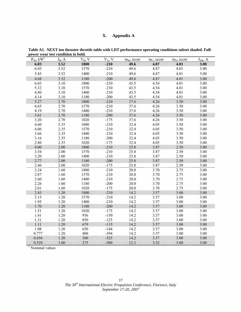
The 30th International Electric Propulsion Conference, Florence, Italy
September 17-20, 2007
37
X. Appendix A Table A1. NEXT ion thruster throttle table with LDT performance operating conditions subset shaded. Full-power wear test condition in bold.
PIN, kW† JB, A VB, V VA, V mM, sccm mC, sccm mN, sccm JNK, A 6.83 3.52 1800 -210 49.6 4.87 4.01 3.00 6.03 3.52 1570 -210 49.6 4.87 4.01 3.00 5.43 3.52 1400 -210 49.6 4.87 4.01 3.00 4.68 3.52 1180 -200 49.6 4.87 4.01 3.00 6.03 3.10 1800 -210 43.5 4.54 4.01 3.00 5.32 3.10 1570 -210 43.5 4.54 4.01 3.00 4.80 3.10 1400 -210 43.5 4.54 4.01 3.00 4.14 3.10 1180 -200 43.5 4.54 4.01 3.00 5.27 2.70 1800 -210 37.6 4.26 3.50 3.00 4.65 2.70 1570 -210 37.6 4.26 3.50 3.00 4.19 2.70 1400 -210 37.6 4.26 3.50 3.00 3.61 2.70 1180 -200 37.6 4.26 3.50 3.00 3.20 2.70 1020 -175 37.6 4.26 3.50 3.00 4.60 2.35 1800 -210 32.4 4.05 3.50 3.00 4.06 2.35 1570 -210 32.4 4.05 3.50 3.00 3.66 2.35 1400 -210 32.4 4.05 3.50 3.00 3.16 2.35 1180 -200 32.4 4.05 3.50 3.00 2.80 2.35 1020 -175 32.4 4.05 3.50 3.00 4.00 2.00 1800 -210 25.8 3.87 2.50 3.00 3.54 2.00 1570 -210 25.8 3.87 2.50 3.00 3.20 2.00 1400 -210 25.8 3.87 2.50 3.00 2.77 2.00 1180 -200 25.8 3.87 2.50 3.00 2.46 2.00 1020 -175 25.8 3.87 2.50 3.00 3.24 1.60 1800 -210 20.0 3.70 2.75 3.00 2.87 1.60 1570 -210 20.0 3.70 2.75 3.00 2.60 1.60 1400 -210 20.0 3.70 2.75 3.00 2.26 1.60 1180 -200 20.0 3.70 2.75 3.00 2.01 1.60 1020 -175 20.0 3.70 2.75 3.00 2.43 1.20 1800 -210 14.2 3.57 3.00 3.00 2.15 1.20 1570 -210 14.2 3.57 3.00 3.00 1.95 1.20 1400 -210 14.2 3.57 3.00 3.00 1.70 1.20 1180 -200 14.2 3.57 3.00 3.00 1.51 1.20 1020 -175 14.2 3.57 3.00 3.00 1.41 1.20 936 -150 14.2 3.57 3.00 3.00 1.31 1.20 850 -125 14.2 3.57 3.00 3.00 1.11 1.20 679 -115 14.2 3.57 3.00 3.00 1.08 1.20 650 -144 14.2 3.57 3.00 3.00 0.777 1.20 400 -394 14.2 3.57 3.00 3.00 0.656 1.20 300 -525 14.2 3.57 3.00 3.00 0.529 1.00 275 -500 12.3 3.52 3.00 3.00
† Nominal values