Embed Size (px)
Citation preview
Contents
IntroductionBackgroundSymptomsDiagnosisScenariosRecovery Procedure for Each ScenarioSingle Supervisor Failure ScenariosScenario A (1 Fail on the Active)Scenario B (2 Fails on the Active)Dual Supervisor Failure ScenariosScenario C (0 Fails on the Active, 1 Fail on the Standby)Scenario D (1 Fail on the Active, 0 Fails on the Standby)Scenario E (1 Fail on the Active, 1 Fail on the Standby)Scenario F (2 Fails on the Active, 0 Fails on the Standby)Scenario G (0 Fails on the Active, 2 Fails on the Standby)Scenario H (2 Fails on the Active, 1 on the Standby)Scenario I (1 Fail on the Active, 2 Fails on the Standby)Scenario J (2 Fails on the Active, 2 Fails on the Standby)SummaryFAQsIs there a permanent solution to this issue?Why is it not possible to recover a dual failover on the active and standby by reloading the standbysupervisor and failing over?What happens if the Flash Recovery Tool is unable to remount the compact flash?Does this bug also affect the Nexus 7700 Sup2E?Does the recovery tool work for NPE images?Will an ISSU to a resolved version of code resolve this issue?We reset the affected board. Raid status prints 0xF0, but GOLD tests still fails?Will the flash failure have any operation impact?What's recommended for healthy running system from customer perspective in terms ofmonitoring and recovery?Check the GOLD compact test status for any failures and attempt recovery as soon as the firstflash part fails. Can I fix a failed eusb flash failure by doing an ISSU from the affected code to thefixed release?How long does it take for the issue to reappear if you fix the flash failures using plugin or reload?Long Term Solutions
Introduction
This document describes the Nexus 7000 Supervisor 2/2E compact flash failure issuedocumented in software defect CSCus22805, all the possible failure scenarios, and recoverysteps.
Prior to any workaround, it is strongly recommended to have physical access to the device in casea physical reseat is required. For some reload upgrades, console access may be required, and itis always recommended to perform these workarounds with console access to the supervisor toobserve the boot process.
If any of the steps in the workarounds fail, contact Cisco TAC for additional possible recoveryoptions.
Background
Each N7K supervisor 2/2E is equipped with 2 eUSB flash devices in RAID1 configuration, oneprimary and one mirror. Together they provide non-volatile repositories for boot images, startupconfiguration and persistent application data.
What can happen is over a period of months or years in service, one of these devices may bedisconnected from the USB bus, causing the RAID software to drop the device from theconfiguration. The device can still function normally with 1/2 devices. However, when the seconddevice drops out of the array, the bootflash is remounted as read-only, meaning you cannot saveconfiguration or files to the bootflash, or allow the standby to sync to the active in the event it isreloaded.
There is no operational impact on systems running in a dual flash failure state, however a reloadof the affected supervisor is needed to recover from this state. Furthermore, any changes torunning configuration will not be reflected in startup and would be lost in the event of a poweroutage.
Symptoms
These symptoms have been seen:
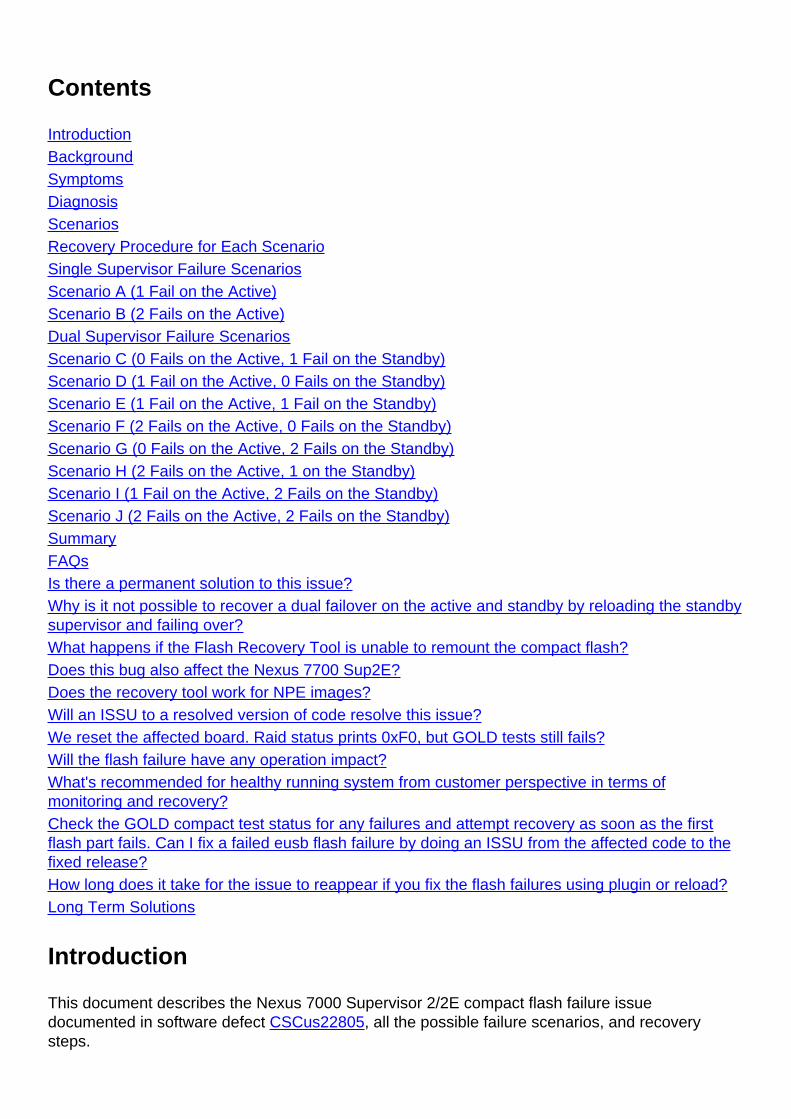
Compact flash diagnostic failure●
switch# show diagnostic result module 5
Current bootup diagnostic level: complete
Module 5: Supervisor module-2 (Standby)
Test results: (. = Pass, F = Fail, I = Incomplete,
U = Untested, A = Abort, E = Error disabled)
1) ASICRegisterCheck-------------> .
2) USB---------------------------> .
3) NVRAM-------------------------> .
4) RealTimeClock-----------------> .
5) PrimaryBootROM----------------> .
6) SecondaryBootROM--------------> .
7) CompactFlash------------------> F <=====
8) ExternalCompactFlash----------> .
9) PwrMgmtBus--------------------> U
10) SpineControlBus---------------> .
11) SystemMgmtBus-----------------> U
12) StatusBus---------------------> U
13) StandbyFabricLoopback---------> .
14) ManagementPortLoopback--------> .
15) EOBCPortLoopback--------------> .
16) OBFL--------------------------> .
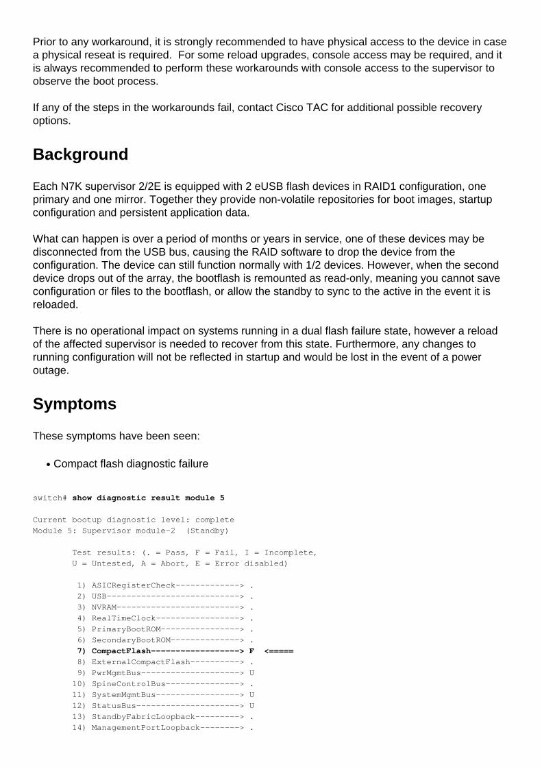
Unable to perform a 'copy run start'●
switch# show diagnostic result module 5
Current bootup diagnostic level: complete
Module 5: Supervisor module-2 (Standby)
Test results: (. = Pass, F = Fail, I = Incomplete,
U = Untested, A = Abort, E = Error disabled)
1) ASICRegisterCheck-------------> .
2) USB---------------------------> .
3) NVRAM-------------------------> .
4) RealTimeClock-----------------> .
5) PrimaryBootROM----------------> .
6) SecondaryBootROM--------------> .
7) CompactFlash------------------> F <=====
8) ExternalCompactFlash----------> .
9) PwrMgmtBus--------------------> U
10) SpineControlBus---------------> .
11) SystemMgmtBus-----------------> U
12) StatusBus---------------------> U
13) StandbyFabricLoopback---------> .
14) ManagementPortLoopback--------> .
15) EOBCPortLoopback--------------> .
16) OBFL--------------------------> .
eUSB becomes read-only or is non-responsive●
switch# show diagnostic result module 5
Current bootup diagnostic level: complete
Module 5: Supervisor module-2 (Standby)
Test results: (. = Pass, F = Fail, I = Incomplete,
U = Untested, A = Abort, E = Error disabled)
1) ASICRegisterCheck-------------> .
2) USB---------------------------> .
3) NVRAM-------------------------> .
4) RealTimeClock-----------------> .
5) PrimaryBootROM----------------> .
6) SecondaryBootROM--------------> .
7) CompactFlash------------------> F <=====
8) ExternalCompactFlash----------> .
9) PwrMgmtBus--------------------> U
10) SpineControlBus---------------> .
11) SystemMgmtBus-----------------> U
12) StatusBus---------------------> U
13) StandbyFabricLoopback---------> .
14) ManagementPortLoopback--------> .
15) EOBCPortLoopback--------------> .
16) OBFL--------------------------> .
ISSU failures, usually when trying to failover to the standby supervisor●
Diagnosis
To diagnose the current state of the compact flash cards you need to use these internalcommands. Note that the command will not parse out, and it must be typed out completely:
switch# show system internal raid | grep -A 1 "Current RAID status info"
switch# show system internal file /proc/mdstat
If there are two supervisors in the chassis, you will need to check the status of the standbysupervisor as well to determine which failure scenario you are facing. Check this by prependingthe command with the "slot x" keyword where "x" is the slot number of the standby supervisor.This allows you to run the command remotely on the standby.
switch# slot 2 show system internal raid | grep -A 1 "Current RAID status info"
switch# slot 2 show system internal file /proc/mdstat
These commands will give a lot of RAID statistics and events, but you are only concerned with thecurrent RAID information.
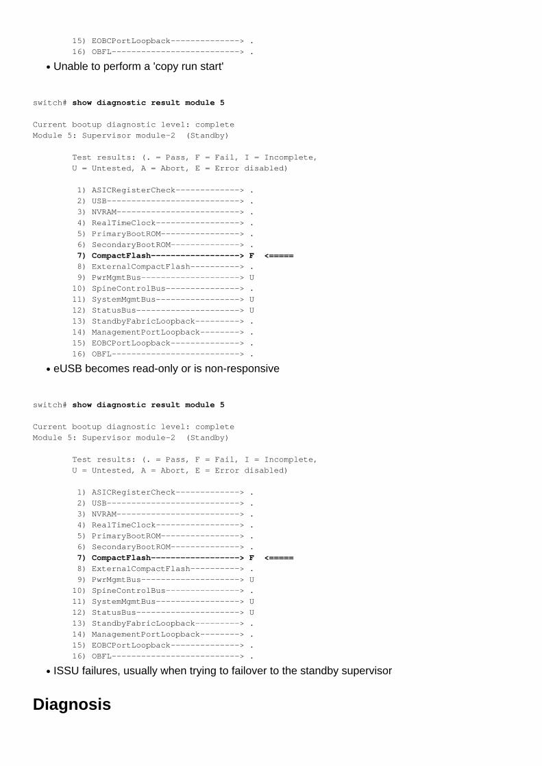
In the line "RAID data from CMOS", you want to look at the hex value after 0xa5. This will showhow many flashes may currently be facing an issue.
For example:
switch# show system internal raid | grep -A 1 "Current RAID status info"
Current RAID status info:
RAID data from CMOS = 0xa5 0xc3
From this output you want to look at the number beside of 0xa5 which is 0xc3. You can then usethese keys to determine if the primary or secondary compact flash has failed, or both. The aboveoutput shows 0xc3 which tells us that both the primary and the secondary compact flashes havefailed.
0xf0 No failures reported0xe1 Primary flash failed0xd2 Alternate (or mirror) flash failed0xc3 Both primary and alternate failed
In the "/proc/mdstat" output ensure that all disks are showing as "U", which represents "U"p:
switch# show system internal raid | grep -A 1 "Current RAID status info"
Current RAID status info:
RAID data from CMOS = 0xa5 0xc3
In this scenario you see that the primary compact flash is not up [_U]. A healthy output will showall blocks as [UU].
Note: Both outputs need to show as healthy (0xf0 and [UU]) to diagnose the supervisor ashealthy. So if you see a 0xf0 output in the CMOS data but see a [_U] in the /proc/mdstat, thebox is unhealthy.
Scenarios
To determine which scenario you are facing, you will need to use the above commands in the
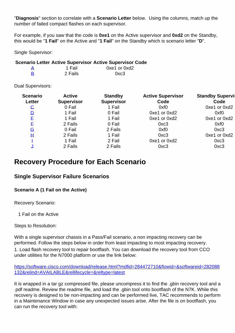
"Diagnosis" section to correlate with a Scenario Letter below. Using the columns, match up thenumber of failed compact flashes on each supervisor.
For example, if you saw that the code is 0xe1 on the Active supervisor and 0xd2 on the Standby,this would be "1 Fail" on the Active and "1 Fail" on the Standby which is scenario letter "D".
Single Supervisor:
Scenario Letter Active Supervisor Active Supervisor CodeA 1 Fail 0xe1 or 0xd2B 2 Fails 0xc3
Dual Supervisors:
ScenarioLetter
ActiveSupervisor
StandbySupervisor
Active SupervisorCode
Standby SupervisorCode
C 0 Fail 1 Fail 0xf0 0xe1 or 0xd2D 1 Fail 0 Fail 0xe1 or 0xd2 0xf0E 1 Fail 1 Fail 0xe1 or 0xd2 0xe1 or 0xd2F 2 Fails 0 Fail 0xc3 0xf0G 0 Fail 2 Fails 0xf0 0xc3H 2 Fails 1 Fail 0xc3 0xe1 or 0xd2I 1 Fail 2 Fail 0xe1 or 0xd2 0xc3J 2 Fails 2 Fails 0xc3 0xc3
Recovery Procedure for Each Scenario
Single Supervisor Failure Scenarios
Scenario A (1 Fail on the Active)
Recovery Scenario:
1 Fail on the Active
Steps to Resolution:
With a single supervisor chassis in a Pass/Fail scenario, a non impacting recovery can beperformed. Follow the steps below in order from least impacting to most impacting recovery.1. Load flash recovery tool to repair bootflash. You can download the recovery tool from CCOunder utilities for the N7000 platform or use the link below:
https://software.cisco.com/download/release.html?mdfid=284472710&flowid=&softwareid=282088132&relind=AVAILABLE&rellifecycle=&reltype=latest
It is wrapped in a tar gz compressed file, please uncompress it to find the .gbin recovery tool and a.pdf readme. Review the readme file, and load the .gbin tool onto bootflash of the N7K. While thisrecovery is designed to be non-impacting and can be performed live, TAC recommends to performin a Maintenance Window in case any unexpected issues arise. After the file is on bootflash, youcan run the recovery tool with:
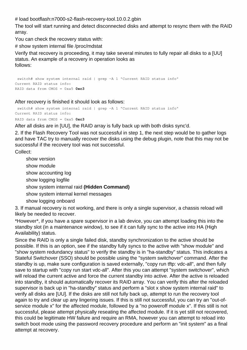
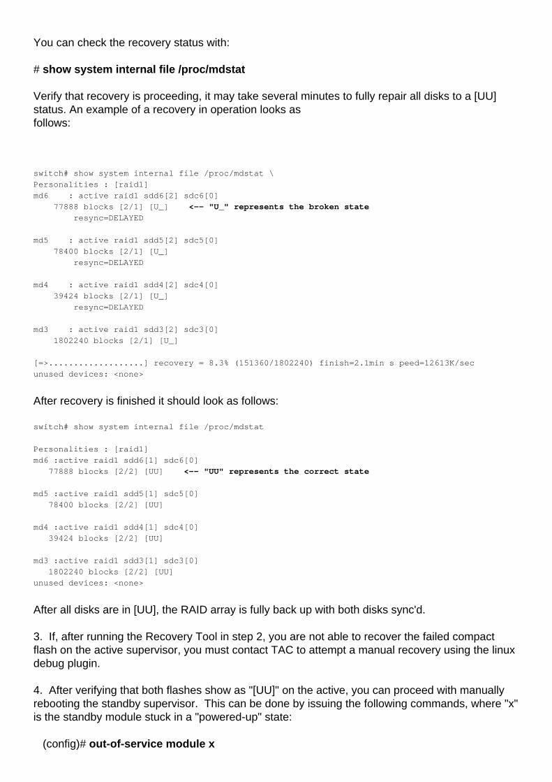
# load bootflash:n7000-s2-flash-recovery-tool.10.0.2.gbinThe tool will start running and detect disconnected disks and attempt to resync them with the RAIDarray.You can check the recovery status with:# show system internal file /proc/mdstatVerify that recovery is proceeding, it may take several minutes to fully repair all disks to a [UU]status. An example of a recovery in operation looks asfollows: switch# show system internal raid | grep -A 1 "Current RAID status info"
Current RAID status info:
RAID data from CMOS = 0xa5 0xc3
After recovery is finished it should look as follows: switch# show system internal raid | grep -A 1 "Current RAID status info"
Current RAID status info:
RAID data from CMOS = 0xa5 0xc3 After all disks are in [UU], the RAID array is fully back up with both disks sync'd.2. If the Flash Recovery Tool was not successful in step 1, the next step would be to gather logsand have TAC try to manually recover the disks using the debug plugin, note that this may not besuccessful if the recovery tool was not successful.Collect: show version show module show accounting log show logging logfile show system internal raid (Hidden Command) show system internal kernel messages show logging onboard3. If manual recovery is not working, and there is only a single supervisor, a chassis reload willlikely be needed to recover. *However*, if you have a spare supervisor in a lab device, you can attempt loading this into thestandby slot (in a maintenance window), to see if it can fully sync to the active into HA (HighAvailability) status. Since the RAID is only a single failed disk, standby synchronization to the active should bepossible. If this is an option, see if the standby fully syncs to the active with "show module" and"show system redundancy status" to verify the standby is in "ha-standby" status. This indicates aStateful Switchover (SSO) should be possible using the "system switchover" command. After thestandby is up, make sure configuration is saved externally, "copy run tftp: vdc-all", and then fullysave to startup with "copy run start vdc-all". After this you can attempt "system switchover", whichwill reload the current active and force the current standby into active. After the active is reloadedinto standby, it should automatically recover its RAID array. You can verify this after the reloadedsupervisor is back up in "ha-standby" status and perform a "slot x show system internal raid" toverify all disks are [UU]. If the disks are still not fully back up, attempt to run the recovery toolagain to try and clear up any lingering issues. If this is still not successful, you can try an "out-of-service module x" for the affected module, followed by a "no poweroff module x". If this still is notsuccessful, please attempt physically reseating the affected module. If it is yet still not recovered,this could be legitimate HW failure and require an RMA, however you can attempt to reload intoswitch boot mode using the password recovery procedure and perform an "init system" as a finalattempt at recovery.
If no spare supervisor is available, a full reload is necessarily with the "reload" command. In thiscase it would be recommended to have physical access to the device in case a physical reseat isrequired. Have all running configurations backed up externally, and is recommended to have thempresent on a USB disk along with the system and kickstart images to be safe. After the reload isperformed and the device is up, check the RAID status is [UU], and run the recovery tool if it doesnot look fully repaired. If the system is not coming up or the recovery tool is still not working,phsically reseat the supervisor module and observe the boot process via console. If a physicalreseat does not recover, break into loader using the password recovery procedure, enter switchboot mode by booting the kickstart image, then perform an "init system" to try and reinitialize thebootflash. This would wipe files on the bootflash, so it is crucial to have all necessary files andconfiguration backed up prior to these steps.If all else fails, it is likely a rare case of true hardware failure, and the supervisor would need to beRMA'd and possibly EFA'd. This is why all configuration must be externally backed up prior torecovery steps, in case an emergency RMA is required you have all necessary configuration toswiftly bring the system back up.
Scenario B (2 Fails on the Active)
Recovery Scenario:
2 Fails on the Active
Steps to Resolution:
In the scenario of a single supervisor with dual flash failure, a disruptive reload must be performedto recover.1. Backup all running configuration externally with "copy run tftp: vdc-all". Please note that in theoccurrence of dual flash failure, configuration changes since the system remounted to read-onlyare not present on the startup configuration. You can review "show run diff | i \+" to determinewhat changes were made since the dual flash failure so you will know what to add if the startupconfiguration is different than the running configuration upon reload. Note that it is possible that startup configuration is wiped upon reload of a supervisor with dualflash failure, which is why the configuration must be backed up externally. 2. Reload the device, it is strongly recommended to have console access and physical accessmay be required. The supervisor should reload and repair its bootflash. After the system is up,verify that both disks are up and running with the [UU] status in "show system internal file/proc/mdstat" and "show system internal raid". If both disks are up and running then therecovery is complete and you can work to restore all previous configuration. If recovery wasunsuccessful or partially successful go to step 3.
Note: It is commonly seen in instances of dual flash failures, a software reload might not fullyrecover the RAID and could require running the recovery tool or subsequent reloads torecover. In almost every occurrence, it has been resolved with a physical reseat of thesupervisor module. Therefore, if physical access to the device is possible, after backing upconfiguration externally, you can attempt a quick recovery that has the highest chance ofsucceeding by physically reseating the supervisor when ready to reload the device. This willfully remove power from the supervisor and should allow the recovery of both disks in theRAID. Proceed to Step 3 if the physical reseat recovery is only partial, or Step 4 if it isentirely not successful in that the system is not fully booting.
3. In the event of a partial recovery, meaning after reload one disk is up and the other is still downwith [U_] status, the next recommended step would be to attempt running the Flash Recovery Toolto resync the other disk. If the recovery tool is not successful, contact TAC to try manual recovery
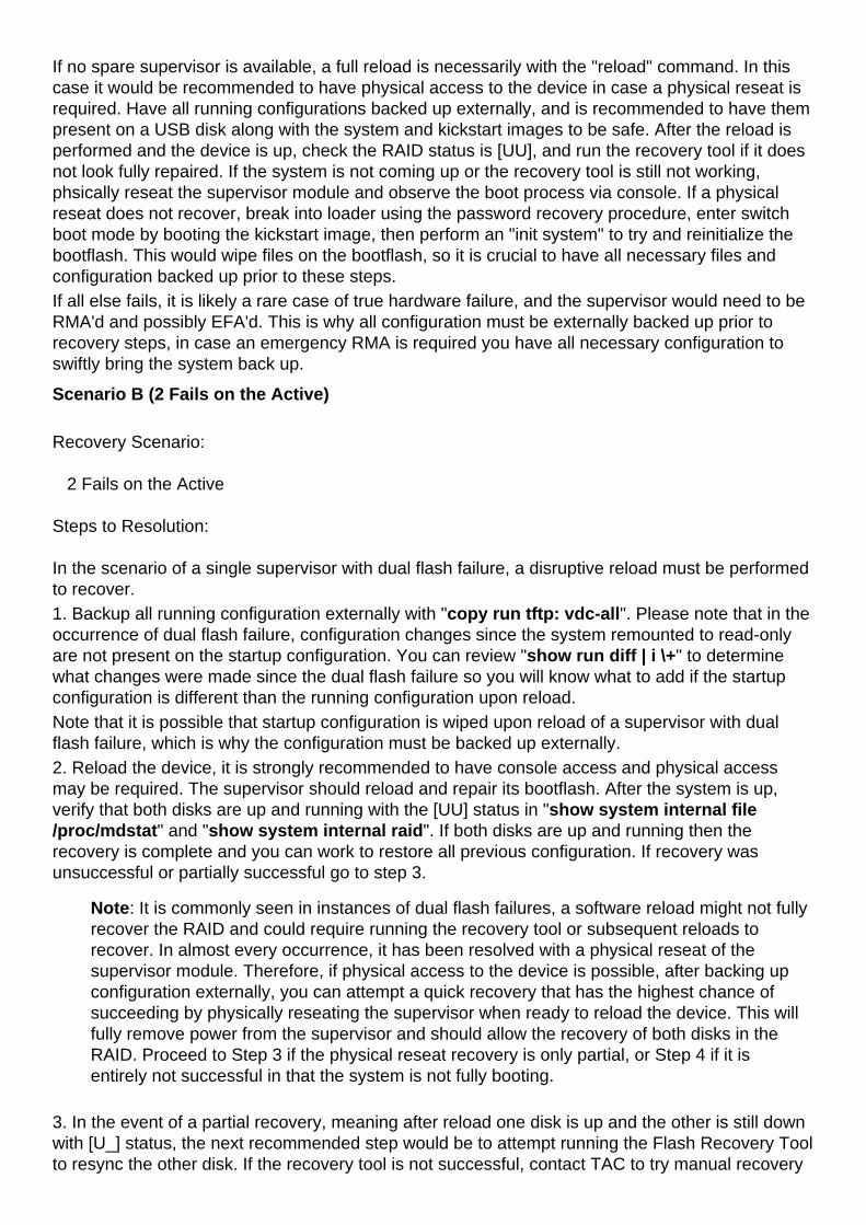
steps. A physical reseat of the supervisor can also be attempted.If the reload does not result in the supervisor fully booting, please perform a physical reseat of thesupervisor module. Note that it is commonly seen in a condition of dual flash failure that a software"reload" does not fully recover both disks as power is not fully removed from the module, which isaccomplished with a physical reseat. If the physical reseat is not successful go to step 4.4. In the event a physical reseat is not successful, the next step would be to break into loaderprompt using the password recovery steps, load the kickstart to switch boot mode, and perform an"init system", which will wipe the bootflash and attempt to repair the array. If init system completesor fails and still sees an issue, try another physical reseat.If all else fails, it is likely a rare case of true hardware failure, and the supervisor would need to be RMA'd and possibly EFA'd. This is why all configuration must be externally backed up prior torecovery steps, in case an emergency RMA is required you have all necessary configuration toswiftly bring the system back up.
Dual Supervisor Failure Scenarios
Scenario C (0 Fails on the Active, 1 Fail on the Standby)
Failure Scenario:
0 Fails on the Active
1 Fail on the Standby
Steps to Resolution:
In the scenario of a dual supervisor setup, with no flash failures on the active and a single failureon the standby, a non impacting recovery can be performed.
1. As the active has no failures and the standby only has a single failure, the Flash Recovery Toolcan be loaded onto the active and executed. After running the tool, it will automatically copy itselfto the standby and attempt to resync the array. The recovery tool can be downloaded here:
https://software.cisco.com/download/release.html?mdfid=284472710&flowid=&softwareid=282088132&relind=AVAILABLE&rellifecycle=&reltype=latest
Once you have downloaded the tool, unzipped it, and uploaded it to the bootflash of the box, youwill need to execute the following command to begin the recovery:
# load bootflash:n7000-s2-flash-recovery-tool.10.0.2.gbin
The tool will start running and detect disconnected disks and attempt to resync them with the RAIDarray.
You can check the recovery status with:
# show system internal file /proc/mdstat
Verify that recovery is proceeding, it may take several minutes to fully repair all disks to a [UU]status. An example of a recovery in operation looks asfollows:
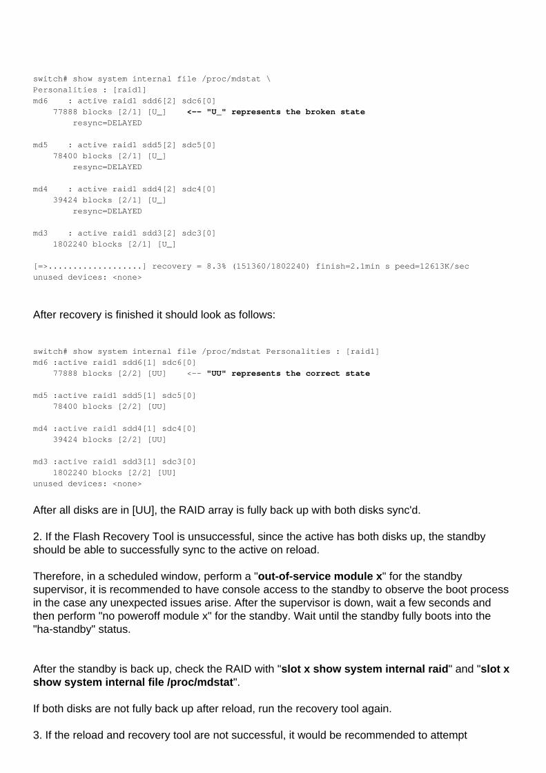
switch# show system internal file /proc/mdstat \
Personalities : [raid1]
md6 : active raid1 sdd6[2] sdc6[0]
77888 blocks [2/1] [U_] <-- "U_" represents the broken state
resync=DELAYED
md5 : active raid1 sdd5[2] sdc5[0]
78400 blocks [2/1] [U_]
resync=DELAYED
md4 : active raid1 sdd4[2] sdc4[0]
39424 blocks [2/1] [U_]
resync=DELAYED
md3 : active raid1 sdd3[2] sdc3[0]
1802240 blocks [2/1] [U_]
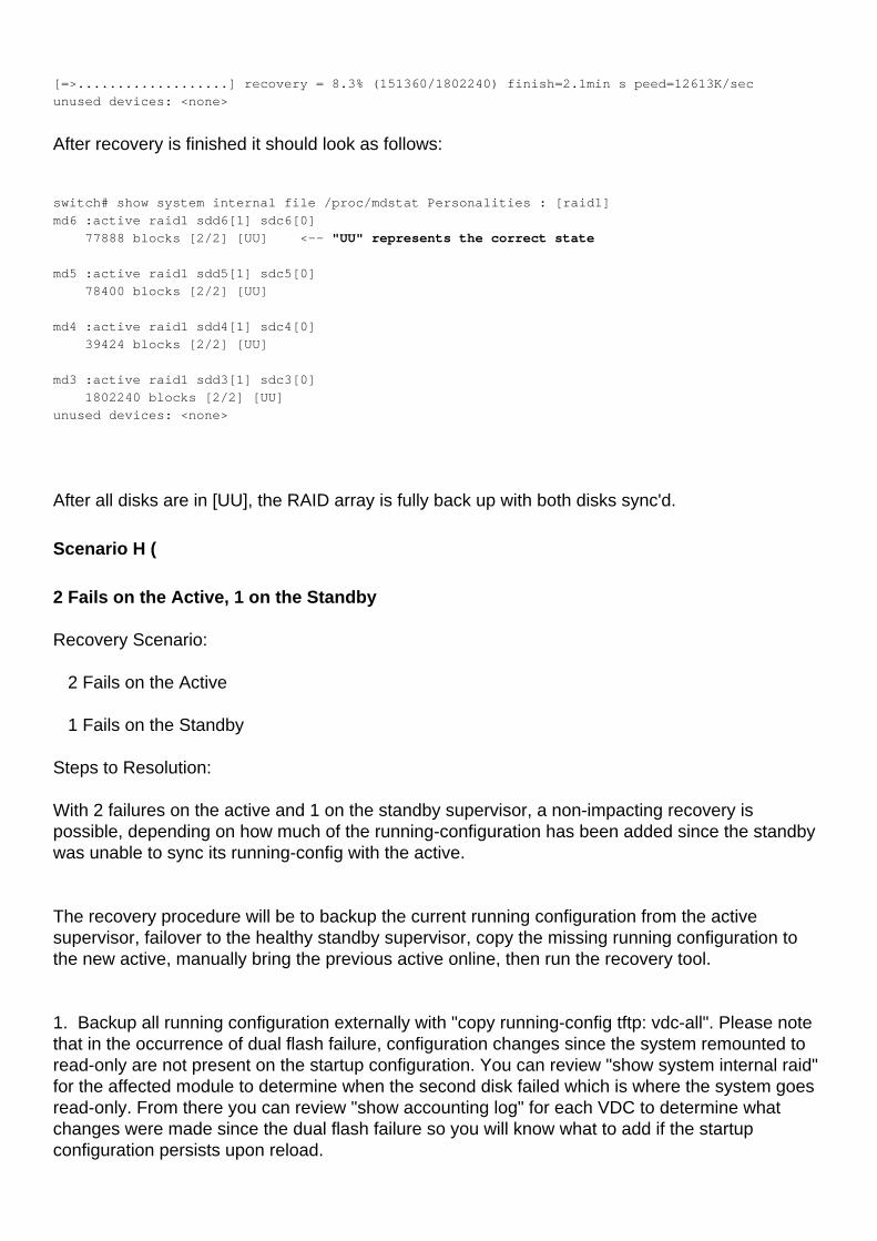
[=>...................] recovery = 8.3% (151360/1802240) finish=2.1min s peed=12613K/sec
unused devices: <none>
After recovery is finished it should look as follows:
switch# show system internal file /proc/mdstat Personalities : [raid1]
md6 :active raid1 sdd6[1] sdc6[0]
77888 blocks [2/2] [UU] <-- "UU" represents the correct state
md5 :active raid1 sdd5[1] sdc5[0]
78400 blocks [2/2] [UU]
md4 :active raid1 sdd4[1] sdc4[0]
39424 blocks [2/2] [UU]
md3 :active raid1 sdd3[1] sdc3[0]
1802240 blocks [2/2] [UU]
unused devices: <none>
After all disks are in [UU], the RAID array is fully back up with both disks sync'd.
2. If the Flash Recovery Tool is unsuccessful, since the active has both disks up, the standbyshould be able to successfully sync to the active on reload.
Therefore, in a scheduled window, perform a "out-of-service module x" for the standbysupervisor, it is recommended to have console access to the standby to observe the boot processin the case any unexpected issues arise. After the supervisor is down, wait a few seconds andthen perform "no poweroff module x" for the standby. Wait until the standby fully boots into the"ha-standby" status.
After the standby is back up, check the RAID with "slot x show system internal raid" and "slot xshow system internal file /proc/mdstat".
If both disks are not fully back up after reload, run the recovery tool again.
3. If the reload and recovery tool are not successful, it would be recommended to attempt
physically reseating the standby module in the window to try and clear the condition. If physicalreseat is not successful, try performing an "init system" from switch boot mode by following thepassword recovery steps to break into this mode during boot. If still unsuccessful, contact TAC toattempt manual recovery.
Scenario D (1 Fail on the Active, 0 Fails on the Standby)
Recovery Scenario:
1 Fail on the Active
0 Fails on the Standby
Steps to Resolution:
In the scenario of a dual supervisor setup, with 1 flash failure on the active and no failures on thestandby, a non impacting recovery can be performed by using the Flash Recovery Tool.
1. As the standby has no failures and the active only has a single failure, the Flash Recovery Toolcan be loaded onto the active and executed. After running the tool, it will automatically copy itselfto the standby and attempt to resync the array. The recovery tool can be downloaded here:
https://software.cisco.com/download/release.html?mdfid=284472710&flowid=&softwareid=282088132&relind=AVAILABLE&rellifecycle=&reltype=latest
Once you have downloaded the tool, unzipped it, and uploaded it to the bootflash of the active,you will need to execute the following command to begin the recovery:
# load bootflash:n7000-s2-flash-recovery-tool.10.0.2.gbin
The tool will start running and detect disconnected disks and attempt to resync them with the RAIDarray.
You can check the recovery status with:
# show system internal file /proc/mdstat
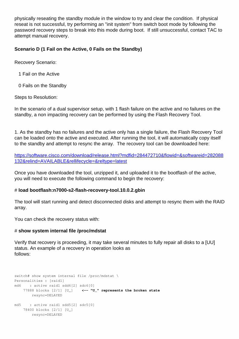
Verify that recovery is proceeding, it may take several minutes to fully repair all disks to a [UU]status. An example of a recovery in operation looks asfollows:
switch# show system internal file /proc/mdstat \
Personalities : [raid1]
md6 : active raid1 sdd6[2] sdc6[0]
77888 blocks [2/1] [U_] <-- "U_" represents the broken state
resync=DELAYED
md5 : active raid1 sdd5[2] sdc5[0]
78400 blocks [2/1] [U_]
resync=DELAYED

md4 : active raid1 sdd4[2] sdc4[0]
39424 blocks [2/1] [U_]
resync=DELAYED
md3 : active raid1 sdd3[2] sdc3[0]
1802240 blocks [2/1] [U_]
[=>...................] recovery = 8.3% (151360/1802240) finish=2.1min s peed=12613K/sec
unused devices: <none>
After recovery is finished it should look as follows:
switch# show system internal file /proc/mdstat Personalities : [raid1]
md6 :active raid1 sdd6[1] sdc6[0]
77888 blocks [2/2] [UU] <-- "UU" represents the correct state
md5 :active raid1 sdd5[1] sdc5[0]
78400 blocks [2/2] [UU]
md4 :active raid1 sdd4[1] sdc4[0]
39424 blocks [2/2] [UU]
md3 :active raid1 sdd3[1] sdc3[0]
1802240 blocks [2/2] [UU]
unused devices: <none>
After all disks are in [UU], the RAID array is fully back up with both disks sync'd.
2. If the Flash Recovery Tool is unsuccessful, the next step would be to perform a "systemswitchover" to failover the supervisor modules in a maintenance window.
Therefore, in a scheduled window, perform a "system switchover", it is recommended to haveconsole access to observe the boot process in the case any unexpected issues arise. Wait untilthe standby fully boots into the "ha-standby" status.
After the standby is back up, check the RAID with "slot x show system internal raid" and "slot xshow system internal file /proc/mdstat".
If both disks are not fully back up after reload, run the recovery tool again.
3. If the reload and recovery tool are not successful, it would be recommended to attemptphysically reseating the standby module in the window to try and clear the condition. If physicalreseat is not successful, try performing an "init system" from switch boot mode by following thepassword recovery steps to break into this mode during boot. If still unsuccessful, contact TAC toattempt manual recovery.
Scenario E (1 Fail on the Active, 1 Fail on the Standby)
Recovery Scenario:
1 Fail on the Active
1 Fail on the Standby
Steps to Resolution:
In the event of a single flash failure on both the active and standby, a non impacting workaroundcan still be accomplished.
1. As no supervisor is in a read-only state, the first step is to attempt using the Flash RecoveryTool.
The recovery tool can be downloaded here:
https://software.cisco.com/download/release.html?mdfid=284472710&flowid=&softwareid=282088132&relind=AVAILABLE&rellifecycle=&reltype=latest
Once you have downloaded the tool, unzipped it, and uploaded it to the bootflash of the active,you will need to execute the following command to begin the recovery:
# load bootflash:n7000-s2-flash-recovery-tool.10.0.2.gbin
It will automatically detect disconnected disks on the active and attempt repair, as well asautomatically copy itself to standby and detect and correct failures there.
You can check the recovery status with:
# show system internal file /proc/mdstat
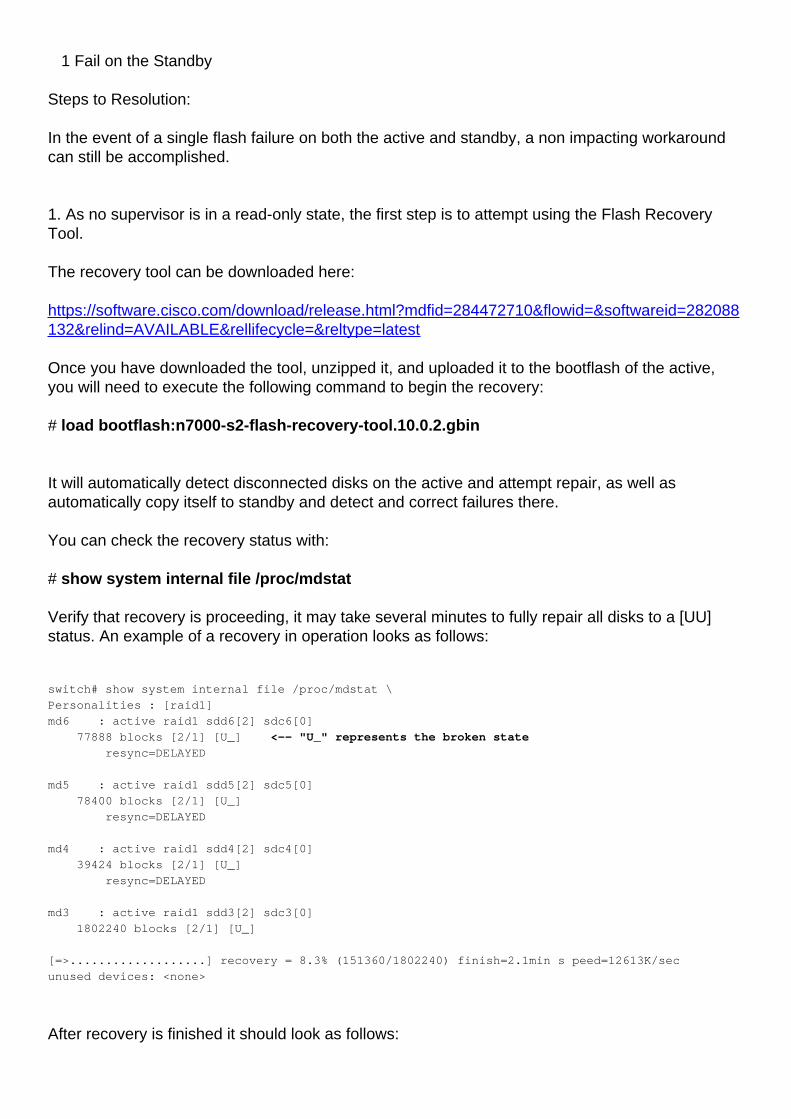
Verify that recovery is proceeding, it may take several minutes to fully repair all disks to a [UU]status. An example of a recovery in operation looks as follows:
switch# show system internal file /proc/mdstat \
Personalities : [raid1]
md6 : active raid1 sdd6[2] sdc6[0]
77888 blocks [2/1] [U_] <-- "U_" represents the broken state
resync=DELAYED
md5 : active raid1 sdd5[2] sdc5[0]
78400 blocks [2/1] [U_]
resync=DELAYED
md4 : active raid1 sdd4[2] sdc4[0]
39424 blocks [2/1] [U_]
resync=DELAYED
md3 : active raid1 sdd3[2] sdc3[0]
1802240 blocks [2/1] [U_]
[=>...................] recovery = 8.3% (151360/1802240) finish=2.1min s peed=12613K/sec
unused devices: <none>
After recovery is finished it should look as follows:
switch# show system internal file /proc/mdstat Personalities : [raid1]
md6 :active raid1 sdd6[1] sdc6[0]
77888 blocks [2/2] [UU] <-- "UU" represents the correct state
md5 :active raid1 sdd5[1] sdc5[0]
78400 blocks [2/2] [UU]
md4 :active raid1 sdd4[1] sdc4[0]
39424 blocks [2/2] [UU]
md3 :active raid1 sdd3[1] sdc3[0]
1802240 blocks [2/2] [UU]
unused devices: <none>
After all disks are in [UU], the RAID array is fully back up with both disks sync'd.
If both supervisors recover into the [UU] status, then recovery is complete. If recovery is partial ordid not succeed go to Step 2.
2. In the event that the recovery tool did not succeed, identify the current state of the RAID on themodules. If there is still a single flash failure on both, attempt a "system switchover" which willreload the current active and force the standby to the active role.
After the previous active is reloaded back into "ha-standby", check its RAID status as it should berecovered during the reload.If the supervisor successfully recovers after the switchover, you can try running the flash recoverytool again to try and repair the single disk failure on the current active supervisor, or another"system switchover" to reload the current active and force the previous active and current standbythat was repaired back to the active role. Verify the reloaded supervisor has both disks repairedagain, re-run the recovery tool if necessary.
3. If during this process the switchover is not fixing the RAID, perform an "out-of-service modulex" for the standby and then "no poweroff module x" to fully remove and re-apply power to themodule.
If out of service is not succesful, attempt a physical reseat of the standby.
If after running the recovery tool one supervisor recovers its RAID and the other still has a failure,force the supervisor with the single failure to standby with a "system switchover" if necessary. Ifthe supervisor with a single failure isalready standby, do an "out-of-service module x" for the standby and "no poweroff module x" tofully remove and reapply power to the module. If it is still not recovering, attempt a physical reseatof the module. In the event a reseat does not fix,break into the switch boot prompt using the password recovery procedure and do an "init system"to reinitialize the bootflash. If this is still unsuccessful, have TAC attempt manual recovery.
Note: If at any point the standby is stuck in a "powered-up" state and not "ha-standby", ifunable to get the standby fully up with the steps above, a chassis reload will be required.
Scenario F (2 Fails on the Active, 0 Fails on the Standby)
Recovery Scenario:
2 Fails on the Active
0 Fails on the Standby
Steps to Resolution:
With 2 failures on the active and 0 on the standby supervisor, a non-impacting recovery ispossible, depending on how much of the running-configuration has been added since the standbywas unable to sync its running-config with the active.
The recovery procedure will be to copy the current running configuration from the activesupervisor, failover to the healthy standby supervisor, copy the missing running configuration tothe new active, manually bring the previous active online, then run the recovery tool.
1. Backup all running configuration externally with "copy running-config tftp: vdc-all". Pleasenote that in the occurrence of dual flash failure, configuration changes since the systemremounted to read-only are not present on the startup configuration. You can review "showsystem internal raid" for the affected module to determine when the second disk failed which iswhere the system goes read-only. From there you can review "show accounting log" for eachVDC to determine what changes were made since the dual flash failure so you will know what toadd if the startup configuration persists upon reload. Please note that it is possible that startup configuration is wiped upon reload of a supervisor withdual flash failure, which is why the configuration must be backed up externally. 2. Once the running-configuration has been copied off of the active supervisor, it will be a goodidea to compare it to the start-up configuration to see what has changed since the last save. Thiscan be seen with "show startup-configuration". The differences will of course be completelydependent on the environment, but it is good to be aware of what may be missing when thestandby comes online as the active. It is also a good idea to have the differences already copiedout in a notepad so that they can be quickly added to the new active supervisor after theswitchover.
3. After the differences have been evaluated, you will need to perform a supervisor switchover. TAC recommends that this is done during a maintenance window, as unforseen issues mayoccur. The command to perform the failover to the standby will be "system switchover".
4. The switchover should occur very quickly and the new standby will begin rebooting. During thistime you will want to add any missing configuration back to the new active. This can be done bycopying the configuration from the TFTP server (or wherever it was saved previously) or by simplymanually adding the configuration in the CLI. In most instances the missing configurations arevery short and the CLI option will be the most feasible.
5. After some time the new standby supervisor may come back online in an "ha-standby" state,but what normally occurs is that it gets stuck in a "powered-up" state. The state can be viewedusing the "show module" command and referring to the "Status" column next to the module.
If the new standby comes up in a "powered-up" state, you will need to manually bring it backonline. This can be done by issuing the following commands, where "x" is the standby modulestuck in a "powered-up" state:
(config)# out-of-service module x
(config)# no poweroff module x
6. Once the standby is back online in an "ha-standby" state, you will then need to run the recoverytool to ensure that the recovery is complete. The tool can be downloaded at the following link:
https://software.cisco.com/download/release.html?mdfid=284472710&flowid=&softwareid=282088132&relind=AVAILABLE&rellifecycle=&reltype=latest
Once you have downloaded the tool, unzipped it, and uploaded it to the bootflash of the box, youwill need to execute the following command to begin the recovery:
# load bootflash:n7000-s2-flash-recovery-tool.10.0.2.gbin
The tool will start running and detect disconnected disks and attempt to resync them with the RAIDarray.
You can check the recovery status with:
# show system internal file /proc/mdstat
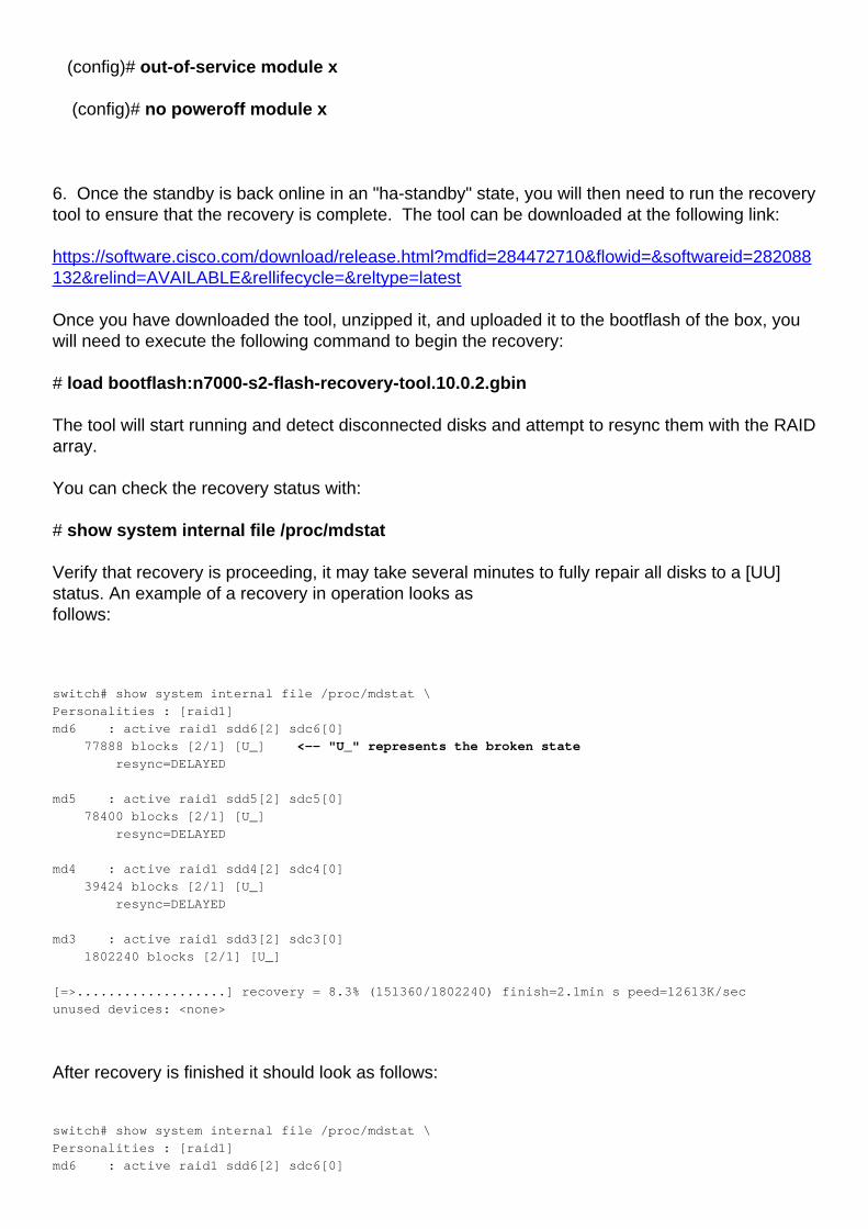
Verify that recovery is proceeding, it may take several minutes to fully repair all disks to a [UU]status. An example of a recovery in operation looks asfollows:
switch# show system internal file /proc/mdstat \
Personalities : [raid1]
md6 : active raid1 sdd6[2] sdc6[0]
77888 blocks [2/1] [U_] <-- "U_" represents the broken state
resync=DELAYED
md5 : active raid1 sdd5[2] sdc5[0]
78400 blocks [2/1] [U_]
resync=DELAYED
md4 : active raid1 sdd4[2] sdc4[0]
39424 blocks [2/1] [U_]
resync=DELAYED
md3 : active raid1 sdd3[2] sdc3[0]
1802240 blocks [2/1] [U_]
[=>...................] recovery = 8.3% (151360/1802240) finish=2.1min s peed=12613K/sec
unused devices: <none>
After recovery is finished it should look as follows:
switch# show system internal file /proc/mdstat \
Personalities : [raid1]
md6 : active raid1 sdd6[2] sdc6[0]
77888 blocks [2/1] [U_] <-- "U_" represents the broken state
resync=DELAYED
md5 : active raid1 sdd5[2] sdc5[0]
78400 blocks [2/1] [U_]
resync=DELAYED
md4 : active raid1 sdd4[2] sdc4[0]
39424 blocks [2/1] [U_]
resync=DELAYED
md3 : active raid1 sdd3[2] sdc3[0]
1802240 blocks [2/1] [U_]
[=>...................] recovery = 8.3% (151360/1802240) finish=2.1min s peed=12613K/sec
unused devices: <none>
After all disks are in [UU], the RAID array is fully back up with both disks sync'd.
Scenario G (0 Fails on the Active, 2 Fails on the Standby)
0 Fails on the Active, 2 on the Standby
Recovery Scenario:
0 Fails on the Active
2 Fails on the Standby
Steps to Resolution:
With 0 failures on the active and 2 on the standby supervisor, a non-impacting recovery ispossible.
The recovery procedure will be to perform a reload of the standby.
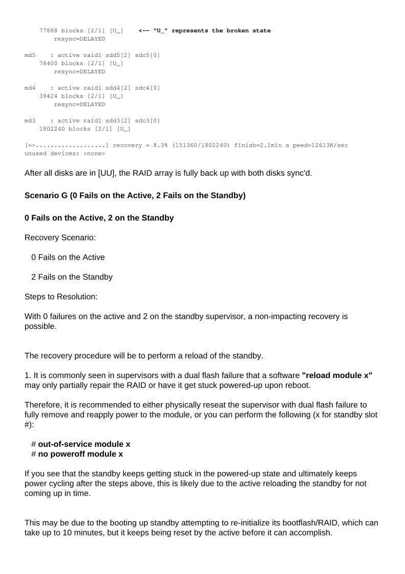
1. It is commonly seen in supervisors with a dual flash failure that a software "reload module x"may only partially repair the RAID or have it get stuck powered-up upon reboot.
Therefore, it is recommended to either physically reseat the supervisor with dual flash failure tofully remove and reapply power to the module, or you can perform the following (x for standby slot#):
# out-of-service module x # no poweroff module x
If you see that the standby keeps getting stuck in the powered-up state and ultimately keepspower cycling after the steps above, this is likely due to the active reloading the standby for notcoming up in time.
This may be due to the booting up standby attempting to re-initialize its bootflash/RAID, which cantake up to 10 minutes, but it keeps being reset by the active before it can accomplish.
To resolve this, configure the following using 'x' for the standby slot # stuck in powered-up:
(config)# system standby manual-boot (config)# reload module x force-dnld The above will make it so the active does not automatically reset the standby, and then reloadthe standby and force it to sync its image from the active. Wait 10-15 minutes to see if the standby is finally able to get to ha-standby status. After it is inha-standby status, re-enable automatic reboots of the standby with: (config)# system no standby manual-boot
6. Once the standby is back online in an "ha-standby" state, you will then need to run the recoverytool to ensure that the recovery is complete. The tool can be downloaded at the following link:
https://software.cisco.com/download/release.html?mdfid=284472710&flowid=&softwareid=282088132&relind=AVAILABLE&rellifecycle=&reltype=latest
Once you have downloaded the tool, unzipped it, and uploaded it to the bootflash of the box, youwill need to execute the following command to begin the recovery:
# load bootflash:n7000-s2-flash-recovery-tool.10.0.2.gbin
The tool will start running and detect disconnected disks and attempt to resync them with the RAIDarray.
You can check the recovery status with:
# show system internal file /proc/mdstat
Verify that recovery is proceeding, it may take several minutes to fully repair all disks to a [UU]status. An example of a recovery in operation looks asfollows:
switch# show system internal file /proc/mdstat
Personalities : [raid1]
md6 : active raid1 sdd6[2] sdc6[0]
77888 blocks [2/1] [U_] <-- "U_" represents the broken state
resync=DELAYED
md5 : active raid1 sdd5[2] sdc5[0]
78400 blocks [2/1] [U_]
resync=DELAYED
md4 : active raid1 sdd4[2] sdc4[0]
39424 blocks [2/1] [U_]
resync=DELAYED
md3 : active raid1 sdd3[2] sdc3[0]
1802240 blocks [2/1] [U_]
[=>...................] recovery = 8.3% (151360/1802240) finish=2.1min s peed=12613K/sec
unused devices: <none>
After recovery is finished it should look as follows:
switch# show system internal file /proc/mdstat Personalities : [raid1]
md6 :active raid1 sdd6[1] sdc6[0]
77888 blocks [2/2] [UU] <-- "UU" represents the correct state
md5 :active raid1 sdd5[1] sdc5[0]
78400 blocks [2/2] [UU]
md4 :active raid1 sdd4[1] sdc4[0]
39424 blocks [2/2] [UU]
md3 :active raid1 sdd3[1] sdc3[0]
1802240 blocks [2/2] [UU]
unused devices: <none>
After all disks are in [UU], the RAID array is fully back up with both disks sync'd.
Scenario H (
2 Fails on the Active, 1 on the Standby
Recovery Scenario:
2 Fails on the Active
1 Fails on the Standby
Steps to Resolution:
With 2 failures on the active and 1 on the standby supervisor, a non-impacting recovery ispossible, depending on how much of the running-configuration has been added since the standbywas unable to sync its running-config with the active.
The recovery procedure will be to backup the current running configuration from the activesupervisor, failover to the healthy standby supervisor, copy the missing running configuration tothe new active, manually bring the previous active online, then run the recovery tool.
1. Backup all running configuration externally with "copy running-config tftp: vdc-all". Please notethat in the occurrence of dual flash failure, configuration changes since the system remounted toread-only are not present on the startup configuration. You can review "show system internal raid"for the affected module to determine when the second disk failed which is where the system goesread-only. From there you can review "show accounting log" for each VDC to determine whatchanges were made since the dual flash failure so you will know what to add if the startupconfiguration persists upon reload.
Please note that it is possible that startup configuration is wiped upon reload of a supervisor withdual flash failure, which is why the configuration must be backed up externally.
2. Once the running-configuration has been copied off of the active supervisor, it will be a goodidea to compare it to the start-up configuration to see what has changed since the last save. Thiscan be seen with "show startup-configuration". The differences will of course be completelydependent on the environment, but it is good to be aware of what may be missing when thestandby comes online as the active. It is also a good idea to have the differences already copiedout in a notepad so that they can be quickly added to the new active supervisor after theswitchover.
3. After the differences have been evaluated, you will need to perform a supervisor switchover. TAC recommends that this is done during a maintenance window, as unforseen issues mayoccur. The command to perform the failover to the standby will be "system switchover".
4. The switchover should occur very quickly and the new standby will begin rebooting. During thistime you will want to add any missing configuration back to the new active. This can be done bycopying the configuration from the TFTP server (or wherever it was saved previously) or by simplymanually adding the configuration in the CLI, do not copy directly from tftp to running-configuration, copy to bootflash first, and then to running configuration. In most instances themissing configurations are very short and the CLI option will be the most feasible.
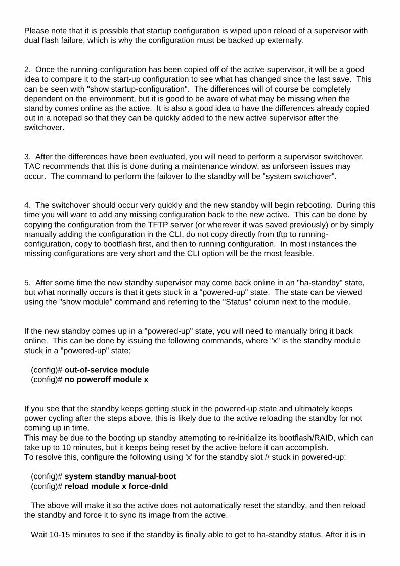
5. After some time the new standby supervisor may come back online in an "ha-standby" state,but what normally occurs is that it gets stuck in a "powered-up" state. The state can be viewedusing the "show module" command and referring to the "Status" column next to the module.
If the new standby comes up in a "powered-up" state, you will need to manually bring it backonline. This can be done by issuing the following commands, where "x" is the standby modulestuck in a "powered-up" state:
(config)# out-of-service module (config)# no poweroff module x If you see that the standby keeps getting stuck in the powered-up state and ultimately keepspower cycling after the steps above, this is likely due to the active reloading the standby for notcoming up in time.This may be due to the booting up standby attempting to re-initialize its bootflash/RAID, which cantake up to 10 minutes, but it keeps being reset by the active before it can accomplish.To resolve this, configure the following using 'x' for the standby slot # stuck in powered-up:
(config)# system standby manual-boot (config)# reload module x force-dnld The above will make it so the active does not automatically reset the standby, and then reloadthe standby and force it to sync its image from the active. Wait 10-15 minutes to see if the standby is finally able to get to ha-standby status. After it is in
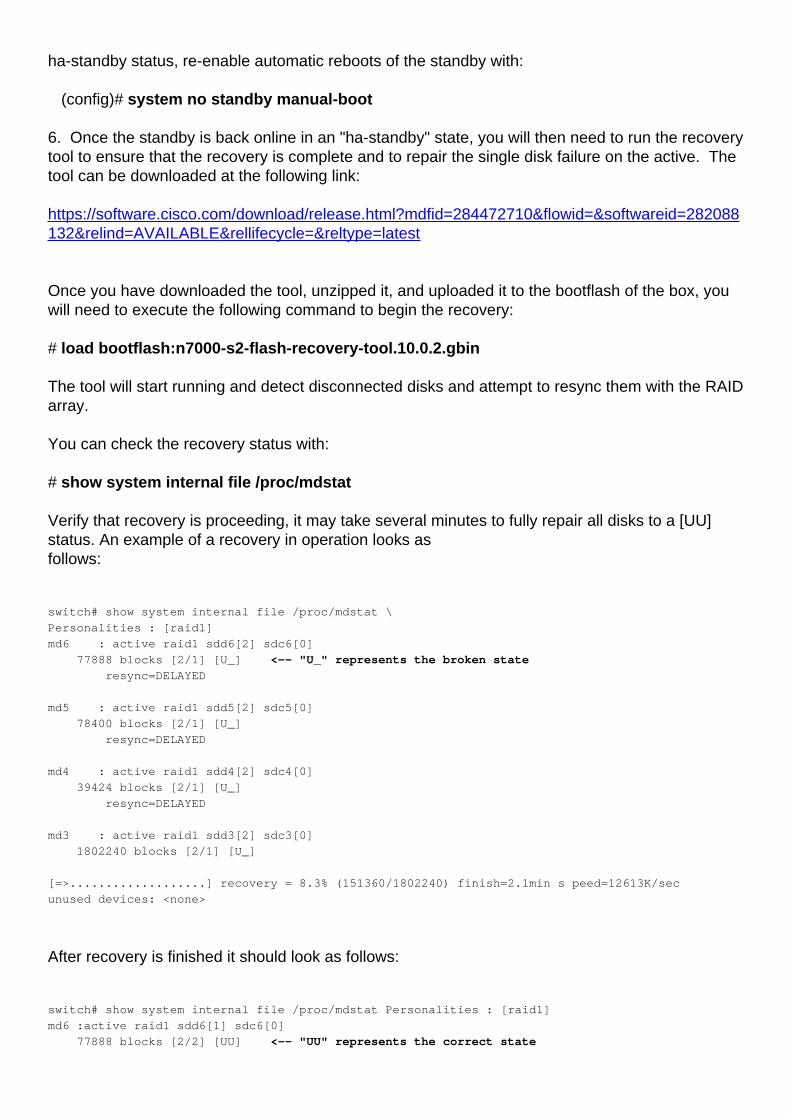
ha-standby status, re-enable automatic reboots of the standby with: (config)# system no standby manual-boot 6. Once the standby is back online in an "ha-standby" state, you will then need to run the recoverytool to ensure that the recovery is complete and to repair the single disk failure on the active. Thetool can be downloaded at the following link:
https://software.cisco.com/download/release.html?mdfid=284472710&flowid=&softwareid=282088132&relind=AVAILABLE&rellifecycle=&reltype=latest
Once you have downloaded the tool, unzipped it, and uploaded it to the bootflash of the box, youwill need to execute the following command to begin the recovery:
# load bootflash:n7000-s2-flash-recovery-tool.10.0.2.gbin
The tool will start running and detect disconnected disks and attempt to resync them with the RAIDarray.
You can check the recovery status with:
# show system internal file /proc/mdstat
Verify that recovery is proceeding, it may take several minutes to fully repair all disks to a [UU]status. An example of a recovery in operation looks asfollows:
switch# show system internal file /proc/mdstat \
Personalities : [raid1]
md6 : active raid1 sdd6[2] sdc6[0]
77888 blocks [2/1] [U_] <-- "U_" represents the broken state
resync=DELAYED
md5 : active raid1 sdd5[2] sdc5[0]
78400 blocks [2/1] [U_]
resync=DELAYED
md4 : active raid1 sdd4[2] sdc4[0]
39424 blocks [2/1] [U_]
resync=DELAYED
md3 : active raid1 sdd3[2] sdc3[0]
1802240 blocks [2/1] [U_]
[=>...................] recovery = 8.3% (151360/1802240) finish=2.1min s peed=12613K/sec
unused devices: <none>
After recovery is finished it should look as follows:
switch# show system internal file /proc/mdstat Personalities : [raid1]
md6 :active raid1 sdd6[1] sdc6[0]
77888 blocks [2/2] [UU] <-- "UU" represents the correct state
md5 :active raid1 sdd5[1] sdc5[0]
78400 blocks [2/2] [UU]
md4 :active raid1 sdd4[1] sdc4[0]
39424 blocks [2/2] [UU]
md3 :active raid1 sdd3[1] sdc3[0]
1802240 blocks [2/2] [UU]
unused devices: <none>
After all disks are in [UU], the RAID array is fully back up with both disks sync'd.
If the current active with a single failure is not recovered by the recovery tool, attempt another"system switchover" ensuring your current standby is in "ha-standby" status. If still not successfullplease contact Cisco TAC
Scenario I (1 Fail on the Active, 2 Fails on the Standby)
Recovery Scenario:
1 Fail on the Active
2 Fails on the Standby
Steps to Resolution:
In a dual supervisor scenario with 1 failure on the active and 2 failures on the standby supervisor anon-impacting recovery can be possible, but in many cases a reload may be necessary.
The process will be to first back up all running configuratoins, then attempt to recover the failedcompact flash on the active usingt he recovery tool, then, if successful, you will manually reloadthe standby and run the recovery tool again. If the initial recovery attempt is unable to recover thefailed flash on the active, TAC must be engaged to attempt a manual recovery using the debugplugin.
1. Backup all running configuration externally with "copy running-config tftp: vdc-all". You mayalso copy the running-config to a local USB stick if a TFTP server is not set up in the environment.
2. Once the current running-configuration is backed up, you will then need to run the recovery toolto attempt a recovery of the failed flash on the active. The tool can be downloaded at the followinglink:
https://software.cisco.com/download/release.html?mdfid=284472710&flowid=&softwareid=282088132&relind=AVAILABLE&rellifecycle=&reltype=latest
Once you have downloaded the tool, unzipped it, and uploaded it to the bootflash of the box, youwill need to execute the following command to begin the recovery:
# load bootflash:n7000-s2-flash-recovery-tool.10.0.2.gbin
The tool will start running and detect disconnected disks and attempt to resync them with the RAIDarray.
You can check the recovery status with:
# show system internal file /proc/mdstat
Verify that recovery is proceeding, it may take several minutes to fully repair all disks to a [UU]status. An example of a recovery in operation looks asfollows:
switch# show system internal file /proc/mdstat \
Personalities : [raid1]
md6 : active raid1 sdd6[2] sdc6[0]
77888 blocks [2/1] [U_] <-- "U_" represents the broken state
resync=DELAYED
md5 : active raid1 sdd5[2] sdc5[0]
78400 blocks [2/1] [U_]
resync=DELAYED
md4 : active raid1 sdd4[2] sdc4[0]
39424 blocks [2/1] [U_]
resync=DELAYED
md3 : active raid1 sdd3[2] sdc3[0]
1802240 blocks [2/1] [U_]
[=>...................] recovery = 8.3% (151360/1802240) finish=2.1min s peed=12613K/sec
unused devices: <none>
After recovery is finished it should look as follows:
switch# show system internal file /proc/mdstat
Personalities : [raid1]
md6 :active raid1 sdd6[1] sdc6[0]
77888 blocks [2/2] [UU] <-- "UU" represents the correct state
md5 :active raid1 sdd5[1] sdc5[0]
78400 blocks [2/2] [UU]
md4 :active raid1 sdd4[1] sdc4[0]
39424 blocks [2/2] [UU]
md3 :active raid1 sdd3[1] sdc3[0]
1802240 blocks [2/2] [UU]
unused devices: <none>
After all disks are in [UU], the RAID array is fully back up with both disks sync'd.
3. If, after running the Recovery Tool in step 2, you are not able to recover the failed compactflash on the active supervisor, you must contact TAC to attempt a manual recovery using the linuxdebug plugin.
4. After verifying that both flashes show as "[UU]" on the active, you can proceed with manuallyrebooting the standby supervisor. This can be done by issuing the following commands, where "x"is the standby module stuck in a "powered-up" state:
(config)# out-of-service module x

(config)# no poweroff module x
This should bring the standby supervisor back into an "ha-standby" state (this is checked byviewing the Status column in the "show module" output). If this is successful proceed to step 6, ifnot, try the procedure outlined in step 5.
5. If you see that the standby keeps getting stuck in the powered-up state and ultimately keepspower cycling after the steps above, this is likely due to the active reloading the standby for notcoming up in time. This may be due to the booting up standby attempting to re-initialize itsbootflash/RAID, which can take up to 10 minutes, but it keeps being reset by the active before itcan accomplish. To resolve this, configure the following using 'x' for the standby slot # stuck inpowered-up:
(config)# system standby manual-boot(config)# reload module x force-dnld
The above will make it so the active does not automatically reset the standby, and then reload thestandby and force it to sync its image from the active.
Wait 10-15 minutes to see if the standby is finally able to get to ha-standby status. After it is in ha-standby status, re-enable automatic reboots of the standby with:
(config)# system no standby manual-boot
6. Once the standby is back online in an "ha-standby" state, you will then need to run the recoverytool to ensure that the recovery is complete. You can run the same tool that you have on theactive for this step, no additional download is needed as the recovery tool runs on the active andthe standby.
Scenario J (2 Fails on the Active, 2 Fails on the Standby)
Recovery Scenario:
2 Fails on the Active
2 Fails on the Standby
Steps to Resolution:
In a dual supervisor with dual flash failure, a disruptive reload must be performed to recover.Please follow the following steps to resolution:1. Backup all running configuration externally with "copy running-config tftp: vdc-all". Pleasenote that in the occurrence of dual flash failure, configuration changes since the systemremounted to read-only are not present on the startup configuration. You can review "showsystem internal raid" for the affected module to determine when the second disk failed which iswhere the system goes read-only. From there you can review "show accounting log" for eachVDC to determine what changes were made since the dual flash failure so you will know what toadd if the startup configuration persists upon reload. Please note that it is possible that startup configuration is wiped upon reload of a supervisor withdual flash failure, which is why the configuration must be backed up externally. 2. Reload the device, it is strongly recommended to have console access and physical accessmay be required. The supervisor should reload and repair its bootflash. After the system is up,
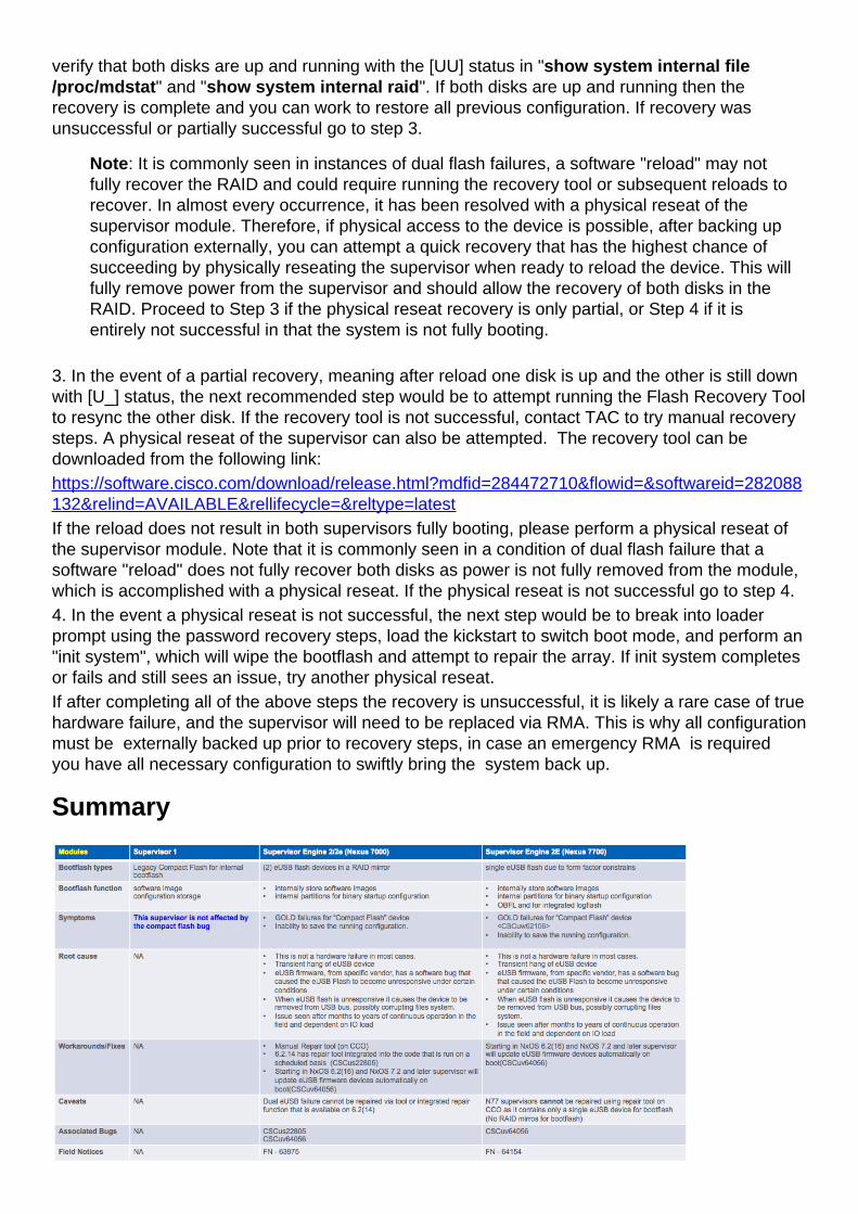
verify that both disks are up and running with the [UU] status in "show system internal file/proc/mdstat" and "show system internal raid". If both disks are up and running then therecovery is complete and you can work to restore all previous configuration. If recovery wasunsuccessful or partially successful go to step 3.
Note: It is commonly seen in instances of dual flash failures, a software "reload" may notfully recover the RAID and could require running the recovery tool or subsequent reloads torecover. In almost every occurrence, it has been resolved with a physical reseat of thesupervisor module. Therefore, if physical access to the device is possible, after backing upconfiguration externally, you can attempt a quick recovery that has the highest chance ofsucceeding by physically reseating the supervisor when ready to reload the device. This willfully remove power from the supervisor and should allow the recovery of both disks in theRAID. Proceed to Step 3 if the physical reseat recovery is only partial, or Step 4 if it isentirely not successful in that the system is not fully booting.
3. In the event of a partial recovery, meaning after reload one disk is up and the other is still downwith [U_] status, the next recommended step would be to attempt running the Flash Recovery Toolto resync the other disk. If the recovery tool is not successful, contact TAC to try manual recoverysteps. A physical reseat of the supervisor can also be attempted. The recovery tool can bedownloaded from the following link:https://software.cisco.com/download/release.html?mdfid=284472710&flowid=&softwareid=282088132&relind=AVAILABLE&rellifecycle=&reltype=latestIf the reload does not result in both supervisors fully booting, please perform a physical reseat ofthe supervisor module. Note that it is commonly seen in a condition of dual flash failure that asoftware "reload" does not fully recover both disks as power is not fully removed from the module,which is accomplished with a physical reseat. If the physical reseat is not successful go to step 4.4. In the event a physical reseat is not successful, the next step would be to break into loaderprompt using the password recovery steps, load the kickstart to switch boot mode, and perform an"init system", which will wipe the bootflash and attempt to repair the array. If init system completesor fails and still sees an issue, try another physical reseat.If after completing all of the above steps the recovery is unsuccessful, it is likely a rare case of truehardware failure, and the supervisor will need to be replaced via RMA. This is why all configurationmust be externally backed up prior to recovery steps, in case an emergency RMA is required you have all necessary configuration to swiftly bring the system back up.
Summary
FAQs
Is there a permanent solution to this issue?
See the Long Term Solutions section below.
Why is it not possible to recover a dual failover on the active and standby byreloading the standby supervisor and failing over?
The reason this is not possible is because in order to allow the standby supervisor to come up inan "ha-standby" state, the active supervisor must write several things to its compact flash (SNMPinfo, etc.), which it cannot do if it has a dual flash failure itself.
What happens if the Flash Recovery Tool is unable to remount the compactflash?
Contact Cisco TAC for options in this scenario.
Does this bug also affect the Nexus 7700 Sup2E?
There is a separate defect for the N7700 Sup2E - CSCuv64056 . The recovery tool will not workfor the N7700.
Does the recovery tool work for NPE images?
The recovery tool does not work for NPE images.
Will an ISSU to a resolved version of code resolve this issue?
No. An ISSU will utilize a supervisor switchover, which may not perform correctly due to thecompact flash failure.
We reset the affected board. Raid status prints 0xF0, but GOLD tests stillfails?
RAID status bits gets reset after board reset after applying auto recovery.However not all failure conditions can be recovered automatically.If the RAID status bits are not printed as [2/2] [UU], recovery is incomplete.Follow the recovery steps listed
Will the flash failure have any operation impact?
No, But system may not boot back up on a power failure. Startup configs will be lost as well.
What's recommended for healthy running system from customer perspectivein terms of monitoring and recovery?
Check the GOLD compact test status for any failures and attempt recovery assoon as the first flash part fails.
Can I fix a failed eusb flash failure by doing an ISSU from the affected code tothe fixed release?
ISSU will not fix failed eUSB. The best option is to run the recovery tool for single eusb failure onthe sup or reload the sup incase of dual eusb failure.Once the issue is corrected then do the upgrade. The fix for CSCus22805 helps corrects singleeusb failure ONLY and it does so by by scanning the system at regular interval and attempts toreawaken inaccessible or read-only eUSB using the script.It is rare to see both eusb flash failure on the supervisor occurring simultaneously hence thisworkaround will be effective.
How long does it take for the issue to reappear if you fix the flash failuresusing plugin or reload?
Generally it is seen by a longer uptime. This is not exactly quantified and can range from a year orlonger. The bottom line is that the more stress on the eusb flash in terms of read writes, the higherthe probability of the system running into this scenario.
Show system internal raid shows the flash status twice in different sections. Also these sectionsare not consistentThe first section shows the current status and the second section shows the bootup status.The current status is what matters and it should always show as UU.
Long Term Solutions
This defect has a workaround in 6.2(14), but the firmware fix was added to 6.2(16) and 7.2(x) andlater.
It is advisable to upgrade to a release with the firmware fix to completely resolve this issue.
If you are unable to upgrade to a fixed version of NXOS there are two possible solutions.
Solution 1 is to run the flash recovery tool proactively every week using the scheduler. Thefollowing scheduler configuratoin with the flash recovery tool in the bootflash:
feature schedulerscheduler job name Flash_Job
copy bootflash:/n7000-s2-flash-recovery-tool.10.0.2.gbinbootflash:/flash_recovery_tool_copy

load bootflash:/flash_recovery_tool_copy
exitscheduler schedule name Flash_Recovery job name Flash_Job time weekly 7
Notes:
The flash recovery needs to have the same name and be in the bootflash.●
The 7 in the "time weekly 7" configuration represents a day of the week, Saturday in this case.●
The maximum frequency that Cisco recommends running the flash recovery tool is once aweek.
●
Solution 2 is documented at the following technote link


![Kapitel 4) KOHLENHYDRATE [Kompatibilitätsmodus]biochemietrainingscamp.de/stoff/kh/Glykolyse.pdf · Succinat dehydrogenase Cytochrom C+2e H2 2H + 2e Cytochrom b+c +2e +2e 2H III I](https://img.pdfslide.net/doc/110x75/5d4e6d6f88c99303708bac73/kapitel-4-kohlenhydrate-kompatibilitaetsmodusbi-succinat-dehydrogenase-cytochrom.jpg)