Embed Size (px)
Citation preview
Novel Escapement Mechanism using a Compliant Mechanism and a
Piezoelectric Actuator
A Thesis
Submitted to the Faculty of the
WORCESTER POLYTECHNIC INSTITUTE
in partial requirement for the
Degree of Master of Science
in
Mechanical Engineering
by:
__________________________________ Girish S. Mali
April 27, 2007
Approved:
_______________________________________________ Professor Robert L. Norton, Advisor
_______________________________________________ Professor Yong-Mo Moon, Thesis Committee Member
_______________________________________________ Professor Mikhail Dimentberg, Thesis Committee Member
___________________________________________________ Professor Cosme Furlong, Graduate Committee Representative

i
ABSTRACT
Escapement mechanisms hold back a stream of parts driven either by mechanical or
pneumatic means for a length of time and release a single part as required to an assembly
station. They are used in most automatic multi-component assembly equipment. They
occupy a significant design space and have dynamic characteristics of their own. This
research aimed to develop a novel high speed mechanism for parts escapement that
occupies less design space and contributes less to the dynamic activity of the structure.
Several conceptual mechanisms were generated and evaluated. A compliant mechanism
that amplifies the very small displacement of a piezo actuator was selected for detailed
design. A proof of concept prototype was fabricated and tested. A piezo stack was used to
bend a thin, spring steel, compliant beam. Its deflection was further amplified by
attaching a comparatively rigid beam extension at the end of the compliant section. The
mechanism escapes parts at 16 Hz using constrained layer damping on the beam to
reduce vibrations. The concept is feasible to use on production machinery and provides
advantages in terms of higher operating speeds and compactness. The concept could also
be used where there is a requirement of high speed gating.

ii
ACKNOWLEDGEMENTS
I would like to thank Professor Robert L. Norton and Professor Yong-Mo Moon for
providing me with motivation and guidance through out the progress of the research.
Both of them helped me unravel a lot many territories in my ignorance. Thanks to Tim
Sweet for providing with a novel idea to work on and The Gillette Company for
sponsoring the research.
Thanks to people and friends at WPI who helped in manufacture and testing of
mechanism. I would also like to thank my family and friends for providing an
unwavering support in all my endeavors.

iii
CONTENTS LIST OF FIGURES……………………………………...………………………………..v
LIST OF TABLES………………………………………………...…………………......vii
1. Introduction................................................................................................................ 1
2. Project Scope ............................................................................................................. 3
2.1. Goal Statement........................................................................................................ 3 2.2. Project Objective..................................................................................................... 3 2.3. Proposed Approach................................................................................................. 3
3. Background Study...................................................................................................... 5
3.1. Compliant Mechanisms .......................................................................................... 5 3.1.1. Advantages of Compliant Mechanisms ......................................................... 5
3.2. Piezoelectricity........................................................................................................ 6 3.2.1. Poling ............................................................................................................. 6 3.2.2. Piezoelectric Properties.................................................................................. 7 3.2.3. Piezoelectric Forces and Stiffness Characteristics......................................... 7 3.2.4. Driving conditions of PZT-elements ............................................................. 9 3.2.5. Piezoelectric Actuators ................................................................................ 12
3.3. Damping Techniques ............................................................................................ 15 3.3.1. Free Layer or Extension Damping............................................................... 16 3.3.2. Constrained Layer Damping ........................................................................ 17
3.4. Literature review................................................................................................... 17
4. Design Concepts ...................................................................................................... 21
4.1. Concept 1 .............................................................................................................. 21 4.2. Concept 2 .............................................................................................................. 22 4.3. Concept 3 .............................................................................................................. 24 4.4. Concept 4 .............................................................................................................. 25 4.5. Concept 5 .............................................................................................................. 27 4.6. Concept 6 .............................................................................................................. 28 4.7. Concept Selection ................................................................................................. 28
5. Detailed Design........................................................................................................ 30
5.1. Design Specifications............................................................................................ 30 5.2. Motion Analysis.................................................................................................... 30 5.3. Vibration Analysis ................................................................................................ 33 5.4. Parameter Effects .................................................................................................. 34
5.4.1. Thickness of the Cantilever Beam ............................................................... 35 5.4.2. Width of the Cantilever Beam ..................................................................... 36 5.4.3. Lengths of the compliant and rigid section:................................................. 37
iv
5.4.4. Material for Rigid Part of the Cantilever Beam........................................... 37 5.5. Design Parameters Selected.................................................................................. 39 5.6. Test Bed Requirements ......................................................................................... 42
5.6.1. Set-up Requirements.................................................................................... 43 5.7. Test Bed Description............................................................................................. 43 5.8. Testing Procedure ................................................................................................. 49
6. Experimentation....................................................................................................... 51
6.1. Experiment Setup.................................................................................................. 51 6.1.1. Function Generator ...................................................................................... 51 6.1.2. Dynamic Signal Analyzer ............................................................................ 52 6.1.3. Feeding System............................................................................................ 52 6.1.4. High Speed Camera ..................................................................................... 52
6.2. Dynamic Characteristic of the Cantilever Beam .................................................. 53 6.3. Escapement Experiments with Square Waveform................................................ 54 6.4. Escapement experiments with modified square wave .......................................... 56 6.5. Escapement Experiments with Cam Profiled Waveform ..................................... 61 6.6. Escapement Experiments with Holding Back Device .......................................... 64 6.7. Experiments with Damping .................................................................................. 65
6.7.1. Constrained Layer Damping Study.............................................................. 66 6.7.2. Escapement Experiment with Constrained Layer Damping........................ 68
7. Results...................................................................................................................... 71
8. Conclusions.............................................................................................................. 73
9. Recommendations.................................................................................................... 75
REFERENCES ................................................................................................................. 77
BIBLIOGRAPHY AND REFERENCES......................................................................... 79
Appendix 1........................................................................................................................ 80
Appendix 2........................................................................................................................ 83
Appendix 3........................................................................................................................ 86
Appendix 4........................................................................................................................ 96
Appendix 5...................................................................................................................... 107
Appendix 6...................................................................................................................... 112

v
LIST OF FIGURES Figure 3-1: Force generation vs. displacement of a piezo actuator. Stiffness at various
operating voltages. ...................................................................................................... 8 Figure 3-2: Quasi-static characteristic mechanical stress/strain curves for piezo ceramic
actuators and the derived stiffness values................................................................... 9 Figure 3-3: Driving Conditions of PZT elements. ............................................................ 10 Source: .............................................................................................................................. 10 Figure 3-4: Piezo Stack Actuator...................................................................................... 13 Figure 3-5: Unimorph Design........................................................................................... 14 Figure 3-6: Energy is dissipated as result of extension and compression of the material
under flexural stress from the base structure. ........................................................... 16 Figure 3-7: Constrained-layer damping. Energy is dissipated as a result of shear
deformation of the damping layer............................................................................. 17 Figure 4-1: Layout of Concept 1....................................................................................... 21 Figure 4-2: Schematic of Concept 2. ................................................................................ 23 Figure 4-3: Fourbar Linkage Concepts ............................................................................. 24 Figure 4-4: Schematic of Concept 4 ................................................................................. 25 Figure 4-5: Schematic of Concept 5 ................................................................................. 27 Figure 4-6: Schematic of Concept 6 ................................................................................. 28 Figure 5-1: The Selected Concept..................................................................................... 31 Figure 5-2: Variables used in analysis of selected concept. ............................................ 32 Figure 5-3: Variables used in analysis of selected concept. ............................................ 32 Figure 5-4: Variation of natural frequency and tip displacement of mechanism with
change in thickness of the compliant section............................................................ 35 Figure 5-5: Variation of natural frequency and tip displacement of mechanism with
change in width of the compliant section. ................................................................ 36 Figure 5-6: Variation of tip displacement with lengths of compliant and rigid sections of
the cantilever............................................................................................................. 37 Figure 5-7: Piezo Stack Actuator used for the research(P-885.90) .................................. 41 Figure 5-8: Piezo Amplifier used for the Research E-663................................................ 42 Figure 5-9: Schematic of the test setup............................................................................ 44 Figure 5-10: Escapement Mechanism............................................................................... 44 Figure 5-11: Capsule......................................................................................................... 45 Figure 5-12: Modified Gate used to block capsules. ....................................................... 47 Figure 5-13: Front View of the Test Bed.......................................................................... 47 Figure 5-14: Components used in mechanism.................................................................. 48 Figure 5-15: PVDF tubing fitted to the Nozzle on the Test Bed. .................................... 49 Figure 5-16: Way to fill the capsules in the tube. ............................................................ 49 Figure 5-17: Connection with the air outlet. .................................................................... 50 Figure 6-1: A Periodic Chirp Signal used to excite Piezo Actuator ................................. 53 Figure 6-2: Coherence for the measurement data. ............................................................ 53 Figure 6-3: Frequency Domain response of the mechanism ............................................ 53 Figure 6-4: Square Wave with 50 % symmetry................................................................ 54 Figure 6-5: Square Wave 90% asymmetry. ...................................................................... 55 Figure 6-6: Gate of the mechanism and the nozzle........................................................... 56

vi
Figure 6-7: Modified square wave.................................................................................... 57 Figure 6-8: Capsule slipping over the gate (Video 6.01).................................................. 58 Figure 6-9: Two Capsules escaping in a single stroke (Video 6.03). ............................... 58 Figure 6-10: Mechanism in closed state ........................................................................... 59 Video (6.04). ..................................................................................................................... 59 Figure 6-11: Mechanism in open state Video (6.04). ....................................................... 59 Figure 6-12: Mechanism in closed state Video (6.05). ..................................................... 59 Figure 6-13: Mechanism in open state.............................................................................. 59 Video (6.05). ..................................................................................................................... 59 Figure 6-14: Capsule slipping over the gate. Gate in up or closed position (Video 6.06) 60 Figure 6-15: Synthesized waveform using Dynacam ....................................................... 61 Figure 6-16: Capsule held back by gate in up position (Video 6.09). .............................. 62 Figure 6-17: A single capsule released by mechanism. The next capsule properly held
back by the mechanism (Video 6.09). ...................................................................... 62 Figure 6-18: Extreme up position of the cantilever at 16 Hz. (Video 6.10) ..................... 63 Figure 6-19: Extreme down position of the cantilever at 16 Hz. (Video 6.10) ................ 63 Figure 6-20: Capsule slowly dragging out of nozzle (Video 6.12)................................... 65 Figure 6-21: Hold-Back Device stuck over the capsule causing the total tip displacement
to be drastically reduced (Video 6.13). ..................................................................... 65 Figure 6-22: Gate in up position causing the capsule to be held back (Video 6.14). ....... 68 Figure 6-23: Gate moving down, allowing capsule to escape the nozzle (Video 6.14). .. 68 Figure 6-24: Gate in up position before next capsule tries to escape the nozzle (Video
6.14). ......................................................................................................................... 68 Figure 7-1: Fabricated Prototype ...................................................................................... 72

vii
LIST OF TABLES Table 4-1: Concept Selection Matrix................................................................................ 29 Table 5-1: Natural Frequency variation with material of Rigid Section .......................... 38 Table 5-2: Specifications of the piezo actuator selected for the research......................... 41 Table 5-3: Specifications of capsule in inches.................................................................. 46 Table 6-1: Various combinations used to evaluate the damping introduced. Damping
quantified for two peaks. Table sorted by area under the Frequency response between 40 Hz and 160 Hz ....................................................................................... 69
Table 6-2: Various combinations used to evaluate the damping introduced. Damping quantified for first peak using i) Vrms for the time response, and ii) Damping Coefficient using DSA.............................................................................................. 70

1
1. INTRODUCTION
Assembly lines for consumer products were studied as a potential application for this
improved escapement mechanism. Such assembly lines are composed of various stations
at which the assembly of multi component parts takes place. The product travels on a
nest while it goes through a series of assembly procedures. The assembly starts with a
single base part mounted on a nest onto which various components are added as the nest
moves forward along the line. The motion of the nest along the line is traditionally
intermittent while recently developed assembly lines are designed with continuous nest
motion resulting in much higher assembly speeds. In intermittent assembly lines,
assembly of the components occurs during the dwell period of nest travel. The assembly
machines are fully automated and use cam driven linkage mechanisms. These
mechanisms in turn are driven by an input from a single motor for synchronization
purposes. This motor is also used to drive auxiliary mechanisms for parts escapement and
indexing.
Automated manufacturing of multi-component products requires that the parts be fed to
the assembly station at a particular rate. Escapement mechanisms are often used to
achieve this objective. The mechanisms can be driven by various methods. Cam follower
systems, solenoids synchronized with the assembly line, fourbar crank-rockers, or slider
cranks are some of the options that can be used. The main purpose of an escapement
mechanism is to control the parts’ feed rate by holding back a stream of parts driven
either by mechanical or pneumatic means for a length of time, and releasing a single part
as required.

2
The sponsor’s manufacturing facility uses cam driven linkage mechanisms to provide
escapement in its assembly machines. The assembly lines, and thus the escapement
mechanism, are designed for a certain operating speed. The mechanism is driven by a
main camshaft which also controls the cams in other systems. The camshaft allows
synchronizing all the stations in the line to meet the required production rate.
When operating at speeds higher than the design intent, one of the problems associated
with cam driven and fourbar linkage mechanisms is undesired dynamic response of the
mechanism to the driving frequencies. As operating speeds increase, they may excite the
resonant frequencies of the whole assembly. This causes undesired vibrations and noise
in the system.

3
2. PROJECT SCOPE
2.1. Goal Statement
Design a mechanism for escapement of low mass parts from an asynchronous feeder
track on an assembly line.
2.2. Project Objective
Project objective was to design a mechanism which can handle feed rates of 600 parts per
minute and more. The mechanism is required to have a minimum end displacement of
0.5 mm. Other requirements were its adaptability to synchronization, high cycle life and a
small space envelope. A proof of principle prototype was to be fabricated and tested to
demonstrate escapement of parts using a piezo actuator and a compliant mechanism at
desired speed.
2.3. Proposed Approach
The approach followed in the research and development of the mechanism involved the
following logical steps.
Conceptual design: With the help of background study and requirements of the problem
statement, conceptual mechanisms were developed. After evaluation of all the concepts, a
mechanism was selected that best satisfied the problem definition and was used for
further analysis and design.
4
Analysis and Detailed Design: A mathematical model was developed to understand the
influence of certain parameters such as amplification of motion available with a piezo
actuator and its natural frequencies. Analysis was done to tune the parameters and
achieve required tip displacement with dynamically stable operation. Later, detailed
geometry and the position of the piezo actuator were defined for the mechanism.
Fabrication: CAD modeling was done in Pro-Engineer with the parameter values
determined from analysis. A complete assembly model was developed. Refinements to
the design were done with considerations to dynamic performance and manufacturability.
Parts were fabricated in in-house machine shop using drawings of finalized CAD models.
Test: Escapement experiments were performed using a specially designed test bed.
Iterations were made to the test bed and piezo controls to achieve the desired dynamic
performance of the mechanism.
5
3. BACKGROUND STUDY
The topics relevant to this project were determined to be compliant mechanisms and
piezoelectric actuators. Some research into these devices was conducted to determine
their suitability.
3.1. Compliant Mechanisms A mechanism is defined as a device that transforms or transfers motion, force, or energy.
A mechanism gaining at least some of its mobility from the deflection of flexible
members rather than from only movable joints is referred to as a compliant mechanism.
Compliant mechanisms rely on the deflection of flexible members for their motion.
3.1.1. Advantages of Compliant Mechanisms Advantages of compliant mechanisms include fewer parts and better accuracy as
compared to conventional mechanisms.
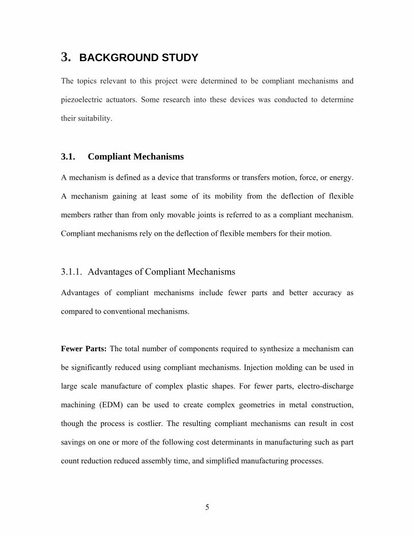
Fewer Parts: The total number of components required to synthesize a mechanism can
be significantly reduced using compliant mechanisms. Injection molding can be used in
large scale manufacture of complex plastic shapes. For fewer parts, electro-discharge
machining (EDM) can be used to create complex geometries in metal construction,
though the process is costlier. The resulting compliant mechanisms can result in cost
savings on one or more of the following cost determinants in manufacturing such as part
count reduction reduced assembly time, and simplified manufacturing processes.
6
Increased Accuracy: The use of compliant mechanisms results in fewer, or zero pin and
sliding joints. This results in reduced wear and less need for lubrication. Also backlash
can be reduced or eliminated. Compliant mechanisms store energy and this property can
be used to eliminate the requirement for springs. The increased performance is a result of
one or more of the following: increased precision, increased reliability, reduced wear,
reduced weight, and reduced maintenance.
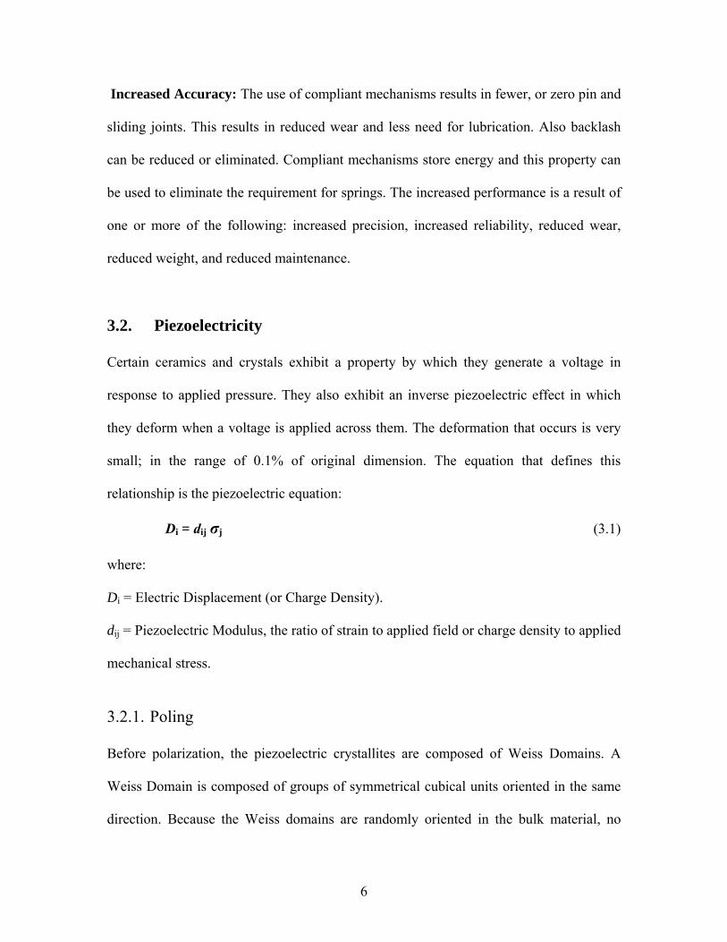
3.2. Piezoelectricity
Certain ceramics and crystals exhibit a property by which they generate a voltage in
response to applied pressure. They also exhibit an inverse piezoelectric effect in which
they deform when a voltage is applied across them. The deformation that occurs is very
small; in the range of 0.1% of original dimension. The equation that defines this
relationship is the piezoelectric equation:
Di = dij σj (3.1)
where:
Di = Electric Displacement (or Charge Density).
dij = Piezoelectric Modulus, the ratio of strain to applied field or charge density to applied
mechanical stress.
3.2.1. Poling Before polarization, the piezoelectric crystallites are composed of Weiss Domains. A
Weiss Domain is composed of groups of symmetrical cubical units oriented in the same
direction. Because the Weiss domains are randomly oriented in the bulk material, no
7
macroscopic piezoelectric behavior is observed. By applying a strong electric field to the
material, these differently oriented Weiss Domains can be aligned because of the
ferromagnetic nature of the material. This is called poling. After the electric field is
removed, a readjustment of the domains causes a reduction in the effective piezoelectric
strength. On a macroscopic scale the ceramic still exhibits a piezoelectric effect wherein
it responds to an electric stimulus by structural deformation.
3.2.2. Piezoelectric Properties In piezoelectric materials’ dielectric constant varies with mechanical load and young's
modulus varies with electrical load. Piezoelectric ceramics are anisotropic in nature i.e.
the piezoelectric effects are dependent on direction. Piezoelectric materials are
characterized by several coefficients. Some of them are strain coefficients, voltage
coefficients, and coupling coefficients. The coefficients give the relationship between
various parameters governing the working of the piezo actuators.
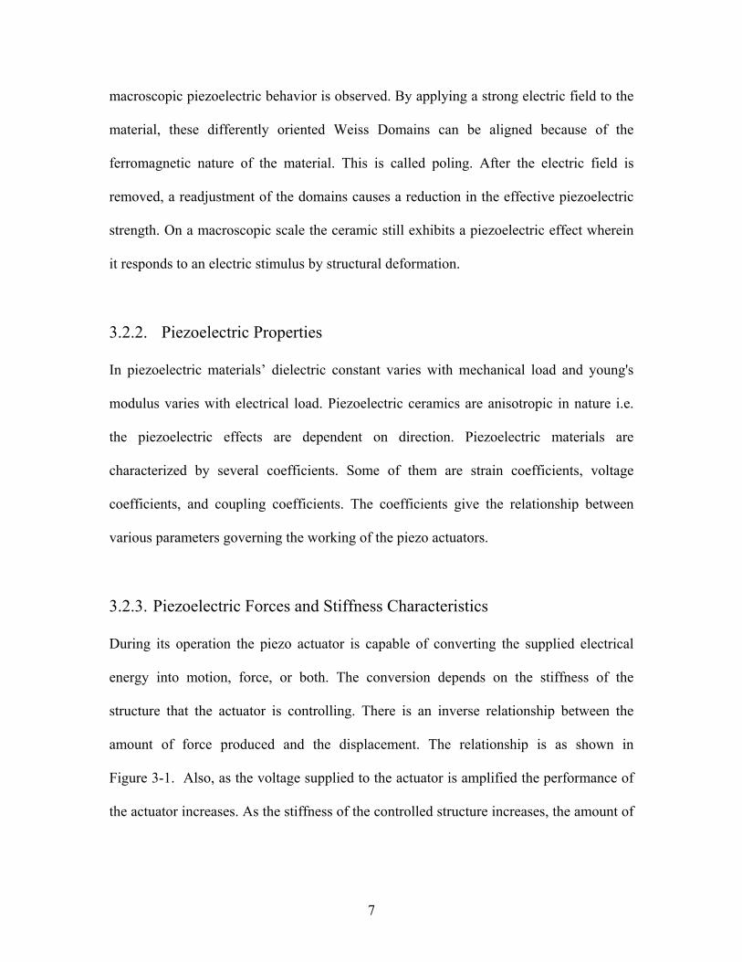
3.2.3. Piezoelectric Forces and Stiffness Characteristics During its operation the piezo actuator is capable of converting the supplied electrical
energy into motion, force, or both. The conversion depends on the stiffness of the
structure that the actuator is controlling. There is an inverse relationship between the
amount of force produced and the displacement. The relationship is as shown in
Figure 3-1. Also, as the voltage supplied to the actuator is amplified the performance of
the actuator increases. As the stiffness of the controlled structure increases, the amount of

8
available displacement decreases with a corresponding rise in the amount of available
force.
Figure 3-1: Force generation vs. displacement of a piezo actuator. Stiffness at various operating voltages. After www.physikinstrumente.com
In Figure 3-1, points where the dashed lines intersect the piezo actuator
force/displacement curves (such as A and B) determine the force and displacement for a
given setup with an external spring. The stiffer the external spring, the less the
displacement and the greater the force generated by the actuator (Point A). Maximum
work can be done when the stiffness of the piezo actuator and external spring are
identical. Also, the stiffness depends on the level of the signal applied across the piezo
terminals. Figure 3-2 indicates that the stiffness of the actuator decreases as the level
(Small/Large) of voltage applied to the actuator is increased.

9
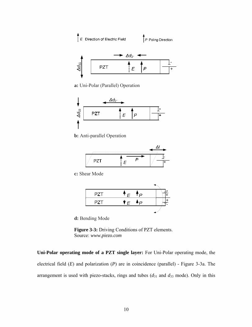
3.2.4. Driving conditions of PZT-elements Figure 3-3 shows the typical operating conditions of PZT ceramics with regard to the
driving electrical field E and ceramics polarization P. Source: www.piezo.com
Figure 3-2: Quasi-static characteristic mechanical stress/strain curves for piezo ceramic actuators and the derived stiffness values. Source: www.physikinstrumente.com
10
a: Uni-Polar (Parallel) Operation
Δd 3
3
b: Anti-parallel Operation
c: Shear Mode
d: Bending Mode Figure 3-3: Driving Conditions of PZT elements. Source: www.piezo.com
Uni-Polar operating mode of a PZT single layer: For Uni-Polar operating mode, the
electrical field (E) and polarization (P) are in coincidence (parallel) - Figure 3-3a. The
arrangement is used with piezo-stacks, rings and tubes (d31 and d33 mode). Only in this

11
mode, can the maximum driving voltages be applied without risk. The allowable voltage
is limited only by the electrical insulation stability of the elements.
The piezomechanical reactions of a uni-polar operated layer are:
a. The layer thickness increases (e.g. multilayer stacks expand). This is called the d33
effect.
b. The cross section of the layer shrinks (e.g. the length of a piezo strip contracts)
(d31 effect) with increasing voltage / field strength (E). This is called the d31 effect.
Anti-Parallel Operation of a single PZT layer: The anti-parallel operation mode occurs
when the driving voltage polarity and thereby the direction of the electrical field (E) is
reversed (Figure 3-3b). The motion characteristic is therefore reversed.
a. d33: the layer thickness decreases with increasing voltage: a multilayer stack shrinks.
b. d31: the diameter of the layer expands
The limitations operating in this mode are:
a. A too-high electrical counter-field (E) can de-pole the actuator structure.
b. It is necessary to stay within the specified voltage ranges
c. Attention has to be given to superposition of other de-poling effects like temperature,
very high loads
Semi-bipolar operation or PZT-components is used to increase the total stroke / blocking
force of ring- and stack- actuators and PZT-tubes. Bipolar operation allows simple
driving electronics to generate bidirectional vibrations. Examples of semi-bipolar and
symmetric bipolar operation are Ultrasonic devices, Scanner tubes, Stacks, rings.

12
Shear Mode: A shear mode PZT layer is based on an in-plane polarization (P). Upon the
application of an electrical field perpendicular to P, a shear motion of the layer occurs,
characterized by the piezo-electric constant d13. Refer Figure 3-3c. Operating in this
mode, a strong electrical field (E) can switch the poling vector (P) irreversibly out of
plane parallel to the applied electrical field. The shear mode is then irreversibly destroyed.
Bending Mode: Piezo-benders are piezo-components consisting of one or more
laminated PZT layers as shown in Figure 3-3d. These layers are operated with different
strain rates resulting in a bending motion of the structure. In the simplest case such a
bimorph bender is activated by a bi-polar signal. Piezo-benders (bimorphs) can be
operated without de-poling risk by using the electrical preload activation technique.
3.2.5. Piezoelectric Actuators Depending on the orientation of its electric field in relation to the poling axis and the
geometry of the piezoelectric crystal, the maximum strain is induced in a particular
direction. Using these characteristics, various types of actuators have been designed for
specific requirements. The piezo actuators are also categorized depending on their
construction as follows:
Stack Actuators: If the electric field is applied along the poling axis then the maximum
displacement of the actuator occurs along the poling axis. These are the most common
type of piezo actuators and can generate the highest forces. The range of displacement
available varies from a few microns to a maximum of about 500 microns. The
13
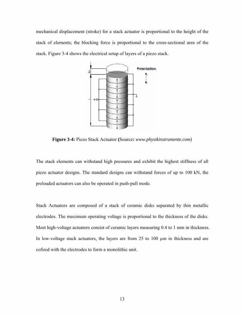
mechanical displacement (stroke) for a stack actuator is proportional to the height of the
stack of elements; the blocking force is proportional to the cross-sectional area of the
stack. Figure 3-4 shows the electrical setup of layers of a piezo stack.
Figure 3-4: Piezo Stack Actuator (Source: www.physikinstrumente.com)
The stack elements can withstand high pressures and exhibit the highest stiffness of all
piezo actuator designs. The standard designs can withstand forces of up to 100 kN, the
preloaded actuators can also be operated in push-pull mode.
Stack Actuators are composed of a stack of ceramic disks separated by thin metallic
electrodes. The maximum operating voltage is proportional to the thickness of the disks.
Most high-voltage actuators consist of ceramic layers measuring 0.4 to 1 mm in thickness.
In low-voltage stack actuators, the layers are from 25 to 100 µm in thickness and are
cofired with the electrodes to form a monolithic unit.

14
Piezo Tube Actuators: The monolithic ceramic tubes are another form of piezo actuator.
Tubes are silvered inside and out, and operate on the transverse piezo effect. When an
electric voltage is applied between the outer and inner diameter of a thin-walled tube, the
tube contracts axially and radially. These exploit the radial contraction direction in
applications such as scanning electron microscopes and micro pumps.
Bender Actuators (Unimorph and Bi-Morph): A simple bender actuator (unimorph
design) consists of a passive metal substrate glued to a piezoceramic strip. (Figure 3-5).
Figure 3-5: Unimorph Design
When the ceramic is energized, it contracts or expands proportional to the applied voltage.
Since the metal substrate does not change its length, a deflection proportional to the
applied voltage occurs. The bimorph design amplifies the dimension change of the piezo,
providing motion up to several millimeters in an extremely small package.
Shear Elements: The active material in the laminar actuators consists of thin, laminated
ceramic strips. The direction of displacement is perpendicular to the direction of
polarization and applied electric field. The contraction coefficient of the element is a
function of the applied voltage and piezo strain coefficient d31.
15
3.3. Damping Techniques In modern product development the design is dynamically stabilized to operating
conditions through tests and adjustments. At times an unknown or unconsidered
parameter, variability in production or negligence, can cause a structure to have a high
level of dynamic response under normal operating conditions. Drastic changes to a design
are not practical at the very final stages of product development. In such cases, the
resulting vibrations are reduced using various techniques. Some of those techniques are
absorption, structural damping, isolation, or use of barriers and enclosures. Though
principles behind some of them overlap, in application, they considerably reduce the
undesired dynamic activity of the structure.
In absorption technique, the aim is to absorb the vibrations directly. A spring, a hydraulic,
pneumatic or a similar device is introduced between the source of vibration and the
structure. In case of enclosure, a physical barrier is introduced between the source of
vibration and the structure. Isolation techniques are again similar to absorption techniques
but differ mostly in their application.
The structural damping technique is used to reduce noise and vibrations caused by both
impacts and steady state excitations. In this technique, the structure is treated with one or
a combination of materials, to increase its ability to dissipate mechanical energy. It is
most effective when the operation of a structure is near one of its resonant frequencies
and involves a large spectrum of frequencies introduced either due to impacts, transient
forces, transmission or a combination of them.

16
3.3.1. Free Layer or Extension Damping This is one of the simplest structural damping techniques. A viscoelastic damping
material is attached to the structure using a strong bonding agent. Viscoelastic materials
can store strain energy when deformed and dissipate a portion of energy through
hysteresis, which results in transforming the mechanical energy to heat energy
(Figure 3-6). Energy dissipation occurs due to flexural stress introduced in the damping
material from the base structure causing extension and compression of damping material.
The composition and thickness of the damping material are the governing parameters for
the effectiveness of damping.
Figure 3-6: Energy is dissipated as result of extension and compression of the material under flexural stress from the base structure. Source: Jennifer Renninger, EARSC.

17
3.3.2. Constrained Layer Damping Constrained layer damping is one of the structural damping techniques used for very stiff
structures. In this technique, a constraining layer is added along with a damping layer
over the surface of the structure whose vibrations are to be controlled (Figure 3-7).The
shear deformations in the damping material result in energy dissipation.
Figure 3-7: Constrained-layer damping. Energy is dissipated as a result of shear deformation of the damping layer. (Source: Jennifer Renninger, EARSC)
3.4. Literature review
Extensive literature review was done to understand the application and working of
compliant mechanisms, piezo actuators, amplifying mechanisms, and a combination of
them. The review involved reading the text “Compliant Mechanisms” by Larry Howell,
“Design of Machinery, an introduction to Synthesis and Analysis of Mechanisms and
Machines, by R. L. Norton, and the Nanopositioning Handbook by Physik Instrumente.
The various publications as listed in the bibliography were obtained either through the
World Wide Web or through the WPI library. The literature review helped in refreshing

18
the concepts learned earlier and developing an understanding of new concepts to be
involved in the research.
Sitti, Campolo, Yan and Fearing [1] in 2001 presented the development of PZT and
PZN-PT Based Unimorph Actuators for Micromechanical Flapping Mechanisms. In 2001,
Claeyssen, Letty, Barillot, Lhermet, Fabbro, Guay, Yorck, Bouchilloux [2] described
amplification in piezoelectric mechanisms. They also developed proof of concept XYZ
stage mechanism for a space application. In a paper published in 2002 by Capelleri,
Frecker, Simpson and Snyder [3], design of a PZT bimorph actuator using a metamodel
based approach for application to minimally invasive surgery is discussed.
Ananthasuresh and Howell [4] have put forth the important role of compliant
microsystems involving flexible structures and flexural joints in the future development
of Micro Electro Mechanical Devices (MEMS) in their paper published in 2005. Kota,
Lu, Kreiner, Trease, Arenas, Geiger [5] show the benefits of exploiting elasticity in the
engineering design of surgical tools, in general, and of minimally invasive procedures, in
particular.
Lu and Kota [6] in their paper published in 2003 explain design techniques for creating
structural shape morphing in compliant mechanisms. They have extensively used the
advantages of smooth deformation field obtained using distributed compliance. They also
explored the potential of using such compliant mechanisms to integrate well within the
constraints of laparoscopic procedures and telerobotic surgery

19
Varma and Dixon [7] have demonstrated the use of the combination of piezoelectric
actuators with compliant joints for motion amplification. They were able to amplify the
motion of the piezo by 107 times and used it in a proof of principle prototype of a
Meso-Scale Mobile Robot. Bharti and Flecker [8] and [9] in 2003 proposed motion
amplification using compliant joints and multiple optimally placed actuators. They also
used combinations of compliant mechanisms to amplify motion available through piezo
actuators and demonstrated the same on an inertially stabilized rifle. A 1999 paper by
Canfield and Frecker [10] develops a method for the design of displacement amplifying
compliant mechanisms for piezoelectric actuators using a topology optimization approach.
They considered as objective functions, overall stroke amplification or geometric
advantage of the mechanism, and the overall mechanical efficiency of the mechanism.
In 2005, Abdalla, Frecker, Gurdal, Johnson and Lindner [11] discuss design of a
piezoelectric actuator and compliant mechanism combination for maximum energy
efficiency. Li, Sedaghati, and Dargahi [12] in 2004 presented a proof-of-concept design
of an inchworm type piezoelectric actuator with output of maximum displacement and
force (or power) for shape control and vibration control of adaptive truss structures.
Venanzi, Giesen, and Parenti-Castelli [13] have developed a novel technique for position
analysis of planar compliant mechanisms. They demonstrate an iterative technique to
perform the non-linear analysis of planar rigid-link mechanisms with compliant
kinematic pairs. Their analysis technique, which considers large scale deflections without
approximations of small deflections, is computationally efficient as it does not use finite

20
element methods. Large deformation behavior of compliant mechanisms is presented in
the paper published by Joo, Kota, and Kikuchi [14] in 2001. In this paper they used linear
and non linear techniques for shape optimization in compliant mechanisms using the
example of a stroke amplification mechanism. Kim, Kota and Moon [15] present the use
of an instant center approach to the conceptual design of compliant mechanisms. Li and
Kota [16] present a systematic method for dynamic analysis of compliant mechanisms
including basic formulations for natural frequencies, modes, dynamic response, and
frequency characteristics. They demonstrate a method for design sensitivity analysis
investigating the effect of various design parameters on the dynamic performance of
compliant mechanisms using an example of a MEMS actuator.
Qinga, Chana, Bearda, Ooib, and Marotta [17] in 2005 show the effect of adhesive on
the performance of piezoelectric elements used to monitor structural health. The
experimental studies performed by them revealed that an increase in adhesive thickness
alters the electromechanical impedance and the resonant frequency of the piezoelectric
elements as well as the amplitude of the sensor signal. When the elastic modulus of
elasticity is within a certain range, the elastic modulus of adhesive slightly affects the
impedance of PZT element and the amplitude of sensor signal at lower frequency, while
at high frequency, the impedance response and sensor signal are more sensitive to the
elastic modulus of adhesive.

21
4. DESIGN CONCEPTS
This section describes the development of conceptual mechanisms to satisfy the project
objectives. Concepts were generated using two types of piezo actuators and compliant
mechanisms. Linkage mechanisms were developed to understand the geometries required
in motion amplification and later used in development of conceptual compliant
mechanisms.
4.1. Concept 1 A piezo bender was used in this concept (Figure 4-1). The bender actuator can provide a
end deflection up to 1.6 mm. This deflection was used to displace a follower which
would engage with parts. The mechanism needed preloading to provide the return motion
else bimorph actuator would have been used.
Piezo Bender Actuator
Point of Escapement
Return Spring
h
Figure 4-1: Layout of Concept 1
22
The bender actuator is clamped at one end and is free at the other end. When voltage is
applied across the terminals of the actuator, it bends causing the tip to achieve a height; h.
The height h depends on the maximum nominal displacement for the bender actuator and
the resistance the system including the spring offers to the return motion. Also, the
vertical component of reactive force by the parts to be escaped will reduce the total tip
displacement.
Advantages: The design is compact, simple, and economic. Therefore the required
modification for the system will be minimal.
Limitation: The force requirement of the spring may exceed the actuator’s nominal force.
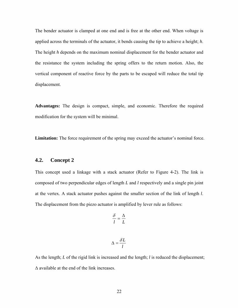
4.2. Concept 2 This concept used a linkage with a stack actuator (Refer to Figure 4-2). The link is
composed of two perpendicular edges of length L and l respectively and a single pin joint
at the vertex. A stack actuator pushes against the smaller section of the link of length l.
The displacement from the piezo actuator is amplified by lever rule as follows:
LlΔ
=δ
Llδ
Δ =
As the length; L of the rigid link is increased and the length; l is reduced the displacement;
Δ available at the end of the link increases.
23
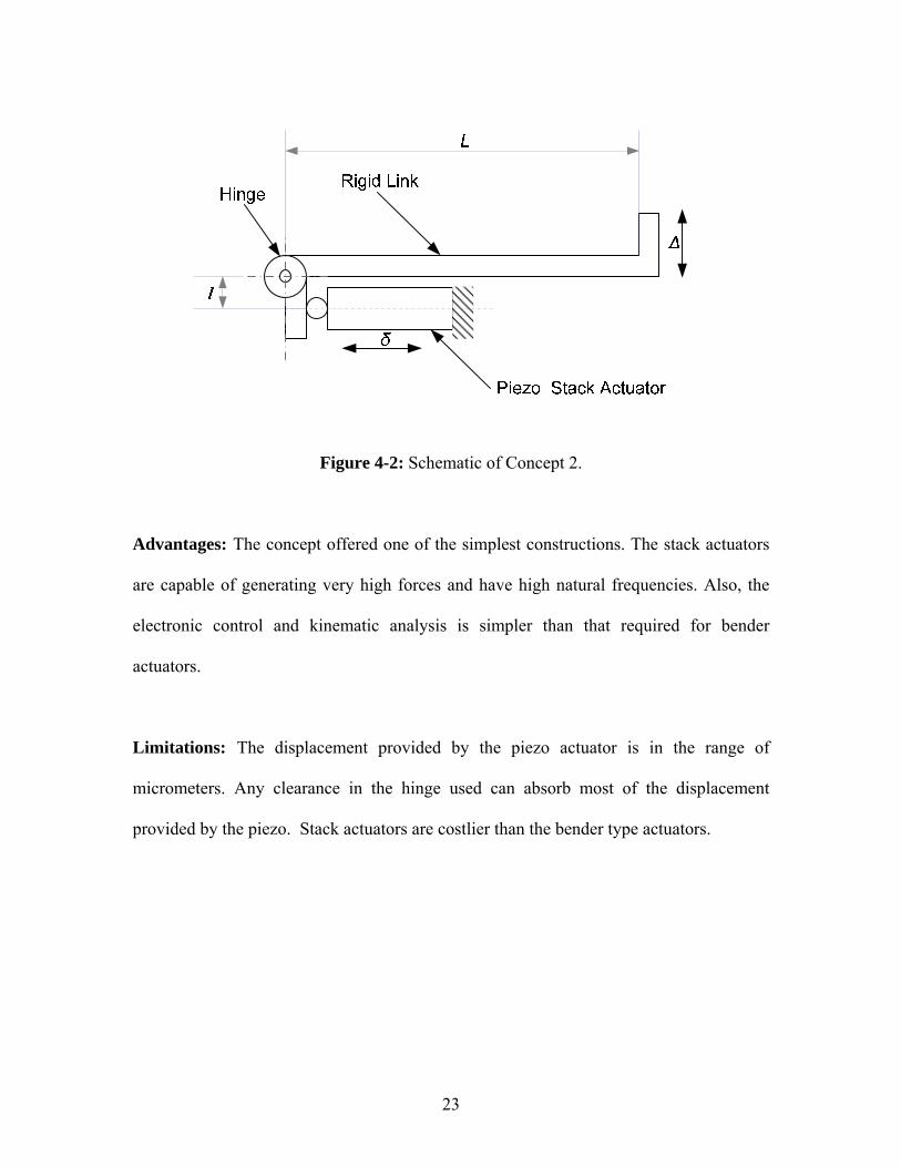
Figure 4-2: Schematic of Concept 2.
Advantages: The concept offered one of the simplest constructions. The stack actuators
are capable of generating very high forces and have high natural frequencies. Also, the
electronic control and kinematic analysis is simpler than that required for bender
actuators.
Limitations: The displacement provided by the piezo actuator is in the range of
micrometers. Any clearance in the hinge used can absorb most of the displacement
provided by the piezo. Stack actuators are costlier than the bender type actuators.

24
4.3. Concept 3 In these concepts, linkage based mechanisms were developed with a high geometric
advantage. Figure 4-3a shows a symmetric four bar mechanism in conjunction with a
piezoelectric actuator. As the height h of the coupler is increased, the tip gets farther from
the instantaneous center of rotation I, and this results in larger motion amplification. Also,
for achieving larger motion amplification, the piezo actuator has to be placed nearest to
pin joint 1. Figure 4-3b shows another linkage based mechanism that could be used for
motion amplification. Here, the amplification is achieved along two directions. The
relative positions of pin joints govern available amplification.
Piezo Stack Actuator
Point of Escapement
I
hCoupler
Instantaneous Center of Rotatation
1
2 3
4
a): Schematic of Concept 3a
b): Schematic of Concept 3b
Figure 4-3: Fourbar Linkage Concepts
Advantages: The two linkage-based mechanisms shown are kinematically simple. The
mechanisms have very large displacement amplification.
25
Limitations: As in concept 2, most of the micrometer displacement provided by the
piezo actuator will be absorbed by the clearances in the pin joints.
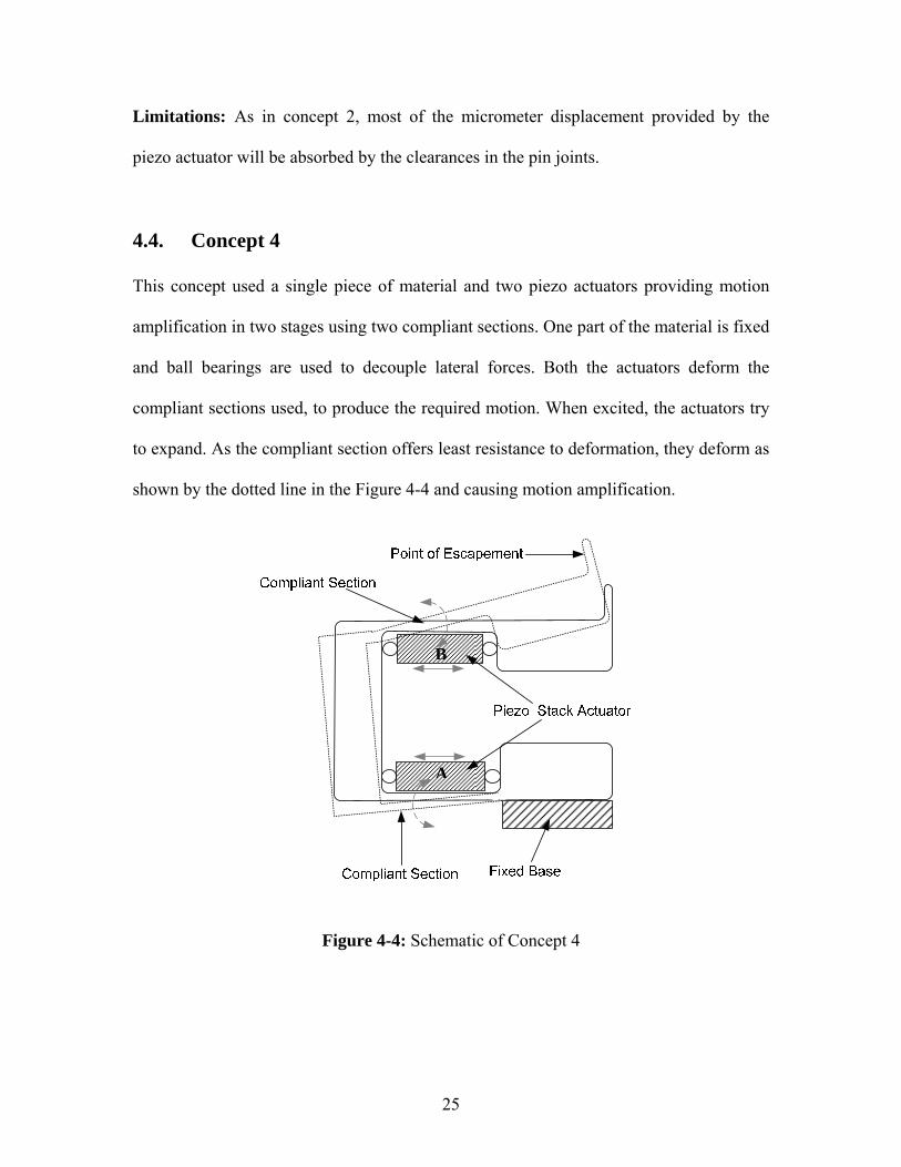
4.4. Concept 4 This concept used a single piece of material and two piezo actuators providing motion
amplification in two stages using two compliant sections. One part of the material is fixed
and ball bearings are used to decouple lateral forces. Both the actuators deform the
compliant sections used, to produce the required motion. When excited, the actuators try
to expand. As the compliant section offers least resistance to deformation, they deform as
shown by the dotted line in the Figure 4-4 and causing motion amplification.
Figure 4-4: Schematic of Concept 4
A
B

26
Advantages: The concept is simple in construction. It is composed of only three
functional components, the block of material with a compliant section and two
piezoelectric stack actuators.
Limitations: The two actuators may lead to a costly solution. Also, the manufacturability
of the single piece is difficult and would require very high costs.
27
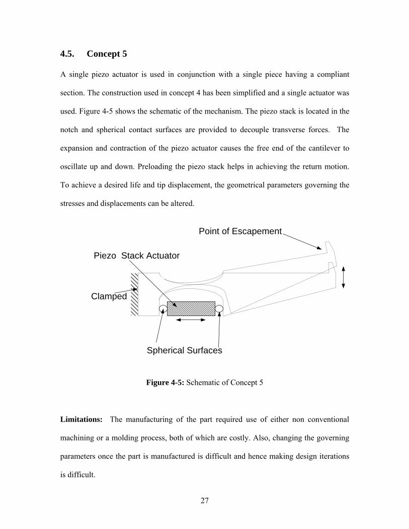
4.5. Concept 5 A single piezo actuator is used in conjunction with a single piece having a compliant
section. The construction used in concept 4 has been simplified and a single actuator was
used. Figure 4-5 shows the schematic of the mechanism. The piezo stack is located in the
notch and spherical contact surfaces are provided to decouple transverse forces. The
expansion and contraction of the piezo actuator causes the free end of the cantilever to
oscillate up and down. Preloading the piezo stack helps in achieving the return motion.
To achieve a desired life and tip displacement, the geometrical parameters governing the
stresses and displacements can be altered.
Point of Escapement
Piezo Stack Actuator
Spherical Surfaces
Clamped
Figure 4-5: Schematic of Concept 5
Limitations: The manufacturing of the part required use of either non conventional
machining or a molding process, both of which are costly. Also, changing the governing
parameters once the part is manufactured is difficult and hence making design iterations
is difficult.

28
4.6. Concept 6 Concept 6 simplifies concept 5. The complex geometry of the single piece is broken
down into separate parts resulting in better manufacturability. This design is easy to
prototype and the governing parameters required for maximizing the displacement such
as the length of the compliant section can be easily modified.
Figure 4-6: Schematic of Concept 6
Advantages: For a given deflection, the level of stress is reduced as the thickness of the
compliant section is reduced. The use of distributed compliance reduces stress
concentrations, allowing long life. The manufacturing of all the components can be done
using conventional machining techniques.
Limitations: The number of components including fasteners used in the design is large.
4.7. Concept Selection After various alternative conceptual designs were generated, a qualitative evaluation was
done. The criteria were selected for prototyping purposes and can be changed for mass
production.

29
Table 4-1 shows an evaluation matrix. The first row lists the factors being evaluated. The
next row gives the relative importance of factors for a successful make of a prototype.
The importance is rated on a scale of 1-10. In the following rows the concepts are scored
for the characteristics they exhibit for a particular factor. The scores are graded on a scale
of 0-5. The final column gives the total score for a particular concept based on the
scoring discussed above.
Concepts 5 and 6 have the highest scores. Concept 6 was selected for prototyping as it
was easier to manufacture and allowed the governing kinematic parameters to be altered
after construction.
Table 4-1: Concept Selection Matrix
Fact
ors E
valu
ated
Tot
al C
ost
Mec
hani
sm L
ife
Com
plex
ity
Con
trol
Com
plex
Cus
tom
Par
ts
Num
ber
of P
in J
oint
s
Eas
e of
Ass
embl
y
Scor
e Importance 10 10 7 5 5 8 3 3
Concept 1 3 3 4 2 2 5 3 157
Concept 2 4 4 4 4 3 3 5 182
Concept 3a 3 4 3 4 4 1 3 148
Concept 3b 3 4 2 4 4 0 2 130
Concept 4 2 5 4 4 2 5 5 183
Concept 5 3 5 4 4 2 5 5 193
Concept 6 4 5 3 4 4 5 4 203

30
5. DETAILED DESIGN The chapter describes the derivation of critical dimensions of the mechanism for the
stroke and dynamic requirements.
5.1. Design Specifications The mechanism should be able to demonstrate parts escapement at a desired high
frequency. The escapement rate to be achieved using the test bed is 10 parts per second
with at least 0.5 mm of displacement available for escapement. During the operation, the
mechanism should be dynamically stable and should not interfere with other auxiliary or
main mechanisms. The mechanism should be compact as compared to existing assembly
line. A space envelope 200 mm X 150 mm X 100 mm was taken as appropriate. Also, the
design should be adaptable to the existing assembly lines or be incorporated in design of
new assembly lines.
5.2. Motion Analysis A motion equation was derived and used to perform iterations. The study of various
mechanism parameters on the tip displacement and the first natural frequency using a
lumped mass model was done. The critical parameters considered were the width,
thickness, and length of the compliant spring steel section, length of the relatively rigid
section of the cantilever, and the specifications of the piezo actuator and amplifier. The
studies, in conjunction with material availability were used in finalizing the dimensions.
Additional changes to some of the critical parameters were done to account for
experimental observations.

31
The mechanism is composed of two beam sections as shown in Fig 5-1. The first section
is a compliant section of length L1. The second section is a relatively rigid section of
length L2. The deformation of the piezo actuator introduces an axial tensile force and an
anticlockwise bending moment in the compliant section. As the beam is stiff in the axial
direction, the axial deformation is neglected and only the effect of bending moment is
considered in further analysis. The bending moment causes the compliant section to
curve. The rigid section attached at the end tilts upwards with a slope equal to that of the
tip of the compliant section.
Figure 5-1: The Selected Concept.
The compliant section is made of a spring steel strip. The piezo actuator is placed in
relation to the compliant section as shown in Figure 5-1. The resisting force offered by
the cantilever to the piezo displacement creates a moment at the free end that causes the
compliant section to bend. The axial elongation of the beam is negligible.
The moment generated at the free end of the beam is given by M.
M F d= (5.1)
Where, F and d are as shown in Figure 5-2. The other parameters used in analysis are
shown in Figure 5-3.

32
The moment causes the free end (at length L1) to deflect in the positive y direction by
21
1
1 1
2 2
2
2
M LE I
LL
δ
δδ
−=
=
(5.2)
Where,
E = Young’s modulus of the compliant section
I = the area moment of inertia
Figure 5-2: Variables used in analysis of selected concept.
Figure 5-3: Variables used in analysis of selected concept.
The slope of the deflected beam at the free end is given by θ .
1M LE I
θ−
= (5.3)

33
The deflection at the free end of the rigid section relative to the free end of the compliant
section (at length L1) is given by
1 22 2
M L LE I
δ−
= (5.4)
The total deflection available at the free end of the rigid section is given by the equation
21
total 1 22LM L L
E Iδ
⎡ ⎤−= +⎢ ⎥
⎢ ⎥⎣ ⎦ (5.5)
5.3. Vibration Analysis
The dynamic behavior prediction was done for the mechanism. The mechanism was
considered to be a cantilever beam with a point mass at the free end of the cantilever. The
point mass considered was equivalent to masses of rigid section of the cantilever, ball
bearing, block holding the ball bearing, hardware and compliant section of cantilever.
The spring stiffness was found for the compliant section and using that the natural
frequency of the mechanism was calculated.
The stiffness of the compliant section was found using the following equation:
3
3E IkL
= (5.6)
Where,
k = Stiffness of the compliant section (N/m)
E = Modulus of Elasticity of the compliant section (spring steel) (N/m2)
I = Moment of Inertia of the compliant section along x-x axis (m4)

34
3
12w tI = (5.7)
Where,
w = width of the compliant section (m)
t = thickness of the compliant section (m)
L = Length of the compliant section (m)
The natural frequency of the mechanism was estimated using the following equation:
12n
kfmπ
= (5.8)
Where, m is the total mass acting at the free end of the cantilever.
The effect of various design parameters controlling the natural frequency of the
mechanism was studied. Natural frequency was estimated for different materials that
could be used to build the rigid section of the cantilever. The natural frequency of the
mechanism was estimated for various thicknesses, widths, and lengths of compliant
section of cantilever.
5.4. Parameter Effects
The equations derived in sections 5.5 and 5.8 were used to study the effect of certain
dimensions on displacement and natural frequency of the mechanism. The study was
done by varying a single parameter at a time. The results obtained from the study were
used in choosing and justifying the selected dimensions. Also, they will be useful in
35
making changes to the dimensions for improving the performance of the mechanism to
the desired levels.
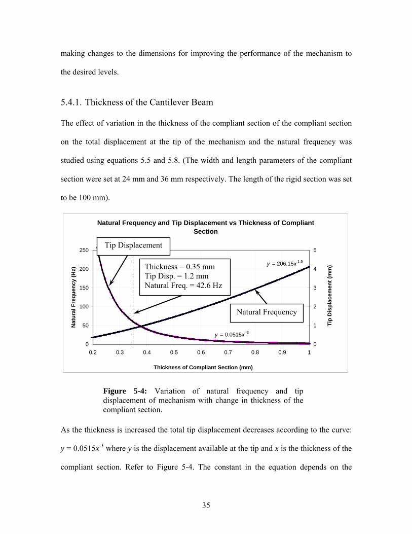
5.4.1. Thickness of the Cantilever Beam The effect of variation in the thickness of the compliant section of the compliant section
on the total displacement at the tip of the mechanism and the natural frequency was
studied using equations 5.5 and 5.8. (The width and length parameters of the compliant
section were set at 24 mm and 36 mm respectively. The length of the rigid section was set
to be 100 mm).
Natural Frequency and Tip Displacement vs Thickness of Compliant Section
y = 0.0515x -3
y = 206.15x 1.5
0
50
100
150
200
250
0.2 0.3 0.4 0.5 0.6 0.7 0.8 0.9 1
Thickness of Compliant Section (mm)
Nat
ural
Fre
quen
cy (H
z)
0
1
2
3
4
5
Tip
Dis
plac
emen
t (m
m)
Figure 5-4: Variation of natural frequency and tip displacement of mechanism with change in thickness of the compliant section.
As the thickness is increased the total tip displacement decreases according to the curve:
y = 0.0515x-3 where y is the displacement available at the tip and x is the thickness of the
compliant section. Refer to Figure 5-4. The constant in the equation depends on the
Tip Displacement
Natural Frequency
Thickness = 0.35 mm Tip Disp. = 1.2 mm Natural Freq. = 42.6 Hz

36
material, width, and length of the complaint section. The natural frequency of the
mechanism increases with an increase in thickness of the compliant section according to
y = 206.15x1.5 , where y is the natural frequency of the mechanism.
5.4.2. Width of the Cantilever Beam Figure 5-4 shows the effect of variation in the width of the compliant section to the tip
displacement available and the natural frequency of the mechanism. Equations 5.5 and
5.8 were used to determine the shown behavior. The tip displacement is inversely
proportional to the width of the compliant section and natural frequency is proportional to
the square root of the width. (The thickness and length parameters of the compliant
section were set at 0.35 mm and 36 mm respectively).
Natural Frequency and Tip Displacement vs Width of Compliant Section
y = 8.7131x 0.5
y = 28.817x -1
0
10
20
30
40
50
60
70
0 10 20 30 40 50
Width (mm)
Nat
ural
Fre
quen
cy (H
z)
0.0
0.5
1.0
1.5
2.0
2.5
3.0
3.5
4.0
4.5
5.0
Tip
Dis
plac
emen
t (m
m)
Figure 5-5: Variation of natural frequency and tip displacement of mechanism with change in width of the compliant section.
Tip Displacement
Natural Frequency
Width = 24 mm Tip Disp. = 1.2 mm Natural Freq. = 42.6 Hz

37
5.4.3. Lengths of the compliant and rigid section: To study the variation in tip displacement of the mechanism with variation in the lengths
of the compliant and rigid section of the cantilever, equation 5.5 for the total tip
displacement was used. The ME I− term was assumed as unity and the lengths L1 and L2
were varied one at a time to see their effects on the total tip displacement. Figure 5-5
shows that the tip displacement is more responsive to variation in the length of the
compliant section.
Length vs Tip Displacement (Normalised)
0
0.1
0.2
0.3
0.4
0.5
0.6
0.7
0.8
0.9
1
0 0.2 0.4 0.6 0.8 1
Normalised Length
Nor
mal
ised
Tip
Dis
plac
emen
t
Figure 5-6: Variation of tip displacement with lengths of compliant and rigid sections of the cantilever.
5.4.4. Material for Rigid Part of the Cantilever Beam
The dynamic components used in the mechanism were the compliant section of the
cantilever, the rigid section of the cantilever, and the hardware. The only material option
L1 = Varied (0 – 1) L2 = Constant (0.3)
L1 = Constant (0.3) L2 = Varied (0 – 1)

38
for the compliant section of the cantilever was the spring steel strip. Three different
materials, plastic, aluminum, and steel were evaluated for their effect on the natural
frequency of the mechanism. Table 5-1 gives the summary of results.
Table 5-1: Natural Frequency variation with material of Rigid Section
Mass (kilograms)
Plastic Aluminum Steel 0.0159 0.0277 0.0608
Moment of Inertia (bh3)/12 m4 8.575 X 10⁻¹⁴ 8.575 X 10⁻¹⁴ 8.58 X 10⁻¹⁴
Length of spring steel m 0.036 0.036 0.036
Modulus of Elasticity N/m2 2.07 X 10¹¹ 2.07 X 10¹¹ 2.07 X 10¹¹
Spring constant 3EI / L3
m4 1.14 X 10³ 1.14 X 10³ 1.14 X 10³
Natural Frequency ωn = (k/m)1/2 rad/sec 268.20 202.70 136.93
Natural Frequency Hz 42.68 32.26 21.79
For a structure to be dynamically stable, its first natural frequency should be at least three
times that of the frequency at which it is required to operate. The minimum operating
frequency desired for the mechanism is 10 Hz. This will require the natural frequency of
the mechanism to be greater than or equal to 30 Hz. Using steel for the rigid section of
the beam, the requirement cannot be achieved, and with aluminum we will be operating
very close to the desired limit. Plastic gives a natural frequency of 42 Hz, which is well
above the requirement and was selected as a material for the rigid section of the
cantilever. Also, it is easier to machine.
39
5.5. Design Parameters Selected COMPLIANT MECHANISM DESIGN
Using the predicted behavior of the mechanism from the equations developed earlier,
parameters were selected for the final design. It was observed that as the thickness and
the width of the compliant section were reduced, tip displacement increased and natural
frequency of the mechanism decreased. The reverse happened with the length of the
compliant section. As the length of the compliant section was decreased, tip displacement
decreased and natural frequency increased.
The mechanism is required to have a tip displacement of at least 0.5 mm and an operating
frequency of 10 Hz. These requirements can be realized by selecting appropriate values
for the governing parameters. An operating frequency of 10 Hz requires a minimum
natural frequency of 30 Hz for dynamically stable operation. The redefined requirements
of the mechanism were written as a minimum tip displacement of 0.5 mm and a natural
frequency of 30 Hz. These values could be achieved by changing the three governing
parameters, thickness, width, and the length of the compliant section in different ways.
Iterations were performed by varying a single parameter at a time and the results were
used to justify the selected dimensions.
While performing initial design iterations, it was assumed that the length of the
piezo-electric actuator equals the length of the compliant section of the cantilever. Also,
the total length of the cantilever including the rigid section was constrained to 100 mm.
These constraints were used in iterations of the parameters in equation 5.5. This resulted

40
in selecting the length of the actuator and the compliant section to be 35 mm and the rigid
section to be 75 mm.
An available, AST 1095, full hard, spring steel strip of 24 mm X 0.35 mm cross section
was evaluated for required tip displacement and natural frequency. The results showed
that tip displacement available with these dimensions was 1.2 mm and the natural
frequency was 42.69 Hz. These results satisfied the requirements for the prototype and so
the available spring steel section was selected to be used on the prototype.
In the future if it is required to have a larger tip displacement, the thickness and/or the
width of the cross section can be reduced, but this will also lower the operating frequency.
On the other hand, if it is required to have a higher operating frequency, the thickness
and/or the width of the cross section can be increased, but this will also result in smaller
tip displacement. Also, it was later realized that the length of the compliant section was
independent of length of the piezo stack. This makes possible to achieve the required tip
displacement or the natural frequency by changing the length of the compliant section.
A better dynamic performance of the mechanism can be achieved for the same required
tip displacement by eliminating the relatively rigid section of cantilever. The length of
compliant section has larger positive effect on the end displacement and the natural
frequency of the mechanism than the relatively rigid section of the cantilever.

41
PIEZO SELECTION
Various piezo stacks available in the market were benchmarked and compared. The
piezoelectric actuator selected was 36 mm long model P-885.90, made by Physik
Instrumente. It has a maximum displacement of 36 μm. It is a ceramic-encapsulated, high
performance monolithic, multilayer piezo actuator. Table 5-2 gives the specifications of
the actuator and Figure 5-7 shows a picture of actuator used.
Table 5-2: Specifications of the piezo actuator selected for the research.
Dimensions AxBxL
Nominal Displacement
Max. Displacement
Blocking Force Stiffness
Electrical Capacitance
Resonant Frequency
[mm] [μm @ 100V] [μm @120 V] [N @ 100 V] [N/μm] [μF] [kHz]
(±10%) (±10%) (±20%) 5 X 5 X 36 30 35 900 28 3.1 40
Figure 5-7: Piezo Stack Actuator used for the research(P-885.90)
The piezo actuator undergoes maximum nominal displacement at a voltage of 120 V. The
function generator used, has voltage output in the range of 0-10 V and the Dynamic
Signal Analyzer has voltage output in the range of 0-5 V. The waveforms generated using
these devices need amplification before being fed to the actuator. Therefore a voltage
signal amplifying device was required to amplify the signal output from the waveform
generating devices used.
42
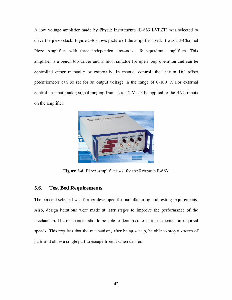
A low voltage amplifier made by Physik Instrumente (E-663 LVPZT) was selected to
drive the piezo stack. Figure 5-8 shows picture of the amplifier used. It was a 3-Channel
Piezo Amplifier, with three independent low-noise, four-quadrant amplifiers. This
amplifier is a bench-top driver and is most suitable for open loop operation and can be
controlled either manually or externally. In manual control, the 10-turn DC offset
potentiometer can be set for an output voltage in the range of 0-100 V. For external
control an input analog signal ranging from -2 to 12 V can be applied to the BNC inputs
on the amplifier.
Figure 5-8: Piezo Amplifier used for the Research E-663.
5.6. Test Bed Requirements The concept selected was further developed for manufacturing and testing requirements.
Also, design iterations were made at later stages to improve the performance of the
mechanism. The mechanism should be able to demonstrate parts escapement at required
speeds. This requires that the mechanism, after being set up, be able to stop a stream of
parts and allow a single part to escape from it when desired.

43
5.6.1. Set-up Requirements The design had to allow parts to be fed to the mechanism at a higher rate than that of the
operating speed. The orientation and feed rate needed to be controllable. One of the
options was to use an aluminum rail through which standard assembly components
available from the sponsor could be fed by blowing pressurized air over them. This
replicates part-feeding in the actual assembly line. However it would be complicated for
this proof-of-concept exercise. It was decided to use simple parts that can be more easily
fed to the mechanism.
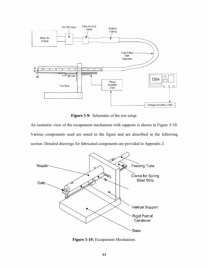
5.7. Test Bed Description Figure 5-9 shows a schematic arrangement of the test bed. The pressure and flow rate of
shop air supply is controlled using the On-Off Valve and the Flow Control Valve. A
flexible rubber tubing section provides for ease of connection of the air supply with the
tube used to feed capsules to the mechanism. The escapement mechanism is supported by
proper supports and is constrained on a flat surface. The piezo stack is fed with an
amplified voltage signal from the function generator. Depending on the output of a
specific function generator used, modifications are made to the setup to amplify the
voltage signal to required levels.
44
Figure 5-9: Schematic of the test setup.
An isometric view of the escapement mechanism with supports is shown in Figure 5-10.
Various components used are noted in the figure and are described in the following
section. Detailed drawings for fabricated components are provided in Appendix 2.
Figure 5-10: Escapement Mechanism.

45
Clamp for spring steel strip: The clamp is used to hold the fixed end of the cantilever
beam. Six pairs of nut and bolts are used to rigidly fix the end of the spring steel which is
sandwiched between the clamping pair. The clamps are made of aluminum for ease of
machining. A constraining groove is machined on the surface to provide the alignment.
(Refer to Appendix 2). This provides ease of locating the spring steel strip during
assembly.
Vertical Support: The vertical support is machined out of 1” thick aluminum block. It
supports the clamp at the fixed end.
Base: 1” thick aluminum was used for the base. Its function is to provide an orienting
surface for the Vertical Support.
Capsules - Parts for Escapement: It was decided to feed the parts by blowing them
through a tube. Empty medicine capsules used in the pharmaceutical industry were
chosen as dummy parts. Figure 5-11 shows the picture of the capsule.
Figure 5-11: Capsule
The advantages of using the capsules were their easy availability and their low
dimensional variability. On the other hand, the large spherical radius the capsules have at
the ends caused them to slip over the gate of the mechanism. A sharp edged part would
have been easier to stop. They were selected because they can move easily through the

46
tube and can be driven by air. Shop air was used to feed the capsules to the mechanism.
There are various standard sized capsules available in the market. The size of the
capsules was chosen with consideration to the internal diameter of tubing to be used to
feed them. The capsule size chosen was “00”. The specifications for the same are given
in Table 5-3.
Table 5-3: Specifications of capsule in inches.
Cap Body Length (in) 0.413-0.441 0.713-0.740
Closed Length (in) 0.839-0.862 External Diameter (in) 0.301-0.302 0.289-0.290
Tubing: The tubing was selected considering requirements of low friction and internal
diameter. The tubing is made of Poly Vinylidine Di-Fluoride (PVDF) and has very low
coefficient of friction (in the range of 0.2-0.4). The internal diameter of the tubing is
0.4375”. The internal diameter was selected to provide sufficient clearance for capsules
to pass through and at the same time maintain sufficient air pressure to drive the capsules
forward.
Nozzle: The nozzle is made of aluminum. It provides fixed orientation to the parts
(empty capsules) during escapement. The requirement for a nozzle was determined after
some escapement experiments were performed, as the capsules coming directly out of the
tubing were not in proper orientation with the gate.
Gate: The gate is made of a plastic screw and piece of plastic sheet (Figure 5-12). The
end of the screw was ground flat and a rectangular piece of plastic was glued over it

47
using a cyno-acrylate adhesive. The gate, along with the nozzle, helped in maintaining a
proper orientation of escaping capsules.
Figure 5-12: Modified Gate used to block capsules.
Purchased components: Some of the components required for the fabrication and
testing of the prototype were purchased off the shelf. Appendix 6 lists them.
Figure 5-13 represents the way the capsules were fed to the mechanism. The capsules
first filled in the PVDF tubing are blown by air into nozzle. In the powered state the piezo
actuator causes the cantilever to rise up and hold back capsules at the tip as represented in
Figure 5-13.
Figure 5-13: Front View of the Test Bed. (Tube and Nozzle filled with Capsules)
End of the screw ground flat, to attach a plastic piece.
Rectangular piece of plastic glued to flat
surface of screw

48
In the un-powered state the cantilever moves down, allowing the capsules to escape
through the nozzle. A ball bearing was used between piezo and beam to decouple the
transverse forces from the piezo actuator. The ball bearing rests inside a lexan block. The
block also accommodates a set screw to adjust the ball bearing relative to the piezo
actuator. This can also be used to pre-load the piezo actuator. Figure 5-14 shows pictures
of the mechanism as fabricated and used for testing.
Figure 5-14: Components used in mechanism.

49
5.8. Testing Procedure The PVDF tubing must first be fitted to the nozzle on the test bed as shown in
Figure 5-15.
Figure 5-15: PVDF tubing fitted to the Nozzle on the Test Bed.
The tubing is then filled with capsules from the other end. The larger end of the capsule
must be inserted first into the tubing. This helps avoid jamming of the capsules at the
nozzle-tubing interface. The tube has to be filled with about 70 capsules. Figure 5-16
demonstrates the way to fill the capsules in the tubing.
Figure 5-16: Way to fill the capsules in the tube. Notice that larger end is inserted first.
PVDF Tubing Correct Orientation of Capsule
PVDF Tubing
Nozzle
Clamp
Gate

50
After filling the tube with capsules, the air supply to the tubing has to be arranged. The
needle valve and spare tubing are connected with the air outlet used for pneumatic tools
as shown in the Figure 5-17. Set the air pressure to 8 psi.
Figure 5-17: Connection with the air outlet.
Restrain the test bed on a stable surface and set up the high speed video camera to capture
the tip of the nozzle. Also, set up the function generator to the required waveform to
actuate the piezo stack. The waveforms are discussed in section 6-3 through
section 6-5. To run the test; feed shop air to PVDF tubing using a rubber hose as a
connector.
Spare Tubing
Needle Valve
Pneumatic Tool Adapter
Shop Air Supply

51
6. EXPERIMENTATION
The object was to demonstrate that a continuous stream of parts could be held back by the
mechanism and a single part released when desired. To achieve this objective, the up and
down motion of the gate had to be controlled. This control directly depends on the
amplitude and shape of the waveform supplied to the piezo actuator. The designed
mechanism required that the maximum voltage of 115 V be supplied to the piezo actuator
to hold back the parts. Reducing the voltage level causes the gate to come down and parts
to escape from the mechanism. This section describes the setup used to perform
escapement experiments and experiments performed using different waveforms.
6.1. Experiment Setup Generating different waveforms and testing the dynamic behavior of the mechanism
requires the use of instrumentation. The instrumentation used for the research is
discussed in this section.
6.1.1. Function Generator A HP 3314A Multi Waveform function generator was used to generate precise
waveforms. It can generate precise sine, square, and triangle waves with ramps and
pulses and can apply variable symmetry if required. Other important features provided
are counted bursts, gated, linear or log sweeps, AM, FM VCO, DC offset, and phase lock.
The arbitrary waveform mode can be used to generate a multitude of user defined
waveforms. The research required operating the Piezo Actuator with various
experimental waveforms.
52
6.1.2. Dynamic Signal Analyzer The Dynamic Signal Analyzer used during the research was an HP35665A. The analyzer
samples at 256 kHz and can display spectra up to 102.4 KHz in single channel operation
and to 51.6 kHz in dual channel mode. The instrument provides resolutions of 100, 200,
400, and 800 lines. It can generate all the standard source signals. The equipment was
loaded with a very important optional function called Arbitrary Waveform Source. The
data output from the analyzer was stored on a 3.5” floppy disk. Later, a data visualization
software package (HP35639) was used to visualize the data and convert it to different
formats as required.
6.1.3. Feeding System The feeding system was designed so that the feed rate could be controlled using the shop
air supply. The pressure was adjusted to approximately 8 psi using the pressure regulator.
6.1.4. High Speed Camera The mechanism was made to operate in the range of 4 -16 Hz. This required a high speed
video camera to study its behavior. A high speed video system by Redlake
Motionscope® was used for the test. It possesses very rapid shutter speed and is ideally
suited for high speed motion analysis. The setting commonly used in these experiments
was to record 2 seconds of data at 1000 frames per second (fps).

53
6.2. Dynamic Characteristic of the Cantilever Beam
This experiment was performed to find the natural frequencies of the cantilever beam.
The beam was excited using a periodic chirp signal of 0.4 V from the analyzer’s internal
source generator (Figure 6-1) and the response was recorded using an accelerometer
placed near the center of the cantilever beam. A uniform window was used and 10 rms
averages were taken.
0.45V
-0.45
Real
ms499.75590 s
Time 1
Figure 6-1: A Periodic Chirp Signal used to excite Piezo Actuator
1
0
Magnitude
kHz1.60 Hz
Coherence 2:1
Figure 6-2: Coherence for the measurement data.
1
1E-06
Mag (Log)
kHz1.60 Hz
Freq Resp 2:1X:1.172 kHz Y:10.29853 mX:882 Hz Y:4.871605 mX:360 Hz Y:634.0707 uX:174 Hz Y:2.713344 mX:78 Hz Y:993.125 u
Figure 6-3: Frequency Domain response of the mechanism
Figure 6-2 shows the coherence and Figure 6-3 is the Frequency Response. The
coherence value of unity at a particular frequency means that the corresponding
frequency response is completely legitimate. Coherence values at all the peaks measured
nearly equals unity and this validates that the response power came from the input and

54
not from noise. The first natural frequency is at 78 Hz, followed by 174 Hz, 360 Hz,
882 Hz and 1172 Hz.
6.3. Escapement Experiments with Square Waveform
The first waveform selected to control the piezo actuator was a 50% Symmetric Square
Waveform (Figure 6-4). One of the issues with this wave was that the gate is open and
closed for the same time duration. This caused more than one part to be released by the
mechanism on each cycle.
2V
-2
Real
ms249.75590 s
Time 1X:55.17578 ms Y:-984.7639 mVX:12.45117 ms Y:1.029719 V
Figure 6-4: Square Wave with 50 % symmetry
To overcome this problem a square wave with a 90% asymmetry, as shown in
Figure 6-5 was used. With this, the gate would remain open only for 10% of the cycle.
Escapement experiments were performed with this waveform. More than one part still
escaped the mechanism. This occurred due to a large ringing effect observed in the
cantilever beam. The large ringing effect observed was attributed to the instantaneous
change in voltage and the frequency spectrum of square wave. The instantaneous change

55
in voltage is equivalent to subjecting the cantilever to an impulse excitation. The
frequency spectrum of a square wave with a frequency ‘f’ is composed of successively
higher frequencies in odd multiples of ‘f’, that can excite a whole range of higher natural
frequencies, causing the beam to ring.
1.5V
-1.5
Real
ms249.75590 s
Time 1X:65.42969 ms Y:-984.5273 mVX:8.300781 ms Y:1.029246 V
Figure 6-5: Square Wave 90% asymmetry.
Also, it was observed that the parts coming out of the tube were not held back properly,
as there was not a proper interaction between the parts and the gate. This occurred
because the PVDF tubing, which the capsules were coming out of, was not properly
constrained and easily moved relative to the gate. Also, the gate was a flat ground end of
a screw and it was not creating enough interference with the capsules.
The test bed was modified to include a nozzle and the gate was modified for proper
interaction of the mechanism with the parts. Both of them are shown in Figure 6-6.

56
Figure 6-6: Gate of the mechanism and the nozzle.
6.4. Escapement experiments with modified square wave To avoid the instantaneous change in voltage occurring in the asymmetric square wave
(Figure 6-5) a modification was done to the waveform. The square wave was modified to
have slopes while going from one voltage level to another (Figure 6-7). The waveform
was generated using an arbitrary function generator and the procedure for generating the
same is given in Appendix 1. The voltage in the piezo actuator was maintained at a high
voltage (approx. 118 V); then it was made to drop along a slope to zero and then to rise
back to high voltage with the same slope. Adding a slope to the waveform during the rise
and fall reduces the number of frequency components in the frequency spectrum. This
helps reduce excitation of the higher natural frequencies of the cantilever.
Nozzle
Gate

57
16V
-4
Real
ms499.51170 s
Time 1X:19.53125 ms Y:-254.9579 mVX:37.10938 ms Y:11.81937 V
Figure 6-7: Modified square wave
Note: The videos discussed in the following section can be located on the CD-Rom.
Escapement experiments were performed using the modified square waveform
(Figure 6-7). Video 6.01 (10 fps) shows the escapement of capsules at 10 Hz driving
frequency. It was observed that the parts at times were escaping the mechanism even in
the closed gate condition (Refer to Figure 6-8 - Frame from Video 6.01). The gate was
not able to hold back the capsules when desired because of the ringing in the cantilever
and the air pressure being set slightly high.

58
Figure 6-8: Capsule slipping over the gate (Video 6.01).
Video 6.02 shows an experiment in which the air pressure used to feed the parts was
slightly increased. Video 6.03 shows a similar video played at a lower frame rate. In both
the videos it was observed that more than one capsule escaped the mechanism during a
single stroke. Figure 6-9 is a frame taken from Video 6.03 and shows one such instance
in which two capsules escaped during a single stroke.
Figure 6-9: Two Capsules escaping in a single stroke (Video 6.03).
Capsule slipping over the gate.
Escaped Capsule
Consecutive Capsule
Capsule

59
Video 6.04 shows the motion of the gate with no parts being fed to the mechanism and
Figures 6-10 and 6-11 are frames from this video. Figure 6-10 shows a frame in which
the mechanism is in closed condition with gate in up position. Figure 6-11 shows a frame
with mechanism in open state with gate in the down position.
Figure 6-10: Mechanism in closed state Video (6.04).
Figure 6-11: Mechanism in open state Video (6.04).
Figure 6-12: Mechanism in closed state Video (6.05).
Figure 6-13: Mechanism in open state Video (6.05).
The motion of the piezo actuator against the ball bearing set in the cantilever can be seen
in Video 6.05 and Figures 6-12 and 6-13 are frames from this video. The two figures
show the extreme positions of the ball bearing relative to the piezoelectric actuator. The
motion between these extreme states occurs with a sliding motion between the actuator
Gate in up position Gate in down position
Piezoactuator
Ball bearing
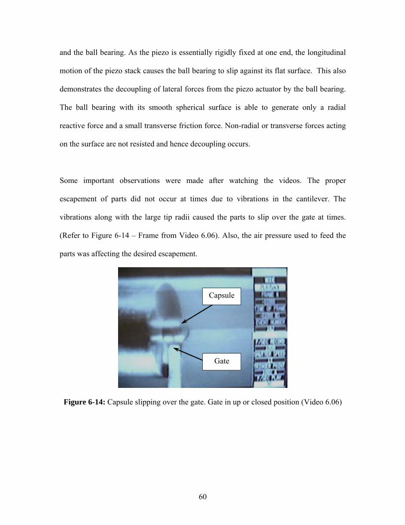
60
and the ball bearing. As the piezo is essentially rigidly fixed at one end, the longitudinal
motion of the piezo stack causes the ball bearing to slip against its flat surface. This also
demonstrates the decoupling of lateral forces from the piezo actuator by the ball bearing.
The ball bearing with its smooth spherical surface is able to generate only a radial
reactive force and a small transverse friction force. Non-radial or transverse forces acting
on the surface are not resisted and hence decoupling occurs.
Some important observations were made after watching the videos. The proper
escapement of parts did not occur at times due to vibrations in the cantilever. The
vibrations along with the large tip radii caused the parts to slip over the gate at times.
(Refer to Figure 6-14 – Frame from Video 6.06). Also, the air pressure used to feed the
parts was affecting the desired escapement.
Figure 6-14: Capsule slipping over the gate. Gate in up or closed position (Video 6.06)
Capsule
Gate
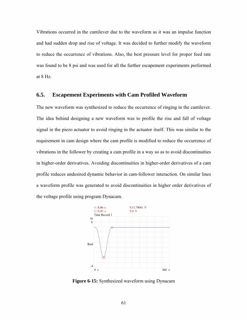
61
Vibrations occurred in the cantilever due to the waveform as it was an impulse function
and had sudden drop and rise of voltage. It was decided to further modify the waveform
to reduce the occurrence of vibrations. Also, the best pressure level for proper feed rate
was found to be 8 psi and was used for all the further escapement experiments performed
at 8 Hz.
6.5. Escapement Experiments with Cam Profiled Waveform The new waveform was synthesized to reduce the occurrence of ringing in the cantilever.
The idea behind designing a new waveform was to profile the rise and fall of voltage
signal in the piezo actuator to avoid ringing in the actuator itself. This was similar to the
requirement in cam design where the cam profile is modified to reduce the occurrence of
vibrations in the follower by creating a cam profile in a way so as to avoid discontinuities
in higher-order derivatives. Avoiding discontinuities in higher-order derivatives of a cam
profile reduces undesired dynamic behavior in cam-follower interaction. On similar lines
a waveform profile was generated to avoid discontinuities in higher order derivatives of
the voltage profile using program Dynacam.
Figure 6-15: Synthesized waveform using Dynacam
16V
-4
Real
s360 0 s
Time Record 1X:45 s Y:0 VX:86 s Y:11.79041 V
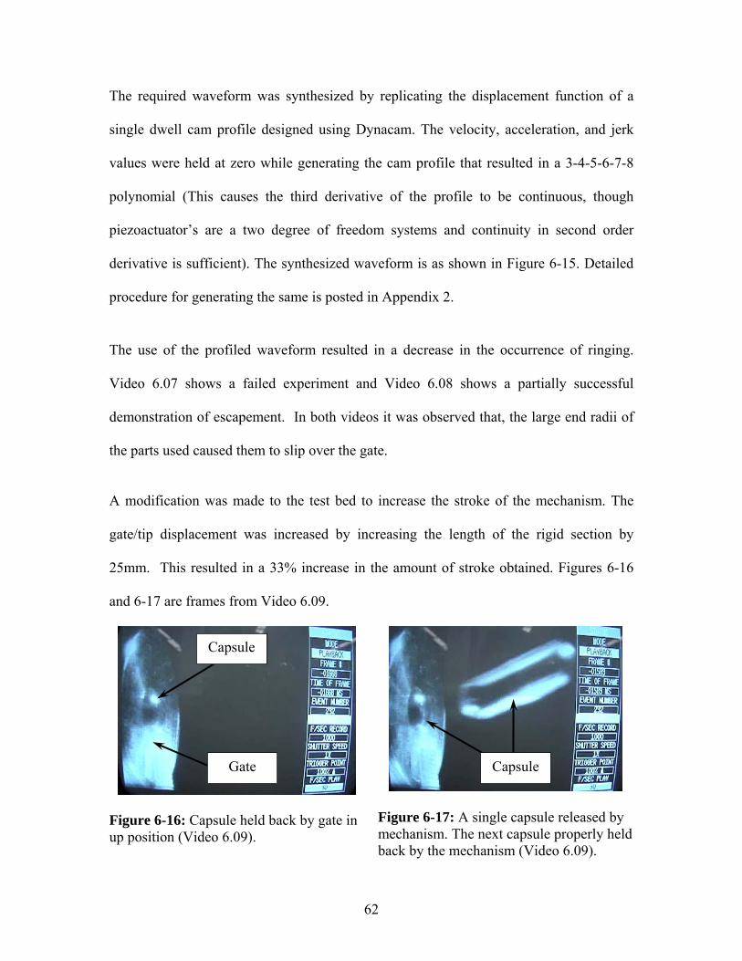
62
The required waveform was synthesized by replicating the displacement function of a
single dwell cam profile designed using Dynacam. The velocity, acceleration, and jerk
values were held at zero while generating the cam profile that resulted in a 3-4-5-6-7-8
polynomial (This causes the third derivative of the profile to be continuous, though
piezoactuator’s are a two degree of freedom systems and continuity in second order
derivative is sufficient). The synthesized waveform is as shown in Figure 6-15. Detailed
procedure for generating the same is posted in Appendix 2.
The use of the profiled waveform resulted in a decrease in the occurrence of ringing.
Video 6.07 shows a failed experiment and Video 6.08 shows a partially successful
demonstration of escapement. In both videos it was observed that, the large end radii of
the parts used caused them to slip over the gate.
A modification was made to the test bed to increase the stroke of the mechanism. The
gate/tip displacement was increased by increasing the length of the rigid section by
25mm. This resulted in a 33% increase in the amount of stroke obtained. Figures 6-16
and 6-17 are frames from Video 6.09.
Figure 6-16: Capsule held back by gate in up position (Video 6.09).
Figure 6-17: A single capsule released by mechanism. The next capsule properly held back by the mechanism (Video 6.09).
Capsule
Gate Capsule
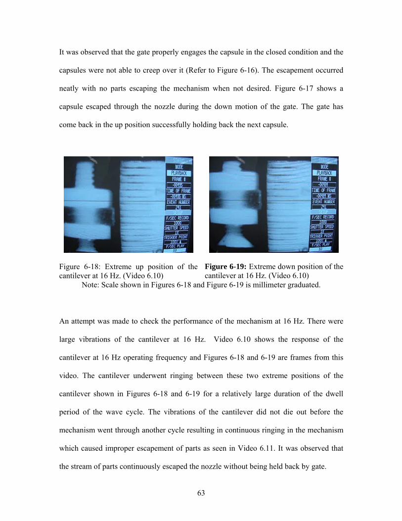
63
It was observed that the gate properly engages the capsule in the closed condition and the
capsules were not able to creep over it (Refer to Figure 6-16). The escapement occurred
neatly with no parts escaping the mechanism when not desired. Figure 6-17 shows a
capsule escaped through the nozzle during the down motion of the gate. The gate has
come back in the up position successfully holding back the next capsule.
Figure 6-18: Extreme up position of the cantilever at 16 Hz. (Video 6.10)
Figure 6-19: Extreme down position of the cantilever at 16 Hz. (Video 6.10)
Note: Scale shown in Figures 6-18 and Figure 6-19 is millimeter graduated.
An attempt was made to check the performance of the mechanism at 16 Hz. There were
large vibrations of the cantilever at 16 Hz. Video 6.10 shows the response of the
cantilever at 16 Hz operating frequency and Figures 6-18 and 6-19 are frames from this
video. The cantilever underwent ringing between these two extreme positions of the
cantilever shown in Figures 6-18 and 6-19 for a relatively large duration of the dwell
period of the wave cycle. The vibrations of the cantilever did not die out before the
mechanism went through another cycle resulting in continuous ringing in the mechanism
which caused improper escapement of parts as seen in Video 6.11. It was observed that
the stream of parts continuously escaped the nozzle without being held back by gate.

64
An attempt was made to improve the escapement of the mechanism by developing a
hold-back device. The aim of this device was to hold back the next consecutive capsule
as the earlier capsule was escaping the mechanism.
6.6. Escapement Experiments with Hold-Back Device A hole was provided on the rigid part of the cantilever to accommodate one end of a bent
wire in such a way that the other end could be inserted in the hole provided in the nozzle.
The pin would follow the motion of the cantilever and was required to hold back the
consecutive capsule while the capsule at the end of the nozzle was escaping the
mechanism. The holding back of capsules did not occur as desired and it was attributed to
low stiffness of the wire used to hold back the capsules.
Another attempt was made to make a stiffer hold-back device. A bent strip of aluminum
and a screw with lock nut arrangement at one end and the other end to be fixed over the
rigid section of the cantilever was made. Video 6.12 shows an attempt to run the
escapement experiment with the hold-back device. Figure 6-20 is a frame captured from
video 6.12 showing the capsule almost stuck at the gate. Video 6.13 shows the
hold-back mechanism stuck over the capsule. Figure 6-21 was captured from video 6.13
and shows the tip of the hold-back device stuck over capsule after landing on its surface.
As the mechanism was almost jammed, the stroke of mechanism was largely reduced
causing the capsule to move only slightly during each cycle. This causes the whole
mechanism to get jammed and the capsules slowly drag out of the nozzle.
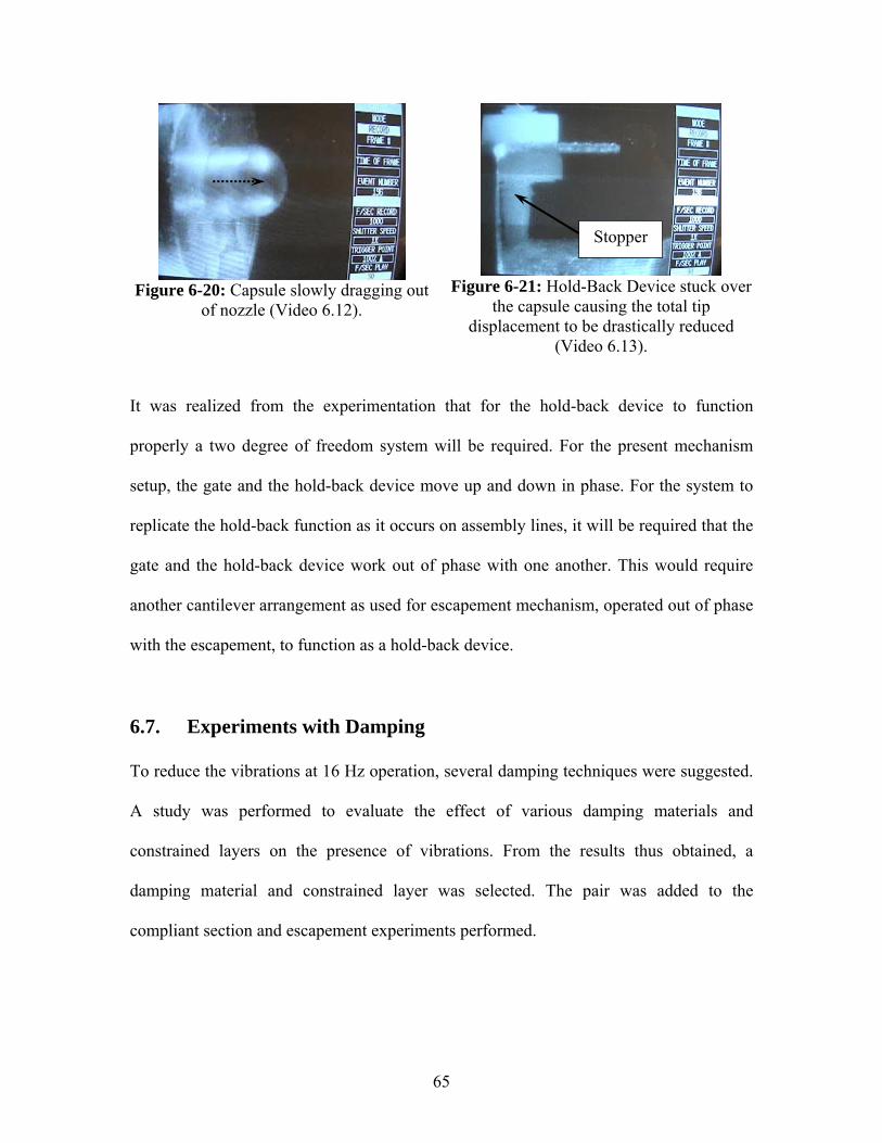
65
Figure 6-20: Capsule slowly dragging out
of nozzle (Video 6.12).
Figure 6-21: Hold-Back Device stuck over
the capsule causing the total tip displacement to be drastically reduced
(Video 6.13).
It was realized from the experimentation that for the hold-back device to function
properly a two degree of freedom system will be required. For the present mechanism
setup, the gate and the hold-back device move up and down in phase. For the system to
replicate the hold-back function as it occurs on assembly lines, it will be required that the
gate and the hold-back device work out of phase with one another. This would require
another cantilever arrangement as used for escapement mechanism, operated out of phase
with the escapement, to function as a hold-back device.
6.7. Experiments with Damping To reduce the vibrations at 16 Hz operation, several damping techniques were suggested.
A study was performed to evaluate the effect of various damping materials and
constrained layers on the presence of vibrations. From the results thus obtained, a
damping material and constrained layer was selected. The pair was added to the
compliant section and escapement experiments performed.
Stopper
66
6.7.1. Constrained Layer Damping Study The aim of the experimental study was to evaluate various damping materials and
constrained layers to reduce vibration. The study required applying various combinations
of damping materials and constrained layers to the compliant section of the cantilever.
The parameters altered were the material and thickness of both the damping and
constrained layers. The damping material evaluated were two different qualities of
double-sided foam tape and a specialty composite. The materials used for the constrained
layer were aluminum strip and paper. A pressure sensitive adhesive was used to bond the
layers.
The damping was evaluated by first treating the cantilever with a damping material and a
constrained layer. The cantilever was then excited using the internal source of the
Dynamic Signal Analyzer and its response obtained using an accelerometer fixed on the
cantilever. In the first study performed a Periodic Chirp signal was used to excite the
piezo actuator. The exciting signal was simultaneously fed to one of the channels of the
DSA. The response of the cantilever was captured using the accelerometer and was fed to
the other DSA channel. A uniform window was used to compute the vibration spectra of
the cantilever. The Frequency Response Function of the cantilever was found by dividing
the frequency spectra of the cantilever by the frequency spectra of the input signal, using
the DSA. Ten RMS averages were taken to increase the accuracy of results. Table 6-1
gives the results for this study. The time domain, frequency response, and coherence plots
for the test are shown in Appendix 3. In another study performed, an impulse signal
generated using the arbitrary function generator of the DSA was used to excite the piezo
actuator. The exciting signal is similar to hammer excitation and hence a force/expo

67
window was used. A force width of 30 ms and expo decay of 125 ms, with a negative
delay of -10 ms was the setting of DSA used. Table 6-2 gives the results for this study.
The time domain, frequency response, and coherence plots for the test are shown in
Appendix 4. Experiments were repeated twice with the same set of parameters. The
results were analyzed by plotting the data on a uniform scale and by comparing the Vrms
and damping coefficients for various combinations.

68
6.7.2. Escapement Experiment with Constrained Layer Damping The combination of foam tape 0.05" thick and aluminum strip 0.06" thick provides the
best damping of undesired vibrations in the cantilever. The cantilever was treated with
this pair of materials and escapement experiments performed at 16 Hz. Figures 6-22
through 6-24 were captured from Video 6.14. and show the proper functioning of the
mechanism.
Figure 6-22: Gate in up position causing the capsule to be held back (Video 6.14).
Figure 6-23: Gate moving down, allowing capsule to escape the nozzle (Video 6.14).
Figure 6-24: Gate in up position before next capsule tries to escape the nozzle
(Video 6.14).
Capsule
Gate
Capsule
Gate
Capsule

69
Table 6-1: Various combinations used to evaluate the damping introduced. Damping quantified for two peaks. Table sorted by area under the Frequency response between 40 Hz and 160 Hz
Data Set # Damping Material Constrained Layer Area
40 Hz - 160 Hz Area
220 Hz - 360 Hz 27 2 x 0.05" Foam Tape 0.06" Aluminum 7.327 55.45623 0.04" Foam Tape 0.06" Aluminum 9.511 70.16618 0.05" Foam Tape 0.06" Aluminum 9.582 70.91725 2 x 0.05" Foam Tape Paper 9.850 64.11017 0.05" Foam Tape No Constrained Layer 9.928 72.21120 0.04" Foam Tape Paper 10.025 79.395
10
2 x 0.06" EARSC (Glue Stick as Adhesive between compliant beam and first layer, 3M Super 77 spray between two EARSC layers)
0.06" Aluminum 10.092 67.805
15 0.05" Foam Tape Paper 10.105 69.33412 No Damping Material No Constrained Layer 10.254 80.646
8
2 x 0.06" EARSC (Glue Stick as Adhesive between compliant beam and first layer, 3M Super 77 spray between two EARSC layers)
No Constrained Layer 10.364 73.733
24 No Damping Material No Constrained Layer 10.584 79.5755 0.06" EARSC (Glue Stick as Adhesive) No Constrained Layer 11.155 30.6992 0.06" EARSC (Glue Stick as Adhesive) No Constrained Layer 11.491 55.144
11
2 x 0.06" EARSC (Glue Stick as Adhesive between compliant beam and first layer, 3M Super 77 spray between two EARSC layers)
0.06" Aluminum 11.703 *57.289
* No peak
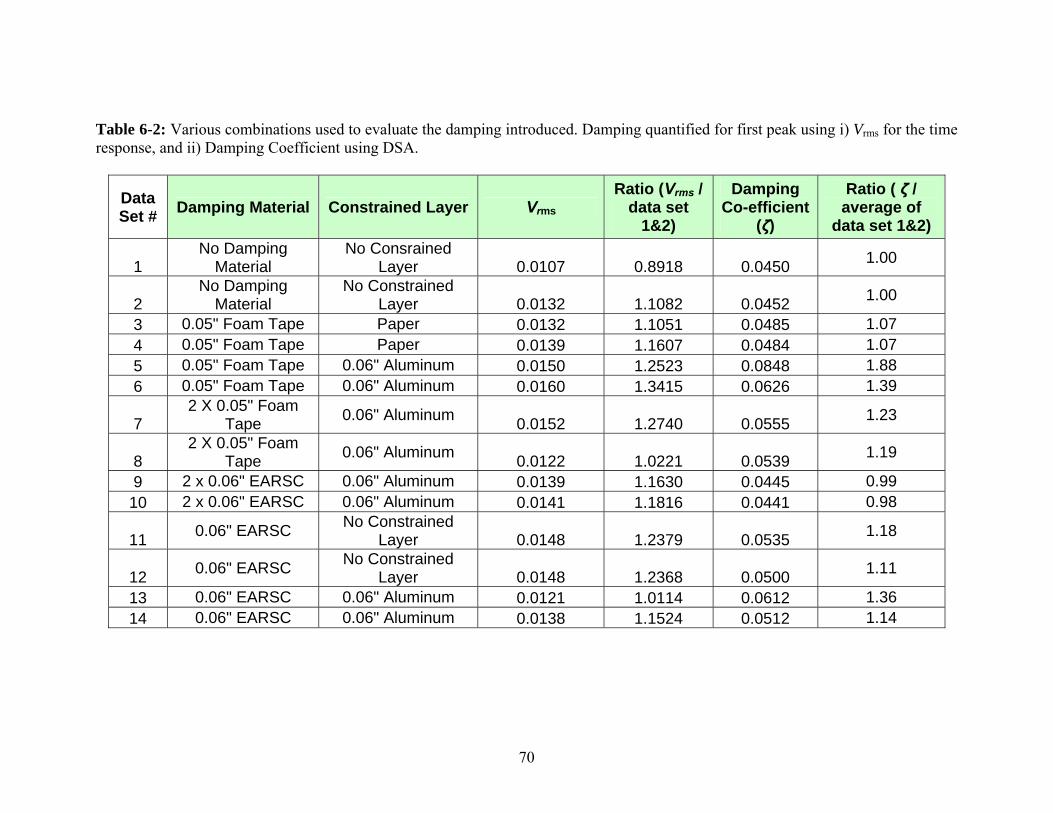
70
Table 6-2: Various combinations used to evaluate the damping introduced. Damping quantified for first peak using i) Vrms for the time response, and ii) Damping Coefficient using DSA.
Data Set # Damping Material Constrained Layer Vrms
Ratio (Vrms / data set
1&2)
Damping Co-efficient
(ζ)
Ratio ( ζ / average of
data set 1&2)
1 No Damping
Material No Consrained
Layer 0.0107 0.8918 0.0450 1.00
2 No Damping
Material No Constrained
Layer 0.0132 1.1082 0.0452 1.00
3 0.05" Foam Tape Paper 0.0132 1.1051 0.0485 1.07 4 0.05" Foam Tape Paper 0.0139 1.1607 0.0484 1.07 5 0.05" Foam Tape 0.06" Aluminum 0.0150 1.2523 0.0848 1.88 6 0.05" Foam Tape 0.06" Aluminum 0.0160 1.3415 0.0626 1.39
7 2 X 0.05" Foam
Tape 0.06" Aluminum 0.0152 1.2740 0.0555 1.23
8 2 X 0.05" Foam
Tape 0.06" Aluminum 0.0122 1.0221 0.0539 1.19
9 2 x 0.06" EARSC 0.06" Aluminum 0.0139 1.1630 0.0445 0.99 10 2 x 0.06" EARSC 0.06" Aluminum 0.0141 1.1816 0.0441 0.98
11 0.06" EARSC No Constrained Layer 0.0148 1.2379 0.0535 1.18
12 0.06" EARSC No Constrained Layer 0.0148 1.2368 0.0500 1.11
13 0.06" EARSC 0.06" Aluminum 0.0121 1.0114 0.0612 1.36 14 0.06" EARSC 0.06" Aluminum 0.0138 1.1524 0.0512 1.14
71
7. RESULTS
The feasibility of using a novel approach to high speed escapement of parts using a piezo
actuator and a compliant mechanism was demonstrated. A proof-of-principle prototype
was designed, fabricated, and tested. The device performed according to the set
requirements at 16 Hz operating frequency. The mechanism has a displacement gain of
35 giving an output displacement of 1.2 mm with an input displacement of 35 μm.
Improvement in performance from 8 Hz to 16 Hz operating frequency was achieved
using constrained layer damping techniques.
The final design of this escapement design consists of a cantilever beam comprised of a
compliant section made of spring steel and a relatively rigid extension section made of
lexan. The compliant section was fitted with a 0.05” thick foam tape as a damping layer
and 0.06” thick aluminum sheet as a constrained layer to improve the dynamic
performance of the mechanism. A piezoelectric actuator was made to push against a ball
bearing resting inside a block of material. The block was bolted to one end of the rigid
section of the cantilever beam. A gate was provided at other end of the rigid section that
alternatively blocked and allowed the capsules to escape through the nozzle. A nozzle
was used to keep proper orientation of capsules with respect to the gate. The capsules
were driven to the tip by filling them up in a PVDF tubing and blowing them through it
using shop air at 8 psi.
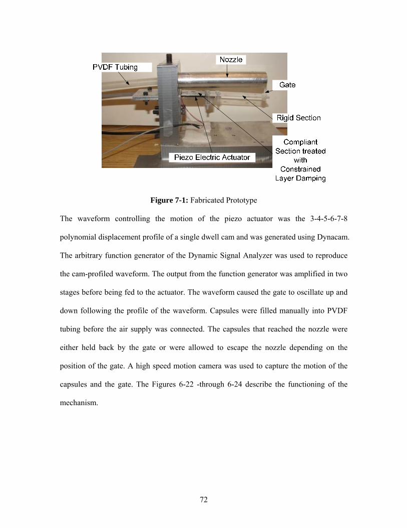
72
Figure 7-1: Fabricated Prototype
The waveform controlling the motion of the piezo actuator was the 3-4-5-6-7-8
polynomial displacement profile of a single dwell cam and was generated using Dynacam.
The arbitrary function generator of the Dynamic Signal Analyzer was used to reproduce
the cam-profiled waveform. The output from the function generator was amplified in two
stages before being fed to the actuator. The waveform caused the gate to oscillate up and
down following the profile of the waveform. Capsules were filled manually into PVDF
tubing before the air supply was connected. The capsules that reached the nozzle were
either held back by the gate or were allowed to escape the nozzle depending on the
position of the gate. A high speed motion camera was used to capture the motion of the
capsules and the gate. The Figures 6-22 -through 6-24 describe the functioning of the
mechanism.
73
8. CONCLUSIONS
The new mechanism has several advantages over the existing one. The design is simple
and occupies significantly less design space. Better control over the dynamic behavior of
the mechanism is possible by using wave shaping techniques and control algorithms. The
mechanism is adaptable to any existing system and is an alternative for parts escapement
on new assembly machines.
The mechanism is a combination of a motion amplifying device with a relatively high
frequency response. In addition to parts escapement, the concept as developed can be
used in gating operations up to 16 Hz and up to a tip displacement of 1.2 mm.
Improvement in performance can be achieved by optimizing the design parameters and
using precise manufacturing techniques.
Large presence of vibrations in the cantilever during 16 Hz and higher operating
frequencies also caused undesired escapement of the parts. These vibrations can be
controlled by selecting proper values for the critical parameters of the cantilever. Also,
different waveform contours and control algorithms can be experimented with to control
vibrations. Active vibration controls on the cantilever can also be studied.
The performance of the mechanism can be improved by developing a functional
hold-back device. The hold-back device developed during the research activity was not
successful because it was operating in phase with the gating device. A two degree of
freedom mechanism with the hold-back device operating out of phase with the gating

74
device will be able to replicate the cam driven escapement mechanism currently being
used on the assembly line. A piezoelectric driven mechanism similar in construction to
the gating mechanism and being made to operate out of phase using proper control
techniques will improve the functionality of the mechanism.

75
9. RECOMMENDATIONS
The performance level and applicability of the technique can be improved. To maximize
the benefits, the following recommendations are made.
a Optimize the Mechanism: A mechanism can be redesigned for better dynamic
performance. The material and the cross section of the cantilever can be changed to
achieve this. The position of the actuator and the length of the cantilever section can
be changed to achieve better results.
b Develop a Coupled Device: Two similar mechanisms can be developed to operate
out of phase to correctly replicate the functioning of a cam-follower-based
mechanism. An attempt was made to develop a hold-back device. It was realized that
for the hold-back function to occur properly, the degree of freedom of the mechanism
will have to be increased and that can be achieved by two similar mechanisms
operating out of phase.
c Investigate the use of closed loop control: A study can be performed in which a
closed loop control can be developed to nullify the effect of ambient vibrations of the
of piezo mechanism. The control would involve measuring the ambient vibrations
around the mechanism and modifying the input to the actuator in a way so as to
reduce the undesired effects.

76
d The large radii of the parts used for escapement caused them to slip over the gate at
many instances. To avoid this problem on assembly lines, features of the parts having
sharp edges can be made to interact with the gate to result in proper escapement.

77
REFERENCES
1. Metin Sitti, Domenico Campolo, Joseph Yan, Ronald S. Fearing , "Development of PZT and PZN-PT Based Unimorph Actuators for Micromechanical Flapping Mechanisms", Proceedings of the 2001 IEEE International Conference on Robotics 8 Automation Seoul, Korea. May 21-26, 2001
2. F. Claeyssen, R. Le Letty, F. Barillot, N. Lhermet, H. Fabbro, P. Guay, M. Yorck, P. Bouchilloux , "Mechanisms Based on Piezo Actuators", Department of Mechanical Engineering. The University of Michigan, Ann Arbor, MI 48109
3. David J. Cappelleri, Mary I. Frecker, Timothy W. Simpson, "Design of a PZT Bimorph Actuator Using a Metamodel-Based Approach".
4. G. K. Ananthasuresh ,Larry L. Howell "Mechanical Design of Compliant Microsystems—A Perspective and Prospects", Journal of Mechanical Design.
5. S. Kota, K.-J. Lu, Z. Kreiner, B. Trease, J. Arenas, J. Geiger , "Design and Application of Compliant Mechanisms for Surgical Tools", Journal of Biomechanical Engineering.
6. Kerr-Jia Lu, Sridhar Kota , "Design of Compliant Mechanisms for Morphing Structural Shapes", Department of Mechanical Engineering, University of Michigan, Ann Arbor.
7. V. K. Varma and W. E. Dixon , "Design of a Piezoelectric Meso-scale Mobile Robot: A Compliant Amplification Approach", Oak Ridge National Laboratory, Oak Ridge.
8. Smita Bharti, Mary I. Frecker , "Optimal Design and Experimental Characterization of a Compliant Mechanism Piezoelectric Actuator for Inertially Stabilized Rifle", Department of Mechanical and Nuclear Engineering, Pennsylvania State University.
9. Smita Bharti, Mary Frecker , "Compliant Mechanical Amplifier Design Using Multiple Optimally Placed Actuators", Engineering Congress and Exposition Washington, D.C., November 15-21, 2006.
10. S. Canfield and M. Frecker , "Topology optimization of compliant mechanical amplifiers for piezoelectric actuators ", Struct Multidisc Optim 20, 269–279.
11. Mostafa Abdalla, Mary Frecker, ZaferGurdal, Terrence Johnson and Douglas K Lindner , "Design of a piezoelectric actuator and compliant mechanism combination for maximum energy efficiency", Institute of Physics Publishing Smart Materials and Structures, 14(2005) 1421–1430.
78
12. J. Li , R. Sedaghati,and J. Dargahi , "Design and Development of Piezoelectric Inchworm Actuator", 45th AIAA/ASME/ASCE/AHS/ASC Structures, Structural Dynamics & Materials Conference 19 - 22 April 2004.
13. S. Venanzi, P. Giesen, V. Parenti-Castelli,"A novel technique for position analysis of planar compliant mechanisms",Mechanism and Machine Theory 40 (2005) 1224-1239.
14. Jinyong Joo, Sridhar Kota , Noboru Kikuchi , "Large Deformation Behavior of Compliant Mechanisms", Proceedings of 2001 ASME Design Engineering Technical Conferences Pittsburgh, Pennsylvania, USA.
15. Charles J. Kim, Sridhar Kota, Yong-Mo Moon , "An Instant Center Approach to the Conceptual Design of Compliant Mechanisms ", Proceedings of DETC-2004: 2004 International Design Engineering Technical Conference September 28-October 2, 2004 Salt Lake City, Utah.
16. Zhe Li, Sridhar Kota , " Dynamic Analysis of Compliant Mechanisms", ASME 2002.
17. Xinlin P. Qinga, , Hian-Leng Chana, Shawn J. Bearda, Teng K. Ooib, Stephen A. Marotta , "Effect of adhesive on the performance of piezoelectric elements used to monitor structural health", International Journal of Adhesion & Adhesives 26 (2006) 622–628.

79
BIBLIOGRAPHY AND REFERENCES
Howell, L. L., “Compliant Mechanisms”, John Wiley & Sons Canada, Ltd.; 1 edition (Jul 20 2001). Neklutin, C. N., “Mechanisms and cams for automatic machines; influence of dynamic forces on high-speed machine components.” American Elsevier Publishing Company, Inc. New York, 1969. Norton, R. L., “Machine Design, An Integrated Approach”, Prentice Hall, New Jersey, 1996 Norton, R. L., “ Design of Machinery, An Introduction to Synthesis and Analysis of Mechanisms and Machines” Mc Graw-Hill, Inc., New York, 2004 Rao, S., “Mechanical Vibrations”, 3rd Edition, Addison-Wesley Publishing Company, Reading, Massachusetts, 1990. Meirovitch, L. “Elements of Vibration Analysis, 2nd Edition”, McGraw-Hill, Inc., NewYork, 1986.
Yoshikazu Hishinuma, Eui-Hyeok Yang ,Jian-Gong Cheng, Susan Trolier-McKinstry "Optimized Design, Fabrication and Characterization of PZT Unimorph Microactuators for Deformable Mirrors", Proceedings of 2004 ASME International Mechanical Engineering Congress and RD&D Expo November 13-1 9,2004, Anaheim, California Nicholas J. Oosting ,Julie Hennessy, David T. Hanner, Dave Fang "Application of a Constrained Layer Damping Treatment to a Cast Aluminum V6 Engine Front Cover", 2004 SAE International W. Wilkie, J. High, J. Bockman , "Reliability Testing of NASA Piezocomposite Actuators" K Y Lamand T Y Ng , "Active control of composite plates with integrated piezoelectric sensors and actuators under various dynamic loading conditions", Institute of High Performance Computing, National University of Singapore C.K. Lee , "Theory of laminated piezoelectric plates for the design of distributed sensors/actuators. Part I: Governing equations and reciprocal relationships", IBM Research Division A, lmaden Research Center www.physikinstrumente.com www.piezo.com www.earsc.com

80
APPENDIX 1
Procedure to synthesize waveform using HP 3314A

81
Procedure to synthesize waveform using HP 3314 A:
Set up the instruments as shown in the Figure 1. The output of the function generator is
fed to DSA to observe the shape of waveform being generated.
Figure 1: Setup for synthesizing a waveform using HP 3314 A.
1. Turn ON the function generator.
2. Press the ARB key.
3. Select a Number key 0-5 to select the waveform register.
4. Press the amplitude key.
5. Turn the dial knob to set voltage to 1.15 V.
6. Press insert vector key. (This makes total vectors available to 3).
7. Press Vector Marker Key.
8. Turn the dial knob to set the Marker to #1.
9. Press vector height key.
10. Turn the dial knob to reach value of 1640.
11. Press vector length key.
12. Turn the dial knob to set the length to 10 units.
13. Press the frequency knob.
14. Turn the dial knob to reach the required frequency of 10 Hz.

82
Figure below shows synthesized waveform -
16V
-4
Real
ms499.51170 s
Time 1X:19.53125 ms Y:-254.9579 mVX:37.10938 ms Y:11.81937 V
Figure 1: Synthesized Waveform.
Note: To make a more complex waveform, insert the desired number of vectors
by repeating Step 6. Follow steps 8 – 12 to modify each of the vectors.

83
APPENDIX 2
Procedure to generate the shaped waveform using
Dynacam and HP 35665 Dynamic Signal Analyzer.

84
1. Using the professional version of Dynacam generate a Cam profile for 2 segment
polynomial function with 90° rise- fall segment and 270° dwell.
Notes:
a. Choose the value for Delta Theta (Deg): between 1 and 0.25. Selecting 0.125 will
cause the number of data points available to be greater than the maximum limit in the
arbitrary function generator of the HP35665A analyzer.
b. Set the Boundary conditions for the 1st segment. The settings are all initial and final
displacements, velocities, accelerations and jerks are zero. The displacement of the
follower at 45° is set to 10mm.
2. After entering the SVAJ data size the cam.
3. Export the spread sheet of CAM data, which is saved as a .txt file.
4. Open the .txt file using MS Excel. Copy the column containing the displacement data
save it in .csv format.
5. Open the .csv file using HP 35639A Data Viewer. The graph being viewed is the
shape of the waveform generated.
6. Save the file as a SDF file which has .dat extension.
7. The file can now be loaded in the Data Register of HP35665 Dynamic Signal
Analyzer and then can be used to generate the required waveform. Figure () shows the
resulting waveform.

85
8. To use the waveform as an input to the mechanism (piezo actuator), go to source
option on the DSA. Press arbitrary source setup and select the data register used to store
the waveform.
9. The frequency of the waveform is changed by changing the frequency span of the
analyzer.
10. The level of the signal can be adjusted to a maximum of 5V. The piezo actuator
selected requires 110 V input for full displacement, which means the input to the
amplifier should be 11V. (The piezo amplifier has a constant gain of 10). A voltage
signal amplifier was used to step up the input to the required level.
16V
-4
Real
s360 0 s
Time Record 1X:45 s Y:0 VX:86 s Y:11.79041 V

86
APPENDIX 3
CAD Drawings

87
ASSEMBLY DRAWING
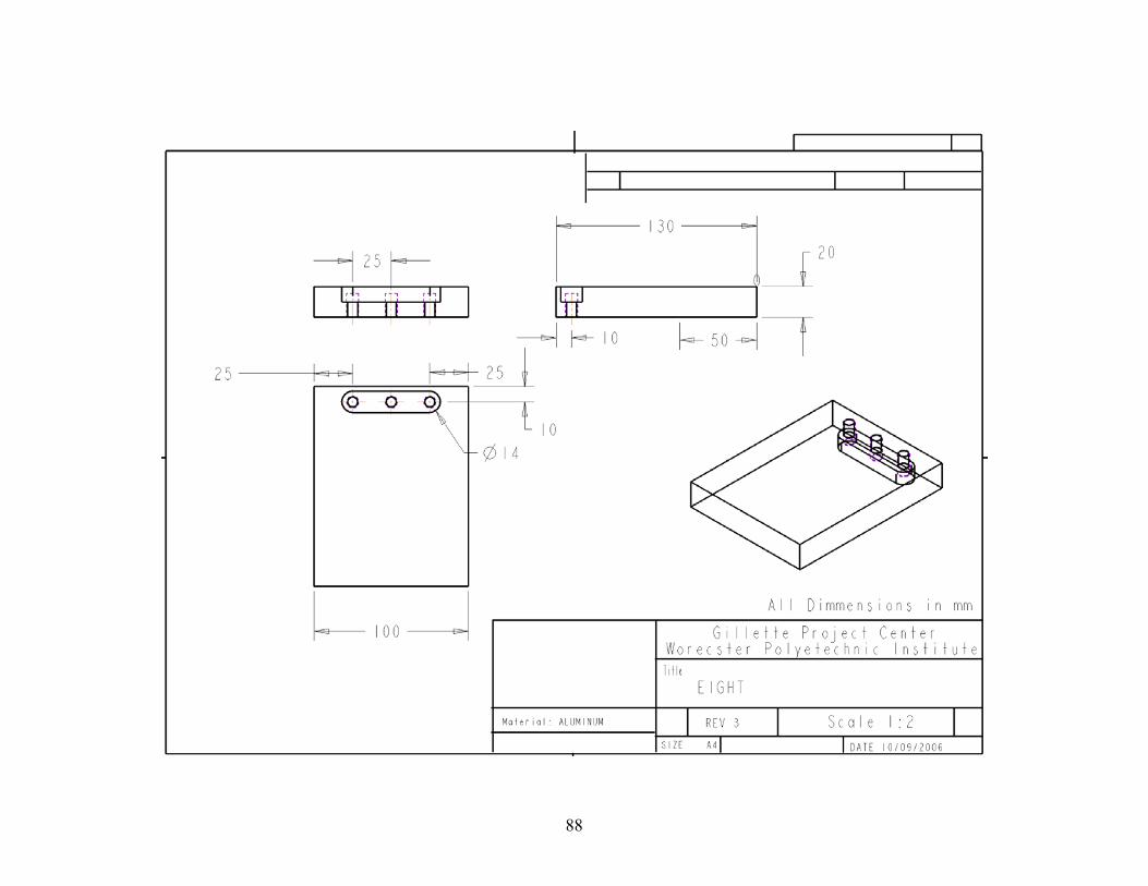
88

89

90
Lexan
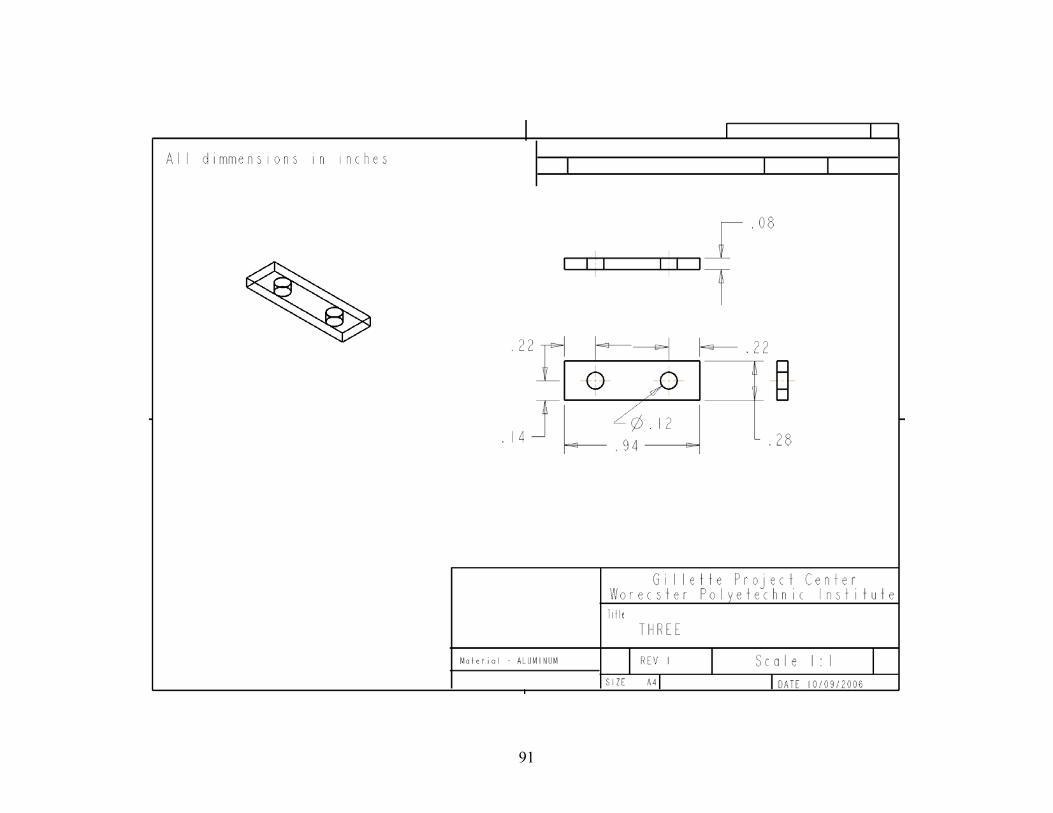
91
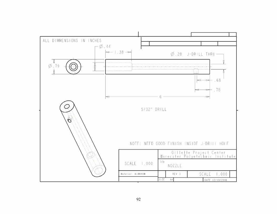
92
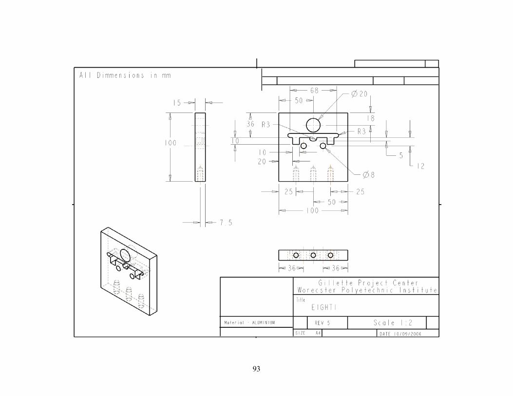
93

94
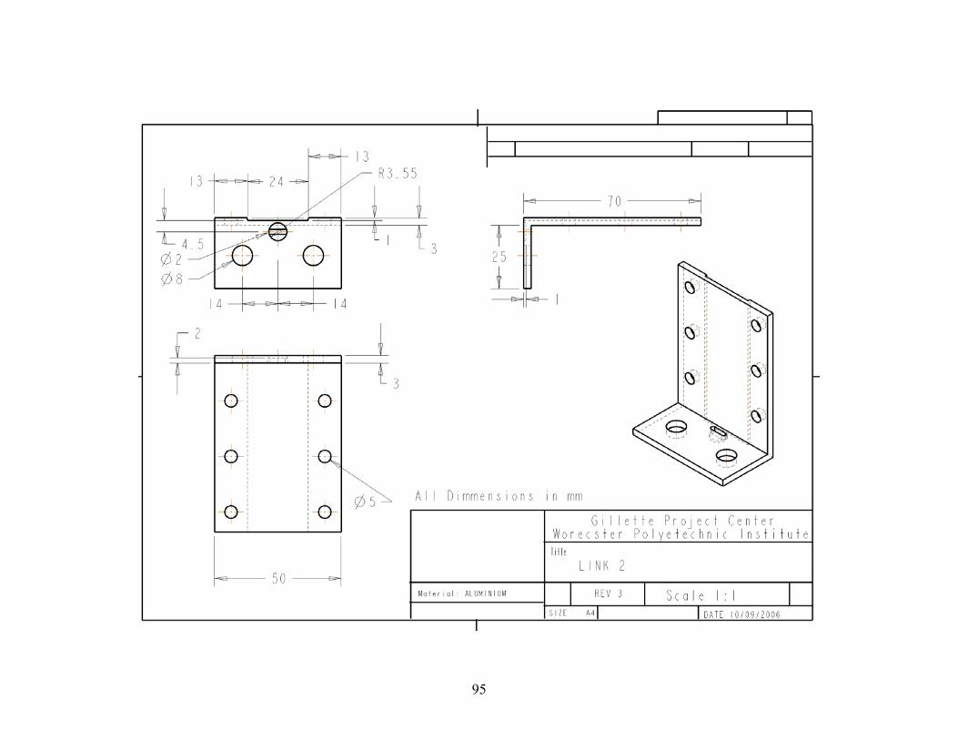
95

96
APPENDIX 4
Damping Experiment #1 Data

97

98
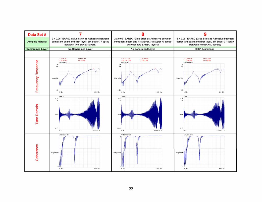
99

100

101

102
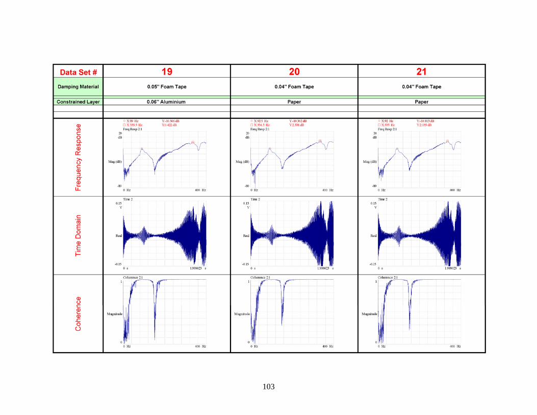
103

104

105
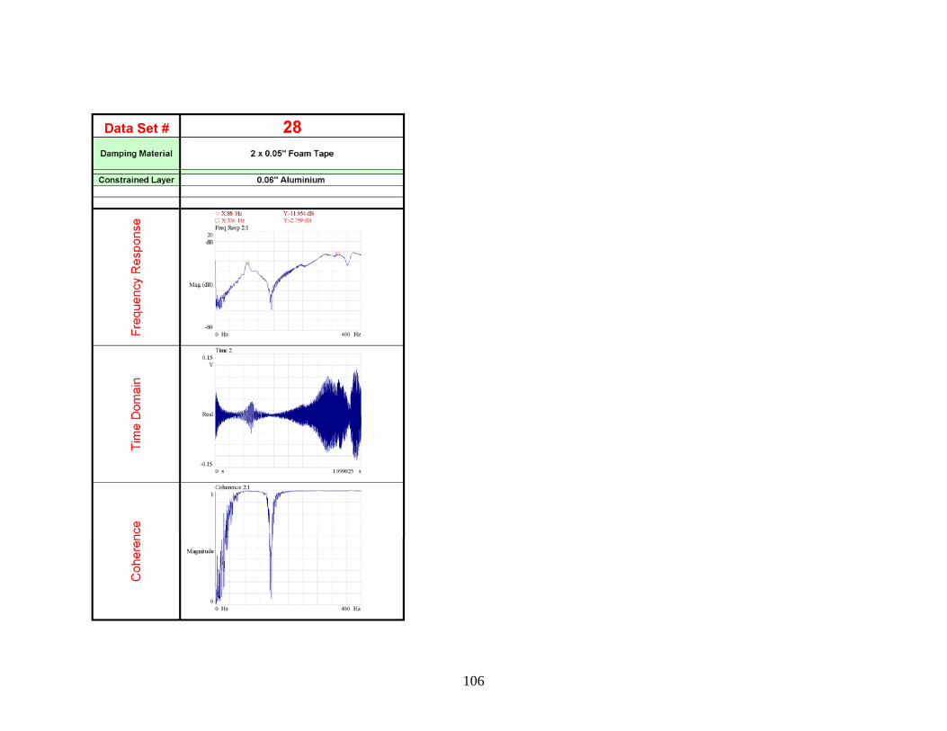
106

107
APPENDIX 5
Damping Experiment #2 Data

108

109

110

111

112
APPENDIX 6
Purchased Components
TESTBED COMMERCIAL PARTS LIST
ITEM COMPANY DESCRIPTION QUANTITY
1Physik Instrumente
P885.90 Low Voltage Piezo Stack Actuator 1
2Physik Instrumente
P663 Low Voltage Piezo Amplifier 1
3Physik Instrumente
P-890.10 LVPZT Cable LEMO/Blunt End 1
4 5
HARDWARE AND FASTENERS
ITEM COMPANY DESCRIPTION QUANTITY
7 Hillman 6-32 X 1/2" Nylon Screws Binding Head 5
8 Hillman 6-32 X 1" Nylon Screws Binding Head 2
9 Hillman 6-32 Nylon Nuts 10 10 Pneumatic Tool Adapter 2
11 5-16/18 Allen Headed Screws 4
12 Loctite 414 -Cyanoacrylate adhesive
13 14 15