Embed Size (px)
Citation preview

ISSN 1453 – 7303 “HIDRAULICA” (No. 1/2014) Magazine of Hydraulics, Pneumatics, Tribology, Ecology, Sensorics, Mechatronics
NUMERICAL MODELING OF VISCOUS FLUID FLOW BY SEALING LABYRINTHS
Lecturer PhD. Eng. Sanda BUDEA1, Eng. Ştefan SIMIONESCU2 1 University Politehnica Bucharest, Faculty of Power Engineering, [email protected] 2 INOE 2000 - IHP, [email protected]
Abstract: This paper analyzes laminar viscous fluid flow through interstices in order to properly design the labyrinth seals and improve the volumetric efficiency of the turbomachines. The theoretical study and hydrodynamic modeling of the threedimensional flow inside the labyrinth was made using a CFD application - ANSYS® Fluent, on different labyrinth geometries. There were determined: the flow spectrum, axial, tangential and total velocities, pressure variations along the labyrinths. From the analysis of three different geometries of labyrinth with baffles, resulted an optimal geometry for the sealing labyrinths of turbomachines, in terms of the gaps between the fixed and the rotating ring and the depth of the baffles. The numerical results also allowed the evaluation of the pressure losses along the maze, leading to the conclusion that the best geometry for labyrinths with baffles is the one were the width of the flow channel is equal or less than the baffle depth. Keywords: sealing labyrinth, baffle, turbomachine, geometry. 1. Introduction This paper analyzes the laminar flow of viscous fluids through interstices in order to properly design the labyrinth seals between the rotor and the housing and improve the volumetric efficiency of turbomachines. In order to increase the volumetric efficiency of centrifugal turbomachines, especially at relatively small flow rates and high pressures, losses of fluid through the interstices with or without baffles of the non-contact seal between the rotor’s suction diameter and the housing have to be minimized. At the turbomachine rotors, fluid flow velocities through labyrinths are relatively large and heat is released.
Fig.1 Labyrinths used for hydraulic turbomachine rotors [5]
I – straight labyrinths without or with baffles; II – labyrinths with threshold; III – storeyed labyrinths for high pressure rotors; IV – labyrinths for hydraulic turbomachines with two pieces housing
Due to the small size of the interstice, from tenths of millimeter in the case of high-pressure pumps, to milimeters for the hydraulic turbines and large fans, the flow of the real fluid is in many cases
32

ISSN 1453 – 7303 “HIDRAULICA” (No. 1/2014) Magazine of Hydraulics, Pneumatics, Tribology, Ecology, Sensorics, Mechatronics
laminar, occuring at low Reynolds numbers, which does not eliminate the mathematical complexity of solving spatial viscous fluid flow through these interstices. The great constructive variety of labyrinths led us to a classification shown in Figure 1, the theoretical research in this article is exemplified for the straight labyrinth with baffles. 2. Numerical solving of the viscous fluid flow through the interstice of baffled labyrinths
The research in terms of hydrodynamic fluid flow through the labyrinths presents interest, both in pumping liquids with different viscosities, as well as for the calculation of the volumetric efficiency of the turbomachines. Given the complexity of the spatial flow, with axial symmetry of the viscous fluid through the sealing labyrinths equipped with baffles, solving the nonlinear system of equations of Navier - Stokes is possible only by numerical integration. The Computational Fluid Dynamics program ANSYS® Fluent 14 was used to analyse the threedimensional fluid flow inside the labyrinth seal of a turbomachine. Specific geometry elements of the labyrinth in triortogonal system and flow parameters on the labyrinth’s inlet and outlet are shown in Figure 2, in which we noted R – rotor, C – casing, ω - angular velocity, δ - size of the labyrinth gap, pi – labyrinth inlet pressure, pe – labyrinth outlet pressure, Ri – labyrinth radius.
Fig. 2 Scheme of flow through the labyrinth in the
meridian plane of a turbomachine [5] 2.1. Simplifying assumptions and boundary conditions In the mathematical modeling of the three-dimensional viscous fluid flow through the labyrints of a turbomachine, the following simplifying assumptions have been used: permanent movement (𝜕 𝜕𝑡⁄ = 0), incompressible viscous liquid, movement with axial symmetry around Y axis and the interstice radius 𝑅𝑖 ≫ 𝛿. Solving the three-dimensional movement of liquid through the labyrinth of the hydraulic turbomachine consists in finding the axial and tangential flow velocities, to verify the boundary conditions:
- on the surface of the sealing ring on the rotor, the condition of adhesion of the liquid, 𝑉𝑅 = 𝑈��⃗ = 𝑅�⃗ × 𝜔 ≈ 𝑐𝑜𝑛𝑠𝑡. (1)
- on the surface of the sealing ring on the casing, for the same reason the speed on the casing is 𝑉𝐶 = 0 (2)
- at the inlet and outlet from the labyrinth interstitium, the peripheral component is assumed to have a linear distribution: 𝑈 = 𝑈(0, 𝑧) = 𝑈(𝑙, 𝑧) = 𝑈𝑅 ∙ 𝑧 (3)
33
ISSN 1453 – 7303 “HIDRAULICA” (No. 1/2014) Magazine of Hydraulics, Pneumatics, Tribology, Ecology, Sensorics, Mechatronics
There were analyzed several geometries of labyrinths with baffles, of which 3 were the most conclusive and are presented in the following:
1. Labyrinth depth 0.25 mm and channel width 0.75 mm; 2. The 2 sizes equal to 0.5 mm, respectively; 3. Labyrinth depth 0.75 mm and channel width 0.25 mm.
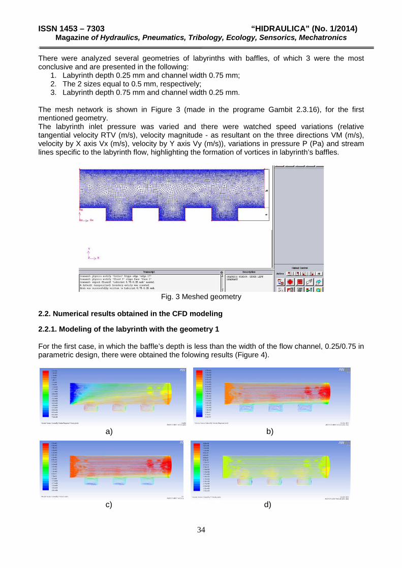
The mesh network is shown in Figure 3 (made in the programe Gambit 2.3.16), for the first mentioned geometry. The labyrinth inlet pressure was varied and there were watched speed variations (relative tangential velocity RTV (m/s), velocity magnitude - as resultant on the three directions VM (m/s), velocity by X axis Vx (m/s), velocity by Y axis Vy (m/s)), variations in pressure P (Pa) and stream lines specific to the labyrinth flow, highlighting the formation of vortices in labyrinth’s baffles.
Fig. 3 Meshed geometry
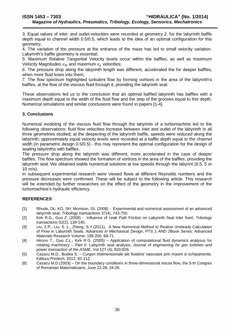
2.2. Numerical results obtained in the CFD modeling 2.2.1. Modeling of the labyrinth with the geometry 1 For the first case, in which the baffle’s depth is less than the width of the flow channel, 0.25/0.75 in parametric design, there were obtained the folowing results (Figure 4).
a) b)
c) d)
34

ISSN 1453 – 7303 “HIDRAULICA” (No. 1/2014) Magazine of Hydraulics, Pneumatics, Tribology, Ecology, Sensorics, Mechatronics
e) f) Fig. 4 a) Relative tangential velocity 𝑅𝑇𝑉, b) velocity magnitude 𝑣𝑀, c) velocity by 𝑥, 𝑣𝑥, d) velocity
by 𝑦, 𝑣𝑦, e) pressure distribution and f) stream lines spectrum From the results obtained it was observed an increase in speed between the inlet and outlet of the labyrinth, so the relative tangential velocity increased from -0.5 m/s at the entrance to 0.6 m/s at the outlet, the velocity magnitude - the resultant velocity representing the 2 directions - increased from 7 m/s at the entrance to 8.7 m/s at the outlet, the speed 𝑣𝑥 on the horizontal direction has increased from 6.8 m/s to 8.7 m/s, and 𝑣𝑦 on the vertical direction from -0.1 m/s at input to 0.6 m/s at the outlet of the labyrinth. Within the baffles, 𝑣𝑀 and 𝑣𝑥 velocities are lower, you can see the vortices formed in the liquid flow and the pressure drop ∆𝑝 along the labyrinth is observed to decrease is from about 100000 𝑃𝑎 to 5500 𝑃𝑎, variation illustrated in Figure 7. The increase in speed is also checked by the pressure drop along the labyrinth. The vortices formed within the baffles ensure proper sealing of the flow, thus leading to the reduction of leakage flow and a better volumetric efficiency.
2.2.2. Modeling of the labyrinth with the geometry 2 The case when the baffle’s depth is equal to the width of the flow channel, 0.5 / 0.5 in parametric design, has led to the the folowing results (Figure 5):
a) b)
b) d)
35

ISSN 1453 – 7303 “HIDRAULICA” (No. 1/2014) Magazine of Hydraulics, Pneumatics, Tribology, Ecology, Sensorics, Mechatronics
e) f) Fig. 5 a) Relative tangential velocity 𝑅𝑇𝑉, b) velocity magnitude 𝑣𝑀, c) velocity by 𝑥, 𝑣𝑥, d) velocity
by 𝑦, 𝑣𝑦, e) pressure distribution and f) stream lines spectrum An analysis of the results obtained showed an increase in speed between the inlet and outlet of the labyrinth, so the relative tangential velocity increased from -3.5 m/s at the entrance to -0.7 m/s at the outlet; the velocity magnitude 𝑣𝑀 increased from 3.88 m/s at the inlet to 4.8 m/s at the outlet; the velocity on horizontal direction 𝑣𝑥 has increased from 3.95 m/s to 4.83 m/s, and the vertical velocity component 𝑣𝑦 from -0.2 m/s at the entrance to 0.2 m/s at the labyrinth’s outlet. Within the baffles, the velocities 𝑣𝑀 and 𝑣𝑥 are much lower, the vortices formed in the liquid flow can be clearly seen, and the pressure drop ∆𝑝 along the labyrinth decreases from about 109000 𝑃𝑎 to 4800 𝑃𝑎 (see also figure 7). From the stream lines spectrum can be observed the formation of vortices in the labyrinth’s baffles, a "dead zone", who ensures the seal between rotor and housing of the turbomachine.
2.2.3 Modeling of the labyrinth with the geometry 3 Geometry 3 refers to the baffle’s depth greater than the width of the flow channel in relation 0.75 / 0.25 in parametric design. In this case were obtained the folowing results (Figure 6):
a) b)
b) d)
36

ISSN 1453 – 7303 “HIDRAULICA” (No. 1/2014) Magazine of Hydraulics, Pneumatics, Tribology, Ecology, Sensorics, Mechatronics
e) f)
Fig. 6 a) Relative tangential velocity 𝑅𝑇𝑉, b) velocity magnitude 𝑣𝑀, c) velocity by 𝑥, 𝑣𝑥, d) velocity by 𝑦, 𝑣𝑦, e) pressure distribution and f) stream lines spectrum
Analyzing the results of numerical integration, an increase in speed between the inlet and outlet of the labyrinth can be noticed, so the relative tangential velocity increased from -1 m/s at the entrance to 0.15 m/s on exit; the velocity magnitude 𝑣𝑀 increased from 1.2 m/s at the input to 1.6 m/s at the outlet; the speed on the 𝑥 direction 𝑣𝑥 has increased from 1.2 m/s to 1.3 m/s, and the component 𝑦, 𝑣𝑦 from -0.15 m/s to 0.03 m/s of these smaller labirint. This velocity lead us to conclude that a greater depth of the baffle of the labyrinth is not convenient in terms of hydrodynamics. The pressure drop along the labyrinth was accelerated. The observed decrease of ∆𝑝 is from about 150,000 𝑃𝑎 to 16,000 𝑃𝑎, as shown in Figure 7. The pressure drop along the length of the labyrinth, for the three geometries, was represented in the graph in Figure 7. As can be seen from the numerical simulations, and also from the pressure variation chart, the highest pressure drop was found in the third (deepest) baffle geometry and the lowest pressure drop in the labyrinth (geometry 1) with the shallowest baffle. Geometry 2 with depth equal to channel flow 0.5/0.5 is at the limit of an optimum in the hydrodynamics of the baffled labyrints.
Fig. 7 Pressure variation versus lenght of the labyrinth
Following the pressure variations, it can be seen that labyrints with geometries 1 and 2 had a better behavior, leading to a better hydraulic efficiency, while at the 3rd geometry the too high pressure drop reduces the hydraulic efficiency. From the numerical modeling have emerged the following observations: 1. Fluid velocities at the outlet of the labyrinth were higher than at the input, in all three cases; 2. As the labyrinth baffle depth increased, the velocities were reduced along the labyrinth;
length of labyrinth [mm]
37
ISSN 1453 – 7303 “HIDRAULICA” (No. 1/2014) Magazine of Hydraulics, Pneumatics, Tribology, Ecology, Sensorics, Mechatronics
3. Equal values of inlet- and outlet-velocities were recorded at geometry 2, for the labyrinth baffle depth equal to channel width 0.5/0.5, which leads to the idea of an optimal configuration for this geometry; 4. The variation of the pressure at the entrance of the maze has led to small velocity variation. Labyrinth’s baffle geometry is essential; 5. Maximum Relative Tangential Velocity levels occur within the baffles, as well as maximum Velocity Magnitudes 𝑣𝑀 and maximum 𝑣𝑦 velocities; 6. The pressure drop along the labyrinth length was different, accelerated the for deeper baffles, when more fluid loses into them; 7. The flow spectrum highlighted turbulent flow by forming vortices in the area of the labyrinth’s baffles, at the flow of the viscous fluid through it, providing the labyrinth seal. These observations led us to the conclusion that an optimal baffled labyrinth has baffles with a maximum depth equal to the width of the fluid flow and the step of the grooves equal to this depth. Numerical simulations and similar conclusions were found in papers [1-4]. 3. Conclusions Numerical modeling of the viscous fluid flow through the labyrints of a turbomachine led to the following observations: fluid flow velocities increase between inlet and outlet of the labyrinth in all three geometries studied; at the deepening of the labyrinth baffle, speeds were reduced along the labyrinth; approximately equal velocity levels were recorded at a baffle depth equal to the channel width (in parametric design 0.5/0.5) - this may represent the optimal configuration for the design of sealing labyrinths with baffles. The pressure drop along the labyrinth was different, more accelerated in the case of deeper baffles. The flow spectrum showed the formation of vortices in the area of the baffles, providing the labyrinth seal. We obtained stable numerical solutions at low speeds through the labyrint (0.5, 5 or 10 m/s). In subsequent experimental research were viewed flows at different Reynolds numbers and the pressure decreases were confirmed. These will be subject to the following article. This research will be extended by further researches on the effect of the geometry in the improvement of the turbomachine’s hydraulic efficiency. REFERENCES [1] Rhode, DL; KO, SH; Morrison, GL (2008) - Experimental and numerical assessment of an advanced labyrinth seal, Tribology transactions 37(4), 743-750. [2] Kirk R.G., Guo Z. (2009) - Influence of Leak Path Friction on Labyrinth Seal Inlet Swirl, Tribology transactions 52(2), 139-145. [3] Liu, Z.P.; Liu, S. L., Zheng, S.Y.(2011), A New Numerical Method to Realize Unsteady Calculation of Flow in Labyrinth Seals, Advances in Mechanical Design, PTS 1 AND 2Book Series: Advanced Materials Research Volume: 199-200, 68-71. [4] Hirono T., Guo Z.L., Kirk R.G. (2005) – Application of computational fluid dynamics analysus for rotating machinery – Part II: Labyrinth seal analysis, Journal of engineering for gas turbines and power transaction of the ASME, Vol 127 (4), 820-826. [5] Cazacu M.D., Budea S. – Curgeri tridimensionale ale fluidelor vascoase prin masini si echipamente, Editura Printech, 2012, 92-112. [6] Cazacu M.D.(2003) – On the boundary conditions in three-dimensional viscos flow, the 5-th Congres of Romanian Matematicians, June 22-28, 24-26.
38