Embed Size (px)
Citation preview
Техніка і технології
33 ISSN 1993—9973. Розвідка та розробка нафтових і газових родовищ. 2013. № 3(48)
Introduction Gelation technologies provide more efficient
vertical sweep efficiencies for flooding naturally fractured oil reservoirs or more efficient areal sweep efficiency for those with high permeability contrast «thief zones». Field proven alkaline-surfactant-polymer technology economically recovers 15% to 25% OOIP more oil than water flooding from swept pore space of an oil reservoir. However, alkaline-surfactant-polymer technology is not amenable to naturally fractured reservoirs or those with thief zones because much of the injected solution bypasses target pore space containing oil. This work investigates whether combining these two technologies could broaden applicability of alkaline-surfactant-polymer flooding.
Executive Summary Chromium acetate-polyacrylamide gel used to
close fractures and divert fluid into the matrix maintains diversion capability after injection of an alkaline-surfactant-polymer solution. Linear core floods indicate that the chromium acetate-polyacrylamide gel integrity is maintained after
injecting alkaline-surfactant-polymer solution at 72, 125, and 175 F. Xanthan gum-chromium acetate gels on the other hand were only stable at 72 and 125 F. Numerical simulation of applying a gel treatment to a Minnelusa reservoir with two sands separated by shale indicates that prior treatment of the higher permeability sand with gel will recover additional oil. Water flood oil recovery is improved by 196,000 bbls with gel treatment. Alkaline-surfactant- polymer flood oil recovery is improved by 596,000 bbls with prior gel injection.
Experimental Evaluations performed at 72F used Big
Sinking crude oil supplied by Bretagne in Lexington, Kentucky. Big Sinking crude oil is a 42 API gravity, 3 cp crude oil. It’s characteristics have been described elsewhere. Evaluations at 125F and 175F used a 19.4 API gravity crude oil with a viscosity of 30 and 13 cp at the elevated temperatures, respectively. Polymers used in the linear core floods are listed in Table 1. Chemicals were dissolved in 1.0 wt% sodium chloride.
УДК 665.6
OIL PRODUCTION AFFECTED BY ASP AND GELATION TECHNOLOGIES
Khosro Rahimi, Ehsan Sharifara, Mohammad Hadi Fatehi Sarvestani
Islamic Azad University, Iran, Petroleum Department, Sciences & Research Branch, Hesarak, Tehran, I.R.Iran; 1477893855; phone +982148255227, e-mail: a s p i r a n t 7 @ y a n d e x . r u
Проведено аналіз впливу технологій внесення інгібітору корозії ASP і технологій огелювання на рівень нафтовидобутку. Показано, що технології огелювання були розроблені для забезпечення більш ефективного вертикального розгорнення, для затоплення природно тріщинуватих порід-колекторів нафти. Наведено результати аналізу ефективності використання комбінації цих двох технологій, які, на думку автора, мог-ли б розширити застосовність лужного поверхнево-полімерного заводнення.
Ключові слова: інгібітор корозії ASP, технологія огелювання, нафтовидобування Проведен анализ влияния технологий внесения ингибитора коррозии ASP и технологий огеливания на
уровень нефтедобычи. Показано, что технологии огеливания были разработаны для обеспечения более эф-фективной вертикальной развертки, для затопления естественно трещиноватых пород-коллекторов неф-ти. Представлены результаты анализа эффективности использования сочетания этих двух технологий, которые, по мнению автора, могли бы расширить применимость щелочного поверхностно-полимерного заводнения.
Ключевые слова: ингибитор коррозии ASP, технология огеливания, нефтедобыча Gelation technologies have been developed to provide more efficient vertical sweep efficiencies for flooding
naturally fractured oil reservoirs or more efficient areal sweep efficiency for those with high permeability contrast «thief zones». The field proven alkaline-surfactant-polymer technology economically recovers 15% to 25% OOIP more oil than water flooding from swept pore space of an oil reservoir. However, alkaline-surfactant-polymer technology is not amenable to naturally fractured reservoirs or those with thief zones because much of injected solution bypasses target pore space containing oil. This work investigates whether combining these two technologies could broaden applicability of alkaline-surfactant-polymer flooding into these reservoirs.
Aluminum citrate-polyacrylamide, resorcinol-formaldehyde, and the silicate-polyacrylamide gel systems did not produce significant incremental oil in linear core floods. Both flowing and rigid flowing chromium acetate-polyacrylamide gels and the xanthan gum-chromium acetate gel system produced incremental oil with the rigid flowing gel producing the greatest amount. Higher oil recovery could have been due to higher differential pressures across cores. None of the gels tested appeared to alter alkaline-surfactant-polymer solution oil recovery. Total water flood plus chemical flood oil recovery sequence recoveries were all similar.
Keywords: corrosion inhibitor ASP, gelation technologies, oil production
brought to you by COREView metadata, citation and similar papers at core.ac.uk
Техніка і технології
34 ISSN 1993—9973. Розвідка та розробка нафтових і газових родовищ. 2013. № 3(48)
Linear core floods were performed using 2 inches diameter by 5 inches long, unfired Berea sandstone. Radial core floods used 6 inches diameter by 2 inches high, unfired Berea sandstone. Table 2 lists the core properties. Fractured linear core was developed by chisel etching a straight line cut along the length of core sides and faces. Continual light tapping of the chisel along the etched line eventually created a fracture.
Soi and Sor are initial and water flood residual oil saturation, respectively. PHPA is partially hydrolyzed polyacrylamide, and XG is xanthan gum. Single core linear core flood injected fluid sequence is listed below. Core floods were performed at designated temperature.
1. Saturate core with 1.0 wt% NaCl by evacuation and determine porosity and pore volume;
2. Inject 1.0 wt% NaCl and determine the absolute permeability to water (kabs);
3. Inject crude oil to immobile water and determine the effective permeability to oil at immobile water (korw);
4. Inject 1.0 wt% NaCl at 12 ft/day fluid frontal advance rate to residual oil and determine the effective permeability to water at residual oil (korw);
5. Inject gel fluids at 12 ft/day;
6. Stop injection. Pull core holder apart, clean gel out of injection and production lines. Fill injection lines with 1.0 wt% NaCl before assembling core holder;
7. Re-assemble core holder and allow gel to form overnight with no flow;
8. Inject 1.0 wt% NaCl at 12 ft/day to stable pressures;
9. Inject 1.0 wt% NaOH plus 0.06 wt% active ORS-46HF plus 1300 mg/L Alcoflood 1275A at 12 ft/day. Inject 5 to 10 pore volumes;
10. Shut-in overnight; 11. Resume ASP solution injection at
12 ft/day. Inject 1 to 2 pore volumes; 12. Inject 1.0 wt% NaCl at 12 ft/day for 5 to
10 pore volumes to get stable pressures and determine permeability change from step 8.
Differential pressures were measured from the core injection face to one inch from the injection face, and from injection face to production face. Differential pressure from one inch behind the injection face to production face of the core was calculated by difference between the two measured values. Single fractured core linear core flood injected fluid sequence is.
1. Repeat steps 1 through 3 of the single linear core flood procedure.
2. Remove core from core holder and fracture core.
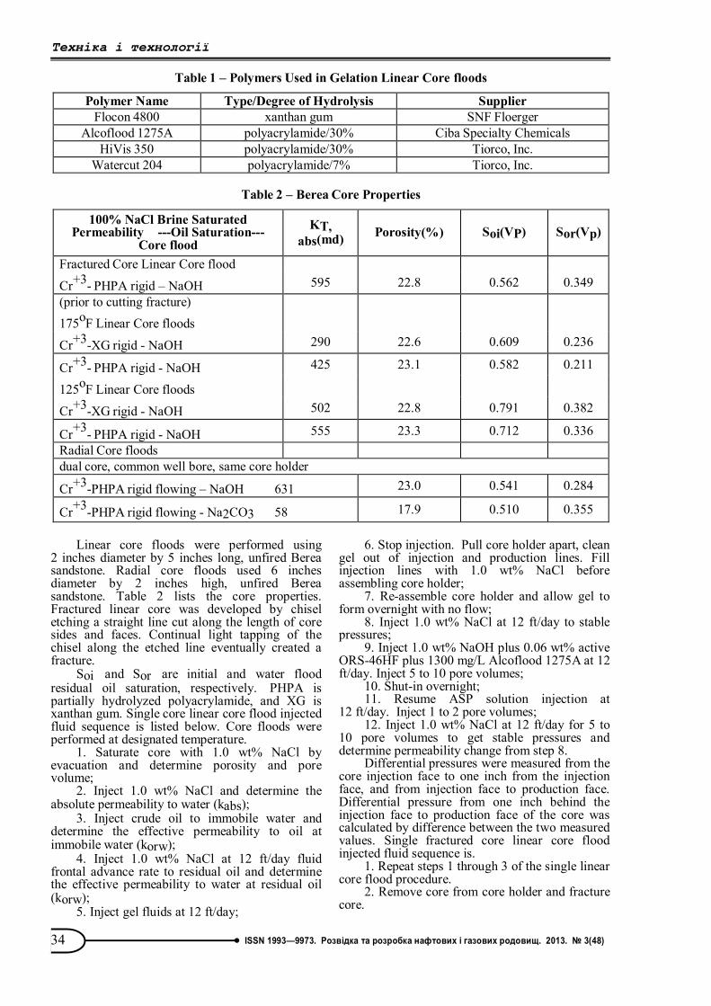
Table 1 – Polymers Used in Gelation Linear Core floods
Polymer Name Type/Degree of Hydrolysis Supplier Flocon 4800 xanthan gum SNF Floerger
Alcoflood 1275A polyacrylamide/30% Ciba Specialty Chemicals HiVis 350 polyacrylamide/30% Tiorco, Inc.
Watercut 204 polyacrylamide/7% Tiorco, Inc.
Table 2 – Berea Core Properties
100% NaCl Brine Saturated Permeability ---Oil Saturation---
Core flood KT,
abs(md) Porosity(%) Soi(VP) Sor(Vp)
Fractured Core Linear Core flood
Cr+3- PHPA rigid – NaOH 595 22.8 0.562 0.349 (prior to cutting fracture) 175oF Linear Core floods
Cr+3-XG rigid - NaOH 290 22.6 0.609 0.236
Cr+3- PHPA rigid - NaOH 425 23.1 0.582 0.211
125oF Linear Core floods
Cr+3-XG rigid - NaOH 502 22.8 0.791 0.382
Cr+3- PHPA rigid - NaOH 555 23.3 0.712 0.336 Radial Core floods dual core, common well bore, same core holder
Cr+3-PHPA rigid flowing – NaOH 631 23.0 0.541 0.284
Cr+3-PHPA rigid flowing - Na2CO3 58 17.9 0.510 0.355
Техніка і технології
35 ISSN 1993—9973. Розвідка та розробка нафтових і газових родовищ. 2013. № 3(48)
3. Place fractured core into core holder. Put overburden pressure on core and inject Big Sinking crude oil and determine korw.
4. Inject crude oil to immobile water at 30 ft/day and determine the effective permeability to oil at immobile water (korw).
5. Inject 1.7 pore volumes of 1.0 wt% NaCl at 4 ft/day fluid frontal advance rate to residual oil and determine kwro.
6. Inject at 4 ft/day 0.5 pore volumes of Marcit gel (7500 mg/L WaterCut 204: 2425 mg/L WaterCut 684 or 250 mg/L Cr+3).
7. Inject 0.05 pore volume of 1.0 wt% NaCl. Stop injection. Clean out injection and production lines. Fill injection lines with 1.0 wt% NaCl. Do not take the core holder apart.
8. Shut-in for two days. 9. Inject 1.0 wt% NaCl at 4 ft/day for 7.4 pore
volumes to get stable pressures, flush gel from core, and get resistance factor.
10. Inject 7.1 pore volumes 1.0 wt% NaOH plus 0.06 wt% active ORS-46HF plus 1300 mg/L Alcoflood 1275A at 4 ft/day.
11. Inject 1.0 wt% NaCl at 4 ft/day for 6.5 pore volumes to get stable pressures and flush ASP-gel from core.
Differential pressures were measured from the core injection face to production face. Dual individual core radial core flood with a common manifold injected fluid sequence is listed below. Separate radial core holders were used in steps 1-3.
1. Saturate core with 1.0 wt% NaCl and determine porosity and pore volume.
2. Inject 1.0 wt% NaCl and determine the absolute permeability to water (kabs).
3. Inject Big Sinking crude oil to immobile water and determine korw. Place core in stacked core radial core holder. A piece of cellulose paper was placed between the cores to facilitate capillary continuity. An O-ring was placed on the outer edge of the cores at their junction that will seal to the annulus edge to facilitate separate collection
of fluids from each core. Place an overburden of 1000 psi on the cores. Stacked core injection steps 4-10 - fluid frontal advance rates are summed height, average porosity, and average diameter for two cores.
4. Stack cores so that a common well bore is present.
5. Inject 1.0 wt% NaCl at 5 ft/day fluid frontal advance rate to residual oil saturation and determine korw for each core.
6. Inject gel fluids at 5 ft/day 0.7 pore volumes of the high permeability core and monitor injection pressure.
7. Inject 0.05 pore volumes of the high permeability core of 1.0 wt% NaCl at 5 ft/day.
8. Stop injection and allow gel to form for two days.
9. Inject 1.0 wt% NaCl at 5 ft/day for 5 pore volumes and determine resistance factor.
10. Inject 1.0 wt% NaOH plus 0.10 wt% active ORS-60HF plus 1300 mg/L Alcoflood 1275A solution at 5ft/day and monitor injection pressure.
11. Inject 1.0 wt% NaCl at 5 ft/day for 5 pore volumes and determine residual resistance factor.
Produced fluids were collected in test tubes on a fraction collector. Resistance factor for all core floods was calculated according to
( / )/
ii
P qRFP q
, where ∆P is differential pressure,
psi, and q is injection rate, ml/hr. Baseline values are after 1.0 wt% NaCl injection at Sorw and before initial chemical injection.
Oil saturation is determined by mass balance of injected and produced fluids. Final oil saturation was cross-checked by extraction of fluids by hot toluene. Gel chemical compositions are listed in Table 3.
Gel solutions were mixed in a 1.0 wt% NaCl solution in an injection tank as a single solution just prior to injection.
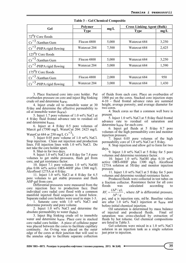
Table 3 – Gel Chemical Compositio
Polymer Cross Linking Agent (Bulk) Gel Type mg/L Type mg/L
72oF Core floods
Cr+3-Xanthan Gum Flocon 4800 5,000 Watercut 684 3,250
Cr+3-PHPA rigid flowing Watercut 204 7,500 Watercut 684 2,425
125oF Core floods
Cr+3-Xanthan Gum Flocon 4800 5,000 Watercut 684 3,250
Cr+3-PHPA rigid flowing Watercut 204 5,000 Watercut 684 1,590
175oF Core floods
Cr+3-Xanthan Gum Flocon 4800 2,000 Watercut 684 950
Cr+3-PHPA rigid flowing Watercut 204 3,000 Watercut 684 1,430
Техніка і технології
36 ISSN 1993—9973. Розвідка та розробка нафтових і газових родовищ. 2013. № 3(48)
Alkaline-Surfactant-Polymer Solutions A 1.0 wt% NaOH plus 0.06 wt% ORS-46HF
plus 1300 mg/L Alcoflood 1275A solution was used with Big Sinking oil in the 72F core floods. ORS-46HF was supplied by OCT, Inc. Interfacial tension between the alkaline-surfactant-polymer solution and Big Sinking crude oil was 0.191 dyne/cm. A 1.0 wt% NaOH plus 0.10 wt% ORS-60HF plus 1300 mg/L Alcoflood 1275A solution was used with the 19.4 API gravity crude oil in the 125F and 175F core floods.
Interfacial tension between the alkaline-surfactant-polymer solution and 19.4 API crude oil was 0.001 dyne/cm.
Results and Discussion Fractured Core Polyacrylamide-Chromium
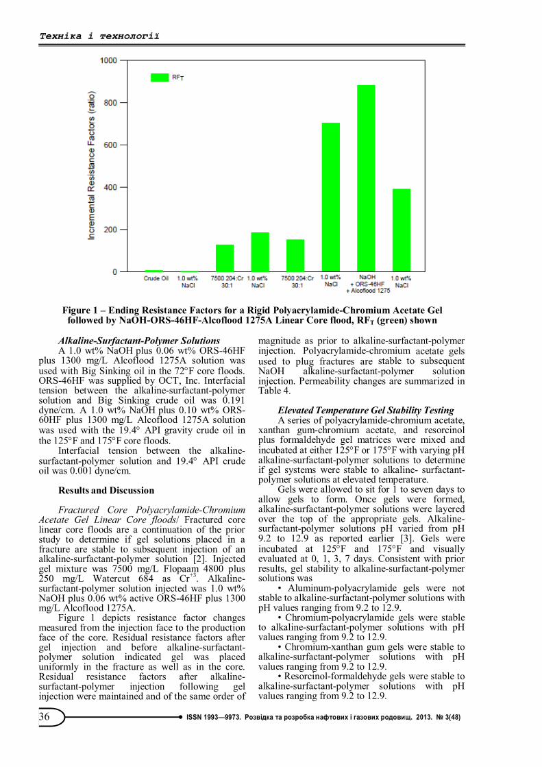
Acetate Gel Linear Core floods/ Fractured core linear core floods are a continuation of the prior study to determine if gel solutions placed in a fracture are stable to subsequent injection of an alkaline-surfactant-polymer solution [2]. Injected gel mixture was 7500 mg/L Flopaam 4800 plus 250 mg/L Watercut 684 as Cr+3. Alkaline-surfactant-polymer solution injected was 1.0 wt% NaOH plus 0.06 wt% active ORS-46HF plus 1300 mg/L Alcoflood 1275A.
Figure 1 depicts resistance factor changes measured from the injection face to the production face of the core. Residual resistance factors after gel injection and before alkaline-surfactant-polymer solution indicated gel was placed uniformly in the fracture as well as in the core. Residual resistance factors after alkaline-surfactant-polymer injection following gel injection were maintained and of the same order of
magnitude as prior to alkaline-surfactant-polymer injection. Polyacrylamide-chromium acetate gels used to plug fractures are stable to subsequent NaOH alkaline-surfactant-polymer solution injection. Permeability changes are summarized in Table 4.
Elevated Temperature Gel Stability Testing A series of polyacrylamide-chromium acetate,
xanthan gum-chromium acetate, and resorcinol plus formaldehyde gel matrices were mixed and incubated at either 125F or 175F with varying pH alkaline-surfactant-polymer solutions to determine if gel systems were stable to alkaline- surfactant-polymer solutions at elevated temperature.
Gels were allowed to sit for 1 to seven days to allow gels to form. Once gels were formed, alkaline-surfactant-polymer solutions were layered over the top of the appropriate gels. Alkaline-surfactant-polymer solutions pH varied from pH 9.2 to 12.9 as reported earlier [3]. Gels were incubated at 125F and 175F and visually evaluated at 0, 1, 3, 7 days. Consistent with prior results, gel stability to alkaline-surfactant-polymer solutions was
• Aluminum-polyacrylamide gels were not stable to alkaline-surfactant-polymer solutions with pH values ranging from 9.2 to 12.9.
• Chromium-polyacrylamide gels were stable to alkaline-surfactant-polymer solutions with pH values ranging from 9.2 to 12.9.
• Chromium-xanthan gum gels were stable to alkaline-surfactant-polymer solutions with pH values ranging from 9.2 to 12.9.
• Resorcinol-formaldehyde gels were stable to alkaline-surfactant-polymer solutions with pH values ranging from 9.2 to 12.9.
Figure 1 – Ending Resistance Factors for a Rigid Polyacrylamide-Chromium Acetate Gel
followed by NaOH-ORS-46HF-Alcoflood 1275A Linear Core flood, RFT (green) shown
Техніка і технології
37 ISSN 1993—9973. Розвідка та розробка нафтових і газових родовищ. 2013. № 3(48)
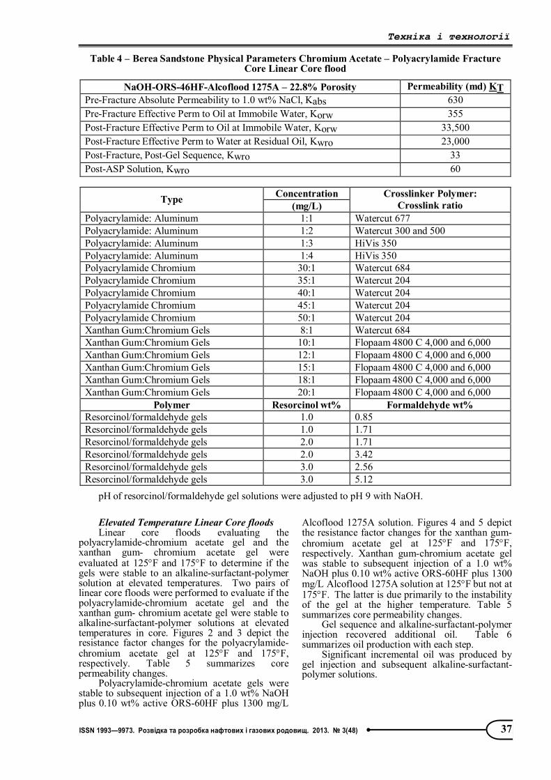
Elevated Temperature Linear Core floods Linear core floods evaluating the
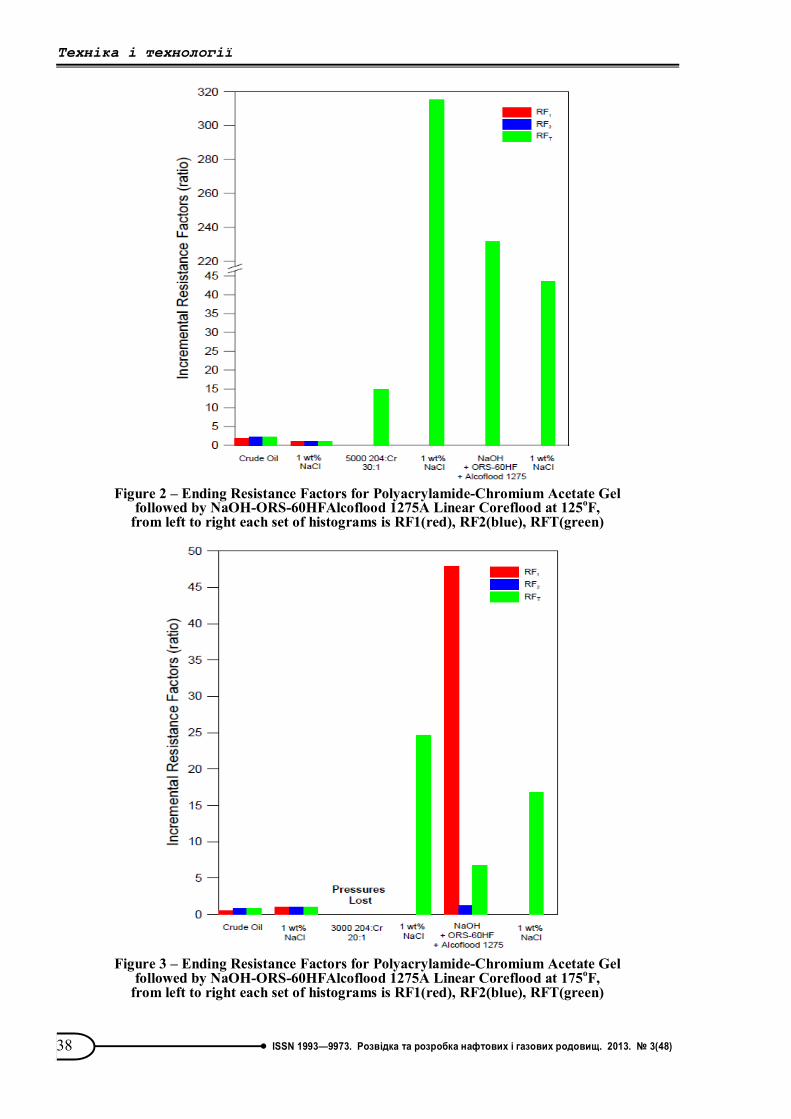
polyacrylamide-chromium acetate gel and the xanthan gum- chromium acetate gel were evaluated at 125F and 175F to determine if the gels were stable to an alkaline-surfactant-polymer solution at elevated temperatures. Two pairs of linear core floods were performed to evaluate if the polyacrylamide-chromium acetate gel and the xanthan gum- chromium acetate gel were stable to alkaline-surfactant-polymer solutions at elevated temperatures in core. Figures 2 and 3 depict the resistance factor changes for the polyacrylamide-chromium acetate gel at 125F and 175F, respectively. Table 5 summarizes core permeability changes.
Polyacrylamide-chromium acetate gels were stable to subsequent injection of a 1.0 wt% NaOH plus 0.10 wt% active ORS-60HF plus 1300 mg/L
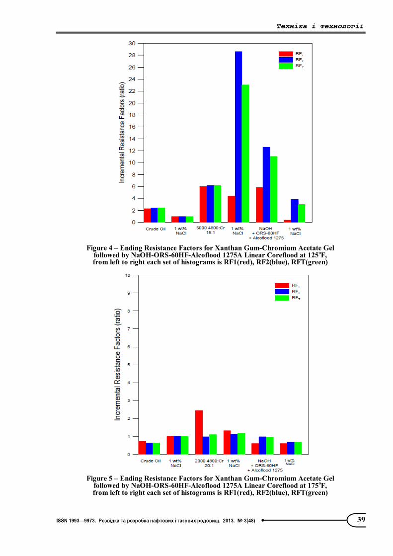
Alcoflood 1275A solution. Figures 4 and 5 depict the resistance factor changes for the xanthan gum-chromium acetate gel at 125F and 175F, respectively. Xanthan gum-chromium acetate gel was stable to subsequent injection of a 1.0 wt% NaOH plus 0.10 wt% active ORS-60HF plus 1300 mg/L Alcoflood 1275A solution at 125F but not at 175F. The latter is due primarily to the instability of the gel at the higher temperature. Table 5 summarizes core permeability changes.
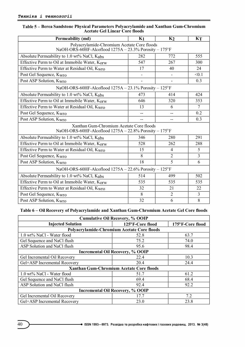
Gel sequence and alkaline-surfactant-polymer injection recovered additional oil. Table 6 summarizes oil production with each step.
Significant incremental oil was produced by gel injection and subsequent alkaline-surfactant- polymer solutions.
Table 4 – Berea Sandstone Physical Parameters Chromium Acetate – Polyacrylamide Fracture Core Linear Core flood
NaOH-ORS-46HF-Alcoflood 1275A – 22.8% Porosity Permeability (md) KT Pre-Fracture Absolute Permeability to 1.0 wt% NaCl, Kabs 630 Pre-Fracture Effective Perm to Oil at Immobile Water, Korw 355 Post-Fracture Effective Perm to Oil at Immobile Water, Korw 33,500 Post-Fracture Effective Perm to Water at Residual Oil, Kwro 23,000 Post-Fracture, Post-Gel Sequence, Kwro 33 Post-ASP Solution, Kwro 60
Concentration Type (mg/L)
Crosslinker Polymer: Crosslink ratio
Polyacrylamide: Aluminum 1:1 Watercut 677 Polyacrylamide: Aluminum 1:2 Watercut 300 and 500 Polyacrylamide: Aluminum 1:3 HiVis 350 Polyacrylamide: Aluminum 1:4 HiVis 350 Polyacrylamide Chromium 30:1 Watercut 684 Polyacrylamide Chromium 35:1 Watercut 204 Polyacrylamide Chromium 40:1 Watercut 204 Polyacrylamide Chromium 45:1 Watercut 204 Polyacrylamide Chromium 50:1 Watercut 204 Xanthan Gum:Chromium Gels 8:1 Watercut 684 Xanthan Gum:Chromium Gels 10:1 Flopaam 4800 C 4,000 and 6,000 Xanthan Gum:Chromium Gels 12:1 Flopaam 4800 C 4,000 and 6,000 Xanthan Gum:Chromium Gels 15:1 Flopaam 4800 C 4,000 and 6,000 Xanthan Gum:Chromium Gels 18:1 Flopaam 4800 C 4,000 and 6,000 Xanthan Gum:Chromium Gels 20:1 Flopaam 4800 C 4,000 and 6,000
Polymer Resorcinol wt% Formaldehyde wt% Resorcinol/formaldehyde gels 1.0 0.85 Resorcinol/formaldehyde gels 1.0 1.71 Resorcinol/formaldehyde gels 2.0 1.71 Resorcinol/formaldehyde gels 2.0 3.42 Resorcinol/formaldehyde gels 3.0 2.56 Resorcinol/formaldehyde gels 3.0 5.12
pH of resorcinol/formaldehyde gel solutions were adjusted to pH 9 with NaOH.
Техніка і технології
38 ISSN 1993—9973. Розвідка та розробка нафтових і газових родовищ. 2013. № 3(48)
Figure 2 – Ending Resistance Factors for Polyacrylamide-Chromium Acetate Gel
followed by NaOH-ORS-60HFAlcoflood 1275A Linear Coreflood at 125oF, from left to right each set of histograms is RF1(red), RF2(blue), RFT(green)
Figure 3 – Ending Resistance Factors for Polyacrylamide-Chromium Acetate Gel
followed by NaOH-ORS-60HFAlcoflood 1275A Linear Coreflood at 175oF, from left to right each set of histograms is RF1(red), RF2(blue), RFT(green)
Техніка і технології
39 ISSN 1993—9973. Розвідка та розробка нафтових і газових родовищ. 2013. № 3(48)
Figure 4 – Ending Resistance Factors for Xanthan Gum-Chromium Acetate Gel
followed by NaOH-ORS-60HF-Alcoflood 1275A Linear Coreflood at 125oF, from left to right each set of histograms is RF1(red), RF2(blue), RFT(green)
Figure 5 – Ending Resistance Factors for Xanthan Gum-Chromium Acetate Gel
followed by NaOH-ORS-60HF-Alcoflood 1275A Linear Coreflood at 175oF, from left to right each set of histograms is RF1(red), RF2(blue), RFT(green)
Техніка і технології
40 ISSN 1993—9973. Розвідка та розробка нафтових і газових родовищ. 2013. № 3(48)
Table 5 – Berea Sandstone Physical Parameters Polyacrylamide and Xanthan Gum-Chromium Acetate Gel Linear Core floods
Permeability (md) K1 K2 KT Polyacrylamide-Chromium Acetate Core floods
NaOH-ORS-60HF-Alcoflood 1275A – 23.3% Porosity – 175F Absolute Permeability to 1.0 wt% NaCl, Kabs 282 772 555 Effective Perm to Oil at Immobile Water, Korw 547 267 300 Effective Perm to Water at Residual Oil, Kwro 17 40 24 Post Gel Sequence, Kwro - - <0.1 Post ASP Solution, Kwro - - 0.3
NaOH-ORS-60HF-Alcoflood 1275A – 23.1% Porosity – 125F Absolute Permeability to 1.0 wt% NaCl, Kabs 473 414 424 Effective Perm to Oil at Immobile Water, Korw 646 320 353 Effective Perm to Water at Residual Oil, Kwro 13 6 7 Post Gel Sequence, Kwro -- -- 0.2 Post ASP Solution, Kwro -- -- 0.3
Xanthan Gum-Chromium Acetate Core floods NaOH-ORS-60HF-Alcoflood 1275A – 22.8% Porosity – 175F
Absolute Permeability to 1.0 wt% NaCl, Kabs 346 280 291 Effective Perm to Oil at Immobile Water, Korw 528 262 288 Effective Perm to Water at Residual Oil, Kwro 15 4 5 Post Gel Sequence, Kwro 8 2 3 Post ASP Solution, Kwro 18 5 6
NaOH-ORS-60HF-Alcoflood 1275A – 22.6% Porosity – 125F Absolute Permeability to 1.0 wt% NaCl, Kabs 514 499 502 Effective Perm to Oil at Immobile Water, Korw 535 535 535 Effective Perm to Water at Residual Oil, Kwro 32 21 22 Post Gel Sequence, Kwro 8 2 3 Post ASP Solution, Kwro 32 6 8
Table 6 – Oil Recovery of Polyacrylamide and Xanthan Gum-Chromium Acetate Gel Core floods
Cumulative Oil Recovery, % OOIP Injected Solution 125F-Core flood 175F-Core flood
Polyacrylamide-Chromium Acetate Core floods 1.0 wt% NaCl - Water flood 52.8 63.7 Gel Sequence and NaCl flush 75.2 74.0 ASP Solution and NaCl flush 95.6 98.4
Incremental Oil Recovery, % OOIP Gel Incremental Oil Recovery 22.4 10.3 Gel+ASP Incremental Recovery 20.4 24.4
Xanthan Gum-Chromium Acetate Core floods 1.0 wt% NaCl - Water flood 51.7 61.2 Gel Sequence and NaCl flush 69.4 68.4 ASP Solution and NaCl flush 92.4 92.2
Incremental Oil Recovery, % OOIP Gel Incremental Oil Recovery 17.7 7.2 Gel+ASP Incremental Recovery 23.0 23.8
Техніка і технології
41 ISSN 1993—9973. Розвідка та розробка нафтових і газових родовищ. 2013. № 3(48)
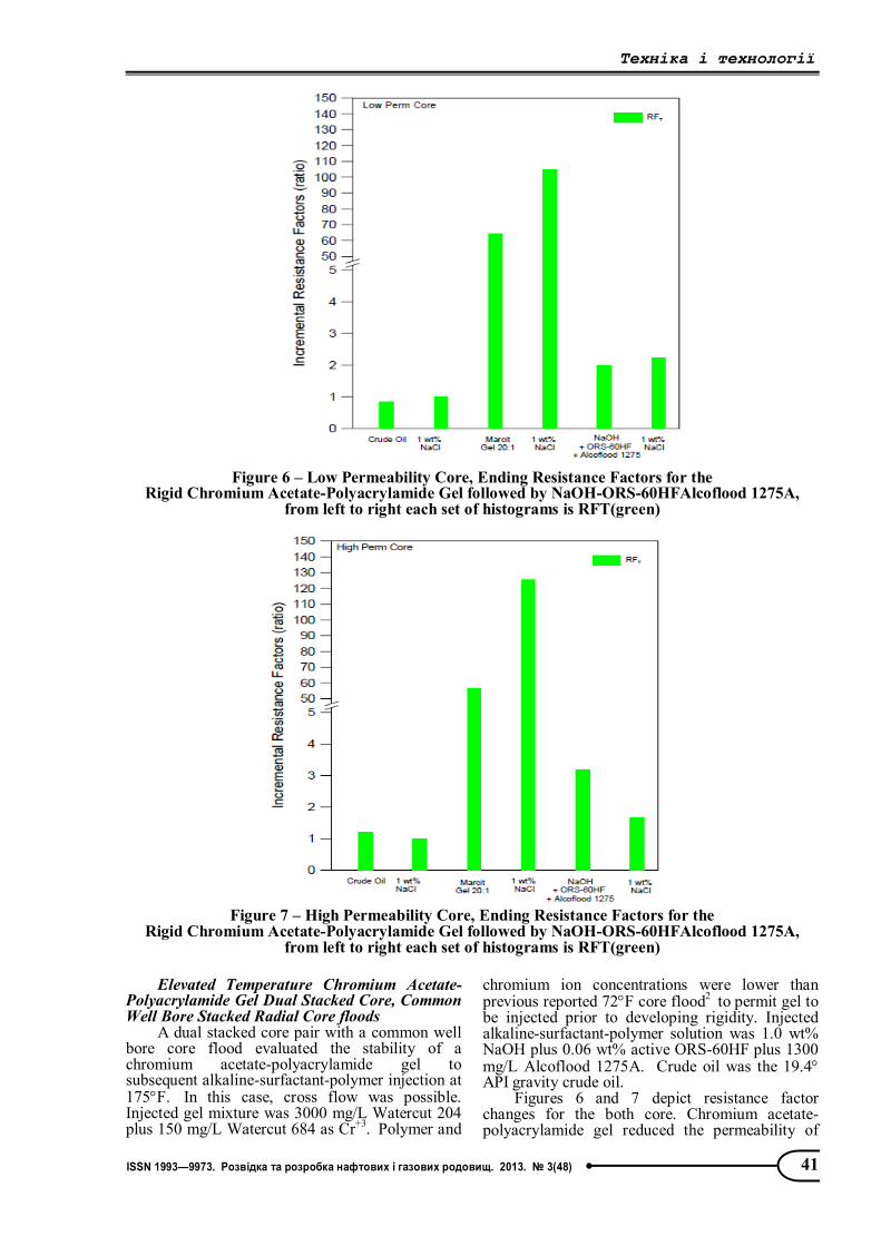
Elevated Temperature Chromium Acetate-Polyacrylamide Gel Dual Stacked Core, Common Well Bore Stacked Radial Core floods
A dual stacked core pair with a common well bore core flood evaluated the stability of a chromium acetate-polyacrylamide gel to subsequent alkaline-surfactant-polymer injection at 175F. In this case, cross flow was possible. Injected gel mixture was 3000 mg/L Watercut 204 plus 150 mg/L Watercut 684 as Cr+3. Polymer and
chromium ion concentrations were lower than previous reported 72F core flood2 to permit gel to be injected prior to developing rigidity. Injected alkaline-surfactant-polymer solution was 1.0 wt% NaOH plus 0.06 wt% active ORS-60HF plus 1300 mg/L Alcoflood 1275A. Crude oil was the 19.4 API gravity crude oil.
Figures 6 and 7 depict resistance factor changes for the both core. Chromium acetate-polyacrylamide gel reduced the permeability of
Figure 6 – Low Permeability Core, Ending Resistance Factors for the
Rigid Chromium Acetate-Polyacrylamide Gel followed by NaOH-ORS-60HFAlcoflood 1275A, from left to right each set of histograms is RFT(green)
Figure 7 – High Permeability Core, Ending Resistance Factors for the
Rigid Chromium Acetate-Polyacrylamide Gel followed by NaOH-ORS-60HFAlcoflood 1275A, from left to right each set of histograms is RFT(green)
Техніка і технології
42 ISSN 1993—9973. Розвідка та розробка нафтових і газових родовищ. 2013. № 3(48)
each core with the high permeability core permeability reduction being slightly greater during and after gel injection. Permeability changes were maintained after alkaline-surfactant-polymer injection but not to the same degree as previously reported possibly due to injection of a more fluid gel and gel syneresis. Permeability
changes for dual, stacked core chromium acetate-polyacrylamide core flood are summarized in Table 7.
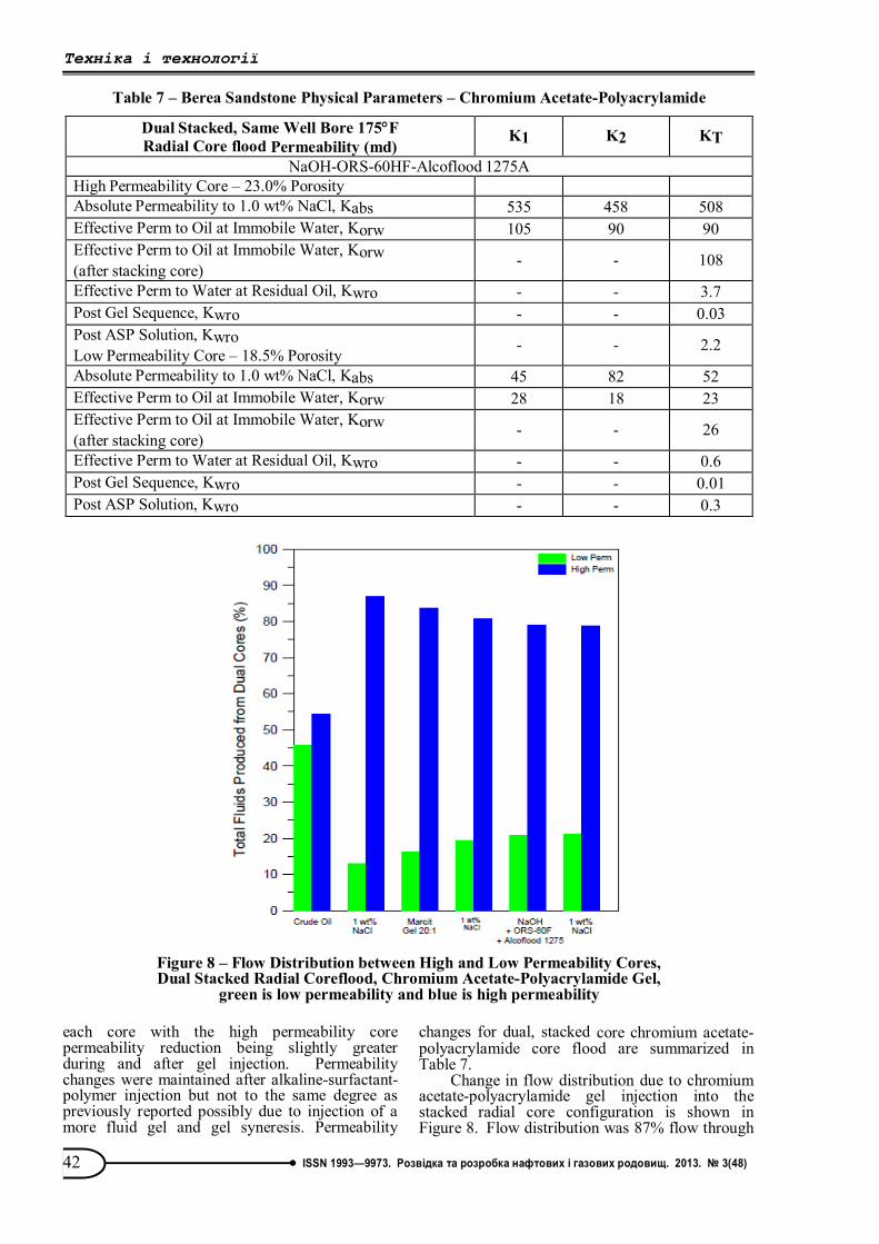
Change in flow distribution due to chromium acetate-polyacrylamide gel injection into the stacked radial core configuration is shown in Figure 8. Flow distribution was 87% flow through
Table 7 – Berea Sandstone Physical Parameters – Chromium Acetate-Polyacrylamide
Dual Stacked, Same Well Bore 175F Radial Core flood Permeability (md)
K1 K2 KT
NaOH-ORS-60HF-Alcoflood 1275A High Permeability Core – 23.0% Porosity Absolute Permeability to 1.0 wt% NaCl, Kabs 535 458 508 Effective Perm to Oil at Immobile Water, Korw 105 90 90 Effective Perm to Oil at Immobile Water, Korw (after stacking core) - - 108
Effective Perm to Water at Residual Oil, Kwro - - 3.7 Post Gel Sequence, Kwro - - 0.03 Post ASP Solution, Kwro Low Permeability Core – 18.5% Porosity - - 2.2
Absolute Permeability to 1.0 wt% NaCl, Kabs 45 82 52 Effective Perm to Oil at Immobile Water, Korw 28 18 23 Effective Perm to Oil at Immobile Water, Korw (after stacking core) - - 26
Effective Perm to Water at Residual Oil, Kwro - - 0.6 Post Gel Sequence, Kwro - - 0.01 Post ASP Solution, Kwro - - 0.3
Figure 8 – Flow Distribution between High and Low Permeability Cores, Dual Stacked Radial Coreflood, Chromium Acetate-Polyacrylamide Gel,
green is low permeability and blue is high permeability
Техніка і технології
43 ISSN 1993—9973. Розвідка та розробка нафтових і газових родовищ. 2013. № 3(48)
the high permeability core during initial water flood. Flow distribution was reduced to 80% through the high permeability core during the water flush subsequent to gel placement, indicating gel was diverting injected water from the high permeability core into the low permeability core. Injected alkaline- surfactant-polymer solution did not alter the flow distribution.
Oil recoveries from the chromium acetate- polyacrylamide gel stacked radial flood are summarized in Table 8. Incremental oil was produced during gel injection from each core.
Alkaline-surfactant-polymer injection produced a significant volume of incremental oil from both core.
Numerical Simulation of a Crosslink-
Alkaline-Surfactant-Polymer Flood A Minnelusa reservoir with an «A» sand and
a «B» sand with common production and injection wells was simulated to demonstrate improvement of oil recovery after gel treatment followed by an alkaline-surfactant-polymer flood. A and B sands are separated by a shale layer. GCOMP numerical simulation software was used [4]. GCOMP is a black oil numerical simulation package with a chemical flood option.
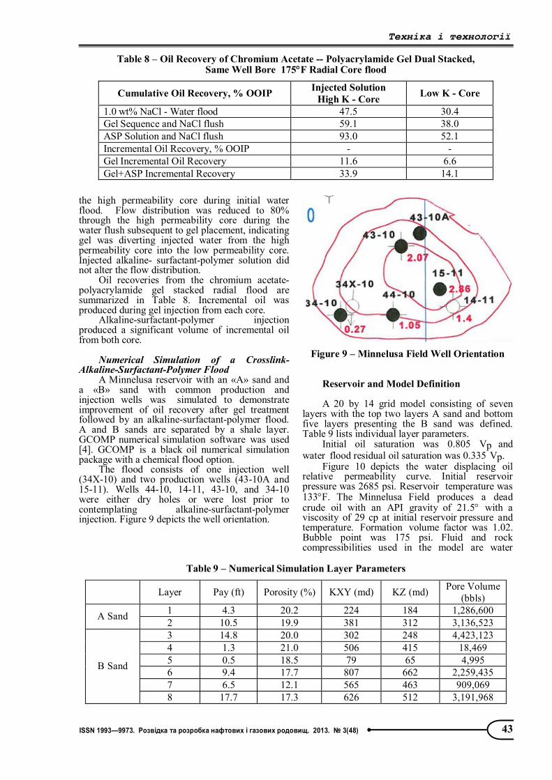
The flood consists of one injection well (34X-10) and two production wells (43-10A and 15-11). Wells 44-10, 14-11, 43-10, and 34-10 were either dry holes or were lost prior to contemplating alkaline-surfactant-polymer injection. Figure 9 depicts the well orientation.
Figure 9 – Minnelusa Field Well Orientation
Reservoir and Model Definition A 20 by 14 grid model consisting of seven
layers with the top two layers A sand and bottom five layers presenting the B sand was defined. Table 9 lists individual layer parameters.
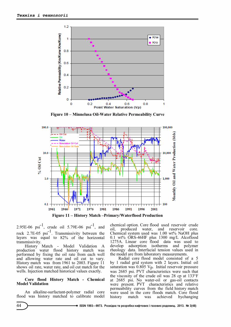
Initial oil saturation was 0.805 Vp and water flood residual oil saturation was 0.335 Vp.
Figure 10 depicts the water displacing oil relative permeability curve. Initial reservoir pressure was 2685 psi. Reservoir temperature was 133F. The Minnelusa Field produces a dead crude oil with an API gravity of 21.5 with a viscosity of 29 cp at initial reservoir pressure and temperature. Formation volume factor was 1.02. Bubble point was 175 psi. Fluid and rock compressibilities used in the model are water
Table 8 – Oil Recovery of Chromium Acetate -- Polyacrylamide Gel Dual Stacked, Same Well Bore 175F Radial Core flood
Cumulative Oil Recovery, % OOIP Injected Solution High K - Core Low K - Core
1.0 wt% NaCl - Water flood 47.5 30.4 Gel Sequence and NaCl flush 59.1 38.0 ASP Solution and NaCl flush 93.0 52.1 Incremental Oil Recovery, % OOIP - - Gel Incremental Oil Recovery 11.6 6.6 Gel+ASP Incremental Recovery 33.9 14.1
Table 9 – Numerical Simulation Layer Parameters
Layer Pay (ft) Porosity (%) KXY (md) KZ (md) Pore Volume (bbls)
1 4.3 20.2 224 184 1,286,600 A Sand 2 10.5 19.9 381 312 3,136,523 3 14.8 20.0 302 248 4,423,123 4 1.3 21.0 506 415 18,469 5 0.5 18.5 79 65 4,995 6 9.4 17.7 807 662 2,259,435 7 6.5 12.1 565 463 909,069
B Sand
8 17.7 17.3 626 512 3,191,968
Техніка і технології
44 ISSN 1993—9973. Розвідка та розробка нафтових і газових родовищ. 2013. № 3(48)
2.95E-06 psi-1, crude oil 5.79E-06 psi-1, and rock 2.7E-05 psi-1. Transmissivity between the layers was equal to 82% of the horizontal transmissivity.
History Match - Model Validation A production water flood history match was performed by fixing the oil rate from each well and allowing water rate and oil cut to vary. History match was from 1961 to 2003. Figure 11 shows oil rate, water rate, and oil cut match for the wells. Injection matched historical values exactly.
Core flood History Match - Chemical
Model Validation An alkaline-surfactant-polymer radial core
flood was history matched to calibrate model
chemical option. Core flood used reservoir crude oil, produced water, and reservoir core. Chemical system used was 1.00 wt% NaOH plus 0.1 wt% ORS-46HF plus 1300 mg/L Alcoflood 1275A. Linear core flood data was used to develop adsorption isotherms and polymer rheology data. Interfacial tension values used in the model are from laboratory measurements.
Radial core flood model consisted of a 5 by 1 radial grid system with 2 layers. Initial oil saturation was 0.805 Vp. Initial reservoir pressure was 2685 psi. PVT characteristics were such that the viscosity of the crude oil was 28 cp at 133F at 2685 psi. No water-oil or gas-oil contacts were present. PVT characteristics and relative permeability curves from the field history match were used in the core floods match. Core flood history match was achieved bychanging
Figure 10 – Minnelusa Oil-Water Relative Permeability Curve
Figure 11 – History Match –Primary/Waterflood Production

Техніка і технології
45 ISSN 1993—9973. Розвідка та розробка нафтових і газових родовищ. 2013. № 3(48)
permeability and capillary number desideration curve. Final permeability distribution was 14 md for both layers. This compares to 13.6 and 16.3 md for the effective permeability to oil and effective permeability to water, respectively. Figure 12 shows the capillary de-saturation curve required to match the core flood. Note, the capillary number - desideration correlation matched core flood values during water flood. As capillary number increased due to chemical injection, linear core flood data facilitated a match better than radial core flood data.
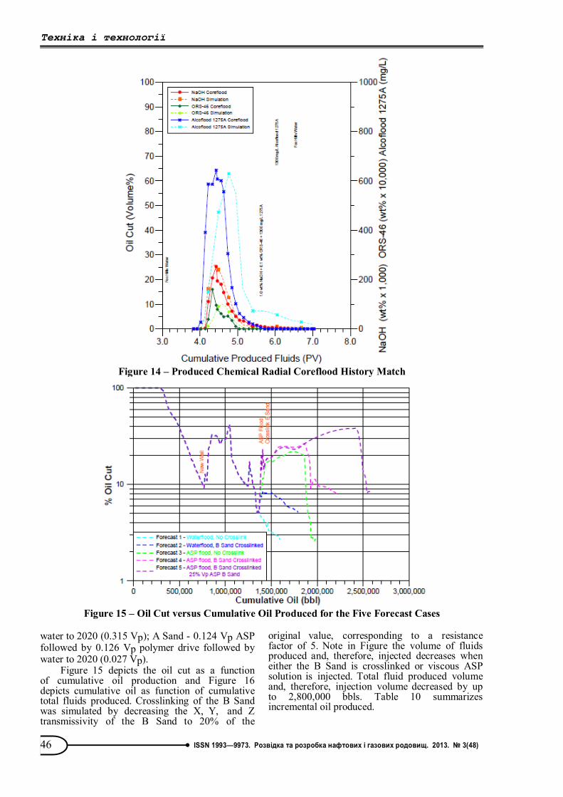
Figures 13 and 14 show oil recovery and oil cut history match, and produced chemical match for the alkaline-surfactant-polymer radial core flood. Both the water flood and chemical flood oil recoveries are duplicated by the numerical simulation indicating the relative permeability and capillary number calculation accurately depict the water flood and the alkaline-surfactant- polymer flood for the Minnelusa oil, water, and rock system. Produced chemicals were similarly matched.
Alkaline-Polymer and Alkaline-Surfactant-Polymer Forecasts
Five forecasts were made: 1. Water flood through 2020; 2. Crosslink B Sand in 2003 followed by
water through 2020; 3. No Crosslink, ASP Flood: B Sand - 0.262
Vp ASP followed by 0.278 Vp polymer drive followed by water to 2020 (0.972 Vp); A Sand - 0.024 Vp ASP followed by 0.076 Vp polymer drive followed by water to 2020 (0.049 Vp);
4. Crosslink B Sand and inject chemical over the same time as case 3: B Sand - 0.091 Vp ASP followed by 0.110 Vp polymer drive followed by water to 2020 (0.885 Vp); A Sand - 0.036 Vp ASP followed by 0.098 Vp polymer drive followed by water to 2020 (0.087 Vp);
5. Crosslink B Sand and inject chemical until approximately 0.25 Vp of ASP solution has been injected into the B Sand: B Sand - 0.239 Vp ASP followed by 0.152 Vp polymer drive followed by
Figure 12 – Oil Saturation Reduction versus log Capillary Number
Figure 13 – Oil Cut and Cumulative Oil Recovery Radial Coreflood History Match
Техніка і технології
46 ISSN 1993—9973. Розвідка та розробка нафтових і газових родовищ. 2013. № 3(48)
water to 2020 (0.315 Vp); A Sand - 0.124 Vp ASP followed by 0.126 Vp polymer drive followed by water to 2020 (0.027 Vp).
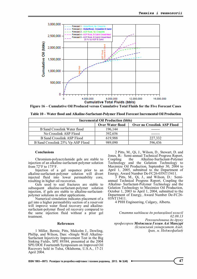
Figure 15 depicts the oil cut as a function of cumulative oil production and Figure 16 depicts cumulative oil as function of cumulative total fluids produced. Crosslinking of the B Sand was simulated by decreasing the X, Y, and Z transmissivity of the B Sand to 20% of the
original value, corresponding to a resistance factor of 5. Note in Figure the volume of fluids produced and, therefore, injected decreases when either the B Sand is crosslinked or viscous ASP solution is injected. Total fluid produced volume and, therefore, injection volume decreased by up to 2,800,000 bbls. Table 10 summarizes incremental oil produced.
Figure 14 – Produced Chemical Radial Coreflood History Match
Figure 15 – Oil Cut versus Cumulative Oil Produced for the Five Forecast Cases
Техніка і технології
47 ISSN 1993—9973. Розвідка та розробка нафтових і газових родовищ. 2013. № 3(48)
Conclusions Chromium-polyacrylamide gels are stable to
injection of an alkaline-surfactant-polymer solution from 72F to 175F.
Injection of a gel sequence prior to an alkaline-surfactant-polymer solution will divert injected fluid into lower permeability core, resulting in higher oil recoveries.
Gels used to seal fractures are stable to subsequent alkaline-surfactant-polymer solution injection, if gels are stable to alkaline-surfactant-polymer solutions in other applications.
Numerical simulation indicates placement of a gel into a higher permeability section of a reservoir will improve water flood recovery and alkaline-surfactant-polymer flood oil recovery compared to the same injection fluid without a prior gel treatment.
References
1 Miller, Bernie, Pitts, Malcolm J., Dowling,
Phillip, and Wilson, Dan: «Single Well Alkaline-Surfactant Injectivity Improvement Test in the Big Sinking Field», SPE 89384, presented at the 2004 SPE/DOE Fourteenth Symposium on Improved Oil Recovery held in Tulsa, Oklahoma, U.S.A., 17-21 April 2004.
2 Pitts, M., Qi, J., Wilson, D., Stewart, D. and Jones, B.: Semi-annual Technical Progress Report, Coupling the Alkaline-Surfactant-Polymer Technology and the Gelation Technology to Maximize Oil Production, September 30, 2004 to April 1, 2005, submitted to the Department of Energy, Award Number De-FC26-03NT15411.
3 Pitts, M., Qi, J., and Wilson, D.: Semi-annual Technical Progress Report, Coupling the Alkaline- Surfactant-Polymer Technology and the Gelation Technology to Maximize Oil Production, October 1, 2003 to April 1, 2004, submitted to the Department of Energy, Award Number De-FC26-03NT15411.
4 PHH Engineering, Calgary, Alberta.
Стаття надійшла до редакційної колегії 02.09.13
Рекомендована до друку професором Меджлиса Голам Алі Мансурі
(Ісламський університет Азад, Іран, м. Неджефабад)
Figure 16 – Cumulative Oil Produced versus Cumulative Total Fluids for the Five Forecast Cases
Table 10 – Water flood and Alkaline-Surfactant-Polymer Flood Forecast Incremental Oil Production
Incremental Oil Production (bbls) Over Water flood Over no Crosslink ASP Flood
B Sand Crosslink Water flood 196,144 ------- No Crosslink ASP Flood 392,656 -------
B Sand Crosslink ASP Flood 619,988 227,332 B Sand Crosslink 25% Vp ASP Flood 989,090 596,436