Embed Size (px)
Citation preview
On -Line UPS with Low Frequency Transformer for Isolation
Husham Idan Hussein
Electrical Power and Machines Engineering College of Engineering
Diyala University Diyala. Iraq.
[email protected] Abstract- This paper addressed the design of online uninterruptible power supply (UPS) system with a low frequency transformer for isolation, based on given specifications which include bypass switch and battery and taken into account the concentrated on open loop operation. Depending on the application, the online UPS system is composed by two stage conversions of AC/DC and DC/AC, the enclosure of these freeloading effects of all components and devices is very important to design the UPS system for acceptable performance. The initial stage of the design is based on the theoretical calculations and few assumptions have been made throughout the design. Simulation work has been carried out by MATLAB/Simulink program to validate the operation of the online UPS system with low frequency transformer isolation. The analysis of the results are presented and the justifications with regards to performance evaluation parameters which some are not satisfied the design specifications are discussed in details. Index Terms-- Uninterruptible power supplies, power electronic converters, rectifiers, integrated converters, Battery charger, inverters, modeling and analysis.
I. INTRODUCTION The online UPS is normally applied for
environments where electrical isolation is necessary or for a very sensitive to power fluctuations equipments. The online UPS typically costs much more, due to it having a much greater current AC-to-DC battery-charger/rectifier, and with the rectifier and inverter designed to run continuously with improved cooling systems “Ref. [1]”. The online power supply gets its name from the fact that the input line power is not connected to the output during normal operation. Instead, the input power first goes through an AC to DC converter where the DC voltage is used to charge the UPS' main battery. The battery then, in turn, is discharging through a DC to AC inverter and routed through a transfer switch for the output voltage. This process can be referred to as a double conversion of the input power “Ref. [2]”.The major- advantage of online UPS is the total isolation between the input line
voltage and the output voltage. Another advantage is its switching time when the input line power fails. In this case, the switching time is non-existent. The only component that fails during the outage is the charger for the battery. Generally the Uninterruptible power systems (UPS) provides total independence between input and output voltage amplitude and frequency, and, thus, high output voltage quality can be obtained “Ref. [3]”.
This allows there to be zero interruption when a power failure occurs. A disadvantage to the online UPS is the large amount of power consumed caused by the double conversion process. This power consumption caused heat loss and greatly affects the system’s efficiency. The double conversion also needs to occur constantly “Ref. [4, 5]”. Therefore, the reliability of components used to create the charger; rectifier, inverter and the type of battery used have to be of a higher quality. This increased the cost of these types of units up very high compared to the lower quality back-up UPS. Fig. 1 is a simplified block diagram of the online UPS with low frequency isolating transformer. “Ref. [6]”
Iraq J. Electrical and Electronic Engineeringالمجلة العراقية للهندسة الكهربائية وااللكترونية ، العدد 10مجلد 2 ، 2014 Vol.10 No.2 , 2014
100
ACLine
AC/DCRectifier/Charger
Battery Discharge
Unit
BatteryBank
DC/ACInverter
Load
Low FrequencyIsolating
Transformer
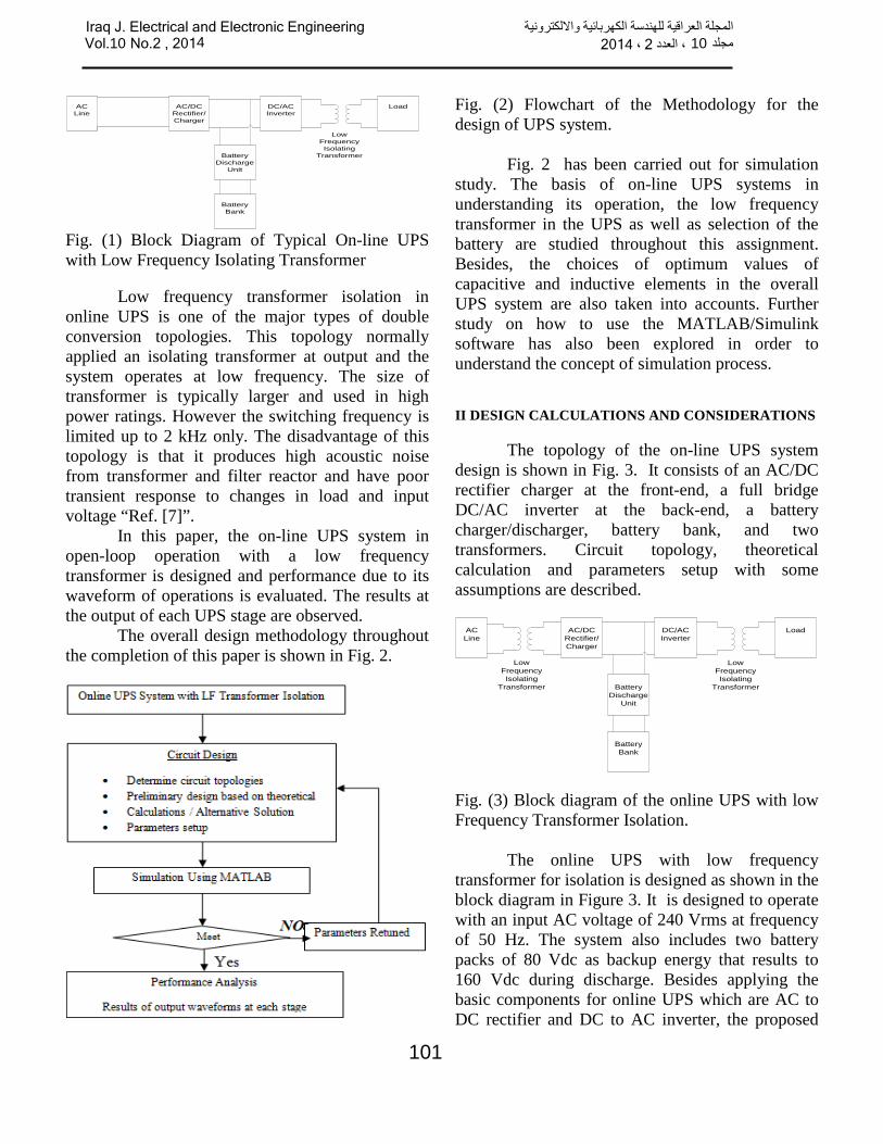
Fig. (1) Block Diagram of Typical On-line UPS with Low Frequency Isolating Transformer
Low frequency transformer isolation in online UPS is one of the major types of double conversion topologies. This topology normally applied an isolating transformer at output and the system operates at low frequency. The size of transformer is typically larger and used in high power ratings. However the switching frequency is limited up to 2 kHz only. The disadvantage of this topology is that it produces high acoustic noise from transformer and filter reactor and have poor transient response to changes in load and input voltage “Ref. [7]”.
In this paper, the on-line UPS system in open-loop operation with a low frequency transformer is designed and performance due to its waveform of operations is evaluated. The results at the output of each UPS stage are observed.
The overall design methodology throughout the completion of this paper is shown in Fig. 2.
Fig. (2) Flowchart of the Methodology for the design of UPS system.
Fig. 2 has been carried out for simulation study. The basis of on-line UPS systems in understanding its operation, the low frequency transformer in the UPS as well as selection of the battery are studied throughout this assignment. Besides, the choices of optimum values of capacitive and inductive elements in the overall UPS system are also taken into accounts. Further study on how to use the MATLAB/Simulink software has also been explored in order to understand the concept of simulation process. II DESIGN CALCULATIONS AND CONSIDERATIONS
The topology of the on-line UPS system design is shown in Fig. 3. It consists of an AC/DC rectifier charger at the front-end, a full bridge DC/AC inverter at the back-end, a battery charger/discharger, battery bank, and two transformers. Circuit topology, theoretical calculation and parameters setup with some assumptions are described.
ACLine
AC/DCRectifier/Charger
Battery Discharge
Unit
BatteryBank
DC/ACInverter
Load
Low FrequencyIsolating
Transformer
Low FrequencyIsolating
Transformer
Fig. (3) Block diagram of the online UPS with low Frequency Transformer Isolation.
The online UPS with low frequency transformer for isolation is designed as shown in the block diagram in Figure 3. It is designed to operate with an input AC voltage of 240 Vrms at frequency of 50 Hz. The system also includes two battery packs of 80 Vdc as backup energy that results to 160 Vdc during discharge. Besides applying the basic components for online UPS which are AC to DC rectifier and DC to AC inverter, the proposed
Iraq J. Electrical and Electronic Engineeringالمجلة العراقية للهندسة الكهربائية وااللكترونية ، العدد 10مجلد 2 ، 2014 Vol.10 No.2 , 2014
101
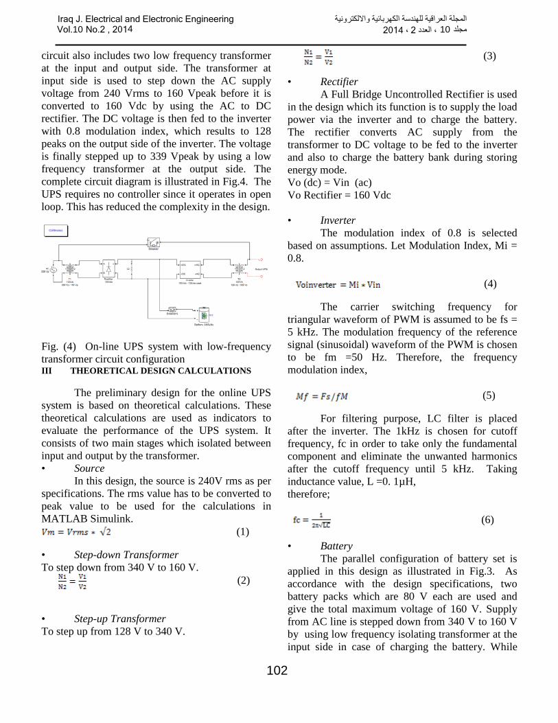
circuit also includes two low frequency transformer at the input and output side. The transformer at input side is used to step down the AC supply voltage from 240 Vrms to 160 Vpeak before it is converted to 160 Vdc by using the AC to DC rectifier. The DC voltage is then fed to the inverter with 0.8 modulation index, which results to 128 peaks on the output side of the inverter. The voltage is finally stepped up to 339 Vpeak by using a low frequency transformer at the output side. The complete circuit diagram is illustrated in Fig.4. The UPS requires no controller since it operates in open loop. This has reduced the complexity in the design.
Fig. (4) On-line UPS system with low-frequency transformer circuit configuration III THEORETICAL DESIGN CALCULATIONS
The preliminary design for the online UPS system is based on theoretical calculations. These theoretical calculations are used as indicators to evaluate the performance of the UPS system. It consists of two main stages which isolated between input and output by the transformer. • Source
In this design, the source is 240V rms as per specifications. The rms value has to be converted to peak value to be used for the calculations in MATLAB Simulink.
(1)
• Step-down Transformer To step down from 340 V to 160 V. (2)
• Step-up Transformer To step up from 128 V to 340 V.
(3)
• Rectifier A Full Bridge Uncontrolled Rectifier is used
in the design which its function is to supply the load power via the inverter and to charge the battery. The rectifier converts AC supply from the transformer to DC voltage to be fed to the inverter and also to charge the battery bank during storing energy mode. Vo (dc) = Vin (ac) Vo Rectifier = 160 Vdc • Inverter
The modulation index of 0.8 is selected based on assumptions. Let Modulation Index, Mi = 0.8. (4)
The carrier switching frequency for triangular waveform of PWM is assumed to be fs = 5 kHz. The modulation frequency of the reference signal (sinusoidal) waveform of the PWM is chosen to be fm =50 Hz. Therefore, the frequency modulation index, (5)
For filtering purpose, LC filter is placed after the inverter. The 1kHz is chosen for cutoff frequency, fc in order to take only the fundamental component and eliminate the unwanted harmonics after the cutoff frequency until 5 kHz. Taking inductance value, L =0. 1µH, therefore; (6)
• Battery The parallel configuration of battery set is
applied in this design as illustrated in Fig.3. As accordance with the design specifications, two battery packs which are 80 V each are used and give the total maximum voltage of 160 V. Supply from AC line is stepped down from 340 V to 160 V by using low frequency isolating transformer at the input side in case of charging the battery. While
Iraq J. Electrical and Electronic Engineeringالمجلة العراقية للهندسة الكهربائية وااللكترونية ، العدد 10مجلد 2 ، 2014 Vol.10 No.2 , 2014
102
during a backup operation, the battery will take over the AC line’s function to supply the power to the load via inverter. The low frequency isolating transformer at the output side will step up the voltage output of the inverter from 128V to 340V. IV RESULTS AND DISCUSSION
A- UPS Design without load
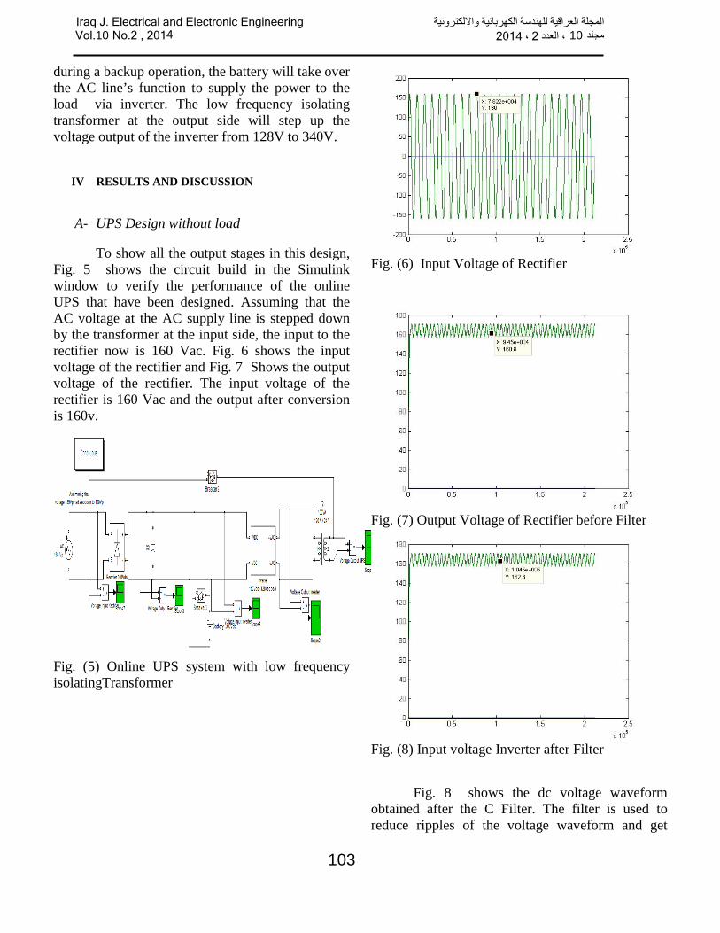
To show all the output stages in this design, Fig. 5 shows the circuit build in the Simulink window to verify the performance of the online UPS that have been designed. Assuming that the AC voltage at the AC supply line is stepped down by the transformer at the input side, the input to the rectifier now is 160 Vac. Fig. 6 shows the input voltage of the rectifier and Fig. 7 Shows the output voltage of the rectifier. The input voltage of the rectifier is 160 Vac and the output after conversion is 160v.
Fig. (5) Online UPS system with low frequency isolatingTransformer
Fig. (6) Input Voltage of Rectifier
Fig. (7) Output Voltage of Rectifier before Filter
Fig. (8) Input voltage Inverter after Filter
Fig. 8 shows the dc voltage waveform obtained after the C Filter. The filter is used to reduce ripples of the voltage waveform and get
Iraq J. Electrical and Electronic Engineeringالمجلة العراقية للهندسة الكهربائية وااللكترونية ، العدد 10مجلد 2 ، 2014 Vol.10 No.2 , 2014
103
smoother signals. The output voltage of the rectifier before it is filtered has a high Percentage of ripple which is 8%. After it is filtered, the ripple reduced to 7.3%.
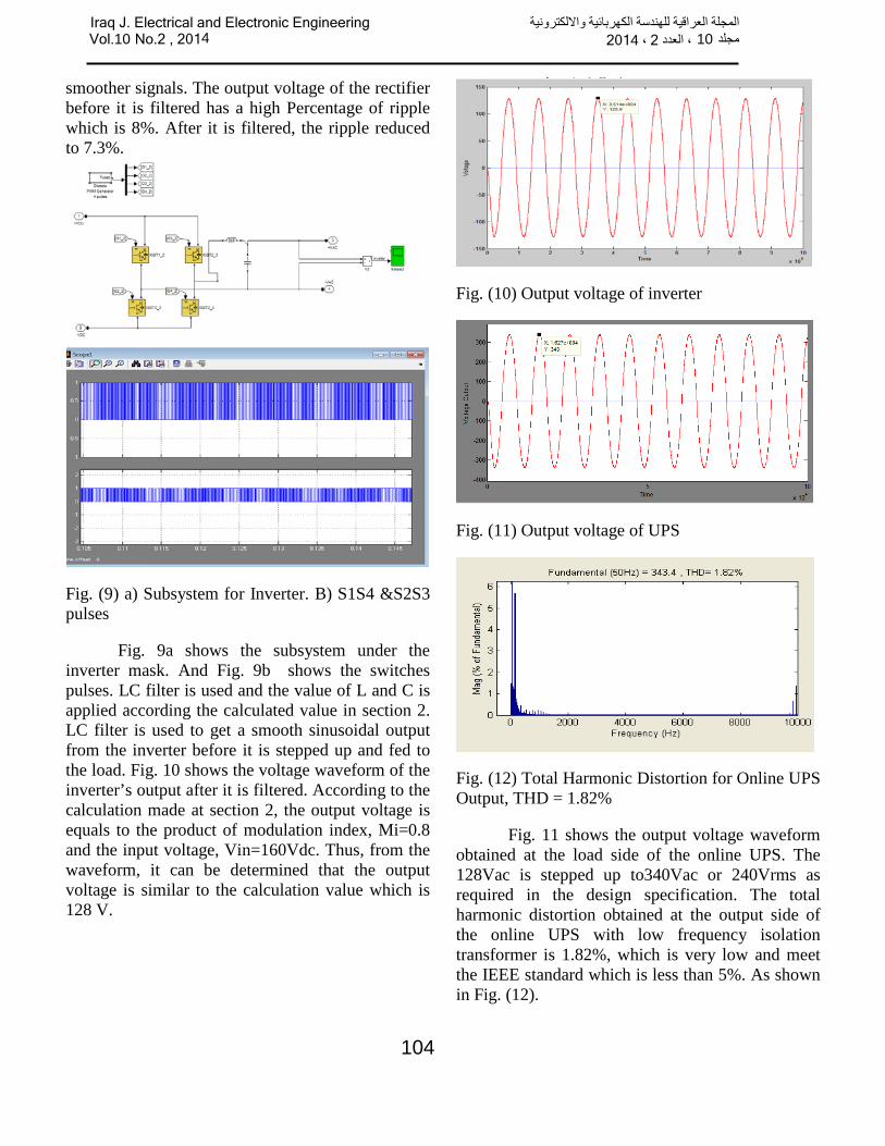
Fig. (9) a) Subsystem for Inverter. B) S1S4 &S2S3 pulses
Fig. 9a shows the subsystem under the inverter mask. And Fig. 9b shows the switches pulses. LC filter is used and the value of L and C is applied according the calculated value in section 2. LC filter is used to get a smooth sinusoidal output from the inverter before it is stepped up and fed to the load. Fig. 10 shows the voltage waveform of the inverter’s output after it is filtered. According to the calculation made at section 2, the output voltage is equals to the product of modulation index, Mi=0.8 and the input voltage, Vin=160Vdc. Thus, from the waveform, it can be determined that the output voltage is similar to the calculation value which is 128 V.
Fig. (10) Output voltage of inverter
Fig. (11) Output voltage of UPS
Fig. (12) Total Harmonic Distortion for Online UPS Output, THD = 1.82%
Fig. 11 shows the output voltage waveform obtained at the load side of the online UPS. The 128Vac is stepped up to340Vac or 240Vrms as required in the design specification. The total harmonic distortion obtained at the output side of the online UPS with low frequency isolation transformer is 1.82%, which is very low and meet the IEEE standard which is less than 5%. As shown in Fig. (12).
Iraq J. Electrical and Electronic Engineeringالمجلة العراقية للهندسة الكهربائية وااللكترونية ، العدد 10مجلد 2 ، 2014 Vol.10 No.2 , 2014
104
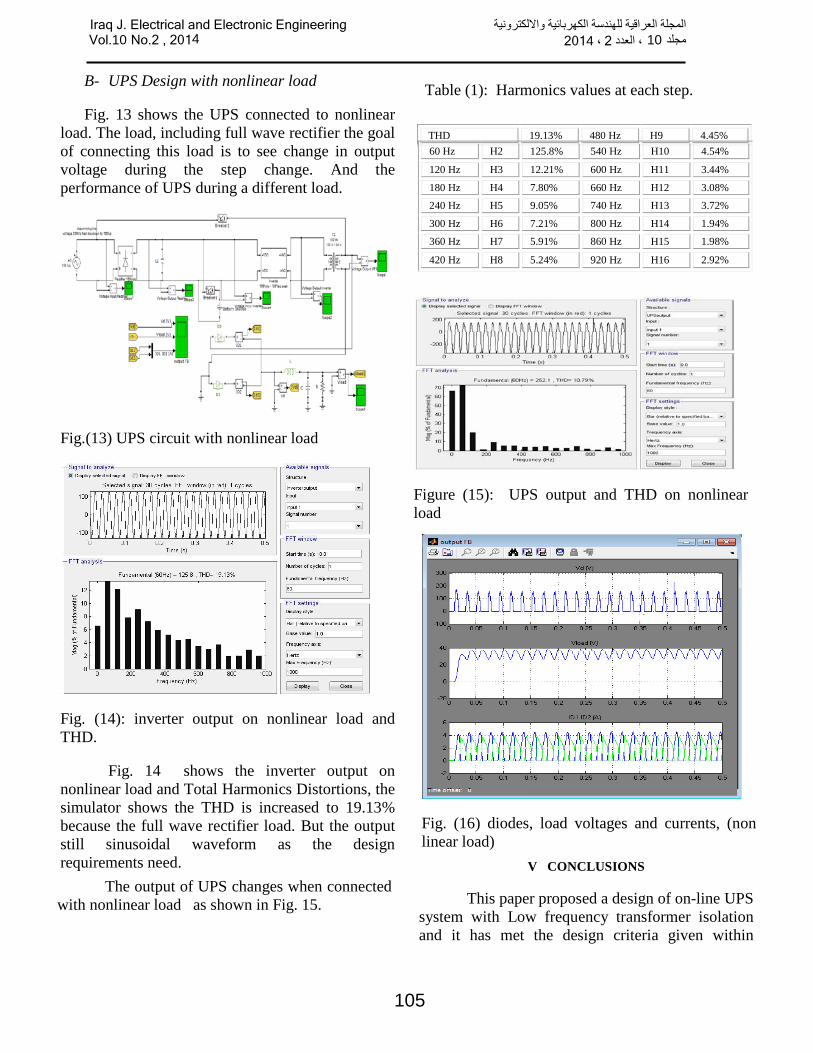
B- UPS Design with nonlinear load
Fig. 13 shows the UPS connected to nonlinear load. The load, including full wave rectifier the goal of connecting this load is to see change in output voltage during the step change. And the performance of UPS during a different load.
Fig.(13) UPS circuit with nonlinear load
Fig. (14): inverter output on nonlinear load and THD.
Fig. 14 shows the inverter output on nonlinear load and Total Harmonics Distortions, the simulator shows the THD is increased to 19.13% because the full wave rectifier load. But the output still sinusoidal waveform as the design requirements need.
Table (1): Harmonics values at each step. THD 19.13% 480 Hz H9 4.45% 60 Hz H2 125.8% 540 Hz H10 4.54%
120 Hz H3 12.21% 600 Hz H11 3.44%
180 Hz H4 7.80% 660 Hz H12 3.08%
240 Hz H5 9.05% 740 Hz H13 3.72%
300 Hz H6 7.21% 800 Hz H14 1.94%
360 Hz H7 5.91% 860 Hz H15 1.98%
420 Hz H8 5.24% 920 Hz H16 2.92%
Figure (15): UPS output and THD on nonlinear load
The output of UPS changes when connected
with nonlinear load as shown in Fig. 15.
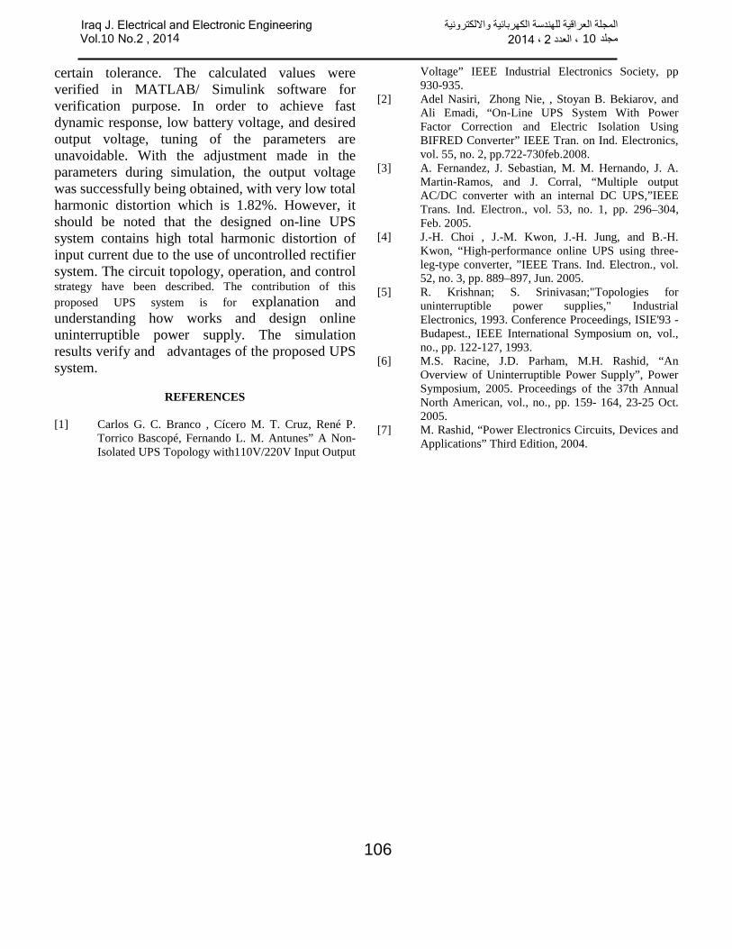
Fig. (16) diodes, load voltages and currents, (non linear load)
V CONCLUSIONS
This paper proposed a design of on-line UPS system with Low frequency transformer isolation and it has met the design criteria given within
Iraq J. Electrical and Electronic Engineeringالمجلة العراقية للهندسة الكهربائية وااللكترونية ، العدد 10مجلد 2 ، 2014 Vol.10 No.2 , 2014
105
certain tolerance. The calculated values were verified in MATLAB/ Simulink software for verification purpose. In order to achieve fast dynamic response, low battery voltage, and desired output voltage, tuning of the parameters are unavoidable. With the adjustment made in the parameters during simulation, the output voltage was successfully being obtained, with very low total harmonic distortion which is 1.82%. However, it should be noted that the designed on-line UPS system contains high total harmonic distortion of input current due to the use of uncontrolled rectifier system. The circuit topology, operation, and control strategy have been described. The contribution of this proposed UPS system is for explanation and understanding how works and design online uninterruptible power supply. The simulation results verify and advantages of the proposed UPS system.
REFERENCES [1] Carlos G. C. Branco , Cícero M. T. Cruz, René P.
Torrico Bascopé, Fernando L. M. Antunes” A Non-Isolated UPS Topology with110V/220V Input Output
Voltage” IEEE Industrial Electronics Society, pp 930-935.
[2] Adel Nasiri, Zhong Nie, , Stoyan B. Bekiarov, and Ali Emadi, “On-Line UPS System With Power Factor Correction and Electric Isolation Using BIFRED Converter” IEEE Tran. on Ind. Electronics, vol. 55, no. 2, pp.722-730feb.2008.
[3] A. Fernandez, J. Sebastian, M. M. Hernando, J. A. Martin-Ramos, and J. Corral, “Multiple output AC/DC converter with an internal DC UPS,”IEEE Trans. Ind. Electron., vol. 53, no. 1, pp. 296–304, Feb. 2005.
[4] J.-H. Choi , J.-M. Kwon, J.-H. Jung, and B.-H. Kwon, “High-performance online UPS using three- leg-type converter, ”IEEE Trans. Ind. Electron., vol. 52, no. 3, pp. 889–897, Jun. 2005.
[5] R. Krishnan; S. Srinivasan;"Topologies for uninterruptible power supplies," Industrial Electronics, 1993. Conference Proceedings, ISIE'93 - Budapest., IEEE International Symposium on, vol., no., pp. 122-127, 1993.
[6] M.S. Racine, J.D. Parham, M.H. Rashid, “An Overview of Uninterruptible Power Supply”, Power Symposium, 2005. Proceedings of the 37th Annual North American, vol., no., pp. 159- 164, 23-25 Oct. 2005.
[7] M. Rashid, “Power Electronics Circuits, Devices and Applications” Third Edition, 2004.
Iraq J. Electrical and Electronic Engineeringالمجلة العراقية للهندسة الكهربائية وااللكترونية ، العدد 10مجلد 2 ، 2014 Vol.10 No.2 , 2014
106