Embed Size (px)
Citation preview
Svensk Kärnbränslehantering ABSwedish Nuclear Fueland Waste Management CoBox 5864SE-102 40 Stockholm Sweden Tel 08-459 84 00 +46 8 459 84 00Fax 08-661 57 19 +46 8 661 57 19
P-07-55
Oskarshamn site investigation
Revision of borehole deviation measurements in Oskarshamn
Leif Stenberg, Nils Håkanson
Svensk Kärnbränslehantering AB
September 2007
CM
Gru
ppen
AB
, Bro
mm
a, 2
007
Tänd ett lager:
P, R eller TR.
Oskarshamn site investigation
Revision of borehole deviation measurements in Oskarshamn
Leif Stenberg, Nils Håkanson
Svensk Kärnbränslehantering AB
September 2007
ISSN 1651-4416
SKB P-07-55
Keywords: Borehole deviation, Bearing, Inclination, Uncertainty, Flexit, Maxibor, Acoustic Televiewer, Boremac.
Data in SKB’s database can be changed for different reasons. Minor changes in SKB’s database will not necessarily result in a revised report. Data revisions may also be presented as supplements, available at www.skb.se.
A pdf version of this document can be downloaded from www.skb.se.
3
Abstract
Within the scope of SKB’s site investigations, accurate borehole deviation measure ments are crucial for allotting data from different surveys of borehole logging correct positions in space. Because full-scale calibration of the deviation logging equipment is normally not possible, the only available measure of quality is repeat ability, i.e. a comparison of several deviation loggings in the same borehole.
In connection with a major quality revision (autumn 2006 to early spring 2007) regarding orien-tation of geological objects (fractures, rock contacts etc) a reassessment of the relia bility of deviation measurements was made. Some problems with low repeat ability and some problems with correct length measurements when using the standard method for deviation measurements caused a decision to introduce a new strategy. This new strategy implies the possibility to combine several deviation measurements.
Another important result of the revision is the introduction of an uncertainty of a devia tion mea surement. The uncertainty is presented both as uncertainties of inclina tion and bearing, and in geometrical terms as an “uncertainty cone” around each borehole.
This document reports the results gained by the revision of the borehole deviation measure ments in Oskarshamn.
4
Sammanfattning
I SKB:s platsundersökningar är noggranna krökningsmätningar av borrhål avgörande för en geometrisk korrekt placering av resultaten från olika borrhålsundersökningar. Efter som en instrumentkontroll i full skala inte har varit möjlig, återstår en jämförelse av upp repade mätningar i samma borrhål som det enda kvalitetsmåttet.
I samband med en revision (hösten 2006 och våren 2007) kring orienteringen av geolo giska objekt (sprickor, bergkontakter m m), omvärderades tillförlitligheten av kröknings mätningarna. Den hittills använda standardmetoden för krökningsmätningar visade sig ha problem med låg repeterbarhet och problem med längdmätningen. Detta föranledde introduktionen av en ny strategi, som möjliggör en kombination av flera oberoende krökningsmätningar.
Ett annat viktigt resultat av revisionen är introduktionen av ett mått på onoggrannheten av krökningsmätningar. Onoggrannheten presenteras som en individuell onoggrannhet av inklina-tion och bäring, men också i geometriska termer som en konisk ”strut” kring borrhålsaxeln.
I denna rapport presenteras resultatet av revisionen av krökningsmätningar utförda inom Platsundersökning Oskarshamn.
5
Contents
1 Introduction 71.1 Nomenclature 8
2 Objective and scope 9
3 Equipment 113.1 Description of equipment/interpretation tools 11
3.1.1 Description and principles of magnetometer/accelerometer based tools 11
3.1.2 Description and principles of the optical tool 113.1.3 Description and principles of the Acoustic Televiewer 123.1.4 Description and principles of Boremac 12
4 Execution 134.1 Preparations 134.2 Execution of field work 13
4.2.1 Logging with Flexit Smart Tool 134.2.2 Logging with Maxibor 134.2.3 Logging with Acoustic Televiewer 154.2.4 Logging with Boremac 15
4.3 Data handling/post processing of measured data 154.3.1 Magnetometer/accelerometer methods 154.3.2 Optical method 174.3.3 Acoustic Televiewer 174.3.4 Boremac 184.3.5 Boreholes without deviation measurements 18
4.4 Borehole deviations 184.4.1 “Initial” procedure (before revision) for calculation
of borehole deviation 184.4.2 New procedure (after revision) for calculation
of borehole deviation 194.4.3 Estimation of uncertainties in borehole deviation loggings 20
5 Results 25
Appendices attached on CD 29Appendix A. Details of the core-drilled boreholesAppendix B. Details of the percussion-drilled boreholes
7
1 Introduction
Within the scope of SKB’s site investigations accurate borehole deviation measurements are crucial for allotting data from different surveys of borehole logging correct positions in space.
Full-scale calibration of the deviation logging equipment has not been possible, except for some minor verification tests in a short borehole located on Äspö (KAS13), extending from the ground surface to 256 m borehole length where the break through was located in the Äspö-tunnel. As a result of this fact, the only available measure of quality is repeat ability, i.e. a comparison of several deviation loggings in the same borehole.
Within the site investigation project (from 2002 to 2007) two types of instrumentation for borehole deviation measurements have routinely been applied:
• Opticaltool
• Magnetometer/accelerometerbasedtools
In most core-drilled boreholes in Oskarshamn both methods have been applied. Further more, repeated measure ments with both types of instruments have been performed in many of the boreholes. In a few core-drilled boreholes and some percussion-drilled boreholes deviation data from other equipment (e.g. Acoustic Televiewer) has been used.
Regarding core-drilled boreholes, two boreholes were measured with one Boremac logging (executed 1988 and 1993 respectively), one borehole was measured with one Optical tool logging (Maxibor), 20 boreholes (borehole length less than 200 m) were measured with two magnetometer/accelerometer loggings and 16 boreholes were measured with one or two loggings with both methods.
Regarding percussion-drilled boreholes in Oskarshamn 13 boreholes were measured with one magnetometer/accelerometer-logging (Flexit), 15 boreholes were measured with Acoustic or Optical Televiewer. Nine percussion-drilled boreholes, which were drilled in 1987, were measured with an inclinometer/magnetometer (compass) based method (Boremac). Six boreholes were not measured at all, only the starting direction (inclination and bearing) was measured.
Initially, the deviation measurements based upon the optical tool were used for calcula ting the resulting deviation files for the core-drilled boreholes. In connection with a major quality revision (autumn 2006 to early spring 2007) regarding orientation of geological objects (fractures, rock contacts etc) a reassessment of the reliability of deviation measurements was made. Some problems with low repeat ability and some problems with length measurements when using the optical tool, caused a decision to introduce a new strategy. This new strategy implies the possibility to combine several deviation measurements and gives a quantification of the uncertainty.
This document reports the results gained by the revision of the borehole deviation measure ments in Oskarshamn.
As a result of the revision, a new strategy is applied in Sicada for handling borehole deviation data: several deviation logging activities can now be combined through a “running median algorithm” to define new deviation data. The recipe for combining different logging files is given in an “EG154-file”, which des cribes which bore hole length intervals from different deviation loggings that should be included in the calcu lation.
Another important result of the revision is the introduction of an uncertainty of mea surement. All deviation loggings which are not ERROR-marked are used to calculate the differences from the new calculated deviation file. This implies that the uncertainty calculation may be based on
8
more deviation loggings than those specified in the “EG154”-file. The 90th percen tile value of these diffe ren ces is used as a measure of the uncertainties of inclina tion and bearing.
The new deviation calculations, based upon this revision, are all stored in Sicada, and they are traceable by the borehole ID codes.
Original data from the reported activity are stored in the primary database Sicada, where they are traceable by the borehole ID codes. Only data in SKB’s databases are accepted for further inter-pretation and modelling. The data presented in this report are regarded as copies of the original data. Data in the databases may be revised, if needed. Such revisions will not necessarily result in a revision of the P-report, although the normal procedure is that major data revisions entail a revision of the P-report. Minor data revisions are normally presented as supplements, available at www.skb.se.
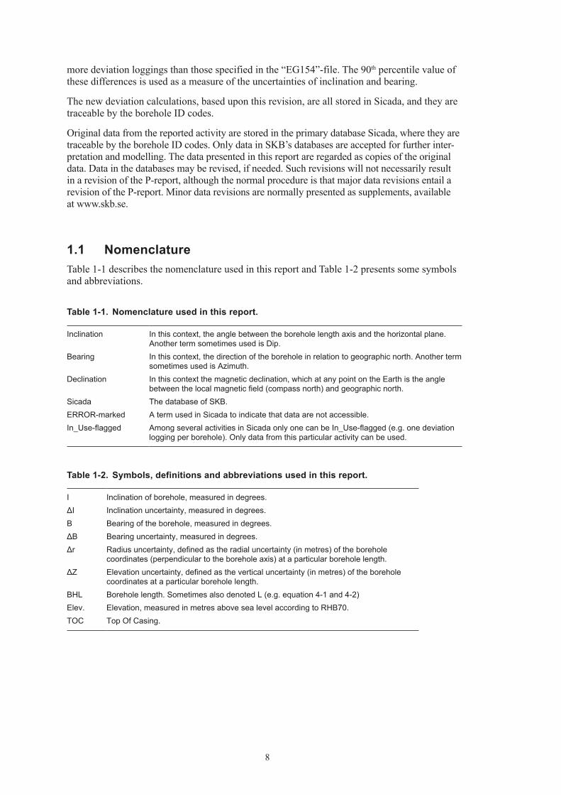
1.1 NomenclatureTable 1-1 describes the nomenclature used in this report and Table 1-2 presents some symbols and abbreviations.
Table 1‑1. Nomenclature used in this report.
Inclination In this context, the angle between the borehole length axis and the horizontal plane. Another term sometimes used is Dip.
Bearing In this context, the direction of the borehole in relation to geographic north. Another term sometimes used is Azimuth.
Declination In this context the magnetic declination, which at any point on the Earth is the angle between the local magnetic field (compass north) and geographic north.
Sicada The database of SKB.ERROR-marked A term used in Sicada to indicate that data are not accessible.In_Use-flagged Among several activities in Sicada only one can be In_Use-flagged (e.g. one deviation
logging per borehole). Only data from this particular activity can be used.
Table 1‑2. Symbols, definitions and abbreviations used in this report.
I Inclination of borehole, measured in degrees.ΔI Inclination uncertainty, measured in degrees.B Bearing of the borehole, measured in degrees.ΔB Bearing uncertainty, measured in degrees.Δr Radius uncertainty, defined as the radial uncertainty (in metres) of the borehole
coordinates (perpendicular to the borehole axis) at a particular borehole length.ΔZ Elevation uncertainty, defined as the vertical uncertainty (in metres) of the borehole
coordinates at a particular borehole length.BHL Borehole length. Sometimes also denoted L (e.g. equation 4-1 and 4-2)Elev. Elevation, measured in metres above sea level according to RHB70.TOC Top Of Casing.
9
2 Objective and scope
The objective with deviation measurements is to calculate the deviation of a borehole as a function of borehole length to achive geometrical data of the borehole, e.g. X-, Y-, and Z-coordinates for points with a predetermined interval along the borehole. As it is only possible to assign coordinates only to a limited number of points the intermediate borehole sections are interpolated between the coordinates of the points and extrapolated to the end of the borehole from the last point assigned coordinates.
Accurate deviation measurements are crucial for the interpretation of other borehole investigations. In an internal PM (SKB ID 1063373), sources of errors were identified, and it was recommended to access an estimate of uncertainties as well. As a result, a review of all borehole deviation measurements was initiated.
This report describes the outcome of the revision.
11
3 Equipment
3.1 Description of equipment/interpretation tools
3.1.1 Description and principles of magnetometer/accelerometer based tools
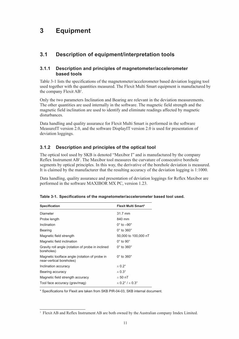
Table 3-1 lists the specifications of the magnetometer/accelerometer based deviation logging tool used together with the quantities measured. The Flexit Multi Smart equipment is manufac tured by the company Flexit AB1.
Only the two parameters Inclination and Bearing are relevant in the deviation measure ments. The other quantities are used internally in the software. The magnetic field strength and the magnetic field inclination are used to identify and eliminate readings affected by magnetic disturbances.
Data handling and quality assurance for Flexit Multi Smart is performed in the software MeasureIT version 2.0, and the software DisplayIT version 2.0 is used for presentation of deviation loggings.
3.1.2 Description and principles of the optical toolThe optical tool used by SKB is denoted “Maxibor I” and is manufactured by the company Reflex Instrument AB1. The Maxibor tool measures the curvature of conse cutive borehole segments by optical principles. In this way, the derivative of the borehole deviation is measured. It is claimed by the manufacturer that the resulting accuracy of the deviation logging is 1:1000.
Data handling, quality assurance and presentation of deviation loggings for Reflex Maxibor are performed in the software MAXIBOR MX PC, version 1.23.
1 Flexit AB and Reflex Instrument AB are both owned by the Australian company Imdex Limited.
Table 3‑1. Specifications of the magnetometer/accelerometer based tool used.
Specification Flexit Multi Smart*
Diameter 31.7 mmProbe length 840 mmInclination 0° to –90°Bearing 0° to 360°Magnetic field strength 50,000 to 100,000 nTMagnetic field inclination 0° to 90°Gravity roll angle (rotation of probe in inclined boreholes)
0° to 360°
Magnetic toolface angle (rotation of probe in near-vertical boreholes)
0° to 360°
Inclination accuracy ± 0.2°Bearing accuracy ± 0.3°Magnetic field strength accuracy ± 50 nTTool face accuracy (grav/mag) ± 0.2° / ± 0.3°
* Specifications for Flexit are taken from SKB PIR-04-03, SKB internal document.
12
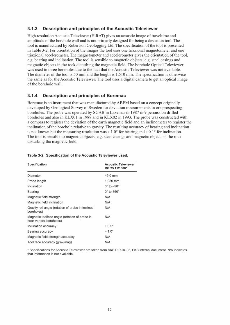
3.1.3 Description and principles of the Acoustic TeleviewerHigh resolution Acoustic Televiewer (HiRAT) gives an acoustic image of traveltime and amplitude of the borehole wall and is not primarly designed for being a deviation tool. The tool is manufactured by Robertson Geologging Ltd. The specification of the tool is presented in Table 3-2. For orientation of the images the tool uses one triaxional magnetometer and one triaxional accelerometer. The magnetometer and accelerometer gives the orientation of the tool, e.g. bearing and inclination. The tool is sensible to magnetic objects, e.g. steel casings and magnetic objects in the rock disturbing the magnetic field. The borehole Optical Televiewer was used in three boreholes due to the fact that the Acoustic Televiewer was not available. The diameter of the tool is 50 mm and the length is 1,510 mm. The specification is otherwise the same as for the Acoustic Televiewer. The tool uses a digital camera to get an optical image of the borehole wall.
3.1.4 Description and principles of BoremacBoremac is an instrument that was manufactured by ABEM based on a concept originally developed by Geological Survey of Sweden for deviation measurements in ore prospecting boreholes. The probe was operated by SGAB in Laxemar in 1987 in 9 percussion drilled boreholes and also in KLX01 in 1988 and in KLX02 in 1993. The probe was constructed with a compass to register the deviation of the earth magnetic field and an inclinometer to register the inclination of the borehole relative to gravity. The resulting accuracy of bearing and inclination is not known but the measuring resolution was ± 1.0° for bearing and ± 0.1° for inclination. The tool is sensible to magnetic objects, e.g. steel casings and magnetic objects in the rock disturbing the magnetic field.
Table 3‑2. Specification of the Acoustic Televiewer used.
Specification Acoustic Televiewer RG 25 112 000*
Diameter 45.0 mmProbe length 1,980 mmInclination 0° to –90°Bearing 0° to 360°Magnetic field strength N/AMagnetic field inclination N/AGravity roll angle (rotation of probe in inclined boreholes)
N/A
Magnetic toolface angle (rotation of probe in near-vertical boreholes)
N/A
Inclination accuracy ± 0.5°Bearing accuracy ± 1.0°Magnetic field strength accuracy N/ATool face accuracy (grav/mag) N/A
* Specifications for Acoustic Televiewer are taken from SKB PIR-04-03, SKB internal document. N/A indicates that information is not available.
13
4 Execution
4.1 PreparationsBefore performing deviation logging, the TOC (Top Of Casing) of the borehole needs to be surveyed for the coordinates (Northing, Easting and Elevation) in RT90/RHB70. The coordinates are used in calculating the borehole deviation.
Furthermore, before performing Maxibor measurements, the inclination and bearing at TOC and at 3 m BHL need to be determined. These are used as starting values in the Maxibor survey.
4.2 Execution of field workIn general, two deviation loggings are performed with 3 m point interval, one in downward and one in upward direction. Furthermore, as a general principle in core-drilled boreholes, at least two independent measurement methods were applied to allow for quality checking.
In accordance with the method description SKB MD 224.001 version 1.02, the optical method (Maxibor) should be used for deviation logging of core-drilled boreholes, and a magnetic/accelerometer method (Flexit or Reflex) in percussion-drilled holes. Until December 2006, this was the procedure applied at the site investigations at Forsmark and Simpevarp/Laxemar in Oskarshamn.
4.2.1 Logging with Flexit Smart Tool
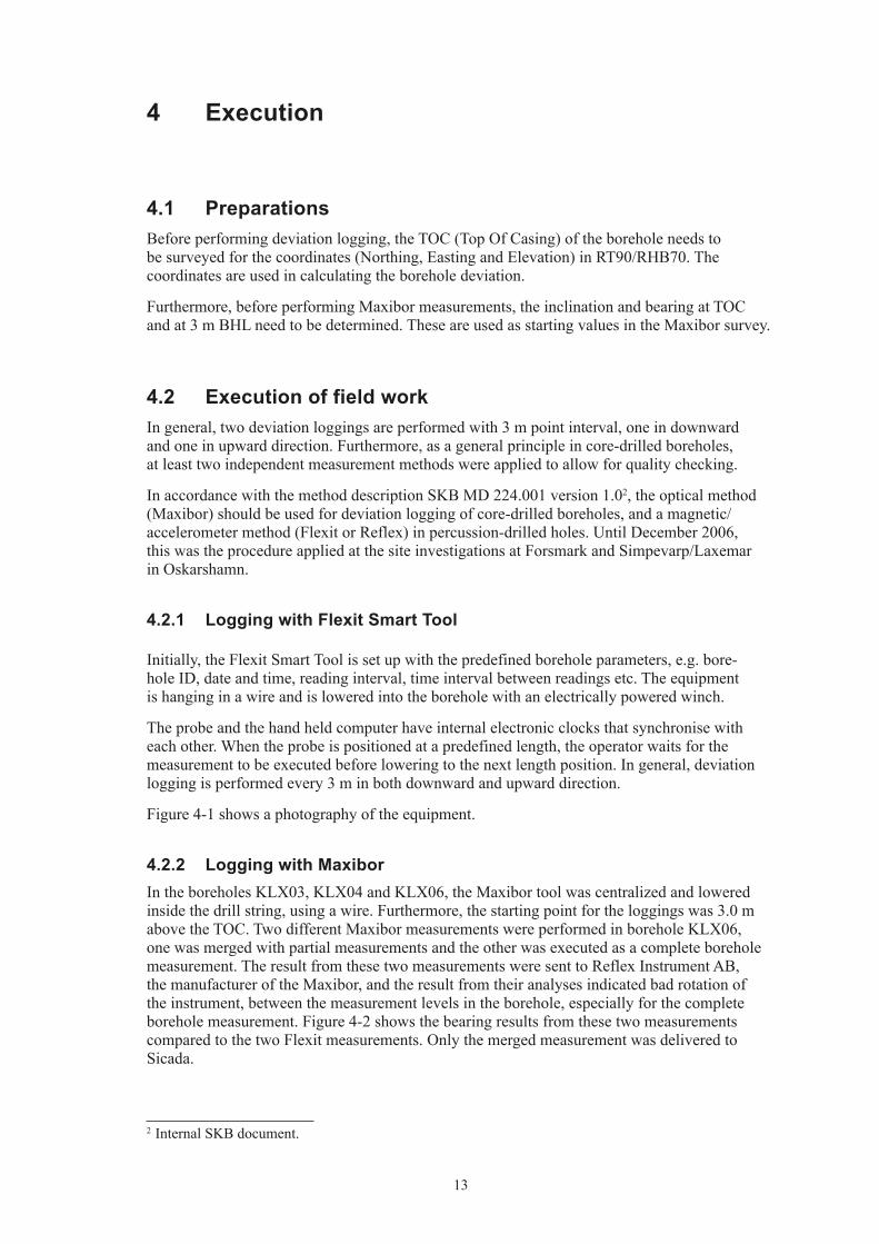
Initially, the Flexit Smart Tool is set up with the predefined borehole parameters, e.g. bore-hole ID, date and time, reading interval, time interval between readings etc. The equipment is hanging in a wire and is lowered into the borehole with an electrically powered winch.
The probe and the hand held computer have internal electronic clocks that synchronise with each other. When the probe is positioned at a predefined length, the operator waits for the measurement to be executed before lowering to the next length position. In general, deviation logging is performed every 3 m in both downward and upward direction.
Figure 4-1 shows a photography of the equipment.
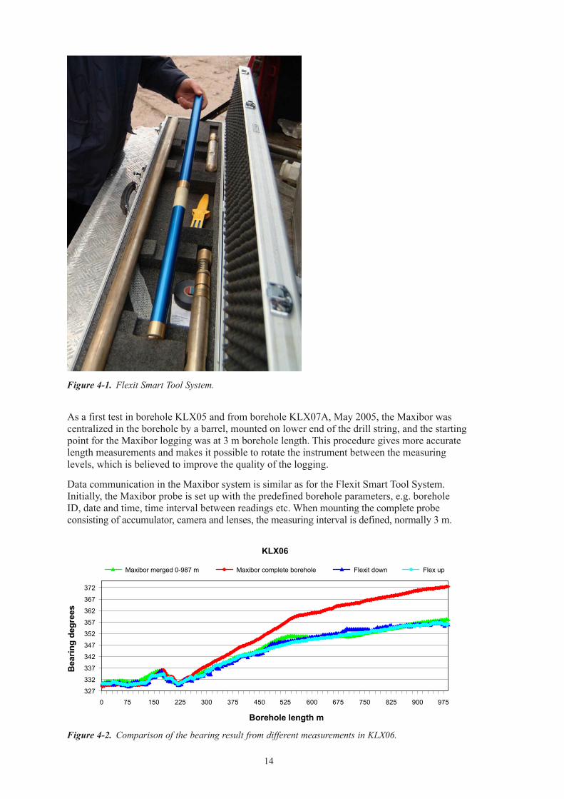
4.2.2 Logging with MaxiborIn the boreholes KLX03, KLX04 and KLX06, the Maxibor tool was centralized and lowered inside the drill string, using a wire. Furthermore, the star ting point for the loggings was 3.0 m above the TOC. Two different Maxibor measurements were performed in borehole KLX06, one was merged with partial measurements and the other was executed as a complete borehole measurement. The result from these two measurements were sent to Reflex Instrument AB, the manufacturer of the Maxibor, and the result from their analyses indicated bad rotation of the instrument, between the measurement levels in the borehole, especially for the complete borehole measurement. Figure 4-2 shows the bearing results from these two measurements compared to the two Flexit measurements. Only the merged measurement was delivered to Sicada.
2 Internal SKB document.
14
Figure 4‑1. Flexit Smart Tool System.
Figure 4‑2. Comparison of the bearing result from different measurements in KLX06.
KLX06
327
332
337
342
347
352
357
362
367
372
0 75 150 225 300 375 450 525 600 675 750 825 900 975
Borehole length m
Bea
ring
degr
ees
Maxibor merged 0-987 m Maxibor complete borehole Flexit down Flex up
As a first test in borehole KLX05 and from borehole KLX07A, May 2005, the Maxibor was centra lized in the borehole by a barrel, mounted on lower end of the drill string, and the star ting point for the Maxibor logging was at 3 m borehole length. This procedure gives more accurate length measurements and makes it possible to rotate the instrument between the measuring levels, which is believed to improve the quality of the logging.
Data communication in the Maxibor system is similar as for the Flexit Smart Tool System. Initially, the Maxibor probe is set up with the predefined borehole parameters, e.g. borehole ID, date and time, time interval between readings etc. When mounting the complete probe consisting of accumulator, camera and lenses, the measuring interval is defined, normally 3 m.
15
The Maxibor probe and the computer have internal electronic clocks that synchronise with each other, and when the probe is positioned at a predefined length, the operator is waiting for the measurement to be executed before lowering to the next 3 m station. In general, deviation logging is performed every 3 m in both downward and upward direction.
4.2.3 Logging with Acoustic TeleviewerThe Acoustic Televiewer is set up with the predefined borehole parameters, e.g. borehole ID and date and time. The equipment is hanging in a wire and is lowered into the borehole with an electrically powered winch. The logging is performed continiously in upward direction. Readings are taken every 0.1 m. The logging velocity is 2 m/min for high resolution in the images but the tool has normally been operated with 10 m/min in order to locate length marks every 50 metres in the borehole mainly for length adjustment and cross-correlation of natural gamma with other tools.
4.2.4 Logging with BoremacThe logging with Boremac is similar to logging with the Flexit tool but the readings, e.g. length, deviation and inclination was manually written on a protocol. The equipment was hanging in a wire and was lowered into the borehole with an electrically powered winch. In the percussion drilled boreholes the winch was manually operated. In the 9 percussion-drilled boreholes the deviation logging was performed every 1 m from TOC down to 50 m and then every 10th m down to the bottom of the borehole. The core-drilled borehole KLX01 was logged every 10th m from TOC to 690 m and KLX02 was logged every 10th or 20th m from TOC to 1,443 m respectively.
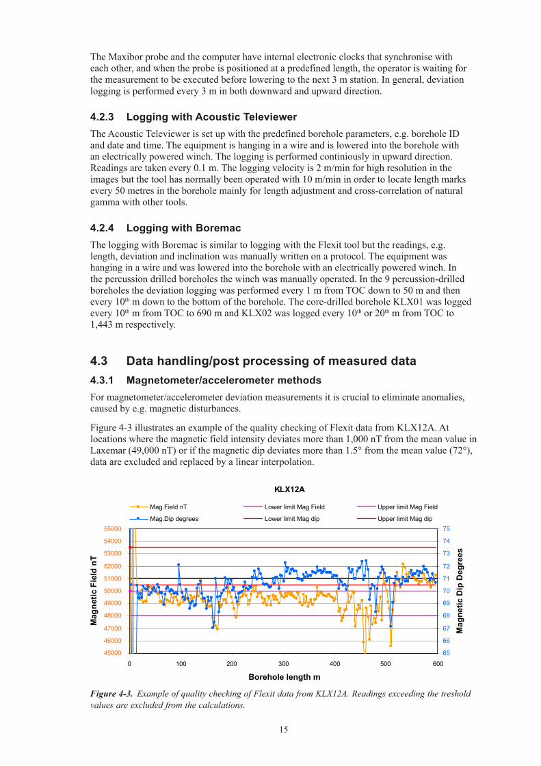
4.3 Data handling/post processing of measured data4.3.1 Magnetometer/accelerometer methodsFor magnetometer/accelerometer deviation measurements it is crucial to eliminate anomalies, caused by e.g. magnetic disturbances.
Figure 4-3 illustrates an example of the quality checking of Flexit data from KLX12A. At locations where the magnetic field intensity deviates more than 1,000 nT from the mean value in Laxemar (49,000 nT) or if the magne tic dip deviates more than 1.5° from the mean value (72°), data are excluded and replaced by a linear interpolation.
Figure 4‑3. Example of quality checking of Flexit data from KLX12A. Readings exceeding the treshold values are excluded from the calculations.
KLX12A
45000
46000
47000
48000
49000
50000
51000
52000
53000
54000
55000
0 100 200 300 400 500 600
Borehole length m
Mag
netic
Fie
ld n
T
65
66
67
68
69
70
71
72
73
74
75
Mag
netic
Dip
Deg
rees
Mag.Field nT Lower limit Mag Field Upper limit Mag Field
Mag.Dip degrees Lower limit Mag dip Upper limit Mag dip
16
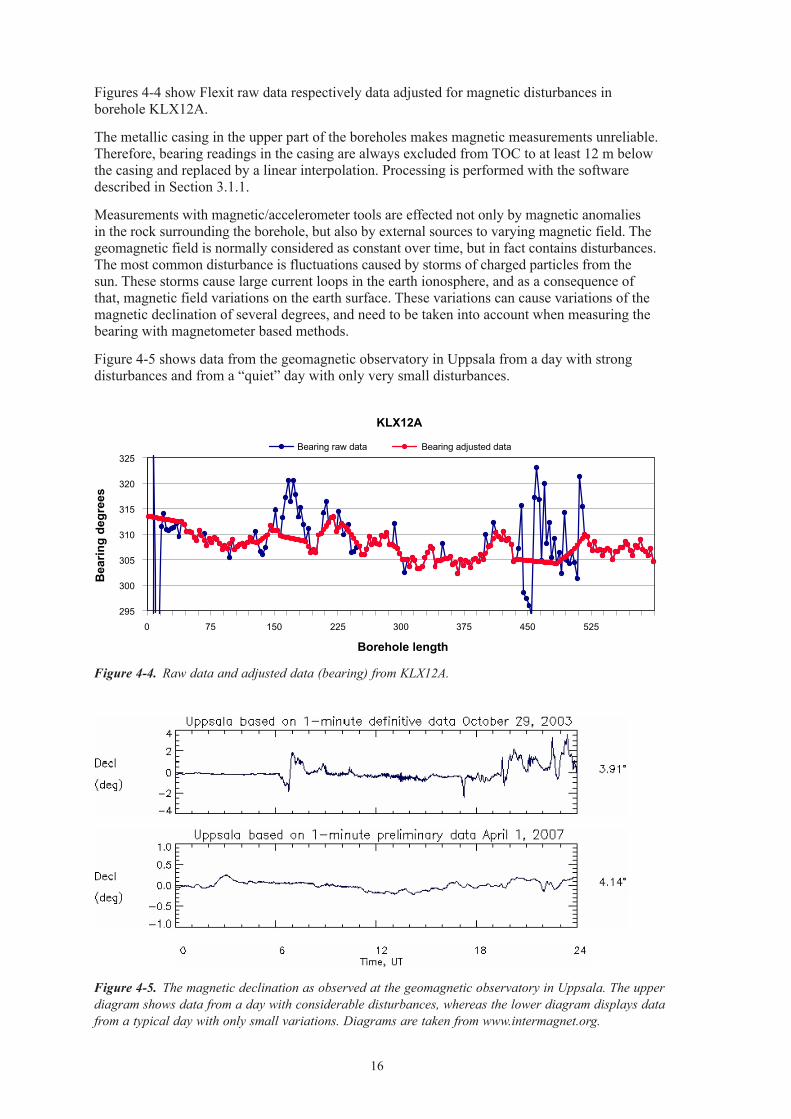
Figures 4-4 show Flexit raw data respectively data adjusted for magnetic disturbances in borehole KLX12A.
The metallic casing in the upper part of the boreholes makes magnetic measurements unreliable. Therefore, bearing readings in the casing are always excluded from TOC to at least 12 m below the casing and replaced by a linear interpolation. Processing is performed with the software described in Section 3.1.1.
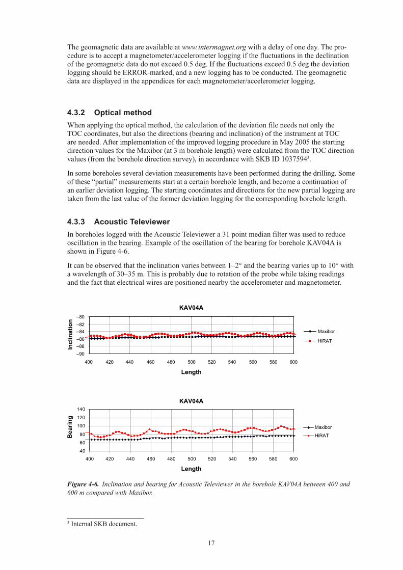
Measurements with magnetic/accelerometer tools are effected not only by magnetic anomalies in the rock surrounding the borehole, but also by external sources to varying magnetic field. The geomagnetic field is normally considered as constant over time, but in fact contains disturbances. The most common disturbance is fluctuations caused by storms of charged particles from the sun. These storms cause large current loops in the earth ionosphere, and as a consequence of that, magnetic field variations on the earth surface. These variations can cause variations of the magnetic declination of several degrees, and need to be taken into account when measuring the bearing with magnetometer based methods.
Figure 4-5 shows data from the geomagnetic observatory in Uppsala from a day with strong disturbances and from a “quiet” day with only very small disturbances.
Figure 4‑4. Raw data and adjusted data (bearing) from KLX12A.
Figure 4‑5. The magnetic declination as observed at the geomagnetic observatory in Uppsala. The upper diagram shows data from a day with considerable disturbances, whereas the lower diagram displays data from a typical day with only small variations. Diagrams are taken from www.intermagnet.org.
KLX12A
295
300
305
310
315
320
325
0 75 150 225 300 375 450 525
Borehole length
Bea
ring
degr
ees
Bearing raw data Bearing adjusted data
17
The geomagnetic data are available at www.intermagnet.org with a delay of one day. The pro-cedure is to accept a magnetometer/accelerometer logging if the fluctuations in the declination of the geomagnetic data do not exceed 0.5 deg. If the fluctuations exceed 0.5 deg the deviation logging should be ERROR-marked, and a new logging has to be conducted. The geomagnetic data are displayed in the appendices for each mag neto meter/accelerometer logging.
4.3.2 Optical methodWhen applying the optical method, the calculation of the deviation file needs not only the TOC coordinates, but also the direc tions (bearing and inclination) of the instrument at TOC are needed. After implementation of the improved logging procedure in May 2005 the starting direction values for the Maxibor (at 3 m borehole length) were calculated from the TOC direction values (from the borehole direction survey), in accordance with SKB ID 10375943.
In some boreholes several deviation measurements have been performed during the drilling. Some of these “partial” measure ments start at a certain borehole length, and become a continuation of an earlier deviation logging. The starting coordinates and directions for the new partial logging are taken from the last value of the former deviation logging for the corresponding borehole length.
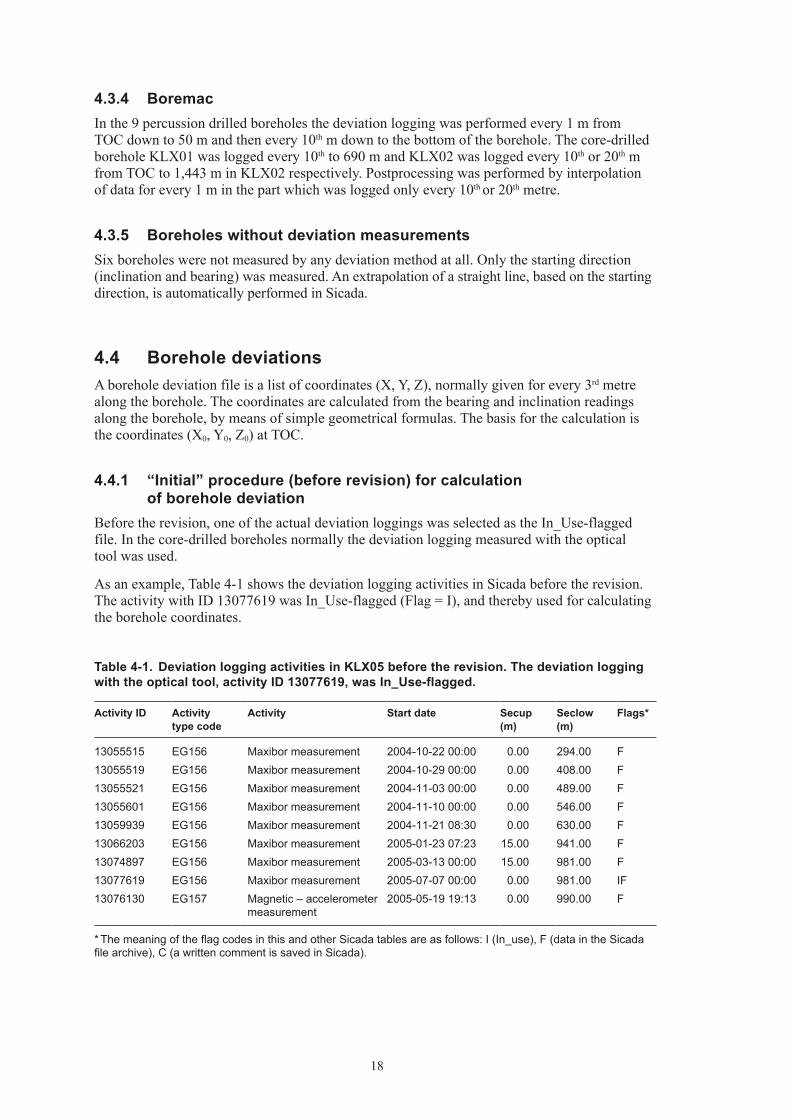
4.3.3 Acoustic TeleviewerIn boreholes logged with the Acoustic Televiewer a 31 point median filter was used to reduce oscillation in the bearing. Example of the oscillation of the bearing for borehole KAV04A is shown in Figure 4-6.
It can be observed that the inclination varies between 1–2° and the bearing varies up to 10° with a wavelength of 30–35 m. This is probably due to rotation of the probe while taking readings and the fact that electrical wires are positioned nearby the accelerometer and magnetometer.
3 Internal SKB document.
Figure 4‑6. Inclination and bearing for Acoustic Televiewer in the borehole KAV04A between 400 and 600 m compared with Maxibor.
KAV04A
–90–88–86–84–82–80
400 420 440 460 480 500 520 540 560 580 600
Length
Incl
inat
ion
Maxibor
HiRAT
KAV04A
40
60
80
100
120
140
400 420 440 460 480 500 520 540 560 580 600
Length
Bea
ring
Maxibor
HiRAT
18
4.3.4 BoremacIn the 9 percussion drilled boreholes the deviation logging was performed every 1 m from TOC down to 50 m and then every 10th m down to the bottom of the borehole. The core-drilled borehole KLX01 was logged every 10th to 690 m and KLX02 was logged every 10th or 20th m from TOC to 1,443 m in KLX02 respectively. Postprocessing was performed by interpolation of data for every 1 m in the part which was logged only every 10th or 20th metre.
4.3.5 Boreholes without deviation measurementsSix boreholes were not measured by any deviation method at all. Only the starting direction (inclination and bearing) was measured. An extrapolation of a straight line, based on the starting direction, is automatically performed in Sicada.
4.4 Borehole deviationsA borehole deviation file is a list of coordinates (X, Y, Z), normally given for every 3rd metre along the borehole. The coordinates are calculated from the bearing and inclination readings along the borehole, by means of simple geometrical formulas. The basis for the calculation is the coordinates (X0, Y0, Z0) at TOC.
4.4.1 “Initial” procedure (before revision) for calculation of borehole deviation
Before the revision, one of the actual deviation loggings was selected as the In_Use-flagged file. In the core-drilled boreholes normally the deviation logging measured with the optical tool was used.
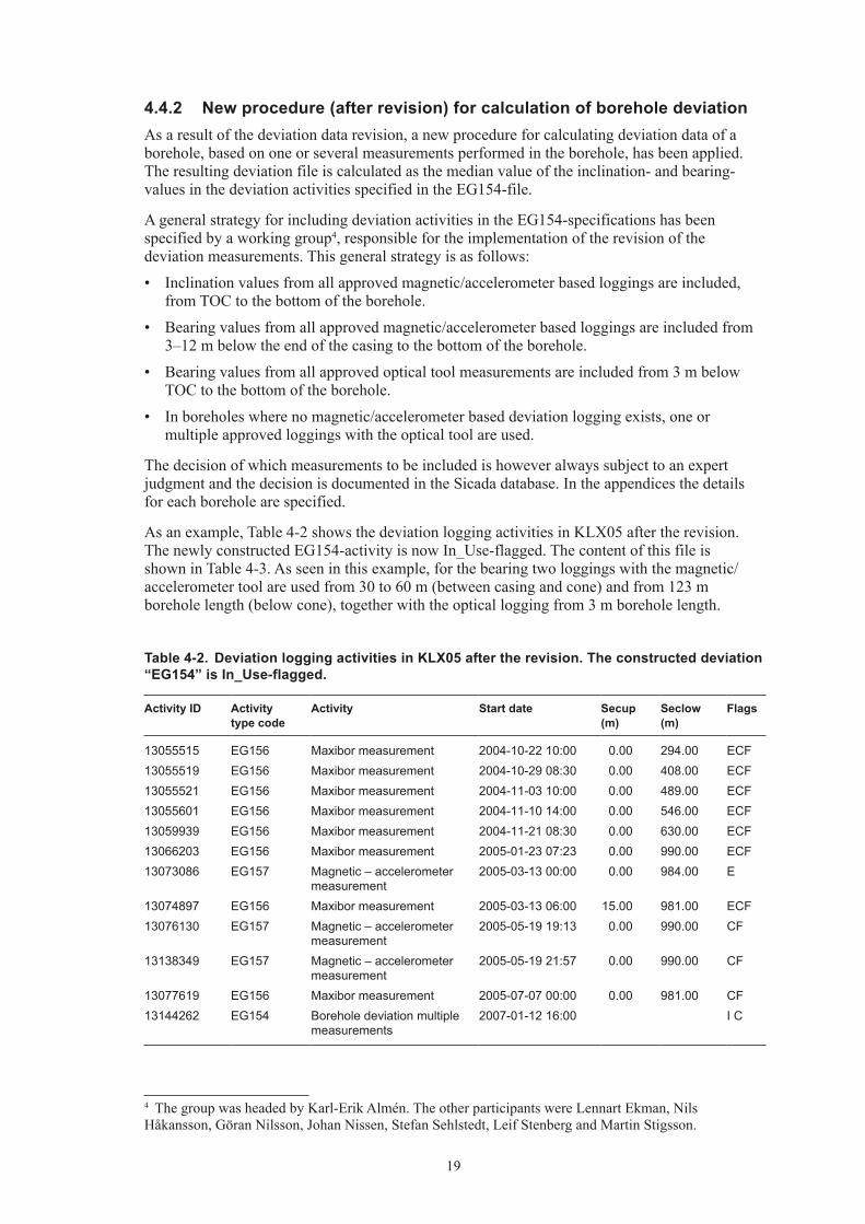
As an example, Table 4-1 shows the deviation logging activities in Sicada before the revision. The activity with ID 13077619 was In_Use-flagged (Flag = I), and thereby used for calculating the borehole coordinates.
Table 4‑1. Deviation logging activities in KLX05 before the revision. The deviation logging with the optical tool, activity ID 13077619, was In_Use‑flagged.
Activity ID Activity type code
Activity Start date Secup (m)
Seclow (m)
Flags*
13055515 EG156 Maxibor measurement 2004-10-22 00:00 0.00 294.00 F13055519 EG156 Maxibor measurement 2004-10-29 00:00 0.00 408.00 F13055521 EG156 Maxibor measurement 2004-11-03 00:00 0.00 489.00 F13055601 EG156 Maxibor measurement 2004-11-10 00:00 0.00 546.00 F13059939 EG156 Maxibor measurement 2004-11-21 08:30 0.00 630.00 F13066203 EG156 Maxibor measurement 2005-01-23 07:23 15.00 941.00 F13074897 EG156 Maxibor measurement 2005-03-13 00:00 15.00 981.00 F13077619 EG156 Maxibor measurement 2005-07-07 00:00 0.00 981.00 IF13076130 EG157 Magnetic – accelerometer
measurement2005-05-19 19:13 0.00 990.00 F
* The meaning of the flag codes in this and other Sicada tables are as follows: I (In_use), F (data in the Sicada file archive), C (a written comment is saved in Sicada).
19
4.4.2 New procedure (after revision) for calculation of borehole deviationAs a result of the deviation data revision, a new procedure for calculating deviation data of a borehole, based on one or several measurements performed in the borehole, has been applied. The resulting deviation file is calculated as the median value of the inclination- and bearing-values in the deviation activities specified in the EG154-file.
A general strategy for including deviation activities in the EG154-specifications has been specified by a working group4, responsible for the implementation of the revision of the deviation measurements. This general strategy is as follows:
• Inclinationvaluesfromallapprovedmagnetic/accelerometerbasedloggingsareincluded,from TOC to the bottom of the borehole.
• Bearingvaluesfromallapprovedmagnetic/accelerometerbasedloggingsareincludedfrom3–12 m below the end of the casing to the bottom of the borehole.
• Bearingvaluesfromallapprovedopticaltoolmeasurementsareincludedfrom3mbelowTOC to the bottom of the borehole.
• Inboreholeswherenomagnetic/accelerometerbaseddeviationloggingexists,oneormultiple approved loggings with the optical tool are used.
The decision of which measurements to be included is however always subject to an expert judgment and the decision is documented in the Sicada database. In the appendices the details for each borehole are specified.
As an example, Table 4-2 shows the deviation logging activities in KLX05 after the revision. The newly constructed EG154-activity is now In_Use-flagged. The content of this file is shown in Table 4-3. As seen in this example, for the bearing two loggings with the magnetic/accelerometer tool are used from 30 to 60 m (between casing and cone) and from 123 m borehole length (below cone), together with the optical logging from 3 m borehole length.
4 The group was headed by Karl-Erik Almén. The other participants were Lennart Ekman, Nils Håkansson, Göran Nilsson, Johan Nissen, Stefan Sehlstedt, Leif Stenberg and Martin Stigsson.
Table 4‑2. Deviation logging activities in KLX05 after the revision. The constructed deviation “EG154” is In_Use‑flagged.
Activity ID Activity type code
Activity Start date Secup (m)
Seclow (m)
Flags
13055515 EG156 Maxibor measurement 2004-10-22 10:00 0.00 294.00 ECF13055519 EG156 Maxibor measurement 2004-10-29 08:30 0.00 408.00 ECF13055521 EG156 Maxibor measurement 2004-11-03 10:00 0.00 489.00 ECF13055601 EG156 Maxibor measurement 2004-11-10 14:00 0.00 546.00 ECF13059939 EG156 Maxibor measurement 2004-11-21 08:30 0.00 630.00 ECF13066203 EG156 Maxibor measurement 2005-01-23 07:23 0.00 990.00 ECF13073086 EG157 Magnetic – accelerometer
measurement2005-03-13 00:00 0.00 984.00 E
13074897 EG156 Maxibor measurement 2005-03-13 06:00 15.00 981.00 ECF13076130 EG157 Magnetic – accelerometer
measurement2005-05-19 19:13 0.00 990.00 CF
13138349 EG157 Magnetic – accelerometer measurement
2005-05-19 21:57 0.00 990.00 CF
13077619 EG156 Maxibor measurement 2005-07-07 00:00 0.00 981.00 CF13144262 EG154 Borehole deviation multiple
measurements2007-01-12 16:00 I C
20
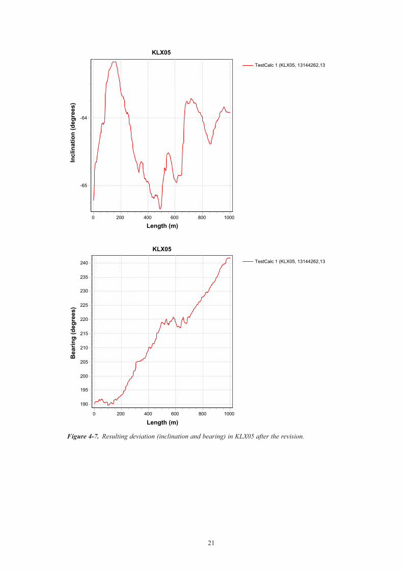
For the inclination the two magnetic/accelerometer loggings from 3 m borehole length are used. An automatic interpolation in Sicada is performed between TOC and 3 m. The resulting bearing and inclination from this example are shown in Figure 4-7. In most of the bore holes, however, the inclination readings from the magnetometer/accelerometer tool are used in the upper part of the borehole with casing, and only the bearing readings are replaced by inter-polated values.
The median values for inclination and bearing are calculated as the median values from the specified activities at each 3 m borehole length, including the surrounding values within ± 4.5 m borehole length. As an example, if the EG154-file specifies three logging activities, then each new value is calculated as the median value of 9 readings of inclination and bearing respectively. This procedure is implemented in Sicada.
4.4.3 Estimation of uncertainties in borehole deviation loggingsThe starting point in the calculation of deviation logging uncertainties is an estimate of the uncertainties of the measured quantities. The inclination- and bearing uncertainties are calculated as the 90th percentile of the whole population of differences between the new calculated deviation file (EG154 according to section 4.4.2) and all other deviation activities which are not ERROR-marked. This procedure is also included in Sicada. In boreholes with only one deviation activity, these uncertainties cannot be calculated. In these cases fixed values, defined as the maximum values from all core-drilled boreholes at Laxemar (except KLX15A and KLX16A which have been drilled after the revision) of the inclination uncertainty and the bearing uncertainty respectively are used. The values used are ΔI = 1.8° and ΔB = 4.9°. For Boremac measurements the values used for inclination uncertainty and bearing uncertainty are ΔI = 3.0° and ΔB = 6.0°. This assumption was based on expert judgement and comparison with straight line extrapolation, taking into account half the maximum values of uncertainty from the concerned boreholes.
For the boreholes which was not measured by any deviation method at all the uncertainty in inclination is calculated according to: –0.000092∙(BHL)2+0.049∙BHL+1.16+1.8. The uncertainty inbearingiscalculatedaccordingto:0.05∙BHL+2.5+4.9forboreholelengths≤100mand7.5+4.9 (i.e. a constant value of 12.4) for borehole lengths between 100 and 200 m.
A useful representation of the uncertainties involved in deviation logging is the “radius uncertainty”, defined as the radius (of a circle located in a plane perpendicular to the bore-hole axis) corresponding to the inclination- and bearing uncertainties. This quantity is a direct measure (in metres) of the uncertainty of the borehole location, and defines the shape of a cone surrounding the borehole.
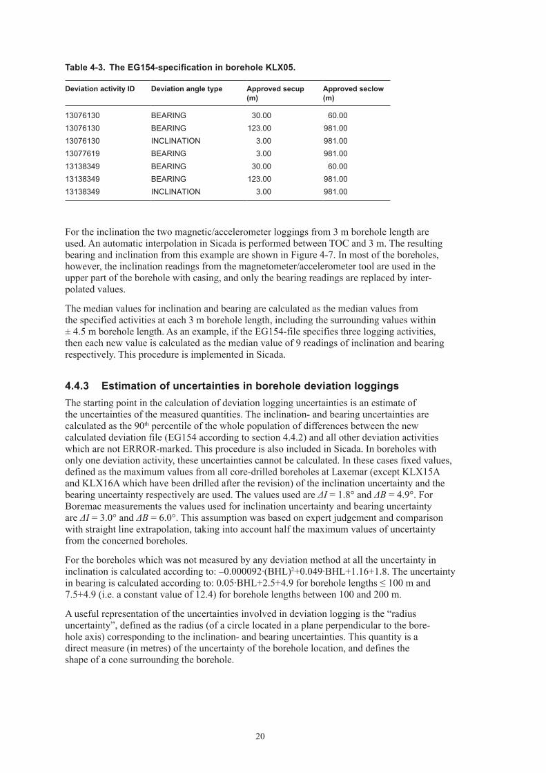
Table 4‑3. The EG154‑specification in borehole KLX05.
Deviation activity ID Deviation angle type Approved secup (m)
Approved seclow (m)
13076130 BEARING 30.00 60.0013076130 BEARING 123.00 981.0013076130 INCLINATION 3.00 981.0013077619 BEARING 3.00 981.0013138349 BEARING 30.00 60.0013138349 BEARING 123.00 981.0013138349 INCLINATION 3.00 981.00
21
TestCalc 1 (KLX05, 13144262,13
KLX05
Length (m)10008006004002000
Incl
inat
ion
(deg
rees
)
-64
-65
TestCalc 1 (KLX05, 13144262,13
KLX05
Length (m)10008006004002000
Bea
ring
(deg
rees
)
240
235
230
225
220
215
210
205
200
195
190
Figure 4‑7. Resulting deviation (inclination and bearing) in KLX05 after the revision.
22
The radius uncertainty is estimated as stated in equation (4-1).n
iiiin IBIMAXLLr
11 )cos()sin();sin()( (4-1)
where Li is the borehole length at measurement position i. This quantity is calculated auto matically in Sicada.
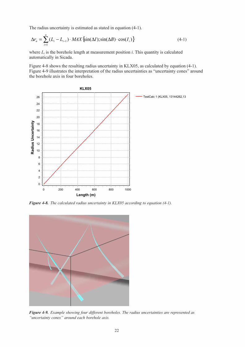
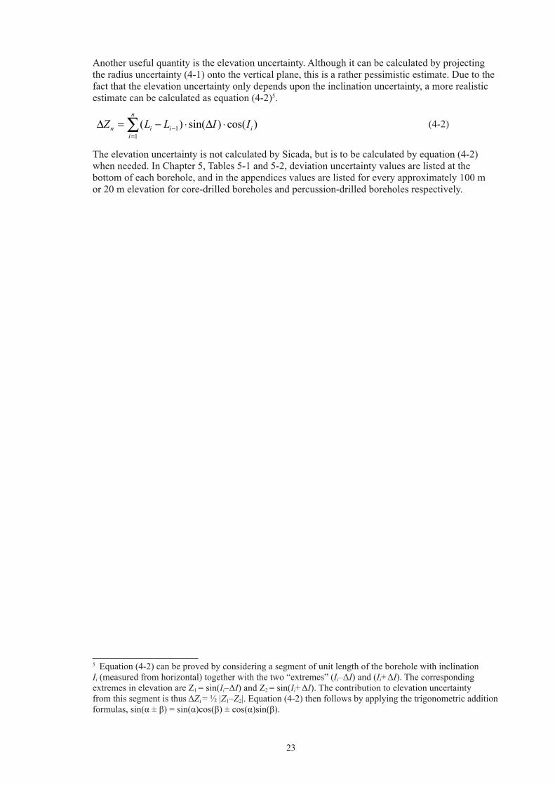
Figure 4-8 shows the resulting radius uncertainty in KLX05, as calculated by equation (4-1). Figure 4-9 illustrates the interpretation of the radius uncertainties as “uncertainty cones” around the borehole axis in four boreholes.
Figure 4‑8. The calculated radius uncertainty in KLX05 according to equation (4-1).
Figure 4‑9. Example showing four different boreholes. The radius uncertainties are represented as “uncertainty cones” around each borehole axis.
TestCalc 1 (KLX05, 13144262,13
KLX05
Length (m)10008006004002000
Rad
ius
Unc
erta
inty
26
24
22
20
18
16
14
12
10
8
6
4
2
0
23
Another useful quantity is the elevation uncertainty. Although it can be calculated by projecting the radius uncertainty (4-1) onto the vertical plane, this is a rather pessimistic estimate. Due to the fact that the elevation uncertainty only depends upon the inclination uncertainty, a more realistic estimate can be calculated as equation (4-2)5.
n
iiiin IILLZ
11 )cos()sin()( (4-2)
The elevation uncertainty is not calculated by Sicada, but is to be calculated by equation (4-2) when needed. In Chapter 5, Tables 5-1 and 5-2, deviation uncertainty values are listed at the bottom of each borehole, and in the appendices values are listed for every approximately 100 m or 20 m elevation for core-drilled boreholes and percussion-drilled boreholes respectively.
5 Equation (4-2) can be proved by considering a segment of unit length of the borehole with inclination Ii (measured from horizontal) together with the two “extremes” (Ii–ΔI) and (Ii+ΔI). The corresponding extremes in elevation are Z1 = sin(Ii–ΔI) and Z2 = sin(Ii+ΔI). The contribution to elevation uncertainty fromthissegmentisthusΔZi = ½ |Z1–Z2|. Equation (4-2) then follows by applying the trigonometric addition formulas,sin(α±β)=sin(α)cos(β)±cos(α)sin(β).
25
5 Results
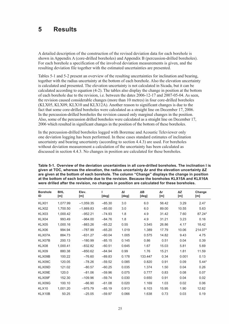
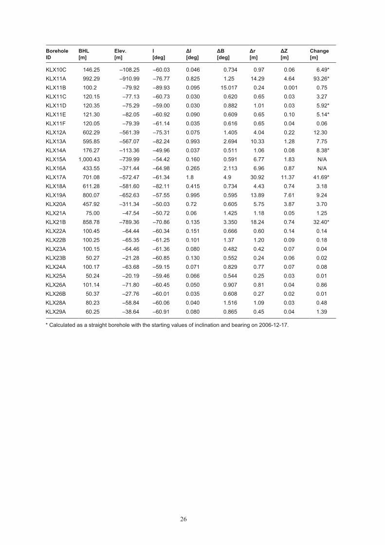
A detailed description of the construction of the revised deviation data for each borehole is shown in Appendix A (core-drilled boreholes) and Appendix B (percussion-drilled bore holes). For each borehole a specification of the involved deviation measurements is given, and the resulting deviation file together with the estimated uncertainties are presen ted.
Tables 5-1 and 5-2 present an overview of the resulting uncertainties for inclination and bearing, together with the radius uncertainty at the bottom of each borehole. Also the elevation uncertainty is calculated and presented. The elevation uncertainty is not calcu lated in Sicada, but it can be calculated according to equation (4-2). The tables also dis play the change in position at the bottom of each borehole due to the revision, i.e. bet ween the dates 2006-12-17 and 2007-05-04. As seen, the revision caused conside rable chan ges (more than 10 metres) in four core-drilled boreholes (KLX05, KLX09, KLX10 and KLX12A). Another reason to significant changes is due to the fact that some core-drilled boreholes were calculated as a straight line on December 17, 2006. In the percussion-drilled boreholes the revision caused only marginal changes in the position. Also, some of the percussion drilled boreholes were calculated as a straight line on December 17, 2006 which resulted in significant changes in the position of the bottom of these boreholes.
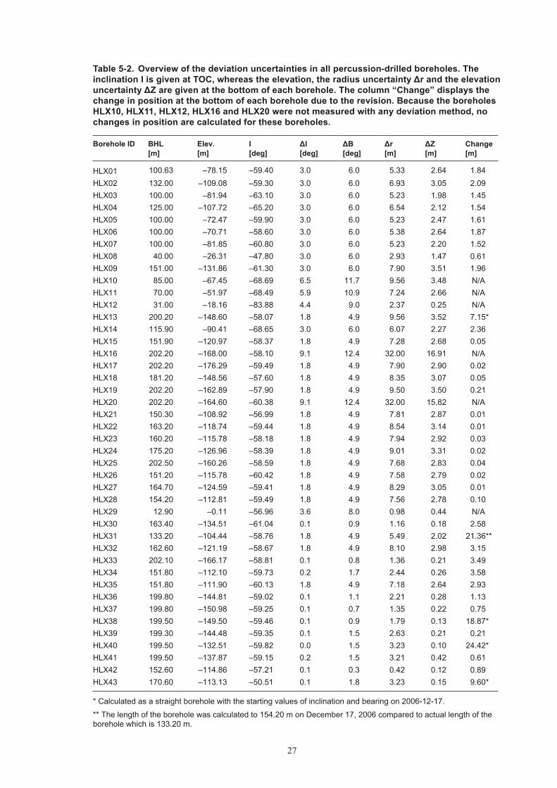
In the percussion-drilled boreholes logged with Boremac and Acoustic Televiewer only one deviation logging has been performed. In these cases standard estimates of inclination uncertainty and bearing uncer tain ty (according to section 4.4.3) are used. For boreholes without deviation measurement a calculation of the uncertainty has been calculated as discussed in section 4.4.3. No changes in position are calculated for these boreholes.
Table 5‑1. Overview of the deviation uncertainties in all core‑drilled boreholes. The inclination I is given at TOC, whereas the elevation, the radius uncertainty Δr and the elevation uncertainty ΔZ are given at the bottom of each borehole. The column “Change” displays the change in position at the bottom of each borehole due to the revision. Because the boreholes KLX15A and KLX16A were drilled after the revision, no changes in position are calculated for these boreholes.
Borehole ID
BHL [m]
Elev. [m]
I [deg]
ΔI [deg]
ΔB [deg]
Δr [m]
ΔZ [m]
Change[m]
KLX01 1,077.99 –1,059.35 –85.30 3.0 6.0 56.42 3.29 2.47KLX02 1,700.50 –1,669.83 –85.00 3.0 6.0 89.00 10.55 5.63KLX03 1,000.42 –952.21 –74.93 1.8 4.9 31.42 7.60 87.24*KLX04 993.49 –964.00 –84.76 1.8 4.9 31.21 3.23 0.16KLX05 1,000.16 –883.26 –65.22 0.55 3.545 26.86 4.17 18.42KLX06 994.94 –787.99 –65.20 1.019 1.389 17.79 10.06 214.07*KLX07A 884.73 –631.27 –60.04 1.005 0.575 14.82 9.43 4.75KLX07B 200.13 –180.99 –85.15 0.145 0.86 0.51 0.04 0.39KLX08 1,000.41 –832.82 –60.51 0.645 1.67 15.03 5.81 5.69KLX09 880.38 –850.62 –84.94 0.99 1.76 15.21 1.81 11.59KLX09B 100.22 –76.60 –89.83 0.178 133.447 0.34 0.001 0.13KLX09C 120.05 –78.26 –59.52 0.085 0.820 0.91 0.09 5.44*KLX09D 121.02 –80.57 –60.25 0.035 1.374 1.50 0.04 0.26KLX09E 120.0 –81.06 –59.96 0.075 0.777 0.83 0.08 0.07KLX09F 152.30 –109.96 –59.74 0.030 0.650 0.91 0.04 0.02KLX09G 100.10 –66.90 –61.08 0.020 1.169 1.03 0.02 0.06KLX10 1,001.20 –975.79 –85.19 0.913 6.103 15.95 1.90 12.62KLX10B 50.25 –25.05 –59.97 0.066 1.638 0.73 0.03 0.19
26
Borehole ID
BHL [m]
Elev. [m]
I [deg]
ΔI [deg]
ΔB [deg]
Δr [m]
ΔZ [m]
Change[m]
KLX10C 146.25 –108.25 –60.03 0.046 0.734 0.97 0.06 6.49*KLX11A 992.29 –910.99 –76.77 0.825 1.25 14.29 4.64 93.26*KLX11B 100.2 –79.92 –89.93 0.095 15.017 0.24 0.001 0.75KLX11C 120.15 –77.13 –60.73 0.030 0.620 0.65 0.03 3.27KLX11D 120.35 –75.29 –59.00 0.030 0.882 1.01 0.03 5.92*KLX11E 121.30 –82.05 –60.92 0.090 0.609 0.65 0.10 5.14*KLX11F 120.05 –79.39 –61.14 0.035 0.616 0.65 0.04 0.06KLX12A 602.29 –561.39 –75.31 0.075 1.405 4.04 0.22 12.30KLX13A 595.85 –567.07 –82.24 0.993 2.694 10.33 1.28 7.75KLX14A 176.27 –113.36 –49.96 0.037 0.511 1.06 0.08 8.38*KLX15A 1,000.43 –739.99 –54.42 0.160 0.591 6.77 1.83 N/AKLX16A 433.55 –371.44 –64.98 0.265 2.113 6.96 0.87 N/AKLX17A 701.08 –572.47 –61.34 1.8 4.9 30.92 11.37 41.69*KLX18A 611.28 –581.60 –82.11 0.415 0.734 4.43 0.74 3.18KLX19A 800.07 –652.63 –57.55 0.995 0.595 13.89 7.61 9.24KLX20A 457.92 –311.34 –50.03 0.72 0.605 5.75 3.87 3.70KLX21A 75.00 –47.54 –50.72 0.06 1.425 1.18 0.05 1.25KLX21B 858.78 –789.36 –70.86 0.135 3.350 18.24 0.74 32.40*KLX22A 100.45 –64.44 –60.34 0.151 0.666 0.60 0.14 0.14KLX22B 100.25 –65.35 –61.25 0.101 1.37 1.20 0.09 0.18KLX23A 100.15 –64.46 –61.36 0.080 0.482 0.42 0.07 0.04KLX23B 50.27 –21.28 –60.85 0.130 0.552 0.24 0.06 0.02KLX24A 100.17 –63.68 –59.15 0.071 0.829 0.77 0.07 0.08KLX25A 50.24 –20.19 –59.46 0.066 0.544 0.25 0.03 0.01KLX26A 101.14 –71.80 –60.45 0.050 0.907 0.81 0.04 0.86KLX26B 50.37 –27.76 –60.01 0.035 0.608 0.27 0.02 0.01KLX28A 80.23 –58.84 –60.06 0.040 1.516 1.09 0.03 0.48KLX29A 60.25 –38.64 –60.91 0.080 0.865 0.45 0.04 1.39
* Calculated as a straight borehole with the starting values of inclination and bearing on 2006-12-17.
27
Table 5‑2. Overview of the deviation uncertainties in all percussion‑drilled bore holes. The inclination I is given at TOC, whereas the elevation, the radius uncer tainty Δr and the elevation uncertainty ΔZ are given at the bottom of each bore hole. The column “Change” displays the change in position at the bottom of each borehole due to the revision. Because the boreholes HLX10, HLX11, HLX12, HLX16 and HLX20 were not measured with any deviation method, no changes in position are calculated for these boreholes.
Borehole ID BHL [m]
Elev. [m]
I [deg]
ΔI [deg]
ΔB [deg]
Δr [m]
ΔZ [m]
Change [m]
HLX01 100.63 –78.15 –59.40 3.0 6.0 5.33 2.64 1.84HLX02 132.00 –109.08 –59.30 3.0 6.0 6.93 3.05 2.09HLX03 100.00 –81.94 –63.10 3.0 6.0 5.23 1.98 1.45HLX04 125.00 –107.72 –65.20 3.0 6.0 6.54 2.12 1.54HLX05 100.00 –72.47 –59.90 3.0 6.0 5.23 2.47 1.61HLX06 100.00 –70.71 –58.60 3.0 6.0 5.38 2.64 1.87HLX07 100.00 –81.85 –60.80 3.0 6.0 5.23 2.20 1.52HLX08 40.00 –26.31 –47.80 3.0 6.0 2.93 1.47 0.61HLX09 151.00 –131.86 –61.30 3.0 6.0 7.90 3.51 1.96HLX10 85.00 –67.45 –68.69 6.5 11.7 9.56 3.48 N/AHLX11 70.00 –51.97 –68.49 5.9 10.9 7.24 2.66 N/AHLX12 31.00 –18.16 –83.88 4.4 9.0 2.37 0.25 N/A HLX13 200.20 –148.60 –58.07 1.8 4.9 9.56 3.52 7.15*HLX14 115.90 –90.41 –68.65 3.0 6.0 6.07 2.27 2.36HLX15 151.90 –120.97 –58.37 1.8 4.9 7.28 2.68 0.05HLX16 202.20 –168.00 –58.10 9.1 12.4 32.00 16.91 N/A HLX17 202.20 –176.29 –59.49 1.8 4.9 7.90 2.90 0.02HLX18 181.20 –148.56 –57.60 1.8 4.9 8.35 3.07 0.05HLX19 202.20 –162.89 –57.90 1.8 4.9 9.50 3.50 0.21HLX20 202.20 –164.60 –60.38 9.1 12.4 32.00 15.82 N/A HLX21 150.30 –108.92 –56.99 1.8 4.9 7.81 2.87 0.01HLX22 163.20 –118.74 –59.44 1.8 4.9 8.54 3.14 0.01HLX23 160.20 –115.78 –58.18 1.8 4.9 7.94 2.92 0.03HLX24 175.20 –126.96 –58.39 1.8 4.9 9.01 3.31 0.02HLX25 202.50 –160.26 –58.59 1.8 4.9 7.68 2.83 0.04HLX26 151.20 –115.78 –60.42 1.8 4.9 7.58 2.79 0.02HLX27 164.70 –124.59 –59.41 1.8 4.9 8.29 3.05 0.01HLX28 154.20 –112.81 –59.49 1.8 4.9 7.56 2.78 0.10HLX29 12.90 –0.11 –56.96 3.6 8.0 0.98 0.44 N/AHLX30 163.40 –134.51 –61.04 0.1 0.9 1.16 0.18 2.58HLX31 133.20 –104.44 –58.76 1.8 4.9 5.49 2.02 21.36**HLX32 162.60 –121.19 –58.67 1.8 4.9 8.10 2.98 3.15HLX33 202.10 –166.17 –58.81 0.1 0.8 1.36 0.21 3.49HLX34 151.80 –112.10 –59.73 0.2 1.7 2.44 0.26 3.58HLX35 151.80 –111.90 –60.13 1.8 4.9 7.18 2.64 2.93HLX36 199.80 –144.81 –59.02 0.1 1.1 2.21 0.28 1.13HLX37 199.80 –150.98 –59.25 0.1 0.7 1.35 0.22 0.75HLX38 199.50 –149.50 –59.46 0.1 0.9 1.79 0.13 18.87*HLX39 199.30 –144.48 –59.35 0.1 1.5 2.63 0.21 0.21HLX40 199.50 –132.51 –59.82 0.0 1.5 3.23 0.10 24.42*HLX41 199.50 –137.87 –59.15 0.2 1.5 3.21 0.42 0.61HLX42 152.60 –114.86 –57.21 0.1 0.3 0.42 0.12 0.89HLX43 170.60 –113.13 –50.51 0.1 1.8 3.23 0.15 9.60*
* Calculated as a straight borehole with the starting values of inclination and bearing on 2006-12-17.
** The length of the borehole was calculated to 154.20 m on December 17, 2006 compared to actual length of the borehole which is 133.20 m.
Appendices attached on CD
Appendix A. Details of the core‑drilled boreholesAppendix B. Details of the percussion‑drilled boreholesReading instructions for the appendicesFor each borehole the appendix starts with a technical description, followed by a des cription of the deviation logging activities and the used strategy for including (and excluding) deviation data in the final calculation. Parts of the text is identical to the text in the Sicada comments (in swedish language).
The key in the discussion of deviation logging activities is the Activity ID code, which is a unique number specifying an activity stored in Sicada. For each bore hole Table 1 lists the involved activities. Note, that Table 1 always contains one additional activity compared to the actual number of deviation logging activities in a borehole. This is due to the fact that the activity Borehole deviation multiple measurements (EG154) appears in Table 1. It should also be noted, that in many cases some activities are redundant, in the sence that they are based on the same deviation logging. This is the case for most of the percussion drilled boreholes in Appendix B, for which one of the activities is ERROR-marked. This activity was initially stored using wrong corrections for magnetic declination, and was therefore at a later date substituted by a new, correct, data set. Because data cannot be deleted from Sicada, these activities still appear in Table 1, although ERROR-marked.
Table 2 shows the content of the file EG154 Borehole deviation multiple measurements, described in section 4.4.2.
Table 3 contains a subset of the object_location file, which is an output from Sicada. The original object_location file contains coordinate information for every three meter borehole length. In Table 3 the information is reduced to every approximately 100 m elevation (Appendix A) or 20 m elevation (Appendix B). Table 3 contains an additional column Elevation_uncert which contains the elevation uncertainty calculated by equation (4-2). This parameter is not calculated in Sicada, but added afterwards to the tables.
Appendix A KLX01
31
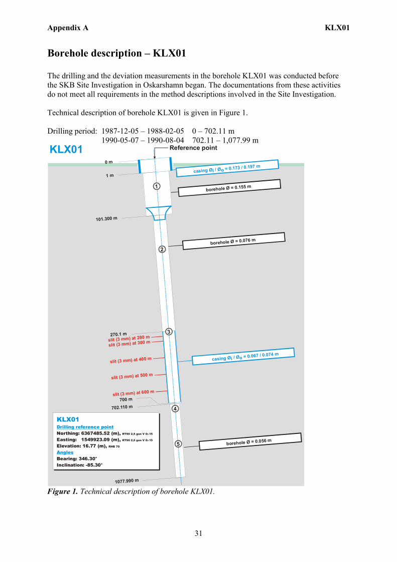
Borehole description – KLX01 The drilling and the deviation measurements in the borehole KLX01 was conducted before the SKB Site Investigation in Oskarshamn began. The documentations from these activities do not meet all requirements in the method descriptions involved in the Site Investigation. Technical description of borehole KLX01 is given in Figure 1. Drilling period: 1987-12-05 – 1988-02-05 0 – 702.11 m 1990-05-07 – 1990-08-04 702.11 – 1,077.99 m
1 m
0 m
101.300 m
270.1 m
700 m
702.110 m
1077.990 m
slit (3 mm) at 280 m
slit (3 mm) at 300 m
slit (3 mm) at 400 m
slit (3 mm) at 500 m
slit (3 mm) at 600 m
casing = 0.067 / 0.074 mØi / Øo
casing = 0.173 / 0.197 mØi / Øo
4
5
3
2
1
borehole = 0.076 mØ
borehole = 0.056 mØ
borehole = 0.155 mØ
Northing: 6367485.52 (m), Easting: 1549923.09 (m), Elevation: 16.77 (m),
Bearing: 346.30°Inclination: -85.30°
RT90 2,5 gon V 0:-15
RT90 2,5 gon V 0:-15
RHB 70
KLX01Drilling reference point
Angles
KLX01 Reference point
Figure 1. Technical description of borehole KLX01.
Appendix A KLX01
32
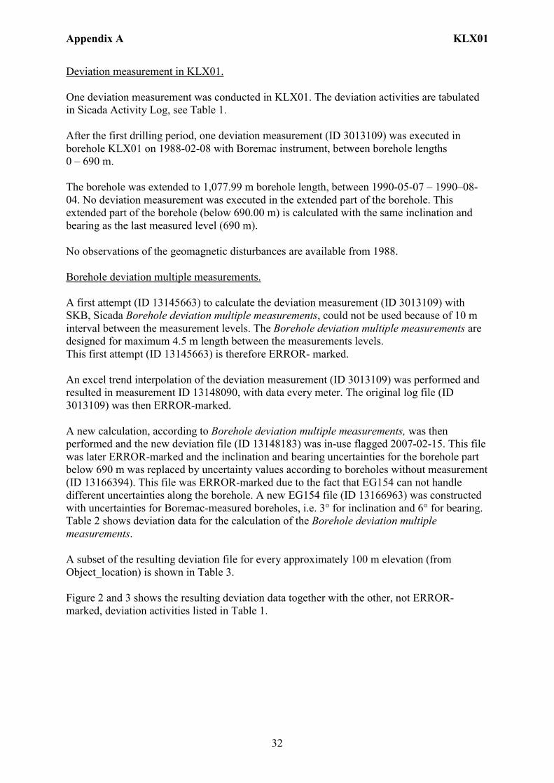
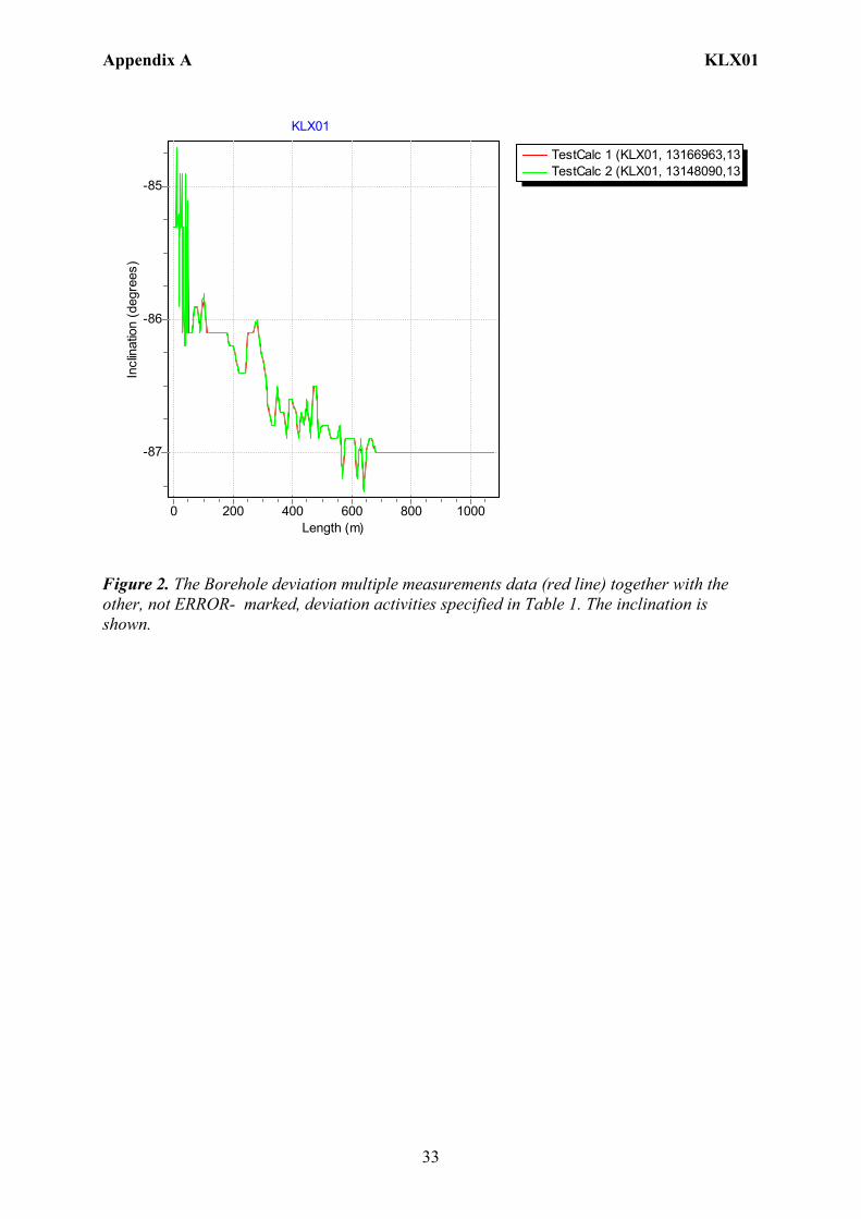
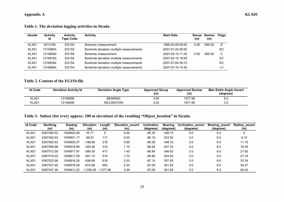
Deviation measurement in KLX01. One deviation measurement was conducted in KLX01. The deviation activities are tabulated in Sicada Activity Log, see Table 1. After the first drilling period, one deviation measurement (ID 3013109) was executed in borehole KLX01 on 1988-02-08 with Boremac instrument, between borehole lengths 0 – 690 m. The borehole was extended to 1,077.99 m borehole length, between 1990-05-07 – 1990–08-04. No deviation measurement was executed in the extended part of the borehole. This extended part of the borehole (below 690.00 m) is calculated with the same inclination and bearing as the last measured level (690 m). No observations of the geomagnetic disturbances are available from 1988. Borehole deviation multiple measurements. A first attempt (ID 13145663) to calculate the deviation measurement (ID 3013109) with SKB, Sicada Borehole deviation multiple measurements, could not be used because of 10 m interval between the measurement levels. The Borehole deviation multiple measurements are designed for maximum 4.5 m length between the measurements levels. This first attempt (ID 13145663) is therefore ERROR- marked. An excel trend interpolation of the deviation measurement (ID 3013109) was performed and resulted in measurement ID 13148090, with data every meter. The original log file (ID 3013109) was then ERROR-marked. A new calculation, according to Borehole deviation multiple measurements, was then performed and the new deviation file (ID 13148183) was in-use flagged 2007-02-15. This file was later ERROR-marked and the inclination and bearing uncertainties for the borehole part below 690 m was replaced by uncertainty values according to boreholes without measurement (ID 13166394). This file was ERROR-marked due to the fact that EG154 can not handle different uncertainties along the borehole. A new EG154 file (ID 13166963) was constructed with uncertainties for Boremac-measured boreholes, i.e. 3° for inclination and 6° for bearing. Table 2 shows deviation data for the calculation of the Borehole deviation multiple measurements. A subset of the resulting deviation file for every approximately 100 m elevation (from Object_location) is shown in Table 3. Figure 2 and 3 shows the resulting deviation data together with the other, not ERROR-marked, deviation activities listed in Table 1.
Appendix A KLX01
33
TestCalc 1 (KLX01, 13166963,13TestCalc 2 (KLX01, 13148090,13
KLX01
Length (m)10008006004002000
Incl
inat
ion
(deg
rees
)
-85
-86
-87
Figure 2. The Borehole deviation multiple measurements data (red line) together with the other, not ERROR- marked, deviation activities specified in Table 1. The inclination is shown.
Appendix A KLX01
34
TestCalc 1 (KLX01, 13166963,13TestCalc 2 (KLX01, 13148090,13
KLX01
Length (m)10008006004002000
Bear
ing
(deg
rees
)
1614121086420
-2-4-6-8
-10-12-14-16
TestCalc 1 (KLX01, 13166963,13TestCalc 2 (KLX01, 13148090,13
KLX01
Length (m)10008006004002000
Bear
ing
(deg
rees
)
364362360358356354352350348346344342340338336334332330328
Figure 3. The Borehole deviation multiple measurements data (red line) together with the other, not ERROR- marked, deviation activities specified in Table 1. The upper diagram shows the bearing greater than 0° and the lower diagram shows the bearing below 360°.
Appendix A KLX01
35
Table 1. The deviation logging activities in Sicada.
Idcode Activity Id
Activity Type Code
Activity Start Date Secup(m)
Seclow(m)
Flags
KLX01 3013109 EG155 Boremac measurement 1988-02-08 00:00 0.00 690.00 E KLX01 13145663 EG154 Borehole deviation multiple measurements 2007-01-24 08:00 EC KLX01 13148090 EG155 Boremac measurement 2007-02-15 11:30 0.00 690.00 C KLX01 13148183 EG154 Borehole deviation multiple measurements 2007-02-15 16:00 EC KLX01 13166394 EG154 Borehole deviation multiple measurements 2007-07-04 09:15 EC KLX01 13166963 EG154 Borehole deviation multiple measurements 2007-07-10 14:30 I C
Table 2. Content of the EG154-file.
Id Code Deviation Activity Id Deviation Angle Type Approved Secup (m)
Approved Seclow (m)
Man Estim Angle Uncert (degrees)
KLX01 13148090 BEARING 3.00 1077.99 6.0 KLX01 13148090 INCLINATION 3.00 1077.99 3.0
Table 3. Subset (for every approx. 100 m elevation) of the resulting “Object_location” in Sicada. Id Code
Northing
(m) Easting
(m) Elevation
(m) Length
(m) Elevation_uncert
(m) Inclination (degrees)
Bearing (degrees)
Inclination_uncert(degrees)
Bearing_uncert (degrees)
Radius_uncert (m)
KLX01 6367485.52 1549923.09 16.77 0 0.00 -85.30 348.73 3.0 6.0 0 KLX01 6367493.93 1549921.17 -99.91 117 0.45 -86.10 353.93 3.0 6.0 6.12 KLX01 6367500.53 1549920.37 -198.68 216 0.80 -86.36 348.33 3.0 6.0 11.15 KLX01 6367506.98 1549918.86 -300.46 318 1.15 -86.64 357.33 3.0 6.0 16.49 KLX01 6367512.59 1549917.97 -399.30 417 1.45 -86.84 346.63 3.0 6.0 21.82 KLX01 6367518.32 1549917.09 -501.14 519 1.75 -86.80 354.93 3.0 6.0 27.16 KLX01 6367523.56 1549916.26 -599.99 618 2.03 -87.14 357.93 3.0 6.0 32.34 KLX01 6367527.45 1549916.09 -674.89 693 2.23 -87.00 351.83 3.0 6.0 36.27 KLX01 6367547.39 1549913.22 -1,059.35 1,077.99 3.29 -87.00 351.83 3.0 6.0 56.42
Appendix A KLX02
36
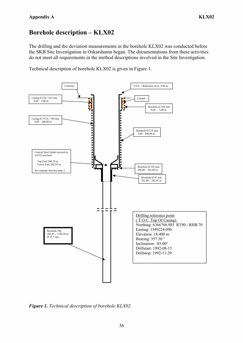
Borehole description – KLX02 The drilling and the deviation measurements in the borehole KLX02 was conducted before the SKB Site Investigation in Oskarshamn began. The documentations from these activities do not meet all requirements in the method descriptions involved in the Site Investigation. Technical description of borehole KLX02 is given in Figure 1.
Figure 1. Technical description of borehole KLX02.
T.O.C = Reference level 0.00 m
Borehole Ø 304 mm 0,40 - 3,00 m
Borehole Ø 215 mm 3,00 – 200,80 m
Borehole NQ 202,95 – 1700,50 m Ø 75,7 mm
Cement
Conical Steel Guide lowered in a Ø 92 mm hole. Top End: 200,70 m Lower End: 202,95 m See separate drawing page 2.
Casing Ø 254 / 241 mm 0,40 – 3,00 m
Casing Ø 197,8 / 194 mm 0,00 – 200,80 m
Borehole Ø 92 mm 201,00 – 202,95 m
Concrete
Borehole Ø 165 mm 200,80 – 201,00 m
Drilling reference point ( T.O.C. Top Of Casing). Northing: 6366768.985 RT90 - RHB 70 Easting: 1549224.090 Elevation: 18.400 m Bearing: 357.30 ° Inclination: -85.00° Drillstart: 1992-08-15 Drillstop: 1992-11-29
Appendix A KLX02
37
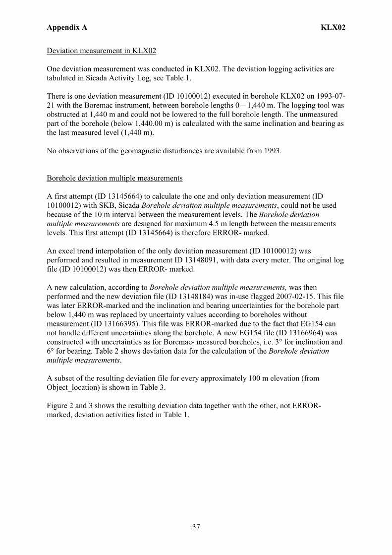
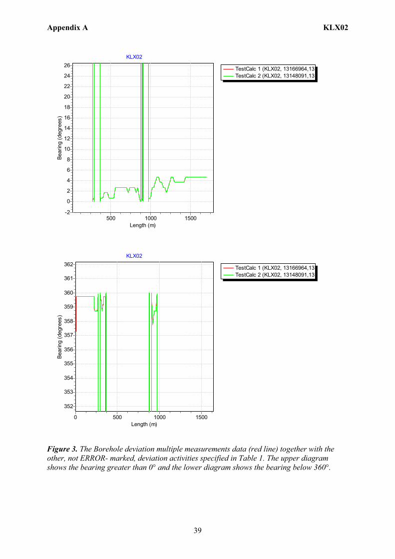
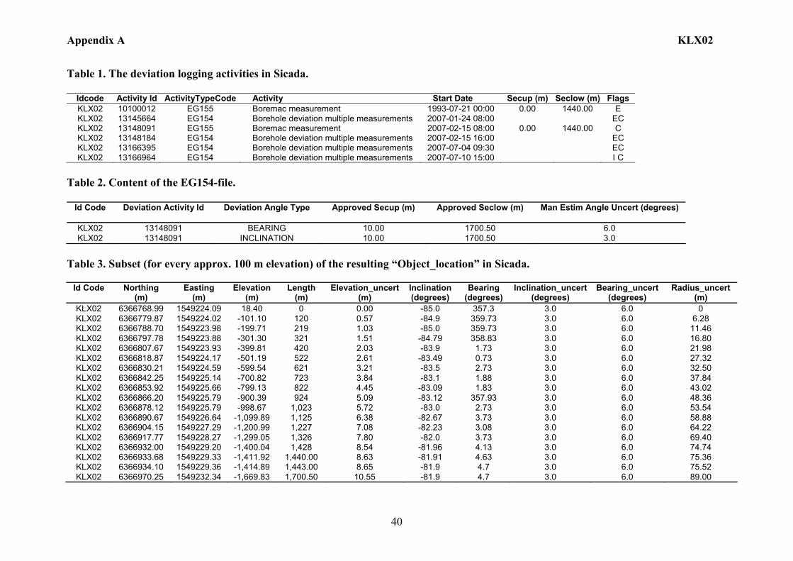
Deviation measurement in KLX02 One deviation measurement was conducted in KLX02. The deviation logging activities are tabulated in Sicada Activity Log, see Table 1. There is one deviation measurement (ID 10100012) executed in borehole KLX02 on 1993-07-21 with the Boremac instrument, between borehole lengths 0 – 1,440 m. The logging tool was obstructed at 1,440 m and could not be lowered to the full borehole length. The unmeasured part of the borehole (below 1,440.00 m) is calculated with the same inclination and bearing as the last measured level (1,440 m). No observations of the geomagnetic disturbances are available from 1993. Borehole deviation multiple measurements A first attempt (ID 13145664) to calculate the one and only deviation measurement (ID 10100012) with SKB, Sicada Borehole deviation multiple measurements, could not be used because of the 10 m interval between the measurement levels. The Borehole deviation multiple measurements are designed for maximum 4.5 m length between the measurements levels. This first attempt (ID 13145664) is therefore ERROR- marked. An excel trend interpolation of the only deviation measurement (ID 10100012) was performed and resulted in measurement ID 13148091, with data every meter. The original log file (ID 10100012) was then ERROR- marked. A new calculation, according to Borehole deviation multiple measurements, was then performed and the new deviation file (ID 13148184) was in-use flagged 2007-02-15. This file was later ERROR-marked and the inclination and bearing uncertainties for the borehole part below 1,440 m was replaced by uncertainty values according to boreholes without measurement (ID 13166395). This file was ERROR-marked due to the fact that EG154 can not handle different uncertainties along the borehole. A new EG154 file (ID 13166964) was constructed with uncertainties as for Boremac- measured boreholes, i.e. 3° for inclination and 6° for bearing. Table 2 shows deviation data for the calculation of the Borehole deviation multiple measurements. A subset of the resulting deviation file for every approximately 100 m elevation (from Object_location) is shown in Table 3. Figure 2 and 3 shows the resulting deviation data together with the other, not ERROR-marked, deviation activities listed in Table 1.
Appendix A KLX02
38
TestCalc 1 (KLX02, 13166964,13TestCalc 2 (KLX02, 13148091,13
KLX02
Length (m)150010005000
Incl
inat
ion
(deg
rees
)
-82
-83
-84
-85
Figure 2. The Borehole deviation multiple measurements data (red line) together with the other, not ERROR- marked, deviation activities specified in Table 1. The inclination is shown.
Appendix A KLX02
39
TestCalc 1 (KLX02, 13166964,13TestCalc 2 (KLX02, 13148091,13
KLX02
Length (m)15001000500
Bear
ing
(deg
rees
)26
24
22
20
18
16
14
12
10
8
6
4
2
0
-2
TestCalc 1 (KLX02, 13166964,13TestCalc 2 (KLX02, 13148091,13
KLX02
Length (m)150010005000
Bear
ing
(deg
rees
)
362
361
360
359
358
357
356
355
354
353
352
Figure 3. The Borehole deviation multiple measurements data (red line) together with the other, not ERROR- marked, deviation activities specified in Table 1. The upper diagram shows the bearing greater than 0° and the lower diagram shows the bearing below 360°.
Appendix A KLX02
40
Table 1. The deviation logging activities in Sicada.
Idcode Activity Id ActivityTypeCode Activity Start Date Secup (m) Seclow (m) Flags KLX02 10100012 EG155 Boremac measurement 1993-07-21 00:00 0.00 1440.00 E KLX02 13145664 EG154 Borehole deviation multiple measurements 2007-01-24 08:00 EC KLX02 13148091 EG155 Boremac measurement 2007-02-15 08:00 0.00 1440.00 C KLX02 13148184 EG154 Borehole deviation multiple measurements 2007-02-15 16:00 EC KLX02 13166395 EG154 Borehole deviation multiple measurements 2007-07-04 09:30 EC KLX02 13166964 EG154 Borehole deviation multiple measurements 2007-07-10 15:00 I C
Table 2. Content of the EG154-file.
Id Code Deviation Activity Id Deviation Angle Type Approved Secup (m) Approved Seclow (m) Man Estim Angle Uncert (degrees)
KLX02 13148091 BEARING 10.00 1700.50 6.0 KLX02 13148091 INCLINATION 10.00 1700.50 3.0
Table 3. Subset (for every approx. 100 m elevation) of the resulting “Object_location” in Sicada.
Id Code
Northing (m)
Easting (m)
Elevation (m)
Length (m)
Elevation_uncert(m)
Inclination (degrees)
Bearing (degrees)
Inclination_uncert(degrees)
Bearing_uncert (degrees)
Radius_uncert (m)
KLX02 6366768.99 1549224.09 18.40 0 0.00 -85.0 357.3 3.0 6.0 0 KLX02 6366779.87 1549224.02 -101.10 120 0.57 -84.9 359.73 3.0 6.0 6.28 KLX02 6366788.70 1549223.98 -199.71 219 1.03 -85.0 359.73 3.0 6.0 11.46 KLX02 6366797.78 1549223.88 -301.30 321 1.51 -84.79 358.83 3.0 6.0 16.80 KLX02 6366807.67 1549223.93 -399.81 420 2.03 -83.9 1.73 3.0 6.0 21.98 KLX02 6366818.87 1549224.17 -501.19 522 2.61 -83.49 0.73 3.0 6.0 27.32 KLX02 6366830.21 1549224.59 -599.54 621 3.21 -83.5 2.73 3.0 6.0 32.50 KLX02 6366842.25 1549225.14 -700.82 723 3.84 -83.1 1.88 3.0 6.0 37.84 KLX02 6366853.92 1549225.66 -799.13 822 4.45 -83.09 1.83 3.0 6.0 43.02 KLX02 6366866.20 1549225.79 -900.39 924 5.09 -83.12 357.93 3.0 6.0 48.36 KLX02 6366878.12 1549225.79 -998.67 1,023 5.72 -83.0 2.73 3.0 6.0 53.54 KLX02 6366890.67 1549226.64 -1,099.89 1,125 6.38 -82.67 3.73 3.0 6.0 58.88 KLX02 6366904.15 1549227.29 -1,200.99 1,227 7.08 -82.23 3.08 3.0 6.0 64.22 KLX02 6366917.77 1549228.27 -1,299.05 1,326 7.80 -82.0 3.73 3.0 6.0 69.40 KLX02 6366932.00 1549229.20 -1,400.04 1,428 8.54 -81.96 4.13 3.0 6.0 74.74 KLX02 6366933.68 1549229.33 -1,411.92 1,440.00 8.63 -81.91 4.63 3.0 6.0 75.36 KLX02 6366934.10 1549229.36 -1,414.89 1,443.00 8.65 -81.9 4.7 3.0 6.0 75.52 KLX02 6366970.25 1549232.34 -1,669.83 1,700.50 10.55 -81.9 4.7 3.0 6.0 89.00
Appendix A KLX03
41
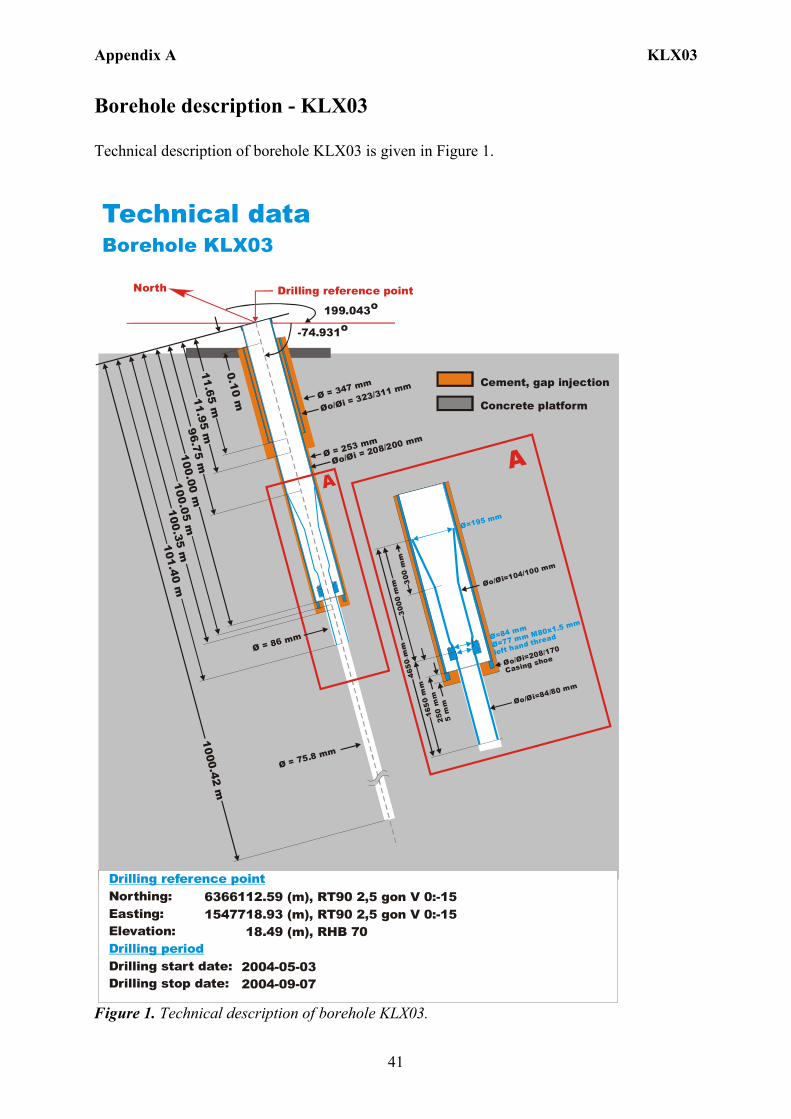
Borehole description - KLX03 Technical description of borehole KLX03 is given in Figure 1. Technical dataBorehole KLX03
6366112.59 (m),1547718.93 (m), 18.49 (m),
2004-05-03 2004-09-07
RT90 2,5 gon V 0:-15 RT90 2,5 gon V 0:-15 RHB 70
Northing:Easting:Elevation:
Drilling start date:Drilling stop date:
Drilling reference point
Drilling period
North
199.043o
-74.931o
Drilling reference point
Cement, gap injection
Concrete platformØ = 347 mm
Ø = 253 mm
Øo/ = 323/311 mm
Øi
Øo/ = 208/200 mm
Øi
Ø = 75.8 mm
A
0.10 m
Ø = 86 mm
11.95 m
100.05 m11.65 m
100.00 m96.75 m
101.40 m100.35 m
1000.42 m
Ø=195 mm
Øo/ =104/100 mm
Øi
Ø=84 mm
Ø=77 mm M80x1.5 mm
left hand thread
Øo/Øi=208/170
Casing shoe
Øo/ =84/80 mmØi
5 m
m
300
mm
3000
mm
4650
mm
1650
mm
A25
0 m
m
Figure 1. Technical description of borehole KLX03.
Appendix A KLX03
42
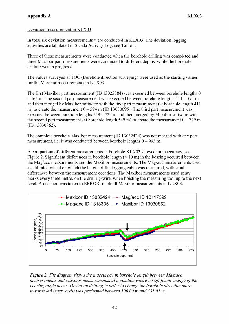
Deviation measurement in KLX03 In total six deviation measurements were conducted in KLX03. The deviation logging activities are tabulated in Sicada Activity Log, see Table 1. Three of those measurements were conducted when the borehole drilling was completed and three Maxibor part measurements were conducted to different depths, while the borehole drilling was in progress. The values surveyed at TOC (Borehole direction surveying) were used as the starting values for the Maxibor measurements in KLX03. The first Maxibor part measurement (ID 13025384) was executed between borehole lengths 0 – 465 m. The second part measurement was executed between borehole lengths 411 – 594 m and then merged by Maxibor software with the first part measurement (at borehole length 411 m) to create the measurement 0 – 594 m (ID 13030095). The third part measurement was executed between borehole lengths 549 – 729 m and then merged by Maxibor software with the second part measurement (at borehole length 549 m) to create the measurement 0 – 729 m (ID 13030862). The complete borehole Maxibor measurement (ID 13032424) was not merged with any part measurement, i.e. it was conducted between borehole lengths 0 – 993 m. A comparison of different measurements in borehole KLX03 showed an inaccuracy, see Figure 2. Significant differences in borehole length (> 10 m) in the bearing occurred between the Mag/acc measurements and the Maxibor measurements. The Mag/acc measurements used a calibrated wheel on which the length of the logging cable was measured, with small differences between the measurement occations. The Maxibor measurements used spray marks every three metre, on the drill rig-wire, when hoisting the measuring tool up to the next level. A decision was taken to ERROR- mark all Maxibor measurements in KLX03.
195200205210215220225230235240245250
0 75 150 225 300 375 450 525 600 675 750 825 900 975
Borehole depth (m)
Bea
ring
(deg
rees
)
Maxibor ID 13032424 Mag/acc ID 13117399Mag/acc ID 1318335 Maxibor ID 13030862
Figure 2. The diagram shows the inaccuracy in borehole length between Mag/acc measurements and Maxibor measurements, at a position where a significant change of the bearing angle occur. Deviation drilling in order to change the borehole direction more towards left (eastwards) was performed between 500.00 m and 531.01 m.
Appendix A KLX03
43
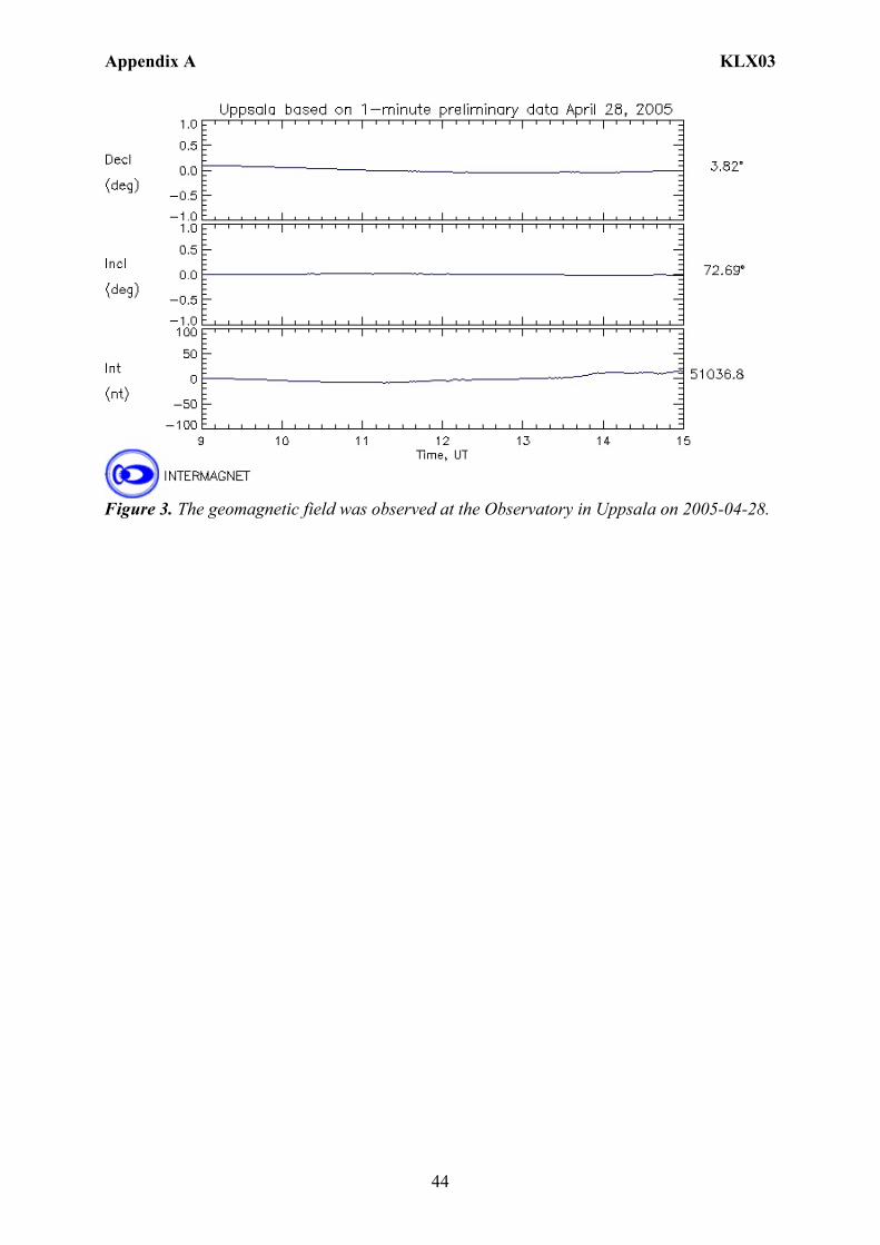
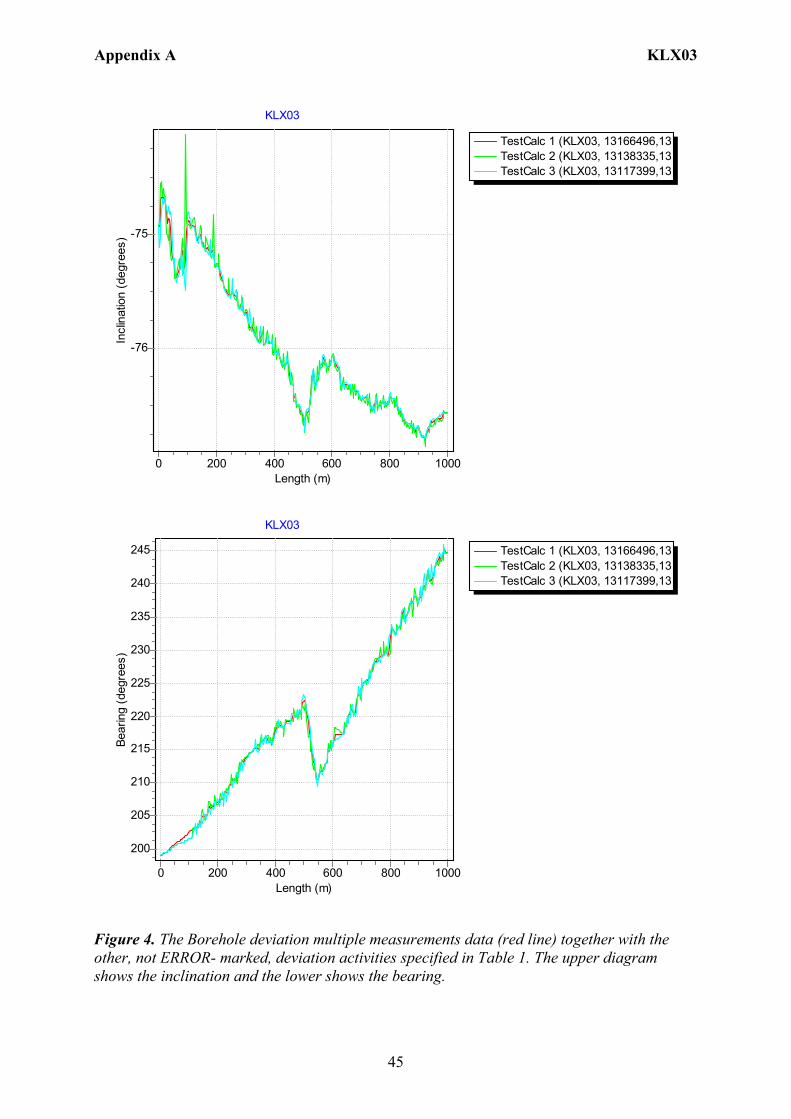
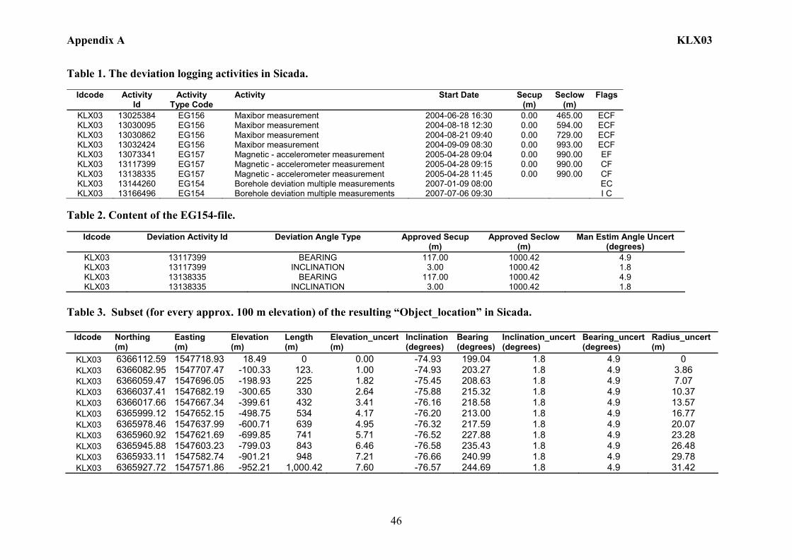
Mag/acc measurement (ID 13073341) was bug reported and ERROR- marked, due to wrongly correction for magnetic declination and meridian convergence. But the raw data from that measurement was re-used, without correction for magnetic declination and meridian convergence, to calculate the correct measurement (ID 13117399). The two Mac/acc measurements (ID 13117399, 13138335) were executed down and up the borehole length, with the Flexit instrument. Corrections of measured data are documented in the File References (Sicada) for the measurements. No geomagnetic disturbances exceeding 0.5 degrees were observed on the date of the Mag/acc measuring, see Figure 3. Borehole deviation multiple measurements. In the calculation of Borehole deviation multiple measurements (ID 13144260) the two Mag/acc measurements (ID 13117399, ID 13138335) were used. Table 2 shows all deviation data for the calculation. A subset of the resulting deviation file for every approximately 100 m elevation (from Object_location) is shown in Table 3. The inclination and bearing uncertainties were calculated automatically, and based on these values the “Radius uncertainty” was calculated for every measuring level. Because the two deviation activities in EG154 (Table 2) were very similar the “Radius uncertainty” was unrealistically low and it was decided to set the inclination and bearing uncertainties manually to 1.8º and 4.9º respectively (see section 4.4.2), and based on these values the “Radius uncertainty” was calculated for every measuring level. This file (ID 13144260) was therefore ERROR- marked and replaced by a new EG154 file (ID 13166496) based on manually set uncertainties. Figure 4 shows the resulting deviation data together with the other, not ERROR- marked, deviation activities listed in Table 1.
Appendix A KLX03
44
Figure 3. The geomagnetic field was observed at the Observatory in Uppsala on 2005-04-28.
Appendix A KLX03
45
TestCalc 1 (KLX03, 13166496,13TestCalc 2 (KLX03, 13138335,13TestCalc 3 (KLX03, 13117399,13
KLX03
Length (m)10008006004002000
Incl
inat
ion
(deg
rees
) -75
-76
TestCalc 1 (KLX03, 13166496,13TestCalc 2 (KLX03, 13138335,13TestCalc 3 (KLX03, 13117399,13
KLX03
Length (m)10008006004002000
Bear
ing
(deg
rees
)
245
240
235
230
225
220
215
210
205
200
Figure 4. The Borehole deviation multiple measurements data (red line) together with the other, not ERROR- marked, deviation activities specified in Table 1. The upper diagram shows the inclination and the lower shows the bearing.
Appendix A KLX03
46
Table 1. The deviation logging activities in Sicada.
Idcode Activity Id
Activity Type Code
Activity Start Date Secup (m)
Seclow (m)
Flags
KLX03 13025384 EG156 Maxibor measurement 2004-06-28 16:30 0.00 465.00 ECF KLX03 13030095 EG156 Maxibor measurement 2004-08-18 12:30 0.00 594.00 ECF KLX03 13030862 EG156 Maxibor measurement 2004-08-21 09:40 0.00 729.00 ECF KLX03 13032424 EG156 Maxibor measurement 2004-09-09 08:30 0.00 993.00 ECF KLX03 13073341 EG157 Magnetic - accelerometer measurement 2005-04-28 09:04 0.00 990.00 EF KLX03 13117399 EG157 Magnetic - accelerometer measurement 2005-04-28 09:15 0.00 990.00 CF KLX03 13138335 EG157 Magnetic - accelerometer measurement 2005-04-28 11:45 0.00 990.00 CF KLX03 13144260 EG154 Borehole deviation multiple measurements 2007-01-09 08:00 EC KLX03 13166496 EG154 Borehole deviation multiple measurements 2007-07-06 09:30 I C
Table 2. Content of the EG154-file.
Idcode Deviation Activity Id Deviation Angle Type Approved Secup
(m) Approved Seclow
(m) Man Estim Angle Uncert
(degrees) KLX03 13117399 BEARING 117.00 1000.42 4.9 KLX03 13117399 INCLINATION 3.00 1000.42 1.8 KLX03 13138335 BEARING 117.00 1000.42 4.9 KLX03 13138335 INCLINATION 3.00 1000.42 1.8
Table 3. Subset (for every approx. 100 m elevation) of the resulting “Object_location” in Sicada. Idcode
Northing (m)
Easting (m)
Elevation (m)
Length (m)
Elevation_uncert(m)
Inclination (degrees)
Bearing (degrees)
Inclination_uncert(degrees)
Bearing_uncert(degrees)
Radius_uncert (m)
KLX03 6366112.59 1547718.93 18.49 0 0.00 -74.93 199.04 1.8 4.9 0 KLX03 6366082.95 1547707.47 -100.33 123. 1.00 -74.93 203.27 1.8 4.9 3.86 KLX03 6366059.47 1547696.05 -198.93 225 1.82 -75.45 208.63 1.8 4.9 7.07 KLX03 6366037.41 1547682.19 -300.65 330 2.64 -75.88 215.32 1.8 4.9 10.37 KLX03 6366017.66 1547667.34 -399.61 432 3.41 -76.16 218.58 1.8 4.9 13.57 KLX03 6365999.12 1547652.15 -498.75 534 4.17 -76.20 213.00 1.8 4.9 16.77 KLX03 6365978.46 1547637.99 -600.71 639 4.95 -76.32 217.59 1.8 4.9 20.07 KLX03 6365960.92 1547621.69 -699.85 741 5.71 -76.52 227.88 1.8 4.9 23.28 KLX03 6365945.88 1547603.23 -799.03 843 6.46 -76.58 235.43 1.8 4.9 26.48 KLX03 6365933.11 1547582.74 -901.21 948 7.21 -76.66 240.99 1.8 4.9 29.78 KLX03 6365927.72 1547571.86 -952.21 1,000.42 7.60 -76.57 244.69 1.8 4.9 31.42
Appendix A KLX04
47
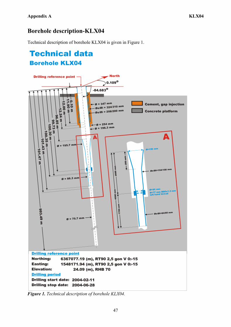
Borehole description-KLX04 Technical description of borehole KLX04 is given in Figure 1. Technical dataBorehole KLX04
6367077.19 (m),1548171.94 (m), 24.09 (m),
2004-02-11 2004-06-28
RT90 2,5 gon V 0:-15 RT90 2,5 gon V 0:-15 RHB 70
Northing:Easting:Elevation:
Drilling start date:Drilling stop date:
Drilling reference point
Drilling period
North
0.109o
-84.683o
Drilling reference point
Cement, gap injection
Concrete platform
11.90 m
Ø = 196.3 mm
Øo/ = 324/310 mmØi
Øo/ = 208/200 mmØi
Ø = 75.7 mm
A
0.10 m
Ø = 86.3 mm
12.24 m
100. 30 m
12.00 m
96 .85 m
101. 47 m
100 .35 m
993.49 m
Ø = 347 mm
Ø = 254 mm
Ø = 195.7 mm
101.43 m
99 .73 m
Ø=195 mm
Øo/ =104/100 mmØi
Ø=84 mm
Ø=77 mm M80x1.5 mm
left hand thread
Øo/ =84/80 mmØi
300
mm
2880
mm
4580
mm
1700
mm
A
Figure 1. Technical description of borehole KLX04.
Appendix A KLX04
48
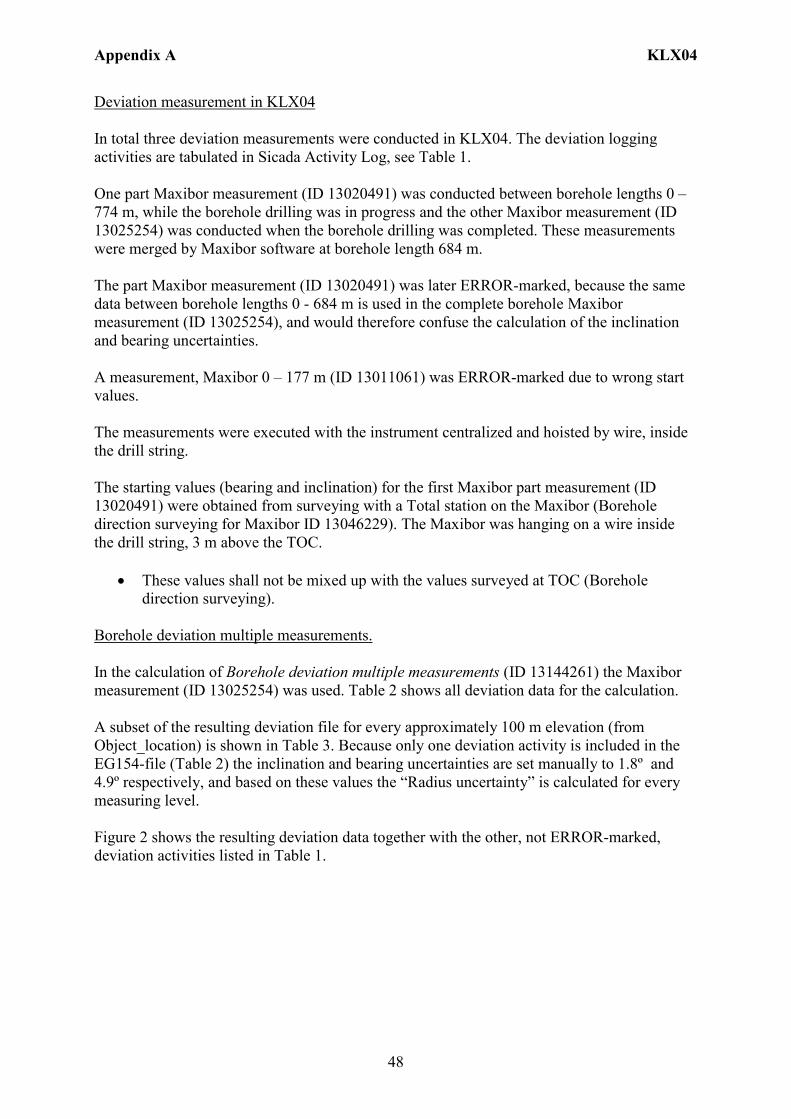
Deviation measurement in KLX04 In total three deviation measurements were conducted in KLX04. The deviation logging activities are tabulated in Sicada Activity Log, see Table 1. One part Maxibor measurement (ID 13020491) was conducted between borehole lengths 0 – 774 m, while the borehole drilling was in progress and the other Maxibor measurement (ID 13025254) was conducted when the borehole drilling was completed. These measurements were merged by Maxibor software at borehole length 684 m. The part Maxibor measurement (ID 13020491) was later ERROR-marked, because the same data between borehole lengths 0 - 684 m is used in the complete borehole Maxibor measurement (ID 13025254), and would therefore confuse the calculation of the inclination and bearing uncertainties. A measurement, Maxibor 0 – 177 m (ID 13011061) was ERROR-marked due to wrong start values. The measurements were executed with the instrument centralized and hoisted by wire, inside the drill string. The starting values (bearing and inclination) for the first Maxibor part measurement (ID 13020491) were obtained from surveying with a Total station on the Maxibor (Borehole direction surveying for Maxibor ID 13046229). The Maxibor was hanging on a wire inside the drill string, 3 m above the TOC.
• These values shall not be mixed up with the values surveyed at TOC (Borehole direction surveying).
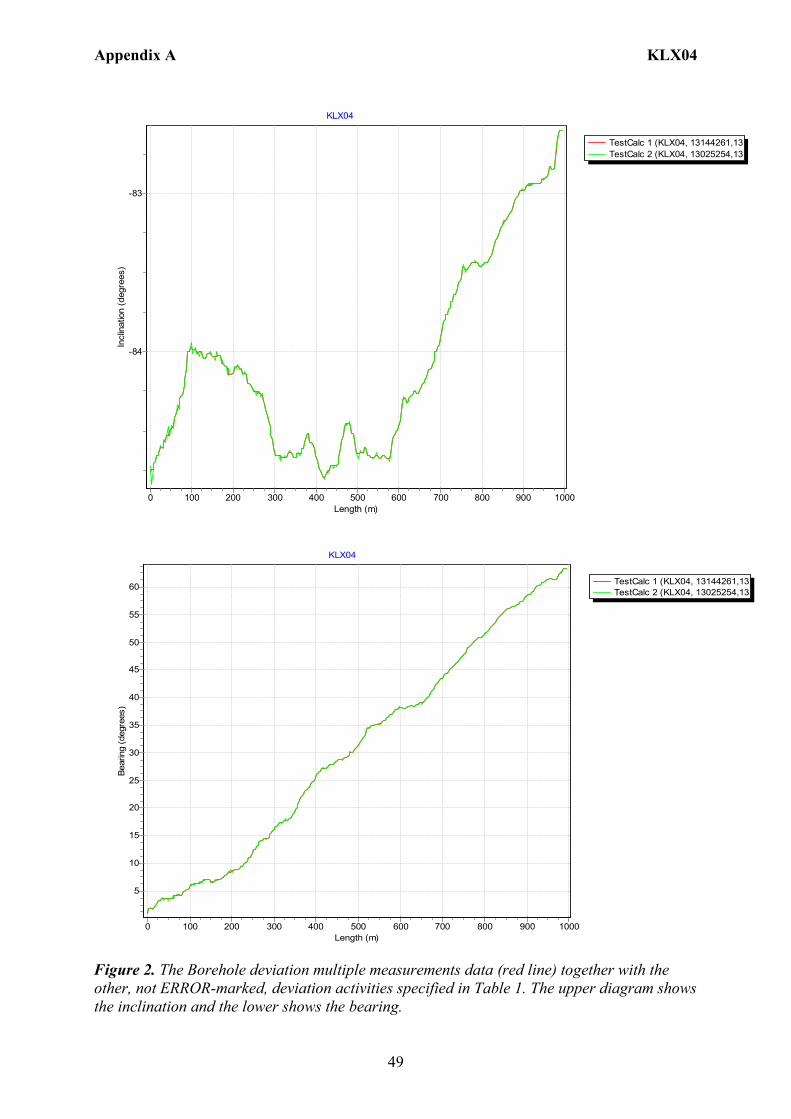
Borehole deviation multiple measurements. In the calculation of Borehole deviation multiple measurements (ID 13144261) the Maxibor measurement (ID 13025254) was used. Table 2 shows all deviation data for the calculation. A subset of the resulting deviation file for every approximately 100 m elevation (from Object_location) is shown in Table 3. Because only one deviation activity is included in the EG154-file (Table 2) the inclination and bearing uncertainties are set manually to 1.8º and 4.9º respectively, and based on these values the “Radius uncertainty” is calculated for every measuring level. Figure 2 shows the resulting deviation data together with the other, not ERROR-marked, deviation activities listed in Table 1.
Appendix A KLX04
49
TestCalc 1 (KLX04, 13144261,13TestCalc 2 (KLX04, 13025254,13
KLX04
Length (m)10009008007006005004003002001000
Incl
inat
ion
(deg
rees
)
-83
-84
TestCalc 1 (KLX04, 13144261,13TestCalc 2 (KLX04, 13025254,13
KLX04
Length (m)10009008007006005004003002001000
Bear
ing
(deg
rees
)
60
55
50
45
40
35
30
25
20
15
10
5
Figure 2. The Borehole deviation multiple measurements data (red line) together with the other, not ERROR-marked, deviation activities specified in Table 1. The upper diagram shows the inclination and the lower shows the bearing.
Appendix A KLX04
50
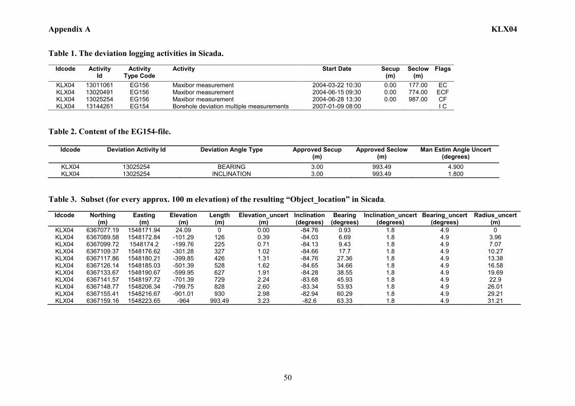
Table 1. The deviation logging activities in Sicada.
Idcode Activity Id
Activity Type Code
Activity Start Date Secup (m)
Seclow(m)
Flags
KLX04 13011061 EG156 Maxibor measurement 2004-03-22 10:30 0.00 177.00 EC KLX04 13020491 EG156 Maxibor measurement 2004-06-15 09:30 0.00 774.00 ECF KLX04 13025254 EG156 Maxibor measurement 2004-06-28 13:30 0.00 987.00 CF KLX04 13144261 EG154 Borehole deviation multiple measurements 2007-01-09 08:00 I C
Table 2. Content of the EG154-file.
Idcode Deviation Activity Id Deviation Angle Type Approved Secup (m)
Approved Seclow (m)
Man Estim Angle Uncert (degrees)
KLX04 13025254 BEARING 3.00 993.49 4.900 KLX04 13025254 INCLINATION 3.00 993.49 1.800
Table 3. Subset (for every approx. 100 m elevation) of the resulting “Object_location” in Sicada.
Idcode
Northing (m)
Easting (m)
Elevation (m)
Length (m)
Elevation_uncert(m)
Inclination (degrees)
Bearing (degrees)
Inclination_uncert(degrees)
Bearing_uncert(degrees)
Radius_uncert (m)
KLX04 6367077.19 1548171.94 24.09 0 0.00 -84.76 0.93 1.8 4.9 0 KLX04 6367089.58 1548172.84 -101.29 126 0.39 -84.03 6.69 1.8 4.9 3.96 KLX04 6367099.72 1548174.2 -199.76 225 0.71 -84.13 9.43 1.8 4.9 7.07 KLX04 6367109.37 1548176.62 -301.28 327 1.02 -84.66 17.7 1.8 4.9 10.27 KLX04 6367117.86 1548180.21 -399.85 426 1.31 -84.76 27.36 1.8 4.9 13.38 KLX04 6367126.14 1548185.03 -501.39 528 1.62 -84.65 34.66 1.8 4.9 16.58 KLX04 6367133.67 1548190.67 -599.95 627 1.91 -84.28 38.55 1.8 4.9 19.69 KLX04 6367141.57 1548197.72 -701.39 729 2.24 -83.68 45.93 1.8 4.9 22.9 KLX04 6367148.77 1548206.34 -799.75 828 2.60 -83.34 53.93 1.8 4.9 26.01 KLX04 6367155.41 1548216.67 -901.01 930 2.98 -82.94 60.29 1.8 4.9 29.21 KLX04 6367159.16 1548223.65 -964 993.49 3.23 -82.6 63.33 1.8 4.9 31.21
Appendix A KLX05
51
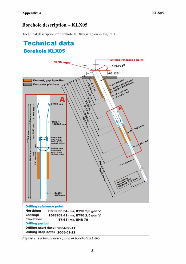
Borehole description – KLX05 Technical description of borehole KLX05 is given in Figure 1. Technical dataBorehole KLX05
6365633.34 (m),1548909.41 (m), 17.63 (m),
2004-08-11 2005-01-22
RT90 2,5 gon V RHB 70
RT90 2,5 gon VNorthing:Easting:Elevation:
Drilling start date:Drilling stop date:
Drilling reference point
Drilling period
Cement, gap injectionConcrete platform
North189.721o
-65.120o
Drilling reference point
Ø = 195.0 mm
Øo/= 323/310 mm
Øi
Øo/= 208/200 mm
Øi
Ø = 75.8 mm
A
0.10 m15.00 m
75.10 m12.60 m
70.95 m
100.30 m
996.81 mØ = 343 mm
Ø = 250 mm
108.01 m73.96 m
1000.16 m
Abandoned
Reaming Tool
Øo/ =60.0/75.8
Øi
mm
Ø = 86.0 mm
Ø = 162.3 mm
Ø=195 mm
Øo/ =104/100 mm
Øi
Ø=84 mmØ=77 mm M80x1.5 mm left hand thread
Øo/ =84/80 mm
Øi
300
mm
301 0
mm
3706
0 m
m34
050
mm
A
Ø=194 mmØ=89 mm M92x2.5 mm left hand thread
1140
mm
230
mm
Figure 1. Technical description of borehole KLX05
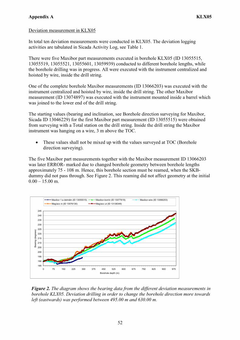
Appendix A KLX05
52
Deviation measurement in KLX05 In total ten deviation measurements were conducted in KLX05. The deviation logging activities are tabulated in Sicada Activity Log, see Table 1. There were five Maxibor part measurements executed in borehole KLX05 (ID 13055515, 13055519, 13055521, 13055601, 13059939) conducted to different borehole lengths, while the borehole drilling was in progress. All were executed with the instrument centralized and hoisted by wire, inside the drill string. One of the complete borehole Maxibor measurements (ID 13066203) was executed with the instrument centralized and hoisted by wire, inside the drill string. The other Maxibor measurement (ID 13074897) was executed with the instrument mounted inside a barrel which was joined to the lower end of the drill string. The starting values (bearing and inclination, see Borehole direction surveying for Maxibor, Sicada ID 13046229) for the first Maxibor part measurement (ID 13055515) were obtained from surveying with a Total station on the drill string. Inside the drill string the Maxibor instrument was hanging on a wire, 3 m above the TOC.
• These values shall not be mixed up with the values surveyed at TOC (Borehole direction surveying).
The five Maxibor part measurements together with the Maxibor measurement ID 13066203 was later ERROR- marked due to changed borehole geometry between borehole lengths approximately 75 - 108 m. Hence, this borehole section must be reamed, when the SKB-dummy did not pass through. See Figure 2. This reaming did not affect geometry at the initial 0.00 – 15.00 m.
185
190
195
200
205
210
215
220
225
230
235
240
245
0 75 150 225 300 375 450 525 600 675 750 825 900 975
Borehole depth (m)
Bea
ring
(deg
rees
)
Maxibor 1:a delmätn (ID 13055515) Maxibor-borrör (ID 13077619) Maxibor-wire (ID 13066203)
Mag/acc in (ID 13076130) Mag/acc ut (ID 13138349)
Figure 2. The diagram shows the bearing data from the different deviation measurements in borehole KLX05. Deviation drilling in order to change the borehole direction more towards left (eastwards) was performed between 495.00 m and 630.00 m.
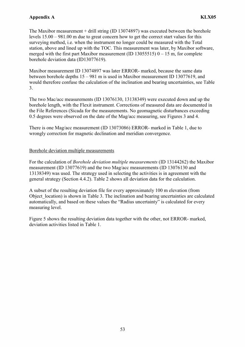
Appendix A KLX05
53
The Maxibor measurement + drill string (ID 13074897) was executed between the borehole levels 15.00 – 981.00 m due to great concern how to get the correct start values for this surveying method, i.e. when the instrument no longer could be measured with the Total station, above and lined up with the TOC. This measurement was later, by Maxibor software, merged with the first part Maxibor measurement (ID 13055515) 0 – 15 m, for complete borehole deviation data (ID13077619). Maxibor measurement ID 13074897 was later ERROR- marked, because the same data between borehole depths 15 – 981 m is used in Maxibor measurement ID 13077619, and would therefore confuse the calculation of the inclination and bearing uncertainties, see Table 3. The two Mac/acc measurements (ID 13076130, 13138349) were executed down and up the borehole length, with the Flexit instrument. Corrections of measured data are documented in the File References (Sicada for the measurements. No geomagnetic disturbances exceeding 0.5 degrees were observed on the date of the Mag/acc measuring, see Figures 3 and 4. There is one Mag/acc measurement (ID 13073086) ERROR- marked in Table 1, due to wrongly correction for magnetic declination and meridian convergence. Borehole deviation multiple measurements For the calculation of Borehole deviation multiple measurements (ID 13144262) the Maxibor measurement (ID 13077619) and the two Mag/acc measurements (ID 13076130 and 13138349) was used. The strategy used in selecting the activities is in agreement with the general strategy (Section 4.4.2). Table 2 shows all deviation data for the calculation. A subset of the resulting deviation file for every approximately 100 m elevation (from Object_location) is shown in Table 3. The inclination and bearing uncertainties are calculated automatically, and based on these values the “Radius uncertainty” is calculated for every measuring level. Figure 5 shows the resulting deviation data together with the other, not ERROR- marked, deviation activities listed in Table 1.

Appendix A KLX05
54
Figure 3. The geomagnetic field was observed at the Observatory in Uppsala on 2005-05-19.
Figure 4. The geomagnetic field was observed at the Observatory in Uppsala on 2005-05-20.
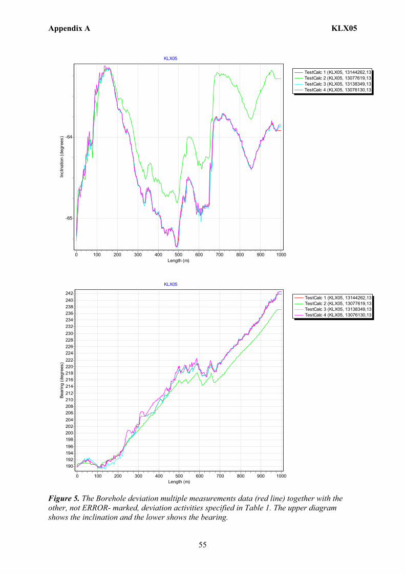
Appendix A KLX05
55
TestCalc 1 (KLX05, 13144262,13TestCalc 2 (KLX05, 13077619,13TestCalc 3 (KLX05, 13138349,13TestCalc 4 (KLX05, 13076130,13
KLX05
Length (m)10009008007006005004003002001000
Incl
inat
ion
(deg
rees
) -64
-65
TestCalc 1 (KLX05, 13144262,13TestCalc 2 (KLX05, 13077619,13TestCalc 3 (KLX05, 13138349,13TestCalc 4 (KLX05, 13076130,13
KLX05
Length (m)10009008007006005004003002001000
Bear
ing
(deg
rees
)
242240238236234232230228226224222220218216214212210208206204202200198196194192190
Figure 5. The Borehole deviation multiple measurements data (red line) together with the other, not ERROR- marked, deviation activities specified in Table 1. The upper diagram shows the inclination and the lower shows the bearing.
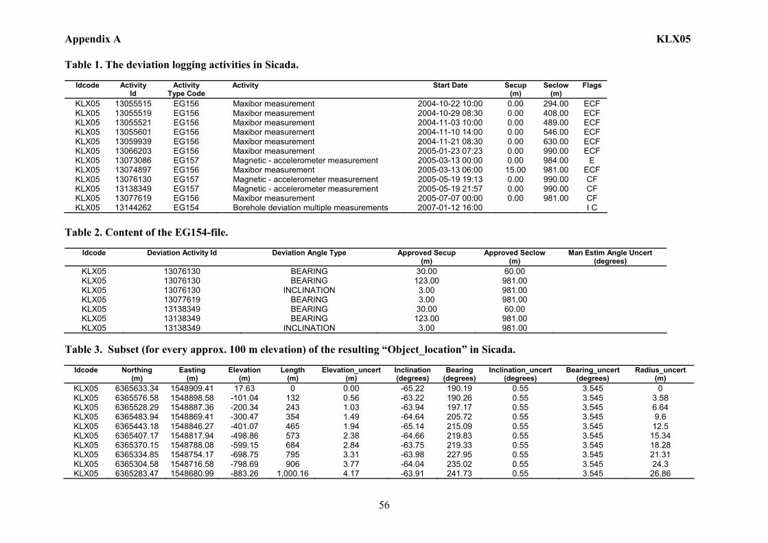
Appendix A KLX05
56
Table 1. The deviation logging activities in Sicada.
Idcode Activity Id
Activity Type Code
Activity Start Date Secup (m)
Seclow (m)
Flags
KLX05 13055515 EG156 Maxibor measurement 2004-10-22 10:00 0.00 294.00 ECF KLX05 13055519 EG156 Maxibor measurement 2004-10-29 08:30 0.00 408.00 ECF KLX05 13055521 EG156 Maxibor measurement 2004-11-03 10:00 0.00 489.00 ECF KLX05 13055601 EG156 Maxibor measurement 2004-11-10 14:00 0.00 546.00 ECF KLX05 13059939 EG156 Maxibor measurement 2004-11-21 08:30 0.00 630.00 ECF KLX05 13066203 EG156 Maxibor measurement 2005-01-23 07:23 0.00 990.00 ECF KLX05 13073086 EG157 Magnetic - accelerometer measurement 2005-03-13 00:00 0.00 984.00 E KLX05 13074897 EG156 Maxibor measurement 2005-03-13 06:00 15.00 981.00 ECF KLX05 13076130 EG157 Magnetic - accelerometer measurement 2005-05-19 19:13 0.00 990.00 CF KLX05 13138349 EG157 Magnetic - accelerometer measurement 2005-05-19 21:57 0.00 990.00 CF KLX05 13077619 EG156 Maxibor measurement 2005-07-07 00:00 0.00 981.00 CF KLX05 13144262 EG154 Borehole deviation multiple measurements 2007-01-12 16:00 I C
Table 2. Content of the EG154-file.
Idcode Deviation Activity Id Deviation Angle Type Approved Secup
(m) Approved Seclow
(m) Man Estim Angle Uncert
(degrees) KLX05 13076130 BEARING 30.00 60.00 KLX05 13076130 BEARING 123.00 981.00 KLX05 13076130 INCLINATION 3.00 981.00 KLX05 13077619 BEARING 3.00 981.00 KLX05 13138349 BEARING 30.00 60.00 KLX05 13138349 BEARING 123.00 981.00 KLX05 13138349 INCLINATION 3.00 981.00
Table 3. Subset (for every approx. 100 m elevation) of the resulting “Object_location” in Sicada.
Idcode
Northing
(m) Easting
(m) Elevation
(m) Length
(m) Elevation_uncert
(m) Inclination (degrees)
Bearing (degrees)
Inclination_uncert (degrees)
Bearing_uncert (degrees)
Radius_uncert (m)
KLX05 6365633.34 1548909.41 17.63 0 0.00 -65.22 190.19 0.55 3.545 0 KLX05 6365576.58 1548898.58 -101.04 132 0.56 -63.22 190.26 0.55 3.545 3.58 KLX05 6365528.29 1548887.36 -200.34 243 1.03 -63.94 197.17 0.55 3.545 6.64 KLX05 6365483.94 1548869.41 -300.47 354 1.49 -64.64 205.72 0.55 3.545 9.6 KLX05 6365443.18 1548846.27 -401.07 465 1.94 -65.14 215.09 0.55 3.545 12.5 KLX05 6365407.17 1548817.94 -498.86 573 2.38 -64.66 219.83 0.55 3.545 15.34 KLX05 6365370.15 1548788.08 -599.15 684 2.84 -63.75 219.33 0.55 3.545 18.28 KLX05 6365334.85 1548754.17 -698.75 795 3.31 -63.98 227.95 0.55 3.545 21.31 KLX05 6365304.58 1548716.58 -798.69 906 3.77 -64.04 235.02 0.55 3.545 24.3 KLX05 6365283.47 1548680.99 -883.26 1,000.16 4.17 -63.91 241.73 0.55 3.545 26.86
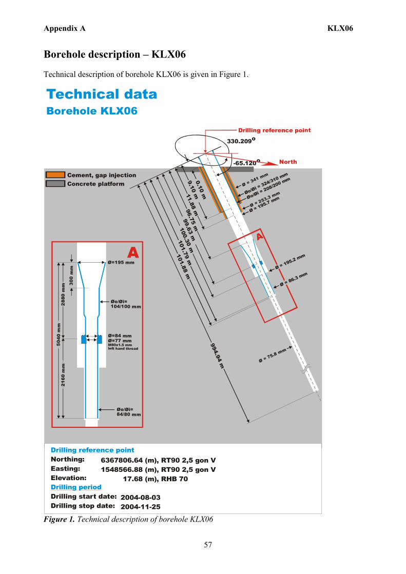
Appendix A KLX06
57
Borehole description – KLX06 Technical description of borehole KLX06 is given in Figure 1. Technical dataBorehole KLX06
6367806.64 (m),1548566.88 (m), 17.68 (m),
2004-08-03 2004-11-25
RT90 2,5 gon V RHB 70
RT90 2,5 gon VNorthing:Easting:Elevation:
Drilling start date:Drilling stop date:
Drilling reference point
Drilling period
Cement, gap injectionConcrete platform
Ø=195 mm
Øo/ =104/100 mm
Øi
Ø=84 mmØ=77 mm M80x1.5 mm left hand thread
Øo/ =84/80 mm
Øi
288
0 m
m50
40 m
m21
60 m
m
A
300
mm
North-65.120o
330.209oDrilling reference point
Ø = 195.7 mmØo/
= 324/310 mm
Øi
Øo/= 208/200 mm
Øi
Ø = 75.8 mm
A
0.10 m11.88 m
100.30 m9.10 m
96.75 m
101.79 m
101.88 m
Ø = 341 mm
Ø = 253.3 mm994.94 m
99.63 m
Ø = 86.3 mmØ = 195.2 mm
Figure 1. Technical description of borehole KLX06
Appendix A KLX06
58
Deviation measurement in KLX06 In total six deviation measurements are conducted in KLX06. The deviation logging activities are tabulated in Sicada Activity Log, see Table 1. There are four Maxibor part measurements executed and merged in borehole KLX06 to create a complete borehole deviation measurement. All measurements were executed with the instrument centralized and hoisted by wire, inside the drill string. The starting values (bearing and inclination, see Borehole direction surveying for Maxibor, Sicada ID 13030829) for the first Maxibor part measurement (ID 13032423) were obtained from surveying with a Total station on the drill string. Inside the drill string was the Maxibor instrument hanging on a wire, 3 m above the TOC.
• These values shall not be mixed up with the values surveyed at TOC (Borehole direction surveying).
The first Maxibor part measurement is (ID13032423) between borehole lengths 0 – 222 m. The second part measurement is measured between borehole lengths 204 – 390 m and then merged by Maxibor software (at borehole lengths 204 m) with the first part measurement to create measurement (ID 13034800) 0 – 390 m. The third part measurement is measured between borehole lengths 372 – 735 m and then merged by Maxibor software (at borehole lengths 372 m) with the second part measurement to create measurement (ID 13055618) 0 – 735 m. The fourth part measurement is measured between borehole lengths 702 – 987 m and then merged by Maxibor software (at borehole lengths 702 m) with the third part measurement to create the complete borehole measurement (ID 13062810) 0 – 987 m. This complete borehole Maxibor measurement (ID 13062810) was wrongly bug reported and ERROR- marked, when it was noticed that the values at borehole length 0.00 m did not match the values at TOC from Borehole direction surveying (ID 13030518). These initial values was then wrongly changed and the following calculation created the Maxibor measurement (ID 13131495) which also had to be ERROR- marked when the mistake was discovered. The correct complete borehole Maxibor measurement in KLX06 has ID 1318717. The first, second and third part measurements was later ERROR- marked because those data is involved in the fourth measurement and would therefore interfere the calculation of the inclination and bearing uncertainties. The two Mac/acc measurements (ID 13117554, 13138707) were executed down and up the borehole length, with the Flexit instrument. Corrections of measured data are documented in the File References (Sicada) for the measurements. No geomagnetic disturbances exceeding 0.5 degrees were observed on the date of the Mag/acc measuring, see Figure 2. There is two ERROR- marked Mag/acc measurements (ID 13073342 and 13114637) in Table 1, due to wrongly correction for magnetic declination and meridian convergence.
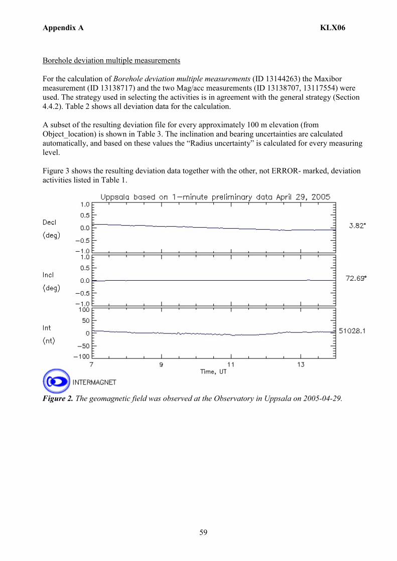
Appendix A KLX06
59
Borehole deviation multiple measurements For the calculation of Borehole deviation multiple measurements (ID 13144263) the Maxibor measurement (ID 13138717) and the two Mag/acc measurements (ID 13138707, 13117554) were used. The strategy used in selecting the activities is in agreement with the general strategy (Section 4.4.2). Table 2 shows all deviation data for the calculation. A subset of the resulting deviation file for every approximately 100 m elevation (from Object_location) is shown in Table 3. The inclination and bearing uncertainties are calculated automatically, and based on these values the “Radius uncertainty” is calculated for every measuring level. Figure 3 shows the resulting deviation data together with the other, not ERROR- marked, deviation activities listed in Table 1.
Figure 2. The geomagnetic field was observed at the Observatory in Uppsala on 2005-04-29.
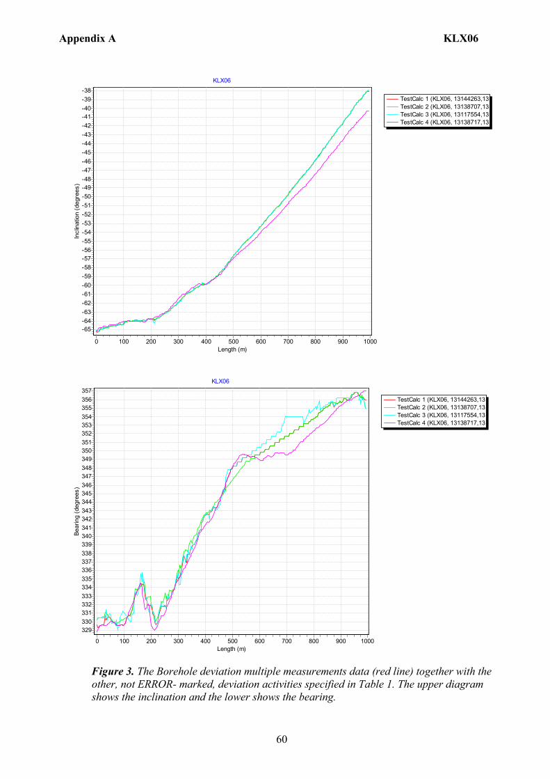
Appendix A KLX06
60
TestCalc 1 (KLX06, 13144263,13TestCalc 2 (KLX06, 13138707,13TestCalc 3 (KLX06, 13117554,13TestCalc 4 (KLX06, 13138717,13
KLX06
Length (m)10009008007006005004003002001000
Incl
inat
ion
(deg
rees
)
-38-39-40-41-42-43-44-45-46-47-48-49-50-51-52-53-54-55-56-57-58-59-60-61-62-63-64-65
TestCalc 1 (KLX06, 13144263,13TestCalc 2 (KLX06, 13138707,13TestCalc 3 (KLX06, 13117554,13TestCalc 4 (KLX06, 13138717,13
KLX06
Length (m)10009008007006005004003002001000
Bear
ing
(deg
rees
)
357356355354353352351350349348347346345344343342341340339338337336335334333332331330329
Figure 3. The Borehole deviation multiple measurements data (red line) together with the other, not ERROR- marked, deviation activities specified in Table 1. The upper diagram shows the inclination and the lower shows the bearing.
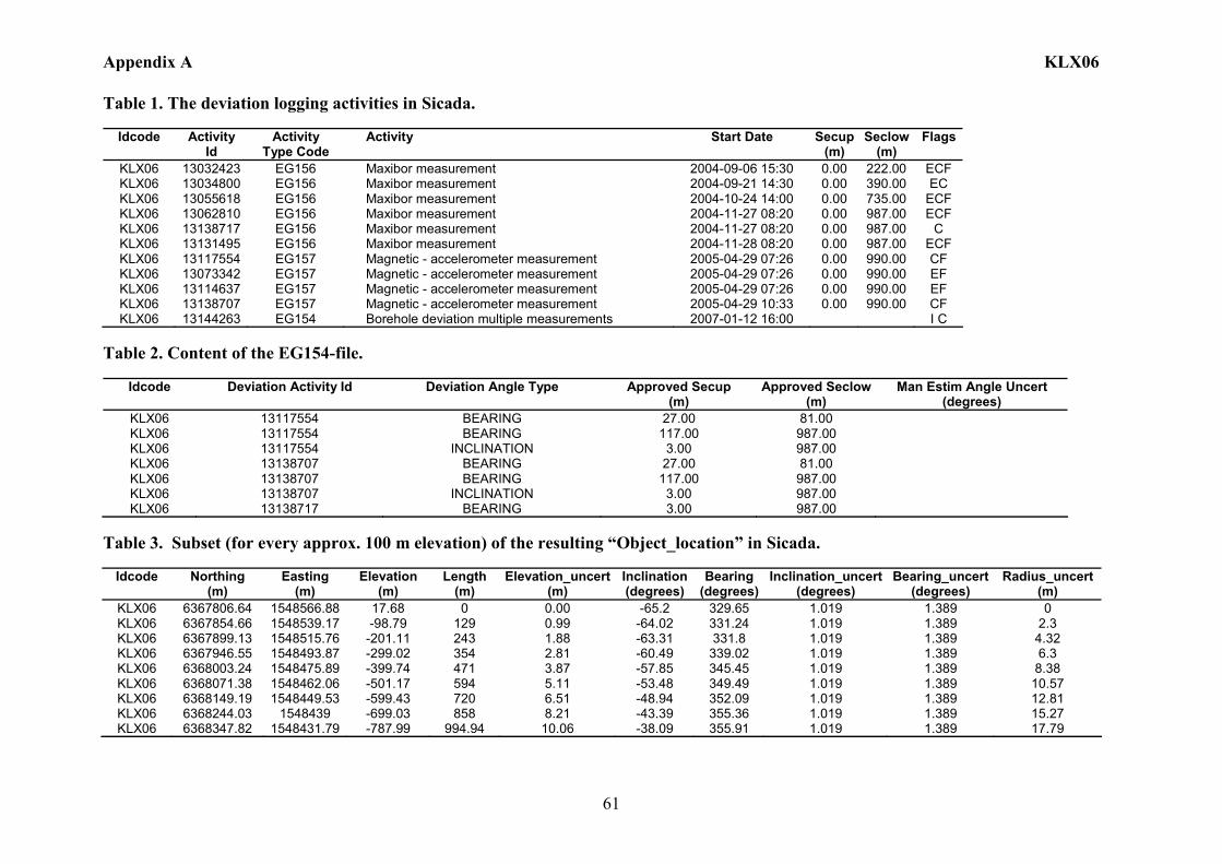
Appendix A KLX06
61
Table 1. The deviation logging activities in Sicada.
Idcode Activity Id
Activity Type Code
Activity Start Date Secup(m)
Seclow(m)
Flags
KLX06 13032423 EG156 Maxibor measurement 2004-09-06 15:30 0.00 222.00 ECF KLX06 13034800 EG156 Maxibor measurement 2004-09-21 14:30 0.00 390.00 EC KLX06 13055618 EG156 Maxibor measurement 2004-10-24 14:00 0.00 735.00 ECF KLX06 13062810 EG156 Maxibor measurement 2004-11-27 08:20 0.00 987.00 ECF KLX06 13138717 EG156 Maxibor measurement 2004-11-27 08:20 0.00 987.00 C KLX06 13131495 EG156 Maxibor measurement 2004-11-28 08:20 0.00 987.00 ECF KLX06 13117554 EG157 Magnetic - accelerometer measurement 2005-04-29 07:26 0.00 990.00 CF KLX06 13073342 EG157 Magnetic - accelerometer measurement 2005-04-29 07:26 0.00 990.00 EF KLX06 13114637 EG157 Magnetic - accelerometer measurement 2005-04-29 07:26 0.00 990.00 EF KLX06 13138707 EG157 Magnetic - accelerometer measurement 2005-04-29 10:33 0.00 990.00 CF KLX06 13144263 EG154 Borehole deviation multiple measurements 2007-01-12 16:00 I C
Table 2. Content of the EG154-file.
Idcode Deviation Activity Id Deviation Angle Type Approved Secup
(m) Approved Seclow
(m) Man Estim Angle Uncert
(degrees) KLX06 13117554 BEARING 27.00 81.00 KLX06 13117554 BEARING 117.00 987.00 KLX06 13117554 INCLINATION 3.00 987.00 KLX06 13138707 BEARING 27.00 81.00 KLX06 13138707 BEARING 117.00 987.00 KLX06 13138707 INCLINATION 3.00 987.00 KLX06 13138717 BEARING 3.00 987.00
Table 3. Subset (for every approx. 100 m elevation) of the resulting “Object_location” in Sicada.
Idcode
Northing
(m) Easting
(m) Elevation
(m) Length
(m) Elevation_uncert
(m) Inclination (degrees)
Bearing (degrees)
Inclination_uncert(degrees)
Bearing_uncert(degrees)
Radius_uncert (m)
KLX06 6367806.64 1548566.88 17.68 0 0.00 -65.2 329.65 1.019 1.389 0 KLX06 6367854.66 1548539.17 -98.79 129 0.99 -64.02 331.24 1.019 1.389 2.3 KLX06 6367899.13 1548515.76 -201.11 243 1.88 -63.31 331.8 1.019 1.389 4.32 KLX06 6367946.55 1548493.87 -299.02 354 2.81 -60.49 339.02 1.019 1.389 6.3 KLX06 6368003.24 1548475.89 -399.74 471 3.87 -57.85 345.45 1.019 1.389 8.38 KLX06 6368071.38 1548462.06 -501.17 594 5.11 -53.48 349.49 1.019 1.389 10.57 KLX06 6368149.19 1548449.53 -599.43 720 6.51 -48.94 352.09 1.019 1.389 12.81 KLX06 6368244.03 1548439 -699.03 858 8.21 -43.39 355.36 1.019 1.389 15.27 KLX06 6368347.82 1548431.79 -787.99 994.94 10.06 -38.09 355.91 1.019 1.389 17.79
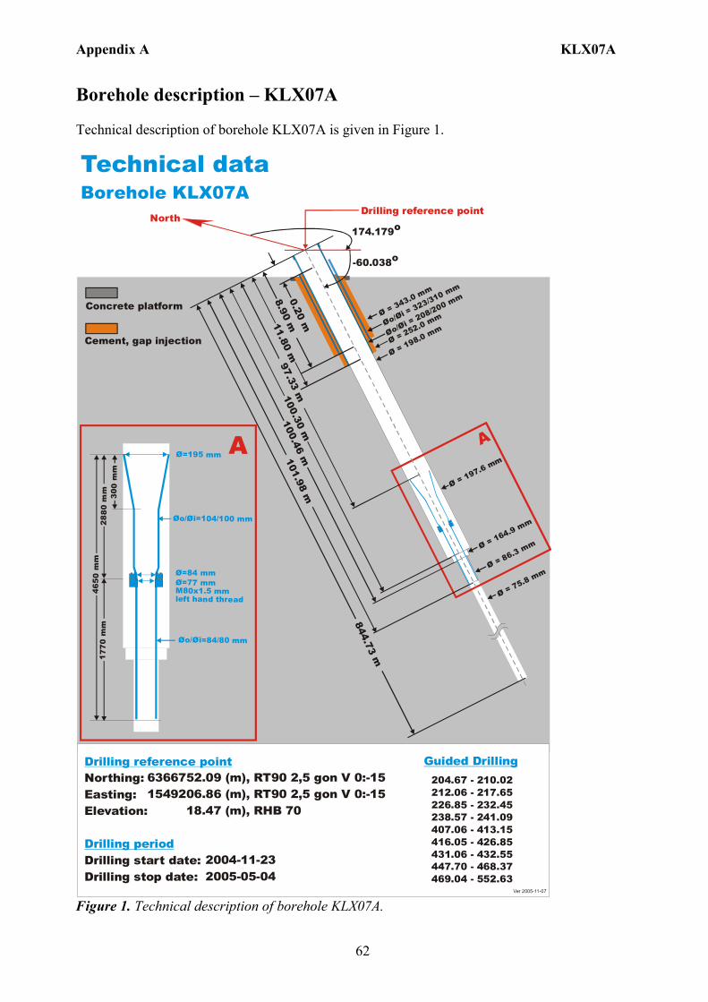
Appendix A KLX07A
62
Borehole description – KLX07A Technical description of borehole KLX07A is given in Figure 1. Technical dataBorehole KLX07A
6366752.09 (m),1549206.86 (m), 18.47 (m),
2004-11-23 2005-05-04
RT90 2,5 gon V 0:-15 RHB 70
RT90 2,5 gon V 0:-15Northing:Easting:Elevation:
Drilling start date:Drilling stop date:
Drilling reference point
Drilling period
North174.179o
-60.038o
Drilling reference point
Cement, gap injection
Concrete platform
204.67 - 210.02212.06 - 217.65226.85 - 232.45238.57 - 241.09407.06 - 413.15416.05 - 426.85431.06 - 432.55447.70 - 468.37469.04 - 552.63
Guided Drilling
Ø = 198.0 mmØo/
= 323/310 mm
Øi
Øo/= 208/200 mm
Øi
Ø = 75.8 mm
A
0.20 m11.80 m8.90 m
100.30 m101.98 m
Ø = 343.0 mm
Ø = 252.0 mm
Ø = 197.6 mm
100.46 m
97.33 m
844.73 m
Ø = 164.9 mm
Ø = 86.3 mm
Ø=195 mm
Øo/ =104/100 mmØi
Ø=84 mmØ=77 mm M80x1.5 mm left hand thread
Øo/ =84/80 mmØi
300
mm
2880
mm
465 0
mm
1 770
mm
A
Ver 2005-11-07 Figure 1. Technical description of borehole KLX07A.

Appendix A KLX07A
63
Deviation measurement in KLX07A In total seven deviation measurements were conducted in KLX07A. The deviation logging activities are tabulated in Sicada Activity Log, see Table 1. All Maxibor measurements were executed with the instrument mounted inside a barrel which was joined to the lower end of the drill string. The starting values for the Maxibor measurements in KLX07A was measured with the Total station aiming on a prism, above and lined up with the TOC. A later calculation gave the values at borehole length 3.00 m which was used as start values (bearing and inclination) for the Maxibor measurements. When the calculation of the Maxibor measurement was done, the values were added for borehole length 0.00 m. See document (ID 1037594 Documentum). There are two Maxibor part measurements executed in borehole KLX07A. Measurment (ID 13062912) between borehole lengths 0 – 402 m was ERROR- marked due to wrong values at 0.00 m. Measurement (ID 13064857) between borehole lengths 390 – 429 m was ERROR- marked due to problem with the instrument. One of the two complete borehole Maxibor measurements (ID 13073321) was ERROR- marked due to missing data at borehole length 0.00 m. These data (from Borehole surveying at TOC) were added to the Maxibor raw data for a complete borehole measurement (ID 13078348) The two correct Maxibor measurements (ID 13078348, 13138798) were executed down and up the borehole length. The two Mac/acc measurements (ID 13120699, 13138780) were executed down and up the borehole length, with the Flexit instrument. Corrections of measured data are documented in the File References (Sicada) for the measurements. No geomagnetic disturbances exceeding 0.5 degrees were observed on the date of the Mag/acc measurement, see Figure 2. There is one ERROR- marked Mag/acc measurements (ID 13073418) due to wrong calculation of the deviation. Borehole deviation multiple measurements For the calculation of Borehole deviation multiple measurements (ID 13144264) the two Maxibor measurements (ID 13078348 and 13138798) and the two Mag/acc measurements (ID 13120699 and 13138780) were used. The strategy used in selecting the activities is in agreement with the general strategy (Section 4.4.2). Table 2 shows all deviation data for the calculation. A subset of the resulting deviation file for every approximately 100 m elevation (from Object_location) is shown in Table 3. The inclination and bearing uncertainties were calculated automatically, and based on these values the “Radius uncertainty” was calculated for every measuring level. Figure 3 shows the resulting deviation data together with the other, not ERROR- marked, deviation activities listed in Table 1.
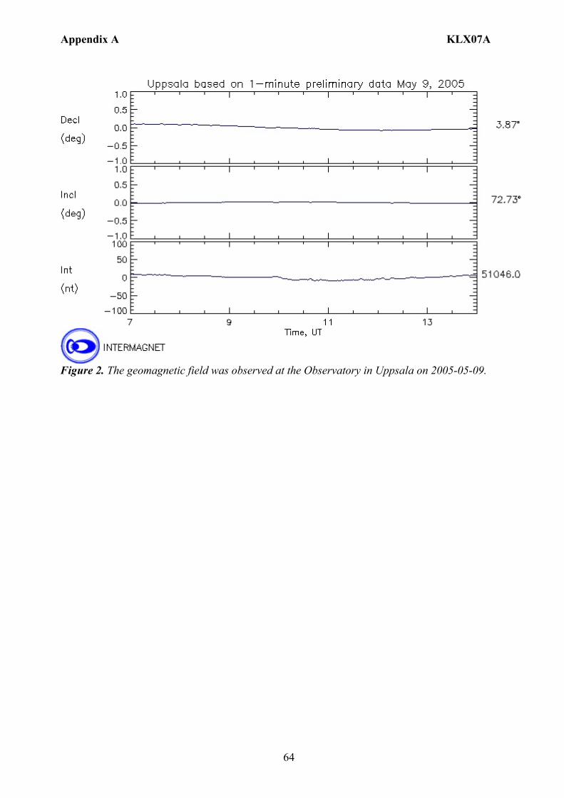
Appendix A KLX07A
64
Figure 2. The geomagnetic field was observed at the Observatory in Uppsala on 2005-05-09.

Appendix A KLX07A
65
TestCalc 1 (KLX07A, 13144264,1TestCalc 2 (KLX07A, 13138798,1TestCalc 3 (KLX07A, 13078348,1TestCalc 4 (KLX07A, 13138780,1TestCalc 5 (KLX07A, 13120699,1
KLX07A
Length (m)8006004002000
Incl
inat
ion
(deg
rees
)
-44-45-46-47-48-49-50-51-52-53-54-55-56-57-58-59-60
TestCalc 1 (KLX07A, 13144264,1TestCalc 2 (KLX07A, 13138798,1TestCalc 3 (KLX07A, 13078348,1TestCalc 4 (KLX07A, 13138780,1TestCalc 5 (KLX07A, 13120699,1
KLX07A
Length (m)8006004002000
Bear
ing
(deg
rees
)
181
180
179
178
177
176
175
174
173
172
171
170
169
168
Figure 3. The Borehole deviation multiple measurements data (red line) together with the other, not ERROR- marked, deviation activities) specified in Table 1. The upper diagram shows the inclination and the lower shows the bearing.
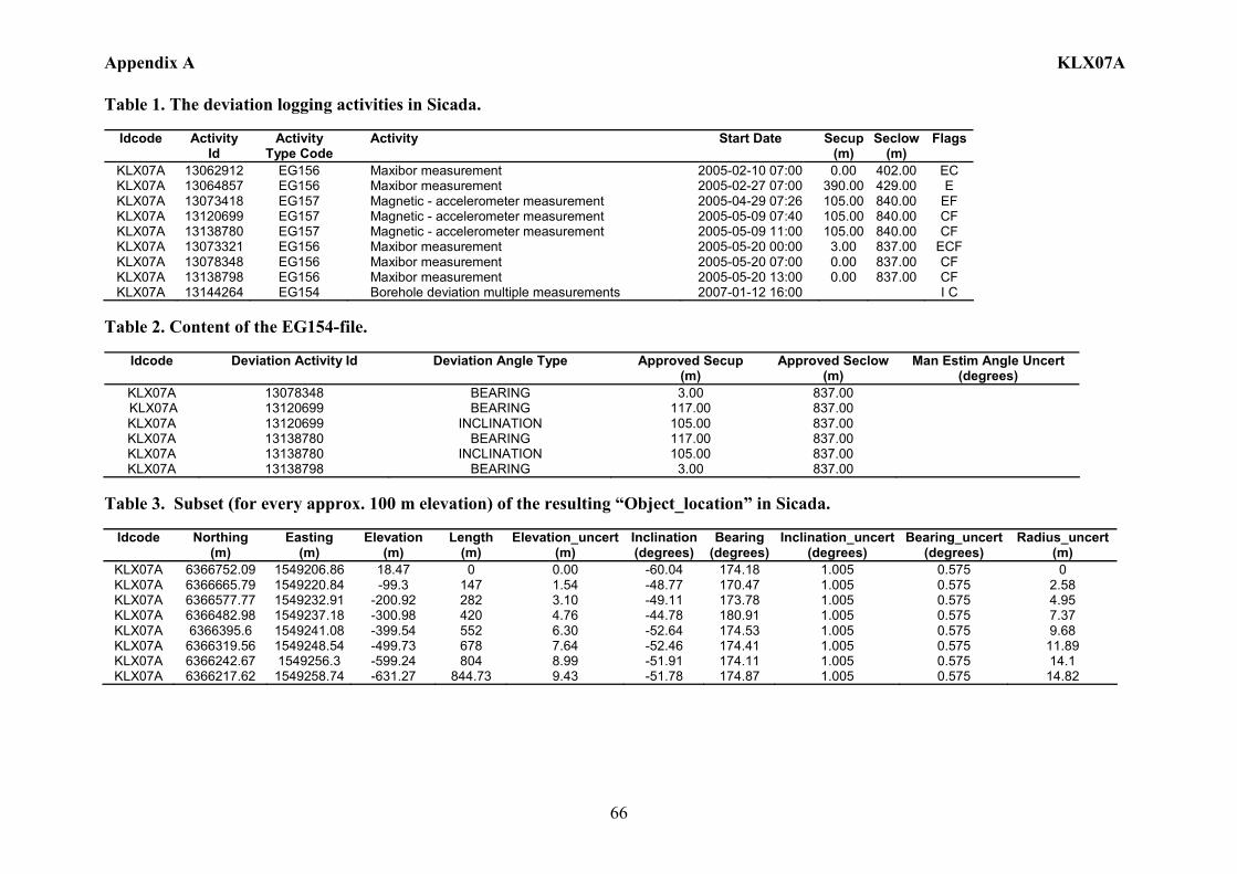
Appendix A KLX07A
66
Table 1. The deviation logging activities in Sicada.
Idcode Activity Id
Activity Type Code
Activity Start Date Secup(m)
Seclow(m)
Flags
KLX07A 13062912 EG156 Maxibor measurement 2005-02-10 07:00 0.00 402.00 EC KLX07A 13064857 EG156 Maxibor measurement 2005-02-27 07:00 390.00 429.00 E KLX07A 13073418 EG157 Magnetic - accelerometer measurement 2005-04-29 07:26 105.00 840.00 EF KLX07A 13120699 EG157 Magnetic - accelerometer measurement 2005-05-09 07:40 105.00 840.00 CF KLX07A 13138780 EG157 Magnetic - accelerometer measurement 2005-05-09 11:00 105.00 840.00 CF KLX07A 13073321 EG156 Maxibor measurement 2005-05-20 00:00 3.00 837.00 ECF KLX07A 13078348 EG156 Maxibor measurement 2005-05-20 07:00 0.00 837.00 CF KLX07A 13138798 EG156 Maxibor measurement 2005-05-20 13:00 0.00 837.00 CF KLX07A 13144264 EG154 Borehole deviation multiple measurements 2007-01-12 16:00 I C
Table 2. Content of the EG154-file.
Idcode Deviation Activity Id Deviation Angle Type Approved Secup (m)
Approved Seclow (m)
Man Estim Angle Uncert (degrees)
KLX07A 13078348 BEARING 3.00 837.00 KLX07A 13120699 BEARING 117.00 837.00 KLX07A 13120699 INCLINATION 105.00 837.00 KLX07A 13138780 BEARING 117.00 837.00 KLX07A 13138780 INCLINATION 105.00 837.00 KLX07A 13138798 BEARING 3.00 837.00
Table 3. Subset (for every approx. 100 m elevation) of the resulting “Object_location” in Sicada.
Idcode
Northing
(m) Easting
(m) Elevation
(m) Length
(m) Elevation_uncert
(m) Inclination (degrees)
Bearing (degrees)
Inclination_uncert(degrees)
Bearing_uncert(degrees)
Radius_uncert (m)
KLX07A 6366752.09 1549206.86 18.47 0 0.00 -60.04 174.18 1.005 0.575 0 KLX07A 6366665.79 1549220.84 -99.3 147 1.54 -48.77 170.47 1.005 0.575 2.58 KLX07A 6366577.77 1549232.91 -200.92 282 3.10 -49.11 173.78 1.005 0.575 4.95 KLX07A 6366482.98 1549237.18 -300.98 420 4.76 -44.78 180.91 1.005 0.575 7.37 KLX07A 6366395.6 1549241.08 -399.54 552 6.30 -52.64 174.53 1.005 0.575 9.68 KLX07A 6366319.56 1549248.54 -499.73 678 7.64 -52.46 174.41 1.005 0.575 11.89 KLX07A 6366242.67 1549256.3 -599.24 804 8.99 -51.91 174.11 1.005 0.575 14.1 KLX07A 6366217.62 1549258.74 -631.27 844.73 9.43 -51.78 174.87 1.005 0.575 14.82
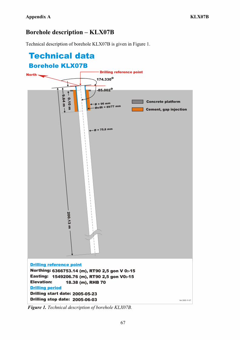
Appendix A KLX07B
67
Borehole description – KLX07B Technical description of borehole KLX07B is given in Figure 1. Technical dataBorehole KLX07B
6366753.14 (m),1549206.76 (m), 18.38 (m), 2005-05-23 2005-06-03
RT90 2,5 gon V0:-15 RHB 70
RT90 2,5 gon V 0:-15Northing:Easting:Elevation:
Drilling start date:Drilling stop date:
Drilling reference point
Drilling period
North174.330o
-85.002o
Drilling reference point
Cement, gap injection
Concrete platform
Ø = 75.8 mm
Øo/ = 89/77 mmØi
9.64 m Ø = 96 mm
200.13 m0.10 m
Ver 2005-11-07
Figure 1. Technical description of borehole KLX07B.
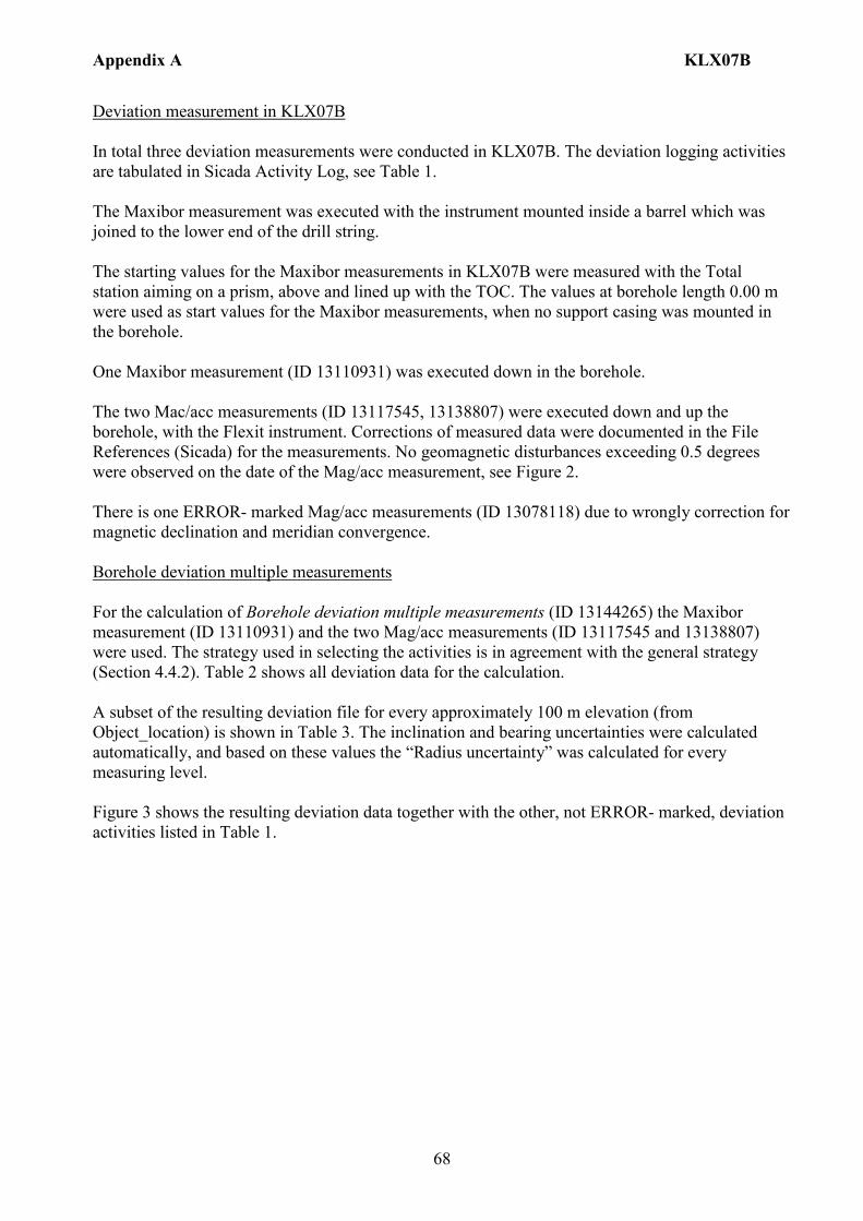
Appendix A KLX07B
68
Deviation measurement in KLX07B In total three deviation measurements were conducted in KLX07B. The deviation logging activities are tabulated in Sicada Activity Log, see Table 1. The Maxibor measurement was executed with the instrument mounted inside a barrel which was joined to the lower end of the drill string. The starting values for the Maxibor measurements in KLX07B were measured with the Total station aiming on a prism, above and lined up with the TOC. The values at borehole length 0.00 m were used as start values for the Maxibor measurements, when no support casing was mounted in the borehole. One Maxibor measurement (ID 13110931) was executed down in the borehole. The two Mac/acc measurements (ID 13117545, 13138807) were executed down and up the borehole, with the Flexit instrument. Corrections of measured data were documented in the File References (Sicada) for the measurements. No geomagnetic disturbances exceeding 0.5 degrees were observed on the date of the Mag/acc measurement, see Figure 2. There is one ERROR- marked Mag/acc measurements (ID 13078118) due to wrongly correction for magnetic declination and meridian convergence. Borehole deviation multiple measurements For the calculation of Borehole deviation multiple measurements (ID 13144265) the Maxibor measurement (ID 13110931) and the two Mag/acc measurements (ID 13117545 and 13138807) were used. The strategy used in selecting the activities is in agreement with the general strategy (Section 4.4.2). Table 2 shows all deviation data for the calculation. A subset of the resulting deviation file for every approximately 100 m elevation (from Object_location) is shown in Table 3. The inclination and bearing uncertainties were calculated automatically, and based on these values the “Radius uncertainty” was calculated for every measuring level. Figure 3 shows the resulting deviation data together with the other, not ERROR- marked, deviation activities listed in Table 1.

Appendix A KLX07B
69
Figure 2. The geomagnetic field was observed at the Observatory in Uppsala on 2005-07-09.
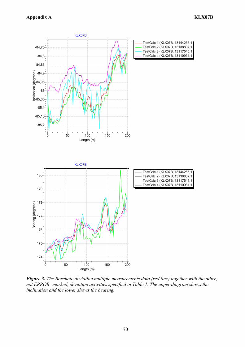
Appendix A KLX07B
70
TestCalc 1 (KLX07B, 13144265,1TestCalc 2 (KLX07B, 13138807,1TestCalc 3 (KLX07B, 13117545,1TestCalc 4 (KLX07B, 13110931,1
KLX07B
Length (m)200150100500
Incl
inat
ion
(deg
rees
)
-84,75
-84,8
-84,85
-84,9
-84,95
-85
-85,05
-85,1
-85,15
-85,2
TestCalc 1 (KLX07B, 13144265,1TestCalc 2 (KLX07B, 13138807,1TestCalc 3 (KLX07B, 13117545,1TestCalc 4 (KLX07B, 13110931,1
KLX07B
Length (m)200150100500
Bear
ing
(deg
rees
)
180
179
178
177
176
175
174
Figure 3. The Borehole deviation multiple measurements data (red line) together with the other, not ERROR- marked, deviation activities specified in Table 1. The upper diagram shows the inclination and the lower shows the bearing.
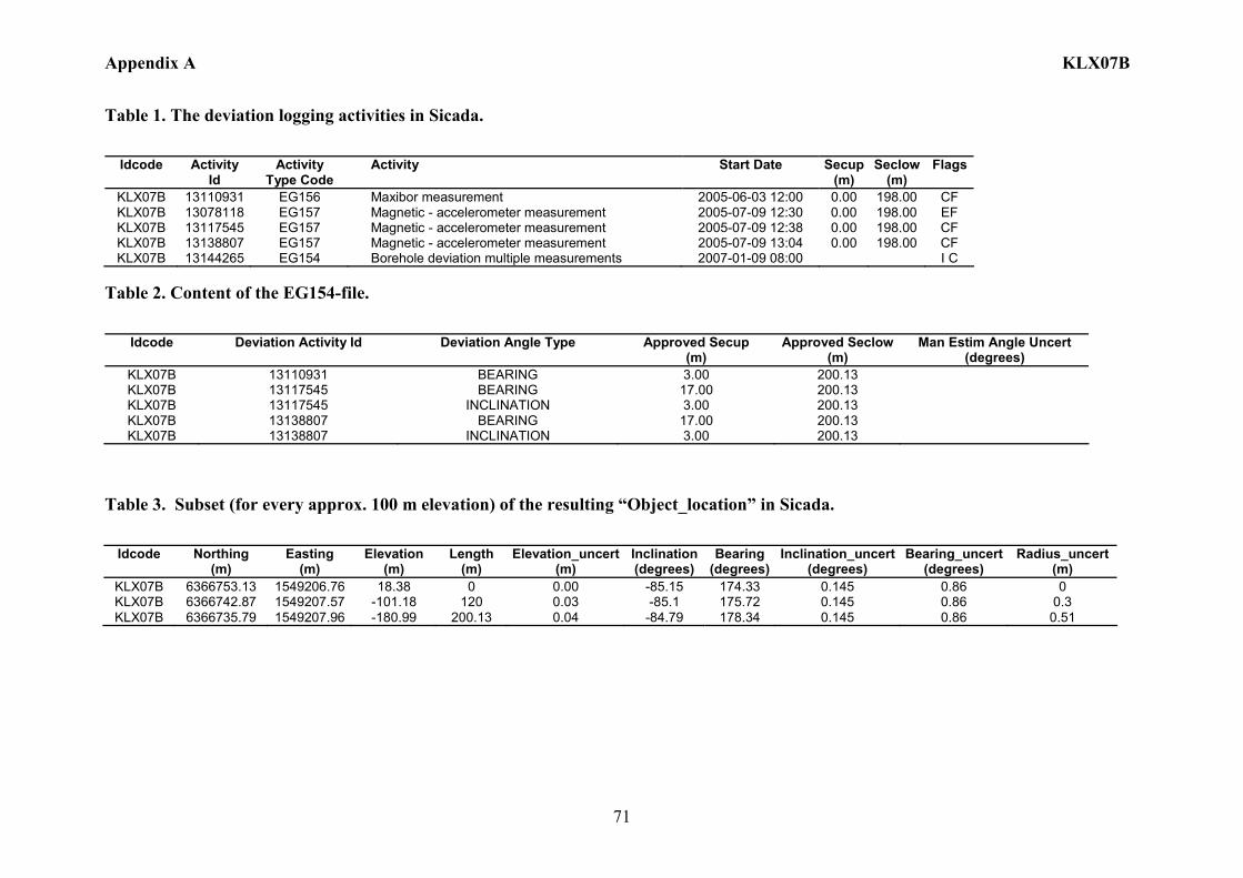
Appendix A KLX07B
71
Table 1. The deviation logging activities in Sicada.
Idcode Activity
Id Activity
Type Code Activity Start Date Secup
(m) Seclow
(m) Flags
KLX07B 13110931 EG156 Maxibor measurement 2005-06-03 12:00 0.00 198.00 CF KLX07B 13078118 EG157 Magnetic - accelerometer measurement 2005-07-09 12:30 0.00 198.00 EF KLX07B 13117545 EG157 Magnetic - accelerometer measurement 2005-07-09 12:38 0.00 198.00 CF KLX07B 13138807 EG157 Magnetic - accelerometer measurement 2005-07-09 13:04 0.00 198.00 CF KLX07B 13144265 EG154 Borehole deviation multiple measurements 2007-01-09 08:00 I C
Table 2. Content of the EG154-file.
Idcode Deviation Activity Id Deviation Angle Type Approved Secup (m)
Approved Seclow(m)
Man Estim Angle Uncert (degrees)
KLX07B 13110931 BEARING 3.00 200.13 KLX07B 13117545 BEARING 17.00 200.13 KLX07B 13117545 INCLINATION 3.00 200.13 KLX07B 13138807 BEARING 17.00 200.13 KLX07B 13138807 INCLINATION 3.00 200.13
Table 3. Subset (for every approx. 100 m elevation) of the resulting “Object_location” in Sicada.
Idcode
Northing (m)
Easting (m)
Elevation (m)
Length (m)
Elevation_uncert(m)
Inclination (degrees)
Bearing (degrees)
Inclination_uncert(degrees)
Bearing_uncert(degrees)
Radius_uncert (m)
KLX07B 6366753.13 1549206.76 18.38 0 0.00 -85.15 174.33 0.145 0.86 0 KLX07B 6366742.87 1549207.57 -101.18 120 0.03 -85.1 175.72 0.145 0.86 0.3 KLX07B 6366735.79 1549207.96 -180.99 200.13 0.04 -84.79 178.34 0.145 0.86 0.51
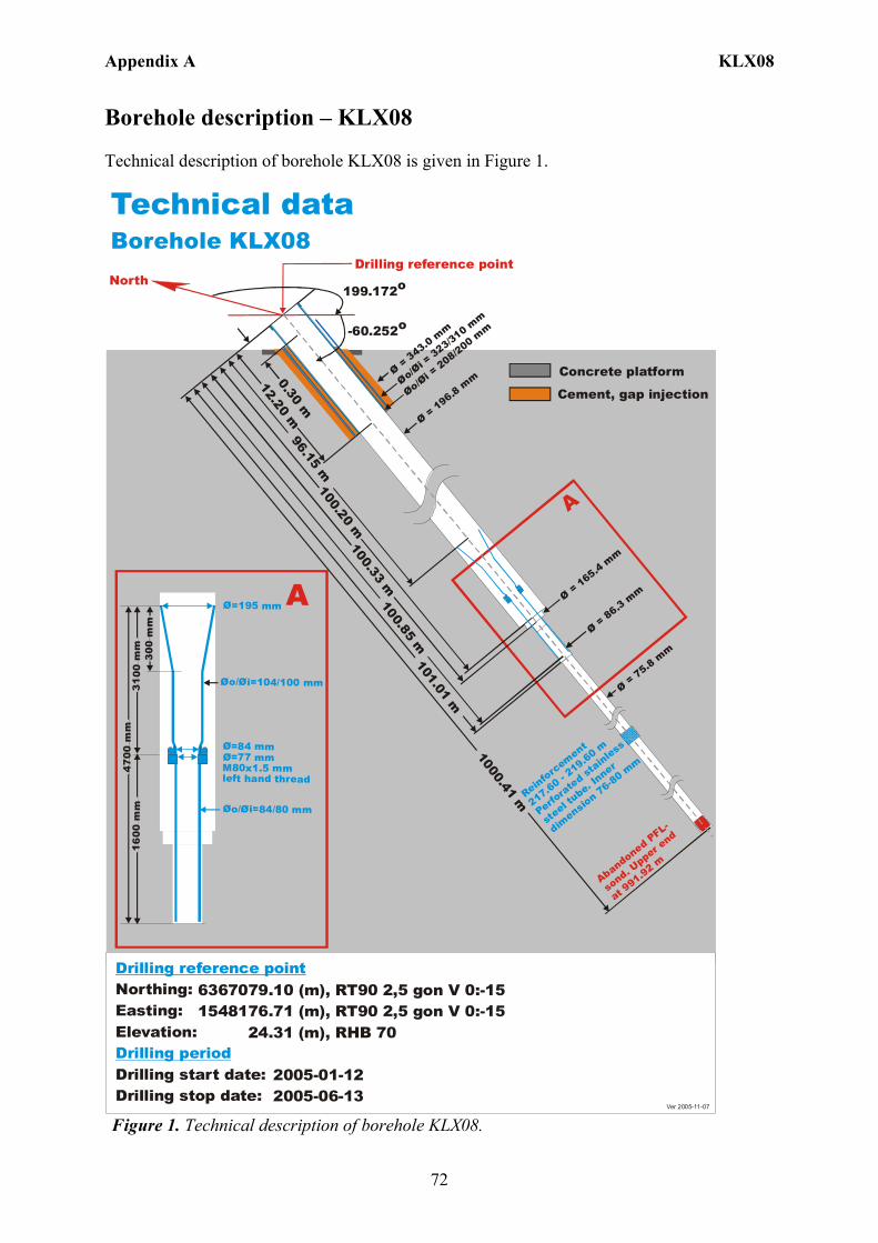
Appendix A KLX08
72
Borehole description – KLX08 Technical description of borehole KLX08 is given in Figure 1. Technical dataBorehole KLX08
6367079.10 (m),1548176.71 (m), 24.31 (m), 2005-01-12 2005-06-13
RT90 2,5 gon V 0:-15 RHB 70
RT90 2,5 gon V 0:-15Northing:Easting:Elevation:
Drilling start date:Drilling stop date:
Drilling reference point
Drilling period
North199.172o
-60.252o
Drilling reference point
Ø=195 mm
Øo/ =104/100 mmØi
Ø=84 mmØ=77 mm M80x1.5 mm left hand thread
Øo/ =84/80 mmØi
300
mm
3100
mm
470
0 m
m1 6
00 m
m
A
Ø = 196.8 mmØo/
= 323/310 mm
Øi
Øo/= 208/200 m
m
Øi
Ø = 75.8 mm
A
0.30 m
12.20 m
101.01 m
Ø = 343.0 mm
100.33 m
96.15 m
1000.41 m
Ø = 165.4 mm
Ø = 86.3 mm
100.20 m
100.85 m
Reinforcement
217.60 - 219.60 m
Perfora
ted stainless
steel t
ube. Inner
dimensio
n 76-80 mm
Abandoned PFL-
sond. U
pper end
at 991.92 m
Cement, gap injection
Concrete platform
Ver 2005-11-07 Figure 1. Technical description of borehole KLX08.
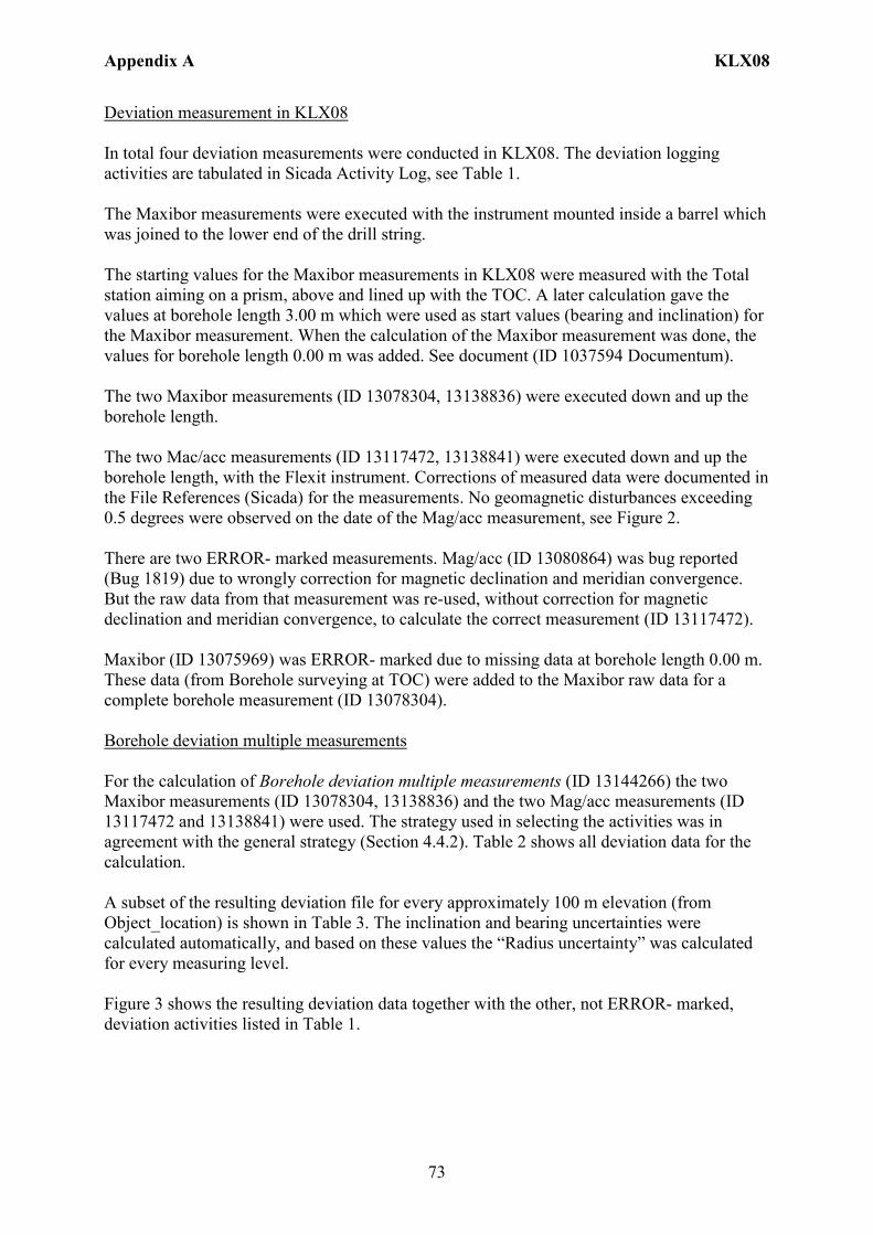
Appendix A KLX08
73
Deviation measurement in KLX08 In total four deviation measurements were conducted in KLX08. The deviation logging activities are tabulated in Sicada Activity Log, see Table 1. The Maxibor measurements were executed with the instrument mounted inside a barrel which was joined to the lower end of the drill string. The starting values for the Maxibor measurements in KLX08 were measured with the Total station aiming on a prism, above and lined up with the TOC. A later calculation gave the values at borehole length 3.00 m which were used as start values (bearing and inclination) for the Maxibor measurement. When the calculation of the Maxibor measurement was done, the values for borehole length 0.00 m was added. See document (ID 1037594 Documentum). The two Maxibor measurements (ID 13078304, 13138836) were executed down and up the borehole length. The two Mac/acc measurements (ID 13117472, 13138841) were executed down and up the borehole length, with the Flexit instrument. Corrections of measured data were documented in the File References (Sicada) for the measurements. No geomagnetic disturbances exceeding 0.5 degrees were observed on the date of the Mag/acc measurement, see Figure 2. There are two ERROR- marked measurements. Mag/acc (ID 13080864) was bug reported (Bug 1819) due to wrongly correction for magnetic declination and meridian convergence. But the raw data from that measurement was re-used, without correction for magnetic declination and meridian convergence, to calculate the correct measurement (ID 13117472). Maxibor (ID 13075969) was ERROR- marked due to missing data at borehole length 0.00 m. These data (from Borehole surveying at TOC) were added to the Maxibor raw data for a complete borehole measurement (ID 13078304). Borehole deviation multiple measurements For the calculation of Borehole deviation multiple measurements (ID 13144266) the two Maxibor measurements (ID 13078304, 13138836) and the two Mag/acc measurements (ID 13117472 and 13138841) were used. The strategy used in selecting the activities was in agreement with the general strategy (Section 4.4.2). Table 2 shows all deviation data for the calculation. A subset of the resulting deviation file for every approximately 100 m elevation (from Object_location) is shown in Table 3. The inclination and bearing uncertainties were calculated automatically, and based on these values the “Radius uncertainty” was calculated for every measuring level. Figure 3 shows the resulting deviation data together with the other, not ERROR- marked, deviation activities listed in Table 1.

Appendix A KLX08
74
Figure 2. The geomagnetic field was observed at the Observatory in Uppsala on 2005-09-06.
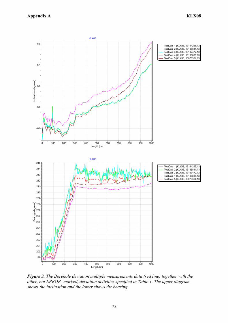
Appendix A KLX08
75
TestCalc 1 (KLX08, 13144266,13TestCalc 2 (KLX08, 13138841,13TestCalc 3 (KLX08, 13117472,13TestCalc 4 (KLX08, 13138836,13TestCalc 5 (KLX08, 13078304,13
KLX08
Length (m)10009008007006005004003002001000
Incl
inat
ion
(deg
rees
)
-56
-57
-58
-59
-60
TestCalc 1 (KLX08, 13144266,13TestCalc 2 (KLX08, 13138841,13TestCalc 3 (KLX08, 13117472,13TestCalc 4 (KLX08, 13138836,13TestCalc 5 (KLX08, 13078304,13
KLX08
Length (m)10009008007006005004003002001000
Bear
ing
(deg
rees
)
215
214
213
212
211
210
209
208
207
206
205
204
203
202
201
200
199
Figure 3. The Borehole deviation multiple measurements data (red line) together with the other, not ERROR- marked, deviation activities specified in Table 1. The upper diagram shows the inclination and the lower shows the bearing.
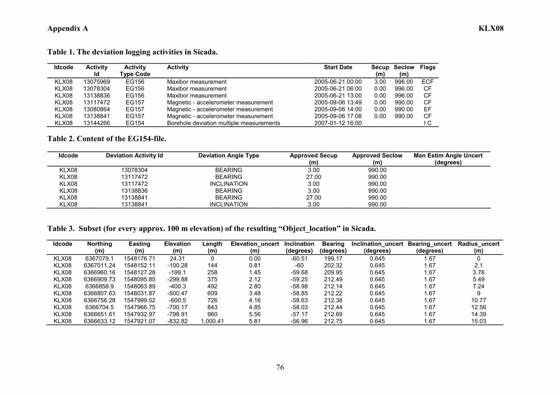
Appendix A KLX08
76
Table 1. The deviation logging activities in Sicada.
Idcode Activity Id
Activity Type Code
Activity Start Date Secup(m)
Seclow(m)
Flags
KLX08 13075969 EG156 Maxibor measurement 2005-06-21 00:00 3.00 996.00 ECF KLX08 13078304 EG156 Maxibor measurement 2005-06-21 06:00 0.00 996.00 CF KLX08 13138836 EG156 Maxibor measurement 2005-06-21 13:00 0.00 996.00 CF KLX08 13117472 EG157 Magnetic - accelerometer measurement 2005-09-06 13:49 0.00 990.00 CF KLX08 13080864 EG157 Magnetic - accelerometer measurement 2005-09-06 14:00 0.00 990.00 EF KLX08 13138841 EG157 Magnetic - accelerometer measurement 2005-09-06 17:08 0.00 990.00 CF KLX08 13144266 EG154 Borehole deviation multiple measurements 2007-01-12 16:00 I C
Table 2. Content of the EG154-file.
Idcode Deviation Activity Id Deviation Angle Type Approved Secup (m)
Approved Seclow(m)
Man Estim Angle Uncert (degrees)
KLX08 13078304 BEARING 3.00 990.00 KLX08 13117472 BEARING 27.00 990.00 KLX08 13117472 INCLINATION 3.00 990.00 KLX08 13138836 BEARING 3.00 990.00 KLX08 13138841 BEARING 27.00 990.00 KLX08 13138841 INCLINATION 3.00 990.00
Table 3. Subset (for every approx. 100 m elevation) of the resulting “Object_location” in Sicada.
Idcode
Northing (m)
Easting (m)
Elevation (m)
Length (m)
Elevation_uncert(m)
Inclination (degrees)
Bearing (degrees)
Inclination_uncert(degrees)
Bearing_uncert(degrees)
Radius_uncert (m)
KLX08 6367079.1 1548176.71 24.31 0 0.00 -60.51 199.17 0.645 1.67 0 KLX08 6367011.24 1548152.11 -100.28 144 0.81 -60 202.32 0.645 1.67 2.1 KLX08 6366960.16 1548127.28 -199.1 258 1.45 -59.68 209.95 0.645 1.67 3.76 KLX08 6366909.73 1548095.85 -299.88 375 2.12 -59.25 212.49 0.645 1.67 5.49 KLX08 6366858.9 1548063.89 -400.3 492 2.80 -58.98 212.14 0.645 1.67 7.24 KLX08 6366807.63 1548031.87 -500.47 609 3.48 -58.85 212.22 0.645 1.67 9 KLX08 6366756.28 1547999.52 -600.5 726 4.16 -58.63 212.38 0.645 1.67 10.77 KLX08 6366704.5 1547966.75 -700.17 843 4.85 -58.03 212.44 0.645 1.67 12.56 KLX08 6366651.61 1547932.97 -798.91 960 5.56 -57.17 212.69 0.645 1.67 14.39 KLX08 6366633.12 1547921.07 -832.82 1,000.41 5.81 -56.96 212.75 0.645 1.67 15.03
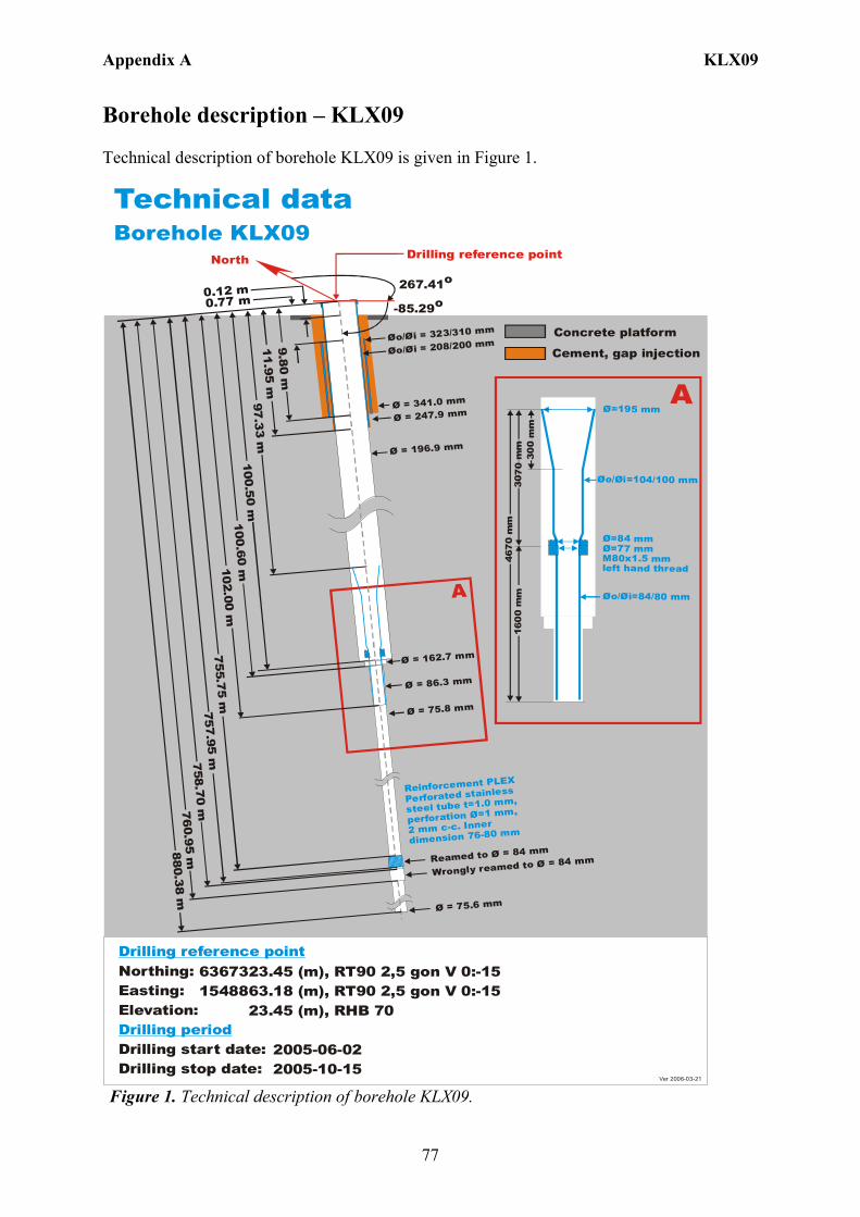
Appendix A KLX09
77
Borehole description – KLX09 Technical description of borehole KLX09 is given in Figure 1. Technical dataBorehole KLX09
6367323.45 (m),1548863.18 (m), 23.45 (m), 2005-06-02 2005-10-15
RT90 2,5 gon V 0:-15 RHB 70
RT90 2,5 gon V 0:-15Northing:Easting:Elevation:
Drilling start date:Drilling stop date:
Drilling reference point
Drilling period
North
267.41o
-85.29o
Drilling reference point
Ø=195 mm
Øo/ =104/100 mmØi
Ø=84 mmØ=77 mm M80x1.5 mm left hand thread
Øo/ =84/80 mmØi
300
mm
307
0 m
m46
70
mm
1 60
0 m
m
A
Ø = 196.9 mm
Øo/ = 323/310 mmØi
Øo/ = 208/200 mmØi
Ø = 75.8 mm
A
0.12 m
97.33 m
Ø = 341.0 mm
100.60 m
880 .38 mØ = 162.7 mm
Ø = 86.3 mm
102.00 m
Reinforcement PLEX
Perforated stainless
steel tube t=1.0 mm,
perforation =1 mm,
2 mm c-c. Inner
dimension 76-80 mm
Ø
Cement, gap injection
Concrete platform
Ver 2006-03-21
9.80 m11.95 m
Ø = 247.9 mm
100.50 m
Ø = 75.6 mm
Reamed to Ø = 84 mm
Wrongly reamed to Ø = 84 mm
0.77 m
760.95 m758. 70 m
75 7.95 m755.75 m
Figure 1. Technical description of borehole KLX09.
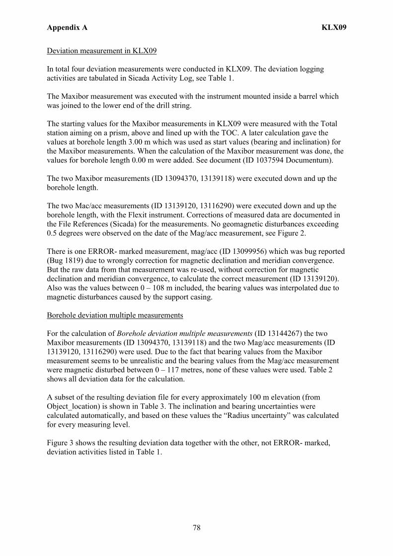
Appendix A KLX09
78
Deviation measurement in KLX09 In total four deviation measurements were conducted in KLX09. The deviation logging activities are tabulated in Sicada Activity Log, see Table 1. The Maxibor measurement was executed with the instrument mounted inside a barrel which was joined to the lower end of the drill string. The starting values for the Maxibor measurements in KLX09 were measured with the Total station aiming on a prism, above and lined up with the TOC. A later calculation gave the values at borehole length 3.00 m which was used as start values (bearing and inclination) for the Maxibor measurements. When the calculation of the Maxibor measurement was done, the values for borehole length 0.00 m were added. See document (ID 1037594 Documentum). The two Maxibor measurements (ID 13094370, 13139118) were executed down and up the borehole length. The two Mac/acc measurements (ID 13139120, 13116290) were executed down and up the borehole length, with the Flexit instrument. Corrections of measured data are documented in the File References (Sicada) for the measurements. No geomagnetic disturbances exceeding 0.5 degrees were observed on the date of the Mag/acc measurement, see Figure 2. There is one ERROR- marked measurement, mag/acc (ID 13099956) which was bug reported (Bug 1819) due to wrongly correction for magnetic declination and meridian convergence. But the raw data from that measurement was re-used, without correction for magnetic declination and meridian convergence, to calculate the correct measurement (ID 13139120). Also was the values between 0 – 108 m included, the bearing values was interpolated due to magnetic disturbances caused by the support casing. Borehole deviation multiple measurements For the calculation of Borehole deviation multiple measurements (ID 13144267) the two Maxibor measurements (ID 13094370, 13139118) and the two Mag/acc measurements (ID 13139120, 13116290) were used. Due to the fact that bearing values from the Maxibor measurement seems to be unrealistic and the bearing values from the Mag/acc measurement were magnetic disturbed between 0 – 117 metres, none of these values were used. Table 2 shows all deviation data for the calculation. A subset of the resulting deviation file for every approximately 100 m elevation (from Object_location) is shown in Table 3. The inclination and bearing uncertainties were calculated automatically, and based on these values the “Radius uncertainty” was calculated for every measuring level. Figure 3 shows the resulting deviation data together with the other, not ERROR- marked, deviation activities listed in Table 1.

Appendix A KLX09
79
Figure 2. The geomagnetic field was observed at the Observatory in Uppsala on 2005-10-26.
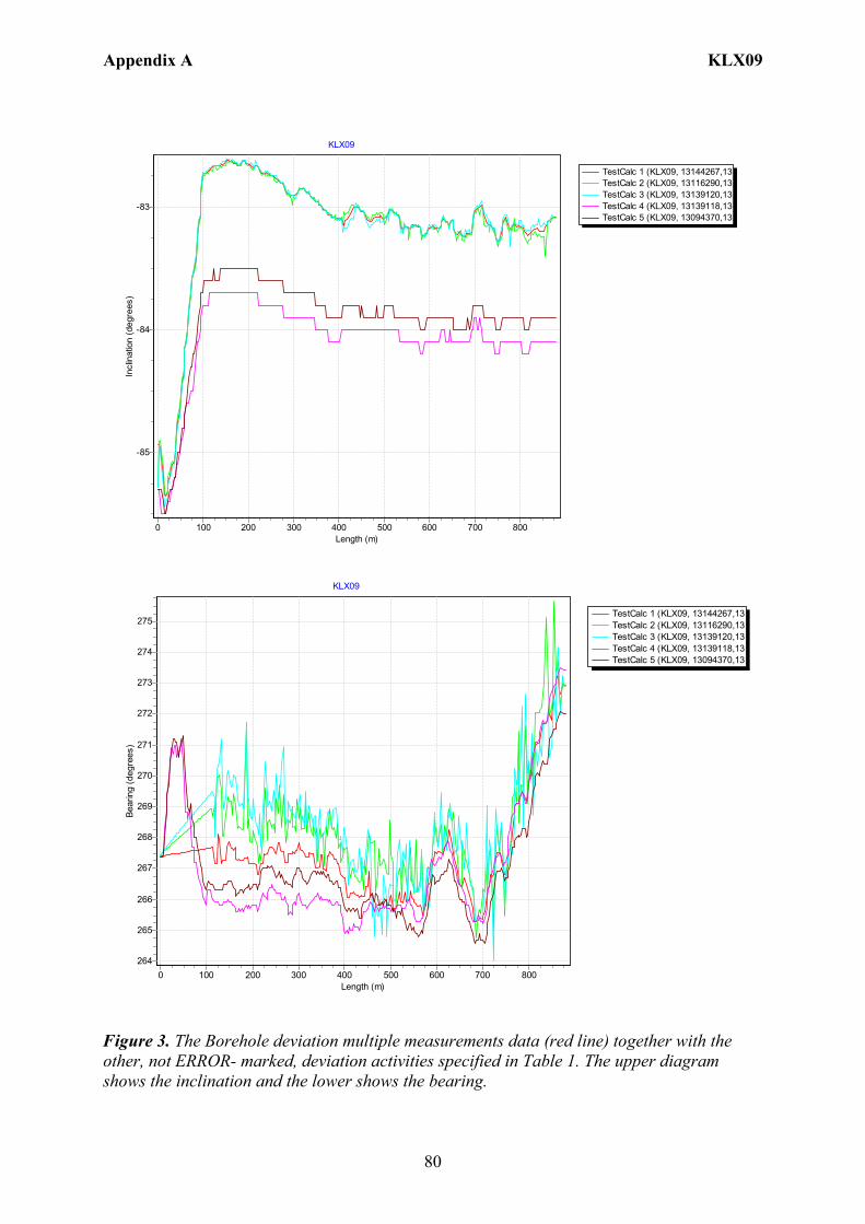
Appendix A KLX09
80
TestCalc 1 (KLX09, 13144267,13TestCalc 2 (KLX09, 13116290,13TestCalc 3 (KLX09, 13139120,13TestCalc 4 (KLX09, 13139118,13TestCalc 5 (KLX09, 13094370,13
KLX09
Length (m)8007006005004003002001000
Incl
inat
ion
(deg
rees
)
-83
-84
-85
TestCalc 1 (KLX09, 13144267,13TestCalc 2 (KLX09, 13116290,13TestCalc 3 (KLX09, 13139120,13TestCalc 4 (KLX09, 13139118,13TestCalc 5 (KLX09, 13094370,13
KLX09
Length (m)8007006005004003002001000
Bear
ing
(deg
rees
)
275
274
273
272
271
270
269
268
267
266
265
264
Figure 3. The Borehole deviation multiple measurements data (red line) together with the other, not ERROR- marked, deviation activities specified in Table 1. The upper diagram shows the inclination and the lower shows the bearing.
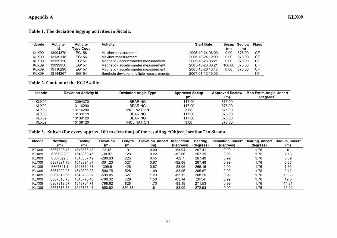
Appendix A KLX09
81
Table 1. The deviation logging activities in Sicada.
Idcode Activity
Id Activity
Type Code Activity Start Date Secup
(m) Seclow
(m) Flags
KLX09 13094370 EG156 Maxibor measurement 2005-10-24 06:00 0.00 876.00 CF KLX09 13139118 EG156 Maxibor measurement 2005-10-24 12:00 0.00 876.00 CF KLX09 13139120 EG157 Magnetic - accelerometer measurement 2005-10-26 06:21 0.00 876.00 CF KLX09 13099956 EG157 Magnetic - accelerometer measurement 2005-10-26 06:21 108.00 876.00 EF KLX09 13116290 EG157 Magnetic - accelerometer measurement 2005-10-26 10:43 0.00 876.00 CF KLX09 13144267 EG154 Borehole deviation multiple measurements 2007-01-12 16:00 I C
Table 2. Content of the EG154-file.
Idcode Deviation Activity Id Deviation Angle Type Approved Secup (m)
Approved Seclow(m)
Man Estim Angle Uncert (degrees)
KLX09 13094370 BEARING 117.00 876.00 KLX09 13116290 BEARING 117.00 876.00 KLX09 13116290 INCLINATION 3.00 876.00 KLX09 13139118 BEARING 117.00 876.00 KLX09 13139120 BEARING 117.00 876.00 KLX09 13139120 INCLINATION 3.00 876.00
Table 3. Subset (for every approx. 100 m elevation) of the resulting “Object_location” in Sicada.
Idcode
Northing (m)
Easting (m)
Elevation (m)
Length (m)
Elevation_uncert(m)
Inclination (degrees)
Bearing (degrees)
Inclination_uncert(degrees)
Bearing_uncert(degrees)
Radius_uncert (m)
KLX09 6367323.45 1548863.18 23.45 0 0.00 -84.94 267.41 0.99 1.76 0 KLX09 6367322.9 1548850.45 -98.87 123 0.22 -82.66 267.15 0.99 1.76 2.13 KLX09 6367322.3 1548837.42 -200.03 225 0.45 -82.7 267.49 0.99 1.76 3.89 KLX09 6367321.75 1548824.67 -301.23 327 0.67 -82.88 267.48 0.99 1.76 5.65 KLX09 6367321.1 1548812.67 -399.5 426 0.87 -83.06 266.15 0.99 1.76 7.36 KLX09 6367320.25 1548800.38 -500.75 528 1.09 -83.06 265.87 0.99 1.76 9.12 KLX09 6367319.55 1548788.62 -599.05 627 1.29 -83.12 268.26 0.99 1.76 10.83 KLX09 6367318.78 1548776.46 -700.32 729 1.50 -83.14 267.4 0.99 1.76 12.6 KLX09 6367318.57 1548764.71 -798.62 828 1.70 -83.19 271.53 0.99 1.76 14.31 KLX09 6367318.83 1548758.47 -850.62 880.38 1.81 -83.09 272.93 0.99 1.76 15.21
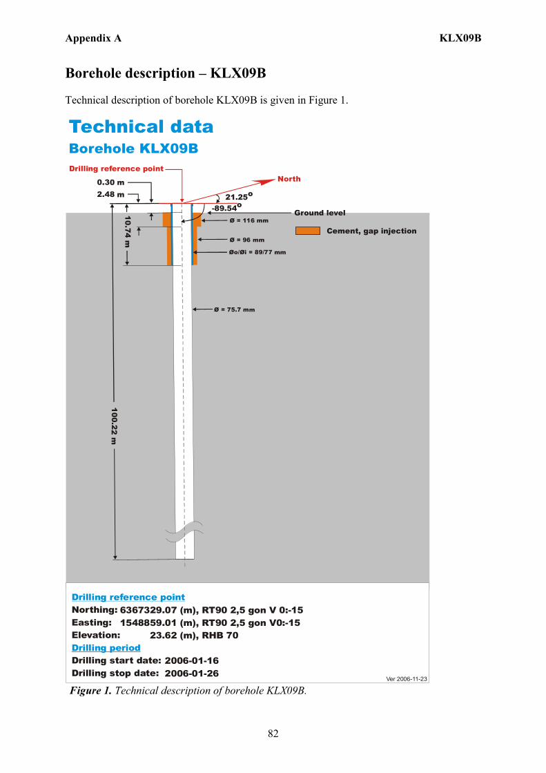
Appendix A KLX09B
82
Borehole description – KLX09B Technical description of borehole KLX09B is given in Figure 1.
6367329.07 (m),1548859.01 (m), 23.62 (m), 2006-01-16 2006-01-26
RT90 2,5 gon V0:-15 RHB 70
RT90 2,5 gon V 0:-15Northing:Easting:Elevation:
Drilling start date:Drilling stop date:
Drilling reference point
Drilling period
Cement, gap injection
Ver 2006-11-23
Øo/ = 89/77 mmØi
Ø = 96 mm
100.22 m
10.74 m
0.30 m
Ø = 75.7 mm
Technical dataBorehole KLX09B
North
21.25o
-89.54o
Drilling reference point
Ground level
2.48 m
Ø = 116 mm
Figure 1. Technical description of borehole KLX09B.
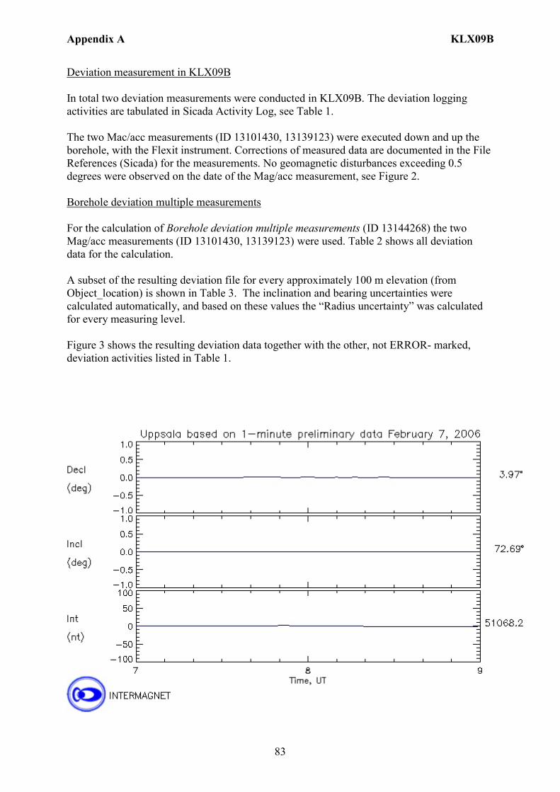
Appendix A KLX09B
83
Deviation measurement in KLX09B In total two deviation measurements were conducted in KLX09B. The deviation logging activities are tabulated in Sicada Activity Log, see Table 1. The two Mac/acc measurements (ID 13101430, 13139123) were executed down and up the borehole, with the Flexit instrument. Corrections of measured data are documented in the File References (Sicada) for the measurements. No geomagnetic disturbances exceeding 0.5 degrees were observed on the date of the Mag/acc measurement, see Figure 2. Borehole deviation multiple measurements For the calculation of Borehole deviation multiple measurements (ID 13144268) the two Mag/acc measurements (ID 13101430, 13139123) were used. Table 2 shows all deviation data for the calculation. A subset of the resulting deviation file for every approximately 100 m elevation (from Object_location) is shown in Table 3. The inclination and bearing uncertainties were calculated automatically, and based on these values the “Radius uncertainty” was calculated for every measuring level. Figure 3 shows the resulting deviation data together with the other, not ERROR- marked, deviation activities listed in Table 1.
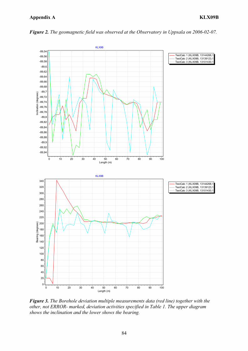
Appendix A KLX09B
84
Figure 2. The geomagnetic field was observed at the Observatory in Uppsala on 2006-02-07.
TestCalc 1 (KLX09B, 13144268,1TestCalc 2 (KLX09B, 13139123,1TestCalc 3 (KLX09B, 13101430,1
KLX9B
Length (m)1009080706050403020100
Incl
inat
ion
(deg
rees
)
-89,54
-89,56
-89,58
-89,6
-89,62
-89,64
-89,66
-89,68
-89,7
-89,72
-89,74
-89,76
-89,78
-89,8
-89,82
-89,84
-89,86
-89,88
-89,9
-89,92
-89,94
TestCalc 1 (KLX09B, 13144268,1TestCalc 2 (KLX09B, 13139123,1TestCalc 3 (KLX09B, 13101430,1
KLX9B
Length (m)1009080706050403020100
Bear
ing
(deg
rees
)
340
320
300
280
260
240
220
200
180
160
140
120
100
80
60
40
20
0
Figure 3. The Borehole deviation multiple measurements data (red line) together with the other, not ERROR- marked, deviation activities specified in Table 1. The upper diagram shows the inclination and the lower shows the bearing.
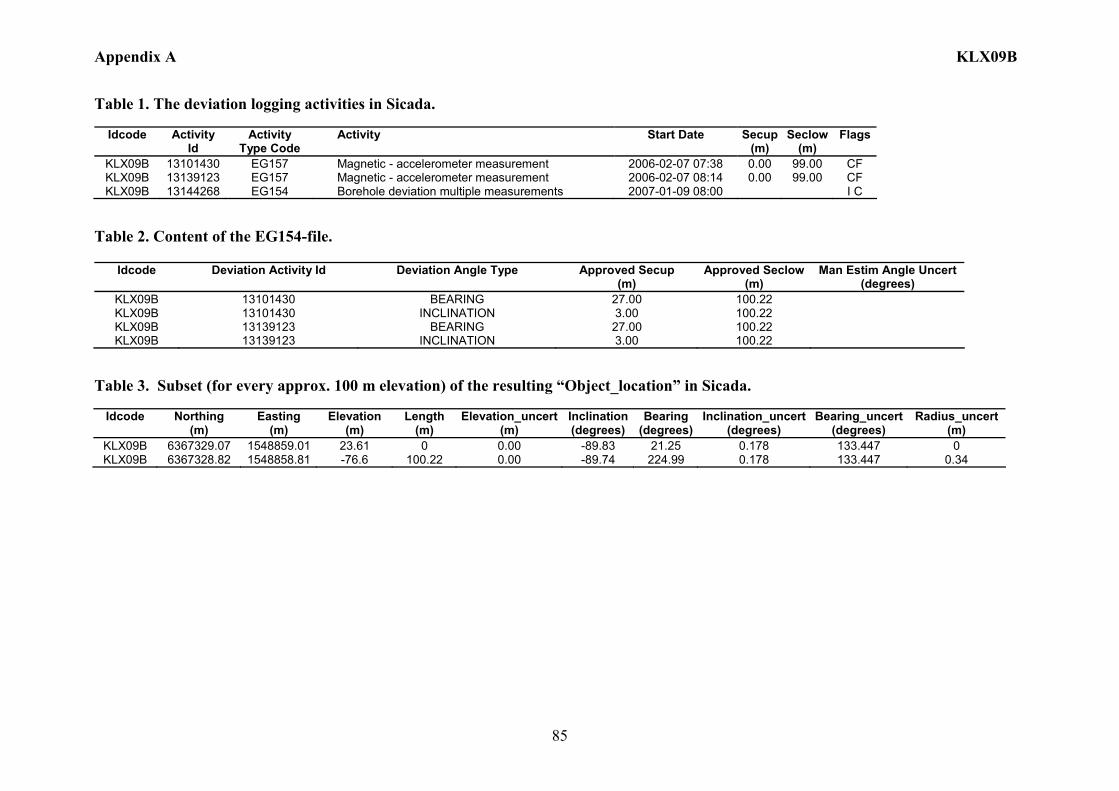
Appendix A KLX09B
85
Table 1. The deviation logging activities in Sicada.
Idcode Activity Id
Activity Type Code
Activity Start Date Secup(m)
Seclow(m)
Flags
KLX09B 13101430 EG157 Magnetic - accelerometer measurement 2006-02-07 07:38 0.00 99.00 CF KLX09B 13139123 EG157 Magnetic - accelerometer measurement 2006-02-07 08:14 0.00 99.00 CF KLX09B 13144268 EG154 Borehole deviation multiple measurements 2007-01-09 08:00 I C
Table 2. Content of the EG154-file.
Idcode Deviation Activity Id Deviation Angle Type Approved Secup (m)
Approved Seclow(m)
Man Estim Angle Uncert (degrees)
KLX09B 13101430 BEARING 27.00 100.22 KLX09B 13101430 INCLINATION 3.00 100.22 KLX09B 13139123 BEARING 27.00 100.22 KLX09B 13139123 INCLINATION 3.00 100.22
Table 3. Subset (for every approx. 100 m elevation) of the resulting “Object_location” in Sicada.
Idcode
Northing
(m) Easting
(m) Elevation
(m) Length
(m) Elevation_uncert
(m) Inclination (degrees)
Bearing (degrees)
Inclination_uncert(degrees)
Bearing_uncert(degrees)
Radius_uncert (m)
KLX09B 6367329.07 1548859.01 23.61 0 0.00 -89.83 21.25 0.178 133.447 0 KLX09B 6367328.82 1548858.81 -76.6 100.22 0.00 -89.74 224.99 0.178 133.447 0.34
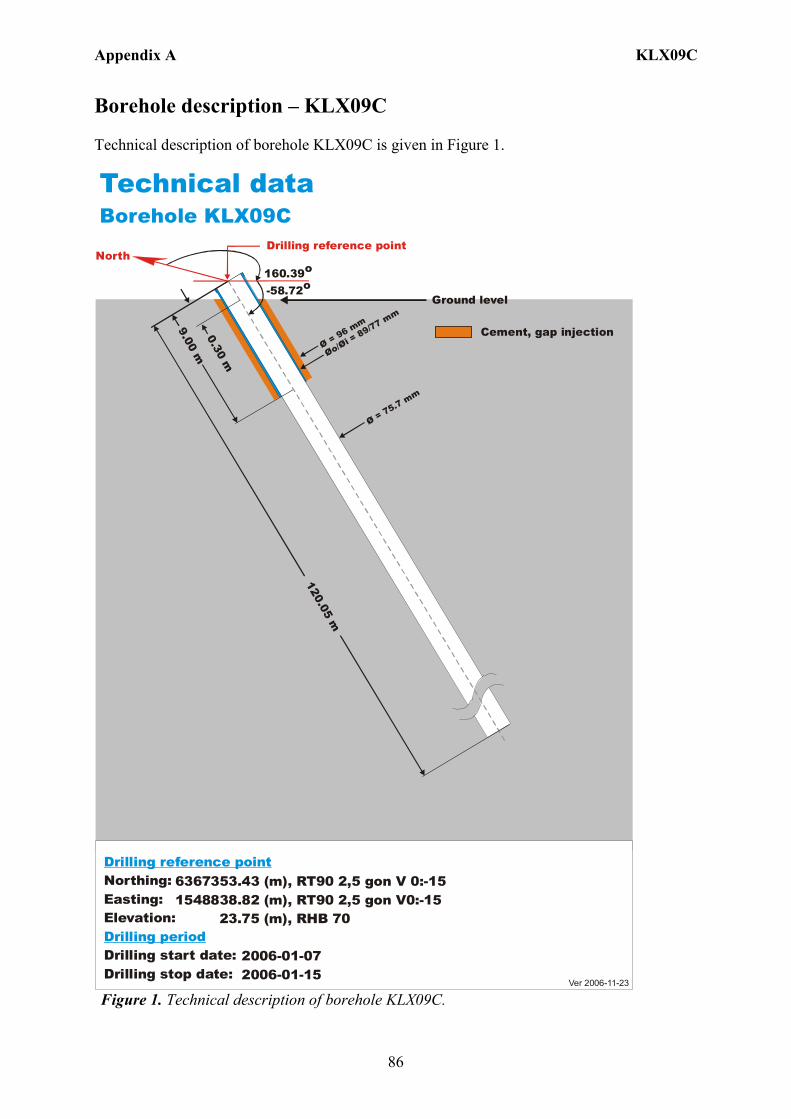
Appendix A KLX09C
86
Borehole description – KLX09C Technical description of borehole KLX09C is given in Figure 1.
6367353.43 (m),1548838.82 (m), 23.75 (m), 2006-01-07 2006-01-15
RT90 2,5 gon V0:-15 RHB 70
RT90 2,5 gon V 0:-15Northing:Easting:Elevation:
Drilling start date:Drilling stop date:
Drilling reference point
Drilling period
Cement, gap injection
Ver 2006-11-23
Technical dataBorehole KLX09C
North160.39o
-58.72o
Drilling reference point
Øo/= 89/77 mm
Øi Ø = 96 mm
120.05 m
9.00 m0.30 m
Ø = 75.7 mm
Ground level
Figure 1. Technical description of borehole KLX09C.

Appendix A KLX09C
87
Deviation measurement in KLX09C In total two deviation measurements were conducted in KLX09C. The deviation logging activities are tabulated in Sicada Activity Log, see Table 1. The two Mac/acc measurements (ID 13101433, 13139125) were executed down and up the borehole, with the Flexit instrument. Corrections of measured data were documented in the File References (Sicada) for the measurements. No geomagnetic disturbances exceeding 0.5 degrees were observed on the date of the Mag/acc measurement, see Figure 2. Borehole deviation multiple measurements For the calculation of Borehole deviation multiple measurements (ID 13144269) the two Mag/acc measurements (ID 13101433, 13139125) were used. Table 2 shows all deviation data for the calculation. A subset of the resulting deviation file for every approximately 100 m elevation (from Object_location) is shown in Table 3. The inclination and bearing uncertainties were calculated automatically, and based on these values the “Radius uncertainty” was calculated for every measuring level. Figure 3 shows the resulting deviation data together with the other, not ERROR- marked, deviation activities listed in Table 1.
Figure 2. The geomagnetic field was observed at the Observatory in Uppsala on 2006-02-09.
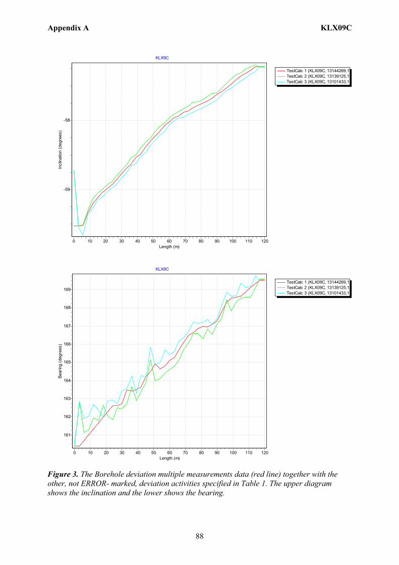
Appendix A KLX09C
88
TestCalc 1 (KLX09C, 13144269,1TestCalc 2 (KLX09C, 13139125,1TestCalc 3 (KLX09C, 13101433,1
KLX9C
Length (m)1201101009080706050403020100
Incl
inat
ion
(deg
rees
)
-58
-59
TestCalc 1 (KLX09C, 13144269,1TestCalc 2 (KLX09C, 13139125,1TestCalc 3 (KLX09C, 13101433,1
KLX9C
Length (m)1201101009080706050403020100
Bear
ing
(deg
rees
)
169
168
167
166
165
164
163
162
161
Figure 3. The Borehole deviation multiple measurements data (red line) together with the other, not ERROR- marked, deviation activities specified in Table 1. The upper diagram shows the inclination and the lower shows the bearing.

Appendix A KLX09C
89
Table 1. The deviation logging activities in Sicada.
Idcode Activity Id
Activity Type Code
Activity Start Date Secup(m)
Seclow(m)
Flags
KLX09C 13101433 EG157 Magnetic - accelerometer measurement 2006-02-09 17:20 0.00 117.00 CF KLX09C 13139125 EG157 Magnetic - accelerometer measurement 2006-02-09 17:53 0.00 117.00 CF KLX09C 13144269 EG154 Borehole deviation multiple measurements 2007-01-09 08:00 I C
Table 2. Content of the EG154-file.
Idcode Deviation Activity Id Deviation Angle Type Approved Secup (m)
Approved Seclow(m)
Man Estim Angle Uncert (degrees)
KLX09C 13101433 BEARING 27.00 120.05 KLX09C 13101433 INCLINATION 3.00 120.05 KLX09C 13139125 BEARING 27.00 120.05 KLX09C 13139125 INCLINATION 3.00 120.05
Table 3. Subset (for every approx. 100 m elevation) of the resulting “Object_location” in Sicada.
Idcode
Northing
(m) Easting
(m) Elevation
(m) Length
(m) Elevation_uncert
(m) Inclination (degrees)
Bearing (degrees)
Inclination_uncert(degrees)
Bearing_uncert(degrees)
Radius_uncert (m)
KLX09C 6367353.43 1548838.82 23.75 0 0.00 -59.52 160.39 0.085 0.82 0 KLX09C 6367292.31 1548854.89 -78.26 120.05 0.09 -57.22 169.55 0.085 0.82 0.91
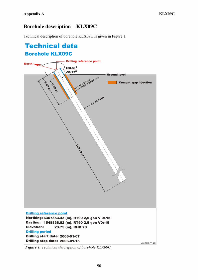
Appendix A KLX09C
90
Borehole description – KLX09C Technical description of borehole KLX09C is given in Figure 1.
6367353.43 (m),1548838.82 (m), 23.75 (m), 2006-01-07 2006-01-15
RT90 2,5 gon V0:-15 RHB 70
RT90 2,5 gon V 0:-15Northing:Easting:Elevation:
Drilling start date:Drilling stop date:
Drilling reference point
Drilling period
Cement, gap injection
Ver 2006-11-23
Technical dataBorehole KLX09C
North160.39o
-58.72o
Drilling reference point
Øo/= 89/77 m
m
Øi Ø = 96 mm
120.05 m
9.00 m0.30 m
Ø = 75.7 mm
Ground level
Figure 1. Technical description of borehole KLX09C.

Appendix A KLX09C
91
Deviation measurement in KLX09C In total two deviation measurements were conducted in KLX09C. The deviation logging activities are tabulated in Sicada Activity Log, see Table 1. The two Mac/acc measurements (ID 13101433, 13139125) were executed down and up the borehole, with the Flexit instrument. Corrections of measured data were documented in the File References (Sicada) for the measurements. No geomagnetic disturbances exceeding 0.5 degrees were observed on the date of the Mag/acc measurement, see Figure 2. Borehole deviation multiple measurements For the calculation of Borehole deviation multiple measurements (ID 13144269) the two Mag/acc measurements (ID 13101433, 13139125) were used. Table 2 shows all deviation data for the calculation. A subset of the resulting deviation file for every approximately 100 m elevation (from Object_location) is shown in Table 3. The inclination and bearing uncertainties were calculated automatically, and based on these values the “Radius uncertainty” was calculated for every measuring level. Figure 3 shows the resulting deviation data together with the other, not ERROR- marked, deviation activities listed in Table 1.
Figure 2. The geomagnetic field was observed at the Observatory in Uppsala on 2006-02-09.
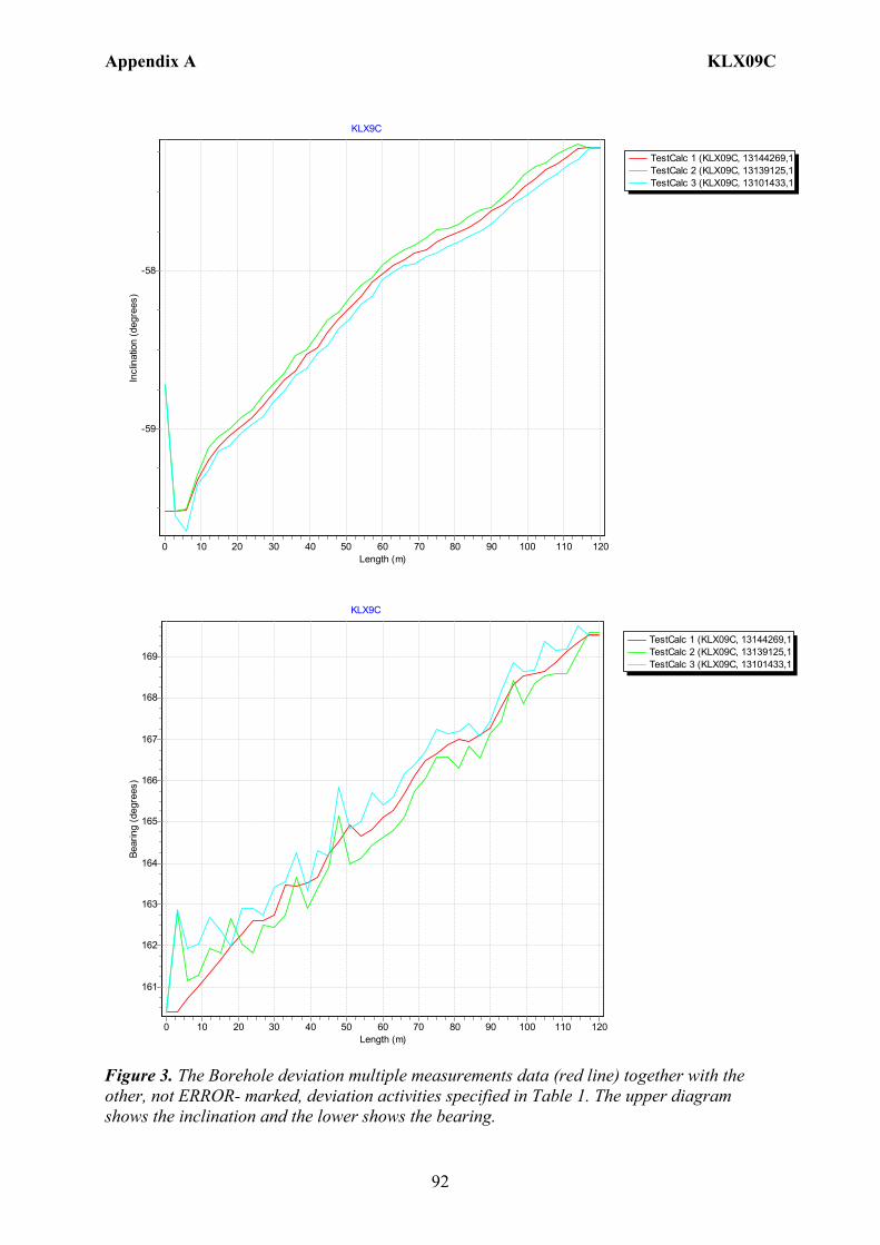
Appendix A KLX09C
92
TestCalc 1 (KLX09C, 13144269,1TestCalc 2 (KLX09C, 13139125,1TestCalc 3 (KLX09C, 13101433,1
KLX9C
Length (m)1201101009080706050403020100
Incl
inat
ion
(deg
rees
)
-58
-59
TestCalc 1 (KLX09C, 13144269,1TestCalc 2 (KLX09C, 13139125,1TestCalc 3 (KLX09C, 13101433,1
KLX9C
Length (m)1201101009080706050403020100
Bear
ing
(deg
rees
)
169
168
167
166
165
164
163
162
161
Figure 3. The Borehole deviation multiple measurements data (red line) together with the other, not ERROR- marked, deviation activities specified in Table 1. The upper diagram shows the inclination and the lower shows the bearing.
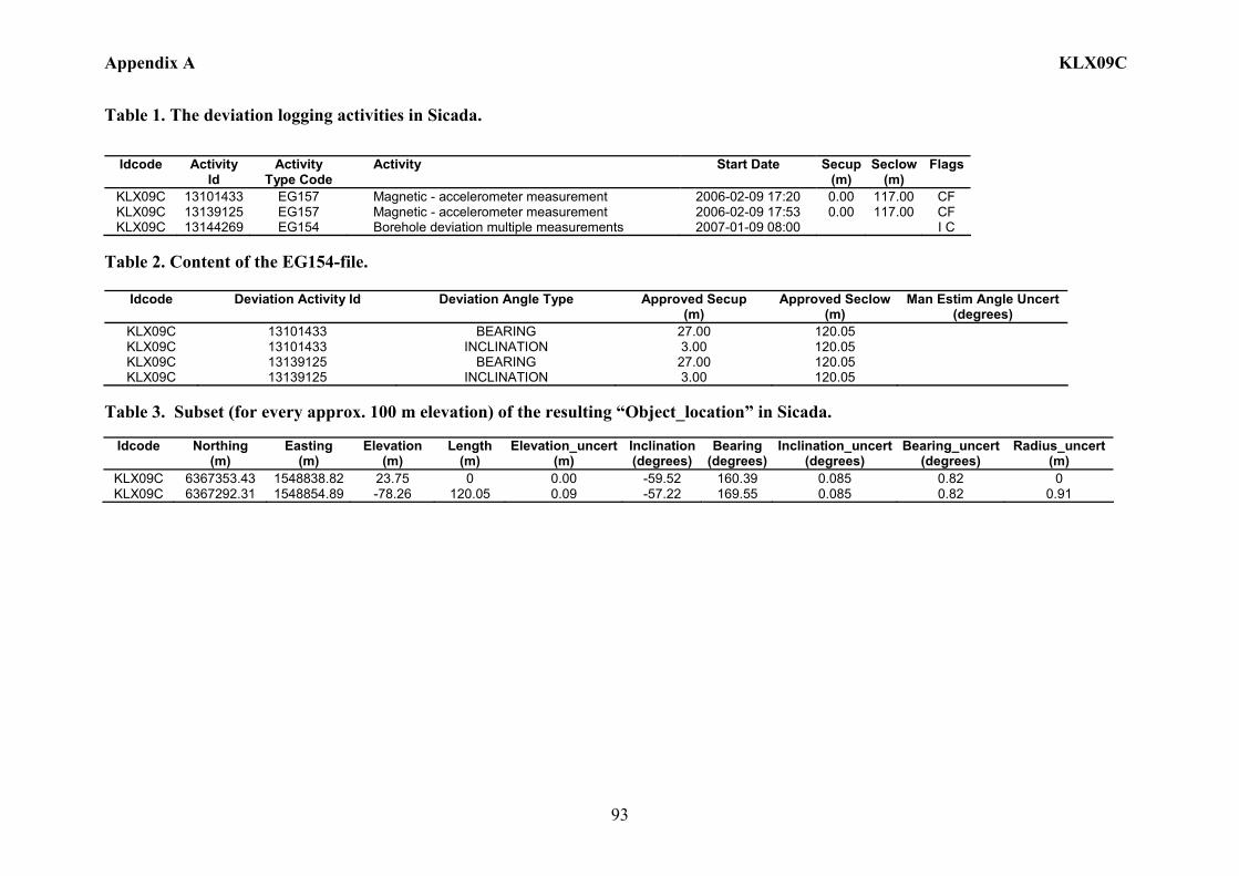
Appendix A KLX09C
93
Table 1. The deviation logging activities in Sicada.
Idcode Activity Id
Activity Type Code
Activity Start Date Secup(m)
Seclow(m)
Flags
KLX09C 13101433 EG157 Magnetic - accelerometer measurement 2006-02-09 17:20 0.00 117.00 CF KLX09C 13139125 EG157 Magnetic - accelerometer measurement 2006-02-09 17:53 0.00 117.00 CF KLX09C 13144269 EG154 Borehole deviation multiple measurements 2007-01-09 08:00 I C
Table 2. Content of the EG154-file.
Idcode Deviation Activity Id Deviation Angle Type Approved Secup (m)
Approved Seclow(m)
Man Estim Angle Uncert (degrees)
KLX09C 13101433 BEARING 27.00 120.05 KLX09C 13101433 INCLINATION 3.00 120.05 KLX09C 13139125 BEARING 27.00 120.05 KLX09C 13139125 INCLINATION 3.00 120.05
Table 3. Subset (for every approx. 100 m elevation) of the resulting “Object_location” in Sicada.
Idcode
Northing
(m) Easting
(m) Elevation
(m) Length
(m) Elevation_uncert
(m) Inclination (degrees)
Bearing (degrees)
Inclination_uncert(degrees)
Bearing_uncert(degrees)
Radius_uncert (m)
KLX09C 6367353.43 1548838.82 23.75 0 0.00 -59.52 160.39 0.085 0.82 0 KLX09C 6367292.31 1548854.89 -78.26 120.05 0.09 -57.22 169.55 0.085 0.82 0.91
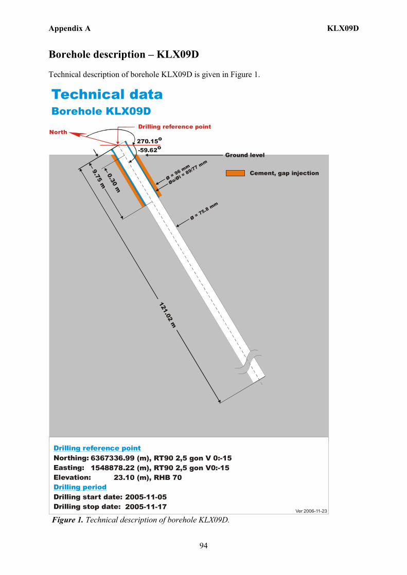
Appendix A KLX09D
94
Borehole description – KLX09D Technical description of borehole KLX09D is given in Figure 1.
6367336.99 (m),1548878.22 (m), 23.10 (m), 2005-11-05 2005-11-17
RT90 2,5 gon V0:-15 RHB 70
RT90 2,5 gon V 0:-15Northing:Easting:Elevation:
Drilling start date:Drilling stop date:
Drilling reference point
Drilling period
Cement, gap injection
Ver 2006-11-23
Technical dataBorehole KLX09D
North270.15o
-59.62o
Drilling reference point
Øo/= 89/77 m
m
Øi Ø = 96 mm
121.02 m
9.75 m0.30 m
Ø = 75.8 mm
Ground level
Figure 1. Technical description of borehole KLX09D.
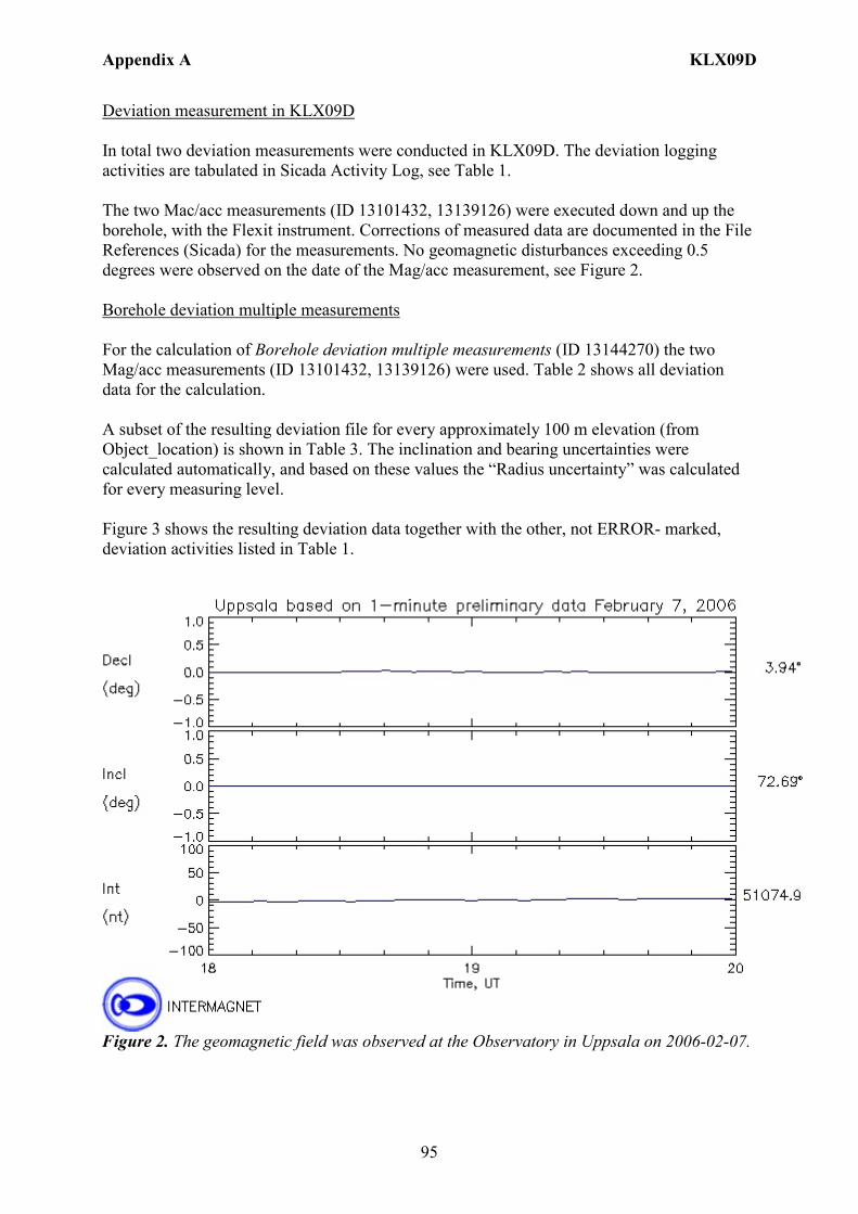
Appendix A KLX09D
95
Deviation measurement in KLX09D In total two deviation measurements were conducted in KLX09D. The deviation logging activities are tabulated in Sicada Activity Log, see Table 1. The two Mac/acc measurements (ID 13101432, 13139126) were executed down and up the borehole, with the Flexit instrument. Corrections of measured data are documented in the File References (Sicada) for the measurements. No geomagnetic disturbances exceeding 0.5 degrees were observed on the date of the Mag/acc measurement, see Figure 2. Borehole deviation multiple measurements For the calculation of Borehole deviation multiple measurements (ID 13144270) the two Mag/acc measurements (ID 13101432, 13139126) were used. Table 2 shows all deviation data for the calculation. A subset of the resulting deviation file for every approximately 100 m elevation (from Object_location) is shown in Table 3. The inclination and bearing uncertainties were calculated automatically, and based on these values the “Radius uncertainty” was calculated for every measuring level. Figure 3 shows the resulting deviation data together with the other, not ERROR- marked, deviation activities listed in Table 1.
Figure 2. The geomagnetic field was observed at the Observatory in Uppsala on 2006-02-07.
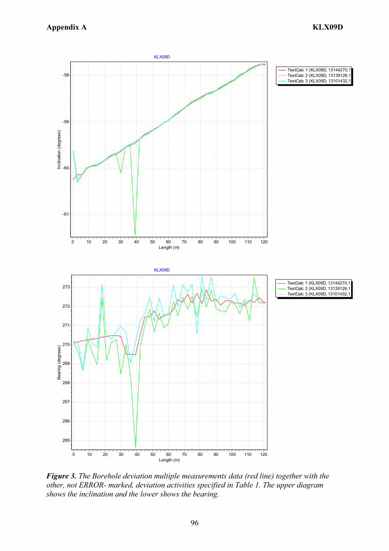
Appendix A KLX09D
96
TestCalc 1 (KLX09D, 13144270,1TestCalc 2 (KLX09D, 13139126,1TestCalc 3 (KLX09D, 13101432,1
KLX09D
Length (m)1201101009080706050403020100
Incl
inat
ion
(deg
rees
)
-58
-59
-60
-61
TestCalc 1 (KLX09D, 13144270,1TestCalc 2 (KLX09D, 13139126,1TestCalc 3 (KLX09D, 13101432,1
KLX09D
Length (m)1201101009080706050403020100
Bear
ing
(deg
rees
)
273
272
271
270
269
268
267
266
265
Figure 3. The Borehole deviation multiple measurements data (red line) together with the other, not ERROR- marked, deviation activities specified in Table 1. The upper diagram shows the inclination and the lower shows the bearing.
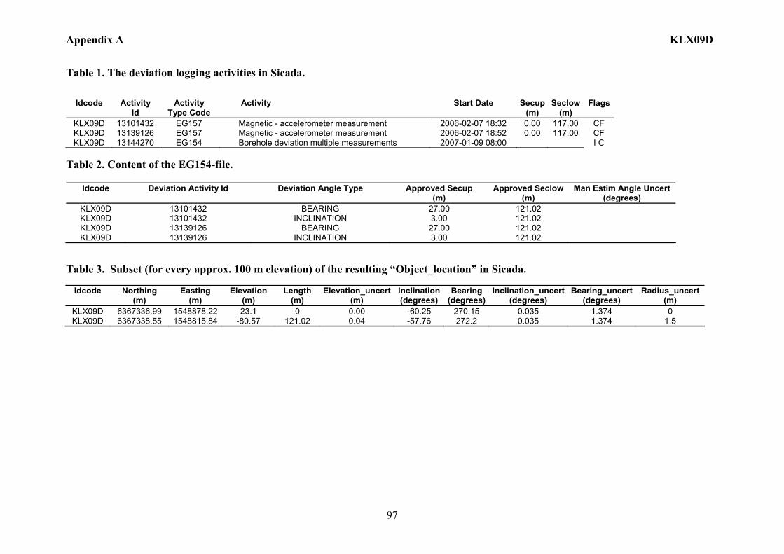
Appendix A KLX09D
97
Table 1. The deviation logging activities in Sicada.
Idcode Activity Id
Activity Type Code
Activity Start Date Secup(m)
Seclow(m)
Flags
KLX09D 13101432 EG157 Magnetic - accelerometer measurement 2006-02-07 18:32 0.00 117.00 CF KLX09D 13139126 EG157 Magnetic - accelerometer measurement 2006-02-07 18:52 0.00 117.00 CF KLX09D 13144270 EG154 Borehole deviation multiple measurements 2007-01-09 08:00 I C
Table 2. Content of the EG154-file.
Idcode Deviation Activity Id Deviation Angle Type Approved Secup (m)
Approved Seclow(m)
Man Estim Angle Uncert (degrees)
KLX09D 13101432 BEARING 27.00 121.02 KLX09D 13101432 INCLINATION 3.00 121.02 KLX09D 13139126 BEARING 27.00 121.02 KLX09D 13139126 INCLINATION 3.00 121.02
Table 3. Subset (for every approx. 100 m elevation) of the resulting “Object_location” in Sicada.
Idcode
Northing (m)
Easting (m)
Elevation (m)
Length (m)
Elevation_uncert(m)
Inclination (degrees)
Bearing (degrees)
Inclination_uncert(degrees)
Bearing_uncert(degrees)
Radius_uncert (m)
KLX09D 6367336.99 1548878.22 23.1 0 0.00 -60.25 270.15 0.035 1.374 0 KLX09D 6367338.55 1548815.84 -80.57 121.02 0.04 -57.76 272.2 0.035 1.374 1.5
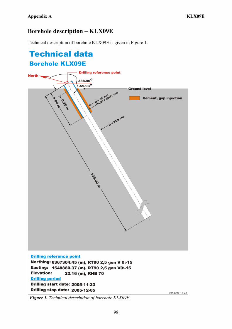
Appendix A KLX09E
98
Borehole description – KLX09E Technical description of borehole KLX09E is given in Figure 1.
6367304.45 (m),1548880.37 (m), 22.16 (m), 2005-11-23 2005-12-05
RT90 2,5 gon V0:-15 RHB 70
RT90 2,5 gon V 0:-15Northing:Easting:Elevation:
Drilling start date:Drilling stop date:
Drilling reference point
Drilling period
Cement, gap injection
Ver 2006-11-23
Technical dataBorehole KLX09E
North338.90o
-59.93o
Drilling reference point
Øo/= 89/77 m
m
Øi Ø = 96 mm
120.00 m
9.00 m0.30 m
Ø = 75.8 mm
Ground level
Figure 1. Technical description of borehole KLX09E.
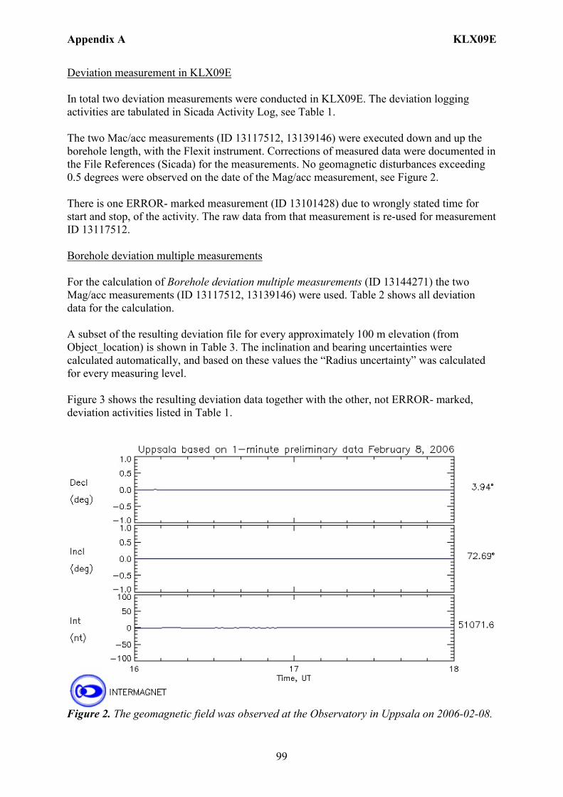
Appendix A KLX09E
99
Deviation measurement in KLX09E In total two deviation measurements were conducted in KLX09E. The deviation logging activities are tabulated in Sicada Activity Log, see Table 1. The two Mac/acc measurements (ID 13117512, 13139146) were executed down and up the borehole length, with the Flexit instrument. Corrections of measured data were documented in the File References (Sicada) for the measurements. No geomagnetic disturbances exceeding 0.5 degrees were observed on the date of the Mag/acc measurement, see Figure 2. There is one ERROR- marked measurement (ID 13101428) due to wrongly stated time for start and stop, of the activity. The raw data from that measurement is re-used for measurement ID 13117512. Borehole deviation multiple measurements For the calculation of Borehole deviation multiple measurements (ID 13144271) the two Mag/acc measurements (ID 13117512, 13139146) were used. Table 2 shows all deviation data for the calculation. A subset of the resulting deviation file for every approximately 100 m elevation (from Object_location) is shown in Table 3. The inclination and bearing uncertainties were calculated automatically, and based on these values the “Radius uncertainty” was calculated for every measuring level. Figure 3 shows the resulting deviation data together with the other, not ERROR- marked, deviation activities listed in Table 1.
Figure 2. The geomagnetic field was observed at the Observatory in Uppsala on 2006-02-08.
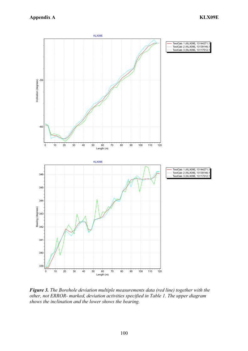
Appendix A KLX09E
100
TestCalc 1 (KLX09E, 13144271,1TestCalc 2 (KLX09E, 13139146,1TestCalc 3 (KLX09E, 13117512,1
KLX09E
Length (m)1201101009080706050403020100
Incl
inat
ion
(deg
rees
) -59
-60
TestCalc 1 (KLX09E, 13144271,1TestCalc 2 (KLX09E, 13139146,1TestCalc 3 (KLX09E, 13117512,1
KLX09E
Length (m)1201101009080706050403020100
Bear
ing
(deg
rees
)
346
345
344
343
342
341
340
339
Figure 3. The Borehole deviation multiple measurements data (red line) together with the other, not ERROR- marked, deviation activities specified in Table 1. The upper diagram shows the inclination and the lower shows the bearing.
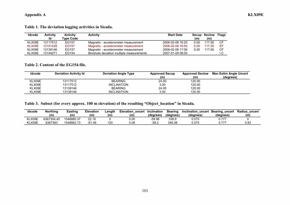
Appendix A KLX09E
101
Table 1. The deviation logging activities in Sicada.
Idcode Activity Id
Activity Type Code
Activity Start Date Secup(m)
Seclow(m)
Flags
KLX09E 13117512 EG157 Magnetic - accelerometer measurement 2006-02-08 16:20 0.00 117.00 CF KLX09E 13101428 EG157 Magnetic - accelerometer measurement 2006-02-08 16:50 0.00 117.00 EF KLX09E 13139146 EG157 Magnetic - accelerometer measurement 2006-02-08 17:06 0.00 117.00 CF KLX09E 13144271 EG154 Borehole deviation multiple measurements 2007-01-09 08:00 I C
Table 2. Content of the EG154-file.
Idcode Deviation Activity Id Deviation Angle Type Approved Secup (m)
Approved Seclow(m)
Man Estim Angle Uncert (degrees)
KLX09E 13117512 BEARING 24.00 120.00 KLX09E 13117512 INCLINATION 3.00 120.00 KLX09E 13139146 BEARING 24.00 120.00 KLX09E 13139146 INCLINATION 3.00 120.00
Table 3. Subset (for every approx. 100 m elevation) of the resulting “Object_location” in Sicada.
Idcode
Northing (m)
Easting (m)
Elevation (m)
Length (m)
Elevation_uncert(m)
Inclination (degrees)
Bearing (degrees)
Inclination_uncert(degrees)
Bearing_uncert(degrees)
Radius_uncert (m)
KLX09E 6367304.45 1548880.37 22.16 0 0.00 -59.96 338.9 0.075 0.777 0 KLX09E 6367363 1548862.73 -81.06 120 0.08 -58.2 346.08 0.075 0.777 0.83

Appendix A KLX09F
102
Borehole description – KLX09F Technical description of borehole KLX09F is given in Figure 1.
6367318.02 (m),1548817.27 (m), 19.57 (m), 2005-12-06 2006-01-06
RT90 2,5 gon V0:-15 RHB 70
RT90 2,5 gon V 0:-15Northing:Easting:Elevation:
Drilling start date:Drilling stop date:
Drilling reference point
Drilling period
Cement, gap injection
Ver 2006-11-23
Technical dataBorehole KLX09F
North90.67o
-59.14o
Drilling reference point
Øo/= 89/77 m
m
Øi Ø = 96 mm
152.30 m
9.00 m0.30 m
Ø = 75.7 mm
Ground level
Figure 1. Technical description of borehole KLX09F.

Appendix A KLX09F
103
Deviation measurement in KLX09F In total two deviation measurements were conducted in KLX09F. The deviation logging activities are tabulated in Sicada Activity Log, see Table 1. The two Mac/acc measurements (ID 13101429, 13139147) were executed down and up the borehole, with the Flexit instrument. Corrections of measured data were documented in the File References (Sicada) for the measurements. No geomagnetic disturbances exceeding 0.5 degrees were observed on the date of the Mag/acc measurement, see Figure 2. Borehole deviation multiple measurements For the calculation of Borehole deviation multiple measurements (ID 13144272) the two Mag/acc measurements (ID 13101429, 13139147) were used. Table 2 shows all deviation data for the calculation. A subset of the resulting deviation file for every approximately 100 m elevation (from Object_location) is shown in Table 3. The inclination and bearing uncertainties were calculated automatically, and based on these values the “Radius uncertainty” was calculated for every measuring level. Figure 3 shows the resulting deviation data together with the other, not ERROR- marked, deviation activities listed in Table 1.
Figure 2. The geomagnetic field was observed at the Observatory in Uppsala on 2006-02-09.

Appendix A KLX09F
104
TestCalc 1 (KLX09F, 13144272,1TestCalc 2 (KLX09F, 13139147,1TestCalc 3 (KLX09F, 13101429,1
KLX09F
Length (m)140120100806040200
Incl
inat
ion
(deg
rees
)
-57
-58
-59
TestCalc 1 (KLX09F, 13144272,1TestCalc 2 (KLX09F, 13139147,1TestCalc 3 (KLX09F, 13101429,1
KLX09F
Length (m)140120100806040200
Bear
ing
(deg
rees
)
102
101
100
99
98
97
96
95
94
93
92
91
Figure 3. The Borehole deviation multiple measurements data (red line) together with the other, not ERROR- marked, deviation activities specified in Table 1. The upper diagram shows the inclination and the lower shows the bearing.

Appendix A KLX09F
105
Table 1. The deviation logging activities in Sicada.
Idcode Activity Id
Activity Type Code
Activity Start Date Secup(m)
Seclow(m)
Flags
KLX09F 13101429 EG157 Magnetic - accelerometer measurement 2006-02-09 09:45 0.00 147.00 CF KLX09F 13139147 EG157 Magnetic - accelerometer measurement 2006-02-09 10:45 0.00 147.00 CF KLX09F 13144272 EG154 Borehole deviation multiple measurements 2007-01-09 08:00 I C
Table 2. Content of the EG154-file.
Idcode Deviation Activity Id Deviation Angle Type Approved Secup (m)
Approved Seclow(m)
Man Estim Angle Uncert (degrees)
KLX09F 13101429 BEARING 24.00 152.30 KLX09F 13101429 INCLINATION 3.00 152.30 KLX09F 13139147 BEARING 24.00 152.30 KLX09F 13139147 INCLINATION 3.00 152.30
Table 3. Subset (for every approx. 100 m elevation) of the resulting “Object_location” in Sicada.
Idcode
Northing (m)
Easting (m)
Elevation (m)
Length (m)
Elevation_uncert(m)
Inclination (degrees)
Bearing (degrees)
Inclination_uncert(degrees)
Bearing_uncert(degrees)
Radius_uncert (m)
KLX09F 6367318.02 1548817.26 19.57 0 0.00 -59.74 90.67 0.03 0.65 0 KLX09F 6367308.38 1548896.64 -109.96 152.3 0.04 -56.63 101.39 0.03 0.65 0.91
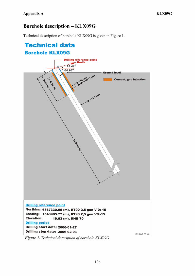
Appendix A KLX09G
106
Borehole description – KLX09G Technical description of borehole KLX09G is given in Figure 1.
6367330.09 (m),1548905.77 (m), 19.63 (m), 2006-01-27 2006-02-03
RT90 2,5 gon V0:-15 RHB 70
RT90 2,5 gon V 0:-15Northing:Easting:Elevation:
Drilling start date:Drilling stop date:
Drilling reference point
Drilling period
Cement, gap injection
Ver 2006-11-23
Technical dataBorehole KLX09G
North85.41o
-60.96o
Drilling reference point
Øo/= 89/77 mm
Øi Ø = 96 mm
100.10 m
9.30 m0.30 m
Ø = 75.7 mm
Ground level
Figure 1. Technical description of borehole KLX09G.

Appendix A KLX09G
107
Deviation measurement in KLX09G In total two deviation measurements were conducted in KLX09G. The deviation logging activities are tabulated in Sicada Activity Log, see Table 1. The two Mac/acc measurements (ID 13101431, 13139174) were executed down and up the borehole, with the Flexit instrument. Corrections of measured data were documented in the File References (Sicada) for the measurements. No geomagnetic disturbances exceeding 0.5 degrees were observed on the date of the Mag/acc measuring, see Figure 2. Borehole deviation multiple measurements For the calculation of Borehole deviation multiple measurements (ID 13144273) the two Mag/acc measurements (ID 13101431, 13139174) were used. Table 2 shows all deviation data for the calculation. A subset of the resulting deviation file for every approximately 100 m elevation (from Object_location) is shown in Table 3. The inclination and bearing uncertainties were calculated automatically, and based on these values the “Radius uncertainty” was calculated for every measuring level. Figure 3 shows the resulting deviation data together with the other, not ERROR- marked, deviation activities listed in Table 1.
Figure 2. The geomagnetic field was observed at the Observatory in Uppsala on 2006-02-07.
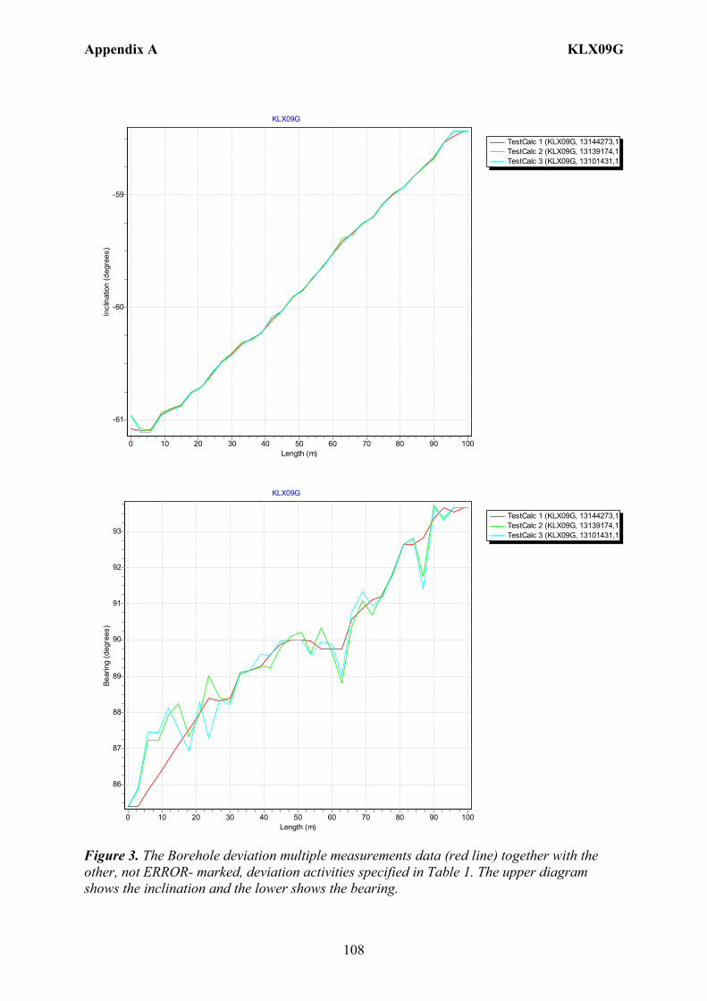
Appendix A KLX09G
108
TestCalc 1 (KLX09G, 13144273,1TestCalc 2 (KLX09G, 13139174,1TestCalc 3 (KLX09G, 13101431,1
KLX09G
Length (m)1009080706050403020100
Incl
inat
ion
(deg
rees
)
-59
-60
-61
TestCalc 1 (KLX09G, 13144273,1TestCalc 2 (KLX09G, 13139174,1TestCalc 3 (KLX09G, 13101431,1
KLX09G
Length (m)1009080706050403020100
Bear
ing
(deg
rees
)
93
92
91
90
89
88
87
86
Figure 3. The Borehole deviation multiple measurements data (red line) together with the other, not ERROR- marked, deviation activities specified in Table 1. The upper diagram shows the inclination and the lower shows the bearing.
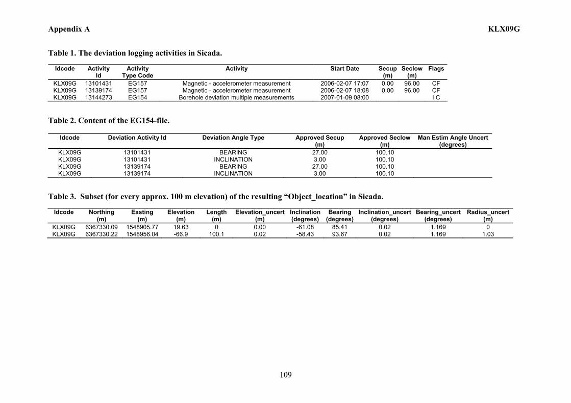
Appendix A KLX09G
109
Table 1. The deviation logging activities in Sicada.
Idcode Activity Id
Activity Type Code
Activity Start Date Secup(m)
Seclow(m)
Flags
KLX09G 13101431 EG157 Magnetic - accelerometer measurement 2006-02-07 17:07 0.00 96.00 CF KLX09G 13139174 EG157 Magnetic - accelerometer measurement 2006-02-07 18:08 0.00 96.00 CF KLX09G 13144273 EG154 Borehole deviation multiple measurements 2007-01-09 08:00 I C
Table 2. Content of the EG154-file.
Idcode Deviation Activity Id Deviation Angle Type Approved Secup (m)
Approved Seclow(m)
Man Estim Angle Uncert (degrees)
KLX09G 13101431 BEARING 27.00 100.10 KLX09G 13101431 INCLINATION 3.00 100.10 KLX09G 13139174 BEARING 27.00 100.10 KLX09G 13139174 INCLINATION 3.00 100.10
Table 3. Subset (for every approx. 100 m elevation) of the resulting “Object_location” in Sicada.
Idcode
Northing (m)
Easting (m)
Elevation (m)
Length (m)
Elevation_uncert(m)
Inclination (degrees)
Bearing (degrees)
Inclination_uncert(degrees)
Bearing_uncert(degrees)
Radius_uncert (m)
KLX09G 6367330.09 1548905.77 19.63 0 0.00 -61.08 85.41 0.02 1.169 0 KLX09G 6367330.22 1548956.04 -66.9 100.1 0.02 -58.43 93.67 0.02 1.169 1.03
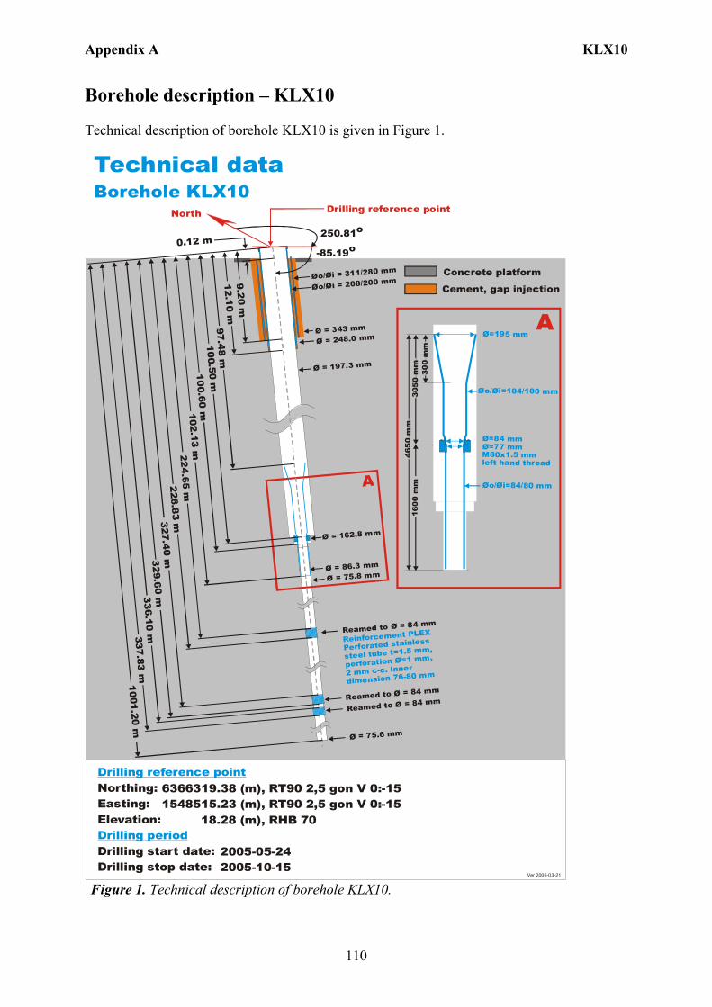
Appendix A KLX10
110
Borehole description – KLX10 Technical description of borehole KLX10 is given in Figure 1. Technical dataBorehole KLX10
6366319.38 (m),1548515.23 (m), 18.28 (m), 2005-05-24 2005-10-15
RT90 2,5 gon V 0:-15 RHB 70
RT90 2,5 gon V 0:-15Northing:Easting:Elevation:
Drilling start date:Drilling stop date:
Drilling reference point
Drilling period
North
250.81o
-85.19o
Drilling reference point
Ø=195 mm
Øo/ =104/100 mmØi
Ø=84 mmØ=77 mm M80x1.5 mm left hand thread
Øo/ =84/80 mmØi
300
mm
305
0 m
m46
50
mm
1 60
0 m
m
A
Ø = 197.3 mm
Øo/ = 311/280 mmØi
Øo/ = 208/200 mmØi
Ø = 75.8 mm
A
0.12 m
97.48 m
102 .13 m
Ø = 343 mm
100.60 m
1001.2 0 m
Ø = 162.8 mm
Ø = 86.3 mm
Reinforcement PLEX
Perforated stainless
steel tube t=1.5 mm,
perforation =1 mm,
2 mm c-c. Inner
dimension 76-80 mm
Ø
Cement, gap injection
Concrete platform
Ver 2006-03-21
9. 20 m12 .10 m
Ø = 248.0 mm100.50 m
Ø = 75.6 mm
Reamed to Ø = 84 mm
337.83 m336.10 m
329.6 0 m327.4 0 m
Reamed to Ø = 84 mm
Reamed to Ø = 84 mm
226.83 m
Figure 1. Technical description of borehole KLX10.
Appendix A KLX10
111
Deviation measurement in KLX10 In total three deviation measurements were conducted in KLX10. The deviation logging activities are tabulated in Sicada Activity Log, see Table 1. The Maxibor measurement was executed with the instrument mounted inside a barrel which was joined to the lower end of the drill string. The starting values for the Maxibor measurements in KLX10 were measured with the Total station aiming on a prism, above and lined up with the TOC. A later calculation gave the values at borehole length 3.00 m which was used as start values (bearing and inclination) for the Maxibor measurements. When the calculation of the Maxibor measurement was done, the values for borehole length 0.00 m were added. See document (ID 1037594 Documentum). The two Maxibor measurements (ID 13094371, 13139221) were executed down and up the borehole. The Mac/acc measurement (ID 13119847) was executed down in the borehole, with the Flexit instrument. Corrections of measured data were documented in the File References (Sicada) for the measurements. No geomagnetic disturbances exceeding 0.5 degrees were observed on the date of the Mag/acc measurement, see Figure 2. There is one ERROR- marked measurement, mag/acc (ID 13099955) which was bug reported (Bug 1819) due to wrongly correction for magnetic declination and meridian convergence. But the raw data from that measurement was re-used, without correction for magnetic declination and meridian convergence, to calculate the correct measurement (ID 13119847). Borehole deviation multiple measurements For the calculation of Borehole deviation multiple measurements (ID 13144298) the two Maxibor measurements (ID 13094371, 13139221) and the Mag/acc measurement (ID 13119847) were used. The strategy used in selecting the activities is in agreement with the general strategy (Section 4.4.2). Table 2 shows all deviation data for the calculation. A subset of the resulting deviation file for every approximately 100 m elevation (from Object_location) is shown in Table 3. The inclination and bearing uncertainties were calculated automatically, and based on these values the “Radius uncertainty” was calculated for every measuring level. Figure 3 shows the resulting deviation data together with the other, not ERROR- marked, deviation activities listed in Table 1.
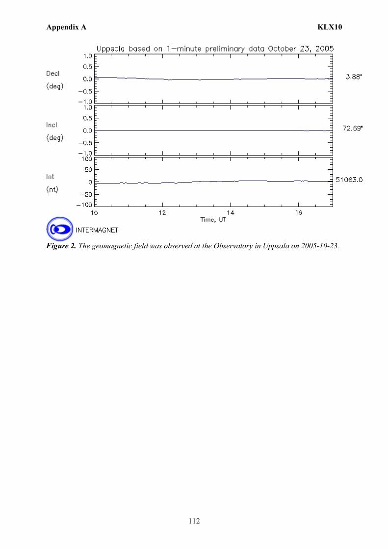
Appendix A KLX10
112
Figure 2. The geomagnetic field was observed at the Observatory in Uppsala on 2005-10-23.
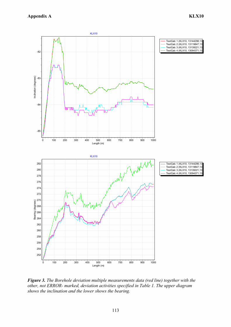
Appendix A KLX10
113
TestCalc 1 (KLX10, 13144298,13TestCalc 2 (KLX10, 13119847,13TestCalc 3 (KLX10, 13139221,13TestCalc 4 (KLX10, 13094371,13
KLX10
Length (m)10009008007006005004003002001000
Incl
inat
ion
(deg
rees
)
-82
-83
-84
-85
TestCalc 1 (KLX10, 13144298,13TestCalc 2 (KLX10, 13119847,13TestCalc 3 (KLX10, 13139221,13TestCalc 4 (KLX10, 13094371,13
KLX10
Length (m)10009008007006005004003002001000
Bear
ing
(deg
rees
)
282
280
278
276
274
272
270
268
266
264
262
260
258
256
254
252
Figure 3. The Borehole deviation multiple measurements data (red line) together with the other, not ERROR- marked, deviation activities specified in Table 1. The upper diagram shows the inclination and the lower shows the bearing.
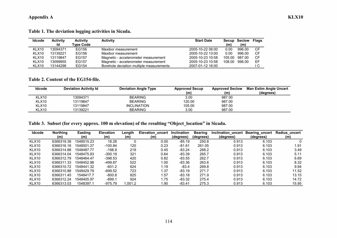
Appendix A KLX10
114
Table 1. The deviation logging activities in Sicada.
Idcode Activity Id
Activity Type Code
Activity Start Date Secup(m)
Seclow(m)
Flags
KLX10 13094371 EG156 Maxibor measurement 2005-10-22 06:00 0.00 996.00 CF KLX10 13139221 EG156 Maxibor measurement 2005-10-22 13:00 0.00 996.00 CF KLX10 13119847 EG157 Magnetic - accelerometer measurement 2005-10-23 10:58 105.00 987.00 CF KLX10 13099955 EG157 Magnetic - accelerometer measurement 2005-10-23 10:58 108.00 996.00 EF KLX10 13144298 EG154 Borehole deviation multiple measurements 2007-01-12 16:00 I C
Table 2. Content of the EG154-file.
Idcode Deviation Activity Id Deviation Angle Type Approved Secup (m)
Approved Seclow(m)
Man Estim Angle Uncert (degrees)
KLX10 13094371 BEARING 3.00 987.00 KLX10 13119847 BEARING 120.00 987.00 KLX10 13119847 INCLINATION 105.00 987.00 KLX10 13139221 BEARING 3.00 987.00
Table 3. Subset (for every approx. 100 m elevation) of the resulting “Object_location” in Sicada.
Idcode
Northing
(m) Easting
(m) Elevation
(m) Length
(m) Elevation_uncert
(m) Inclination (degrees)
Bearing (degrees)
Inclination_uncert(degrees)
Bearing_uncert(degrees)
Radius_uncert (m)
KLX10 6366319.38 1548515.23 18.28 0 0.00 -85.19 250.8 0.913 6.103 0 KLX10 6366316.16 1548501.27 -100.84 120 0.23 -81.61 261.05 0.913 6.103 1.91 KLX10 6366314.88 1548487.77 -198.9 219 0.45 -83.24 268.2 0.913 6.103 3.49 KLX10 6366314.04 1548475.83 -300.19 321 0.64 -83.39 265.7 0.913 6.103 5.11 KLX10 6366312.79 1548464.47 -398.53 420 0.82 -83.55 262.7 0.913 6.103 6.69 KLX10 6366311.33 1548452.98 -499.87 522 1.00 -83.36 263.6 0.913 6.103 8.32 KLX10 6366310.72 1548441.32 -601.2 624 1.19 -83.4 269.8 0.913 6.103 9.94 KLX10 6366310.88 1548429.79 -699.52 723 1.37 -83.19 271.7 0.913 6.103 11.52 KLX10 6366311.45 1548417.7 -800.8 825 1.57 -83.18 271.9 0.913 6.103 13.15 KLX10 6366312.24 1548405.97 -899.1 924 1.75 -83.32 275.4 0.913 6.103 14.72 KLX10 6366313.03 1548397.1 -975.79 1,001.2 1.90 -83.41 275.3 0.913 6.103 15.95
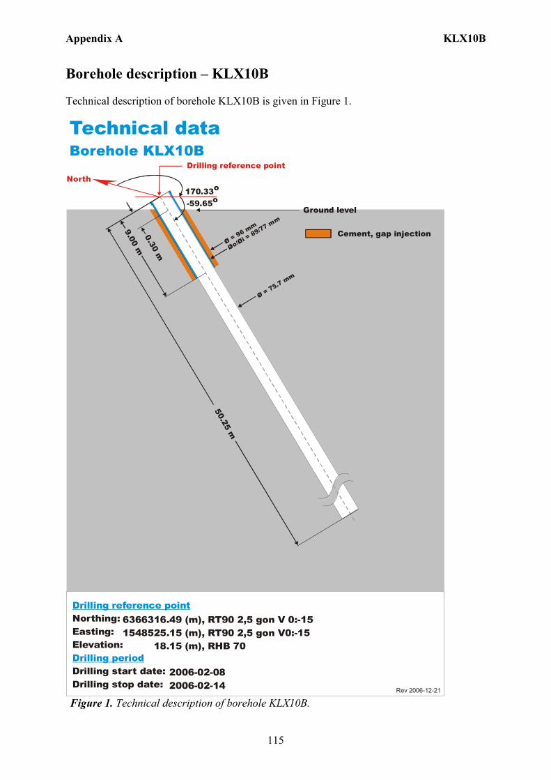
Appendix A KLX10B
115
Borehole description – KLX10B Technical description of borehole KLX10B is given in Figure 1.
6366316.49 (m),1548525.15 (m), 18.15 (m), 2006-02-08 2006-02-14
RT90 2,5 gon V0:-15 RHB 70
RT90 2,5 gon V 0:-15Northing:Easting:Elevation:
Drilling start date:Drilling stop date:
Drilling reference point
Drilling period
Cement, gap injection
Rev 2006-12-21
Technical dataBorehole KLX10B
170.33o
-59.65o
Drilling reference point
Øo/= 89/77 m
m
Øi Ø = 96 mm
50.25 m
9.00 m0.30 m
Ø = 75.7 mm
Ground level
North
Figure 1. Technical description of borehole KLX10B.
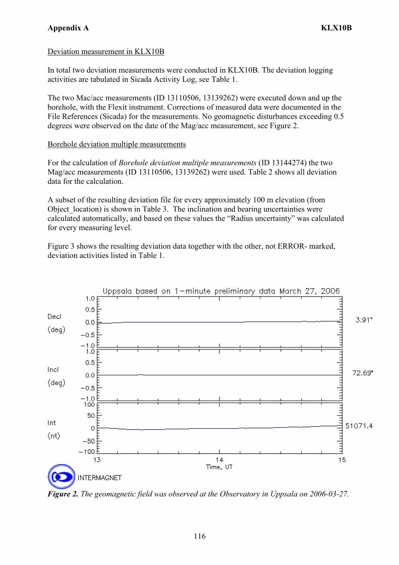
Appendix A KLX10B
116
Deviation measurement in KLX10B In total two deviation measurements were conducted in KLX10B. The deviation logging activities are tabulated in Sicada Activity Log, see Table 1. The two Mac/acc measurements (ID 13110506, 13139262) were executed down and up the borehole, with the Flexit instrument. Corrections of measured data were documented in the File References (Sicada) for the measurements. No geomagnetic disturbances exceeding 0.5 degrees were observed on the date of the Mag/acc measurement, see Figure 2. Borehole deviation multiple measurements For the calculation of Borehole deviation multiple measurements (ID 13144274) the two Mag/acc measurements (ID 13110506, 13139262) were used. Table 2 shows all deviation data for the calculation. A subset of the resulting deviation file for every approximately 100 m elevation (from Object_location) is shown in Table 3. The inclination and bearing uncertainties were calculated automatically, and based on these values the “Radius uncertainty” was calculated for every measuring level. Figure 3 shows the resulting deviation data together with the other, not ERROR- marked, deviation activities listed in Table 1.
Figure 2. The geomagnetic field was observed at the Observatory in Uppsala on 2006-03-27.
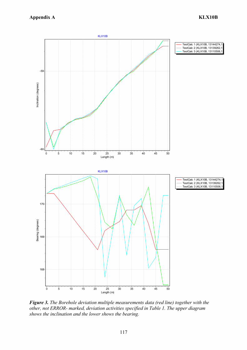
Appendix A KLX10B
117
TestCalc 1 (KLX10B, 13144274,1TestCalc 2 (KLX10B, 13139262,1TestCalc 3 (KLX10B, 13110506,1
KLX10B
Length (m)50454035302520151050
Incl
inat
ion
(deg
rees
)
-59
-60
TestCalc 1 (KLX10B, 13144274,1TestCalc 2 (KLX10B, 13139262,1TestCalc 3 (KLX10B, 13110506,1
KLX10B
Length (m)50454035302520151050
Bear
ing
(deg
rees
)
170
169
168
Figure 3. The Borehole deviation multiple measurements data (red line) together with the other, not ERROR- marked, deviation activities specified in Table 1. The upper diagram shows the inclination and the lower shows the bearing.

Appendix A KLX10B
118
Table 1. The deviation logging activities in Sicada.
Idcode Activity Id
Activity Type Code
Activity Start Date Secup(m)
Seclow(m)
Flags
KLX10B 13110506 EG157 Magnetic - accelerometer measurement 2006-03-27 13:34 0.00 48.00 CF KLX10B 13139262 EG157 Magnetic - accelerometer measurement 2006-03-27 14:02 0.00 48.00 CF KLX10B 13144274 EG154 Borehole deviation multiple measurements 2007-01-09 08:00 I C
Table 2. Content of the EG154-file.
Idcode Deviation Activity Id Deviation Angle Type Approved Secup (m)
Approved Seclow(m)
Man Estim Angle Uncert (degrees)
KLX10B 13110506 BEARING 24.00 50.25 KLX10B 13110506 INCLINATION 3.00 50.25 KLX10B 13139262 BEARING 24.00 50.25 KLX10B 13139262 INCLINATION 3.00 50.25
Table 3. Subset (for every approx. 100 m elevation) of the resulting “Object_location” in Sicada.
Idcode
Northing (m)
Easting (m)
Elevation (m)
Length (m)
Elevation_uncert(m)
Inclination (degrees)
Bearing (degrees)
Inclination_uncert(degrees)
Bearing_uncert(degrees)
Radius_uncert (m)
KLX10B 6366316.49 1548525.15 18.15 0 0.00 -59.97 170.32 0.066 1.638 0 KLX10B 6366291.26 1548529.87 -25.05 50.25 0.03 -58.68 168.62 0.066 1.638 0.73
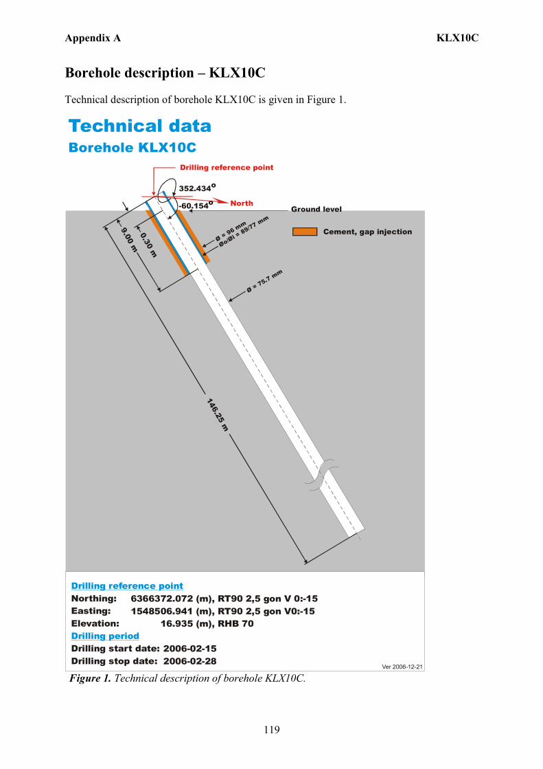
Appendix A KLX10C
119
Borehole description – KLX10C Technical description of borehole KLX10C is given in Figure 1.
6366372.072 (m), 1548506.941 (m), 16.935 (m), 2006-02-15 2006-02-28
RT90 2,5 gon V0:-15 RHB 70
RT90 2,5 gon V 0:-15Northing:Easting:Elevation:
Drilling start date:Drilling stop date:
Drilling reference point
Drilling period
Cement, gap injection
Ver 2006-12-21
Technical dataBorehole KLX10C
North
352.434o
Drilling reference point
Øo/= 89/77 mm
Øi Ø = 96 mm
146.25 m
9.00 m0.30 m
Ø = 75.7 mm
Ground level-60.154o
Figure 1. Technical description of borehole KLX10C.
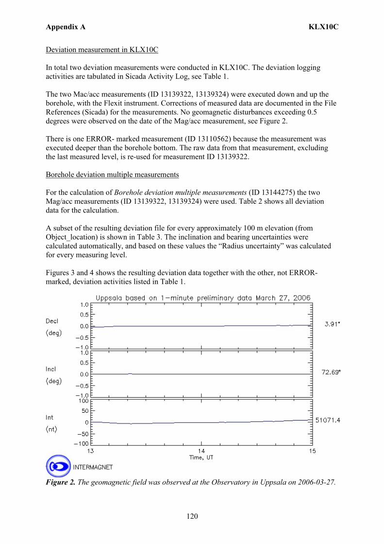
Appendix A KLX10C
120
Deviation measurement in KLX10C In total two deviation measurements were conducted in KLX10C. The deviation logging activities are tabulated in Sicada Activity Log, see Table 1. The two Mac/acc measurements (ID 13139322, 13139324) were executed down and up the borehole, with the Flexit instrument. Corrections of measured data are documented in the File References (Sicada) for the measurements. No geomagnetic disturbances exceeding 0.5 degrees were observed on the date of the Mag/acc measurement, see Figure 2. There is one ERROR- marked measurement (ID 13110562) because the measurement was executed deeper than the borehole bottom. The raw data from that measurement, excluding the last measured level, is re-used for measurement ID 13139322. Borehole deviation multiple measurements For the calculation of Borehole deviation multiple measurements (ID 13144275) the two Mag/acc measurements (ID 13139322, 13139324) were used. Table 2 shows all deviation data for the calculation. A subset of the resulting deviation file for every approximately 100 m elevation (from Object_location) is shown in Table 3. The inclination and bearing uncertainties were calculated automatically, and based on these values the “Radius uncertainty” was calculated for every measuring level. Figures 3 and 4 shows the resulting deviation data together with the other, not ERROR- marked, deviation activities listed in Table 1.
Figure 2. The geomagnetic field was observed at the Observatory in Uppsala on 2006-03-27.
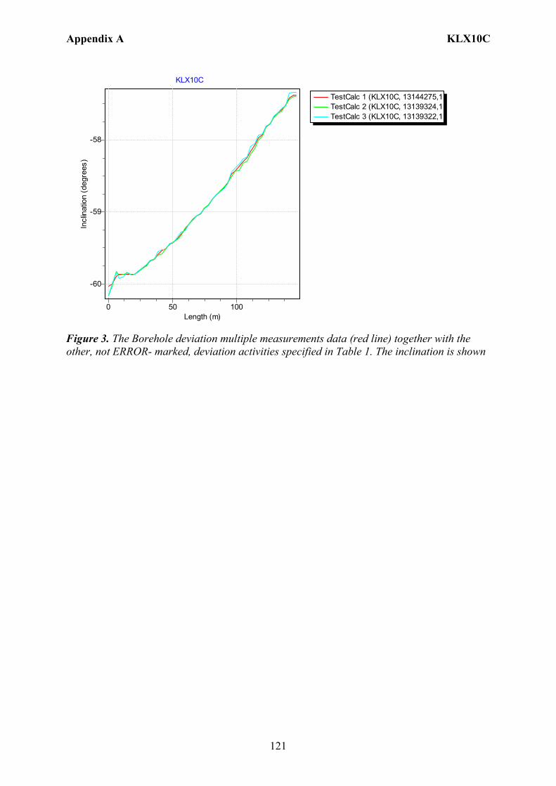
Appendix A KLX10C
121
TestCalc 1 (KLX10C, 13144275,1TestCalc 2 (KLX10C, 13139324,1TestCalc 3 (KLX10C, 13139322,1
KLX10C
Length (m)100500
Incl
inat
ion
(deg
rees
)
-58
-59
-60
Figure 3. The Borehole deviation multiple measurements data (red line) together with the other, not ERROR- marked, deviation activities specified in Table 1. The inclination is shown
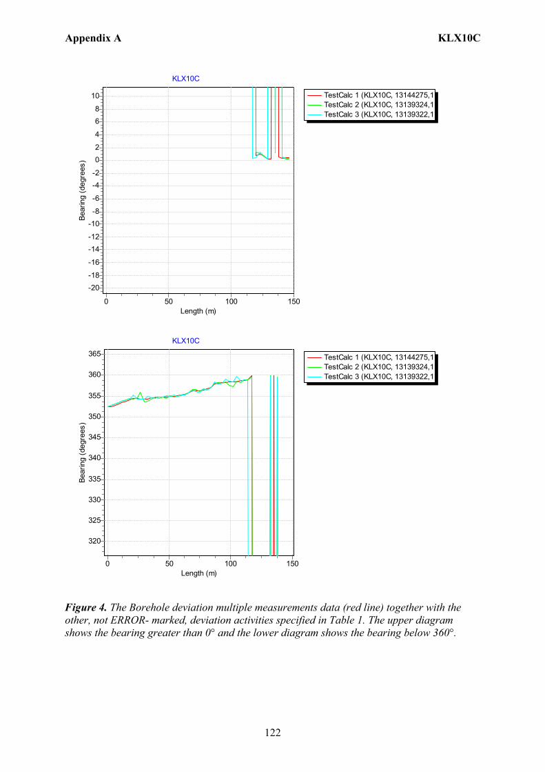
Appendix A KLX10C
122
TestCalc 1 (KLX10C, 13144275,1TestCalc 2 (KLX10C, 13139324,1TestCalc 3 (KLX10C, 13139322,1
KLX10C
Length (m)150100500
Bear
ing
(deg
rees
)
10
86
4
20
-2-4
-6
-8-10
-12-14
-16
-18-20
TestCalc 1 (KLX10C, 13144275,1TestCalc 2 (KLX10C, 13139324,1TestCalc 3 (KLX10C, 13139322,1
KLX10C
Length (m)150100500
Bear
ing
(deg
rees
)
365
360
355
350
345
340
335
330
325
320
Figure 4. The Borehole deviation multiple measurements data (red line) together with the other, not ERROR- marked, deviation activities specified in Table 1. The upper diagram shows the bearing greater than 0° and the lower diagram shows the bearing below 360°.
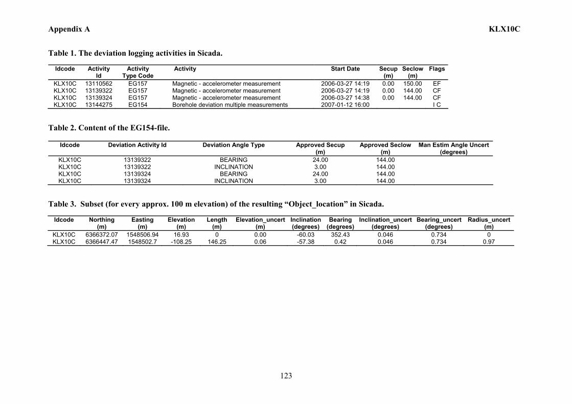
Appendix A KLX10C
123
Table 1. The deviation logging activities in Sicada.
Idcode Activity Id
Activity Type Code
Activity Start Date Secup(m)
Seclow(m)
Flags
KLX10C 13110562 EG157 Magnetic - accelerometer measurement 2006-03-27 14:19 0.00 150.00 EF KLX10C 13139322 EG157 Magnetic - accelerometer measurement 2006-03-27 14:19 0.00 144.00 CF KLX10C 13139324 EG157 Magnetic - accelerometer measurement 2006-03-27 14:38 0.00 144.00 CF KLX10C 13144275 EG154 Borehole deviation multiple measurements 2007-01-12 16:00 I C
Table 2. Content of the EG154-file.
Idcode Deviation Activity Id Deviation Angle Type Approved Secup (m)
Approved Seclow(m)
Man Estim Angle Uncert (degrees)
KLX10C 13139322 BEARING 24.00 144.00 KLX10C 13139322 INCLINATION 3.00 144.00 KLX10C 13139324 BEARING 24.00 144.00 KLX10C 13139324 INCLINATION 3.00 144.00
Table 3. Subset (for every approx. 100 m elevation) of the resulting “Object_location” in Sicada.
Idcode
Northing (m)
Easting (m)
Elevation (m)
Length (m)
Elevation_uncert(m)
Inclination (degrees)
Bearing (degrees)
Inclination_uncert(degrees)
Bearing_uncert(degrees)
Radius_uncert (m)
KLX10C 6366372.07 1548506.94 16.93 0 0.00 -60.03 352.43 0.046 0.734 0 KLX10C 6366447.47 1548502.7 -108.25 146.25 0.06 -57.38 0.42 0.046 0.734 0.97
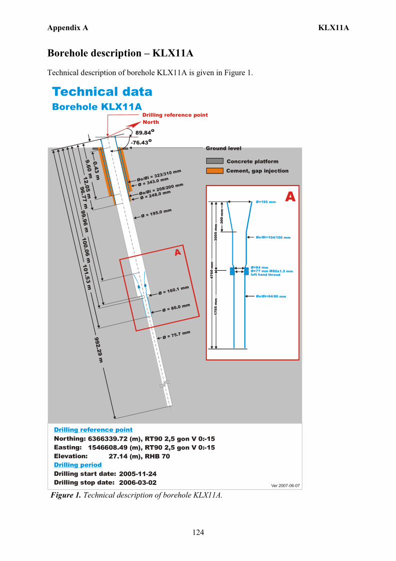
Appendix A KLX11A
124
Borehole description – KLX11A Technical description of borehole KLX11A is given in Figure 1.
6366339.72 (m),1546608.49 (m), 27.14 (m), 2005-11-24 2006-03-02
RT90 2,5 gon V 0:-15 RHB 70
RT90 2,5 gon V 0:-15Northing:Easting:Elevation:
Drilling start date:Drilling stop date:
Drilling reference point
Drilling period
Cement, gap injection
Concrete platform
Ver 2007-06-07
Technical dataBorehole KLX11A
Drilling reference point
Ground level
Ø = 195.0 mm
Øo/ = 323/310 mm
Øi
Øo/ = 208/200 mm
Øi
Ø = 75.7 mm
A
0.43 m
9.60 m
Ø = 343.0 mm
100.06 m96.77 m
992.29 mØ = 160.1 mm
Ø = 86.0 mm
99.96 m101.53 m
12.05 m
Ø = 248.0 mm
North
89.84o
-76.43o
Ø=195 mm
Øo/ =104/100 mmØi
Ø=84 mmØ=77 mm M80x1.5 mm left hand thread
Øo/ =84/80 mmØi
300
mm
3005
mm
4760
mm
1755
mm
A
Figure 1. Technical description of borehole KLX11A.
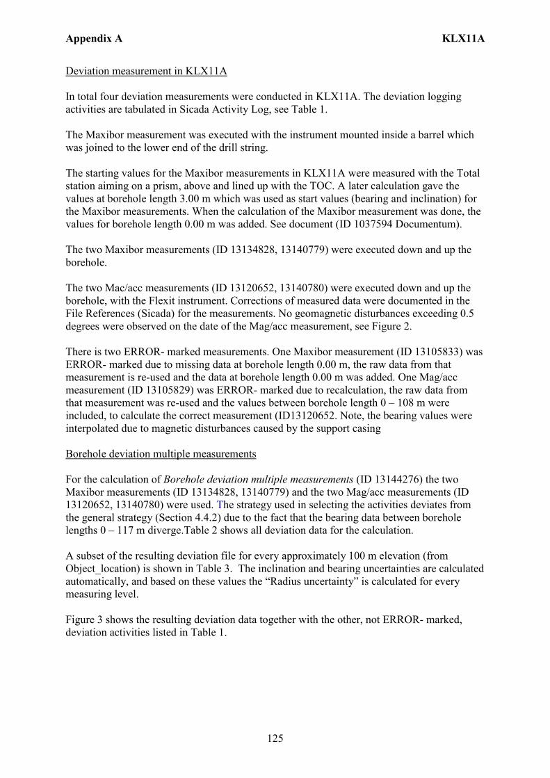
Appendix A KLX11A
125
Deviation measurement in KLX11A In total four deviation measurements were conducted in KLX11A. The deviation logging activities are tabulated in Sicada Activity Log, see Table 1. The Maxibor measurement was executed with the instrument mounted inside a barrel which was joined to the lower end of the drill string. The starting values for the Maxibor measurements in KLX11A were measured with the Total station aiming on a prism, above and lined up with the TOC. A later calculation gave the values at borehole length 3.00 m which was used as start values (bearing and inclination) for the Maxibor measurements. When the calculation of the Maxibor measurement was done, the values for borehole length 0.00 m was added. See document (ID 1037594 Documentum). The two Maxibor measurements (ID 13134828, 13140779) were executed down and up the borehole. The two Mac/acc measurements (ID 13120652, 13140780) were executed down and up the borehole, with the Flexit instrument. Corrections of measured data were documented in the File References (Sicada) for the measurements. No geomagnetic disturbances exceeding 0.5 degrees were observed on the date of the Mag/acc measurement, see Figure 2. There is two ERROR- marked measurements. One Maxibor measurement (ID 13105833) was ERROR- marked due to missing data at borehole length 0.00 m, the raw data from that measurement is re-used and the data at borehole length 0.00 m was added. One Mag/acc measurement (ID 13105829) was ERROR- marked due to recalculation, the raw data from that measurement was re-used and the values between borehole length 0 – 108 m were included, to calculate the correct measurement (ID13120652. Note, the bearing values were interpolated due to magnetic disturbances caused by the support casing Borehole deviation multiple measurements For the calculation of Borehole deviation multiple measurements (ID 13144276) the two Maxibor measurements (ID 13134828, 13140779) and the two Mag/acc measurements (ID 13120652, 13140780) were used. The strategy used in selecting the activities deviates from the general strategy (Section 4.4.2) due to the fact that the bearing data between borehole lengths 0 – 117 m diverge.Table 2 shows all deviation data for the calculation. A subset of the resulting deviation file for every approximately 100 m elevation (from Object_location) is shown in Table 3. The inclination and bearing uncertainties are calculated automatically, and based on these values the “Radius uncertainty” is calculated for every measuring level. Figure 3 shows the resulting deviation data together with the other, not ERROR- marked, deviation activities listed in Table 1.
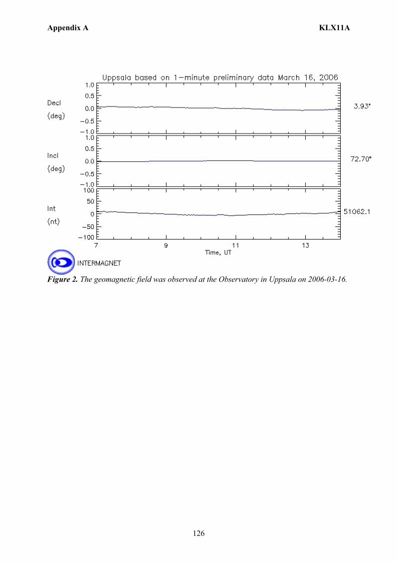
Appendix A KLX11A
126
Figure 2. The geomagnetic field was observed at the Observatory in Uppsala on 2006-03-16.
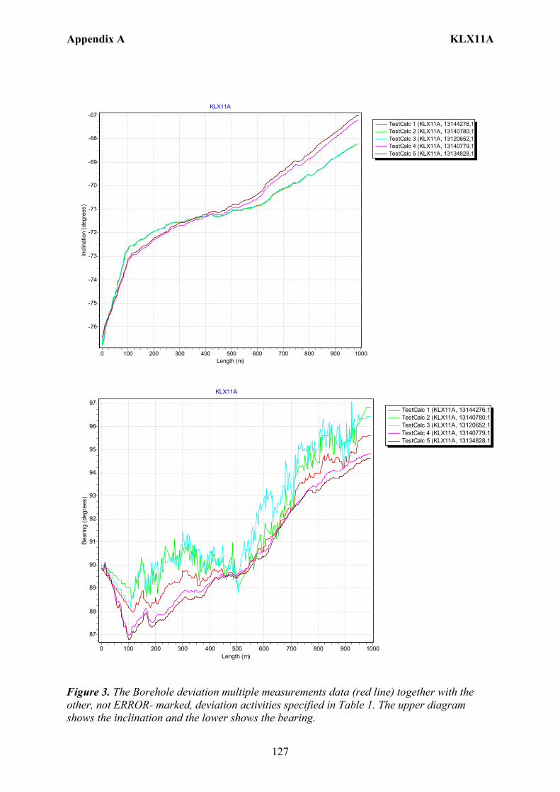
Appendix A KLX11A
127
TestCalc 1 (KLX11A, 13144276,1TestCalc 2 (KLX11A, 13140780,1TestCalc 3 (KLX11A, 13120652,1TestCalc 4 (KLX11A, 13140779,1TestCalc 5 (KLX11A, 13134828,1
KLX11A
Length (m)10009008007006005004003002001000
Incl
inat
ion
(deg
rees
)
-67
-68
-69
-70
-71
-72
-73
-74
-75
-76
TestCalc 1 (KLX11A, 13144276,1TestCalc 2 (KLX11A, 13140780,1TestCalc 3 (KLX11A, 13120652,1TestCalc 4 (KLX11A, 13140779,1TestCalc 5 (KLX11A, 13134828,1
KLX11A
Length (m)10009008007006005004003002001000
Bear
ing
(deg
rees
)
97
96
95
94
93
92
91
90
89
88
87
Figure 3. The Borehole deviation multiple measurements data (red line) together with the other, not ERROR- marked, deviation activities specified in Table 1. The upper diagram shows the inclination and the lower shows the bearing.
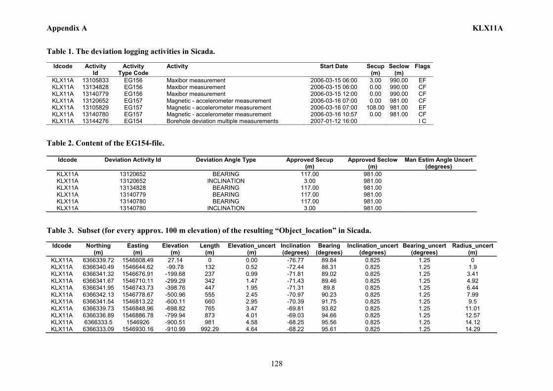
Appendix A KLX11A
128
Table 1. The deviation logging activities in Sicada.
Idcode Activity Id
Activity Type Code
Activity Start Date Secup(m)
Seclow(m)
Flags
KLX11A 13105833 EG156 Maxibor measurement 2006-03-15 06:00 3.00 990.00 EF KLX11A 13134828 EG156 Maxibor measurement 2006-03-15 06:00 0.00 990.00 CF KLX11A 13140779 EG156 Maxibor measurement 2006-03-15 12:00 0.00 990.00 CF KLX11A 13120652 EG157 Magnetic - accelerometer measurement 2006-03-16 07:00 0.00 981.00 CF KLX11A 13105829 EG157 Magnetic - accelerometer measurement 2006-03-16 07:00 108.00 981.00 EF KLX11A 13140780 EG157 Magnetic - accelerometer measurement 2006-03-16 10:57 0.00 981.00 CF KLX11A 13144276 EG154 Borehole deviation multiple measurements 2007-01-12 16:00 I C
Table 2. Content of the EG154-file.
Idcode Deviation Activity Id Deviation Angle Type Approved Secup (m)
Approved Seclow(m)
Man Estim Angle Uncert (degrees)
KLX11A 13120652 BEARING 117.00 981.00 KLX11A 13120652 INCLINATION 3.00 981.00 KLX11A 13134828 BEARING 117.00 981.00 KLX11A 13140779 BEARING 117.00 981.00 KLX11A 13140780 BEARING 117.00 981.00 KLX11A 13140780 INCLINATION 3.00 981.00
Table 3. Subset (for every approx. 100 m elevation) of the resulting “Object_location” in Sicada.
Idcode
Northing
(m) Easting
(m) Elevation
(m) Length
(m) Elevation_uncert
(m) Inclination (degrees)
Bearing (degrees)
Inclination_uncert(degrees)
Bearing_uncert(degrees)
Radius_uncert (m)
KLX11A 6366339.72 1546608.49 27.14 0 0.00 -76.77 89.84 0.825 1.25 0 KLX11A 6366340.49 1546644.62 -99.78 132 0.52 -72.44 88.31 0.825 1.25 1.9 KLX11A 6366341.32 1546676.91 -199.68 237 0.99 -71.81 89.02 0.825 1.25 3.41 KLX11A 6366341.67 1546710.11 -299.29 342 1.47 -71.43 89.46 0.825 1.25 4.92 KLX11A 6366341.95 1546743.73 -398.76 447 1.95 -71.31 89.8 0.825 1.25 6.44 KLX11A 6366342.13 1546778.67 -500.96 555 2.45 -70.97 90.23 0.825 1.25 7.99 KLX11A 6366341.54 1546813.22 -600.11 660 2.95 -70.39 91.75 0.825 1.25 9.5 KLX11A 6366339.73 1546848.96 -698.82 765 3.47 -69.81 93.82 0.825 1.25 11.01 KLX11A 6366336.89 1546886.78 -799.94 873 4.01 -69.03 94.66 0.825 1.25 12.57 KLX11A 6366333.5 1546926 -900.51 981 4.58 -68.25 95.56 0.825 1.25 14.12 KLX11A 6366333.09 1546930.16 -910.99 992.29 4.64 -68.22 95.61 0.825 1.25 14.29
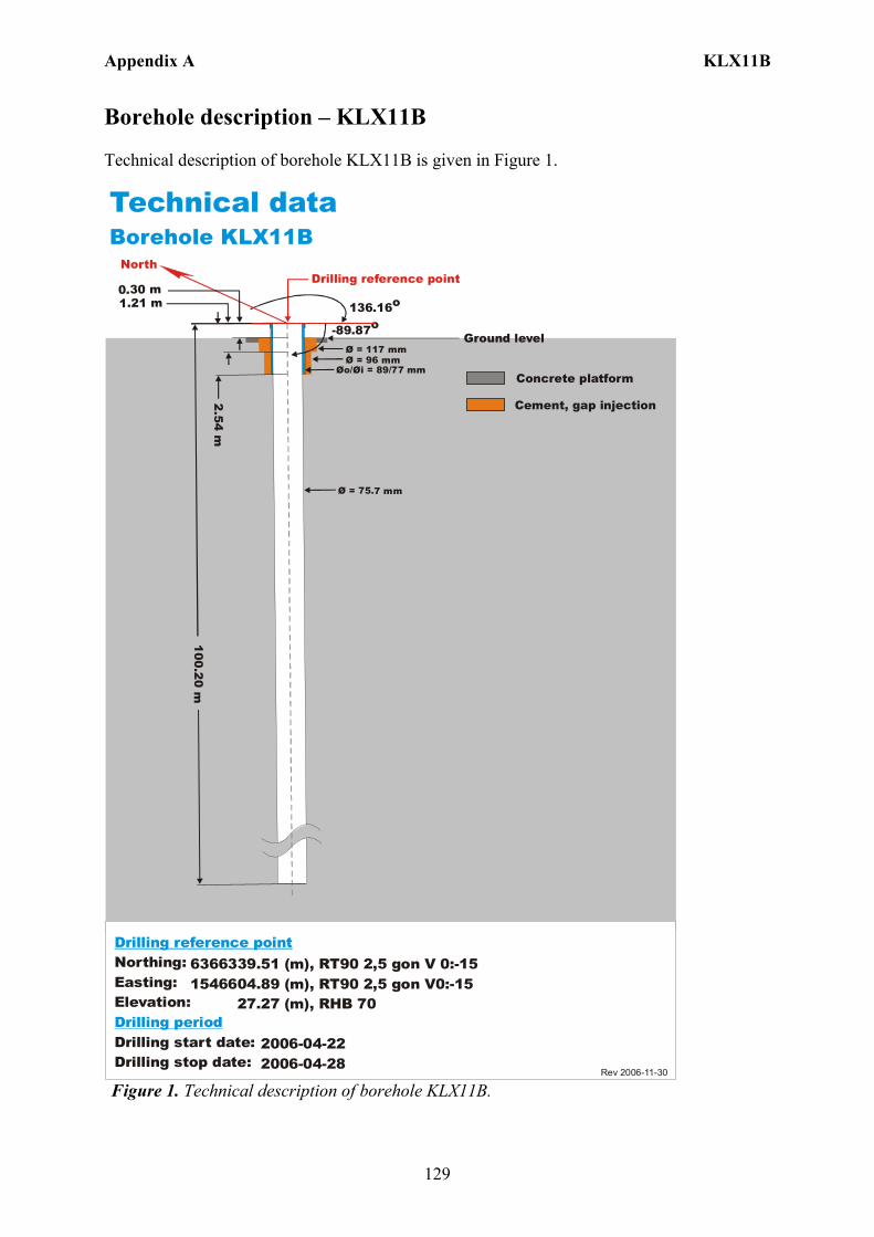
Appendix A KLX11B
129
Borehole description – KLX11B Technical description of borehole KLX11B is given in Figure 1.
6366339.51 (m),1546604.89 (m), 27.27 (m), 2006-04-22 2006-04-28
RT90 2,5 gon V0:-15 RHB 70
RT90 2,5 gon V 0:-15Northing:Easting:Elevation:
Drilling start date:Drilling stop date:
Drilling reference point
Drilling period
Cement, gap injection
Concrete platform
Rev 2006-11-30
Øo/ = 89/77 mmØi
Ø = 117 mm
100.20 m2.54 m
0.30 m
Ø = 75.7 mm
Technical dataBorehole KLX11B
North
136.16o
-89.87o
Drilling reference point
Ground level
1.21 m
Ø = 96 mm
Figure 1. Technical description of borehole KLX11B.

Appendix A KLX11B
130
Deviation measurement in KLX11B In total two deviation measurements were conducted in KLX11B. The deviation logging activities are tabulated in Sicada Activity Log, see Table 1. The two Mac/acc measurements (ID 13140785, 13115947) were executed down and up the borehole, with the Flexit instrument. Corrections of measured data were documented in the File References (Sicada) for the measurements. No geomagnetic disturbances exceeding 0.5 degrees were observed on the date of the Mag/acc measurement, see Figure 2. Borehole deviation multiple measurements For the calculation of Borehole deviation multiple measurements (ID 13144277) the two Mag/acc measurements (ID 13140785, 13115947) were used. Table 2 shows all deviation data for the calculation. A subset of the resulting deviation file for every approximately 100 m elevation (from Object_location) is shown in Table 3. The inclination and bearing uncertainties were calculated automatically, and based on these values the “Radius uncertainty” was calculated for every measuring level. Figure 3 shows the resulting deviation data together with the other, not ERROR- marked, deviation activities listed in Table 1.
Figure 2. The geomagnetic field was observed at the Observatory in Uppsala on 2006-05-09.
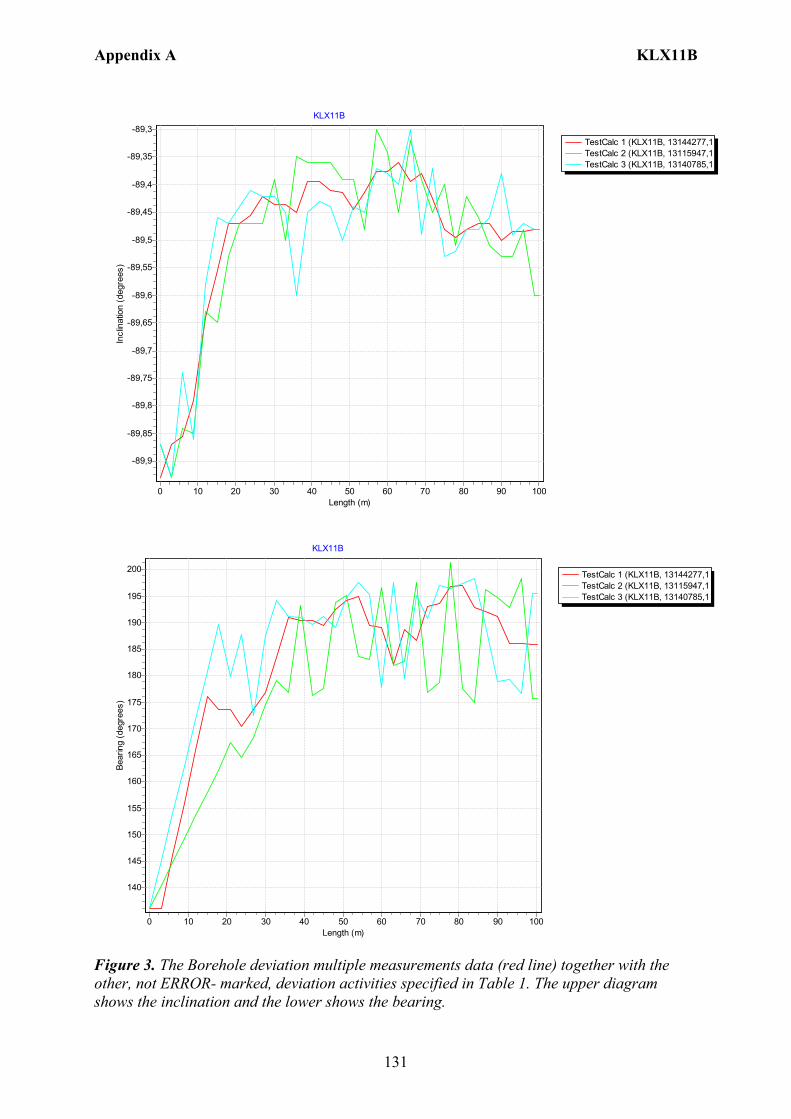
Appendix A KLX11B
131
TestCalc 1 (KLX11B, 13144277,1TestCalc 2 (KLX11B, 13115947,1TestCalc 3 (KLX11B, 13140785,1
KLX11B
Length (m)1009080706050403020100
Incl
inat
ion
(deg
rees
)-89,3
-89,35
-89,4
-89,45
-89,5
-89,55
-89,6
-89,65
-89,7
-89,75
-89,8
-89,85
-89,9
TestCalc 1 (KLX11B, 13144277,1TestCalc 2 (KLX11B, 13115947,1TestCalc 3 (KLX11B, 13140785,1
KLX11B
Length (m)1009080706050403020100
Bear
ing
(deg
rees
)
200
195
190
185
180
175
170
165
160
155
150
145
140
Figure 3. The Borehole deviation multiple measurements data (red line) together with the other, not ERROR- marked, deviation activities specified in Table 1. The upper diagram shows the inclination and the lower shows the bearing.
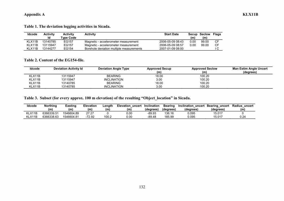
Appendix A KLX11B
132
Table 1. The deviation logging activities in Sicada.
Idcode Activity Id
Activity Type Code
Activity Start Date Secup(m)
Seclow(m)
Flags
KLX11B 13140785 EG157 Magnetic - accelerometer measurement 2006-05-09 08:43 0.00 99.00 CF KLX11B 13115947 EG157 Magnetic - accelerometer measurement 2006-05-09 08:57 0.00 99.00 CF KLX11B 13144277 EG154 Borehole deviation multiple measurements 2007-01-09 08:00 I C
Table 2. Content of the EG154-file.
Idcode Deviation Activity Id Deviation Angle Type Approved Secup (m)
Approved Seclow (m)
Man Estim Angle Uncert (degrees)
KLX11B 13115947 BEARING 18.00 100.20 KLX11B 13115947 INCLINATION 3.00 100.20 KLX11B 13140785 BEARING 18.00 100.20 KLX11B 13140785 INCLINATION 3.00 100.20
Table 3. Subset (for every approx. 100 m elevation) of the resulting “Object_location” in Sicada.
Idcode
Northing (m)
Easting (m)
Elevation (m)
Length (m)
Elevation_uncert(m)
Inclination (degrees)
Bearing (degrees)
Inclination_uncert(degrees)
Bearing_uncert(degrees)
Radius_uncert (m)
KLX11B 6366339.51 1546604.89 27.27 0 0.00 -89.93 136.16 0.095 15.017 0 KLX11B 6366338.63 1546604.81 -72.92 100.2 0.00 -89.48 185.99 0.095 15.017 0.24
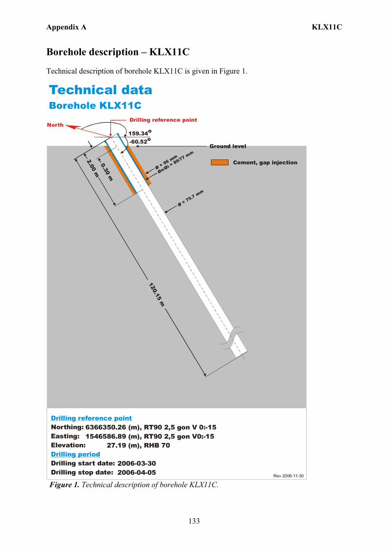
Appendix A KLX11C
133
Borehole description – KLX11C Technical description of borehole KLX11C is given in Figure 1.
6366350.26 (m),1546586.89 (m), 27.19 (m), 2006-03-30 2006-04-05
RT90 2,5 gon V0:-15 RHB 70
RT90 2,5 gon V 0:-15Northing:Easting:Elevation:
Drilling start date:Drilling stop date:
Drilling reference point
Drilling period
Cement, gap injection
Rev 2006-11-30
Technical dataBorehole KLX11C
North159.34o
-60.52o
Drilling reference point
Øo/= 89/77 m
m
Øi Ø = 96 mm
120.15 m
2.00 m0.30 m
Ø = 75.7 mm
Ground level
Figure 1. Technical description of borehole KLX11C.

Appendix A KLX11C
134
Deviation measurement in KLX11C In total two deviation measurements were conducted in KLX11C. The deviation logging activities are tabulated in Sicada Activity Log, see Table 1. The two Mac/acc measurements (ID 13140841, 13115951) were executed down and up the borehole, with the Flexit instrument. Corrections of measured data were documented in the File References (Sicada) for the measurements. No geomagnetic disturbances exceeding 0.5 degrees were observed on the date of the Mag/acc measurement, see Figure 2. Borehole deviation multiple measurements For the calculation of Borehole deviation multiple measurements (ID 13144278) the two Mag/acc measurements (ID 13140841, 13115951) were used. Table 2 shows all deviation data for the calculation. A subset of the resulting deviation file for every approximately 100 m elevation (from Object_location) is shown in Table 3. The inclination and bearing uncertainties were calculated automatically, and based on these values the “Radius uncertainty” was calculated for every measuring level. Figure 3 shows the resulting deviation data together with the other, not ERROR- marked, deviation activities listed in Table 1.
Figure 2. The geomagnetic field was observed at the Observatory in Uppsala on 2006-05-10.
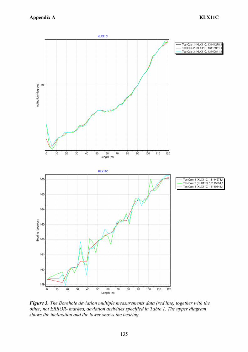
Appendix A KLX11C
135
TestCalc 1 (KLX11C, 13144278,1TestCalc 2 (KLX11C, 13115951,1TestCalc 3 (KLX11C, 13140841,1
KLX11C
Length (m)1201101009080706050403020100
Incl
inat
ion
(deg
rees
)
-60
TestCalc 1 (KLX11C, 13144278,1TestCalc 2 (KLX11C, 13115951,1TestCalc 3 (KLX11C, 13140841,1
KLX11C
Length (m)1201101009080706050403020100
Bear
ing
(deg
rees
)
166
165
164
163
162
161
160
159
Figure 3. The Borehole deviation multiple measurements data (red line) together with the other, not ERROR- marked, deviation activities specified in Table 1. The upper diagram shows the inclination and the lower shows the bearing.

Appendix A KLX11C
136
Table 1. The deviation logging activities in Sicada.
Idcode Activity Id
Activity Type Code
Activity Start Date Secup(m)
Seclow(m)
Flags
KLX11C 13140841 EG157 Magnetic - accelerometer measurement 2006-05-10 20:24 0.00 117.00 CF KLX11C 13115951 EG157 Magnetic - accelerometer measurement 2006-05-10 20:53 0.00 117.00 CF KLX11C 13144278 EG154 Borehole deviation multiple measurements 2007-01-09 08:00 I C
Table 2. Content of the EG154-file.
Idcode Deviation Activity Id Deviation Angle Type Approved Secup (m)
Approved Seclow (m)
Man Estim Angle Uncert (degrees)
KLX11C 13115951 BEARING 18.00 120.15 KLX11C 13115951 INCLINATION 3.00 120.15 KLX11C 13140841 BEARING 18.00 120.15 KLX11C 13140841 INCLINATION 3.00 120.15
Table 3. Subset (for every approx. 100 m elevation) of the resulting “Object_location” in Sicada.
Idcode
Northing (m)
Easting (m)
Elevation (m)
Length (m)
Elevation_uncert(m)
Inclination (degrees)
Bearing (degrees)
Inclination_uncert(degrees)
Bearing_uncert(degrees)
Radius_uncert (m)
KLX11C 6366350.26 1546586.89 27.19 0 0.00 -60.73 159.34 0.03 0.62 0 KLX11C 6366293.47 1546604.85 -77.13 120.15 0.03 -59.41 166.16 0.03 0.62 0.65

Appendix A KLX11D
137
Borehole description – KLX11D Technical description of borehole KLX11D is given in Figure 1.
6366357.37 (m),1546631.42 (m), 25.57 (m), 2006-04-06 2006-04-13
RT90 2,5 gon V0:-15 RHB 70
RT90 2,5 gon V 0:-15Northing:Easting:Elevation:
Drilling start date:Drilling stop date:
Drilling reference point
Drilling period
Cement, gap injection
Rev 2006-11-30
Technical dataBorehole KLX11D
North268.70o
-59.00o
Drilling reference point
Øo/= 89/77 m
m
Øi Ø = 96 mm
120.35 m
2.00 m0.30 m
Ø = 75.7 mm
Ground level
Figure 1. Technical description of borehole KLX11D.

Appendix A KLX11D
138
Deviation measurement in KLX11D In total two deviation measurements were conducted in KLX11D. The deviation logging activities are tabulated in Sicada Activity Log, see Table 1. The two Mac/acc measurements (ID 13141077, 13115961) were executed down and up the borehole, with the Flexit instrument. Corrections of measured data are documented in the File References (Sicada) for the measurements. No geomagnetic disturbances exceeding 0.5 degrees were observed on the date of the Mag/acc measurement, see Figure 2. Borehole deviation multiple measurements For the calculation of Borehole deviation multiple measurements (ID 13144279) the two Mag/acc measurements (ID 13141077, 13115961) were used. Table 2 shows all deviation data for the calculation. A subset of the resulting deviation file for every approximately 100 m elevation (from Object_location) is shown in Table 3. The inclination and bearing uncertainties were calculated automatically, and based on these values the “Radius uncertainty” was calculated for every measuring level. Figure 3 shows the resulting deviation data together with the other, not ERROR- marked, deviation activities listed in Table 1.
Figure 2. The geomagnetic field was observed at the Observatory in Uppsala on 2006-05-09.
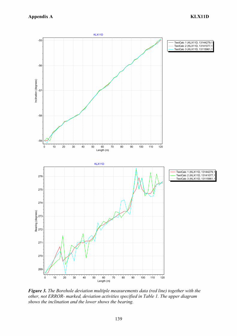
Appendix A KLX11D
139
TestCalc 1 (KLX11D, 13144279,1TestCalc 2 (KLX11D, 13141077,1TestCalc 3 (KLX11D, 13115961,1
KLX11D
Length (m)1201101009080706050403020100
Incl
inat
ion
(deg
rees
)
-55
-56
-57
-58
-59
TestCalc 1 (KLX11D, 13144279,1TestCalc 2 (KLX11D, 13141077,1TestCalc 3 (KLX11D, 13115961,1
KLX11D
Length (m)1201101009080706050403020100
Bear
ing
(deg
rees
)
276
275
274
273
272
271
270
269
Figure 3. The Borehole deviation multiple measurements data (red line) together with the other, not ERROR- marked, deviation activities specified in Table 1. The upper diagram shows the inclination and the lower shows the bearing.
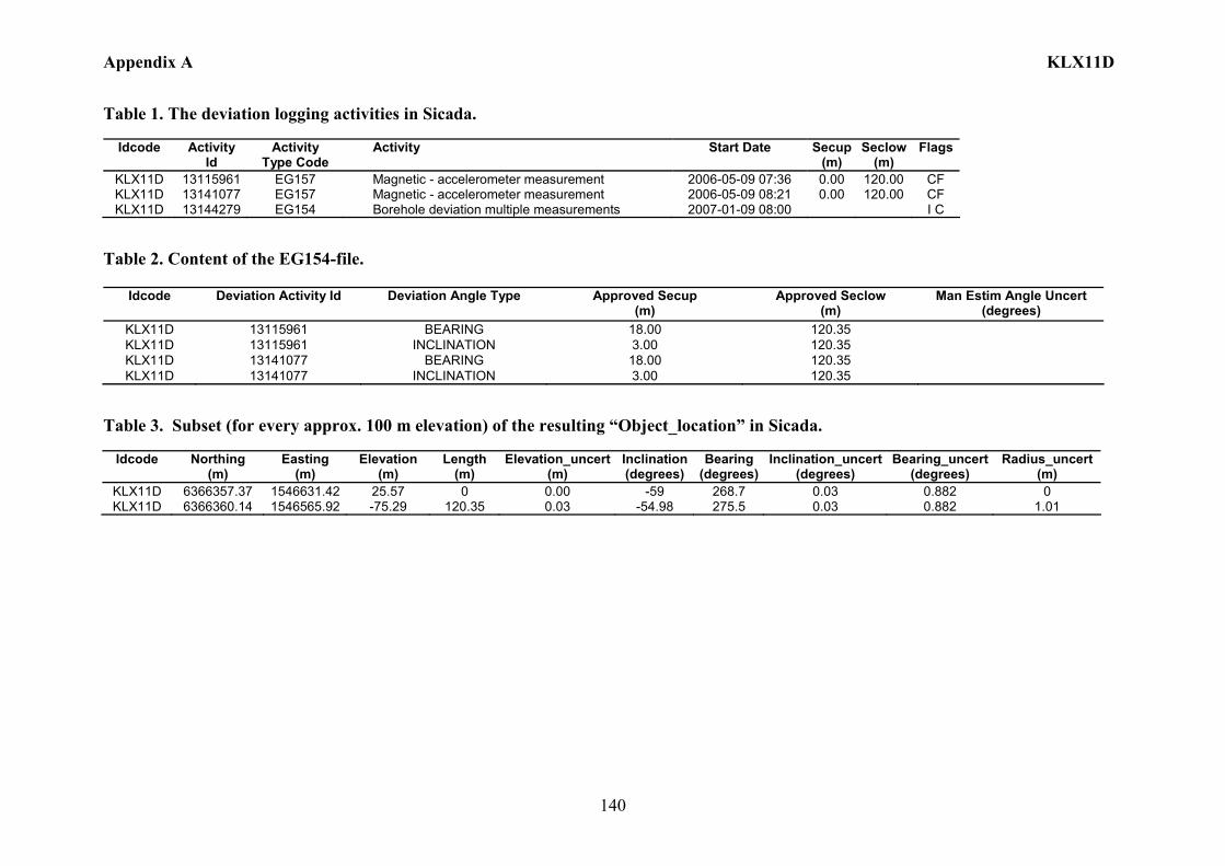
Appendix A KLX11D
140
Table 1. The deviation logging activities in Sicada.
Idcode Activity Id
Activity Type Code
Activity Start Date Secup(m)
Seclow(m)
Flags
KLX11D 13115961 EG157 Magnetic - accelerometer measurement 2006-05-09 07:36 0.00 120.00 CF KLX11D 13141077 EG157 Magnetic - accelerometer measurement 2006-05-09 08:21 0.00 120.00 CF KLX11D 13144279 EG154 Borehole deviation multiple measurements 2007-01-09 08:00 I C
Table 2. Content of the EG154-file.
Idcode Deviation Activity Id Deviation Angle Type Approved Secup (m)
Approved Seclow (m)
Man Estim Angle Uncert (degrees)
KLX11D 13115961 BEARING 18.00 120.35 KLX11D 13115961 INCLINATION 3.00 120.35 KLX11D 13141077 BEARING 18.00 120.35 KLX11D 13141077 INCLINATION 3.00 120.35
Table 3. Subset (for every approx. 100 m elevation) of the resulting “Object_location” in Sicada.
Idcode
Northing (m)
Easting (m)
Elevation (m)
Length (m)
Elevation_uncert(m)
Inclination (degrees)
Bearing (degrees)
Inclination_uncert(degrees)
Bearing_uncert(degrees)
Radius_uncert (m)
KLX11D 6366357.37 1546631.42 25.57 0 0.00 -59 268.7 0.03 0.882 0 KLX11D 6366360.14 1546565.92 -75.29 120.35 0.03 -54.98 275.5 0.03 0.882 1.01

Appendix A KLX11E
141
Borehole description – KLX11E Technical description of borehole KLX11E is given in Figure 1.
6366300.39 (m),1546627.23 (m), 22.65 (m), 2006-04-13 2006-04-21
RT90 2,5 gon V0:-15 RHB 70
RT90 2,5 gon V 0:-15Northing:Easting:Elevation:
Drilling start date:Drilling stop date:
Drilling reference point
Drilling period
Cement, gap injection
Rev 2006-11-30
Technical dataBorehole KLX11E
North336.17o
-60.65o
Drilling reference point
Øo/= 89/77 m
m
Øi Ø = 96 mm
121.30 m
2.00 m0.30 m
Ø = 75.7 mm
Ground level
Figure 1. Technical description of borehole KLX11E.

Appendix A KLX11E
142
Deviation measurement in KLX11E In total two deviation measurements were conducted in KLX11E. The deviation logging activities are tabulated in Sicada Activity Log, see Table 1. The two Mac/acc measurements (ID 13140973, 13115964) were executed down and up the borehole, with the Flexit instrument. Corrections of measured data were documented in the File References (Sicada) for the measurements. No geomagnetic disturbances exceeding 0.5 degrees were observed on the date of the Mag/acc measurement, see Figure 2. Borehole deviation multiple measurements For the calculation of Borehole deviation multiple measurements (ID 13144280) the two Mag/acc measurements (ID 13140973, 13115964) were used. Table 2 shows all deviation data for the calculation. A subset of the resulting deviation file for every approximately 100 m elevation (from Object_location) is shown in Table 3. The inclination and bearing uncertainties were calculated automatically, and based on these values the “Radius uncertainty” was calculated for every measuring level. Figure 3 shows the resulting deviation data together with the other, not ERROR- marked, deviation activities listed in Table 1.
Figure 2. The geomagnetic field was observed at the Observatory in Uppsala on 2006-05-08.
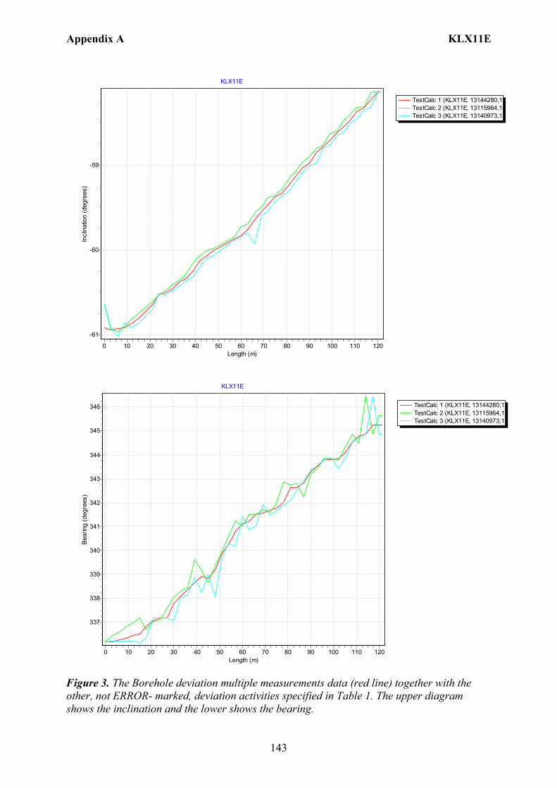
Appendix A KLX11E
143
TestCalc 1 (KLX11E, 13144280,1TestCalc 2 (KLX11E, 13115964,1TestCalc 3 (KLX11E, 13140973,1
KLX11E
Length (m)1201101009080706050403020100
Incl
inat
ion
(deg
rees
)
-59
-60
-61
TestCalc 1 (KLX11E, 13144280,1TestCalc 2 (KLX11E, 13115964,1TestCalc 3 (KLX11E, 13140973,1
KLX11E
Length (m)1201101009080706050403020100
Bear
ing
(deg
rees
)
346
345
344
343
342
341
340
339
338
337
Figure 3. The Borehole deviation multiple measurements data (red line) together with the other, not ERROR- marked, deviation activities specified in Table 1. The upper diagram shows the inclination and the lower shows the bearing.

Appendix A KLX11E
144
Table 1. The deviation logging activities in Sicada.
Idcode Activity Id
Activity Type Code
Activity Start Date Secup(m)
Seclow(m)
Flags
KLX11E 13140973 EG157 Magnetic - accelerometer measurement 2006-05-08 19:35 0.00 120.00 CF KLX11E 13115964 EG157 Magnetic - accelerometer measurement 2006-05-08 19:51 0.00 120.00 CF KLX11E 13144280 EG154 Borehole deviation multiple measurements 2007-01-09 08:00 I C
Table 2. Content of the EG154-file.
Idcode Deviation Activity Id Deviation Angle Type Approved Secup (m)
Approved Seclow (m)
Man Estim Angle Uncert (degrees)
KLX11E 13115964 BEARING 18.00 121.30 KLX11E 13115964 INCLINATION 3.00 121.30 KLX11E 13140973 BEARING 18.00 121.30 KLX11E 13140973 INCLINATION 3.00 121.30
Table 3. Subset (for every approx. 100 m elevation) of the resulting “Object_location” in Sicada.
Idcode
Northing (m)
Easting (m)
Elevation (m)
Length (m)
Elevation_uncert(m)
Inclination (degrees)
Bearing (degrees)
Inclination_uncert(degrees)
Bearing_uncert(degrees)
Radius_uncert (m)
KLX11E 6366300.39 1546627.23 22.65 0 0.00 -60.92 336.17 0.09 0.609 0 KLX11E 6366358.09 1546607 -82.05 121.3 0.10 -58.14 345.25 0.09 0.609 0.65
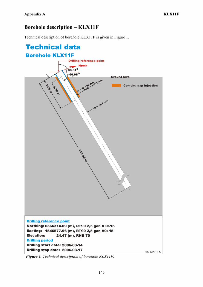
Appendix A KLX11F
145
Borehole description – KLX11F Technical description of borehole KLX11F is given in Figure 1.
6366314.09 (m),1546577.96 (m), 24.47 (m), 2006-03-14 2006-03-17
RT90 2,5 gon V0:-15 RHB 70
RT90 2,5 gon V 0:-15Northing:Easting:Elevation:
Drilling start date:Drilling stop date:
Drilling reference point
Drilling period
Cement, gap injection
Rev 2006-11-30
Technical dataBorehole KLX11F
North88.61o
-60.98o
Drilling reference point
Øo/= 89/77 mm
Øi Ø = 96 mm
120.05 m
2.00 m0.30 m
Ø = 75.7 mm
Ground level
Figure 1. Technical description of borehole KLX11F.

Appendix A KLX11F
146
Deviation measurement in KLX11F In total two deviation measurements were conducted in KLX11F. The deviation logging activities are tabulated in Sicada Activity Log, see Table 1. The two Mac/acc measurements (ID 13140975, 13115943) were executed down and up the borehole length, with the Flexit instrument. Corrections of measured data were documented in the File References (Sicada) for the measurements. No geomagnetic disturbances exceeding 0.5 degrees were observed on the date of the Mag/acc measurement, see Figure 2. Borehole deviation multiple measurements For the calculation of Borehole deviation multiple measurements (ID 13144281) the two Mag/acc measurements (ID 13140975, 13115943) were used. Table 2 shows all deviation data for the calculation. A subset of the resulting deviation file for every approximately 100 m elevation (from Object_location) is shown in Table 3. The inclination and bearing uncertainties were calculated automatically, and based on these values the “Radius uncertainty” was calculated for every measuring level. Figure 3 shows the resulting deviation data together with the other, not ERROR- marked, deviation activities listed in Table 1.
Figure 2. The geomagnetic field was observed at the Observatory in Uppsala on 2006-05-08.
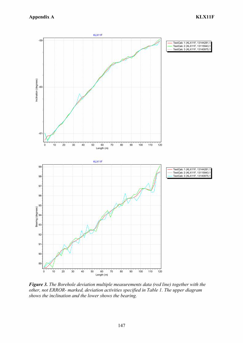
Appendix A KLX11F
147
TestCalc 1 (KLX11F, 13144281,1TestCalc 2 (KLX11F, 13115943,1TestCalc 3 (KLX11F, 13140975,1
KLX11F
Length (m)1201101009080706050403020100
Incl
inat
ion
(deg
rees
)
-59
-60
-61
TestCalc 1 (KLX11F, 13144281,1TestCalc 2 (KLX11F, 13115943,1TestCalc 3 (KLX11F, 13140975,1
KLX11F
Length (m)1201101009080706050403020100
Bear
ing
(deg
rees
)
99
98
97
96
95
94
93
92
91
90
89
Figure 3. The Borehole deviation multiple measurements data (red line) together with the other, not ERROR- marked, deviation activities specified in Table 1. The upper diagram shows the inclination and the lower shows the bearing.
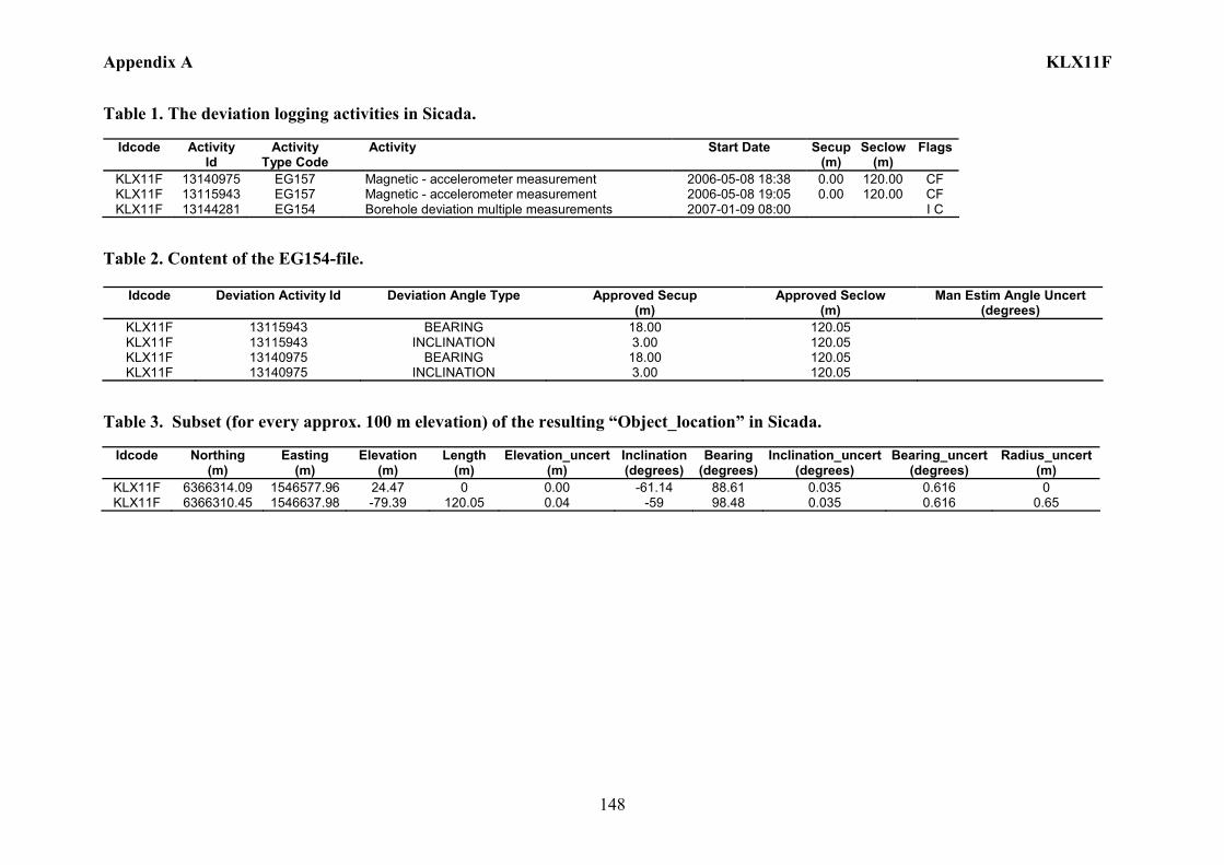
Appendix A KLX11F
148
Table 1. The deviation logging activities in Sicada.
Idcode Activity Id
Activity Type Code
Activity Start Date Secup(m)
Seclow(m)
Flags
KLX11F 13140975 EG157 Magnetic - accelerometer measurement 2006-05-08 18:38 0.00 120.00 CF KLX11F 13115943 EG157 Magnetic - accelerometer measurement 2006-05-08 19:05 0.00 120.00 CF KLX11F 13144281 EG154 Borehole deviation multiple measurements 2007-01-09 08:00 I C
Table 2. Content of the EG154-file.
Idcode Deviation Activity Id Deviation Angle Type Approved Secup (m)
Approved Seclow (m)
Man Estim Angle Uncert (degrees)
KLX11F 13115943 BEARING 18.00 120.05 KLX11F 13115943 INCLINATION 3.00 120.05 KLX11F 13140975 BEARING 18.00 120.05 KLX11F 13140975 INCLINATION 3.00 120.05
Table 3. Subset (for every approx. 100 m elevation) of the resulting “Object_location” in Sicada.
Idcode
Northing (m)
Easting (m)
Elevation (m)
Length (m)
Elevation_uncert(m)
Inclination (degrees)
Bearing (degrees)
Inclination_uncert(degrees)
Bearing_uncert(degrees)
Radius_uncert (m)
KLX11F 6366314.09 1546577.96 24.47 0 0.00 -61.14 88.61 0.035 0.616 0 KLX11F 6366310.45 1546637.98 -79.39 120.05 0.04 -59 98.48 0.035 0.616 0.65

Appendix A KLX12A
149
Borehole description – KLX12A Technical description of borehole KLX12A is given in Figure 1. Technical dataBorehole KLX12A
6365630.78 (m),1548904.44 (m), 17.74 (m), 2005-10-19 2006-03-04
RT90 2,5 gon V 0:-15 RHB 70
RT90 2,5 gon V 0:-15Northing:Easting:Elevation:
Drilling start date:Drilling stop date:
Drilling reference point
Drilling period
North
315.92o
-75.07o
Drilling reference point
Cement, gap injection
Concrete platform
Ver 2007-02-15
Ø = 196.6 mm
Øo/ = 323/310 mm
Øi
Øo/ = 208/200 mm
Øi
Ø = 75.8 mm
A
0.15 m
15.10 m
Ø = 343.0 mm
100.57 m97.36 m
602.29 m
Ø = 160.8 mm
Ø = 86.0 mm100.40 m
102.13 m17.92 m
Ø = 248.0 mm
Ø=195 mm
Øo/ =104/100 mmØi
Ø=84 mmØ=77 mm M80x1.5 mm left hand thread
Øo/ =84/80 mmØi
300
mm
2970
mm
477 0
mm
1800
mm
A
Ground level
Figure 1. Technical description of borehole KLX12A.
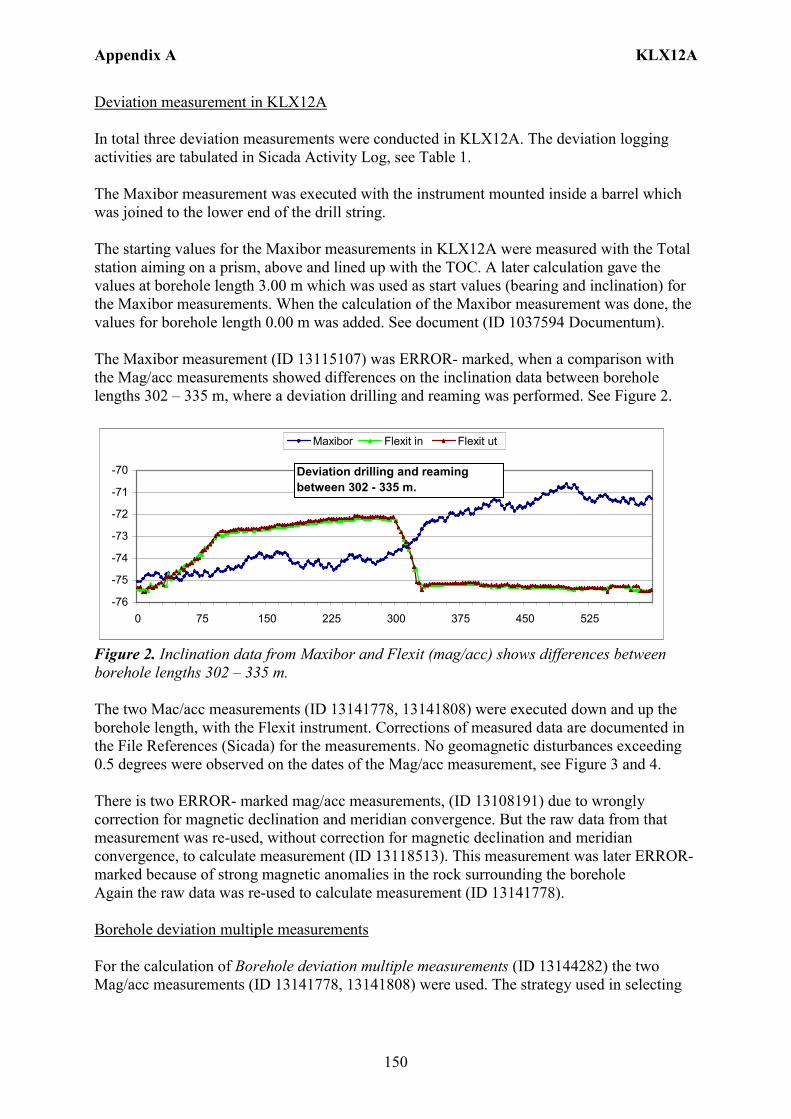
Appendix A KLX12A
150
Deviation measurement in KLX12A In total three deviation measurements were conducted in KLX12A. The deviation logging activities are tabulated in Sicada Activity Log, see Table 1. The Maxibor measurement was executed with the instrument mounted inside a barrel which was joined to the lower end of the drill string. The starting values for the Maxibor measurements in KLX12A were measured with the Total station aiming on a prism, above and lined up with the TOC. A later calculation gave the values at borehole length 3.00 m which was used as start values (bearing and inclination) for the Maxibor measurements. When the calculation of the Maxibor measurement was done, the values for borehole length 0.00 m was added. See document (ID 1037594 Documentum). The Maxibor measurement (ID 13115107) was ERROR- marked, when a comparison with the Mag/acc measurements showed differences on the inclination data between borehole lengths 302 – 335 m, where a deviation drilling and reaming was performed. See Figure 2.
-76
-75
-74
-73
-72
-71
-70
0 75 150 225 300 375 450 525
Maxibor Flexit in Flexit ut
Deviation drilling and reaming between 302 - 335 m.
Figure 2. Inclination data from Maxibor and Flexit (mag/acc) shows differences between borehole lengths 302 – 335 m. The two Mac/acc measurements (ID 13141778, 13141808) were executed down and up the borehole length, with the Flexit instrument. Corrections of measured data are documented in the File References (Sicada) for the measurements. No geomagnetic disturbances exceeding 0.5 degrees were observed on the dates of the Mag/acc measurement, see Figure 3 and 4. There is two ERROR- marked mag/acc measurements, (ID 13108191) due to wrongly correction for magnetic declination and meridian convergence. But the raw data from that measurement was re-used, without correction for magnetic declination and meridian convergence, to calculate measurement (ID 13118513). This measurement was later ERROR- marked because of strong magnetic anomalies in the rock surrounding the borehole Again the raw data was re-used to calculate measurement (ID 13141778). Borehole deviation multiple measurements For the calculation of Borehole deviation multiple measurements (ID 13144282) the two Mag/acc measurements (ID 13141778, 13141808) were used. The strategy used in selecting
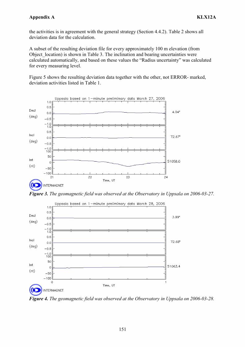
Appendix A KLX12A
151
the activities is in agreement with the general strategy (Section 4.4.2). Table 2 shows all deviation data for the calculation. A subset of the resulting deviation file for every approximately 100 m elevation (from Object_location) is shown in Table 3. The inclination and bearing uncertainties were calculated automatically, and based on these values the “Radius uncertainty” was calculated for every measuring level. Figure 5 shows the resulting deviation data together with the other, not ERROR- marked, deviation activities listed in Table 1.
Figure 3. The geomagnetic field was observed at the Observatory in Uppsala on 2006-03-27.
Figure 4. The geomagnetic field was observed at the Observatory in Uppsala on 2006-03-28.
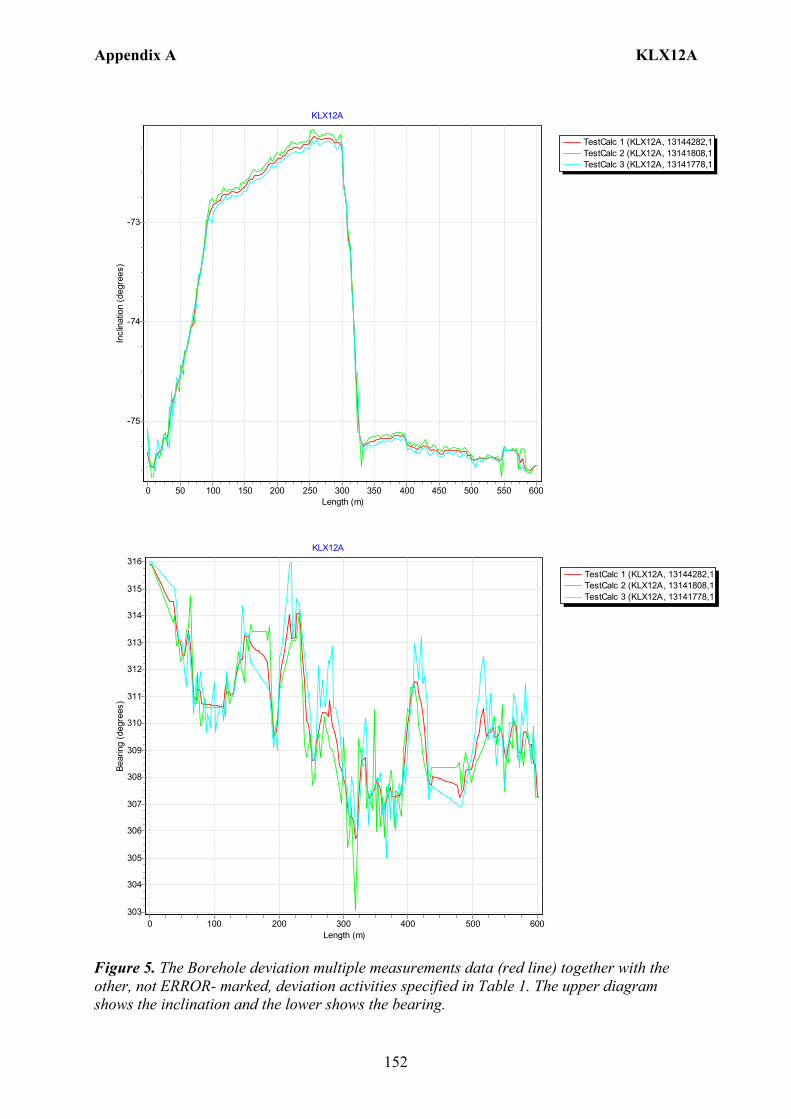
Appendix A KLX12A
152
TestCalc 1 (KLX12A, 13144282,1TestCalc 2 (KLX12A, 13141808,1TestCalc 3 (KLX12A, 13141778,1
KLX12A
Length (m)600550500450400350300250200150100500
Incl
inat
ion
(deg
rees
)
-73
-74
-75
TestCalc 1 (KLX12A, 13144282,1TestCalc 2 (KLX12A, 13141808,1TestCalc 3 (KLX12A, 13141778,1
KLX12A
Length (m)6005004003002001000
Bear
ing
(deg
rees
)
316
315
314
313
312
311
310
309
308
307
306
305
304
303
Figure 5. The Borehole deviation multiple measurements data (red line) together with the other, not ERROR- marked, deviation activities specified in Table 1. The upper diagram shows the inclination and the lower shows the bearing.
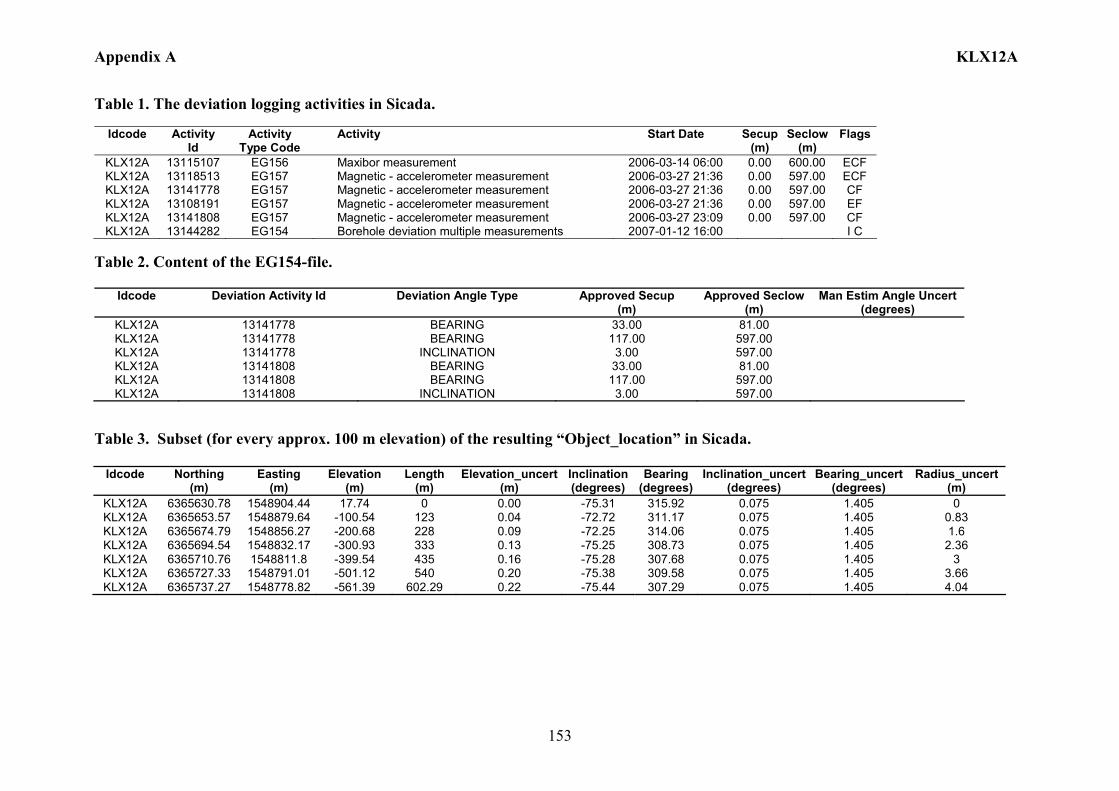
Appendix A KLX12A
153
Table 1. The deviation logging activities in Sicada.
Idcode Activity Id
Activity Type Code
Activity Start Date Secup(m)
Seclow(m)
Flags
KLX12A 13115107 EG156 Maxibor measurement 2006-03-14 06:00 0.00 600.00 ECF KLX12A 13118513 EG157 Magnetic - accelerometer measurement 2006-03-27 21:36 0.00 597.00 ECF KLX12A 13141778 EG157 Magnetic - accelerometer measurement 2006-03-27 21:36 0.00 597.00 CF KLX12A 13108191 EG157 Magnetic - accelerometer measurement 2006-03-27 21:36 0.00 597.00 EF KLX12A 13141808 EG157 Magnetic - accelerometer measurement 2006-03-27 23:09 0.00 597.00 CF KLX12A 13144282 EG154 Borehole deviation multiple measurements 2007-01-12 16:00 I C
Table 2. Content of the EG154-file.
Idcode Deviation Activity Id Deviation Angle Type Approved Secup (m)
Approved Seclow(m)
Man Estim Angle Uncert (degrees)
KLX12A 13141778 BEARING 33.00 81.00 KLX12A 13141778 BEARING 117.00 597.00 KLX12A 13141778 INCLINATION 3.00 597.00 KLX12A 13141808 BEARING 33.00 81.00 KLX12A 13141808 BEARING 117.00 597.00 KLX12A 13141808 INCLINATION 3.00 597.00
Table 3. Subset (for every approx. 100 m elevation) of the resulting “Object_location” in Sicada.
Idcode
Northing (m)
Easting (m)
Elevation (m)
Length (m)
Elevation_uncert(m)
Inclination (degrees)
Bearing (degrees)
Inclination_uncert(degrees)
Bearing_uncert(degrees)
Radius_uncert (m)
KLX12A 6365630.78 1548904.44 17.74 0 0.00 -75.31 315.92 0.075 1.405 0 KLX12A 6365653.57 1548879.64 -100.54 123 0.04 -72.72 311.17 0.075 1.405 0.83 KLX12A 6365674.79 1548856.27 -200.68 228 0.09 -72.25 314.06 0.075 1.405 1.6 KLX12A 6365694.54 1548832.17 -300.93 333 0.13 -75.25 308.73 0.075 1.405 2.36 KLX12A 6365710.76 1548811.8 -399.54 435 0.16 -75.28 307.68 0.075 1.405 3 KLX12A 6365727.33 1548791.01 -501.12 540 0.20 -75.38 309.58 0.075 1.405 3.66 KLX12A 6365737.27 1548778.82 -561.39 602.29 0.22 -75.44 307.29 0.075 1.405 4.04

Appendix A KLX13A
154
Borehole description – KLX13A Technical description of borehole KLX13A is given in Figure 1.
6367547.144 (m),1546787.363 (m), 24.153 (m), 2006-05-19 2006-08-16
RT90 2,5 gon V 0:-15 RHB 70
RT90 2,5 gon V 0:-15Northing:Easting:Elevation:
Drilling start date:Drilling stop date:
Drilling reference point
Drilling period
Cement, gap injection
Concrete platform
Ver 2007-04-12
Technical dataBorehole KLX13A
North 224.482o
-82.253o
Drilling reference point
Ø = 196.8 mm
Ø = 197.3 mm
Øo/ = 323/310 mm
Øi
Øo/ = 208/200 mm
Øi
Ø = 75.8 mm
A
0.15 m
6.15 m
Ø = 341.0 mm
99.86 m96.11 m
595.85 m
Ø = 160.4 mm
Ø = 86.0 mm
99.60 m99.08 m
101.21 m11.75 m
Ø = 251.5 mm
Ø=195 mm
Øo/ =104/100 mmØi
Ø=84 mmØ=77 mm M80x1.5 mm left hand thread
Øo/ =84/80 mmØi
300
mm
2 970
mm
510
0 m
m2
130
mm
A
Ground level
Figure 1. Technical description of borehole KLX13A.
Appendix A KLX13A
155
Deviation measurement in KLX13A In total four deviation measurements were conducted in KLX13A. The deviation logging activities are tabulated in Sicada Activity Log, see Table 1. The two Maxibor measurements were executed with the instrument mounted inside a barrel which was joined to the lower end of the drill string. The starting values for the Maxibor measurements in KLX13A were measured with the Total station aiming on a prism, above and lined up with the TOC. A later calculation gave the values at borehole length 3.00 m which was used as start values (bearing and inclination) for the Maxibor measurements. When the calculation of the Maxibor measurement was done, the values for borehole length 0.00 m was added. See document (ID 1037594 Documentum). The two Maxibor measurements (ID 13120921, 13142365) were executed down and up the borehole length. The two Mac/acc measurements (ID 13142373, 13142385) were executed down and up the borehole, with the Flexit instrument. Corrections of measured data were documented in the File References (Sicada) for the measurements. No geomagnetic disturbances exceeding 0.5 degrees were observed on the dates of the Mag/acc measurement, see Figure 2 and 3. There is two ERROR- marked mag/acc measurements, (ID 13121776) due to editing. But the raw data from that measurement was re-used to calculate measurement (ID 13121310). This measurement was later ERROR- marked because of wrong coordinates. Again the raw data was re-used to calculate measurement (ID 13142373). Borehole deviation multiple measurements For the calculation of Borehole deviation multiple measurements (ID 13144283) the two Maxibor measurements (ID 13120921, 13142365) and the two Mag/acc measurements (ID 13142373,13142385) were used. The strategy used in selecting the activities was in agreement with the general strategy (Section 4.4.2). Table 2 shows all deviation data for the calculation. A subset of the resulting deviation file for every approximately 100 m elevation (from Object_location) is shown in Table 3. The inclination and bearing uncertainties were calculated automatically, and based on these values the “Radius uncertainty” was calculated for every measuring level. Figure 4 shows the resulting deviation data together with the other, not ERROR- marked, deviation activities listed in Table 1.
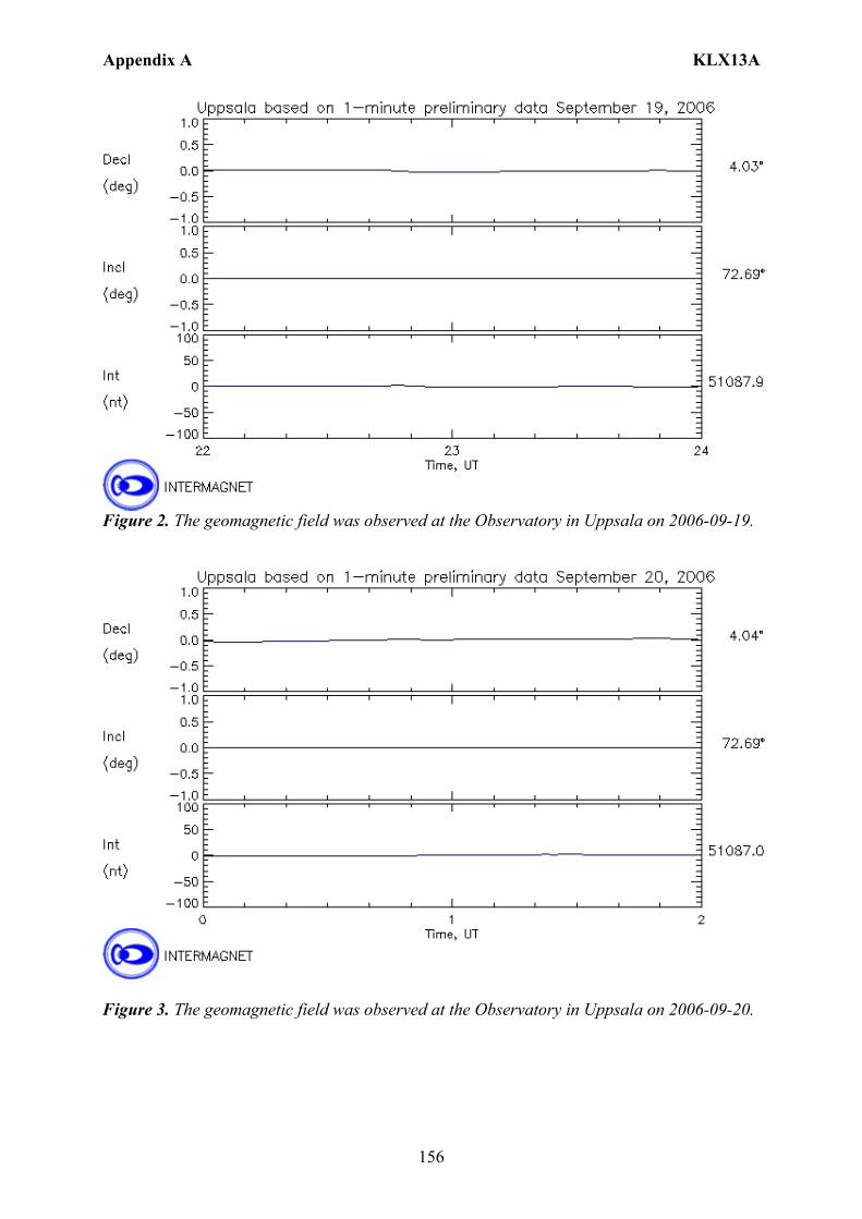
Appendix A KLX13A
156
Figure 2. The geomagnetic field was observed at the Observatory in Uppsala on 2006-09-19.
Figure 3. The geomagnetic field was observed at the Observatory in Uppsala on 2006-09-20.
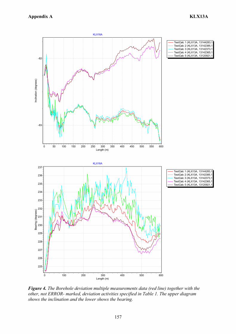
Appendix A KLX13A
157
TestCalc 1 (KLX13A, 13144283,1TestCalc 2 (KLX13A, 13142385,1TestCalc 3 (KLX13A, 13142373,1TestCalc 4 (KLX13A, 13142365,1TestCalc 5 (KLX13A, 13120921,1
KLX16A
Length (m)600550500450400350300250200150100500
Incl
inat
ion
(deg
rees
)
-82
-83
TestCalc 1 (KLX13A, 13144283,1TestCalc 2 (KLX13A, 13142385,1TestCalc 3 (KLX13A, 13142373,1TestCalc 4 (KLX13A, 13142365,1TestCalc 5 (KLX13A, 13120921,1
KLX16A
Length (m)6005004003002001000
Bear
ing
(deg
rees
)
237
236
235
234
233
232
231
230
229
228
227
226
225
Figure 4. The Borehole deviation multiple measurements data (red line) together with the other, not ERROR- marked, deviation activities specified in Table 1. The upper diagram shows the inclination and the lower shows the bearing.
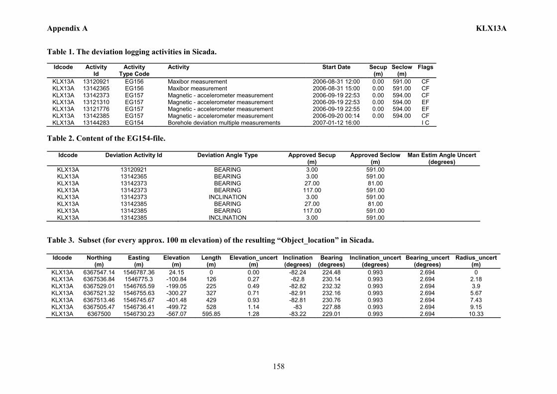
Appendix A KLX13A
158
Table 1. The deviation logging activities in Sicada.
Idcode Activity Id
Activity Type Code
Activity Start Date Secup(m)
Seclow(m)
Flags
KLX13A 13120921 EG156 Maxibor measurement 2006-08-31 12:00 0.00 591.00 CF KLX13A 13142365 EG156 Maxibor measurement 2006-08-31 15:00 0.00 591.00 CF KLX13A 13142373 EG157 Magnetic - accelerometer measurement 2006-09-19 22:53 0.00 594.00 CF KLX13A 13121310 EG157 Magnetic - accelerometer measurement 2006-09-19 22:53 0.00 594.00 EF KLX13A 13121776 EG157 Magnetic - accelerometer measurement 2006-09-19 22:55 0.00 594.00 EF KLX13A 13142385 EG157 Magnetic - accelerometer measurement 2006-09-20 00:14 0.00 594.00 CF KLX13A 13144283 EG154 Borehole deviation multiple measurements 2007-01-12 16:00 I C
Table 2. Content of the EG154-file.
Idcode Deviation Activity Id Deviation Angle Type Approved Secup (m)
Approved Seclow(m)
Man Estim Angle Uncert (degrees)
KLX13A 13120921 BEARING 3.00 591.00 KLX13A 13142365 BEARING 3.00 591.00 KLX13A 13142373 BEARING 27.00 81.00 KLX13A 13142373 BEARING 117.00 591.00 KLX13A 13142373 INCLINATION 3.00 591.00 KLX13A 13142385 BEARING 27.00 81.00 KLX13A 13142385 BEARING 117.00 591.00 KLX13A 13142385 INCLINATION 3.00 591.00
Table 3. Subset (for every approx. 100 m elevation) of the resulting “Object_location” in Sicada.
Idcode
Northing (m)
Easting (m)
Elevation (m)
Length (m)
Elevation_uncert(m)
Inclination (degrees)
Bearing (degrees)
Inclination_uncert(degrees)
Bearing_uncert(degrees)
Radius_uncert (m)
KLX13A 6367547.14 1546787.36 24.15 0 0.00 -82.24 224.48 0.993 2.694 0 KLX13A 6367536.84 1546775.3 -100.84 126 0.27 -82.8 230.14 0.993 2.694 2.18 KLX13A 6367529.01 1546765.59 -199.05 225 0.49 -82.82 232.32 0.993 2.694 3.9 KLX13A 6367521.32 1546755.63 -300.27 327 0.71 -82.91 232.16 0.993 2.694 5.67 KLX13A 6367513.46 1546745.67 -401.48 429 0.93 -82.81 230.76 0.993 2.694 7.43 KLX13A 6367505.47 1546736.41 -499.72 528 1.14 -83 227.88 0.993 2.694 9.15 KLX13A 6367500 1546730.23 -567.07 595.85 1.28 -83.22 229.01 0.993 2.694 10.33

Appendix A KLX14A
159
Borehole description – KLX14A Technical description of borehole KLX14A is given in Figure 1.
6365959.69 (m),1547146.87 (m), 16.35 (m), 2006-08-19 2006-09-04
RT90 2,5 gon V 0:-15 RHB 70
RT90 2,5 gon V 0:-15Northing:Easting:Elevation:
Drilling start date:Drilling stop date:
Drilling reference point
Drilling period
Cement, gap injection
Ver 2007-04-12
Technical dataBorehole KLX14A
North
-49.96o
Drilling reference point
Ground level
111.95o
Øo/= 90/77 mm
Øi Ø = 96 mm 6.45 m0.30 m
Ø = 75.7 mm
Ø = 116 mm
3.20 m
Figure 1. Technical description of borehole KLX14A.

Appendix A KLX14A
160
Deviation measurement in KLX14A In total two deviation measurements were conducted in KLX14A. The deviation logging activities are tabulated in Sicada Activity Log, see Table 1. The two Mac/acc measurements (ID 13140187, 13140188) were executed down and up the borehole, with the Flexit instrument. Corrections of measured data are documented in the File References (Sicada) for the measurements. No geomagnetic disturbances exceeding 0.5 degrees were observed on the date of the Mag/acc measurement, see Figure 2. There is one ERROR- marked mag/acc measurement, (ID 13121779) due to editing. But the raw data from that measurement was re-used to calculate measurement (ID 13140187). Borehole deviation multiple measurements For the calculation of Borehole deviation multiple measurements (ID 13144284) the two Mag/acc measurements (ID 13140187, 13140188) were used. Table 2 shows all deviation data for the calculation. A subset of the resulting deviation file for every approximately 100 m elevation (from Object_location) is shown in Table 3. The inclination and bearing uncertainties were calculated automatically, and based on these values the “Radius uncertainty” was calculated for every measuring level. Figure 3 shows the resulting deviation data together with the other, not ERROR- marked, deviation activities listed in Table 1.

Appendix A KLX14A
161
Figure 2. The geomagnetic field was observed at the Observatory in Uppsala on 2006-09-20.
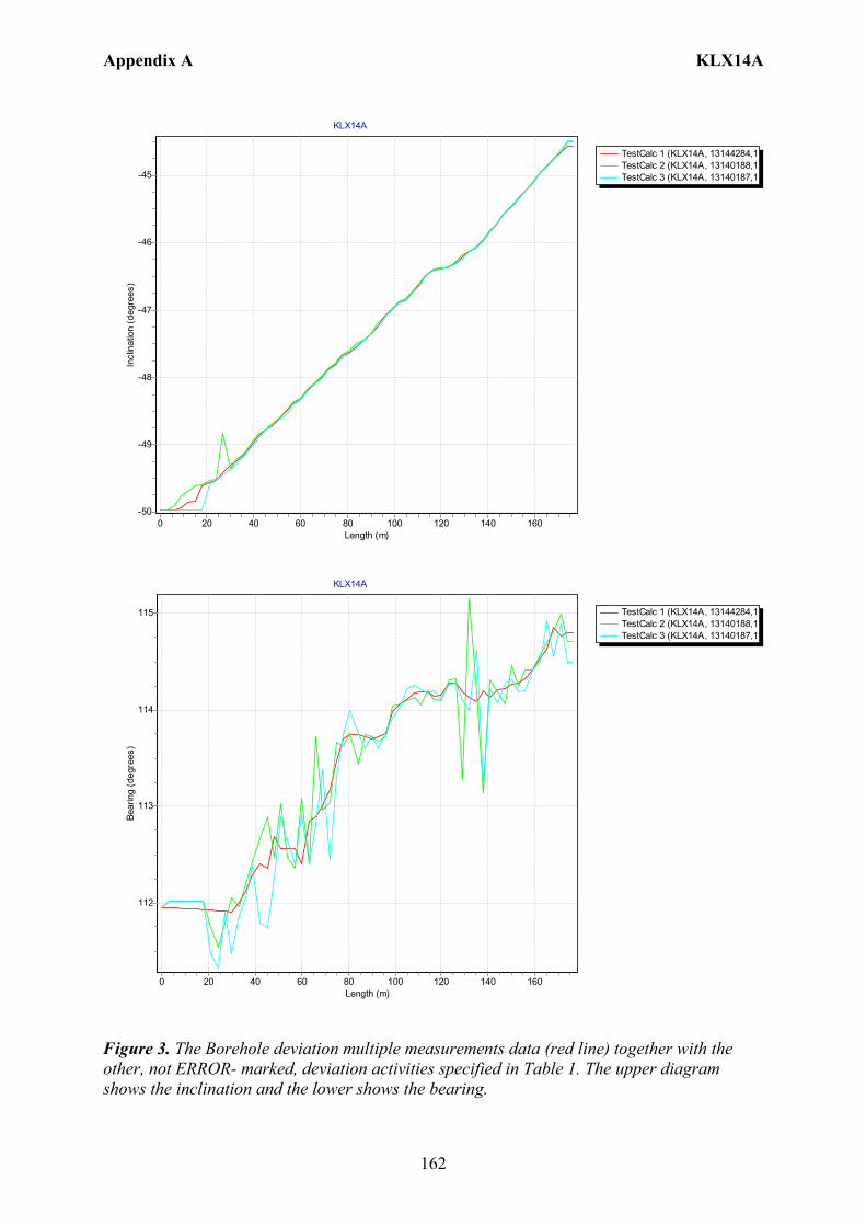
Appendix A KLX14A
162
TestCalc 1 (KLX14A, 13144284,1TestCalc 2 (KLX14A, 13140188,1TestCalc 3 (KLX14A, 13140187,1
KLX14A
Length (m)160140120100806040200
Incl
inat
ion
(deg
rees
)
-45
-46
-47
-48
-49
-50
TestCalc 1 (KLX14A, 13144284,1TestCalc 2 (KLX14A, 13140188,1TestCalc 3 (KLX14A, 13140187,1
KLX14A
Length (m)160140120100806040200
Bear
ing
(deg
rees
)
115
114
113
112
Figure 3. The Borehole deviation multiple measurements data (red line) together with the other, not ERROR- marked, deviation activities specified in Table 1. The upper diagram shows the inclination and the lower shows the bearing.
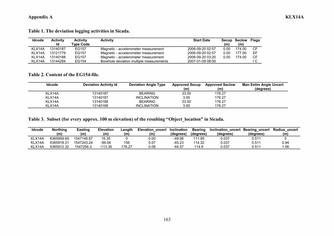
Appendix A KLX14A
163
Table 1. The deviation logging activities in Sicada.
Idcode Activity Id
Activity Type Code
Activity Start Date Secup(m)
Seclow(m)
Flags
KLX14A 13140187 EG157 Magnetic - accelerometer measurement 2006-09-20 02:57 0.00 174.00 CF KLX14A 13121779 EG157 Magnetic - accelerometer measurement 2006-09-20 02:57 0.00 177.00 EF KLX14A 13140188 EG157 Magnetic - accelerometer measurement 2006-09-20 03:20 0.00 174.00 CF KLX14A 13144284 EG154 Borehole deviation multiple measurements 2007-01-09 08:00 I C
Table 2. Content of the EG154-file.
Idcode Deviation Activity Id Deviation Angle Type Approved Secup (m)
Approved Seclow (m)
Man Estim Angle Uncert (degrees)
KLX14A 13140187 BEARING 33.00 176.27 KLX14A 13140187 INCLINATION 3.00 176.27 KLX14A 13140188 BEARING 33.00 176.27 KLX14A 13140188 INCLINATION 3.00 176.27
Table 3. Subset (for every approx. 100 m elevation) of the resulting “Object_location” in Sicada.
Idcode
Northing (m)
Easting (m)
Elevation (m)
Length (m)
Elevation_uncert(m)
Inclination (degrees)
Bearing (degrees)
Inclination_uncert(degrees)
Bearing_uncert(degrees)
Radius_uncert (m)
KLX14A 6365959.69 1547146.87 16.35 0 0.00 -49.96 111.95 0.037 0.511 0 KLX14A 6365918.31 1547243.24 -99.06 156 0.07 -45.23 114.32 0.037 0.511 0.94 KLX14A 6365912.32 1547256.3 -113.36 176.27 0.08 -44.57 114.8 0.037 0.511 1.06
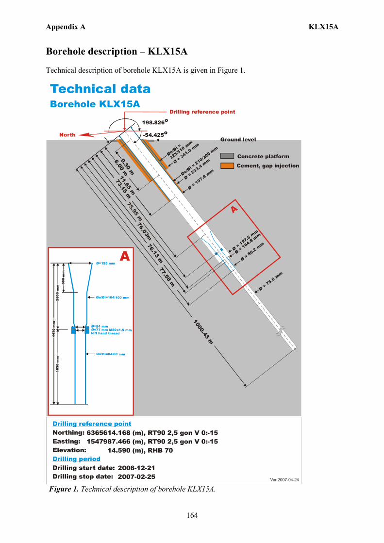
Appendix A KLX15A
164
Borehole description – KLX15A Technical description of borehole KLX15A is given in Figure 1.
6365614.168 (m),1547987.466 (m), 14.590 (m), 2006-12-21 2007-02-25
RT90 2,5 gon V 0:-15 RHB 70
RT90 2,5 gon V 0:-15Northing:Easting:Elevation:
Drilling start date:Drilling stop date:
Drilling reference point
Drilling period
Ver 2007-04-24
Technical dataBorehole KLX15A
Drilling reference point
North
198.826o
-54.425o
Ø = 197.8 mm
Ø = 1957. m
m
Øo/=
323/310 mm
Øi
Øo/= 210/200 m
m
Øi
Ø = 75.8 mm
A
0.30 m
6.00 m
Ø = 341.0 mm
76.13 m
73.15 m
1000.43 m
Ø = 164.8 mm
Ø = 86.2 mm
76.03m
77.58 m
11.65 m
Ø = 233.4 mm
Cement, gap injection
Concrete platform
Ground level
Ø=195 mm
Øo/ =104/100 mmØi
Ø=84 mmØ=77 mm M80x1.5 mm left hand thread
Øo/ =84/80 mmØi
300
mm
2800
mm
443 0
mm
1630
mm
A
Figure 1. Technical description of borehole KLX15A.
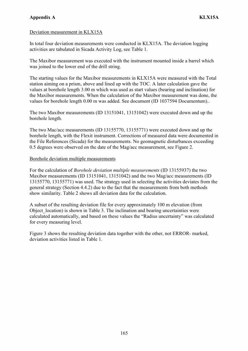
Appendix A KLX15A
165
Deviation measurement in KLX15A In total four deviation measurements were conducted in KLX15A. The deviation logging activities are tabulated in Sicada Activity Log, see Table 1. The Maxibor measurement was executed with the instrument mounted inside a barrel which was joined to the lower end of the drill string. The starting values for the Maxibor measurements in KLX15A were measured with the Total station aiming on a prism, above and lined up with the TOC. A later calculation gave the values at borehole length 3.00 m which was used as start values (bearing and inclination) for the Maxibor measurements. When the calculation of the Maxibor measurement was done, the values for borehole length 0.00 m was added. See document (ID 1037594 Documentum).. The two Maxibor measurements (ID 13151041, 13151042) were executed down and up the borehole length. The two Mac/acc measurements (ID 13155770, 13155771) were executed down and up the borehole length, with the Flexit instrument. Corrections of measured data were documented in the File References (Sicada) for the measurements. No geomagnetic disturbances exceeding 0.5 degrees were observed on the date of the Mag/acc measurement, see Figure 2. Borehole deviation multiple measurements For the calculation of Borehole deviation multiple measurements (ID 13155937) the two Maxibor measurements (ID 13151041, 13151042) and the two Mag/acc measurements (ID 13155770, 13155771) was used. The strategy used in selecting the activities deviates from the general strategy (Section 4.4.2) due to the fact that the measurements from both methods show similarity. Table 2 shows all deviation data for the calculation. A subset of the resulting deviation file for every approximately 100 m elevation (from Object_location) is shown in Table 3. The inclination and bearing uncertainties were calculated automatically, and based on these values the “Radius uncertainty” was calculated for every measuring level. Figure 3 shows the resulting deviation data together with the other, not ERROR- marked, deviation activities listed in Table 1.

Appendix A KLX15A
166
Figure 2. The geomagnetic field was observed at the Observatory in Uppsala on 2007-04-01.
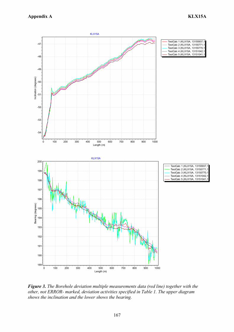
Appendix A KLX15A
167
TestCalc 1 (KLX15A, 13155937,1TestCalc 2 (KLX15A, 13155771,1TestCalc 3 (KLX15A, 13155770,1TestCalc 4 (KLX15A, 13151042,1TestCalc 5 (KLX15A, 13151041,1
KLX15A
Length (m)10009008007006005004003002001000
Incl
inat
ion
(deg
rees
)
-47
-48
-49
-50
-51
-52
-53
-54
TestCalc 1 (KLX15A, 13155937,1TestCalc 2 (KLX15A, 13155771,1TestCalc 3 (KLX15A, 13155770,1TestCalc 4 (KLX15A, 13151042,1TestCalc 5 (KLX15A, 13151041,1
KLX15A
Length (m)10009008007006005004003002001000
Bear
ing
(deg
rees
)
200
199
198
197
196
195
194
193
192
191
190
189
Figure 3. The Borehole deviation multiple measurements data (red line) together with the other, not ERROR- marked, deviation activities specified in Table 1. The upper diagram shows the inclination and the lower shows the bearing.
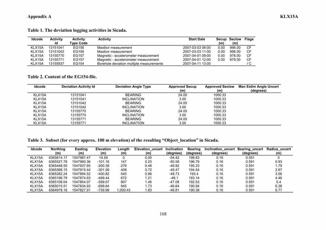
Appendix A KLX15A
168
Table 1. The deviation logging activities in Sicada.
Idcode Activity Id
Activity Type Code
Activity Start Date Secup(m)
Seclow(m)
Flags
KLX15A 13151041 EG156 Maxibor measurement 2007-03-03 06:00 0.00 996.00 CF KLX15A 13151042 EG156 Maxibor measurement 2007-03-03 11:00 0.00 996.00 CF KLX15A 13155770 EG157 Magnetic - accelerometer measurement 2007-04-01 09:00 0.00 978.00 CF KLX15A 13155771 EG157 Magnetic - accelerometer measurement 2007-04-01 12:00 0.00 978.00 CF KLX15A 13155937 EG154 Borehole deviation multiple measurements 2007-04-11 13:00 I C
Table 2. Content of the EG154-file.
Idcode Deviation Activity Id Deviation Angle Type Approved Secup (m)
Approved Seclow(m)
Man Estim Angle Uncert (degrees)
KLX15A 13151041 BEARING 24.00 1000.33 KLX15A 13151041 INCLINATION 3.00 1000.33 KLX15A 13151042 BEARING 24.00 1000.33 KLX15A 13151042 INCLINATION 3.00 1000.33 KLX15A 13155770 BEARING 24.00 1000.33 KLX15A 13155770 INCLINATION 3.00 1000.33 KLX15A 13155771 BEARING 24.00 1000.33 KLX15A 13155771 INCLINATION 3.00 1000.33
Table 3. Subset (for every approx. 100 m elevation) of the resulting “Object_location” in Sicada.
Idcode
Northing
(m) Easting
(m) Elevation
(m) Length
(m) Elevation_uncert
(m) Inclination (degrees)
Bearing (degrees)
Inclination_uncert(degrees)
Bearing_uncert(degrees)
Radius_uncert (m)
KLX15A 6365614.17 1547987.47 14.59 0 0.00 -54.42 198.83 0.16 0.591 0 KLX15A 6365527.78 1547960.36 -101.16 147 0.25 -50.58 196.79 0.16 0.591 0.93 KLX15A 6365448.55 1547937.65 -200.39 276 0.48 -49.92 195.33 0.16 0.591 1.79 KLX15A 6365366.15 1547915.44 -301.09 408 0.72 -49.47 194.54 0.16 0.591 2.67 KLX15A 6365282.24 1547894.52 -400.82 540 0.96 -48.73 193.4 0.16 0.591 3.56 KLX15A 6365196.79 1547874.63 -499.44 672 1.21 -48.1 193.14 0.16 0.591 4.46 KLX15A 6365108.04 1547854.07 -599.07 807 1.46 -47.08 192.53 0.16 0.591 5.4 KLX15A 6365015.51 1547834.93 -699.64 945 1.73 -46.64 190.94 0.16 0.591 6.38 KLX15A 6364978.16 1547827.91 -739.99 1,000.43 1.83 -46.81 190.38 0.16 0.591 6.77
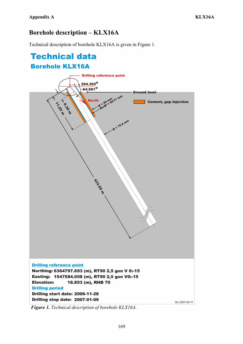
Appendix A KLX16A
169
Borehole description – KLX16A Technical description of borehole KLX16A is given in Figure 1.
6364797.693 (m),1547584.058 (m), 18.853 (m), 2006-11-28 2007-01-09
RT90 2,5 gon V0:-15 RHB 70
RT90 2,5 gon V 0:-15Northing:Easting:Elevation:
Drilling start date:Drilling stop date:
Drilling reference point
Drilling period
Cement, gap injection
Ver 2007-04-11
Technical dataBorehole KLX16A
North
294.365o
-64.981o
Drilling reference point
Øo/= 90/77 mm
Øi Ø = 96 mm
433.55 m
11.25 m0.30 m
Ø = 75.8 mm
Ground level
Figure 1. Technical description of borehole KLX16A.
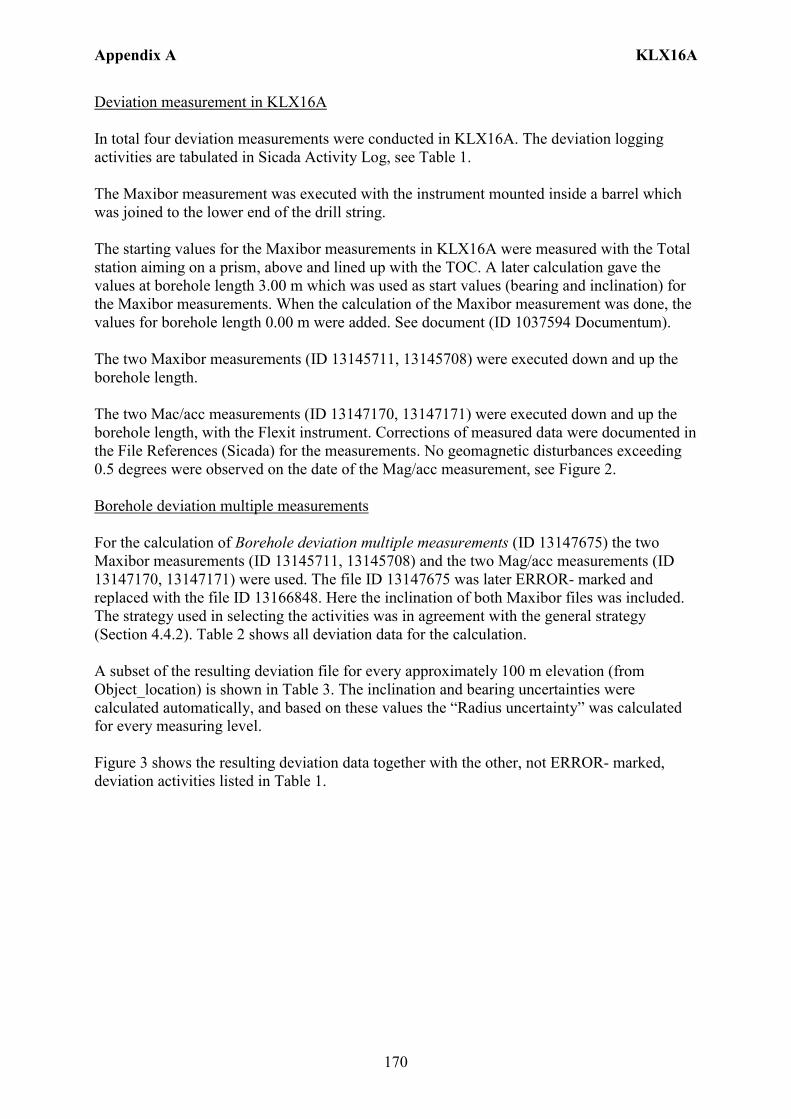
Appendix A KLX16A
170
Deviation measurement in KLX16A In total four deviation measurements were conducted in KLX16A. The deviation logging activities are tabulated in Sicada Activity Log, see Table 1. The Maxibor measurement was executed with the instrument mounted inside a barrel which was joined to the lower end of the drill string. The starting values for the Maxibor measurements in KLX16A were measured with the Total station aiming on a prism, above and lined up with the TOC. A later calculation gave the values at borehole length 3.00 m which was used as start values (bearing and inclination) for the Maxibor measurements. When the calculation of the Maxibor measurement was done, the values for borehole length 0.00 m were added. See document (ID 1037594 Documentum). The two Maxibor measurements (ID 13145711, 13145708) were executed down and up the borehole length. The two Mac/acc measurements (ID 13147170, 13147171) were executed down and up the borehole length, with the Flexit instrument. Corrections of measured data were documented in the File References (Sicada) for the measurements. No geomagnetic disturbances exceeding 0.5 degrees were observed on the date of the Mag/acc measurement, see Figure 2. Borehole deviation multiple measurements For the calculation of Borehole deviation multiple measurements (ID 13147675) the two Maxibor measurements (ID 13145711, 13145708) and the two Mag/acc measurements (ID 13147170, 13147171) were used. The file ID 13147675 was later ERROR- marked and replaced with the file ID 13166848. Here the inclination of both Maxibor files was included. The strategy used in selecting the activities was in agreement with the general strategy (Section 4.4.2). Table 2 shows all deviation data for the calculation. A subset of the resulting deviation file for every approximately 100 m elevation (from Object_location) is shown in Table 3. The inclination and bearing uncertainties were calculated automatically, and based on these values the “Radius uncertainty” was calculated for every measuring level. Figure 3 shows the resulting deviation data together with the other, not ERROR- marked, deviation activities listed in Table 1.

Appendix A KLX16A
171
Figure 2. The geomagnetic field was observed at the Observatory in Uppsala on 2007-01-31.
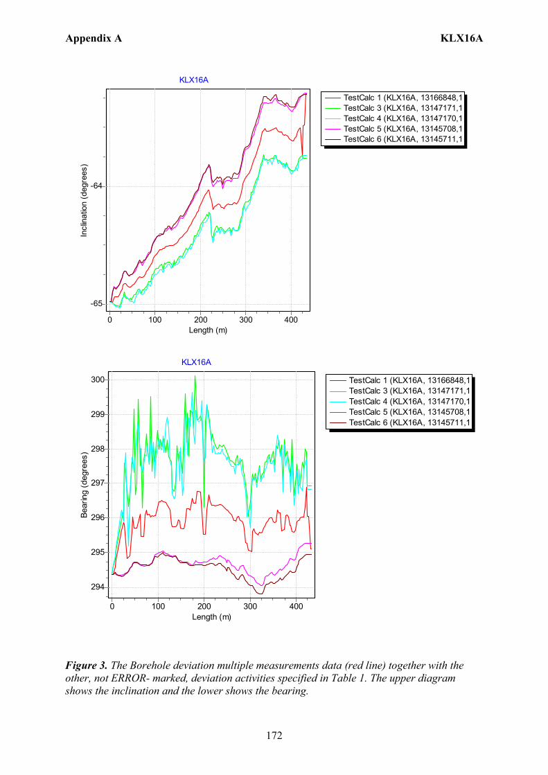
Appendix A KLX16A
172
TestCalc 1 (KLX16A, 13166848,1TestCalc 3 (KLX16A, 13147171,1TestCalc 4 (KLX16A, 13147170,1TestCalc 5 (KLX16A, 13145708,1TestCalc 6 (KLX16A, 13145711,1
KLX16A
Length (m)4003002001000
Incl
inat
ion
(deg
rees
)
-64
-65
TestCalc 1 (KLX16A, 13166848,1TestCalc 3 (KLX16A, 13147171,1TestCalc 4 (KLX16A, 13147170,1TestCalc 5 (KLX16A, 13145708,1TestCalc 6 (KLX16A, 13145711,1
KLX16A
Length (m)4003002001000
Bear
ing
(deg
rees
)
300
299
298
297
296
295
294
Figure 3. The Borehole deviation multiple measurements data (red line) together with the other, not ERROR- marked, deviation activities specified in Table 1. The upper diagram shows the inclination and the lower shows the bearing.
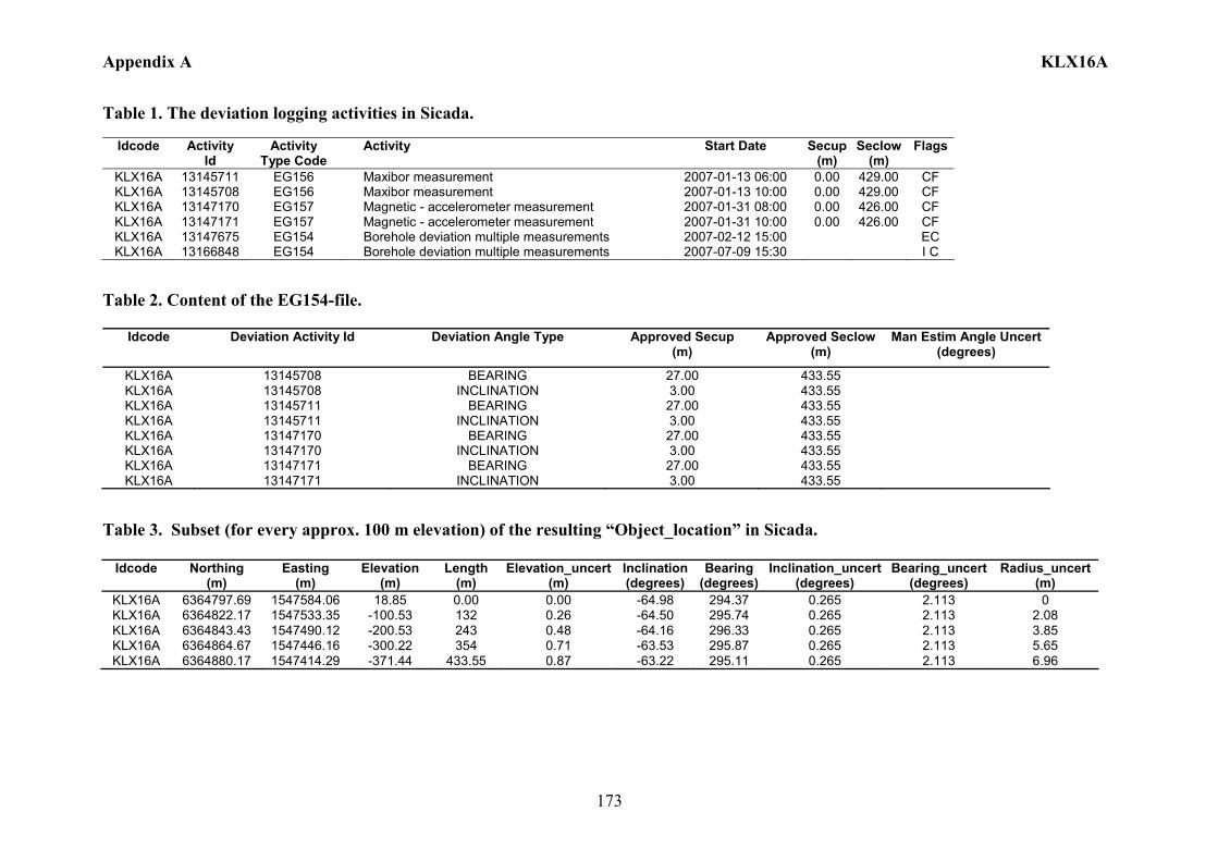
Appendix A KLX16A
173
Table 1. The deviation logging activities in Sicada.
Idcode Activity Id
Activity Type Code
Activity Start Date Secup(m)
Seclow(m)
Flags
KLX16A 13145711 EG156 Maxibor measurement 2007-01-13 06:00 0.00 429.00 CF KLX16A 13145708 EG156 Maxibor measurement 2007-01-13 10:00 0.00 429.00 CF KLX16A 13147170 EG157 Magnetic - accelerometer measurement 2007-01-31 08:00 0.00 426.00 CF KLX16A 13147171 EG157 Magnetic - accelerometer measurement 2007-01-31 10:00 0.00 426.00 CF KLX16A 13147675 EG154 Borehole deviation multiple measurements 2007-02-12 15:00 EC KLX16A 13166848 EG154 Borehole deviation multiple measurements 2007-07-09 15:30 I C
Table 2. Content of the EG154-file.
Idcode Deviation Activity Id Deviation Angle Type Approved Secup (m)
Approved Seclow(m)
Man Estim Angle Uncert (degrees)
KLX16A 13145708 BEARING 27.00 433.55 KLX16A 13145708 INCLINATION 3.00 433.55 KLX16A 13145711 BEARING 27.00 433.55 KLX16A 13145711 INCLINATION 3.00 433.55 KLX16A 13147170 BEARING 27.00 433.55 KLX16A 13147170 INCLINATION 3.00 433.55 KLX16A 13147171 BEARING 27.00 433.55 KLX16A 13147171 INCLINATION 3.00 433.55
Table 3. Subset (for every approx. 100 m elevation) of the resulting “Object_location” in Sicada.
Idcode
Northing (m)
Easting (m)
Elevation (m)
Length (m)
Elevation_uncert(m)
Inclination (degrees)
Bearing (degrees)
Inclination_uncert(degrees)
Bearing_uncert(degrees)
Radius_uncert (m)
KLX16A 6364797.69 1547584.06 18.85 0.00 0.00 -64.98 294.37 0.265 2.113 0 KLX16A 6364822.17 1547533.35 -100.53 132 0.26 -64.50 295.74 0.265 2.113 2.08 KLX16A 6364843.43 1547490.12 -200.53 243 0.48 -64.16 296.33 0.265 2.113 3.85 KLX16A 6364864.67 1547446.16 -300.22 354 0.71 -63.53 295.87 0.265 2.113 5.65 KLX16A 6364880.17 1547414.29 -371.44 433.55 0.87 -63.22 295.11 0.265 2.113 6.96
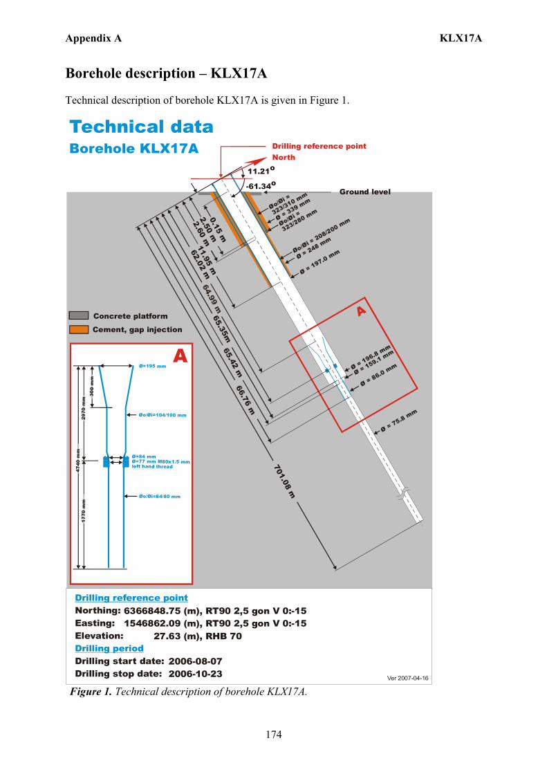
Appendix A KLX17A
174
Borehole description – KLX17A Technical description of borehole KLX17A is given in Figure 1.
6366848.75 (m),1546862.09 (m), 27.63 (m), 2006-08-07 2006-10-23
RT90 2,5 gon V 0:-15 RHB 70
RT90 2,5 gon V 0:-15Northing:Easting:Elevation:
Drilling start date:Drilling stop date:
Drilling reference point
Drilling period
Ver 2007-04-16
Technical dataBorehole KLX17A Drilling reference point
Cement, gap injection
Concrete platform
Ground level
Ø=195 mm
Øo/ =104/100 mmØi
Ø=84 mmØ=77 mm M80x1.5 mm left hand thread
Øo/ =84/80 mmØi
300
mm
2970
mm
4740
mm
1770
mm
A
North
11.21o
-61.34o
Ø = 197.0 mm
Ø = 196.8 mm
Øo/=
323/310 mmØi
Øo/=
323/280 mmØi
Øo/= 208/200 mm
Øi
Ø = 75.8 mm
A0.15 m
2.60 m2.50 m
Ø = 339 mm
65.42 m
62.02 m
701.08 m
Ø = 159.1 mm
Ø = 86.0 mm
65.35m66.76 m
11.95 m
Ø = 248 mm
Figure 1. Technical description of borehole KLX17A.
Appendix A KLX17A
175
Deviation measurement in KLX17A In total five deviation measurements were conducted in KLX17A. The deviation logging activities are tabulated in Sicada Activity Log, see Table 1. The Maxibor measurement was executed with the instrument mounted inside a barrel which was joined to the lower end of the drill string. The starting values for the Maxibor measurements in KLX17A were measured with the Total station aiming on a prism, above and lined up with the TOC. A later calculation gave the values at borehole length 3.00 m which was used as start values (bearing and inclination) for the Maxibor measurements. When the calculation of the Maxibor measurement was done, the values for borehole length 0.00 m were added. See document (ID 1037594 Documentum). Maxibor measurement (ID 13131113) was conducted to check the bearing of the borehole between borehole lengths 0 – 237 m due to indications of deviation. The two Maxibor measurements (ID 13134857, 13134858) were executed down and up the borehole. The two Mac/acc measurements (ID 13138552, 13138553) were executed down and up the borehole, with the Flexit instrument. These measurements were ERROR- marked due to magnetic anomalies in the surrounding rock of the borehole. Borehole deviation multiple measurements For the calculation of Borehole deviation multiple measurements (ID 13144285) the two Maxibor measurements (ID13134857,13134858) were used. The strategy used in selecting the activities was in agreement with the general strategy (Section 4.4.2). Table 2 shows all deviation data for the calculation. A subset of the resulting deviation file for every approximately 100 m elevation (from Object_location) is shown in Table 3. Because the two deviation activities in EG154 (Table 2) were very similar the “Radius uncertainty” would be unrealistically low, and it was decided to set the inclination and bearing uncertainties manually to 1.8º and 4.9º respectively (see section 4.4.2), and based on these values the “Radius uncertainty” was calculated for every measuring level. Figure 2 shows the resulting deviation data together with the other, not ERROR- marked, deviation activities listed in Table 1.

Appendix A KLX17A
176
TestCalc 1 (KLX17A, 13144285,1TestCalc 2 (KLX17A, 13134857,1TestCalc 3 (KLX17A, 13134858,1
KLX17A
Length (m)7006005004003002001000
Incl
inat
ion
(deg
rees
)-56
-57
-58
-59
-60
-61
TestCalc 1 (KLX17A, 13144285,1TestCalc 2 (KLX17A, 13134857,1TestCalc 3 (KLX17A, 13134858,1
KLX17A
Length (m)7006005004003002001000
Bear
ing
(deg
rees
)
18
17
16
15
14
13
12
11
Figure 2. The Borehole deviation multiple measurements data (red line) together with the other, not ERROR- marked, deviation activities specified in Table 1. The upper diagram shows the inclination and the lower shows the bearing. The borehole was percussion drilled down to 65.42 m. The borehole was also reamed down to 172.98 m due to small rock pieces falling into the borehole.
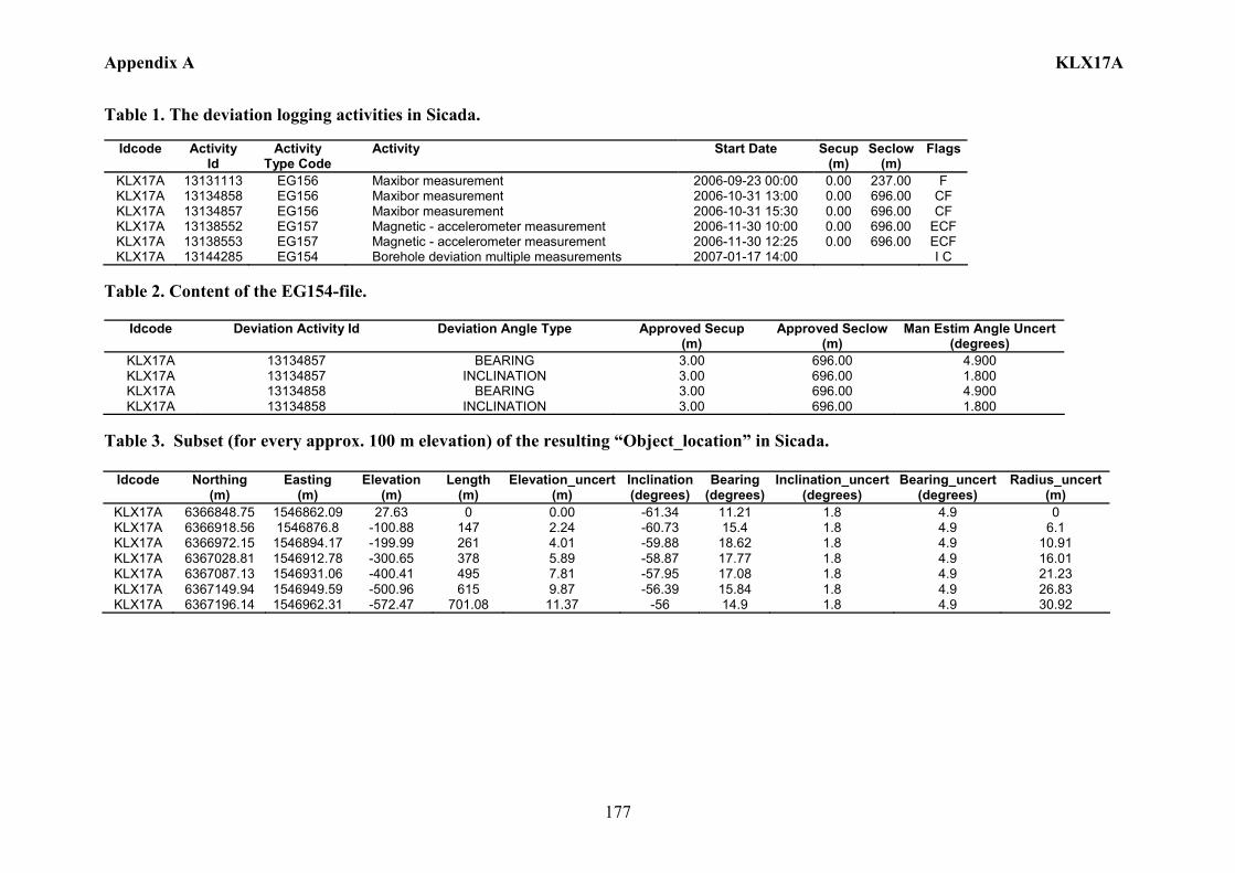
Appendix A KLX17A
177
Table 1. The deviation logging activities in Sicada.
Idcode Activity Id
Activity Type Code
Activity Start Date Secup(m)
Seclow(m)
Flags
KLX17A 13131113 EG156 Maxibor measurement 2006-09-23 00:00 0.00 237.00 F KLX17A 13134858 EG156 Maxibor measurement 2006-10-31 13:00 0.00 696.00 CF KLX17A 13134857 EG156 Maxibor measurement 2006-10-31 15:30 0.00 696.00 CF KLX17A 13138552 EG157 Magnetic - accelerometer measurement 2006-11-30 10:00 0.00 696.00 ECF KLX17A 13138553 EG157 Magnetic - accelerometer measurement 2006-11-30 12:25 0.00 696.00 ECF KLX17A 13144285 EG154 Borehole deviation multiple measurements 2007-01-17 14:00 I C
Table 2. Content of the EG154-file.
Idcode Deviation Activity Id Deviation Angle Type Approved Secup (m)
Approved Seclow(m)
Man Estim Angle Uncert (degrees)
KLX17A 13134857 BEARING 3.00 696.00 4.900 KLX17A 13134857 INCLINATION 3.00 696.00 1.800 KLX17A 13134858 BEARING 3.00 696.00 4.900 KLX17A 13134858 INCLINATION 3.00 696.00 1.800
Table 3. Subset (for every approx. 100 m elevation) of the resulting “Object_location” in Sicada.
Idcode
Northing (m)
Easting (m)
Elevation (m)
Length (m)
Elevation_uncert(m)
Inclination (degrees)
Bearing (degrees)
Inclination_uncert(degrees)
Bearing_uncert(degrees)
Radius_uncert (m)
KLX17A 6366848.75 1546862.09 27.63 0 0.00 -61.34 11.21 1.8 4.9 0 KLX17A 6366918.56 1546876.8 -100.88 147 2.24 -60.73 15.4 1.8 4.9 6.1 KLX17A 6366972.15 1546894.17 -199.99 261 4.01 -59.88 18.62 1.8 4.9 10.91 KLX17A 6367028.81 1546912.78 -300.65 378 5.89 -58.87 17.77 1.8 4.9 16.01 KLX17A 6367087.13 1546931.06 -400.41 495 7.81 -57.95 17.08 1.8 4.9 21.23 KLX17A 6367149.94 1546949.59 -500.96 615 9.87 -56.39 15.84 1.8 4.9 26.83 KLX17A 6367196.14 1546962.31 -572.47 701.08 11.37 -56 14.9 1.8 4.9 30.92
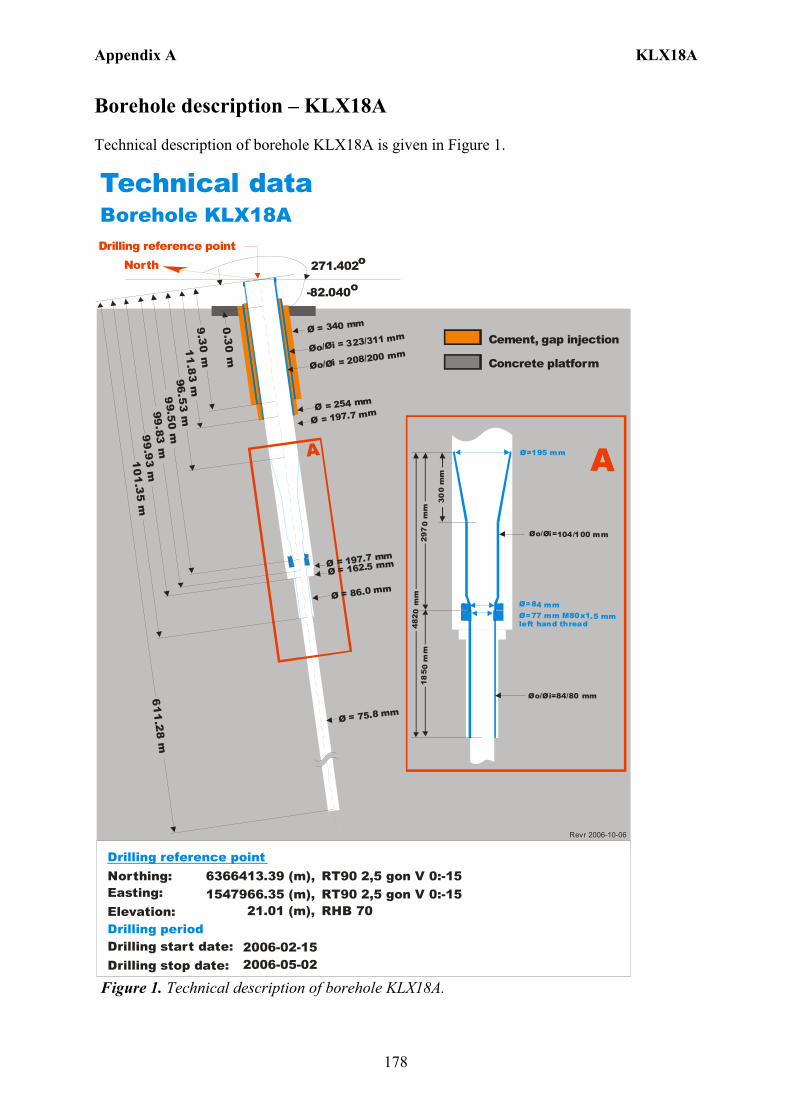
Appendix A KLX18A
178
Borehole description – KLX18A Technical description of borehole KLX18A is given in Figure 1. Technical dataBorehole KLX18A
6366413.39 (m),1547966.35 (m), 21.01 (m),
2006-02-15 2006-05-02
RT90 2,5 gon V 0:-15 RHB 70
RT90 2,5 gon V 0:-15Northing:Easting:Elevation:
Drilling start date:Drilling stop date:
Drilling reference point
Drilling period
North 271.402o
-82.040o
Drilling reference point
Cement, gap injection
Concrete platform
9.30 m
Ø = 197.7 mm
Øo/ = 323/311 mmØi
Øo/ = 208/200 mmØi
Ø = 75.8 mm
A
0.30 m
Ø = 86.0 mm1
1.83
m
99 .83 m96. 5
3 m
99
. 93
m6
11. 28
m
Ø = 340 mm
Ø = 254 mm
10
1. 35 m
99.5
0 m
Ø=195 mm
Øo/ =104/100 mmØi
Ø=84 mmØ=77 mm M80x1.5 mm left hand thread
Øo/ =84/80 mmØi
300
mm
297
0 m
m48
2 0 m
m18
5 0 m
m
A
Ø = 197.7 mmØ = 162.5 mm
Revr 2006-10-06
Figure 1. Technical description of borehole KLX18A.
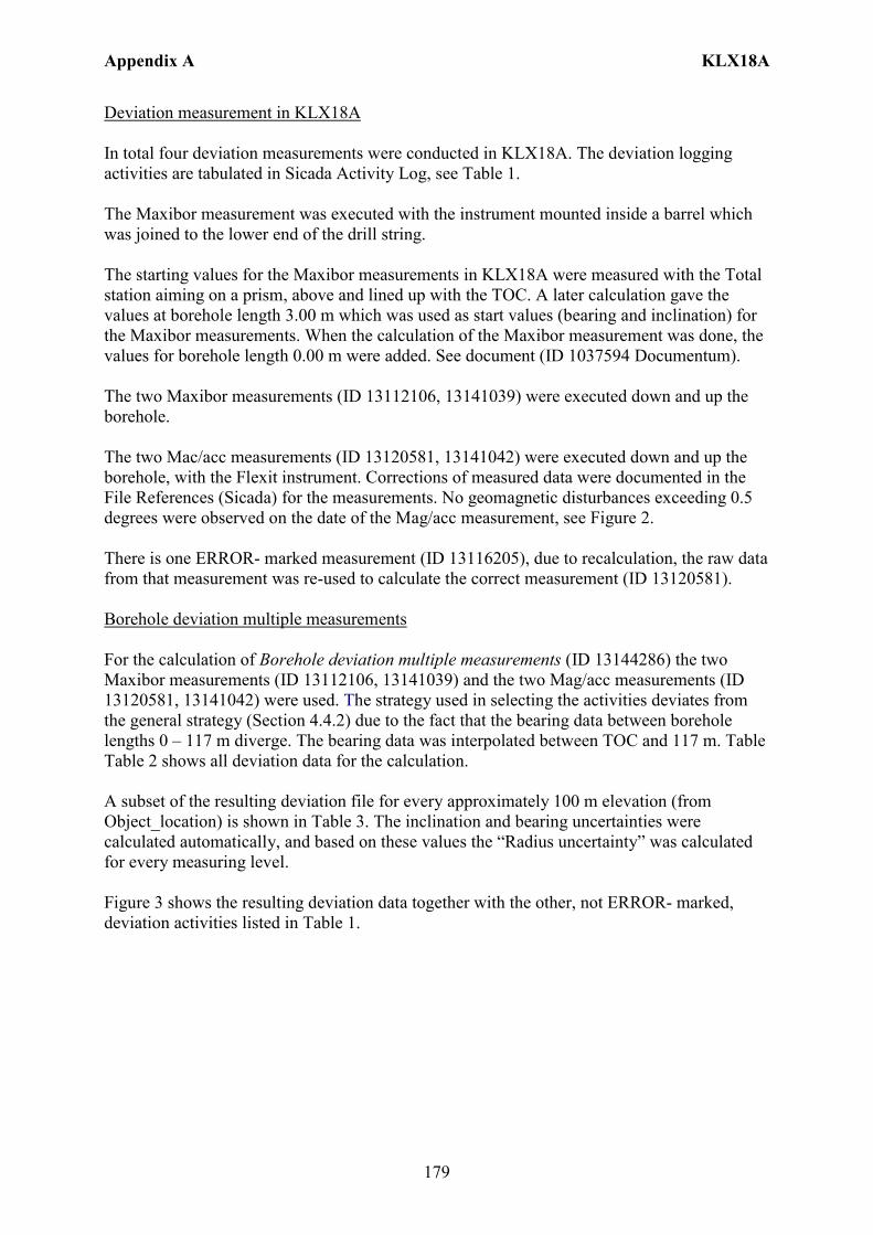
Appendix A KLX18A
179
Deviation measurement in KLX18A In total four deviation measurements were conducted in KLX18A. The deviation logging activities are tabulated in Sicada Activity Log, see Table 1. The Maxibor measurement was executed with the instrument mounted inside a barrel which was joined to the lower end of the drill string. The starting values for the Maxibor measurements in KLX18A were measured with the Total station aiming on a prism, above and lined up with the TOC. A later calculation gave the values at borehole length 3.00 m which was used as start values (bearing and inclination) for the Maxibor measurements. When the calculation of the Maxibor measurement was done, the values for borehole length 0.00 m were added. See document (ID 1037594 Documentum). The two Maxibor measurements (ID 13112106, 13141039) were executed down and up the borehole. The two Mac/acc measurements (ID 13120581, 13141042) were executed down and up the borehole, with the Flexit instrument. Corrections of measured data were documented in the File References (Sicada) for the measurements. No geomagnetic disturbances exceeding 0.5 degrees were observed on the date of the Mag/acc measurement, see Figure 2. There is one ERROR- marked measurement (ID 13116205), due to recalculation, the raw data from that measurement was re-used to calculate the correct measurement (ID 13120581). Borehole deviation multiple measurements For the calculation of Borehole deviation multiple measurements (ID 13144286) the two Maxibor measurements (ID 13112106, 13141039) and the two Mag/acc measurements (ID 13120581, 13141042) were used. The strategy used in selecting the activities deviates from the general strategy (Section 4.4.2) due to the fact that the bearing data between borehole lengths 0 – 117 m diverge. The bearing data was interpolated between TOC and 117 m. Table Table 2 shows all deviation data for the calculation. A subset of the resulting deviation file for every approximately 100 m elevation (from Object_location) is shown in Table 3. The inclination and bearing uncertainties were calculated automatically, and based on these values the “Radius uncertainty” was calculated for every measuring level. Figure 3 shows the resulting deviation data together with the other, not ERROR- marked, deviation activities listed in Table 1.
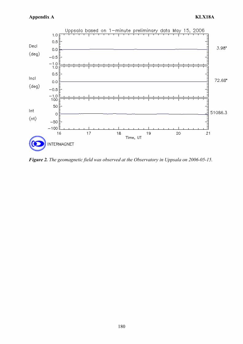
Appendix A KLX18A
180
Figure 2. The geomagnetic field was observed at the Observatory in Uppsala on 2006-05-15.
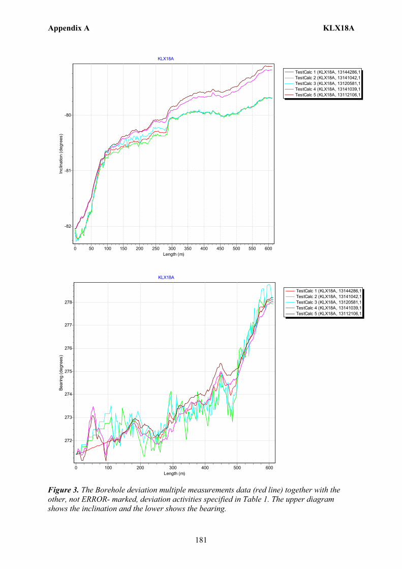
Appendix A KLX18A
181
TestCalc 1 (KLX18A, 13144286,1TestCalc 2 (KLX18A, 13141042,1TestCalc 3 (KLX18A, 13120581,1TestCalc 4 (KLX18A, 13141039,1TestCalc 5 (KLX18A, 13112106,1
KLX18A
Length (m)600550500450400350300250200150100500
Incl
inat
ion
(deg
rees
)
-80
-81
-82
TestCalc 1 (KLX18A, 13144286,1TestCalc 2 (KLX18A, 13141042,1TestCalc 3 (KLX18A, 13120581,1TestCalc 4 (KLX18A, 13141039,1TestCalc 5 (KLX18A, 13112106,1
KLX18A
Length (m)6005004003002001000
Bear
ing
(deg
rees
)
278
277
276
275
274
273
272
Figure 3. The Borehole deviation multiple measurements data (red line) together with the other, not ERROR- marked, deviation activities specified in Table 1. The upper diagram shows the inclination and the lower shows the bearing.
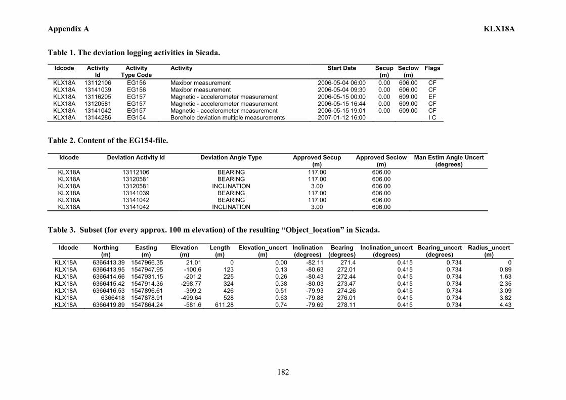
Appendix A KLX18A
182
Table 1. The deviation logging activities in Sicada.
Idcode Activity Id
Activity Type Code
Activity Start Date Secup(m)
Seclow(m)
Flags
KLX18A 13112106 EG156 Maxibor measurement 2006-05-04 06:00 0.00 606.00 CF KLX18A 13141039 EG156 Maxibor measurement 2006-05-04 09:30 0.00 606.00 CF KLX18A 13116205 EG157 Magnetic - accelerometer measurement 2006-05-15 00:00 0.00 609.00 EF KLX18A 13120581 EG157 Magnetic - accelerometer measurement 2006-05-15 16:44 0.00 609.00 CF KLX18A 13141042 EG157 Magnetic - accelerometer measurement 2006-05-15 19:01 0.00 609.00 CF KLX18A 13144286 EG154 Borehole deviation multiple measurements 2007-01-12 16:00 I C
Table 2. Content of the EG154-file.
Idcode Deviation Activity Id Deviation Angle Type Approved Secup (m)
Approved Seclow(m)
Man Estim Angle Uncert (degrees)
KLX18A 13112106 BEARING 117.00 606.00 KLX18A 13120581 BEARING 117.00 606.00 KLX18A 13120581 INCLINATION 3.00 606.00 KLX18A 13141039 BEARING 117.00 606.00 KLX18A 13141042 BEARING 117.00 606.00 KLX18A 13141042 INCLINATION 3.00 606.00
Table 3. Subset (for every approx. 100 m elevation) of the resulting “Object_location” in Sicada.
Idcode
Northing (m)
Easting (m)
Elevation (m)
Length (m)
Elevation_uncert(m)
Inclination (degrees)
Bearing (degrees)
Inclination_uncert(degrees)
Bearing_uncert(degrees)
Radius_uncert (m)
KLX18A 6366413.39 1547966.35 21.01 0 0.00 -82.11 271.4 0.415 0.734 0 KLX18A 6366413.95 1547947.95 -100.6 123 0.13 -80.63 272.01 0.415 0.734 0.89 KLX18A 6366414.66 1547931.15 -201.2 225 0.26 -80.43 272.44 0.415 0.734 1.63 KLX18A 6366415.42 1547914.36 -298.77 324 0.38 -80.03 273.47 0.415 0.734 2.35 KLX18A 6366416.53 1547896.61 -399.2 426 0.51 -79.93 274.26 0.415 0.734 3.09 KLX18A 6366418 1547878.91 -499.64 528 0.63 -79.88 276.01 0.415 0.734 3.82 KLX18A 6366419.89 1547864.24 -581.6 611.28 0.74 -79.69 278.11 0.415 0.734 4.43
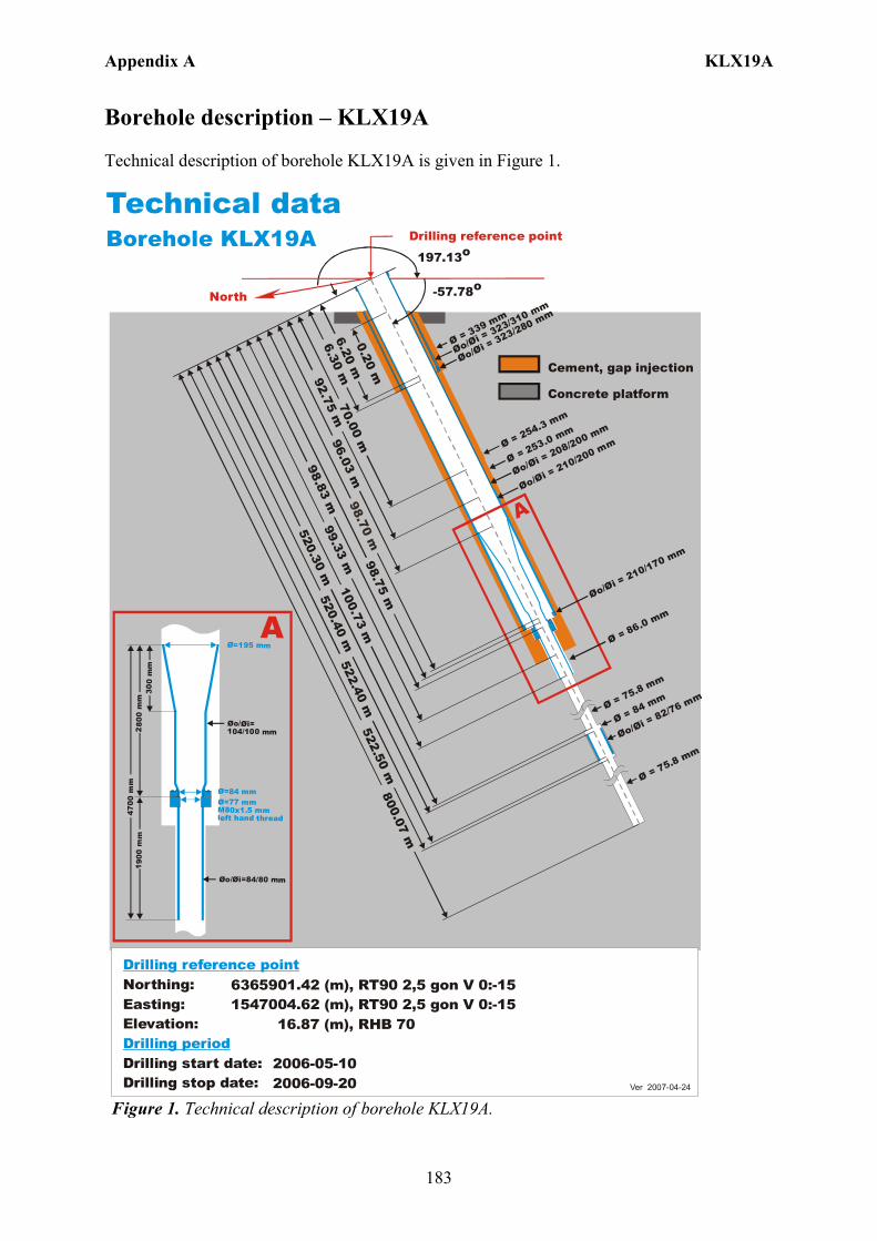
Appendix A KLX19A
183
Borehole description – KLX19A Technical description of borehole KLX19A is given in Figure 1.
6365901.42 (m),1547004.62 (m), 16.87 (m),
2006-05-10 2006-09-20
RT90 2,5 gon V 0:-15 RHB 70
RT90 2,5 gon V 0:-15Northing:Easting:Elevation:
Drilling start date:Drilling stop date:
Drilling reference point
Drilling period
Ver 2007-04-24
Technical dataBorehole KLX19A
Ø=195 mm
Øo/ =104/100 mm
Øi
Ø=84 mmØ=77 mm M80x1.5 mm left hand thread
Øo/ =84/80 mmØi
300
mm
280
0 m
m47
0 0 m
m1 9
00 m
m
A
Drilling reference point
North
197.13o
-57.78o
6.20 m
520.30 m520.40 m
522.40 m800.07 m
522.50 m
Cement, gap injection
Concrete platform
0.20 m
Øo/= 323/310 mm
Øi
Øo/= 323/280 mm
Øi
Øo/= 210/200 mm
Øi Øo/= 208/200 mm
Øi
Ø = 75.8 mm
Ø = 84 mm
Ø = 75.8 mm
A
Ø = 86.0 mm
98.70 m
6.30 m99.33 m
Ø = 339 mm
Ø = 253.0 mmØ = 254.3 mm
100.73 m98.75 m
98.83 m96.03 m
92.75 m70.00 m
Øo/= 210/170 mm
Øi
Øo/= 82/76 mm
Øi
Figure 1. Technical description of borehole KLX19A.
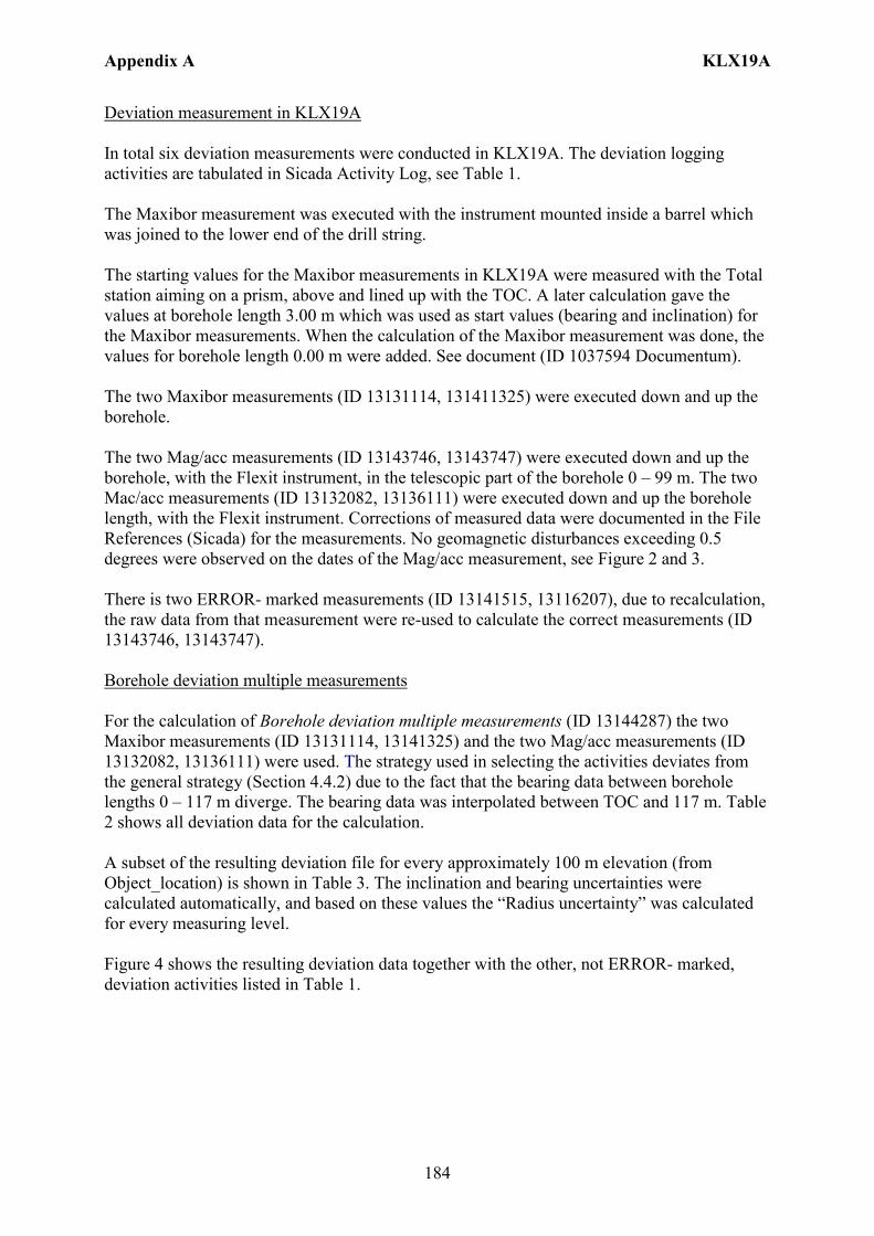
Appendix A KLX19A
184
Deviation measurement in KLX19A In total six deviation measurements were conducted in KLX19A. The deviation logging activities are tabulated in Sicada Activity Log, see Table 1. The Maxibor measurement was executed with the instrument mounted inside a barrel which was joined to the lower end of the drill string. The starting values for the Maxibor measurements in KLX19A were measured with the Total station aiming on a prism, above and lined up with the TOC. A later calculation gave the values at borehole length 3.00 m which was used as start values (bearing and inclination) for the Maxibor measurements. When the calculation of the Maxibor measurement was done, the values for borehole length 0.00 m were added. See document (ID 1037594 Documentum). The two Maxibor measurements (ID 13131114, 131411325) were executed down and up the borehole. The two Mag/acc measurements (ID 13143746, 13143747) were executed down and up the borehole, with the Flexit instrument, in the telescopic part of the borehole 0 – 99 m. The two Mac/acc measurements (ID 13132082, 13136111) were executed down and up the borehole length, with the Flexit instrument. Corrections of measured data were documented in the File References (Sicada) for the measurements. No geomagnetic disturbances exceeding 0.5 degrees were observed on the dates of the Mag/acc measurement, see Figure 2 and 3. There is two ERROR- marked measurements (ID 13141515, 13116207), due to recalculation, the raw data from that measurement were re-used to calculate the correct measurements (ID 13143746, 13143747). Borehole deviation multiple measurements For the calculation of Borehole deviation multiple measurements (ID 13144287) the two Maxibor measurements (ID 13131114, 13141325) and the two Mag/acc measurements (ID 13132082, 13136111) were used. The strategy used in selecting the activities deviates from the general strategy (Section 4.4.2) due to the fact that the bearing data between borehole lengths 0 – 117 m diverge. The bearing data was interpolated between TOC and 117 m. Table 2 shows all deviation data for the calculation. A subset of the resulting deviation file for every approximately 100 m elevation (from Object_location) is shown in Table 3. The inclination and bearing uncertainties were calculated automatically, and based on these values the “Radius uncertainty” was calculated for every measuring level. Figure 4 shows the resulting deviation data together with the other, not ERROR- marked, deviation activities listed in Table 1.
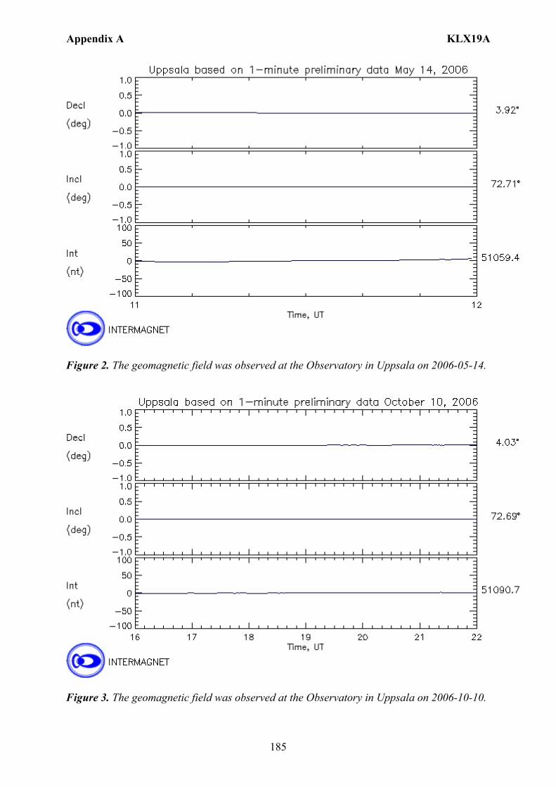
Appendix A KLX19A
185
Figure 2. The geomagnetic field was observed at the Observatory in Uppsala on 2006-05-14.
Figure 3. The geomagnetic field was observed at the Observatory in Uppsala on 2006-10-10.
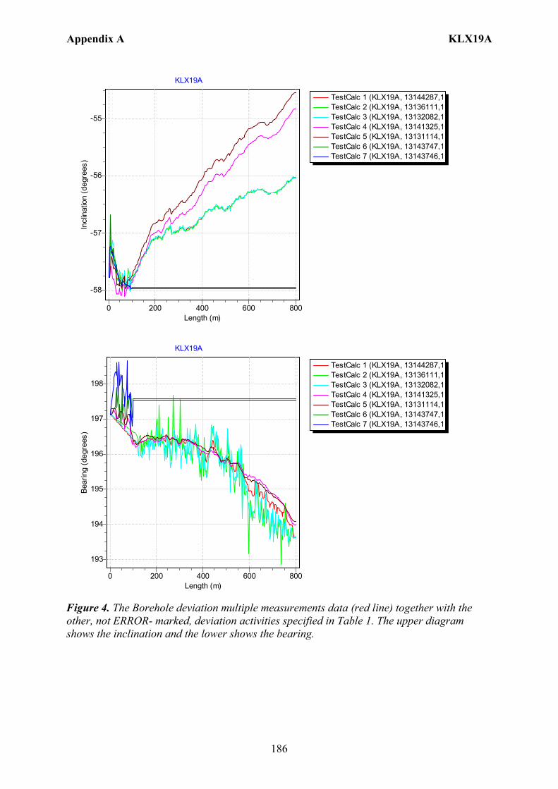
Appendix A KLX19A
186
TestCalc 1 (KLX19A, 13144287,1TestCalc 2 (KLX19A, 13136111,1TestCalc 3 (KLX19A, 13132082,1TestCalc 4 (KLX19A, 13141325,1TestCalc 5 (KLX19A, 13131114,1TestCalc 6 (KLX19A, 13143747,1TestCalc 7 (KLX19A, 13143746,1
KLX19A
Length (m)8006004002000
Incl
inat
ion
(deg
rees
)
-55
-56
-57
-58
TestCalc 1 (KLX19A, 13144287,1TestCalc 2 (KLX19A, 13136111,1TestCalc 3 (KLX19A, 13132082,1TestCalc 4 (KLX19A, 13141325,1TestCalc 5 (KLX19A, 13131114,1TestCalc 6 (KLX19A, 13143747,1TestCalc 7 (KLX19A, 13143746,1
KLX19A
Length (m)8006004002000
Bear
ing
(deg
rees
)
198
197
196
195
194
193
Figure 4. The Borehole deviation multiple measurements data (red line) together with the other, not ERROR- marked, deviation activities specified in Table 1. The upper diagram shows the inclination and the lower shows the bearing.
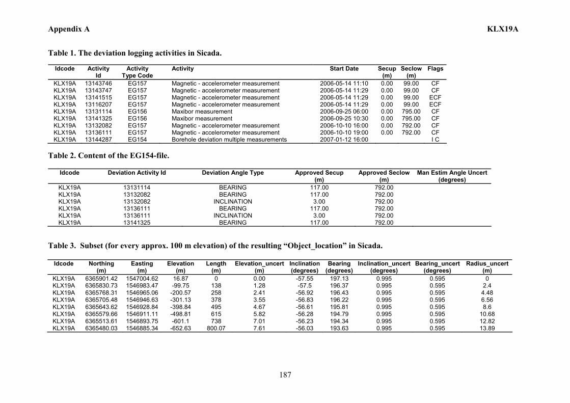
Appendix A KLX19A
187
Table 1. The deviation logging activities in Sicada.
Idcode Activity Id
Activity Type Code
Activity Start Date Secup(m)
Seclow(m)
Flags
KLX19A 13143746 EG157 Magnetic - accelerometer measurement 2006-05-14 11:10 0.00 99.00 CF KLX19A 13143747 EG157 Magnetic - accelerometer measurement 2006-05-14 11:29 0.00 99.00 CF KLX19A 13141515 EG157 Magnetic - accelerometer measurement 2006-05-14 11:29 0.00 99.00 ECF KLX19A 13116207 EG157 Magnetic - accelerometer measurement 2006-05-14 11:29 0.00 99.00 ECF KLX19A 13131114 EG156 Maxibor measurement 2006-09-25 06:00 0.00 795.00 CF KLX19A 13141325 EG156 Maxibor measurement 2006-09-25 10:30 0.00 795.00 CF KLX19A 13132082 EG157 Magnetic - accelerometer measurement 2006-10-10 16:00 0.00 792.00 CF KLX19A 13136111 EG157 Magnetic - accelerometer measurement 2006-10-10 19:00 0.00 792.00 CF KLX19A 13144287 EG154 Borehole deviation multiple measurements 2007-01-12 16:00 I C
Table 2. Content of the EG154-file.
Idcode Deviation Activity Id Deviation Angle Type Approved Secup (m)
Approved Seclow(m)
Man Estim Angle Uncert (degrees)
KLX19A 13131114 BEARING 117.00 792.00 KLX19A 13132082 BEARING 117.00 792.00 KLX19A 13132082 INCLINATION 3.00 792.00 KLX19A 13136111 BEARING 117.00 792.00 KLX19A 13136111 INCLINATION 3.00 792.00 KLX19A 13141325 BEARING 117.00 792.00
Table 3. Subset (for every approx. 100 m elevation) of the resulting “Object_location” in Sicada.
Idcode
Northing (m)
Easting (m)
Elevation (m)
Length (m)
Elevation_uncert(m)
Inclination (degrees)
Bearing (degrees)
Inclination_uncert(degrees)
Bearing_uncert(degrees)
Radius_uncert (m)
KLX19A 6365901.42 1547004.62 16.87 0 0.00 -57.55 197.13 0.995 0.595 0 KLX19A 6365830.73 1546983.47 -99.75 138 1.28 -57.5 196.37 0.995 0.595 2.4 KLX19A 6365768.31 1546965.06 -200.57 258 2.41 -56.92 196.43 0.995 0.595 4.48 KLX19A 6365705.48 1546946.63 -301.13 378 3.55 -56.83 196.22 0.995 0.595 6.56 KLX19A 6365643.62 1546928.84 -398.84 495 4.67 -56.61 195.81 0.995 0.595 8.6 KLX19A 6365579.66 1546911.11 -498.81 615 5.82 -56.28 194.79 0.995 0.595 10.68 KLX19A 6365513.61 1546893.75 -601.1 738 7.01 -56.23 194.34 0.995 0.595 12.82 KLX19A 6365480.03 1546885.34 -652.63 800.07 7.61 -56.03 193.63 0.995 0.595 13.89
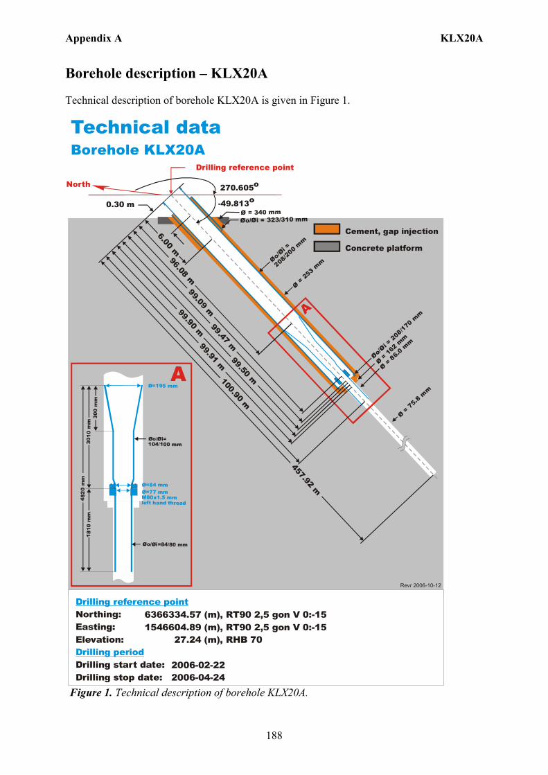
Appendix A KLX20A
188
Borehole description – KLX20A Technical description of borehole KLX20A is given in Figure 1. Technical dataBorehole KLX20A
6366334.57 (m),1546604.89 (m), 27.24 (m),
2006-02-22 2006-04-24
RT90 2,5 gon V 0:-15 RHB 70
RT90 2,5 gon V 0:-15Northing:Easting:Elevation:
Drilling start date:Drilling stop date:
Drilling reference point
Drilling period
North 270.605o
-49.813o
Drilling reference point
Cement, gap injection
Concrete platform
Ø=195 mm
Øo/ =104/100 mm
Øi
Ø=84 mmØ=77 mm M80x1.5 mm left hand thread
Øo/ =84/80 mmØi
300
mm
3010
mm
4 82
0 m
m1 8
10 m
m
A6.00 m
Øo/ = 323/310 mmØi
Øo/=
208/20
0 mm
Øi
Ø = 75
.8 m
m
A
0.30 m
Ø = 86.0
mm
99.47 m
96.08 m99.91 m
457.92 m
Ø = 340 mm
Ø = 253
mm
100.90 m99.50 m
Ø = 16
2 mm
99.90 m99.09 m
Revr 2006-10-12
Øo/= 2
08/170
mm
Øi
Figure 1. Technical description of borehole KLX20A.
Appendix A KLX20A
189
Deviation measurement in KLX20A In total four deviation measurements were conducted in KLX20A. The deviation logging activities are tabulated in Sicada Activity Log, see Table 1. The Maxibor measurement was executed with the instrument mounted inside a barrel which was joined to the lower end of the drill string. The starting values for the Maxibor measurements in KLX20A were measured with the Total station aiming on a prism, above and lined up with the TOC. A later calculation gave the values at borehole length 3.00 m which was used as start values (bearing and inclination) for the Maxibor measurements. When the calculation of the Maxibor measurement was done, the values for borehole length 0.00 m were added. See document (ID 1037594 Documentum). The two Maxibor measurements (ID 13114898, 13141381) were executed down and up the borehole. The two Mac/acc measurements (ID 13120027, 13141380) were executed down and up the borehole, with the Flexit instrument. Corrections of measured data were documented in the File References (Sicada) for the measurements. No geomagnetic disturbances exceeding 0.5 degrees were observed on the date of the Mag/acc measurement, see Figure 2. There is one ERROR- marked measurement (ID 13116206), due to recalculation, the raw data from that measurement were re-used to calculate the correct measurements (ID 13120027) Borehole deviation multiple measurements For the calculation of Borehole deviation multiple measurements (ID 13144288) the two Maxibor measurements (ID 13114898, 13141381) and the two Mag/acc measurements (ID 13120027, 13141380) were used. The strategy used in selecting the activities was in agreement with the general strategy (Section 4.4.2). Table 2 shows all deviation data for the calculation. A subset of the resulting deviation file for every approximately 100 m elevation (from Object_location) is shown in Table 3. The inclination and bearing uncertainties were calculated automatically, and based on these values the “Radius uncertainty” was calculated for every measuring level. Figure 3 shows the resulting deviation data together with the other, not ERROR- marked, deviation activities listed in Table 1.

Appendix A KLX20A
190
Figure 2. The geomagnetic field was observed at the Observatory in Uppsala on 2006-05-08.
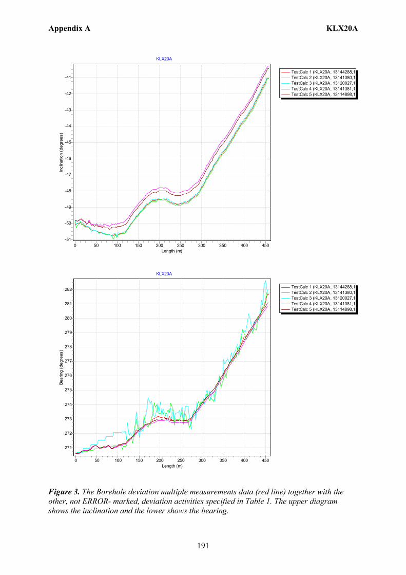
Appendix A KLX20A
191
TestCalc 1 (KLX20A, 13144288,1TestCalc 2 (KLX20A, 13141380,1TestCalc 3 (KLX20A, 13120027,1TestCalc 4 (KLX20A, 13141381,1TestCalc 5 (KLX20A, 13114898,1
KLX20A
Length (m)450400350300250200150100500
Incl
inat
ion
(deg
rees
)
-41
-42
-43
-44
-45
-46
-47
-48
-49
-50
-51
TestCalc 1 (KLX20A, 13144288,1TestCalc 2 (KLX20A, 13141380,1TestCalc 3 (KLX20A, 13120027,1TestCalc 4 (KLX20A, 13141381,1TestCalc 5 (KLX20A, 13114898,1
KLX20A
Length (m)450400350300250200150100500
Bear
ing
(deg
rees
)
282
281
280
279
278
277
276
275
274
273
272
271
Figure 3. The Borehole deviation multiple measurements data (red line) together with the other, not ERROR- marked, deviation activities specified in Table 1. The upper diagram shows the inclination and the lower shows the bearing.
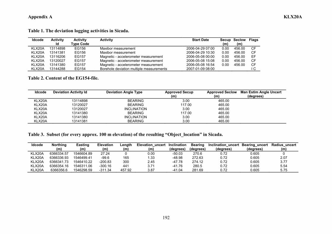
Appendix A KLX20A
192
Table 1. The deviation logging activities in Sicada.
Idcode Activity Id
Activity Type Code
Activity Start Date Secup(m)
Seclow(m)
Flags
KLX20A 13114898 EG156 Maxibor measurement 2006-04-29 07:00 0.00 456.00 CF KLX20A 13141381 EG156 Maxibor measurement 2006-04-29 10:30 0.00 456.00 CF KLX20A 13116206 EG157 Magnetic - accelerometer measurement 2006-05-08 00:00 0.00 456.00 EF KLX20A 13120027 EG157 Magnetic - accelerometer measurement 2006-05-08 15:08 0.00 456.00 CF KLX20A 13141380 EG157 Magnetic - accelerometer measurement 2006-05-08 16:54 0.00 456.00 CF KLX20A 13144288 EG154 Borehole deviation multiple measurements 2007-01-09 08:00 I C
Table 2. Content of the EG154-file.
Idcode Deviation Activity Id Deviation Angle Type Approved Secup (m)
Approved Seclow (m)
Man Estim Angle Uncert (degrees)
KLX20A 13114898 BEARING 3.00 465.00 KLX20A 13120027 BEARING 117.00 465.00 KLX20A 13120027 INCLINATION 3.00 465.00 KLX20A 13141380 BEARING 117.00 465.00 KLX20A 13141380 INCLINATION 3.00 465.00 KLX20A 13141381 BEARING 3.00 465.00
Table 3. Subset (for every approx. 100 m elevation) of the resulting “Object_location” in Sicada.
Idcode
Northing (m)
Easting (m)
Elevation (m)
Length (m)
Elevation_uncert(m)
Inclination (degrees)
Bearing (degrees)
Inclination_uncert(degrees)
Bearing_uncert(degrees)
Radius_uncert (m)
KLX20A 6366334.57 1546604.89 27.24 0 0.00 -50.03 270.6 0.72 0.605 0 KLX20A 6366336.93 1546499.41 -99.6 165 1.33 -48.98 272.63 0.72 0.605 2.07 KLX20A 6366341.73 1546410.22 -200.83 300 2.45 -47.78 274.12 0.72 0.605 3.77 KLX20A 6366354.16 1546311.06 -300.16 441 3.71 -41.76 280.5 0.72 0.605 5.54 KLX20A 6366356.6 1546298.59 -311.34 457.92 3.87 -41.04 281.69 0.72 0.605 5.75
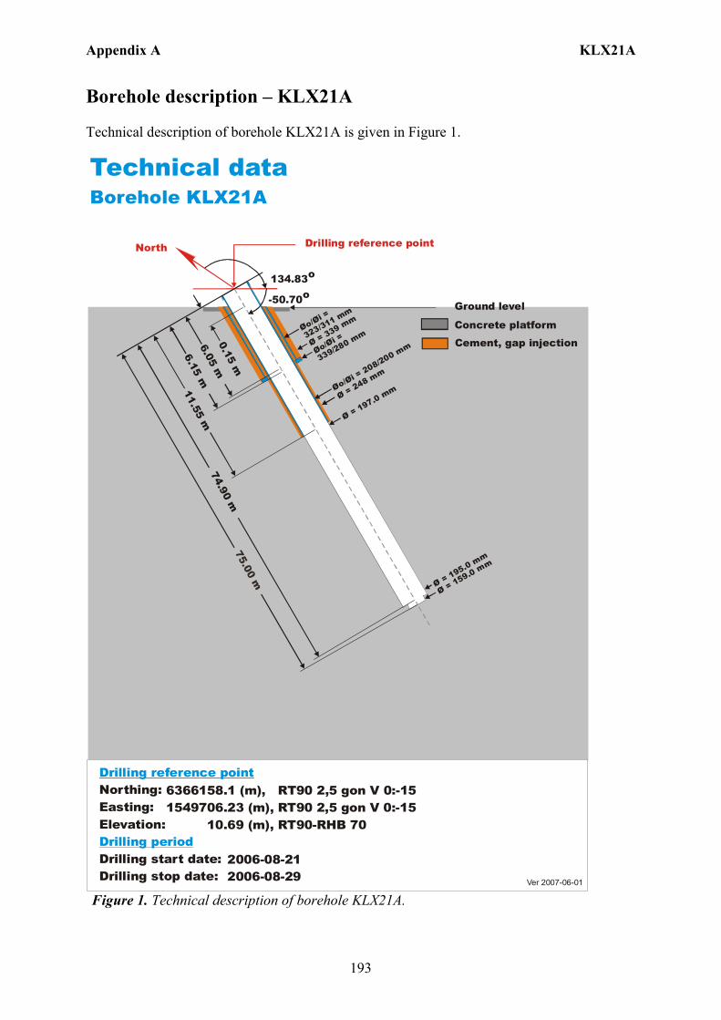
Appendix A KLX21A
193
Borehole description – KLX21A Technical description of borehole KLX21A is given in Figure 1.
6366158.1 (m),1549706.23 (m), 10.69 (m), 2006-08-21 2006-08-29
RT90 2,5 gon V 0:-15 RT90-RHB 70
RT90 2,5 gon V 0:-15Northing:Easting:Elevation:
Drilling start date:Drilling stop date:
Drilling reference point
Drilling period
Ver 2007-06-01
Technical dataBorehole KLX21A
Drilling reference point
Cement, gap injection
Concrete platform
Ground level
North
134.83o
-50.70o
Ø = 197.0 mm
Ø = 195.0 mm
Øo/=
323/311 mmØi
Øo/=
339/280 mmØi
Øo/= 208/200 mm
Øi
0.15 m
6.15 m6.05 m
Ø = 339 mm
74.90 m
Ø = 159.0 mm
11.55 m
Ø = 248 mm
Figure 1. Technical description of borehole KLX21A.

Appendix A KLX21A
194
Deviation measurement in KLX21A In total two deviation measurements were conducted in KLX21A. The deviation logging activities are tabulated in Sicada Activity Log, see Table 1. The two Mac/acc measurements (ID 13147165, 13147166) were executed down and up the borehole, with the Flexit instrument. Corrections of measured data were documented in the File References (Sicada) for the measurements. No geomagnetic disturbances exceeding 0.5 degrees were observed on the date of the Mag/acc measuring, see Figure 2. Borehole deviation multiple measurements For the calculation of Borehole deviation multiple measurements (ID 13150523) the two Mag/acc measurements (ID 13147165, 13147166) were used. Table 2 shows all deviation data for the calculation. A subset of the resulting deviation file for every approximately 100 m elevation (from Object_location) is shown in Table 3. The inclination and bearing uncertainties were calculated automatically, and based on these values the “Radius uncertainty” was calculated for every measuring level. Figure 3 shows the resulting deviation data together with the other, not ERROR- marked, deviation activities listed in Table 1.
Figure 2. The geomagnetic field was observed at the Observatory in Uppsala on 2007-02-01.
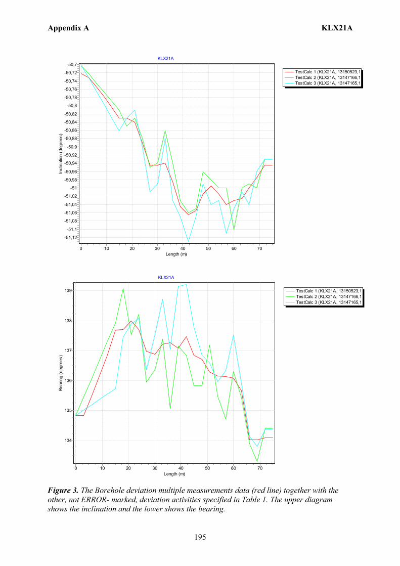
Appendix A KLX21A
195
TestCalc 1 (KLX21A, 13150523,1TestCalc 2 (KLX21A, 13147166,1TestCalc 3 (KLX21A, 13147165,1
KLX21A
Length (m)706050403020100
Incl
inat
ion
(deg
rees
)-50,7
-50,72
-50,74
-50,76
-50,78
-50,8
-50,82
-50,84
-50,86
-50,88
-50,9
-50,92
-50,94
-50,96
-50,98
-51
-51,02
-51,04
-51,06
-51,08
-51,1
-51,12
TestCalc 1 (KLX21A, 13150523,1TestCalc 2 (KLX21A, 13147166,1TestCalc 3 (KLX21A, 13147165,1
KLX21A
Length (m)706050403020100
Bear
ing
(deg
rees
)
139
138
137
136
135
134
Figure 3. The Borehole deviation multiple measurements data (red line) together with the other, not ERROR- marked, deviation activities specified in Table 1. The upper diagram shows the inclination and the lower shows the bearing.

Appendix A KLX21A
196
Table 1. The deviation logging activities in Sicada.
Idcode Activity Id
Activity Type Code
Activity Start Date Secup(m)
Seclow(m)
Flags
KLX21A 13147165 EG157 Magnetic - accelerometer measurement 2007-02-01 15:30 0.00 72.00 C KLX21A 13147166 EG157 Magnetic - accelerometer measurement 2007-02-01 15:45 0.00 72.00 C KLX21A 13150523 EG154 Borehole deviation multiple measurements 2007-02-27 10:00 I C
Table 2. Content of the EG154-file.
Idcode Deviation Activity Id Deviation Angle Type Approved Secup (m)
Approved Seclow (m)
Man Estim Angle Uncert (degrees)
KLX21A 13147165 BEARING 15.00 72.00 KLX21A 13147165 INCLINATION 3.00 73.00 KLX21A 13147166 BEARING 15.00 74.00 KLX21A 13147166 INCLINATION 3.00 75.00
Table 3. Subset (for every approx. 100 m elevation) of the resulting “Object_location” in Sicada.
Idcode
Northing (m)
Easting (m)
Elevation (m)
Length (m)
Elevation_uncert(m)
Inclination (degrees)
Bearing (degrees)
Inclination_uncert(degrees)
Bearing_uncert(degrees)
Radius_uncert (m)
KLX21A 6366158.18 1549706.23 10.69 0 0.00 -50.72 134.83 0.06 1.425 0 KLX21A 6366124.01 1549738.87 -47.54 75 0.05 -50.95 134.09 0.06 1.425 1.18
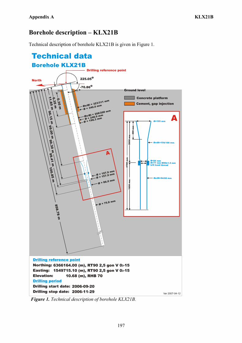
Appendix A KLX21B
197
Borehole description – KLX21B Technical description of borehole KLX21B is given in Figure 1.
6366164.00 (m),1549715.10 (m), 10.68 (m), 2006-09-20 2006-11-29
RT90 2,5 gon V 0:-15 RHB 70
RT90 2,5 gon V 0:-15Northing:Easting:Elevation:
Drilling start date:Drilling stop date:
Drilling reference point
Drilling period
Cement, gap injection
Concrete platform
Ver 2007-04-12
Technical dataBorehole KLX21B
North 225.05o
-70.86o
Drilling reference point
Ø = 198.3 mm
Ø = 197.9 mm
Øo/ = 323/311 mm
Øi
Øo/ = 208/200 mm
Øi
Ø = 75.8 mm
A
0.30 m
6.35 m
Ø = 340.0 mm
99.41 m96.15 m
99.00 m858.78 m
Ø = 157.9 mm
Ø = 86.0 mm
99.30 m100.85 m
11.85 m
Ø = 248.0 mm
Ø=195 mm
Øo/ =104/100 mmØi
Ø=84 mmØ=77 mm M80x1.5 mm left hand thread
Øo/ =84/80 mmØi
300
mm
2 850
mm
470
0 m
m1
850
mm
A
Ground level
Figure 1. Technical description of borehole KLX21B.
Appendix A KLX21B
198
Deviation measurement in KLX21B In total four deviation measurements were conducted in KLX21B. The deviation logging activities are tabulated in Sicada Activity Log, see Table 1. The Maxibor measurement was executed with the instrument mounted inside a barrel which was joined to the lower end of the drill string. The starting values for the Maxibor measurements in KLX21B were measured with the Total station aiming on a prism, above and lined up with the TOC. A later calculation gave the values at borehole length 3.00 m which was used as start values (bearing and inclination) for the Maxibor measurements. When the calculation of the Maxibor measurement was done, the values for borehole length 0.00 m were added. See document (ID 1037594 Documentum). The two Maxibor measurements (ID 13138801, 13138803) were executed down and up the borehole. The two Mac/acc measurements (ID 13144889, 13144890) were executed down and up the borehole, with the Flexit instrument. Corrections of measured data were documented in the File References (Sicada) for the measurements. No geomagnetic disturbances exceeding 0.5 degrees were observed on the date of the Mag/acc measurement, see Figure 2. Borehole deviation multiple measurements For the calculation of Borehole deviation multiple measurements (ID 13145644) the two Maxibor measurements (ID 13138801, 13138803) and the two Mag/acc measurements (ID 13144889, 13144890) were used. The file (ID 13145644) was ERROR-marked due to the fact that the bearing for both Mag/acc measurements were calculated from 3 m. This file was replaced with a new EG154- file (ID 13169280). The strategy used in selecting the activities was in agreement with the general strategy (Section 4.4.2). Table 2 shows all deviation data for the calculation. A subset of the resulting deviation file for every approximately 100 m elevation (from Object_location) is shown in Table 3. The inclination and bearing uncertainties were calculated automatically, and based on these values the “Radius uncertainty” was calculated for every measuring level. Figure 3 shows the resulting deviation data together with the other, not ERROR-marked, deviation activities listed in Table 1.

Appendix A KLX21B
199
Figure 2. The geomagnetic field was observed at the Observatory in Uppsala on 2007-01-04.
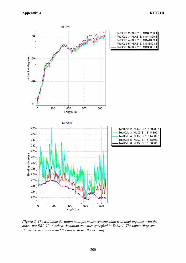
Appendix A KLX21B
200
TestCalc 2 (KLX21B, 13169280,1TestCalc 3 (KLX21B, 13144890,1TestCalc 4 (KLX21B, 13144889,1TestCalc 5 (KLX21B, 13138803,1TestCalc 6 (KLX21B, 13138801,1
KLX21B
Length (m)8006004002000
Incl
inat
ion
(deg
rees
)
-68
-69
-70
-71
TestCalc 2 (KLX21B, 13169280,1TestCalc 3 (KLX21B, 13144890,1TestCalc 4 (KLX21B, 13144889,1TestCalc 5 (KLX21B, 13138803,1TestCalc 6 (KLX21B, 13138801,1
KLX21B
Length (m)8006004002000
Bear
ing
(deg
rees
)
235
234
233
232
231
230
229
228
227
226
225
224
223
Figure 3. The Borehole deviation multiple measurements data (red line) together with the other, not ERROR- marked, deviation activities specified in Table 1. The upper diagram shows the inclination and the lower shows the bearing.
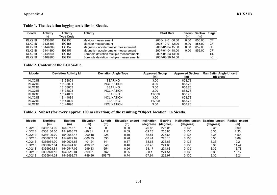
Appendix A KLX21B
201
Table 1. The deviation logging activities in Sicada.
Idcode Activity Id
Activity Type Code
Activity Start Date Secup(m)
Seclow(m)
Flags
KLX21B 13138801 EG156 Maxibor measurement 2006-12-01 06:00 0.00 855.00 CF KLX21B 13138803 EG156 Maxibor measurement 2006-12-01 12:00 0.00 855.00 CF KLX21B 13144889 EG157 Magnetic - accelerometer measurement 2007-01-04 15:00 0.00 852.00 CF KLX21B 13144890 EG157 Magnetic - accelerometer measurement 2007-01-04 18:00 0.00 852.00 CF KLX21B 13145644 EG154 Borehole deviation multiple measurements 2007-01-23 13:00 EC KLX21B 13169280 EG154 Borehole deviation multiple measurements 2007-08-20 14:00 I C
Table 2. Content of the EG154-file.
Idcode Deviation Activity Id Deviation Angle Type Approved Secup (m)
Approved Seclow(m)
Man Estim Angle Uncert (degrees)
KLX21B 13138801 BEARING 3.00 858.78 KLX21B 13138801 INCLINATION 3.00 858.78 KLX21B 13138803 BEARING 3.00 858.78 KLX21B 13138803 INCLINATION 3.00 858.78 KLX21B 13144889 BEARING 117.00 858.78 KLX21B 13144889 INCLINATION 3.00 858.78 KLX21B 13144890 BEARING 117.00 858.78 KLX21B 13144890 INCLINATION 3.00 858.78
Table 3. Subset (for every approx. 100 m elevation) of the resulting “Object_location” in Sicada.
Idcode
Northing (m)
Easting (m)
Elevation (m)
Length (m)
Elevation_uncert(m)
Inclination (degrees)
Bearing (degrees)
Inclination_uncert(degrees)
Bearing_uncert(degrees)
Radius_uncert (m)
KLX21B 6366164.00 1549715.10 10.68 0 0.00 -70.86 225.05 0.135 3.35 0.00 KLX21B 6366136.00 1549686.71 -99.31 117 0.09 -69.23 225.85 0.135 3.35 2.33 KLX21B 6366109.70 1549658.46 -200.18 225 0.19 -68.81 226.64 0.135 3.35 4.59 KLX21B 6366082.51 1549629.99 -300.75 333 0.28 -68.44 226.16 0.135 3.35 6.89 KLX21B 6366054.90 1549601.68 -401.24 441 0.37 -68.63 225.63 0.135 3.35 9.2 KLX21B 6366027.64 1549574.63 -498.97 546 0.46 -68.43 224.63 0.135 3.35 11.44 KLX21B 6365998.81 1549547.06 -599.33 654 0.56 -68.17 224.83 0.135 3.35 13.78 KLX21B 6365970.10 1549519.04 -699.61 762 0.65 -68.1 224.51 0.135 3.35 16.12 KLX21B 6365944.24 1549493.71 -789.36 858.78 0.74 -67.94 222.97 0.135 3.35 18.24
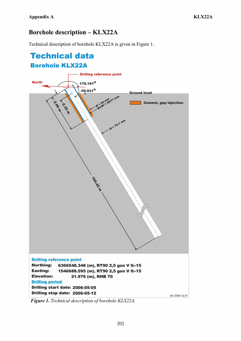
Appendix A KLX22A
202
Borehole description – KLX22A Technical description of borehole KLX22A is given in Figure 1.
6366548.348 (m), 1546688.595 (m), 21.976 (m), 2006-05-05 2006-05-12
RT90 2,5 gon V 0:-15 RHB 70
RT90 2,5 gon V 0:-15Northing:Easting:Elevation:
Drilling start date:Drilling stop date:
Drilling reference point
Drilling period
Cement, gap injection
Ver 2006-12-21
Technical dataBorehole KLX22A
179.191o
Drilling reference point
Øo/= 89/77 mm
Øi Ø = 96 mm
100.45 m
2.00 m0.30 m
Ø = 75.7 mm
Ground level-59.931o
North
Figure 1. Technical description of borehole KLX22A.

Appendix A KLX22A
203
Deviation measurement in KLX22A In total two deviation measurements were conducted in KLX22A. The deviation logging activities are tabulated in Sicada Activity Log, see Table 1. The two Mac/acc measurements (ID 13141470, 13118123) were executed down and up the borehole, with the Flexit instrument. Corrections of measured data were documented in the File References (Sicada) for the measurements. No geomagnetic disturbances exceeding 0.5 degrees were observed on the date of the Mag/acc measurement, see Figure 2. Borehole deviation multiple measurements For the calculation of Borehole deviation multiple measurements (ID 13144299) the two Mag/acc measurements (ID 13141470, 13118123) were used. Table 2 shows all deviation data for the calculation. A subset of the resulting deviation file for every approximately 100 m elevation (from Object_location) is shown in Table 3. The inclination and bearing uncertainties were calculated automatically, and based on these values the “Radius uncertainty” was calculated for every measuring level. Figure 3 shows the resulting deviation data together with the other, not ERROR- marked, deviation activities listed in Table 1.
Figure 2. The geomagnetic field was observed at the Observatory in Uppsala on 2006-07-05.
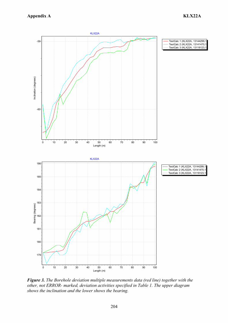
Appendix A KLX22A
204
TestCalc 1 (KLX22A, 13144299,1TestCalc 2 (KLX22A, 13141470,1TestCalc 3 (KLX22A, 13118123,1
KLX22A
Length (m)1009080706050403020100
Incl
inat
ion
(deg
rees
)
-59
-60
TestCalc 1 (KLX22A, 13144299,1TestCalc 2 (KLX22A, 13141470,1TestCalc 3 (KLX22A, 13118123,1
KLX22A
Length (m)1009080706050403020100
Bear
ing
(deg
rees
)
186
185
184
183
182
181
180
179
Figure 3. The Borehole deviation multiple measurements data (red line) together with the other, not ERROR- marked, deviation activities specified in Table 1. The upper diagram shows the inclination and the lower shows the bearing.

Appendix A KLX22A
205
Table 1. The deviation logging activities in Sicada.
Idcode Activity Id
Activity Type Code
Activity Start Date Secup(m)
Seclow(m)
Flags
KLX22A 13118123 EG157 Magnetic - accelerometer measurement 2006-07-05 14:32 0.00 99.00 CF KLX22A 13141470 EG157 Magnetic - accelerometer measurement 2006-07-05 14:46 0.00 99.00 CF KLX22A 13144299 EG154 Borehole deviation multiple measurements 2007-01-09 08:00 I C
Table 2. Content of the EG154-file.
Idcode Deviation Activity Id Deviation Angle Type Approved Secup (m)
Approved Seclow (m)
Man Estim Angle Uncert (degrees)
KLX22A 13118123 BEARING 18.00 100.45 KLX22A 13118123 INCLINATION 3.00 100.45 KLX22A 13141470 BEARING 18.00 100.45 KLX22A 13141470 INCLINATION 3.00 100.45
Table 3. Subset (for every approx. 100 m elevation) of the resulting “Object_location” in Sicada.
Idcode
Northing (m)
Easting (m)
Elevation (m)
Length (m)
Elevation_uncert(m)
Inclination (degrees)
Bearing (degrees)
Inclination_uncert(degrees)
Bearing_uncert(degrees)
Radius_uncert (m)
KLX22A 6366548.35 1546688.6 21.97 0 0.00 -60.34 179.19 0.151 0.666 0 KLX22A 6366497.19 1546686.79 -64.44 100.45 0.14 -58.95 185.8 0.151 0.666 0.6
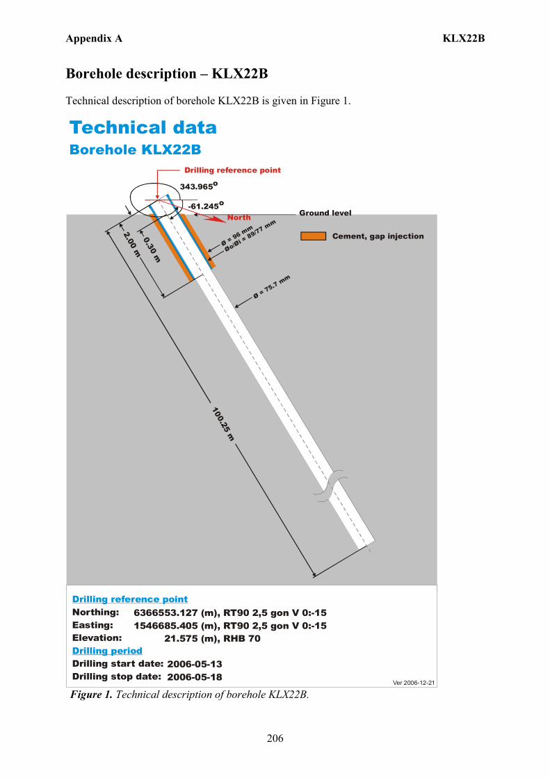
Appendix A KLX22B
206
Borehole description – KLX22B Technical description of borehole KLX22B is given in Figure 1.
6366553.127 (m), 1546685.405 (m), 21.575 (m), 2006-05-13 2006-05-18
RT90 2,5 gon V 0:-15 RHB 70
RT90 2,5 gon V 0:-15Northing:Easting:Elevation:
Drilling start date:Drilling stop date:
Drilling reference point
Drilling period
Cement, gap injection
Ver 2006-12-21
Technical dataBorehole KLX22B
343.965oDrilling reference point
Øo/= 89/77 mm
Øi Ø = 96 mm
100.25 m
2.00 m0.30 m
Ø = 75.7 mm
Ground level-61.245o
North
Figure 1. Technical description of borehole KLX22B.

Appendix A KLX22B
207
Deviation measurement in KLX22B In total two deviation measurements were conducted in KLX22B. The deviation logging activities are tabulated in Sicada Activity Log, see Table 1. The two Mac/acc measurements (ID 13141479, 13118124) were executed down and up the borehole, with the Flexit instrument. Corrections of measured data were documented in the File References (Sicada) for the measurements. No geomagnetic disturbances exceeding 0.5 degrees were observed on the date of the Mag/acc measurement, see Figure 2. Borehole deviation multiple measurements For the calculation of Borehole deviation multiple measurements (ID 13144289) the two Mag/acc measurements (ID 13141479, 13118124) were used. Table 2 shows all deviation data for the calculation. A subset of the resulting deviation file for every approximately 100 m elevation (from Object_location) is shown in Table 3. The inclination and bearing uncertainties were calculated automatically, and based on these values the “Radius uncertainty” was calculated for every measuring level. Figure 3 shows the resulting deviation data together with the other, not ERROR- marked, deviation activities listed in Table 1.
Figure 2. The geomagnetic field was observed at the Observatory in Uppsala on 2006-07-05.
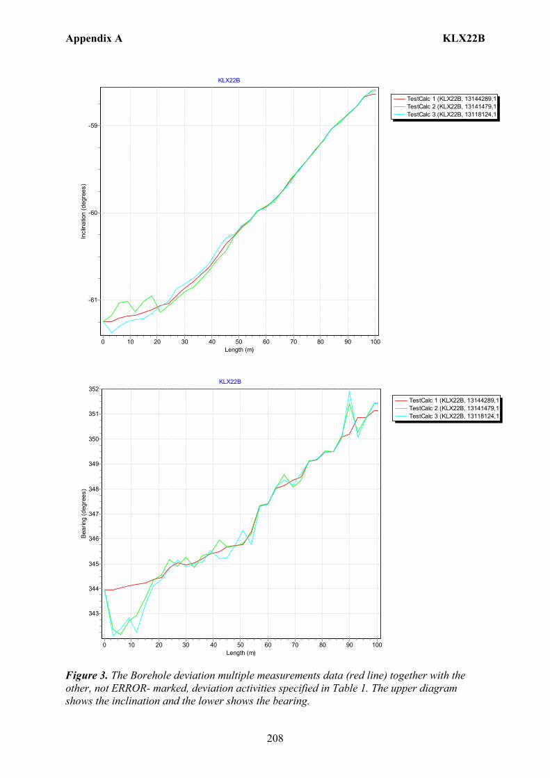
Appendix A KLX22B
208
TestCalc 1 (KLX22B, 13144289,1TestCalc 2 (KLX22B, 13141479,1TestCalc 3 (KLX22B, 13118124,1
KLX22B
Length (m)1009080706050403020100
Incl
inat
ion
(deg
rees
)
-59
-60
-61
TestCalc 1 (KLX22B, 13144289,1TestCalc 2 (KLX22B, 13141479,1TestCalc 3 (KLX22B, 13118124,1
KLX22B
Length (m)1009080706050403020100
Bear
ing
(deg
rees
)
352
351
350
349
348
347
346
345
344
343
Figure 3. The Borehole deviation multiple measurements data (red line) together with the other, not ERROR- marked, deviation activities specified in Table 1. The upper diagram shows the inclination and the lower shows the bearing.
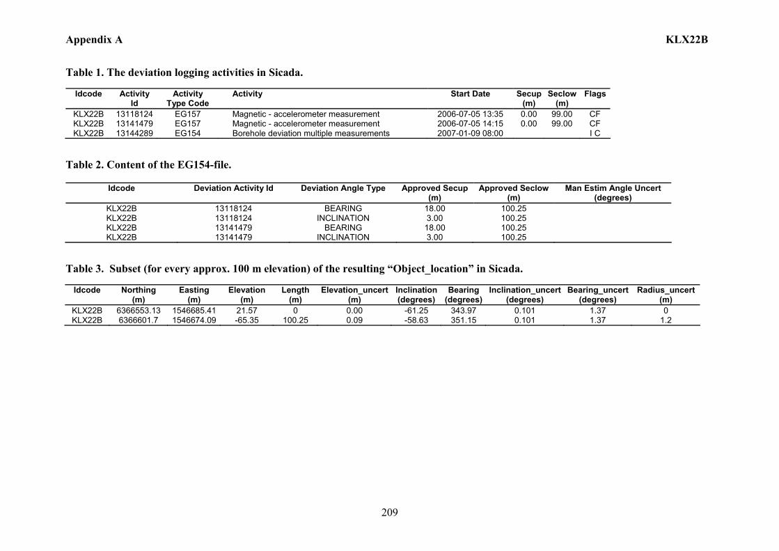
Appendix A KLX22B
209
Table 1. The deviation logging activities in Sicada.
Idcode Activity Id
Activity Type Code
Activity Start Date Secup(m)
Seclow(m)
Flags
KLX22B 13118124 EG157 Magnetic - accelerometer measurement 2006-07-05 13:35 0.00 99.00 CF KLX22B 13141479 EG157 Magnetic - accelerometer measurement 2006-07-05 14:15 0.00 99.00 CF KLX22B 13144289 EG154 Borehole deviation multiple measurements 2007-01-09 08:00 I C
Table 2. Content of the EG154-file.
Idcode Deviation Activity Id Deviation Angle Type Approved Secup (m)
Approved Seclow (m)
Man Estim Angle Uncert (degrees)
KLX22B 13118124 BEARING 18.00 100.25 KLX22B 13118124 INCLINATION 3.00 100.25 KLX22B 13141479 BEARING 18.00 100.25 KLX22B 13141479 INCLINATION 3.00 100.25
Table 3. Subset (for every approx. 100 m elevation) of the resulting “Object_location” in Sicada.
Idcode
Northing (m)
Easting (m)
Elevation (m)
Length (m)
Elevation_uncert(m)
Inclination (degrees)
Bearing (degrees)
Inclination_uncert(degrees)
Bearing_uncert(degrees)
Radius_uncert (m)
KLX22B 6366553.13 1546685.41 21.57 0 0.00 -61.25 343.97 0.101 1.37 0 KLX22B 6366601.7 1546674.09 -65.35 100.25 0.09 -58.63 351.15 0.101 1.37 1.2
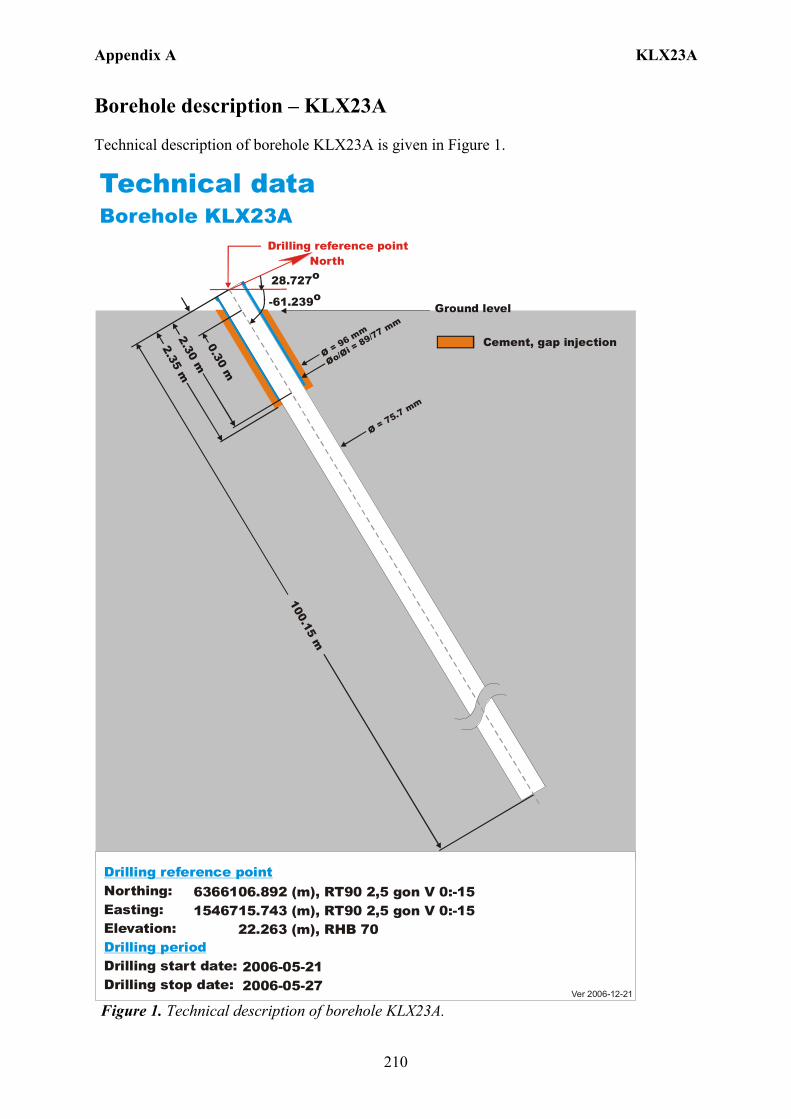
Appendix A KLX23A
210
Borehole description – KLX23A Technical description of borehole KLX23A is given in Figure 1.
6366106.892 (m), 1546715.743 (m), 22.263 (m), 2006-05-21 2006-05-27
RT90 2,5 gon V 0:-15 RHB 70
RT90 2,5 gon V 0:-15Northing:Easting:Elevation:
Drilling start date:Drilling stop date:
Drilling reference point
Drilling period
Cement, gap injection
Ver 2006-12-21
Technical dataBorehole KLX23A
28.727o
Drilling reference point
Øo/= 89/77 mm
Øi Ø = 96 mm
100.15 m
2.30 m0.30 m
Ø = 75.7 mm
Ground level-61.239o
North
2.35 m
Figure 1. Technical description of borehole KLX23A.

Appendix A KLX23A
211
Deviation measurement in KLX23A In total two deviation measurements were conducted in KLX23A. The deviation logging activities are tabulated in Sicada Activity Log, see Table 1. The two Mac/acc measurements (ID 13141481, 13118125) were executed down and up the borehole, with the Flexit instrument. Corrections of measured data were documented in the File References (Sicada) for the measurements. No geomagnetic disturbances exceeding 0.5 degrees were observed on the date of the Mag/acc measurement, see Figure 2. Borehole deviation multiple measurements For the calculation of Borehole deviation multiple measurements (ID 13144290) the two Mag/acc measurements (ID 13141481, 13118125) were used. Table 2 shows all deviation data for the calculation. A subset of the resulting deviation file for every approximately 100 m elevation (from Object_location) is shown in Table 3. The inclination and bearing uncertainties were calculated automatically, and based on these values the “Radius uncertainty” was calculated for every measuring level. Figure 3 shows the resulting deviation data together with the other, not ERROR- marked, deviation activities listed in Table 1.
Figure 2. The geomagnetic field was observed at the Observatory in Uppsala on 2006-07-05.

Appendix A KLX23A
212
TestCalc 1 (KLX23A, 13144290,1TestCalc 2 (KLX23A, 13141481,1TestCalc 3 (KLX23A, 13118125,1
KLX23A
Length (m)1009080706050403020100
Incl
inat
ion
(deg
rees
)
-59
-60
-61
TestCalc 1 (KLX23A, 13144290,1TestCalc 2 (KLX23A, 13141481,1TestCalc 3 (KLX23A, 13118125,1
KLX23A
Length (m)1009080706050403020100
Bear
ing
(deg
rees
)
34
33
32
31
30
29
Figure 3. The Borehole deviation multiple measurements data (red line) together with the other, not ERROR- marked, deviation activities specified in Table 1. The upper diagram shows the inclination and the lower shows the bearing.

213
Table 1. The deviation logging activities in Sicada.
Idcode Activity Id
Activity Type Code
Activity Start Date Secup(m)
Seclow(m)
Flags
KLX23A 13118125 EG157 Magnetic - accelerometer measurement 2006-07-05 17:56 0.00 99.00 CF KLX23A 13141481 EG157 Magnetic - accelerometer measurement 2006-07-05 18:15 0.00 99.00 CF KLX23A 13144290 EG154 Borehole deviation multiple measurements 2007-01-09 08:00 I C
Table 2. Content of the EG154-file.
Idcode Deviation Activity Id Deviation Angle Type Approved Secup (m)
Approved Seclow (m)
Man Estim Angle Uncert (degrees)
KLX23A 13118125 BEARING 18.00 100.15 KLX23A 13118125 INCLINATION 3.00 100.15 KLX23A 13141481 BEARING 18.00 100.15 KLX23A 13141481 INCLINATION 3.00 100.15
Table 3. Subset (for every approx. 100 m elevation) of the resulting “Object_location” in Sicada.
Idcode
Northing (m)
Easting (m)
Elevation (m)
Length (m)
Elevation_uncert(m)
Inclination (degrees)
Bearing (degrees)
Inclination_uncert(degrees)
Bearing_uncert(degrees)
Radius_uncert (m)
KLX23A 6366106.89 1546715.74 22.26 0 0.00 -61.36 28.73 0.08 0.482 0 KLX23A 6366149.56 1546741.92 -64.46 100.15 0.07 -58.47 33.73 0.08 0.482 0.42
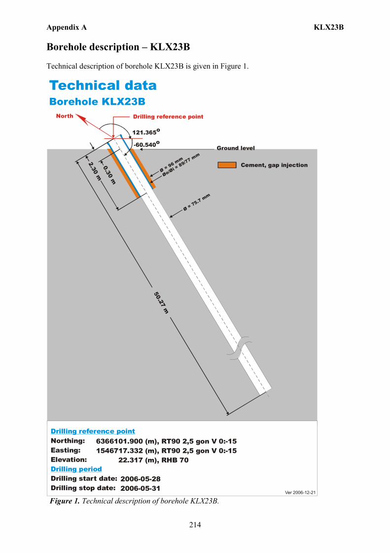
Appendix A KLX23B
214
Borehole description – KLX23B Technical description of borehole KLX23B is given in Figure 1.
6366101.900 (m), 1546717.332 (m), 22.317 (m), 2006-05-28 2006-05-31
RT90 2,5 gon V 0:-15 RHB 70
RT90 2,5 gon V 0:-15Northing:Easting:Elevation:
Drilling start date:Drilling stop date:
Drilling reference point
Drilling period
Cement, gap injection
Ver 2006-12-21
Technical dataBorehole KLX23B
121.365o
Drilling reference point
Øo/= 89/77 m
m
Øi Ø = 96 mm
50.27 m
2.30 m0.30 m
Ø = 75.7 mm
Ground level-60.540o
North
Figure 1. Technical description of borehole KLX23B.
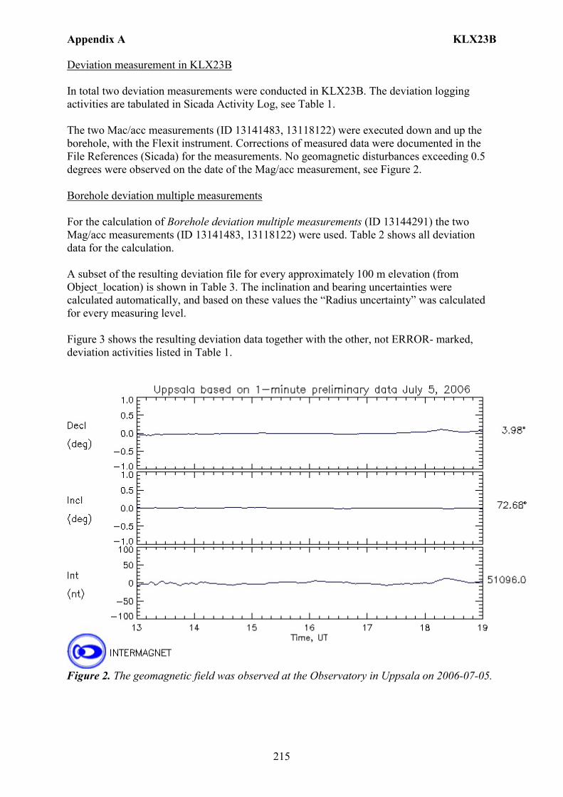
Appendix A KLX23B
215
Deviation measurement in KLX23B In total two deviation measurements were conducted in KLX23B. The deviation logging activities are tabulated in Sicada Activity Log, see Table 1. The two Mac/acc measurements (ID 13141483, 13118122) were executed down and up the borehole, with the Flexit instrument. Corrections of measured data were documented in the File References (Sicada) for the measurements. No geomagnetic disturbances exceeding 0.5 degrees were observed on the date of the Mag/acc measurement, see Figure 2. Borehole deviation multiple measurements For the calculation of Borehole deviation multiple measurements (ID 13144291) the two Mag/acc measurements (ID 13141483, 13118122) were used. Table 2 shows all deviation data for the calculation. A subset of the resulting deviation file for every approximately 100 m elevation (from Object_location) is shown in Table 3. The inclination and bearing uncertainties were calculated automatically, and based on these values the “Radius uncertainty” was calculated for every measuring level. Figure 3 shows the resulting deviation data together with the other, not ERROR- marked, deviation activities listed in Table 1.
Figure 2. The geomagnetic field was observed at the Observatory in Uppsala on 2006-07-05.

Appendix A KLX23B
216
TestCalc 1 (KLX23B, 13144291,1TestCalc 2 (KLX23B, 13141483,1TestCalc 3 (KLX23B, 13118122,1
KLX23B
Length (m)50454035302520151050
Incl
inat
ion
(deg
rees
)
-60
TestCalc 1 (KLX23B, 13144291,1TestCalc 2 (KLX23B, 13141483,1TestCalc 3 (KLX23B, 13118122,1
KLX23B
Length (m)50454035302520151050
Bear
ing
(deg
rees
)
122
121
Figure 3. The Borehole deviation multiple measurements data (red line) together with the other, not ERROR- marked, deviation activities specified in Table 1. The upper diagram shows the inclination and the lower shows the bearing.
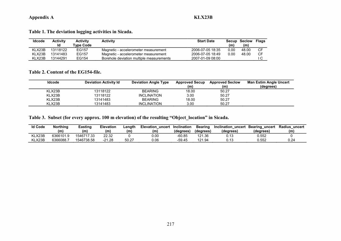
Appendix A KLX23B
217
Table 1. The deviation logging activities in Sicada.
Idcode Activity Id
Activity Type Code
Activity Start Date Secup(m)
Seclow(m)
Flags
KLX23B 13118122 EG157 Magnetic - accelerometer measurement 2006-07-05 18:35 0.00 48.00 CF KLX23B 13141483 EG157 Magnetic - accelerometer measurement 2006-07-05 18:49 0.00 48.00 CF KLX23B 13144291 EG154 Borehole deviation multiple measurements 2007-01-09 08:00 I C
Table 2. Content of the EG154-file.
Idcode Deviation Activity Id Deviation Angle Type Approved Secup (m)
Approved Seclow (m)
Man Estim Angle Uncert (degrees)
KLX23B 13118122 BEARING 18.00 50.27 KLX23B 13118122 INCLINATION 3.00 50.27 KLX23B 13141483 BEARING 18.00 50.27 KLX23B 13141483 INCLINATION 3.00 50.27
Table 3. Subset (for every approx. 100 m elevation) of the resulting “Object_location” in Sicada.
Id Code
Northing (m)
Easting (m)
Elevation (m)
Length (m)
Elevation_uncert(m)
Inclination (degrees)
Bearing (degrees)
Inclination_uncert(degrees)
Bearing_uncert(degrees)
Radius_uncert (m)
KLX23B 6366101.9 1546717.33 22.32 0 0.00 -60.85 121.36 0.13 0.552 0 KLX23B 6366088.7 1546738.58 -21.28 50.27 0.06 -59.45 121.94 0.13 0.552 0.24
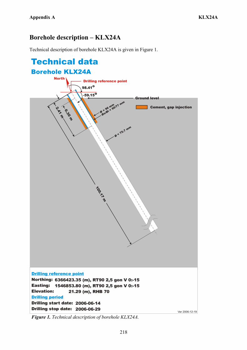
Appendix A KLX24A
218
Borehole description – KLX24A Technical description of borehole KLX24A is given in Figure 1.
6366423.35 (m),1546853.80 (m), 21.29 (m), 2006-06-14 2006-06-29
RT90 2,5 gon V 0:-15 RHB 70
RT90 2,5 gon V 0:-15Northing:Easting:Elevation:
Drilling start date:Drilling stop date:
Drilling reference point
Drilling period
Cement, gap injection
Ver 2006-12-19
Technical dataBorehole KLX24A
North
98.41o
-59.15o
Drilling reference point
Øo/= 90/77 mm
Øi Ø = 96 mm
100.17 m
2.41 m0.30 m
Ø = 75.7 mm
Ground level
Figure 1. Technical description of borehole KLX24A.

Appendix A KLX24A
219
Deviation measurement in KLX24A In total two deviation measurements were conducted in KLX24A. The deviation logging activities are tabulated in Sicada Activity Log, see Table 1. The two Mac/acc measurements (ID 13141485, 13119008) were executed down and up the borehole, with the Flexit instrument. Corrections of measured data were documented in the File References (Sicada) for the measurements. No geomagnetic disturbances exceeding 0.5 degrees were observed on the date of the Mag/acc measurement, see Figure 2. Borehole deviation multiple measurements For the calculation of Borehole deviation multiple measurements (ID 13144292) the two Mag/acc measurements (ID 13141485, 13119008) were used. Table 2 shows all deviation data for the calculation. A subset of the resulting deviation file for every approximately 100 m elevation (from Object_location) is shown in Table 3. The inclination and bearing uncertainties were calculated automatically, and based on these values the “Radius uncertainty” was calculated for every measuring level. Figure 3 shows the resulting deviation data together with the other, not ERROR- marked, deviation activities listed in Table 1.
Figure 2. The geomagnetic field was observed at the Observatory in Uppsala on 2006-08-11.

Appendix A KLX24A
220
TestCalc 1 (KLX24A, 13144292,1TestCalc 2 (KLX24A, 13141485,1TestCalc 3 (KLX24A, 13119008,1
KLX24A
Length (m)1009080706050403020100
Incl
inat
ion
(deg
rees
)
-57
-58
-59
TestCalc 1 (KLX24A, 13144292,1TestCalc 2 (KLX24A, 13141485,1TestCalc 3 (KLX24A, 13119008,1
KLX24A
Length (m)1009080706050403020100
Bear
ing
(deg
rees
)
100
99
98
Figure 3. The Borehole deviation multiple measurements data (red line) together with the other, not ERROR- marked, deviation activities specified in Table 1. The upper diagram shows the inclination and the lower shows the bearing.

Appendix A KLX24A
221
Table 1. The deviation logging activities in Sicada.
Idcode Activity Id
Activity Type Code
Activity Start Date Secup(m)
Seclow(m)
Flags
KLX24A 13119008 EG157 Magnetic - accelerometer measurement 2006-08-11 17:52 0.00 99.00 CF KLX24A 13141485 EG157 Magnetic - accelerometer measurement 2006-08-11 18:08 0.00 99.00 CF KLX24A 13144292 EG154 Borehole deviation multiple measurements 2007-01-09 08:00 I C
Table 2. Content of the EG154-file.
Idcode Deviation Activity Id Deviation Angle Type Approved Secup (m)
Approved Seclow (m)
Man Estim Angle Uncert (degrees)
KLX24A 13119008 BEARING 18.00 100.17 KLX24A 13119008 INCLINATION 3.00 100.17 KLX24A 13141485 BEARING 18.00 100.17 KLX24A 13141485 INCLINATION 3.00 100.17
Table 3. Subset (for every approx. 100 m elevation) of the resulting “Object_location” in Sicada.
Idcode
Northing (m)
Easting (m)
Elevation (m)
Length (m)
Elevation_uncert(m)
Inclination (degrees)
Bearing (degrees)
Inclination_uncert(degrees)
Bearing_uncert(degrees)
Radius_uncert (m)
KLX24A 6366423.35 1546853.8 21.29 0 0.00 -59.15 98.41 0.071 0.829 0 KLX24A 6366415.16 1546906.19 -63.68 100.17 0.07 -56.6 99.73 0.071 0.829 0.77

Appendix A KLX25A
222
Borehole description – KLX25A Technical description of borehole KLX25A is given in Figure 1.
6366274.74 (m),1546769.66 (m), 22.84 (m), 2006-07-01 2006-07-04
RT90 2,5 gon V 0:-15 RHB 70
RT90 2,5 gon V 0:-15Northing:Easting:Elevation:
Drilling start date:Drilling stop date:
Drilling reference point
Drilling period
Cement, gap injection
Ver 2006-12-19
Technical dataBorehole KLX25A
North
-59.46o
Drilling reference point
Øo/= 90/77 mm
Øi Ø = 96 mm
50.24 m
2.20 m0.30 m
Ø = 75.7 mm
Ground level
145.73o
Figure 1. Technical description of borehole KLX25A.
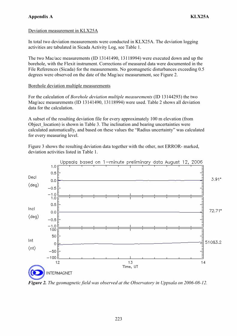
Appendix A KLX25A
223
Deviation measurement in KLX25A In total two deviation measurements were conducted in KLX25A. The deviation logging activities are tabulated in Sicada Activity Log, see Table 1. The two Mac/acc measurements (ID 13141490, 13118994) were executed down and up the borehole, with the Flexit instrument. Corrections of measured data were documented in the File References (Sicada) for the measurements. No geomagnetic disturbances exceeding 0.5 degrees were observed on the date of the Mag/acc measurument, see Figure 2. Borehole deviation multiple measurements For the calculation of Borehole deviation multiple measurements (ID 13144293) the two Mag/acc measurements (ID 13141490, 13118994) were used. Table 2 shows all deviation data for the calculation. A subset of the resulting deviation file for every approximately 100 m elevation (from Object_location) is shown in Table 3. The inclination and bearing uncertainties were calculated automatically, and based on these values the “Radius uncertainty” was calculated for every measuring level. Figure 3 shows the resulting deviation data together with the other, not ERROR- marked, deviation activities listed in Table 1.
Figure 2. The geomagnetic field was observed at the Observatory in Uppsala on 2006-08-12.

Appendix A KLX25A
224
TestCalc 1 (KLX25A, 13144293,1TestCalc 2 (KLX25A, 13141490,1TestCalc 3 (KLX25A, 13118994,1
KLX25A
Length (m)50454035302520151050
Incl
inat
ion
(deg
rees
)
-59
TestCalc 1 (KLX25A, 13144293,1TestCalc 2 (KLX25A, 13141490,1TestCalc 3 (KLX25A, 13118994,1
KLX25A
Length (m)50454035302520151050
Bear
ing
(deg
rees
)
147
146
Figure 3. The Borehole deviation multiple measurements data (red line) together with the other, not ERROR- marked, deviation activities specified in Table 1. The upper diagram shows the inclination and the lower shows the bearing.

Appendix A KLX25A
225
Table 1. The deviation logging activities in Sicada.
Idcode Activity Id
Activity Type Code
Activity Start Date Secup(m)
Seclow(m)
Flags
KLX25A 13118994 EG157 Magnetic - accelerometer measurement 2006-08-12 12:57 0.00 48.00 CF KLX25A 13141490 EG157 Magnetic - accelerometer measurement 2006-08-12 13:08 0.00 48.00 CF KLX25A 13144293 EG154 Borehole deviation multiple measurements 2007-01-09 08:00 I C
Table 2. Content of the EG154-file.
Idcode Deviation Activity Id Deviation Angle Type Approved Secup (m)
Approved Seclow (m)
Man Estim Angle Uncert (degrees)
KLX25A 13118994 BEARING 18.00 50.24 KLX25A 13118994 INCLINATION 3.00 50.24 KLX25A 13141490 BEARING 18.00 50.24 KLX25A 13141490 INCLINATION 3.00 50.24
Table 3. Subset (for every approx. 100 m elevation) of the resulting “Object_location” in Sicada.
Idcode
Northing (m)
Easting (m)
Elevation (m)
Length (m)
Elevation_uncert(m)
Inclination (degrees)
Bearing (degrees)
Inclination_uncert(degrees)
Bearing_uncert(degrees)
Radius_uncert (m)
KLX25A 6366274.74 1546769.66 22.84 0 0.00 -59.46 145.73 0.066 0.544 0 KLX25A 6366253.12 1546783.98 -20.19 50.24 0.03 -58.22 146.22 0.066 0.544 0.25
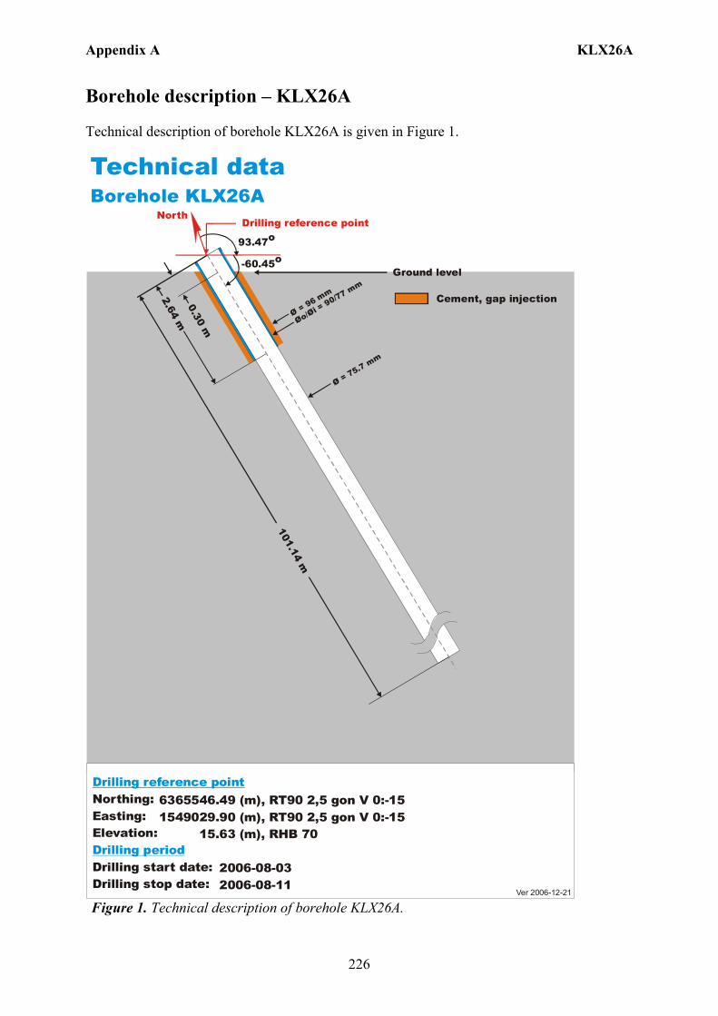
Appendix A KLX26A
226
Borehole description – KLX26A Technical description of borehole KLX26A is given in Figure 1.
6365546.49 (m),1549029.90 (m), 15.63 (m), 2006-08-03 2006-08-11
RT90 2,5 gon V 0:-15 RHB 70
RT90 2,5 gon V 0:-15Northing:Easting:Elevation:
Drilling start date:Drilling stop date:
Drilling reference point
Drilling period
Cement, gap injection
Ver 2006-12-21
Technical dataBorehole KLX26A
North
93.47o
-60.45o
Drilling reference point
Øo/= 90/77 mm
Øi Ø = 96 mm
101.14 m
2.64 m0.30 m
Ø = 75.7 mm
Ground level
Figure 1. Technical description of borehole KLX26A.

Appendix A KLX26A
227
Deviation measurement in KLX26A In total two deviation measurements were conducted in KLX26A. The deviation logging activities are tabulated in Sicada Activity Log, see Table 1. The two Mac/acc measurements (ID 13142397, 13121777) were executed down and up the borehole, with the Flexit instrument. Corrections of measured data were documented in the File References (Sicada) for the measurements. No geomagnetic disturbances exceeding 0.5 degrees were observed on the date of the Mag/acc measurement, see Figure 2. Borehole deviation multiple measurements For the calculation of Borehole deviation multiple measurements (ID 13144294) the two Mag/acc measurements (ID 13142397, 13121777) were used. Table 2 shows all deviation data for the calculation. A subset of the resulting deviation file for every approximately 100 m elevation (from Object_location) is shown in Table 3. The inclination and bearing uncertainties were calculated automatically, and based on these values the “Radius uncertainty” was calculated for every measuring level. Figure 3 shows the resulting deviation data together with the other, not ERROR- marked, deviation activities listed in Table 1.
Figure 2. The geomagnetic field was observed at the Observatory in Uppsala on 2006-09-20.
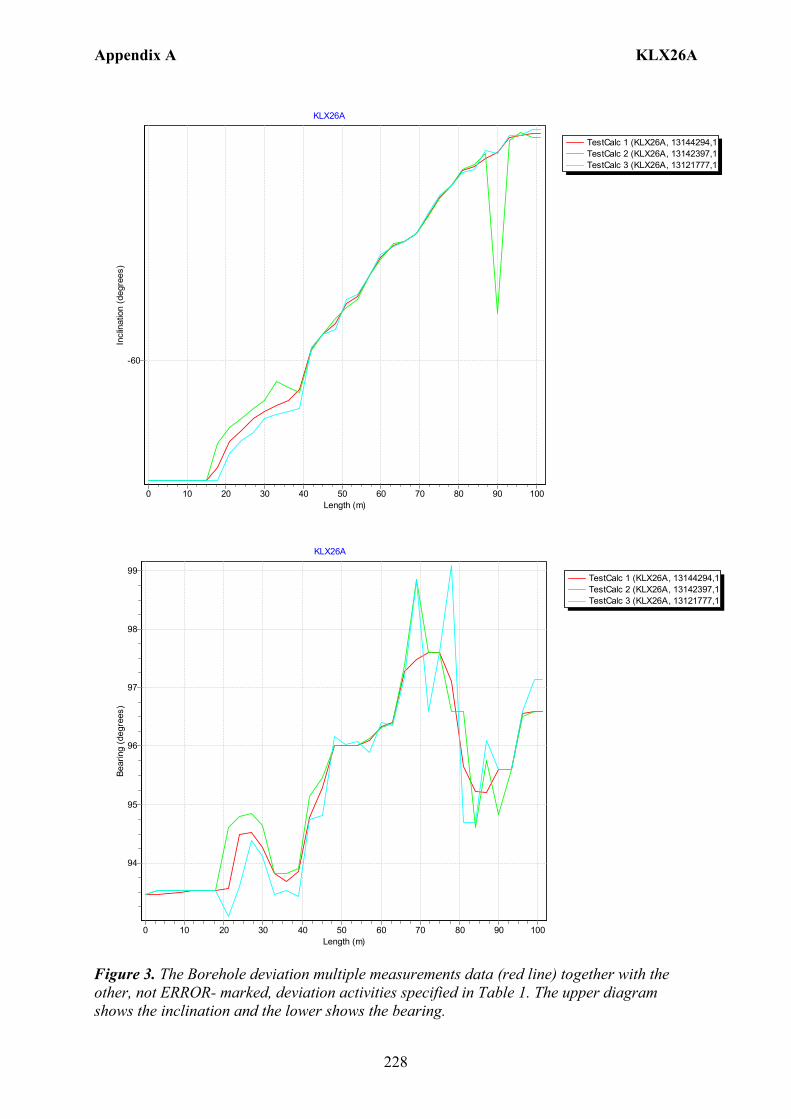
Appendix A KLX26A
228
TestCalc 1 (KLX26A, 13144294,1TestCalc 2 (KLX26A, 13142397,1TestCalc 3 (KLX26A, 13121777,1
KLX26A
Length (m)1009080706050403020100
Incl
inat
ion
(deg
rees
)
-60
TestCalc 1 (KLX26A, 13144294,1TestCalc 2 (KLX26A, 13142397,1TestCalc 3 (KLX26A, 13121777,1
KLX26A
Length (m)1009080706050403020100
Bear
ing
(deg
rees
)
99
98
97
96
95
94
Figure 3. The Borehole deviation multiple measurements data (red line) together with the other, not ERROR- marked, deviation activities specified in Table 1. The upper diagram shows the inclination and the lower shows the bearing.

Appendix A KLX26A
229
Table 1. The deviation logging activities in Sicada.
Idcode Activity Id
Activity Type Code
Activity Start Date Secup(m)
Seclow(m)
Flags
KLX26A 13121777 EG157 Magnetic - accelerometer measurement 2006-09-20 01:49 0.00 99.00 CF KLX26A 13142397 EG157 Magnetic - accelerometer measurement 2006-09-20 02:05 0.00 99.00 CF KLX26A 13144294 EG154 Borehole deviation multiple measurements 2007-01-09 08:00 I C
Table 2. Content of the EG154-file.
Idcode Deviation Activity Id Deviation Angle Type Approved Secup (m)
Approved Seclow (m)
Man Estim Angle Uncert (degrees)
KLX26A 13121777 BEARING 18.00 101.14 KLX26A 13121777 INCLINATION 3.00 101.14 KLX26A 13142397 BEARING 18.00 101.14 KLX26A 13142397 INCLINATION 3.00 101.14
Table 3. Subset (for every approx. 100 m elevation) of the resulting “Object_location” in Sicada.
Idcode
Northing (m)
Easting (m)
Elevation (m)
Length (m)
Elevation_uncert(m)
Inclination (degrees)
Bearing (degrees)
Inclination_uncert(degrees)
Bearing_uncert(degrees)
Radius_uncert (m)
KLX26A 6365546.49 1549029.9 15.63 0 0.00 -60.45 93.47 0.05 0.907 0 KLX26A 6365541.83 1549080.51 -71.8 101.14 0.04 -59.14 96.6 0.05 0.907 0.81
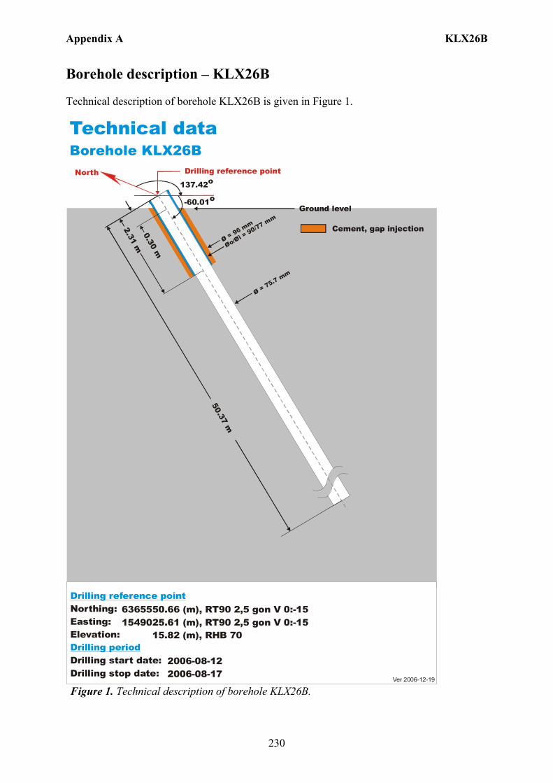
Appendix A KLX26B
230
Borehole description – KLX26B Technical description of borehole KLX26B is given in Figure 1.
6365550.66 (m),1549025.61 (m), 15.82 (m), 2006-08-12 2006-08-17
RT90 2,5 gon V 0:-15 RHB 70
RT90 2,5 gon V 0:-15Northing:Easting:Elevation:
Drilling start date:Drilling stop date:
Drilling reference point
Drilling period
Cement, gap injection
Ver 2006-12-19
Technical dataBorehole KLX26B
North
-60.01o
Drilling reference point
Øo/= 90/77 m
m
Øi Ø = 96 mm
50.37 m
2.31 m0.30 m
Ø = 75.7 mm
Ground level
137.42o
Figure 1. Technical description of borehole KLX26B.

Appendix A KLX26B
231
Deviation measurement in KLX26B In total two deviation measurements were conducted in KLX26B. The deviation logging activities are tabulated in Sicada Activity Log, see Table 1. The two Mac/acc measurements (ID 13143748, 13121778) were executed down and up the borehole, with the Flexit instrument. Corrections of measured data were documented in the File References (Sicada) for the measurements. No geomagnetic disturbances exceeding 0.5 degrees were observed on the date of the Mag/acc measurement, see Figure 2. Borehole deviation multiple measurements For the calculation of Borehole deviation multiple measurements (ID 13144295) the two Mag/acc measurements (ID 13143748, 13121778) were used. Table 2 shows all deviation data for the calculation. A subset of the resulting deviation file for every approximately 100 m elevation (from Object_location) is shown in Table 3. The inclination and bearing uncertainties were calculated automatically, and based on these values the “Radius uncertainty” was calculated for every measuring level. Figure 3 shows the resulting deviation data together with the other, not ERROR- marked, deviation activities listed in Table 1.
Figure 2. The geomagnetic field was observed at the Observatory in Uppsala on 2006-09-20.

Appendix A KLX26B
232
TestCalc 1 (KLX26B, 13144295,1TestCalc 2 (KLX26B, 13143748,1TestCalc 3 (KLX26B, 13121778,1
KLX26B
Length (m)50454035302520151050
Incl
inat
ion
(deg
rees
)-59,25
-59,3
-59,35
-59,4
-59,45
-59,5
-59,55
-59,6
-59,65
-59,7
-59,75
-59,8
-59,85
-59,9
-59,95
-60
-60,05
TestCalc 1 (KLX26B, 13144295,1TestCalc 2 (KLX26B, 13143748,1TestCalc 3 (KLX26B, 13121778,1
KLX26B
Length (m)50454035302520151050
Bear
ing
(deg
rees
)
141
140
139
138
Figure 3. The Borehole deviation multiple measurements data (red line) together with the other, not ERROR- marked, deviation activities specified in Table 1. The upper diagram shows the inclination and the lower shows the bearing.

Appendix A KLX26B
233
Table 1. The deviation logging activities in Sicada.
Idcode Activity Id
Activity Type Code
Activity Start Date Secup(m)
Seclow(m)
Flags
KLX26B 13121778 EG157 Magnetic - accelerometer measurement 2006-09-20 02:23 0.00 48.00 CF KLX26B 13143748 EG157 Magnetic - accelerometer measurement 2006-09-20 02:29 0.00 48.00 CF KLX26B 13144295 EG154 Borehole deviation multiple measurements 2007-01-09 08:00 I C
Table 2. Content of the EG154-file.
Idcode Deviation Activity Id Deviation Angle Type Approved Secup (m)
Approved Seclow (m)
Man Estim Angle Uncert (degrees)
KLX26B 13121778 BEARING 18.00 50.37 KLX26B 13121778 INCLINATION 3.00 50.37 KLX26B 13143748 BEARING 18.00 50.37 KLX26B 13143748 INCLINATION 3.00 50.37
Table 3. Subset (for every approx. 100 m elevation) of the resulting “Object_location” in Sicada.
Idcode
Northing (m)
Easting (m)
Elevation (m)
Length (m)
Elevation_uncert(m)
Inclination (degrees)
Bearing (degrees)
Inclination_uncert(degrees)
Bearing_uncert(degrees)
Radius_uncert (m)
KLX26B 6365550.66 1549025.61 15.82 0 0.00 -60.01 137.42 0.035 0.608 0 KLX26B 6365531.68 1549042.27 -27.76 50.37 0.02 -59.59 139.6 0.035 0.608 0.27
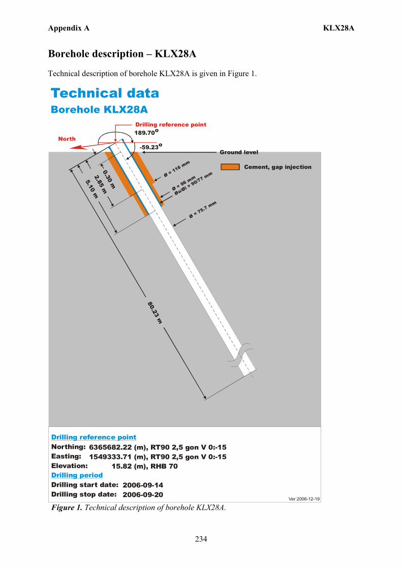
Appendix A KLX28A
234
Borehole description – KLX28A Technical description of borehole KLX28A is given in Figure 1.
6365682.22 (m),1549333.71 (m), 15.82 (m), 2006-09-14 2006-09-20
RT90 2,5 gon V 0:-15 RHB 70
RT90 2,5 gon V 0:-15Northing:Easting:Elevation:
Drilling start date:Drilling stop date:
Drilling reference point
Drilling period
Cement, gap injection
Ver 2006-12-19
Technical dataBorehole KLX28A
North-59.23o
Drilling reference point
Ground level
189.70o
Øo/= 90/77 mm
Øi Ø = 96 mm 5.10 m0.30 m
Ø = 75.7 mm
Ø = 116 mm
2.85 m
Figure 1. Technical description of borehole KLX28A.
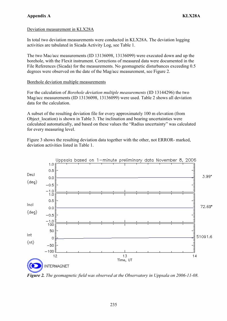
Appendix A KLX28A
235
Deviation measurement in KLX28A In total two deviation measurements were conducted in KLX28A. The deviation logging activities are tabulated in Sicada Activity Log, see Table 1. The two Mac/acc measurements (ID 13136098, 13136099) were executed down and up the borehole, with the Flexit instrument. Corrections of measured data were documented in the File References (Sicada) for the measurements. No geomagnetic disturbances exceeding 0.5 degrees were observed on the date of the Mag/acc measurement, see Figure 2. Borehole deviation multiple measurements For the calculation of Borehole deviation multiple measurements (ID 13144296) the two Mag/acc measurements (ID 13136098, 13136099) were used. Table 2 shows all deviation data for the calculation. A subset of the resulting deviation file for every approximately 100 m elevation (from Object_location) is shown in Table 3. The inclination and bearing uncertainties were calculated automatically, and based on these values the “Radius uncertainty” was calculated for every measuring level. Figure 3 shows the resulting deviation data together with the other, not ERROR- marked, deviation activities listed in Table 1.
Figure 2. The geomagnetic field was observed at the Observatory in Uppsala on 2006-11-08.
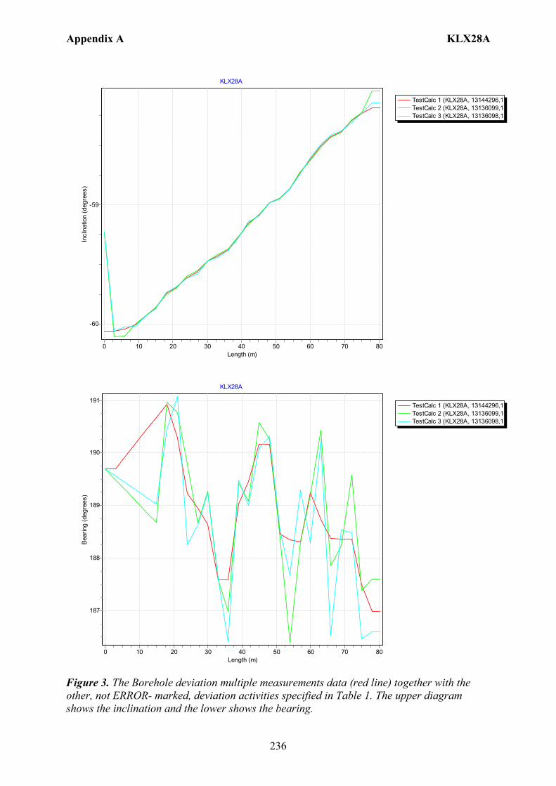
Appendix A KLX28A
236
TestCalc 1 (KLX28A, 13144296,1TestCalc 2 (KLX28A, 13136099,1TestCalc 3 (KLX28A, 13136098,1
KLX28A
Length (m)80706050403020100
Incl
inat
ion
(deg
rees
)
-59
-60
TestCalc 1 (KLX28A, 13144296,1TestCalc 2 (KLX28A, 13136099,1TestCalc 3 (KLX28A, 13136098,1
KLX28A
Length (m)80706050403020100
Bear
ing
(deg
rees
)
191
190
189
188
187
Figure 3. The Borehole deviation multiple measurements data (red line) together with the other, not ERROR- marked, deviation activities specified in Table 1. The upper diagram shows the inclination and the lower shows the bearing.
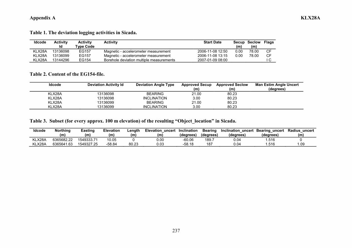
Appendix A KLX28A
237
Table 1. The deviation logging activities in Sicada.
Idcode Activity Id
Activity Type Code
Activity Start Date Secup(m)
Seclow(m)
Flags
KLX28A 13136098 EG157 Magnetic - accelerometer measurement 2006-11-08 12:50 0.00 78.00 CF KLX28A 13136099 EG157 Magnetic - accelerometer measurement 2006-11-08 13:15 0.00 78.00 CF KLX28A 13144296 EG154 Borehole deviation multiple measurements 2007-01-09 08:00 I C
Table 2. Content of the EG154-file.
Idcode Deviation Activity Id Deviation Angle Type Approved Secup (m)
Approved Seclow (m)
Man Estim Angle Uncert (degrees)
KLX28A 13136098 BEARING 21.00 80.23 KLX28A 13136098 INCLINATION 3.00 80.23 KLX28A 13136099 BEARING 21.00 80.23 KLX28A 13136099 INCLINATION 3.00 80.23
Table 3. Subset (for every approx. 100 m elevation) of the resulting “Object_location” in Sicada.
Idcode
Northing (m)
Easting (m)
Elevation (m)
Length (m)
Elevation_uncert(m)
Inclination (degrees)
Bearing (degrees)
Inclination_uncert(degrees)
Bearing_uncert(degrees)
Radius_uncert (m)
KLX28A 6365682.22 1549333.71 10.05 0 0.00 -60.06 189.7 0.04 1.516 0 KLX28A 6365641.63 1549327.25 -58.84 80.23 0.03 -58.18 187 0.04 1.516 1.09
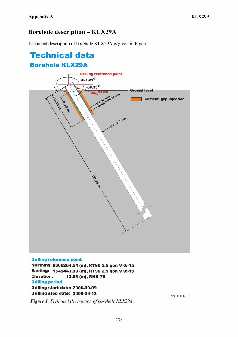
Appendix A KLX29A
238
Borehole description – KLX29A Technical description of borehole KLX29A is given in Figure 1.
6366264.54 (m),1549443.99 (m), 13.63 (m), 2006-09-09 2006-09-13
RT90 2,5 gon V 0:-15 RHB 70
RT90 2,5 gon V 0:-15Northing:Easting:Elevation:
Drilling start date:Drilling stop date:
Drilling reference point
Drilling period
Cement, gap injection
Ver 2006-12-19
Technical dataBorehole KLX29A
North-60.35o
Drilling reference point
Øo/= 90/77 mm
Øi Ø = 96 mm
60.25 m
2.35 m0.30 m
Ø = 75.7 mm
Ground level
321.21o
Figure 1. Technical description of borehole KLX29A.

Appendix A KLX29A
239
Deviation measurement in KLX29A In total two deviation measurements were conducted in KLX29A. The deviation logging activities are tabulated in Sicada Activity Log, see Table 1. The two Mac/acc measurements (ID 13136109, 13136110) were executed down and up the borehole, with the Flexit instrument. Corrections of measured data were documented in the File References (Sicada) for the measurements. No geomagnetic disturbances exceeding 0.5 degrees were observed on the date of the Mag/acc measurement, see Figure 2. Borehole deviation multiple measurements For the calculation of Borehole deviation multiple measurements (ID 13144297) the two Mag/acc measurements (ID 13136109, 13136110) were used. Table 2 shows all deviation data for the calculation. A subset of the resulting deviation file for every approximately 100 m elevation (from Object_location) is shown in Table 3. The inclination and bearing uncertainties were calculated automatically, and based on these values the “Radius uncertainty” was calculated for every measuring level. Figure 3 shows the resulting deviation data together with the other, not ERROR- marked, deviation activities listed in Table 1.
Figure 2. The geomagnetic field was observed at the Observatory in Uppsala on 2006-11-07.
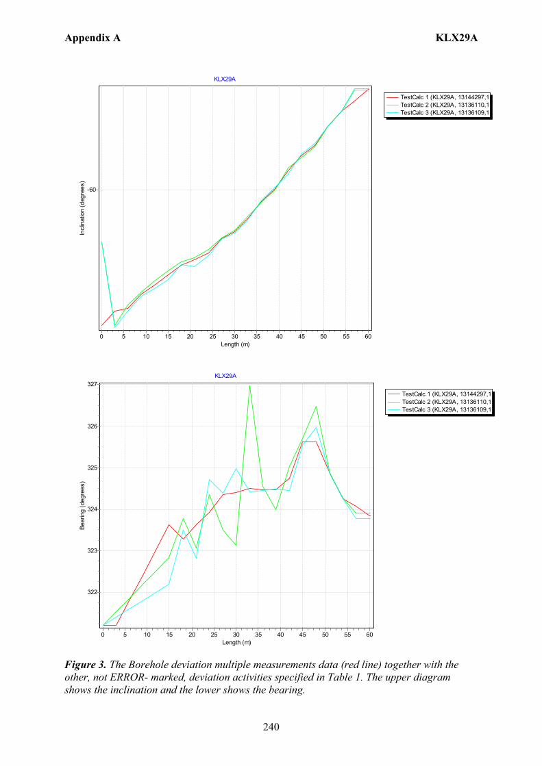
Appendix A KLX29A
240
TestCalc 1 (KLX29A, 13144297,1TestCalc 2 (KLX29A, 13136110,1TestCalc 3 (KLX29A, 13136109,1
KLX29A
Length (m)605550454035302520151050
Incl
inat
ion
(deg
rees
)
-60
TestCalc 1 (KLX29A, 13144297,1TestCalc 2 (KLX29A, 13136110,1TestCalc 3 (KLX29A, 13136109,1
KLX29A
Length (m)605550454035302520151050
Bear
ing
(deg
rees
)
327
326
325
324
323
322
Figure 3. The Borehole deviation multiple measurements data (red line) together with the other, not ERROR- marked, deviation activities specified in Table 1. The upper diagram shows the inclination and the lower shows the bearing.
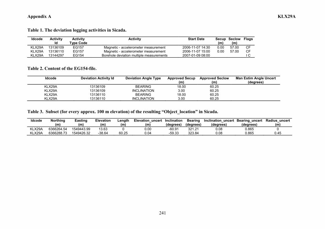
Appendix A KLX29A
241
Table 1. The deviation logging activities in Sicada.
Idcode Activity Id
Activity Type Code
Activity Start Date Secup(m)
Seclow(m)
Flags
KLX29A 13136109 EG157 Magnetic - accelerometer measurement 2006-11-07 14:30 0.00 57.00 CF KLX29A 13136110 EG157 Magnetic - accelerometer measurement 2006-11-07 15:00 0.00 57.00 CF KLX29A 13144297 EG154 Borehole deviation multiple measurements 2007-01-09 08:00 I C
Table 2. Content of the EG154-file.
Idcode Deviation Activity Id Deviation Angle Type Approved Secup (m)
Approved Seclow (m)
Man Estim Angle Uncert (degrees)
KLX29A 13136109 BEARING 18.00 60.25 KLX29A 13136109 INCLINATION 3.00 60.25 KLX29A 13136110 BEARING 18.00 60.25 KLX29A 13136110 INCLINATION 3.00 60.25
Table 3. Subset (for every approx. 100 m elevation) of the resulting “Object_location” in Sicada.
Idcode
Northing (m)
Easting (m)
Elevation (m)
Length (m)
Elevation_uncert(m)
Inclination (degrees)
Bearing (degrees)
Inclination_uncert(degrees)
Bearing_uncert(degrees)
Radius_uncert (m)
KLX29A 6366264.54 1549443.99 13.63 0 0.00 -60.91 321.21 0.08 0.865 0 KLX29A 6366288.73 1549426.32 -38.64 60.25 0.04 -59.33 323.84 0.08 0.865 0.45

Appendix B HLX01
243
Borehole description – HLX01
Technical description of borehole HLX01 is given in Table 1.
Table 1. Technical description of borehole HLX01. Title Value Information about percussion borehole HLX01 (2007-02-05). Comment: No comment exists. BOREHOLE LENGTH: Signed/Approved By Length(m) Reference Level Johan Svensson 100.63 Unknown DRILLING PERIODS: Signed/Approved By From Date To Date Secup(m) Seclow(m) Drilling Type Johan Svensson 1987-10-20 1987-10-21 0.00 100.63 Percussion
drilling STARTING POINT COORDINATE: Signed/Approved By Length(m) Northing(m) Easting(m) Elevation Coord System Johan Svensson 0.00 6367354.49 1549569.77 8.90 RT90-RHB70 STARTING POINT ANGLES: Signed/Approved By Length(m) Bearing Inclination (- = down) Coord System Gerry Johansson 0.00 175.30 -59.40 RT38-RH00 BOREHOLE DIAMETERS: Signed/Approved By Secup(m) Seclow(m) Hole Diam(m) Johan Svensson 0.00 100.00 0.115 CORE DIAMETERS: Signed/Approved By Secup(m) Seclow(m) Core Diam(m) CASING DIAMETERS: Signed/Approved By Secup(m) Seclow(m) Case In(m) Case Out(m) Comment Johan Svensson 0.00 3.00 0.130 0.140 INSTALLED SECTIONS: Signed/Approved By Section No Start Date Secup(m) Seclow(m) Lars Andersson 1 2005-09-23 16.00 100.00 Lars Andersson 2 2005-09-23 0.00 15.00 SECTION INFORMATION: Signed/Approved By Status N/A Packers are expanded. VALVE INFORMATION: Signed/Approved By Status (No valve installation/removal.) End of additional information.
Deviation measurement in HLX01 The only deviation measurement performed in HLX01 was with Boremac, an instrument with a compass and an inclinometer. The deviation logging activity is tabulated in Sicada Activity Log, see Table 2. The Boremac measurement (ID 3013007) was executed down the borehole between the length 0 – 96.00 m, with 1 m separation between the measuring points down to 50 m and then 10 m separation between the measuring points to the bottom of the borehole. Interpolation with 1 m increment was performed in that part and resulted in a new Boremac file (ID 13148082). Corrections of measured data are shown in the File References (Sicada) for the measurements. No geomagnetic data is available for the measuring date, 1987-10-25.

Appendix B HLX01
244
Borehole deviation multiple measurements. In the calculation of Borehole deviation multiple measurements (ID 13148135) the Boremac measurement (ID 13148082) was used. Table 3 shows the deviation data for the calculation. A subset of the resulting deviation file for every approximately 20 m elevation (from Object_location) is shown in Table 4. When only one measurement was executed from 50 m with 10 m separation between the readings an inclination uncertainty of 3.0 and bearing uncertainty of 6.0 is used for calculation of the radius uncertainty for every measuring level. Figure 1 show the resulting deviation data together with the other, not error marked, deviation activities listed in Table 2.
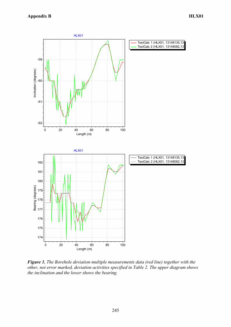
Appendix B HLX01
245
TestCalc 1 (HLX01, 13148135,13TestCalc 2 (HLX01, 13148082,13
HLX01
Length (m)100806040200
Incl
inat
ion
(deg
rees
)
-59
-60
-61
-62
TestCalc 1 (HLX01, 13148135,13TestCalc 2 (HLX01, 13148082,13
HLX01
Length (m)100806040200
Bear
ing
(deg
rees
)
182
181
180
179
178
177
176
175
174
Figure 1. The Borehole deviation multiple measurements data (red line) together with the other, not error marked, deviation activities specified in Table 2. The upper diagram shows the inclination and the lower shows the bearing.
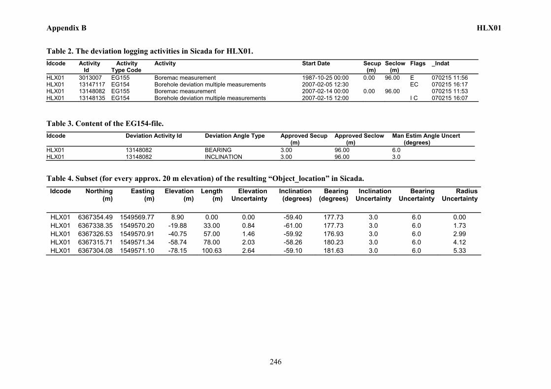
Appendix B HLX01
246
Table 2. The deviation logging activities in Sicada for HLX01. Idcode Activity
Id Activity Type Code
Activity Start Date Secup (m)
Seclow (m)
Flags _Indat
HLX01 3013007 EG155 Boremac measurement 1987-10-25 00:00 0.00 96.00 E 070215 11:56 HLX01 13147117 EG154 Borehole deviation multiple measurements 2007-02-05 12:30 EC 070215 16:17 HLX01 13148082 EG155 Boremac measurement 2007-02-14 00:00 0.00 96.00 070215 11:53 HLX01 13148135 EG154 Borehole deviation multiple measurements 2007-02-15 12:00 I C 070215 16:07
Table 3. Content of the EG154-file. Idcode Deviation Activity Id Deviation Angle Type Approved Secup
(m) Approved Seclow (m)
Man Estim Angle Uncert (degrees)
HLX01 13148082 BEARING 3.00 96.00 6.0 HLX01 13148082 INCLINATION 3.00 96.00 3.0
Table 4. Subset (for every approx. 20 m elevation) of the resulting “Object_location” in Sicada. Idcode Northing
(m) Easting
(m) Elevation
(m)Length
(m)Elevation
UncertaintyInclination (degrees)
Bearing (degrees)
Inclination Uncertainty
Bearing Uncertainty
Radius Uncertainty
HLX01 6367354.49 1549569.77 8.90 0.00 0.00 -59.40 177.73 3.0 6.0 0.00 HLX01 6367338.35 1549570.20 -19.88 33.00 0.84 -61.00 177.73 3.0 6.0 1.73 HLX01 6367326.53 1549570.91 -40.75 57.00 1.46 -59.92 176.93 3.0 6.0 2.99 HLX01 6367315.71 1549571.34 -58.74 78.00 2.03 -58.26 180.23 3.0 6.0 4.12 HLX01 6367304.08 1549571.10 -78.15 100.63 2.64 -59.10 181.63 3.0 6.0 5.33
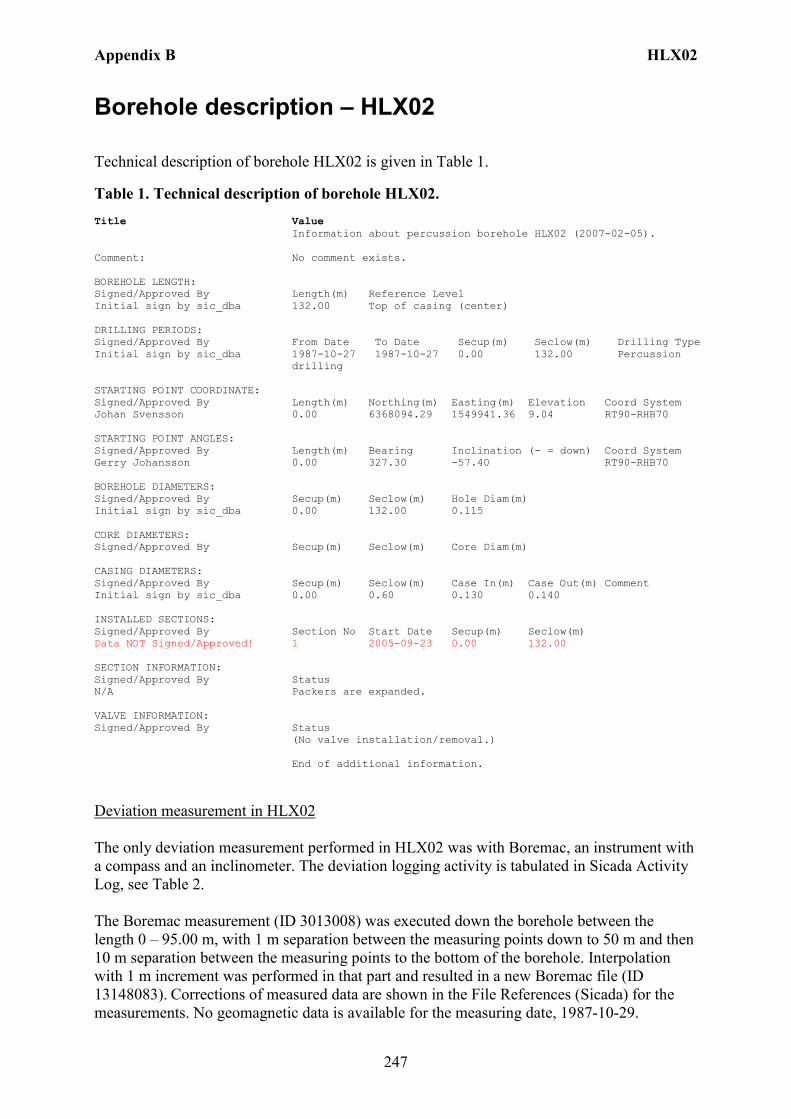
Appendix B HLX02
247
Borehole description – HLX02
Technical description of borehole HLX02 is given in Table 1.
Table 1. Technical description of borehole HLX02. Title Value Information about percussion borehole HLX02 (2007-02-05). Comment: No comment exists. BOREHOLE LENGTH: Signed/Approved By Length(m) Reference Level Initial sign by sic_dba 132.00 Top of casing (center) DRILLING PERIODS: Signed/Approved By From Date To Date Secup(m) Seclow(m) Drilling Type Initial sign by sic_dba 1987-10-27 1987-10-27 0.00 132.00 Percussion
drilling STARTING POINT COORDINATE: Signed/Approved By Length(m) Northing(m) Easting(m) Elevation Coord System Johan Svensson 0.00 6368094.29 1549941.36 9.04 RT90-RHB70 STARTING POINT ANGLES: Signed/Approved By Length(m) Bearing Inclination (- = down) Coord System Gerry Johansson 0.00 327.30 -57.40 RT90-RHB70 BOREHOLE DIAMETERS: Signed/Approved By Secup(m) Seclow(m) Hole Diam(m) Initial sign by sic_dba 0.00 132.00 0.115 CORE DIAMETERS: Signed/Approved By Secup(m) Seclow(m) Core Diam(m) CASING DIAMETERS: Signed/Approved By Secup(m) Seclow(m) Case In(m) Case Out(m) Comment Initial sign by sic_dba 0.00 0.60 0.130 0.140 INSTALLED SECTIONS: Signed/Approved By Section No Start Date Secup(m) Seclow(m) Data NOT Signed/Approved! 1 2005-09-23 0.00 132.00 SECTION INFORMATION: Signed/Approved By Status N/A Packers are expanded. VALVE INFORMATION: Signed/Approved By Status (No valve installation/removal.) End of additional information.
Deviation measurement in HLX02 The only deviation measurement performed in HLX02 was with Boremac, an instrument with a compass and an inclinometer. The deviation logging activity is tabulated in Sicada Activity Log, see Table 2. The Boremac measurement (ID 3013008) was executed down the borehole between the length 0 – 95.00 m, with 1 m separation between the measuring points down to 50 m and then 10 m separation between the measuring points to the bottom of the borehole. Interpolation with 1 m increment was performed in that part and resulted in a new Boremac file (ID 13148083). Corrections of measured data are shown in the File References (Sicada) for the measurements. No geomagnetic data is available for the measuring date, 1987-10-29.

Appendix B HLX02
248
Borehole deviation multiple measurements. In the calculation of Borehole deviation multiple measurements (ID 13148136) the Boremac measurement (ID 13148083) was used. Table 3 shows the deviation data for the calculation. A subset of the resulting deviation file for every approximately 20 m elevation (from Object_location) is shown in Table 4. When only one measurement was executed from 50 m with 10 m separation between the readings an inclination uncertainty of 3.0 and bearing uncertainty of 6.0 is used for calculation of the radius uncertainty for every measuring level. Figure 1 show the resulting deviation data together with the other, not error marked, deviation activities listed in Table 2.
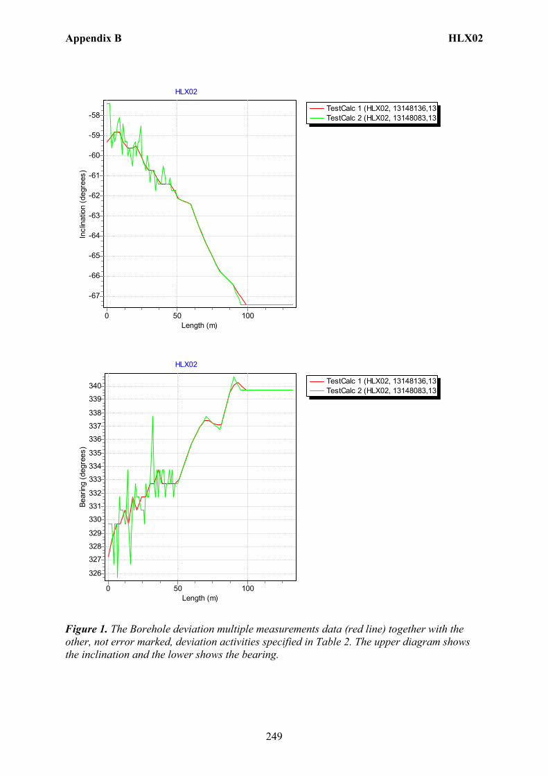
Appendix B HLX02
249
TestCalc 1 (HLX02, 13148136,13TestCalc 2 (HLX02, 13148083,13
HLX02
Length (m)100500
Incl
inat
ion
(deg
rees
)
-58
-59
-60
-61
-62
-63
-64
-65
-66
-67
TestCalc 1 (HLX02, 13148136,13TestCalc 2 (HLX02, 13148083,13
HLX02
Length (m)100500
Bear
ing
(deg
rees
)
340
339
338
337
336
335
334
333
332
331
330
329
328
327
326
Figure 1. The Borehole deviation multiple measurements data (red line) together with the other, not error marked, deviation activities specified in Table 2. The upper diagram shows the inclination and the lower shows the bearing.
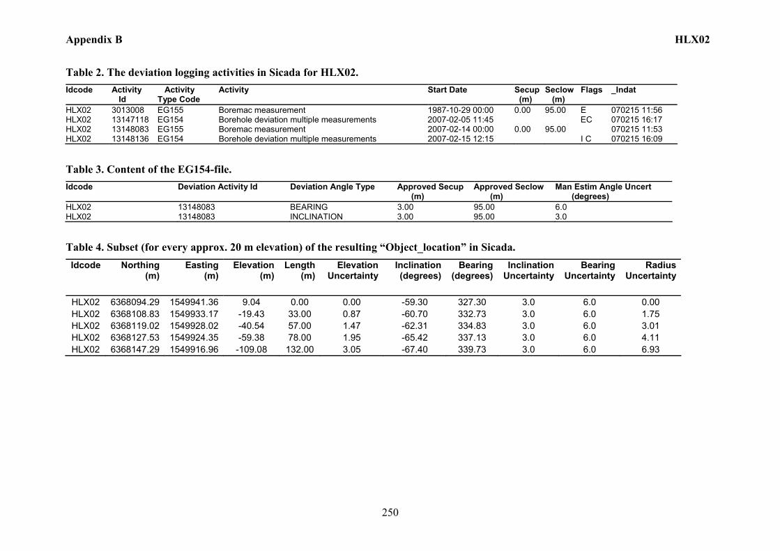
Appendix B HLX02
250
Table 2. The deviation logging activities in Sicada for HLX02. Idcode Activity
Id Activity Type Code
Activity Start Date Secup (m)
Seclow (m)
Flags _Indat
HLX02 3013008 EG155 Boremac measurement 1987-10-29 00:00 0.00 95.00 E 070215 11:56 HLX02 13147118 EG154 Borehole deviation multiple measurements 2007-02-05 11:45 EC 070215 16:17 HLX02 13148083 EG155 Boremac measurement 2007-02-14 00:00 0.00 95.00 070215 11:53 HLX02 13148136 EG154 Borehole deviation multiple measurements 2007-02-15 12:15 I C 070215 16:09
Table 3. Content of the EG154-file. Idcode Deviation Activity Id Deviation Angle Type Approved Secup
(m) Approved Seclow (m)
Man Estim Angle Uncert (degrees)
HLX02 13148083 BEARING 3.00 95.00 6.0 HLX02 13148083 INCLINATION 3.00 95.00 3.0
Table 4. Subset (for every approx. 20 m elevation) of the resulting “Object_location” in Sicada. Idcode Northing
(m) Easting
(m) Elevation
(m)Length
(m)Elevation
UncertaintyInclination (degrees)
Bearing (degrees)
Inclination Uncertainty
Bearing Uncertainty
Radius Uncertainty
HLX02 6368094.29 1549941.36 9.04 0.00 0.00 -59.30 327.30 3.0 6.0 0.00 HLX02 6368108.83 1549933.17 -19.43 33.00 0.87 -60.70 332.73 3.0 6.0 1.75 HLX02 6368119.02 1549928.02 -40.54 57.00 1.47 -62.31 334.83 3.0 6.0 3.01 HLX02 6368127.53 1549924.35 -59.38 78.00 1.95 -65.42 337.13 3.0 6.0 4.11 HLX02 6368147.29 1549916.96 -109.08 132.00 3.05 -67.40 339.73 3.0 6.0 6.93

Appendix B HLX03
251
Borehole description – HLX03
Technical description of borehole HLX03 is given in Table 1.
Table 1. Technical description of borehole HLX03. Title Value Information about percussion borehole HLX03 (2007-02-05). Comment: No comment exists. BOREHOLE LENGTH: Signed/Approved By Length(m) Reference Level Initial sign by sic_dba 100.00 Top of casing (center) DRILLING PERIODS: Signed/Approved By From Date To Date Secup(m) Seclow(m) Drilling Type Initial sign by sic_dba 1987-11-03 1987-11-04 0.00 100.00 Percussion
drilling STARTING POINT COORDINATE: Signed/Approved By Length(m) Northing(m) Easting(m) Elevation Coord System Johan Svensson 0.00 6367820.77 1549921.18 10.45 RT90-RHB70 STARTING POINT ANGLES: Signed/Approved By Length(m) Bearing Inclination (- = down) Coord System Gerry Johansson 0.00 185.30 -62.40 RT90-RHB70 BOREHOLE DIAMETERS: Signed/Approved By Secup(m) Seclow(m) Hole Diam(m) Initial sign by sic_dba 0.00 100.00 0.115 CORE DIAMETERS: Signed/Approved By Secup(m) Seclow(m) Core Diam(m) CASING DIAMETERS: Signed/Approved By Secup(m) Seclow(m) Case In(m) Case Out(m) Comment Initial sign by sic_dba 0.00 1.40 0.130 0.140 INSTALLED SECTIONS: Signed/Approved By Section No Start Date Secup(m) Seclow(m) Initial sign by sic_dba 1 1996-01-10 0.00 100.00 SECTION INFORMATION: Signed/Approved By Status N/A Packers are released. VALVE INFORMATION: Signed/Approved By Status (No valve installation/removal.) End of additional information.
Deviation measurement in HLX03 The only deviation measurement performed in HLX03 was with Boremac, an instrument with a compass and an inclinometer. The deviation logging activity is tabulated in Sicada Activity Log, see Table 2. The Boremac measurement (ID 3013009) was executed down the borehole between the length 0 – 96.00 m, with 1 m separation between the measuring points down to 50 m and then 10 m separation between the measuring points to the bottom of the borehole. Interpolation with 1 m increment was performed in that part and resulted in a new Boremac file (ID 13148084). Corrections of measured data are shown in the File References (Sicada) for the measurements. No geomagnetic data is available for the measuring date, 1987-11-05.

Appendix B HLX03
252
Borehole deviation multiple measurements. In the calculation of Borehole deviation multiple measurements (ID 13148137) the Boremac measurement (ID 13148084) was used. Table 3 shows the deviation data for the calculation. A subset of the resulting deviation file for every approximately 20 m elevation (from Object_location) is shown in Table 4. When only one measurement was executed from 50 m with 10 m separation between the readings an inclination uncertainty of 3.0 and bearing uncertainty of 6.0 is used for calculation of the radius uncertainty for every measuring level. Figure 1 show the resulting deviation data together with the other, not error marked, deviation activities listed in Table 2.
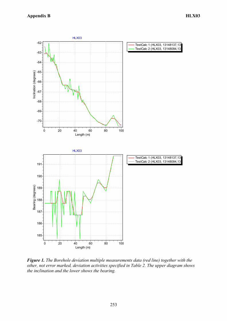
Appendix B HLX03
253
TestCalc 1 (HLX03, 13148137,13TestCalc 2 (HLX03, 13148084,13
HLX03
Length (m)100806040200
Incl
inat
ion
(deg
rees
)
-62
-63
-64
-65
-66
-67
-68
-69
-70
TestCalc 1 (HLX03, 13148137,13TestCalc 2 (HLX03, 13148084,13
HLX03
Length (m)100806040200
Bear
ing
(deg
rees
)
191
190
189
188
187
186
185
Figure 1. The Borehole deviation multiple measurements data (red line) together with the other, not error marked, deviation activities specified in Table 2. The upper diagram shows the inclination and the lower shows the bearing.
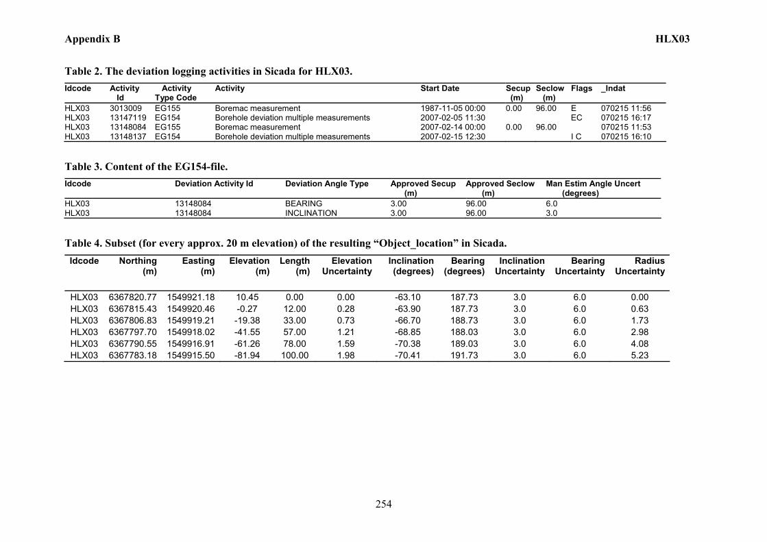
Appendix B HLX03
254
Table 2. The deviation logging activities in Sicada for HLX03. Idcode Activity
Id Activity Type Code
Activity Start Date Secup (m)
Seclow (m)
Flags _Indat
HLX03 3013009 EG155 Boremac measurement 1987-11-05 00:00 0.00 96.00 E 070215 11:56 HLX03 13147119 EG154 Borehole deviation multiple measurements 2007-02-05 11:30 EC 070215 16:17 HLX03 13148084 EG155 Boremac measurement 2007-02-14 00:00 0.00 96.00 070215 11:53 HLX03 13148137 EG154 Borehole deviation multiple measurements 2007-02-15 12:30 I C 070215 16:10
Table 3. Content of the EG154-file. Idcode Deviation Activity Id Deviation Angle Type Approved Secup
(m) Approved Seclow (m)
Man Estim Angle Uncert (degrees)
HLX03 13148084 BEARING 3.00 96.00 6.0 HLX03 13148084 INCLINATION 3.00 96.00 3.0
Table 4. Subset (for every approx. 20 m elevation) of the resulting “Object_location” in Sicada. Idcode Northing
(m) Easting
(m) Elevation
(m)Length
(m)Elevation
UncertaintyInclination (degrees)
Bearing (degrees)
Inclination Uncertainty
Bearing Uncertainty
Radius Uncertainty
HLX03 6367820.77 1549921.18 10.45 0.00 0.00 -63.10 187.73 3.0 6.0 0.00 HLX03 6367815.43 1549920.46 -0.27 12.00 0.28 -63.90 187.73 3.0 6.0 0.63 HLX03 6367806.83 1549919.21 -19.38 33.00 0.73 -66.70 188.73 3.0 6.0 1.73 HLX03 6367797.70 1549918.02 -41.55 57.00 1.21 -68.85 188.03 3.0 6.0 2.98 HLX03 6367790.55 1549916.91 -61.26 78.00 1.59 -70.38 189.03 3.0 6.0 4.08 HLX03 6367783.18 1549915.50 -81.94 100.00 1.98 -70.41 191.73 3.0 6.0 5.23
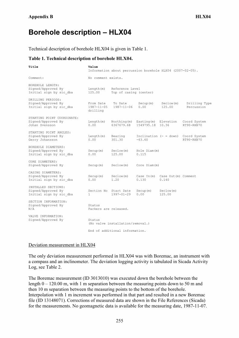
Appendix B HLX04
255
Borehole description – HLX04
Technical description of borehole HLX04 is given in Table 1.
Table 1. Technical description of borehole HLX04. Title Value Information about percussion borehole HLX04 (2007-02-05). Comment: No comment exists. BOREHOLE LENGTH: Signed/Approved By Length(m) Reference Level Initial sign by sic_dba 125.00 Top of casing (center) DRILLING PERIODS: Signed/Approved By From Date To Date Secup(m) Seclow(m) Drilling Type Initial sign by sic_dba 1987-11-05 1987-11-06 0.00 125.00 Percussion
drilling STARTING POINT COORDINATE: Signed/Approved By Length(m) Northing(m) Easting(m) Elevation Coord System Johan Svensson 0.00 6367679.68 1549795.18 10.36 RT90-RHB70 STARTING POINT ANGLES: Signed/Approved By Length(m) Bearing Inclination (- = down) Coord System Gerry Johansson 0.00 301.30 -63.60 RT90-RHB70 BOREHOLE DIAMETERS: Signed/Approved By Secup(m) Seclow(m) Hole Diam(m) Initial sign by sic_dba 0.00 125.00 0.115 CORE DIAMETERS: Signed/Approved By Secup(m) Seclow(m) Core Diam(m) CASING DIAMETERS: Signed/Approved By Secup(m) Seclow(m) Case In(m) Case Out(m) Comment Initial sign by sic_dba 0.00 1.20 0.130 0.140 INSTALLED SECTIONS: Signed/Approved By Section No Start Date Secup(m) Seclow(m) Initial sign by sic_dba 1 1997-01-29 0.00 125.00 SECTION INFORMATION: Signed/Approved By Status N/A Packers are released. VALVE INFORMATION: Signed/Approved By Status (No valve installation/removal.) End of additional information.
Deviation measurement in HLX04 The only deviation measurement performed in HLX04 was with Boremac, an instrument with a compass and an inclinometer. The deviation logging activity is tabulated in Sicada Activity Log, see Table 2. The Boremac measurement (ID 3013010) was executed down the borehole between the length 0 – 120.00 m, with 1 m separation between the measuring points down to 50 m and then 10 m separation between the measuring points to the bottom of the borehole. Interpolation with 1 m increment was performed in that part and resulted in a new Boremac file (ID 13148071). Corrections of measured data are shown in the File References (Sicada) for the measurements. No geomagnetic data is available for the measuring date, 1987-11-07.

Appendix B HLX04
256
Borehole deviation multiple measurements. In the calculation of Borehole deviation multiple measurements (ID 13148139) the Boremac measurement (ID 13148071) was used. Table 3 shows the deviation data for the calculation. A subset of the resulting deviation file for every approximately 20 m elevation (from Object_location) is shown in Table 4. When only one measurement was executed from 50 m with 10 m separation between the readings an inclination uncertainty of 3.0 and bearing uncertainty of 6.0 is used for calculation of the radius uncertainty for every measuring level. Figure 1 show the resulting deviation data together with the other, not error marked, deviation activities listed in Table 2.
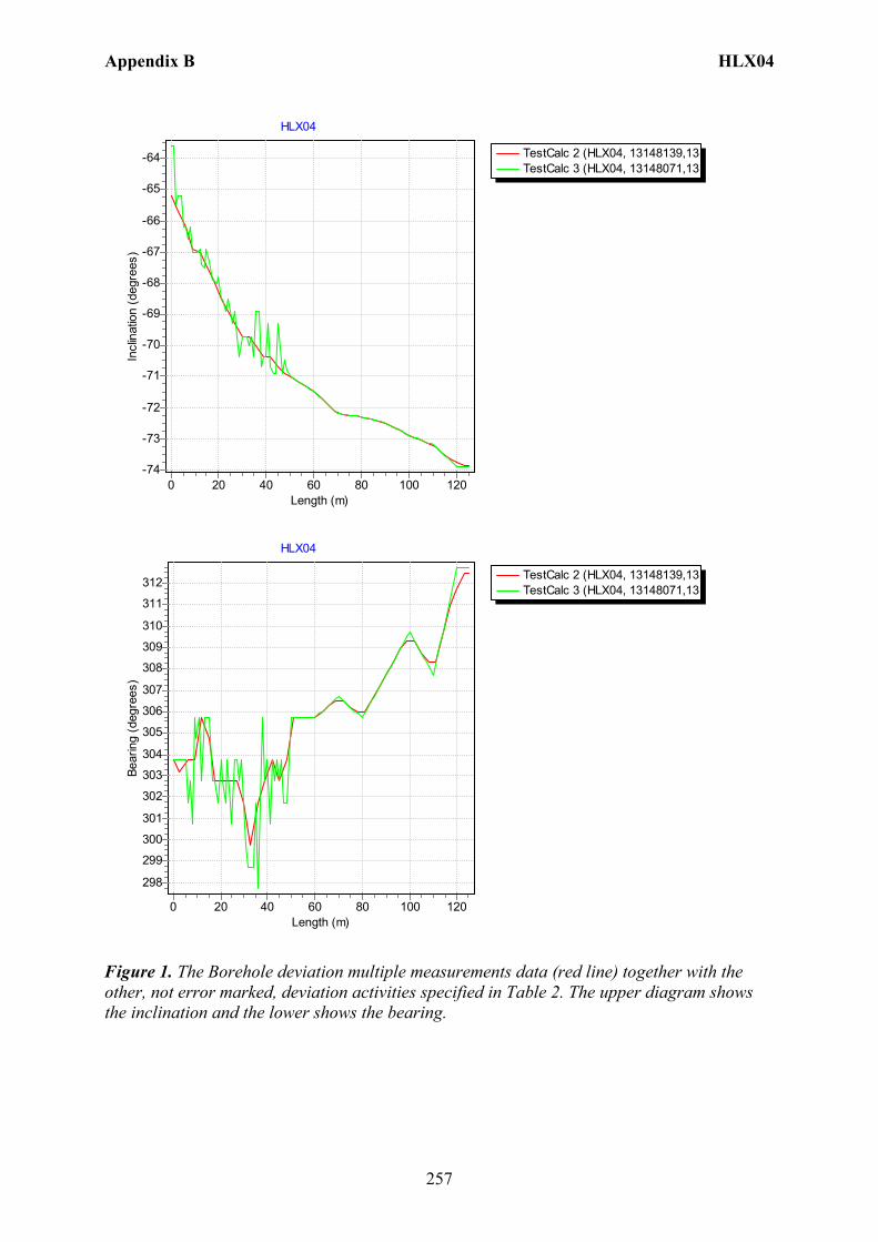
Appendix B HLX04
257
TestCalc 2 (HLX04, 13148139,13TestCalc 3 (HLX04, 13148071,13
HLX04
Length (m)120100806040200
Incl
inat
ion
(deg
rees
)
-64
-65
-66
-67
-68
-69
-70
-71
-72
-73
-74
TestCalc 2 (HLX04, 13148139,13TestCalc 3 (HLX04, 13148071,13
HLX04
Length (m)120100806040200
Bear
ing
(deg
rees
)
312
311
310
309
308
307
306
305
304
303
302
301
300
299
298
Figure 1. The Borehole deviation multiple measurements data (red line) together with the other, not error marked, deviation activities specified in Table 2. The upper diagram shows the inclination and the lower shows the bearing.
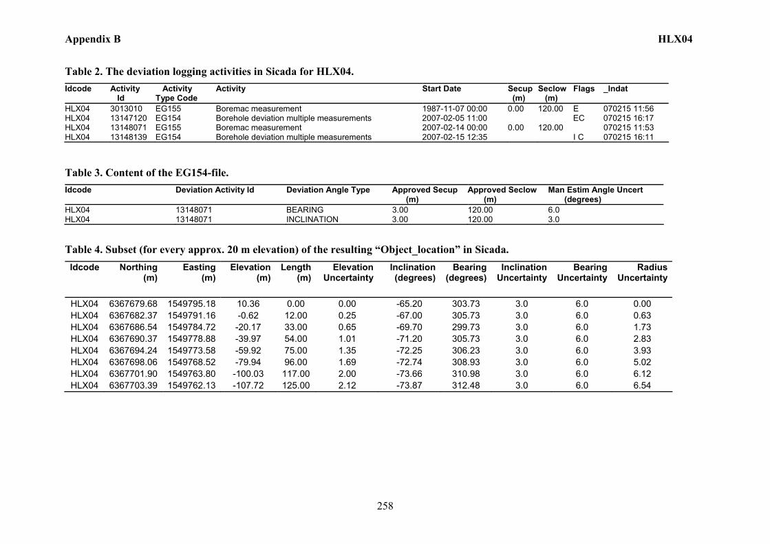
Appendix B HLX04
258
Table 2. The deviation logging activities in Sicada for HLX04. Idcode Activity
Id Activity Type Code
Activity Start Date Secup (m)
Seclow (m)
Flags _Indat
HLX04 3013010 EG155 Boremac measurement 1987-11-07 00:00 0.00 120.00 E 070215 11:56 HLX04 13147120 EG154 Borehole deviation multiple measurements 2007-02-05 11:00 EC 070215 16:17 HLX04 13148071 EG155 Boremac measurement 2007-02-14 00:00 0.00 120.00 070215 11:53 HLX04 13148139 EG154 Borehole deviation multiple measurements 2007-02-15 12:35 I C 070215 16:11
Table 3. Content of the EG154-file. Idcode Deviation Activity Id Deviation Angle Type Approved Secup
(m) Approved Seclow (m)
Man Estim Angle Uncert (degrees)
HLX04 13148071 BEARING 3.00 120.00 6.0 HLX04 13148071 INCLINATION 3.00 120.00 3.0
Table 4. Subset (for every approx. 20 m elevation) of the resulting “Object_location” in Sicada. Idcode Northing
(m) Easting
(m) Elevation
(m)Length
(m)Elevation
UncertaintyInclination (degrees)
Bearing (degrees)
Inclination Uncertainty
Bearing Uncertainty
Radius Uncertainty
HLX04 6367679.68 1549795.18 10.36 0.00 0.00 -65.20 303.73 3.0 6.0 0.00 HLX04 6367682.37 1549791.16 -0.62 12.00 0.25 -67.00 305.73 3.0 6.0 0.63 HLX04 6367686.54 1549784.72 -20.17 33.00 0.65 -69.70 299.73 3.0 6.0 1.73 HLX04 6367690.37 1549778.88 -39.97 54.00 1.01 -71.20 305.73 3.0 6.0 2.83 HLX04 6367694.24 1549773.58 -59.92 75.00 1.35 -72.25 306.23 3.0 6.0 3.93 HLX04 6367698.06 1549768.52 -79.94 96.00 1.69 -72.74 308.93 3.0 6.0 5.02 HLX04 6367701.90 1549763.80 -100.03 117.00 2.00 -73.66 310.98 3.0 6.0 6.12 HLX04 6367703.39 1549762.13 -107.72 125.00 2.12 -73.87 312.48 3.0 6.0 6.54

Appendix B HLX05
259
Borehole description – HLX05
Technical description of borehole HLX05 is given in Table 1.
Table 1. Technical description of borehole HLX05. Title Value Information about percussion borehole HLX05 (2007-02-05). Comment: No comment exists. BOREHOLE LENGTH: Signed/Approved By Length(m) Reference Level Initial sign by sic_dba 100.00 Top of casing (center) DRILLING PERIODS: Signed/Approved By From Date To Date Secup(m) Seclow(m) Drilling Type Initial sign by sic_dba 1987-11-04 1987-11-05 0.00 100.00 Percussion
drilling STARTING POINT COORDINATE: Signed/Approved By Length(m) Northing(m) Easting(m) Elevation Coord System Johan Svensson 0.00 6367558.31 1549968.58 15.71 RT90-RHB70 STARTING POINT ANGLES: Signed/Approved By Length(m) Bearing Inclination (- = down) Coord System Gerry Johansson 0.00 175.30 -57.70 RT38-RH00 BOREHOLE DIAMETERS: Signed/Approved By Secup(m) Seclow(m) Hole Diam(m) Initial sign by sic_dba 0.00 100.00 0.115 CORE DIAMETERS: Signed/Approved By Secup(m) Seclow(m) Core Diam(m) CASING DIAMETERS: Signed/Approved By Secup(m) Seclow(m) Case In(m) Case Out(m) Comment Initial sign by sic_dba 0.00 0.60 0.130 0.140 INSTALLED SECTIONS: Signed/Approved By Section No Start Date Secup(m) Seclow(m) Initial sign by sic_dba 1 1997-01-29 0.00 100.00 SECTION INFORMATION: Signed/Approved By Status N/A Packers are released. VALVE INFORMATION: Signed/Approved By Status (No valve installation/removal.) End of additional information.
Deviation measurement in HLX05 The only deviation measurement performed in HLX05 was with Boremac, an instrument with a compass and an inclinometer. The deviation logging activity is tabulated in Sicada Activity Log, see Table 2. The Boremac measurement (ID 3013011) was executed down the borehole between the length 0 – 99.00 m, with 1 m separation between the measuring points down to 50 m and then 10 m separation between the measuring points to the bottom of the borehole. Interpolation with 1 m increment was performed in that part and resulted in a new Boremac file (ID 13148073). Corrections of measured data are shown in the File References (Sicada) for the measurements. No geomagnetic data is available for the measuring date, 1987-11-06.

Appendix B HLX05
260
Borehole deviation multiple measurements. In the calculation of Borehole deviation multiple measurements (ID 13148140) the Boremac measurement (ID 13148073) was used. Table 3 shows the deviation data for the calculation. A subset of the resulting deviation file for every approximately 20 m elevation (from Object_location) is shown in Table 4. When only one measurement was executed from 50 m with 10 m separation between the readings an inclination uncertainty of 3.0 and bearing uncertainty of 6.0 is used for calculation of the radius uncertainty for every measuring level. Figure 1 show the resulting deviation data together with the other, not error marked, deviation activities listed in Table 2.
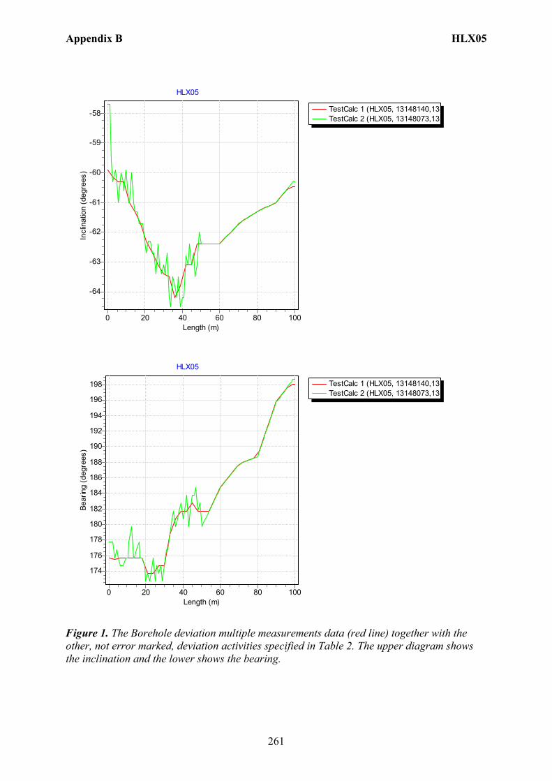
Appendix B HLX05
261
TestCalc 1 (HLX05, 13148140,13TestCalc 2 (HLX05, 13148073,13
HLX05
Length (m)100806040200
Incl
inat
ion
(deg
rees
)
-58
-59
-60
-61
-62
-63
-64
TestCalc 1 (HLX05, 13148140,13TestCalc 2 (HLX05, 13148073,13
HLX05
Length (m)100806040200
Bear
ing
(deg
rees
)
198
196
194
192
190
188
186
184
182
180
178
176
174
Figure 1. The Borehole deviation multiple measurements data (red line) together with the other, not error marked, deviation activities specified in Table 2. The upper diagram shows the inclination and the lower shows the bearing.
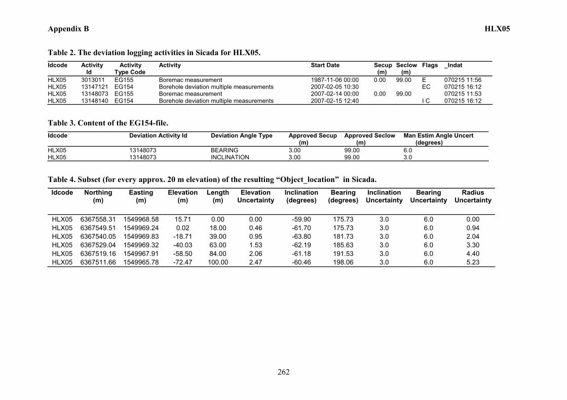
Appendix B HLX05
262
Table 2. The deviation logging activities in Sicada for HLX05. Idcode Activity
Id Activity Type Code
Activity Start Date Secup (m)
Seclow (m)
Flags _Indat
HLX05 3013011 EG155 Boremac measurement 1987-11-06 00:00 0.00 99.00 E 070215 11:56 HLX05 13147121 EG154 Borehole deviation multiple measurements 2007-02-05 10:30 EC 070215 16:12 HLX05 13148073 EG155 Boremac measurement 2007-02-14 00:00 0.00 99.00 070215 11:53 HLX05 13148140 EG154 Borehole deviation multiple measurements 2007-02-15 12:40 I C 070215 16:12
Table 3. Content of the EG154-file. Idcode Deviation Activity Id Deviation Angle Type Approved Secup
(m) Approved Seclow (m)
Man Estim Angle Uncert (degrees)
HLX05 13148073 BEARING 3.00 99.00 6.0 HLX05 13148073 INCLINATION 3.00 99.00 3.0
Table 4. Subset (for every approx. 20 m elevation) of the resulting “Object_location” in Sicada. Idcode Northing
(m) Easting
(m) Elevation
(m) Length
(m) Elevation
Uncertainty Inclination (degrees)
Bearing (degrees)
Inclination Uncertainty
Bearing Uncertainty
Radius Uncertainty
HLX05 6367558.31 1549968.58 15.71 0.00 0.00 -59.90 175.73 3.0 6.0 0.00 HLX05 6367549.51 1549969.24 0.02 18.00 0.46 -61.70 175.73 3.0 6.0 0.94 HLX05 6367540.05 1549969.83 -18.71 39.00 0.95 -63.80 181.73 3.0 6.0 2.04 HLX05 6367529.04 1549969.32 -40.03 63.00 1.53 -62.19 185.63 3.0 6.0 3.30 HLX05 6367519.16 1549967.91 -58.50 84.00 2.06 -61.18 191.53 3.0 6.0 4.40 HLX05 6367511.66 1549965.78 -72.47 100.00 2.47 -60.46 198.06 3.0 6.0 5.23
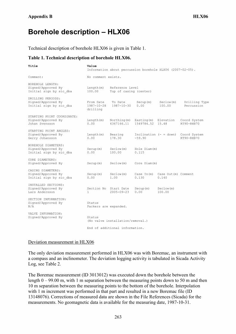
Appendix B HLX06
263
Borehole description – HLX06
Technical description of borehole HLX06 is given in Table 1.
Table 1. Technical description of borehole HLX06. Title Value Information about percussion borehole HLX06 (2007-02-05). Comment: No comment exists. BOREHOLE LENGTH: Signed/Approved By Length(m) Reference Level Initial sign by sic_dba 100.00 Top of casing (center) DRILLING PERIODS: Signed/Approved By From Date To Date Secup(m) Seclow(m) Drilling Type Initial sign by sic_dba 1987-10-28 1987-10-30 0.00 100.00 Percussion
drilling STARTING POINT COORDINATE: Signed/Approved By Length(m) Northing(m) Easting(m) Elevation Coord System Johan Svensson 0.00 6367166.11 1549784.52 15.48 RT90-RHB70 STARTING POINT ANGLES: Signed/Approved By Length(m) Bearing Inclination (- = down) Coord System Gerry Johansson 0.00 178.30 -59.90 RT90-RHB70 BOREHOLE DIAMETERS: Signed/Approved By Secup(m) Seclow(m) Hole Diam(m) Initial sign by sic_dba 0.00 100.00 0.115 CORE DIAMETERS: Signed/Approved By Secup(m) Seclow(m) Core Diam(m) CASING DIAMETERS: Signed/Approved By Secup(m) Seclow(m) Case In(m) Case Out(m) Comment Initial sign by sic_dba 0.00 1.00 0.130 0.140 INSTALLED SECTIONS: Signed/Approved By Section No Start Date Secup(m) Seclow(m) Lars Andersson 1 2005-09-23 0.00 100.00 SECTION INFORMATION: Signed/Approved By Status N/A Packers are expanded. VALVE INFORMATION: Signed/Approved By Status (No valve installation/removal.) End of additional information.
Deviation measurement in HLX06 The only deviation measurement performed in HLX06 was with Boremac, an instrument with a compass and an inclinometer. The deviation logging activity is tabulated in Sicada Activity Log, see Table 2. The Boremac measurement (ID 3013012) was executed down the borehole between the length 0 – 99.00 m, with 1 m separation between the measuring points down to 50 m and then 10 m separation between the measuring points to the bottom of the borehole. Interpolation with 1 m increment was performed in that part and resulted in a new Boremac file (ID 13148076). Corrections of measured data are shown in the File References (Sicada) for the measurements. No geomagnetic data is available for the measuring date, 1987-10-31.

Appendix B HLX06
264
Borehole deviation multiple measurements. In the calculation of Borehole deviation multiple measurements (ID 13148141) the Boremac measurement (ID 13148076) was used. Table 3 shows the deviation data for the calculation. A subset of the resulting deviation file for every approximately 20 m elevation (from Object_location) is shown in Table 4. When only one measurement was executed from 50 m with 10 m separation between the readings an inclination uncertainty of 3.0 and bearing uncertainty of 6.0 is used for calculation of the radius uncertainty for every measuring level. Figure 1 show the resulting deviation data together with the other, not error marked, deviation activities listed in Table 2.
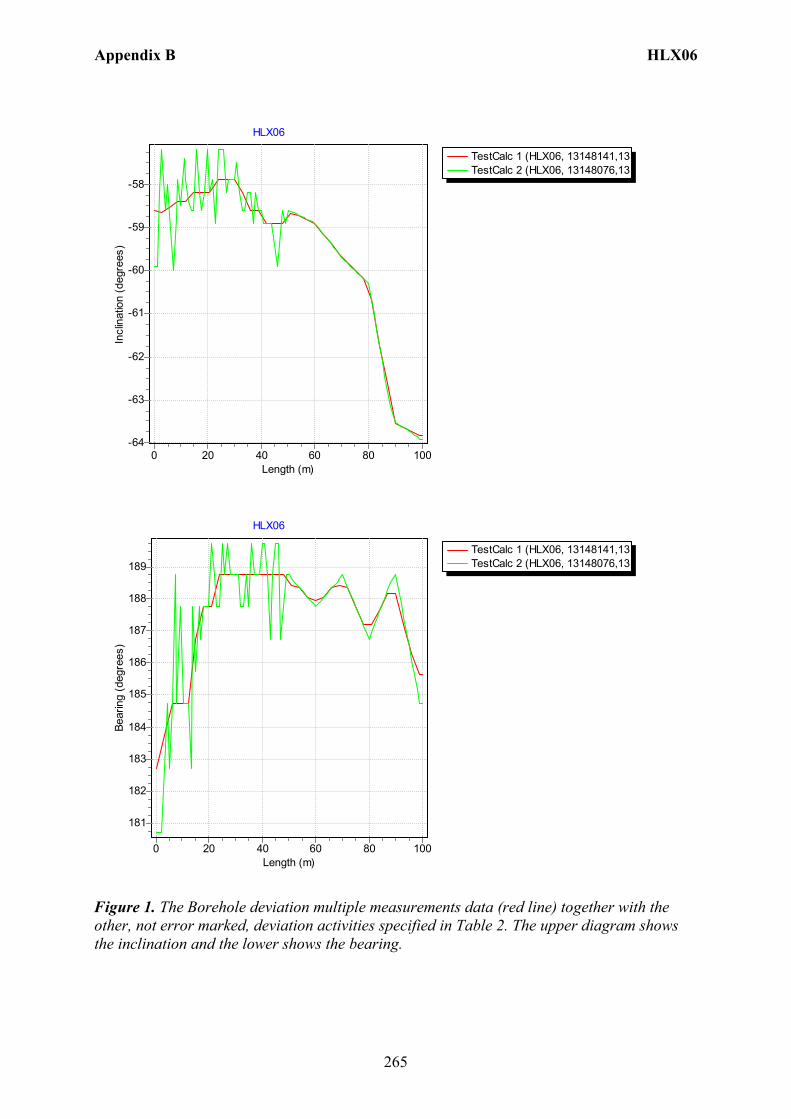
Appendix B HLX06
265
TestCalc 1 (HLX06, 13148141,13TestCalc 2 (HLX06, 13148076,13
HLX06
Length (m)100806040200
Incl
inat
ion
(deg
rees
)
-58
-59
-60
-61
-62
-63
-64
TestCalc 1 (HLX06, 13148141,13TestCalc 2 (HLX06, 13148076,13
HLX06
Length (m)100806040200
Bear
ing
(deg
rees
)
189
188
187
186
185
184
183
182
181
Figure 1. The Borehole deviation multiple measurements data (red line) together with the other, not error marked, deviation activities specified in Table 2. The upper diagram shows the inclination and the lower shows the bearing.

Appendix B HLX06
266
Table 2. The deviation logging activities in Sicada for HLX06. Idcode Activity
Id Activity Type Code
Activity Start Date Secup (m)
Seclow (m)
Flags _Indat
HLX06 3013012 EG155 Boremac measurement 1987-10-31 00:00 0.00 99.00 E 070215 11:56 HLX06 13147122 EG154 Borehole deviation multiple measurements 2007-02-05 10:00 EC 070215 16:17 HLX06 13148076 EG155 Boremac measurement 2007-02-14 00:00 0.00 99.00 070215 11:53 HLX06 13148141 EG154 Borehole deviation multiple measurements 2007-02-15 12:40 I C 070215 16:13
Table 3. Content of the EG154-file. Idcode Deviation Activity Id Deviation Angle Type Approved Secup
(m) Approved Seclow (m)
Man Estim Angle Uncert (degrees)
HLX06 13148076 BEARING 3.00 99.00 6.0 HLX06 13148076 INCLINATION 3.00 99.00 3.0
Table 4. Subset (for every approx. 20 m elevation) of the resulting “Object_location” in Sicada. Idcode Northing
(m) Easting
(m) Elevation
(m) Length
(m) Elevation
Uncertainty Inclination (degrees)
Bearing (degrees)
Inclination Uncertainty
Bearing Uncertainty
Radius Uncertainty
HLX06 6367166.11 1549784.52 15.48 0.00 0.00 -58.60 182.73 3.0 6.0 0.00 HLX06 6367156.72 1549783.71 0.14 18.00 0.49 -58.20 187.73 3.0 6.0 0.99 HLX06 6367144.22 1549781.83 -20.26 42.00 1.15 -58.90 188.73 3.0 6.0 2.31 HLX06 6367131.96 1549780.03 -40.81 66.00 1.80 -59.38 188.33 3.0 6.0 3.60 HLX06 6367121.69 1549778.62 -59.07 87.00 2.34 -62.61 188.17 3.0 6.0 4.70 HLX06 6367115.95 1549777.91 -70.71 100.00 2.64 -63.81 185.62 3.0 6.0 5.38
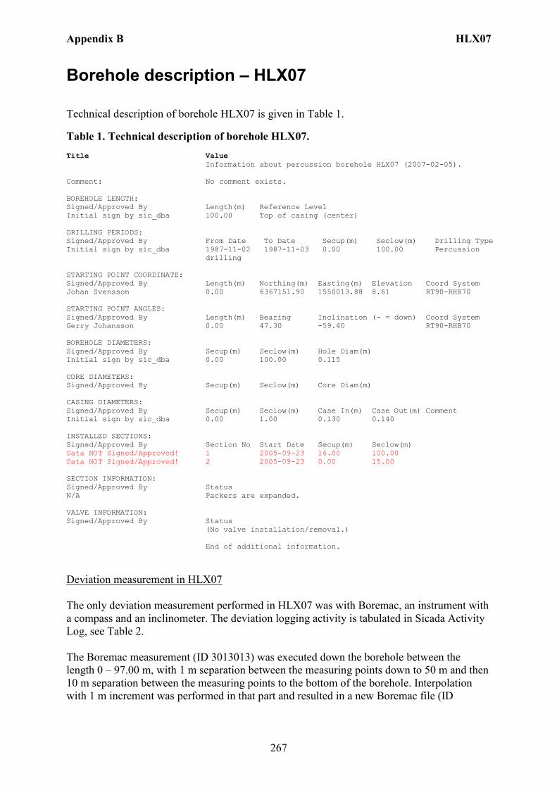
Appendix B HLX07
267
Borehole description – HLX07
Technical description of borehole HLX07 is given in Table 1.
Table 1. Technical description of borehole HLX07. Title Value Information about percussion borehole HLX07 (2007-02-05). Comment: No comment exists. BOREHOLE LENGTH: Signed/Approved By Length(m) Reference Level Initial sign by sic_dba 100.00 Top of casing (center) DRILLING PERIODS: Signed/Approved By From Date To Date Secup(m) Seclow(m) Drilling Type Initial sign by sic_dba 1987-11-02 1987-11-03 0.00 100.00 Percussion
drilling STARTING POINT COORDINATE: Signed/Approved By Length(m) Northing(m) Easting(m) Elevation Coord System Johan Svensson 0.00 6367151.90 1550013.88 8.61 RT90-RHB70 STARTING POINT ANGLES: Signed/Approved By Length(m) Bearing Inclination (- = down) Coord System Gerry Johansson 0.00 47.30 -59.40 RT90-RHB70 BOREHOLE DIAMETERS: Signed/Approved By Secup(m) Seclow(m) Hole Diam(m) Initial sign by sic_dba 0.00 100.00 0.115 CORE DIAMETERS: Signed/Approved By Secup(m) Seclow(m) Core Diam(m) CASING DIAMETERS: Signed/Approved By Secup(m) Seclow(m) Case In(m) Case Out(m) Comment Initial sign by sic_dba 0.00 1.00 0.130 0.140 INSTALLED SECTIONS: Signed/Approved By Section No Start Date Secup(m) Seclow(m) Data NOT Signed/Approved! 1 2005-09-23 16.00 100.00 Data NOT Signed/Approved! 2 2005-09-23 0.00 15.00 SECTION INFORMATION: Signed/Approved By Status N/A Packers are expanded. VALVE INFORMATION: Signed/Approved By Status (No valve installation/removal.) End of additional information.
Deviation measurement in HLX07 The only deviation measurement performed in HLX07 was with Boremac, an instrument with a compass and an inclinometer. The deviation logging activity is tabulated in Sicada Activity Log, see Table 2. The Boremac measurement (ID 3013013) was executed down the borehole between the length 0 – 97.00 m, with 1 m separation between the measuring points down to 50 m and then 10 m separation between the measuring points to the bottom of the borehole. Interpolation with 1 m increment was performed in that part and resulted in a new Boremac file (ID

Appendix B HLX07
268
13148075). Corrections of measured data are shown in the File References (Sicada) for the measurements. No geomagnetic data is available for the measuring date, 1987-11-04. Borehole deviation multiple measurements. In the calculation of Borehole deviation multiple measurements (ID 13148142) the Boremac measurement (ID 13148075) was used. Table 3 shows the deviation data for the calculation. A subset of the resulting deviation file for every approximately 20 m elevation (from Object_location) is shown in Table 4. When only one measurement was executed from 50 m with 10 m separation between the readings an inclination uncertainty of 3.0 and bearing uncertainty of 6.0 is used for calculation of the radius uncertainty for every measuring level. Figure 1 show the resulting deviation data together with the other, not error marked, deviation activities listed in Table 2.
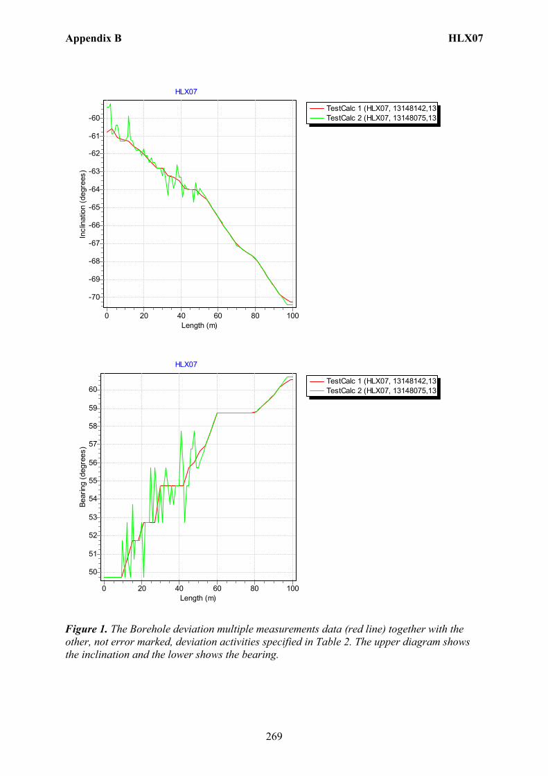
Appendix B HLX07
269
TestCalc 1 (HLX07, 13148142,13TestCalc 2 (HLX07, 13148075,13
HLX07
Length (m)100806040200
Incl
inat
ion
(deg
rees
)
-60
-61
-62
-63
-64
-65
-66
-67
-68
-69
-70
TestCalc 1 (HLX07, 13148142,13TestCalc 2 (HLX07, 13148075,13
HLX07
Length (m)100806040200
Bear
ing
(deg
rees
)
60
59
58
57
56
55
54
53
52
51
50
Figure 1. The Borehole deviation multiple measurements data (red line) together with the other, not error marked, deviation activities specified in Table 2. The upper diagram shows the inclination and the lower shows the bearing.
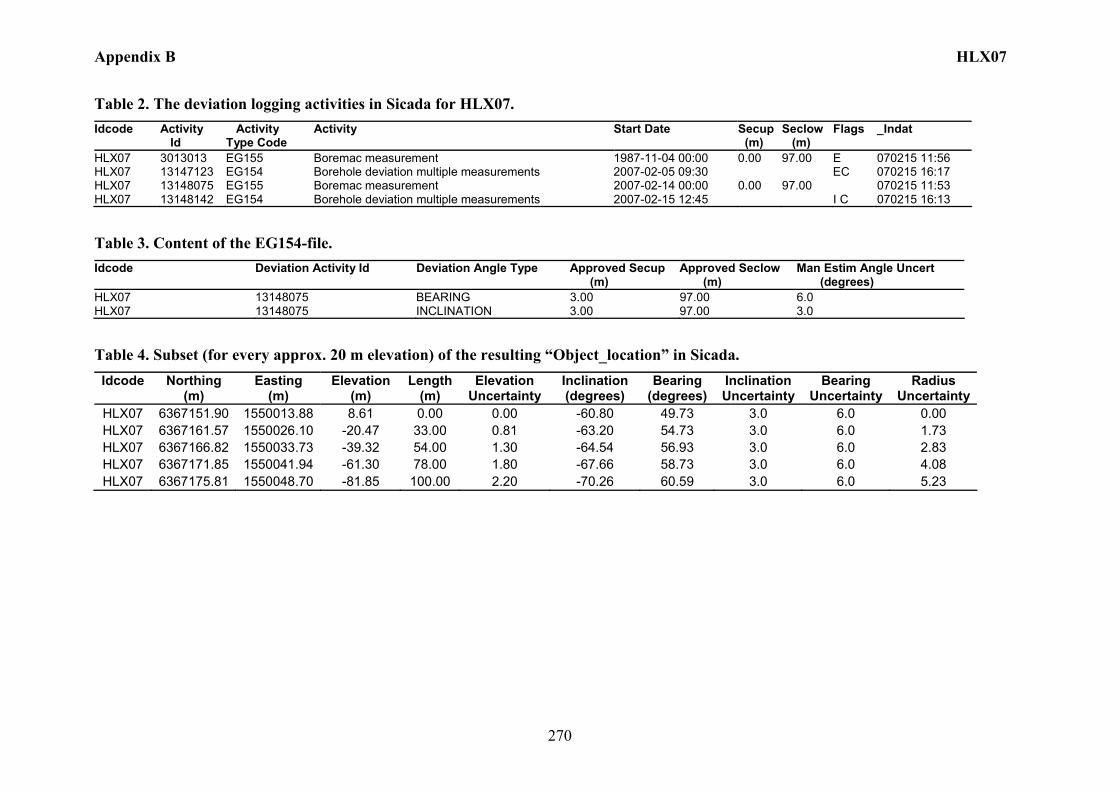
Appendix B HLX07
270
Table 2. The deviation logging activities in Sicada for HLX07. Idcode Activity
Id Activity Type Code
Activity Start Date Secup (m)
Seclow (m)
Flags _Indat
HLX07 3013013 EG155 Boremac measurement 1987-11-04 00:00 0.00 97.00 E 070215 11:56 HLX07 13147123 EG154 Borehole deviation multiple measurements 2007-02-05 09:30 EC 070215 16:17 HLX07 13148075 EG155 Boremac measurement 2007-02-14 00:00 0.00 97.00 070215 11:53 HLX07 13148142 EG154 Borehole deviation multiple measurements 2007-02-15 12:45 I C 070215 16:13
Table 3. Content of the EG154-file. Idcode Deviation Activity Id Deviation Angle Type Approved Secup
(m) Approved Seclow (m)
Man Estim Angle Uncert (degrees)
HLX07 13148075 BEARING 3.00 97.00 6.0 HLX07 13148075 INCLINATION 3.00 97.00 3.0
Table 4. Subset (for every approx. 20 m elevation) of the resulting “Object_location” in Sicada. Idcode Northing
(m) Easting
(m) Elevation
(m) Length
(m) Elevation
Uncertainty Inclination (degrees)
Bearing (degrees)
Inclination Uncertainty
Bearing Uncertainty
Radius Uncertainty
HLX07 6367151.90 1550013.88 8.61 0.00 0.00 -60.80 49.73 3.0 6.0 0.00 HLX07 6367161.57 1550026.10 -20.47 33.00 0.81 -63.20 54.73 3.0 6.0 1.73 HLX07 6367166.82 1550033.73 -39.32 54.00 1.30 -64.54 56.93 3.0 6.0 2.83 HLX07 6367171.85 1550041.94 -61.30 78.00 1.80 -67.66 58.73 3.0 6.0 4.08 HLX07 6367175.81 1550048.70 -81.85 100.00 2.20 -70.26 60.59 3.0 6.0 5.23
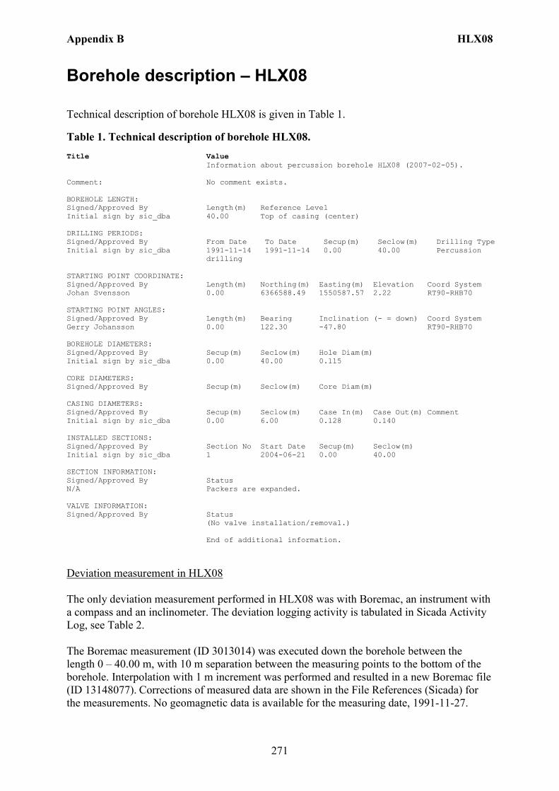
Appendix B HLX08
271
Borehole description – HLX08
Technical description of borehole HLX08 is given in Table 1.
Table 1. Technical description of borehole HLX08. Title Value Information about percussion borehole HLX08 (2007-02-05). Comment: No comment exists. BOREHOLE LENGTH: Signed/Approved By Length(m) Reference Level Initial sign by sic_dba 40.00 Top of casing (center) DRILLING PERIODS: Signed/Approved By From Date To Date Secup(m) Seclow(m) Drilling Type Initial sign by sic_dba 1991-11-14 1991-11-14 0.00 40.00 Percussion
drilling STARTING POINT COORDINATE: Signed/Approved By Length(m) Northing(m) Easting(m) Elevation Coord System Johan Svensson 0.00 6366588.49 1550587.57 2.22 RT90-RHB70 STARTING POINT ANGLES: Signed/Approved By Length(m) Bearing Inclination (- = down) Coord System Gerry Johansson 0.00 122.30 -47.80 RT90-RHB70 BOREHOLE DIAMETERS: Signed/Approved By Secup(m) Seclow(m) Hole Diam(m) Initial sign by sic_dba 0.00 40.00 0.115 CORE DIAMETERS: Signed/Approved By Secup(m) Seclow(m) Core Diam(m) CASING DIAMETERS: Signed/Approved By Secup(m) Seclow(m) Case In(m) Case Out(m) Comment Initial sign by sic_dba 0.00 6.00 0.128 0.140 INSTALLED SECTIONS: Signed/Approved By Section No Start Date Secup(m) Seclow(m) Initial sign by sic_dba 1 2004-06-21 0.00 40.00 SECTION INFORMATION: Signed/Approved By Status N/A Packers are expanded. VALVE INFORMATION: Signed/Approved By Status (No valve installation/removal.) End of additional information.
Deviation measurement in HLX08 The only deviation measurement performed in HLX08 was with Boremac, an instrument with a compass and an inclinometer. The deviation logging activity is tabulated in Sicada Activity Log, see Table 2. The Boremac measurement (ID 3013014) was executed down the borehole between the length 0 – 40.00 m, with 10 m separation between the measuring points to the bottom of the borehole. Interpolation with 1 m increment was performed and resulted in a new Boremac file (ID 13148077). Corrections of measured data are shown in the File References (Sicada) for the measurements. No geomagnetic data is available for the measuring date, 1991-11-27.
Appendix B HLX08
272
Borehole deviation multiple measurements. In the calculation of Borehole deviation multiple measurements (ID 13148143) the Boremac measurement (ID 13148077) was used. Table 3 shows the deviation data for the calculation. A subset of the resulting deviation file for every approximately 20 m elevation (from Object_location) is shown in Table 4. When only one measurement was executed with 10 m separation between the readings an inclination uncertainty of 3.0 and bearing uncertainty of 6.0 is used for calculation of the radius uncertainty for every measuring level. Figure 1 show the resulting deviation data together with the other, not error marked, deviation activities listed in Table 2.
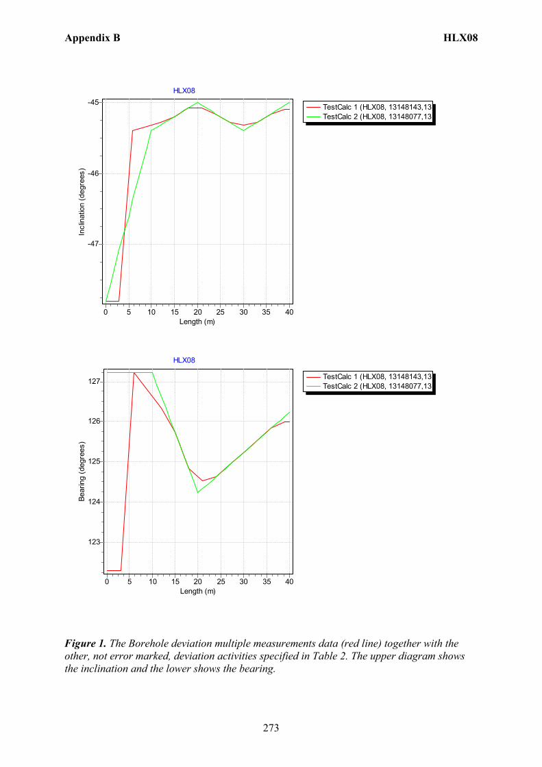
Appendix B HLX08
273
TestCalc 1 (HLX08, 13148143,13TestCalc 2 (HLX08, 13148077,13
HLX08
Length (m)4035302520151050
Incl
inat
ion
(deg
rees
)
-45
-46
-47
TestCalc 1 (HLX08, 13148143,13TestCalc 2 (HLX08, 13148077,13
HLX08
Length (m)4035302520151050
Bear
ing
(deg
rees
)
127
126
125
124
123
Figure 1. The Borehole deviation multiple measurements data (red line) together with the other, not error marked, deviation activities specified in Table 2. The upper diagram shows the inclination and the lower shows the bearing.
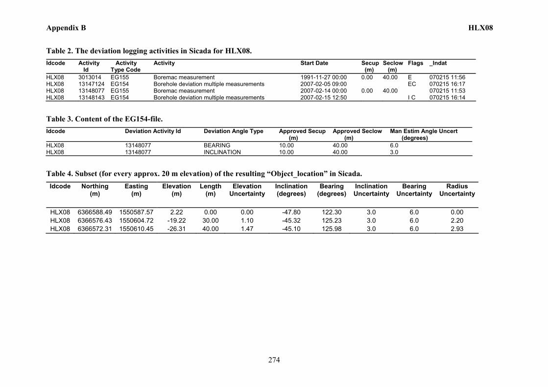
Appendix B HLX08
274
Table 2. The deviation logging activities in Sicada for HLX08. Idcode Activity
Id Activity Type Code
Activity Start Date Secup (m)
Seclow (m)
Flags _Indat
HLX08 3013014 EG155 Boremac measurement 1991-11-27 00:00 0.00 40.00 E 070215 11:56 HLX08 13147124 EG154 Borehole deviation multiple measurements 2007-02-05 09:00 EC 070215 16:17 HLX08 13148077 EG155 Boremac measurement 2007-02-14 00:00 0.00 40.00 070215 11:53 HLX08 13148143 EG154 Borehole deviation multiple measurements 2007-02-15 12:50 I C 070215 16:14
Table 3. Content of the EG154-file. Idcode Deviation Activity Id Deviation Angle Type Approved Secup
(m) Approved Seclow (m)
Man Estim Angle Uncert (degrees)
HLX08 13148077 BEARING 10.00 40.00 6.0 HLX08 13148077 INCLINATION 10.00 40.00 3.0
Table 4. Subset (for every approx. 20 m elevation) of the resulting “Object_location” in Sicada. Idcode Northing
(m) Easting
(m) Elevation
(m) Length
(m) Elevation
Uncertainty Inclination (degrees)
Bearing (degrees)
Inclination Uncertainty
Bearing Uncertainty
Radius Uncertainty
HLX08 6366588.49 1550587.57 2.22 0.00 0.00 -47.80 122.30 3.0 6.0 0.00 HLX08 6366576.43 1550604.72 -19.22 30.00 1.10 -45.32 125.23 3.0 6.0 2.20 HLX08 6366572.31 1550610.45 -26.31 40.00 1.47 -45.10 125.98 3.0 6.0 2.93
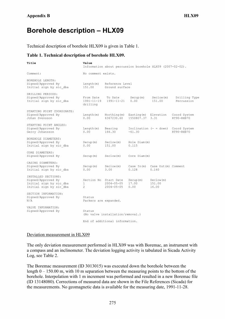
Appendix B HLX09
275
Borehole description – HLX09
Technical description of borehole HLX09 is given in Table 1.
Table 1. Technical description of borehole HLX09. Title Value Information about percussion borehole HLX09 (2007-02-02). Comment: No comment exists. BOREHOLE LENGTH: Signed/Approved By Length(m) Reference Level Initial sign by sic_dba 151.00 Ground surface DRILLING PERIODS: Signed/Approved By From Date To Date Secup(m) Seclow(m) Drilling Type Initial sign by sic_dba 1991-11-19 1991-11-21 0.00 151.00 Percussion
drilling STARTING POINT COORDINATE: Signed/Approved By Length(m) Northing(m) Easting(m) Elevation Coord System Johan Svensson 0.00 6367230.60 1550807.37 3.31 RT90-RHB70 STARTING POINT ANGLES: Signed/Approved By Length(m) Bearing Inclination (- = down) Coord System Gerry Johansson 0.00 166.30 -61.30 RT90-RHB70 BOREHOLE DIAMETERS: Signed/Approved By Secup(m) Seclow(m) Hole Diam(m) Initial sign by sic_dba 0.00 151.00 0.115 CORE DIAMETERS: Signed/Approved By Secup(m) Seclow(m) Core Diam(m) CASING DIAMETERS: Signed/Approved By Secup(m) Seclow(m) Case In(m) Case Out(m) Comment Initial sign by sic_dba 0.00 3.00 0.128 0.140 INSTALLED SECTIONS: Signed/Approved By Section No Start Date Secup(m) Seclow(m) Initial sign by sic_dba 1 2004-05-05 17.00 151.00 Initial sign by sic_dba 2 2004-05-05 0.00 16.00 SECTION INFORMATION: Signed/Approved By Status N/A Packers are expanded. VALVE INFORMATION: Signed/Approved By Status (No valve installation/removal.) End of additional information.
Deviation measurement in HLX09 The only deviation measurement performed in HLX09 was with Boremac, an instrument with a compass and an inclinometer. The deviation logging activity is tabulated in Sicada Activity Log, see Table 2. The Boremac measurement (ID 3013015) was executed down the borehole between the length 0 – 150.00 m, with 10 m separation between the measuring points to the bottom of the borehole. Interpolation with 1 m increment was performed and resulted in a new Boremac file (ID 13148080). Corrections of measured data are shown in the File References (Sicada) for the measurements. No geomagnetic data is available for the measuring date, 1991-11-28.
Appendix B HLX09
276
Borehole deviation multiple measurements. In the calculation of Borehole deviation multiple measurements (ID 13148144) the Boremac measurement (ID 13148080) was used. Table 3 shows the deviation data for the calculation. A subset of the resulting deviation file for every approximately 20 m elevation (from Object_location) is shown in Table 4. When only one measurement was executed with 10 m separation between the readings an inclination uncertainty of 3.0 and bearing uncertainty of 6.0 is used for calculation of the radius uncertainty for every measuring level. Figure 1 show the resulting deviation data together with the other, not error marked, deviation activities listed in Table 2.
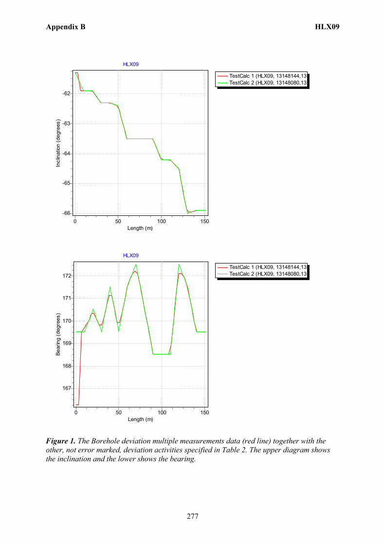
Appendix B HLX09
277
TestCalc 1 (HLX09, 13148144,13TestCalc 2 (HLX09, 13148080,13
HLX09
Length (m)150100500
Incl
inat
ion
(deg
rees
)
-62
-63
-64
-65
-66
TestCalc 1 (HLX09, 13148144,13TestCalc 2 (HLX09, 13148080,13
HLX09
Length (m)150100500
Bear
ing
(deg
rees
)
172
171
170
169
168
167
Figure 1. The Borehole deviation multiple measurements data (red line) together with the other, not error marked, deviation activities specified in Table 2. The upper diagram shows the inclination and the lower shows the bearing.

Appendix B HLX09
278
Table 2. The deviation logging activities in Sicada for HLX09. Idcode Activity
Id Activity Type Code
Activity Start Date Secup (m)
Seclow (m)
Flags _Indat
HLX09 3013015 EG155 Boremac measurement 1991-11-28 00:00 0.00 150.00 E 070215 11:56 HLX09 13147125 EG154 Borehole deviation multiple measurements 2007-02-02 15:45 EC 070215 16:17 HLX09 13148080 EG155 Boremac measurement 2007-02-14 00:00 0.00 150.00 070215 11:53 HLX09 13148144 EG154 Borehole deviation multiple measurements 2007-02-15 12:55 I C 070215 16:15
Table 3. Content of the EG154-file. Idcode Deviation Activity Id Deviation Angle Type Approved Secup
(m) Approved Seclow (m)
Man Estim Angle Uncert (degrees)
HLX09 13148080 BEARING 10.00 150.00 6.0 HLX09 13148080 INCLINATION 10.00 150.00 3.0
Table 4. Subset (for every approx. 20 m elevation) of the resulting “Object_location” in Sicada. Idcode Northing
(m) Easting
(m) Elevation
(m) Length
(m) Elevation
Uncertainty Inclination (degrees)
Bearing (degrees)
Inclination Uncertainty
Bearing Uncertainty
Radius Uncertainty
HLX09 6367230.60 1550807.37 3.31 0.00 0.00 -61.30 166.30 3.0 6.0 0.00 HLX09 6367218.08 1550809.72 -20.49 27.00 0.67 -62.18 169.83 3.0 6.0 1.41 HLX09 6367208.46 1550811.34 -39.09 48.00 1.18 -62.38 169.93 3.0 6.0 2.51 HLX09 6367197.76 1550812.99 -60.51 72.00 1.74 -63.50 172.13 3.0 6.0 3.77 HLX09 6367188.54 1550814.60 -79.30 93.00 2.23 -63.71 168.53 3.0 6.0 4.87 HLX09 6367178.27 1550816.61 -100.90 117.00 2.78 -64.41 171.33 3.0 6.0 6.12 HLX09 6367169.62 1550817.90 -119.99 138.00 3.23 -65.92 169.93 3.0 6.0 7.22 HLX09 6367164.40 1550818.87 -131.86 151.00 3.51 -65.90 169.53 3.0 6.0 7.90
Appendix B HLX10
279
Borehole description – HLX10
Technical description of borehole HLX10 is given in Table 1.
Table 1. Technical description of borehole HLX10. Title Value Information about percussion borehole HLX10 (2007-05-16). Comment: Drill water well used for drilling KLX02 BOREHOLE LENGTH: Signed/Approved By Length(m) Reference Level Stefan Sehlstedt 85.00 Unknown DRILLING PERIODS: Signed/Approved By From Date To Date Secup(m) Seclow(m) Drilling Type Stefan Sehlstedt 1992-09-30 1992-09-30 0.00 85.00 Percussion
drilling STARTING POINT COORDINATE: Signed/Approved By Length(m) Northing(m) Easting(m) Elevation Coord System Gerry Johansson 0.00 6366635.80 1549140.14 11.74 RT90-RHB70 STARTING POINT ANGLES: Signed/Approved By Length(m) Bearing Inclination (- = down) Coord System Gerry Johansson 0.00 176.67 -68.69 RT90-RHB70 BOREHOLE DIAMETERS: Signed/Approved By Secup(m) Seclow(m) Hole Diam(m) Stefan Sehlstedt 0.00 85.00 0.137 CORE DIAMETERS: Signed/Approved By Secup(m) Seclow(m) Core Diam(m) CASING DIAMETERS: Signed/Approved By Secup(m) Seclow(m) Case In(m) Case Out(m) Comment Stefan Sehlstedt 0.00 3.00 INSTALLED SECTIONS: Signed/Approved By Section No Start Date Secup(m) Seclow(m) SECTION INFORMATION: Signed/Approved By Status N/A Packers are released. VALVE INFORMATION: Signed/Approved By Status (No valve installation/removal.) End of additional information.
Borehole direction surveying in HLX10 There is no deviation measurement performed in HLX10. Only the borehole direction surveying was performed from the start of the borehole. Here the starting bearing and inclination is presented in Table 1. Borehole deviation multiple measurements. In the calculation of Borehole deviation multiple measurements (ID 13149809) the borehole direction surveying (ID 13052169) from start of the borehole was used, Table 2. Table 3 shows the deviation data for the calculation.

Appendix B HLX10
280
A subset of the resulting deviation file from Object_location is shown in Table 4. The uncertainty in inclination is calculated according to: –0.000092*(borehole_length)2 + 0.049*borehole length + 1.16 + 1.8. The uncertainty in bearing is calculated according to: 0.05*borehole_length + 2.5 + 4.9. The borehole deviation multiple measurement (ID 13146882) was error marked and replaced with (ID 13149809) which was based on the uncertainty calculation above. Figure 1 show the inclination and bearing of the borehole plotted as a straight line.

Appendix B HLX10
281
TestCalc 1 (HLX10, 13149809,13
HLX10
Length (m)80706050403020100
Incl
inat
ion
(deg
rees
)-62
-63
-64
-65
-66
-67
-68
-69
-70
-71
-72
-73
-74
-75
TestCalc 1 (HLX10, 13149809,13
HLX10
Length (m)80706050403020100
Incl
inat
ion
(deg
rees
)
-62
-63
-64
-65
-66
-67
-68
-69
-70
-71
-72
-73
-74
-75
Figure 1. The Borehole deviation multiple measurements data (red line) plotted as a straight line. The upper diagram shows the inclination and the lower shows the bearing.

Appendix B HLX10
282
Table 2. Borehole deviation multiple measurements in Sicada for HLX10. Idcode Activity
Id Activity Type Code
Activity Start Date Secup (m)
Seclow (m)
Flags _Indat
HLX10 13146882 EG154 Borehole deviation multiple measurements 2007-02-02 15:20 EC 070220 11:09 HLX10 13149809 EG154 Borehole deviation multiple measurements 2007-02-19 11:45 I C 070220 13:07
Table 3. Content of the EG154-file. Idcode Deviation Activity Id Deviation Angle Type Approved Secup
(m) Approved Seclow (m)
Man Estim Angle Uncert (degrees)
HLX10 13052169 BEARING 0.00 0.00 11.65 HLX10 13052169 INCLINATION 0.00 0.00 6.46
Table 4. Subset of the resulting “Object_location” in Sicada. Idcode Northing
(m) Easting (m) Elevation
(m) Length
(m) Elevation
UncertaintyInclination (degrees)
Bearing (degrees)
Inclination Uncertainty
Bearing Uncertainty
Radius Uncertainty
HLX10 6366635.80 1549140.14 11.74 0.00 0.00 -68.69 176.67 6.5 11.7 0.00 HLX10 6366634.71 1549140.20 8.94 3.00 0.12 -68.69 176.67 6.5 11.7 0.34 HLX10 6366604.96 1549141.93 -67.45 85.00 3.48 -68.69 176.67 6.5 11.7 9.56
Appendix B HLX11
283
Borehole description – HLX11
Technical description of borehole HLX11 is given in Table 1.
Table 1. Technical description of borehole HLX11. Title Value Information about percussion borehole HLX11 (2007-02-02). Comment: No comment exists. BOREHOLE LENGTH: Signed/Approved By Length(m) Reference Level Stefan Sehlstedt 70.00 Unknown DRILLING PERIODS: Signed/Approved By From Date To Date Secup(m) Seclow(m) Drilling Type Stefan Sehlstedt 1992-10-01 1992-10-01 0.00 70.00 Percussion
drilling STARTING POINT COORDINATE: Signed/Approved By Length(m) Northing(m) Easting(m) Elevation Coord System Gerry Johansson 0.00 6366595.82 1549091.99 13.15 RT90-RHB70 STARTING POINT ANGLES: Signed/Approved By Length(m) Bearing Inclination (- = down) Coord System Gerry Johansson 0.00 23.16 -68.49 RT90-RHB70 BOREHOLE DIAMETERS: Signed/Approved By Secup(m) Seclow(m) Hole Diam(m) Stefan Sehlstedt 0.00 70.00 0.139 CORE DIAMETERS: Signed/Approved By Secup(m) Seclow(m) Core Diam(m) CASING DIAMETERS: Signed/Approved By Secup(m) Seclow(m) Case In(m) Case Out(m) Comment Stefan Sehlstedt 0.00 6.00 INSTALLED SECTIONS: Signed/Approved By Section No Start Date Secup(m) Seclow(m) Maria Eriksson 1 2005-10-25 14.00 70.00 Maria Eriksson 2 2005-10-25 0.00 13.00 SECTION INFORMATION: Signed/Approved By Status N/A Packers are expanded. VALVE INFORMATION: Signed/Approved By Status (No valve installation/removal.) End of additional information.
Borehole direction surveying in HLX11 There is no deviation measurement performed in HLX11. Only the borehole direction surveying was performed from the start of the borehole. Here the starting bearing and inclination is presented in Table 1. Borehole deviation multiple measurements. In the calculation of Borehole deviation multiple measurements (ID 13149808) the borehole direction surveying (ID 13052170) from start of the borehole was used, Table 2. Table 3 shows the deviation data for the calculation.

Appendix B HLX11
284
A subset of the resulting deviation file from Object_location is shown in Table 4. The uncertainty in inclination is calculated according to: –0.000092*(borehole_length)2 + 0.049*borehole length + 1.16 + 1.8. The uncertainty in bearing is calculated according to: 0.05*borehole_length + 2.5 + 4.9. The borehole deviation multiple measurement (ID 13146883) was error marked and replaced with (ID 13149808) which was based on the uncertainty calculation above. Figure 1 show the inclination and bearing of the borehole plotted as a straight line.
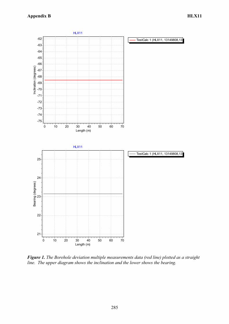
Appendix B HLX11
285
TestCalc 1 (HLX11, 13149808,13
HLX11
Length (m)706050403020100
Incl
inat
ion
(deg
rees
)-62
-63
-64
-65
-66
-67
-68
-69
-70
-71
-72
-73
-74
-75
TestCalc 1 (HLX11, 13149808,13
HLX11
Length (m)706050403020100
Bear
ing
(deg
rees
)
25
24
23
22
21
Figure 1. The Borehole deviation multiple measurements data (red line) plotted as a straight line. The upper diagram shows the inclination and the lower shows the bearing.
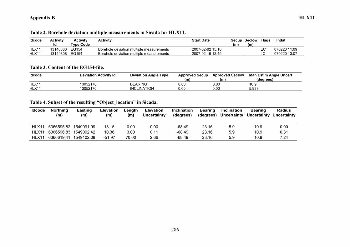
Appendix B HLX11
286
Table 2. Borehole deviation multiple measurements in Sicada for HLX11. Idcode Activity
Id Activity Type Code
Activity Start Date Secup (m)
Seclow (m)
Flags _Indat
HLX11 13146883 EG154 Borehole deviation multiple measurements 2007-02-02 15:10 EC 070220 11:09 HLX11 13149808 EG154 Borehole deviation multiple measurements 2007-02-19 12:45 I C 070220 13:07
Table 3. Content of the EG154-file. Idcode Deviation Activity Id Deviation Angle Type Approved Secup
(m) Approved Seclow (m)
Man Estim Angle Uncert (degrees)
HLX11 13052170 BEARING 0.00 0.00 10.9 HLX11 13052170 INCLINATION 0.00 0.00 5.939
Table 4. Subset of the resulting “Object_location” in Sicada. Idcode Northing
(m) Easting
(m) Elevation
(m) Length
(m) Elevation
Uncertainty Inclination (degrees)
Bearing (degrees)
Inclination Uncertainty
Bearing Uncertainty
Radius Uncertainty
HLX11 6366595.82 1549091.99 13.15 0.00 0.00 -68.49 23.16 5.9 10.9 0.00 HLX11 6366596.83 1549092.42 10.36 3.00 0.11 -68.49 23.16 5.9 10.9 0.31 HLX11 6366619.41 1549102.08 -51.97 70.00 2.66 -68.49 23.16 5.9 10.9 7.24
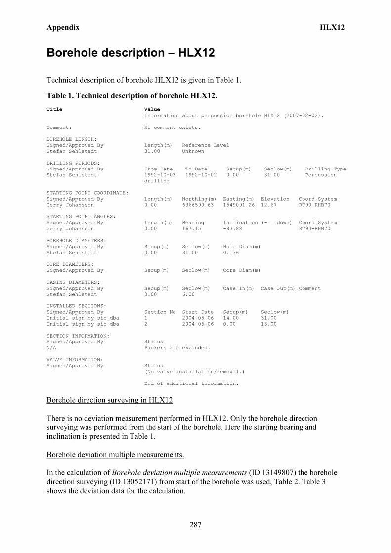
Appendix HLX12
287
Borehole description – HLX12
Technical description of borehole HLX12 is given in Table 1.
Table 1. Technical description of borehole HLX12. Title Value Information about percussion borehole HLX12 (2007-02-02). Comment: No comment exists. BOREHOLE LENGTH: Signed/Approved By Length(m) Reference Level Stefan Sehlstedt 31.00 Unknown DRILLING PERIODS: Signed/Approved By From Date To Date Secup(m) Seclow(m) Drilling Type Stefan Sehlstedt 1992-10-02 1992-10-02 0.00 31.00 Percussion
drilling STARTING POINT COORDINATE: Signed/Approved By Length(m) Northing(m) Easting(m) Elevation Coord System Gerry Johansson 0.00 6366590.63 1549091.26 12.67 RT90-RHB70 STARTING POINT ANGLES: Signed/Approved By Length(m) Bearing Inclination (- = down) Coord System Gerry Johansson 0.00 167.15 -83.88 RT90-RHB70 BOREHOLE DIAMETERS: Signed/Approved By Secup(m) Seclow(m) Hole Diam(m) Stefan Sehlstedt 0.00 31.00 0.136 CORE DIAMETERS: Signed/Approved By Secup(m) Seclow(m) Core Diam(m) CASING DIAMETERS: Signed/Approved By Secup(m) Seclow(m) Case In(m) Case Out(m) Comment Stefan Sehlstedt 0.00 6.00 INSTALLED SECTIONS: Signed/Approved By Section No Start Date Secup(m) Seclow(m) Initial sign by sic_dba 1 2004-05-06 14.00 31.00 Initial sign by sic_dba 2 2004-05-06 0.00 13.00 SECTION INFORMATION: Signed/Approved By Status N/A Packers are expanded. VALVE INFORMATION: Signed/Approved By Status (No valve installation/removal.) End of additional information.
Borehole direction surveying in HLX12 There is no deviation measurement performed in HLX12. Only the borehole direction surveying was performed from the start of the borehole. Here the starting bearing and inclination is presented in Table 1. Borehole deviation multiple measurements. In the calculation of Borehole deviation multiple measurements (ID 13149807) the borehole direction surveying (ID 13052171) from start of the borehole was used, Table 2. Table 3 shows the deviation data for the calculation.
Appendix HLX12
288
A subset of the resulting deviation file from Object_location is shown in Table 4. The uncertainty in inclination is calculated according to: –0.000092*(borehole_length)2 + 0.049*borehole length + 1.16 + 1.8. The uncertainty in bearing is calculated according to: 0.05*borehole_length + 2.5 + 4.9. The borehole deviation multiple measurement (ID 13146884) was error marked and replaced with (ID 13149807) which was based on the uncertainty calculation above. Figure 1 show the inclination and bearing of the borehole plotted as a straight line.
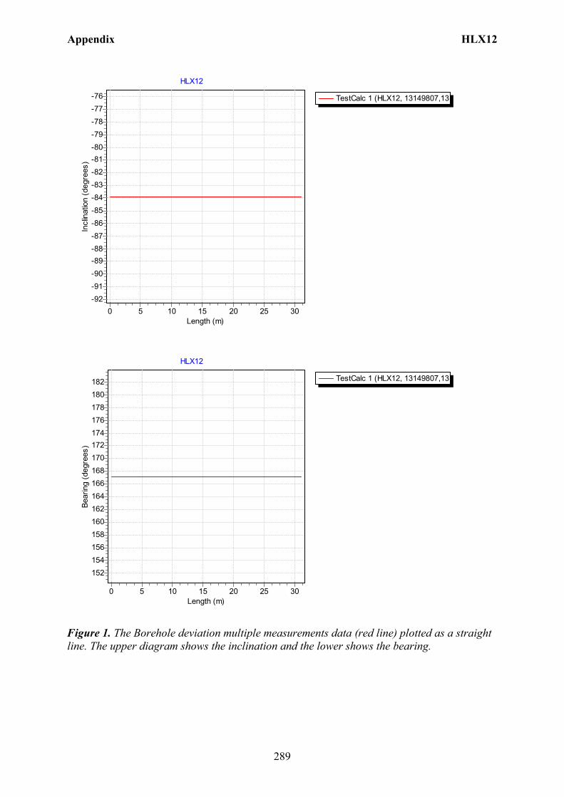
Appendix HLX12
289
TestCalc 1 (HLX12, 13149807,13
HLX12
Length (m)302520151050
Incl
inat
ion
(deg
rees
)-76-77-78-79-80-81-82-83-84-85-86-87-88-89-90-91-92
TestCalc 1 (HLX12, 13149807,13
HLX12
Length (m)302520151050
Bear
ing
(deg
rees
)
182180178176174172170168166164162160158156154152
Figure 1. The Borehole deviation multiple measurements data (red line) plotted as a straight line. The upper diagram shows the inclination and the lower shows the bearing.
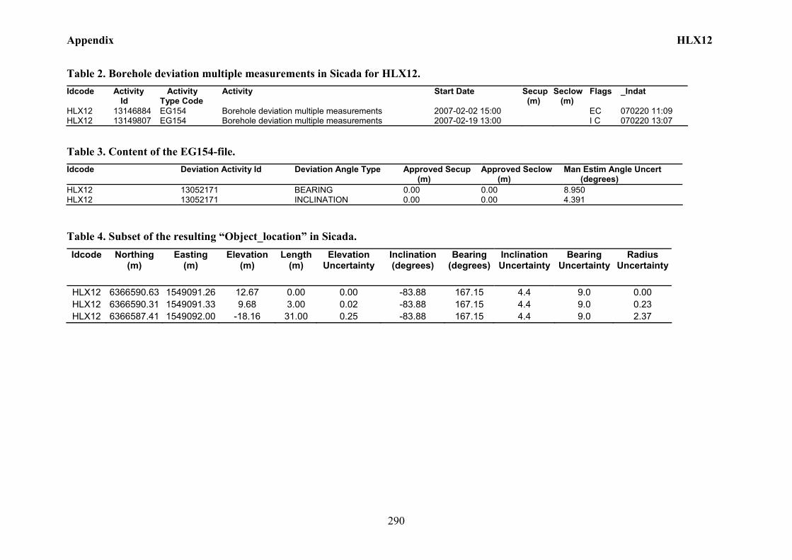
Appendix HLX12
290
Table 2. Borehole deviation multiple measurements in Sicada for HLX12. Idcode Activity
Id Activity Type Code
Activity Start Date Secup (m)
Seclow (m)
Flags _Indat
HLX12 13146884 EG154 Borehole deviation multiple measurements 2007-02-02 15:00 EC 070220 11:09 HLX12 13149807 EG154 Borehole deviation multiple measurements 2007-02-19 13:00 I C 070220 13:07
Table 3. Content of the EG154-file. Idcode Deviation Activity Id Deviation Angle Type Approved Secup
(m) Approved Seclow (m)
Man Estim Angle Uncert (degrees)
HLX12 13052171 BEARING 0.00 0.00 8.950 HLX12 13052171 INCLINATION 0.00 0.00 4.391
Table 4. Subset of the resulting “Object_location” in Sicada. Idcode Northing
(m) Easting
(m) Elevation
(m) Length
(m) Elevation
Uncertainty Inclination (degrees)
Bearing (degrees)
Inclination Uncertainty
Bearing Uncertainty
Radius Uncertainty
HLX12 6366590.63 1549091.26 12.67 0.00 0.00 -83.88 167.15 4.4 9.0 0.00 HLX12 6366590.31 1549091.33 9.68 3.00 0.02 -83.88 167.15 4.4 9.0 0.23 HLX12 6366587.41 1549092.00 -18.16 31.00 0.25 -83.88 167.15 4.4 9.0 2.37
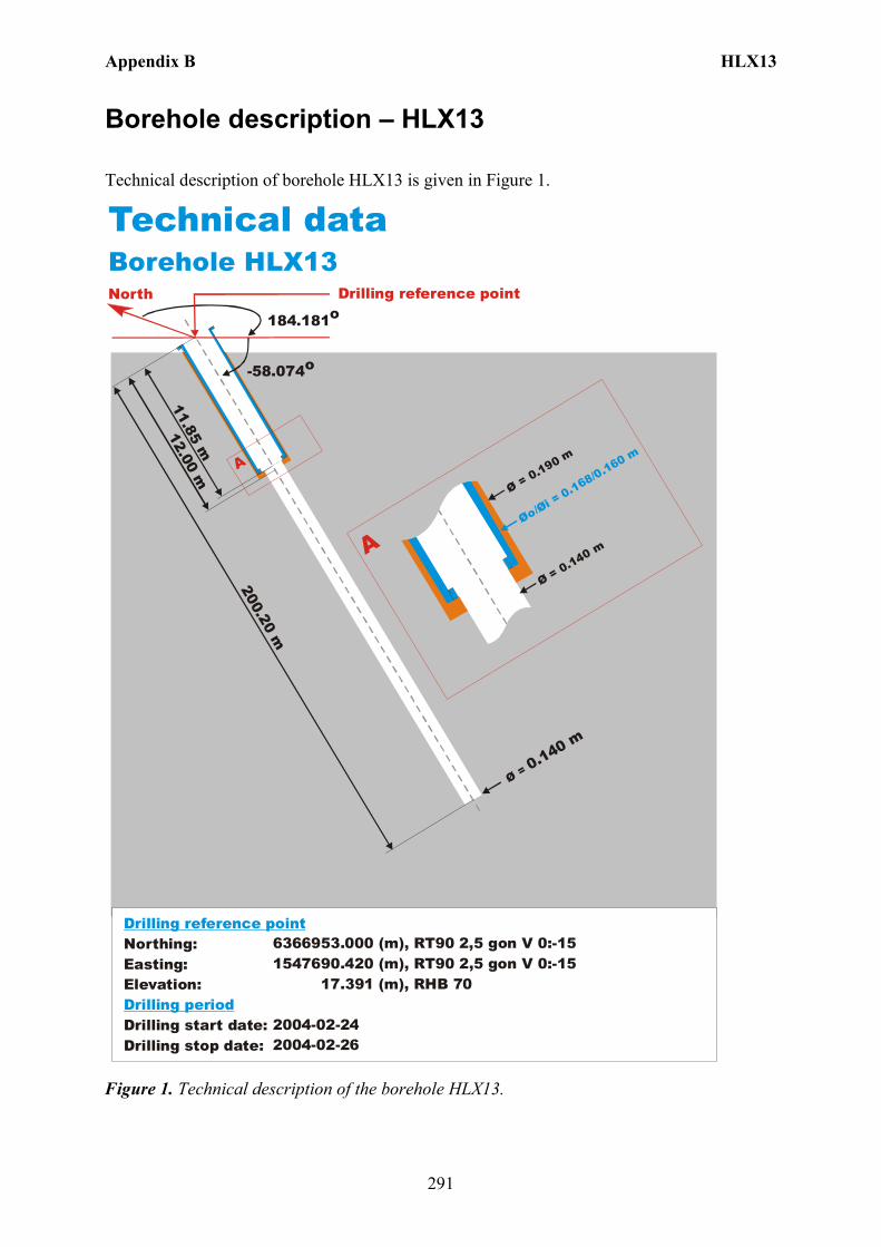
Appendix B HLX13
291
Borehole description – HLX13
Technical description of borehole HLX13 is given in Figure 1.
North
Technical dataBorehole HLX13
6366953.000 (m),(m),
17 (m),
2004-02-242004-02-26
RT90 2,5 gon V 0:-151547690.420 RT90 2,5 gon V 0:-15
.391 RHB 70
-58.074o
Ø = 0.140 m
200.20 m
12.00 m
Øo/Øi = 0.168/0.160 m
Ø = 0.190 m
Ø = 0.140 m
A
A
184.181o
Northing:Easting:Elevation:
Drilling start date:Drilling stop date:
Drilling reference point
Drilling period
11.85 m
Drilling reference point
Figure 1. Technical description of the borehole HLX13.

Appendix B HLX13
292
Deviation measurement in HLX13 The only deviation measurement performed in HLX13 was with the acoustic televiewer. On the data a 31 point median filter was used to reduce oscillation in the bearing. The deviation logging activity is tabulated in Sicada Activity Log, see Table 1. The acoustic televiewer measurement (ID 13145264) is executed between borehole lengths 0 – 197.20 m. No geomagnetic disturbance exceeding 0.5 degrees was observed on the date of the acoustic televiewer measurement, see Figure 2.
Figure 2. The geomagnetic field was observed at the Observatory in Uppsala on 2004-06-03.
Borehole deviation multiple measurements. In the calculation of Borehole deviation multiple measurements (ID 13145602) the acoustic televiewer measurement (ID 13145264) was used. Table 2 shows the deviation data for the calculation. A subset of the resulting deviation file for every approximately 20 m elevation (from Object_location) is shown in Table 3. When only one measurement is used the standard values of inclination uncertainty, 1.8 and bearing uncertainty of 4.9 are used for calculation of the radius uncertainty for every measuring level. Figure 3 show the resulting deviation data together with the other, not error marked, deviation activity listed in Table 1.
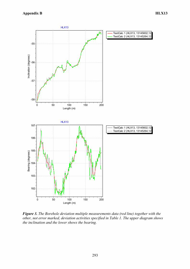
Appendix B HLX13
293
TestCalc 1 (HLX13, 13145602,12TestCalc 2 (HLX13, 13145264,12
HLX13
Length (m)200150100500
Incl
inat
ion
(deg
rees
)
-55
-56
-57
-58
TestCalc 1 (HLX13, 13145602,12TestCalc 2 (HLX13, 13145264,12
HLX13
Length (m)200150100500
Bear
ing
(deg
rees
)
187
186
185
184
183
182
Figure 3. The Borehole deviation multiple measurements data (red line) together with the other, not error marked, deviation activities specified in Table 1. The upper diagram shows the inclination and the lower shows the bearing.
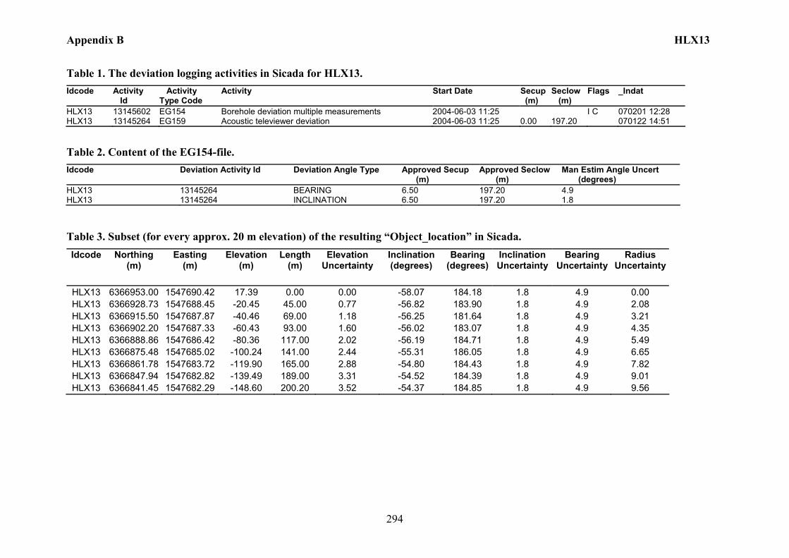
Appendix B HLX13
294
Table 1. The deviation logging activities in Sicada for HLX13. Idcode Activity
Id Activity Type Code
Activity Start Date Secup (m)
Seclow (m)
Flags _Indat
HLX13 13145602 EG154 Borehole deviation multiple measurements 2004-06-03 11:25 I C 070201 12:28 HLX13 13145264 EG159 Acoustic televiewer deviation 2004-06-03 11:25 0.00 197.20 070122 14:51
Table 2. Content of the EG154-file. Idcode Deviation Activity Id Deviation Angle Type Approved Secup
(m) Approved Seclow (m)
Man Estim Angle Uncert (degrees)
HLX13 13145264 BEARING 6.50 197.20 4.9 HLX13 13145264 INCLINATION 6.50 197.20 1.8
Table 3. Subset (for every approx. 20 m elevation) of the resulting “Object_location” in Sicada. Idcode Northing
(m) Easting
(m) Elevation
(m) Length
(m) Elevation
Uncertainty Inclination (degrees)
Bearing (degrees)
Inclination Uncertainty
Bearing Uncertainty
Radius Uncertainty
HLX13 6366953.00 1547690.42 17.39 0.00 0.00 -58.07 184.18 1.8 4.9 0.00 HLX13 6366928.73 1547688.45 -20.45 45.00 0.77 -56.82 183.90 1.8 4.9 2.08 HLX13 6366915.50 1547687.87 -40.46 69.00 1.18 -56.25 181.64 1.8 4.9 3.21 HLX13 6366902.20 1547687.33 -60.43 93.00 1.60 -56.02 183.07 1.8 4.9 4.35 HLX13 6366888.86 1547686.42 -80.36 117.00 2.02 -56.19 184.71 1.8 4.9 5.49 HLX13 6366875.48 1547685.02 -100.24 141.00 2.44 -55.31 186.05 1.8 4.9 6.65 HLX13 6366861.78 1547683.72 -119.90 165.00 2.88 -54.80 184.43 1.8 4.9 7.82 HLX13 6366847.94 1547682.82 -139.49 189.00 3.31 -54.52 184.39 1.8 4.9 9.01 HLX13 6366841.45 1547682.29 -148.60 200.20 3.52 -54.37 184.85 1.8 4.9 9.56
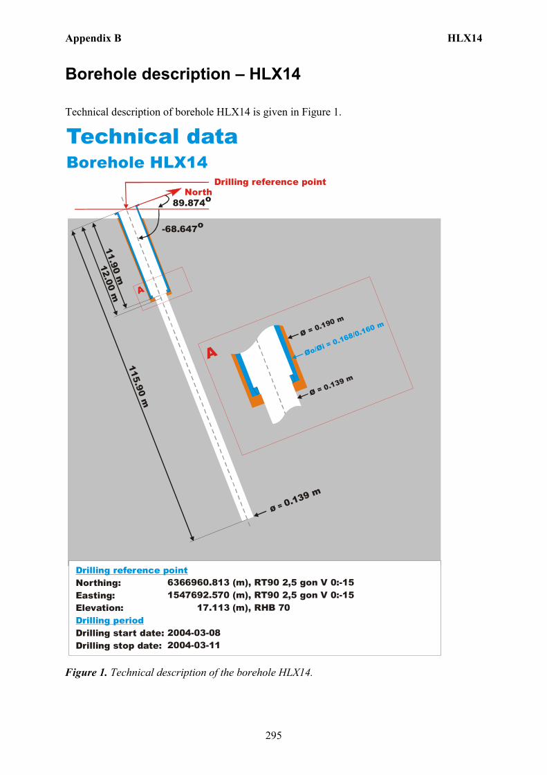
Appendix B HLX14
295
Borehole description – HLX14
Technical description of borehole HLX14 is given in Figure 1.
North
Technical dataBorehole HLX14
6366960.813 (m),(m),
17 (m),
2004-03-082004-03-11
RT90 2,5 gon V 0:-151547692.570 RT90 2,5 gon V 0:-15
.113 RHB 70
-68.647o
Ø = 0.139 m
115.90 m
12.00 m
Øo/Øi = 0.168/0.160 mØ = 0.190 m
Ø = 0.139 m
A
A
89.874o
Northing:Easting:Elevation:
Drilling start date:Drilling stop date:
Drilling reference point
Drilling period
11.90 m
Drilling reference point
Figure 1. Technical description of the borehole HLX14.
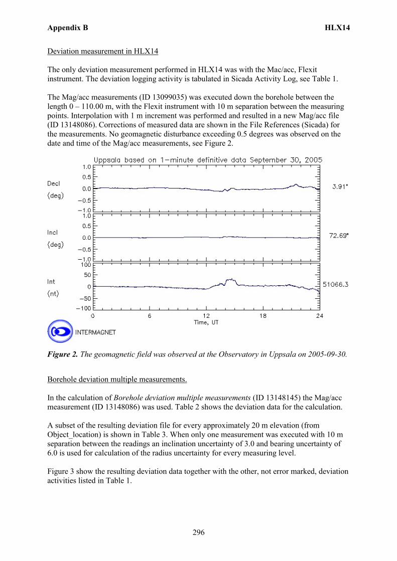
Appendix B HLX14
296
Deviation measurement in HLX14 The only deviation measurement performed in HLX14 was with the Mac/acc, Flexit instrument. The deviation logging activity is tabulated in Sicada Activity Log, see Table 1. The Mag/acc measurements (ID 13099035) was executed down the borehole between the length 0 – 110.00 m, with the Flexit instrument with 10 m separation between the measuring points. Interpolation with 1 m increment was performed and resulted in a new Mag/acc file (ID 13148086). Corrections of measured data are shown in the File References (Sicada) for the measurements. No geomagnetic disturbance exceeding 0.5 degrees was observed on the date and time of the Mag/acc measurements, see Figure 2.
Figure 2. The geomagnetic field was observed at the Observatory in Uppsala on 2005-09-30.
Borehole deviation multiple measurements. In the calculation of Borehole deviation multiple measurements (ID 13148145) the Mag/acc measurement (ID 13148086) was used. Table 2 shows the deviation data for the calculation. A subset of the resulting deviation file for every approximately 20 m elevation (from Object_location) is shown in Table 3. When only one measurement was executed with 10 m separation between the readings an inclination uncertainty of 3.0 and bearing uncertainty of 6.0 is used for calculation of the radius uncertainty for every measuring level. Figure 3 show the resulting deviation data together with the other, not error marked, deviation activities listed in Table 1.
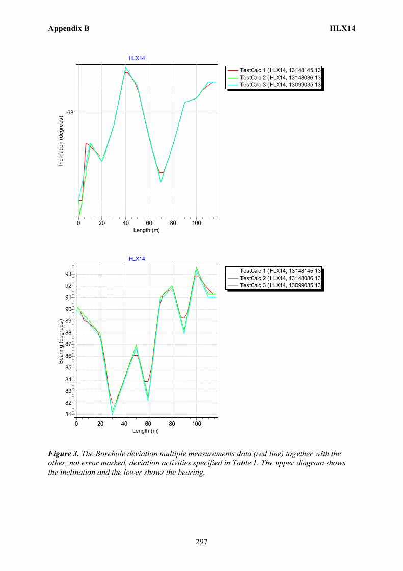
Appendix B HLX14
297
TestCalc 1 (HLX14, 13148145,13TestCalc 2 (HLX14, 13148086,13TestCalc 3 (HLX14, 13099035,13
HLX14
Length (m)100806040200
Incl
inat
ion
(deg
rees
) -68
TestCalc 1 (HLX14, 13148145,13TestCalc 2 (HLX14, 13148086,13TestCalc 3 (HLX14, 13099035,13
HLX14
Length (m)100806040200
Bear
ing
(deg
rees
)
93
92
91
90
89
88
87
86
85
84
83
82
81
Figure 3. The Borehole deviation multiple measurements data (red line) together with the other, not error marked, deviation activities specified in Table 1. The upper diagram shows the inclination and the lower shows the bearing.
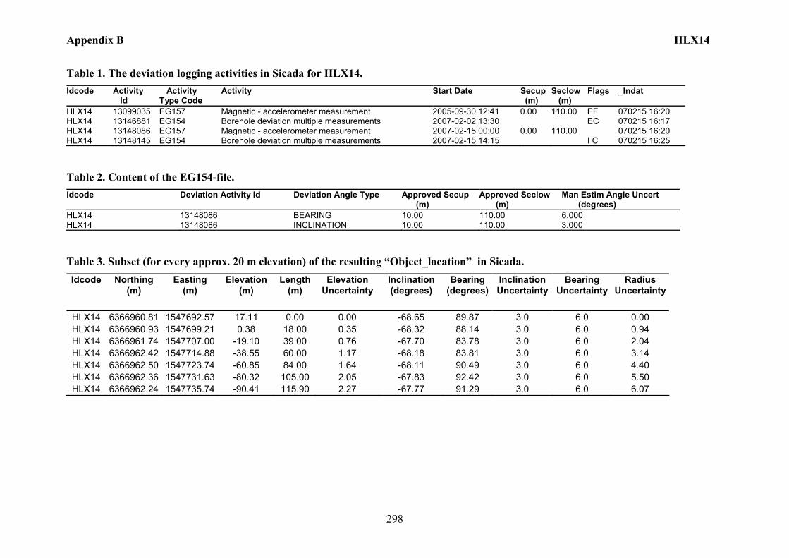
Appendix B HLX14
298
Table 1. The deviation logging activities in Sicada for HLX14. Idcode Activity
Id Activity Type Code
Activity Start Date Secup (m)
Seclow (m)
Flags _Indat
HLX14 13099035 EG157 Magnetic - accelerometer measurement 2005-09-30 12:41 0.00 110.00 EF 070215 16:20 HLX14 13146881 EG154 Borehole deviation multiple measurements 2007-02-02 13:30 EC 070215 16:17 HLX14 13148086 EG157 Magnetic - accelerometer measurement 2007-02-15 00:00 0.00 110.00 070215 16:20 HLX14 13148145 EG154 Borehole deviation multiple measurements 2007-02-15 14:15 I C 070215 16:25
Table 2. Content of the EG154-file. Idcode Deviation Activity Id Deviation Angle Type Approved Secup
(m) Approved Seclow (m)
Man Estim Angle Uncert (degrees)
HLX14 13148086 BEARING 10.00 110.00 6.000 HLX14 13148086 INCLINATION 10.00 110.00 3.000
Table 3. Subset (for every approx. 20 m elevation) of the resulting “Object_location” in Sicada. Idcode Northing
(m) Easting
(m) Elevation
(m) Length
(m) Elevation
Uncertainty Inclination (degrees)
Bearing (degrees)
Inclination Uncertainty
Bearing Uncertainty
Radius Uncertainty
HLX14 6366960.81 1547692.57 17.11 0.00 0.00 -68.65 89.87 3.0 6.0 0.00 HLX14 6366960.93 1547699.21 0.38 18.00 0.35 -68.32 88.14 3.0 6.0 0.94 HLX14 6366961.74 1547707.00 -19.10 39.00 0.76 -67.70 83.78 3.0 6.0 2.04 HLX14 6366962.42 1547714.88 -38.55 60.00 1.17 -68.18 83.81 3.0 6.0 3.14 HLX14 6366962.50 1547723.74 -60.85 84.00 1.64 -68.11 90.49 3.0 6.0 4.40 HLX14 6366962.36 1547731.63 -80.32 105.00 2.05 -67.83 92.42 3.0 6.0 5.50 HLX14 6366962.24 1547735.74 -90.41 115.90 2.27 -67.77 91.29 3.0 6.0 6.07
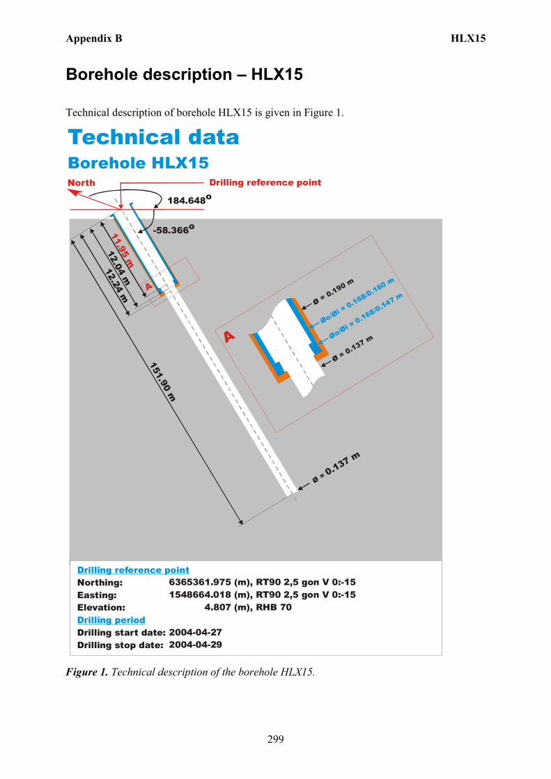
Appendix B HLX15
299
Borehole description – HLX15
Technical description of borehole HLX15 is given in Figure 1.
North
Technical dataBorehole HLX15
6365361.975 (m),(m),
4 (m),
2004-04-272004-04-29
RT90 2,5 gon V 0:-151548664.018 RT90 2,5 gon V 0:-15
.807 RHB 70
-58.366o
Ø = 0.137 m
151.90 m
12.24 m
Øo/Øi = 0.168/0.160 m
Ø = 0.190 m
Ø = 0.137 m
A
A
184.648o
Northing:Easting:Elevation:
Drilling start date:Drilling stop date:
Drilling reference point
Drilling period
Øo/Øi = 0.168/0.147 m
12.04 m11.95 m
Drilling reference point
Figure 1. Technical description of the borehole HLX15.

Appendix B HLX15
300
Deviation measurement in HLX15 The only deviation measurement performed in HLX15 was with the acoustic televiewer. On the data a 31 point median filter was used to reduce oscillation in the bearing. The deviation logging activity is tabulated in Sicada Activity Log, see Table 1. The acoustic televiewer measurement (ID 13145185) is executed between borehole lengths 0 – 147.27 m. The acoustic televiewer measurements (ID 13077082 and 13114892) are error marked measurements which was not median filtered. No geomagnetic disturbance exceeding 0.5 degrees was observed on the date of the acoustic televiewer measurement, see Figure 2.
Figure 2. The geomagnetic field was observed at the Observatory in Uppsala on 2004-06-02.
Borehole deviation multiple measurements. In the calculation of Borehole deviation multiple measurements (ID 13145616) the acoustic televiewer measurement (ID 13145185) was used. Table 2 shows the deviation data for the calculation. A subset of the resulting deviation file for every approximately 20 m elevation (from Object_location) is shown in Table 3. When only one measurement is used the standard values of inclination uncertainty, 1.8 and bearing uncertainty of 4.9 is used for calculation of the radius uncertainty for every measuring level. Figure 3 show the resulting deviation data together with the other, not error marked, deviation activity listed in Table 1.
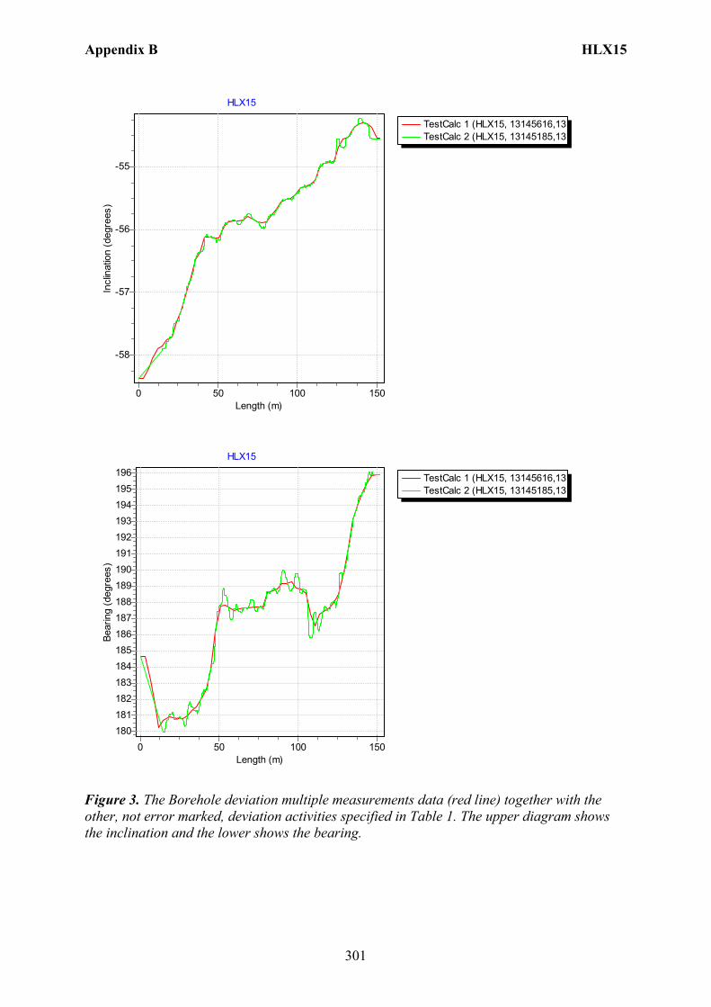
Appendix B HLX15
301
TestCalc 1 (HLX15, 13145616,13TestCalc 2 (HLX15, 13145185,13
HLX15
Length (m)150100500
Incl
inat
ion
(deg
rees
)
-55
-56
-57
-58
TestCalc 1 (HLX15, 13145616,13TestCalc 2 (HLX15, 13145185,13
HLX15
Length (m)150100500
Bear
ing
(deg
rees
)
196195194193192191190189188187186185184183182181180
Figure 3. The Borehole deviation multiple measurements data (red line) together with the other, not error marked, deviation activities specified in Table 1. The upper diagram shows the inclination and the lower shows the bearing.
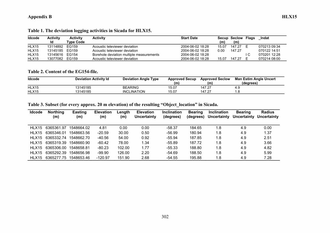
Appendix B HLX15
302
Table 1. The deviation logging activities in Sicada for HLX15. Idcode Activity
Id Activity Type Code
Activity Start Date Secup (m)
Seclow (m)
Flags _Indat
HLX15 13114892 EG159 Acoustic televiewer deviation 2004-06-02 18:28 15.07 147.27 E 070213 09:34 HLX15 13145185 EG159 Acoustic televiewer deviation 2004-06-02 18:28 0.00 147.27 070122 14:51 HLX15 13145616 EG154 Borehole deviation multiple measurements 2004-06-02 18:28 I C 070201 12:28 HLX15 13077082 EG159 Acoustic televiewer deviation 2004-06-02 18:28 15.07 147.27 E 070214 08:00
Table 2. Content of the EG154-file. Idcode Deviation Activity Id Deviation Angle Type Approved Secup
(m) Approved Seclow (m)
Man Estim Angle Uncert (degrees)
HLX15 13145185 BEARING 15.07 147.27 4.9 HLX15 13145185 INCLINATION 15.07 147.27 1.8
Table 3. Subset (for every approx. 20 m elevation) of the resulting “Object_location” in Sicada. Idcode Northing
(m) Easting
(m) Elevation
(m) Length
(m) Elevation
Uncertainty Inclination (degrees)
Bearing (degrees)
Inclination Uncertainty
Bearing Uncertainty
Radius Uncertainty
HLX15 6365361.97 1548664.02 4.81 0.00 0.00 -58.37 184.65 1.8 4.9 0.00 HLX15 6365346.01 1548663.56 -20.59 30.00 0.50 -56.99 180.94 1.8 4.9 1.37 HLX15 6365332.74 1548662.70 -40.56 54.00 0.92 -55.94 187.85 1.8 4.9 2.51 HLX15 6365319.39 1548660.90 -60.42 78.00 1.34 -55.89 187.72 1.8 4.9 3.66 HLX15 6365306.00 1548658.81 -80.23 102.00 1.77 -55.33 188.80 1.8 4.9 4.82 HLX15 6365292.39 1548656.98 -99.90 126.00 2.20 -54.69 188.50 1.8 4.9 5.99 HLX15 6365277.75 1548653.46 -120.97 151.90 2.68 -54.55 195.88 1.8 4.9 7.28
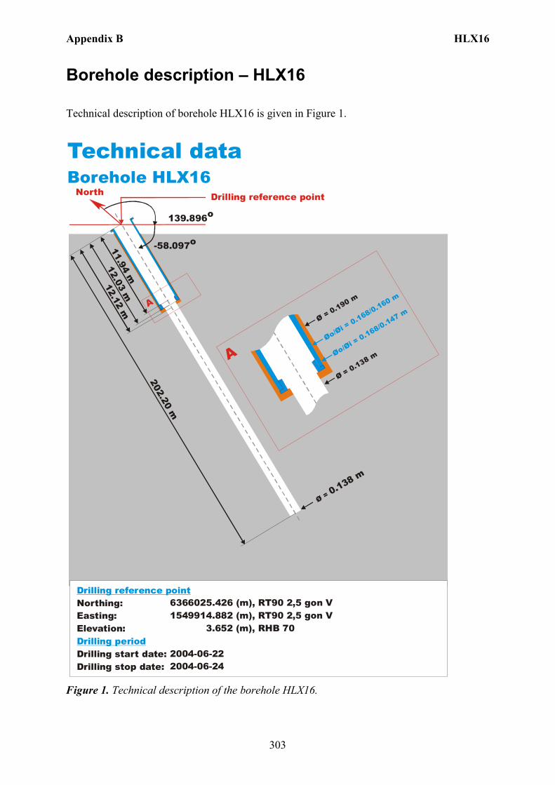
Appendix B HLX16
303
Borehole description – HLX16
Technical description of borehole HLX16 is given in Figure 1.
North
Technical dataBorehole HLX16
6366025.426 (m),(m),
3.652 (m),
2004-06-222004-06-24
1549914.882 RT90 2,5 gon V RHB 70
RT90 2,5 gon V
-58.097o
Ø = 0.138 m
202.20 m
12.12 m
Øo/Øi = 0.168/0.160 m
Ø = 0.190 m
Ø = 0.138 m
A
A
139.896o
Northing:Easting:Elevation:
Drilling start date:Drilling stop date:
Drilling reference point
Drilling period
Øo/Øi = 0.168/0.147 m
12.03 m11.94 m
Drilling reference point
Figure 1. Technical description of the borehole HLX16.
Appendix B HLX16
304
Borehole direction surveying in HLX16 There is no deviation measurement performed in HLX16. Only the borehole direction surveying was performed from the start of the borehole. Here the starting bearing and inclination is presented in Figure 1. Borehole deviation multiple measurements. In the calculation of Borehole deviation multiple measurements (ID 13149806) the borehole direction surveying (ID 13022014) from start of the borehole was used, Table 1. Table 2 shows the deviation data for the calculation. A subset of the resulting deviation file from Object_location is shown in Table 3. The uncertainty in inclination is calculated according to: –0.000092*(borehole_length)2 + 0.049*borehole length + 1.16 + 1.8. The uncertainty in bearing for boreholes of 100-200 m length is set to 12.4 (= 7.5 + 4.9). The borehole deviation multiple measurement (ID 13146885) was error marked and replaced with (ID 13149806) which was based on the uncertainty calculation above. Figure 2 show the inclination and bearing of the borehole plotted as a straight line.
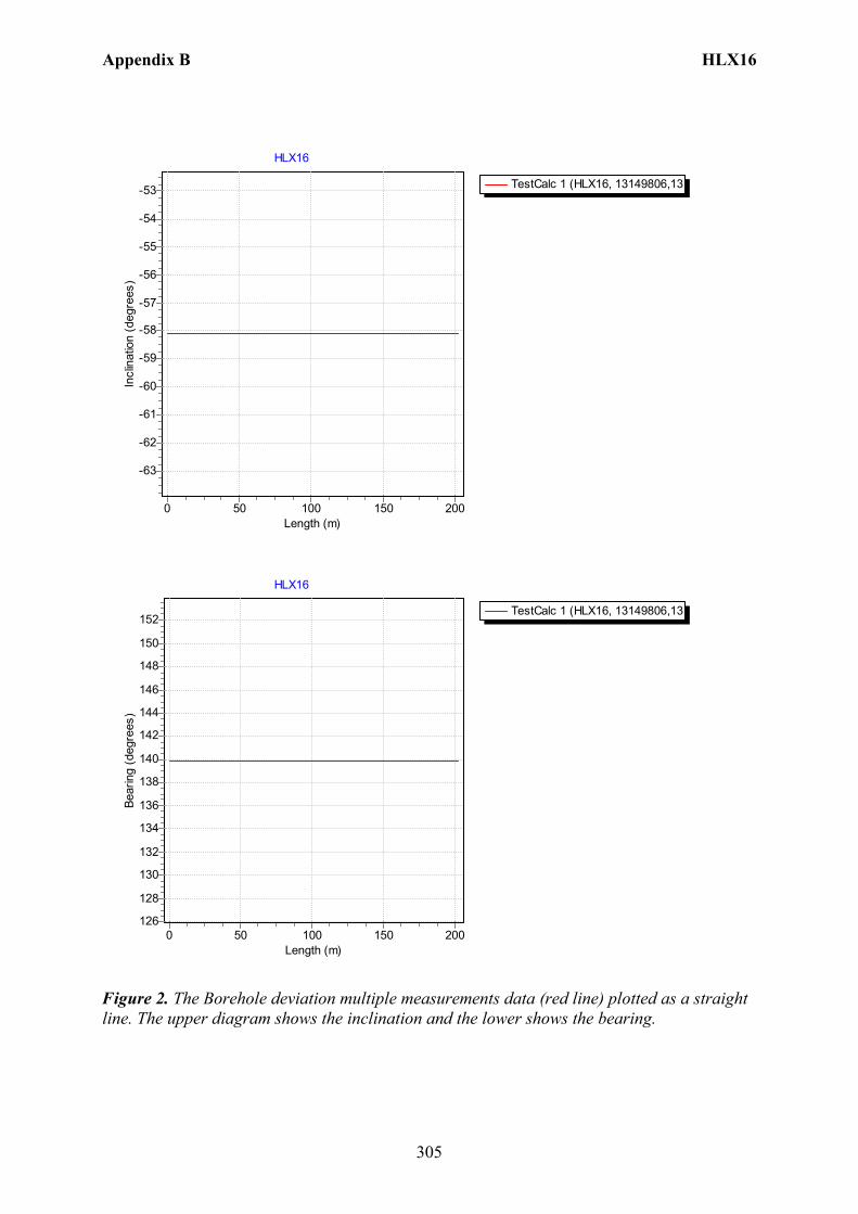
Appendix B HLX16
305
TestCalc 1 (HLX16, 13149806,13
HLX16
Length (m)200150100500
Incl
inat
ion
(deg
rees
)
-53
-54
-55
-56
-57
-58
-59
-60
-61
-62
-63
TestCalc 1 (HLX16, 13149806,13
HLX16
Length (m)200150100500
Bear
ing
(deg
rees
)
152
150
148
146
144
142
140
138
136
134
132
130
128
126
Figure 2. The Borehole deviation multiple measurements data (red line) plotted as a straight line. The upper diagram shows the inclination and the lower shows the bearing.

Appendix B HLX16
306
Table 1. Borehole deviation multiple measurements in Sicada for HLX16. Idcode Activity
Id Activity Type Code
Activity Start Date Secup (m)
Seclow (m)
Flags _Indat
HLX16 13146885 EG154 Borehole deviation multiple measurements 2007-02-02 14:00 EC 070220 11:09 HLX16 13149806 EG154 Borehole deviation multiple measurements 2007-02-19 13:15 I C 070220 13:07
Table 2. Content of the EG154-file. Idcode Deviation Activity Id Deviation Angle Type Approved Secup
(m) Approved Seclow (m)
Man Estim Angle Uncert (degrees)
HLX16 13022014 BEARING 0.00 0.00 12.400 HLX16 13022014 INCLINATION 0.00 0.00 9.106
Table 3. Subset of the resulting “Object_location” in Sicada. Idcode Northing
(m) Easting
(m) Elevation
(m) Length
(m) Elevation
Uncertainty Inclination (degrees)
Bearing (degrees)
Inclination Uncertainty
Bearing Uncertainty
Radius Uncertainty
HLX16 6366025.43 1549914.88 3.65 0.00 0.00 -58.10 139.90 9.1 12.4 0.00 HLX16 6366024.21 1549915.90 1.11 3.00 0.25 -58.10 139.90 9.1 12.4 0.47 HLX16 6365943.69 1549983.72 -168.00 202.20 16.91 -58.10 139.90 9.1 12.4 32.00
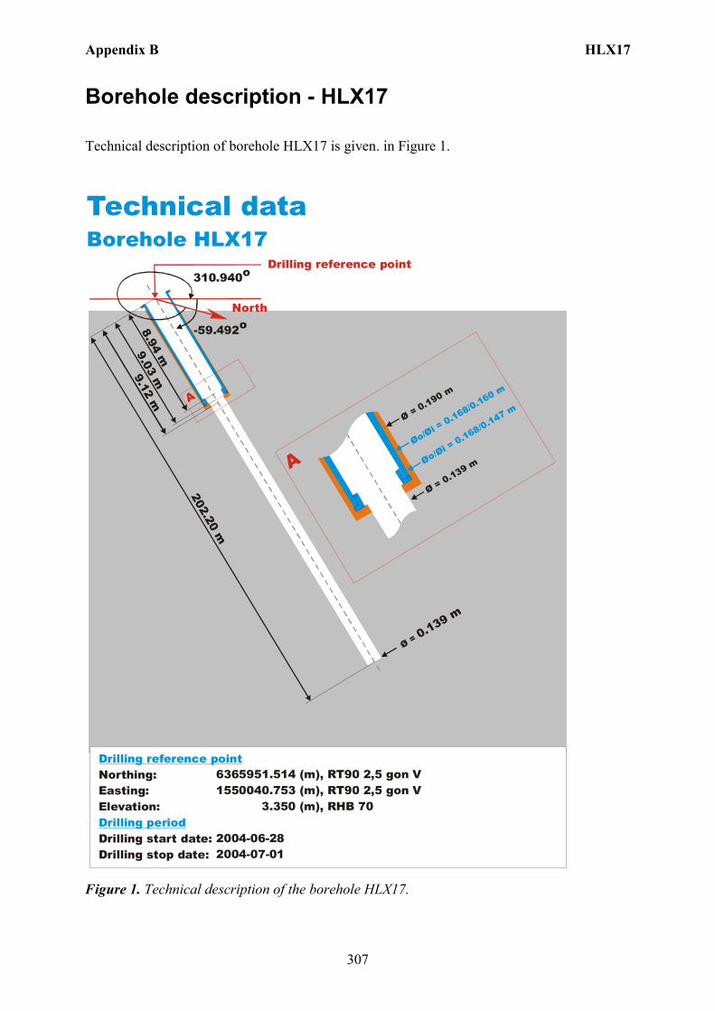
Appendix B HLX17
307
Borehole description - HLX17
Technical description of borehole HLX17 is given. in Figure 1.
North
Technical dataBorehole HLX17
6365951.514 (m),(m),
3.350 (m),
2004-06-282004-07-01
1550040.753 RT90 2,5 gon V RHB 70
RT90 2,5 gon V
-59.492o
Ø = 0.139 m
202.20 m
9.12 m
Øo/Øi = 0.168/0.160 m
Ø = 0.190 m
Ø = 0.139 m
A
A
310.940o
Northing:Easting:Elevation:
Drilling start date:Drilling stop date:
Drilling reference point
Drilling period
Øo/Øi = 0.168/0.147 m
9.03 m8.94 m
Drilling reference point
Figure 1. Technical description of the borehole HLX17.
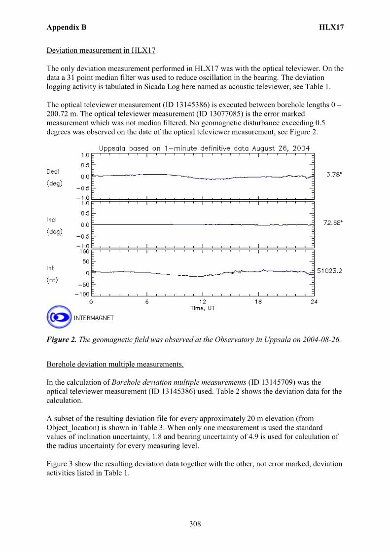
Appendix B HLX17
308
Deviation measurement in HLX17 The only deviation measurement performed in HLX17 was with the optical televiewer. On the data a 31 point median filter was used to reduce oscillation in the bearing. The deviation logging activity is tabulated in Sicada Log here named as acoustic televiewer, see Table 1. The optical televiewer measurement (ID 13145386) is executed between borehole lengths 0 – 200.72 m. The optical televiewer measurement (ID 13077085) is the error marked measurement which was not median filtered. No geomagnetic disturbance exceeding 0.5 degrees was observed on the date of the optical televiewer measurement, see Figure 2.
Figure 2. The geomagnetic field was observed at the Observatory in Uppsala on 2004-08-26.
Borehole deviation multiple measurements. In the calculation of Borehole deviation multiple measurements (ID 13145709) was the optical televiewer measurement (ID 13145386) used. Table 2 shows the deviation data for the calculation. A subset of the resulting deviation file for every approximately 20 m elevation (from Object_location) is shown in Table 3. When only one measurement is used the standard values of inclination uncertainty, 1.8 and bearing uncertainty of 4.9 is used for calculation of the radius uncertainty for every measuring level. Figure 3 show the resulting deviation data together with the other, not error marked, deviation activities listed in Table 1.
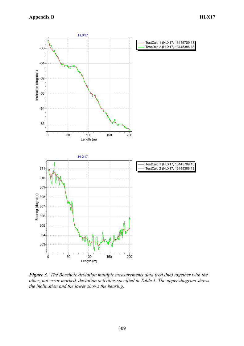
Appendix B HLX17
309
TestCalc 1 (HLX17, 13145709,13TestCalc 2 (HLX17, 13145386,13
HLX17
Length (m)200150100500
Incl
inat
ion
(deg
rees
)
-60
-61
-62
-63
-64
-65
TestCalc 1 (HLX17, 13145709,13TestCalc 2 (HLX17, 13145386,13
HLX17
Length (m)200150100500
Bear
ing
(deg
rees
)
311
310
309
308
307
306
305
304
303
Figure 3. The Borehole deviation multiple measurements data (red line) together with the other, not error marked, deviation activities specified in Table 1. The upper diagram shows the inclination and the lower shows the bearing.
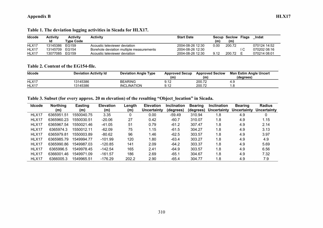
Appendix B HLX17
310
Table 1. The deviation logging activities in Sicada for HLX17. Idcode Activity
Id Activity Type Code
Activity Start Date Secup (m)
Seclow (m)
Flags _Indat
HLX17 13145386 EG159 Acoustic televiewer deviation 2004-08-26 12:30 0.00 200.72 070124 14:52 HLX17 13145709 EG154 Borehole deviation multiple measurements 2004-08-26 12:30 I C 070202 08:16 HLX17 13077085 EG159 Acoustic televiewer deviation 2004-08-26 12:30 9.12 200.72 E 070214 08:01
Table 2. Content of the EG154-file. Idcode Deviation Activity Id Deviation Angle Type Approved Secup
(m) Approved Seclow (m)
Man Estim Angle Uncert (degrees)
HLX17 13145386 BEARING 9.12 200.72 4.9 HLX17 13145386 INCLINATION 9.12 200.72 1.8
Table 3. Subset (for every approx. 20 m elevation) of the resulting “Object_location” in Sicada. Idcode Northing
(m) Easting
(m) Elevation
(m) Length
(m) Elevation
UncertaintyInclination (degrees)
Bearing (degrees)
Inclination Uncertainty
Bearing Uncertainty
Radius Uncertainty
HLX17 6365951.51 1550040.75 3.35 0 0.00 -59.49 310.94 1.8 4.9 0 HLX17 6365960.23 1550030.51 -20.06 27 0.42 -60.7 310.07 1.8 4.9 1.15 HLX17 6365967.54 1550021.46 -41.05 51 0.79 -61.2 307.47 1.8 4.9 2.14 HLX17 6365974.3 1550012.11 -62.09 75 1.15 -61.5 304.27 1.8 4.9 3.13 HLX17 6365979.81 1550003.89 -80.62 96 1.46 -62.5 303.57 1.8 4.9 3.97 HLX17 6365985.79 1549994.77 -101.99 120 1.80 -63.4 303.27 1.8 4.9 4.9 HLX17 6365990.86 1549987.03 -120.85 141 2.09 -64.2 303.37 1.8 4.9 5.69 HLX17 6365996.5 1549978.45 -142.54 165 2.41 -64.9 303.57 1.8 4.9 6.56 HLX17 6366001.46 1549971.09 -161.57 186 2.69 -65.1 304.67 1.8 4.9 7.32 HLX17 6366005.3 1549965.51 -176.29 202.2 2.90 -65.4 304.77 1.8 4.9 7.9
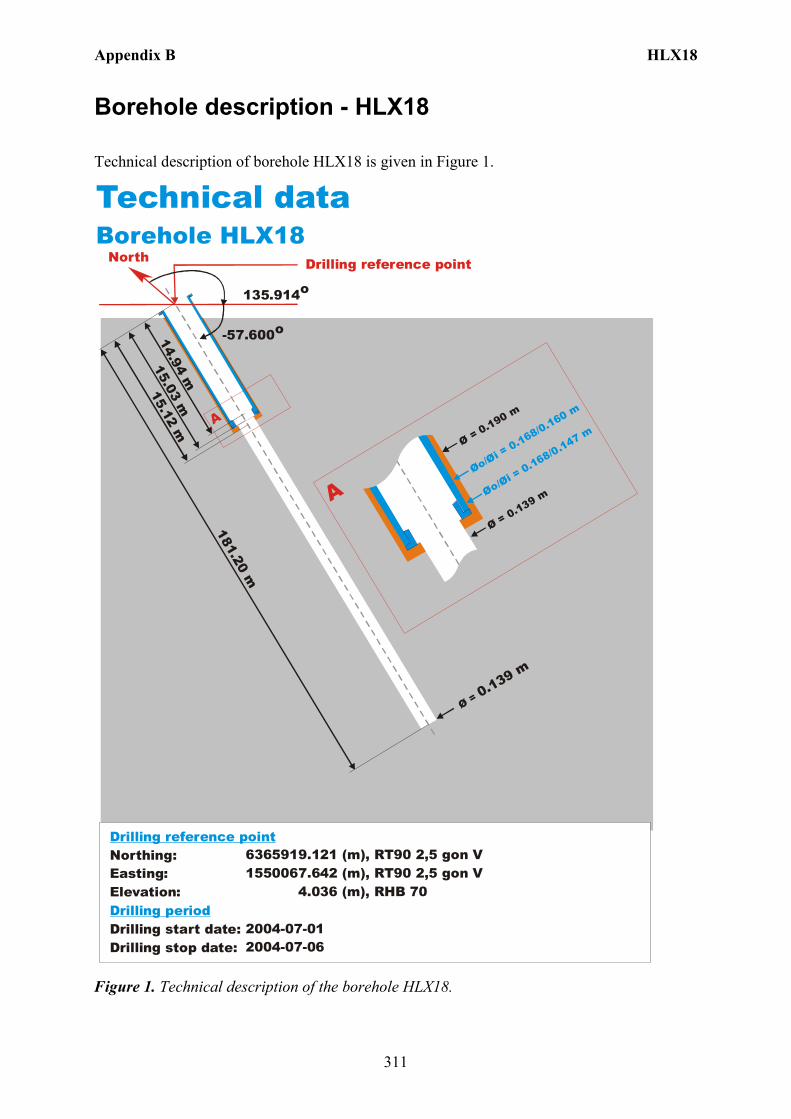
Appendix B HLX18
311
Borehole description - HLX18
Technical description of borehole HLX18 is given in Figure 1.
North
Technical dataBorehole HLX18
6365919.121 (m),(m),
4.036 (m),
2004-07-012004-07-06
1550067.642 RT90 2,5 gon V RHB 70
RT90 2,5 gon V
-57.600o
Ø = 0.139 m
181.20 m
15.12 m
Øo/Øi = 0.168/0.160 m
Ø = 0.190 m
Ø = 0.139 m
A
A
135.914o
Northing:Easting:Elevation:
Drilling start date:Drilling stop date:
Drilling reference point
Drilling period
Øo/Øi = 0.168/0.147 m
15.03 m14.94 m
Drilling reference point
Figure 1. Technical description of the borehole HLX18.
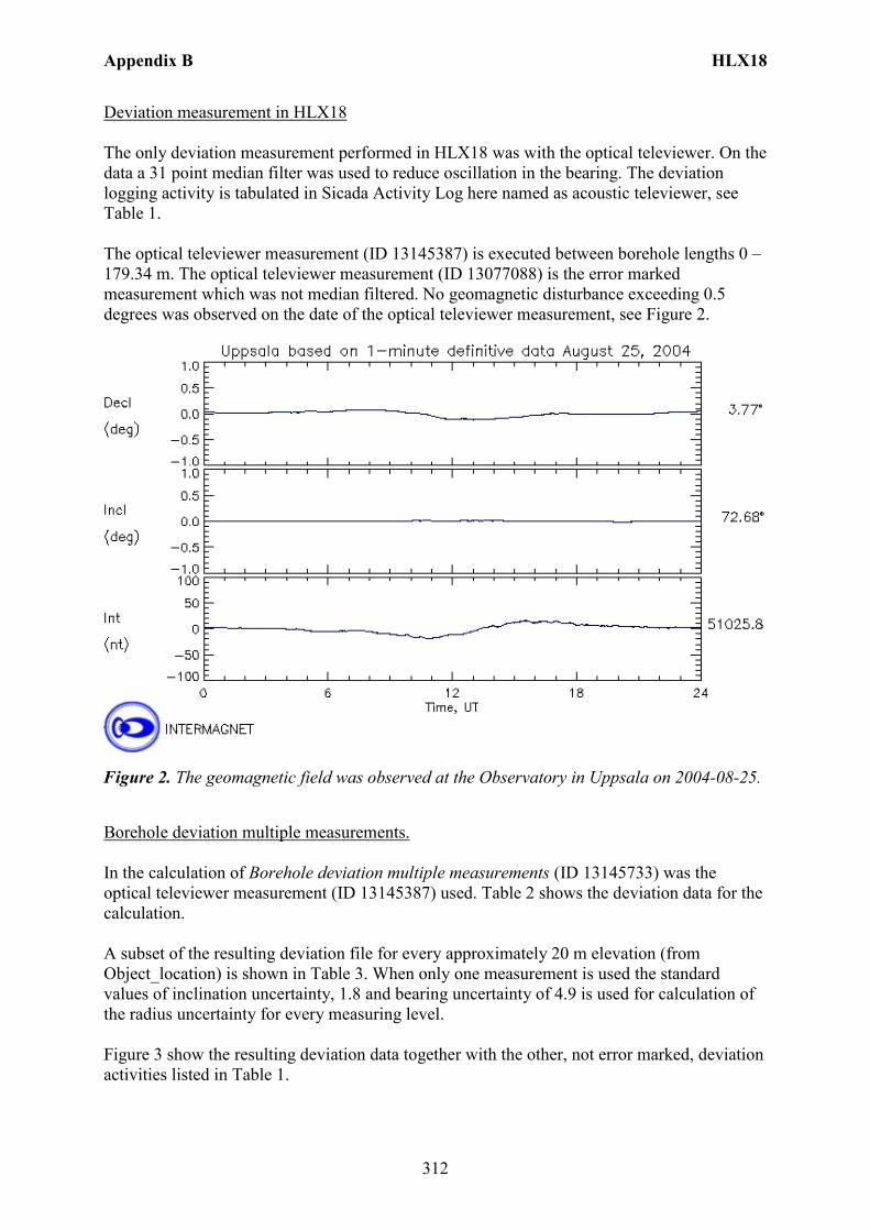
Appendix B HLX18
312
Deviation measurement in HLX18 The only deviation measurement performed in HLX18 was with the optical televiewer. On the data a 31 point median filter was used to reduce oscillation in the bearing. The deviation logging activity is tabulated in Sicada Activity Log here named as acoustic televiewer, see Table 1. The optical televiewer measurement (ID 13145387) is executed between borehole lengths 0 – 179.34 m. The optical televiewer measurement (ID 13077088) is the error marked measurement which was not median filtered. No geomagnetic disturbance exceeding 0.5 degrees was observed on the date of the optical televiewer measurement, see Figure 2.
Figure 2. The geomagnetic field was observed at the Observatory in Uppsala on 2004-08-25.
Borehole deviation multiple measurements. In the calculation of Borehole deviation multiple measurements (ID 13145733) was the optical televiewer measurement (ID 13145387) used. Table 2 shows the deviation data for the calculation. A subset of the resulting deviation file for every approximately 20 m elevation (from Object_location) is shown in Table 3. When only one measurement is used the standard values of inclination uncertainty, 1.8 and bearing uncertainty of 4.9 is used for calculation of the radius uncertainty for every measuring level. Figure 3 show the resulting deviation data together with the other, not error marked, deviation activities listed in Table 1.
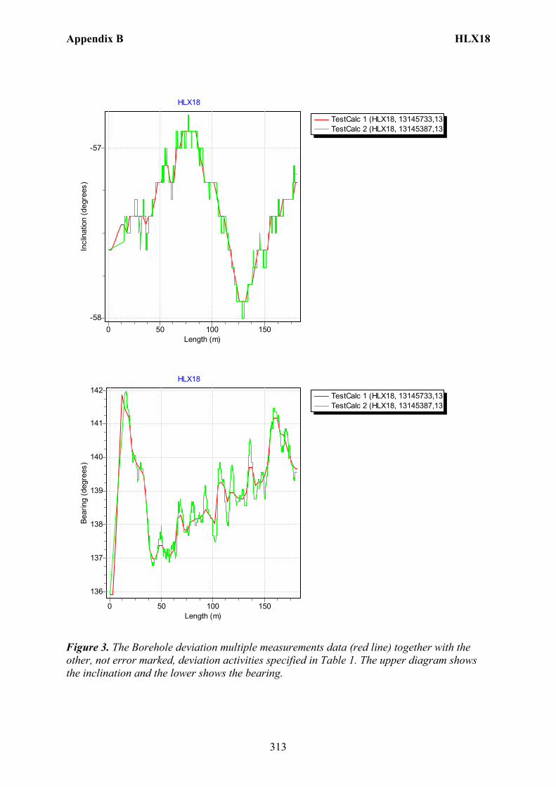
Appendix B HLX18
313
TestCalc 1 (HLX18, 13145733,13TestCalc 2 (HLX18, 13145387,13
HLX18
Length (m)150100500
Incl
inat
ion
(deg
rees
)
-57
-58
TestCalc 1 (HLX18, 13145733,13TestCalc 2 (HLX18, 13145387,13
HLX18
Length (m)150100500
Bear
ing
(deg
rees
)
142
141
140
139
138
137
136
Figure 3. The Borehole deviation multiple measurements data (red line) together with the other, not error marked, deviation activities specified in Table 1. The upper diagram shows the inclination and the lower shows the bearing.
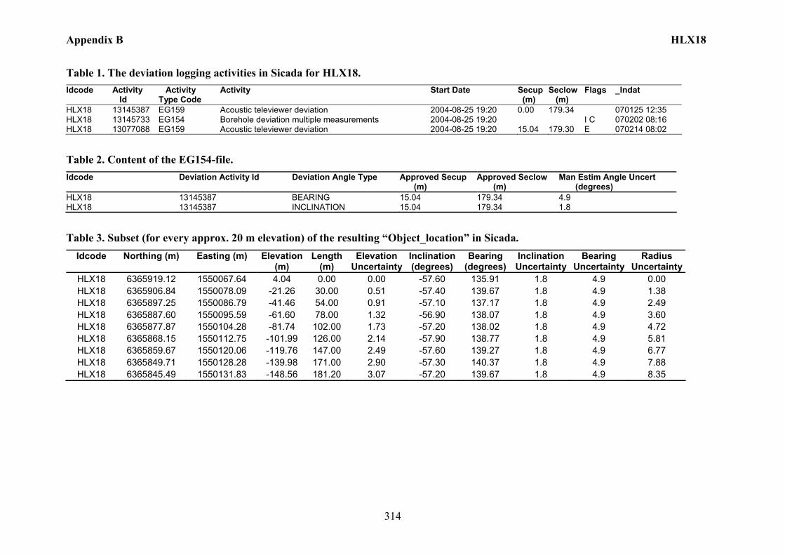
Appendix B HLX18
314
Table 1. The deviation logging activities in Sicada for HLX18. Idcode Activity
Id Activity Type Code
Activity Start Date Secup (m)
Seclow (m)
Flags _Indat
HLX18 13145387 EG159 Acoustic televiewer deviation 2004-08-25 19:20 0.00 179.34 070125 12:35 HLX18 13145733 EG154 Borehole deviation multiple measurements 2004-08-25 19:20 I C 070202 08:16 HLX18 13077088 EG159 Acoustic televiewer deviation 2004-08-25 19:20 15.04 179.30 E 070214 08:02
Table 2. Content of the EG154-file. Idcode Deviation Activity Id Deviation Angle Type Approved Secup
(m) Approved Seclow (m)
Man Estim Angle Uncert (degrees)
HLX18 13145387 BEARING 15.04 179.34 4.9 HLX18 13145387 INCLINATION 15.04 179.34 1.8 Table 3. Subset (for every approx. 20 m elevation) of the resulting “Object_location” in Sicada.
Idcode Northing (m) Easting (m) Elevation (m)
Length (m)
Elevation Uncertainty
Inclination (degrees)
Bearing (degrees)
Inclination Uncertainty
Bearing Uncertainty
Radius Uncertainty
HLX18 6365919.12 1550067.64 4.04 0.00 0.00 -57.60 135.91 1.8 4.9 0.00 HLX18 6365906.84 1550078.09 -21.26 30.00 0.51 -57.40 139.67 1.8 4.9 1.38 HLX18 6365897.25 1550086.79 -41.46 54.00 0.91 -57.10 137.17 1.8 4.9 2.49 HLX18 6365887.60 1550095.59 -61.60 78.00 1.32 -56.90 138.07 1.8 4.9 3.60 HLX18 6365877.87 1550104.28 -81.74 102.00 1.73 -57.20 138.02 1.8 4.9 4.72 HLX18 6365868.15 1550112.75 -101.99 126.00 2.14 -57.90 138.77 1.8 4.9 5.81 HLX18 6365859.67 1550120.06 -119.76 147.00 2.49 -57.60 139.27 1.8 4.9 6.77 HLX18 6365849.71 1550128.28 -139.98 171.00 2.90 -57.30 140.37 1.8 4.9 7.88 HLX18 6365845.49 1550131.83 -148.56 181.20 3.07 -57.20 139.67 1.8 4.9 8.35
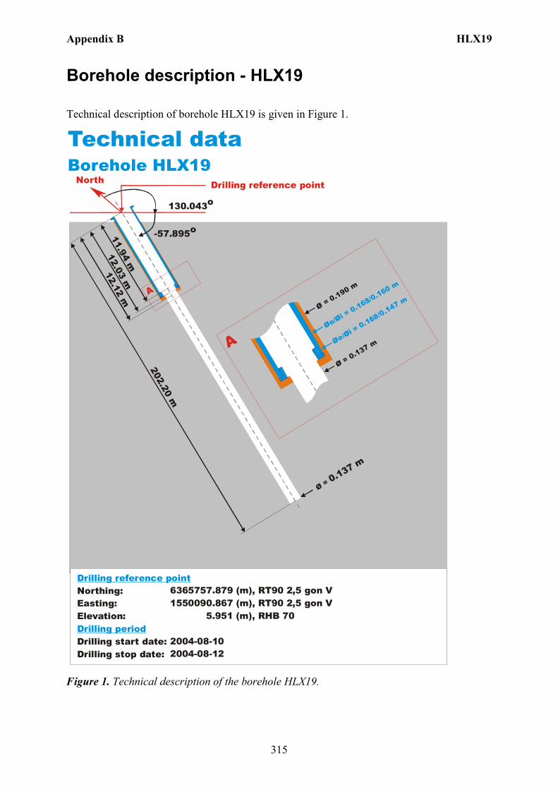
Appendix B HLX19
315
Borehole description - HLX19
Technical description of borehole HLX19 is given in Figure 1.
North
Technical dataBorehole HLX19
6365757.879 (m),(m),
5.951 (m),
2004-08-102004-08-12
1550090.867 RT90 2,5 gon V RHB 70
RT90 2,5 gon V
-57.895o
Ø = 0.137 m
202.20 m
12.12 m
Øo/Øi = 0.168/0.160 m
Ø = 0.190 m
Ø = 0.137 m
A
A
130.043o
Northing:Easting:Elevation:
Drilling start date:Drilling stop date:
Drilling reference point
Drilling period
Øo/Øi = 0.168/0.147 m
12.03 m11.94 m
Drilling reference point
Figure 1. Technical description of the borehole HLX19.
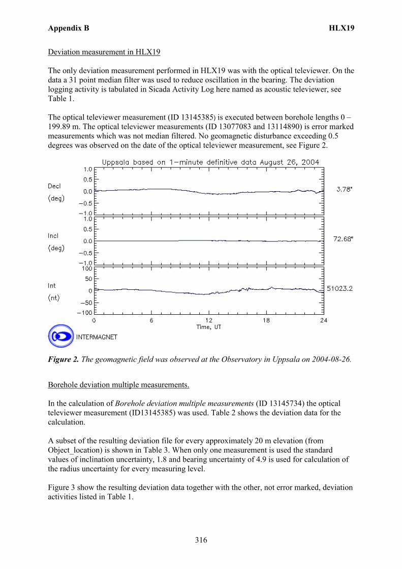
Appendix B HLX19
316
Deviation measurement in HLX19 The only deviation measurement performed in HLX19 was with the optical televiewer. On the data a 31 point median filter was used to reduce oscillation in the bearing. The deviation logging activity is tabulated in Sicada Activity Log here named as acoustic televiewer, see Table 1. The optical televiewer measurement (ID 13145385) is executed between borehole lengths 0 – 199.89 m. The optical televiewer measurements (ID 13077083 and 13114890) is error marked measurements which was not median filtered. No geomagnetic disturbance exceeding 0.5 degrees was observed on the date of the optical televiewer measurement, see Figure 2.
Figure 2. The geomagnetic field was observed at the Observatory in Uppsala on 2004-08-26.
Borehole deviation multiple measurements. In the calculation of Borehole deviation multiple measurements (ID 13145734) the optical televiewer measurement (ID13145385) was used. Table 2 shows the deviation data for the calculation. A subset of the resulting deviation file for every approximately 20 m elevation (from Object_location) is shown in Table 3. When only one measurement is used the standard values of inclination uncertainty, 1.8 and bearing uncertainty of 4.9 is used for calculation of the radius uncertainty for every measuring level. Figure 3 show the resulting deviation data together with the other, not error marked, deviation activities listed in Table 1.
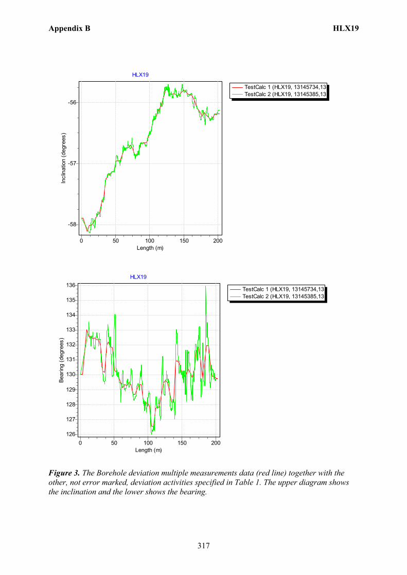
Appendix B HLX19
317
TestCalc 1 (HLX19, 13145734,13TestCalc 2 (HLX19, 13145385,13
HLX19
Length (m)200150100500
Incl
inat
ion
(deg
rees
)
-56
-57
-58
TestCalc 1 (HLX19, 13145734,13TestCalc 2 (HLX19, 13145385,13
HLX19
Length (m)200150100500
Bear
ing
(deg
rees
)
136
135
134
133
132
131
130
129
128
127
126
Figure 3. The Borehole deviation multiple measurements data (red line) together with the other, not error marked, deviation activities specified in Table 1. The upper diagram shows the inclination and the lower shows the bearing.
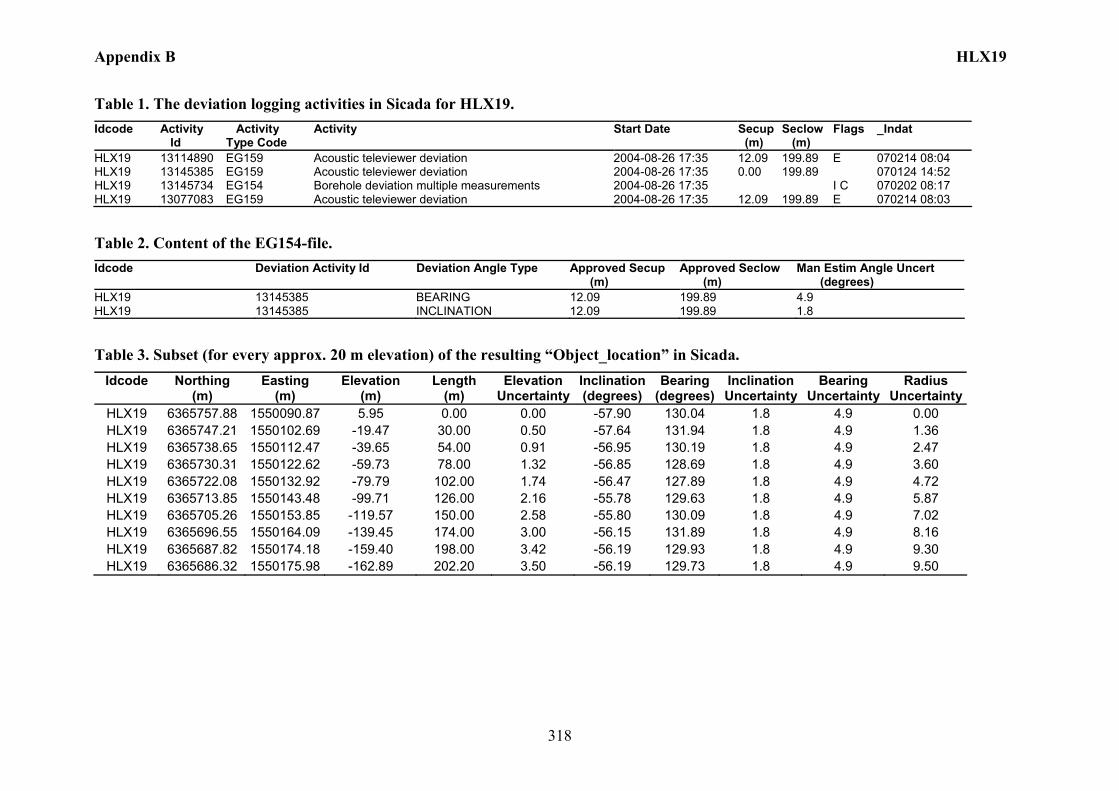
Appendix B HLX19
318
Table 1. The deviation logging activities in Sicada for HLX19. Idcode Activity
Id Activity Type Code
Activity Start Date Secup (m)
Seclow (m)
Flags _Indat
HLX19 13114890 EG159 Acoustic televiewer deviation 2004-08-26 17:35 12.09 199.89 E 070214 08:04 HLX19 13145385 EG159 Acoustic televiewer deviation 2004-08-26 17:35 0.00 199.89 070124 14:52 HLX19 13145734 EG154 Borehole deviation multiple measurements 2004-08-26 17:35 I C 070202 08:17 HLX19 13077083 EG159 Acoustic televiewer deviation 2004-08-26 17:35 12.09 199.89 E 070214 08:03
Table 2. Content of the EG154-file. Idcode Deviation Activity Id Deviation Angle Type Approved Secup
(m) Approved Seclow (m)
Man Estim Angle Uncert (degrees)
HLX19 13145385 BEARING 12.09 199.89 4.9 HLX19 13145385 INCLINATION 12.09 199.89 1.8
Table 3. Subset (for every approx. 20 m elevation) of the resulting “Object_location” in Sicada. Idcode Northing
(m) Easting
(m) Elevation
(m) Length
(m) Elevation
UncertaintyInclination (degrees)
Bearing (degrees)
Inclination Uncertainty
Bearing Uncertainty
Radius Uncertainty
HLX19 6365757.88 1550090.87 5.95 0.00 0.00 -57.90 130.04 1.8 4.9 0.00 HLX19 6365747.21 1550102.69 -19.47 30.00 0.50 -57.64 131.94 1.8 4.9 1.36 HLX19 6365738.65 1550112.47 -39.65 54.00 0.91 -56.95 130.19 1.8 4.9 2.47 HLX19 6365730.31 1550122.62 -59.73 78.00 1.32 -56.85 128.69 1.8 4.9 3.60 HLX19 6365722.08 1550132.92 -79.79 102.00 1.74 -56.47 127.89 1.8 4.9 4.72 HLX19 6365713.85 1550143.48 -99.71 126.00 2.16 -55.78 129.63 1.8 4.9 5.87 HLX19 6365705.26 1550153.85 -119.57 150.00 2.58 -55.80 130.09 1.8 4.9 7.02 HLX19 6365696.55 1550164.09 -139.45 174.00 3.00 -56.15 131.89 1.8 4.9 8.16 HLX19 6365687.82 1550174.18 -159.40 198.00 3.42 -56.19 129.93 1.8 4.9 9.30 HLX19 6365686.32 1550175.98 -162.89 202.20 3.50 -56.19 129.73 1.8 4.9 9.50
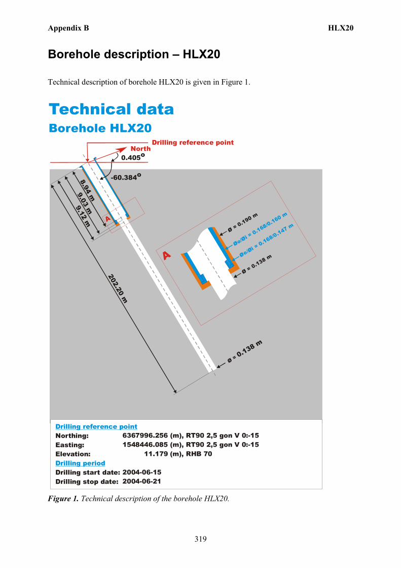
Appendix B HLX20
319
Borehole description – HLX20
Technical description of borehole HLX20 is given in Figure 1.
North
Technical dataBorehole HLX20
6367996.256 (m),(m),
11 (m),
2004-06-152004-06-21
RT90 2,5 gon V 0:-151548446.085 RT90 2,5 gon V 0:-15
.179 RHB 70
-60.384o
Ø = 0.138 m
202.20 m
9.12 m
Øo/Øi = 0.168/0.160 m
Ø = 0.190 m
Ø = 0.138 m
A
A
0.405o
Northing:Easting:Elevation:
Drilling start date:Drilling stop date:
Drilling reference point
Drilling period
Øo/Øi = 0.168/0.147 m
9.03 m8.94 m
Drilling reference point
Figure 1. Technical description of the borehole HLX20.

Appendix B HLX20
320
Borehole direction surveying in HLX20 There is no deviation measurement performed in HLX20. Only the borehole direction surveying was performed from the start of the borehole. Here the starting bearing and inclination is presented in Figure 1. Borehole deviation multiple measurements. In the calculation of Borehole deviation multiple measurements (ID 13149805) the borehole direction surveying (ID 13024938) from start of the borehole was used, Table 1. Table 2 shows the deviation data for the calculation. A subset of the resulting deviation file from Object_location is shown in Table 3. The uncertainty in inclination is calculated according to: –0.000092*(borehole_length)2 + 0.049*borehole length + 1.16 + 1.8. The uncertainty in bearing for boreholes of 100-200 m length is set to 12.4 (= 7.5 + 4.9). The borehole deviation multiple measurement (ID 13146886) was error marked and replaced with (ID 13149805) which was based on the uncertainty calculation above. Figure 2 shows the inclination and bearing of the borehole plotted as a straight line.

Appendix B HLX20
321
TestCalc 1 (HLX20, 13149805,13
HLX20
Length (m)200150100500
Incl
inat
ion
(deg
rees
)
-55
-56
-57
-58
-59
-60
-61
-62
-63
-64
-65
-66
TestCalc 1 (HLX20, 13149805,13
HLX20
Length (m)200150100500
Bear
ing
(deg
rees
)
0,4450,44
0,4350,43
0,4250,42
0,4150,41
0,405
0,40,395
0,390,385
0,380,375
0,370,365
Figure 2. The Borehole deviation multiple measurements data (red line) plotted as a straight line. The upper diagram shows the inclination and the lower shows the bearing.
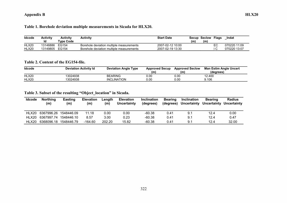
Appendix B HLX20
322
Table 1. Borehole deviation multiple measurements in Sicada for HLX20. Idcode Activity
Id Activity Type Code
Activity Start Date Secup (m)
Seclow (m)
Flags _Indat
HLX20 13146886 EG154 Borehole deviation multiple measurements 2007-02-12 10:00 EC 070220 11:09 HLX20 13149805 EG154 Borehole deviation multiple measurements 2007-02-19 13:30 I C 070220 13:07
Table 2. Content of the EG154-file. Idcode Deviation Activity Id Deviation Angle Type Approved Secup
(m) Approved Seclow (m)
Man Estim Angle Uncert (degrees)
HLX20 13024938 BEARING 0.00 0.00 12.400 HLX20 13024938 INCLINATION 0.00 0.00 9.106
Table 3. Subset of the resulting “Object_location” in Sicada. Idcode Northing
(m) Easting
(m) Elevation
(m) Length
(m) Elevation
Uncertainty Inclination (degrees)
Bearing (degrees)
Inclination Uncertainty
Bearing Uncertainty
Radius Uncertainty
HLX20 6367996.26 1548446.09 11.18 0.00 0.00 -60.38 0.41 9.1 12.4 0.00 HLX20 6367997.74 1548446.10 8.57 3.00 0.23 -60.38 0.41 9.1 12.4 0.47 HLX20 6368096.18 1548446.79 -164.60 202.20 15.82 -60.38 0.41 9.1 12.4 32.00
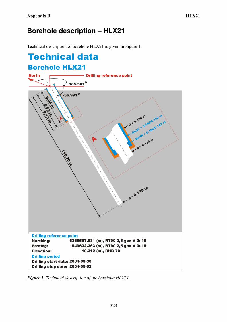
Appendix B HLX21
323
Borehole description – HLX21
Technical description of borehole HLX21 is given in Figure 1.
North
Technical dataBorehole HLX21
6366567.931 (m),(m),
10.312 (m),
2004-08-302004-09-02
RT90 2,5 gon V 0:-151549632.363 RT90 2,5 gon V 0:-15
RHB 70
-56.991o
Ø = 0.138 m
150.30 m
9.10 m
Øo/Øi = 0.168/0.160 m
Ø = 0.190 m
Ø = 0.138 m
A
A
185.541o
Northing:Easting:Elevation:
Drilling start date:Drilling stop date:
Drilling reference point
Drilling period
Øo/Øi = 0.168/0.147 m
9.03 m8.94 m
Drilling reference point
Figure 1. Technical description of the borehole HLX21.

Appendix B HLX21
324
Deviation measurement in HLX21 The only deviation measurement performed in HLX21 was with the acoustic televiewer. On the data a 31 point median filter was used to reduce oscillation in the bearing. The deviation logging activity is tabulated in Sicada Activity Log, see Table 1. The acoustic televiewer measurement (ID 13079479) is executed between borehole lengths 0 – 150.30 m. No geomagnetic disturbance exceeding 0.5 degrees was observed on the date of the acoustic televiewer measurement, see Figure 2.
Figure 2. The geomagnetic field was observed at the Observatory in Uppsala on 2004-10-02.
Borehole deviation multiple measurements. In the calculation of Borehole deviation multiple measurements (ID 13145669) the acoustic televiewer measurement (ID 13079479) was used. Table 2 shows the deviation data for the calculation. A subset of the resulting deviation file for every approximately 20 m elevation (from Object_location) is shown in Table 3. When only one measurement is used the standard values of inclination uncertainty, 1.8 and bearing uncertainty of 4.9 is used for calculation of the radius uncertainty for every measuring level. Figure 3 show the resulting deviation data together with the other deviation activity listed in Table 1.
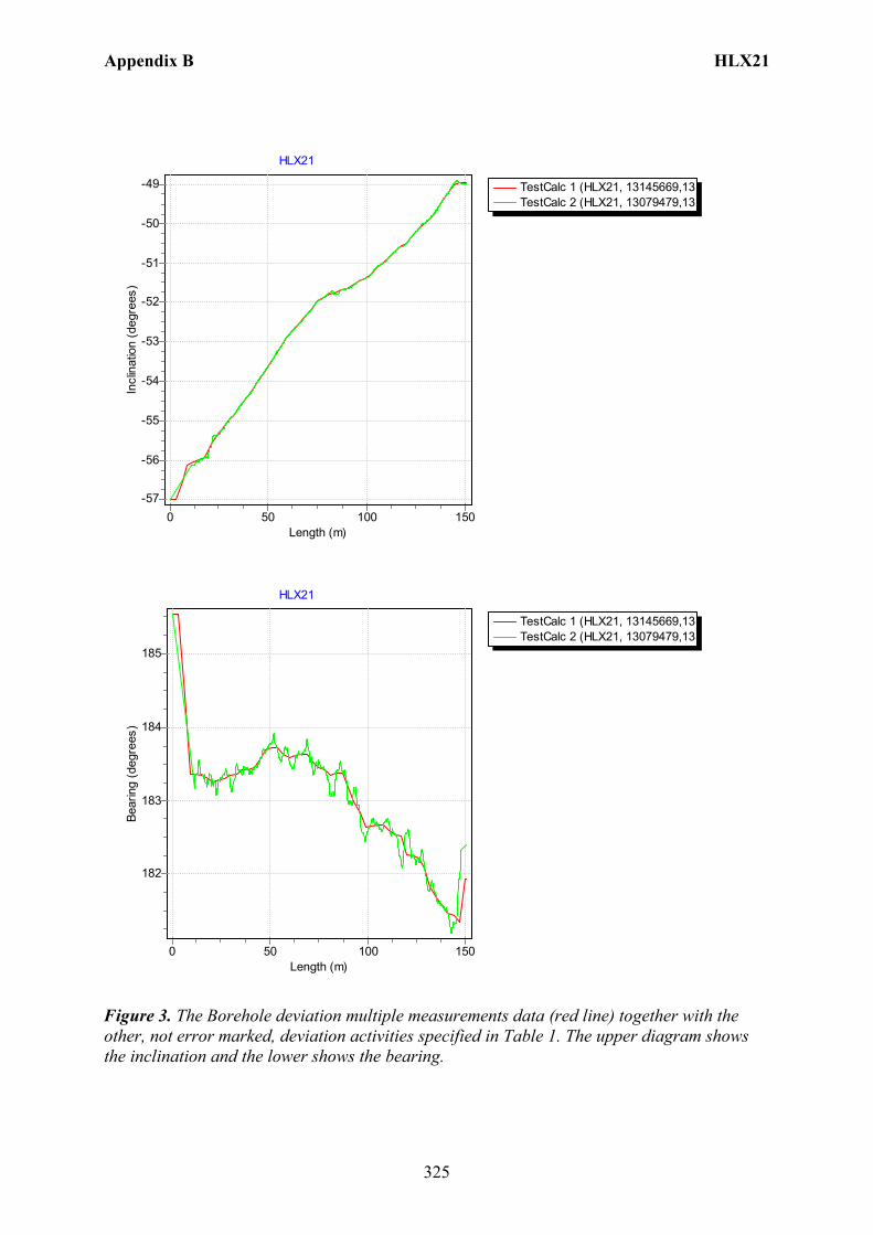
Appendix B HLX21
325
TestCalc 1 (HLX21, 13145669,13TestCalc 2 (HLX21, 13079479,13
HLX21
Length (m)150100500
Incl
inat
ion
(deg
rees
)
-49
-50
-51
-52
-53
-54
-55
-56
-57
TestCalc 1 (HLX21, 13145669,13TestCalc 2 (HLX21, 13079479,13
HLX21
Length (m)150100500
Bear
ing
(deg
rees
)
185
184
183
182
Figure 3. The Borehole deviation multiple measurements data (red line) together with the other, not error marked, deviation activities specified in Table 1. The upper diagram shows the inclination and the lower shows the bearing.
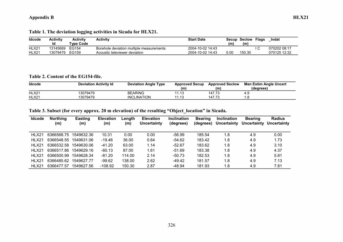
Appendix B HLX21
326
Table 1. The deviation logging activities in Sicada for HLX21. Idcode Activity
Id Activity Type Code
Activity Start Date Secup (m)
Seclow (m)
Flags _Indat
HLX21 13145669 EG154 Borehole deviation multiple measurements 2004-10-02 14:43 I C 070202 08:17 HLX21 13079479 EG159 Acoustic televiewer deviation 2004-10-02 14:43 0.00 150.30 070125 12:32
Table 2. Content of the EG154-file. Idcode Deviation Activity Id Deviation Angle Type Approved Secup
(m) Approved Seclow (m)
Man Estim Angle Uncert (degrees)
HLX21 13079479 BEARING 11.13 147.73 4.9 HLX21 13079479 INCLINATION 11.13 147.73 1.8
Table 3. Subset (for every approx. 20 m elevation) of the resulting “Object_location” in Sicada. Idcode Northing
(m) Easting
(m) Elevation
(m) Length
(m) Elevation
Uncertainty Inclination (degrees)
Bearing (degrees)
Inclination Uncertainty
Bearing Uncertainty
Radius Uncertainty
HLX21 6366568.75 1549632.36 10.31 0.00 0.00 -56.99 185.54 1.8 4.9 0.00 HLX21 6366548.55 1549631.06 -19.46 36.00 0.64 -54.62 183.42 1.8 4.9 1.73 HLX21 6366532.58 1549630.06 -41.20 63.00 1.14 -52.67 183.62 1.8 4.9 3.10 HLX21 6366517.86 1549629.16 -60.13 87.00 1.61 -51.69 183.38 1.8 4.9 4.37 HLX21 6366500.99 1549628.34 -81.20 114.00 2.14 -50.73 182.53 1.8 4.9 5.81 HLX21 6366485.62 1549627.77 -99.62 138.00 2.62 -49.42 181.57 1.8 4.9 7.13 HLX21 6366477.57 1549627.56 -108.92 150.30 2.87 -48.94 181.93 1.8 4.9 7.81
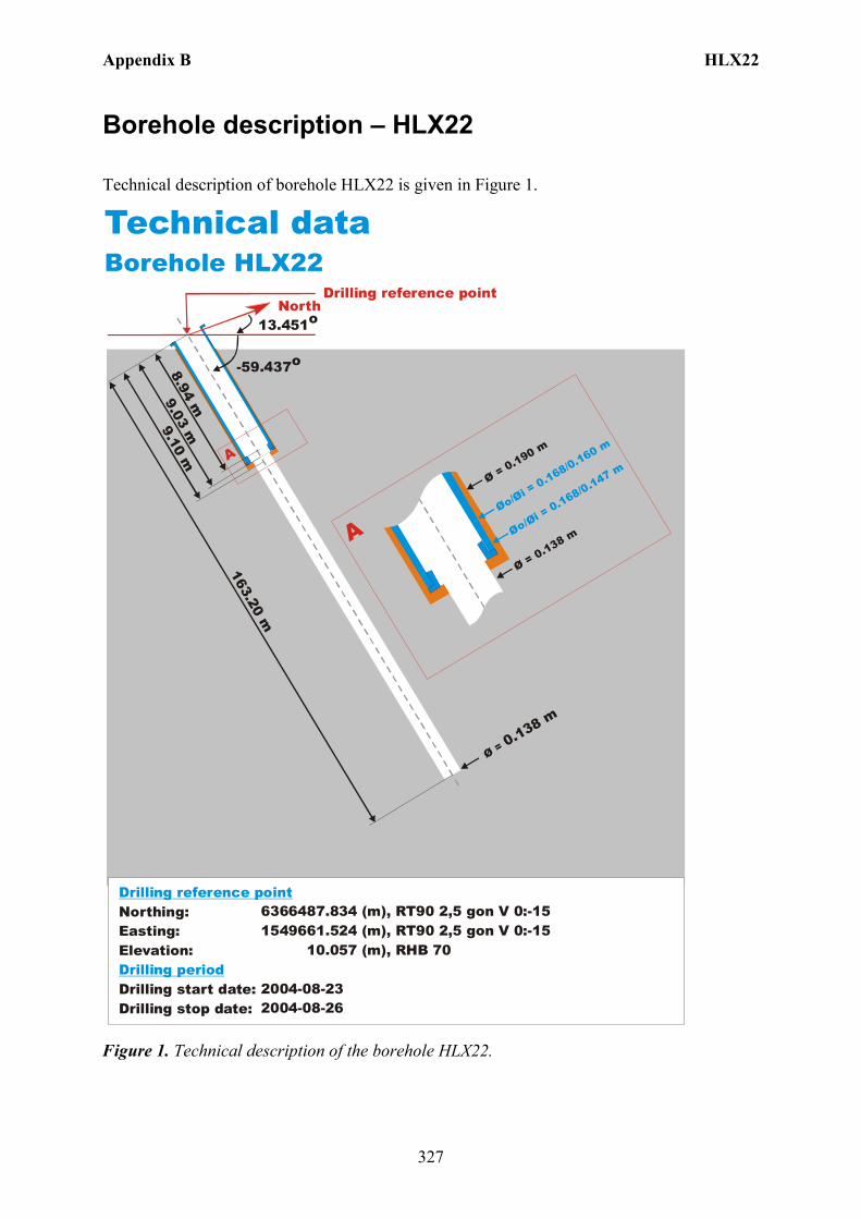
Appendix B HLX22
327
Borehole description – HLX22
Technical description of borehole HLX22 is given in Figure 1.
North
Technical dataBorehole HLX22
6366487.834 (m),(m),
10.057 (m),
2004-08-232004-08-26
RT90 2,5 gon V 0:-151549661.524 RT90 2,5 gon V 0:-15
RHB 70
-59.437o
Ø = 0.138 m
163.20 m
9.10 m
Øo/Øi = 0.168/0.160 m
Ø = 0.190 m
Ø = 0.138 m
A
A
13.451o
Northing:Easting:Elevation:
Drilling start date:Drilling stop date:
Drilling reference point
Drilling period
Øo/Øi = 0.168/0.147 m
9.03 m8.94 m
Drilling reference point
Figure 1. Technical description of the borehole HLX22.

Appendix B HLX22
328
Deviation measurement in HLX22 The only deviation measurement performed in HLX22 was with the acoustic televiewer. On the data a 31 point median filter was used to reduce oscillation in the bearing. The deviation logging activity is tabulated in Sicada Activity Log, see Table 1. The acoustic televiewer measurement (ID 13079480) is executed between borehole lengths 0 – 163.20 m. No geomagnetic disturbance exceeding 0.5 degrees was observed on the date of the acoustic televiewer measurement, see Figure 2.
Figure 2. The geomagnetic field was observed at the Observatory in Uppsala on 2004-10-02.
Borehole deviation multiple measurements. In the calculation of Borehole deviation multiple measurements (ID 13145670) the acoustic televiewer measurement (ID 13079480) was used. Table 2 shows the deviation data for the calculation. A subset of the resulting deviation file for every approximately 20 m elevation (from Object_location) is shown in Table 3. When only one measurement is used the standard values of inclination uncertainty, 1.8 and bearing uncertainty of 4.9 is used for calculation of the radius uncertainty for every measuring level. Figure 3 show the resulting deviation data together with the other deviation activity listed in Table 1.
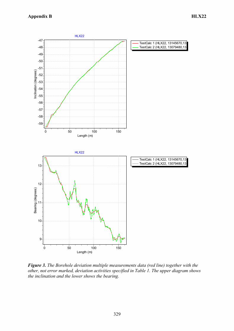
Appendix B HLX22
329
TestCalc 1 (HLX22, 13145670,13TestCalc 2 (HLX22, 13079480,13
HLX22
Length (m)150100500
Incl
inat
ion
(deg
rees
)
-47
-48
-49
-50
-51
-52
-53
-54
-55
-56
-57
-58
-59
TestCalc 1 (HLX22, 13145670,13TestCalc 2 (HLX22, 13079480,13
HLX22
Length (m)150100500
Bear
ing
(deg
rees
)
13
12
11
10
9
Figure 3. The Borehole deviation multiple measurements data (red line) together with the other, not error marked, deviation activities specified in Table 1. The upper diagram shows the inclination and the lower shows the bearing.
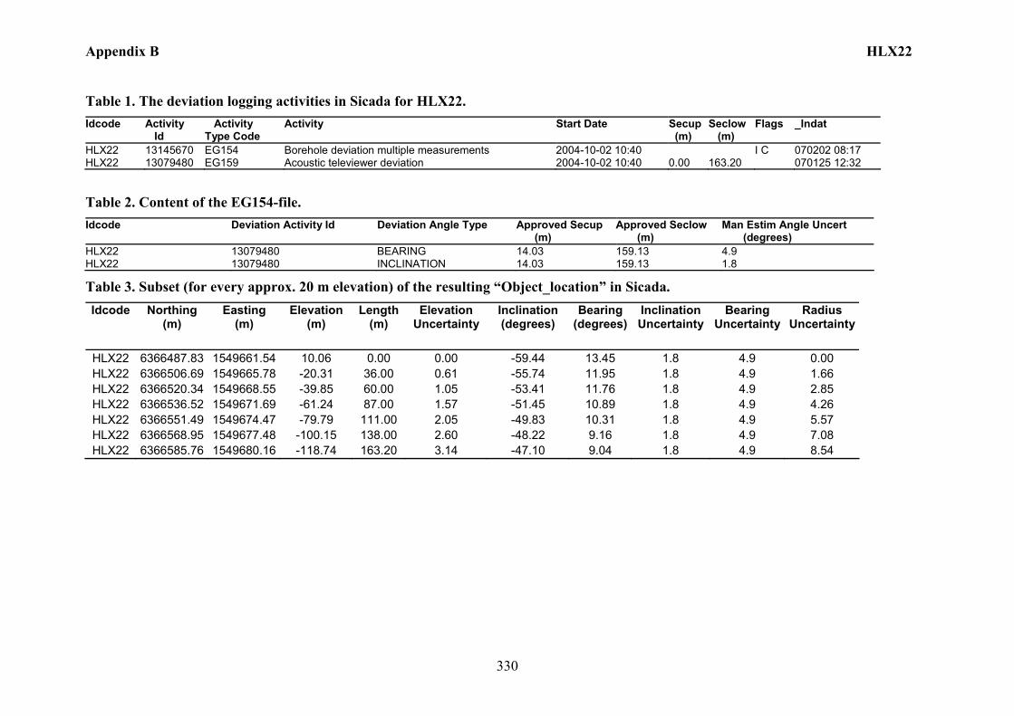
Appendix B HLX22
330
Table 1. The deviation logging activities in Sicada for HLX22. Idcode Activity
Id Activity Type Code
Activity Start Date Secup (m)
Seclow (m)
Flags _Indat
HLX22 13145670 EG154 Borehole deviation multiple measurements 2004-10-02 10:40 I C 070202 08:17 HLX22 13079480 EG159 Acoustic televiewer deviation 2004-10-02 10:40 0.00 163.20 070125 12:32
Table 2. Content of the EG154-file. Idcode Deviation Activity Id Deviation Angle Type Approved Secup
(m) Approved Seclow (m)
Man Estim Angle Uncert (degrees)
HLX22 13079480 BEARING 14.03 159.13 4.9 HLX22 13079480 INCLINATION 14.03 159.13 1.8
Table 3. Subset (for every approx. 20 m elevation) of the resulting “Object_location” in Sicada. Idcode Northing
(m) Easting
(m) Elevation
(m) Length
(m) Elevation
Uncertainty Inclination (degrees)
Bearing (degrees)
Inclination Uncertainty
Bearing Uncertainty
Radius Uncertainty
HLX22 6366487.83 1549661.54 10.06 0.00 0.00 -59.44 13.45 1.8 4.9 0.00 HLX22 6366506.69 1549665.78 -20.31 36.00 0.61 -55.74 11.95 1.8 4.9 1.66 HLX22 6366520.34 1549668.55 -39.85 60.00 1.05 -53.41 11.76 1.8 4.9 2.85 HLX22 6366536.52 1549671.69 -61.24 87.00 1.57 -51.45 10.89 1.8 4.9 4.26 HLX22 6366551.49 1549674.47 -79.79 111.00 2.05 -49.83 10.31 1.8 4.9 5.57 HLX22 6366568.95 1549677.48 -100.15 138.00 2.60 -48.22 9.16 1.8 4.9 7.08 HLX22 6366585.76 1549680.16 -118.74 163.20 3.14 -47.10 9.04 1.8 4.9 8.54
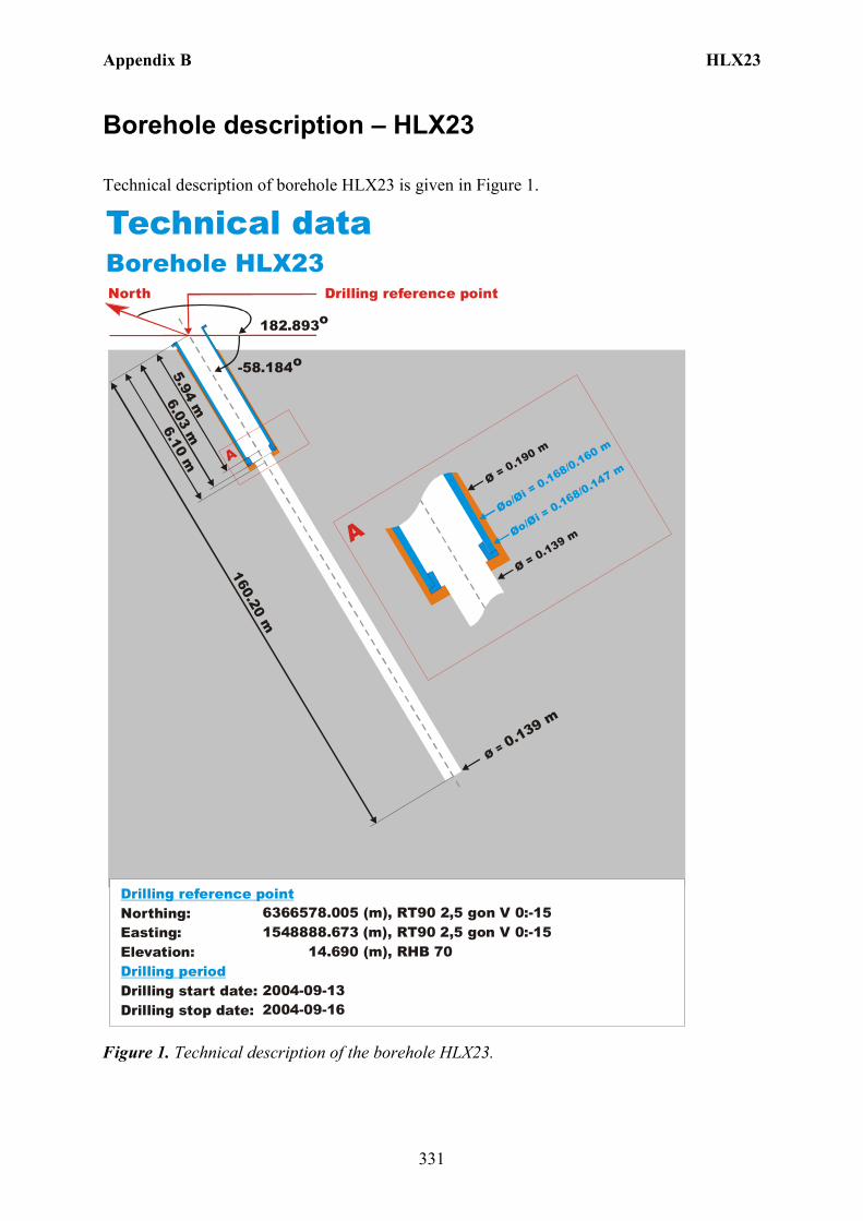
Appendix B HLX23
331
Borehole description – HLX23
Technical description of borehole HLX23 is given in Figure 1.
North
Technical dataBorehole HLX23
6366578.005 (m),(m),
14.690 (m),
2004-09-132004-09-16
RT90 2,5 gon V 0:-151548888.673 RT90 2,5 gon V 0:-15
RHB 70
-58.184o
Ø = 0.139 m
160.20 m
6.10 m
Øo/Øi = 0.168/0.160 m
Ø = 0.190 m
Ø = 0.139 m
A
A
182.893o
Northing:Easting:Elevation:
Drilling start date:Drilling stop date:
Drilling reference point
Drilling period
Øo/Øi = 0.168/0.147 m
6.03 m5.94 m
Drilling reference point
Figure 1. Technical description of the borehole HLX23.

Appendix B HLX23
332
Deviation measurement in HLX23 The only deviation measurement performed in HLX23 was with the acoustic televiewer. On the data a 31 point median filter was used to reduce oscillation in the bearing. The deviation logging activity is tabulated in Sicada Activity Log, see Table 1. The acoustic televiewer measurement (ID 13079483) is executed between borehole lengths 0 – 160.20 m. No geomagnetic disturbance exceeding 0.5 degrees was observed on the date of the acoustic televiewer measurement, see Figure 2.
Figure 2. The geomagnetic field was observed at the Observatory in Uppsala on 2004-10-02.
Borehole deviation multiple measurements. In the calculation of Borehole deviation multiple measurements (ID 13145671) the acoustic televiewer measurement (ID 13079483) was used. Table 2 shows the deviation data for the calculation. A subset of the resulting deviation file for every approximately 20 m elevation (from Object_location) is shown in Table 3. When only one measurement is used the standard values of inclination uncertainty, 1.8 and bearing uncertainty of 4.9 is used for calculation of the radius uncertainty for every measuring level. Figure 3 show the resulting deviation data together with the other deviation activity listed in Table 1.
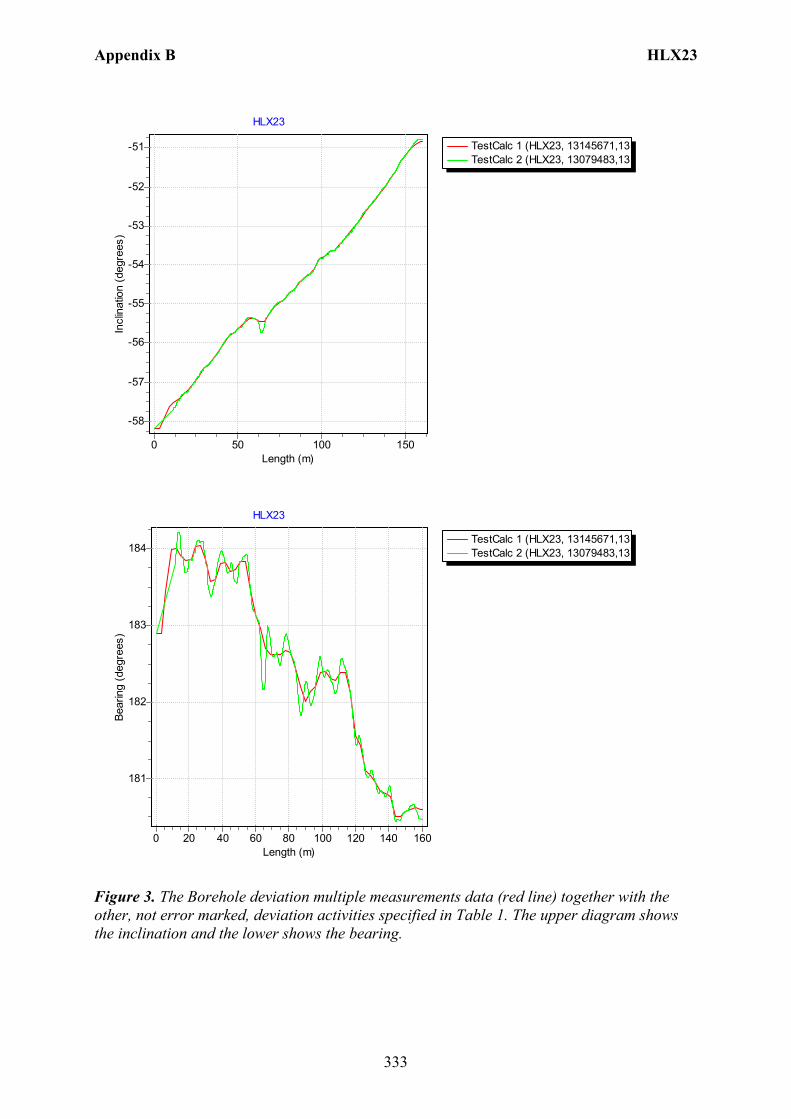
Appendix B HLX23
333
TestCalc 1 (HLX23, 13145671,13TestCalc 2 (HLX23, 13079483,13
HLX23
Length (m)150100500
Incl
inat
ion
(deg
rees
)
-51
-52
-53
-54
-55
-56
-57
-58
TestCalc 1 (HLX23, 13145671,13TestCalc 2 (HLX23, 13079483,13
HLX23
Length (m)160140120100806040200
Bear
ing
(deg
rees
)
184
183
182
181
Figure 3. The Borehole deviation multiple measurements data (red line) together with the other, not error marked, deviation activities specified in Table 1. The upper diagram shows the inclination and the lower shows the bearing.
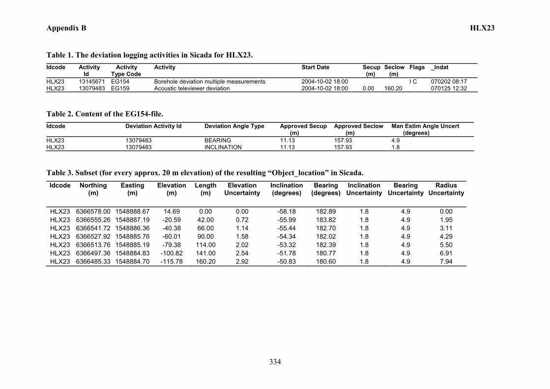
Appendix B HLX23
334
Table 1. The deviation logging activities in Sicada for HLX23. Idcode Activity
Id Activity Type Code
Activity Start Date Secup (m)
Seclow (m)
Flags _Indat
HLX23 13145671 EG154 Borehole deviation multiple measurements 2004-10-02 18:00 I C 070202 08:17 HLX23 13079483 EG159 Acoustic televiewer deviation 2004-10-02 18:00 0.00 160.20 070125 12:32
Table 2. Content of the EG154-file. Idcode Deviation Activity Id Deviation Angle Type Approved Secup
(m) Approved Seclow (m)
Man Estim Angle Uncert (degrees)
HLX23 13079483 BEARING 11.13 157.93 4.9 HLX23 13079483 INCLINATION 11.13 157.93 1.8
Table 3. Subset (for every approx. 20 m elevation) of the resulting “Object_location” in Sicada. Idcode Northing
(m) Easting
(m) Elevation
(m) Length
(m) Elevation
Uncertainty Inclination (degrees)
Bearing (degrees)
Inclination Uncertainty
Bearing Uncertainty
Radius Uncertainty
HLX23 6366578.00 1548888.67 14.69 0.00 0.00 -58.18 182.89 1.8 4.9 0.00 HLX23 6366555.26 1548887.19 -20.59 42.00 0.72 -55.99 183.82 1.8 4.9 1.95 HLX23 6366541.72 1548886.36 -40.38 66.00 1.14 -55.44 182.70 1.8 4.9 3.11 HLX23 6366527.92 1548885.76 -60.01 90.00 1.58 -54.34 182.02 1.8 4.9 4.29 HLX23 6366513.76 1548885.19 -79.38 114.00 2.02 -53.32 182.39 1.8 4.9 5.50 HLX23 6366497.36 1548884.83 -100.82 141.00 2.54 -51.78 180.77 1.8 4.9 6.91 HLX23 6366485.33 1548884.70 -115.78 160.20 2.92 -50.83 180.60 1.8 4.9 7.94
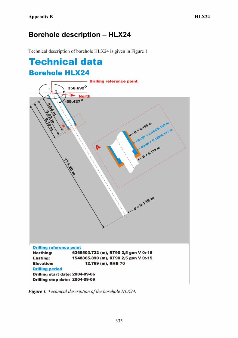
Appendix B HLX24
335
Borehole description – HLX24
Technical description of borehole HLX24 is given in Figure 1.
North
Technical dataBorehole HLX24
6366503.722 (m),(m),
12.769 (m),
2004-09-062004-09-09
RT90 2,5 gon V 0:-151548865.890 RT90 2,5 gon V 0:-15
RHB 70
-59.437o
Ø = 0.139 m
175.20 m
9.10 m
Øo/Øi = 0.168/0.160 m
Ø = 0.190 m
Ø = 0.139 m
A
A
358.692o
Northing:Easting:Elevation:
Drilling start date:Drilling stop date:
Drilling reference point
Drilling period
Øo/Øi = 0.168/0.147 m
9.03 m8.94 m
Drilling reference point
Figure 1. Technical description of the borehole HLX24.
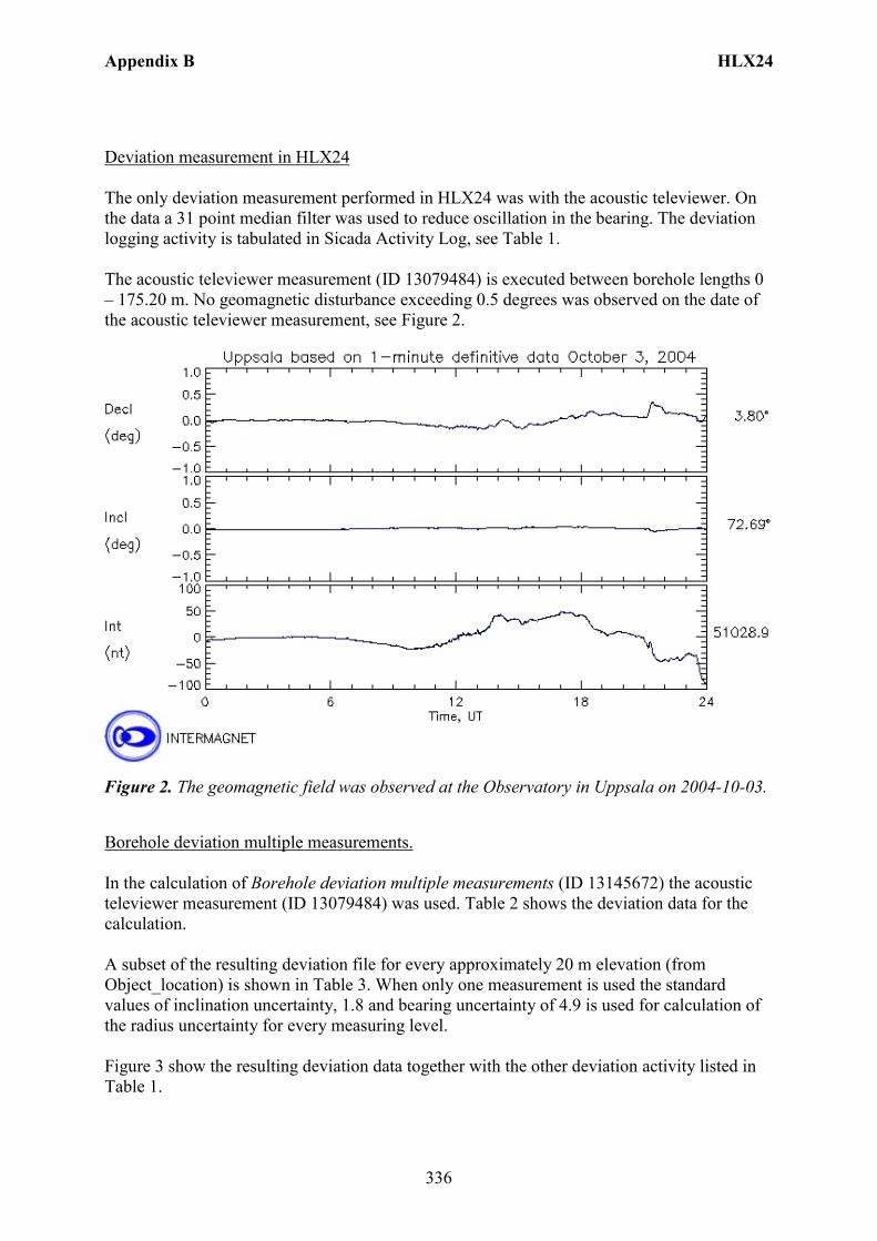
Appendix B HLX24
336
Deviation measurement in HLX24 The only deviation measurement performed in HLX24 was with the acoustic televiewer. On the data a 31 point median filter was used to reduce oscillation in the bearing. The deviation logging activity is tabulated in Sicada Activity Log, see Table 1. The acoustic televiewer measurement (ID 13079484) is executed between borehole lengths 0 – 175.20 m. No geomagnetic disturbance exceeding 0.5 degrees was observed on the date of the acoustic televiewer measurement, see Figure 2.
Figure 2. The geomagnetic field was observed at the Observatory in Uppsala on 2004-10-03.
Borehole deviation multiple measurements. In the calculation of Borehole deviation multiple measurements (ID 13145672) the acoustic televiewer measurement (ID 13079484) was used. Table 2 shows the deviation data for the calculation. A subset of the resulting deviation file for every approximately 20 m elevation (from Object_location) is shown in Table 3. When only one measurement is used the standard values of inclination uncertainty, 1.8 and bearing uncertainty of 4.9 is used for calculation of the radius uncertainty for every measuring level. Figure 3 show the resulting deviation data together with the other deviation activity listed in Table 1.
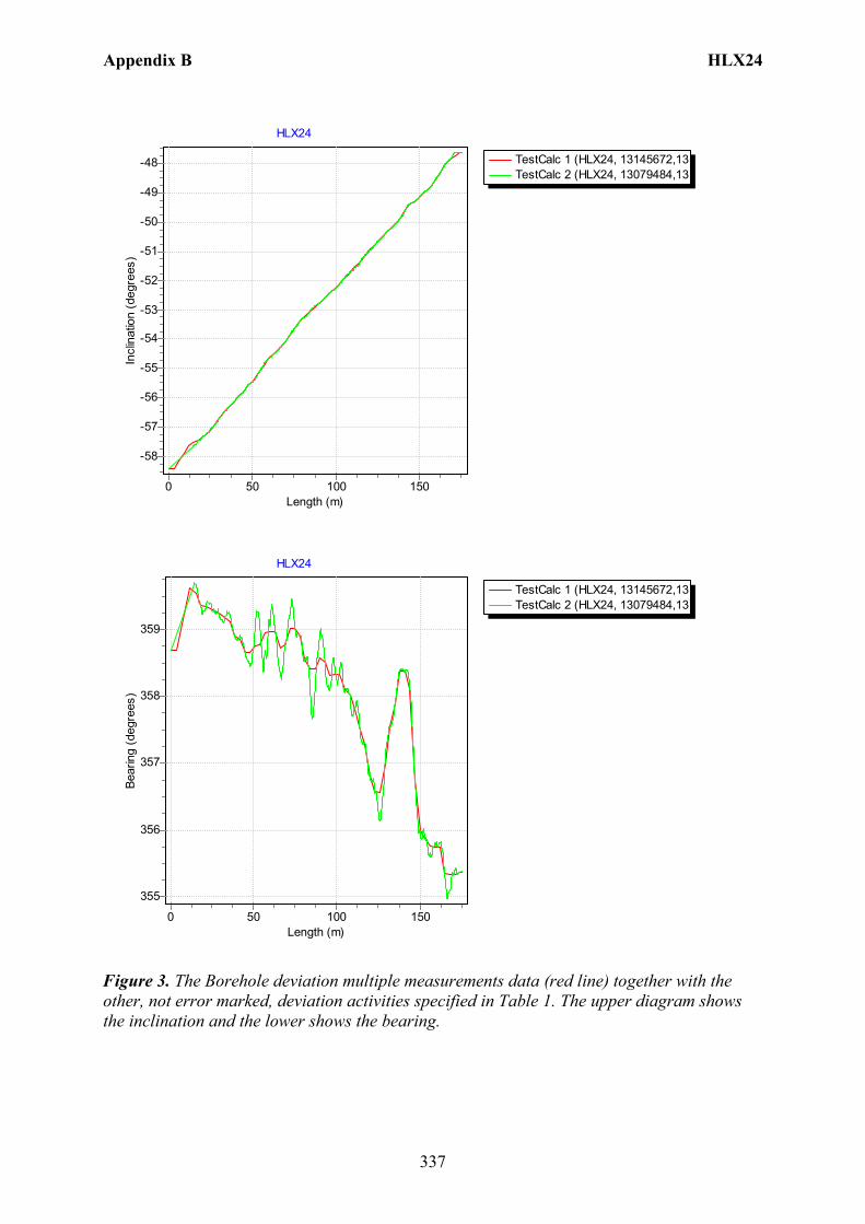
Appendix B HLX24
337
TestCalc 1 (HLX24, 13145672,13TestCalc 2 (HLX24, 13079484,13
HLX24
Length (m)150100500
Incl
inat
ion
(deg
rees
)
-48
-49
-50
-51
-52
-53
-54
-55
-56
-57
-58
TestCalc 1 (HLX24, 13145672,13TestCalc 2 (HLX24, 13079484,13
HLX24
Length (m)150100500
Bear
ing
(deg
rees
)
359
358
357
356
355
Figure 3. The Borehole deviation multiple measurements data (red line) together with the other, not error marked, deviation activities specified in Table 1. The upper diagram shows the inclination and the lower shows the bearing.
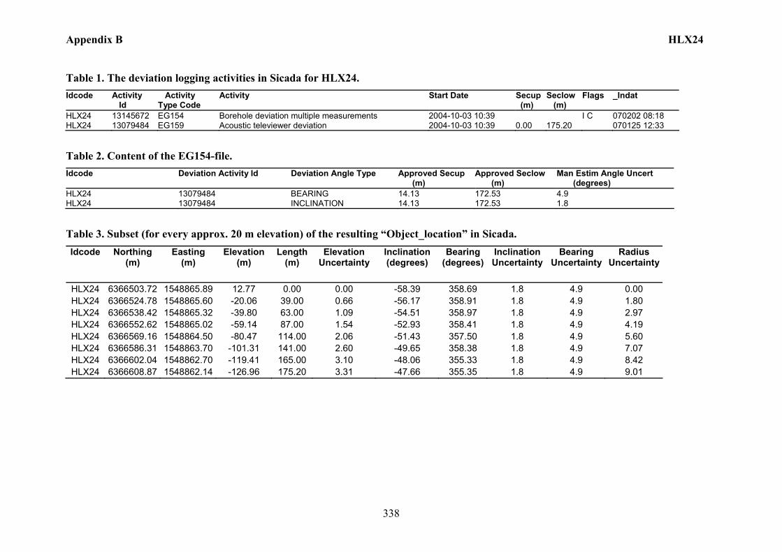
Appendix B HLX24
338
Table 1. The deviation logging activities in Sicada for HLX24. Idcode Activity
Id Activity Type Code
Activity Start Date Secup (m)
Seclow (m)
Flags _Indat
HLX24 13145672 EG154 Borehole deviation multiple measurements 2004-10-03 10:39 I C 070202 08:18 HLX24 13079484 EG159 Acoustic televiewer deviation 2004-10-03 10:39 0.00 175.20 070125 12:33
Table 2. Content of the EG154-file. Idcode Deviation Activity Id Deviation Angle Type Approved Secup
(m) Approved Seclow (m)
Man Estim Angle Uncert (degrees)
HLX24 13079484 BEARING 14.13 172.53 4.9 HLX24 13079484 INCLINATION 14.13 172.53 1.8
Table 3. Subset (for every approx. 20 m elevation) of the resulting “Object_location” in Sicada. Idcode Northing
(m) Easting
(m) Elevation
(m) Length
(m) Elevation
Uncertainty Inclination (degrees)
Bearing (degrees)
Inclination Uncertainty
Bearing Uncertainty
Radius Uncertainty
HLX24 6366503.72 1548865.89 12.77 0.00 0.00 -58.39 358.69 1.8 4.9 0.00 HLX24 6366524.78 1548865.60 -20.06 39.00 0.66 -56.17 358.91 1.8 4.9 1.80 HLX24 6366538.42 1548865.32 -39.80 63.00 1.09 -54.51 358.97 1.8 4.9 2.97 HLX24 6366552.62 1548865.02 -59.14 87.00 1.54 -52.93 358.41 1.8 4.9 4.19 HLX24 6366569.16 1548864.50 -80.47 114.00 2.06 -51.43 357.50 1.8 4.9 5.60 HLX24 6366586.31 1548863.70 -101.31 141.00 2.60 -49.65 358.38 1.8 4.9 7.07 HLX24 6366602.04 1548862.70 -119.41 165.00 3.10 -48.06 355.33 1.8 4.9 8.42 HLX24 6366608.87 1548862.14 -126.96 175.20 3.31 -47.66 355.35 1.8 4.9 9.01
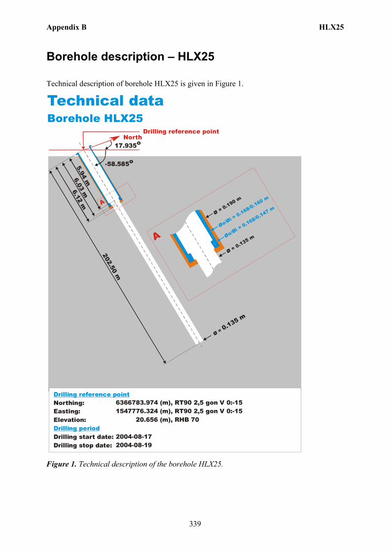
Appendix B HLX25
339
Borehole description – HLX25
Technical description of borehole HLX25 is given in Figure 1.
North
Technical dataBorehole HLX25
6366783.974 (m),(m),
20.656 (m),
2004-08-172004-08-19
RT90 2,5 gon V 0:-151547776.324 RT90 2,5 gon V 0:-15
RHB 70
-58.585o
Ø = 0.135 m
202.50 m
6.12 m
Øo/Øi = 0.168/0.160 m
Ø = 0.190 m
Ø = 0.135 m
A
A
17.935o
Northing:Easting:Elevation:
Drilling start date:Drilling stop date:
Drilling reference point
Drilling period
Øo/Øi = 0.168/0.147 m
6.03 m5.94 m
Drilling reference point
Figure 1. Technical description of the borehole HLX25.
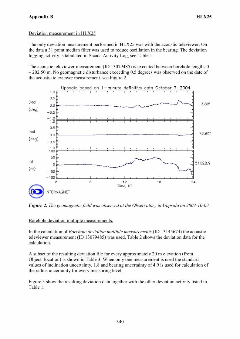
Appendix B HLX25
340
Deviation measurement in HLX25 The only deviation measurement performed in HLX25 was with the acoustic televiewer. On the data a 31 point median filter was used to reduce oscillation in the bearing. The deviation logging activity is tabulated in Sicada Activity Log, see Table 1. The acoustic televiewer measurement (ID 13079485) is executed between borehole lengths 0 – 202.50 m. No geomagnetic disturbance exceeding 0.5 degrees was observed on the date of the acoustic televiewer measurement, see Figure 2.
Figure 2. The geomagnetic field was observed at the Observatory in Uppsala on 2004-10-03.
Borehole deviation multiple measurements. In the calculation of Borehole deviation multiple measurements (ID 13145674) the acoustic televiewer measurement (ID 13079485) was used. Table 2 shows the deviation data for the calculation. A subset of the resulting deviation file for every approximately 20 m elevation (from Object_location) is shown in Table 3. When only one measurement is used the standard values of inclination uncertainty, 1.8 and bearing uncertainty of 4.9 is used for calculation of the radius uncertainty for every measuring level. Figure 3 show the resulting deviation data together with the other deviation activity listed in Table 1.
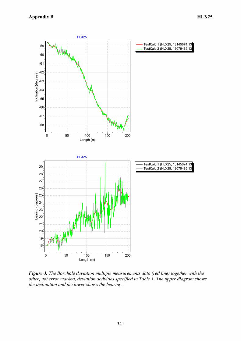
Appendix B HLX25
341
TestCalc 1 (HLX25, 13145674,13TestCalc 2 (HLX25, 13079485,13
HLX25
Length (m)200150100500
Incl
inat
ion
(deg
rees
)
-59
-60
-61
-62
-63
-64
-65
-66
-67
-68
TestCalc 1 (HLX25, 13145674,13TestCalc 2 (HLX25, 13079485,13
HLX25
Length (m)200150100500
Bear
ing
(deg
rees
)
29
28
27
26
25
24
23
22
21
20
19
18
Figure 3. The Borehole deviation multiple measurements data (red line) together with the other, not error marked, deviation activities specified in Table 1. The upper diagram shows the inclination and the lower shows the bearing.
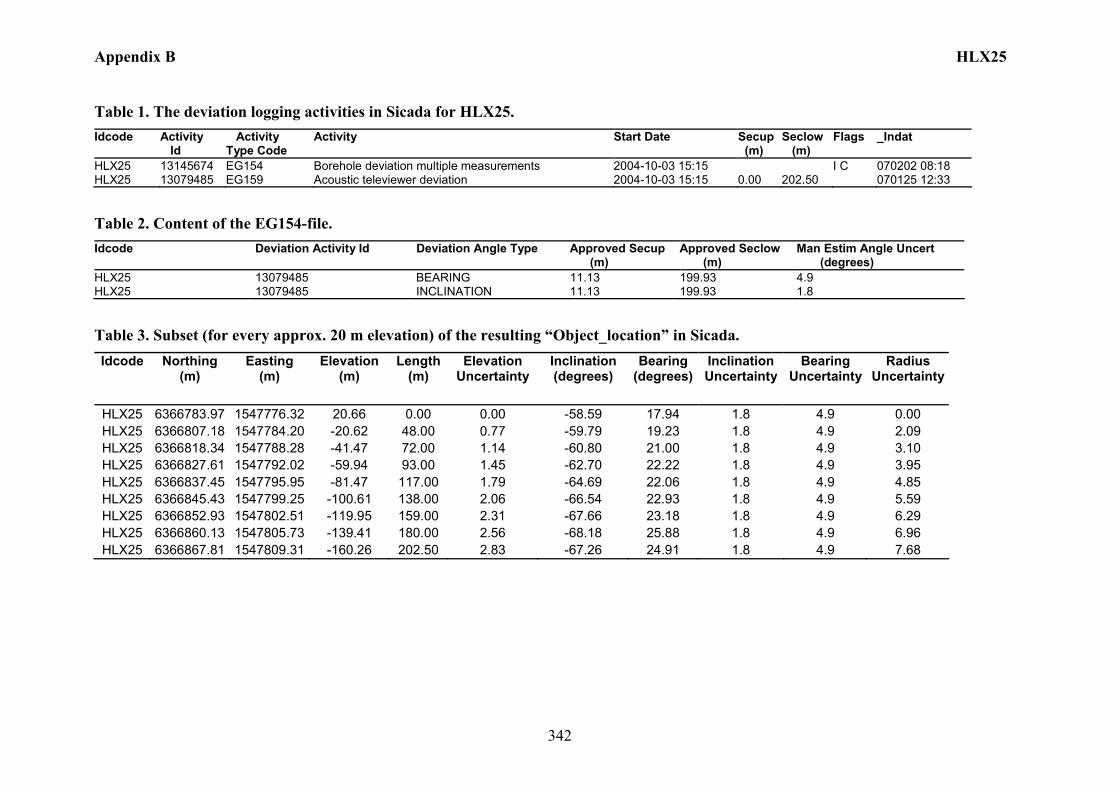
Appendix B HLX25
342
Table 1. The deviation logging activities in Sicada for HLX25. Idcode Activity
Id Activity Type Code
Activity Start Date Secup (m)
Seclow (m)
Flags _Indat
HLX25 13145674 EG154 Borehole deviation multiple measurements 2004-10-03 15:15 I C 070202 08:18 HLX25 13079485 EG159 Acoustic televiewer deviation 2004-10-03 15:15 0.00 202.50 070125 12:33
Table 2. Content of the EG154-file. Idcode Deviation Activity Id Deviation Angle Type Approved Secup
(m) Approved Seclow (m)
Man Estim Angle Uncert (degrees)
HLX25 13079485 BEARING 11.13 199.93 4.9 HLX25 13079485 INCLINATION 11.13 199.93 1.8
Table 3. Subset (for every approx. 20 m elevation) of the resulting “Object_location” in Sicada. Idcode Northing
(m) Easting
(m) Elevation
(m) Length
(m) Elevation
Uncertainty Inclination (degrees)
Bearing (degrees)
Inclination Uncertainty
Bearing Uncertainty
Radius Uncertainty
HLX25 6366783.97 1547776.32 20.66 0.00 0.00 -58.59 17.94 1.8 4.9 0.00 HLX25 6366807.18 1547784.20 -20.62 48.00 0.77 -59.79 19.23 1.8 4.9 2.09 HLX25 6366818.34 1547788.28 -41.47 72.00 1.14 -60.80 21.00 1.8 4.9 3.10 HLX25 6366827.61 1547792.02 -59.94 93.00 1.45 -62.70 22.22 1.8 4.9 3.95 HLX25 6366837.45 1547795.95 -81.47 117.00 1.79 -64.69 22.06 1.8 4.9 4.85 HLX25 6366845.43 1547799.25 -100.61 138.00 2.06 -66.54 22.93 1.8 4.9 5.59 HLX25 6366852.93 1547802.51 -119.95 159.00 2.31 -67.66 23.18 1.8 4.9 6.29 HLX25 6366860.13 1547805.73 -139.41 180.00 2.56 -68.18 25.88 1.8 4.9 6.96 HLX25 6366867.81 1547809.31 -160.26 202.50 2.83 -67.26 24.91 1.8 4.9 7.68
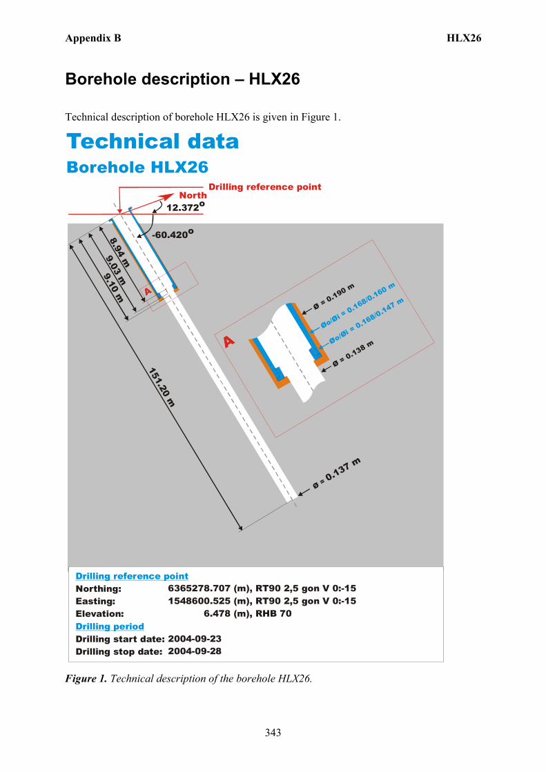
Appendix B HLX26
343
Borehole description – HLX26
Technical description of borehole HLX26 is given in Figure 1.
North
Technical dataBorehole HLX26
6365278.707 (m),(m),
6.478 (m),
2004-09-232004-09-28
RT90 2,5 gon V 0:-151548600.525 RT90 2,5 gon V 0:-15
RHB 70
-60.420o
Ø = 0.137 m
151.20 m
9.10 m
Øo/Øi = 0.168/0.160 m
Ø = 0.190 m
Ø = 0.138 m
A
A
12.372o
Northing:Easting:Elevation:
Drilling start date:Drilling stop date:
Drilling reference point
Drilling period
Øo/Øi = 0.168/0.147 m
9.03 m8.94 m
Drilling reference point
Figure 1. Technical description of the borehole HLX26.
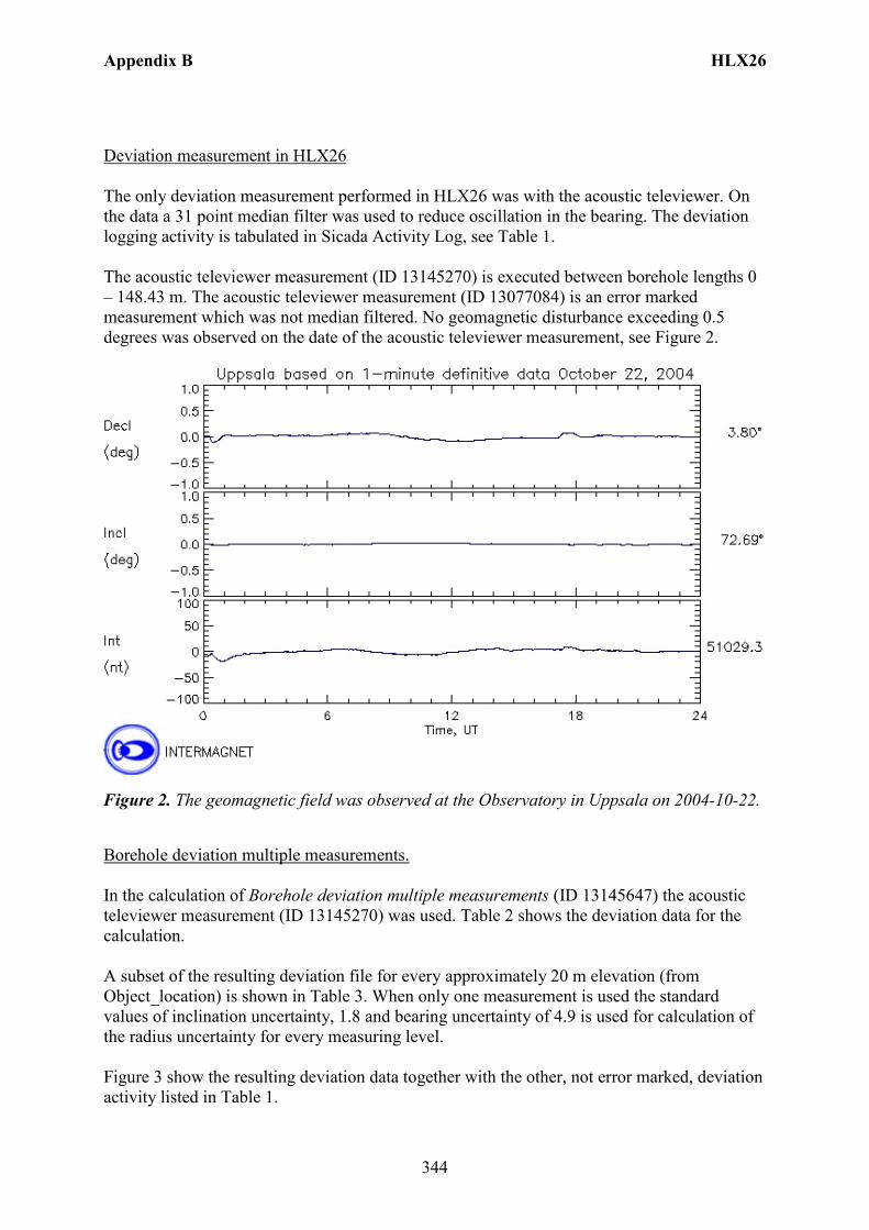
Appendix B HLX26
344
Deviation measurement in HLX26 The only deviation measurement performed in HLX26 was with the acoustic televiewer. On the data a 31 point median filter was used to reduce oscillation in the bearing. The deviation logging activity is tabulated in Sicada Activity Log, see Table 1. The acoustic televiewer measurement (ID 13145270) is executed between borehole lengths 0 – 148.43 m. The acoustic televiewer measurement (ID 13077084) is an error marked measurement which was not median filtered. No geomagnetic disturbance exceeding 0.5 degrees was observed on the date of the acoustic televiewer measurement, see Figure 2.
Figure 2. The geomagnetic field was observed at the Observatory in Uppsala on 2004-10-22.
Borehole deviation multiple measurements. In the calculation of Borehole deviation multiple measurements (ID 13145647) the acoustic televiewer measurement (ID 13145270) was used. Table 2 shows the deviation data for the calculation. A subset of the resulting deviation file for every approximately 20 m elevation (from Object_location) is shown in Table 3. When only one measurement is used the standard values of inclination uncertainty, 1.8 and bearing uncertainty of 4.9 is used for calculation of the radius uncertainty for every measuring level. Figure 3 show the resulting deviation data together with the other, not error marked, deviation activity listed in Table 1.
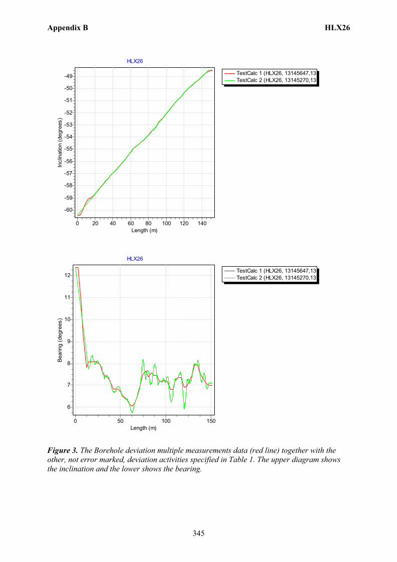
Appendix B HLX26
345
TestCalc 1 (HLX26, 13145647,13TestCalc 2 (HLX26, 13145270,13
HLX26
Length (m)140120100806040200
Incl
inat
ion
(deg
rees
)
-49
-50
-51
-52
-53
-54
-55
-56
-57
-58
-59
-60
TestCalc 1 (HLX26, 13145647,13TestCalc 2 (HLX26, 13145270,13
HLX26
Length (m)150100500
Bear
ing
(deg
rees
)
12
11
10
9
8
7
6
Figure 3. The Borehole deviation multiple measurements data (red line) together with the other, not error marked, deviation activities specified in Table 1. The upper diagram shows the inclination and the lower shows the bearing.

Appendix B HLX26
346
Table 1. The deviation logging activities in Sicada for HLX26. Idcode Activity
Id Activity Type Code
Activity Start Date Secup (m)
Seclow (m)
Flags _Indat
HLX26 13145270 EG159 Acoustic televiewer deviation 2004-10-22 10:38 0.00 148.43 070122 14:51 HLX26 13145647 EG154 Borehole deviation multiple measurements 2004-10-22 10:38 I C 070201 12:28 HLX26 13077084 EG159 Acoustic televiewer deviation 2004-10-22 10:38 14.13 148.43 E 070214 08:06
Table 2. Content of the EG154-file. Idcode Deviation Activity Id Deviation Angle Type Approved Secup
(m) Approved Seclow (m)
Man Estim Angle Uncert (degrees)
HLX26 13145270 BEARING 14.13 148.43 4.9 HLX26 13145270 INCLINATION 14.13 148.43 1.8
Table 3. Subset (for every approx. 20 m elevation) of the resulting “Object_location” in Sicada. Idcode Northing
(m) Easting
(m) Elevation
(m) Length
(m) Elevation
Uncertainty Inclination (degrees)
Bearing (degrees)
Inclination Uncertainty
Bearing Uncertainty
Radius Uncertainty
HLX26 6365278.71 1548600.52 6.48 0.00 0.00 -60.42 12.37 1.8 4.9 0.00 HLX26 6365293.92 1548602.94 -19.26 30.00 0.49 -57.79 7.66 1.8 4.9 1.32 HLX26 6365306.96 1548604.55 -39.34 54.00 0.90 -55.83 6.46 1.8 4.9 2.45 HLX26 6365320.69 1548606.14 -58.96 78.00 1.34 -53.99 7.67 1.8 4.9 3.63 HLX26 6365336.87 1548608.22 -80.47 105.00 1.85 -51.58 6.81 1.8 4.9 5.03 HLX26 6365351.98 1548610.11 -99.02 129.00 2.33 -49.69 7.43 1.8 4.9 6.33 HLX26 6365366.42 1548611.99 -115.78 151.20 2.79 -48.50 6.98 1.8 4.9 7.58
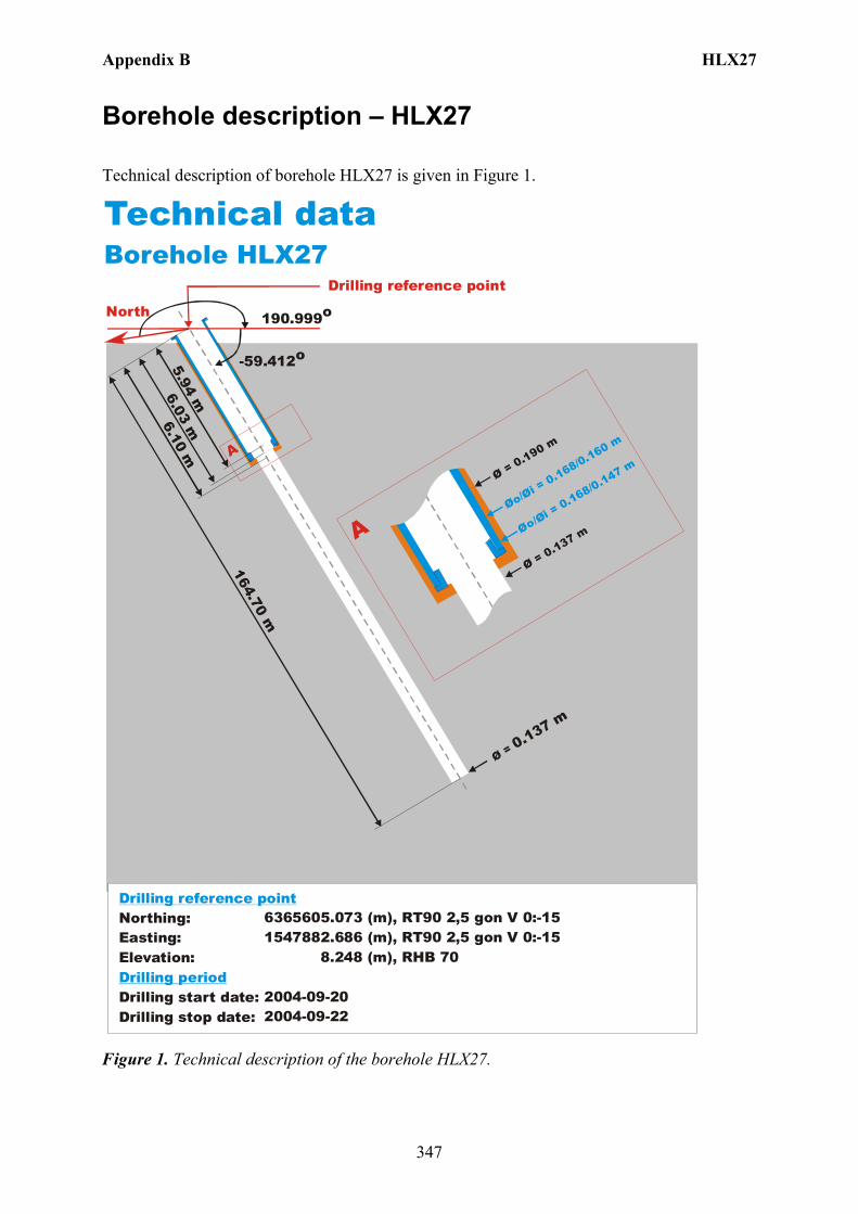
Appendix B HLX27
347
Borehole description – HLX27
Technical description of borehole HLX27 is given in Figure 1.
North
Technical dataBorehole HLX27
6365605.073 (m),(m),
8.248 (m),
2004-09-202004-09-22
RT90 2,5 gon V 0:-151547882.686 RT90 2,5 gon V 0:-15
RHB 70
-59.412o
Ø = 0.137 m
164.70 m
6.10 m
Øo/Øi = 0.168/0.160 m
Ø = 0.190 m
Ø = 0.137 m
A
A
190.999o
Northing:Easting:Elevation:
Drilling start date:Drilling stop date:
Drilling reference point
Drilling period
Øo/Øi = 0.168/0.147 m
6.03 m5.94 m
Drilling reference point
Figure 1. Technical description of the borehole HLX27.

Appendix B HLX27
348
Deviation measurement in HLX27 The only deviation measurement performed in HLX27 was with the acoustic televiewer. On the data a 31 point median filter was used to reduce oscillation in the bearing. The deviation logging activity is tabulated in Sicada Activity Log, see Table 1. The acoustic televiewer measurement (ID 13145269) is executed between borehole lengths 0 – 160.43 m. The acoustic televiewer measurements (ID 113077086 and 13114642) are error marked measurements which was not median filtered. No geomagnetic disturbance exceeding 0.5 degrees was observed on the date of the acoustic televiewer measurement, see Figure 2.
Figure 2. The geomagnetic field was observed at the Observatory in Uppsala on 2004-10-21.
Borehole deviation multiple measurements. In the calculation of Borehole deviation multiple measurements (ID 13145646) the acoustic televiewer measurement (ID 13145269) was used. Table 2 shows the deviation data for the calculation. A subset of the resulting deviation file for every approximately 20 m elevation (from Object_location) is shown in Table 3. When only one measurement is used the standard values of inclination uncertainty, 1.8 and bearing uncertainty of 4.9 is used for calculation of the radius uncertainty for every measuring level. Figure 3 show the resulting deviation data together with the other, not error marked, deviation activity listed in Table 1.
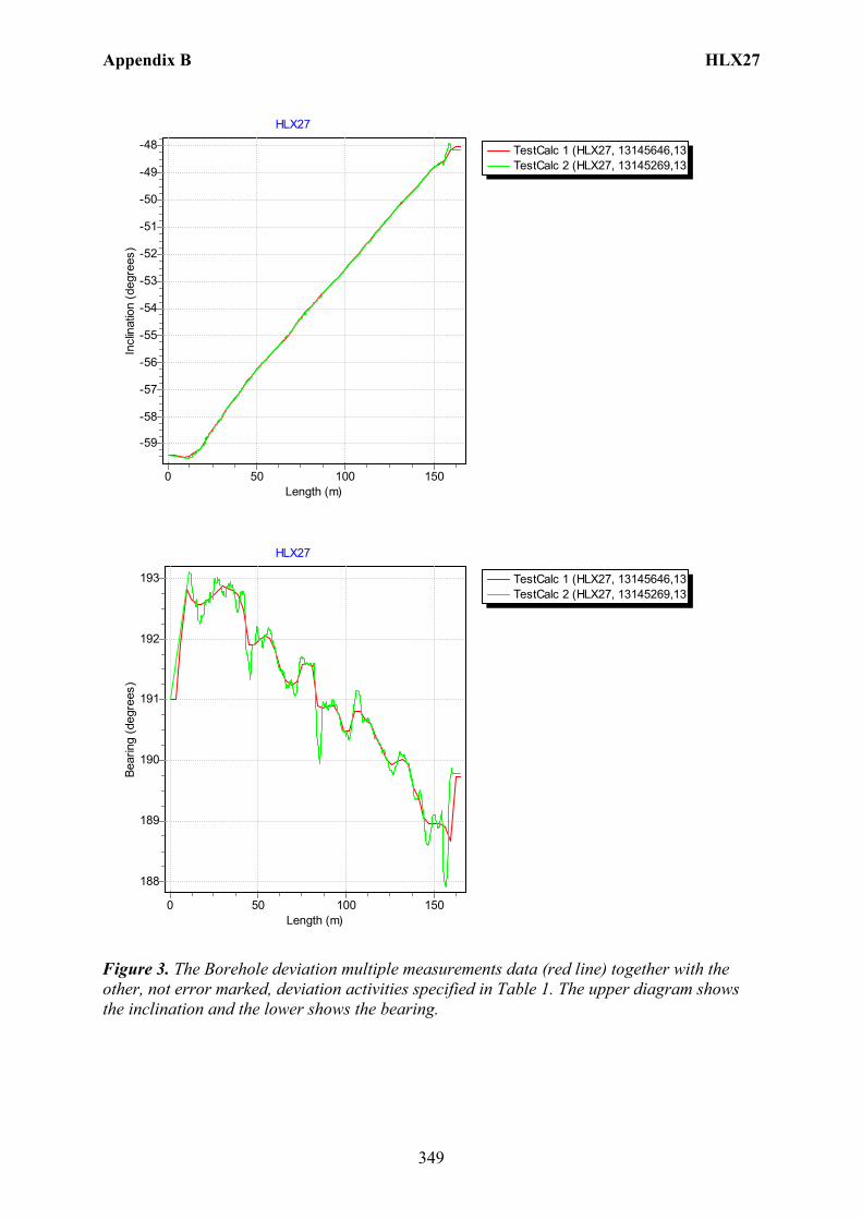
Appendix B HLX27
349
TestCalc 1 (HLX27, 13145646,13TestCalc 2 (HLX27, 13145269,13
HLX27
Length (m)150100500
Incl
inat
ion
(deg
rees
)-48
-49
-50
-51
-52
-53
-54
-55
-56
-57
-58
-59
TestCalc 1 (HLX27, 13145646,13TestCalc 2 (HLX27, 13145269,13
HLX27
Length (m)150100500
Bear
ing
(deg
rees
)
193
192
191
190
189
188
Figure 3. The Borehole deviation multiple measurements data (red line) together with the other, not error marked, deviation activities specified in Table 1. The upper diagram shows the inclination and the lower shows the bearing.
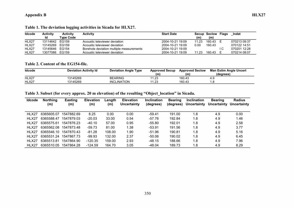
Appendix B HLX27
350
Table 1. The deviation logging activities in Sicada for HLX27. Idcode Activity
Id Activity Type Code
Activity Start Date Secup (m)
Seclow (m)
Flags _Indat
HLX27 13114642 EG159 Acoustic televiewer deviation 2004-10-21 19:09 11.23 160.43 E 070213 09:37 HLX27 13145269 EG159 Acoustic televiewer deviation 2004-10-21 19:09 0.00 160.43 070122 14:51 HLX27 13145646 EG154 Borehole deviation multiple measurements 2004-10-21 19:09 I C 070201 12:28 HLX27 13077086 EG159 Acoustic televiewer deviation 2004-10-21 19:09 11.23 160.43 E 070214 08:07
Table 2. Content of the EG154-file. Idcode Deviation Activity Id Deviation Angle Type Approved Secup
(m) Approved Seclow (m)
Man Estim Angle Uncert (degrees)
HLX27 13145269 BEARING 11.23 160.43 4.9 HLX27 13145269 INCLINATION 11.23 160.43 1.8
Table 3. Subset (for every approx. 20 m elevation) of the resulting “Object_location” in Sicada. Idcode Northing
(m) Easting
(m) Elevation
(m) Length
(m) Elevation
Uncertainty Inclination (degrees)
Bearing (degrees)
Inclination Uncertainty
Bearing Uncertainty
Radius Uncertainty
HLX27 6365605.07 1547882.69 8.25 0.00 0.00 -59.41 191.00 1.8 4.9 0.00 HLX27 6365588.47 1547879.03 -20.03 33.00 0.54 -57.76 192.84 1.8 4.9 1.46 HLX27 6365575.61 1547876.23 -40.10 57.00 0.95 -55.80 192.01 1.8 4.9 2.58 HLX27 6365562.08 1547873.48 -59.73 81.00 1.38 -53.91 191.56 1.8 4.9 3.77 HLX27 6365546.10 1547870.43 -81.28 108.00 1.90 -51.96 190.81 1.8 4.9 5.16 HLX27 6365531.24 1547867.73 -99.93 132.00 2.37 -50.06 190.02 1.8 4.9 6.45 HLX27 6365513.81 1547864.90 -120.35 159.00 2.93 -48.15 188.66 1.8 4.9 7.96 HLX27 6365510.05 1547864.28 -124.59 164.70 3.05 -48.04 189.73 1.8 4.9 8.29

Appendix B HLX28
351
Borehole description – HLX28
Technical description of borehole HLX28 is given in Figure 1.
North
Technical dataBorehole HLX28
6365861.704 (m),(m),
13.424 (m),
2004-09-292004-10-02
RT90 2,5 gon V 0:-151546834.473 RT90 2,5 gon V 0:-15
RHB 70
-59.485o
Ø = 0.136 m
154.20 m
6.10 m
Øo/Øi = 0.168/0.160 m
Ø = 0.190 m
Ø = 0.136 m
A
A
201.375o
Northing:Easting:Elevation:
Drilling start date:Drilling stop date:
Drilling reference point
Drilling period
Øo/Øi = 0.168/0.147 m
6.03 m5.94 m
Drilling reference point
Figure 1. Technical description of the borehole HLX28.
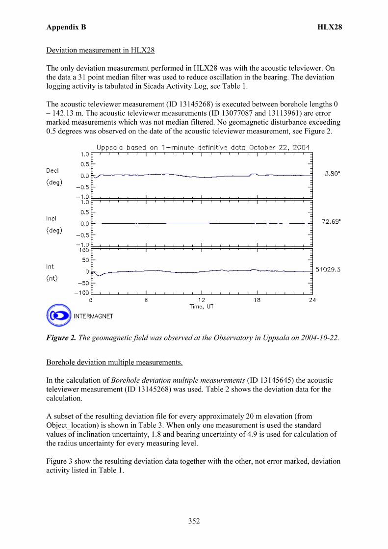
Appendix B HLX28
352
Deviation measurement in HLX28 The only deviation measurement performed in HLX28 was with the acoustic televiewer. On the data a 31 point median filter was used to reduce oscillation in the bearing. The deviation logging activity is tabulated in Sicada Activity Log, see Table 1. The acoustic televiewer measurement (ID 13145268) is executed between borehole lengths 0 – 142.13 m. The acoustic televiewer measurements (ID 13077087 and 13113961) are error marked measurements which was not median filtered. No geomagnetic disturbance exceeding 0.5 degrees was observed on the date of the acoustic televiewer measurement, see Figure 2.
Figure 2. The geomagnetic field was observed at the Observatory in Uppsala on 2004-10-22.
Borehole deviation multiple measurements. In the calculation of Borehole deviation multiple measurements (ID 13145645) the acoustic televiewer measurement (ID 13145268) was used. Table 2 shows the deviation data for the calculation. A subset of the resulting deviation file for every approximately 20 m elevation (from Object_location) is shown in Table 3. When only one measurement is used the standard values of inclination uncertainty, 1.8 and bearing uncertainty of 4.9 is used for calculation of the radius uncertainty for every measuring level. Figure 3 show the resulting deviation data together with the other, not error marked, deviation activity listed in Table 1.
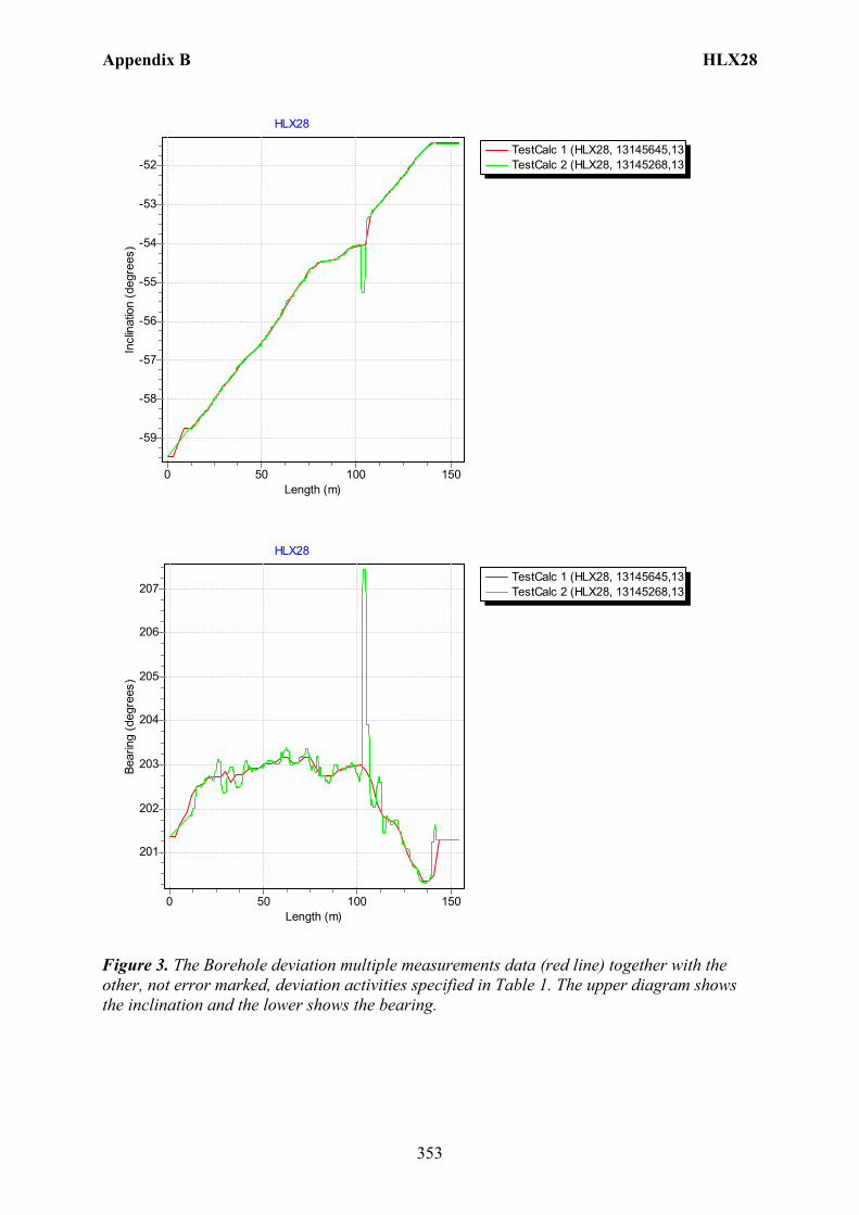
Appendix B HLX28
353
TestCalc 1 (HLX28, 13145645,13TestCalc 2 (HLX28, 13145268,13
HLX28
Length (m)150100500
Incl
inat
ion
(deg
rees
)
-52
-53
-54
-55
-56
-57
-58
-59
TestCalc 1 (HLX28, 13145645,13TestCalc 2 (HLX28, 13145268,13
HLX28
Length (m)150100500
Bear
ing
(deg
rees
)
207
206
205
204
203
202
201
Figure 3. The Borehole deviation multiple measurements data (red line) together with the other, not error marked, deviation activities specified in Table 1. The upper diagram shows the inclination and the lower shows the bearing.
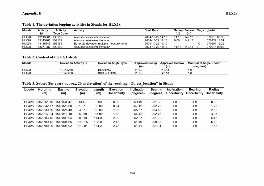
Appendix B HLX28
354
Table 1. The deviation logging activities in Sicada for HLX28. Idcode Activity
Id Activity Type Code
Activity Start Date Secup (m)
Seclow (m)
Flags _Indat
HLX28 13113961 EG159 Acoustic televiewer deviation 2004-10-22 14:10 11.13 142.13 E 070213 09:38 HLX28 13145268 EG159 Acoustic televiewer deviation 2004-10-22 14:10 0.00 142.13 070122 14:51 HLX28 13145645 EG154 Borehole deviation multiple measurements 2004-10-22 14:10 I C 070201 12:29 HLX28 13077087 EG159 Acoustic televiewer deviation 2004-10-22 14:10 11.13 142.13 E 070214 08:09
Table 2. Content of the EG154-file. Idcode Deviation Activity Id Deviation Angle Type Approved Secup
(m) Approved Seclow (m)
Man Estim Angle Uncert (degrees)
HLX28 13145268 BEARING 11.13 142.13 4.9 HLX28 13145268 INCLINATION 11.13 142.13 1.8
Table 3. Subset (for every approx. 20 m elevation) of the resulting “Object_location” in Sicada. Idcode Northing
(m) Easting
(m) Elevation
(m) Length
(m) Elevation
Uncertainty Inclination (degrees)
Bearing (degrees)
Inclination Uncertainty
Bearing Uncertainty
Radius Uncertainty
HLX28 6365861.70 1546834.47 13.42 0.00 0.00 -59.49 201.38 1.8 4.9 0.00 HLX28 6365842.77 1546826.68 -19.77 39.00 0.64 -57.12 202.78 1.8 4.9 1.75 HLX28 6365830.56 1546821.49 -39.77 63.00 1.06 -55.57 203.18 1.8 4.9 2.89 HLX28 6365817.84 1546816.10 -59.38 87.00 1.50 -54.42 202.76 1.8 4.9 4.07 HLX28 6365803.15 1546809.94 -81.19 114.00 2.00 -52.87 201.82 1.8 4.9 5.43 HLX28 6365789.42 1546804.65 -100.15 138.00 2.46 -51.49 200.35 1.8 4.9 6.69 HLX28 6365780.00 1546801.02 -112.81 154.20 2.78 -51.41 201.31 1.8 4.9 7.56
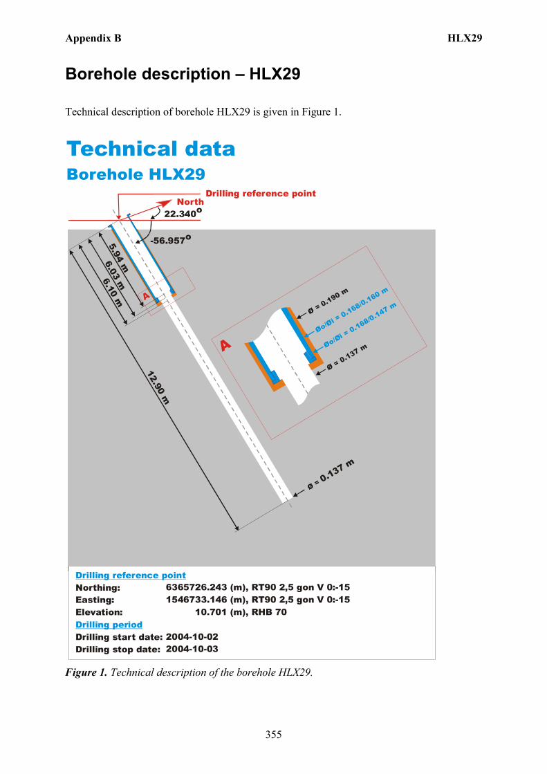
Appendix B HLX29
355
Borehole description – HLX29
Technical description of borehole HLX29 is given in Figure 1.
North
Technical dataBorehole HLX29
6365726.243 (m),(m),
10.701 (m),
2004-10-022004-10-03
RT90 2,5 gon V 0:-151546733.146 RT90 2,5 gon V 0:-15
RHB 70
-56.957o
Ø = 0.137 m
12.90 m
6.10 m
Øo/Øi = 0.168/0.160 m
Ø = 0.190 m
Ø = 0.137 m
A
A
22.340o
Northing:Easting:Elevation:
Drilling start date:Drilling stop date:
Drilling reference point
Drilling period
Øo/Øi = 0.168/0.147 m
6.03 m5.94 m
Drilling reference point
Figure 1. Technical description of the borehole HLX29.

Appendix B HLX29
356
Borehole direction surveying in HLX29 There is no deviation measurement performed in HLX29. Only the borehole direction surveying was performed from the start of the borehole. Here the starting bearing and inclination is presented in Figure 1. Borehole deviation multiple measurements. In the calculation of Borehole deviation multiple measurements (ID 13149810) the borehole direction surveying (ID 13054592) from start of the borehole was used, Table 1. Table 2 shows the deviation data for the calculation. A subset of the resulting deviation file from Object_location is shown in Table 3. The uncertainty in inclination is calculated according to: –0.000092*(borehole_length)2 + 0.049*borehole length + 1.16 + 1.8. The uncertainty in bearing is calculated according to: 0.05*borehole_length + 2.5 + 4.9. The borehole deviation multiple measurement (ID 13146887) was error marked and replaced with (ID 13149810) which was based on the uncertainty calculation above. Figure 2 shows the inclination and bearing of the borehole plotted as a straight line.

Appendix B HLX29
357
TestCalc 1 (HLX29, 13149810,13
HLX29
Length (m)121086420
Incl
inat
ion
(deg
rees
)
-52
-53
-54
-55
-56
-57
-58
-59
-60
-61
-62
TestCalc 1 (HLX29, 13149810,13
HLX29
Length (m)121086420
Bear
ing
(deg
rees
)
24
23
22
21
Figure 2. The Borehole deviation multiple measurements data (red line) plotted as a straight line. The upper diagram shows the inclination and the lower shows the bearing.
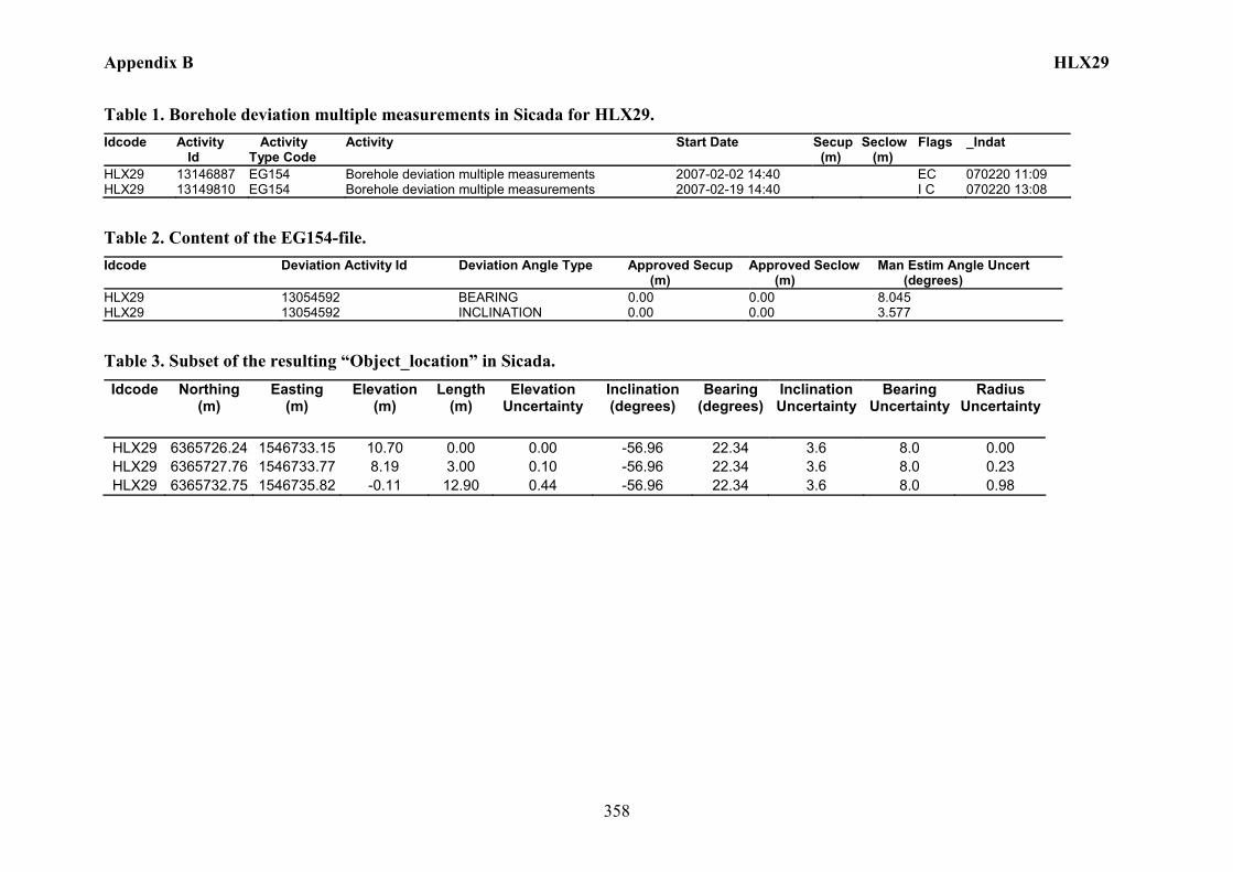
Appendix B HLX29
358
Table 1. Borehole deviation multiple measurements in Sicada for HLX29. Idcode Activity
Id Activity Type Code
Activity Start Date Secup (m)
Seclow (m)
Flags _Indat
HLX29 13146887 EG154 Borehole deviation multiple measurements 2007-02-02 14:40 EC 070220 11:09 HLX29 13149810 EG154 Borehole deviation multiple measurements 2007-02-19 14:40 I C 070220 13:08
Table 2. Content of the EG154-file. Idcode Deviation Activity Id Deviation Angle Type Approved Secup
(m) Approved Seclow (m)
Man Estim Angle Uncert (degrees)
HLX29 13054592 BEARING 0.00 0.00 8.045 HLX29 13054592 INCLINATION 0.00 0.00 3.577
Table 3. Subset of the resulting “Object_location” in Sicada. Idcode Northing
(m) Easting
(m) Elevation
(m) Length
(m) Elevation
Uncertainty Inclination (degrees)
Bearing (degrees)
Inclination Uncertainty
Bearing Uncertainty
Radius Uncertainty
HLX29 6365726.24 1546733.15 10.70 0.00 0.00 -56.96 22.34 3.6 8.0 0.00 HLX29 6365727.76 1546733.77 8.19 3.00 0.10 -56.96 22.34 3.6 8.0 0.23 HLX29 6365732.75 1546735.82 -0.11 12.90 0.44 -56.96 22.34 3.6 8.0 0.98
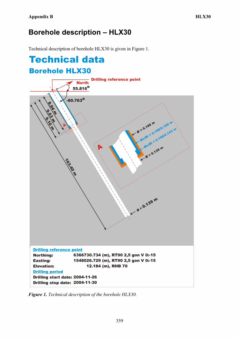
Appendix B HLX30
359
Borehole description – HLX30
Technical description of borehole HLX30 is given in Figure 1.
North
Technical dataBorehole HLX30
6366730.734 (m),(m),
12.184 (m),
2004-11-262004-11-30
RT90 2,5 gon V 0:-151548026.729 RT90 2,5 gon V 0:-15
RHB 70
-60.763o
Ø = 0.139 m
163.40 m
9.10 m
Øo/Øi = 0.168/0.160 m
Ø = 0.190 m
Ø = 0.139 m
A
A
55.816o
Northing:Easting:Elevation:
Drilling start date:Drilling stop date:
Drilling reference point
Drilling period
Øo/Øi = 0.168/0.143 m
9.03 m8.94 m
Drilling reference point
Figure 1. Technical description of the borehole HLX30.

Appendix B HLX30
360
Deviation measurement in HLX30 The only deviation measurement performed in HLX30 was with the Mac/acc, Flexit instrument. The deviation logging activity is tabulated in Sicada Activity Log, see Table 1. Two Mag/acc measurements (ID 13142279 and 13138472) were executed down and up the borehole between the length 0 – 159.00 m, with the Flexit instrument. Corrections of measured data are shown in the File References (Sicada) for the measurements. The Mac/acc measurements (ID 13080862 and 13117397) are error marked measurements with adjusted bearing and inclination mainly in the first parts of the borehole. No geomagnetic disturbance exceeding 0.5 degrees was observed on the date and time of the Mag/acc measurements, see Figure 2.
Figure 2. The geomagnetic field was observed at the Observatory in Uppsala on 2005-08-31.
Borehole deviation multiple measurements. In the calculation of Borehole deviation multiple measurements (ID 13144026) the two Mag/acc measurements (ID 13142279 and 13138472) were used. Table 2 shows the deviation data for the calculation. A subset of the resulting deviation file for every approximately 20 m elevation (from Object_location) is shown in Table 3. The inclination and bearing uncertainties are calculated automatically, and based on these values the “Radius uncertainty” is calculated for every measuring level. Figure 3 show the resulting deviation data together with the other, not error marked, deviation activities listed in Table 1.
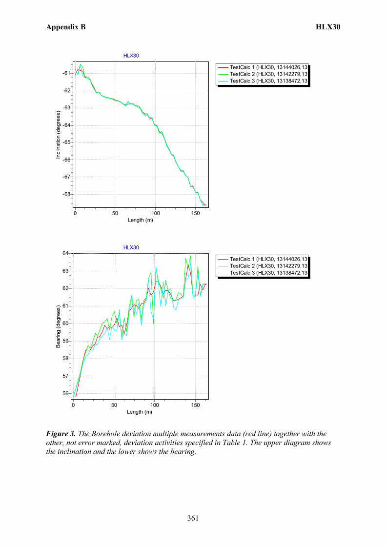
Appendix B HLX30
361
TestCalc 1 (HLX30, 13144026,13TestCalc 2 (HLX30, 13142279,13TestCalc 3 (HLX30, 13138472,13
HLX30
Length (m)150100500
Incl
inat
ion
(deg
rees
)
-61
-62
-63
-64
-65
-66
-67
-68
TestCalc 1 (HLX30, 13144026,13TestCalc 2 (HLX30, 13142279,13TestCalc 3 (HLX30, 13138472,13
HLX30
Length (m)150100500
Bear
ing
(deg
rees
)
64
63
62
61
60
59
58
57
56
Figure 3. The Borehole deviation multiple measurements data (red line) together with the other, not error marked, deviation activities specified in Table 1. The upper diagram shows the inclination and the lower shows the bearing.
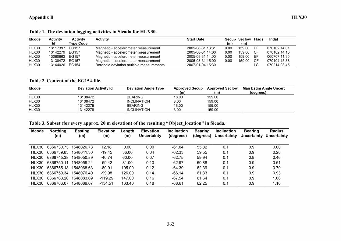
Appendix B HLX30
362
Table 1. The deviation logging activities in Sicada for HLX30. Idcode Activity
Id Activity Type Code
Activity Start Date Secup (m)
Seclow (m)
Flags _Indat
HLX30 13117397 EG157 Magnetic - accelerometer measurement 2005-08-31 13:31 0.00 159.00 EF 070102 14:01 HLX30 13142279 EG157 Magnetic - accelerometer measurement 2005-08-31 14:00 0.00 159.00 CF 070102 14:15 HLX30 13080862 EG157 Magnetic - accelerometer measurement 2005-08-31 14:00 0.00 159.00 EF 060707 11:35 HLX30 13138472 EG157 Magnetic - accelerometer measurement 2005-08-31 15:00 0.00 159.00 CF 070104 15:36 HLX30 13144026 EG154 Borehole deviation multiple measurements 2007-01-04 15:30 I C 070214 08:45
Table 2. Content of the EG154-file. Idcode Deviation Activity Id Deviation Angle Type Approved Secup
(m) Approved Seclow (m)
Man Estim Angle Uncert (degrees)
HLX30 13138472 BEARING 18.00 159.00 HLX30 13138472 INCLINATION 3.00 159.00 HLX30 13142279 BEARING 18.00 159.00 HLX30 13142279 INCLINATION 3.00 159.00
Table 3. Subset (for every approx. 20 m elevation) of the resulting “Object_location” in Sicada. Idcode Northing
(m) Easting
(m) Elevation
(m) Length
(m) Elevation
Uncertainty Inclination (degrees)
Bearing (degrees)
Inclination Uncertainty
Bearing Uncertainty
Radius Uncertainty
HLX30 6366730.73 1548026.73 12.18 0.00 0.00 -61.04 55.82 0.1 0.9 0.00 HLX30 6366739.83 1548041.30 -19.45 36.00 0.04 -62.33 59.55 0.1 0.9 0.28 HLX30 6366745.38 1548050.89 -40.74 60.00 0.07 -62.75 59.94 0.1 0.9 0.46 HLX30 6366750.11 1548059.24 -59.42 81.00 0.10 -62.97 60.88 0.1 0.9 0.61 HLX30 6366755.18 1548068.63 -80.91 105.00 0.12 -64.39 62.39 0.1 0.9 0.79 HLX30 6366759.34 1548076.40 -99.98 126.00 0.14 -66.14 61.33 0.1 0.9 0.93 HLX30 6366763.20 1548083.69 -119.29 147.00 0.16 -67.54 61.64 0.1 0.9 1.06 HLX30 6366766.07 1548089.07 -134.51 163.40 0.18 -68.61 62.25 0.1 0.9 1.16
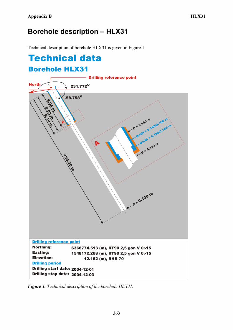
Appendix B HLX31
363
Borehole description – HLX31
Technical description of borehole HLX31 is given in Figure 1.
North
Technical dataBorehole HLX31
6366774.513 (m),(m),
12.162 (m),
2004-12-012004-12-03
1548172.268 RT90 2,5 gon V 0:-15 RHB 70
RT90 2,5 gon V 0:-15
-58.758o
Ø = 0.139 m
133.20 m
9.10 m
Øo/Øi = 0.168/0.160 m
Ø = 0.190 m
Ø = 0.139 m
A
A
231.772o
Northing:Easting:Elevation:
Drilling start date:Drilling stop date:
Drilling reference point
Drilling period
Øo/Øi = 0.168/0.143 m
9.03 m8.94 m
Drilling reference point
Figure 1. Technical description of the borehole HLX31.
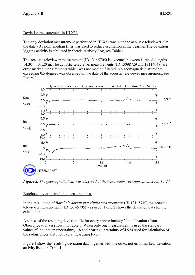
Appendix B HLX31
364
Deviation measurement in HLX31 The only deviation measurement performed in HLX31 was with the acoustic televiewer. On the data a 31 point median filter was used to reduce oscillation in the bearing. The deviation logging activity is tabulated in Sicada Activity Log, see Table 1. The acoustic televiewer measurement (ID 13145705) is executed between borehole lengths 14.30 – 131.20 m. The acoustic televiewer measurements (ID 13098729 and 13114648) are error marked measurements which was not median filtered. No geomagnetic disturbance exceeding 0.5 degrees was observed on the date of the acoustic televiewer measurement, see Figure 2.
Figure 2. The geomagnetic field was observed at the Observatory in Uppsala on 2005-10-27.
Borehole deviation multiple measurements. In the calculation of Borehole deviation multiple measurements (ID 13145740) the acoustic televiewer measurement (ID 13145705) was used. Table 2 shows the deviation data for the calculation. A subset of the resulting deviation file for every approximately 20 m elevation (from Object_location) is shown in Table 3. When only one measurement is used the standard values of inclination uncertainty, 1.8 and bearing uncertainty of 4.9 is used for calculation of the radius uncertainty for every measuring level. Figure 3 show the resulting deviation data together with the other, not error marked, deviation activity listed in Table 1.

Appendix B HLX31
365
TestCalc 1 (HLX31, 13145740,13TestCalc 2 (HLX31, 13145705,13
HLX31
Length (m)100500
Incl
inat
ion
(deg
rees
)
-59
-60
-61
-62
-63
TestCalc 1 (HLX31, 13145740,13TestCalc 2 (HLX31, 13145705,13
HLX31
Length (m)100500
Bear
ing
(deg
rees
)
237
236
235
234
233
232
Figure 3. The Borehole deviation multiple measurements data (red line) together with the other, not error marked, deviation activities specified in Table 1. The upper diagram shows the inclination and the lower shows the bearing.
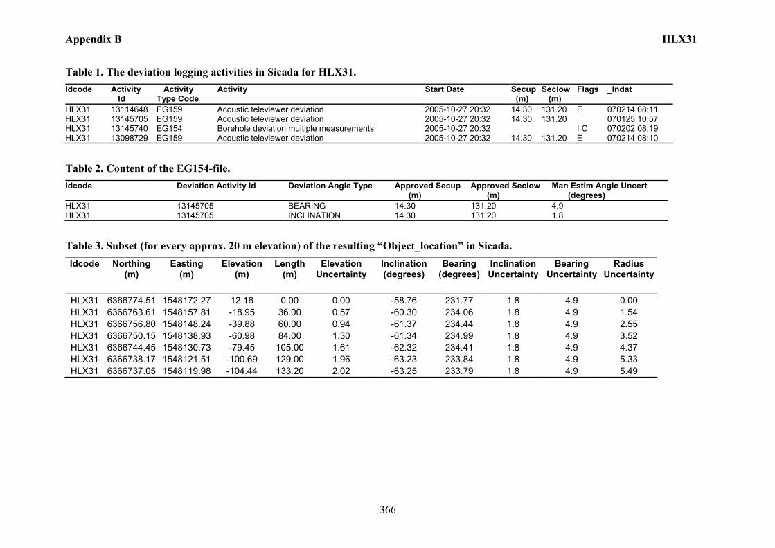
Appendix B HLX31
366
Table 1. The deviation logging activities in Sicada for HLX31. Idcode Activity
Id Activity Type Code
Activity Start Date Secup (m)
Seclow (m)
Flags _Indat
HLX31 13114648 EG159 Acoustic televiewer deviation 2005-10-27 20:32 14.30 131.20 E 070214 08:11 HLX31 13145705 EG159 Acoustic televiewer deviation 2005-10-27 20:32 14.30 131.20 070125 10:57 HLX31 13145740 EG154 Borehole deviation multiple measurements 2005-10-27 20:32 I C 070202 08:19 HLX31 13098729 EG159 Acoustic televiewer deviation 2005-10-27 20:32 14.30 131.20 E 070214 08:10
Table 2. Content of the EG154-file. Idcode Deviation Activity Id Deviation Angle Type Approved Secup
(m) Approved Seclow (m)
Man Estim Angle Uncert (degrees)
HLX31 13145705 BEARING 14.30 131.20 4.9 HLX31 13145705 INCLINATION 14.30 131.20 1.8
Table 3. Subset (for every approx. 20 m elevation) of the resulting “Object_location” in Sicada. Idcode Northing
(m) Easting
(m) Elevation
(m) Length
(m) Elevation
Uncertainty Inclination (degrees)
Bearing (degrees)
Inclination Uncertainty
Bearing Uncertainty
Radius Uncertainty
HLX31 6366774.51 1548172.27 12.16 0.00 0.00 -58.76 231.77 1.8 4.9 0.00 HLX31 6366763.61 1548157.81 -18.95 36.00 0.57 -60.30 234.06 1.8 4.9 1.54 HLX31 6366756.80 1548148.24 -39.88 60.00 0.94 -61.37 234.44 1.8 4.9 2.55 HLX31 6366750.15 1548138.93 -60.98 84.00 1.30 -61.34 234.99 1.8 4.9 3.52 HLX31 6366744.45 1548130.73 -79.45 105.00 1.61 -62.32 234.41 1.8 4.9 4.37 HLX31 6366738.17 1548121.51 -100.69 129.00 1.96 -63.23 233.84 1.8 4.9 5.33 HLX31 6366737.05 1548119.98 -104.44 133.20 2.02 -63.25 233.79 1.8 4.9 5.49
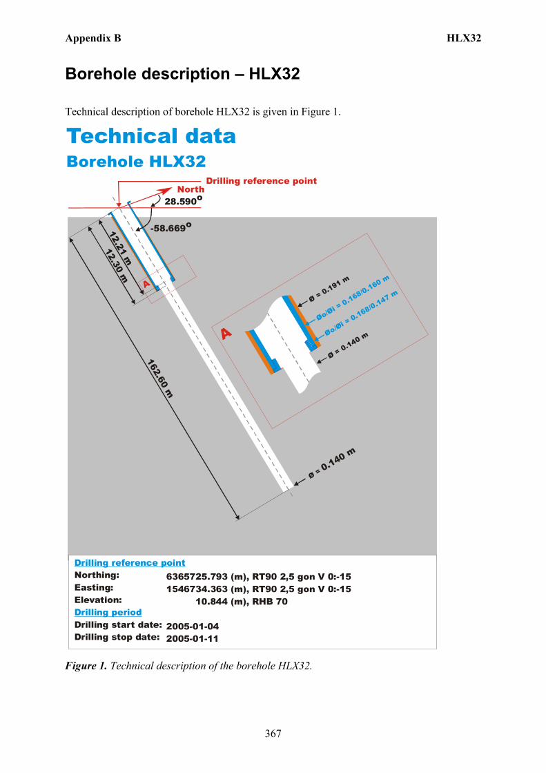
Appendix B HLX32
367
Borehole description – HLX32
Technical description of borehole HLX32 is given in Figure 1.
North
Technical dataBorehole HLX32
6365725.793 (m),(m),
10.844 (m),
2005-01-042005-01-11
1546734.363 RT90 2,5 gon V 0:-15 RHB 70
RT90 2,5 gon V 0:-15
-58.669o
Ø = 0.140 m
162.60 m
Øo/Øi = 0.168/0.160 m
Ø = 0.191 m
Ø = 0.140 m
A
A
28.590o
Northing:Easting:Elevation:
Drilling start date:Drilling stop date:
Drilling reference point
Drilling period
Øo/Øi = 0.168/0.147 m
12.30 m12.21 m
Drilling reference point
Figure 1. Technical description of the borehole HLX32.
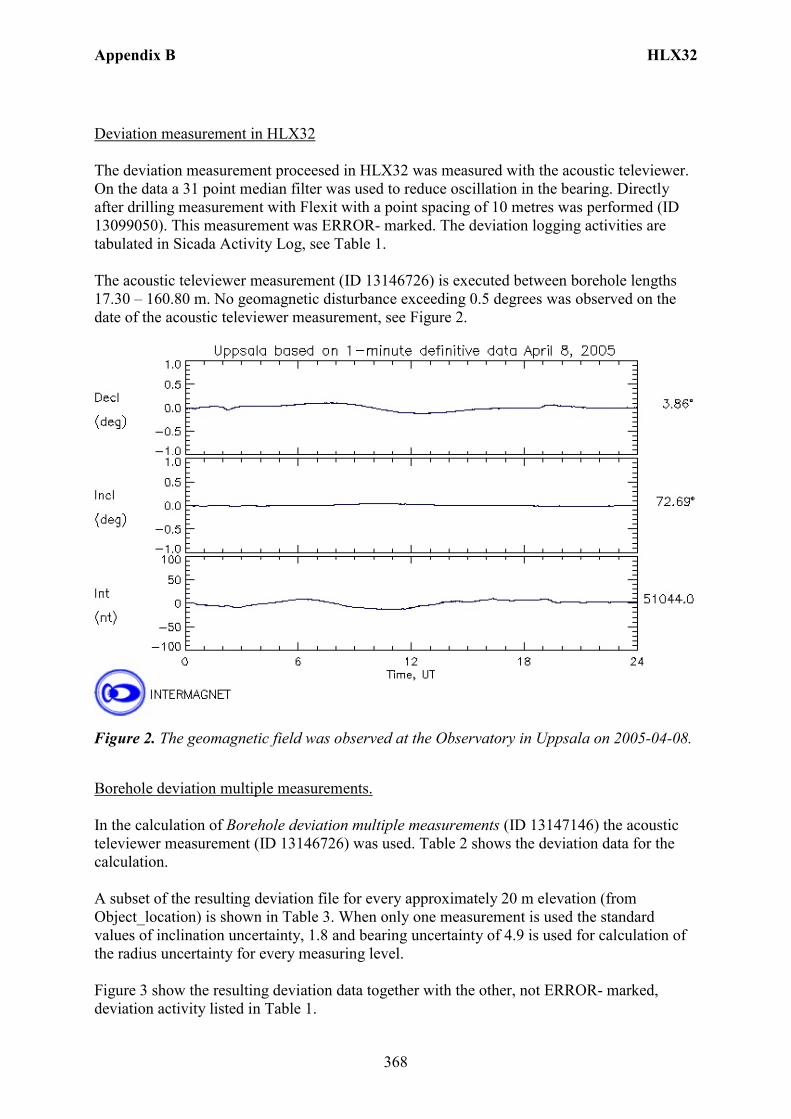
Appendix B HLX32
368
Deviation measurement in HLX32 The deviation measurement proceesed in HLX32 was measured with the acoustic televiewer. On the data a 31 point median filter was used to reduce oscillation in the bearing. Directly after drilling measurement with Flexit with a point spacing of 10 metres was performed (ID 13099050). This measurement was ERROR- marked. The deviation logging activities are tabulated in Sicada Activity Log, see Table 1. The acoustic televiewer measurement (ID 13146726) is executed between borehole lengths 17.30 – 160.80 m. No geomagnetic disturbance exceeding 0.5 degrees was observed on the date of the acoustic televiewer measurement, see Figure 2.
Figure 2. The geomagnetic field was observed at the Observatory in Uppsala on 2005-04-08.
Borehole deviation multiple measurements. In the calculation of Borehole deviation multiple measurements (ID 13147146) the acoustic televiewer measurement (ID 13146726) was used. Table 2 shows the deviation data for the calculation. A subset of the resulting deviation file for every approximately 20 m elevation (from Object_location) is shown in Table 3. When only one measurement is used the standard values of inclination uncertainty, 1.8 and bearing uncertainty of 4.9 is used for calculation of the radius uncertainty for every measuring level. Figure 3 show the resulting deviation data together with the other, not ERROR- marked, deviation activity listed in Table 1.
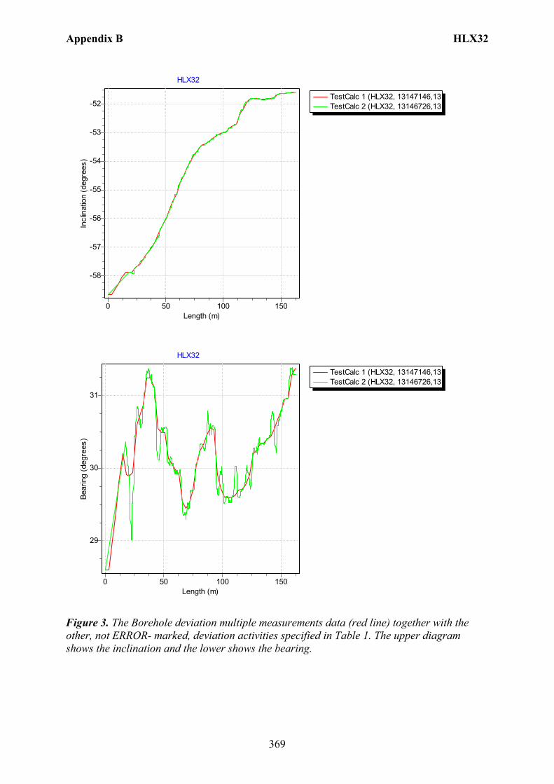
Appendix B HLX32
369
TestCalc 1 (HLX32, 13147146,13TestCalc 2 (HLX32, 13146726,13
HLX32
Length (m)150100500
Incl
inat
ion
(deg
rees
)
-52
-53
-54
-55
-56
-57
-58
TestCalc 1 (HLX32, 13147146,13TestCalc 2 (HLX32, 13146726,13
HLX32
Length (m)150100500
Bear
ing
(deg
rees
)
31
30
29
Figure 3. The Borehole deviation multiple measurements data (red line) together with the other, not ERROR- marked, deviation activities specified in Table 1. The upper diagram shows the inclination and the lower shows the bearing.
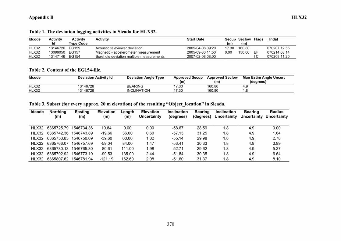
Appendix B HLX32
370
Table 1. The deviation logging activities in Sicada for HLX32. Idcode Activity
Id Activity Type Code
Activity Start Date Secup (m)
Seclow (m)
Flags _Indat
HLX32 13146726 EG159 Acoustic televiewer deviation 2005-04-08 09:20 17.30 160.80 070207 12:55 HLX32 13099050 EG157 Magnetic - accelerometer measurement 2005-09-30 11:50 0.00 150.00 EF 070214 08:14 HLX32 13147146 EG154 Borehole deviation multiple measurements 2007-02-08 08:00 I C 070208 11:20
Table 2. Content of the EG154-file. Idcode Deviation Activity Id Deviation Angle Type Approved Secup
(m) Approved Seclow (m)
Man Estim Angle Uncert (degrees)
HLX32 13146726 BEARING 17.30 160.80 4.9 HLX32 13146726 INCLINATION 17.30 160.80 1.8
Table 3. Subset (for every approx. 20 m elevation) of the resulting “Object_location” in Sicada. Idcode Northing
(m) Easting
(m) Elevation
(m) Length
(m) Elevation
Uncertainty Inclination (degrees)
Bearing (degrees)
Inclination Uncertainty
Bearing Uncertainty
Radius Uncertainty
HLX32 6365725.79 1546734.36 10.84 0.00 0.00 -58.67 28.59 1.8 4.9 0.00 HLX32 6365742.36 1546743.89 -19.66 36.00 0.60 -57.13 31.25 1.8 4.9 1.64 HLX32 6365753.85 1546750.69 -39.60 60.00 1.02 -55.14 29.98 1.8 4.9 2.78 HLX32 6365766.07 1546757.69 -59.04 84.00 1.47 -53.41 30.33 1.8 4.9 3.99 HLX32 6365780.13 1546765.80 -80.61 111.00 1.98 -52.71 29.62 1.8 4.9 5.37 HLX32 6365792.92 1546773.19 -99.53 135.00 2.44 -51.84 30.35 1.8 4.9 6.64 HLX32 6365807.62 1546781.94 -121.19 162.60 2.98 -51.60 31.37 1.8 4.9 8.10

Appendix B HLX33
371
Borehole description – HLX33
Technical description of borehole HLX33 is given in Figure 1.
North
Technical dataBorehole HLX33
6366471.744 (m),(m),
12.201 (m),
2004-12-172004-12-20
RT90 2,5 gon V 0:-151548562.705 RT90 2,5 gon V 0:-15
RHB 70
-58.763o
Ø = 0.139 m
202.10 m
9.10 m
Øo/Øi = 0.168/0.160 m
Ø = 0.190 m
Ø = 0.139 m
A
A
21.769o
Northing:Easting:Elevation:
Drilling start date:Drilling stop date:
Drilling reference point
Drilling period
Øo/Øi = 0.168/0.143 m
9.03 m8.94 m
Drilling reference point
Figure 1. Technical description of the borehole HLX33.
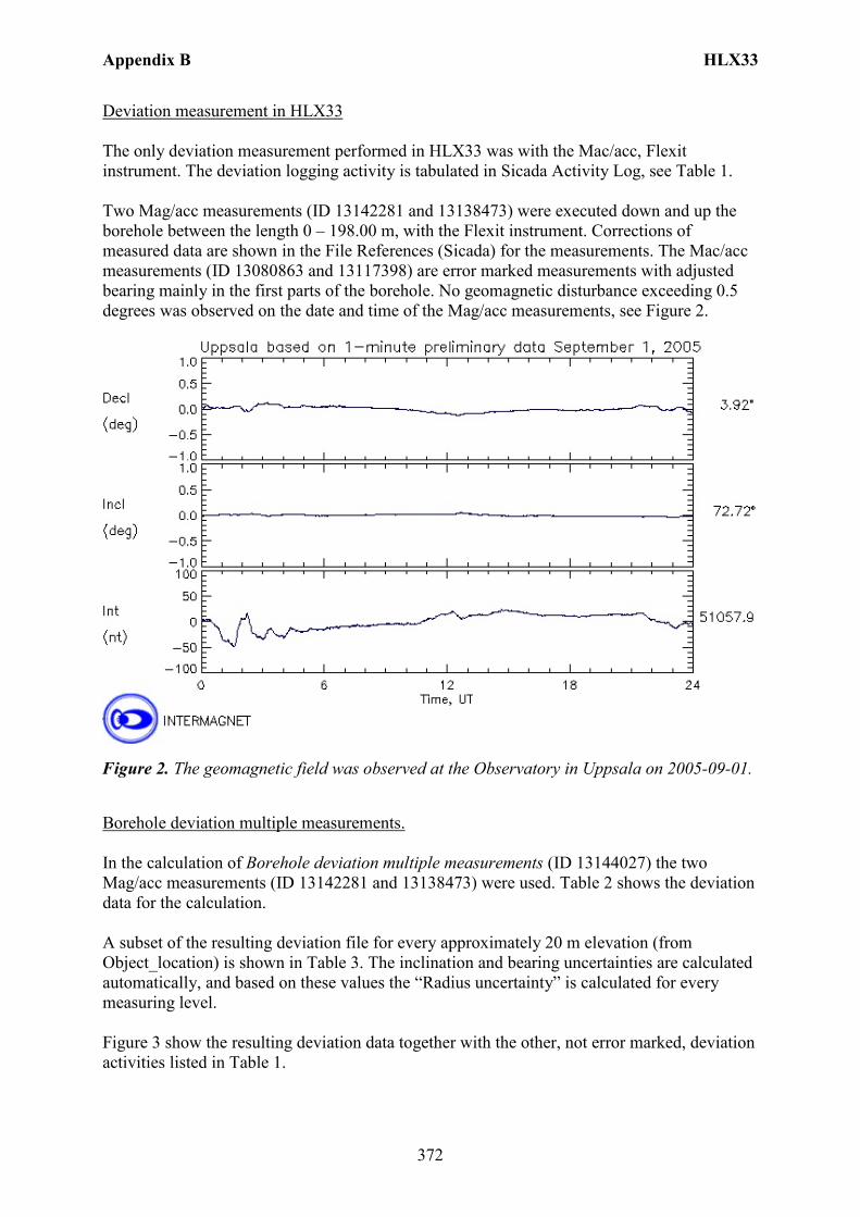
Appendix B HLX33
372
Deviation measurement in HLX33 The only deviation measurement performed in HLX33 was with the Mac/acc, Flexit instrument. The deviation logging activity is tabulated in Sicada Activity Log, see Table 1. Two Mag/acc measurements (ID 13142281 and 13138473) were executed down and up the borehole between the length 0 – 198.00 m, with the Flexit instrument. Corrections of measured data are shown in the File References (Sicada) for the measurements. The Mac/acc measurements (ID 13080863 and 13117398) are error marked measurements with adjusted bearing mainly in the first parts of the borehole. No geomagnetic disturbance exceeding 0.5 degrees was observed on the date and time of the Mag/acc measurements, see Figure 2.
Figure 2. The geomagnetic field was observed at the Observatory in Uppsala on 2005-09-01.
Borehole deviation multiple measurements. In the calculation of Borehole deviation multiple measurements (ID 13144027) the two Mag/acc measurements (ID 13142281 and 13138473) were used. Table 2 shows the deviation data for the calculation. A subset of the resulting deviation file for every approximately 20 m elevation (from Object_location) is shown in Table 3. The inclination and bearing uncertainties are calculated automatically, and based on these values the “Radius uncertainty” is calculated for every measuring level. Figure 3 show the resulting deviation data together with the other, not error marked, deviation activities listed in Table 1.
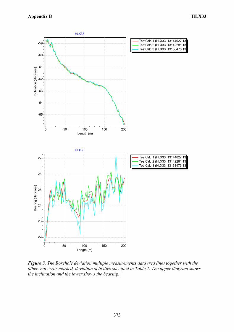
Appendix B HLX33
373
TestCalc 1 (HLX33, 13144027,13TestCalc 2 (HLX33, 13142281,13TestCalc 3 (HLX33, 13138473,13
HLX33
Length (m)200150100500
Incl
inat
ion
(deg
rees
)
-59
-60
-61
-62
-63
-64
-65
TestCalc 1 (HLX33, 13144027,13TestCalc 2 (HLX33, 13142281,13TestCalc 3 (HLX33, 13138473,13
HLX33
Length (m)200150100500
Bear
ing
(deg
rees
)
27
26
25
24
23
22
Figure 3. The Borehole deviation multiple measurements data (red line) together with the other, not error marked, deviation activities specified in Table 1. The upper diagram shows the inclination and the lower shows the bearing.
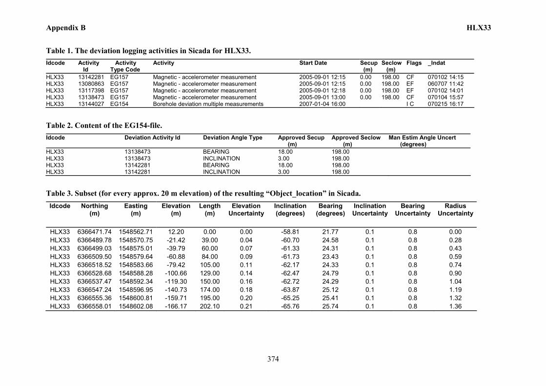
Appendix B HLX33
374
Table 1. The deviation logging activities in Sicada for HLX33. Idcode Activity
Id Activity Type Code
Activity Start Date Secup (m)
Seclow (m)
Flags _Indat
HLX33 13142281 EG157 Magnetic - accelerometer measurement 2005-09-01 12:15 0.00 198.00 CF 070102 14:15 HLX33 13080863 EG157 Magnetic - accelerometer measurement 2005-09-01 12:15 0.00 198.00 EF 060707 11:42 HLX33 13117398 EG157 Magnetic - accelerometer measurement 2005-09-01 12:18 0.00 198.00 EF 070102 14:01 HLX33 13138473 EG157 Magnetic - accelerometer measurement 2005-09-01 13:00 0.00 198.00 CF 070104 15:57 HLX33 13144027 EG154 Borehole deviation multiple measurements 2007-01-04 16:00 I C 070215 16:17
Table 2. Content of the EG154-file. Idcode Deviation Activity Id Deviation Angle Type Approved Secup
(m) Approved Seclow (m)
Man Estim Angle Uncert (degrees)
HLX33 13138473 BEARING 18.00 198.00 HLX33 13138473 INCLINATION 3.00 198.00 HLX33 13142281 BEARING 18.00 198.00 HLX33 13142281 INCLINATION 3.00 198.00
Table 3. Subset (for every approx. 20 m elevation) of the resulting “Object_location” in Sicada. Idcode Northing
(m) Easting
(m) Elevation
(m) Length
(m) Elevation
Uncertainty Inclination (degrees)
Bearing (degrees)
Inclination Uncertainty
Bearing Uncertainty
Radius Uncertainty
HLX33 6366471.74 1548562.71 12.20 0.00 0.00 -58.81 21.77 0.1 0.8 0.00 HLX33 6366489.78 1548570.75 -21.42 39.00 0.04 -60.70 24.58 0.1 0.8 0.28 HLX33 6366499.03 1548575.01 -39.79 60.00 0.07 -61.33 24.31 0.1 0.8 0.43 HLX33 6366509.50 1548579.64 -60.88 84.00 0.09 -61.73 23.43 0.1 0.8 0.59 HLX33 6366518.52 1548583.66 -79.42 105.00 0.11 -62.17 24.33 0.1 0.8 0.74 HLX33 6366528.68 1548588.28 -100.66 129.00 0.14 -62.47 24.79 0.1 0.8 0.90 HLX33 6366537.47 1548592.34 -119.30 150.00 0.16 -62.72 24.29 0.1 0.8 1.04 HLX33 6366547.24 1548596.95 -140.73 174.00 0.18 -63.87 25.12 0.1 0.8 1.19 HLX33 6366555.36 1548600.81 -159.71 195.00 0.20 -65.25 25.41 0.1 0.8 1.32 HLX33 6366558.01 1548602.08 -166.17 202.10 0.21 -65.76 25.74 0.1 0.8 1.36
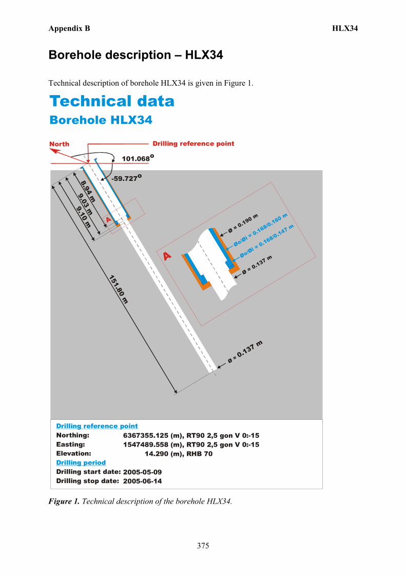
Appendix B HLX34
375
Borehole description – HLX34
Technical description of borehole HLX34 is given in Figure 1.
North
Technical dataBorehole HLX34
-59.727o
Ø = 0.137 m
151.80 m
9.10 m
Øo/Øi = 0.168/0.160 m
Ø = 0.190 m
Ø = 0.137 m
A
A
101.068o
6367355.125 (m),(m),
14.290 (m),
2005-05-092005-06-14
1547489.558 RT90 2,5 gon V 0:-15 RHB 70
RT90 2,5 gon V 0:-15Northing:Easting:Elevation:
Drilling start date:Drilling stop date:
Drilling reference point
Drilling period
Øo/Øi = 0.168/0.147 m
9.03 m8.94 m
Drilling reference point
Figure 1. Technical description of the borehole HLX34.

Appendix B HLX34
376
Deviation measurement in HLX34 The only deviation measurement performed in HLX34 was with the Mac/acc, Flexit instrument. The deviation logging activity is tabulated in Sicada Activity Log, see Table 1. Two Mag/acc measurements (ID 13142222 and 13138474) were executed down and up the borehole between the length 0 – 147.00 m, with the Flexit instrument. Corrections of measured data are shown in the File References (Sicada) for the measurements. The Mac/acc measurements (ID 13079714 and 13117400) are error marked measurements with adjusted bearing mainly in the first parts of the borehole. No geomagnetic disturbance exceeding 0.5 degrees was observed on the date and time of the Mag/acc measurements, see Figure 2.
Figure 2. The geomagnetic field was observed at the Observatory in Uppsala on 2005-07-20.
Borehole deviation multiple measurements. In the calculation of Borehole deviation multiple measurements (ID 13144025) the two Mag/acc measurements (ID 13142222 and 13138474) were used. Table 2 shows the deviation data for the calculation. A subset of the resulting deviation file for every approximately 20 m elevation (from Object_location) is shown in Table 3. The inclination and bearing uncertainties are calculated automatically, and based on these values the “Radius uncertainty” is calculated for every measuring level. Figure 3 show the resulting deviation data together with the other, not error marked, deviation activities listed in Table 1.
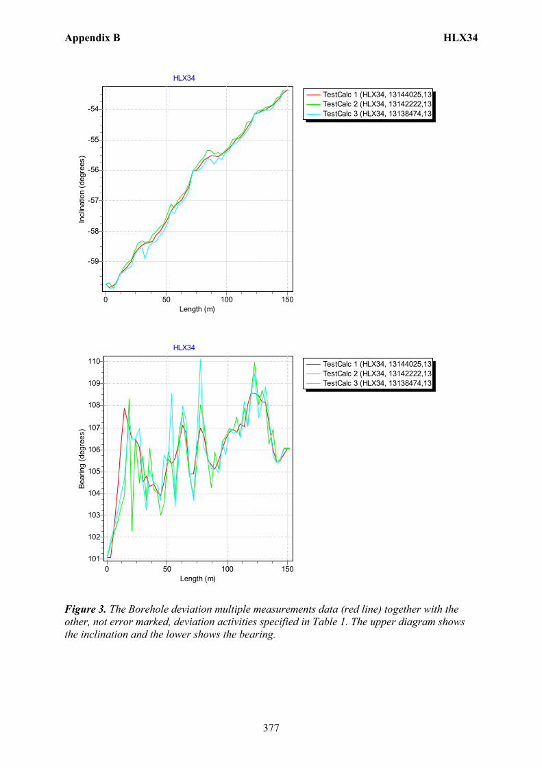
Appendix B HLX34
377
TestCalc 1 (HLX34, 13144025,13TestCalc 2 (HLX34, 13142222,13TestCalc 3 (HLX34, 13138474,13
HLX34
Length (m)150100500
Incl
inat
ion
(deg
rees
)
-54
-55
-56
-57
-58
-59
TestCalc 1 (HLX34, 13144025,13TestCalc 2 (HLX34, 13142222,13TestCalc 3 (HLX34, 13138474,13
HLX34
Length (m)150100500
Bear
ing
(deg
rees
)
110
109
108
107
106
105
104
103
102
101
Figure 3. The Borehole deviation multiple measurements data (red line) together with the other, not error marked, deviation activities specified in Table 1. The upper diagram shows the inclination and the lower shows the bearing.

Appendix B HLX34
378
Table 1. The deviation logging activities in Sicada for HLX34. Idcode Activity
Id Activity Type Code
Activity Start Date Secup (m)
Seclow (m)
Flags _Indat
HLX34 13142222 EG157 Magnetic - accelerometer measurement 2005-07-20 15:30 0.00 147.00 CF 070102 14:13 HLX34 13079714 EG157 Magnetic - accelerometer measurement 2005-07-20 15:30 0.00 147.00 EF 060707 11:35 HLX34 13117400 EG157 Magnetic - accelerometer measurement 2005-07-20 15:40 0.00 147.00 EF 070102 14:01 HLX34 13138474 EG157 Magnetic - accelerometer measurement 2005-07-20 16:00 0.00 147.00 CF 070104 14:23 HLX34 13144025 EG154 Borehole deviation multiple measurements 2007-01-04 15:00 I C 070215 16:17
Table 2. Content of the EG154-file. Idcode Deviation Activity Id Deviation Angle Type Approved Secup
(m) Approved Seclow (m)
Man Estim Angle Uncert (degrees)
HLX34 13138474 BEARING 18.00 147.00 HLX34 13138474 INCLINATION 3.00 147.00 HLX34 13142222 BEARING 18.00 147.00 HLX34 13142222 INCLINATION 3.00 147.00
Table 3. Subset (for every approx. 20 m elevation) of the resulting “Object_location” in Sicada. Idcode Northing
(m) Easting
(m) Elevation
(m) Length
(m) Elevation
Uncertainty Inclination (degrees)
Bearing (degrees)
Inclination Uncertainty
Bearing Uncertainty
Radius Uncertainty
HLX34 6367355.13 1547489.56 14.29 0.00 0.00 -59.73 101.07 0.2 1.7 0.00 HLX34 6367349.94 1547508.91 -19.16 39.00 0.06 -58.34 104.44 0.2 1.7 0.58 HLX34 6367346.57 1547521.32 -39.43 63.00 0.10 -56.95 107.10 0.2 1.7 0.96 HLX34 6367342.88 1547534.19 -59.34 87.00 0.14 -55.53 105.30 0.2 1.7 1.35 HLX34 6367339.06 1547547.30 -79.08 111.00 0.18 -54.91 107.18 0.2 1.7 1.74 HLX34 6367334.22 1547562.31 -100.99 138.00 0.23 -53.87 105.99 0.2 1.7 2.20 HLX34 6367332.00 1547570.19 -112.10 151.80 0.26 -53.37 106.06 0.2 1.7 2.44
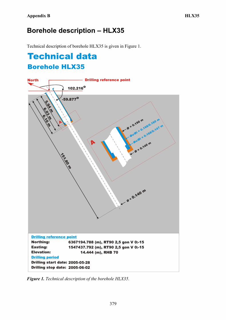
Appendix B HLX35
379
Borehole description – HLX35
Technical description of borehole HLX35 is given in Figure 1.
North
Technical dataBorehole HLX35
-59.877o
Ø = 0.140 m
151.80 m
6.10 m
Øo/Øi = 0.168/0.160 m
Ø = 0.190 m
Ø = 0.140 m
A
A
102.216o
6367194.788 (m),(m),
14.444 (m),
2005-05-282005-06-02
1547437.792 RT90 2,5 gon V 0:-15 RHB 70
RT90 2,5 gon V 0:-15Northing:Easting:Elevation:
Drilling start date:Drilling stop date:
Drilling reference point
Drilling period
Øo/Øi = 0.168/0.147 m
6.03 m5.94 m
Drilling reference point
Figure 1. Technical description of the borehole HLX35.
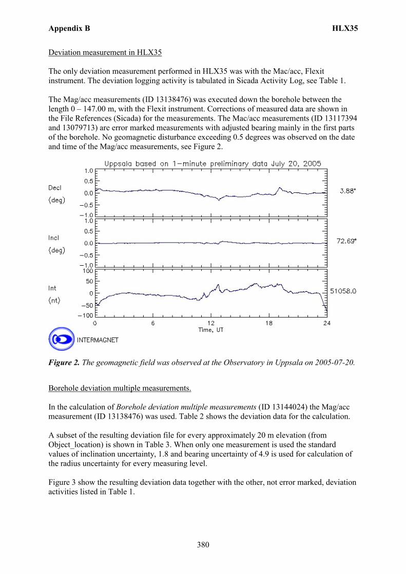
Appendix B HLX35
380
Deviation measurement in HLX35 The only deviation measurement performed in HLX35 was with the Mac/acc, Flexit instrument. The deviation logging activity is tabulated in Sicada Activity Log, see Table 1. The Mag/acc measurements (ID 13138476) was executed down the borehole between the length 0 – 147.00 m, with the Flexit instrument. Corrections of measured data are shown in the File References (Sicada) for the measurements. The Mac/acc measurements (ID 13117394 and 13079713) are error marked measurements with adjusted bearing mainly in the first parts of the borehole. No geomagnetic disturbance exceeding 0.5 degrees was observed on the date and time of the Mag/acc measurements, see Figure 2.
Figure 2. The geomagnetic field was observed at the Observatory in Uppsala on 2005-07-20.
Borehole deviation multiple measurements. In the calculation of Borehole deviation multiple measurements (ID 13144024) the Mag/acc measurement (ID 13138476) was used. Table 2 shows the deviation data for the calculation. A subset of the resulting deviation file for every approximately 20 m elevation (from Object_location) is shown in Table 3. When only one measurement is used the standard values of inclination uncertainty, 1.8 and bearing uncertainty of 4.9 is used for calculation of the radius uncertainty for every measuring level. Figure 3 show the resulting deviation data together with the other, not error marked, deviation activities listed in Table 1.
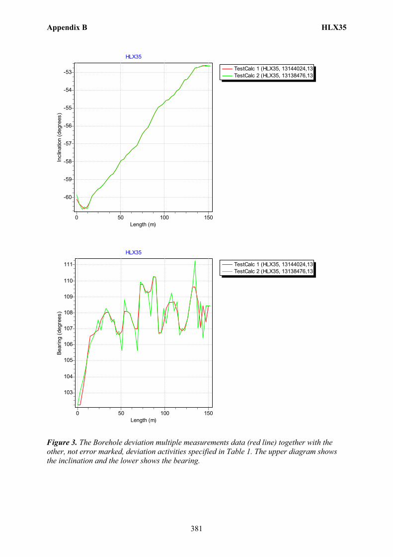
Appendix B HLX35
381
TestCalc 1 (HLX35, 13144024,13TestCalc 2 (HLX35, 13138476,13
HLX35
Length (m)150100500
Incl
inat
ion
(deg
rees
)
-53
-54
-55
-56
-57
-58
-59
-60
TestCalc 1 (HLX35, 13144024,13TestCalc 2 (HLX35, 13138476,13
HLX35
Length (m)150100500
Bear
ing
(deg
rees
)
111
110
109
108
107
106
105
104
103
Figure 3. The Borehole deviation multiple measurements data (red line) together with the other, not error marked, deviation activities specified in Table 1. The upper diagram shows the inclination and the lower shows the bearing.
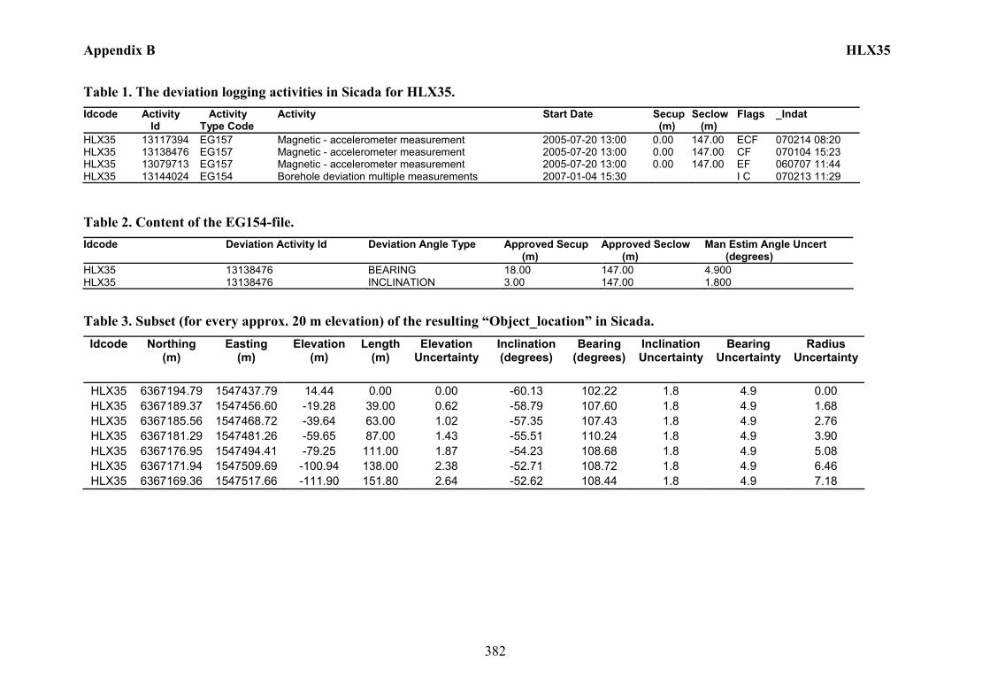
Appendix B HLX35
382
Table 1. The deviation logging activities in Sicada for HLX35. Idcode Activity
Id Activity Type Code
Activity Start Date Secup (m)
Seclow (m)
Flags _Indat
HLX35 13117394 EG157 Magnetic - accelerometer measurement 2005-07-20 13:00 0.00 147.00 ECF 070214 08:20 HLX35 13138476 EG157 Magnetic - accelerometer measurement 2005-07-20 13:00 0.00 147.00 CF 070104 15:23 HLX35 13079713 EG157 Magnetic - accelerometer measurement 2005-07-20 13:00 0.00 147.00 EF 060707 11:44 HLX35 13144024 EG154 Borehole deviation multiple measurements 2007-01-04 15:30 I C 070213 11:29
Table 2. Content of the EG154-file. Idcode Deviation Activity Id Deviation Angle Type Approved Secup
(m) Approved Seclow (m)
Man Estim Angle Uncert (degrees)
HLX35 13138476 BEARING 18.00 147.00 4.900 HLX35 13138476 INCLINATION 3.00 147.00 1.800
Table 3. Subset (for every approx. 20 m elevation) of the resulting “Object_location” in Sicada. Idcode Northing
(m) Easting
(m) Elevation
(m) Length
(m) Elevation
Uncertainty Inclination (degrees)
Bearing (degrees)
Inclination Uncertainty
Bearing Uncertainty
Radius Uncertainty
HLX35 6367194.79 1547437.79 14.44 0.00 0.00 -60.13 102.22 1.8 4.9 0.00 HLX35 6367189.37 1547456.60 -19.28 39.00 0.62 -58.79 107.60 1.8 4.9 1.68 HLX35 6367185.56 1547468.72 -39.64 63.00 1.02 -57.35 107.43 1.8 4.9 2.76 HLX35 6367181.29 1547481.26 -59.65 87.00 1.43 -55.51 110.24 1.8 4.9 3.90 HLX35 6367176.95 1547494.41 -79.25 111.00 1.87 -54.23 108.68 1.8 4.9 5.08 HLX35 6367171.94 1547509.69 -100.94 138.00 2.38 -52.71 108.72 1.8 4.9 6.46 HLX35 6367169.36 1547517.66 -111.90 151.80 2.64 -52.62 108.44 1.8 4.9 7.18
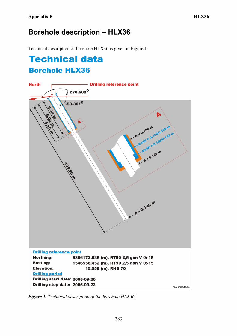
Appendix B HLX36
383
Borehole description – HLX36
Technical description of borehole HLX36 is given in Figure 1.
North
Technical dataBorehole HLX36
-59.301o
Ø = 0.140 m
199.80 m
6.10 m
Øo/Øi = 0.168/0.160 m
Ø = 0.190 m
Ø = 0.140 m
AA
270.608o
6366172.935 (m),(m),
15.558 (m),
2005-09-202005-09-22
1546558.452 RT90 2,5 gon V 0:-15 RHB 70
RT90 2,5 gon V 0:-15Northing:Easting:Elevation:
Drilling start date:Drilling stop date:
Drilling reference point
Drilling period
Øo/Øi = 0.168/0.142 m
6.03 m5.94 m
Drilling reference point
Rev 2005-11-24
Figure 1. Technical description of the borehole HLX36.
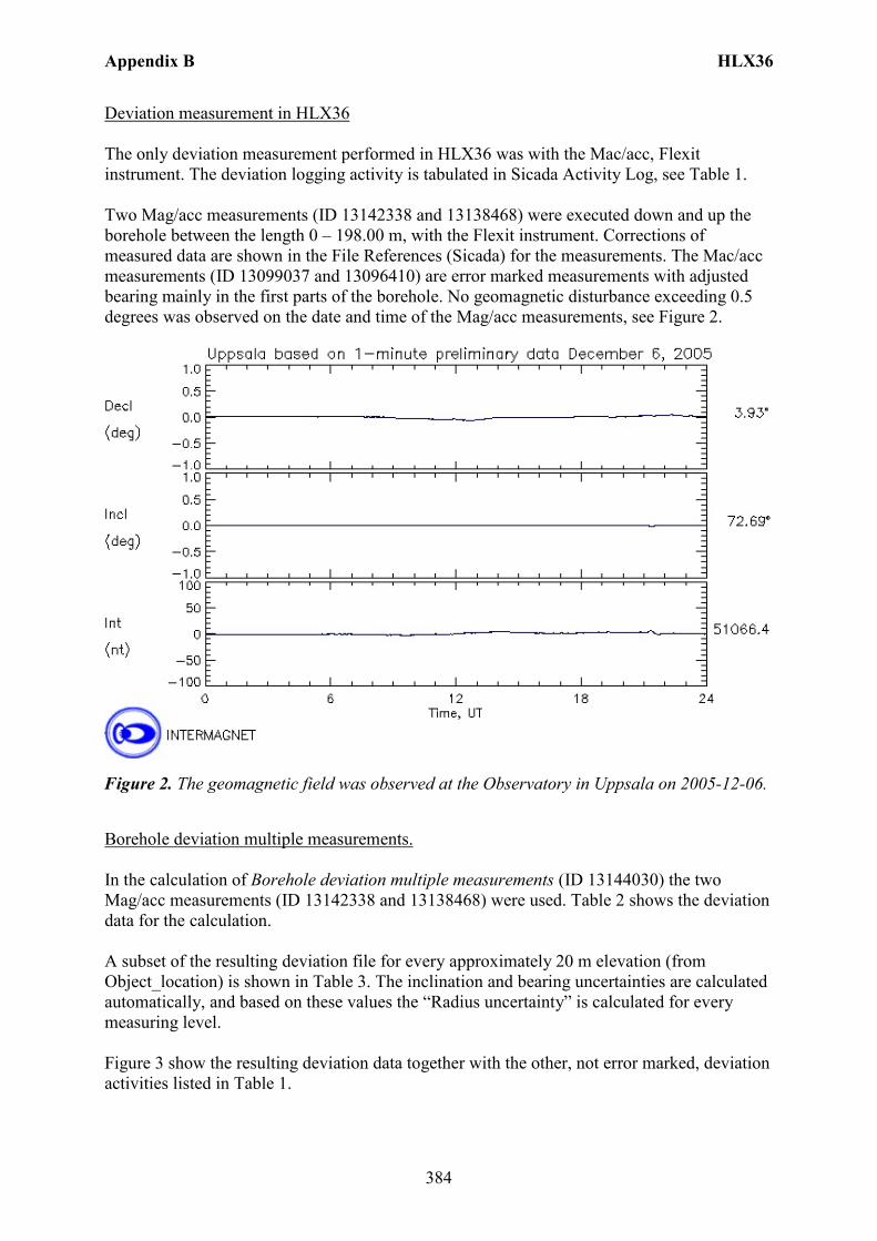
Appendix B HLX36
384
Deviation measurement in HLX36 The only deviation measurement performed in HLX36 was with the Mac/acc, Flexit instrument. The deviation logging activity is tabulated in Sicada Activity Log, see Table 1. Two Mag/acc measurements (ID 13142338 and 13138468) were executed down and up the borehole between the length 0 – 198.00 m, with the Flexit instrument. Corrections of measured data are shown in the File References (Sicada) for the measurements. The Mac/acc measurements (ID 13099037 and 13096410) are error marked measurements with adjusted bearing mainly in the first parts of the borehole. No geomagnetic disturbance exceeding 0.5 degrees was observed on the date and time of the Mag/acc measurements, see Figure 2.
Figure 2. The geomagnetic field was observed at the Observatory in Uppsala on 2005-12-06.
Borehole deviation multiple measurements. In the calculation of Borehole deviation multiple measurements (ID 13144030) the two Mag/acc measurements (ID 13142338 and 13138468) were used. Table 2 shows the deviation data for the calculation. A subset of the resulting deviation file for every approximately 20 m elevation (from Object_location) is shown in Table 3. The inclination and bearing uncertainties are calculated automatically, and based on these values the “Radius uncertainty” is calculated for every measuring level. Figure 3 show the resulting deviation data together with the other, not error marked, deviation activities listed in Table 1.
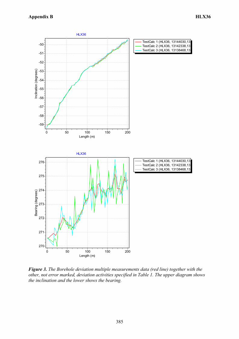
Appendix B HLX36
385
TestCalc 1 (HLX36, 13144030,13TestCalc 2 (HLX36, 13142338,13TestCalc 3 (HLX36, 13138468,13
HLX36
Length (m)200150100500
Incl
inat
ion
(deg
rees
)
-50
-51
-52
-53
-54
-55
-56
-57
-58
-59
TestCalc 1 (HLX36, 13144030,13TestCalc 2 (HLX36, 13142338,13TestCalc 3 (HLX36, 13138468,13
HLX36
Length (m)200150100500
Bear
ing
(deg
rees
)
276
275
274
273
272
271
270
Figure 3. The Borehole deviation multiple measurements data (red line) together with the other, not error marked, deviation activities specified in Table 1. The upper diagram shows the inclination and the lower shows the bearing.
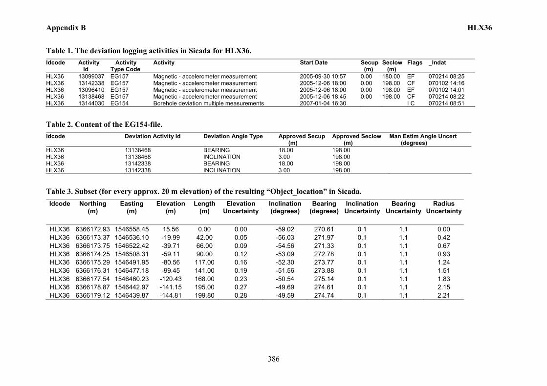
Appendix B HLX36
386
Table 1. The deviation logging activities in Sicada for HLX36. Idcode Activity
Id Activity Type Code
Activity Start Date Secup (m)
Seclow (m)
Flags _Indat
HLX36 13099037 EG157 Magnetic - accelerometer measurement 2005-09-30 10:57 0.00 180.00 EF 070214 08:25 HLX36 13142338 EG157 Magnetic - accelerometer measurement 2005-12-06 18:00 0.00 198.00 CF 070102 14:16 HLX36 13096410 EG157 Magnetic - accelerometer measurement 2005-12-06 18:00 0.00 198.00 EF 070102 14:01 HLX36 13138468 EG157 Magnetic - accelerometer measurement 2005-12-06 18:45 0.00 198.00 CF 070214 08:22 HLX36 13144030 EG154 Borehole deviation multiple measurements 2007-01-04 16:30 I C 070214 08:51
Table 2. Content of the EG154-file. Idcode Deviation Activity Id Deviation Angle Type Approved Secup
(m) Approved Seclow (m)
Man Estim Angle Uncert (degrees)
HLX36 13138468 BEARING 18.00 198.00 HLX36 13138468 INCLINATION 3.00 198.00 HLX36 13142338 BEARING 18.00 198.00 HLX36 13142338 INCLINATION 3.00 198.00
Table 3. Subset (for every approx. 20 m elevation) of the resulting “Object_location” in Sicada. Idcode Northing
(m) Easting
(m) Elevation
(m) Length
(m) Elevation
Uncertainty Inclination (degrees)
Bearing (degrees)
Inclination Uncertainty
Bearing Uncertainty
Radius Uncertainty
HLX36 6366172.93 1546558.45 15.56 0.00 0.00 -59.02 270.61 0.1 1.1 0.00 HLX36 6366173.37 1546536.10 -19.99 42.00 0.05 -56.03 271.97 0.1 1.1 0.42 HLX36 6366173.75 1546522.42 -39.71 66.00 0.09 -54.56 271.33 0.1 1.1 0.67 HLX36 6366174.25 1546508.31 -59.11 90.00 0.12 -53.09 272.78 0.1 1.1 0.93 HLX36 6366175.29 1546491.95 -80.56 117.00 0.16 -52.30 273.77 0.1 1.1 1.24 HLX36 6366176.31 1546477.18 -99.45 141.00 0.19 -51.56 273.88 0.1 1.1 1.51 HLX36 6366177.54 1546460.23 -120.43 168.00 0.23 -50.54 275.14 0.1 1.1 1.83 HLX36 6366178.87 1546442.97 -141.15 195.00 0.27 -49.69 274.61 0.1 1.1 2.15 HLX36 6366179.12 1546439.87 -144.81 199.80 0.28 -49.59 274.74 0.1 1.1 2.21
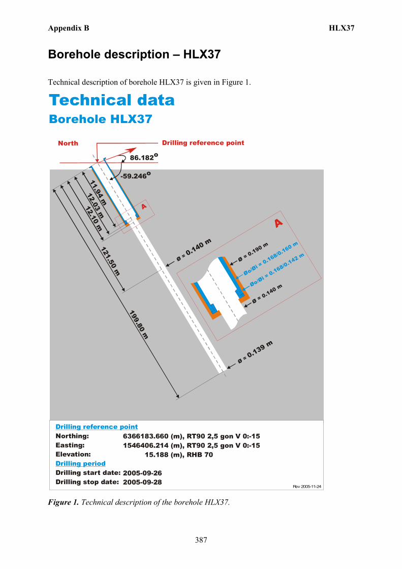
Appendix B HLX37
387
Borehole description – HLX37
Technical description of borehole HLX37 is given in Figure 1.
North
Technical dataBorehole HLX37
-59.246o
Ø = 0.139 m
121.50 m
12.10 m
Øo/Øi = 0.168/0.160 m
Ø = 0.190 m
Ø = 0.140 m
A
A
86.182o
6366183.660 (m),(m),
15.188 (m),
2005-09-262005-09-28
1546406.214 RT90 2,5 gon V 0:-15 RHB 70
RT90 2,5 gon V 0:-15Northing:Easting:Elevation:
Drilling start date:Drilling stop date:
Drilling reference point
Drilling period
Øo/Øi = 0.168/0.142 m
12.03 m11.94 m
Drilling reference point
199.80 mØ = 0.140 m
Rev 2005-11-24
Figure 1. Technical description of the borehole HLX37.

Appendix B HLX37
388
Deviation measurement in HLX37 The only deviation measurement performed in HLX37 was with the Mac/acc, Flexit instrument. The deviation logging activity is tabulated in Sicada Activity Log, see Table 1. Two Mag/acc measurements (ID 13142339 and 13138469) were executed down and up the borehole between the length 0 – 198.00 m, with the Flexit instrument. Corrections of measured data are shown in the File References (Sicada) for the measurements. The Mac/acc measurements (ID 13117395 and 13096407) are error marked measurements with adjusted bearing mainly in the first parts of the borehole. No geomagnetic disturbance exceeding 0.5 degrees was observed on the date and time of the Mag/acc measurements, see Figure 2.
Figure 2. The geomagnetic field was observed at the Observatory in Uppsala on 2005-12-07.
Borehole deviation multiple measurements. In the calculation of Borehole deviation multiple measurements (ID 13144031) the two Mag/acc measurements (ID 13142339 and 13138469) were used. Table 2 shows the deviation data for the calculation. A subset of the resulting deviation file for every approximately 20 m elevation (from Object_location) is shown in Table 3. The inclination and bearing uncertainties are calculated automatically, and based on these values the “Radius uncertainty” is calculated for every measuring level. Figure 3 show the resulting deviation data together with the other, not error marked, deviation activities listed in Table 1.
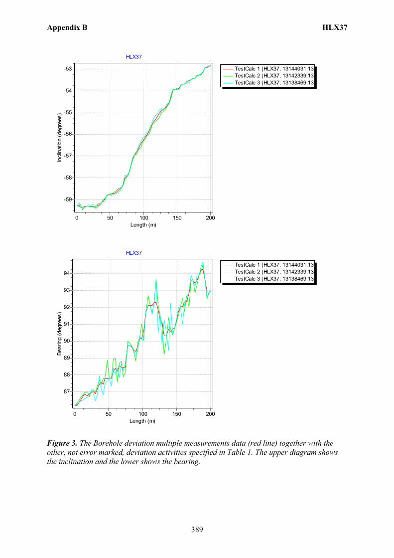
Appendix B HLX37
389
TestCalc 1 (HLX37, 13144031,13TestCalc 2 (HLX37, 13142339,13TestCalc 3 (HLX37, 13138469,13
HLX37
Length (m)200150100500
Incl
inat
ion
(deg
rees
)
-53
-54
-55
-56
-57
-58
-59
TestCalc 1 (HLX37, 13144031,13TestCalc 2 (HLX37, 13142339,13TestCalc 3 (HLX37, 13138469,13
HLX37
Length (m)200150100500
Bear
ing
(deg
rees
)
94
93
92
91
90
89
88
87
Figure 3. The Borehole deviation multiple measurements data (red line) together with the other, not error marked, deviation activities specified in Table 1. The upper diagram shows the inclination and the lower shows the bearing.

Appendix B HLX37
390
Table 1. The deviation logging activities in Sicada for HLX37. Idcode Activity
Id Activity Type Code
Activity Start Date Secup (m)
Seclow (m)
Flags _Indat
HLX37 13117395 EG157 Magnetic - accelerometer measurement 2005-09-30 09:20 0.00 180.00 EF 070102 14:01 HLX37 13142339 EG157 Magnetic - accelerometer measurement 2005-12-07 13:40 0.00 198.00 CF 070102 14:16 HLX37 13096407 EG157 Magnetic - accelerometer measurement 2005-12-07 13:40 0.00 198.00 EF 060707 11:43 HLX37 13138469 EG157 Magnetic - accelerometer measurement 2005-12-07 14:40 0.00 198.00 CF 070214 08:54 HLX37 13144031 EG154 Borehole deviation multiple measurements 2007-01-04 16:45 I C 070214 08:54
Table 2. Content of the EG154-file. Idcode Deviation Activity Id Deviation Angle Type Approved Secup
(m) Approved Seclow (m)
Man Estim Angle Uncert (degrees)
HLX37 13138469 BEARING 18.00 198.00 HLX37 13138469 INCLINATION 3.00 198.00 HLX37 13142339 BEARING 18.00 198.00 HLX37 13142339 INCLINATION 3.00 198.00
Table 3. Subset (for every approx. 20 m elevation) of the resulting “Object_location” in Sicada. Idcode Northing
(m) Easting
(m) Elevation
(m) Length
(m) Elevation
Uncertainty Inclination (degrees)
Bearing (degrees)
Inclination Uncertainty
Bearing Uncertainty
Radius Uncertainty
HLX37 6366183.66 1546406.21 15.19 0.00 0.00 -59.25 86.18 0.1 0.7 0.00 HLX37 6366184.83 1546427.65 -20.91 42.00 0.04 -58.97 87.49 0.1 0.7 0.26 HLX37 6366185.22 1546438.54 -38.86 63.00 0.06 -58.56 88.25 0.1 0.7 0.39 HLX37 6366185.44 1546451.30 -59.18 87.00 0.09 -56.94 89.47 0.1 0.7 0.55 HLX37 6366185.30 1546464.61 -79.15 111.00 0.12 -55.70 92.11 0.1 0.7 0.71 HLX37 6366184.93 1546478.34 -98.84 135.00 0.14 -54.66 90.32 0.1 0.7 0.88 HLX37 6366184.58 1546494.20 -120.68 162.00 0.17 -53.67 92.34 0.1 0.7 1.07 HLX37 6366183.75 1546508.47 -139.96 186.00 0.20 -53.25 94.24 0.1 0.7 1.25 HLX37 6366183.25 1546516.76 -150.98 199.80 0.22 -52.87 92.78 0.1 0.7 1.35
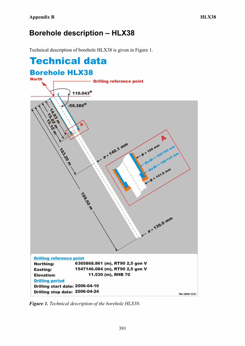
Appendix B HLX38
391
Borehole description – HLX38
Technical description of borehole HLX38 is given in Figure 1.
Technical dataBorehole HLX38
6365868.861 (m),1547146.084 (m), 11.530 (m),
2006-04-102006-04-24
RT90 2,5 gon V RHB 70
RT90 2,5 gon V
-59.389o
Ø = 139.0 mm
199.50 m
15.10 m
Øo/Øi = 168/160 mm
Ø = 190 mm
Ø = 141.0 mm
A
A
Northing:Easting:Elevation:
Drilling start date:Drilling stop date:
Drilling reference point
Drilling period
Øo/Øi = 168/143 mm
15.02 m14.93 m
Drilling reference point
110.043o
Ø = 140.1 mm103.20 m
North
Rev 2006-12-21Rev 2006-12-21
Figure 1. Technical description of the borehole HLX38.

Appendix B HLX38
392
Deviation measurement in HLX38 The only deviation measurement performed in HLX38 was with the Mac/acc, Flexit instrument. The deviation logging activity is tabulated in Sicada Activity Log, see Table 1. Two Mag/acc measurements (ID 13142350 and 13138441) were executed down and up the borehole between the length 0 – 198.00 m, with the Flexit instrument. Corrections of measured data are shown in the File References (Sicada) for the measurements. The Mac/acc measurement (ID 13115950) is error marked measurement with adjusted bearing mainly in the first part of the borehole. No geomagnetic disturbance exceeding 0.5 degrees was observed on the date and time of the Mag/acc measurements, see Figure 2.
Figure 2. The geomagnetic field was observed at the Observatory in Uppsala on 2006-05-14.
Borehole deviation multiple measurements. In the calculation of Borehole deviation multiple measurements (ID 13144029) the two Mag/acc measurements (ID 13142350 and 13138441) were used. Table 2 shows the deviation data for the calculation. A subset of the resulting deviation file for every approximately 20 m elevation (from Object_location) is shown in Table 3. The inclination and bearing uncertainties are calculated automatically, and based on these values the “Radius uncertainty” is calculated for every measuring level. Figure 3 show the resulting deviation data together with the other, not error marked, deviation activities listed in Table 1.
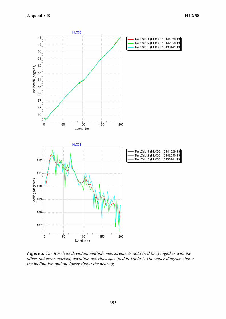
Appendix B HLX38
393
TestCalc 1 (HLX38, 13144029,13TestCalc 2 (HLX38, 13142350,13TestCalc 3 (HLX38, 13138441,13
HLX38
Length (m)200150100500
Incl
inat
ion
(deg
rees
)-48
-49
-50
-51
-52
-53
-54
-55
-56
-57
-58
-59
TestCalc 1 (HLX38, 13144029,13TestCalc 2 (HLX38, 13142350,13TestCalc 3 (HLX38, 13138441,13
HLX38
Length (m)200150100500
Bear
ing
(deg
rees
)
112
111
110
109
108
107
Figure 3. The Borehole deviation multiple measurements data (red line) together with the other, not error marked, deviation activities specified in Table 1. The upper diagram shows the inclination and the lower shows the bearing.
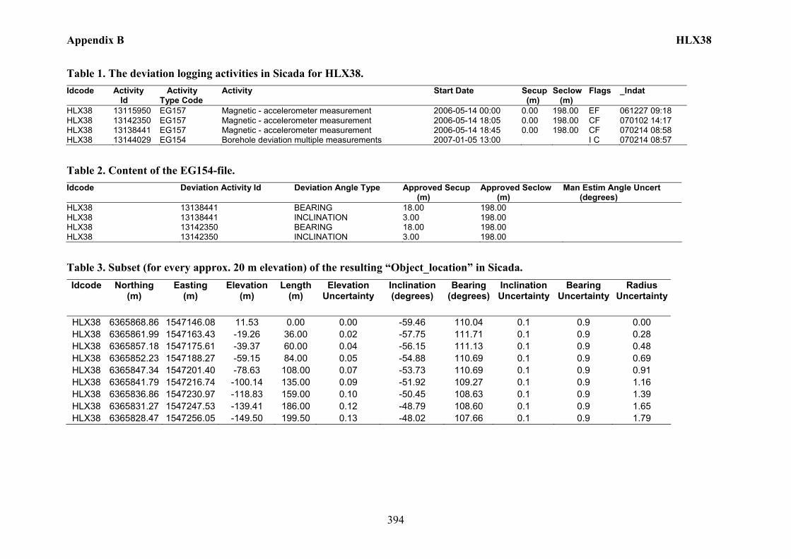
Appendix B HLX38
394
Table 1. The deviation logging activities in Sicada for HLX38. Idcode Activity
Id Activity Type Code
Activity Start Date Secup (m)
Seclow (m)
Flags _Indat
HLX38 13115950 EG157 Magnetic - accelerometer measurement 2006-05-14 00:00 0.00 198.00 EF 061227 09:18 HLX38 13142350 EG157 Magnetic - accelerometer measurement 2006-05-14 18:05 0.00 198.00 CF 070102 14:17 HLX38 13138441 EG157 Magnetic - accelerometer measurement 2006-05-14 18:45 0.00 198.00 CF 070214 08:58 HLX38 13144029 EG154 Borehole deviation multiple measurements 2007-01-05 13:00 I C 070214 08:57
Table 2. Content of the EG154-file. Idcode Deviation Activity Id Deviation Angle Type Approved Secup
(m) Approved Seclow (m)
Man Estim Angle Uncert (degrees)
HLX38 13138441 BEARING 18.00 198.00 HLX38 13138441 INCLINATION 3.00 198.00 HLX38 13142350 BEARING 18.00 198.00 HLX38 13142350 INCLINATION 3.00 198.00
Table 3. Subset (for every approx. 20 m elevation) of the resulting “Object_location” in Sicada. Idcode Northing
(m) Easting
(m) Elevation
(m) Length
(m) Elevation
Uncertainty Inclination (degrees)
Bearing (degrees)
Inclination Uncertainty
Bearing Uncertainty
Radius Uncertainty
HLX38 6365868.86 1547146.08 11.53 0.00 0.00 -59.46 110.04 0.1 0.9 0.00 HLX38 6365861.99 1547163.43 -19.26 36.00 0.02 -57.75 111.71 0.1 0.9 0.28 HLX38 6365857.18 1547175.61 -39.37 60.00 0.04 -56.15 111.13 0.1 0.9 0.48 HLX38 6365852.23 1547188.27 -59.15 84.00 0.05 -54.88 110.69 0.1 0.9 0.69 HLX38 6365847.34 1547201.40 -78.63 108.00 0.07 -53.73 110.69 0.1 0.9 0.91 HLX38 6365841.79 1547216.74 -100.14 135.00 0.09 -51.92 109.27 0.1 0.9 1.16 HLX38 6365836.86 1547230.97 -118.83 159.00 0.10 -50.45 108.63 0.1 0.9 1.39 HLX38 6365831.27 1547247.53 -139.41 186.00 0.12 -48.79 108.60 0.1 0.9 1.65 HLX38 6365828.47 1547256.05 -149.50 199.50 0.13 -48.02 107.66 0.1 0.9 1.79

Appendix B HLX39
395
Borehole description – HLX39
Technical description of borehole HLX39 is given in Figure 1.
North
Technical dataBorehole HLX39
6366887.869 (m),1546880.479 (m), 27.044 (m),
2006-06-072006-06-14
RT90 2,5 gon V RHB 70
RT90 2,5 gon V
-59.348o
Ø = 137.9 mm
199.30 m
6.10 m
Øo/Øi = 168/160 mm
Ø = 190 mm
Ø = 139.0 mm
A
A
Northing:Easting:Elevation:
Drilling start date:Drilling stop date:
Drilling reference point
Drilling period
Øo/Øi = 168/143 m
m
6.02 m5.93 m
Drilling reference point
14.291o
Ø = 138.4 mm
121.00 m
Rev 2006-12-21
Figure 1. Technical description of the borehole HLX39.
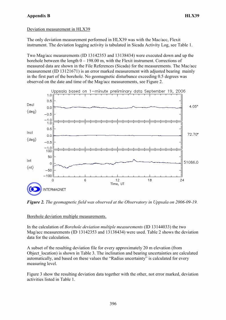
Appendix B HLX39
396
Deviation measurement in HLX39 The only deviation measurement performed in HLX39 was with the Mac/acc, Flexit instrument. The deviation logging activity is tabulated in Sicada Activity Log, see Table 1. Two Mag/acc measurements (ID 13142353 and 13138434) were executed down and up the borehole between the length 0 – 198.00 m, with the Flexit instrument. Corrections of measured data are shown in the File References (Sicada) for the measurements. The Mac/acc measurement (ID 13121671) is an error marked measurement with adjusted bearing mainly in the first part of the borehole. No geomagnetic disturbance exceeding 0.5 degrees was observed on the date and time of the Mag/acc measurements, see Figure 2.
Figure 2. The geomagnetic field was observed at the Observatory in Uppsala on 2006-09-19.
Borehole deviation multiple measurements. In the calculation of Borehole deviation multiple measurements (ID 13144033) the two Mag/acc measurements (ID 13142353 and 13138434) were used. Table 2 shows the deviation data for the calculation. A subset of the resulting deviation file for every approximately 20 m elevation (from Object_location) is shown in Table 3. The inclination and bearing uncertainties are calculated automatically, and based on these values the “Radius uncertainty” is calculated for every measuring level. Figure 3 show the resulting deviation data together with the other, not error marked, deviation activities listed in Table 1.
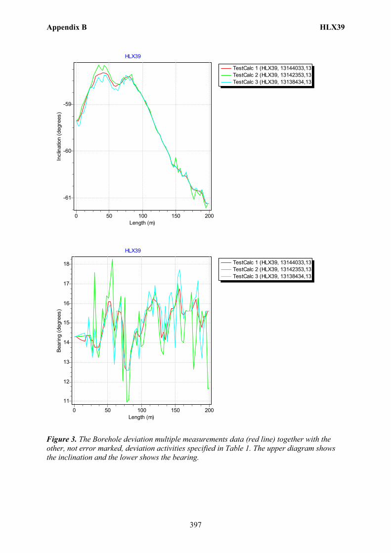
Appendix B HLX39
397
TestCalc 1 (HLX39, 13144033,13TestCalc 2 (HLX39, 13142353,13TestCalc 3 (HLX39, 13138434,13
HLX39
Length (m)200150100500
Incl
inat
ion
(deg
rees
)
-59
-60
-61
TestCalc 1 (HLX39, 13144033,13TestCalc 2 (HLX39, 13142353,13TestCalc 3 (HLX39, 13138434,13
HLX39
Length (m)200150100500
Bear
ing
(deg
rees
)
18
17
16
15
14
13
12
11
Figure 3. The Borehole deviation multiple measurements data (red line) together with the other, not error marked, deviation activities specified in Table 1. The upper diagram shows the inclination and the lower shows the bearing.
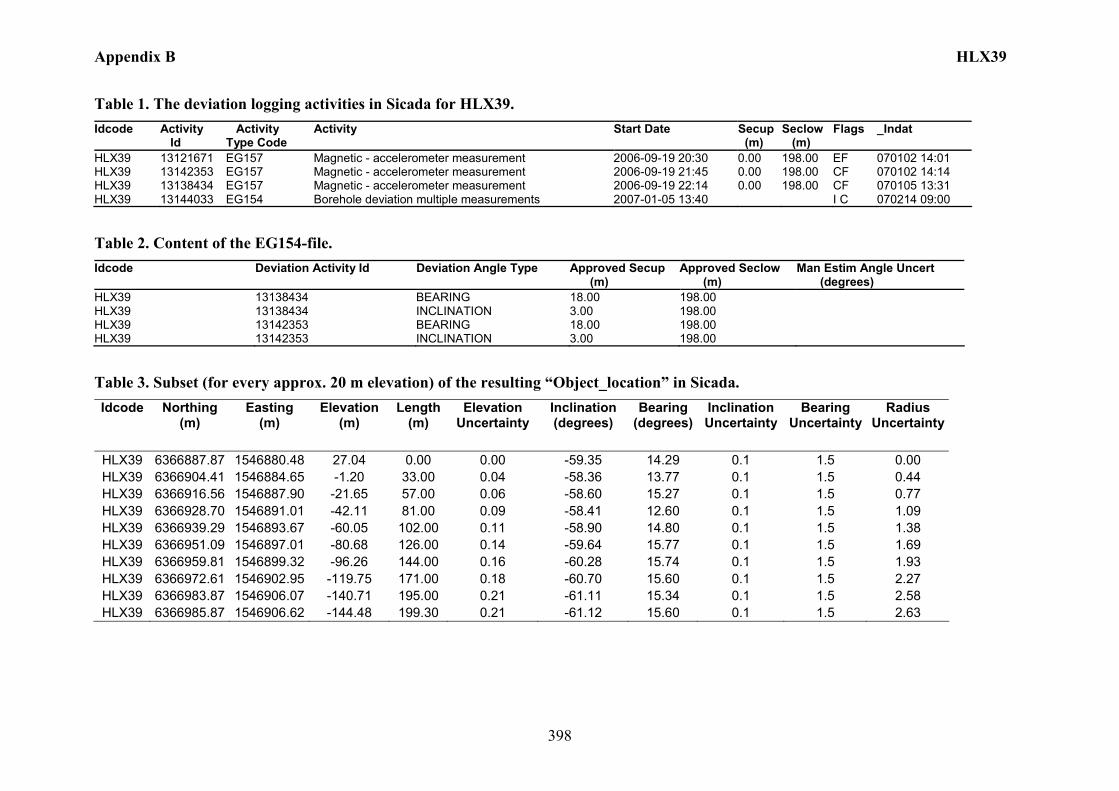
Appendix B HLX39
398
Table 1. The deviation logging activities in Sicada for HLX39. Idcode Activity
Id Activity Type Code
Activity Start Date Secup (m)
Seclow (m)
Flags _Indat
HLX39 13121671 EG157 Magnetic - accelerometer measurement 2006-09-19 20:30 0.00 198.00 EF 070102 14:01 HLX39 13142353 EG157 Magnetic - accelerometer measurement 2006-09-19 21:45 0.00 198.00 CF 070102 14:14 HLX39 13138434 EG157 Magnetic - accelerometer measurement 2006-09-19 22:14 0.00 198.00 CF 070105 13:31 HLX39 13144033 EG154 Borehole deviation multiple measurements 2007-01-05 13:40 I C 070214 09:00
Table 2. Content of the EG154-file. Idcode Deviation Activity Id Deviation Angle Type Approved Secup
(m) Approved Seclow (m)
Man Estim Angle Uncert (degrees)
HLX39 13138434 BEARING 18.00 198.00 HLX39 13138434 INCLINATION 3.00 198.00 HLX39 13142353 BEARING 18.00 198.00 HLX39 13142353 INCLINATION 3.00 198.00
Table 3. Subset (for every approx. 20 m elevation) of the resulting “Object_location” in Sicada. Idcode Northing
(m) Easting
(m) Elevation
(m) Length
(m) Elevation
Uncertainty Inclination (degrees)
Bearing (degrees)
Inclination Uncertainty
Bearing Uncertainty
Radius Uncertainty
HLX39 6366887.87 1546880.48 27.04 0.00 0.00 -59.35 14.29 0.1 1.5 0.00 HLX39 6366904.41 1546884.65 -1.20 33.00 0.04 -58.36 13.77 0.1 1.5 0.44 HLX39 6366916.56 1546887.90 -21.65 57.00 0.06 -58.60 15.27 0.1 1.5 0.77 HLX39 6366928.70 1546891.01 -42.11 81.00 0.09 -58.41 12.60 0.1 1.5 1.09 HLX39 6366939.29 1546893.67 -60.05 102.00 0.11 -58.90 14.80 0.1 1.5 1.38 HLX39 6366951.09 1546897.01 -80.68 126.00 0.14 -59.64 15.77 0.1 1.5 1.69 HLX39 6366959.81 1546899.32 -96.26 144.00 0.16 -60.28 15.74 0.1 1.5 1.93 HLX39 6366972.61 1546902.95 -119.75 171.00 0.18 -60.70 15.60 0.1 1.5 2.27 HLX39 6366983.87 1546906.07 -140.71 195.00 0.21 -61.11 15.34 0.1 1.5 2.58 HLX39 6366985.87 1546906.62 -144.48 199.30 0.21 -61.12 15.60 0.1 1.5 2.63
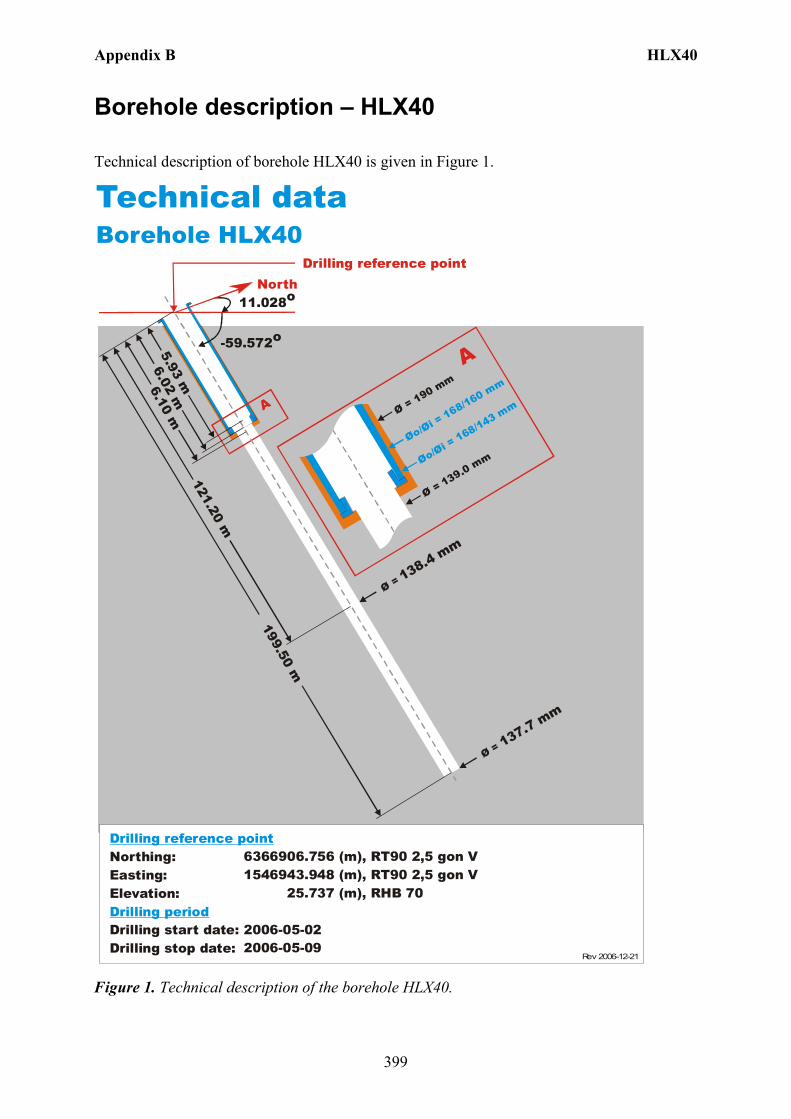
Appendix B HLX40
399
Borehole description – HLX40
Technical description of borehole HLX40 is given in Figure 1.
North
Technical dataBorehole HLX40
6366906.756 (m),1546943.948 (m), 25.737 (m),
2006-05-022006-05-09
RT90 2,5 gon V RHB 70
RT90 2,5 gon V
-59.572o
Ø = 137.7 mm
199.50 m
6.10 m
Øo/Øi = 168/160 mm
Ø = 190 mm
Ø = 139.0 mm
A
A
Northing:Easting:Elevation:
Drilling start date:Drilling stop date:
Drilling reference point
Drilling period
Øo/Øi = 168/143 m
m
6.02 m5.93 m
Drilling reference point
11.028o
Ø = 138.4 mm
121.20 m
Rev 2006-12-21
Figure 1. Technical description of the borehole HLX40.
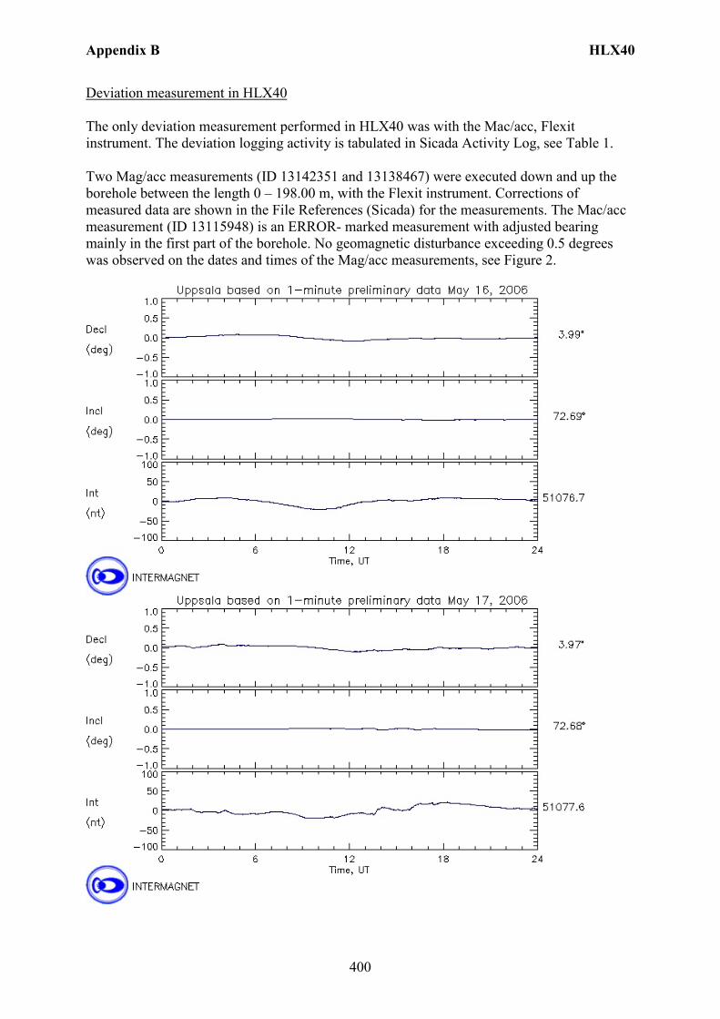
Appendix B HLX40
400
Deviation measurement in HLX40 The only deviation measurement performed in HLX40 was with the Mac/acc, Flexit instrument. The deviation logging activity is tabulated in Sicada Activity Log, see Table 1. Two Mag/acc measurements (ID 13142351 and 13138467) were executed down and up the borehole between the length 0 – 198.00 m, with the Flexit instrument. Corrections of measured data are shown in the File References (Sicada) for the measurements. The Mac/acc measurement (ID 13115948) is an ERROR- marked measurement with adjusted bearing mainly in the first part of the borehole. No geomagnetic disturbance exceeding 0.5 degrees was observed on the dates and times of the Mag/acc measurements, see Figure 2.
Appendix B HLX40
401
Figure 2. The geomagnetic field was observed at the Observatory in Uppsala on 2006-05-16 and 2006-05-17.
Borehole deviation multiple measurements. In the calculation of Borehole deviation multiple measurements (ID 13144028) the two Mag/acc measurements (ID 13142351 and 13138467) were used. Table 2 shows the deviation data for the calculation. A subset of the resulting deviation file for every approximately 20 m elevation (from Object_location) is shown in Table 3. The inclination and bearing uncertainties are calculated automatically, and based on these values the “Radius uncertainty” is calculated for every measuring level. Figure 3 show the resulting deviation data together with the other, not ERROR- marked, deviation activities listed in Table 1.
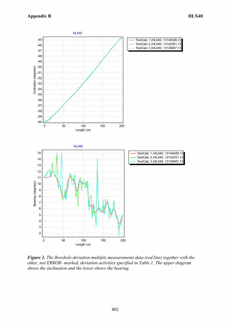
Appendix B HLX40
402
TestCalc 1 (HLX40, 13144028,13TestCalc 2 (HLX40, 13142351,13TestCalc 3 (HLX40, 13138467,13
HLX40
Length (m)200150100500
Incl
inat
ion
(deg
rees
)
-45
-46
-47
-48
-49
-50
-51
-52
-53
-54
-55
-56
-57
-58
-59
-60
TestCalc 1 (HLX40, 13144028,13TestCalc 2 (HLX40, 13142351,13TestCalc 3 (HLX40, 13138467,13
HLX40
Length (m)200150100500
Bear
ing
(deg
rees
)
15
14
13
12
11
10
9
8
7
6
5
4
3
2
Figure 3. The Borehole deviation multiple measurements data (red line) together with the other, not ERROR- marked, deviation activities specified in Table 1. The upper diagram shows the inclination and the lower shows the bearing.
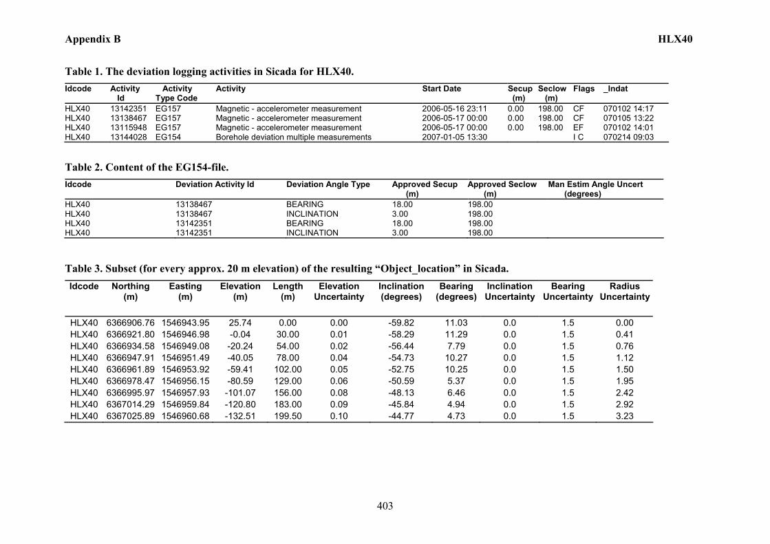
Appendix B HLX40
403
Table 1. The deviation logging activities in Sicada for HLX40. Idcode Activity
Id Activity Type Code
Activity Start Date Secup (m)
Seclow (m)
Flags _Indat
HLX40 13142351 EG157 Magnetic - accelerometer measurement 2006-05-16 23:11 0.00 198.00 CF 070102 14:17 HLX40 13138467 EG157 Magnetic - accelerometer measurement 2006-05-17 00:00 0.00 198.00 CF 070105 13:22 HLX40 13115948 EG157 Magnetic - accelerometer measurement 2006-05-17 00:00 0.00 198.00 EF 070102 14:01 HLX40 13144028 EG154 Borehole deviation multiple measurements 2007-01-05 13:30 I C 070214 09:03
Table 2. Content of the EG154-file. Idcode Deviation Activity Id Deviation Angle Type Approved Secup
(m) Approved Seclow (m)
Man Estim Angle Uncert (degrees)
HLX40 13138467 BEARING 18.00 198.00 HLX40 13138467 INCLINATION 3.00 198.00 HLX40 13142351 BEARING 18.00 198.00 HLX40 13142351 INCLINATION 3.00 198.00
Table 3. Subset (for every approx. 20 m elevation) of the resulting “Object_location” in Sicada. Idcode Northing
(m) Easting
(m) Elevation
(m) Length
(m) Elevation
Uncertainty Inclination (degrees)
Bearing (degrees)
Inclination Uncertainty
Bearing Uncertainty
Radius Uncertainty
HLX40 6366906.76 1546943.95 25.74 0.00 0.00 -59.82 11.03 0.0 1.5 0.00 HLX40 6366921.80 1546946.98 -0.04 30.00 0.01 -58.29 11.29 0.0 1.5 0.41 HLX40 6366934.58 1546949.08 -20.24 54.00 0.02 -56.44 7.79 0.0 1.5 0.76 HLX40 6366947.91 1546951.49 -40.05 78.00 0.04 -54.73 10.27 0.0 1.5 1.12 HLX40 6366961.89 1546953.92 -59.41 102.00 0.05 -52.75 10.25 0.0 1.5 1.50 HLX40 6366978.47 1546956.15 -80.59 129.00 0.06 -50.59 5.37 0.0 1.5 1.95 HLX40 6366995.97 1546957.93 -101.07 156.00 0.08 -48.13 6.46 0.0 1.5 2.42 HLX40 6367014.29 1546959.84 -120.80 183.00 0.09 -45.84 4.94 0.0 1.5 2.92 HLX40 6367025.89 1546960.68 -132.51 199.50 0.10 -44.77 4.73 0.0 1.5 3.23
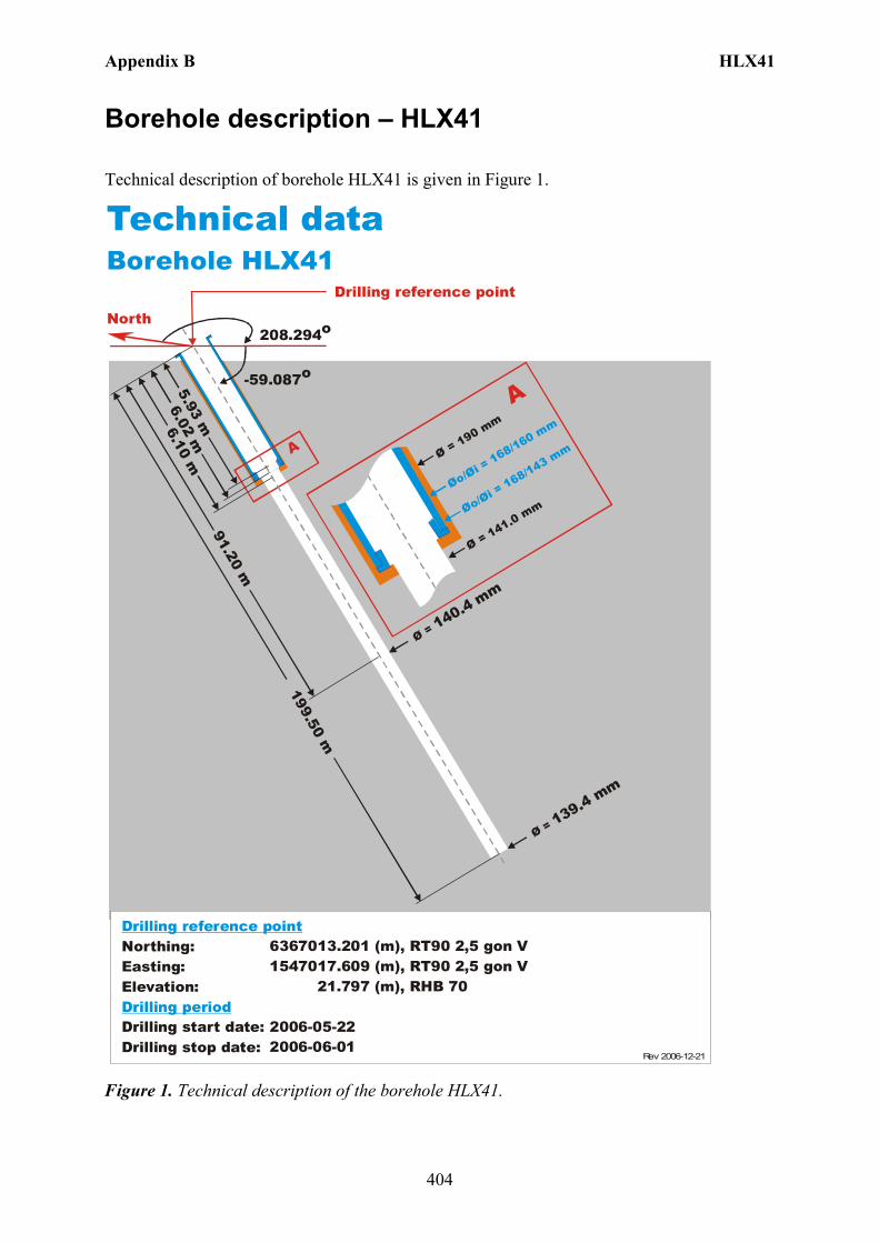
Appendix B HLX41
404
Borehole description – HLX41
Technical description of borehole HLX41 is given in Figure 1.
Technical dataBorehole HLX41
6367013.201 (m),1547017.609 (m), 21.797 (m),
2006-05-222006-06-01
RT90 2,5 gon V RHB 70
RT90 2,5 gon V
-59.087o
Ø = 139.4 mm
199.50 m
6.10 m
Øo/Øi = 168/160 mm
Ø = 190 mm
Ø = 141.0 mm
A
A
Northing:Easting:Elevation:
Drilling start date:Drilling stop date:
Drilling reference point
Drilling period
Øo/Øi = 168/143 mm
6.02 m5.93 m
Drilling reference point
208.294o
Ø = 140.4 mm
91.20 m
North
Rev 2006-12-21
Figure 1. Technical description of the borehole HLX41.

Appendix B HLX41
405
Deviation measurement in HLX41 The only deviation measurement performed in HLX41 was with the Mac/acc, Flexit instrument. The deviation logging activity is tabulated in Sicada Activity Log, see Table 1. Two Mag/acc measurements (ID 13142355 and 13138435) were executed down and up the borehole between the length 0 – 198.00 m, with the Flexit instrument. Corrections of measured data are shown in the File References (Sicada) for the measurements. The Mac/acc measurement (ID 13121670) is an error marked measurement with adjusted bearing mainly in the first part of the borehole. No geomagnetic disturbance exceeding 0.5 degrees was observed on the date and time of the Mag/acc measurements, see Figure 2.
Figure 2. The geomagnetic field was observed at the Observatory in Uppsala on 2006-09-19.
Borehole deviation multiple measurements. In the calculation of Borehole deviation multiple measurements (ID 13144032) the two Mag/acc measurements (ID 13142355 and 13138435) were used. Table 2 shows the deviation data for the calculation. A subset of the resulting deviation file for every approximately 20 m elevation (from Object_location) is shown in Table 3. The inclination and bearing uncertainties are calculated automatically, and based on these values the “Radius uncertainty” is calculated for every measuring level. Figure 3 show the resulting deviation data together with the other, not error marked, deviation activities listed in Table 1.
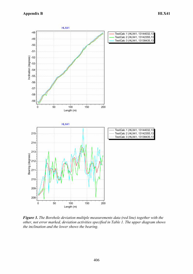
Appendix B HLX41
406
TestCalc 1 (HLX41, 13144032,13TestCalc 2 (HLX41, 13142355,13TestCalc 3 (HLX41, 13138435,13
HLX41
Length (m)200150100500
Incl
inat
ion
(deg
rees
)-48
-49
-50
-51
-52
-53
-54
-55
-56
-57
-58
-59
TestCalc 1 (HLX41, 13144032,13TestCalc 2 (HLX41, 13142355,13TestCalc 3 (HLX41, 13138435,13
HLX41
Length (m)200150100500
Bear
ing
(deg
rees
)
215
214
213
212
211
210
209
208
Figure 3. The Borehole deviation multiple measurements data (red line) together with the other, not error marked, deviation activities specified in Table 1. The upper diagram shows the inclination and the lower shows the bearing.

Appendix B HLX41
407
Table 1. The deviation logging activities in Sicada for HLX41. Idcode Activity
Id Activity Type Code
Activity Start Date Secup (m)
Seclow (m)
Flags _Indat
HLX41 13142355 EG157 Magnetic - accelerometer measurement 2006-09-19 20:30 0.00 198.00 CF 070102 14:18 HLX41 13121670 EG157 Magnetic - accelerometer measurement 2006-09-19 20:30 0.00 198.00 EF 070102 14:01 HLX41 13138435 EG157 Magnetic - accelerometer measurement 2006-09-19 21:04 0.00 198.00 CF 070105 13:40 HLX41 13144032 EG154 Borehole deviation multiple measurements 2007-01-05 13:50 I C 070214 09:03
Table 2. Content of the EG154-file. Idcode Deviation Activity Id Deviation Angle Type Approved Secup
(m) Approved Seclow (m)
Man Estim Angle Uncert (degrees)
HLX41 13138435 BEARING 18.00 198.00 HLX41 13138435 INCLINATION 3.00 198.00 HLX41 13142355 BEARING 18.00 198.00 HLX41 13142355 INCLINATION 3.00 198.00
Table 3. Subset (for every approx. 20 m elevation) of the resulting “Object_location” in Sicada. Idcode Northing
(m) Easting
(m) Elevation
(m) Length
(m) Elevation
Uncertainty Inclination (degrees)
Bearing (degrees)
Inclination Uncertainty
Bearing Uncertainty
Radius Uncertainty
HLX41 6367013.20 1547017.61 21.80 0.00 0.00 -59.15 208.29 0.2 1.5 0.00 HLX41 6367000.91 1547010.68 -1.22 27.00 0.05 -57.64 211.79 0.2 1.5 0.38 HLX41 6366991.12 1547004.75 -18.83 48.00 0.09 -56.20 210.82 0.2 1.5 0.69 HLX41 6366979.38 1546997.84 -38.58 72.00 0.14 -54.84 210.64 0.2 1.5 1.06 HLX41 6366965.86 1546989.60 -60.45 99.00 0.20 -53.25 210.78 0.2 1.5 1.48 HLX41 6366953.45 1546981.90 -79.50 123.00 0.25 -51.88 211.82 0.2 1.5 1.88 HLX41 6366939.13 1546972.73 -100.47 150.00 0.31 -50.07 210.68 0.2 1.5 2.33 HLX41 6366924.17 1546963.64 -121.02 177.00 0.37 -48.95 211.43 0.2 1.5 2.80 HLX41 6366911.44 1546955.86 -137.87 199.50 0.42 -48.15 211.60 0.2 1.5 3.21
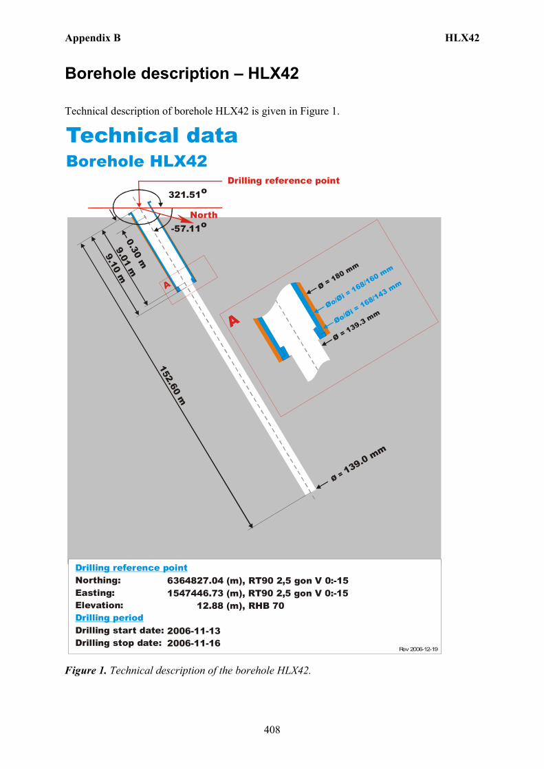
Appendix B HLX42
408
Borehole description – HLX42
Technical description of borehole HLX42 is given in Figure 1.
North
Technical dataBorehole HLX42
6364827.04 (m),(m),
12.88 (m),
2006-11-132006-11-16
1547446.73 RT90 2,5 gon V 0:-15 RHB 70
RT90 2,5 gon V 0:-15
-57.11o
Ø = 139.0 mm
152.60 m
Øo/Øi = 168/160 mm
Ø = 180 mm
Ø = 139.3 mm
A
A
321.51o
Øo/Øi = 168/143 mm
9.10 m9.01 m
Drilling reference point
Northing:Easting:Elevation:
Drilling start date:Drilling stop date:
Drilling reference point
Drilling period
Rev 2006-12-19
0.30 m
Figure 1. Technical description of the borehole HLX42.
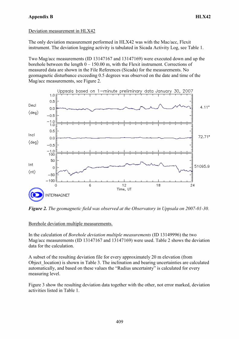
Appendix B HLX42
409
Deviation measurement in HLX42 The only deviation measurement performed in HLX42 was with the Mac/acc, Flexit instrument. The deviation logging activity is tabulated in Sicada Activity Log, see Table 1. Two Mag/acc measurements (ID 13147167 and 13147169) were executed down and up the borehole between the length 0 – 150.00 m, with the Flexit instrument. Corrections of measured data are shown in the File References (Sicada) for the measurements. No geomagnetic disturbance exceeding 0.5 degrees was observed on the date and time of the Mag/acc measurements, see Figure 2.
Figure 2. The geomagnetic field was observed at the Observatory in Uppsala on 2007-01-30.
Borehole deviation multiple measurements. In the calculation of Borehole deviation multiple measurements (ID 13149996) the two Mag/acc measurements (ID 13147167 and 13147169) were used. Table 2 shows the deviation data for the calculation. A subset of the resulting deviation file for every approximately 20 m elevation (from Object_location) is shown in Table 3. The inclination and bearing uncertainties are calculated automatically, and based on these values the “Radius uncertainty” is calculated for every measuring level. Figure 3 show the resulting deviation data together with the other, not error marked, deviation activities listed in Table 1.

Appendix B HLX42
410
TestCalc 1 (HLX42, 13149996,13TestCalc 2 (HLX42, 13147167,13TestCalc 3 (HLX42, 13147169,13
HLX42
Length (m)150100500
Incl
inat
ion
(deg
rees
)
-55
-56
-57
TestCalc 1 (HLX42, 13149996,13TestCalc 2 (HLX42, 13147167,13TestCalc 3 (HLX42, 13147169,13
HLX42
Length (m)150100500
Bear
ing
(deg
rees
)
322
321
Figure 3. The Borehole deviation multiple measurements data (red line) together with the other, not error marked, deviation activities specified in Table 1. The upper diagram shows the inclination and the lower shows the bearing.
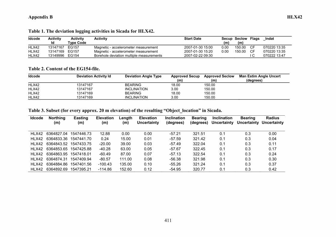
Appendix B HLX42
411
Table 1. The deviation logging activities in Sicada for HLX42. Idcode Activity
Id Activity Type Code
Activity Start Date Secup (m)
Seclow (m)
Flags _Indat
HLX42 13147167 EG157 Magnetic - accelerometer measurement 2007-01-30 15:00 0.00 150.00 CF 070220 13:35 HLX42 13147169 EG157 Magnetic - accelerometer measurement 2007-01-30 15:20 0.00 150.00 CF 070220 13:35 HLX42 13149996 EG154 Borehole deviation multiple measurements 2007-02-22 09:30 I C 070222 13:47
Table 2. Content of the EG154-file. Idcode Deviation Activity Id Deviation Angle Type Approved Secup
(m) Approved Seclow (m)
Man Estim Angle Uncert (degrees)
HLX42 13147167 BEARING 18.00 150.00 HLX42 13147167 INCLINATION 3.00 150.00 HLX42 13147169 BEARING 18.00 150.00 HLX42 13147169 INCLINATION 3.00 150.00
Table 3. Subset (for every approx. 20 m elevation) of the resulting “Object_location” in Sicada. Idcode Northing
(m) Easting
(m) Elevation
(m) Length
(m) Elevation
Uncertainty Inclination (degrees)
Bearing (degrees)
Inclination Uncertainty
Bearing Uncertainty
Radius Uncertainty
HLX42 6364827.04 1547446.73 12.88 0.00 0.00 -57.21 321.51 0.1 0.3 0.00 HLX42 6364833.36 1547441.70 0.24 15.00 0.01 -57.59 321.42 0.1 0.3 0.04 HLX42 6364843.52 1547433.75 -20.00 39.00 0.03 -57.49 322.04 0.1 0.3 0.11 HLX42 6364853.65 1547425.88 -40.28 63.00 0.05 -57.67 322.45 0.1 0.3 0.17 HLX42 6364863.95 1547418.01 -60.49 87.00 0.07 -57.13 322.54 0.1 0.3 0.24 HLX42 6364874.31 1547409.94 -80.57 111.00 0.08 -56.38 321.98 0.1 0.3 0.30 HLX42 6364884.86 1547401.56 -100.43 135.00 0.10 -55.26 321.24 0.1 0.3 0.37 HLX42 6364892.69 1547395.21 -114.86 152.60 0.12 -54.95 320.77 0.1 0.3 0.42
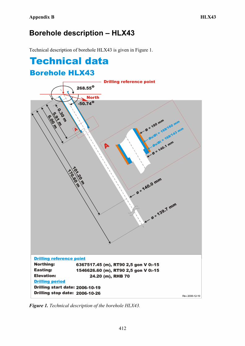
Appendix B HLX43
412
Borehole description – HLX43
Technical description of borehole HLX43 is given in Figure 1.
North
Technical dataBorehole HLX43
6367517.45 (m),(m),
24.20 (m),
2006-10-192006-10-26
1546626.60 RT90 2,5 gon V 0:-15 RHB 70
RT90 2,5 gon V 0:-15
-50.74o
Ø = 139.7 mm
101.20 m
Øo/Øi = 168/160 mm
Ø = 180 mm
Ø = 140.1 mm
A
A
268.55o
Øo/Øi = 168/143 mm
6.00 m5.91 m
Drilling reference point
Northing:Easting:Elevation:
Drilling start date:Drilling stop date:
Drilling reference point
Drilling period
Rev 2006-12-19
0.30 m170.60 m
Ø = 140.0 mm
Figure 1. Technical description of the borehole HLX43.
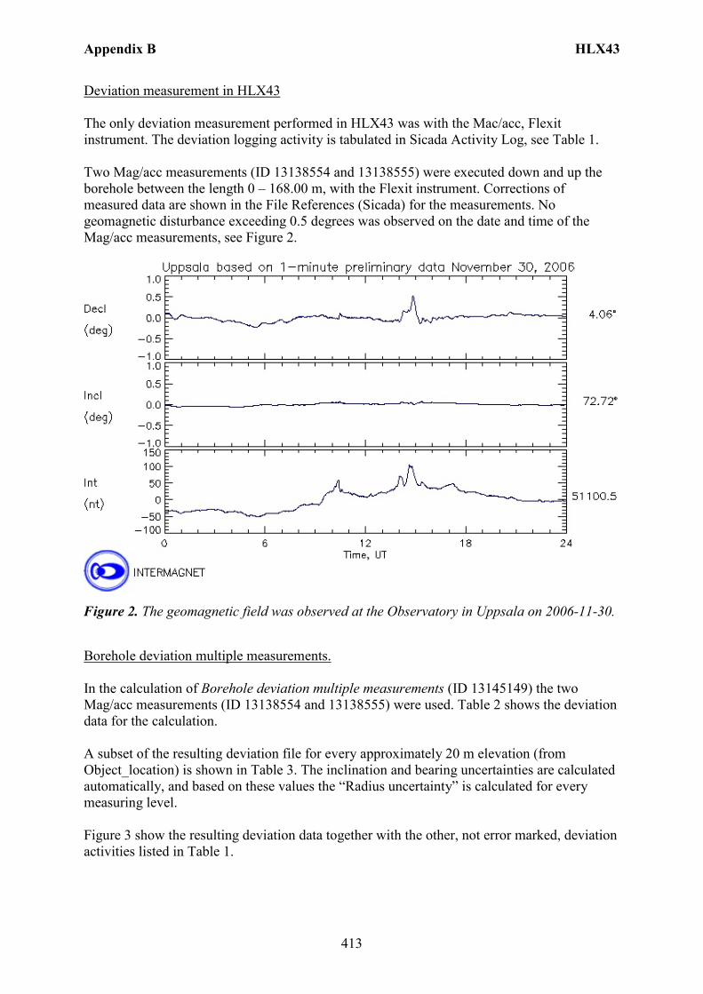
Appendix B HLX43
413
Deviation measurement in HLX43 The only deviation measurement performed in HLX43 was with the Mac/acc, Flexit instrument. The deviation logging activity is tabulated in Sicada Activity Log, see Table 1. Two Mag/acc measurements (ID 13138554 and 13138555) were executed down and up the borehole between the length 0 – 168.00 m, with the Flexit instrument. Corrections of measured data are shown in the File References (Sicada) for the measurements. No geomagnetic disturbance exceeding 0.5 degrees was observed on the date and time of the Mag/acc measurements, see Figure 2.
Figure 2. The geomagnetic field was observed at the Observatory in Uppsala on 2006-11-30.
Borehole deviation multiple measurements. In the calculation of Borehole deviation multiple measurements (ID 13145149) the two Mag/acc measurements (ID 13138554 and 13138555) were used. Table 2 shows the deviation data for the calculation. A subset of the resulting deviation file for every approximately 20 m elevation (from Object_location) is shown in Table 3. The inclination and bearing uncertainties are calculated automatically, and based on these values the “Radius uncertainty” is calculated for every measuring level. Figure 3 show the resulting deviation data together with the other, not error marked, deviation activities listed in Table 1.
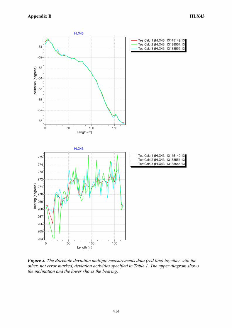
Appendix B HLX43
414
TestCalc 1 (HLX43, 13145149,13TestCalc 2 (HLX43, 13138554,13TestCalc 3 (HLX43, 13138555,13
HLX43
Length (m)150100500
Incl
inat
ion
(deg
rees
)
-51
-52
-53
-54
-55
-56
-57
-58
TestCalc 1 (HLX43, 13145149,13TestCalc 2 (HLX43, 13138554,13TestCalc 3 (HLX43, 13138555,13
HLX43
Length (m)150100500
Bear
ing
(deg
rees
)
275
274
273
272
271
270
269
268
267
266
265
264
Figure 3. The Borehole deviation multiple measurements data (red line) together with the other, not error marked, deviation activities specified in Table 1. The upper diagram shows the inclination and the lower shows the bearing.
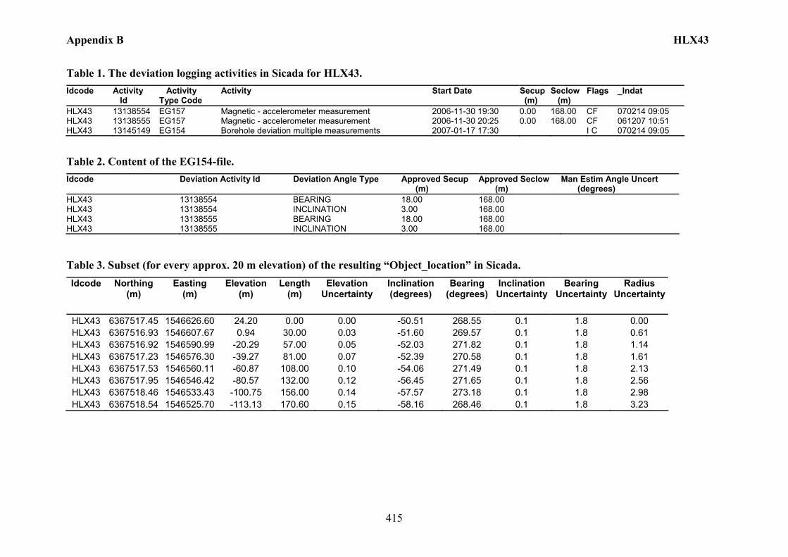
Appendix B HLX43
415
Table 1. The deviation logging activities in Sicada for HLX43. Idcode Activity
Id Activity Type Code
Activity Start Date Secup (m)
Seclow (m)
Flags _Indat
HLX43 13138554 EG157 Magnetic - accelerometer measurement 2006-11-30 19:30 0.00 168.00 CF 070214 09:05 HLX43 13138555 EG157 Magnetic - accelerometer measurement 2006-11-30 20:25 0.00 168.00 CF 061207 10:51 HLX43 13145149 EG154 Borehole deviation multiple measurements 2007-01-17 17:30 I C 070214 09:05
Table 2. Content of the EG154-file. Idcode Deviation Activity Id Deviation Angle Type Approved Secup
(m) Approved Seclow (m)
Man Estim Angle Uncert (degrees)
HLX43 13138554 BEARING 18.00 168.00 HLX43 13138554 INCLINATION 3.00 168.00 HLX43 13138555 BEARING 18.00 168.00 HLX43 13138555 INCLINATION 3.00 168.00
Table 3. Subset (for every approx. 20 m elevation) of the resulting “Object_location” in Sicada. Idcode Northing
(m) Easting
(m) Elevation
(m) Length
(m) Elevation
Uncertainty Inclination (degrees)
Bearing (degrees)
Inclination Uncertainty
Bearing Uncertainty
Radius Uncertainty
HLX43 6367517.45 1546626.60 24.20 0.00 0.00 -50.51 268.55 0.1 1.8 0.00 HLX43 6367516.93 1546607.67 0.94 30.00 0.03 -51.60 269.57 0.1 1.8 0.61 HLX43 6367516.92 1546590.99 -20.29 57.00 0.05 -52.03 271.82 0.1 1.8 1.14 HLX43 6367517.23 1546576.30 -39.27 81.00 0.07 -52.39 270.58 0.1 1.8 1.61 HLX43 6367517.53 1546560.11 -60.87 108.00 0.10 -54.06 271.49 0.1 1.8 2.13 HLX43 6367517.95 1546546.42 -80.57 132.00 0.12 -56.45 271.65 0.1 1.8 2.56 HLX43 6367518.46 1546533.43 -100.75 156.00 0.14 -57.57 273.18 0.1 1.8 2.98 HLX43 6367518.54 1546525.70 -113.13 170.60 0.15 -58.16 268.46 0.1 1.8 3.23