Embed Size (px)
Citation preview

CanSat 2019 CDR: Team 4440 White Noise 1
CanSat 2019 Critical Design Review (CDR)
OutlineVersion 1.1
4440White Noise
2
Presentation Outline
CanSat 2019 CDR: Team 4440 White Noise
Presenters:
Dimitris Bralios Miltiadis Stouras Marios Papachristou George Rapakoulias Ioannis Christodoulou
Systems Overview: George Rapakoulias slides 6-23Sensor Subsystem Design: Dimitrios Bralios slides 24-37Descent Control Design: Marios Papachristou & George Rapakoulias slides 38-53Mechanical Subsystem Design: Ioannis Christodoulou & George Rapakoulias slides 54-75CDH Subsystem Design: Dimitrios Bralios & Spyros Pavlatos slides 76-88Electrical Power Subsystem Design: Dimitrios Bralios slides 89-101Flight Software Design: Miltiadis Stouras slides 102-110Ground Control System Design: Spyros Pavlatos & Miltiadis Stouras slides 111-120CanSat Integration and Test: Dimitrios Bralios slides 121-134Mission Operations and Analysis: Miltiadis Stouras slides 135-141Requirements Compliance: Dimitrios Bralios slides 142-150Management: Dimitrios Bralios slides 151-167
Spyros Pavlatos
Presenter: George Rapakoulias

3
Team Organization
CanSat 2019 CDR: Team 4440 White Noise
NAME YEAR Subject of study
Dimitrios Bralios 3 Electrical & Computer Engineering
Chariton Charitonidis 3 Electrical & Computer Engineering
Ioannis Christodoulou 3 Mechanical Engineering
Iasonas Nikolaou 3 Electrical & Computer Engineering
Marios Papachristou 4 Electrical & Computer Engineering
Spyros Pavlatos 3 Electrical & Computer Engineering
George Rapakoulias 3 Mechanical Engineering
Miltiadis Stouras 3 Electrical & Computer Engineering
Neoklis Vaindirlis 3 Electrical & Computer Engineering
Faculty Advisor Evangelos Papadopoulos Department of Mechanical Engineering, NTUA

4
Team Organization
CanSat 2019 CDR: Team 4440 White Noise
Organizational chart

5
Acronyms
Presenter: George Rapakoulias CanSat 2019 CDR: Team 4440 White Noise
ABS: Acrylonitrile Butadiene StyreneAC: Alternating CurrentASCII: American Standard Code for Information InterchangeAT: Application TransparentBEM: Blade Element MomentumBIBO: Bounded Input Bounded OutputCAD: Computer Aided DesignCDH: Communication Data HandleCDR: Critical Design ReviewCG: Center of GravityCONOPS: Concepts of OperationsCP: Center of PressureCSV: Comma Separated ValuesDOF: Degrees Of FreedomEEPROM: Electrically Erasable Programmable Read-Only MemoryEPS: Electrical Power SubsystemFPS: Frames Per SecondFSW: Flight SoftwareGCS: Ground Control SystemGPS: Global Positioning SystemI2C: Inter-Integrated Circuit
IDE: Integrated Development EnvironmentIEEE: Institute of Electrical and Electronics EngineersIMU: Inertial Measurement SystemLED: Light Emitting DiodeLQR: Linear Quadratic RegulatorLSB: Least Significant BitLTS: Long-Term SupportMOSFET: Metal-Oxide-Semiconductor Field-Effect TransistorNACA:National Advisory Committee for AeronauticsNETID: Network IDNTUA: National Technical University of AthensPCB: Printed Circuit BoardPDR : Preliminary Design ReviewPFR: Post Flight ReviewPLA: PolyLactic AcidPPM: Parts Per MillionRAM: Random Access MemoryRC: Radio ControlledRPM: Rotations Per Minute
RTC: Real Time ClockS.Steel: Stainless SteelSCCB: Serial Camera Control BusSD: Security DigitalSMA: Sub Micro type A connector SPI: Serial Peripheral InterfaceTC: Transition CounterUSB: Universal Serial BusVSWR: Voltage Standing Wave Ratio
VM:Verification MethodA: AnalysisI: InspectionT: TestingD: Demonstration

6
System Overview
George Rapakoulias
CanSat 2019 CDR: Team 4440 White Noise

7
Mission Summary
CanSat 2019 CDR: Team 4440 White Noise
• This year’s mission is to build an autogyro based descent control systemSpecifically the mission will be as follows: – CanSat will be launched via a rocket at ~700 m– When apogee is reached, it will exit the rocket and parachute will deploy– It will descent to 450 m. At this altitude the payload will separate from the
container and deploy its descent mechanisms. Container will continue its descent
– Paload will use a passive autogyro rotor for slowing down its descent rate to ~11 m/s
– After payload lands, an audio beacon will facilitate recovery• Out team has selected the bonus objective because
– Implementing just the autogyro mechanism will leave plenty of free space– Ιntegration of a camera stabilization mechanism does not pose any
significant problems to the design
Presenter: George Rapakoulias

Summary of Changes Since PDR
After completing the prototyping stage of the project, our team has made the following improvements in our design:
• The descent control strategy has changed from a completely active to a combination of active and passive design.
• We have changed the material of some parts, like the blades, in order to simplify the construction process
• We have changed the position and shape of the electronics board• We have made minor changes in dimensions reinforcing our design where
needed
8CanSat 2019 CDR: Team 4440 White NoisePresenter: George Rapakoulias

System Requirement Summary
CanSat 2019 CDR: Team #4440 White Noise 9
No Requirement PriorityVM
A I T D
1 Total mass of the CanSat (science payload and container) shall be 500 grams +/- 10 grams
HIGH X X X
2 CanSat shall fit in a cylindrical envelope of 125 mm diameter x 310 mm length HIGH X X
3 The container shall not have any sharp edges to cause it to get stuck in the rocket payload section which is made of cardboard
MEDIUM X
4 The container shall be a fluorescent color; pink, red or orange LOW X
5 The rocket airframe shall not be used to restrain any deployable parts of the CanSat.
MEDIUM X
6 The rocket airframe shall not be used as part of the CanSat operations. MEDIUM X
7 The CanSat shall deploy from the rocket payload section and immediately deploy the container parachute.
MEDIUM X
8 The descent rate of the CanSat (container and science payload) shall be 20 meters/second +/- 5m/s
HIGH/ MEDIUM
X X
9 The container shall release the payload at 450 meters +/- 10 meters. MEDIUM X X
Presenter: George Rapakoulias

System Requirement Summary
CanSat 2019 CDR: Team #4440 White Noise 10
No Requirement PriorityVM
A I T D
10 The science payload shall descend using an auto-gyro descent control system. HIGH X X
11 The descent rate of the science payload after being released from the container shall be 10 to 15 meters/second
HIGH X X
12 All descent control device attachment components shall survive 30 Gs of shock.
HIGH X X X
13 All electronic components shall be enclosed and shielded from the environment with the exception of sensors.
MEDIUM X X
14 All structures shall be built to survive 15 Gs of launch acceleration. HIGH X X
15 All structures shall be built to survive 30 Gs of shock. HIGH X X
16 All electronics shall be hard mounted using proper mounts such as standoffs, screws, or high performance adhesives.
MEDIUΜ X X
17 All mechanisms shall be capable of maintaining their configuration or states under all forces.
MEDIUM X X
18 Mechanisms shall not use pyrotechnics or chemicals. MEDIUM X
Presenter: George Rapakoulias

System Requirement Summary
CanSat 2019 CDR: Team #4440 White Noise 11
No Requirement PriorityVM
A I T D
19 Mechanisms that use heat (e.g., nichrome wire) shall not be exposed to the outside environment to reduce potential risk of setting vegetation on fire.
HIGH X X
20 The science payload shall measure altitude using an air pressure sensor. HIGH X X
21 The science payload shall provide position using GPS. HIGH X X
22 The science payload shall measure its battery voltage. HIGH X X
23 The science payload shall measure outside temperature. HIGH X X
24 The science payload shall measure the spin rate of the auto-gyro blades relative to the science vehicle.
HIGH X X
25 The science payload shall measure pitch and roll HIGH X X
26 The probe shall transmit all sensor data in the telemetry HIGH X X
27 The Parachute shall be fluorescent Pink or Orange LOW X
Presenter: George Rapakoulias

System Requirement Summary
CanSat 2019 CDR: Team #4440 White Noise 12
No Requirement PriorityVM
A I T D
28 The ground station shall be able to command the science vehicle to calibrate barometric altitude, and roll and pitch angles to zero as the payload sits on the launch pad.
HIGH X X
29 The ground station shall generate a csv file of all sensor data as specified in the telemetry section
MEDIUM X
30 Telemetry shall include mission time with one second or better resolution. Mission time shall be maintained in the event of a processor reset during the launch and mission.
MEDIUM X X
31 XBEE radios shall be used for telemetry. 2.4 GHz Series radios are allowed. 900 MHz XBEE Pro radios are also allowed.
HIGH X
32 XBEE radios shall have their NETID/PANID set to their team number. MEDIUM X X
33 XBEE radios shall not use broadcast mode. HIGH X X
34 Cost of the CanSat shall be under $1000. Ground support and analysis tools are not included in the cost
HIGH X
35 Each team shall develop their own ground station. HIGH X
Presenter: George Rapakoulias
System Requirement Summary
CanSat 2019 CDR: Team #4440 White Noise 13
No Requirement PriorityVM
A I T D
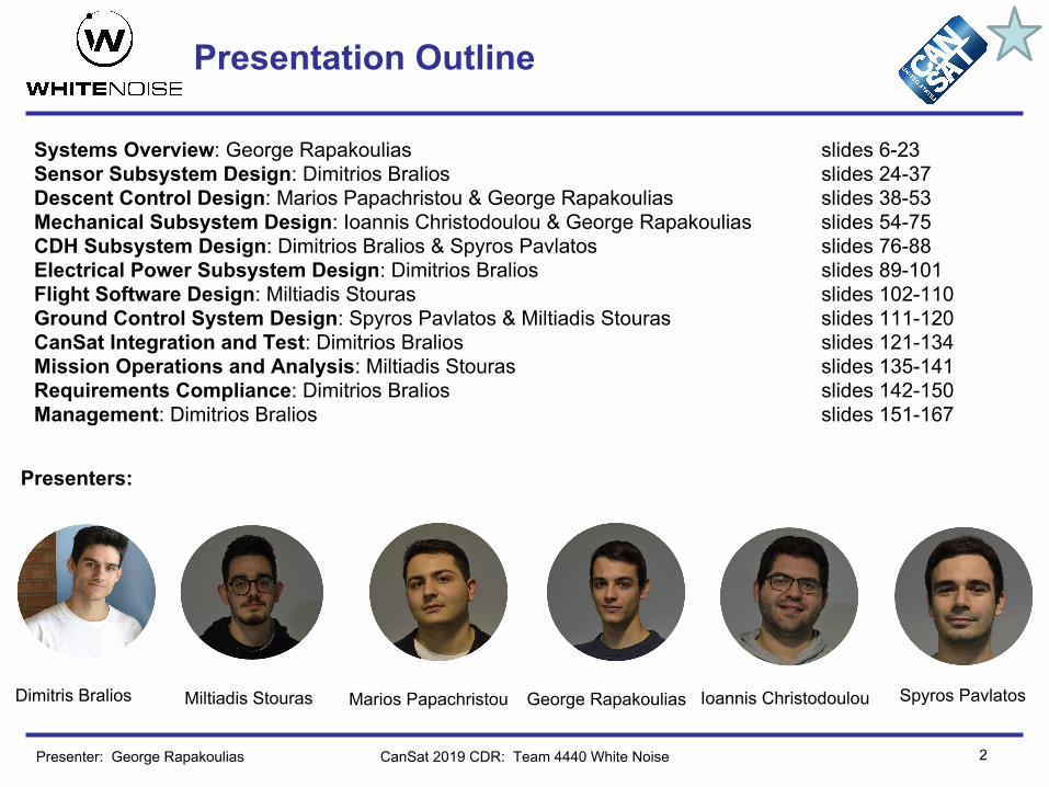
36 All telemetry shall be displayed in real time during descent. MEDIUM X X X
37 All telemetry shall be displayed in engineering units (meters, meters/sec, Celsius, etc.)
MEDIUM X
38 Teams shall plot each telemetry data field in real time during flight. MEDIUM X
39 The ground station shall include one laptop computer with a minimum of two hours of battery operation, XBEE radio and a hand-held antenna.
HIGH X X
40 The ground station must be portable so the team can be positioned at the ground station operation site along the flight line. AC power will not be available at the ground station operation site.
LOW X X
41 Both the container and probe shall be labeled with team contact information including email address.
MEDIUM X
42 The flight software shall maintain a count of packets transmitted, which shall increment with each packet transmission throughout the mission. The value shall be maintained through processor resets.
HIGH X X
44 No lasers allowed. LOW X
Presenter: George Rapakoulias

System Requirement Summary
CanSat 2019 CDR: Team #4440 White Noise 14
No Requirement PriorityVM
A I T D
45 The probe must include an easily accessible power switch that can be accessed without disassembling the cansat and in the stowed configuration.
MEDIUM X X
46 The probe must include a power indicator such as an LED or sound generating device that can be easily seen without disassembling the cansat and in the stowed state.
MEDIUM X X
47 An audio beacon is required for the probe. It may be powered after landing or operate continuously
HIGH X
48 The audio beacon must have a minimum sound pressure level of 92 dB, unobstructed.
MEDIUM X X
49 Battery source may be alkaline, Ni-Cad, Ni-MH or Lithium. Lithium polymer batteries are not allowed. Lithium cells must be manufactured with a metal package similar to 18650 cells.
MEDIUM X X
50 An easily accessible battery compartment must be included allowing batteries to be installed or removed in less than a minute and not require a total disassembly of the CanSat.
MEDIUM X
51 Spring contacts shall not be used for making electrical connections to batteries. Shock forces can cause momentary disconnects.
HIGH X
Presenter: George Rapakoulias

System Requirement Summary
CanSat 2019 CDR: Team #4440 White Noise 15
No Requirement PriorityVM
A I T D
52 The auto-gyro descent control shall not be motorized. It must passively rotate during descent.
HIGH X X
53 The GPS receiver must use the NMEA 0183 GGA message format. MEDIUM X X
54 The CANSAT must operate during the environmental tests. HIGH X X
55 Payload/Container shall operate for a minimum of two hours when integrated into rocket.
HIGH X X X
Presenter: George Rapakoulias

System Requirement Summary
CanSat 2019 CDR: Team #4440 White Noise 16
No Requirement PriorityVM
A I T D
Bonus 1
A video camera shall be integrated into the science payload to record the descent after being released from the container.
MEDIUM X
Bonus 2
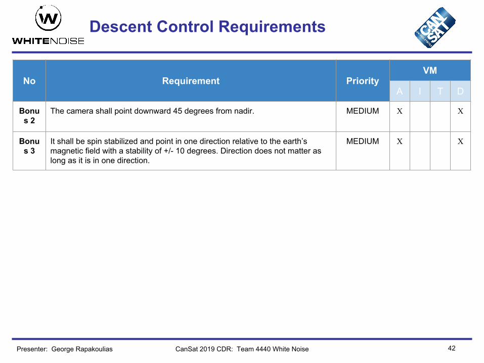
The camera shall point downward 45 degrees from nadir. MEDIUM X X
Bonus 3
It shall be spin stabilized and point in one direction relative to the earth’s magnetic field with a stability of +/- 10 degrees. Direction does not matter as long as it is in one direction.
MEDIUM X X
Bonus 4
Video shall be in color with a minimum resolution of 640x480 pixels and 30 frames per second
LOW/ MEDIUM
X X
Bonus 5
The direction the camera is pointed relative to earth’s magnetic north shall be included in the telemetry.
MEDIUM X
Presenter: George Rapakoulias

17
Payload Physical Layout
CanSat 2019 CDR: Team 4440 White Noise
Container Subassembly
Level 3: Autogyro attachment point
Level 2: Foldable control fins
Electronics
Level 1: Foldable landing gear
Camera gimbal
Container retaining pads
Foldable Rotor Subassembly
Presenter: George Rapakoulias

18
Payload Physical Layout
CanSat 2019 CDR: Team 4440 White Noise
All dimensions in millimeters
Presenter: George Rapakoulias

19
System Concept of Operations
CanSat 2019 CDR: Team 4440 White NoisePresenter: George Rapakoulias
20
System Concept of Operations
CanSat 2019 CDR: Team 4440 White Noise
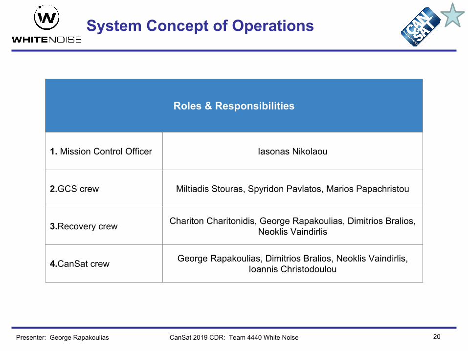
Roles & Responsibilities
1. Mission Control Officer Iasonas Nikolaou
2.GCS crew Miltiadis Stouras, Spyridon Pavlatos, Marios Papachristou
3.Recovery crew Chariton Charitonidis, George Rapakoulias, Dimitrios Bralios, Neoklis Vaindirlis
4.CanSat crew George Rapakoulias, Dimitrios Bralios, Neoklis Vaindirlis, Ιοannis Christodoulou
Presenter: George Rapakoulias

21
System Concept of Operations
CanSat 2019 CDR: Team 4440 White Noise
Pre-Flight
Flight
Post-Flight
1 2
3
4 44 22
3 421 3 4212
Note: 1,2,3,4 indicate the teams mentioned in the previous slide
Presenter: George Rapakoulias

22
Launch Vehicle Compatibility
• Include a dimensioned drawing that shows clearances with the payload section– Focus on launch configuration (Container + Payload)– Include all descent control apparatus (no sharp protrusions)– What is the clearance? (Leave margin to allow easy deployment!)
• Notes:– In past years there were a large number of CanSats that did not
deploy from the payload sections of the rocket because of protrusions or because the CanSat was too wide to fit in the rocket
– Lack of sharp protrusions and fit within the Launch Vehicle will also be scored at the Flight Readiness Review
CanSat 2019 CDR: Team 4440 White NoisePresenter: George Rapakoulias

23
Launch Vehicle Compatibility
CanSat 2019 CDR: Team 4440 White Noise
Rocket compartment
Container with payload
● In order to guarantee that the cansat will exit the rocket flawlessly, we have left a 0,5 mm radial and 1 mm axial margin from the rocket compartment.
● As indicated on the left drawing, there are no sharp protrusions from the container. As seen from top, it is fully circular
All dimensions are in millimeters.
Presenter: George Rapakoulias

24
Sensor Subsystem Design
Dimitrios Bralios
CanSat 2019 CDR: Team 4440 White Noise

25
Sensor Subsystem Overview
Presenter: Dimitrios Bralios CanSat 2019 CDR: Team 4440 White Noise
Sensors Component Type Component Model
Air Pressure Air Pressure sensor BMP280
Air Temperature Temperature sensor BMP280
GPS GPS Adafruit Ultimate GPS
Voltage Voltage Divider Resistors
Pitch and Roll IMU 9 DOF Adafruit BNO055
Blade Spin Rate Hall Effect Sensor andMicrocontroller
US5881 and ATtiny85
Camera Camera Adafruit #3202

Sensor Changes Since PDR
26CanSat 2019 CDR: Team 4440 White Noise
Sensors PDR CDR Rationale
Air Pressure BMP388 BMP280 Wider availabilityLower power consumptionBoth have comparable accuracyAir Temperature BMP388 BMP280
Presenter: Dimitrios Bralios
Details of changes are discussed in subsequent slides.

27
Sensor Subsystem Requirements
CanSat 2019 CDR: Team 4440 White NoisePresenter: Dimitrios Bralios
No Requirement PriorityVM
A I T D
1Total mass of the CanSat (science payload and container) shall be 500 grams +/- 10 grams. HIGH X X
13All electronic components shall be enclosed and shielded from the environment with the exception of sensors. MEDIUM X X
20 The science payload shall measure altitude using an air pressure sensor. HIGH X X
21 The science payload shall provide position using GPS. HIGH X X
22 The science payload shall measure its battery voltage. HIGH X X
23 The science payload shall measure outside temperature. HIGH X X
24The science payload shall measure the spin rate of the auto-gyro blades relative to the science vehicle. HIGH X X
25 The science payload shall measure pitch and roll. HIGH X X

28
Sensor Subsystem Requirements
CanSat 2019 CDR: Team 4440 White NoisePresenter: Dimitrios Bralios
No Requirement PriorityVM
A I T D
34Cost of the CanSat shall be under $1000. Ground support and analysis tools are not included in the cost. HIGH X
53 The GPS receiver must use the NMEA 0183 GGA message format. MEDIUM X X
55Payload/Container shall operate for a minimum of two hours when integrated into rocket. HIGH X X X
Bonus 1
A video camera shall be integrated into the science payload to record the descent after being released from the container. MEDIUM X
Bonus 4
Video shall be in color with a minimum resolution of 640x480 pixels and 30 frames per second. MEDIUM X X
29
Payload Air Pressure Sensor Summary
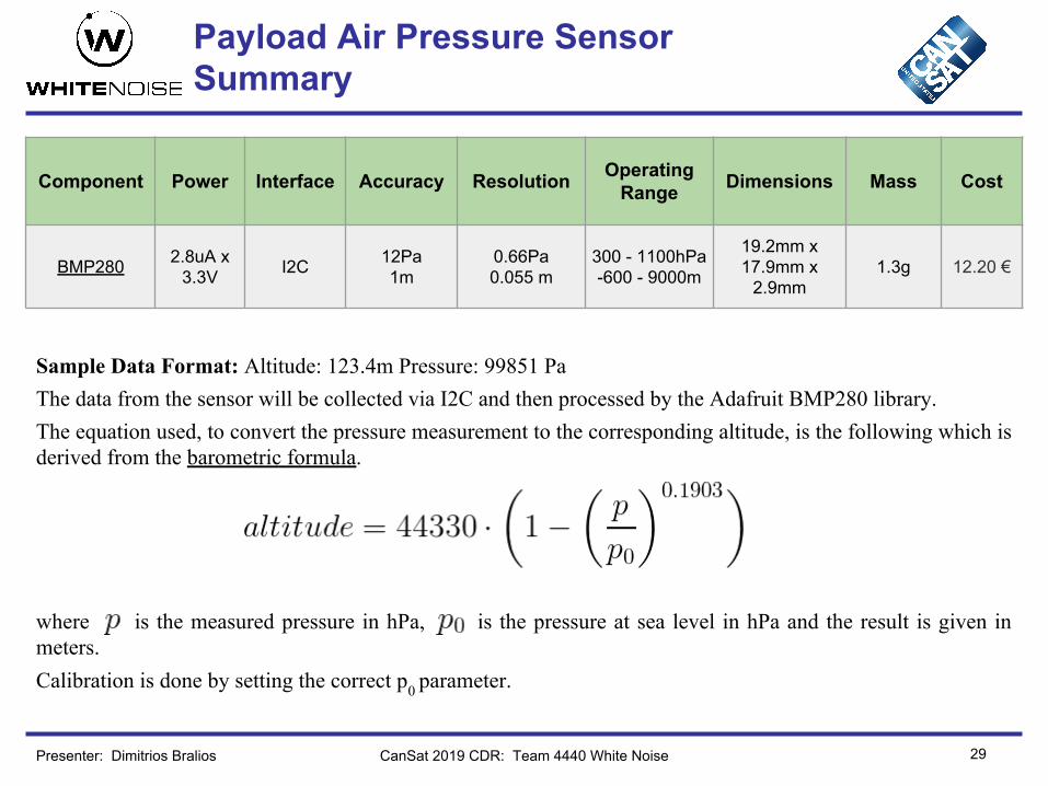
Sample Data Format: Altitude: 123.4m Pressure: 99851 Pa The data from the sensor will be collected via I2C and then processed by the Adafruit BMP280 library. The equation used, to convert the pressure measurement to the corresponding altitude, is the following which is derived from the barometric formula.
where is the measured pressure in hPa, is the pressure at sea level in hPa and the result is given in meters.Calibration is done by setting the correct p0 parameter.
CanSat 2019 CDR: Team 4440 White NoisePresenter: Dimitrios Bralios
Component Power Interface Accuracy Resolution Operating Range Dimensions Mass Cost
BMP280 2.8uA x 3.3V I2C 12Pa
1m0.66Pa0.055 m
300 - 1100hPa-600 - 9000m
19.2mm x 17.9mm x
2.9mm1.3g 12.20 €

30
Payload Air Temperature Sensor Summary
Sample Data Format: 12.34 °CThe data from the sensor will be collected via I2C and then processed by the Adafruit BMP280 library.Calibration can be performed using the API provided by Bosch Sensortec.
CanSat 2019 CDR: Team 4440 White NoisePresenter: Dimitrios Bralios
Component Power Interface Accuracy Resolution Operating Range Dimensions Mass Cost
BMP280 2.8uA x 3.3V I2C 1.0°C 0.01°C
-40 - 85 °C0 - 65 °C
(full accuracy)
19.2mm x 17.9mm x
2.9mm1.3g 12.20 €
BMP388 was replaced by BMP280Rationale
• Wider availability of the BMP280, as it is an more established model.• Both have comparable accuracy in their measurements, well within
competition’s requirements.• Slightly lower power consumption

31
GPS Sensor Summary
CanSat 2019 CDR: Team 4440 White NoisePresenter: Dimitrios Bralios
Component Power Interface Accuracy Resolution Operating Range Dimensions Mass Cost
MTK3339(Adafuit
Ultimate GPS)
20mA x 3.3V Serial <3m, 0.1m/s 0.0001°
0.1m up to 32 km25.5mm x 35mm x 6.5mm
8.5g 34.41 €
Sample Data Format: UTC Time: 06:49:51.000 Latitude: 2307.1256 N Longitude: 12016.4438 E Altitude: 39.9 meters Satellites: 4The data from the sensor will be collected via serial interface and then processed by the Adafruit GPS library. The library extracts the latitude, longitude, altitude, UTC time and the number of satellites from the NMEA packets.
The message format used is the NMEA 0183 GGA. The warm/cold start time is 34 seconds and the update rate goes up to 10Hz.
The altitude measurement can be used as a backup to the measurement of the BMP280.

32
Payload Voltage Sensor Summary
CanSat 2019 CDR: Team 4440 White NoisePresenter: Dimitrios Bralios
Component Power Interface Accuracy Resolution OperatingRange Dimensions Mass Cost
Voltage Divider
(SMD 1% resistors)
0.1mA x 3.6V
1 Analog Pin 1.7% 12 bits
(1.2 mV/LSB) 0 - 5 V2.0 mm × 1.25 mm
(x2)~10mg 1 €
Sample Data Format: 1.234 VTwo SMD resistors with accuracy of 1% will be used. The first having a value of 33kΩ and the second 17kΩ. The teensy ADC reads a 12 bit value, which can be translated to the corresponding voltage value (in Volts) using the following formula.
Based on this formula, the relative accuracy of the voltage value is 1.7%.

33
Pitch/Roll Sensor Summary
CanSat 2019 CDR: Team 4440 White NoisePresenter: Dimitrios Bralios
Component Power Interface Accuracy Resolution Operating Range Dimensions Mass Cost
Adafruit BNO055
12.3mA x 3.3V I2C 0.1°
0.0625°(1 deg / 16
LSB)
up to ±16g
±1300µT ±2000°/s
27.0mm x 20.5mm x
4.0mm 3g 30.70 €
Sample Data Format: Pitch: 12.3° Roll: 12.3° The sensor internally calculates the pitch and roll angles from the accelerometer, gyroscope and magnetometer data. Then the data is collected, via I2C interface, by the Adafruit BNO055 library, which also allows easy calibration. Data collection rate can be configured up to 100Hz.

34
Auto-Gyro Blade Spin Rate Sensor Summary
CanSat 2019 CDR: Team 4440 White NoisePresenter: Dimitrios Bralios
Hall Effect Sensor Type Power Interface Mass Cost
US5881 Non-Latching 2mA x 3.6V 1 Digital Pin 0.12g 3.00 €
Microcontroller Clock Speed Power Interface Mass Cost
ATtiny85 1MHz 5mA x 3.3V I2C 0.5g 1.02 €
Accuracy Resolution Operating Range
4 RPM at 2000 RPM 1 RPM 1 - 5000 RPM
Sample Data Format: 1234 RPM A magnet is attached to the rotor and two hall effect elements are spaced 120 degrees apart, mounted on the CanSat body. The calculation method of the spin rate is the pulse timing method. Each time a magnet passes in front of a hall effect sensor a pulse is produced and an interrupt is triggered on the ATtiny85. The microcontroller counts the period of the rotation, (in number of ticks). The tick length selected is 64μs.Finally, the spin rate measurement is transmitted to the teensy microprocessor via I2C.

35
Auto-Gyro Blade Spin Rate Sensor Summary
CanSat 2019 CDR: Team 4440 White NoisePresenter: Dimitrios Bralios
The equation used to derive the spin rate in RPM from the ticks counted is the following.
Where n is the spin rate in RPM of the rotor and T is the period of the rotation in seconds.The accuracy of the measurement is depends on the current spin rate, as seen in the following graph. At the desired spin rate the accuracy is around 4 RPM.
36
Bonus Objective Camera Summary
CanSat 2019 CDR: Team 4440 White NoisePresenter: Dimitrios Bralios
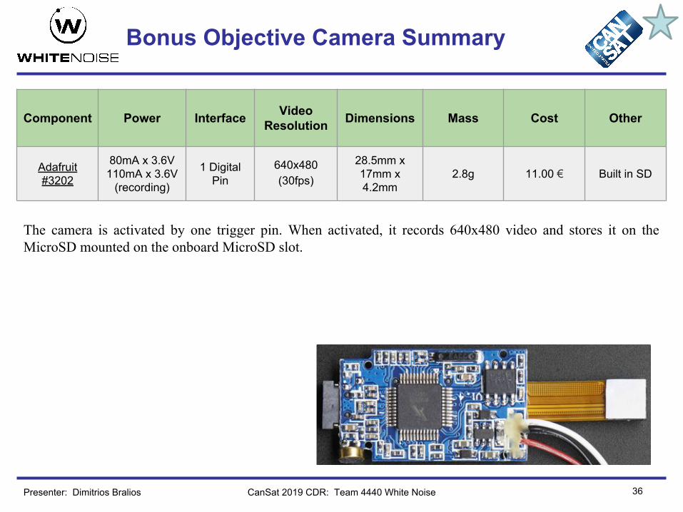
Component Power Interface Video Resolution Dimensions Mass Cost Other
Adafruit #3202
80mA x 3.6V110mA x 3.6V
(recording)
1 Digital Pin
640x480(30fps)
28.5mm x 17mm x 4.2mm
2.8g 11.00 € Built in SD
The camera is activated by one trigger pin. When activated, it records 640x480 video and stores it on the MicroSD mounted on the onboard MicroSD slot.
37
Container Air Pressure Sensor Summary
The container will not have any electronics.
CanSat 2019 CDR: Team 4440 White NoisePresenter: Dimitrios Bralios

38
Descent Control Design
George RapakouliasMarios Papachristou
Miltiadis Stouras
CanSat 2019 CDR: Team 4440 White Noise

39
Descent Control Overview
Presenter: George Rapakoulias
● 1st stage 650-450 m: When apogee is reached the container with the science payload exits the missle. A circular parachute opens immediately and the target terminal velocity is reached within about 2 seconds. Payload is in stowed configuration inside the container during this stage. Container has specially designed pads for retaining the payload in place safely.
● 2nd stage 450m-landing: Container opens and payload is released. The container continues its descent with a lower speed. Science payload deploys blades and fins. Air flow spins the rotor and lift is produced. Stability against tumbling is achieved with a combination of active and passive systems.
CanSat 2019 CDR: Team #4440 White Noise

40
Descent Control Changes Since PDR
Changes since PDR● Blade shape was changed to simplify manufacturing process and save weight● Minor changes to stability control strategy. We will rely on a combination of active/passive control in order to
maintain stability during descent. The rotor will be designed in such a way that pitch and roll will be inherently stable. Therefore the active control surfaces will fine tune pitch and roll, and mainly maintain yaw.
● The changes result in an overall simpler and more robust design while still guaranteeing compliance with mission requirements.
CanSat 2019 CDR: Team 4440 White Noise
Prototyping● Because the final payloads design is too
complex to build during the prototyping phase, we designed a simplified version of it, with the aim to test the descent control mechanisms separately.
● This test platform featured all the components from the final design, without any stowing mechanism(folding joints etc) and a data logging device for recording all critical parameters for the mission, like RPM, heading altitude, etc.
Presenter: George Rapakoulias

41
Descent Control Requirements
CanSat 2019 CDR: Team 4440 White Noise
No Requirement PriorityVM
A I T D
1The descent rate of the CanSat (container and science payload) shall be 20 meters/second +/- 5m/s.
MEDIUM -HIGH X X
2 The science payload shall descend using an autogyro descent control system. HIGH X
3The descent rate of the science payload after being released from the container shall be 10 to 15 meters/second. HIGH X X
4All descent control device attachment components shall survive 30 Gs of shock. HIGH X X X
5 The Parachute shall be fluorescent Pink or Orange MEDIUM X
6The auto-gyro descent control shall not be motorized. It must passively rotate during descent. HIGH X
Presenter: George Rapakoulias
42
Descent Control Requirements
CanSat 2019 CDR: Team 4440 White Noise
No Requirement PriorityVM
A I T D
Bonus 2
The camera shall point downward 45 degrees from nadir. MEDIUM X X
Bonus 3
It shall be spin stabilized and point in one direction relative to the earth’s magnetic field with a stability of +/- 10 degrees. Direction does not matter as long as it is in one direction.
MEDIUM X X
Presenter: George Rapakoulias

43
Payload Descent Control Hardware Summary
CanSat 2019 CDR: Team 4440 White Noise
Payload in stowed configuration
Container splits with hinges, releasing the payload
Release will be triggered with the burn of a retaining rope tied around the carbon rods
Payload in deployed configuration
Active control surfaces for orientation adjustments
Autogyro Rotor
Presenter: George Rapakoulias

44
Payload Descent Control Hardware Summary
CanSat 2019 CDR: Team 4440 White Noise
Key parameters of our design● Blade shape and color:
○ We optimized this parameter and designed a blade that has minimum angular momentum in the equilibrium point, minimizing gyroscopic effects. The process we used is discussed on the next slide.
○ Torsion spring are featured for deploying the blades when they are not spinning. ○ They will be painted in a fluorescent color for easy spotting.
● Placement of CG: This is a very critical parameter for the stability of our system, so we tried to keep it as far apart from the aerodynamic CP as possible, maximizing the stabilizing effect of the lift - weight force couple.
● Active control: ○ For controlling yaw and fine tuning pitch and roll, a closed loop control system is implemented.
Measurements are taken from the IMU sensor and fed to the controller. After the signal is processed, commands are sent to the servos for making adjustments.
○ Control fins equipped with springs for transitioning from stowed to deployed state● Sensor/Actuator accuracy:
Sensor/Actuator Absolute(?) precision
IMU 0.1 deg
Rotor RPM 4 RPM
Sevo 1 deg
Presenter: George Rapakoulias

45
Payload Descent Control Hardware Summary
CanSat 2019 CDR: Team 4440 White Noise
Optimizing Blades’ shape: As we discussed earlier, we developed an optimization algorithm to find a blade shape that minimizes the angular momentum in equilibria and also satisfies the terminal velocity and manufacturing constraints. To begin with, we modeled the chord-radius and twist-radius functions as Bezier curves with 4 and 3 control points respectively, therefore being able to uniquely describe a blade using only 7 variables.
The aerodynamic simulation accepts as input a blade described by the state vector and outputs the angular velocity at the equilibrium and the terminal descent rate. We determined a cost function that we want to minimize :
Where f is a function of the terminal velocity that has 0 cost in the region [10,14] and very large cost values outside that region. The manufacturing constraints imposed to the problem were some limitations on the chord and twist values along the blade. To minimize the cost we used the Projected Gradient Descent algorithm, which improves the blade cost iteratively:
Presenter: Miltiadis Stouras

Descent Stability Control Design
46CanSat 2019 CDR: Team 4440 White Noise 46
The simplified dynamic model using the Euler-Lagrange equations is:
Our goal will be the fine tuning of pitch and roll during descent via active control so that the payload remains nadir oriented. We also need to the control yaw so that the payload does not spin.
Presenter: Marios Papachristou
Pitch and Roll Control: The system is controllable so a state feedback law of the form
In order to send the pitch and roll to zero. The value of the gain matrix K can be chosen arbitrarily such that the closed loop system is stable. The gain choice can be determined via solving an the Linear Quadratic Regulator Optimal Control Problem
Yaw Control: For the yaw axis since no moments can be transferred through the joint in this direction, a moment acting upon the body will not affect the rotor. Therefore the dynamical system equation for the yaw axis is
For the yaw control we can use a PD-PV controller of the form
So the closed-loop system becomes: , which is stable for any positive values of the gains.

Descent Stability Control Design
47CanSat 2019 CDR: Team 4440 White Noise
Active control mechanisms:For exerting the required moments, 3 independently moving fins are used, as described in the PDR. In order to add them in the control loop, we first modeled their interaction with the flow in a matlab code, 2D lift, drag and moment coefficients. Then, values were sampled across the functional range of motion of each fin. The resulting moments have a non-linear relation wrt to the input angles, hence the inversion seemed very challenging since classical numerical methods failed to find solutions. We needed a solution that generalized easily whenever an arbitrary moment vector was provided by the controllers. The idea was initially to keep some representatives of the various data points that we had acquired through sampling via using K-Means clustering and then keeping the angles that their respective moment vectors were the closest to the cluster centers. Then we used these representative data points for the inversion procedure for fitting a hyperplane using these as test data. This model generalizes very well giving a very small error without overfitting.
Plant & Controllers Inverse finsModel Servo Control
Measurements (orientation, angular
velocities)
Presenter: Marios Papachristou

Descent Stability Control Design
48CanSat 2019 CDR: Team 4440 White Noise
Drop test results without control In order to verify that our model is not over idealized, we performed a drop test with our simplified test platform via a drone. The results agreed with our predictions, since the payload has a small orientation oscillation but is otherwise stable. The fins will fins tune this fluctuation and will primarily correct yaw, which in this experiment had a constant speed of about 30 RPM.
LandingRelease
Presenter: George Rapakoulias

49
Container Descent Control Hardware Summary
CanSat 2019 CDR: Team 4440 White Noise
Container in stowed configuration
Container in deployed configuration
Key design variables ● Parachute area and shape: The parachute’s shape will be
flat circular with a spill hole for increased stability. Its area was approximated theoretically using the drag equation and fine tuned experimentally.
● Stability against tumbling: The container - parachute system is similar to a pendulum. It is stable in orientation disturbances and won’t capsize. Adjusting the paracord length in the final tests will maximize its stability.
● Color: Parachute’s color will be fluorescent orange and container’s color will be red for easy spotting after landing.
Presenter: George Rapakoulias

Descent Rate Estimates
50
Container’s descent rate estimates: ● We use the drag equation for calculating terminal velocities ● In equilibrium drag force and weight are equal. Solving for A
with V as a parameter gives the parachute area. ● Drag coefficients for each scenario are estimated empirically from
tables
Parachute Container
Cd 0.7 1
Area[m^2] 0,018 0,012
Drag force[N] 2.75 2.14
Descent rate estimates[m/s]
Container + Payload Container
20 10.9
CanSat 2019 CDR: Team #4440 White NoisePresenter: George Rapakoulias

51
Descent Rate Estimates
CanSat 2019 CDR: Team 4440 White Noise
Autogyro Study● In order to capture the complex aerodynamic phenomena that occur in a spinning rotor we use blade element
momentum theory(BEM). Software written in FORTRAN was provided to us from the university’s fluid dynamics department
● Airfoil analysis was performed using Xfoil ● As a first approach, for the calculation of the terminal velocity we assumed that the payload only moves
vertically with constant orientation and free of external disturbances. With a second order linear system we couple rotor aerodynamic thrust and torque with the dynamic equations for the degrees of freedom of the vertical displacement z and rotor rotation φ. We used blade element momentum theory to calculate rotor thrust and torque and Neumark numerical integration scheme for solving the system of dynamic equations. Initial conditions considered are 1 RPM and parachute terminal velocity (20-25 m/s).
m : total mass L : lift I : rotor inertia M : Rotor Moment z : descent distance g : gravity constant φ : rotor angle
Presenter: George Rapakoulias

Descent Rate Estimates
52CanSat 2019 CDR: Team #4440 White NoisePresenter: George Rapakoulias
Simulation Results with optimized blades

Descent Rate Estimates
53
Descent Rate Estimates Summary
Container:Container +
Payload (1st stage)Container
(2nd stage)
20 m/s 10.9 m/s
Payload:Descent velocity Rotor spin rate
10.5 m/s 1950 RPM
CanSat 2019 CDR: Team #4440 White NoisePresenter: George Rapakoulias
54
Mechanical Subsystem Design
George RapakouliasIoannis Christodoulou
CanSat 2019 CDR: Team 4440 White Noise

55
Mechanical Subsystem Overview
Payload Main Structural Elements● Design consists of 3 levels connected via carbon rods ● When in stowed configuration, it has a total height of
286mm and fits in a 120mm tube
Container Main Structural Elements● Consists of a a frame made of carbon
rods and 3D printed ABS parts ● It has a 0.5 mm plywood shell painted
in a fluorescent color
Material Selection● Parts with complex geometries will be 3D
printed with ABS or similar thermoplastics
● Final blades cutted from balsa wood and shaped with sandpaper
● Connecting rods are standard carbon tubes● Pivot shafts will be from stainless steel
level 1: landing gear
level 2: control fins
level 3: rotor mounting point
plywood shell
carbon rods
CanSat 2019 CDR: Team #4440 White NoisePresenter: George Rapakoulias

Mechanical Subsystem Changes Since PDR
Changes since PDR● Changed the position of the electronics resulting in greater robustness and protection to
PCBs while lowering the assembly’s CG. ● Changed blade’s material from carbon fiber to plywood.
56CanSat 2019 CDR: Team 4440 White NoisePresenter: George Rapakoulias
● Reinforcement of critical parts mainly in the landing gear.
● Refinement of critical points in the design like tolerances in joints
Prototyping● We have 3D printed prototypes of all critical
subsystems, like the fins, the rotor, the landing gear and the camera gimbal, and tested them individually.
● We have conducted tests in a integrated systems level to ensure that the design meets our structural and functionality criteria.

57
Mechanical Sub-System Requirements
No Requirement PriorityVM
A I T D
1 Total mass of the CanSat (science payload and container) shall be 500 grams +/- 10 grams
HIGH X X
2 CanSat shall fit in a cylindrical envelope of 125 mm diameter x 310 mm length
HIGH X X
3 The container shall not have any sharp edges to cause it to get stuck in the rocket payload section which is made of cardboard
MEDIUM X
4 The container shall be a fluorescent color; pink, red or orange LOW X
5,6,7 The rocket airframe shall not be used to restrain any deployable parts of the CanSat. The rocket airframe shall not be used as part of the CanSat operations. The CanSat shall deploy from the rocket payload section and immediately deploy the container parachute.
MEDIUM X
12 All descent control device attachment components shall survive 30 Gs of shock
HIGH X
13 All electronic components shall be enclosed and shielded from the environment with the exception of sensors
LOW-MEDIUM
X X
CanSat 2019 CDR: Team #4440 White NoisePresenter: George Rapakoulias

Mechanical Sub-System Requirements
58
No Requirement PriorityVM
A I T D
14 All structures shall be built to survive 15 Gs of launch acceleration HIGH X
15 All structures shall be built to survive 30 Gs of shock HIGH X
16 All electronics shall be hard mounted using proper mounts such as standoffs, screws, or high performance adhesives
HIGH X X
17 All mechanisms shall be capable of maintaining their configuration or states 8 under all forces
HIGH X
18 Mechanisms shall not use pyrotechnics or chemicals LOW X
19 Mechanisms that use heat (e.g., nichrome wire) shall not be exposed to the outside environment to reduce potential risk of setting vegetation on fire
HIGH X X
34 Cost of the CanSat shall be under $1000. Ground support and analysis tools are not included in the cost.
HIGH X
44 No lasers allowed LOW X
CanSat 2019 CDR: Team #4440 White NoisePresenter: George Rapakoulias

Mechanical Sub-System Requirements
59
No Requirement PriorityVM
A I T D
45 The probe must include an easily accessible power switch that can be accessed without disassembling the cansat and in the stowed configuration.
LOW-MEDIUM
X X
51 Spring contacts shall not be used for making electrical connections to batteries. Shock forces can cause momentary disconnects
HIGH X
52 The auto-gyro descent control shall not be motorized. It must passively rotate during descent
HIGH X X
54 The CANSAT must operate during the environmental tests laid out in Section 3.5
HIGH X
Bonus 1 A video camera shall be integrated into the science payload to record the descent after being released from the container.
MEDIUM X
Bonus 2 The camera shall point downward 45 degrees from nadir. MEDIUM X X
Bonus 3 It shall be spin stabilized and point in one direction relative to the earth’s magnetic field with a stability of +/- 10 degrees. Direction does not matter as long as it is in one direction.
MEDIUM X X
CanSat 2019 CDR: Team #4440 White NoisePresenter: George Rapakoulias

Payload Mechanical Layout of Components
60CanSat 2019 CDR: Team 4440 White Noise
1
2
5
3
6
7
4
1
2
5
3
No Component
1 Rotor attachment point
2 Electronics
3 Lockslice mechanism
4 Battery
5 Container attachment points
6 Camera gimbal
7 Control fins
8 Carbon rods
9 Blade’s pivot point
6
7
4
Payload technical drawingAll dimensions in millimeters
8
9
Presenter: George Rapakoulias

Payload Mechanical Layout of Components
61CanSat 2019 CDR: Team 4440 White Noise
Detail 1: Rotor attachment point
Detail 3: Lockslice mechanism
Detail 2: Electronics enclosure
Detail 6: Camera gimbal
Detail 7: Control fins
Detail 9: Blade’s pivot point
Presenter: George Rapakoulias
62
Structural Material Selection
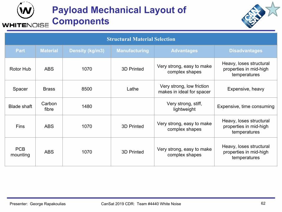
Part Material Density (kg/m3) Manufacturing Advantages Disadvantages
Rotor Hub ABS 1070 3D Printed Very strong, easy to make complex shapes
Heavy, loses structural properties in mid-high
temperatures
Spacer Brass 8500 Lathe Very strong, low friction makes in ideal for spacer Expensive, heavy
Blade shaft Carbon fibre 1480 Very strong, stiff,
lightweight Expensive, time consuming
Fins ABS 1070 3D Printed Very strong, easy to make complex shapes
Heavy, loses structural properties in mid-high
temperatures
PCB mounting ABS 1070 3D Printed Very strong, easy to make
complex shapes
Heavy, loses structural properties in mid-high
temperatures
CanSat 2019 CDR: Team #4440 White NoisePresenter: George Rapakoulias
Payload Mechanical Layout of Components

Container Mechanical Layout of Components
63CanSat 2019 CDR: Team 4440 White Noise
Container has specially shaped pads for retaining the payload in place without stressing any fragile partsContainer technical drawing
All dimensions in millimeters
Presenter: Ioannis Christodoulou

64
Structural Material Selection
Part Material Density (kg/m3) Manufacturing Advantages Disadvantages
Top frame ABS 1070 3D Printed Very strong, easy to make complex shapes
Heavy, loses structural properties in mid-high
temperatures
Rods Carbon fibre 1480 Very strong, stiff,
lightweight Expensive, Hard to shape
Bottom frame ABS 1070 3D Printed Very strong, easy to make
complex shapes
Heavy, loses structural properties in mid-high
temperatures
Landing legs ABS 1070 3D Printed Very strong, easy to make
complex shapes
Heavy, loses structural properties in mid-high
temperatures
Leg rod Carbon fibre 1480 Very strong, stiff,
lightweight Expensive, Hard to shape
Pivot shaft S. Steel 7500 Milling Very strong, elastic Heavy
CanSat 2019 CDR: Team #4440 White Noise
Payload Mechanical Layout of Components
Presenter: Ioannis Christodoulou

65
Payload Release Mechanism
CanSat 2019 CDR: Team 4440 White Noise
Burning Rope Retaining Mechanism
● A plastic rope tied to the container carbon rods in the points indicated on the left will hold the 2 halves together.
● A nickel chrome coil will burn the rope and the 2 container parts will split, releasing the payload
● The coil will be wrapped with heat resistant kapton tape for safety
● A switch will be accesible from one of the holes 1-3.
1
2
3
Rope
Nickel Chrome Coil
Kapton tape
Presenter: Ioannis Christodoulou

66
Container Parachute Release Mechanism
CanSat 2019 CDR: Team 4440 White Noise
Parachute attachment holes
Parachute storage compartment
Parachute will be folded on top of the container in a specially shaped space. When the container exits the rocket it will unfold due to the airflow around it and obtain its designed shape.
Presenter: Ioannis Christodoulou

Structure Survivability
67CanSat 2019 CDR: Team 4440 White Noise
● Regarding the electronics mounting method, we have splitted the circuit into 2 separate PCBs. This enables us to mount them in the lower part of the frame, lowering our CG and protecting them in case of a failure in the frame.
● Both PCBs are mounted with bolts in a bracket that sits in between them. On top of the first board sits an enclosure.
● The rear part of the lower board is exposed to the environment because it will host the pressure sensor
● The enclosure has a hole for the cables from servos to enter.
● For securing electrical connections, special plugs will be used
● An easily accesible battery compartment will be hosted under the PCB boards
Electronics mounting, exploded view
Presenter: Ioannis Christodoulou

Structure Survivability
68CanSat 2019 CDR: Team 4440 White Noise
Shock and acceleration testing
In a first level, test were conducted using finite element analysis tools provided by the CAD software. This is a simulation from the part that connects the blades with the rotor. Stress conditions are under maximum calculated RPM and maximum lift.
In a prototyping level, as described in the descent control chapter, we conducted a drop Test with a prototype cansat using a drone. The design survived with minor damages during landing, but all descent control subsystems were intact. Similar tests will be conducted with our final design. We have also conducted stress tests individually in each subsystem, like in the fins and rotor assembly.
Presenter: Ioannis Christodoulou

Mass Budget
69
Payload Mass Budget
Subassembly Components Material Mass per part(g) Justification
Frame
Connecting rods Carbon fiber 12.00 Estimated
Level 3 Subassembly
Level 3 ABS 8.10 Estimated
Bearings (x2) S. Steel 1.95 Datasheet
Rotor shaft S. Steel 11.20 Estimated
Level 1 Subassembly
Level 1 ABS 18.00 Estimated
Leg assembly(x3)
Retaining ring S. Steel 0.08 Datasheet
Leg shaft S. Steel 3.00 Estimated
Leg end cap TPU rubber 5.00 Estimated
Rod Carbon fiber 2.70 Estimated
Leg joint ABS 3.30 Estimated
Lock pin Steel 0.15 Estimated
Torsion spring Music wire 0.55 Estimated
Lock slice S. Steel 3.50 Estimated
CanSat 2019 CDR: Team #4440 White NoisePresenter: Ioannis Christodoulou

Mass Budget
70
Payload Mass Budget
Subassembly Components Material Mass per part(g) Justification
Rotor
Blade hub ABS 10.0 Estimated
Blade subassembly (x3)
Blade connector ABS 2.5 Estimated
Rotor blade pin S. Steel 1.4 Estimated
Spacer Brass 0.9 Estimated
Torsion spring Music wire 0.6 Estimated
Blade Balsa Wood 12 Estimated
Gimbal Servo Motor (x3) 5 Datasheet
Bracket_1 ABS 2.3 Estimated
Bracket_2 ABS 2.5 Estimated
Pin S. Steel 0.46 Estimated
CanSat 2019 CDR: Team #4440 White NoisePresenter: Ioannis Christodoulou

Mass Budget
71
Payload Mass Budget
Subassembly Components Material Mass per part(g) Justification
Control fins
Fin hub ABS 2.8 Estimated
Fins Frame ABS 12.9 Estimated
Fins assembly (x3)
Ball link (x2) S. Steel 0.4 Estimated
Fin ABS 6.8 Estimated
Fin shaft ABS 2.9 Estimated
Ball link rod ABS 0.16 Estimated
Servo Motor 5 Datasheet
Servo arm ABS 0.18 Estimated
Spring Music Wire 0.6 Estimated
Others All bolts 15 Estimated
Electronics cover 3.7 Estimated
CanSat 2019 CDR: Team #4440 White NoisePresenter: Ioannis Christodoulou

Mass Budget
72
Container Mass Budget
Subassembly Components Material Mass per part(g) Justification
Container
Upper cap (x2) ABS 15 Estimated
Bottom cap (x2) ABS 12 Estimated
Connecting rods (x6) Carbon fiber 3 Estimated
Walls (x2) Plywood 15 Estimated
Lower pads (x3) ABS 5.5 Estimated
Top Pads (x3) ABS 0.6 Estimated
Hinges assembly (x2)
Body 1 (x2) ABS 2.2 Estimated
Axle S. Steel 0.5 Estimated
Torsion springs (x2)
Music wire 0.2 Estimated
CanSat 2019 CDR: Team #4440 White NoisePresenter: Ioannis Christodoulou

Mass Budget
73
Payload Electronics Mass Budget
Component Mass (g) Justification
Teensy 3.2 3 Datasheet
Adafruit Ultimate GPS 8.5 Datasheet
Adafruit BNO055 3 Datasheet
Adafruit BMP280 1.3 Datasheet
Adafruit Camera 2.8 Datasheet
Hall Effect Sensor - US5881 x2 0.12 x2 Datasheet
ATtiny85 0.5 Datasheet
XBee S2C Pro 4 Datasheet
Payload Antenna 1.2 Datasheet
Real Time Clock - DS1337C 0.7 Datasheet
Coin Cell Battery - BR1225 0.8 Datasheet
CanSat 2019 CDR: Team #4440 White NoisePresenter: Ioannis Christodoulou

Mass Budget
74
Payload Electronics Mass Budget
Component Mass (g) Justification
Coin Cell Battery Holder 0.58 Datasheet
Buzzer - 95dB 12mm 2.048kHz 1.4 Datasheet
5V Step Up Regulator 0.5 Estimate
Power Switch 0.5 Estimate
LED Light 0.01 Estimate (SMD Package)
Nichrome Wire 0.005 Datasheet/Estimate
Voltage Divider 0.01 Estimate (SMD Package)
3.6V Lithium Battery 18.8 Datasheet
PCBs 19.9 Estimate
Other (Connectors, Pins, etc) 10 Estimate
Total 77.75
CanSat 2019 CDR: Team #4440 White NoisePresenter: Ioannis Christodoulou

Mass Budget
75
Subassembly total weight Weight (g)
Frame 108.04
Rotor 62.2
Gimbal 20.26
Fins 65.02
Container 129.10
Bolts and nuts 15.00
Electronics 77.75
Total 477.37
Margin 32.63
Sources of errors: ● Density of 3D printer filament may vary slightly
from CAD material library value● Glue has not been added to the total weight
We have reduced the total weight of our design from 501 to 477.37 g . In order to reduce weight even more we can:
● Decrease infill density in 3D printed parts. All masses calculated with 100% density in CAD. Lowering the infill density up to 50% while using honeycomb patterns has very small effect on rigidity.
● Consider using different materials and manufacturing methods for some key parts
CanSat 2019 CDR: Team #4440 White NoisePresenter: Ioannis Christodoulou

76
Communication and Data Handling (CDH) Subsystem Design
Dimitrios BraliosSpyridon Pavlatos
CanSat 2019 CDR: Team 4440 White Noise

77
CDH Overview
CanSat 2019 CDR: Team 4440 White NoisePresenter: Dimitrios Bralios
Payload Processor Teensy 3.2
Real Time Clock DS1337C
Payload Antenna FXP70 Freedom 2.4Ghz
Payload Radio XBee S2C Pro

CDH Changes Since PDR
78CanSat 2019 CDR: Team 4440 White NoisePresenter: Dimitrios Bralios
Component PDR CDR Rationale
Real Time Clock DS1337 DS1337C Contains an integrated oscillator, eliminating the need for an external.
Details of changes are discussed in subsequent slides.
79
CDH Requirements
CanSat 2019 CDR: Team 4440 White NoisePresenter: Dimitrios Bralios
No Requirement PriorityVM
A I T D
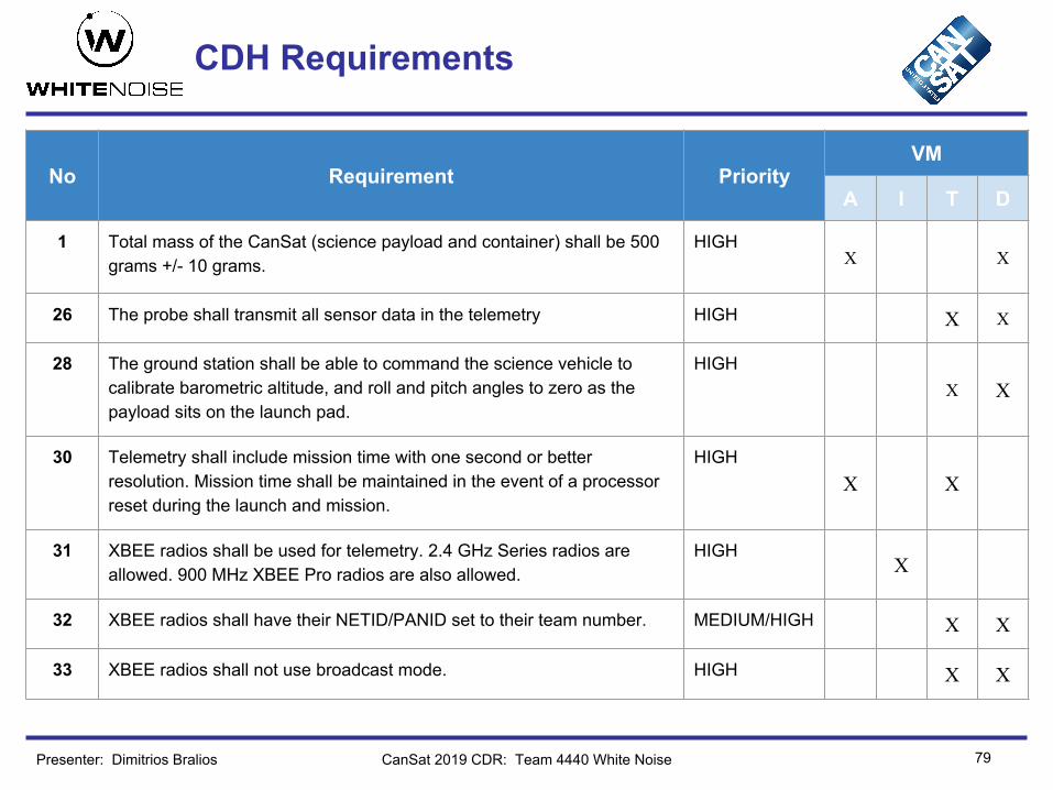
1 Total mass of the CanSat (science payload and container) shall be 500 grams +/- 10 grams.
HIGHX X
26 The probe shall transmit all sensor data in the telemetry HIGH X X
28 The ground station shall be able to command the science vehicle to calibrate barometric altitude, and roll and pitch angles to zero as the payload sits on the launch pad.
HIGHX X
30 Telemetry shall include mission time with one second or better resolution. Mission time shall be maintained in the event of a processor reset during the launch and mission.
HIGHX X
31 XBEE radios shall be used for telemetry. 2.4 GHz Series radios are allowed. 900 MHz XBEE Pro radios are also allowed.
HIGHX
32 XBEE radios shall have their NETID/PANID set to their team number. MEDIUM/HIGH X X
33 XBEE radios shall not use broadcast mode. HIGH X X

80
CDH Requirements
CanSat 2019 CDR: Team 4440 White NoisePresenter: Dimitrios Bralios
No Requirement PriorityVM
A I T D
42The flight software shall maintain a count of packets transmitted, which shall increment with each packet transmission throughout the mission. The value shall be maintained through processor resets.
HIGHX X
47An audio beacon is required for the probe. It may be powered after landing or operate continuously.
HIGHX
48The audio beacon must have a minimum sound pressure level of 92 dB, unobstructed.
MEDIUMX X
Bonus 5
The direction the camera is pointed relative to earth’s magnetic north shall be included in the telemetry.
MEDIUMX

81
Payload Processor & Memory Selection
Memory and storage• The software state as well as the packet counter will be saved on the non-volatile EEPROM memory.
Enabling recovery from processor resets. • Video recorded by the camera will be saved on the onboard micro SD card.• Telemetry packets sent will not be saved by the flight processor, because of the weight, power and size
cost of having another onboard SD card. NotesProgramming is done using the Arduino IDE.Uses a 32 bit ARM processor.
CanSat 2019 CDR: Team 4440 White NoisePresenter: Dimitrios Bralios
Component Power Boot Time
Clock Speed Data Interfaces Memory Mass Cost
Teensy 3.2 34mA x 3.6V 5ms 72MHz
Digital I/O: 34PWM: 12Analog In: 21
Serial: 3SPI: 1I2C: 2
EEPROM: 2KBFlash: 256KBRAM: 64KB
3g 17.40 €

Payload Real-Time Clock
82CanSat 2019 CDR: Team 4440 White NoisePresenter: Dimitrios Bralios
Component Power Crystal Frequency Accuracy Interface Weight Cost
DS1337C 150 μΑ x3V 32768 Hz 10 ppm I2C <3g
(including battery) 2.41€
Sample Data Format: 3:45:40 29 3 2019 (Hours, Minutes, Seconds, Day, Month, and Year)Hardware real-time clockA dedicated 3V coin cell battery will power the real-time clock, making it reset tolerant. The Teensy microprocessor can read the time using the I2C interface, with the help of the Teensy time library. Note: An error of 10 ppm is equivalent to approximately 1 minute per 2 months. Calibration can be performed with the help of the Teensy library. DS1337 was replaced by DS1337CRationale
• The DS1337C contains an integrated oscillator with good accuracy, eliminating the need for an external.
• No other difference than slightly larger size, because of the integrated oscillator.

83
Payload Antenna Selection
Rationale : • High gain• Low weight & small size• Low VSWR
CanSat 2019 CDR: Team 4440 White Noise
Antenna Type Gain Polarization VSWR Dimensions & Weight Connector Cost
FXP70 Freedom 2.4GHz
Flex 5dBi Vertical,horizontal ≤1.5:127x 25 mm
1.2g U.FL 2,93 €
YZ Plane XY Plane XZ Plane
Presenter: Spyridon Pavlatos

84
Payload Radio Configuration
Rationale:• Lower transmit current• Sufficient transmit power• Lower cost• 900 MHz is allocated to mobile networks and we cannot conduct tests on this frequency
Connector: U.FL.
CanSat 2019 CDR: Team 4440 White Noise
Radio Operating Frequency
Transmit Current
Receive Current
Transmit Power Sensitivity RF Data
Rate Cost
XBee S2C Pro 2.4GHz 120 mA @
3.3 VDC31 mA @ 3.3
VDC63 mW
(+18 dBm) -101 dBm 250 Kbps 25.21 €
Presenter: Spyridon Pavlatos
85
Payload Radio Configuration
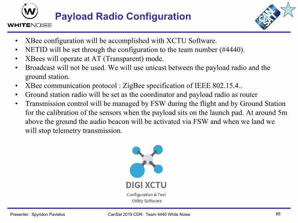
• XBee configuration will be accomplished with XCTU Software.• NETID will be set through the configuration to the team number (#4440).• XBees will operate at AT (Transparent) mode.• Broadcast will not be used. We will use unicast between the payload radio and the
ground station.• XBee communication protocol : ZigBee specification of IEEE 802.15.4..• Ground station radio will be set as the coordinator and payload radio as router• Transmission control will be managed by FSW during the flight and by Ground Station
for the calibration of the sensors when the payload sits on the launch pad. At around 5m above the ground the audio beacon will be activated via FSW and when we land we will stop telemetry transmission.
CanSat 2019 CDR: Team 4440 White NoisePresenter: Spyridon Pavlatos

86
Payload Telemetry Format
• Upon powering up, the CanSat probe shall collect the required telemetry at a 1 Hz sample rate (bursts). The telemetry data shall be transmitted with ASCII comma separated fields followed by a carriage return in the following format (matching the Competition Guide requirements) :
Presenter: Spyridon Pavlatos CanSat 2019 CDR: Team 4440 White Noise
<TEAM ID>,<MISSION TIME>,<PACKET COUNT>,<ALTITUDE>,<PRESSURE>, <TEMP>,<VOLTAGE>,<GPS TIME>,<GPS LATITUDE>,<GPS LONGITUDE>,<GPS ALTITUDE>,<GPS_SATS>,<PITCH>,<ROLL>,<BLADE SPIN RATE>,<SOFTWARE STATE>,<BONUS DIRECTION>
• Example frame:
4440,55,55,375.3,10112,27.5,3.71,14:34:12,37.9790,23.7843,640.5,12,11,13,2340,deployed,5
• The received probe telemetry for the entire mission will be saved on the ground station computer as a comma separated value (.csv) file named “Flight_4440.csv” (matching the Competition Guide requirements).

87
Payload Telemetry Format
<TEAM ID> is the assigned team identification.<MISSION TIME> is the time since initial power up in seconds.<PACKET COUNT> is the count of transmitted packets, which is to be maintained through processor reset.<ALTITUDE> is the altitude in units of meters and must be relative to ground level. The resolution must be 0.1 meters.<PRESSURE> is the measurement of atmospheric pressure in units of pascals. The resolution must be 1 pascals.<TEMP> is the sensed temperature in degrees C with one tenth of a degree resolution.<VOLTAGE> is the voltage of the CanSat power bus. The resolution must be 0.01 volts.<GPS TIME> is the time generated by the GPS receiver. The time must be reported in 11 UTC and have a resolution of a
second.<GPS LATITUDE> is the latitude generated by the GPS receiver in decimal degrees with a resolution of 0.0001 degrees.<GPS LONGITUDE> is the longitude generated by the GPS receiver in decimal degrees with a resolution of 0.0001 degrees.<GPS ALTITUDE> is the altitude generated by the GPS receiver in meters above mean sea level with a resolution of 0.1
meters.<GPS SATS> is the number of GPS satellites being tracked by the GPS receiver. This must be an integer number.<PITCH> is the tilt angle in the pitch axis in degrees. The resolution must be 1 degree. <ROLL> is the tilt angle of the roll axis in degrees. The resolution must be 1 degree.<BLADE SPIN RATE> is the rate the auto-gyro blades spin relative to the science payload. The units must be in revolutions
per minute (rpm). The resolution must be 1 rpm.<SOFTWARE STATE> is the operating state of the software. (boot, idle, launch detect, deploy, etc.).<BONUS DIRECTION> is the direction the camera is pointed relative to earth’s magnetic north specified in degrees.
CanSat 2019 CDR: Team 4440 White NoisePresenter: Spyridon Pavlatos

88
Container Processor & Memory Selection
Presenter: Dimitrios Bralios CanSat 2019 CDR: Team 4440 White Noise
The container will not have any electronics.

89
Electrical Power Subsystem Design
Dimitrios Bralios
CanSat 2019 CDR: Team 4440 White Noise

90
EPS Overview
CanSat 2019 CDR: Team 4440 White NoisePresenter: Dimitrios Bralios
3.6V Lithium Ion Battery
3.6V FENIX ARB-L16-700UP 16340
5V Step Up Regulator
Pololu 5V Step-Up Regulator U1V11F5
3.3V Regulator
Teensy’s onboard regulator
3V Coin Cell Battery
Panasonic BR1225

EPS Changes Since PDR
Details of changes are discussed in subsequent slides.
91CanSat 2019 CDR: Team 4440 White NoisePresenter: Dimitrios Bralios
Component PDR CDR Rationale
3.3V Regulator LM3671 Teensy’s onboard regulator
Saves weight and spaceFits requirements
Coin Cell Battery N/A Panasonic BR1225
Small size and high capacityFits requirements

92
EPS Requirements
CanSat 2019 CDR: Team 4440 White NoisePresenter: Dimitrios Bralios
No Requirement PriorityVM
A I T D
1Total mass of the CanSat (science payload and container) shall be 500 grams +/- 10 grams.
HIGH X
13All electronic components shall be enclosed and shielded from the environment with the exception of sensors.
HIGH X X
16All electronics shall be hard mounted using proper mounts such as standoffs, screws, or high performance adhesives.
HIGH X X
45The probe must include an easily accessible power switch that can be accessed without disassembling the cansat and in the stowed configuration.
HIGH X X
46The probe must include a power indicator such as an LED or sound generating device that can be easily seen without disassembling the cansat and in the stowed state.
HIGH X X
47An audio beacon is required for the probe. It may be powered after landing or operate continuously.
HIGH X

93
EPS Requirements
CanSat 2019 CDR: Team 4440 White NoisePresenter: Dimitrios Bralios
No Requirement PriorityVM
A I T D
48The audio beacon must have a minimum sound pressure level of 92 dB, unobstructed.
MEDIUM X X
49Battery source may be alkaline, Ni-Cad, Ni-MH or Lithium. Lithium polymer batteries are not allowed. Lithium cells must be manufactured with a metal package similar to 18650 cells.
HIGH X X
50An easily accessible battery compartment must be included allowing batteries to be installed or removed in less than a minute and not require a total disassembly of the CanSat.
HIGH X X
51Spring contacts shall not be used for making electrical connections to batteries. Shock forces can cause momentary disconnects.
HIGH X
55Payload/Container shall operate for a minimum of two hours when integrated into rocket.
HIGH X X X
Bonus 1
A video camera shall be integrated into the science payload to record the descent after being released from the container.
MEDIUM X

94
Payload Electrical Block Diagram
CanSat 2019 CDR: Team 4440 White NoisePresenter: Dimitrios Bralios

Payload Power Source
95CanSat 2019 CDR: Team 4440 White NoisePresenter: Dimitrios Bralios
Battery Voltage Capacity Max Discharge Current Size Weight Cost
FENIX ARB-L16-700UP 16340 3.6V 2.52 Wh
(700mAh)3A
2.5A (stable) ⌀16.0 x 35.0mm 18.8g 6.00 €
5V Step Up Regulator Voltage Range
Efficiency at 3.6V
Max Output Current Size Weight Cost
Pololu 5V Step-Up Regulator U1V11F5 0.5 - 5.5V 85% 1.2A 12mm x 15mm 0.6g 7.45 €
Coin Cell Battery Voltage Capacity
Panasonic BR1225 3V 48 mAh
Power source descriptionThe CanSat has one 3.6V Lithium Ion battery (neither in series nor parallel configuration) which powers most of the components. The servo motors are powered by a 5V step up regulator, which is powered by the Lithium Ion battery. The XBee, ATtiny85 and buzzer will be powered at 3.3V by Teensy’s onboard 3.3V regulator, which can give up to 250 mA. Finally, the real-time clock will be powered by a dedicated 3V coin cell battery.Voltage Levels: 5V, 3.6V, 3.3V, 3V
3.3V Regulator Voltage Max Output Current
Teensy’s onboard regulator
3.3V 250 mA

Payload Power Source
96CanSat 2019 CDR: Team 4440 White NoisePresenter: Dimitrios Bralios
NotesAs shown in the following slides the power sources have more than enough capacity to power all of the CanSat’s components.Finally, the maximum current draw by the components never exceeds the 3A limit of the lithium ion battery. While the components powered by the regulators never exceed the current draw limits (1.2A for the 5V step up and 250mA for the 3.3V regulator)
Changes since PDRThe LM3671 3.3V Regulator was replaced by Teensy’s onboard regulatorRationale:
• We save weight and space• The components draw substantially less current than the 250 mA limit
The coin cell battery chosen is the Panasonic BR1225Rationale:
• Fits the requirements perfectly.• Has very high capacity, being able to power the real-time clock for up to 320 hours.

97
Payload Power Budget
CanSat 2019 CDR: Team 4440 White NoisePresenter: Dimitrios Bralios
Component Current(mA)
Voltage(V)
Power(mW)
Duty Cycle(sec)
Power Consumption (mWh) Source
Teensy 3.2 34 3.6 122.4 7200 244.8 Datasheet
Adafruit Ultimate GPS 20 3.6 72 7200 144 Datasheet
Adafruit BNO055 12.3 3.6 44.28 7200 88.56 Datasheet
Camera 110 3.6 396 100 11 Datasheet
BMP280 0.1 3.6 0.36 7200 0.72 Datasheet/Estimate
US5881 x2 2.5 3.6 18 7200 36 Datasheet
Voltage Divider 0.1 3.6 0.36 7200 0.72 Estimate
XBee S2C Pro (idle/transmitting)
31/120 3.3 111.6/
4327200/100
222.2/12 Datasheet
ATtiny85 5 3.3 18 7200 36 Datasheet
Buzzer 35 3.3 126 600 21 Datasheet
DS1337C 0.15 3 0.45 7200 0.9 Datasheet
Servo Motor x6 150 5 5294 50 73.5 Measurement
Nichrome Wire 700 3.6 2520 5 3.5 Measurement

98
Payload Power Budget
CanSat 2019 CDR: Team 4440 White NoisePresenter: Dimitrios Bralios
Total Power Consumed (Wh)
Total Capacity Required(mAh)
Available Capacity(Wh) Margin (Wh)
0.89(894 mWh) 249 2.52 1.63
Power Source: Lithium Ion Battery
Power Source: Coin Cell Battery
Total Power Consumed
(mWh)
Available Capacity(mWh)
Margin (mWh)
0.9 48 47.1
NotesPower of components powered by the 3.3V Regulator are calculated using the following equation, because of the heat losses.
Power of the components powered by the 5V Step Up Regulator are calculated as follows, because of the 85% efficiency.
ConclusionThe power sources are capable of powering all the components for the required amount of time.

99
Container Electrical Block Diagram
CanSat 2019 CDR: Team 4440 White NoisePresenter: Dimitrios Bralios
The container will not have any electronics.

Container Power Source
100Presenter: Dimitrios Bralios CanSat 2019 CDR: Team 4440 White Noise
The container will not have any electronics.

101
Container Power Budget
Presenter: Dimitrios Bralios CanSat 2019 CDR: Team 4440 White Noise
The container will not have any electronics.

102
Flight Software (FSW) Design
Miltiadis Stouras
CanSat 2019 CDR: Team 4440 White Noise

103
FSW Overview
Presenter: Miltiadis Stouras CanSat 2019 CDR: Team 4440 White Noise
Overview of FSW tasks:• Correctly calibrate sensors• Activate mechanisms in the correct time• Ensure telemetry’s frequency is 1Hz• Bypass minor sensor failures• Design a software architecture such that the processor can fully
recover from a sudden power loss that might occur in any time during the mission and for arbitrary duration
Programming languages: For the flight software development, our team will use the Arduino programming language as it offers a simple interface to program microcontrollers and also comes with a great variety of open source libraries for the sensors we selected.
Development Environments: The IDE used is Atom, because it is user-friendly, it has many packages for the Arduino programming language and can also be used with a Linter program that ensures code readability. We are also using Teensy Loader & Arduino IDE for uploading code to our microcontrollers

FSW Changes Since PDR
• There have not been any major changes.• Our team switched from C programming language to Arduino
programming language, which is a subset of C/C++, since it offers a more easy-to-use interface in order to program the microcontroller we have selected.
104CanSat 2019 CDR: Team 4440 White NoisePresenter: Miltiadis Stouras

105
FSW Requirements
CanSat 2019 CDR: Team 4440 White Noise
No Requirement PriorityVM
A I T D
9 The container shall release the payload at 450 meters +/- 10 meters. HIGH X X X
28The ground station shall be able to command the science vehicle to calibrate barometric altitude, and roll and pitch angles to zero as the payload sits on the launch pad.
HIGHX X X X
30Telemetry shall include mission time with one second or better resolution. Mission time shall be maintained in the event of a processor reset during the launch and mission.
HIGHX X X
42The flight software shall maintain a count of packets transmitted, which shall increment with each packet transmission throughout the mission. The value shall be maintained through processor resets.
HIGHX X X
47An audio beacon is required for the probe. It may be powered after landing or operate continuously.
HIGHX X
53The GPS receiver must use the NMEA 0183 GGA message format. HIGH
X X X
Presenter: Miltiadis Stouras

106
FSW Requirements
CanSat 2019 CDR: Team 4440 White Noise
No Requirement PriorityVM
A I T D
Bonus 1
A video camera shall be integrated into the science payload to record the descent after being released from the container.
MEDIUMX X X X
Presenter: Miltiadis Stouras

107
Payload CanSat FSW State Diagram
CanSat 2019 CDR: Team 4440 White Noise
Software States:● Launch (0)● Not Deployed (1)● Deployed (2)● Landed (3)
[TC] (Transition Counter) is the number of positive checks remaining for a state transition
Rationale behind TC: We do not want to take major decisions based on a single measurement
Find State, Telemetry and System Recovery are analyzed in the next slide
Presenter: Miltiadis Stouras

108
Payload CanSat FSW State Diagram
CanSat 2019 CDR: Team 4440 White Noise
For System Recovery, we are saving the following data in Teensy’s non-volatile memory (EEPROM) :
● prevState: The last known software state the processor has been in. It takes values 0,1,2 or 3 and before the mission it will be initialized to our team’s ID.
● isNichromeBurned: A boolean variable that is true if and only if the payload has been deployed. It will be initialized to false.
● packetCount: The running count of the packets transmitted throughout the mission.
Find State, using EEPROM and on the spot measurements, can determine in which state the software should continue if we experience a processor reset. Notice that just using EEPROM’s prevState would not be enough in a case where we should have transitioned to another state while being powered off.
Presenter: Miltiadis Stouras

109
Container CanSat FSW State Diagram
CanSat 2019 CDR: Team 4440 White Noise
Container will not have any electronics.
Presenter: Miltiadis Stouras

110
Software Development Plan
CanSat 2019 CDR: Team 4440 White Noise
For version control & team cooperation, we use Git & GitHub.
The flight software is tested on experiments (drop tests, measurements in extreme conditions, processor reset simulations etc.) to ensure it is properly working.
Progress: ● Completed the code for every subsystem.● Tested every subsystem independently.● Completed the code for blade optimization.● Completed the code for the gimbal mechanism● Performed basic tests for the gimbal mechanism.
To be done:● Test all subsystems together.
Presenter: Miltiadis Stouras

111
Ground Control System (GCS) Design
Miltiadis Stouras
CanSat 2019 CDR: Team 4440 White Noise

112
GCS Overview
CanSat 2019 CDR: Team 4440 White NoisePresenter: Miltiadis Stouras

GCS Changes Since PDR
There have not been any changes.
113CanSat 2019 CDR: Team 4440 White NoisePresenter: Miltiadis Stouras

114
GCS Requirements
CanSat 2019 CDR: Team 4440 White Noise
No Requirement PriorityVM
A I T D
28The ground station shall be able to command the science vehicle to calibrate barometric altitude, and roll and pitch angles to zero as the payload sits on the launch pad.
HIGH
X X
29The ground station shall generate a csv file of all sensor data as specified in the telemetry section.
HIGHX X
35Each team shall develop their own ground station. HIGH
X X X
36 All telemetry shall be displayed in real time during descent. HIGH X X X
37All telemetry shall be displayed in engineering units (meters, meters/sec, Celsius, etc.)
HIGHX X
38Teams shall plot each telemetry data field in real time during flight. HIGH
X X X X
Presenter: Miltiadis Stouras
115
GCS Requirements
CanSat 2019 CDR: Team 4440 White Noise
No Requirement PriorityVM
A I T D
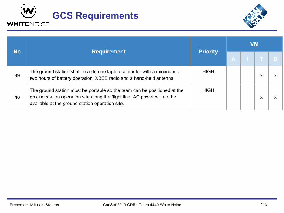
39The ground station shall include one laptop computer with a minimum of two hours of battery operation, XBEE radio and a hand-held antenna.
HIGHX X
40The ground station must be portable so the team can be positioned at the ground station operation site along the flight line. AC power will not be available at the ground station operation site.
HIGHX X
Presenter: Miltiadis Stouras

GCS Design
116CanSat 2019 CDR: Team 4440 White Noise
● Duration: 3h on laptop’s battery● Overheating: To protect our ground
station from overheating, we will use a sun umbrella and a fan-cooling base for the laptop.
● Auto-update mitigation: We will use Ubuntu Linux 18.04 LTS with auto- update turned off.
Presenter: Miltiadis Stouras

GCS Software
117CanSat 2019 CDR: Team 4440 White Noise
Software packages used:● Server Side:
Node.js,Express.js,Socket.io
● Front-end:ReactReduxRxJS
Incoming data flow:
Command flow:Progress since PDR:The Ground Station Software is completed, has been tested and is fully operational.
Presenter: Miltiadis Stouras

GCS Software
118CanSat 2019 CDR: Team 4440 White NoisePresenter: Name goes here

119
GCS Antenna
CanSat 2019 CDR: Team 4440 White Noise
Antenna Type Gain Polarization VSWR H-V Beamwidth Mounting Cost
ANT-2YAG16-SMA Yagi-directional 16dBi Vertical,
horizontal ≤2.0:1 23°/23° hand-held 53.67 €
Rationale: • High gain• Lower cost• Low VSWR• Hand-held we can direct it easily
Radiation pattern:
*we only consider the horizontal plane radiation pattern, because we will aim the antenna by hand
Presenter: Spyridon Pavlatos

120
GCS Antenna
CanSat 2019 CDR: Team 4440 White Noise
• Link Budget: where
• We can assume that are approximately 10dBm together and is 0.• Free Space Path Loss equation derived from Friis transmission equation :
where f=2.4GHz, d=1.25km and c speed of light.• Therefore, and • XBee sensitivity -101dBm Safe margin ~ 28dBm for d=1.25km
Presenter: Spyridon Pavlatos

121
CanSat Integration and Test
Miltiadis Stouras
CanSat 2019 CDR: Team 4440 White Noise

Team LogoHere
(If You Want)
122
CanSat Integration and Test Overview
CanSat 2019 CDR: Team 4440 White Noise
In order to make sure everything works as designed a series of tests will be/have been conducted: ● All subsystems have been tested individually with prototypes. More tests will be
conducted when the final ones are constructed.● After all subsystems are assembled together tests will be done in order to
ensure that operation of each subsystem doesn’t affect others in any non predicted manner. Some of those tests have already been carried out in the test platform.
● The design during testing will be subjected to worse or similar conditions, than during the mission.
● Testing design early is key for having a high end result. Tests will point out weaknesses in the design and sufficient time must be available for design tweaks.
Presenter: Miltiadis Stouras

Team LogoHere
(If You Want) Subsystem Level Testing Plan
123CanSat 2019 CDR: Team 4440 White Noise
Sensors Subsystem Testing Plans
Components Tests
Air Pressure ● Verify the validity of the measurements by measuring altitude at locations where altitude is known.
Air Temperature ● Verify the validity of the measurements by measuring temperature and comparing to other thermometers.
GPS ● Verify the validity of the position measurements by comparison to other GPS devices with the help of Google Maps.
Pitch and Roll ● Verify the validity of the pitch and roll measurements by rotating to specific Euler angles.
Blade Spin Rate● Verify the validity of the blade spin rate measurements by comparison to an optical
tachometer.● Verify that the sensor module provides correct measurements with the expected accuracy.
Voltage Sensor ● Verify that the voltage level measured corresponds to the voltage level of the battery powering the CanSat.
Camera ● Verify that the module works as specified, outputting 640x480, 30fps color video.
Presenter: Miltiadis Stouras

Team LogoHere
(If You Want) Subsystem Level Testing Plan
124CanSat 2019 CDR: Team 4440 White Noise
EPS Subsystem
Tests
● Verify current draw stated on the datasheet of all the electronics at different stages of the mission.
● Verify that the CanSat can operate for at least two hours on internal power.
● Verify the stated efficiency of the 5V step up regulator by measuring the output as well as the input current, powering the servo motors.
● Verify that the battery can provide the peak current level (1.5A) without major consequences on the battery capacity. ● Verify that the current draw of the components powered by the Teensy’s onboard regulator is under 250mA.
● Test the ability of the nichrome wire to cut the string that holds the container closed. While, verifying the current draw is the expected.
● Verify the voltage levels are as expected under all possible loads and all components are powered.
● Verify that the CanSat operates using the umbilical power source.
Presenter: Miltiadis Stouras

Team LogoHere
(If You Want) Subsystem Level Testing Plan
125CanSat 2019 CDR: Team 4440 White Noise
Radio Communication Subsystem
Components Tests
Antennas● Range test to ensure that antenna amplifies the signal enough, so that the communication
can be achieved in distances even bigger than the estimated distance for the launch day.
XBee radio
● Configuration test. Set the parameters to match the Mission Requirements : NETID, unicast mode.
● Test communication between the 2 XBees.
CDH Subsystem
Components Tests
Processor and Memory ● Ensure the processor is fast enough to collect all the measurements and perform the necessary calculations for the control system.
Real Time Clock ● Verify that we can correctly calibrate the real time clock and the time drift has the expected value
Camera SD card ● Ensure the SD card storage is enough to store the video recorded during the descent.
Presenter: Miltiadis Stouras

Team LogoHere
(If You Want) Subsystem Level Testing Plan
126CanSat 2019 CDR: Team 4440 White Noise
FSW
Tests
● Processor Resets: Simulate all possible processor shut downs (in any state of the mission) and check that state recovery functions works properly.
● Ensure that it is not possible to be stuck in a state after reset.
● Ensure that all sensors’ accuracy is being considered in condition checks.
● Verify state transitions are done correctly.● Verify software state is correct after giving any possible input.
● Test software using corrupted sensor data (produced randomly) to check its ability to handle failures.
● Check that sensors’ refresh rates are sufficient for the active control system.
● Test the code that drives the servos of the gimbal mechanism.
Presenter: Miltiadis Stouras
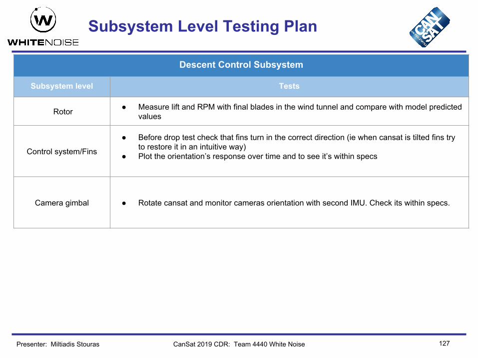
Team LogoHere
(If You Want) Subsystem Level Testing Plan
127CanSat 2019 CDR: Team 4440 White Noise
Descent Control Subsystem
Subsystem level Tests
Rotor ● Measure lift and RPM with final blades in the wind tunnel and compare with model predicted values
Control system/Fins
● Before drop test check that fins turn in the correct direction (ie when cansat is tilted fins try to restore it in an intuitive way)
● Plot the orientation’s response over time and to see it’s within specs
Camera gimbal ● Rotate cansat and monitor cameras orientation with second IMU. Check its within specs.
Presenter: Miltiadis Stouras

Team LogoHere
(If You Want) Subsystem Level Testing Plan
128CanSat 2019 CDR: Team 4440 White Noise
Mechanical Subsystem
Subsystem level Tests
Rotor ● Verify that rotor is balanced and doesn’t vibrate when rotating in high speeds● Verify alignment in bearings and measure torque transmitted to the frame through friction● Verify joints can withstand forces in all scenarios ie. rapid change in orientation, vibrations
Fins ● Verify that all fins are aligned when in neutral position● Verify that servos have the required response when in full load conditions
Landing gear ● Make sure joints can withstand all scenarios
Camera Gimbal ● Make sure gimbal moves in the full servo range.
Container ● Ensure that springs on the container separate the 2 parts faster than Payload Deploys. This will prevent any malfunctions during deployment
Presenter: Miltiadis Stouras

Team LogoHere
(If You Want) Integrated Level Functional Test Plan
129CanSat 2019 CDR: Team 4440 White Noise
Test type Tests
Sensors● Verify that the sensors are calibrated providing the correct measurements.● Verify that the sensors provide measurements with the expected accuracy and resolution in
the expected range.● Ensure the sampling rate is at least 1Hz
Mechanical ● Ensure that all mechanisms are working as designed when all parts are assembled ● Ensure that glued parts are rigidly connected and can withstand acceleration requirements● Ensure frame won’t deform in any scenario causing fragile parts to undergo stresses● Verify that it all scenarios landing legs deformation will not cause camera to touch the
ground. ● Free fall and parachute drop tests will be conducted extensively● Conduct vibration test
Descent Control
● Perform drop test from drone to check autogyro mechanism works as designed● Measure vibrations caused from poorly balanced rotor and gyroscopic effects during
descent to see if they exceed safe limit
Presenter: Miltiadis Stouras

Team LogoHere
(If You Want) Environmental Test Plan
130CanSat 2019 CDR: Team 4440 White Noise
Drop Test procedure:
1. Attach parachute to a ceiling bolt using a non stretching cord.
2. Let the CanSat fall from ceiling height, and measure acceleration when the cord strains.
3. Quick Check for damage.4. Repeat for various lengths acceleration
values.5. Release CanSat.6. Check for: Power Loss, damage, detached
parts, parachute fail etc.
Data must be transmitted through the procedure from the CanSat to the GCS.
Thermal Test procedure:We are planning to construct a thermal chamber that can accomodate our CanSat, following the steps described in the mission guide. More specifically :
1. A temperature sensor will be placed in the chamber and for temperature control. Data will be sent to an arduino that will be out of the chamber.
2. We will start the heating with a hairdryer connected to the chamber.
3. When temp. reaches 60℃ we turn of the heat source via a relay.
4. If temperature falls below 55℃, we turn on the heat source.
5. Temperature will be maintained between 55℃ and 60℃ for two hours.
6. Get the CanSat out of the chamber.7. Inspect for any kind of damage.
Data must be transmitted through the procedure from the CanSat to the GCS.
Presenter: Miltiadis Stouras

Team LogoHere
(If You Want) Environmental Test Plan
131CanSat 2019 CDR: Team 4440 White Noise
Vibration Test Procedure:
We plan to use an orbit sander for this test.1. Secure the sander upside down, via a
bench vise.2. Secure CanSat on the moving pad of the
sander.3. Power on the CanSat.4. Verify that telemetry works.5. Power on the sander.6. When sander reaches full speed, wait 5 or
more seconds.7. Turn of the sander.8. Inspect for damage.9. Repeat steps 5-7.
Data must be transmitted through the procedure from the CanSat to the GCS.
Fit check:For checking that the cansat will fit inside the rocket’s compartment we will do the following:
1. Measure the container’s outside dimensions and check that they are equal or slightly smaller than designed.
2. 3D print a cylinder with dimensions equal to the rocket’s payload compartment.
3. Check that cansat can easily slide in the 3D printed compartment
Presenter: Miltiadis Stouras

Test Procedures Descriptions
132
Test Proc Test Description Requirements Pass Fail Criteria
1 Measure lift and RPM with final blades in the wind tunnel and compare with model predicted values
2Before drop test check that fins turn in the correct direction (ie when cansat is tilted fins try to restore it in an intuitive way)
3 Measure torque fins can exert on frame and compare them with model predicted ones
4 Verify that all fins are aligned when in neutral position
5 Verify that servos have the required response when in full load conditions
6 Make sure joints can withstand all scenarios
7Ensure that springs on the container separate the 2 parts faster than Payload Deploys. This will prevent any malfunctions during deployment
8 Verify that rotor is balanced and doesn’t vibrate when rotating in high speeds
CanSat 2019 CDR: Team 4440 White NoisePresenter: Miltiadis Stouras
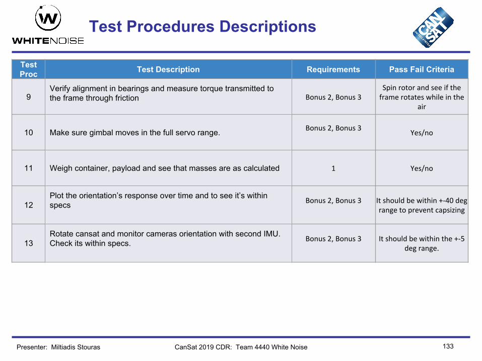
Test Procedures Descriptions
133
Test Proc Test Description Requirements Pass Fail Criteria
9Verify alignment in bearings and measure torque transmitted to the frame through friction
10 Make sure gimbal moves in the full servo range.
11 Weigh container, payload and see that masses are as calculated
12Plot the orientation’s response over time and to see it’s within specs
13Rotate cansat and monitor cameras orientation with second IMU. Check its within specs.
CanSat 2019 CDR: Team 4440 White NoisePresenter: Miltiadis Stouras

Test Procedures Descriptions
134
Test Proc Test Description Requirements Pass Fail Criteria
18 Check that the radio configuration complies with the Mission Guide 31,32,33
XBee’s operating frequency at 2.4 GHz, set
in unicast mode and NETID set to our team
number
19 Antennas (both payload’s and GS’s) range test. 26,28Communication achieved for distances bigger than
1.25km.
20 Verify the CanSat can operate for at least 2 hours on internal power. 55 CanSat is still operational after 2 hours
21 Verify the buzzer reaches the required sound level. 48 Sound level is above 92dB
22 Verify the sensors operate in the expected range with the expected accuracy. 20,21,22,23,24,25
Receive measurement,s within the specified range, at a rate of at least 1Hz.
CanSat 2019 CDR: Team 4440 White NoisePresenter: Miltiadis Stouras
General Comments● We have specified the tests only for the requirements that need testing. The ones
that are evident through demonstration are not included here.
135
Mission Operations & Analysis
Dimitrios Bralios
CanSat 2019 CDR: Team 4440 White Noise

136
Overview of Mission Sequence of Events
Presenter: Dimitrios Bralios CanSat 2019 CDR: Team 4440 White Noise
Roles & Responsibilities
1. Mission Control Officer Iasonas Nikolaou
2.GCS crew Miltiadis Stouras, Spyridon Pavlatos, Marios Papachristou
3.Recovery crew Chariton Charitonidis, George Rapakoulias, Dimitrios Bralios, Neoklis Vaindirlis
4.CanSat crew George Rapakoulias, Dimitrios Bralios, Neoklis Vaindirlis, Ιοannis Christodoulou

137
Overview of Mission Sequence of Events
Presenter: Dimitrios Bralios CanSat 2019 CDR: Team 4440 White Noise
Arrival:● Arrival at the launch location (1,2,3,4)● Ground station set up (2)
Pre-Launch:● Antenna check (2)● Communication check (2,4)● Fit check & mass measurement (4)● Container release mechanism check (4)● Processor’s EEPROM initialized (4)● Inspection of electronics (4)● Turn in CanSat at Check-in (4)
Launch:● Lift-off ● Apogee reached - Container separated from the rocket● Parachute released, container descenting with terminal velocity 20m/s● Payload released at an altitude of 450m

138
Overview of Mission Sequence of Events
Presenter: Dimitrios Bralios CanSat 2019 CDR: Team 4440 White Noise
Mission:● Payload descents with auto-gyro mechanism. Descent rate at 10.5m/s● On-board camera activated● Camera & Payload stabilization through active control● The audio beacon will operate throughout the mission
CanSat Recovery:● Trace CanSat during descent (3)● Find payload (3)● Detach SD card and back-up data (3)
Post-Mission, Data Analysis:● Check video stabilization and quality (2)● Check collected mission data for inconsistencies (2)● Compare observed trajectory with collected mission data (2)

139
Field Safety Rules Compliance
All the Field Safety Rules mentioned in the mission guide will be strictly observed by all team members.
The Mission Operations Manual will be ready before the Flight Readiness Review. During the launch event it will be available in multiple copies in a three ring binder.
The Mission Operation Manual will include detailed instructions of the mission sequence of events discussed in the previous slide, indicating every subteam’s activities at each point during the mission.
CanSat 2019 CDR: Team 4440 White NoisePresenter: Dimitrios Bralios

140
CanSat Location and Recovery
CanSat 2019 CDR: Team 4440 White NoisePresenter: Dimitrios Bralios
CanSat Recovery Strategy:● The Recovery Crew will be tracing the CanSat during descent● The audio beacon will be operating after landing● We will also use payload’s GPS location provided in telemetry, to get a better
estimate of the landing zoneCanSat Color: Both the container and the payload will be Orange so they can easily be spotted in the sky or the field.
CanSat Label: The container will have a label with the following information:
National Technical University of Athens, White NoiseZografou Campus
9, Iroon Polytechniou str15780, Zografou, Attica, [email protected]

Mission Rehearsal Activities
Part of the Mission Operation Manual has already been developed and our team is rehearsing the mission sequence of events, ensuring the mission will proceed as planned.
Specifically, we are focusing on the following procedures• Check of the Ground Control Station• Preparing the CanSat for launch• Loading of the CanSat and final launch preparations• Calibration of the CanSat on the launch platform• Handling of telemetry and analysis of the data• Recovery of the probe, using the audio beacon
141CanSat 2019 CDR: Team 4440 White NoisePresenter: Dimitrios Bralios

142
Requirements Compliance
Dimitrios Bralios
CanSat 2019 CDR: Team 4440 White Noise

Requirements Compliance Overview
143Presenter: Dimitrios Bralios CanSat 2019 CDR: Team 4440 White Noise
Compliance Summary
● All contest requirements have been tested theoretically using simulation methods.
● Most of the tests, during the prototyping stage, have been performed providing valuable results.
● Tests on the final design will be conducted again to ensure compliance to the requirements.
Comply
Partial
No comply
The following table provides details for all contest requirements, their compliance, and their referencing slides Requirements have been marked as per compliance, as suggested in the template:
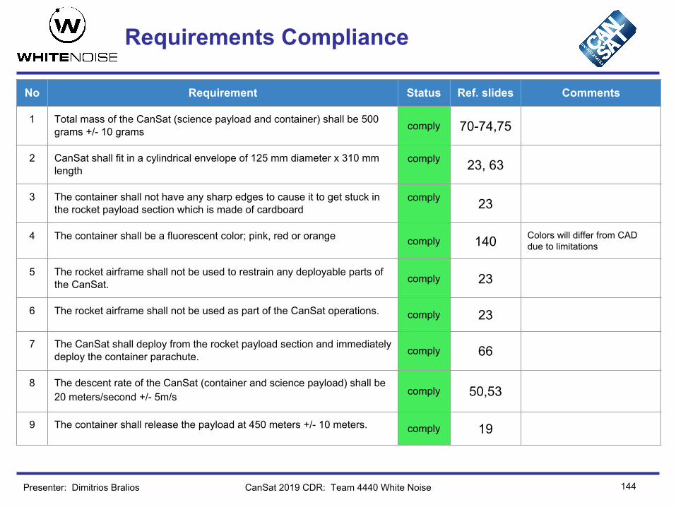
Requirements Compliance
144Presenter: Dimitrios Bralios CanSat 2019 CDR: Team 4440 White Noise
No Requirement Status Ref. slides Comments
1 Total mass of the CanSat (science payload and container) shall be 500 grams +/- 10 grams comply 70-74,75
2 CanSat shall fit in a cylindrical envelope of 125 mm diameter x 310 mm length
comply 23, 63
3 The container shall not have any sharp edges to cause it to get stuck in the rocket payload section which is made of cardboard
comply 23
4 The container shall be a fluorescent color; pink, red or orange comply 140 Colors will differ from CAD due to limitations
5 The rocket airframe shall not be used to restrain any deployable parts of the CanSat. comply 23
6 The rocket airframe shall not be used as part of the CanSat operations. comply 23
7 The CanSat shall deploy from the rocket payload section and immediately deploy the container parachute. comply 66
8 The descent rate of the CanSat (container and science payload) shall be 20 meters/second +/- 5m/s comply 50,53
9 The container shall release the payload at 450 meters +/- 10 meters. comply 19

Requirements Compliance
145Presenter: Dimitrios Bralios CanSat 2019 CDR: Team 4440 White Noise
No Requirement Status Ref. slides Comments
10 The science payload shall descend using an auto-gyro descent control system. comply 19
11 The descent rate of the science payload after being released from the container shall be 10 to 15 meters/second
comply 51,52,53
12 All descent control device attachment components shall survive 30 Gs of shock.
comply 67, 68
13 All electronic components shall be enclosed and shielded from the environment with the exception of sensors. comply 67
14 All structures shall be built to survive 15 Gs of launch acceleration. comply 67, 68
15 All structures shall be built to survive 30 Gs of shock. comply 67, 68
16 All electronics shall be hard mounted using proper mounts such as standoffs, screws, or high performance adhesives. comply 67
17 All mechanisms shall be capable of maintaining their configuration or states under all forces. comply 67, 68
18 Mechanisms shall not use pyrotechnics or chemicals. comply 54-75 Not used

Requirements Compliance
146Presenter: Dimitrios Bralios CanSat 2019 CDR: Team 4440 White Noise
No Requirement Status Ref. slides Comments
19 Mechanisms that use heat (e.g., nichrome wire) shall not be exposed to the outside environment to reduce potential risk of setting vegetation on fire.
comply 65
20 The science payload shall measure altitude using an air pressure sensor. comply 29
21 The science payload shall provide position using GPS. comply 31
22 The science payload shall measure its battery voltage. comply 32
23 The science payload shall measure outside temperature. comply 30
24 The science payload shall measure the spin rate of the auto-gyro blades relative to the science vehicle. comply 34, 35
25 The science payload shall measure pitch and roll comply 33
26 The probe shall transmit all sensor data in the telemetry comply 77,86,87
27 The Parachute shall be fluorescent Pink or Orange comply 140
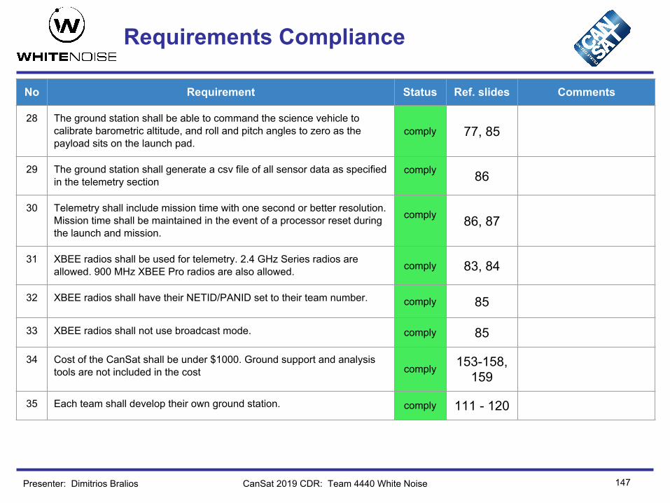
Requirements Compliance
147Presenter: Dimitrios Bralios CanSat 2019 CDR: Team 4440 White Noise
No Requirement Status Ref. slides Comments
28 The ground station shall be able to command the science vehicle to calibrate barometric altitude, and roll and pitch angles to zero as the payload sits on the launch pad.
comply 77, 85
29 The ground station shall generate a csv file of all sensor data as specified in the telemetry section
comply 86
30 Telemetry shall include mission time with one second or better resolution. Mission time shall be maintained in the event of a processor reset during the launch and mission.
comply 86, 87
31 XBEE radios shall be used for telemetry. 2.4 GHz Series radios are allowed. 900 MHz XBEE Pro radios are also allowed. comply 83, 84
32 XBEE radios shall have their NETID/PANID set to their team number. comply 85
33 XBEE radios shall not use broadcast mode. comply 85
34 Cost of the CanSat shall be under $1000. Ground support and analysis tools are not included in the cost comply 153-158,
159
35 Each team shall develop their own ground station. comply 111 - 120
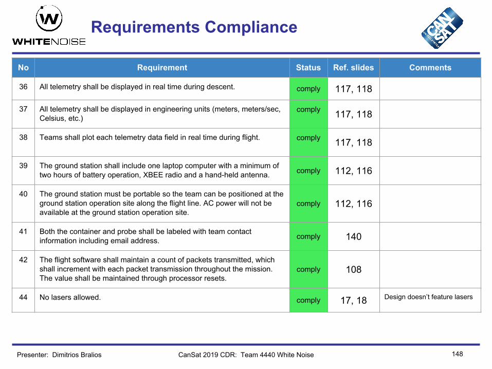
Requirements Compliance
148Presenter: Dimitrios Bralios CanSat 2019 CDR: Team 4440 White Noise
No Requirement Status Ref. slides Comments
36 All telemetry shall be displayed in real time during descent. comply 117, 118
37 All telemetry shall be displayed in engineering units (meters, meters/sec, Celsius, etc.)
comply 117, 118
38 Teams shall plot each telemetry data field in real time during flight. comply 117, 118
39 The ground station shall include one laptop computer with a minimum of two hours of battery operation, XBEE radio and a hand-held antenna. comply 112, 116
40 The ground station must be portable so the team can be positioned at the ground station operation site along the flight line. AC power will not be available at the ground station operation site.
comply 112, 116
41 Both the container and probe shall be labeled with team contact information including email address. comply 140
42 The flight software shall maintain a count of packets transmitted, which shall increment with each packet transmission throughout the mission. The value shall be maintained through processor resets.
comply 108
44 No lasers allowed. comply 17, 18 Design doesn’t feature lasers

Requirements Compliance
149Presenter: Dimitrios Bralios CanSat 2019 CDR: Team 4440 White Noise
No Requirement Status Ref. slides Comments
45 The probe must include an easily accessible power switch that can be accessed without disassembling the cansat and in the stowed configuration.
comply 65, 94
46 The probe must include a power indicator such as an LED or sound generating device that can be easily seen without disassembling the cansat and in the stowed state.
comply 94
47 An audio beacon is required for the probe. It may be powered after landing or operate continuously
comply 94, 140
48 The audio beacon must have a minimum sound pressure level of 92 dB, unobstructed. comply 94 Sparkfun’s PC Mount 12mm
2.048kHz 95dB
49 Battery source may be alkaline, Ni-Cad, Ni-MH or Lithium. Lithium polymer batteries are not allowed. Lithium cells must be manufactured with a metal package similar to 18650 cells.
comply 95 16340 metal package
50 An easily accessible battery compartment must be included allowing batteries to be installed or removed in less than a minute and not require a total disassembly of the CanSat.
comply 67
51 Spring contacts shall not be used for making electrical connections to batteries. Shock forces can cause momentary disconnects. comply 67

Requirements Compliance
150Presenter: Dimitrios Bralios CanSat 2019 CDR: Team 4440 White Noise
No Requirement Status Ref. slides Comments
52 The auto-gyro descent control shall not be motorized. It must passively rotate during descent. comply 38 - 53
53 The GPS receiver must use the NMEA 0183 GGA message format. comply 31
54 The CANSAT must operate during the environmental tests. comply 130, 131
55 Payload/Container shall operate for a minimum of two hours when integrated into rocket. comply 95 - 97,
98
B 1 A video camera shall be integrated into the science payload to record the descent after being released from the container. comply 36
B 2 The camera shall point downward 45 degrees from nadir. comply 48, 61
B 3 It shall be spin stabilized and point in one direction relative to the earth’s magnetic field with a stability of +/- 10 degrees. Direction does not matter as long as it is in one direction.
comply 46, 47
B 4 Video shall be in color with a minimum resolution of 640x480 pixels and 30 frames per second comply 36
B 5 The direction the camera is pointed relative to earth’s magnetic north shall be included in the telemetry. comply 86, 87
151
Management
Dimitrios Bralios
CanSat 2019 CDR: Team 4440 White Noise

152
Status of Procurements
Sensors and ComponentsThe majority of the sensors and components, listed in the SS, MS, CDH and EPS, have been ordered and have arrived. The only significant components that have not arrived yet are the Lithium Ion Battery and the 5V Step Up Regulator which are not available in Greece and have been ordered from the US, expected to arrive in the next month. MechanicalRaw materials like ABS filament, s. steel shafts, etc have all been ordered.
OtherPrinted circuit boards have been designed to host the sensors and most of the electrical components. They will be ordered from China within the next month.
CanSat 2019 CDR: Team 4440 White NoisePresenter: Dimitrios Bralios

153
CanSat Budget – Hardware
CanSat 2019 CDR: Team 4440 White Noise
Mechanical Hardware Budget
Subassembly Components Comments Price per part(€) Cost type
Frame
Connecting rods Raw material(to be cut in pieces)
4.00 Actual
Level 3 Subassembly
Level 3 3D printed 0.73 estimate
Bearings (x2) 0.60 Actual
Rotor shaft Raw material 3.20 Actual
Level 1 Subassembly
Level 1 3D Printed 1.00 Estimated
Leg assembly(x3)
Retaining ring 1.50 Actual
Leg shaft Raw material 1.00 Actual
Leg end cap 3D printed 0.50 Estimated
Rod Raw material 2.00 Actual
Leg joint 3D printed 0.17 Estimated
Lock pin Raw material 0.50 Actual
Torsion spring Raw material 0.50 Actual
Lock slice Raw material 2.00 Actual
Presenter: Dimitrios Bralios

154
CanSat Budget – Hardware
CanSat 2019 CDR: Team 4440 White Noise
Mechanical Hardware Budget
Subassembly Components Comments Price per part(€) Cost type
Rotor
Blade hub 3D printed 0.64 Estimated
Blade subassembly (x3)
Blade connector 3D printed 0.16 Estimated
Rotor blade pin Raw material 0.50 Actual
Spacer Raw material 1.00 Actual
Torsion spring Raw material 0.50 Actual
Blade Raw materials 5.00 Estimated
Gimbal Servo Motor (x3) 5.00 Actual
Bracket_1 3D printed 0.12 Estimated
Bracket_2 3D printed 0.12 Estimated
Pin Raw materials 0.50 Actual
Presenter: Dimitrios Bralios

155
CanSat Budget – Hardware
CanSat 2019 CDR: Team 4440 White Noise
Mechanical Hardware Budget
Subassembly Components Comments Price per part(€) Cost type
Control fins
Fin hub 3D printed 0.14 Estimated
Fins Frame 3D printed 0.3 Estimated
Fins assembly (x3)
Ball link (x2) 1.00 Actual
Fin 3D printed 0.30 Estimated
Fin shaft 3D printed 1.00 Estimated
Ball link rod 3D printed 0.10 Estimated
Servo Motor 4.00 Actual
Servo arm 1.00 Actual
Spring Raw materials 0.50 Estimated
Others All bolts Bought 4.00 Actual
Electronics cover 3D printed 0.50 Estimated
Presenter: Dimitrios Bralios

156
CanSat Budget – Hardware
CanSat 2019 CDR: Team 4440 White Noise
Mechanical Hardware Budget
Subassembly Components Comments Price per part(€) Cost Type
Container
Upper cap (x2) 3D printed 0.75 Estimated
Bottom cap (x2) 3D printed 0.60 Estimated
Connecting rods (x6) Raw material 2.00 Actual
Walls (x2) Raw material 3.00 Actual
Lower pads (x3) 3D printed 0.25 Estimated
Top Pads (x3) 3D printed 0.60 Estimated
Hinges assembly (x2)
Body 1 (x2) 3D printed 0.15 Estimated
Axle Raw materials 0.50 Estimated
Torsion springs (x2)
Raw materials 0.20 Estimated
Presenter: Dimitrios Bralios

157
CanSat Budget – Hardware
CanSat 2019 CDR: Team 4440 White Noise
Payload Electronics Budget
Component Cost (€) Justification
Teensy 3.2 17.40 Actual
Adafruit Ultimate GPS 34.41 Actual
Adafruit BNO055 30.70 Actual
Adafruit BMP280 12.20 Actual
Adafruit Camera 11.00 Actual
Hall Effect Sensor - US5881 x2 2.14 Actual
ATtiny85 1.07 Actual
XBee S2C Pro 25.21 Actual
Payload Antenna 2.93 Actual
Real Time Clock - DS1337C 4.81 Actual
Coin Cell Battery 1.6 Actual
Presenter: Dimitrios Bralios

158
CanSat Budget – Hardware
CanSat 2019 CDR: Team 4440 White Noise
Payload Electronics Budget
Component Cost (€) Justification
Coin Cell Battery Holder 1.14 Actual
Buzzer 1.73 Actual
5V Step Up Regulator 7.45 Actual
Power Switch 0.48 Actual
LED Light 0.1 Actual
Nichrome Wire 1.00 Actual
Voltage Divider 2.28 Actual
3.6V Lithium Battery 6.00 Actual
PCB x2 10.00 Actual
Other (Pins, Cables, etc) 15.00 Estimate
Total 188.55
Presenter: Dimitrios Bralios

159
CanSat Budget – Hardware
CanSat 2019 CDR: Team 4440 White Noise
CanSat Budget Summary
Subsystem Cost (€)
Mechanical 140.39
Electronics 188.55
Total 328.94
Total (€) 328.94
Total ($) 371.70
Exchange Rate 1€ = 1.13$
The cost of the CanSat is under 1000$ as required.
Presenter: Dimitrios Bralios

160
CanSat Budget – Other Costs
CanSat 2019 CDR: Team 4440 White Noise
Budget Summary - Other Costs
Detail Cost (€) Justification
Ground Station GS antenna + XBee 78.8 Actual
Prototyping 300 Estimate
Facilities & equipment Provided by university - Actual
CanSat Shipping 5kg packet to Stephenville
250 Estimate
Travel 9 air tickets to Dallas 7200 Estimate
Visas 14$ per application 113 Estimate
Accomodation 4 Days 2000 Estimate
Rentals 2 Cars 1200 Estimate
Competition Fee 87.7 Actual
Total 1€ = 1.13$ 11204.4€ 9915.4$
Sources of IncomeOur team is currently using internal funds for purchasing components, prototyping and testing.
The school of Electrical and Computer Engineering will cover the cost of 3 air tickets. Also, the school of Mechanical Engineering has pledged to cover some of the air fares.
Furthermore, we are actively seeking for sponsors. Currently, we are in contact with a few potential sponsors, but nothing is final yet.
We are confident that we will manage to cover the majority of the expenses.
Presenter: Dimitrios Bralios

Team LogoHere
(If You Want)
161
Program Schedule Overview
CanSat 2019 CDR: Team 4440 White Noise
We use GanttProject software to manage tasks for our project.
General TasksMechanicalControl SystemElectronicsFSW & GCSMarketing & FR
Presenter: Dimitrios Bralios
Subteams

Team LogoHere
(If You Want)
162
Detailed Program Schedule
CanSat 2019 CDR: Team 4440 White NoisePresenter: Dimitrios Bralios

Team LogoHere
(If You Want)
163
Detailed Program Schedule
CanSat 2019 CDR: Team 4440 White NoisePresenter: Dimitrios Bralios

Team LogoHere
(If You Want)
164
Detailed Program Schedule
CanSat 2019 CDR: Team 4440 White NoisePresenter: Dimitrios Bralios

Team LogoHere
(If You Want)
165
Detailed Program Schedule
CanSat 2019 CDR: Team 4440 White Noise
● The black line inside each task box represents the percentage completed.● GanttProject has the option to calculate the total percentage of the project that
has been completed and the results are shown below. We have to notice though that this can be a little misleading, because there are no weights assigned to each task.
Presenter: Dimitrios Bralios

Shipping and Transportation
Shipping/Transporting the CanSat hardware to the launch siteIn order to make sure the CanSat hardware and any other needed component will make it to the launch event, in Stephenville TX, we will ship two CanSats and the ground control station hardware with an international courier company, such as TNT or DHL. Price quotes have been included in the budget.
We will contact the organizers, regarding the possibility of delivering the package to Tarleton State University, a few days prior to the competition. Apart from that we will explore other delivery options.
Shipping/Transportation of tools and equipmentExtra components, equipment and laptops will be transported on our carry-on and extra luggage, considering of course the safety restrictions. If any needed tools are not allowed on our luggage, they will be shipped with the CanSats.
166CanSat 2019 CDR: Team 4440 White NoisePresenter: Dimitrios Bralios

Conclusions
After completing the second stage of the competition out team has acomplished the following: ● Finshed building prototypes of all critical subsysyems.● Have conducted tests in an integrated systems level as described
in the descent control chapter.● We have made improvements based on the tests we conducted● We are on track with our schedule● We are ready to proceed to the next phase of the competition
167Presenter: George Rapakoulias CanSat 2019 CDR: Team 4440 White Noise