Embed Size (px)
Citation preview
Team LogoHere
CanSat 2012 CDR: Team ### (Team Name) 1
CanSat 2011 CDR OutlineVersion 0.4
Your Team # Here
Your Team Name Here
Team LogoHere
(If You Want)
CanSat 2012 CDR: Team ### (Team Name) 2
Presentation Outline
• Provide a simple outline of the presentation• If possible, indicate the team member(s) who will be
presenting each section
IMPORTANT PRESENTATION GUIDELINE FOR CANSAT 2012:Teams should focus on charts with this star icon during the presentation. Other charts should be skipped to save time; they will be reviewed by the
judges off line.
Team LogoHere
(If You Want)
CanSat 2012 CDR: Team ### (Team Name) 3
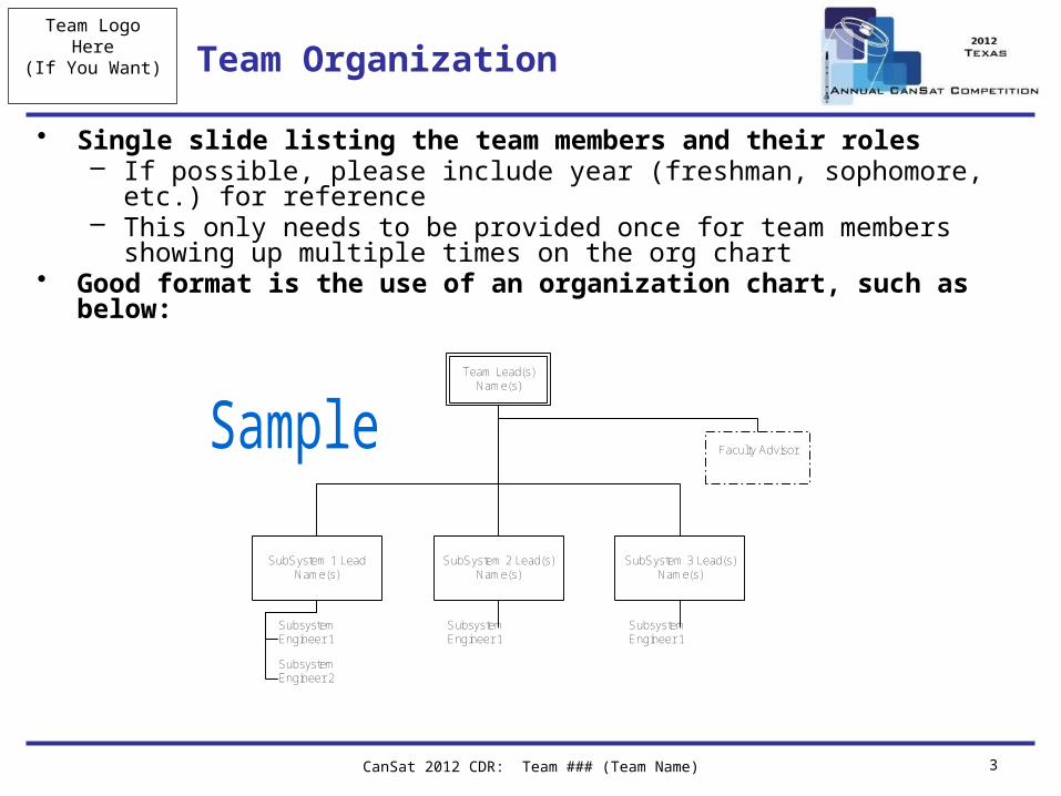
Team Organization
• Single slide listing the team members and their roles– If possible, please include year (freshman, sophomore, etc.) for reference– This only needs to be provided once for team members showing up multiple
times on the org chart• Good format is the use of an organization chart, such as below:
Team Lead(s)Name(s)
SubSystem 2 Lead(s)Name(s)
SubSystem 3 Lead(s)Name(s)
SubSystem 1 LeadName(s)
Faculty Advisor
Subsystem Engineer 1 Subsystem Engineer 2
Subsystem Engineer 1
Subsystem Engineer 1
Team LogoHere
(If You Want)
CanSat 2012 CDR: Team ### (Team Name) 4
Acronyms
• Provide a list of acronyms used throughout the presentation.– DURING PRESENTATIONS – DO NOT READ
THROUGH THESE ACRONYMS
Team LogoHere
CanSat 2012 CDR: Team ### (Team Name) 5
Systems Overview
Presenter Name(s) Go Here
The purpose of this section is to introduce the reviewer to the overall requirements and configuration of the CanSat.This provides a basis for the details presented in thesubsystem sections.
Team LogoHere
(If You Want)
CanSat 2012 CDR: Team ### (Team Name) 6
Mission Summary
• Overview of the mission objectives• Indicate which one (1) selectable objective is being
attempted– Selection rationale?
• Also include any external objectives (personal, laboratory or sponsor, class, etc.) relevant to the design
Team LogoHere
(If You Want) Summary of Changes Since PDR
• Overview design changes since PDR• Details of the changes are discussed in subsequent
sections.
CanSat 2012 CDR: Team ### (Team Name) 7
Team LogoHere
(If You Want)
CanSat 2012 CDR: Team ### (Team Name) 8
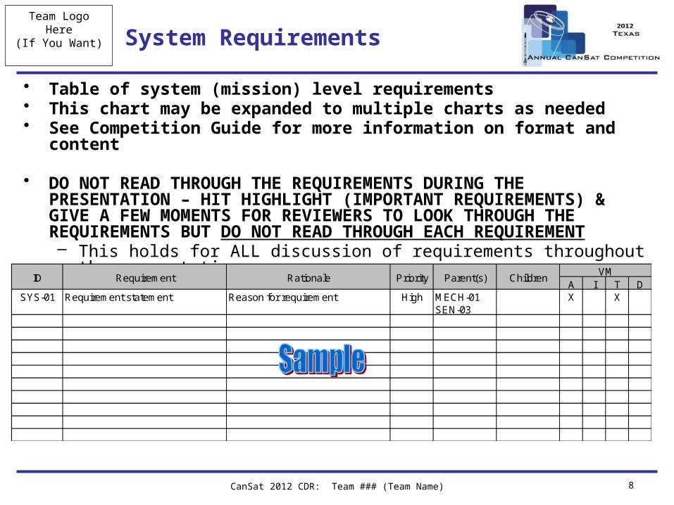
System Requirements
• Table of system (mission) level requirements• This chart may be expanded to multiple charts as needed• See Competition Guide for more information on format and content
• DO NOT READ THROUGH THE REQUIREMENTS DURING THE PRESENTATION – HIT HIGHLIGHT (IMPORTANT REQUIREMENTS) & GIVE A FEW MOMENTS FOR REVIEWERS TO LOOK THROUGH THE REQUIREMENTS BUT DO NOT READ THROUGH EACH REQUIREMENT– This holds for ALL discussion of requirements throughout the presentation
A I T DSYS-01 Requirement statement Reason for requirement High MECH-01
SEN-03X X
RationaleRequirementIDVM
ChildrenParent(s)Priority
Team LogoHere
(If You Want)
CanSat 2012 CDR: Team ### (Team Name) 9
System Concept of Operations
• 1-3 slides (roughly) providing overview of CanSat operations
• Should include– Pre-launch activities– Launch and descent operations– Post-launch recovery and data reduction
• Focus on launch day activities• Team member roles and responsibilities on launch day• Simple flow diagrams and cartoons are a good way to
present the CONOPS
Team LogoHere
(If You Want)
CanSat 2012 CDR: Team ### (Team Name) 10
Physical Layout
• Diagram(s) showing physical layout of selected CanSat configuration
• Make sure to include:– Dimensions– Placement of major components– Relevant configurations
• Carrier, lander, launch configuration, deployed, etc.
• The goal is to present the physical idea of what the CanSat will look like for reference prior to getting into details of the CanSat design
Team LogoHere
(If You Want)
CanSat 2012 CDR: Team ### (Team Name) 11
Launch Vehicle Compatibility
• Discussion of how the CanSats are integrated into the rocket payload section
• Discussion of how the CanSat compatibility will be verified prior to launch day
• Include a dimensioned drawing that shows clearances with the payload section– Focus on launch configuration (carrier + lander)– Include all descent control apparatus– At CDR this should include measured and/or prototype dimensions
• Notes:– In past years there were a large number of CanSats that did not
deploy from the payload sections of the rocket
Team LogoHere
CanSat 2012 CDR: Team ### (Team Name) 12
Sensor Subsystem Design
Presenter Name(s) Go Here
Team LogoHere
(If You Want) Sensor Subsystem Overview
• One slide providing an overview of the CanSat sensor system– Include summary of the selected sensors (type &
models)– Include brief discussion of what the sensors are used for– Focus on selected component (not all components
trades)– Include overview of both carrier and lander sensors, as
applicable
CanSat 2012 CDR: Team ### (Team Name) 13
Team LogoHere
(If You Want)
CanSat 2012 CDR: Team ### (Team Name) 14
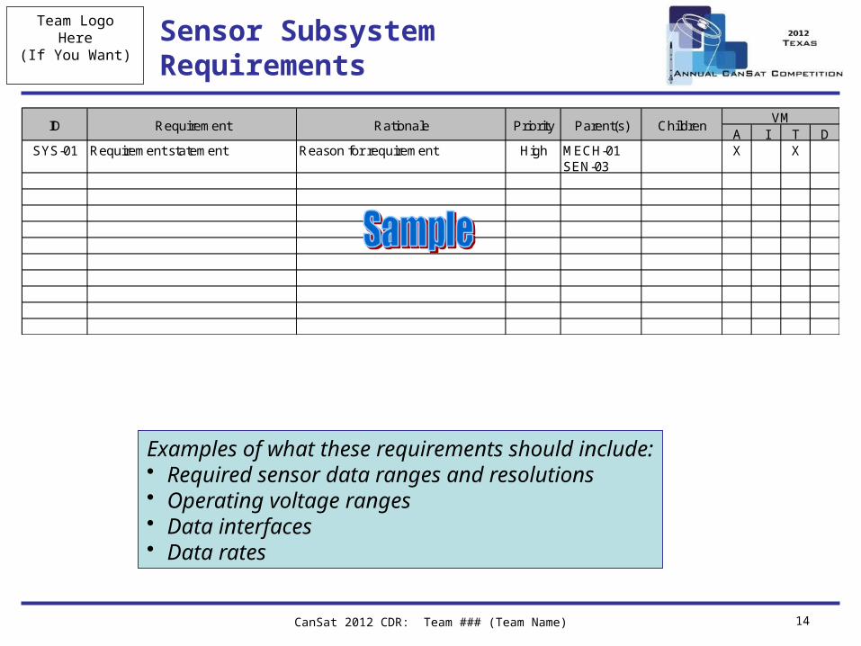
Sensor Subsystem Requirements
A I T DSYS-01 Requirement statement Reason for requirement High MECH-01
SEN-03X X
RationaleRequirementIDVM
ChildrenParent(s)Priority
Examples of what these requirements should include:• Required sensor data ranges and resolutions• Operating voltage ranges• Data interfaces• Data rates
Team LogoHere
(If You Want) Sensor Changes Since PDR
• ONE slide providing an overview of the CanSat sensor system changes since PDR– Include rationale– Include changes to both carrier and lander sensors
CanSat 2012 CDR: Team ### (Team Name) 15
Team LogoHere
(If You Want)
CanSat 2012 CDR: Team ### (Team Name) 16
Carrier GPS Summary
• Summary of GPS sensor selection and characteristics• Include:
– GPS data accuracy and data format– Overview of data processing (including equations, as
appropriate)
Team LogoHere
(If You Want)
CanSat 2012 CDR: Team ### (Team Name) 17
Carrier Non-GPS Altitude Sensor Summary
• Summary of altitude sensor selection and characteristics
• Include:– Sensor accuracy and data format– Overview of data processing (including equations, as
appropriate)
Team LogoHere
(If You Want)
CanSat 2012 CDR: Team ### (Team Name) 18
Carrier Air Temperature Summary
• Summary of air temperature sensor selection and characteristics
• Include:– Sensor accuracy and data format– Overview of data formats (including equations, as
appropriate)
Team LogoHere
(If You Want)
CanSat 2012 CDR: Team ### (Team Name) 19
Lander Altitude Sensor Summary
• Summary of lander altitude sensor selection and characteristics
• Include:– Sensor accuracy and data format– Overview of data formats (including equations, as
appropriate)
Team LogoHere
(If You Want)
CanSat 2012 CDR: Team ### (Team Name) 20
Lander Impact Force Sensor Summary
• SELECTABLE OBJECTIVE – ONLY REQUIRED IF SELECTED
• Summary of sensor selection and characteristics• Include:
– Sensor accuracy and data format– Overview of data processing (including equations, as
appropriate)
Team LogoHere
(If You Want)
CanSat 2012 CDR: Team ### (Team Name) 21
Carrier Camera Summary
• SELECTABLE OBJECTIVE – ONLY REQUIRED IF SELECTED
• Summary of camera selection and characteristics• Include:
– Image resolution– Data formats– How images are handled onboard and reconstructed on
the ground
Team LogoHere
(If You Want)
CanSat 2012 CDR: Team ### (Team Name) 22
Carrier Video Camera Summary
• SELECTABLE OBJECTIVE – ONLY REQUIRED IF SELECTED– Image resolution– Data formats– Frame rate– How images are handled, stored onboard, and
reconstructed on the ground
Presenter: Name goes here
Team LogoHere
(If You Want)
CanSat 2012 CDR: Team ### (Team Name) 23
Lander Video Camera Selection
• SELECTABLE OBJECTIVE – ONLY REQUIRED IF SELECTED– Image resolution– Data formats– Frame rate– How images are handled, stored onboard, and
reconstructed on the ground
Presenter: Name goes here
Team LogoHere
CanSat 2012 CDR: Team ### (Team Name) 24
Descent Control Design
Presenter Name(s) Go Here
Team LogoHere
(If You Want)
CanSat 2012 CDR: Team ### (Team Name) 25
Descent Control Overview
• ONE slide providing an overview of the carrier and lander descent control system
• Include overview of the selected configurations and components necessary
Team LogoHere
(If You Want)
CanSat 2012 CDR: Team ### (Team Name) 26
Descent Control Changes Since PDR
• List changes since the PDR for both Carrier and Lander
Team LogoHere
(If You Want)
CanSat 2012 CDR: Team ### (Team Name) 27
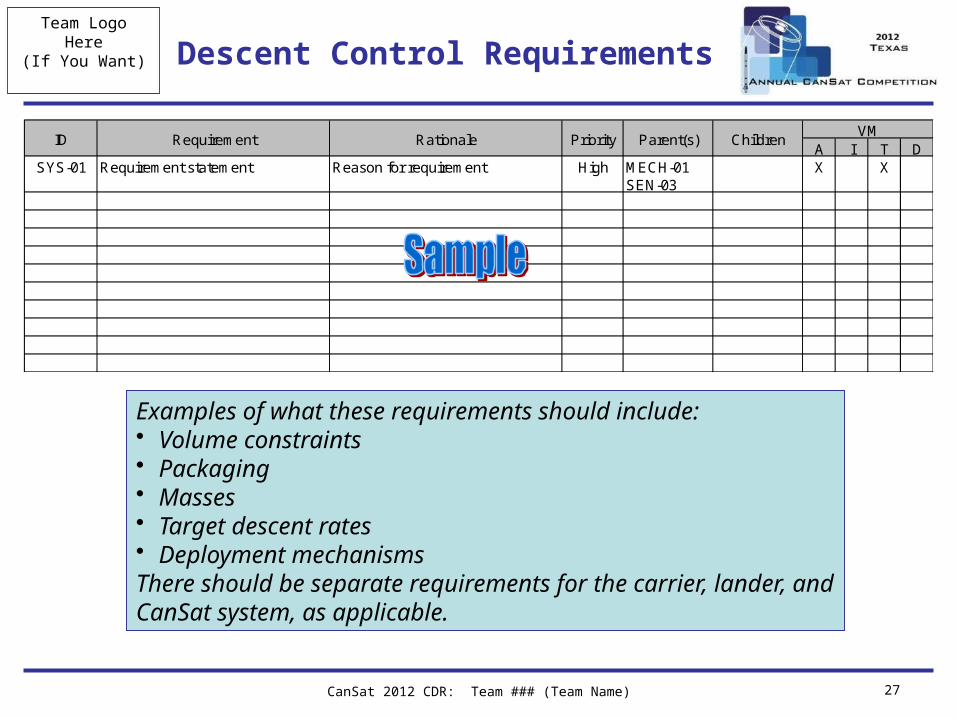
Descent Control Requirements
A I T DSYS-01 Requirement statement Reason for requirement High MECH-01
SEN-03X X
RationaleRequirementIDVM
ChildrenParent(s)Priority
Examples of what these requirements should include:• Volume constraints• Packaging• Masses• Target descent rates• Deployment mechanismsThere should be separate requirements for the carrier, lander, andCanSat system, as applicable.
Team LogoHere
(If You Want)
CanSat 2012 CDR: Team ### (Team Name) 28
Carrier Descent Control Hardware Summary
• Summary of Carrier DCS sensors and actuator selection and characteristics– Shock force survival– Preflight Review testability
• For passive components, discuss:– Component sizing– Key design considerations– Color selection(s)
• For active components, discuss:– Sensor accuracy and data formats– Overview of sensor data processing– Actuator control, command rates, and data formats
Team LogoHere
(If You Want)
CanSat 2012 CDR: Team ### (Team Name) 29
Lander Descent Control Hardware Summary
• Summary of Lander DCS sensors and actuator selection and characteristics– Include deployment trigger and mechanism
• For passive components, discuss:– Component sizing– Key design considerations– Color selection(s)
• For active components, discuss:– Sensor accuracy and data formats– Overview of sensor data processing– Actuator control, command rates, and data formats
Team LogoHere
(If You Want)
CanSat 2012 CDR: Team ### (Team Name) 30
Descent Rate Estimates
• Cover estimates for the following CanSat configurations– Carrier + lander post separation (prior to deployment of
the lander)– Carrier following deployment of the lander– Lander following separation from the carrier
• Include discussion of – Calculations used – Assumptions
• This discussion can carrier over to multiple slides if necessary
Team LogoHere
CanSat 2012 CDR: Team ### (Team Name) 31
Mechanical Subsystem Design
Presenter Name(s) Go Here
Team LogoHere
(If You Want)
CanSat 2012 CDR: Team ### (Team Name) 32
Mechanical Subsystem Overview
• ONE slide providing overview of the mechanical subsystem– Include overview of major structural elements, material
selection, and interface definitions
Team LogoHere
(If You Want)Mechanical Subsystem Changes Since PDR
• Highlight mechanical changes since PDR. Details should be discussed on subsequent slides.
CanSat 2012 CDR: Team ### (Team Name) 33
Team LogoHere
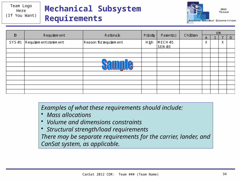
(If You Want)Mechanical Subsystem Requirements
CanSat 2012 CDR: Team ### (Team Name) 34
A I T DSYS-01 Requirement statement Reason for requirement High MECH-01
SEN-03X X
RationaleRequirementIDVM
ChildrenParent(s)Priority
Examples of what these requirements should include:• Mass allocations• Volume and dimensions constraints• Structural strength/load requirementsThere may be separate requirements for the carrier, lander, andCanSat system, as applicable.
Team LogoHere
(If You Want)
CanSat 2012 CDR: Team ### (Team Name) 35
Lander Egg Protection Overview
• Details of how the egg will be protected during flight and landing
Team LogoHere
(If You Want) Mechanical Layout of Components
• Dimensioned diagrams showing:– Major structural elements– Overall dimensions of the CanSat– Component presentation
CanSat 2012 CDR: Team ### (Team Name) 36
Team LogoHere
(If You Want) Material Selections
• Discussion of what materials will be used for the mechanical components and why
CanSat 2012 CDR: Team ### (Team Name) 37
Team LogoHere
(If You Want)
CanSat 2012 CDR: Team ### (Team Name) 38
Carrier-Lander Interface
• Describe how the lander will be connected to and released (mechanically) from the carrier– Needs to include discussion of how descent control
apparatus will be accommodated– Redundancy / failure modes?
Team LogoHere
(If You Want) Structure and Survivability
• For both Carrier and Lander discuss:– Electronic component mounting methods– Electronic component enclosures– Acceleration and shock force requirements and testing
CanSat 2012 CDR: Team ### (Team Name) 39
Team LogoHere
(If You Want)
CanSat 2012 CDR: Team ### (Team Name) 40
Mass Budget
• Table(s) providing the following:– Mass of all components– Mass of all structural elements– Sources/uncertainties – whether the masses are
estimates, from data sheets, measured values, etc.– Total mass– Margins
• Must clearly distinguish between carrier and lander masses– Include allocated mass for egg payload
Team LogoHere
CanSat 2012 CDR: Team ### (Team Name) 41
Communication and Data Handling Subsystem Design
Presenter Name(s) Go Here
Team LogoHere
(If You Want)
CanSat 2012 CDR: Team ### (Team Name) 42
CDH Overview
• ONE slide providing overview of the CDH subsystem– Should include selected components (with brief mention
of what each component is for)
Team LogoHere
(If You Want) CDH Changes Since PDR
• List changes to the CDH since PDR. Details of the changes should be discussed in subsequent slides.
CanSat 2012 CDR: Team ### (Team Name) 43
Team LogoHere
(If You Want)
CanSat 2012 CDR: Team ### (Team Name) 44
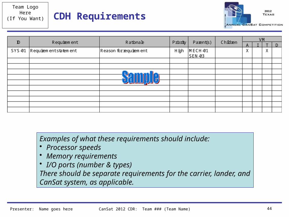
CDH Requirements
Presenter: Name goes here
A I T DSYS-01 Requirement statement Reason for requirement High MECH-01
SEN-03X X
RationaleRequirementIDVM
ChildrenParent(s)Priority
Examples of what these requirements should include:• Processor speeds• Memory requirements• I/O ports (number & types)There should be separate requirements for the carrier, lander, andCanSat system, as applicable.
Team LogoHere
(If You Want)
CanSat 2012 CDR: Team ### (Team Name) 45
Processor & Memory Selection
• Include processor speed• Include data interfaces (types and numbers)• Include memory storage requirements, if applicable• Discussion for both Carrier and Lander• May be more than one slide if necessary
Team LogoHere
(If You Want)
CanSat 2012 CDR: Team ### (Team Name) 46
Carrier Antenna Selection
• Description and characteristics of the antenna selected for the CanSat
• Consider:– Performance– Mass
Team LogoHere
(If You Want) Data Package Definitions
• Demonstrate an understanding of the communications protocols and packets for each component of the Carrier and Lander design– Radio– GPS– Other sensors– Optional sensors (camera / impact force sensor)– Storage device protocols
CanSat 2012 CDR: Team ### (Team Name) 47
Team LogoHere
(If You Want)
CanSat 2012 CDR: Team ### (Team Name) 48
Radio Configuration
• Demonstrate an understanding of the protocol required to initialize and utilize the XBEE radio module
• Provide description of the impact those requirements have on the CanSat design
• Include transmission control– How is this managed during each mission phase?
• Prototype progress and testing results to date• Note:
– Communications failures have occurred often over the past several years of the competition
– You are encouraged to use your radios in all of your development and testing to better ensure mission success
Complete Radio Prototyping and Testing Early!
Team LogoHere
(If You Want)
CanSat 2012 CDR: Team ### (Team Name) 49
Carrier Telemetry Format
• What data is included?• Data rate of packet?• How is data formatted?
– Include example frames with descriptions
Team LogoHere
(If You Want)
CanSat 2012 CDR: Team ### (Team Name) 50
Activation of Telemetry Transmissions
• Discuss how telemetry transmissions are enabled via remote command on the launch pad
Presenter: Name goes here
Team LogoHere
(If You Want)
CanSat 2012 CDR: Team ### (Team Name) 51
Locator Device Selection Overview
• This include locator devices for Carrier and Lander• How are audible locator devices will be activated and
deactivated?– (e.g. how and when the locators are activated and how
they will be deactivated upon recovery)• Include:
– Power consumption– Audible volume– Activation trigger– Switch
• Describe Carrier and Lander are labeled to facilitate return if the CanSat is not recovered on launch day
Team LogoHere
CanSat 2012 CDR: Team ### (Team Name) 52
Electrical Power Subsystem Design
Presenter Name(s) Go Here
Team LogoHere
(If You Want)
CanSat 2012 CDR: Team ### (Team Name) 53
EPS Overview
• ONE slide providing overview of EPS components (with purposes)
• Consider a diagram
Team LogoHere
(If You Want) EPS Changes Since PDR
• List changes to the EPS subsystem since PDR. Details of changes should be discussed in subsequent slides.
CanSat 2012 CDR: Team ### (Team Name) 54
Team LogoHere
(If You Want)
CanSat 2012 CDR: Team ### (Team Name) 55
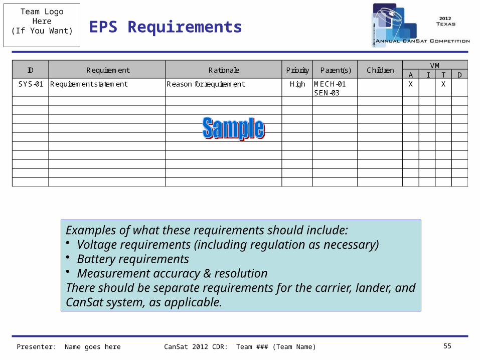
EPS Requirements
Presenter: Name goes here
A I T DSYS-01 Requirement statement Reason for requirement High MECH-01
SEN-03X X
RationaleRequirementIDVM
ChildrenParent(s)Priority
Examples of what these requirements should include:• Voltage requirements (including regulation as necessary)• Battery requirements• Measurement accuracy & resolutionThere should be separate requirements for the carrier, lander, andCanSat system, as applicable.
Team LogoHere
(If You Want)
CanSat 2012 CDR: Team ### (Team Name) 56
Carrier Electrical Block Diagram
• High-level schematic (not down to the resistor level) showing power connections– Include required voltages– Include all major components
• Include details of how power will be controlled and verified externally without disassembling the CanSat (e.g., include power switch and LED in diagram)
Team LogoHere
(If You Want)
CanSat 2012 CDR: Team ### (Team Name) 57
Lander Electrical Block Diagram
• High-level schematic (not down to the resistor level) showing power connections– Include required voltages– Include all major components
• Include details of how power will be controlled and verified externally without disassembling the CanSat (e.g., include power switch and LED in diagram)
Team LogoHere
(If You Want)
CanSat 2012 CDR: Team ### (Team Name) 58
Carrier Power Budget
• Power budget in tabular format which includes:– Power consumption (W) of all components– Expected duty cycles for all components– Source/uncertainty for each line item
• Estimate, data sheet, measurement, etc.
– Total power consumed– Power available– Margins
Team LogoHere
(If You Want)
CanSat 2012 CDR: Team ### (Team Name) 59
Lander Power Budget
• Power budget in tabular format which includes:– Power consumption (W) of all components– Expected duty cycles for all components– Source/uncertainty for each line item
• Estimate, data sheet, measurement, etc.
– Total power consumed– Power available– Battery capacity– Margins
• Including potential one hour wait on the launch pad
Team LogoHere
(If You Want)
CanSat 2012 CDR: Team ### (Team Name) 60
Power Source Summary
• Discussion of power source selection• Include power source selection of Carrier and Lander
Presenter: Name goes here
Team LogoHere
(If You Want)
CanSat 2012 CDR: Team ### (Team Name) 61
Battery Voltage Measurement
• Details of how the battery voltage is measured. • This should include a discussion of the measurement
range and resolution, data conversions, etc.
Team LogoHere
CanSat 2012 CDR: Team ### (Team Name) 62
Flight Software Design
Presenter Name(s) Go Here
Team LogoHere
(If You Want)
CanSat 2012 CDR: Team ### (Team Name) 63
FSW Overview
• 1-2 slides providing overview of the CanSat FSW design• Should discuss
– Basic FSW architecture– Programming languages– Development environments– Brief summary of what the FSW has to do
Team LogoHere
(If You Want) FSW Changes Since PDR
• Overview of the CanSat FSW changes since the PDR. Details of the changes should be discussed in subsequent slides.
CanSat 2012 CDR: Team ### (Team Name) 64
Team LogoHere
(If You Want)
CanSat 2012 CDR: Team ### (Team Name) 65
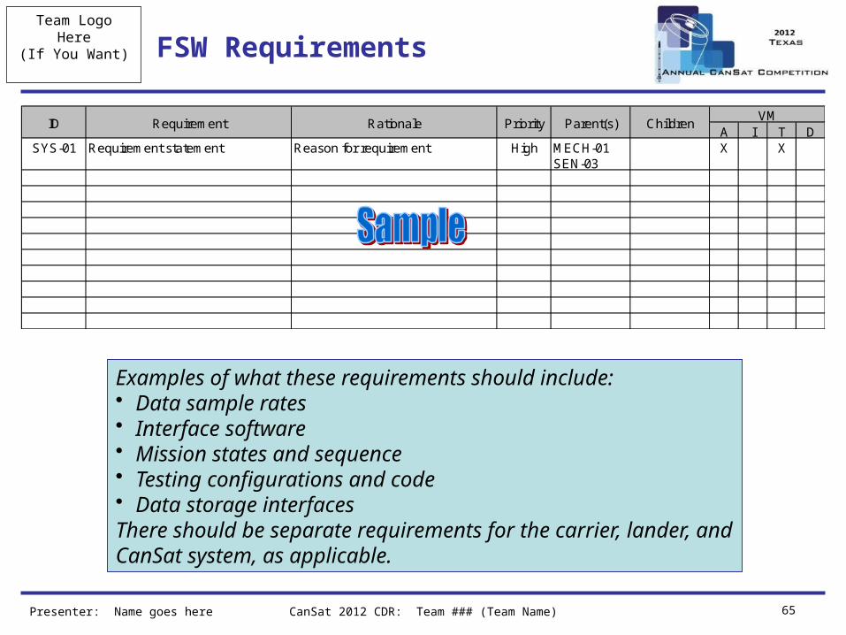
FSW Requirements
Presenter: Name goes here
A I T DSYS-01 Requirement statement Reason for requirement High MECH-01
SEN-03X X
RationaleRequirementIDVM
ChildrenParent(s)Priority
Examples of what these requirements should include:• Data sample rates• Interface software• Mission states and sequence• Testing configurations and code• Data storage interfacesThere should be separate requirements for the carrier, lander, andCanSat system, as applicable.
Team LogoHere
(If You Want)
CanSat 2012 CDR: Team ### (Team Name) 66
Carrier CanSat FSW Overview
• Software flow diagram for carrier CanSat• Things to be included:
– Sampling of sensors (including rates)– Communications– Data storage (if applicable)– Hardware interfaces– Throughput– Libraries used for each sensor / interface
• Discuss timing and throughput calculations• May be 1 – 3 slides• Focus on changes since PDR
Team LogoHere
(If You Want)Carrier Software Flow Diagram or Pseudocode
• Major decision points in the logic
CanSat 2012 CDR: Team ### (Team Name) 67
Team LogoHere
(If You Want)
CanSat 2012 CDR: Team ### (Team Name) 68
Lander CanSat FSW Overview
• Software flow diagram for carrier CanSat• Things to be included:
– Sampling of sensors (including rates)– Communications– Data storage (if applicable)– Hardware interfaces– Throughput– Libraries used for each sensor / interface
• Discuss timing and throughput calculations• May be 1 – 3 slides
Team LogoHere
(If You Want)Lander Flow Diagram or Psuedocode
• Major decision points in the logic
CanSat 2012 CDR: Team ### (Team Name) 69
Team LogoHere
(If You Want)
CanSat 2012 CDR: Team ### (Team Name) 70
Software Development Plan
• A common CanSat problem is late software development
• Present a slide describing the plan for software development and plans to reduce the risk of late software development
• Include:– Prototyping and prototyping environments– Software subsystem development sequence– Development team– Test methodology
• Discuss progress since PDR
Presenter: Name goes here
Team LogoHere
CanSat 2012 CDR: Team ### (Team Name) 71
Ground Control System Design
Presenter Name(s) Go Here
Team LogoHere
(If You Want)
CanSat 2012 CDR: Team ### (Team Name) 72
GCS Overview
• Include a simple context diagram showing major components (computers, antenna, adaptors, etc.)
Team LogoHere
(If You Want)
CanSat 2012 CDR: Team ### (Team Name) 73
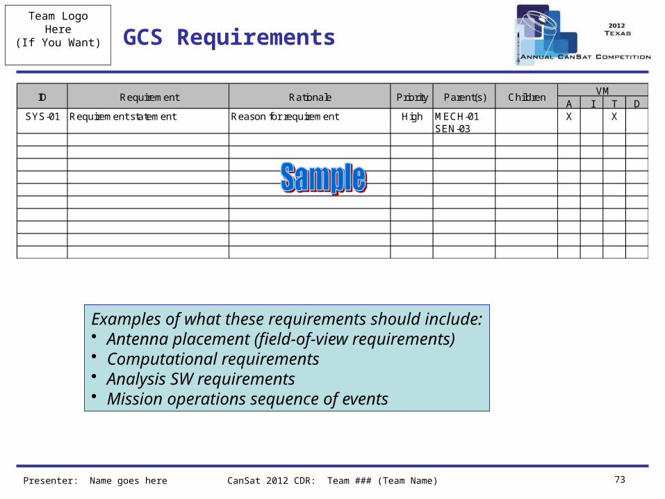
GCS Requirements
Presenter: Name goes here
A I T DSYS-01 Requirement statement Reason for requirement High MECH-01
SEN-03X X
RationaleRequirementIDVM
ChildrenParent(s)Priority
Examples of what these requirements should include:• Antenna placement (field-of-view requirements)• Computational requirements• Analysis SW requirements• Mission operations sequence of events
Team LogoHere
(If You Want)
CanSat 2012 CDR: Team ### (Team Name) 74
GCS Antenna Selection
• Discussion of the selection of the GCS antenna• Include:
– Antenna placement and coverage• Diagram is recommended
– Antenna height and mounting strategy• Launch day construction
– Distance link predictions and margins– Screen shot of ground control software in operation
Team LogoHere
(If You Want) GCS Software
• Telemetry display screen shots• Commercial off the shelf (COTS) software packages
used• Real-time plotting software design• Data archiving and retrieval approach• Command software and interface• Progress since PDR• Testing
CanSat 2012 CDR: Team ### (Team Name) 75
Team LogoHere
CanSat 2012 CDR: Team ### (Team Name) 76
CanSat Integration and Test
Presenter Name(s) Go Here
Team LogoHere
(If You Want)
CanSat 2012 PDR: Team ### (Team Name) 77
CanSat Integration and Test Overview
• 3-5 slides• Discussion of how the CanSat subsystems will be integrated• Discussion of system-level tests to be performed on the integrated
CanSat• At PDR this should include concepts for how subsystems will be
integrated– Sequence (which subsystems are needed prior to others)– Test equipment necessary– Test environments necessary
• The goal(s) at CDR are– Convey integration plans– Convey plans of how the CanSat is tested as a unit
Presenter: Name goes here
Team LogoHere
(If You Want)Sensor Subsystem Testing Overview
• Discuss tests being performed in order to verify the sensor subsystem.
• The test selection should demonstrate an understanding of what is important for testing each sensor at the subsystem and system levels.
• It is not necessary to go through each test in detail, but provide:– What each test is to accomplish?– Constraints on testing (necessary operational subsystems, ground
support equipment, etc.)– Pass/fail criteria and expected results – what are you looking for?
(not just “it works” – discuss how you know it works)
CanSat 2012 CDR: Team ### (Team Name) 78
Team LogoHere
(If You Want)
CanSat 2012 CDR: Team ### (Team Name) 79
Lander Impact Force Sensor Testing
• SELECTABLE OBJECTIVE – ONLY REQUIRED IF SELECTED
• Overview of impact force sensor testing and results, including pass/fail criteria, etc.
Team LogoHere
(If You Want)
CanSat 2012 CDR: Team ### (Team Name) 80
Imaging / Video Camera Testing Overview
• SELECTABLE OBJECTIVE – ONLY REQUIRED IF SELECTED
• May include only one of the following (based on optional selections):– Carrier still camera, carrier video camera, or lander video
camera testing• Include:
– Overview of camera testing and results, including pass/fail criteria, etc.
– Include sample pictures, triggering mechanism, and diagrams of camera location and test setup
– Test through put results– Image recovery
Team LogoHere
(If You Want) DCS Subsystem Testing Overview
• Discuss tests being performed in order to verify the DCS
• Demonstrate an understanding of what is important for testing each components at the subsystem and system levels
• It is not necessary to go through each test in detail, but provide:– What each test is to accomplish?– Constraints on testing (necessary operational subsystems, ground
support equipment, etc.)– Pass/fail criteria and expected results – what are you looking for?
(not just “it works” – discuss how you know it works)– Drop testing / simulation
CanSat 2012 CDR: Team ### (Team Name) 81
Team LogoHere
(If You Want)Mechanical Subsystem Testing Overview
• Discuss tests being performed in order to verify the Mechanical Subsystem.
• Demonstrate an understanding of what is important for mechanical testing at the subsystem and system levels. What each test is to accomplish?– Constraints on testing (necessary operational
subsystems, ground support equipment, etc.)– Pass/fail criteria and expected results – what are you
looking for? (not just “it works” – discuss how you know it works)
– Deployment / separation testing– Acceleration / shock / survivability requirement testing
CanSat 2012 CDR: Team ### (Team Name) 82
Team LogoHere
(If You Want) CDH Subsystem Testing Overview
• Discuss tests being performed in order to verify the CDH Subsystem
• Demonstrate an understanding of what is important for testing each component at the subsystem and system levels
• It is not necessary to go through each test in detail, but provide:– What each test is to accomplish?– Constraints on testing (necessary operational subsystems, ground
support equipment, etc.)– Pass/fail criteria and expected results – what are you looking for?
(not just “it works” – discuss how you know it works)– Simulation test beds / ground system checkout tests
CanSat 2012 CDR: Team ### (Team Name) 83
Team LogoHere
(If You Want) EPS Testing Overview
• Discuss the test being performed to verify the EPS• Demonstrate an understanding of what is important for
testing each component at the subsystem and system levels
• It is not necessary to go through each test in detail, but provide:– What each test is to accomplish?– Constraints on testing (necessary operational subsystems, ground
support equipment, etc.)– Voltage sensor testing– Pass/fail criteria and expected results – what are you looking for?
(not just “it works” – discuss how you know it works)
CanSat 2012 CDR: Team ### (Team Name) 84
Team LogoHere
(If You Want) FSW Testing Overview
• Discuss tests being performed in order to verify the flight software
• Test selection should demonstrate an understanding of what is important for software at subsystem and system levels
• It is not necessary to go through each test in detail, but provide:– What each test is to accomplish?– Constraints on testing (necessary operational subsystems, ground
support equipment, etc.)– Pass/fail criteria and expected results – what are you looking for?
(not just “it works” – discuss how you know it works)– Simulation test beds / ground system checkout tests
CanSat 2012 CDR: Team ### (Team Name) 85
Team LogoHere
(If You Want) GCS Testing Overview
• Discuss tests being performed in order to verify the GCS.
• Demonstrate an understanding of what is important for testing each sensor at the subsystem and system levels
• It is not necessary to go through each test in detail, but provide:– What each test is to accomplish?– Constraints on testing (necessary operational subsystems, ground
support equipment, etc.)– Pass/fail criteria and expected results – what are you looking for?
(not just “it works” – discuss how you know it works)– Simulation test beds / ground system checkout tests
CanSat 2012 CDR: Team ### (Team Name) 86
Team LogoHere
CanSat 2012 CDR: Team ### (Team Name) 87
Mission Operations & Analysis
Presenter Name(s) Go Here
Team LogoHere
(If You Want)
CanSat 2012 CDR: Team ### (Team Name) 88
Overview of Mission Sequence of Events
• Launch-day sequence of events– Should start with arrival at the launch site and proceed
through recovery and data analysis• Include”
– Flow chart of events– Team member roles and responsibilities– Antenna construction and ground system setup– CanSat assembly and test
Presenter: Name goes here
Team LogoHere
(If You Want)
CanSat 2012 PDR: Team ### (Team Name) 89
Field Safety Rules Compliance
• Discuss development and content of the Missions Operations Manual for your CanSat
• Discuss development status
Presenter: Name goes here
Team LogoHere
(If You Want)
CanSat 2012 CDR: Team ### (Team Name) 90
CanSat Location and Recovery
• Discuss how you will find your CanSats in the field– Discuss Carrier and Lander recovery
Presenter: Name goes here
Team LogoHere
(If You Want) Mission Rehearsal Activities
• Description of mission operations rehearsal activities including:– Details of activities rehearsed to date
• Ground system radio link check procedures• Loading the egg payload• Powering on/off the CanSat• Launch configuration preparations (e.g., final assembly and
stowing appendages)• Loading the CanSat in the launch vehicle• Telemetry processing, archiving, and analysis• Recovery
• Description of written procedures developed/required
CanSat 2012 CDR: Team ### (Team Name) 91
Team LogoHere
CanSat 2012 CDR: Team ### (Team Name) 92
Management
Presenter Name(s) Go Here
Team LogoHere
(If You Want)
CanSat 2012 CDR: Team ### (Team Name) 93
Status of Procurements
• Provide status of sensor and component procurements– What has been ordered, when it arrives, etc.– This should include flight and GCS hardware (and
software if being ordered)• This information should be reflected in the overall
schedule
Presenter: Name goes here
Team LogoHere
(If You Want)
CanSat 2012 CDR: Team ### (Team Name) 94
CanSat Budget – Hardware
• Provide a table listing the costs of the CanSat flight hardware
• Table should include– Cost of major components and hardware– Indication of whether these costs are actual, estimates,
or budgeted values– Indication of hardware re-use from previous years
• The current market value for re-used components should be included
Team LogoHere
(If You Want)
CanSat 2012 CDR: Team ### (Team Name) 95
CanSat Budget – Other Costs
• Table(s) (same format as Hardware Budget) showing– Ground control station costs– Other costs
• Prototyping• Test facilities and equipment• Rentals• Computers• Travel
– Income• Sources of project income
• The goal(s) of this budget are– To provide an understanding of the overall design and development costs– Get the teams thinking about the overall costs including necessary funds for
travel– Identify shortfalls in the budget that require attention
• In the past some teams have not been able to attend the competition due to a lack of funds
• If caught early enough, there are a number of resources for funding that may available to teams
– THE COMPEITION DOES NOT PROVIDE ANY DEVELOPMENT FUNDING OR DONORS
Team LogoHere
(If You Want)
CanSat 2012 CDR: Team ### (Team Name) 96
Program Schedule
• Overview of development schedule to include– Competition milestones– Academic milestones and holidays– Major development activities– Component/hardware deliveries– Major integration and test activities and milestones
• The schedule should be “wrapped up” to 1-2 levels– Show high-level tasks only in order to make the schedule readable– It is recommended a schedule at lower levels is developed in order to provide the
team with tools for tracking progress and assessing trouble areas• The goals of this schedule are to
– Provide a tool for the team to track progress of CanSat design and development– Provide tool for judges to assess trouble areas and offer ways for the team to best
meet the objectives of the competition• A Gantt chart showing task start and stop dates and durations is recommended
– Schedule should include linkages between tasks to provide the team with an idea of what happens in the overall flow when milestones are not met on time
• Make sure the schedule is readable in the presentation– This may require the schedule to be broken between multiple slides
• Failure to do so will result in a loss of points
Team LogoHere
(If You Want) Conclusions
• Presentation summary and conclusions• In general include the following:
– Major accomplishments– Major unfinished work– Testing to complete– Flight software status
CanSat 2012 CDR: Team ### (Team Name) 97
Team LogoHere
CanSat 2012 CDR: Team ### (Team Name) 98
Presentation Scoring & Additional Information
The following slides provide additional information regarding presentation scoring, as well as
recommendations for the presentations and slides
Team LogoHere
(If You Want)
CanSat 2012 CDR: Team ### (Team Name) 99
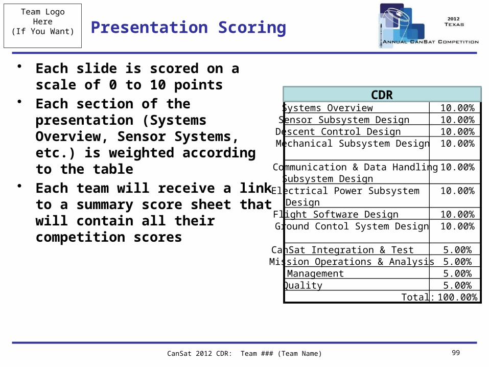
Presentation Scoring
• Each slide is scored on a scale of 0 to 10 points
• Each section of the presentation (Systems Overview, Sensor Systems, etc.) is weighted according to the table
• Each team will receive a link to a summary score sheet that will contain all their competition scores
Systems Overview 10.00%Sensor Subsystem Design 10.00%Descent Control Design 10.00%Mechanical Subsystem Design 10.00%
Communication & Data Handling Subsystem Design
10.00%
Electrical Power Subsystem Design
10.00%
Flight Software Design 10.00%Ground Contol System Design 10.00%
CanSat Integration & Test 5.00%Mission Operations & Analysis 5.00%Management 5.00%Quality 5.00%
Total: 100.00%
PDRCDR
Team LogoHere
(If You Want)
CanSat 2012 CDR: Team ### (Team Name) 100
PPT Template Use
• All teams shall use this presentation template• Team logos
– A team logo can be inserted into the placeholder location (and size) on the master slide
– If no logo is to be used, remove the placeholder from the master slide
• Team numbers in the footer should be updated in the footer information view– REMEMBER TO PUT YOUR TEAM NUMBER IN THE FOOTER– Team names are optional – if no team name is used, please delete
from footer text• On each slide, replace the “Name goes here” in the bottom left corner
with the name of the person(s) presenting that slide– This will allow the judges to know the person to address any
questions or comments to
Team LogoHere
(If You Want)Template Update Log (Do not include in presentation)
• 0.1 Initial version• 0.2
– Page 51, removed mistaken requirement for telemetry transmission termination
• 0.3 – Added stars ( ) to indicate which charts must be covered in the
presentation. Other slides will be reviewed by judges off-line.– Deleted chart 38 (redundant carrier-lander interface)
• 0.4– Corrected slide 22, 24 to be summary rather than trade study
CanSat 2012 CDR: Team ### (Team Name) 101