Embed Size (px)
Citation preview
Our policy is one of continued research and development. We therefore reserve the right to amend, without notice, the specifications given in this document. (2020-9331a) © 2015 IMI International s.r.o.
02/21en 8.200.611.01
Technical features
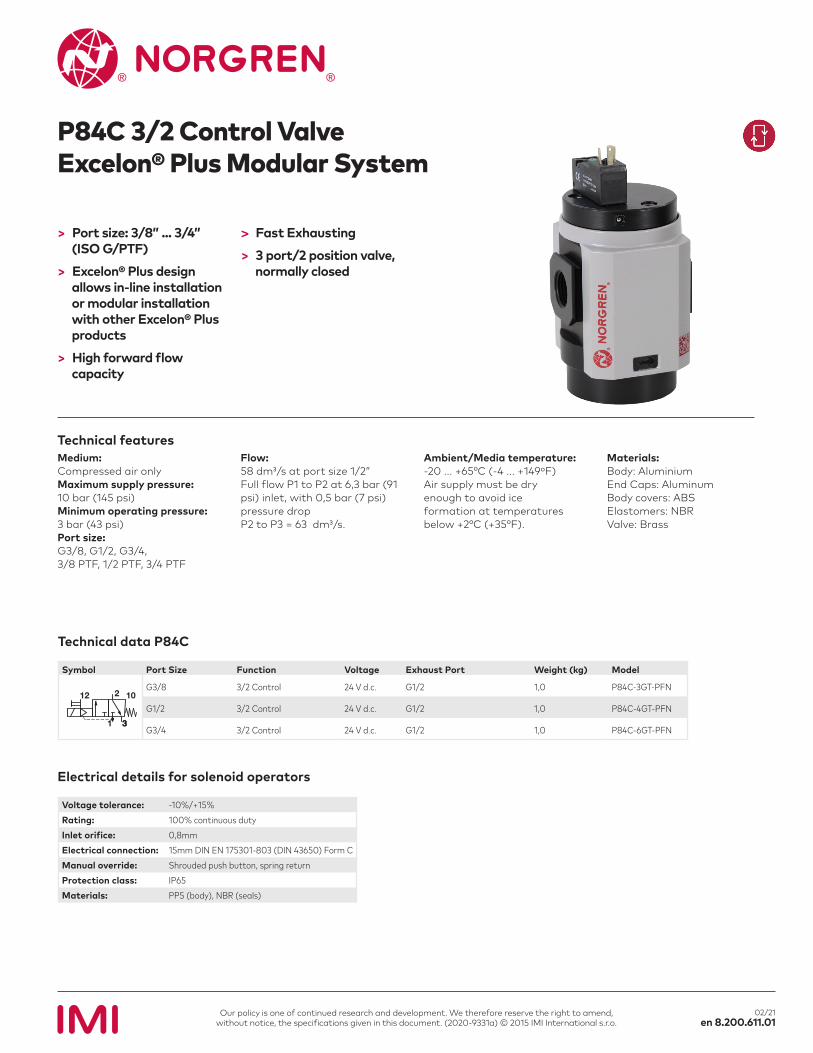
P84C 3/2 Control ValveExcelon® Plus Modular System
> Port size: 3/8” ... 3/4” (ISO G/PTF)
> Excelon® Plus design allows in-line installation or modular installation with other Excelon® Plus products
> High forward flow capacity
> Fast Exhausting
> 3 port/2 position valve, normally closed
Medium:Compressed air onlyMaximum supply pressure:10 bar (145 psi)Minimum operating pressure:3 bar (43 psi)Port size:G3/8, G1/2, G3/4,3/8 PTF, 1/2 PTF, 3/4 PTF
Flow:58 dm3/s at port size 1/2”Full flow P1 to P2 at 6,3 bar (91 psi) inlet, with 0,5 bar (7 psi) pressure dropP2 to P3 = 63 dm3/s.
Ambient/Media temperature:-20 ... +65°C (-4 ... +149ºF)Air supply must be dry enough to avoid ice formation at temperatures below +2°C (+35°F).
Materials:Body: AluminiumEnd Caps: AluminumBody covers: ABSElastomers: NBRValve: Brass
Technical data P84C
Symbol Port Size Function Voltage Exhaust Port Weight (kg) Model
1012
3
2
1 3
G3/8 3/2 Control 24 V d.c. G1/2 1,0 P84C-3GT-PFN
G1/2 3/2 Control 24 V d.c. G1/2 1,0 P84C-4GT-PFN
G3/4 3/2 Control 24 V d.c. G1/2 1,0 P84C-6GT-PFN
Voltage tolerance: -10%/+15%Rating: 100% continuous dutyInlet orifice: 0,8mmElectrical connection: 15mm DIN EN 175301-803 (DIN 43650) Form CManual override: Shrouded push button, spring returnProtection class: IP65Materials: PP5 (body), NBR (seals)
Electrical details for solenoid operators
Pre
ssur
e dr
op Δ
p (b
ar)
Pre
ssur
e dr
op Δ
p (b
ar)
Air flow (dm3/s)
Air flow (dm3/s)
0
0
10
10
60
60
20
20
70
70
30
30
80
80
40
40
90
90
50
50
100
100
Port size: 3/8”
Port size: 1/2”
1,0
0,8
0,6
0,4
0,2
0
1,0
0,8
0,6
0,4
0,2
0
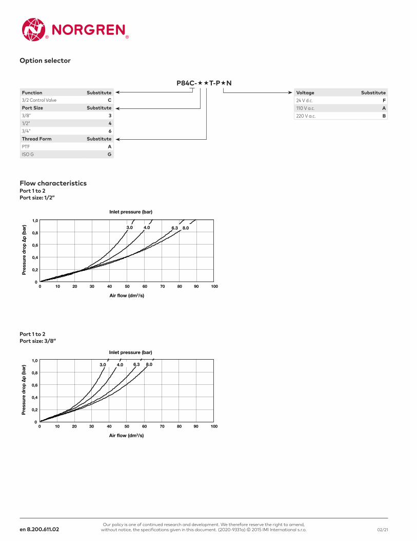
3.0 4.0 8.06.3
3.0 4.0 8.06.3
Inlet pressure (bar)
Inlet pressure (bar)
Our policy is one of continued research and development. We therefore reserve the right to amend, without notice, the specifications given in this document. (2020-9331a) © 2015 IMI International s.r.o.en 8.200.611.02 02/21
Flow characteristics
P84C-T-PN
Option selector
Function Substitute3/2 Control Valve CPort Size Substitute3/8” 31/2” 43/4” 6Thread Form SubstitutePTF AISO G G
Voltage Substitute24 V d.c. F110 V a.c. A220 V a.c. B
Port 1 to 2Port size: 1/2”
Port 1 to 2Port size: 3/8”
Our policy is one of continued research and development. We therefore reserve the right to amend, without notice, the specifications given in this document. (2020-9331a) © 2015 IMI International s.r.o. en 8.200.611.0302/21
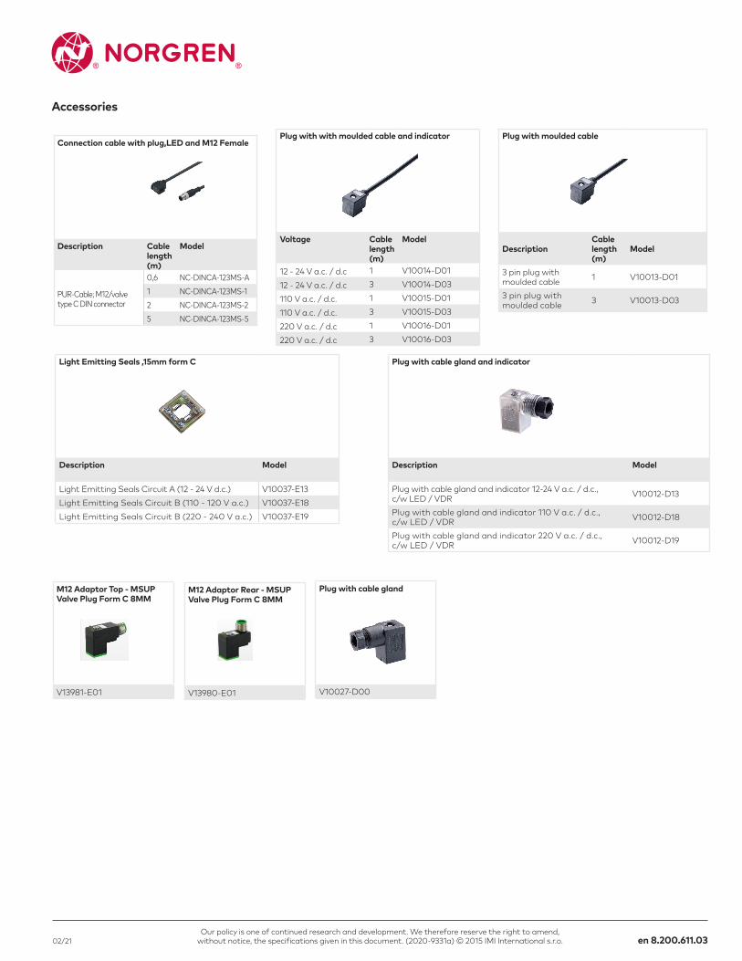
Light Emitting Seals ,15mm form C
Description Model
Light Emitting Seals Circuit A (12 - 24 V d.c.) V10037-E13 Light Emitting Seals Circuit B (110 - 120 V a.c.) V10037-E18Light Emitting Seals Circuit B (220 - 240 V a.c.) V10037-E19
Plug with with moulded cable and indicator
Voltage Cable length (m)
Model
12 - 24 V a.c. / d.c 1 V10014-D01
12 - 24 V a.c. / d.c 3 V10014-D03
110 V a.c. / d.c. 1 V10015-D01
110 V a.c. / d.c. 3 V10015-D03
220 V a.c. / d.c 1 V10016-D01
220 V a.c. / d.c 3 V10016-D03
Plug with moulded cable
DescriptionCable length (m)
Model
3 pin plug with moulded cable 1 V10013-D01
3 pin plug with moulded cable 3 V10013-D03
Plug with cable gland and indicator
Description Model
Plug with cable gland and indicator 12-24 V a.c. / d.c., c/w LED / VDR V10012-D13
Plug with cable gland and indicator 110 V a.c. / d.c., c/w LED / VDR V10012-D18
Plug with cable gland and indicator 220 V a.c. / d.c., c/w LED / VDR V10012-D19
M12 Adaptor Top - MSUP Valve Plug Form C 8MM
V13981-E01
M12 Adaptor Rear - MSUP Valve Plug Form C 8MM
V13980-E01
Plug with cable gland
V10027-D00
Accessories
Connection cable with plug,LED and M12 Female
Description Cable length (m)
Model
PUR-Cable; M12/valve type C DIN connector
0,6 NC-DINCA-123MS-A1 NC-DINCA-123MS-12 NC-DINCA-123MS-25 NC-DINCA-123MS-5
Our policy is one of continued research and development. We therefore reserve the right to amend, without notice, the specifications given in this document. (2020-9331a) © 2015 IMI International s.r.o.en 8.200.611.04 02/21
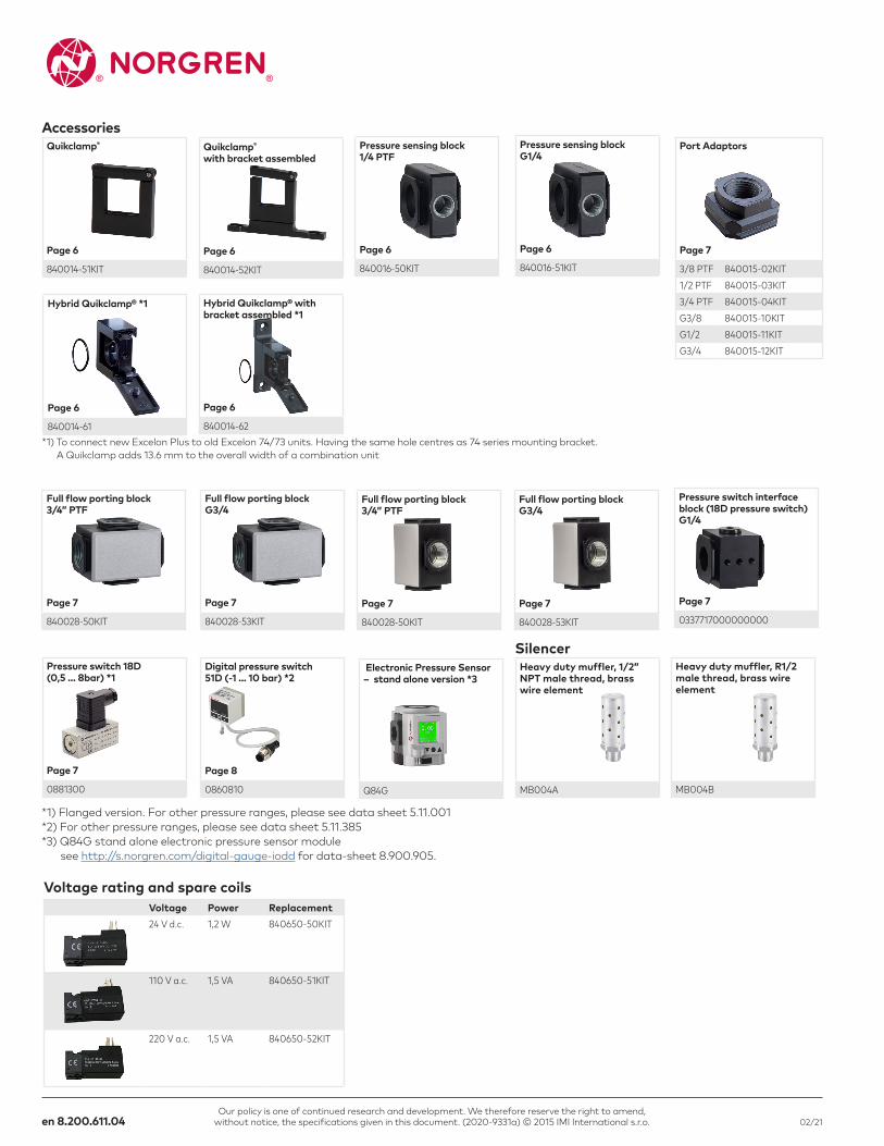
Accessories Quikclamp®
Page 6
840014-51KIT
Quikclamp®
with bracket assembled
Page 6
840014-52KIT
Pressure sensing block 1/4 PTF
Page 6
840016-50KIT
Pressure sensing block G1/4
Page 6
840016-51KIT
Port Adaptors
Page 7
3/8 PTF 840015-02KIT1/2 PTF 840015-03KIT3/4 PTF 840015-04KITG3/8 840015-10KITG1/2 840015-11KITG3/4 840015-12KIT
Hybrid Quikclamp® *1
Page 6
840014-61
Hybrid Quikclamp® with bracket assembled *1
Page 6
840014-62
Full flow porting block 3/4” PTF
Page 7
840028-50KIT
Full flow porting block G3/4
Page 7
840028-53KIT
Full flow porting block 3/4” PTF
Page 7
840028-50KIT
Full flow porting block G3/4
Page 7
840028-53KIT
*1) To connect new Excelon Plus to old Excelon 74/73 units. Having the same hole centres as 74 series mounting bracket. A Quikclamp adds 13.6 mm to the overall width of a combination unit
Pressure switch interface block (18D pressure switch) G1/4
Page 7
0337717000000000
Electronic Pressure Sensor – stand alone version *3
Q84G
Pressure switch 18D (0,5 ... 8bar) *1
Page 7
0881300
Digital pressure switch 51D (-1 ... 10 bar) *2
Page 8
0860810
*1) Flanged version. For other pressure ranges, please see data sheet 5.11.001 *2) For other pressure ranges, please see data sheet 5.11.385 *3) Q84G stand alone electronic pressure sensor module see http://s.norgren.com/digital-gauge-iodd for data-sheet 8.900.905.
SilencerHeavy duty muffler, 1/2” NPT male thread, brass wire element
MB004A
Heavy duty muffler, R1/2 male thread, brass wire element
MB004B
Voltage rating and spare coilsVoltage Power Replacement24 V d.c. 1,2 W 840650-50KIT
110 V a.c. 1,5 VA 840650-51KIT
220 V a.c. 1,5 VA 840650-52KIT
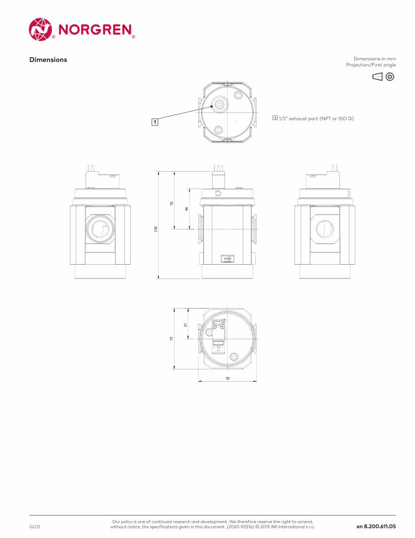
70
73
37
70
130
49
1
Our policy is one of continued research and development. We therefore reserve the right to amend, without notice, the specifications given in this document. (2020-9331a) © 2015 IMI International s.r.o. en 8.200.611.0502/21
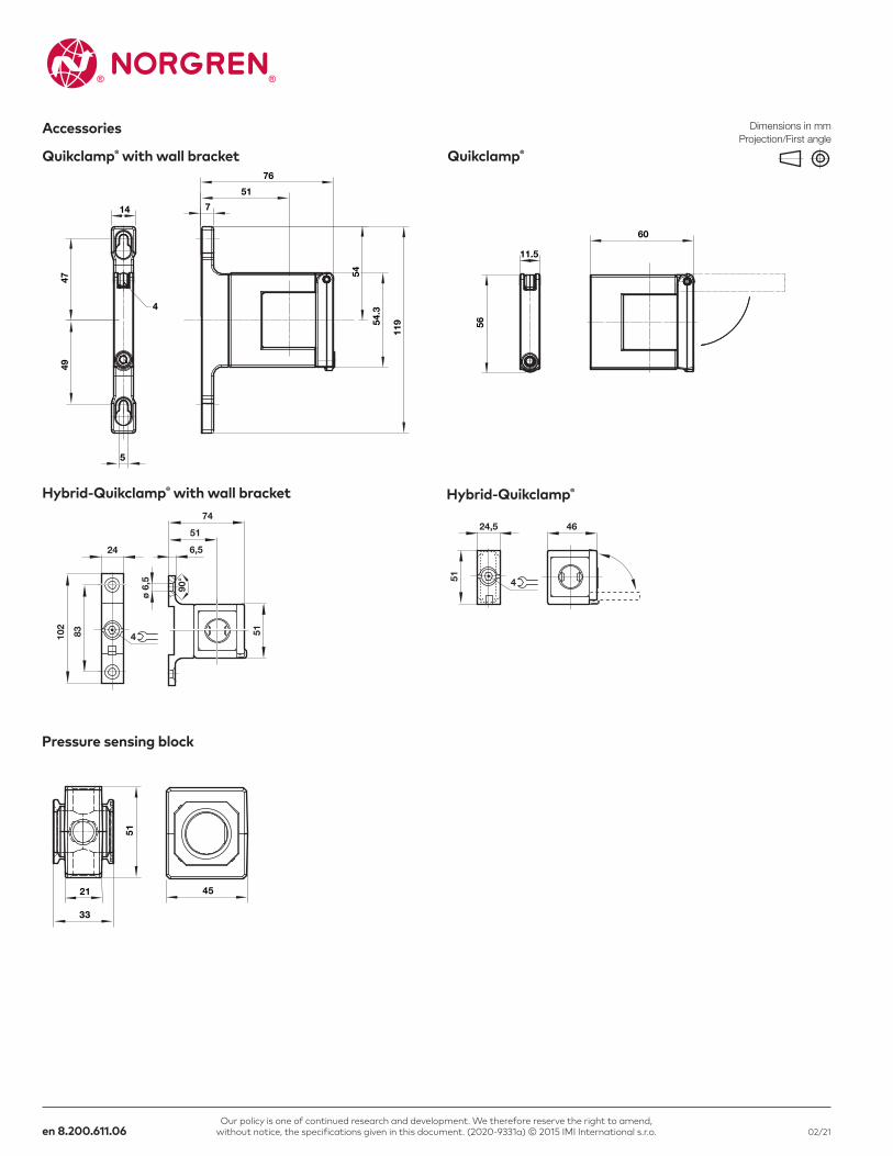
Dimensions Dimensions in mm Projection/First angle
1 1/2” exhaust port (NPT or ISO G)
56
11.5
60
4749
76
119
54
14
4
5
7
51
54.3
51
21
33
45
51
24,5 46
4
102
83
24
51
6,5
74
90°
ø 6
,5
514
Our policy is one of continued research and development. We therefore reserve the right to amend, without notice, the specifications given in this document. (2020-9331a) © 2015 IMI International s.r.o.en 8.200.611.06 02/21
Dimensions in mm Projection/First angle
Accessories
Quikclamp®Quikclamp® with wall bracket
Pressure sensing block
Hybrid-Quikclamp® with wall bracket Hybrid-Quikclamp®
44
32
40
40G1/2
30
30
28
5
45
18 A
/C
35
72
38.5
38.5
18
80 51
5746
68
80
51
57
46
68
32
44
40
57
40
G 1/4
29
29
G 1/8
37
300
˷
31
31
31
1
2
3
4
6 57
16
Our policy is one of continued research and development. We therefore reserve the right to amend, without notice, the specifications given in this document. (2020-9331a) © 2015 IMI International s.r.o. en 8.200.611.0702/21
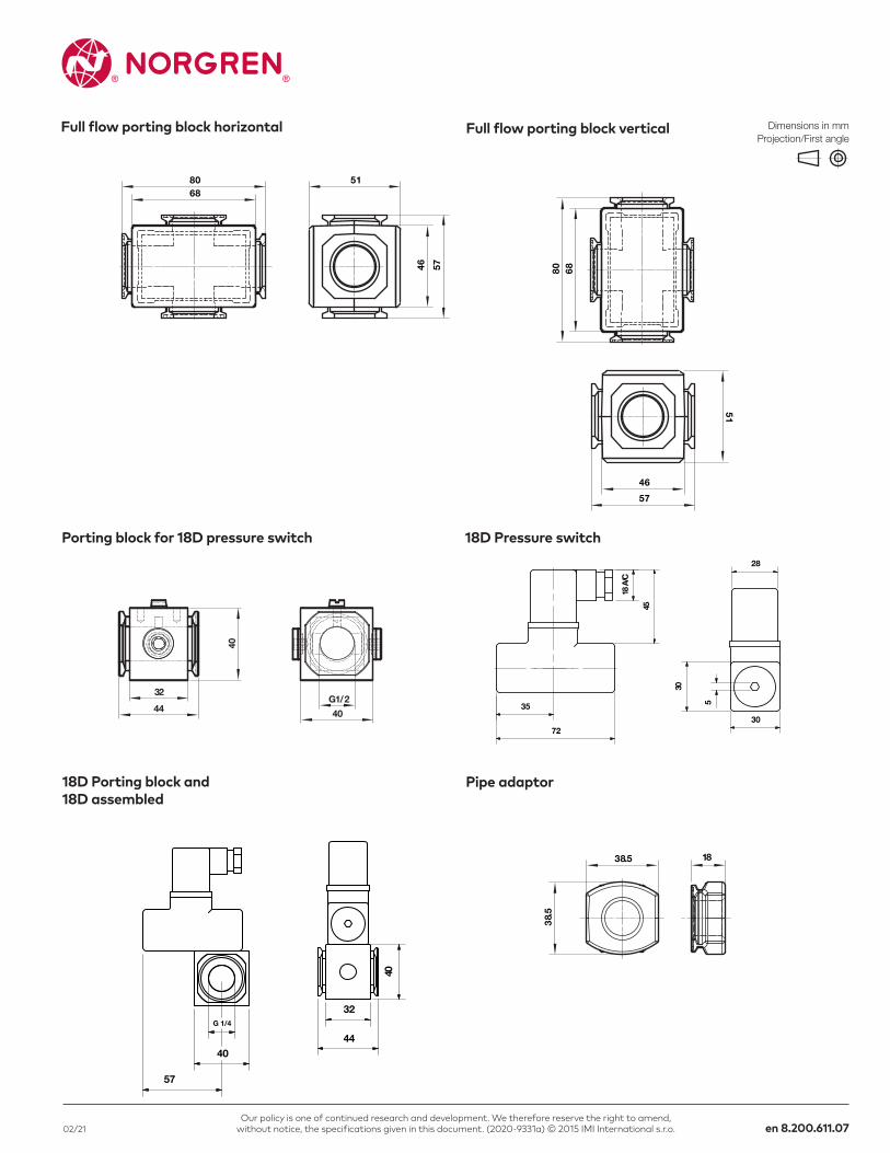
18D Pressure switchPorting block for 18D pressure switch
18D Porting block and 18D assembled
Pipe adaptor
Dimensions in mm Projection/First angle
Full flow porting block horizontal Full flow porting block vertical
~300
311
3
56
4
7
31
G1/
8
36,5
~30
2
C
Ø D
B
A
Our policy is one of continued research and development. We therefore reserve the right to amend, without notice, the specifications given in this document. (2020-9331a) © 2015 IMI International s.r.o.en 8.200.611.08 02/21
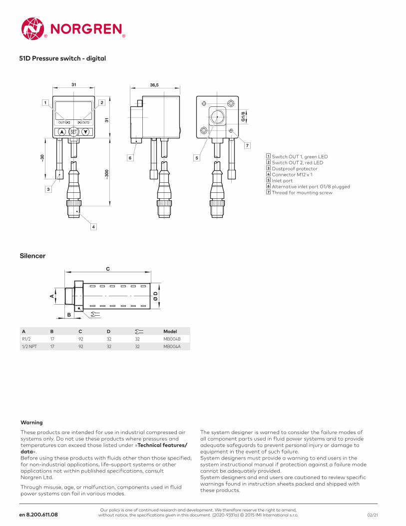
51D Pressure switch - digital
1 Switch OUT 1, green LED 2 Switch OUT 2, red LED 3 Dustproof protector 4 Connector M12 x 1 5 Inlet port 6 Alternative inlet port G1/8 plugged 7 Thread for mounting screw
Warning
These products are intended for use in industrial compressed air systems only. Do not use these products where pressures and temperatures can exceed those listed under »Technical features/data«. Before using these products with fluids other than those specified, for non-industrial applications, life-support systems or other applications not within published specifications, consult Norgren Ltd.
Through misuse, age, or malfunction, components used in fluid power systems can fail in various modes.
The system designer is warned to consider the failure modes of all component parts used in fluid power systems and to provide adequate safeguards to prevent personal injury or damage to equipment in the event of such failure. System designers must provide a warning to end users in the system instructional manual if protection against a failure mode cannot be adequately provided. System designers and end users are cautioned to review specific warnings found in instruction sheets packed and shipped with these products.
EN - Englisch
Silencer
A B C D ModelR1/2 17 92 32 32 MB004B1/2 NPT 17 92 32 32 MB004A