Embed Size (px)
Citation preview

Pain in the Neck: Post Operative Appearance of the Cervical Spine
Wong P1, Uriell M1, Presciutti S2, Robertson D1, Umpierrez M1, Carpenter W1, Singer A1
1Department of Radiology and Imaging SciencesDivision of Musculoskeletal Imaging
2Department of Orthopedic Surgery
Emory University

Disclosure
The authors have no proprietary or commercial interest in any of the materials discussed in this exhibit.

Learning Objectives
1. Review cervical spine anatomy and terminology on different imaging modalities.
2. Review common indications for cervical spine surgery in the non-traumatic setting.
3. Discuss and illustrate imaging features of common cervical spine surgical techniques and hardware in the non-traumatic setting.
4. Recognize examples of postoperative complications and their imaging appearance.

Cervical Spine Radiographic Anatomy
Vertebral Body
UncinateProcess
SpinousProcess
Transverse Process
Pedicle
Atlantoccipitaljoint
Atlas
Dens
Lamina
Airway
Prevertebral soft tissue
SpinousProcess
Superior facet
Inferior facet

Cervical Spine CT Anatomy
Vertebral body
Spinous process
C2 Dens
Intervertebral surface
Intervertebral disc
Spinal canal
Anterior tubercle
Foramen transversarium
Transverse process
Lateral mass
Posterior tubercle
Anterior tubercle
Posteriortubercle
Foramen transversarium
Transverse process
Pedicle
Lamina
C1 anterior arch
C1 posterior arch
C1 anterior arch
C1 posterior arch
C4 vertebral body

Cervical Spine MR Anatomy
Anterior Longitudinal
ligament
Posterior Longitudinal ligament
Tectorial Membrane
Intervertebral disc
Interspinousligament
Spinal Cord
Ligamentum flavum
Nuchal Ligament
Vertebral body
Anterior atlantoccipital
membrane
CSF space
Neural foramenRight vertebral artery flow void
Facet Posterior lamina

Common Indications for Cervical Spine Surgery in the Non-traumatic Setting
Degenerative Cervical Spondylosis Disc Herniation Congenital Stenosis

Common Indications for Cervical Spine Surgery in the Non-traumatic Setting
Ossification of the posterior longitudinal ligament
Tumor Infection
Cervical Kyphosis

Cervical Spinal Surgical Techniques and Hardware
• Anterior Cervical Discectomy and Fusion (ACDF)
• Total Disc Replacement
• Laminectomy and Posterior Fusion
• Laminoplasty
• Posterior Cervical Foraminotomy
*The authors acknowledge that additional cervical spinal surgical techniques exist, however will not be discussed in this presentation.

Anterior vs. Posterior Approach
• Sagittal alignment (Degree of kyphosis)
• Number of disease segments
• Stenosis morphology (anterior versus posterior compression)
• Clinical symptoms– Axial neck pain
– Dysphagia
– Dysphonia
– Medical comorbidities that may inhibit fusion

Anterior Cervical Discectomy and Fusion (ACDF)
• Mainstay of treatment with single or two level disease
• Cervical myelopathy with fixed cervical kyphosis > 10 degrees
• Anterior pathology (Ossification of the posterior longitudinal ligament, disc osteophyte complexes, herniated discs)
• Avoid in patients with symptoms such as dysphagia, dysphonia
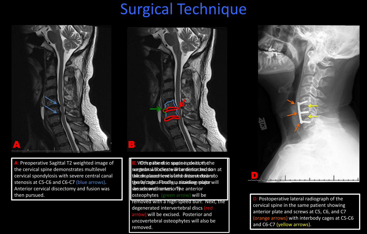
Surgical Technique
A: Preoperative Sagittal T2 weighted image of the cervical spine demonstrates multilevel cervical spondylosis with severe central canal stenosis at C5-C6 and C6-C7 (blue arrows). Anterior cervical discectomy and fusion was then pursued.
B: With patient in supine position, the surgeon will create an anterior incision at the diseased levels and dissect down to the vertebral bodies, avoiding major vessels and nerves. The anterior osteophytes (green arrow) will be removed with a high-speed burr. Next, the degenerated intervertebral discs (red arrow) will be excised. Posterior and uncovertebral osteophytes will also be removed.
C: Once the disc space is clear, the vertebral bodies will be distracted to allow placement of the intervertebral graft/cage. Finally, a titanium plate will be screwed anteriorly.
D: Postoperative lateral radiograph of the cervical spine in the same patient showing anterior plate and screws at C5, C6, and C7 (orange arrows) with interbody cages at C5-C6 and C6-C7 (yellow arrows).
A CB
D

84 year old male with progressive upper and lower extremity weakness 12/2014 12/2014 12/2015
Teaching Point: Anterior cervical discectomy and fusion (ACDF) is the mainstay of treatment in patients with cervical radiculopathy and and up to 3-4 levels of cervical myelopathy. In addition, anterior surgery is preferred in the setting of kyphosis.1
A and B: Lateral radiograph (A) and Sagittal T2 w/fat saturation (B) images of the cervical spine demonstrating multilevel disc degeneration and facet arthropathy with critical spinal canal stenosis at C3-C4 and abnormal T2 cord signal (blue arrow) at that level.
C and D: Immediate post-op lateral radiograph (C) demonstrating interval anterior cervical diskectomy and placement of intervertebral cage for fusion with anterior plate and screws at C3-C4 (green arrows). Coned-in view of the hardware reveals the radiolucent intervertebral cage (red arrow) with radiopaque markers to help determine positioning. The intervertebral cage can either be composed of allograft bone or composed of polyetheretherketone (PEEK) impacted with either autologous or allograft bone. PEEK is a polymer with elasticity similar to cortical bone. (D) 1 year follow up radiograph with evidence of osseous fusion and incorporation of the intervertebral bone graft.
A B C D
1J Am Acad Orthop Surg 2015;23:648-660

Total Disc Replacement
• Typically used in single level disease
• Allows for preservation of motion, thus theoretically reducing risk of adjacent level degeneration.
• Similar outcomes being reported when comparing to fusion surgeries, however further trials are necessary to evaluate.
• Contraindications:
– Symptoms attributed to more than one vertebral level
– Cervical instability (flexion/extension)
– Axial neck pain
– Severe spondylosis with bridging osteophytes at the affected level that can reduce motion
– Anatomic deformity (particularly in patients with ankylosis spondylitis, rheumatoid arthritis)

C
Surgical Technique
A: Preoperative Sagittal T2 image of the cervical spine, which demonstrates a disc extrusion at the level of C6-C7, which resulted in effacement of the spinal cord at that level (blue arrow). Patient’s symptoms corresponded to the level of the disc extrusion. Given the single-level disease, a total disc replacement was pursued.
B: The surgical approach is similar to ACDF with the patient supine and incision is made anteriorly at the diseased level. Any bone spurs will be removed followed by the intervertebral disc elements. Once the intervertebral disc space is clear of disc fragments and bony spurs, the disc arthoplasty will be placed (C).
D: Postoperative lateral radiograph of the cervical spine in the same patient which demonstrates the disc arthroplasty at C6-C7. Fusion is not required with total disc arthroplasty.
A B D

31 year old male with neck pain.
A and B: Sagittal T2 w/fat sat (A) and axial T2 weighted (B) images of the cervical spine demonstrating large left paracentral disc extrusion (blue arrows) at the level of C5-C6 resulting in central canal and severe left neural foraminal stenosis.
C and D: AP (C) and Lateral (D) radiographs of the cervical spine demonstrating artificial disc replacement at C5-C6 with the Bryan™ disc (Medtronic). The Bryan™ disc consists of two titanium alloy shells with anterior stops (green arrow) and a poluyurethane radiolucent nucleus (red arrow).
Teaching Point: Cervical total disc replacement (TDR) is an alternative treatment to fusion in single-level discogenic disease and allows for preservation of motion, which theoretically decreases the risk of adjacent segment degeneration.1
D
B
A
C
1American Journal of Roentgenology. 2014;203: 394-405.

Laminectomy and Posterior Fusion
• Traditionally, the preferred treatment in multisegment disease (greater than 2 segments) including congenital stenosis
• Multilevel compression with less than 10 degrees of kyphosis
• Posterior pathology (hypertrophy or ossification of ligamentumflavum, facet osteophytes)
• Cervical myelopathy in patients with dysphagia, dysphonia
• Contraindicated in kyphosis > 10 degrees
• Laminectomy alone (without fusion) is avoided due to potential for post-laminectomy kyphosis

D and E: Post operative sagittal and axial CT images demonstrating laminectomy (blue arrows) with the bilateral lateral mass screws (red arrows) and adjacent bone graft (green arrows).
E
D
B
C: After removal of the posterior elements, lateral mass screws are placed and angled in order to avoid important structures such as the vertebral arteries in the foramen transversarium (blue arrows). Lateral mass screws may be interconnected with rods. Finally, bone graft material is placed along the posterior elements to allow for fusion (green).
B: With the patient in prone position, the bilateral lamina and spinous processes are exposed at the diseased levels. The bilateral lamina and spinousprocesses are then removed (green arrow).
A: Sagittal T2 image of the cervical spine demonstrating extensive multilevel cervical spondylosis resulting in multiple levels of severe central canal stenosis.
A
Surgical Technique
C

54 year old female with upper extremity weakness.
A: Sagittal T2 weighted MRI of the cervical spine demonstrating severe multilevel cervical spondylosis with critical spinal canal stenosis (blue arrows) at C3-C4, C4-C5, and C5-C6 with increased T2 cord signal and myelomalacia(yellow arrow).
B and C: AP and lateral radiographs of the cervical spine after laminectomy and fusion. Lateral mass screws (green arrows) with interlocking rods (orange arrow) and a horizontal bar at C5 (red arrow). Notice the absence of the spinous processes on the AP and lateral images.
D: Post operative axial CT images of the cervical spine demonstrating appropriate placement of the lateral mass screws (green arrows) which are angled to avoid the foramen transversarium.
E: Axial CT image shows the bone graft material adjacent to the hardware (yellow arrows).
Bone graft material may be harvested from the patient (autograft), typically from the iliac crest, to provide fusion. Alternative, bone graft may be harvested from cadaver tissue (allograft).
A B C
D E

Laminoplasty
• Laminoplasty allows for decompression of multilevel stenotic myelopathy without compromising stability and motion.
• Alternative to avoid post-laminectomy kyphosis
• Motion preserving technique (pseudoarthrosis also not a concern)
• Contraindicated in patients with cervical kyphosis, cervical segment instability, and axial neck pain

Surgical TechniqueOpen Door Technique French Door Technique
A: Axial CT image of the cervical spine. Using a posterior approach, the surgeon creates bilateral troughs at the junction of the lamina and lateral masses, however one side will be incomplete, allowing it to act as a hinge when the contralateral side is open. In this case, the trough was complete on the right (dashed line) and incomplete on the left (yellow dash). The right side is then swung open (like a door) to decompress the canal.
B: A metallic plate is secured over the opening (blue arrow). Yellow arrow demonstrating the incomplete trough.
C: Axial CT image of the cervical spine in a different patient. Again, a posterior approach is used. In the French door technique, bilateral incomplete troughs (yellow dash line) are made at the junction of the lamina and lateral masses. The spinous process (red dashed line) is instead split midline and opened.
D: A metallic plate is secured between the opened split spinous process (red arrow). Yellow arrows demonstrating the bilateral incomplete troughs.
A
B
C
D

70 year old male with neck pain and difficulty walking
A: Lateral radiograph of the cervical spine demonstrating multilevel degenerative changes characterized by intervertebral disc height loss, anterior osteophytes and uncoverterbralhypertrophy.
B and C: Immediate AP (B) and lateral (C) post-op images demonstrating post-surgical changes of C3-C6 laminoplasty with right sided plates and screws (blue arrows).
D and E: Pre (D) and Post (E) operative axial CT images of the cervical spine demonstrating the open door laminoplasty technique. Bilateral troughs have been made at the junction of the laminae and lateral masses. In this case, the trough on the right is complete and on the left it is incomplete (red arrow), which allows it to act as a hinge when the right side is opened. This achieves decompression of the spinal canal. A metallic plate is then secured (green arrow) over the opening.
Teaching Point: Laminoplasty allows for decompression of multiple levels without compromising stability and motion. Laminoplasty is contraindicated in the presence of cervical kyphosis and can worsen axial neck pain.1
B
EDCA
1J Am Acad Orthop Surg 2015;23:648-660

Posterior Cervical Foraminotomy
• Provides decompression of the nerve root while maintaining cervical mobility
• Typically performed for 1 or 2-level unilateral upper extremity radiculopathy due to posterolateral or foraminal disc herniation and/or disc osteophyte complex
• Can also be used in situations with persistent or recurrent radiculopathy after previous ACDF
• Contraindicated in patients with cervical instability, diffuse/multilevel spondylosis, and bilateral radicular symptoms.
• Additional contraindications in patient’s with prior ipsilateral foraminotomy and lateral mass hypoplasia.

Surgical Technique
3D Volume rendered image of the cervical spine from the posterior view. There are large, bulky osteophytes of the left C2-C3 and C3-C4 facet joints (blue arrows).
With the patient placed in prone position, the diseased segments are exposed. A high-speed burr is used to remove the inferior aspect of the cephalad lamina and superior aspect of the inferior lamina as well as the medial aspect of the facet (circles), This can be described as “key-hole” foraminotomy. Care must be taken to preserve at least 50% of the facet joint to maintain stability.
Once the nerve root is identified, it can be decompressed using Kerrisonrongeurs and curettes. Posterolateraldisc fragments can also be removed, if identified, allowing further decompression.

47 year old female with neck and left arm pain.
A, B, and C: Axial (A) and Sagittal (B) CT images as well as 3D Volume rendering (C) of the cervical spine demonstrating severe facet arthropathy resulting in left neural foraminal stenosis (blue arrows).
D, E, and F: Post operative axial (D) and sagittal (E) CT as well as 3D volume rendering (F) of the cervical spine at the same levels demonstrating surgical changes of posterior cervical foraminotomy with widening of the neural foramen (green arrows) and improvement in patient’s symptoms.
7/2015 2/2016
Teaching Point: Typically performed for 1 to 2 segment unilateral radiculopathy. At least 50% of the facet joint should be preserved to avoid instability.
A
C E
D
B F

Post Operative Complications
A: Sagittal CT image of the cervical spine status post posterior laminectomy and fusion.B: Sagittal CT image several months lateral reveals interval posterior migration of the superior most screw with slight posterior angulation of the interlocking rod.
Hardware Migration Hardware Loosening
Hardware Fracture
C and D: Sagittal and coronal CT images of the cervical spine status post posterior laminectomy and fusion with lateral mass screws. Increased lucency is seen around multiple lateral mass screws suggestive of hardware loosening.
E and F: Sagittal CT images of the cervical spine status post ACDF demonstrating fracture of the bilateral superior anterior screws (blue arrows).
12/2010 8/2011
A B
C D
E F

Post Operative Complications
A and B: Sagittal T2 weighted MRI (A) and sagittal CT (B) images of the cervical spine in this patient who is status post posterior laminectom) without fusion. Note the reversal of the normal cervical lordosis (orange line). Post-laminectomy kyphosis is a well-known complication of laminectomy.
Post Laminectomy Kyphosis Screw Malposition
Hematoma
C and D: Axial CT images of the cervical spine in two different patients demonstrating lateral mass screws extending into the foramen transversarium (red arrows), which could result in injury of the vertebral artery.
E: Immediate post ACDF lateral radiograph of the cervical spine demonstrating increased prevertebralsoft tissue thickness suggestive of hematoma (red arrows). F: Repeat lateral radiograph two weeks later demonstrating resolution of the prevertebral soft tissue fullness.
A B
C D
E F

Post Operative Complications
A and B: Axial (A) and sagittal (B) CT images of the cervical spine status post ACDF from C4-T1. There is osteolysis (blue arrows) within the incorporated bone graft and vertebral bodies, a complication seen with the use of bone morphongenic protein (BMP), a growth factor which can be used in the interbody cages to help promote fusion. Other complications of BMPs include dysphagia, respiratory distress, heterotopic ossification, soft tissue swelling, and hematoma formation.
C and D: Degenerative changes with disc height loss and osteophytosis seen in the levels above and below the fused segments (green arrows).
BMP Osteolysis Adjacent level disease
Pseudoarthrosis
E and F: Radiographic and CT findings of pseudoarthrosiswith lucency between the interbody cages and vertebral bodies (red arrows) and increased sclerosis of the vertebral bodies (orange arrows).
A BC D
E F

References
• Carragee E.J., Hurwitz E.L., and Weiner B.K. A critical review of recombinant human bone morphogenetic protein-2 trials in spinal surgery: emerging safety concerns and lessons learned. Spine J. 2011. 11: p. 471-491.
• Dodwad S.J., Dodwad S.N., Prasarn M.L., et al. Posterior Cervical Foraminotomy: Indications, Technique, and Outcomes. Clin Spine Surg. 2016. 29: p. 177-185.
• Emery S.E. Anterior approaches for cervical spondylotic myelopathy: which? When? How? Eur Spine J. 2015. 24 Suppl 2: p. 150-159.• Fehlings M.G., Smith J.S., Kopjar B., et al. Perioperative and delayed complications associated with the surgical treatment of cervical spondylotic
myelopathy based on 302 patients from the AOSpine North America Cervical Spondylotic Myelopathy Study. J Neurosurg Spine. 2012. 16: p. 425-432.
• Geck M.J. and Eismont F.J. Surgical options for the treatment of cervical spondylotic myelopathy. Orthop Clin North Am. 2002. 33: p. 329-348. • Hayashi D., Roemer F.W., Mian A., et al. Imaging features of postoperative complications after spinal surgery and instrumentation. AJR Am J
Roentgenol. 2012. 199: p. W123-129. • Kaminsky S.B., Clark C.R., and Traynelis V.C. Operative treatment of cervical spondylotic myelopathy and radiculopathy. A comparison of
laminectomy and laminoplasty at five year average follow-up. Iowa Orthop J. 2004. 24: p. 95-105. • Kato S. and Fehlings M. Degenerative cervical myelopathy. Curr Rev Musculoskelet Med. 2016. 9: p. 263-271. • Lebl D.R. and Bono C.M. Update on the Diagnosis and Management of Cervical Spondylotic Myelopathy. J Am Acad Orthop Surg. 2015. 23: p.
648-660.• Lebl D.R., Hughes A., Cammisa F.P., Jr., et al. Cervical spondylotic myelopathy: pathophysiology, clinical presentation, and treatment. Hss j. 2011.
7: p. 170-178. • Mummaneni P.V., Kaiser M.G., Matz P.G., et al. Cervical surgical techniques for the treatment of cervical spondylotic myelopathy. J Neurosurg
Spine. 2009. 11: p. 130-141. • Nouh M.R. Spinal fusion-hardware construct: Basic concepts and imaging review. World J Radiol. 2012. 4: p. 193-207. • Patel C.K., Cunningham B.J., and Herkowitz H.N. Techniques in cervical laminoplasty. Spine J. 2002. 2: p. 450-455. • Sun Y., Li L., Zhao J., et al. Comparison between anterior approaches and posterior approaches for the treatment of multilevel cervical
spondylotic myelopathy: A meta-analysis. Clin Neurol Neurosurg. 2015. 134: p. 28-36. • Wang M.Y. and Green B.A. Open-door cervical expansile laminoplasty. Neurosurgery. 2004. 54: p. 119-123; discussion 123-114. • Young P.M., Berquist T.H., Bancroft L.W., et al. Complications of spinal instrumentation. Radiographics. 2007. 27: p. 775-789.