Embed Size (px)
Citation preview

2nd International Topical Meeting on HIGH TEMPERATURE REACTOR TECHNOLOGY Beijing,China,September22-24,2004 #Paper A04
-- 1 --
PBMR PROJECT STATUS AND THE WAY AHEAD
Dieter Matzner PBMR (Pty) Ltd, 2nd Floor Lake Buena Vista Building, Gordon Hood Avenue, Centurion 1267;
PO Box 9396, Centurion 0046, South Africa; [email protected]
ABSTRACT: Description of the evolution of the design up to the current basic design baseline stage. This description highlights the changes made since inception, gives the reasons for making the changes, and describes the latest design configuration in relative detail.
An overview is also given of the effort involved in securing the necessary support from the RSA government, the National Nuclear Regulator, and the current as well as possible future investors. A brief overview is also included of the negotiations and interactions, as a potential bidder in the Next Generation Nuclear Plant - Hydrogen Co-Generation INEEL project with the review groups in the US.
The paper also provides an overview of the next phases in the design and eventual delivery of the demonstration power plant, and the anticipated activities should the bid for the INEEL project be successful. In conclusion, an overview is presented of the anticipated future technology growth path for this type of reactor design.
KEYWORDS: PBMR project status, PBMR design changes, basic design baseline
0. INTRODUCTION Gas-cooled reactors have had a long and varied history dating back to the very early days of the development of nuclear energy. The development proceeded along an evolutionary path together with significant advances in supporting technologies, and in South Africa has culminated in the design of the Pebble Bed Modular Reactor (PBMR). The PBMR is expected to achieve the goals of safe, efficient, environmentally acceptable and economic production of energy at high temperature for the generation of electricity and industrial process heat applications. The PBMR power conversion is based on a single loop direct Brayton thermodynamic cycle with a helium-cooled and graphite-moderated nuclear core assembly as a heat source. The coolant gas transfers heat from the core directly to the power conversion system consisting of gas turbo-machinery, a generator, gas coolers and heat exchangers. An initial design with a power of 268 MWt was produced, and a costing exercise on this plant indicated a too high overnight construction cost. The cost target necessitated the design team to completely revisit the entire plant design. Three major areas were worked on simultaneously: - Power levels were optimized without compromising safety or design margins and staying within
well-known design and manufacturing technologies. - A multi-module design development was completed in order to be able to more accurately
estimate the cost savings resulting from shared plant in a power station. - Value engineering per subsystem was performed to revisit possible improvements,
simplifications and faster construction time schedules. In the following section, the initial 268 MWt design, which served as the reference design in the cost optimization investigations, is described. The subsequent sections provide more detail of the results and work that was done to optimize the power output.

PBMR PROJECT STATUS AND THE WAY AHEAD #A04
-- 2 --
1. THE CONCEPTUAL REFERENCE DESIGN 1.1. Background
The initial conceptual design of the reactor was for a core power of 200 MWt, which was the chosen power level for the German HTR-Modul reactor designed by the HTR GmbH consortium. The HTR-Modul had a core diameter of 3 m with a core height of 9.4 m, and a steam generating secondary cycle. The PBMR chose a direct-cycle gas turbine plant with higher core outlet temperatures than the HTR-Modul plant. The core geometry of the HTR-Modul would allow a power level of only 170 MWt when coupled directly to a gas turbine power generating system as described above. In order to increase the thermal power output of the reactor, the core volume had to be increased. Without increasing the core height and power density, it implied that the diameter of the core had to be increased.
It was also a design objective that the control elements would only be installed in the reflector. To ensure sufficient reactivity coupling with the active core, an increase in the diameter of the core to 3.5 m necessitated the use of the so-called reflector noses. These noses were protrusions of the reflector into the active core with the control elements operating in borings close to the front part of the noses as per the German AVR design [1]. This concept permitted an increase in power to 220 MWt. A number of technical reasons terminated any further work on this concept.
In February 1998 it was decided that an annular core geometry would be pursued. With the irradiation damage characteristics of graphite reflector material still not well understood by the PBMR designers, it was decided that a fixed central reflector structure would not be considered as an option. A core geometry consisting of a central reflector with a nominal diameter of 1.75 m of graphite spheres moving as part of the core was chosen. The core outer diameter was fixed at 3.5 m and the effective core height was set at 9 m. This design yielded a power level of 268 MWt with an electrical power output into the grid of 110 MWe. In the following section, a technical description is provided of this design with emphasis on the technical detail of those Structures, Systems and Components (SSC) that played a role in the cost optimization exercise.
1.2. Technical Description of the 268 MWt Reference Design
1.2.1. The reactor unit The reactor unit is defined as the reactor pressure vessel core internals, consisting of the core barrel, the graphite structures and the reactivity control units. In the 268 MWt reference design, the reactor pressure vessel was approximately 6.2 m in diameter, approximately 20.5 m high, and manufactured from reactor grade forged steel with a wall thickness varying between 120 mm and 220 mm. It had an internal steel core barrel with an internal diameter of 5.8 m and a wall thickness of 50 mm. This internal core barrel in turn supported the graphite reflector and carbon thermal shield. The combined radial thickness of the graphite and carbon was 1 m. The graphite reflector had 35 vertical borings to house the reactivity control units. The volume inside the graphite reflector – the core cavity – had a diameter of 3.5 m and an effective height of 8.5 m. The core consisted of fuel in the form of 60 mm diameter fuel spheres, and a central reflector column of graphite spheres. The graphite spheres had the same diameter as the fuel spheres. The nominal diameter of this dynamic central reflector was 1.75 m. FIGURE 1 shows the reactor unit of the 268 MWt reference design.

HTR2004 Beijing, CHINA, 2004. 9.
-- 3 --
Reserve Shutdown System
Fuel Loading PipesGraphite Loading Pipe
Annular Core withDynamic CentralPebble Reflector
De-fuel Chute
Control Rods
Annular Coolant Outletand Inlet Pipes (HotGas in Inner Pipe)
FIGURE 1. The 268 MWt PBMR reactor unit.
1.2.2. The process system
The generic design of the process system consists of the reactor unit coupled to the power conversion system. Power is mainly controlled by varying the coolant mass flow rate through the power conversion system while the temperature differences across the core and the power conversion components are kept constant. FIGURE 2 shows the schematic diagram of the power conversion system.
Hot coolant leaving the core drives two turbo compressors and the power turbine coupled to the generator; the so-called three-shaft system. From the power turbine, the coolant flows through the primary side of a recuperator and then through coolers and the compressors, whereafter it flows back to the core after passing through the secondary side of the recuperator where it is pre-heated before re-entering the core.
FIGURE 3 shows the main components in a more physical interpretation of the schematic diagram.
HPT LPT
PT
Recuperator
Pre-coolerIntercooler
Generator
HPC LPC
Core
GBPHPB LPBHPB - High Pressure Compressor Bypass Valve
GBP - Gas Cycle Bypass ValveLPB - Low Pressure Compressor Bypass Valve
FIGURE 2. Schematic diagram of the power conversion unit.
PBMR PROJECT STATUS AND THE WAY AHEAD #A04
-- 4 --
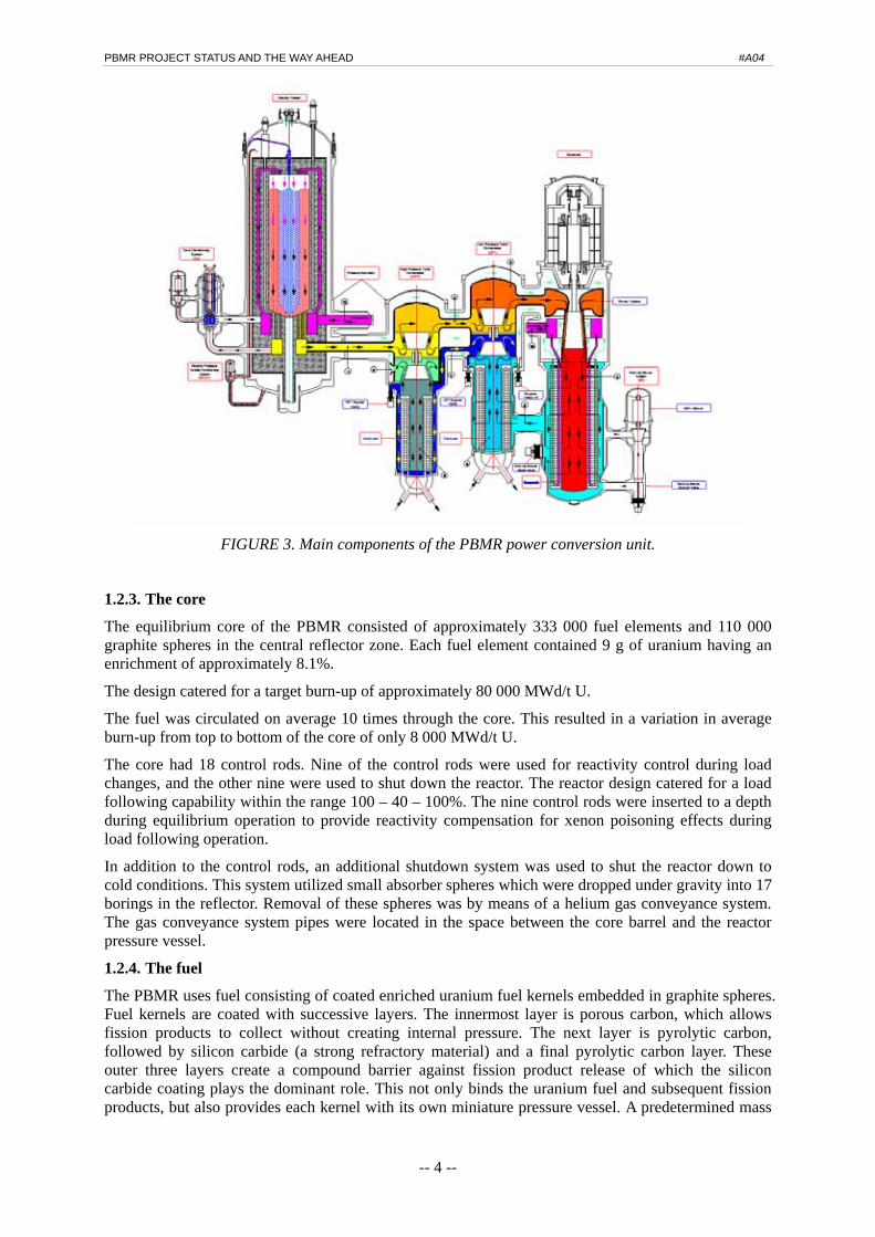
FIGURE 3. Main components of the PBMR power conversion unit.
1.2.3. The core
The equilibrium core of the PBMR consisted of approximately 333 000 fuel elements and 110 000 graphite spheres in the central reflector zone. Each fuel element contained 9 g of uranium having an enrichment of approximately 8.1%.
The design catered for a target burn-up of approximately 80 000 MWd/t U.
The fuel was circulated on average 10 times through the core. This resulted in a variation in average burn-up from top to bottom of the core of only 8 000 MWd/t U.
The core had 18 control rods. Nine of the control rods were used for reactivity control during load changes, and the other nine were used to shut down the reactor. The reactor design catered for a load following capability within the range 100 – 40 – 100%. The nine control rods were inserted to a depth during equilibrium operation to provide reactivity compensation for xenon poisoning effects during load following operation.
In addition to the control rods, an additional shutdown system was used to shut the reactor down to cold conditions. This system utilized small absorber spheres which were dropped under gravity into 17 borings in the reflector. Removal of these spheres was by means of a helium gas conveyance system. The gas conveyance system pipes were located in the space between the core barrel and the reactor pressure vessel.
1.2.4. The fuel
The PBMR uses fuel consisting of coated enriched uranium fuel kernels embedded in graphite spheres. Fuel kernels are coated with successive layers. The innermost layer is porous carbon, which allows fission products to collect without creating internal pressure. The next layer is pyrolytic carbon, followed by silicon carbide (a strong refractory material) and a final pyrolytic carbon layer. These outer three layers create a compound barrier against fission product release of which the silicon carbide coating plays the dominant role. This not only binds the uranium fuel and subsequent fission products, but also provides each kernel with its own miniature pressure vessel. A predetermined mass

HTR2004 Beijing, CHINA, 2004. 9.
-- 5 --
of these already ‘contained’ fuel particles (each now approximately 1 mm in diameter) is then embedded inside a 50 mm graphite sphere, which is then covered with a 5 mm fuel-free graphite layer. The graphite making up the sphere acts as a moderator, and the outer layer protects the fuel particles from mechanical effects, such as abrasion. This fuel element design has proved its ability to tolerate the PBMR operating envelope for extended periods in the German reactors, having been tested for 20 years. In terms of the goals set for inherent safety, this ‘packaging’ creates an efficient barrier against the release of activity (radioactive nuclides produced by fission) during all normal operations and postulated abnormal conditions. Managing the fuel as spherical ‘packages’ further ensures a reasonably homogeneous core, with a predictable density and temperature. FIGURE 4 shows the design of the fuel sphere.
FIGURE 4. The PBMR fuel sphere.
1.2.5. The Fuelling System
An on-line fuel and graphite sphere loading and unloading scheme was employed. Similar to the scheme employed in the German reactors, unloading of fuel was at the bottom of the reactor vessel. The 268 MWt design made use of a single discharge chute. A Core Unloading Device singularized the fuel and graphite spheres, whereafter it was assayed as fuel or graphite and for degree of burn-up. Reusable fuel was then returned to the annular core through nine evenly spaced fuelling tubes, and the graphite spheres through one tube to the centre of the core. The tubes penetrated the reactor vessel at the bottom and ran upwards in the space between the core barrel and the reactor pressure vessel. The flow rates of the fuel and graphite spheres were chosen to provide a core with graphite sphere central reflector and fuel annulus of the chosen dimensions. Spent fuel was routed to the spent fuel storage tanks.
2. POWER LEVEL OPTIMIZATIONS 2.1. Investigation of a Reactor Power Increase to 302 MWt
From the initial cost estimates obtained from the suppliers of main components, it was clear that the capital cost of the nth plant exceeded the initial targets by a large margin. The possibility of upgrading the power was then investigated. A Value Engineering Investigation was initiated to determine the extent to which the power could be upgraded within the general physical envelope of the 268 MWt reference design.
As a first investigation, the core thermo hydraulics were investigated. It was found that the core thermal power could be increased to 302 MWt within the same reactor pressure vessel inside diameter by reducing the outer reflector and thermal shield total thickness from 1 m to 0.9 m, and increasing the core effective height from 8.5 m to 9.04 m.

PBMR PROJECT STATUS AND THE WAY AHEAD #A04
-- 6 --
Secondly, a study on the Main Power System (MPS) was launched to establish the optimized MPS process parameters for this core power. The specific boundary conditions for this study were:
- The basic piping layout and pipe sizes were to be left unchanged.
- The upgrade should be performed within the existing interfaces of the Power Conversion Unit (PCU) pressure boundary.
The different options for obtaining the required MPS upgrade optimization included the following:
- Increasing the size of the turbo-machines to enable a higher mass flow rate through the reactor.
- Increasing the maximum pressure and therefore the fluid density in the MPS to obtain a higher mass flow rate through the reactor.
- Increasing the reactor outlet temperature to obtain a larger temperature difference across the reactor at approximately the same mass flow rate.
Based on the assumptions and results obtained during this techno-economic optimization, the most suitable option for the upgrading the reactor fluidic power to 302 MWt seemed to be:
- Increasing the system pressure to 8.5 MPa.
- Keeping the reactor outlet temperature at 900 °C.
- Keeping the overall pressure ratio as 2.8.
Following this investigation, further in-depth nuclear source term analyses showed that the core coolant bypassing the active core through the core structures and the graphite dynamic central reflector was in the order of 48%. Of this value, the leakage through the dynamic central reflector amounted to 28%. This bypass resulted in an increase of approximately 150 °C in the maximum operating fuel temperature. Since the diffusion coefficient of the fission products Ag and Cs through intact silicon carbide and the other coatings surrounding the fuel kernel is strongly dependent on the temperature, this increase in operating fuel temperature resulted in an increase in Ag and Cs releases during normal operation by two to three orders of magnitude compared to the 268 MWt reference design.
Further investigations confirmed that the increased Ag and Cs releases would result in contamination that would necessitate the use of remote handling equipment during maintenance operations on PCU components. A complete re-evaluation of the MPS design was therefore necessary.
2.2. Investigation of a Reactor Power Increase to 400 MWt
As stated before, the initial decision to implement the dynamic central reflector design was based on scarce knowledge of the behaviour of the graphite core structures under irradiation. At this stage, more insights on the graphite behaviour were becoming available, and it was clear that the core structures design had to provide for a mid-life replacement of the outer reflector part adjacent to the active core. An opportunity was then provided for considering a core with a fixed central reflector of a design that will provide for mid-life replacement of the part adjacent to the active core.
This decision was followed by a number of core neutronic-thermal-hydraulic investigations. The boundary conditions for these investigations were:
- The system pressure had to be increased to a maximum of 9.0 MPa.
- The reactor pressure vessel inner diameter shall remain the same as for the 268 MWt reference design.
- The thickness of the side reflector and thermal shield shall not be < 0.9 m
- The length of the core could be increased to a value which would be well within the value that could give rise to unstable xenon oscillations, and the pressure drop through the annular core should not exceed 300 kPa at maximum coolant flow rate.
- The maximum fuel operating temperature shall not exceed 1 130 °C.
The outcome of this investigation was a core with the following characteristics:

HTR2004 Beijing, CHINA, 2004. 9.
-- 7 --
- Core outer diameter of 3.7 m, a fixed central reflector with a diameter of 2.0 m and an effective nominal height of 11 m.
- A core thermal power of 400 MWt.
- A coolant flow of 185 kg/s resulting in a total core pressure drop of 291 kPa.
An additional core physics benefit gained from the use of a solid central reflector was the possibility to include reactivity control elements in the central reflector. It was then decided to redesign the placement of these elements with the objective of matching or improving on the shutdown capability of the 268 MWt reference design. The design of the design of this reactor unit is shown in FIGURE 5. Once the reactor power was set at 400 MWt, the thermal hydraulic cycle was optimized. Consequently, the following design point was recommended: - Reactor thermal power of 400 MWt - Reactor outlet temperature of 900 °C - Reactor inlet temperature of < 500 °C - PCU manifold pressure 9.0 MPa - Overall compressor pressure ratio of 3.2 - Cooling water design temperature of 28 °C - Cooling water design temperature range 1 °C to 41 °C The MPS for this design is shown in FIGURE 6.
FuellingPipes
ReactivityControlSystem(controlrods)
De-fuelChutes
(x3)
ReserveShutdown
System(small
absorberspheres
Annular Core
SideReflector
Cold GasInlet
Hot GasInlet
FIGURE 5. Reactor unit of the 400 MWt design with fixed central reflector.

PBMR PROJECT STATUS AND THE WAY AHEAD #A04
-- 8 --
Reactor Unit
CoreConditioningSystem
De-fuellingChutes (3x)
HPT
LPT
Generator
Recuperator
Intercooler
Pre-cooler
Core BarrelConditioningSystem
FIGURE 6. The main power system of the 400 MWt design.
3. REDESIGN OF POWER CONVERSION UNIT 3.1. Background
In following the systems engineering approach that is described as a logical sequence of activities and decisions that transforms the user requirement specification from the User into a licensed and commissioned PBMR facility ready for handover, the design reviews that are part of the logical sequence of activities are intensified during the basic design phase. These design reviews revealed some deficiencies in the three-shaft PCU design.
One such deficiency was that during a PCU trip and a simultaneous electrical fault on the generator, as well as with the possibility that the two turbo-compressors were not functioning, and with the uncertainty of whether the power turbine can function in the fourth quadrant as a compressor, a condition could be postulated that the primary coolant gas could not be circulated through the coolers. This would result in a condition where the rotational energy of the power turbine can only be expended through turbulences set up in between the rotor and stator, resulting in the heat up of the components. A simple energy balance showed that serious damage would be done to the power turbine itself in such an event.
3.2. Advantages of Redesign It was decided to redesign the PCU using a single power turbine-compressor shaft. This design change, undertaken jointly with strategic suppliers, had the following additional advantages: - The use of a horizontal turbo-compressor-generator layout to improve the seismic design. - Separation of the compressor and the power turbine casings using two dry gas seals at each
shaft-casing penetration to separate the high-maintenance area from the low-maintenance area. - The use of oil lubricated bearings instead of electromagnetic bearings. - The use of a mechanical gearbox to allow higher speed smaller size turbo-machinery and
conversion from 50 Hz to 60 Hz operation is simplified.

HTR2004 Beijing, CHINA, 2004. 9.
-- 9 --
- No start-up blower system is required, since the Brayton cycle can be started using the generator as a motor.
- The generator can be orientated so that in a rotor failure event, the trajectory of missiles generated in such an instance is not directed towards the reactor unit.
- Elimination of approximately 1 000 electromagnetic bearing penetrations of pressure boundary.
- Elimination of potential Power Turbine Generator unstable operations during trip with certain component failures occurring simultaneously.
- Less complex control system.
- Easier to balance shaft thrust forces.
- No large resistor bank required to maintain load on trip.
- Improved maintenance very similar to combustion gas turbine systems.
- No special rotor balancing facilities are required; conventional commissioning sequences can be followed.
- Reduced cost of turbo machinery equipment.
- Significantly lower Research and Development (R&D) required, i.e. lower development risk.
3.3. Schematic Diagram and Revised Layout
FIGURE 7 shows the schematic diagram of the new PCU configuration. FIGURE 8 shows the layout of the new PCU. The layout in the building is shown in FIGURE 9.
FIGURE 7. Schematic diagram of the single shaft power conversion unit.

PBMR PROJECT STATUS AND THE WAY AHEAD #A04
-- 10 --
Reactor Unit
Recuperators
Compressors Turbine
Pre-cooler Intercooler
Gearbox
Generator
FIGURE 8. Physical layout of the new PCU.
FIGURE 9. The 400 MWt single shaft main power system in the building.
4. THE RSA PROJECT RELEASE STATUS - The South Africa government has designated PBMR a National Strategic Project
- Cabinet level committee appointed (February 2004) - Official announcement of full launch planned (September 2004)
- Project being restructured - Governance being transferred to Department of Trade and Industry - Board being reconstituted

HTR2004 Beijing, CHINA, 2004. 9.
-- 11 --
- New Board Chairman already appointed - Progress on regulatory front
- Approach to Key Licensing Issues agreed by December 2004 - Safety Analysis Report, Rev. 2 being prepared in format of Reg. Guide 1.70 with a target
date of January 2006 for handover to the Regulator - Appeals to Environmental Impact Assessment positive Record of Decision being
dispositioned (December 2004) - Work at Koeberg site
- Site preparation to start in the second quarter of 2007 - Construction to start in April 2007
5. THE PBMR AS THE NGNP IN THE INL PROJECT
5.1. Organizational Background
PBMR has developed a conceptual design for the Next Generation Nuclear Plant (NGNP) layout according to the requirements as set out in the NGNP High-Level Functions and Requirements document issued by the Department of Energy (DOE) in September 2003 [2]. PBMR has presented this conceptual layout together with the principal design philosophy of the Pebble Bed technology to the DOE appointed Independent Technical Review Group (ITRG) on two separate occasions. The first presentation was made to the ITRG in August 2003, and a follow-up presentation was made in San Diego during the last week of February 2004. PBMR has since joined a US-based Consortium led by Westinghouse Electric Company. The principal members of the consortium include Sargent & Lundy LLC, Air Products and Chemicals Inc., the Shaw Group, and the Bell Company. Westinghouse Electric Company submitted a response to the DOE Request for Expressions of Interest concerning the NGNP project. The consortium have expressed their interest and commitment to participate in making the NGNP a success for the DOE, INL and the commercial nuclear industry. The PBMR INL bid also enjoys the support of the South African government.
5.2. PBMR as an NGNP
Some preliminary sizing calculations were performed for using the PBMR as a heat source for the NGNP INL project. The scoping design was for taking off 50 MWt from the reactor outlet pipe by means of a full-flow intermediate heat exchanger. FIGURE 10 shows this arrangement in the PBMR PCU.
FIGURE 10. The intermediate heat exchanger installed in the reactor outlet pipe.

PBMR PROJECT STATUS AND THE WAY AHEAD #A04
-- 12 --
6. FUTURE TECHNOLOGY GROWTH PATH
6.1. Background
The development of new generation advanced nuclear power plants will follow the same basic sequence as that followed by other industries and products. The initial design will prove the basic viability of the concept both technically and economically. Then as the marketplace responds, further developments will improve and enhance the product line, providing even greater value to the customer. The PBMR has already begun that cycle.
This section provides a look into the future for the PBMR design. It is an exciting future, as one would expect for an advanced reactor capable of multiple missions and scaleable configurations. The plant as described in the previous sections will be termed ‘Demonstration Reference Plant’ in the following sections.
6.2. Technology Growth Path
The PBMR technology path has substantial potential beyond the initial Demonstration Reference Plant capabilities to be applied in early deployments for electrical generation. There are several major steps that take the plant up to and beyond the definition of VHTR plants.
The growth path shown in FIGURE 11 is a direct application of the Demonstration Reference Plant from a physical building, support systems and equipment layout perspective, and a logical development in high-temperature materials, turbo-machinery evolution and advanced fuels within the same physical boundaries. The eventual design goal is then summarized as follows:
- Pebble fuel for Reactor Outlet Temperature (ROT) ~1 200 °C - Reactor power of ~600 MWt - Direct Brayton cycle with 300 MWe net output - High-power density in PCU achieved by high-speed turbo machinery
To accommodate the higher reactor power and the increased ROT, Carbon Fibre Reinforced Carbon (CFRC) materials will have to be used for a number of components such as:
- The hot duct liners of the hot pipes - The turbine disc and blades - The control rods
PBMR has defined an existing technology programme to extend the capabilities of the Demonstration Reference Plant beyond the initial commercial objectives. The programme currently contains:
- Fuel Performance Modelling - Advanced Fuel - Advanced Metallic and Ceramic Materials - Components Improvements and Testing - Advanced Modelling and Design Capability - High-level Waste Minimization
These programmes will be driven first by their relevance to the Demonstration Reference Plant programme. The PBMR enterprise is built around the objective of getting a safe, high-quality product developed and delivered as early as possible to the marketplace. Once that is completed and the Demonstration Reference Plant is taken to market, substantial work can be pursued to improve on the base design.

HTR2004 Beijing, CHINA, 2004. 9.
-- 13 --
400 MWt950oC
400 MWt1200oC
600 MWt>1200oC
- Safety Case- IHX Hydrogen Process- Codes and Standards (60 y)
- Fuel- Control Rods- Graphite Lifetime- RPV and Core Barrel Material- Reactor Outlet Pipe Liner- Turbine Blade/Disc Material Development- Material and Component Qualification- Codes and Standards (60 y)
- Fuel-Graphite Lifetime- Optimization
of Commercial Margins
Current TechnologyRegime
Future TechnologyRegime
Technology Threshold
FIGURE 11. Conceptual VHTR migration path for PBMR.
7. CONCLUSION The Pebble Bed Modular Reactor is a first-of-a-kind plant with attributes that make it ideally suited for development into a plant that will fulfil the specified requirements for Generation IV reactors. It is also easily adaptable to be used in the Next Generation Nuclear Plant as a heat source for the hydrogen production demonstration facility planned on the Idaho site in the United States.
ACKNOWLEDGEMENT The author wishes to express his appreciation to PBMR (Pty) Ltd for allowing publication of this document.
REFERENCES [1] AVR- Experimental High-Temperature Reactor. 21 Years of Successful Operation for a Future
Energy Technology. Association of German Engineers (VDI) - The Society for Energy Technologies (Publ.) 1990.
[2] Next Generation Nuclear Pant - High-Level Functions and Requirements, September 2003, John M Ryskamp, Edwin A Harvego, Edward J Gorski, Hans-Wolfgang Chi, Soli T Khericha, Sten A Caspersson, George A Beitel.
Richard S TurkINEEL/EXT-03-01163 September 2003.
AUTHOR INTRODUCTION The author is currently employed by the company PBMR (Pty) Ltd, in the capacity of Power Plant Delivery Director.


![[email protected] - PBMR](https://img.pdfslide.net/doc/110x75/6206218f8c2f7b173004c5ff/emailprotected-pbmr.jpg)