Embed Size (px)
Citation preview
Physics with many positrons:positron sources and positron beams
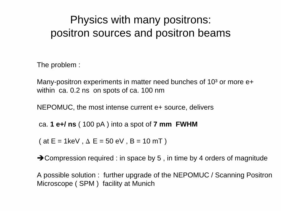
The problem :
Many-positron experiments in matter need bunches of 10³ or more e+within ca. 0.2 ns on spots of ca. 100 nm
NEPOMUC, the most intense current e+ source, delivers
ca. 1 e+/ ns ( 100 pA ) into a spot of 7 mm FWHM
( at E = 1keV , D E = 50 eV , B = 10 mT )
Compression required : in space by 5 , in time by 4 orders of magnitude
A possible solution : further upgrade of the NEPOMUC / Scanning PositronMicroscope ( SPM ) facility at Munich
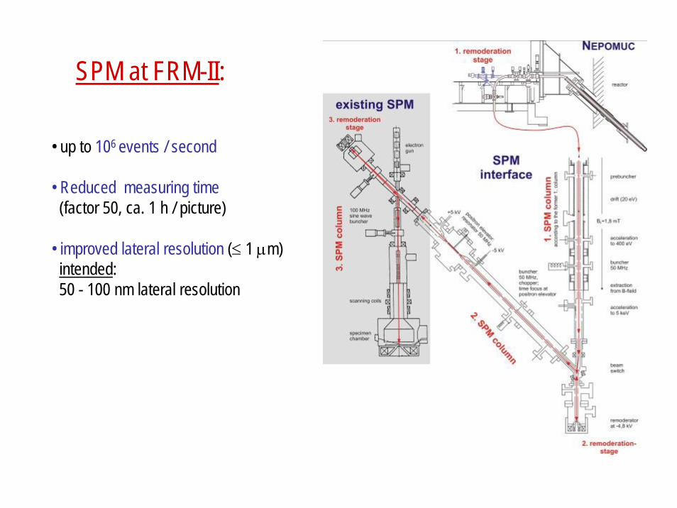
SPM at FRM-II:
• up to 106 events / second
• Reduced measuring time (factor 50, ca. 1 h / picture)
• improved lateral resolution (≤ 1 μm)intended: 50 - 100 nm lateral resolution
G. Kögel : Remarks on particle optics
( Phase space, paraxial optics, aberration correction, bunching, remoderation )
Case study of the Munich Positron Microscope
( Various beam lines, remoderation stages, application ofoptical principles in design and construction,outlook to many positron pulses )
Ch. Hugenschmidt : Positron sources, positron beams
W. Egger : Applications of pulsed positron beams
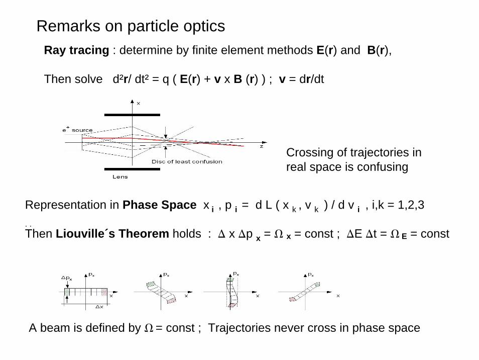
Remarks on particle opticsRay tracing : determine by finite element methods E(r) and B(r),
Then solve d²r/ dt² = q ( E(r) + v x B (r) ) ; v = dr/dt
Crossing of trajectories in real space is confusing
Representation in Phase Space x i , p i = d L ( x k , v k ) / d v i , i,k = 1,2,3. . Then Liouville´s Theorem holds : D x Dp x = W x = const ; DE Dt = W E = const
A beam is defined by W = const ; Trajectories never cross in phase space
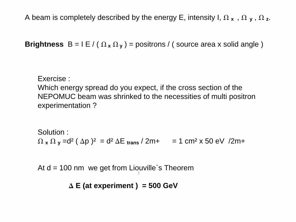
A beam is completely described by the energy E, intensity I, W x , W y , W z.
Brightness B = I E / ( W x W y ) = positrons / ( source area x solid angle )
Exercise : Which energy spread do you expect, if the cross section of theNEPOMUC beam was shrinked to the necessities of multi positronexperimentation ?
Solution : W x W y =d² ( Dp )² = d² DE trans / 2m+ = 1 cm² x 50 eV /2m+
At d = 100 nm we get from Liouville`s Theorem
D E (at experiment ) = 500 GeV
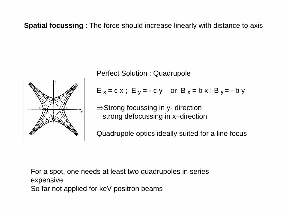
Spatial focussing : The force should increase linearly with distance to axis
Perfect Solution : Quadrupole
E x = c x ; E y = - c y or B x = b x ; B y = - b y
⇒Strong focussing in y- directionstrong defocussing in x–direction
Quadrupole optics ideally suited for a line focus
For a spot, one needs at least two quadrupoles in seriesexpensiveSo far not applied for keV positron beams
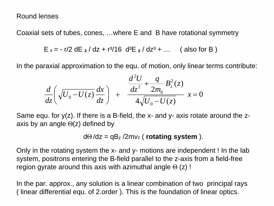
Round lenses
Coaxial sets of tubes, cones, …where E and B have rotational symmetry
E r = - r/2 dE z / dz + r³/16 d³E z / dz³ + … ( also for B )
In the paraxial approximation to the equ. of motion, only linear terms contribute:
Same equ. for y(z). If there is a B-field, the x- and y- axis rotate around the z-axis by an angle Q(z) defined by
dQ /dz = qBz /2mvz ( rotating system ).
Only in the rotating system the x- and y- motions are independent ! In the lab system, positrons entering the B-field parallel to the z-axis from a field-free region gyrate around this axis with azimuthal angle Q (z) !
In the par. approx., any solution is a linear combination of two principal rays( linear differential equ. of 2.order ). This is the foundation of linear optics.
0)(4
)(2)(0
2
02
2
0 =−
++⎟
⎠⎞
⎜⎝⎛ − x
zUU
zBmq
dzUd
dzdxzUU
dzd z
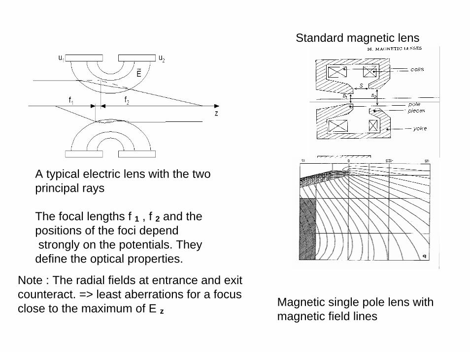
A typical electric lens with the twoprincipal rays
The focal lengths f 1 , f 2 and thepositions of the foci dependstrongly on the potentials. Theydefine the optical properties.
Magnetic single pole lens withmagnetic field lines
Standard magnetic lens
Note : The radial fields at entrance and exitcounteract. => least aberrations for a focusclose to the maximum of E z
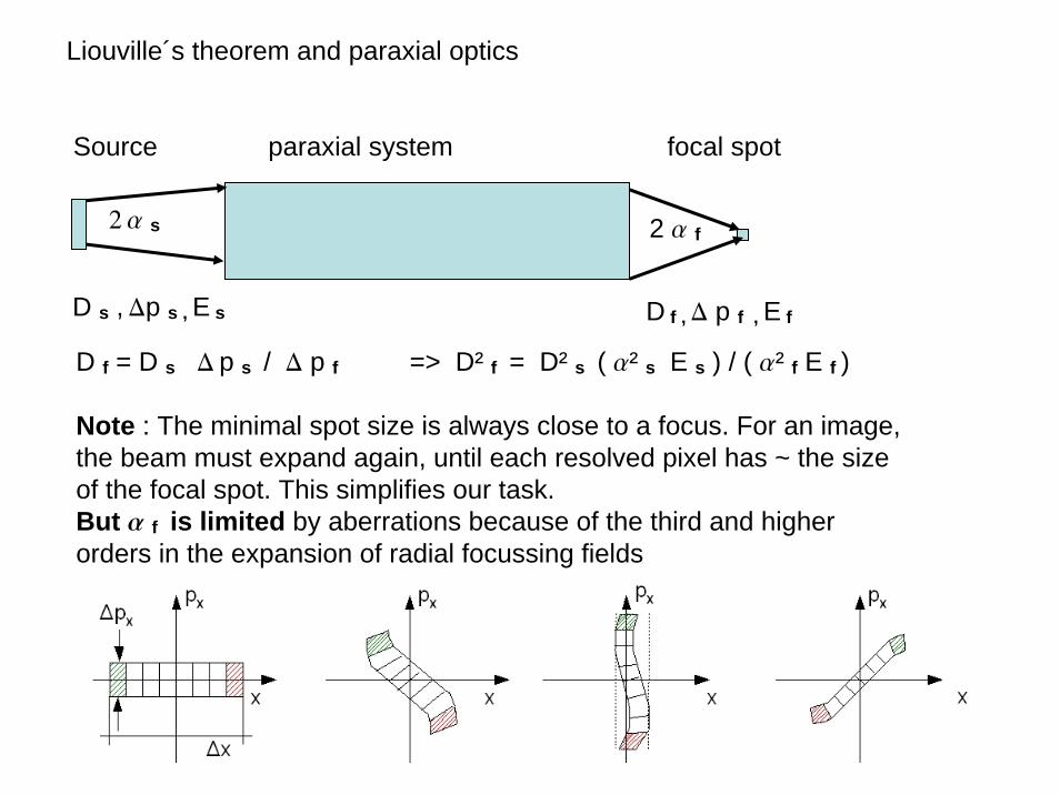
Liouville´s theorem and paraxial optics
Source paraxial system focal spot
2 a s 2 a f
D s , Dp s , E s D f , D p f , E f
D f = D s D p s / D p f => D² f = D² s ( a² s E s ) / ( a² f E f )
Note : The minimal spot size is always close to a focus. For an image, the beam must expand again, until each resolved pixel has ~ the sizeof the focal spot. This simplifies our task.But a f is limited by aberrations because of the third and higherorders in the expansion of radial focussing fields
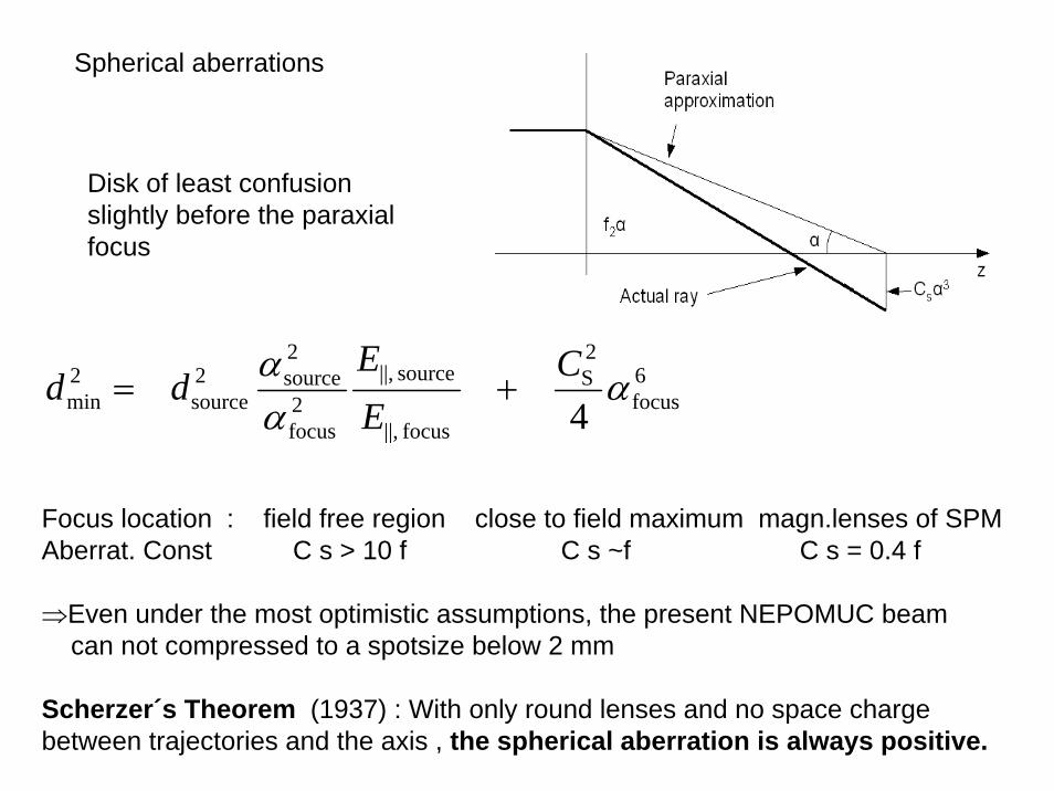
Spherical aberrations
Disk of least confusionslightly before the paraxialfocus
Focus location : field free region close to field maximum magn.lenses of SPMAberrat. Const C s > 10 f C s ~f C s = 0.4 f
⇒Even under the most optimistic assumptions, the present NEPOMUC beamcan not compressed to a spotsize below 2 mm
Scherzer´s Theorem (1937) : With only round lenses and no space chargebetween trajectories and the axis , the spherical aberration is always positive.
6focus
2S
focus||,
source||,2focus
2source2
source2min 4
ααα C
EE
dd +=
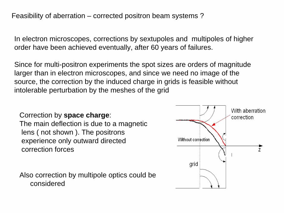
Feasibility of aberration – corrected positron beam systems ?
In electron microscopes, corrections by sextupoles and multipoles of higherorder have been achieved eventually, after 60 years of failures.
Since for multi-positron experiments the spot sizes are orders of magnitudelarger than in electron microscopes, and since we need no image of thesource, the correction by the induced charge in grids is feasible withoutintolerable perturbation by the meshes of the grid
Correction by space charge:The main deflection is due to a magneticlens ( not shown ). The positronsexperience only outward directedcorrection forces
Also correction by multipole optics could beconsidered
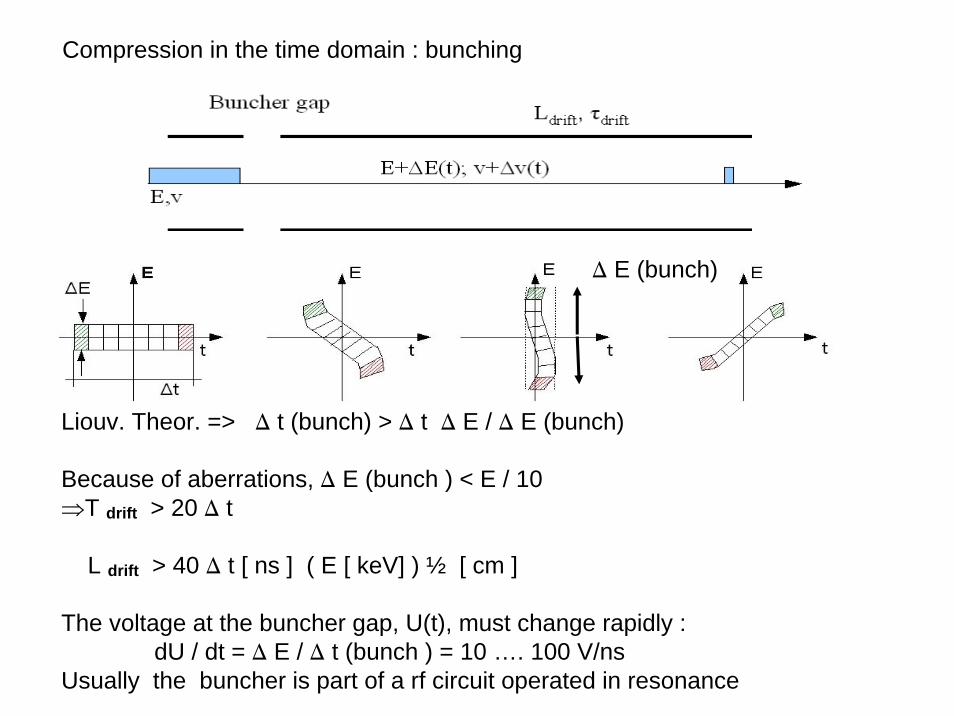
Compression in the time domain : bunching
Liouv. Theor. => D t (bunch) > D t D E / D E (bunch)
Because of aberrations, D E (bunch ) < E / 10⇒T drift > 20 D t
L drift > 40 D t [ ns ] ( E [ keV] ) ½ [ cm ]
The voltage at the buncher gap, U(t), must change rapidly :dU / dt = D E / D t (bunch ) = 10 …. 100 V/ns
Usually the buncher is part of a rf circuit operated in resonance
D E (bunch)
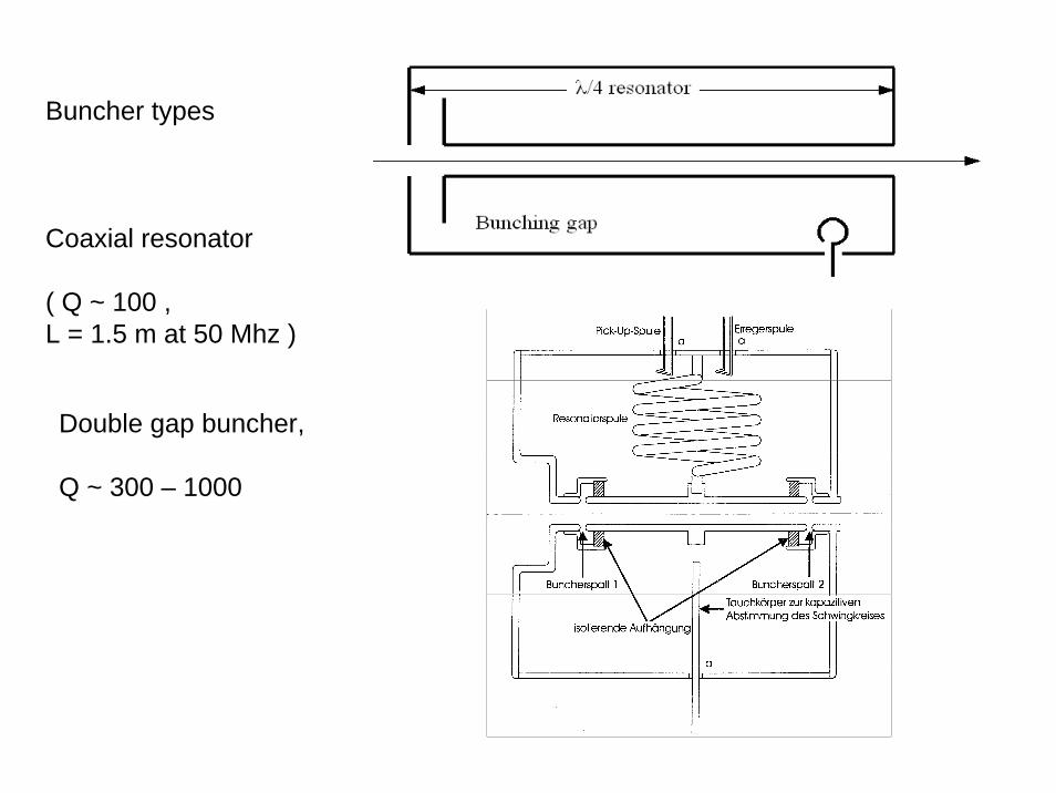
Buncher types
Coaxial resonator
( Q ~ 100 , L = 1.5 m at 50 Mhz )
Double gap buncher,
Q ~ 300 – 1000
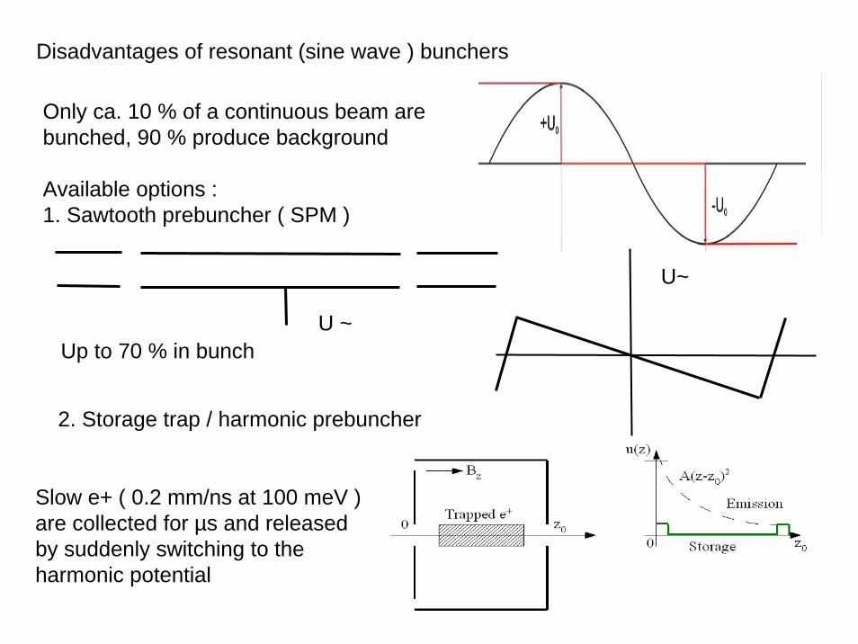
Disadvantages of resonant (sine wave ) bunchers
Only ca. 10 % of a continuous beam arebunched, 90 % produce background
Available options :1. Sawtooth prebuncher ( SPM )
U ~
U~
Up to 70 % in bunch
2. Storage trap / harmonic prebuncher
Slow e+ ( 0.2 mm/ns at 100 meV ) are collected for µs and releasedby suddenly switching to theharmonic potential
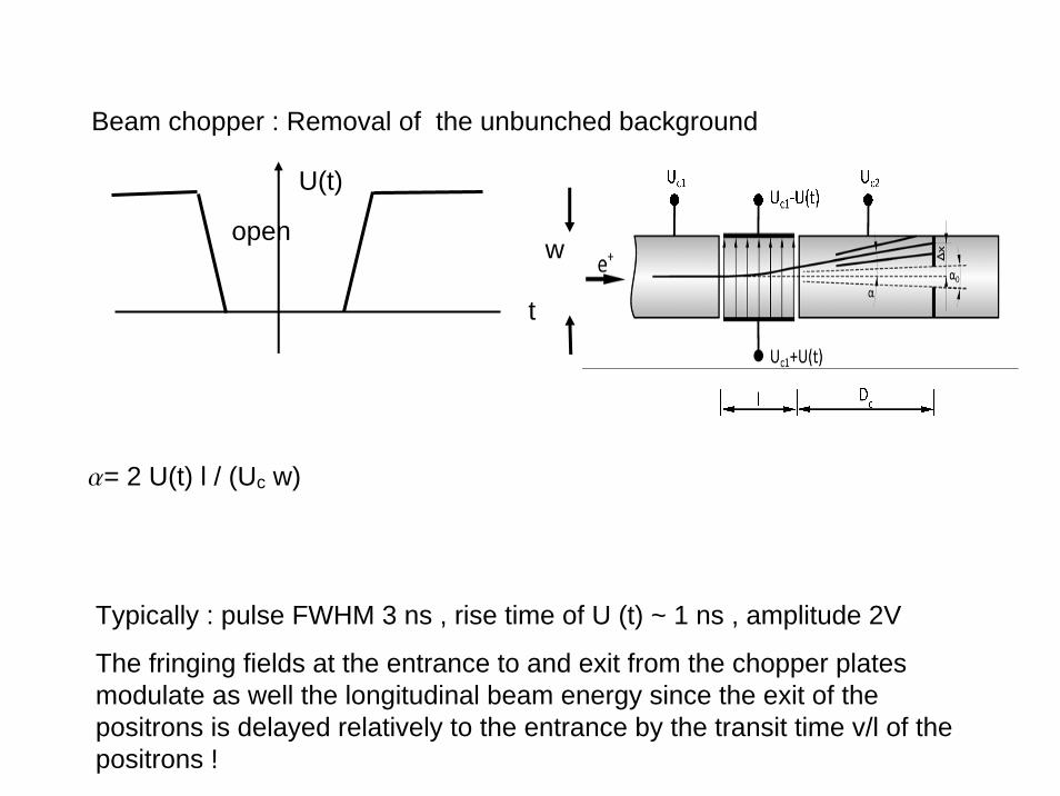
Beam chopper : Removal of the unbunched background
U(t)
open
t
a= 2 U(t) l / (Uc w)
Typically : pulse FWHM 3 ns , rise time of U (t) ~ 1 ns , amplitude 2V
The fringing fields at the entrance to and exit from the chopper platesmodulate as well the longitudinal beam energy since the exit of thepositrons is delayed relatively to the entrance by the transit time v/l of thepositrons !
w
End of the tutorial introduction into fundamentals of particle opticsand functional elements of the Munich positron beams
Conclusion
Without new tools from outside the range of traditional particle optics, there is no chance for true multi-positron experiments, at least at NEPOMUC .
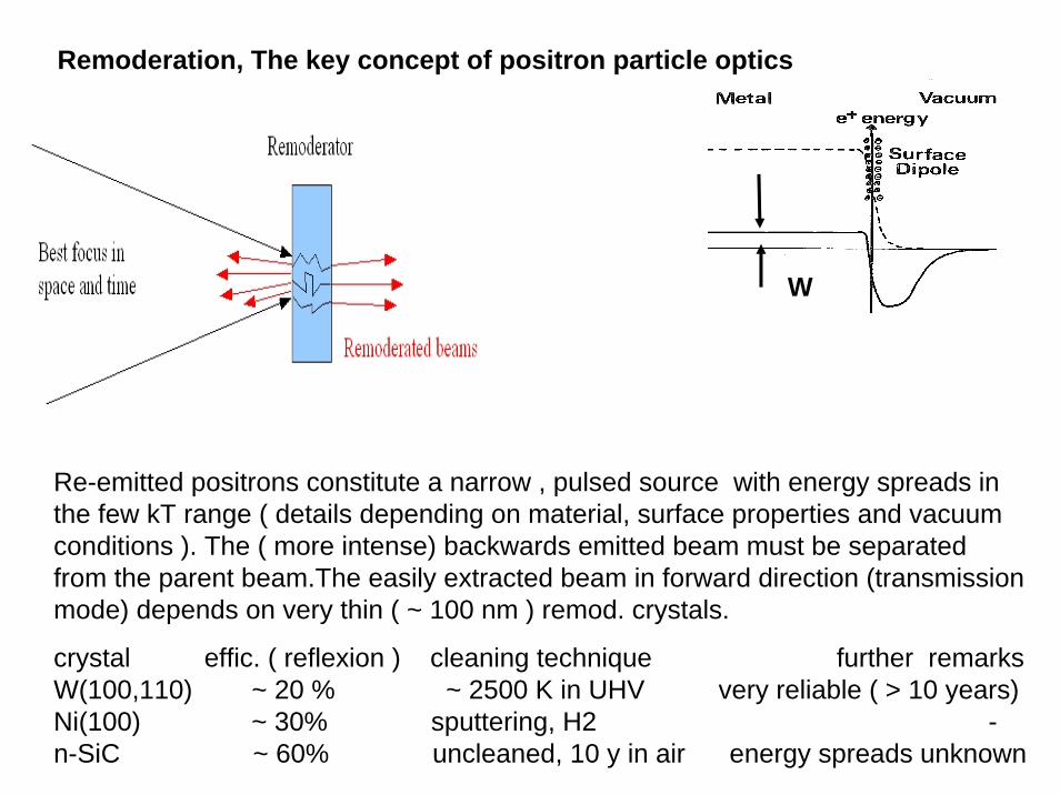
Remoderation, The key concept of positron particle optics
W
Re-emitted positrons constitute a narrow , pulsed source with energy spreads in the few kT range ( details depending on material, surface properties and vacuumconditions ). The ( more intense) backwards emitted beam must be separatedfrom the parent beam.The easily extracted beam in forward direction (transmissionmode) depends on very thin ( ~ 100 nm ) remod. crystals.
crystal effic. ( reflexion ) cleaning technique further remarksW(100,110) ~ 20 % ~ 2500 K in UHV very reliable ( > 10 years) Ni(100) ~ 30% sputtering, H2 -n-SiC ~ 60% uncleaned, 10 y in air energy spreads unknown
Summary on particle optics in relation to positron experiments
Phase space considerations give us a reliable, simple insight into thefeasibility of a project or the usefulness of existing parts.
Numerical simulations ( ray tracing )are only needed for the optimization of critical components, e.g. spot forming lenses.
The main handicap of positron beam physics is the low brightness of allpositron sources (when compared to electron sources)
This is partially compensated by remoderation of positrons. Also correctionof spherical aberration should be more efficient and less expensive as in electron optics.
To remove the enormous adiabatic heating of the beam due to thecompression in an ( optical ) beam system , a sequence of remoderationstages is necessary for spots / pulses in the sub µm / sub ns region. Thisintroduces dramatic losses in intensity. There is an urgent need forcoordinated research into better and more efficient moderators .
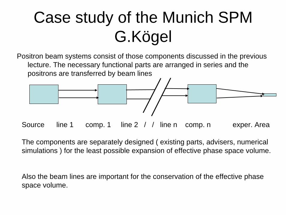
Case study of the Munich SPMG.Kögel
Positron beam systems consist of those components discussed in the previouslecture. The necessary functional parts are arranged in series and thepositrons are transferred by beam lines
Source line 1 comp. 1 line 2 / / line n comp. n exper. Area
The components are separately designed ( existing parts, advisers, numericalsimulations ) for the least possible expansion of effective phase space volume.
Also the beam lines are important for the conservation of the effective phasespace volume.
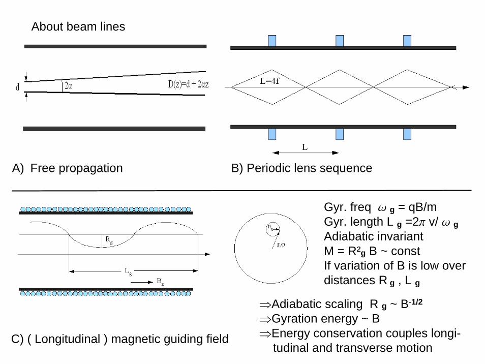
About beam lines
A) Free propagation B) Periodic lens sequence
C) ( Longitudinal ) magnetic guiding field
Gyr. freq w g = qB/mGyr. length L g =2p v/ w gAdiabatic invariantM = R²g B ~ constIf variation of B is low overdistances R g , L g
⇒Adiabatic scaling R g ~ B-1/2
⇒Gyration energy ~ B⇒Energy conservation couples longi-
tudinal and transverse motion
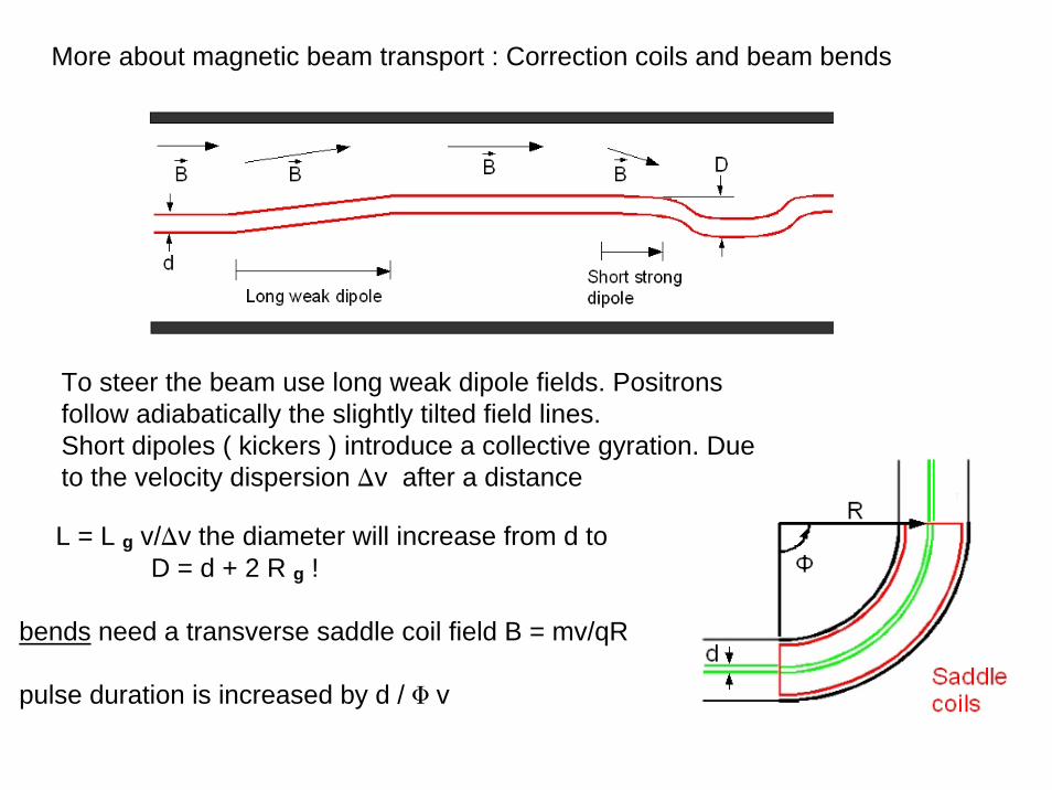
More about magnetic beam transport : Correction coils and beam bends
To steer the beam use long weak dipole fields. Positronsfollow adiabatically the slightly tilted field lines.Short dipoles ( kickers ) introduce a collective gyration. Dueto the velocity dispersion Dv after a distance
L = L g v/Dv the diameter will increase from d toD = d + 2 R g !
bends need a transverse saddle coil field B = mv/qR
pulse duration is increased by d / F v
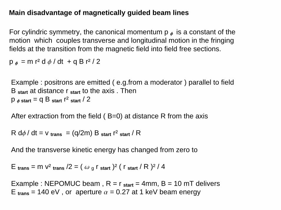
Main disadvantage of magnetically guided beam lines
For cylindric symmetry, the canonical momentum p f is a constant of themotion which couples transverse and longitudinal motion in the fringingfields at the transition from the magnetic field into field free sections.
p f = m r² d f / dt + q B r² / 2
Example : positrons are emitted ( e.g.from a moderator ) parallel to fieldB start at distance r start to the axis . Thenp f start = q B start r² start / 2
After extraction from the field ( B=0) at distance R from the axis
R df / dt = v trans = (q/2m) B start r² start / R
And the transverse kinetic energy has changed from zero to
E trans = m v² trans /2 = ( w g r start )² ( r start / R )² / 4
Example : NEPOMUC beam , R = r start = 4mm, B = 10 mT deliversE trans = 140 eV , or aperture a = 0.27 at 1 keV beam energy
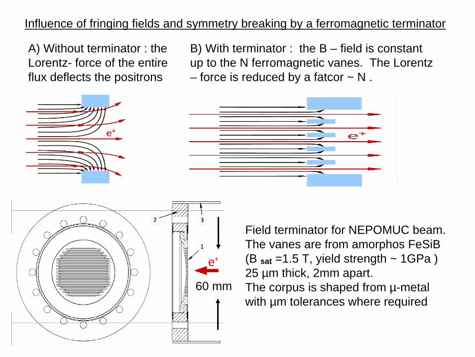
Influence of fringing fields and symmetry breaking by a ferromagnetic terminator
A) Without terminator : theLorentz- force of the entireflux deflects the positrons
B) With terminator : the B – field is constantup to the N ferromagnetic vanes. The Lorentz – force is reduced by a fatcor ~ N .
60 mm
Field terminator for NEPOMUC beam. The vanes are from amorphos FeSiB(B sat =1.5 T, yield strength ~ 1GPa )25 µm thick, 2mm apart.The corpus is shaped from µ-metalwith µm tolerances where required
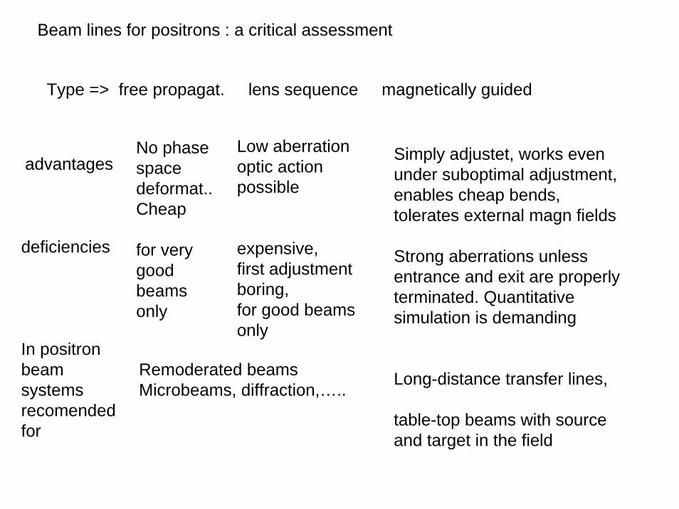
Beam lines for positrons : a critical assessment
Type => free propagat. lens sequence magnetically guided
advantagesLow aberrationoptic actionpossible
expensive, first adjustmentboring, for good beamsonly
Simply adjustet, works evenunder suboptimal adjustment,enables cheap bends, tolerates external magn fields
Strong aberrations unlessentrance and exit are properlyterminated. Quantitative simulation is demanding
Long-distance transfer lines,
table-top beams with sourceand target in the field
deficiencies
In positronbeamsystemsrecomendedfor
Remoderated beamsMicrobeams, diffraction,…..
No phasespacedeformat.. Cheap
for verygood beamsonly
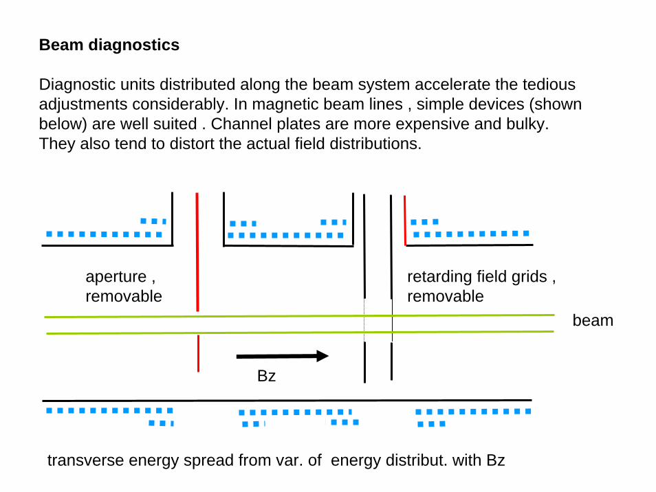
Beam diagnostics
Diagnostic units distributed along the beam system accelerate the tediousadjustments considerably. In magnetic beam lines , simple devices (shownbelow) are well suited . Channel plates are more expensive and bulky. They also tend to distort the actual field distributions.
beam
retarding field grids , removable
aperture , removable
transverse energy spread from var. of energy distribut. with Bz
Bz
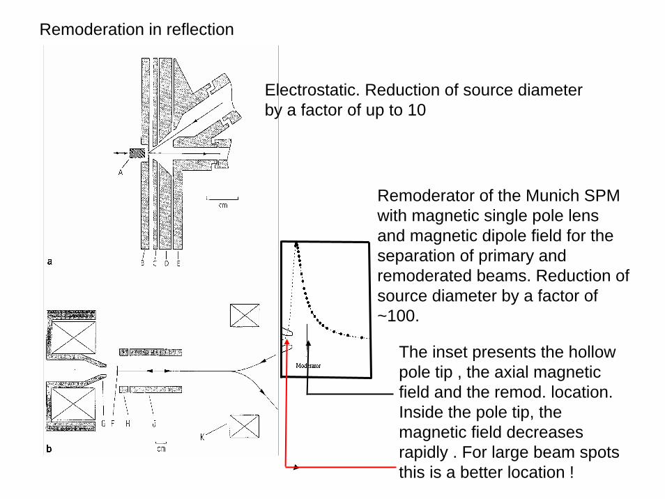
Remoderation in reflection
Electrostatic. Reduction of source diameterby a factor of up to 10
Remoderator of the Munich SPM with magnetic single pole lensand magnetic dipole field for theseparation of primary and remoderated beams. Reduction of source diameter by a factor of ~100.
The inset presents the hollowpole tip , the axial magneticfield and the remod. location. Inside the pole tip, themagnetic field decreasesrapidly . For large beam spotsthis is a better location !
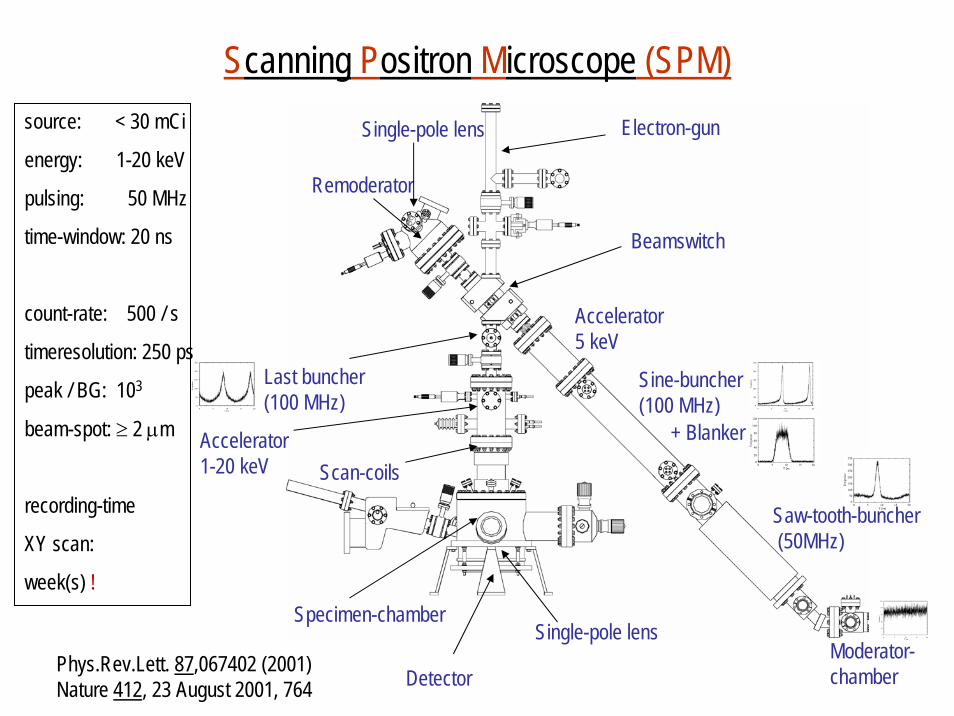
Scanning Positron Microscope (SPM)
Moderator-chamber
Saw-tooth-buncher(50MHz)
Sine-buncher(100 MHz)
Accelerator5 keV
Beamswitch
Remoderator
Last buncher(100 MHz)
+ Blanker
Single-pole lens
Accelerator1-20 keV
Single-pole lens
Scan-coils
Electron-gun
Specimen-chamber
DetectorPhys.Rev.Lett. 87,067402 (2001)Nature 412, 23 August 2001, 764
source: < 30 mCi
energy: 1-20 keV
pulsing: 50 MHz
time-window: 20 ns
count-rate: 500 / s
timeresolution: 250 ps
peak / BG: 103
beam-spot: ≥ 2 μm
recording-time
XY scan:
week(s) !
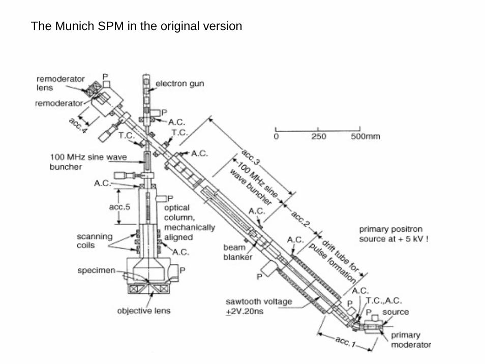
The Munich SPM in the original version
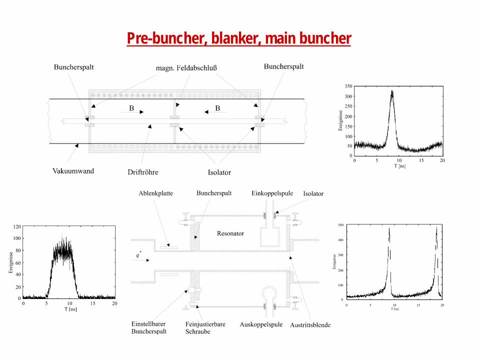
Pre-buncher, blanker, main buncher
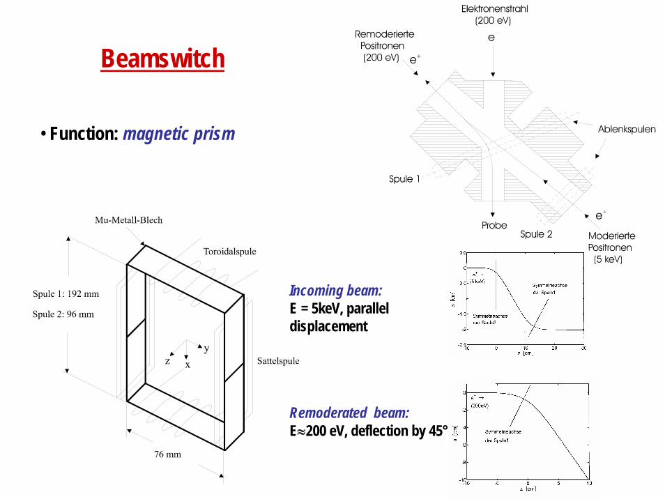
Beamswitch
• Function: magnetic prism
Incoming beam:E = 5keV, parallel displacement
Remoderated beam:E≈200 eV, deflection by 45°
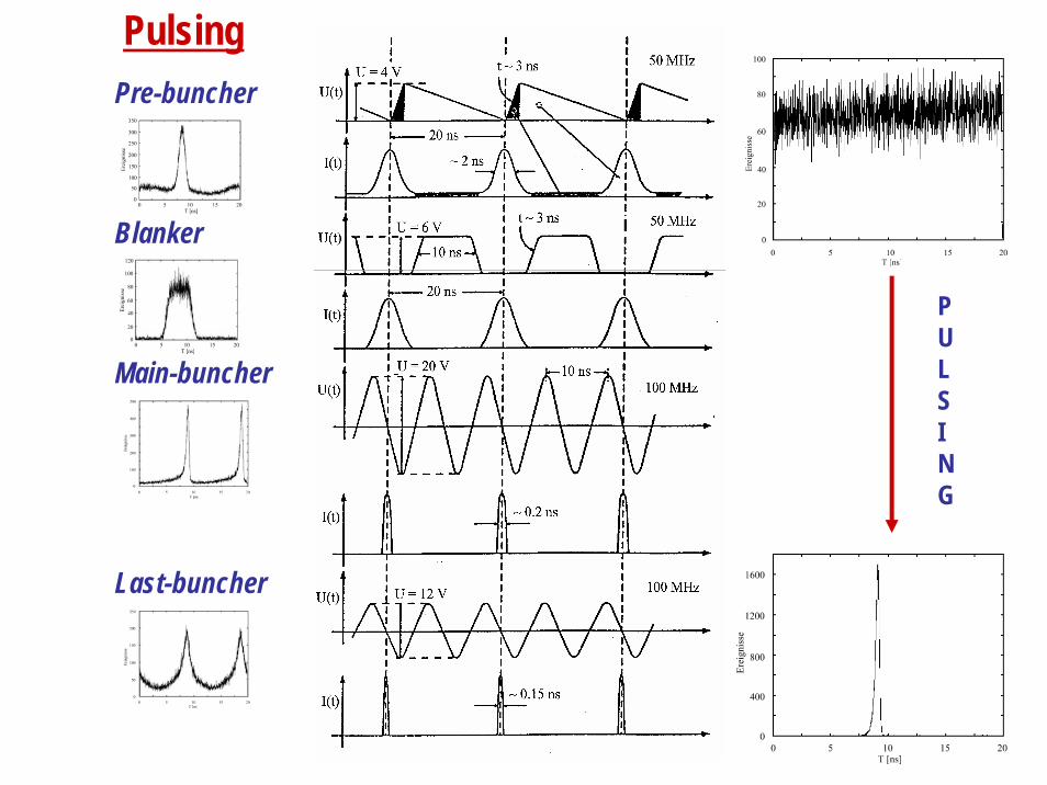
PulsingPre-buncher
Blanker
Main-buncher
Last-buncher
PULSING
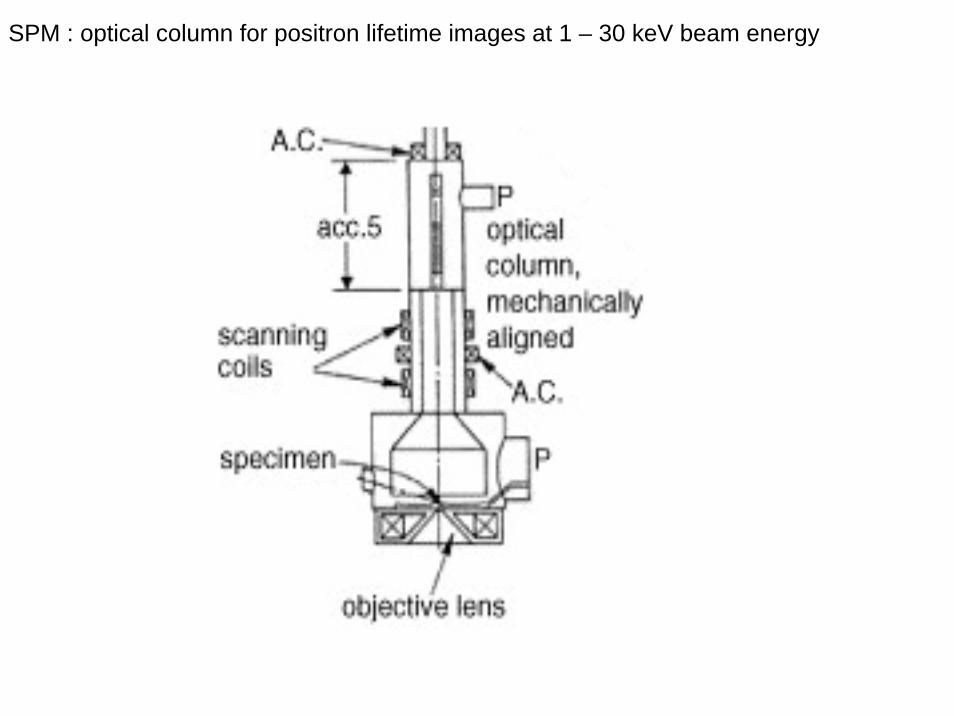
SPM : optical column for positron lifetime images at 1 – 30 keV beam energy
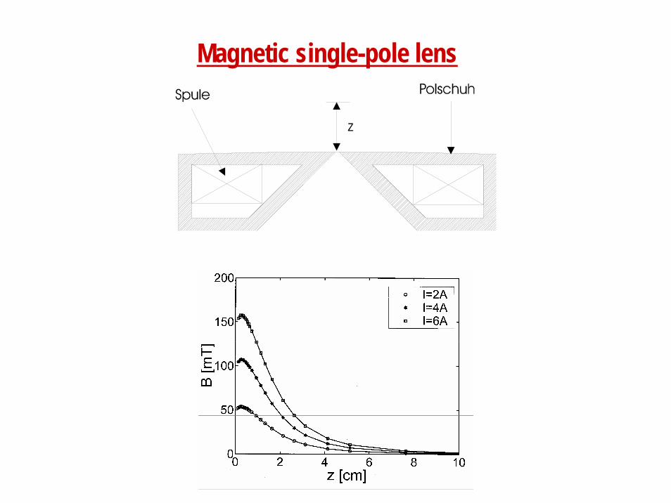
Magnetic single-pole lens
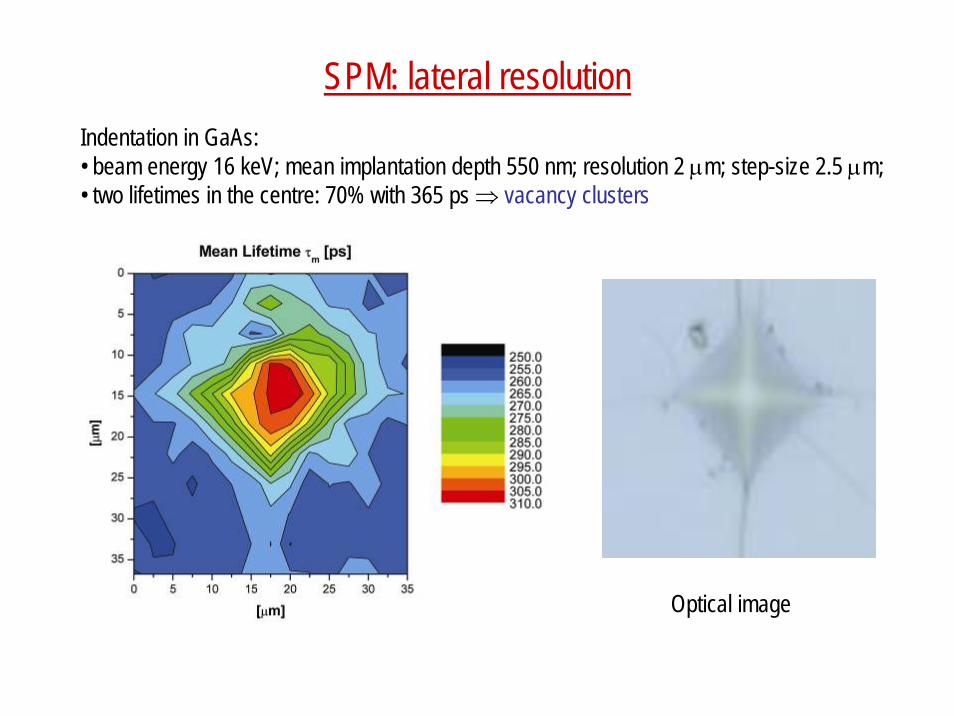
SPM: lateral resolution
Optical image
Indentation in GaAs: • beam energy 16 keV; mean implantation depth 550 nm; resolution 2 μm; step-size 2.5 μm;• two lifetimes in the centre: 70% with 365 ps ⇒ vacancy clusters
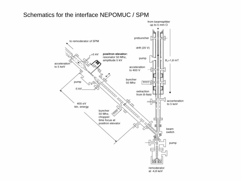
Schematics for the interface NEPOMUC / SPM
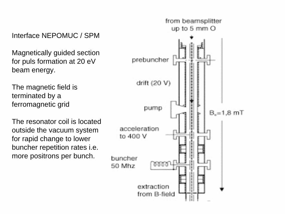
Interface NEPOMUC / SPM
Magnetically guided sectionfor puls formation at 20 eVbeam energy.
The magnetic field isterminated by a ferromagnetic grid
The resonator coil is locatedoutside the vacuum systemfor rapid change to lowerbuncher repetition rates i.e. more positrons per bunch.
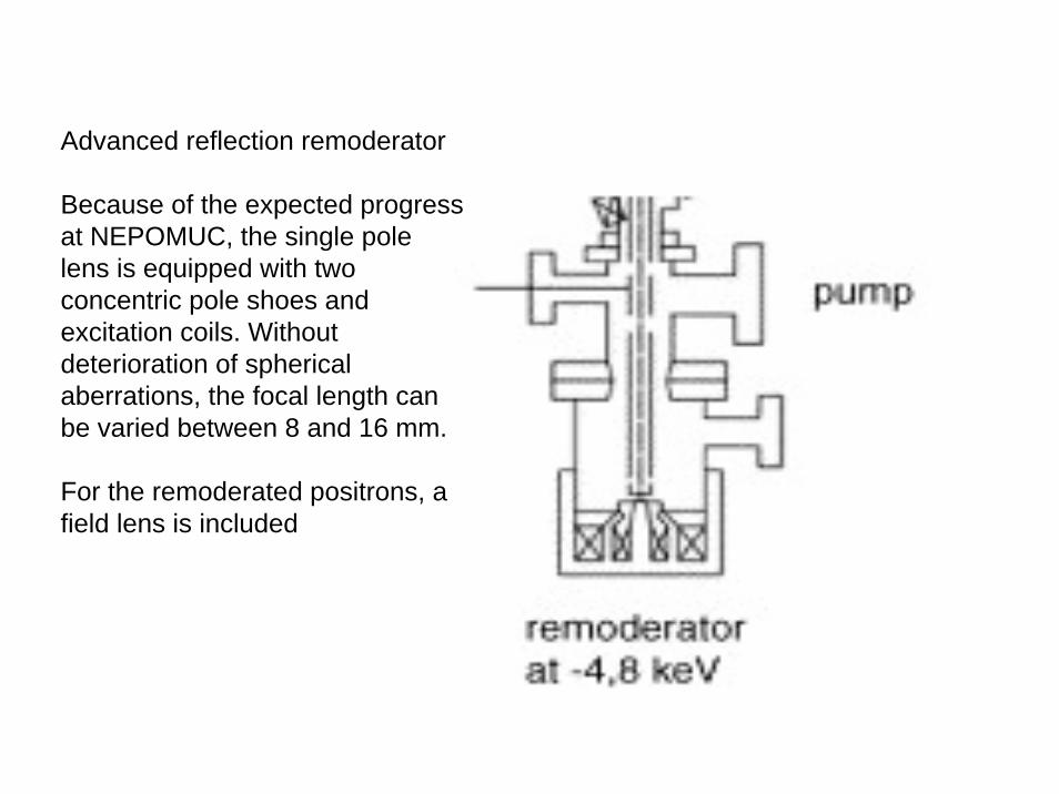
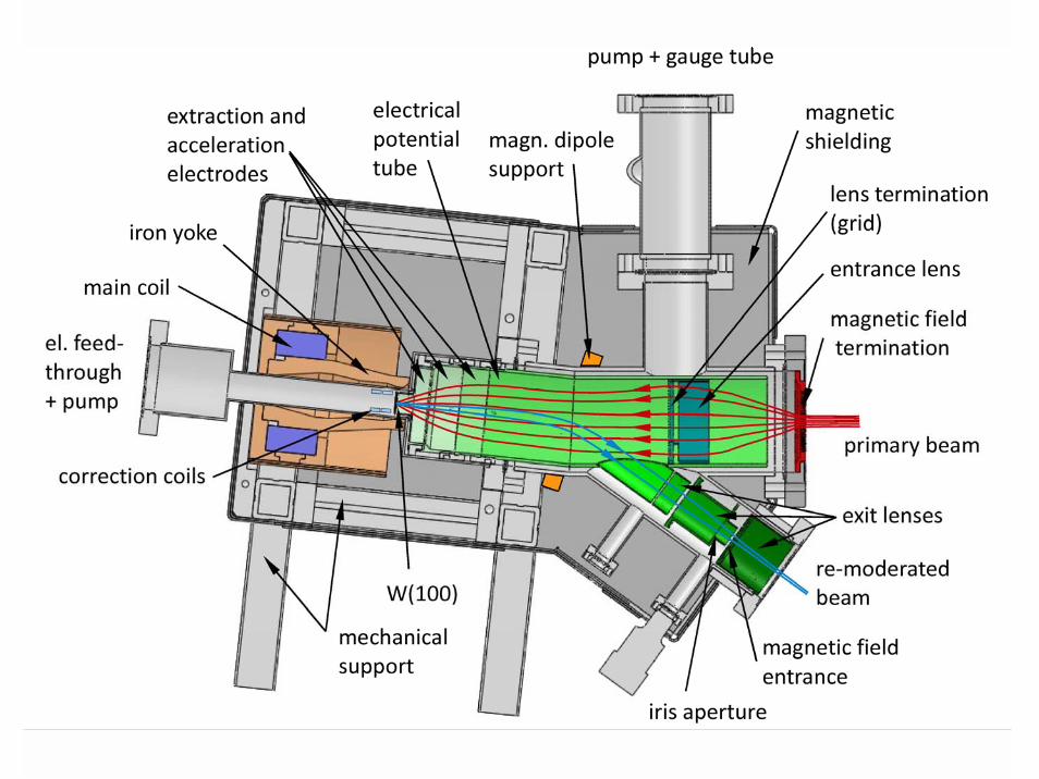
Advanced reflection remoderator
Because of the expected progressat NEPOMUC, the single pole lens is equipped with twoconcentric pole shoes and excitation coils. Withoutdeterioration of sphericalaberrations, the focal length canbe varied between 8 and 16 mm.
For the remoderated positrons, a field lens is included
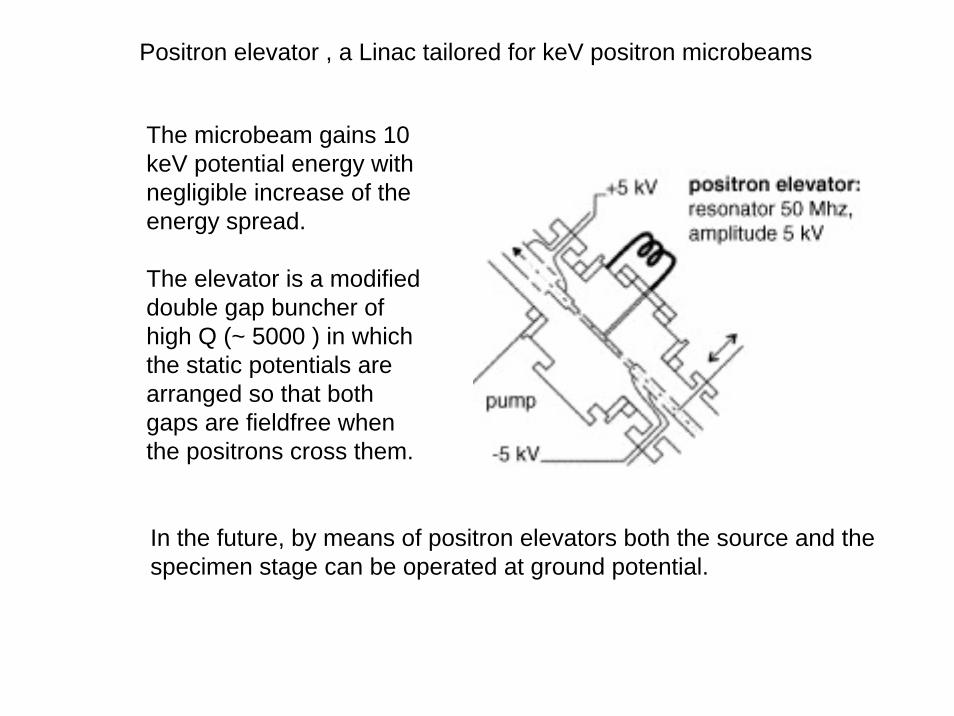
Positron elevator , a Linac tailored for keV positron microbeams
The microbeam gains 10 keV potential energy withnegligible increase of theenergy spread.
The elevator is a modifieddouble gap buncher of high Q (~ 5000 ) in whichthe static potentials arearranged so that bothgaps are fieldfree whenthe positrons cross them.
In the future, by means of positron elevators both the source and thespecimen stage can be operated at ground potential.
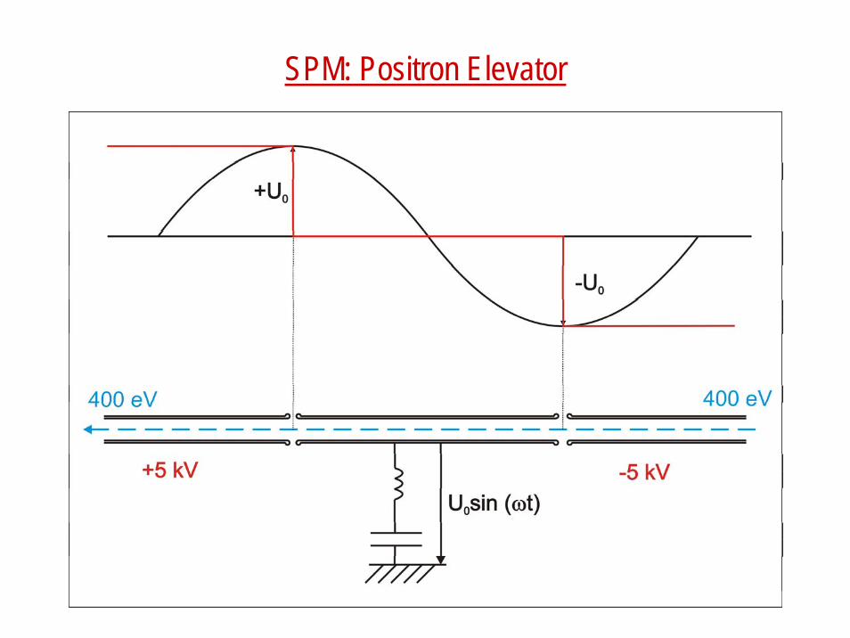
SPM: Positron Elevator
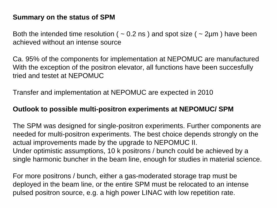
Summary on the status of SPM
Both the intended time resolution ( ~ 0.2 ns ) and spot size ( ~ 2µm ) have beenachieved without an intense source
Ca. 95% of the components for implementation at NEPOMUC are manufacturedWith the exception of the positron elevator, all functions have been succesfullytried and testet at NEPOMUC
Transfer and implementation at NEPOMUC are expected in 2010
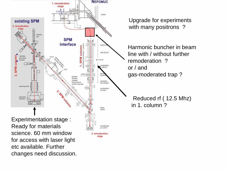
Outlook to possible multi-positron experiments at NEPOMUC/ SPM
The SPM was designed for single-positron experiments. Further components areneeded for multi-positron experiments. The best choice depends strongly on theactual improvements made by the upgrade to NEPOMUC II.Under optimistic assumptions, 10 k positrons / bunch could be achieved by a single harmonic buncher in the beam line, enough for studies in material science.
For more positrons / bunch, either a gas-moderated storage trap must bedeployed in the beam line, or the entire SPM must be relocated to an intensepulsed positron source, e.g. a high power LINAC with low repetition rate.
••
Upgrade for experimentswith many positrons ?
Harmonic buncher in beamline with / without furtherremoderation ?or / andgas-moderated trap ?
Experimentation stage :Ready for materialsscience. 60 mm windowfor access with laser light etc available. Furtherchanges need discussion.
Reduced rf ( 12.5 Mhz) in 1. column ?

Acknowledgement
Over the past two decades about 50 scientists and students havecontributed to the progress of positron beam physics at Munich.
The colleagues mentioned below are also standing for the othercolleagues from the respective groups :
W. Triftshäuser, K.Schreckenbach, R.Brusa
D.Schödlbauer, P.Sperr, A. David, D.T. Britton, K. Uhlmann
W.Egger, Ch.Hugenschmidt, Ch. Piochacz
Funds were provided by (among others ) the European Union, theFederal Republic of Germany, the Free State of Bavaria, theDeutsche Forschungsgemeinschaft and the Universities at Trento , Munich ( TUM) and Neubiberg (UniBwM) .


![OpenResearchOnline - oro.open.ac.uk · SPIS investigations were performed on a slow positron beam SPONSOR [9] with energy of incident positrons adjustable in the range from 0.03 to](https://img.pdfslide.net/doc/110x75/5f4d35c9342b4030c5217864/openresearchonline-oroopenacuk-spis-investigations-were-performed-on-a-slow.jpg)