Embed Size (px)
Citation preview
Technical Guide
Standards and ApprovalsDurapipe UK high performance plastic pipework systems are lightweight and easy to install whilsthaving excellent corrosion and limescale resistance properties.
Durapipe UK products are manufactured to the highest level and meet the requirements of manyinternational standards and approvals.
Furthermore, our products are manufactured in an environment that complies with the requirementsof ISO 9001 and ISO 14001.
Durapipe UK reserves the right to modify the details in this publication as products and specificationsare updated and improved. The content of this publication is for general information only and it is theuser's responsibility to determine the suitability of any product for the purpose intended.
For further information on all Durapipe products and services contact our Customer Services Team on +44 (0)844 800 5509 or fax +44 (0)1543 279450.
Durapipe UK is a trade name of Glynwed Pipe Systems Ltd. Company Number 1698059.
Certificate no. FM34819
Distributor
04900110 February 2013
Registered office:
Durapipe UKWalsall Road Norton CanesCannockStaffordshireWS11 9NSUnited Kingdom Tel: +44 (0)844 800 5509Fax: +44 (0)1543 279450email: [email protected]: www.durapipe.co.uk
PLX TEC
HN
ICA
L GU
IDE
FEBR
UA
RY 2013
email: [email protected] web: www.plxpipe.com 67
1. DEFINITIONS:‘Seller’ shall mean Glynwed Pipe Systems Limited, registered in England under number1698059. ‘Buyer’ shall mean any company, organisation or individual to whom a quotationis offered, or whose order is accepted by the Seller.
2. CONDITIONS:All offers, quotations, estimates, acceptances and contracts are subject to these Conditionsof Business and any terms or conditions which any other person shall seek to impose ormake part of any contract shall, so far as is inconsistent with these Conditions of Business,not apply unless expressly agreed by the Seller in writing. The headings in these conditionsare for convenience only and shall not affect their interpretation.
3. QUOTATIONS AND PRICE VARIATION:a) Any quotation given by the Seller is an invitation to the Buyer to make an offer only andno order of the Buyer placed with the Seller in pursuance of a quotation or otherwise shallbe binding on the Seller unless and until it is accepted in writing by the Seller.
b) Unless stated otherwise, all quotations and published price lists are ex works, exclusiveof VAT and shall remain valid for 30 days or such a period as may be quoted butnevertheless the Seller may amend or withdraw any quotation by written or oral notice.Quotations may be varied if the Buyer makes variations in his specifications.
4. STATEMENTS OR REPRESENTATIONS TO THE BUYER:If any statement or representation has been made to the Buyer upon which the Buyer reliesother than in the documents enclosed with the Seller's quotation, the Buyer must set outthat statement or representation in a document to be attached to or endorsed on the orderin which case the Seller may submit a new quotation.
5. DELIVERY - TIME:a) Any period for delivery given at any time and in any manner by the Seller is an estimateonly and is not binding on the Seller. Delivery periods are normally calculated from the laterof:
i) acceptance of order; or
ii) where applicable, the receipt by the Seller of a detailed specification or drawings.
b) Time shall not be deemed to be of the essence of the contract. Failure by the Seller tomeet any quoted delivery period for any part or the whole of the order shall not entitle theBuyer to rescind the contract or to claim damages of any nature.
c) The Seller will endeavour to comply with reasonable requests by the Buyer forpostponement of delivery but shall be under no obligation to do so. Where delivery ispostponed otherwise than due to default by the Seller the Buyer shall pay all costs andexpenses including a reasonable charge for storage and transportation occasioned therebyand an extra charge for split delivery if applicable.
d) The Buyer will receive delivery of any consignment between the hours of 8.00am and4.00pm Monday to Friday inclusive, unless otherwise agreed in writing. Cost incurred bythe Seller arising from the Buyer's refusal to accept consignments within the agreed hoursshall be borne by the Buyer.
6. DELIVERY AND RISK:a) Except where stated to the contrary in the contract, delivery shall be made as follows:
i) where the Buyer provides the transport, delivery shall be made ex the Seller's works;
ii) where the Seller provides the transport, delivery shall be made to the premises of the Buyer, or the premises of the Buyer's customer or works site if the Buyer has requested delivery to be so made but where the Buyer has made such a request the Seller will make a first delivery to the Buyer's customer or works site as so much of the goods as is available for that delivery but subsequent deliveries will be made to the premises of the Buyer.
b) The Seller may at its discretion make partial delivery of orders and invoice the same.
c) Risk in the goods shall pass on delivery.
d) Where goods are sent FOB the Seller's responsibility shall cease when the goods areplaced on board ship or aircraft without the need for the Seller to give notice to the Buyerand the provisions of Section 32(3) of the Sale of Goods Act 1979 shall not apply.
7. OWNERSHIP OF GOODS:a) The goods shall remain the sole and absolute property of the Seller as legal and equitableowner until such time as the Buyer shall have paid to the Seller the contract price togetherwith the full price of any other goods the subject of any contract between the Seller and theBuyer.
b) The Buyer acknowledges that until such time as the property in the goods passes to theBuyer he is in possession of the goods as a bailee and fiduciary agent for the Seller andthe Purchaser shall store the goods in such a manner that they are clearly identifiable asthe property of the Seller.
c) Until payment due under all contracts between the Buyer and the Seller had been madein full, in the event of sale of the goods by the Buyer:
i) the Seller shall be entitled to trace all proceeds of sale received by the Buyer through any bank or other account maintained by the Buyer; and
ii) the Buyer shall if requested by the Seller in writing to so assign its rights to recover the selling price of the goods from the third parties concerned. Such monies to be held separately by the Buyer as agent on behalf of the Seller.
d) The Seller may for the purpose of recovery of its goods enter upon any premises wherethey are stored or where they are reasonably thought to be stored and may repossess thesame.
8. TERMS OF PAYMENT:In the event of default in payment according to the agreed payment terms between theSeller and the Buyer – ie: by the end of the month following the month of despatch of thegoods the Seller shall be entitled without prejudice to any other right or remedy to suspendall further deliveries and to charge interest on any amount outstanding at the rate of 2% permonth until payment in full is made (a part of a month being treated as a full month for thepurpose of calculating interest).
9. SHORTAGES AND DEFECTS APPARENT ON DELIVERY:a) It shall be the responsibility of the Buyer to inspect or arrange for an inspection of thegoods on delivery whether the goods are delivered to the Buyer's premises or to thepremises of the Buyer's customer or to a works site. If no such inspection is made the Buyershall be deemed to have accepted the goods.
b) The Buyer shall have no claim for shortages or defects apparent on inspection unless:
i) a written complaint is made to the Seller within three days of receipt of the goods specifying the shortage or defect; and
ii) the Seller is within seven days of receipt of the complaint given an opportunity to inspect the goods and investigate the complaint before any use is made of the goods.
c) If a complaint is not made to the Seller as herein provided then in respect of suchshortages or defects the goods shall be deemed to be in all respects in accordance withthe contract and the Buyer shall be bound to pay for the same accordingly.
10. CLAIMS FOR DEFECTS NOT APPARENT ON INSPECTION:a) The Buyer shall have no claim for defects not apparent on inspection unless the Selleris notified of defective workmanship or materials within twelve months from delivery of thegoods. Provided that the goods have been installed and applied in accordance with anyrelevant recommendations made by the Seller, the Seller will at its option replace the goodsor refund the net invoiced price in respect of the goods which have been shown to bedefective. If the Seller does so supply substitute goods the Buyer shall be bound to acceptsuch substituted goods in full satisfaction of the obligations of the Seller under the contract.
b) The Buyer shall in any event have no claim or set-off in respect of defects unless a writtencomplaint is sent to the Seller as soon as the defect is noticed and no use is made of thegoods thereafter or alteration made thereto by the Buyer before the Seller is given anopportunity to inspect the goods.
c) The Buyer is responsible for ensuring that the goods are fit for any particular purpose,and no warranty or condition of fitness for any particular purpose is to be implied into thecontract.
11. LIABILITY:Save as stated in Conditions 9 and 10 (and save in respect of death or personal injuryresulting from the negligence of the Seller its servants or agents) the Seller shall not beliable for any claim or claims for direct or indirect consequential or incidental injury loss ordamage made by the Buyer against the Seller whether in contract or in tort (includingnegligence on the part of the Seller its servants or agents) arising out of or in connectionwith any defect in the goods or their fitness or otherwise for any particular purpose or anyact omission neglect or default of the Seller its servants or agents in the performance of thecontract.
12. FORCE MAJEURE:Notwithstanding anything herein contained neither the Buyer nor the Seller is to be heldliable for any delay or failure to carry out the contract due wholly or in part to an act of Godaction by any Government whether British or foreign civil war strikes and/or lockoutswheresoever occurring fire trade disputes floods or unfavourable weather or any materialbecoming unavailable or irreplaceable (whether at all or at commercially acceptable prices)or any other circumstances beyond the control of the Seller.
13. SUB-CONTRACTING:The Seller reserves the right to sub-contract the fulfilment of any order or any part thereof.
14. INSOLVENCY AND BREACH OF CONTRACT:In the event that:
a) the Buyer commits any breach of the contract and fails to remedy such breach (if capable of remedy) within a period of thirty days from receipt of a notice in writing fromthe Seller requesting such remedy; or
b) any distress or execution is levied upon any of the goods or property of the Buyer; or
c) the Buyer offers to make any arrangements with or for the benefit of its creditors or (if an individual) becomes subject to a petition for a bankruptcy order or (being a limitedcompany) has a receiver appointed of the whole or any part of its undertaking property orassets; or
d) an order is made or a resolution is passed or analogous proceedings are taken for thewinding up of the Buyer (save for the purpose of reconstruction or amalgamation withinsolvency and previously approved in writing by the Seller) the Seller shall thereupon beentitled without prejudice to its other rights hereunder forthwith to suspend all furtherdeliveries until the default has been made good or to determine the contract and anyunfulfilled part thereof or at the Seller's option to make partial deliveries. Notwithstandingany such termination the Buyer shall pay to the Seller at the contract rate for all the goodsdelivered up to and including the date of termination.
15. INDUSTRIAL PROPERTY RIGHTS:If goods supplied by the Seller to the Buyer's design or specifications infringe or are allegedto infringe any patent or registered design right or copyright the Buyer will indemnify theSeller against all damages, costs and expenses incurred by the Seller as a result of theinfringement or allegation. The Buyer will give the Seller all possible help in meeting anyinfringement claim brought against the Seller.
16. BUYER'S ERROR IN ORDERING:In the event the Buyer orders incorrectly the Seller will be under no obligation to the Buyerto rectify or assist in rectifying the error.
17. LAW AND JURISDICTION:The contract shall be subject in all respects to English Law and to the jurisdiction of theEnglish Courts.
DURAPIPE UK CONDITIONS OF SALE
Customer Services Tel: +44 (0)1543 273100 Fax: +44 (0)1543 2794502
Durapipe PLX is a brand from Durapipe UK. Durapipe UK has been at the forefront of thermoplasticpipework technology for over half a century. Our pipes, fittings and valves are widely used in a variety ofindustrial applications around the world.
Manufacturing a wide range of market leading pipework systems for the conveyance of different media,Durapipe systems perform in the most demanding environments.
Durapipe PLX pipework systems have been specially developed for conveying liquid fuels, and are widelyused in service stations, commercial and industrial fuelling applications around the world.
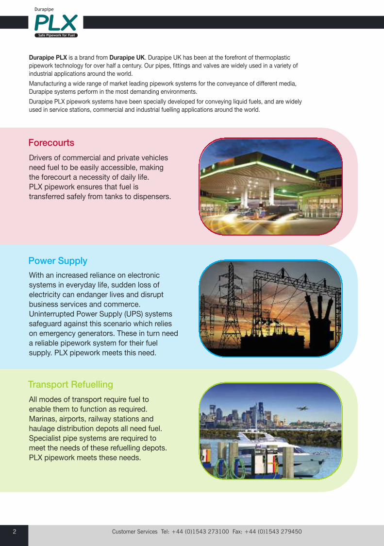
Drivers of commercial and private vehiclesneed fuel to be easily accessible, makingthe forecourt a necessity of daily life. PLX pipework ensures that fuel istransferred safely from tanks to dispensers.
With an increased reliance on electronicsystems in everyday life, sudden loss ofelectricity can endanger lives and disruptbusiness services and commerce.Uninterrupted Power Supply (UPS) systemssafeguard against this scenario which relieson emergency generators. These in turn needa reliable pipework system for their fuelsupply. PLX pipework meets this need.
All modes of transport require fuel toenable them to function as required.Marinas, airports, railway stations andhaulage distribution depots all need fuel.Specialist pipe systems are required tomeet the needs of these refuelling depots. PLX pipework meets these needs.
Forecourts
Power Supply
Transport Refuelling
email: [email protected] web: www.plxpipe.com 3
Durapipe PLX Introduction ..................................................................2
About Durapipe PLX..........................................................................4-5
Materials ................................................................................................6PolyethyleneProtective Barrier Layer
Introduction and Manufacturing Process...........................................7PLX; three systems
Product Specifications .........................................................................8Chemical Resistance of PLXStandard Dimensional Ratio (SDR)Pressure and Flow Ratings
Flow Nomogram....................................................................................9
Electrofusion and Spigot Fittings ................................................10-12Electrofusion PrinciplesBarcode IntroductionTemperature/Fusion Time CompensationSecondary Contained EF#SS FittingsTransition FittingsPipe End Closures and Interstitial Access Points
Durapipe PLX Product Innovations .............................................13-14Close-Fit Unique Transition FittingClose-Fit Extended TransitionsSecondary Containment Electrofusion CouplersIn-Line Anchor FittingsLarge Diameter Tees
Index to PLX Products ..................................................................15-17
Introduction to Application Check...............................................18-19ForecourtsPower SupplyTransport Refuelling
Pipe.................................................................................................20-21Single Wall Pipe .................................................................................20Close-Fit Pipe ....................................................................................21Pipe-In-Pipe .......................................................................................21Hockey-stick Bend.............................................................................21AdBlue® Pipe .....................................................................................21
Electrofusion Fittings ....................................................................22-27Single Wall Primary Coupler...............................................................22Single Wall Primary 45° Elbows .........................................................22Single Wall Primary 90° Elbows .........................................................22Single Wall Primary Equal Tee............................................................23Single Wall Primary Reducer..............................................................23Single Wall Primary End Cap .............................................................23Secondary Contained Coupler with Leads ........................................24Secondary Contained Pipe Joiners ...................................................24Secondary Couplers ..........................................................................24Secondary Contained Reducer (Pipe-In-Pipe)...................................24Secondary Contained Reducer (Close-Fit) ........................................25Secondary Contained 45° Elbows .....................................................25Secondary Contained 90° Elbows .....................................................25Secondary Contained 90° Elbows spigot ..........................................25Secondary Contained Equal Tees ................................................25-26Secondary Contained Reduced Branch Tee......................................26Secondary Contained Slip Closures.............................................26-27Secondary Contained Access Tees ...................................................27Secondary Contained Interstitial Access Saddles.............................27
Page Page
Transition Fittings..........................................................................28-33Single Wall Female electrofusion .......................................................28Single Wall Male electrofusion ..........................................................28Single Wall Female electrofusion compact flange .............................28Single Wall Female spigot ..................................................................28Single Wall Male spigot .....................................................................29Single Wall Female spigot compact flange ........................................29Single Wall Female spigot extended ..................................................29Single Wall Male spigot extended ......................................................29Single Wall Female spigot extended compact flange ........................30Secondary Contained Close-Fit Female spigot extended .................30Secondary Contained Close-Fit Male spigot extended ....................30Secondary Contained Close-Fit spigot extended compact flange ....30Secondary Contained Close-Fit Female electrofusion stainless steel .....................................................................................31Single Wall Stub Flange Assembly spigot .........................................31Secondary Contained In-Line Anchor spigot ....................................31Secondary Contained Drilled Flange Assembly spigot......................32Secondary Contained Female spigot.................................................32Secondary Contained Male spigot ....................................................32Secondary Contained Female spigot compact flange.......................32Secondary Contained 90° Elbow Flanged spigot ..............................32Secondary Contained 90° Elbow Female spigot ..............................33Secondary Contained Reduced Branch Tee Flanged spigot.............33Stage 2 Vapour Recovery Manifold ...................................................33AdBlue® Single Wall Male Extended spigot ......................................33AdBlue® Single Wall Female Extended spigot ..................................33
Accessories ...................................................................................34-35Chamber and Sump Entry Boots.......................................................34Machines............................................................................................34Pipe Preparation Tools .......................................................................35
Leak Detection System by Andel Limited ........................................36
Electrofusion Jointing Introduction ..................................................36
Pipe Preparation Instructions ......................................................37-42Single Wall-Primary Pipe ..............................................................37-38Close-Fit .......................................................................................39-40Pipe-In-Pipe..................................................................................41-42
Single Wall Jointing Guide............................................................43-44
Secondary Containment Jointing Fittings Introduction..................45
Close-Fit Jointing Guide ...............................................................46-48
Pipe-In-Pipe Jointing Guide .........................................................49-51
Installation Guide...........................................................................52-54
Pressure Testing Guide ......................................................................55
Application Specific Installation Overview .................................56-61
General Information............................................................................62
PLX System Warranty.........................................................................63
Durapipe UK Pipework Systems .......................................................64Industrial Building Services
Conditions of Sale...............................................................................67
Contents
Customer Services Tel: +44 (0)1543 273100 Fax: +44 (0)1543 2794504
Durapipe PLX: A high performance multi-layered polyethylene composite pipe system, supplied in single wall andsecondary containment product ranges for various fuelling applications in retail, commercial and industrial markets. Fusion welded for the greatest joint integrity PLX is a specialist range of pipe and fittings specifically designed for thesafe transfer of fuel-based liquids and their vapour in pumped or vacuum applications.
Single Wall – size ranges 32-160mm for below ground applications.
Close-Fit – size ranges 32#40, 50#63, and 63#75mm for below ground applications.
Pipe-In-Pipe – size ranges 32#63, 50#90, 63#110, 90#160,110#160mm for specific above and below ground applications.
PLX offers tremendous advantages over traditional materials;• Single Wall and Secondary Contained systems available• Safe and Durable (30 year design life)• High Performance 10bar primary pipes• Corrosion Resistant• Maintenance Free• Resists permeation• Quick, Clean and Easy Electrofusion Jointing and Installation• Dedicated range of matched fittings• Dimensional stability• Strong and robust• UV Resistant• Full range of accessories and jointing tools• Allows for interstitial monitoring and environmental protection
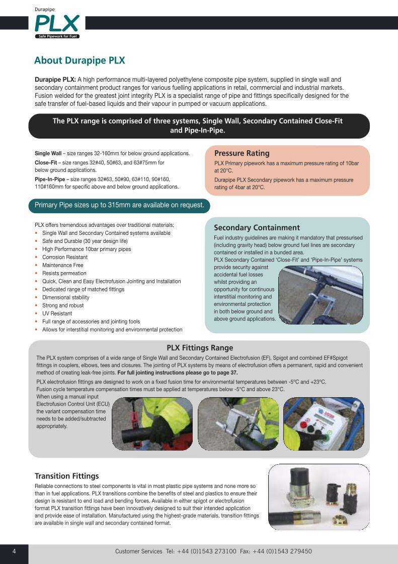
The PLX range is comprised of three systems, Single Wall, Secondary Contained Close-Fit and Pipe-In-Pipe.
Pressure RatingPLX Primary pipework has a maximum pressure rating of 10barat 20°C.
Durapipe PLX Secondary pipework has a maximum pressurerating of 4bar at 20°C.
Secondary ContainmentFuel industry guidelines are making it mandatory that pressurised(including gravity head) below ground fuel lines are secondarycontained or installed in a bunded area. PLX Secondary Contained ‘Close-Fit’ and ‘Pipe-In-Pipe’ systemsprovide security againstaccidental fuel losseswhilst providing anopportunity for continuousinterstitial monitoring andenvironmental protection in both below ground andabove ground applications.
PLX Fittings RangeThe PLX system comprises of a wide range of Single Wall and Secondary Contained Electrofusion (EF), Spigot and combined EF#Spigotfittings in couplers, elbows, tees and closures. The jointing of PLX systems by means of electrofusion offers a permanent, rapid and convenientmethod of creating leak-free joints. For full jointing instructions please go to page 37.
PLX electrofusion fittings are designed to work on a fixed fusion time for environmental temperatures between -5ºC and +23ºC. Fusion cycle temperature compensation times must be applied at temperatures below -5°C and above 23°C. When using a manual inputElectrofusion Control Unit (ECU)the variant compensation timeneeds to be added/subtractedappropriately.
Transition FittingsReliable connections to steel components is vital in most plastic pipe systems and none more sothan in fuel applications. PLX transitions combine the benefits of steel and plastics to ensure theirdesign is resistant to end load and bending forces. Available in either spigot or electrofusionformat PLX transition fittings have been innovatively designed to suit their intended applicationand provide ease of installation. Manufactured using the highest-grade materials, transition fittingsare available in single wall and secondary contained format.
Primary Pipe sizes up to 315mm are available on request.
About Durapipe PLX
Pigmented with Carbon black, PLX secondary contained ‘Pipe-In-Pipe’ systems, have excellent resistance to UV light. Even under the most severeconditions the secondary pipewill retain most of itsmechanical and physicalproperties and will whollyprotect the primary pipe. The pressure rating and 30 year design life isunaffected by exposure to sunlight.
email: [email protected] web: www.plxpipe.com 5
Intr
oduc
tion
Chemical ResistanceDurapipe PLX has a highly visible borethat ensures negligible permeation, lowabsorption and dimensional stabilitywhilst providing excellent chemicalresistance to the Volatile OrganicCompounds (VOCs) of fuels includingpetrol, diesels, fuel oils and biofuels.
PLX systems are suitable for thedistribution of DEF (Diesel Exhaust Fluid)systems such as AdBlue®
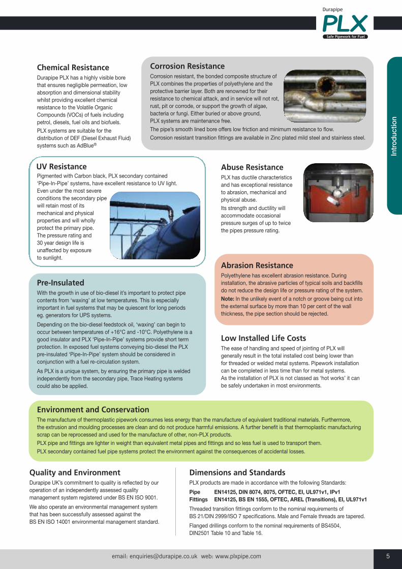
Corrosion Resistance Corrosion resistant, the bonded composite structure of PLX combines the properties of polyethylene and theprotective barrier layer. Both are renowned for theirresistance to chemical attack, and in service will not rot,rust, pit or corrode, or support the growth of algae,bacteria or fungi. Either buried or above ground, PLX systems are maintenance free.
The pipe’s smooth lined bore offers low friction and minimum resistance to flow.
Corrosion resistant transition fittings are available in Zinc plated mild steel and stainless steel.
Pre-InsulatedWith the growth in use of bio-diesel it’s important to protect pipecontents from ‘waxing’ at low temperatures. This is especiallyimportant in fuel systems that may be quiescent for long periods eg. generators for UPS systems.
Depending on the bio-diesel feedstock oil, ‘waxing’ can begin tooccur between temperatures of +16°C and -10°C. Polyethylene is agood insulator and PLX ‘Pipe-In-Pipe’ systems provide short termprotection. In exposed fuel systems conveying bio-diesel the PLXpre-insulated ‘Pipe-In-Pipe’ system should be considered inconjunction with a fuel re-circulation system.
As PLX is a unique system, by ensuring the primary pipe is weldedindependently from the secondary pipe, Trace Heating systemscould also be applied.
Abuse ResistancePLX has ductile characteristicsand has exceptional resistanceto abrasion, mechanical andphysical abuse.
Its strength and ductility willaccommodate occasionalpressure surges of up to twicethe pipes pressure rating.
Abrasion ResistancePolyethylene has excellent abrasion resistance. Duringinstallation, the abrasive particles of typical soils and backfillsdo not reduce the design life or pressure rating of the system.
Note: In the unlikely event of a notch or groove being cut intothe external surface by more than 10 per cent of the wallthickness, the pipe section should be rejected.
Low Installed Life CostsThe ease of handling and speed of jointing of PLX willgenerally result in the total installed cost being lower thanfor threaded or welded metal systems. Pipework installationcan be completed in less time than for metal systems. As the installation of PLX is not classed as ‘hot works’ it canbe safely undertaken in most environments.
Quality and EnvironmentDurapipe UK’s commitment to quality is reflected by ouroperation of an independently assessed qualitymanagement system registered under BS EN ISO 9001.
We also operate an environmental management systemthat has been successfully assessed against the BS EN ISO 14001 environmental management standard.
Dimensions and StandardsPLX products are made in accordance with the following Standards:
Pipe EN14125, DIN 8074, 8075, OFTEC, EI, UL971v1, IPv1Fittings EN14125, BS EN 1555, OFTEC, AREL (Transitions), EI, UL971v1
Threaded transition fittings conform to the nominal requirements of BS 21/DIN 2999/ISO 7 specifications. Male and Female threads are tapered.
Flanged drillings conform to the nominal requirements of BS4504, DIN2501 Table 10 and Table 16.
Environment and ConservationThe manufacture of thermoplastic pipework consumes less energy than the manufacture of equivalent traditional materials. Furthermore, the extrusion and moulding processes are clean and do not produce harmful emissions. A further benefit is that thermoplastic manufacturingscrap can be reprocessed and used for the manufacture of other, non-PLX products.
PLX pipe and fittings are lighter in weight than equivalent metal pipes and fittings and so less fuel is used to transport them.
PLX secondary contained fuel pipe systems protect the environment against the consequences of accidental losses.
UV Resistance
Customer Services Tel: +44 (0)1543 273100 Fax: +44 (0)1543 2794506
PolyethyleneAll products are made from virgin polyethylene.
Polyethylene is a thermoplastic belonging to the material group of polyolefins.
Polyethylene offers numerous features and benefits over traditionalmaterials that include:
Features• Mechanical strength• Chemical resistance• Carbon black properties• Electrofusion jointing
Benefits• Ductile and durable• Does not rot, rust, pit or corrode• UV / weathering resistance• Leak tight assembly
Protective Barrier LayerAll primary pipes are co-extruded and have a lined bore surface. The protective barrier layer has similar mechanical and physicalproperties to polyethylene. Bonding these materials together offersnumerous benefits over unlined pipe:
Features• Smooth bore• Clearly visible bore layer• Chemical resistance
Benefits• Does not support bacteria and algae growth• Minimises frictional head losses • Continuous flow rate• Resists permeation of VOCs
Durapipe PLX pipe and fittings range is a polyethylenebased system with PLX pipe having additional featuresand benefits of a bonded composite structure. PLX hasa protective barrier layer, offering a smooth bore thatensures negligible permeation.
Materials
Polyethylene
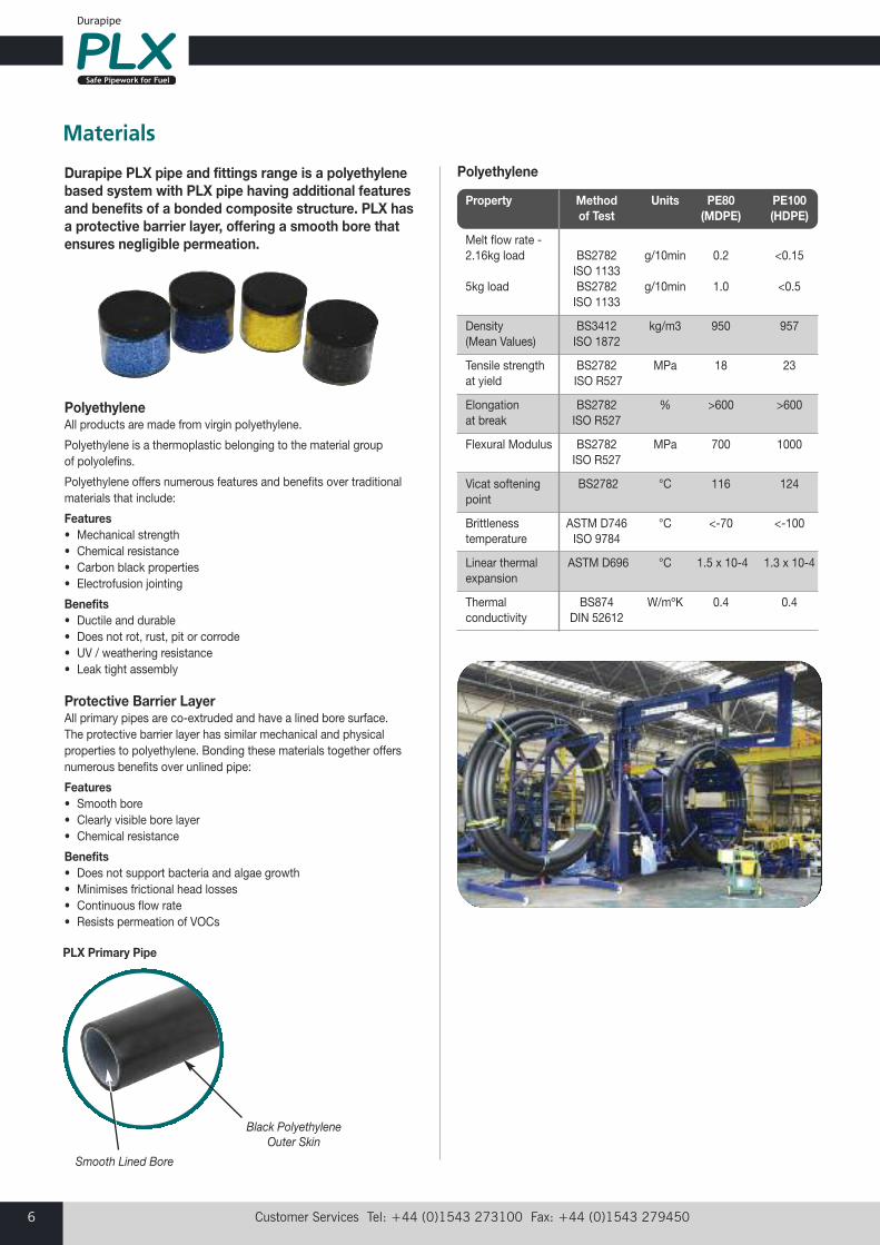
Property Method Units PE80 PE100 of Test (MDPE) (HDPE)
Melt flow rate - 2.16kg load BS2782 g/10min 0.2 <0.15
ISO 1133 5kg load BS2782 g/10min 1.0 <0.5
ISO 1133
Density BS3412 kg/m3 950 957(Mean Values) ISO 1872
Tensile strength BS2782 MPa 18 23at yield ISO R527
Elongation BS2782 % >600 >600at break ISO R527
Flexural Modulus BS2782 MPa 700 1000ISO R527
Vicat softening BS2782 °C 116 124point
Brittleness ASTM D746 °C <-70 <-100temperature ISO 9784
Linear thermal ASTM D696 °C 1.5 x 10⁻⁴ 1.3 x 10⁻⁴ expansion
Thermal BS874 W/mºK 0.4 0.4conductivity DIN 52612
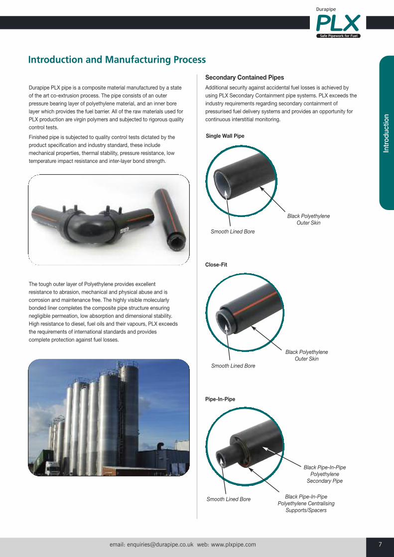
Black PolyethyleneOuter Skin
Smooth Lined Bore
PLX Primary Pipe
email: [email protected] web: www.plxpipe.com 7
Intr
oduc
tion
Black PolyethyleneOuter Skin
Smooth Lined Bore
Durapipe PLX pipe is a composite material manufactured by a stateof the art co-extrusion process. The pipe consists of an outerpressure bearing layer of polyethylene material, and an inner borelayer which provides the fuel barrier. All of the raw materials used forPLX production are virgin polymers and subjected to rigorous qualitycontrol tests.
Finished pipe is subjected to quality control tests dictated by theproduct specification and industry standard, these includemechanical properties, thermal stability, pressure resistance, lowtemperature impact resistance and inter-layer bond strength.
The tough outer layer of Polyethylene provides excellentresistance to abrasion, mechanical and physical abuse and iscorrosion and maintenance free. The highly visible molecularlybonded liner completes the composite pipe structure ensuringnegligible permeation, low absorption and dimensional stability.High resistance to diesel, fuel oils and their vapours, PLX exceedsthe requirements of international standards and providescomplete protection against fuel losses.
Secondary Contained PipesAdditional security against accidental fuel losses is achieved byusing PLX Secondary Containment pipe systems. PLX exceeds theindustry requirements regarding secondary containment ofpressurised fuel delivery systems and provides an opportunity forcontinuous interstitial monitoring.
Introduction and Manufacturing Process
Black PolyethyleneOuter Skin
Smooth Lined Bore
Smooth Lined Bore
Black Pipe-In-PipePolyethylene
Secondary Pipe
Black Pipe-In-PipePolyethylene Centralising
Supports/Spacers
Single Wall Pipe
Close-Fit
Pipe-In-Pipe
Customer Services Tel: +44 (0)1543 273100 Fax: +44 (0)1543 2794508
Chemical Resistance of PLXPetrol and diesel fuels are produced in oil refineries using a distillationprocess. The virgin fuels separated from crude oil during this processdo not, on their own, meet the required specifications for combustionor emissions for modern engines (in particular octane rating) and soare blended with a series of other hydrocarbons Volatile OrganicCompounds (VOCs) and performance additives to create the requiredproperties.
With ever increasing global demands on finite fossil fuel deposits theglobal market is looking for substitutes in the form of biofuelsproduced from a variety of feed stocks and used as a completesubstitute or blended.
The highly visible bonded lining and composite pipe structure ensuresnegligible permeation, low absorption and dimensional stability. PLXhas a high resistance to the following liquid fuels and their vapour:
• Petrol• Diesel• Rapeseed oil• Kerosene• E10 (petrol with 10% ethanol)• E20 (Gasoline with 20% ethanol)• E85 (Gasoline with 85% ethanol)• E100 (Pure ethanol)• B5 (Diesel with up to 5% biodiesel)• B20 (Diesel with up to 20% biodiesel)• B100 (Pure biodiesel)
PLX Single Wall - Used for below ground suctionsystems and available in straight lengths or coils.
PLX Close-Fit - Used for below ground sections ofthe system and available in straight lengths or coils.
PLX Pipe-In-Pipe - Used for specific above andbelow ground fuel transfer applications.
Durapipe PLX Product Specifications
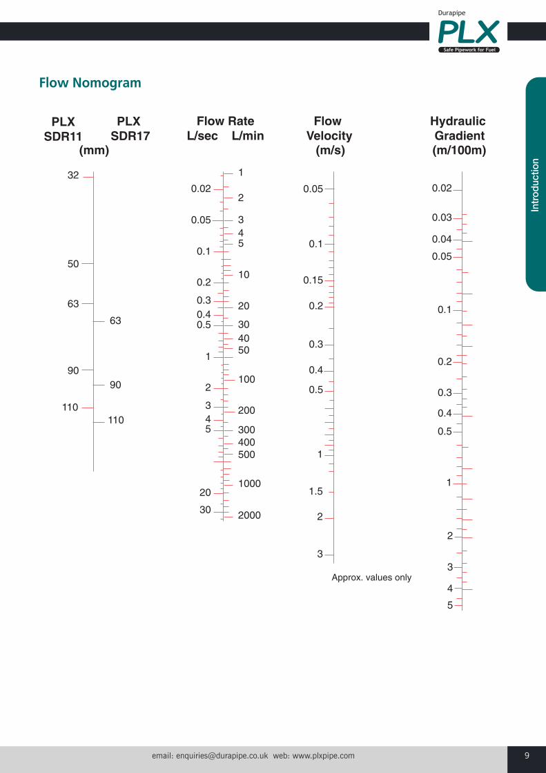
Pressure and Flow RatingsPLX Primary pipe has a maximum pressure rating of 10bar at 20°C.
PLX Secondary pipe has a maximum pressure rating of 4bar at 20°C.
The smooth protective barrier layer of PLX offers a negligible resistanceto flow and will not corrode or support algae growth or deteriorate withuse. PLX will maximise flow rates with greater pump efficiency andminimal operating cost. PLX Fill & Vent (SDR17) improves the fillingtimes of Underground Storage Tanks (USTs) and lessens the chance oftank pressurisation and over filling.
Standard Dimensional Ratio (SDR)One of the items of information contained on both pipe and fittings isthe Standard Dimensional Ratio, ie. the ratio between wall thicknessand outside diameter.
email: [email protected] web: www.plxpipe.com 9
Intr
oduc
tion
0.02
0.05
0.1
0.2
0.3 0.4 0.5
1
2
3 4 5
20
30 2000
1000
500 400 300
200
100
50 40 30
20
10
5 4 3
2
1
0.05
0.1
0.15
0.2
0.3
0.4
0.5
1
1.5
2
3
Approx. values only
0.02
0.03
0.04
0.05
0.1
0.2
0.3
0.4
0.5
1
2
3
4
5
90 90
110
63
110
63
32
50
Hydraulic Gradient
Flow Velocity
Flow RateL/sec L/min
(mm) (m/s) (m/100m)
PLXSDR11
PLX SDR17
Flow Nomogram
Customer Services Tel: +44 (0)1543 273100 Fax: +44 (0)1543 27945010
The PLX system comprises of a wide range of Single Wall andSecondary Contained Spigot and Electrofusion fittings - couplers,elbows, tees and closures. The jointing of PLX pipes throughelectrofusion offers a permanent, rapid and convenient method of pipe joining.
This advanced innovative manufacturing technique of all fittingsensures:
• Deep electrofusion sockets for maximum joint strength on primary pipes
• Gap filling fusion joint process• 39.5V Operation• The heating coils are placed as close to the joint surfaces as possible
• Wire position accurately controlled during manufacture and thefusion process
• Uniform heat distribution during the electrofusion process• Melt pressure and temperature are both accurately controlled• Heating coils are protected from damage during installation• Barcoded containing size and fusion and cooling times• Fusion indicators• Mushroom caps - used after the cooling process for insulating the fusion terminals
All PLX electrofusion fittings employ the same basic principle. The socket of the fitting incorporates an electrical heating coil. An electrofusion control unit (ECU) regulates and supplies the powernecessary to energise and heat the coil. When the coil is energisedthe immediate pipe and fitting surfaces melt to form an expandingpressurised pool of molten material. The continued introduction ofheat energy causes the expanding pool of molten material to mixunder the melt pressure, forming a homogenous mass that is vital inproducing a good weld. Following the termination of the heat cycle,the fitting and pipe are left to cool allowing the melted material tosolidify to form a joint that is stronger than the pipe.
Using PLX EF fittings, consistent, reproducible, high integrity jointswill be achieved if:
• Pipe and fittings preparation instructions are followed (see page 37)
• Pipe and fittings assembly instructions are followed (see page 43)
This will ensure that the installed PLX systems are wholly secure withleak tight joints.
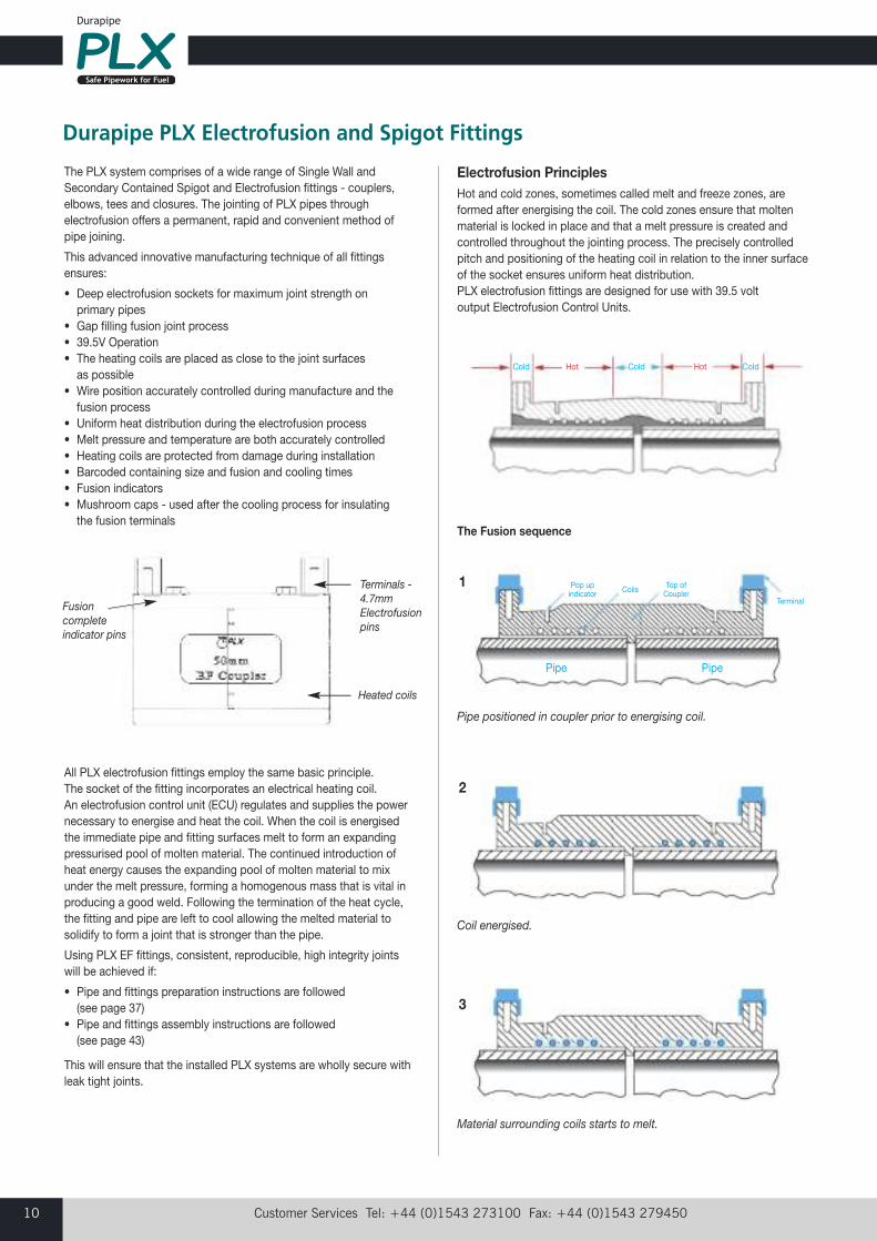
Durapipe PLX Electrofusion and Spigot Fittings
Fusioncompleteindicator pins
Terminals -4.7mmElectrofusionpins
Heated coils
Electrofusion PrinciplesHot and cold zones, sometimes called melt and freeze zones, areformed after energising the coil. The cold zones ensure that moltenmaterial is locked in place and that a melt pressure is created andcontrolled throughout the jointing process. The precisely controlledpitch and positioning of the heating coil in relation to the inner surfaceof the socket ensures uniform heat distribution. PLX electrofusion fittings are designed for use with 39.5 volt output Electrofusion Control Units.
The Fusion sequence
Coil energised.
Pipe positioned in coupler prior to energising coil.
Material surrounding coils starts to melt.
1
2
3
Pipe Pipe
Pop upindicator
Cold Hot HotCold Cold
Top ofCoupler
TerminalCoils
email: [email protected] web: www.plxpipe.com 11
Intr
oduc
tion
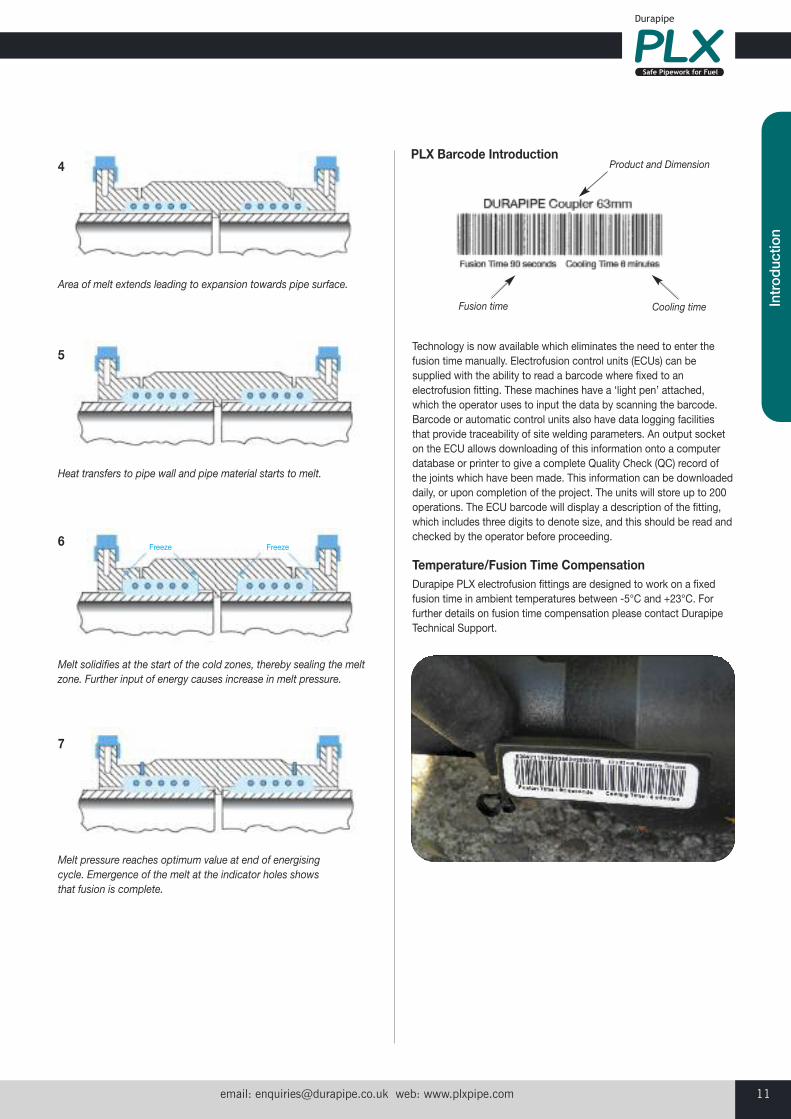
Technology is now available which eliminates the need to enter thefusion time manually. Electrofusion control units (ECUs) can besupplied with the ability to read a barcode where fixed to anelectrofusion fitting. These machines have a ‘light pen’ attached,which the operator uses to input the data by scanning the barcode.Barcode or automatic control units also have data logging facilitiesthat provide traceability of site welding parameters. An output socketon the ECU allows downloading of this information onto a computerdatabase or printer to give a complete Quality Check (QC) record ofthe joints which have been made. This information can be downloadeddaily, or upon completion of the project. The units will store up to 200operations. The ECU barcode will display a description of the fitting,which includes three digits to denote size, and this should be read andchecked by the operator before proceeding.
Temperature/Fusion Time CompensationDurapipe PLX electrofusion fittings are designed to work on a fixedfusion time in ambient temperatures between -5°C and +23°C. Forfurther details on fusion time compensation please contact DurapipeTechnical Support.
Area of melt extends leading to expansion towards pipe surface.
Cooling time
Product and Dimension
Fusion time
4
5
6
7
Heat transfers to pipe wall and pipe material starts to melt.
Melt pressure reaches optimum value at end of energisingcycle. Emergence of the melt at the indicator holes showsthat fusion is complete.
Melt solidifies at the start of the cold zones, thereby sealing the meltzone. Further input of energy causes increase in melt pressure.
Freeze Freeze
PLX Barcode Introduction
Customer Services Tel: +44 (0)1543 273100 Fax: +44 (0)1543 27945012
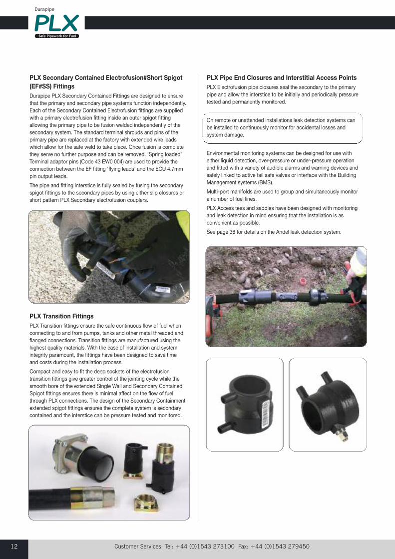
PLX Transition FittingsPLX Transition fittings ensure the safe continuous flow of fuel whenconnecting to and from pumps, tanks and other metal threaded andflanged connections. Transition fittings are manufactured using thehighest quality materials. With the ease of installation and systemintegrity paramount, the fittings have been designed to save time and costs during the installation process.
Compact and easy to fit the deep sockets of the electrofusiontransition fittings give greater control of the jointing cycle while thesmooth bore of the extended Single Wall and Secondary ContainedSpigot fittings ensures there is minimal affect on the flow of fuelthrough PLX connections. The design of the Secondary Containmentextended spigot fittings ensures the complete system is secondarycontained and the interstice can be pressure tested and monitored.
PLX Secondary Contained Electrofusion#Short Spigot(EF#SS) FittingsDurapipe PLX Secondary Contained Fittings are designed to ensurethat the primary and secondary pipe systems function independently.Each of the Secondary Contained Electrofusion fittings are suppliedwith a primary electrofusion fitting inside an outer spigot fittingallowing the primary pipe to be fusion welded independently of thesecondary system. The standard terminal shrouds and pins of theprimary pipe are replaced at the factory with extended wire leadswhich allow for the safe weld to take place. Once fusion is completethey serve no further purpose and can be removed. ‘Spring loaded’Terminal adaptor pins (Code 43 EW0 004) are used to provide theconnection between the EF fitting ‘flying leads’ and the ECU 4.7mmpin output leads.
The pipe and fitting interstice is fully sealed by fusing the secondaryspigot fittings to the secondary pipes by using either slip closures orshort pattern PLX Secondary electrofusion couplers.
PLX Pipe End Closures and Interstitial Access PointsPLX Electrofusion pipe closures seal the secondary to the primarypipe and allow the interstice to be initially and periodically pressuretested and permanently monitored.
On remote or unattended installations leak detection systems canbe installed to continuously monitor for accidental losses andsystem damage.
Environmental monitoring systems can be designed for use witheither liquid detection, over-pressure or under-pressure operationand fitted with a variety of audible alarms and warning devices andsafely linked to active fail safe valves or interface with the BuildingManagement systems (BMS).
Multi-port manifolds are used to group and simultaneously monitora number of fuel lines.
PLX Access tees and saddles have been designed with monitoringand leak detection in mind ensuring that the installation is asconvenient as possible.
See page 36 for details on the Andel leak detection system.
email: [email protected] web: www.plxpipe.com 13
Intr
oduc
tion
The Durapipe PLX product range has developed over the yearsproducing many product innovations that are dedicated to reducingcosts and installation times. These products have been specificallydesigned for fuel related installations and applications.
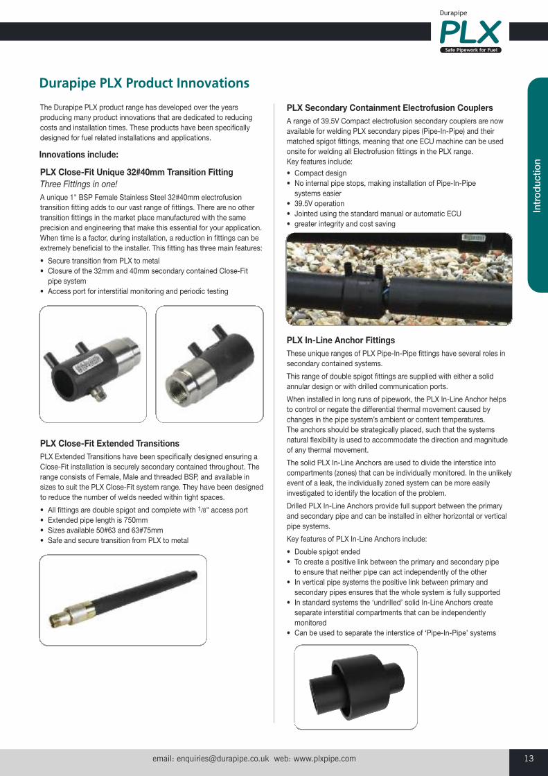
PLX Close-Fit Unique 32#40mm Transition FittingThree Fittings in one!A unique 1" BSP Female Stainless Steel 32#40mm electrofusiontransition fitting adds to our vast range of fittings. There are no othertransition fittings in the market place manufactured with the sameprecision and engineering that make this essential for your application.When time is a factor, during installation, a reduction in fittings can beextremely beneficial to the installer. This fitting has three main features:
• Secure transition from PLX to metal• Closure of the 32mm and 40mm secondary contained Close-Fit pipe system
• Access port for interstitial monitoring and periodic testing
Durapipe PLX Product Innovations
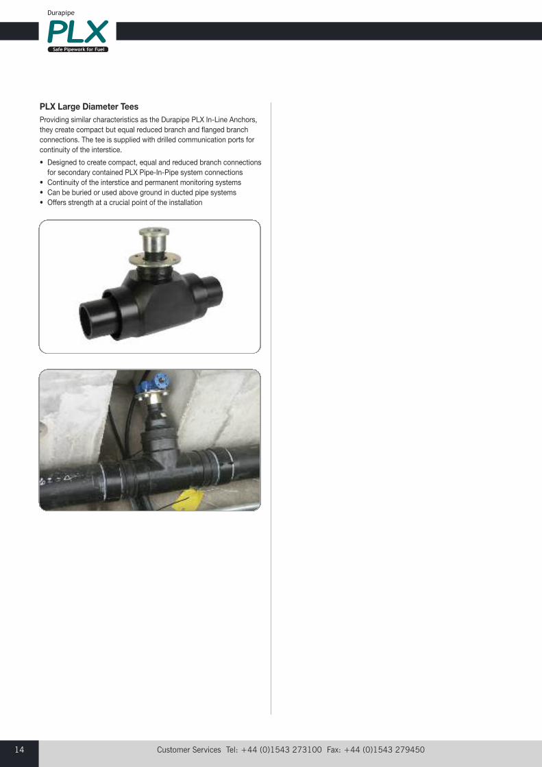
PLX Close-Fit Extended TransitionsPLX Extended Transitions have been specifically designed ensuring a Close-Fit installation is securely secondary contained throughout. Therange consists of Female, Male and threaded BSP, and available insizes to suit the PLX Close-Fit system range. They have been designedto reduce the number of welds needed within tight spaces.
• All fittings are double spigot and complete with 1/8" access port• Extended pipe length is 750mm• Sizes available 50#63 and 63#75mm• Safe and secure transition from PLX to metal
PLX Secondary Containment Electrofusion CouplersA range of 39.5V Compact electrofusion secondary couplers are nowavailable for welding PLX secondary pipes (Pipe-In-Pipe) and theirmatched spigot fittings, meaning that one ECU machine can be usedonsite for welding all Electrofusion fittings in the PLX range. Key features include:
• Compact design • No internal pipe stops, making installation of Pipe-In-Pipesystems easier
• 39.5V operation • Jointed using the standard manual or automatic ECU • greater integrity and cost saving
PLX In-Line Anchor FittingsThese unique ranges of PLX Pipe-In-Pipe fittings have several roles insecondary contained systems.
This range of double spigot fittings are supplied with either a solidannular design or with drilled communication ports.
When installed in long runs of pipework, the PLX In-Line Anchor helpsto control or negate the differential thermal movement caused bychanges in the pipe system’s ambient or content temperatures. The anchors should be strategically placed, such that the systemsnatural flexibility is used to accommodate the direction and magnitudeof any thermal movement.
The solid PLX In-Line Anchors are used to divide the interstice intocompartments (zones) that can be individually monitored. In the unlikelyevent of a leak, the individually zoned system can be more easilyinvestigated to identify the location of the problem.
Drilled PLX In-Line Anchors provide full support between the primaryand secondary pipe and can be installed in either horizontal or verticalpipe systems.
Key features of PLX In-Line Anchors include:
• Double spigot ended • To create a positive link between the primary and secondary pipe to ensure that neither pipe can act independently of the other
• In vertical pipe systems the positive link between primary andsecondary pipes ensures that the whole system is fully supported
• In standard systems the ‘undrilled’ solid In-Line Anchors createseparate interstitial compartments that can be independentlymonitored
• Can be used to separate the interstice of ‘Pipe-In-Pipe’ systems
Innovations include:
Customer Services Tel: +44 (0)1543 273100 Fax: +44 (0)1543 27945014
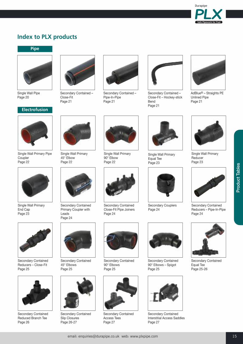
PLX Large Diameter TeesProviding similar characteristics as the Durapipe PLX In-Line Anchors,they create compact but equal reduced branch and flanged branchconnections. The tee is supplied with drilled communication ports forcontinuity of the interstice.
• Designed to create compact, equal and reduced branch connectionsfor secondary contained PLX Pipe-In-Pipe system connections
• Continuity of the interstice and permanent monitoring systems• Can be buried or used above ground in ducted pipe systems• Offers strength at a crucial point of the installation
email: [email protected] web: www.plxpipe.com 15
Pro
duct
Tab
les
Index to PLX products
Single Wall PipePage 20
Secondary Contained –Close-FitPage 21
Secondary Contained –Pipe-In-PipePage 21
Secondary Contained –Close-Fit – Hockey-stickBendPage 21
AdBlue® – Straights PEUnlined PipePage 21
Pipe
Single Wall Primary PipeCouplerPage 22
Single Wall Primary 45° ElbowPage 22
Single Wall Primary 90° ElbowPage 22
Single Wall Primary Equal TeePage 23
Single Wall PrimaryReducerPage 23
Single Wall Primary End CapPage 23
Secondary ContainedPrimary Coupler withLeadsPage 24
Secondary Contained Close-Fit Pipe JoinersPage 24
Secondary CouplersPage 24
Secondary Contained Reducers – Pipe-In-PipePage 24
Secondary ContainedReducers – Close-FitPage 25
Secondary Contained 45° ElbowsPage 25
Secondary Contained 90° ElbowsPage 25
Secondary Contained 90° Elbows – SpigotPage 25
Secondary Contained Equal TeePage 25-26
Secondary Contained Slip ClosuresPage 26-27
Secondary ContainedReduced Branch TeePage 26
Secondary Contained Access TeesPage 27
Secondary Contained Interstitial Access SaddlesPage 27
Electrofusion
Customer Services Tel: +44 (0)1543 273100 Fax: +44 (0)1543 27945016
Index to PLX products
Single Wall EF FemalePage 28
Single Wall EF MalePage 28
Single Wall EF Female –Compact FlangePage 28
Single Wall LS Female –bspPage 28
Single Wall LS Male –bspPage 29
Single Wall LS FemaleCompact Flange – bspPage 29
Single Wall LS FemaleExtended – bspPage 29
Single Wall LS MaleExtended – bspPage 29
Single Wall LS FemaleCompact FlangeExtended – bspPage 30
Secondary Contained –Close-Fit LS FemaleExtended – bspPage 30
Secondary Contained -Close-Fit LS MaleExtendedPage 30
Secondary Contained –Close-Fit CompactFlange ExtendedPage 30
Secondary Contained –Close-Fit Female – bspPage 31
Stub Flange AssemblyPage 31
Secondary Contained In-line AnchorPage 31
Secondary ContainedDrilled Flange AssemblyPage 32
Secondary ContainedFemale – bspPage 32
Secondary ContainedMale – bspPage 32
Secondary ContainedFemale CompactFlange – bspPage 32
Secondary ContainedElbow 90° Flanged (PE)Page 32
Secondary ContainedElbow 90° FemalePage 33
Secondary ContainedReduced BranchFlanged TeePage 33
Stage 2 Vapour RecoveryManifoldPage 33
AdBlue® Single WallMale Extended – bspPage 33
AdBlue® Single WallFemale Extended – bspPage 33
Transitions
email: [email protected] web: www.plxpipe.com 17
Pro
duct
Tab
les
Chamber and SumpEntry BootsPage 34
MachinesPage 34
Pipe Preparation ToolsPage 35
Accessories

Customer Services Tel: +44 (0)1543 273100 Fax: +44 (0)1543 27945018
On pages 20 and 21 there are references to Application Check - APP CHECK. These are there to ensure you are
selecting the correct product for your application needs. Each application is colour coded to make it easier to identify
your product needs. The key to APP CHECK is as follows:
FORECOURT APPLICATION ONLYThese products must only be used in Forecourt applications.
POWER SUPPLY APPLICATION ONLYThese products can be used in Power Supplyapplications.
TRANSPORT REFUELLING APPLICATION ONLYThese products can be used in Transport Refuelling applications.
Introduction to Application Check - APP CHECK
Our Markets
Car, lorry, bus owners need for fuel to be easily accessible,making the forecourt critical to daily life. Ensuring that the fuel is transferred safely, underground from tanks to the pumps forcommercial access, choosing a high performance pipe system is a key element in the process.
Applications• Pressure Systems• Suction Systems• Offset Fill• Vents• Stage 1 and 2 Vapour Recovery• Tank Chamber Connection• Sump & Pump Connection
Durapipe UK has produced fuel pipe systems for this marketfor over 16 years, so have experience of manufacturing highquality product for all applications within this market. PLX was originally designed for the safe transfer of fuel for thismarket and has been installed in thousands of stations aroundthe world during this time.
Products• Single Wall• Secondary Containment Close-Fit• Secondary Containment Pipe-In-Pipe• AdBlue®
Forecourts
FORECOURT & POWER SUPPLYThese products can be used for Forecourt and Power Supply applications.
POWER SUPPLY & TRANSPORT REFUELLINGThese products can be used for Power Supply and Transport Refuelling applications.
ALL APPLICATIONSThese products can be used for all applications.
Case Studies
“The quality and performance of Durapipe PLX products,combined with the service from the technical and support team,has always been exceptional and key to our successfulrelationship. “We initially chose to utilise Durapipe UK as ourpipework supplier for its forward thinking when it comes toproduct development – something thatwe continue to be impressed by.”
Tom Hocking Operations Director at D. Berry and Co. Ltd
“We were particularly impressed with how quick andstraightforward the installation of the pipework was,which is not often something that can besaid about pipework systems. The productwas of the highest quality and as a resultwe are installing it within the six other forecourts we are currently constructing.”
Tuten Aluc Business Development Manager of Interpet, Turkey
email: [email protected] web: www.plxpipe.com 19
Pro
duct
Tab
les
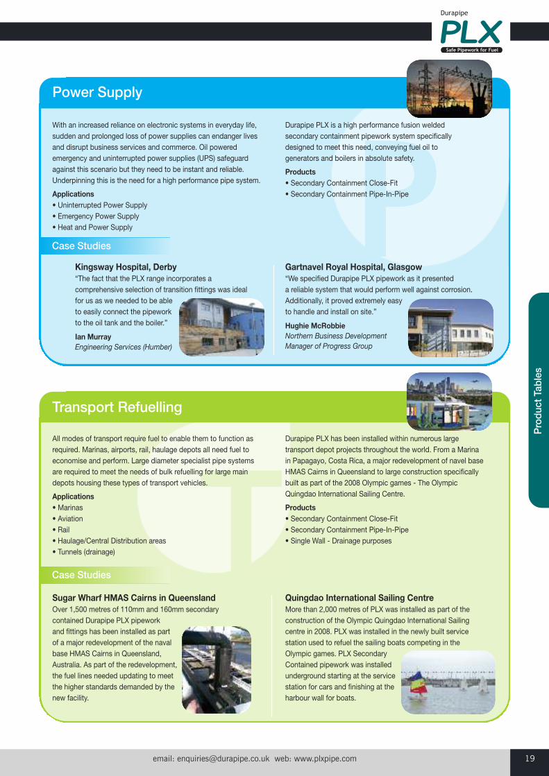
With an increased reliance on electronic systems in everyday life,sudden and prolonged loss of power supplies can endanger livesand disrupt business services and commerce. Oil poweredemergency and uninterrupted power supplies (UPS) safeguardagainst this scenario but they need to be instant and reliable.Underpinning this is the need for a high performance pipe system.
Applications• Uninterrupted Power Supply• Emergency Power Supply• Heat and Power Supply
Durapipe PLX is a high performance fusion weldedsecondary containment pipework system specificallydesigned to meet this need, conveying fuel oil togenerators and boilers in absolute safety.
Products• Secondary Containment Close-Fit• Secondary Containment Pipe-In-Pipe
Power Supply
All modes of transport require fuel to enable them to function asrequired. Marinas, airports, rail, haulage depots all need fuel toeconomise and perform. Large diameter specialist pipe systemsare required to meet the needs of bulk refuelling for large maindepots housing these types of transport vehicles.
Applications• Marinas• Aviation• Rail• Haulage/Central Distribution areas• Tunnels (drainage)
Durapipe PLX has been installed within numerous largetransport depot projects throughout the world. From a Marinain Papagayo, Costa Rica, a major redevelopment of navel baseHMAS Cairns in Queensland to large construction specificallybuilt as part of the 2008 Olympic games - The OlympicQuingdao International Sailing Centre.
Products• Secondary Containment Close-Fit• Secondary Containment Pipe-In-Pipe• Single Wall - Drainage purposes
Transport Refuelling
Kingsway Hospital, Derby“The fact that the PLX range incorporates acomprehensive selection of transition fittings was idealfor us as we needed to be able to easily connect the pipeworkto the oil tank and the boiler.”
Ian Murray Engineering Services (Humber)
Gartnavel Royal Hospital, Glasgow“We specified Durapipe PLX pipework as it presented a reliable system that would perform well against corrosion. Additionally, it proved extremely easyto handle and install on site.”
Hughie McRobbie Northern Business DevelopmentManager of Progress Group
Sugar Wharf HMAS Cairns in QueenslandOver 1,500 metres of 110mm and 160mm secondarycontained Durapipe PLX pipework and fittings has been installed as partof a major redevelopment of the navalbase HMAS Cairns in Queensland,Australia. As part of the redevelopment,the fuel lines needed updating to meetthe higher standards demanded by thenew facility.
Quingdao International Sailing CentreMore than 2,000 metres of PLX was installed as part of theconstruction of the Olympic Quingdao International Sailingcentre in 2008. PLX was installed in the newly built servicestation used to refuel the sailing boats competing in the Olympic games. PLX SecondaryContained pipework was installedunderground starting at the servicestation for cars and finishing at theharbour wall for boats.
Case Studies
Case Studies
Customer Services Tel: +44 (0)1543 273100 Fax: +44 (0)1543 27945020
PLX Pipe Systems
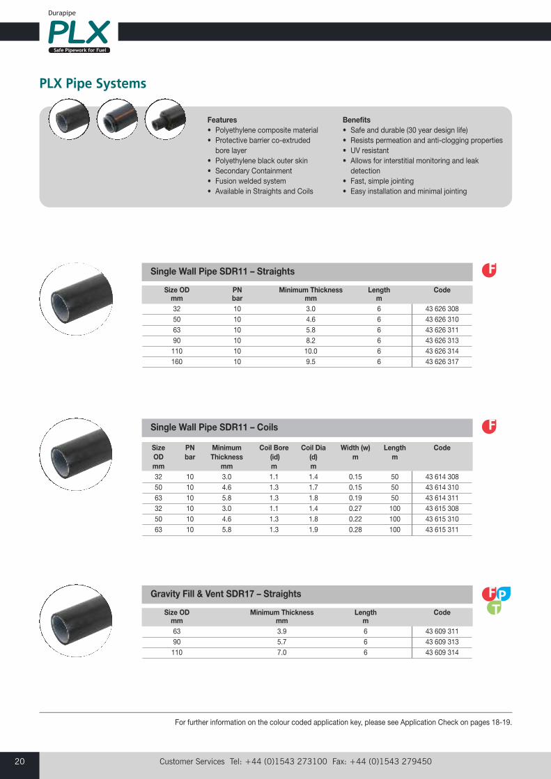
Size PN Minimum Coil Bore Coil Dia Width (w) Length Code OD bar Thickness (id) (d) m m mm mm m m 32 10 3.0 1.1 1.4 0.15 50 43 614 308 50 10 4.6 1.3 1.7 0.15 50 43 614 310 63 10 5.8 1.3 1.8 0.19 50 43 614 311 32 10 3.0 1.1 1.4 0.27 100 43 615 308 50 10 4.6 1.3 1.8 0.22 100 43 615 310 63 10 5.8 1.3 1.9 0.28 100 43 615 311
Single Wall Pipe SDR11 – Coils
Size OD Minimum Thickness Length Code mm mm m 63 3.9 6 43 609 311 90 5.7 6 43 609 313 110 7.0 6 43 609 314
Gravity Fill & Vent SDR17 – Straights
For further information on the colour coded application key, please see Application Check on pages 18-19.
Size OD PN Minimum Thickness Length Code mm bar mm m 32 10 3.0 6 43 626 308 50 10 4.6 6 43 626 310 63 10 5.8 6 43 626 311 90 10 8.2 6 43 626 313 110 10 10.0 6 43 626 314 160 10 9.5 6 43 626 317
Single Wall Pipe SDR11 – Straights
Features• Polyethylene composite material• Protective barrier co-extrudedbore layer
• Polyethylene black outer skin• Secondary Containment• Fusion welded system• Available in Straights and Coils
Benefits• Safe and durable (30 year design life)• Resists permeation and anti-clogging properties• UV resistant• Allows for interstitial monitoring and leakdetection
• Fast, simple jointing• Easy installation and minimal jointing
email: [email protected] web: www.plxpipe.com 21
Pro
duct
Tab
les
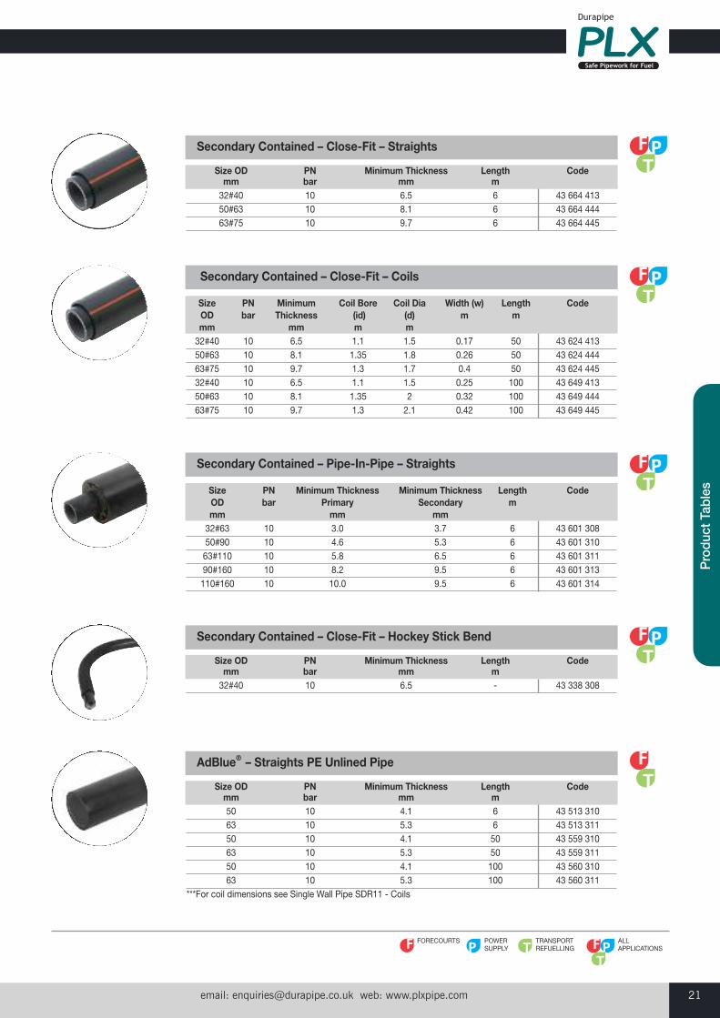
Size OD PN Minimum Thickness Length Code mm bar mm m 32#40 10 6.5 6 43 664 413 50#63 10 8.1 6 43 664 444 63#75 10 9.7 6 43 664 445
Secondary Contained – Close-Fit – Straights
Size OD PN Minimum Thickness Length Code mm bar mm m 32#40 10 6.5 - 43 338 308
Secondary Contained – Close-Fit – Hockey Stick Bend
POWERSUPPLY
TRANSPORTREFUELLING
FORECOURTS ALLAPPLICATIONS
Size OD PN Minimum Thickness Length Code mm bar mm m 50 10 4.1 6 43 513 310 63 10 5.3 6 43 513 311 50 10 4.1 50 43 559 310 63 10 5.3 50 43 559 311 50 10 4.1 100 43 560 310 63 10 5.3 100 43 560 311***For coil dimensions see Single Wall Pipe SDR11 - Coils
AdBlue® – Straights PE Unlined Pipe
Size PN Minimum Coil Bore Coil Dia Width (w) Length Code OD bar Thickness (id) (d) m m mm mm m m 32#40 10 6.5 1.1 1.5 0.17 50 43 624 413 50#63 10 8.1 1.35 1.8 0.26 50 43 624 444 63#75 10 9.7 1.3 1.7 0.4 50 43 624 445 32#40 10 6.5 1.1 1.5 0.25 100 43 649 413 50#63 10 8.1 1.35 2 0.32 100 43 649 444 63#75 10 9.7 1.3 2.1 0.42 100 43 649 445
Secondary Contained – Close-Fit – Coils
Size PN Minimum Thickness Minimum Thickness Length Code OD bar Primary Secondary m mm mm mm 32#63 10 3.0 3.7 6 43 601 308 50#90 10 4.6 5.3 6 43 601 310 63#110 10 5.8 6.5 6 43 601 311 90#160 10 8.2 9.5 6 43 601 313 110#160 10 10.0 9.5 6 43 601 314
Secondary Contained – Pipe-In-Pipe – Straights
Customer Services Tel: +44 (0)1543 273100 Fax: +44 (0)1543 27945022
Size OD PN Description Code mm bar 32 10 39.5V 43 100 308 50 10 39.5V 43 100 310 63 10 39.5V 43 100 311 90 10 39.5V 43 100 313 110 10 39.5V 43 100 314 160 10 39.5V 43 100 317
Single Wall Primary CouplerElectrofusion
Size OD PN Description Code mm bar 32 10 39.5V 43 105 308 50 10 39.5V 43 105 310 63 10 39.5V 43 105 311 90 10 39.5V 43 105 313 110 10 39.5V 43 105 314 160 10 39.5V 43 105 317
Single Wall Primary 45° ElbowElectrofusion
Size OD PN Description Code mm bar 32 10 39.5V 43 104 308 50 10 39.5V 43 104 310 63 10 39.5V 43 104 311 90 10 39.5V 43 104 313 110 10 39.5V 43 104 314 160 10 39.5V 43 104 317
Single Wall Primary 90° ElbowElectrofusion
PLX Electrofusion/Spigot Fittings
Features• Fusion welded system• 39.5V sockets• Secondary Contained fittings• Heating coils are as close to the joint surface as possible
Benefits• Fast, simple jointing• Standard electrofusion voltage• Ensuring welding of Primary independentlyto the Secondary pipe
• Leak tight joints
email: [email protected] web: www.plxpipe.com 23
Pro
duct
Tab
les
Size OD PN Description Code mm bar 32 10 39.5V 43 408 308 50 10 39.5V 43 408 310 63 10 39.5V 43 408 311 90 10 39.5V 43 408 313 110 10 39.5V 43 408 314 160 10 39.5V 43 408 317
Single Wall Primary Equal Tee (Spigot branch)Electrofusion
Size OD PN Description Code mm bar 32 x 50 10 39.5V 43 402 414 32 x 63 10 39.5V 43 402 415 50 x 63 10 39.5V 43 402 444 63 x 90 10 39.5V 43 402 459 90 x 110 10 39.5V 43 402 483 110 x 160 10 39.5V 43 402 495
Single Wall Primary ReducerElectrofusion
Size OD PN Description Code mm bar 32 10 Spigot 43 233 308 50 10 Spigot 43 233 310 63 10 Spigot 43 233 311 90 10 Spigot 43 234 313 110 10 Spigot 43 234 314
Single Wall Primary End CapElectrofusion
Size OD PN Description Code mm bar 90 4 Spigot 43 232 313 110 4 Spigot 43 232 314
Single Wall Primary End Cap – Gravity Fill & VentElectrofusion

Customer Services Tel: +44 (0)1543 273100 Fax: +44 (0)1543 27945024
Size OD PN Description Code mm bar 32 10 39.5V 43 101 308 50 10 39.5V 43 101 310 63 10 39.5V 43 101 311 90 10 39.5V 43 101 313 110 10 39.5V 43 101 314 160 10 39.5V 43 101 317
Secondary Contained Primary Coupler with LeadsElectrofusion
Size OD PN Description Code mm bar 63 10 39.5V 43 110 311 90 10 39.5V 43 110 313 110 10 39.5V 43 110 314 160 10 39.5V 43 110 317For more information on this product please go to page 13.
Secondary CouplersElectrofusion
Size OD PN Description Code mm bar
32#63 x 50#90 10 39.5V 43 342 30850#90 x 63#110 10 39.5V 43 342 31063#110 x 90#160 10 39.5V 43 342 31190#160 x 110#160 10 39.5V 43 342 313
Secondary Contained Reducers – Pipe-In-PipeElectrofusion
Size OD PN Description Code mm bar 32#40 10 39.5V 43 249 308 50#63 10 39.5V 43 249 310 63#75 10 39.5V 43 249 311
Secondary Contained Close-Fit Pipe JoinersElectrofusion
email: [email protected] web: www.plxpipe.com 25
Pro
duct
Tab
les
Size OD PN Description Code mm bar 32#63 10 39.5V with leads 43 250 308 50#90 10 39.5V with leads 43 250 310 63#110 10 39.5V with leads 43 250 311 90#160 10 39.5V with leads 43 250 313 110#160 10 39.5V with leads 43 250 314
Secondary Contained 45° ElbowsElectrofusion#Spigot
Size OD PN Description Code mm bar 32#63 10 39.5V with leads 43 248 308 50#90 10 39.5V with leads 43 248 310 63#110 10 39.5V with leads 43 248 311 90#160 10 39.5V with leads 43 248 313
Secondary Contained 90° ElbowsElectrofusion#Spigot
Size OD PN Description Code mm bar 90#160 10 Double Spigot 43 346 313 110#160 10 Double Spigot 43 346 314
Secondary Contained 90° ElbowsSpigot
Size OD PN Description Code mm bar 32#40 10 39.5V 43 350 308
Secondary Contained Equal TeeElectrofusion
Size OD PN Description Code mm bar 32#40 x 50#63 10 39.5V 43 343 308 50#63 x 63#75 10 39.5V 43 343 310
Secondary Contained Reducers – Close-FitElectrofusion
Customer Services Tel: +44 (0)1543 273100 Fax: +44 (0)1543 27945026
Size OD PN Description Code mm bar 32#90 10 39.5V with leads 43 246 308 50#90 10 39.5V with leads 43 246 310 63#110 10 39.5V with leads 43 246 311
Secondary Contained Equal TeeElectrofusion#Spigot
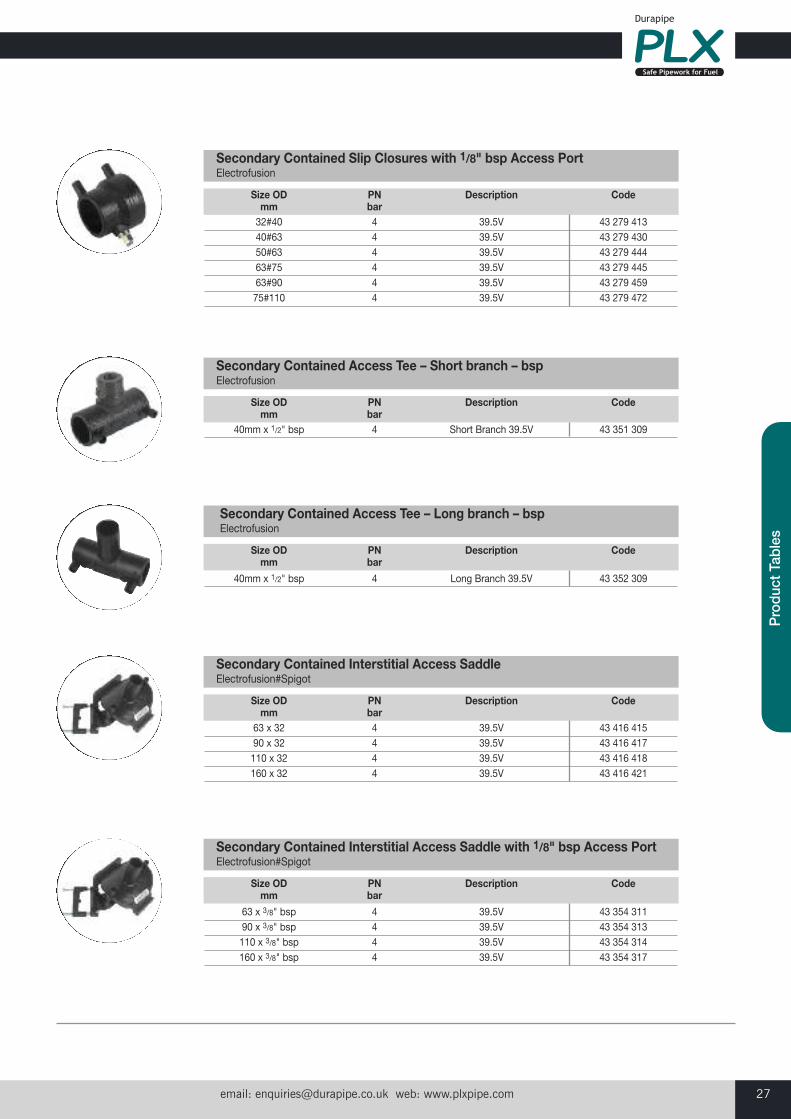
Size OD PN Description Code mm bar 32#40 4 39.5V 43 278 413 40#63 4 39.5V 43 278 430 50#63 4 39.5V 43 278 444 63#75 4 39.5V 43 278 445 63#90 4 39.5V 43 278 459 75#110 4 39.5V 43 278 472
Secondary Contained Slip ClosuresElectrofusion
Size OD PN Description Code mm bar 90#160 10 Double Spigot 43 348 313 110#160 10 Double Spigot 43 348 314
Secondary Contained Equal TeeDouble Spigot
Size OD PN Description Code mm bar 90#160#63#110 10 Double Spigot 43 349 313 110#160#63#110 10 Double Spigot 43 349 314
Secondary Contained Reduced Branch TeeDouble Spigot
email: [email protected] web: www.plxpipe.com 27
Pro
duct
Tab
les
Size OD PN Description Code mm bar 32#40 4 39.5V 43 279 413 40#63 4 39.5V 43 279 430 50#63 4 39.5V 43 279 444 63#75 4 39.5V 43 279 445 63#90 4 39.5V 43 279 459 75#110 4 39.5V 43 279 472
Secondary Contained Slip Closures with 1/8" bsp Access PortElectrofusion
Size OD PN Description Code mm bar 40mm x 1/2" bsp 4 Short Branch 39.5V 43 351 309
Secondary Contained Access Tee – Short branch – bspElectrofusion
Size OD PN Description Code mm bar
40mm x 1/2" bsp 4 Long Branch 39.5V 43 352 309
Secondary Contained Access Tee – Long branch – bspElectrofusion
Size OD PN Description Code mm bar 63 x 32 4 39.5V 43 416 415 90 x 32 4 39.5V 43 416 417 110 x 32 4 39.5V 43 416 418 160 x 32 4 39.5V 43 416 421
Secondary Contained Interstitial Access SaddleElectrofusion#Spigot
Size OD PN Description Code mm bar
63 x 3/8" bsp 4 39.5V 43 354 311 90 x 3/8" bsp 4 39.5V 43 354 313 110 x 3/8" bsp 4 39.5V 43 354 314 160 x 3/8" bsp 4 39.5V 43 354 317
Secondary Contained Interstitial Access Saddle with 1/8" bsp Access PortElectrofusion#Spigot
Customer Services Tel: +44 (0)1543 273100 Fax: +44 (0)1543 27945028
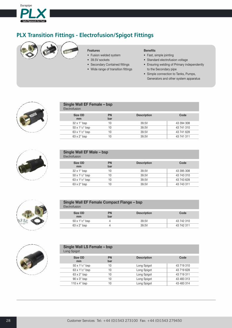
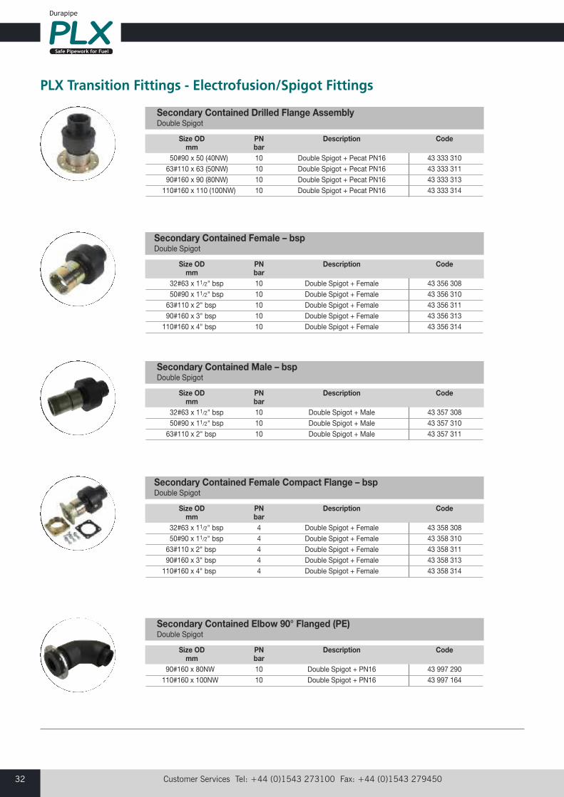
PLX Transition Fittings - Electrofusion/Spigot Fittings
Features• Fusion welded system• 39.5V sockets• Secondary Contained fittings• Wide range of transition fittings
Benefits• Fast, simple jointing• Standard electrofusion voltage• Ensuring welding of Primary independentlyto the Secondary pipe
• Simple connection to Tanks, Pumps,Generators and other system apparatus
Size OD PN Description Code mm bar 32 x 1" bsp 10 39.5V 43 394 308 50 x 11/2" bsp 10 39.5V 43 741 310 63 x 11/2" bsp 10 39.5V 43 741 628 63 x 2" bsp 10 39.5V 43 741 311
Single Wall EF Female – bspElectrofusion
Size OD PN Description Code mm bar 32 x 1" bsp 10 39.5V 43 395 308 50 x 11/2" bsp 10 39.5V 43 743 310 63 x 11/2" bsp 10 39.5V 43 743 628 63 x 2" bsp 10 39.5V 43 743 311
Single Wall EF Male – bspElectrofusion
Size OD PN Description Code mm bar 50 x 11/2" bsp 4 39.5V 43 742 310 63 x 2" bsp 4 39.5V 43 742 311
Single Wall EF Female Compact Flange – bspElectrofusion
Size OD PN Description Code mm bar
50 x 11/2" bsp 10 Long Spigot 43 719 31063 x 11/2" bsp 10 Long Spigot 43 719 62863 x 2" bsp 10 Long Spigot 43 719 31190 x 3" bsp 10 Long Spigot 43 483 313110 x 4" bsp 10 Long Spigot 43 483 314
Single Wall LS Female – bspLong Spigot
email: [email protected] web: www.plxpipe.com 29
Pro
duct
Tab
les
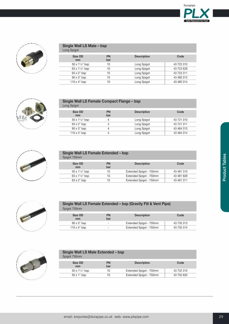
Size OD PN Description Code mm bar
50 x 11/2" bsp 10 Long Spigot 43 723 31063 x 11/2" bsp 10 Long Spigot 43 723 62863 x 2" bsp 10 Long Spigot 43 723 31190 x 3" bsp 10 Long Spigot 43 480 313110 x 4" bsp 10 Long Spigot 43 480 314
Single Wall LS Male – bspLong Spigot
Size OD PN Description Code mm bar
50 x 11/2" bsp 4 Long Spigot 43 721 31063 x 2" bsp 4 Long Spigot 43 721 31190 x 3" bsp 4 Long Spigot 43 484 313110 x 4" bsp 4 Long Spigot 43 484 314
Single Wall LS Female Compact Flange – bspLong Spigot
Size OD PN Description Code mm bar
50 x 11/2" bsp 10 Extended Spigot - 750mm 43 481 31063 x 11/2" bsp 10 Extended Spigot - 750mm 43 481 62863 x 2" bsp 10 Extended Spigot - 750mm 43 481 311
Single Wall LS Female Extended – bspSpigot 750mm
Size OD PN Description Code mm bar
90 x 3" bsp - Extended Spigot - 750mm 43 735 313110 x 4" bsp - Extended Spigot - 750mm 43 735 314
Single Wall LS Female Extended – bsp (Gravity Fill & Vent Pipe)Spigot 750mm
Size OD PN Description Code mm bar
50 x 11/2" bsp 10 Extended Spigot - 750mm 43 752 31050 x 1" bsp 10 Extended Spigot - 750mm 43 752 620
Single Wall LS Male Extended – bspSpigot 750mm
Customer Services Tel: +44 (0)1543 273100 Fax: +44 (0)1543 27945030
Size OD PN Description Code mm bar
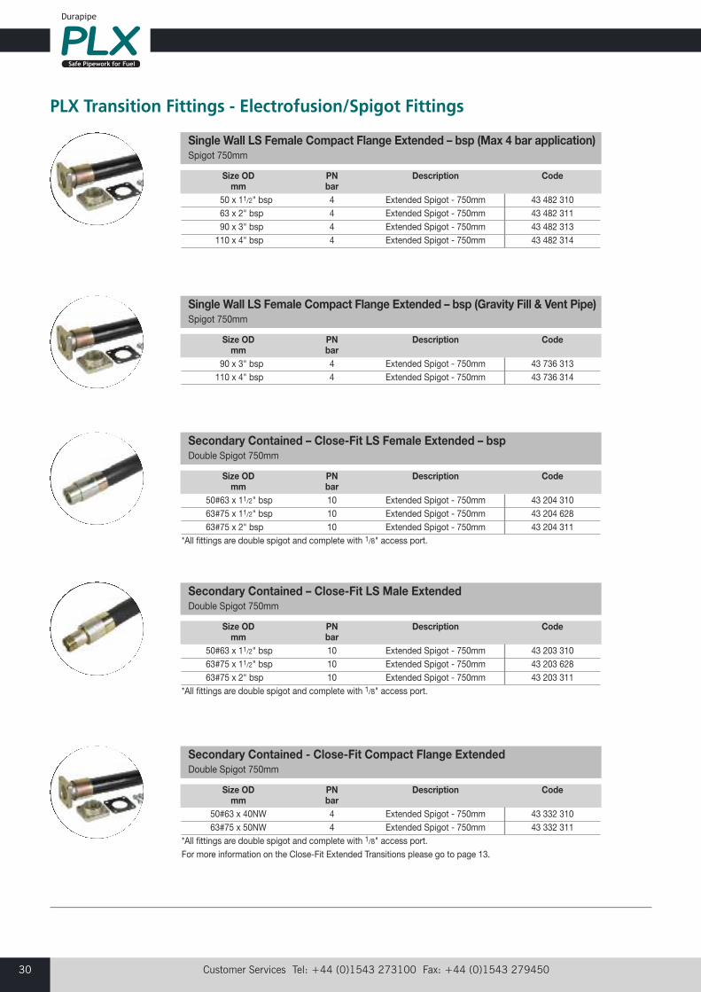
50 x 11/2" bsp 4 Extended Spigot - 750mm 43 482 31063 x 2" bsp 4 Extended Spigot - 750mm 43 482 31190 x 3" bsp 4 Extended Spigot - 750mm 43 482 313110 x 4" bsp 4 Extended Spigot - 750mm 43 482 314
Single Wall LS Female Compact Flange Extended – bsp (Max 4 bar application)Spigot 750mm
Size OD PN Description Code mm bar
90 x 3" bsp 4 Extended Spigot - 750mm 43 736 313110 x 4" bsp 4 Extended Spigot - 750mm 43 736 314
Single Wall LS Female Compact Flange Extended – bsp (Gravity Fill & Vent Pipe)Spigot 750mm
Size OD PN Description Code mm bar
50#63 x 11/2" bsp 10 Extended Spigot - 750mm 43 204 31063#75 x 11/2" bsp 10 Extended Spigot - 750mm 43 204 62863#75 x 2" bsp 10 Extended Spigot - 750mm 43 204 311
*All fittings are double spigot and complete with 1/8" access port.
Secondary Contained – Close-Fit LS Female Extended – bspDouble Spigot 750mm
Size OD PN Description Code mm bar
50#63 x 11/2" bsp 10 Extended Spigot - 750mm 43 203 31063#75 x 11/2" bsp 10 Extended Spigot - 750mm 43 203 62863#75 x 2" bsp 10 Extended Spigot - 750mm 43 203 311
*All fittings are double spigot and complete with 1/8" access port.
Secondary Contained – Close-Fit LS Male ExtendedDouble Spigot 750mm
Size OD PN Description Code mm bar 50#63 x 40NW 4 Extended Spigot - 750mm 43 332 310 63#75 x 50NW 4 Extended Spigot - 750mm 43 332 311*All fittings are double spigot and complete with 1/8" access port.For more information on the Close-Fit Extended Transitions please go to page 13.
Secondary Contained - Close-Fit Compact Flange ExtendedDouble Spigot 750mm
PLX Transition Fittings - Electrofusion/Spigot Fittings
email: [email protected] web: www.plxpipe.com 31
Pro
duct
Tab
les
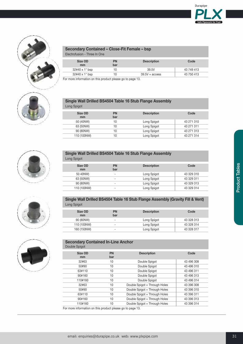
Size OD PN Description Code mm bar 50 (40NW) 10 Long Spigot 43 271 310 63 (50NW) 10 Long Spigot 43 271 311 90 (80NW) 10 Long Spigot 43 271 313 110 (100NW) 10 Long Spigot 43 271 314
Single Wall Drilled BS4504 Table 16 Stub Flange Assembly Long Spigot
Size OD PN Description Code mm bar 50 40NW) - Long Spigot 43 329 310 63 (50NW) - Long Spigot 43 329 311 90 (80NW) - Long Spigot 43 329 313 110 (100NW) - Long Spigot 43 329 314
Single Wall Drilled BS4504 Table 16 Stub Flange AssemblyLong Spigot
Size OD PN Description Code mm bar 90 (80NW) - Long Spigot 43 328 313 110 (100NW) - Long Spigot 43 328 314 160 (150NW) - Long Spigot 43 328 317
Single Wall Drilled BS4504 Table 16 Stub Flange Assembly (Gravity Fill & Vent)Long Spigot
Size OD PN Description Code mm bar 32#40 x 1" bsp 10 39.5V 43 749 413 32#40 x 1" bsp 10 39.5V + access 43 750 413For more information on this product please go to page 13.
Secondary Contained – Close-Fit Female – bspElectrofusion - Three In One
Size OD PN Description Code mm bar 32#63 10 Double Spigot 43 496 308 50#90 10 Double Spigot 43 496 310 63#110 10 Double Spigot 43 496 311 90#160 10 Double Spigot 43 496 313 110#160 10 Double Spigot 43 496 314 32#63 10 Double Spigot + Through Holes 43 396 308 50#90 10 Double Spigot + Through Holes 43 396 310 63#110 10 Double Spigot + Through Holes 43 396 311 90#160 10 Double Spigot + Through Holes 43 396 313 110#160 10 Double Spigot + Through Holes 43 396 314For more information on this product please go to page 13.
Secondary Contained In-Line AnchorDouble Spigot
Customer Services Tel: +44 (0)1543 273100 Fax: +44 (0)1543 27945032
PLX Transition Fittings - Electrofusion/Spigot Fittings
Size OD PN Description Code mm bar
50#90 x 50 (40NW) 10 Double Spigot + Pecat PN16 43 333 31063#110 x 63 (50NW) 10 Double Spigot + Pecat PN16 43 333 31190#160 x 90 (80NW) 10 Double Spigot + Pecat PN16 43 333 313110#160 x 110 (100NW) 10 Double Spigot + Pecat PN16 43 333 314
Secondary Contained Drilled Flange AssemblyDouble Spigot
Size OD PN Description Code mm bar
32#63 x 11/2" bsp 10 Double Spigot + Female 43 356 30850#90 x 11/2" bsp 10 Double Spigot + Female 43 356 31063#110 x 2" bsp 10 Double Spigot + Female 43 356 31190#160 x 3" bsp 10 Double Spigot + Female 43 356 313110#160 x 4" bsp 10 Double Spigot + Female 43 356 314
Secondary Contained Female – bspDouble Spigot
Size OD PN Description Code mm bar
32#63 x 11/2" bsp 4 Double Spigot + Female 43 358 30850#90 x 11/2" bsp 4 Double Spigot + Female 43 358 31063#110 x 2" bsp 4 Double Spigot + Female 43 358 31190#160 x 3" bsp 4 Double Spigot + Female 43 358 313110#160 x 4" bsp 4 Double Spigot + Female 43 358 314
Secondary Contained Female Compact Flange – bspDouble Spigot
Size OD PN Description Code mm bar
90#160 x 80NW 10 Double Spigot + PN16 43 997 290110#160 x 100NW 10 Double Spigot + PN16 43 997 164
Secondary Contained Elbow 90° Flanged (PE)Double Spigot
Size OD PN Description Code mm bar
32#63 x 11/2" bsp 10 Double Spigot + Male 43 357 30850#90 x 11/2" bsp 10 Double Spigot + Male 43 357 31063#110 x 2" bsp 10 Double Spigot + Male 43 357 311
Secondary Contained Male – bspDouble Spigot
email: [email protected] web: www.plxpipe.com 33
Pro
duct
Tab
les
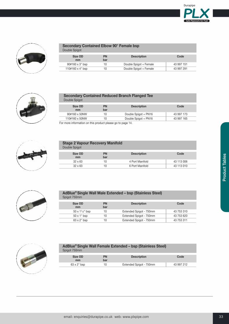
Size OD PN Description Code mm bar
90#160 x 3" bsp 10 Double Spigot + Female 43 997 151110#160 x 4" bsp 10 Double Spigot + Female 43 997 291
Secondary Contained Elbow 90° Female bspDouble Spigot
Size OD PN Description Code mm bar
90#160 x 50NW 10 Double Spigot + PN16 43 997 173110#160 x 50NW 10 Double Spigot + PN16 43 997 165
For more information on this product please go to page 14.
Secondary Contained Reduced Branch Flanged TeeDouble Spigot
Size OD PN Description Code mm bar 32 x 63 10 4 Port Manifold 43 113 006 32 x 63 10 6 Port Manifold 43 113 010
Stage 2 Vapour Recovery ManifoldDouble Spigot
Size OD PN Description Code mm bar
50 x 11/2" bsp 10 Extended Spigot - 750mm 43 753 31050 x 1" bsp 10 Extended Spigot - 750mm 43 753 62063 x 2" bsp 10 Extended Spigot - 750mm 43 753 311
AdBlue®Single Wall Male Extended – bsp (Stainless Steel)Spigot 750mm
Size OD PN Description Code mm bar 63 x 2" bsp 10 Extended Spigot - 750mm 43 997 212
AdBlue® Single Wall Female Extended – bsp (Stainless Steel)Spigot 750mm
Customer Services Tel: +44 (0)1543 273100 Fax: +44 (0)1543 27945034
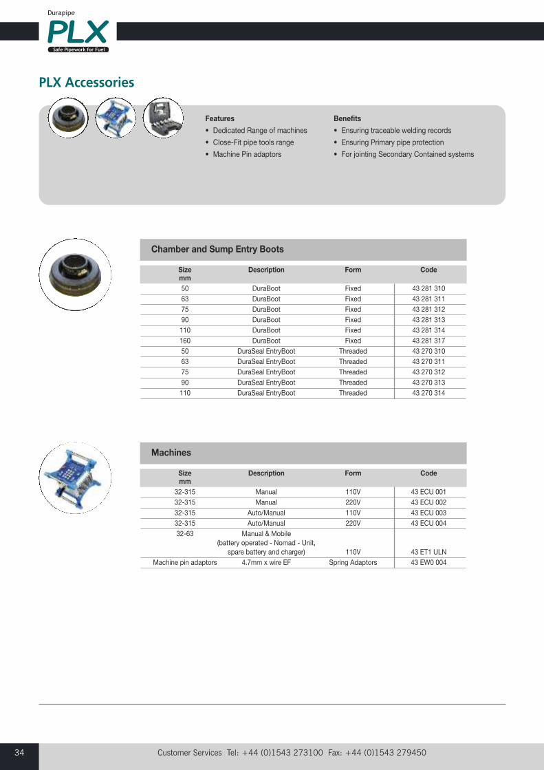
PLX Accessories
Features
• Dedicated Range of machines
• Close-Fit pipe tools range
• Machine Pin adaptors
Benefits
• Ensuring traceable welding records
• Ensuring Primary pipe protection
• For jointing Secondary Contained systems
Size Description Form Code mm 50 DuraBoot Fixed 43 281 310 63 DuraBoot Fixed 43 281 311 75 DuraBoot Fixed 43 281 312 90 DuraBoot Fixed 43 281 313 110 DuraBoot Fixed 43 281 314 160 DuraBoot Fixed 43 281 317 50 DuraSeal EntryBoot Threaded 43 270 310 63 DuraSeal EntryBoot Threaded 43 270 311 75 DuraSeal EntryBoot Threaded 43 270 312 90 DuraSeal EntryBoot Threaded 43 270 313 110 DuraSeal EntryBoot Threaded 43 270 314
Chamber and Sump Entry Boots
Size Description Form Code mm 32-315 Manual 110V 43 ECU 001 32-315 Manual 220V 43 ECU 002 32-315 Auto/Manual 110V 43 ECU 003 32-315 Auto/Manual 220V 43 ECU 004 32-63 Manual & Mobile (battery operated - Nomad - Unit, spare battery and charger) 110V 43 ET1 ULN Machine pin adaptors 4.7mm x wire EF Spring Adaptors 43 EW0 004
Machines
email: [email protected] web: www.plxpipe.com 35
Pro
duct
Tab
les
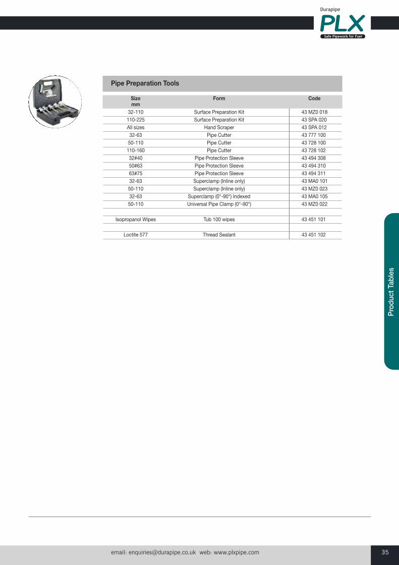
Size Form Code mm 32-110 Surface Preparation Kit 43 MZ0 018 110-225 Surface Preparation Kit 43 SPA 020 All sizes Hand Scraper 43 SPA 012 32-63 Pipe Cutter 43 777 100 50-110 Pipe Cutter 43 728 100 110-160 Pipe Cutter 43 728 102 32#40 Pipe Protection Sleeve 43 494 308 50#63 Pipe Protection Sleeve 43 494 310 63#75 Pipe Protection Sleeve 43 494 311 32-63 Superclamp (Inline only) 43 MA0 101 50-110 Superclamp (Inline only) 43 MZ0 023 32-63 Superclamp (0°-90°) Indexed 43 MA0 105 50-110 Universal Pipe Clamp (0°-90°) 43 MZ0 022 Isopropanol Wipes Tub 100 wipes 43 451 101 Loctite 577 Thread Sealant 43 451 102
Pipe Preparation Tools
Customer Services Tel: +44 (0)1543 273100 Fax: +44 (0)1543 27945036
Durapipe PLX pipes and fittings are jointed by Electrofusion welding.Electrofusion is a simple, quick and easy method of jointing plasticpipe systems producing high integrity, permanent joints. Electrofusionhas been an approved method of jointing polyethylene systems in theinternational gas and water industry for many years.
Prior to jointing, the outer surface of the PLX pipe or PLX spigot fittingmust be removed.
Pipe surfaces can be prepared using a PLX Pipe Preparation tool. The PLX Multi-pipe Preparation Kit (PLX product code 43 MZ0 018 (32-110mm) or 43 SPA 020 (110-225mm), is designed to mountconcentric to the pipe and respective to pipe size and classinterchangeable expanding mandrels and sleeves ensure the tool isheld firmly in place during the peeling operation. Rotating about thepipe axis the spring loaded HSS cutter tip ensures, regardless ofoperator that an even amount of material is removed.
PLX spigot fittings must be scraped manually using a PLX hand scraper.
Abrading the pipe end or fitting end prior to fusion is not effective inremoving the outer surface. Years of experience has shown that toachieve maximum joint strength it is essential that the pipe surfacesare scraped or peeled.
Prepared pipe surfaces should always be kept clean and pipepreparation should always take place immediately prior to fusionwelding. If this is not possible, the prepared surface of the pipe mustbe covered to protect it from contamination.
If left for a period of time or dirtied both joint surfaces must be cleaned with an Isopropanol wipe before welding (PLX product code43 451 100).
Each electrofusion fitting is sealed in a bag at the point of manufactureto protect the surfaces against contamination and damage. Do notopen the bag until required.
Electrofusion fittings must not be scraped.
Electrofusion Jointing
CAUTION• DO NOT allow water to penetrate the joint priorto or during fusion welding
• DO NOT assemble or begin fusion PLX systemsif either pipe ends or fitting are contaminatedwith any deleterious material
• DO NOT use near naked flames
• DO NOT smoke in the working area
• DO NOT joint in rainy conditions unless a shelteris provided to keep surfaces dry
Durapipe Leak Detection System by Andel LimitedDurapipe recommend a leak detection system from Andel Limited.Andel Limited was formed in 1992 and with a commitment toservice, product development and quality, has a proven trackrecord as the market leader in leak detection systems.
The sensor uses infrared to detect the presence of any liquidtouching the sensor dome. When liquid is detected, the relay withinthe local control unit will turn off, and therefore be detected by amonitoring system. The relay will also turn off if the sensor shouldbecome disconnected or if the power should fail.
The Andel Pipe-in-Pipe leak detection system is designed forapplications where a stand-alone leak detection system is required.The system consists of two components, the sensor head and localcontrol box. The sensor head is a 1" BSP fitting and can beinstalled onto a standard leak detection kit using a standardthreaded branch tee.
The sensor head is designed using an optical level sensor. The sensor head will be encapsulated and fit into a standard 1" BSP female socket and comes complete with 2m of connectioncable. The ingress protection of the unit is IP65.
Floodline central alarm panels are also available from Andel tomonitor one or more sensors if required, providing both localaudible and visual alarms as well as a full range of volt-freecontacts for onward connection to a building management orother type of monitoring system.

email: [email protected] web: www.plxpipe.com 37
Tech
nica
l Inf
orm
atio
n
1. It is important to make sure the pipe is cut clean and square, a wheel cutter is best for this job. The use of a cutter ensures a square swarf-free pipe end preparation.
2. Wipe loose dirt from pipe ends.
3. Measure the fitting from the centre to the end using a tapemeasure. Mark the pipe, using a utensil, around thecircumference, with the recorded measurement.
Pipe Preparation Instructions
The Durapipe PLX range comprises of threesystems, Single Wall, Secondary ContainedClose-Fit and Pipe-In-Pipe. As these systemsare different there are differences in pipepreparation.
You will need:PLX Pipe cutterPLX Pipe preparation kit or PLX hand scraperPLX Isopropanol WipesTape measurePipe marking utensilPipe protection sleeve (Close-Fit only)
All Single Wall – Primary Pipe Preparation
4. Using the PLX pipe preparation kit select the correct size mandrel to fit the pipe being prepared. Rotate the mandrel shaftanti-clockwise so that the mandrel expands and firmly grips theinside of the pipe. Using the spanner tighten the mandrel with1/4 turn.
�
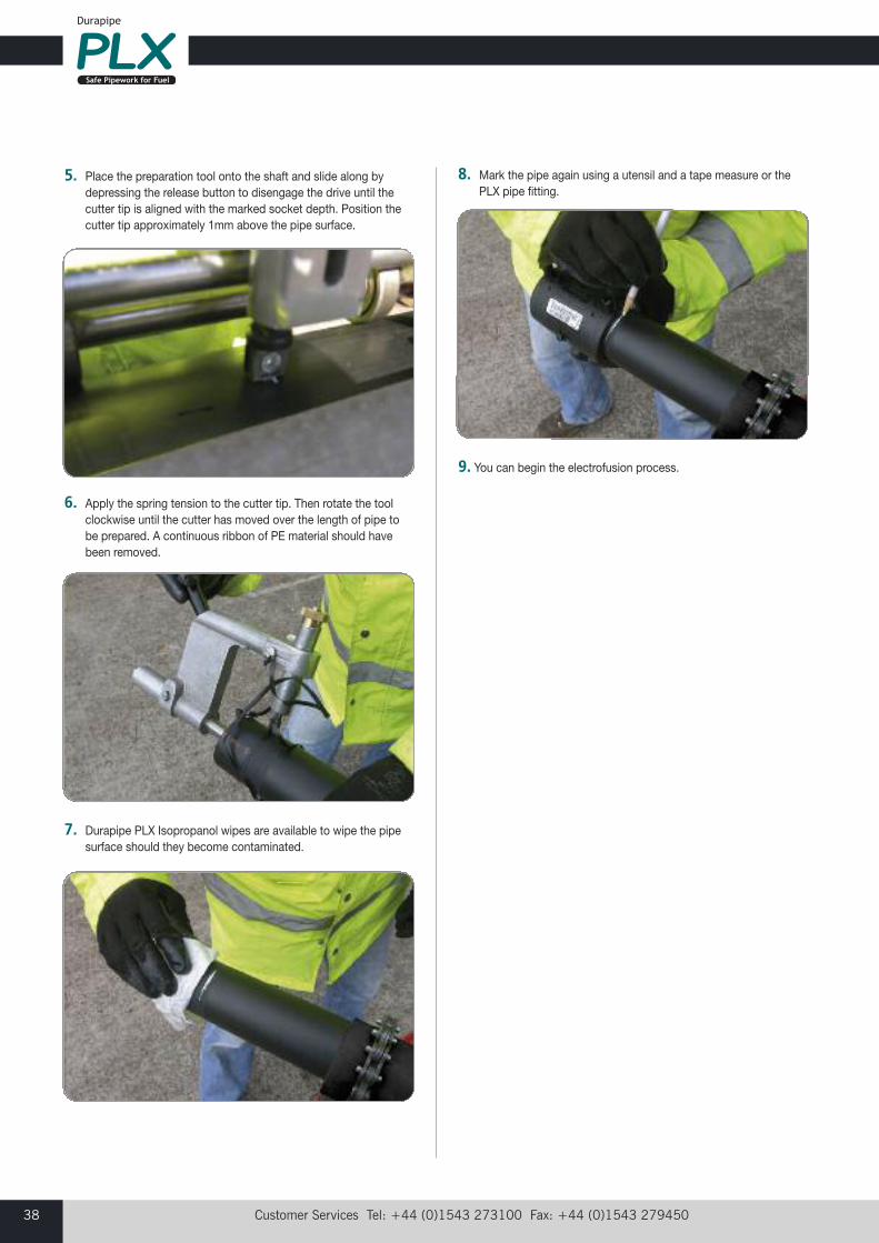
Customer Services Tel: +44 (0)1543 273100 Fax: +44 (0)1543 27945038
5. Place the preparation tool onto the shaft and slide along bydepressing the release button to disengage the drive until thecutter tip is aligned with the marked socket depth. Position thecutter tip approximately 1mm above the pipe surface.
6. Apply the spring tension to the cutter tip. Then rotate the toolclockwise until the cutter has moved over the length of pipe tobe prepared. A continuous ribbon of PE material should havebeen removed.
7. Durapipe PLX Isopropanol wipes are available to wipe the pipesurface should they become contaminated.
8. Mark the pipe again using a utensil and a tape measure or the PLX pipe fitting.
9. You can begin the electrofusion process.
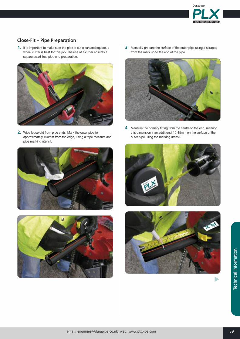
email: [email protected] web: www.plxpipe.com 39
Tech
nica
l Inf
orm
atio
n
1. It is important to make sure the pipe is cut clean and square, awheel cutter is best for this job. The use of a cutter ensures asquare swarf-free pipe end preparation.
2. Wipe loose dirt from pipe ends. Mark the outer pipe toapproximately 150mm from the edge, using a tape measure andpipe marking utensil.
3. Manually prepare the surface of the outer pipe using a scraper,from the mark up to the end of the pipe.
4. Measure the primary fitting from the centre to the end, markingthis dimension + an additional 10-15mm on the surface of theouter pipe using the marking utensil.
Close-Fit – Pipe Preparation
�
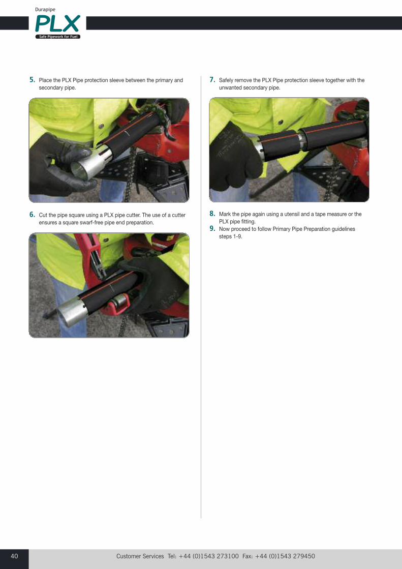
Customer Services Tel: +44 (0)1543 273100 Fax: +44 (0)1543 27945040
5. Place the PLX Pipe protection sleeve between the primary andsecondary pipe.
6. Cut the pipe square using a PLX pipe cutter. The use of a cutterensures a square swarf-free pipe end preparation.
7. Safely remove the PLX Pipe protection sleeve together with theunwanted secondary pipe.
8. Mark the pipe again using a utensil and a tape measure or thePLX pipe fitting.
9. Now proceed to follow Primary Pipe Preparation guidelines steps 1-9.
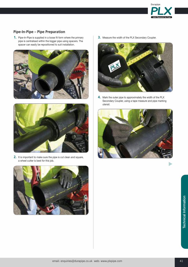
email: [email protected] web: www.plxpipe.com 41
Tech
nica
l Inf
orm
atio
n
1. Pipe-In-Pipe is supplied in a loose fit form where the primarypipe is centralised within the bigger pipe using spacers. Thespacer can easily be repositioned to suit installation.
2. It is important to make sure the pipe is cut clean and square, a wheel cutter is best for this job.
3. Measure the width of the PLX Secondary Coupler.
4. Mark the outer pipe to approximately the width of the PLXSecondary Coupler, using a tape measure and pipe markingutensil.
Pipe-In-Pipe – Pipe Preparation
�
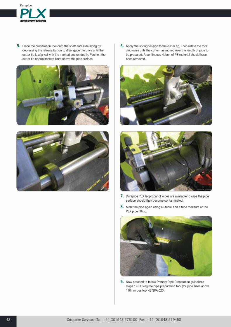
Customer Services Tel: +44 (0)1543 273100 Fax: +44 (0)1543 27945042
5. Place the preparation tool onto the shaft and slide along bydepressing the release button to disengage the drive until thecutter tip is aligned with the marked socket depth. Position thecutter tip approximately 1mm above the pipe surface.
6. Apply the spring tension to the cutter tip. Then rotate the toolclockwise until the cutter has moved over the length of pipe tobe prepared. A continuous ribbon of PE material should havebeen removed.
7. Durapipe PLX Isopropanol wipes are available to wipe the pipesurface should they become contaminated.
8. Mark the pipe again using a utensil and a tape measure or thePLX pipe fitting.
9. Now proceed to follow Primary Pipe Preparation guidelinessteps 1-9. Using the pipe preparation tool (for pipe sizes above110mm use tool 43 SPA 020).
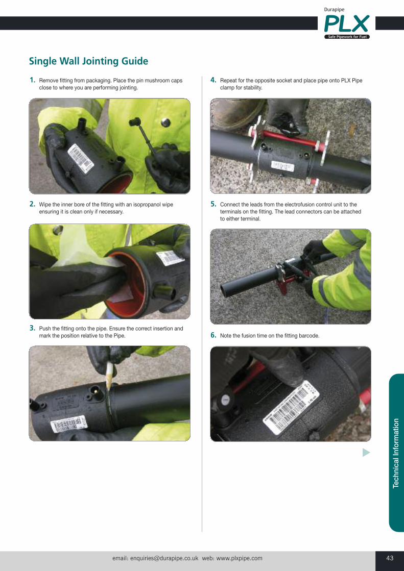
email: [email protected] web: www.plxpipe.com 43
Tech
nica
l Inf
orm
atio
n
1. Remove fitting from packaging. Place the pin mushroom capsclose to where you are performing jointing.
2. Wipe the inner bore of the fitting with an isopropanol wipeensuring it is clean only if necessary.
3. Push the fitting onto the pipe. Ensure the correct insertion andmark the position relative to the Pipe.
4. Repeat for the opposite socket and place pipe onto PLX Pipeclamp for stability.
5. Connect the leads from the electrofusion control unit to theterminals on the fitting. The lead connectors can be attachedto either terminal.
6. Note the fusion time on the fitting barcode.
Single Wall Jointing Guide
�
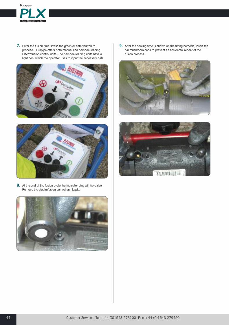
Customer Services Tel: +44 (0)1543 273100 Fax: +44 (0)1543 27945044
7. Enter the fusion time. Press the green or enter button toproceed. Durapipe offers both manual and barcode readingElectrofusion control units. The barcode reading units have alight pen, which the operator uses to input the necessary data.
8. At the end of the fusion cycle the indicator pins will have risen.Remove the electrofusion control unit leads.
9. After the cooling time is shown on the fitting barcode, insert thepin mushroom caps to prevent an accidental repeat of thefusion process.
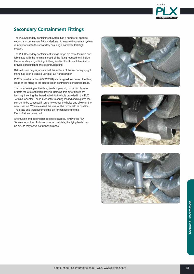
email: [email protected] web: www.plxpipe.com 45
Tech
nica
l Inf
orm
atio
n
The PLX Secondary containment system has a number of specificsecondary containment fittings designed to ensure the primary systemis independent to the secondary ensuring a complete leak tightsystem.
The PLX Secondary containment fittings range are manufactured andfabricated with the terminal shroud of the fitting reduced to fit insidethe secondary spigot fitting. A flying lead is fitted to each terminal toprovide connection to the electrofusion unit.
Before fusion begins, ensure that the surface of the secondary spigotfitting has been prepared using a PLX Hand scraper.
PLX Terminal Adaptors (43EW0004) are designed to connect the flyingleads of the fitting to the electrofusion control unit connection leads.
The outer sleeving of the flying leads is pre-cut, but left in place toprotect the wire ends from fraying. Remove this outer sleeve bytwisting, inserting the ‘bared’ wire into the hole provided in the PLXTerminal Adaptor. The PLX Adaptor is spring loaded and requires theplunger to be squeezed in order to expose the holes and allow for thewire insertion. When released the wire will be firmly held in position.The brass end then becomes the pin for connecting to theElectrofusion control unit.
After fusion and cooling periods have elapsed, remove the PLXTerminal Adaptors. As fusion is now complete, the flying leads may be cut, as they serve no further purpose.
Secondary Containment Fittings
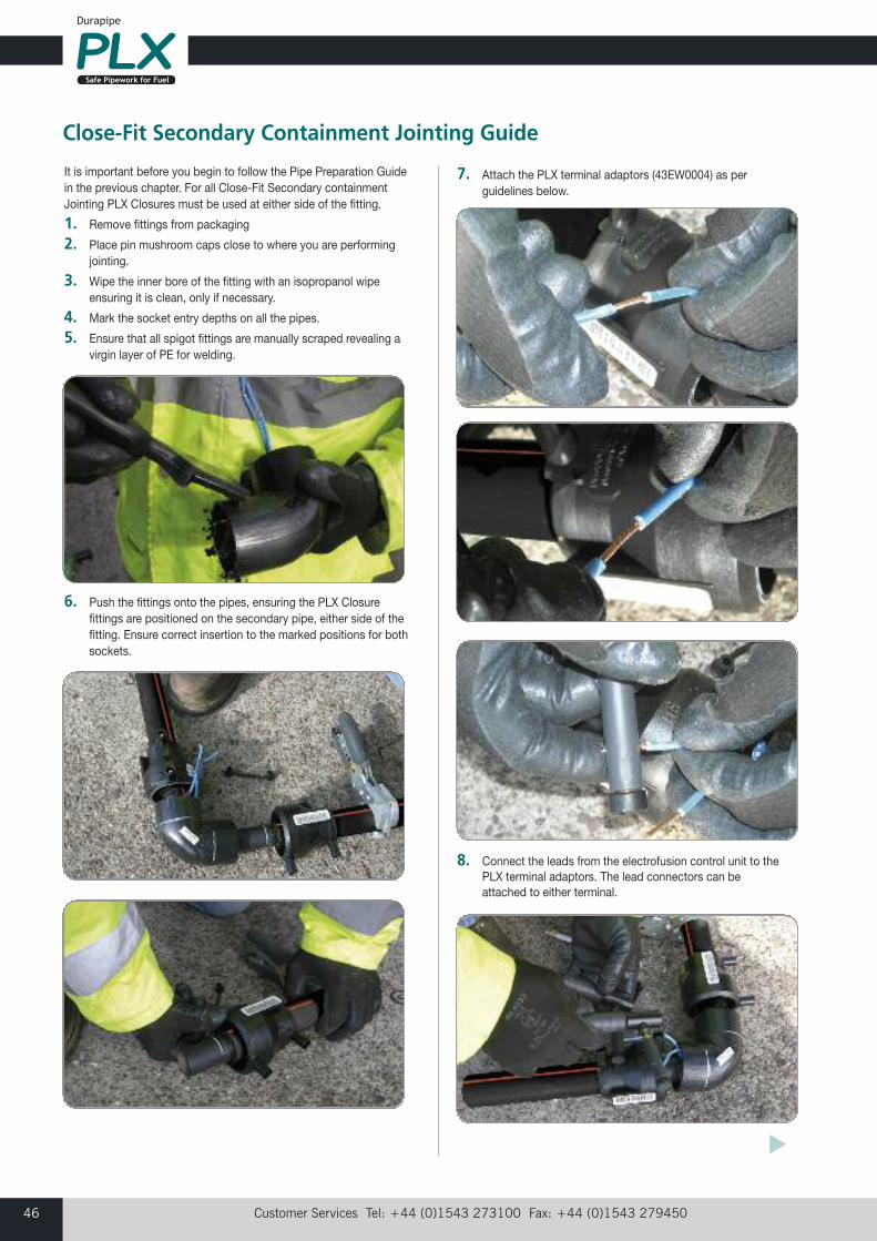
Customer Services Tel: +44 (0)1543 273100 Fax: +44 (0)1543 27945046
It is important before you begin to follow the Pipe Preparation Guidein the previous chapter. For all Close-Fit Secondary containmentJointing PLX Closures must be used at either side of the fitting.
1. Remove fittings from packaging
2. Place pin mushroom caps close to where you are performingjointing.
3. Wipe the inner bore of the fitting with an isopropanol wipeensuring it is clean, only if necessary.
4. Mark the socket entry depths on all the pipes.
5. Ensure that all spigot fittings are manually scraped revealing avirgin layer of PE for welding.
6. Push the fittings onto the pipes, ensuring the PLX Closurefittings are positioned on the secondary pipe, either side of thefitting. Ensure correct insertion to the marked positions for bothsockets.
7. Attach the PLX terminal adaptors (43EW0004) as perguidelines below.
8. Connect the leads from the electrofusion control unit to the PLX terminal adaptors. The lead connectors can beattached to either terminal.
Close-Fit Secondary Containment Jointing Guide
�
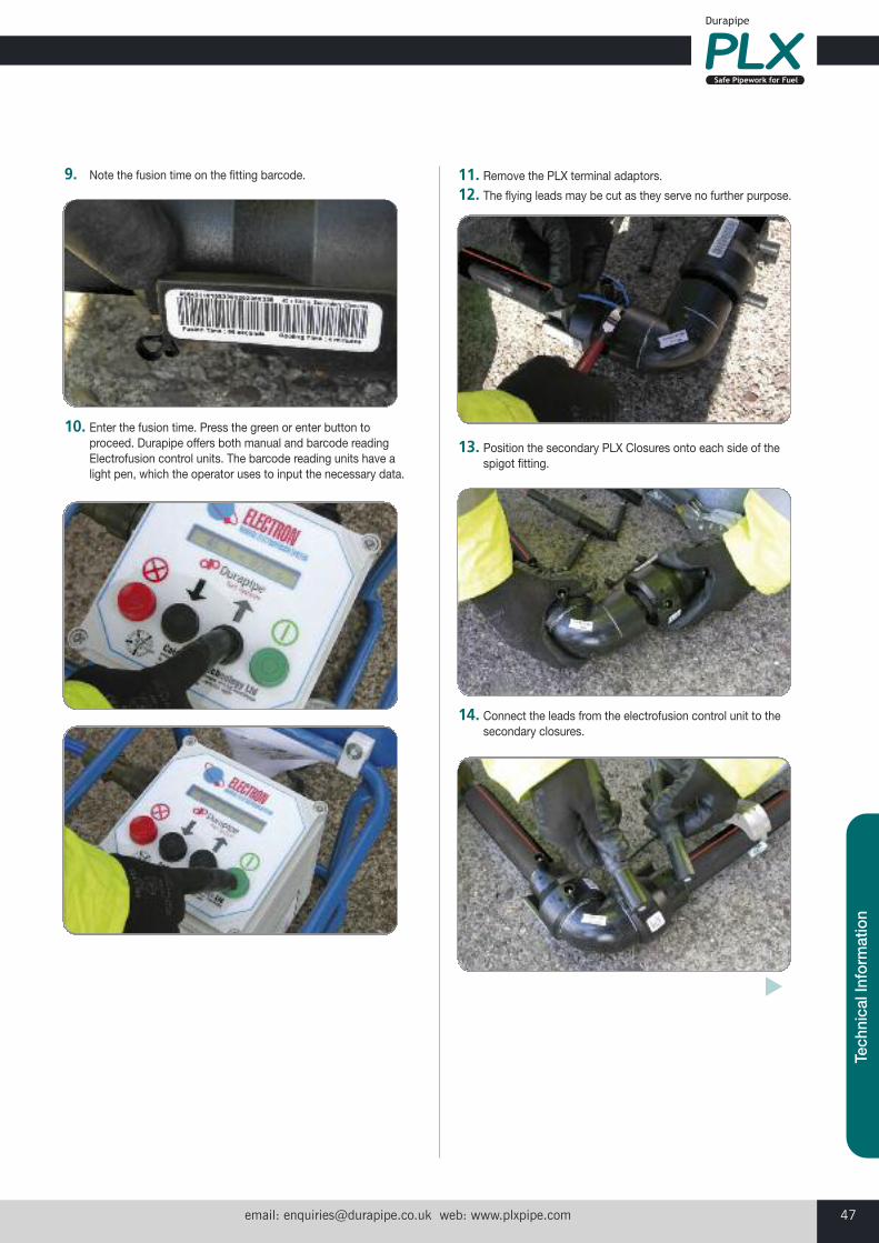
email: [email protected] web: www.plxpipe.com 47
Tech
nica
l Inf
orm
atio
n
9. Note the fusion time on the fitting barcode.
10. Enter the fusion time. Press the green or enter button toproceed. Durapipe offers both manual and barcode readingElectrofusion control units. The barcode reading units have alight pen, which the operator uses to input the necessary data.
11. Remove the PLX terminal adaptors.12. The flying leads may be cut as they serve no further purpose.
13. Position the secondary PLX Closures onto each side of thespigot fitting.
14. Connect the leads from the electrofusion control unit to thesecondary closures.
�
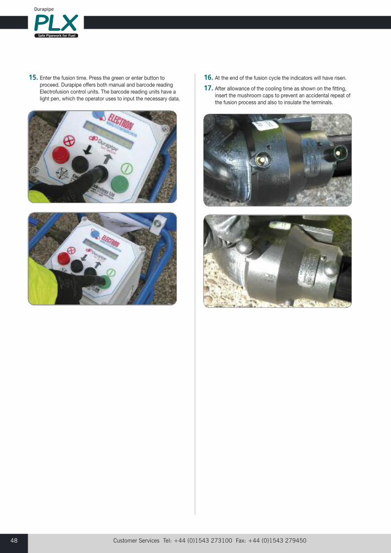
Customer Services Tel: +44 (0)1543 273100 Fax: +44 (0)1543 27945048
15. Enter the fusion time. Press the green or enter button toproceed. Durapipe offers both manual and barcode readingElectrofusion control units. The barcode reading units have alight pen, which the operator uses to input the necessary data.
16. At the end of the fusion cycle the indicators will have risen.
17. After allowance of the cooling time as shown on the fitting,insert the mushroom caps to prevent an accidental repeat ofthe fusion process and also to insulate the terminals.
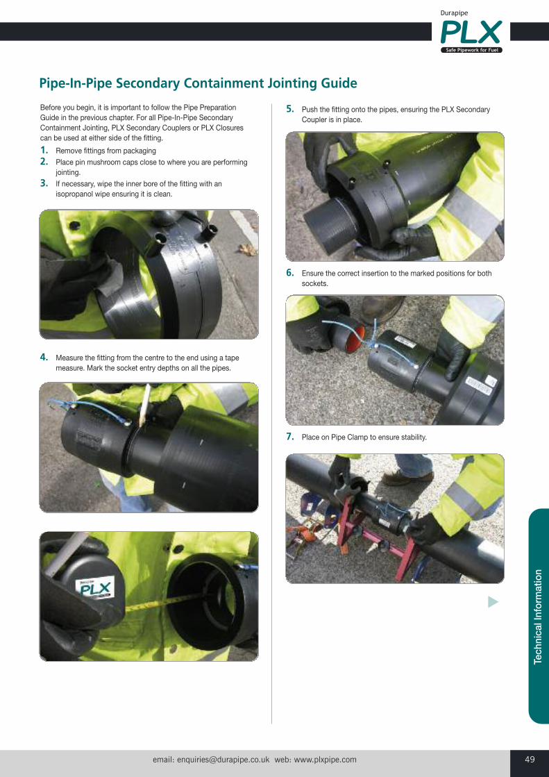
email: [email protected] web: www.plxpipe.com 49
Tech
nica
l Inf
orm
atio
n
Before you begin, it is important to follow the Pipe PreparationGuide in the previous chapter. For all Pipe-In-Pipe SecondaryContainment Jointing, PLX Secondary Couplers or PLX Closurescan be used at either side of the fitting.
1. Remove fittings from packaging
2. Place pin mushroom caps close to where you are performingjointing.
3. If necessary, wipe the inner bore of the fitting with anisopropanol wipe ensuring it is clean.
4. Measure the fitting from the centre to the end using a tapemeasure. Mark the socket entry depths on all the pipes.
5. Push the fitting onto the pipes, ensuring the PLX Secondary Coupler is in place.
6. Ensure the correct insertion to the marked positions for bothsockets.
7. Place on Pipe Clamp to ensure stability.
Pipe-In-Pipe Secondary Containment Jointing Guide
�

Customer Services Tel: +44 (0)1543 273100 Fax: +44 (0)1543 27945050
8. Attach the PLX terminal adaptors (43EW0004) as perguidelines below.
9. Connect the leads from the electrofusion control unit to thePLX terminal adaptors. The lead connectors can be attachedto either terminal.
10. Note the fusion time on the fitting barcode.11. Enter the fusion time. Press the green or enter button to
proceed. Durapipe offers both manual and barcode readingElectrofusion control units. The barcode reading units have alight pen, which the operator uses to input the necessarydata.
12. Remove the PLX terminal adaptors.13. The flying leads may be tucked into the space between the
primary and secondary pipes, or they can be cut as theyserve no further purpose.
�
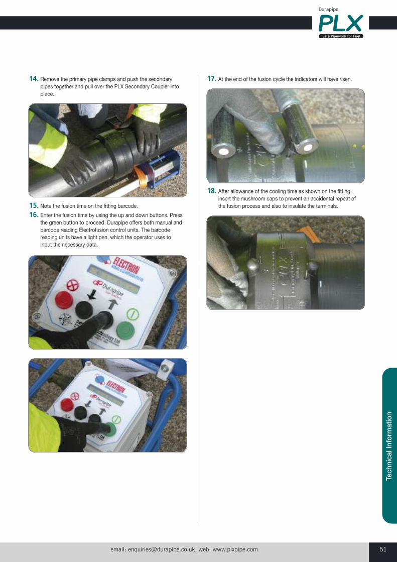
email: [email protected] web: www.plxpipe.com 51
Tech
nica
l Inf
orm
atio
n
14. Remove the primary pipe clamps and push the secondarypipes together and pull over the PLX Secondary Coupler intoplace.
15. Note the fusion time on the fitting barcode.16. Enter the fusion time by using the up and down buttons. Press
the green button to proceed. Durapipe offers both manual andbarcode reading Electrofusion control units. The barcodereading units have a light pen, which the operator uses toinput the necessary data.
17. At the end of the fusion cycle the indicators will have risen.
18. After allowance of the cooling time as shown on the fitting,insert the mushroom caps to prevent an accidental repeat ofthe fusion process and also to insulate the terminals.
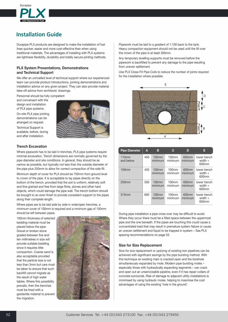
Customer Services Tel: +44 (0)1543 273100 Fax: +44 (0)1543 27945052
Durapipe PLX products are designed to make the installation of fuellines quicker, easier and more cost-effective than when usingtraditional materials. The advantages of installing with PLX systemsare lightness flexibility, durability and totally secure jointing methods.
PLX System Presentations, Demonstrations and Technical SupportWe offer an unrivalled level of technical support where our experiencedteam can provide product introductions, jointing demonstrations andinstallation advice on any given project. They can also provide materialtake-off advice from architects’ drawings.
Personnel should be fully competent and conversant with thedesign and installation of PLX pipe systems.
On-site PLX pipe jointingdemonstrations can bearranged on request.
Technical Support is available, before, during and after installation.
Trench ExcavationWhere pipework has to be laid in trenches, PLX pipe systems requireminimal excavation. Trench dimensions are normally governed by thepipe diameter and site conditions. In general, they should be asnarrow as possible, but typically not less than the outside diameter ofthe pipe plus 250mm to allow for correct compaction of the side fill.
Minimum depth of cover for PLX should be 750mm from ground levelto crown of the pipe. It is acceptable to lay pipes directly on thebottom of the trench, provided that the soil is uniform, relatively softand fine grained and free from large flints, stones and other hardobjects, which could damage the pipe wall. The trench bottom shouldbe brought to an even finish to provide consistent support to the pipesalong their complete length.
Where pipes are to be laid side by side in wide/open trenches, aminimum cover of 100mm is required and a minimum gap of 100mmshould be left between pipes.
100mm thickness of selectedbedding material must beplaced below the pipe.Gravel or broken stonegraded between five and ten millimetres in size willprovide suitable beddingsince it requires littlecompaction. Coarse sand isalso acceptable providedthat the particle size is notless than 3mm but care mustbe taken to ensure that suchbackfill cannot migrate asthe result of high watertables. Where this possibilityprevails, then the trenchesmust be lined with ageotextile material to preventthe migration.
Pipework must be laid to a gradient of 1:100 back to the tank. Heavy compaction equipment should not be used until the fill over the crown of the pipe is at least 300mm.
Any temporary levelling supports must be removed before thepipework is backfilled to prevent any damage to the pipe resultingfrom uneven settlement.
Use PLX Close-Fit Pipe Coils to reduce the number of joints requiredfor the installation where possible.
During pipe installation a pipe cross over may be difficult to avoid.Where they occur there must be a filled space between the uppermostpipe and the one beneath. If the pipes are touching this could cause aconcentrated load that may result in premature system failure or causean uneven settlement and liquid to be trapped in system – See PLXspacing recommendations on page 53.
Size for Size ReplacementSize-for size replacement or upsizing of existing iron pipelines can beachieved with significant savings by the pipe bursting method. Withthis technique an existing main is cracked open and the boreholesimultaneously expanded by mole. Modern pipe bursting moles –especially those with hydraulically expanding segments – can crackand open out an unserviceable pipeline, even if it has repair collars ofconcrete surrounds. Risk of damage to adjacent utility installations isminimised by using hydraulic moles, helping to maximise the costadvantages of using the existing ‘hole in the ground’.
Installation Guide
Pipe Diameter A B C D E
110mm 450 100mm 100mm 400mm lower trench and below minimum minimum minimum width +
600mm
150mm 450 100mm 100mm 400mm lower trenchminimum minimum minimum width +
600mm
250mm 500 100mm 100mm 400mm lower trenchminimum minimum minimum width +
600mm
315mm 600 100mm 100mm 400mm lower trenchminimum minimum minimum width +
600mm
E
A
D
C
B
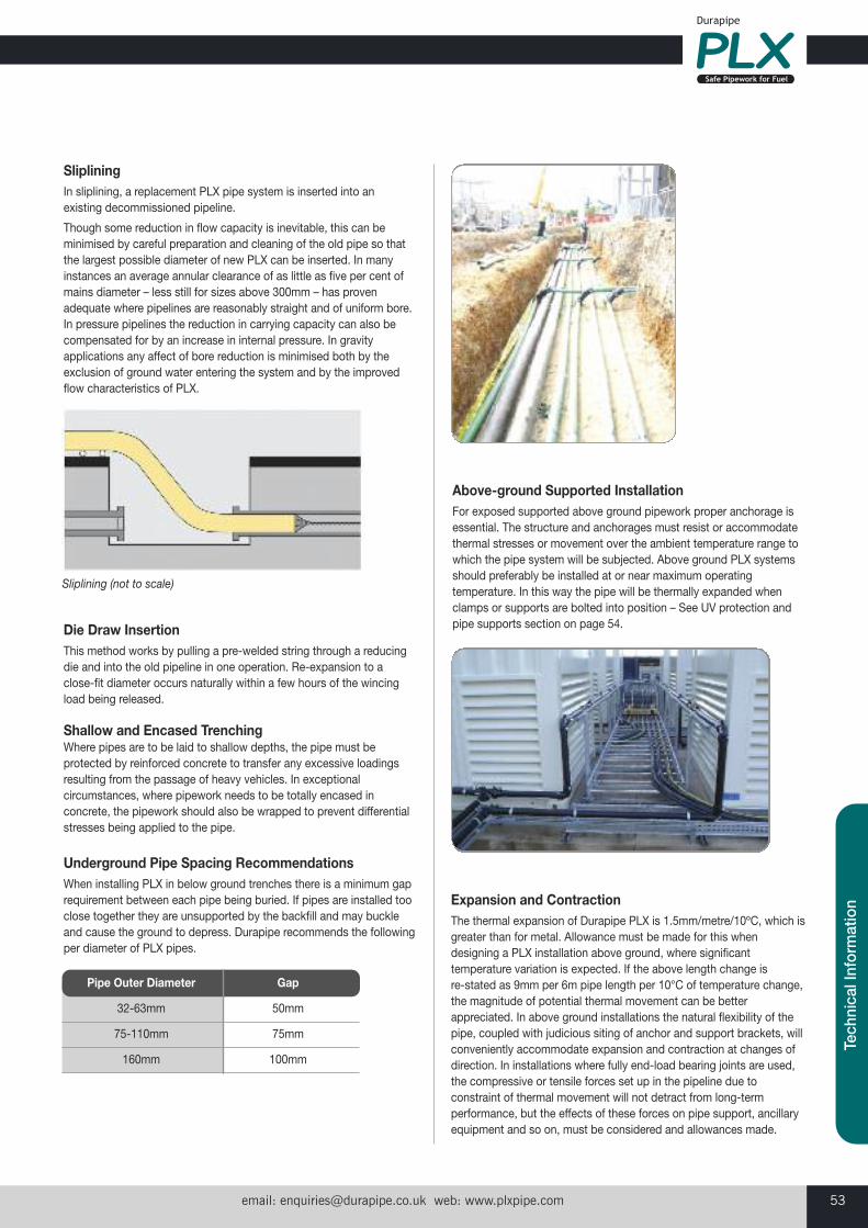
email: [email protected] web: www.plxpipe.com 53
Tech
nica
l Inf
orm
atio
n
SlipliningIn sliplining, a replacement PLX pipe system is inserted into an existing decommissioned pipeline.
Though some reduction in flow capacity is inevitable, this can beminimised by careful preparation and cleaning of the old pipe so thatthe largest possible diameter of new PLX can be inserted. In manyinstances an average annular clearance of as little as five per cent ofmains diameter – less still for sizes above 300mm – has provenadequate where pipelines are reasonably straight and of uniform bore.In pressure pipelines the reduction in carrying capacity can also becompensated for by an increase in internal pressure. In gravityapplications any affect of bore reduction is minimised both by theexclusion of ground water entering the system and by the improvedflow characteristics of PLX.
Die Draw InsertionThis method works by pulling a pre-welded string through a reducingdie and into the old pipeline in one operation. Re-expansion to aclose-fit diameter occurs naturally within a few hours of the wincingload being released.
Shallow and Encased TrenchingWhere pipes are to be laid to shallow depths, the pipe must beprotected by reinforced concrete to transfer any excessive loadingsresulting from the passage of heavy vehicles. In exceptionalcircumstances, where pipework needs to be totally encased inconcrete, the pipework should also be wrapped to prevent differentialstresses being applied to the pipe.
Underground Pipe Spacing RecommendationsWhen installing PLX in below ground trenches there is a minimum gaprequirement between each pipe being buried. If pipes are installed tooclose together they are unsupported by the backfill and may buckleand cause the ground to depress. Durapipe recommends the followingper diameter of PLX pipes.
Above-ground Supported InstallationFor exposed supported above ground pipework proper anchorage isessential. The structure and anchorages must resist or accommodatethermal stresses or movement over the ambient temperature range towhich the pipe system will be subjected. Above ground PLX systemsshould preferably be installed at or near maximum operatingtemperature. In this way the pipe will be thermally expanded whenclamps or supports are bolted into position – See UV protection andpipe supports section on page 54.
Pipe Outer Diameter Gap
32-63mm 50mm
75-110mm 75mm
160mm 100mm
Sliplining (not to scale)
Expansion and ContractionThe thermal expansion of Durapipe PLX is 1.5mm/metre/10ºC, which isgreater than for metal. Allowance must be made for this whendesigning a PLX installation above ground, where significanttemperature variation is expected. If the above length change is re-stated as 9mm per 6m pipe length per 10°C of temperature change,the magnitude of potential thermal movement can be betterappreciated. In above ground installations the natural flexibility of thepipe, coupled with judicious siting of anchor and support brackets, willconveniently accommodate expansion and contraction at changes ofdirection. In installations where fully end-load bearing joints are used,the compressive or tensile forces set up in the pipeline due toconstraint of thermal movement will not detract from long-termperformance, but the effects of these forces on pipe support, ancillaryequipment and so on, must be considered and allowances made.
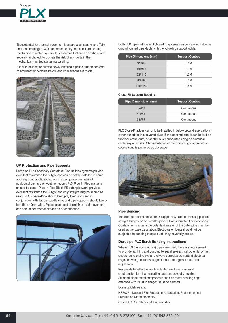
Customer Services Tel: +44 (0)1543 273100 Fax: +44 (0)1543 27945054
The potential for thermal movement is a particular issue where (fullyend-load bearing) PLX is connected to any non end-load bearingmechanically jointed system. It is essential that such transitions aresecurely anchored, to obviate the risk of any joints in themechanically jointed system separating.
It is also prudent to allow a newly installed pipeline time to conformto ambient temperature before end connections are made.
Pipe Dimensions (mm) Support Centres
32#63 1.0M
50#90 1.1M
63#110 1.2M
90#160 1.5M
110#160 1.5M
Close-Fit Support Spacing
Pipe Dimensions (mm) Support Centres
32#40 Continuous
50#63 Continuous
63#75 Continuous
UV Protection and Pipe SupportsDurapipe PLX Secondary Contained Pipe-In-Pipe systems provideexcellent resistance to UV light and can be safely installed in someabove ground applications. For greatest protection againstaccidental damage or weathering, only PLX Pipe-In-Pipe systemsshould be used. Pipe-In-Pipe Black PE outer pipework providesexcellent resistance to UV light and only straight lengths should beused. PLX Pipe-In-Pipe should be rigidly fixed and used inconjunction with flat bar saddle clips and pipe supports should be noless than 40mm wide. Pipe clips should permit free axial movementand should not restrict expansion or contraction.
Both PLX Pipe-In-Pipe and Close-Fit systems can be installed in belowground formed pipe ducts with the following support guide:
PLX Close-Fit pipes can only be installed in below ground applications,either buried, or in a covered duct. If in a covered duct it can be laid onthe floor of the duct, or continuously supported using an electricalcable tray or similar. After installation of the pipes a light aggregate orcoarse sand is preferred as coverage.
Pipe BendingThe minimum bend radius for Durapipe PLX product lines supplied instraight lengths is 25 times the pipe outside diameter. For SecondaryContainment systems the outside diameter of the outer pipe must beused as the base calculation. Electrofusion joints should not besubjected to bending stresses until they have fully cooled.
Durapipe PLX Earth Bonding InstructionsWhere PLX (non-conductive) pipes are used, there is a requirementto provide earthing and bonding to equalise electrical potential of theunderground piping system. Always consult a competent electricalengineer with good knowledge of local and regional rules andregulations.
Key points for effective earth establishment are: Ensure allelectrofusion terminal insulating caps are correctly inserted. All stand alone metal components such as metal backing ringsattached with PE stub flanges must be earthed.
Some guidelines are:
NFPA77 – National Fire Protection Association, RecommendedPractice on Static Electricity
CENELEC CLC/TR 50404 Electrostatics
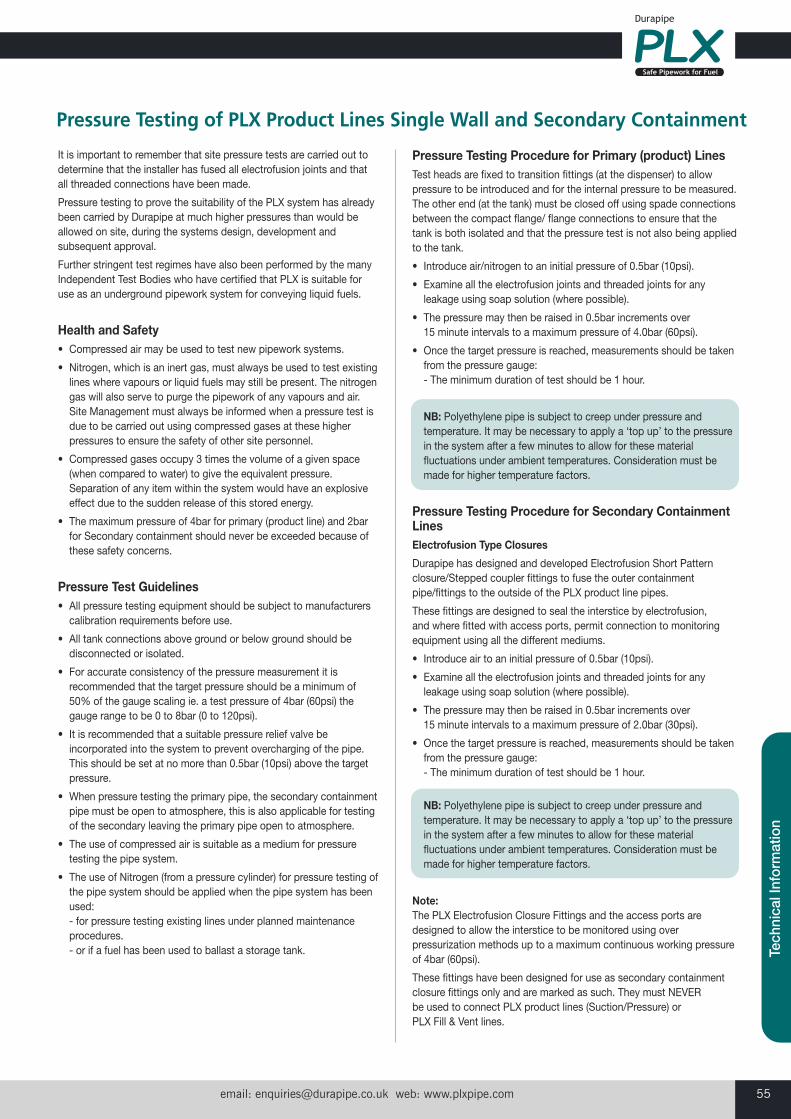
email: [email protected] web: www.plxpipe.com 55
Tech
nica
l Inf
orm
atio
n
It is important to remember that site pressure tests are carried out todetermine that the installer has fused all electrofusion joints and thatall threaded connections have been made.
Pressure testing to prove the suitability of the PLX system has alreadybeen carried by Durapipe at much higher pressures than would beallowed on site, during the systems design, development andsubsequent approval.
Further stringent test regimes have also been performed by the manyIndependent Test Bodies who have certified that PLX is suitable foruse as an underground pipework system for conveying liquid fuels.
Health and Safety• Compressed air may be used to test new pipework systems.
• Nitrogen, which is an inert gas, must always be used to test existinglines where vapours or liquid fuels may still be present. The nitrogengas will also serve to purge the pipework of any vapours and air. Site Management must always be informed when a pressure test isdue to be carried out using compressed gases at these higherpressures to ensure the safety of other site personnel.
• Compressed gases occupy 3 times the volume of a given space(when compared to water) to give the equivalent pressure.Separation of any item within the system would have an explosiveeffect due to the sudden release of this stored energy.
• The maximum pressure of 4bar for primary (product line) and 2barfor Secondary containment should never be exceeded because ofthese safety concerns.
Pressure Test Guidelines• All pressure testing equipment should be subject to manufacturerscalibration requirements before use.
• All tank connections above ground or below ground should bedisconnected or isolated.
• For accurate consistency of the pressure measurement it isrecommended that the target pressure should be a minimum of50% of the gauge scaling ie. a test pressure of 4bar (60psi) thegauge range to be 0 to 8bar (0 to 120psi).
• It is recommended that a suitable pressure relief valve beincorporated into the system to prevent overcharging of the pipe.This should be set at no more than 0.5bar (10psi) above the targetpressure.
• When pressure testing the primary pipe, the secondary containmentpipe must be open to atmosphere, this is also applicable for testingof the secondary leaving the primary pipe open to atmosphere.
• The use of compressed air is suitable as a medium for pressuretesting the pipe system.
• The use of Nitrogen (from a pressure cylinder) for pressure testing ofthe pipe system should be applied when the pipe system has beenused:- for pressure testing existing lines under planned maintenanceprocedures.- or if a fuel has been used to ballast a storage tank.
Pressure Testing Procedure for Primary (product) LinesTest heads are fixed to transition fittings (at the dispenser) to allowpressure to be introduced and for the internal pressure to be measured.The other end (at the tank) must be closed off using spade connectionsbetween the compact flange/ flange connections to ensure that thetank is both isolated and that the pressure test is not also being appliedto the tank.
• Introduce air/nitrogen to an initial pressure of 0.5bar (10psi).
• Examine all the electrofusion joints and threaded joints for anyleakage using soap solution (where possible).
• The pressure may then be raised in 0.5bar increments over 15 minute intervals to a maximum pressure of 4.0bar (60psi).
• Once the target pressure is reached, measurements should be takenfrom the pressure gauge:- The minimum duration of test should be 1 hour.
NB: Polyethylene pipe is subject to creep under pressure andtemperature. It may be necessary to apply a ‘top up’ to the pressurein the system after a few minutes to allow for these materialfluctuations under ambient temperatures. Consideration must bemade for higher temperature factors.
Pressure Testing Procedure for Secondary ContainmentLinesElectrofusion Type Closures
Durapipe has designed and developed Electrofusion Short Patternclosure/Stepped coupler fittings to fuse the outer containmentpipe/fittings to the outside of the PLX product line pipes.
These fittings are designed to seal the interstice by electrofusion, and where fitted with access ports, permit connection to monitoringequipment using all the different mediums.
• Introduce air to an initial pressure of 0.5bar (10psi).
• Examine all the electrofusion joints and threaded joints for anyleakage using soap solution (where possible).
• The pressure may then be raised in 0.5bar increments over 15 minute intervals to a maximum pressure of 2.0bar (30psi).
• Once the target pressure is reached, measurements should be takenfrom the pressure gauge: - The minimum duration of test should be 1 hour.
NB: Polyethylene pipe is subject to creep under pressure andtemperature. It may be necessary to apply a ‘top up’ to the pressurein the system after a few minutes to allow for these materialfluctuations under ambient temperatures. Consideration must bemade for higher temperature factors.
Note:The PLX Electrofusion Closure Fittings and the access ports aredesigned to allow the interstice to be monitored using overpressurization methods up to a maximum continuous working pressureof 4bar (60psi).
These fittings have been designed for use as secondary containmentclosure fittings only and are marked as such. They must NEVER be used to connect PLX product lines (Suction/Pressure) or PLX Fill & Vent lines.
Pressure Testing of PLX Product Lines Single Wall and Secondary Containment

Customer Services Tel: +44 (0)1543 273100 Fax: +44 (0)1543 27945056
Before Durapipe PLX pipe can be installed, ensure that the site is prepared. With all PLX installations there will be requirements for connectionto either above or below ground fuel storage tanks, or other form of system apparatus. Installations with underground storage tanks will alsohave Fill & Vent lines to maintain constant pressure in the tank.
Application Specific Installation Overview
Forecourt Applications
PLX is installed for the key applicationswithin a forecourt:• Offset Fill • Vents• Vapour Recovery• Pump, Dispenser and Tank Connections• Tank Chamber Connections
VentsVents are provided in order to allow air to be drawn into thetanks as liquid is dispensed and to act as an emergencypressure release for the tank vapour collection system. Thesmooth bore of PLX Fill & Vent pipe will assist air/vapour flowand the condensed vapour return to its UST.
Typical sizes used for this application are 63mm and 90mm.Available products are PLX Fill & Vent pipe (SDR17),electrofusion elbows, couplers, tees and PLX transitionfittings for safe connection to the vent and storage tank.
Two methods are used to move the fuel from the tank to the dispensers:
Suction: this is when the dispensing pumps create a vacuum which draws the fuel fromthe tank to the dispenser.
Pressure: this is when submersible pumps in the storage tanks create a positivepressure which pushes the fuel to the dispensers.
Products for these systems:
Suction uses predominantly single wall product. This is because if there was a leak thevacuum prevents the fuel escaping.
Pressure uses secondary containment product. If there is a leak the fuel will becontained in the secondary pipe until the fault is detected and repaired.
Offset Fill An offset fill pipe is used for filling each of the undergroundtanks from a remote point, usually at the perimeter of theforecourt. The smooth bore of the lined PLX Fill & Vent pipeimproves flow and reduces the fill time of the UndergroundStorage Tanks (USTs). With minimal available gravity head,frictional losses must be considered operating under gravityhead, the fill pipe should be considered as a pressure systemand can be installed using PLX Secondary Contained systems.
Typical sizes used for this application are 90mm/110mm.
Available products are PLX Fill & Vent pipe (SDR17),electrofusion elbows, couplers, tees and transition fittings.
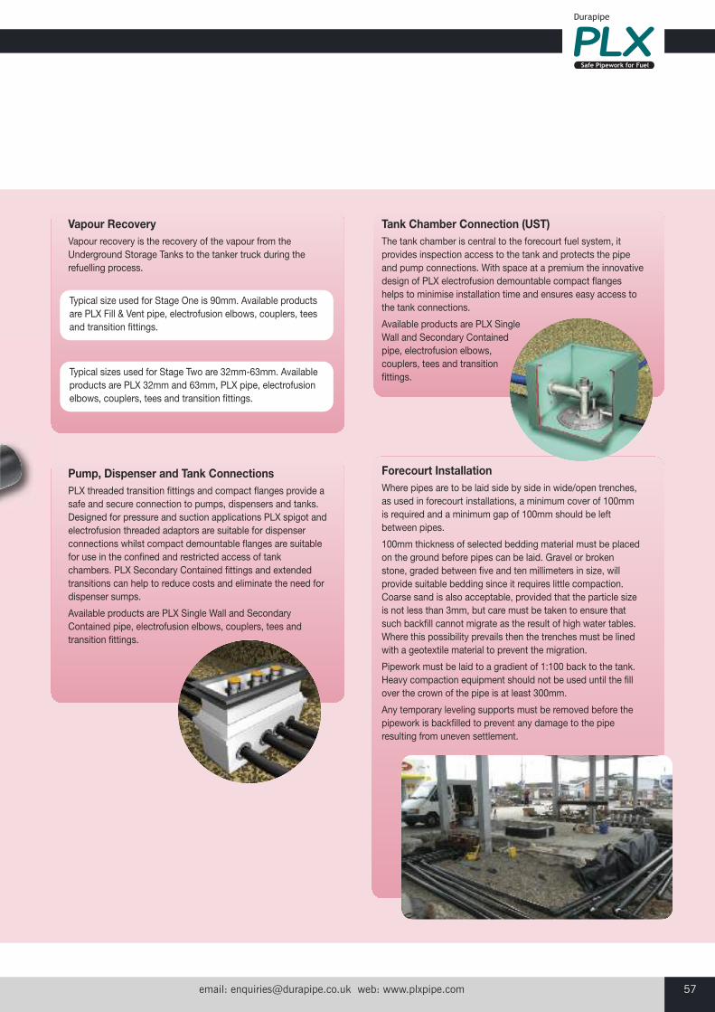
email: [email protected] web: www.plxpipe.com 57
Tank Chamber Connection (UST)The tank chamber is central to the forecourt fuel system, itprovides inspection access to the tank and protects the pipeand pump connections. With space at a premium the innovativedesign of PLX electrofusion demountable compact flangeshelps to minimise installation time and ensures easy access tothe tank connections.
Available products are PLX SingleWall and Secondary Containedpipe, electrofusion elbows,couplers, tees and transitionfittings.
Vapour RecoveryVapour recovery is the recovery of the vapour from theUnderground Storage Tanks to the tanker truck during therefuelling process.
Forecourt InstallationWhere pipes are to be laid side by side in wide/open trenches,as used in forecourt installations, a minimum cover of 100mmis required and a minimum gap of 100mm should be leftbetween pipes.
100mm thickness of selected bedding material must be placedon the ground before pipes can be laid. Gravel or brokenstone, graded between five and ten millimeters in size, willprovide suitable bedding since it requires little compaction.Coarse sand is also acceptable, provided that the particle sizeis not less than 3mm, but care must be taken to ensure thatsuch backfill cannot migrate as the result of high water tables.Where this possibility prevails then the trenches must be linedwith a geotextile material to prevent the migration.
Pipework must be laid to a gradient of 1:100 back to the tank.Heavy compaction equipment should not be used until the fillover the crown of the pipe is at least 300mm.
Any temporary leveling supports must be removed before thepipework is backfilled to prevent any damage to the piperesulting from uneven settlement.
Pump, Dispenser and Tank ConnectionsPLX threaded transition fittings and compact flanges provide asafe and secure connection to pumps, dispensers and tanks.Designed for pressure and suction applications PLX spigot andelectrofusion threaded adaptors are suitable for dispenserconnections whilst compact demountable flanges are suitablefor use in the confined and restricted access of tankchambers. PLX Secondary Contained fittings and extendedtransitions can help to reduce costs and eliminate the need fordispenser sumps.
Available products are PLX Single Wall and SecondaryContained pipe, electrofusion elbows, couplers, tees andtransition fittings.
Typical size used for Stage One is 90mm. Available productsare PLX Fill & Vent pipe, electrofusion elbows, couplers, teesand transition fittings.
Typical sizes used for Stage Two are 32mm-63mm. Availableproducts are PLX 32mm and 63mm, PLX pipe, electrofusionelbows, couplers, tees and transition fittings.
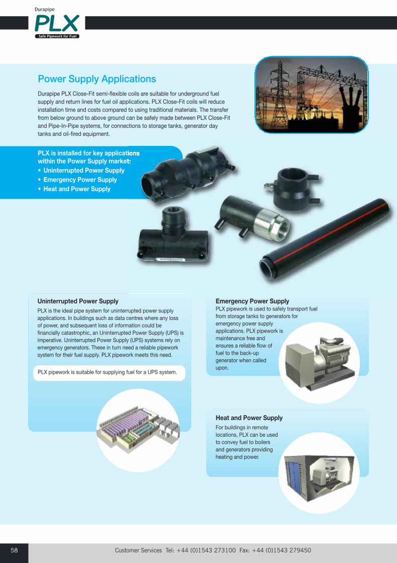
Customer Services Tel: +44 (0)1543 273100 Fax: +44 (0)1543 27945058
Power Supply ApplicationsDurapipe PLX Close-Fit semi-flexible coils are suitable for underground fuelsupply and return lines for fuel oil applications. PLX Close-Fit coils will reduceinstallation time and costs compared to using traditional materials. The transferfrom below ground to above ground can be safely made between PLX Close-Fitand Pipe-In-Pipe systems, for connections to storage tanks, generator daytanks and oil-fired equipment.
Emergency Power SupplyPLX pipework is used to safely transport fuelfrom storage tanks to generators foremergency power supplyapplications. PLX pipework ismaintenance free andensures a reliable flow offuel to the back-upgenerator when calledupon.
Uninterrupted Power SupplyPLX is the ideal pipe system for uninterrupted power supplyapplications. In buildings such as data centres where any lossof power, and subsequent loss of information could befinancially catastrophic, an Uninterrupted Power Supply (UPS) isimperative. Uninterrupted Power Supply (UPS) systems rely onemergency generators. These in turn need a reliable pipeworksystem for their fuel supply. PLX pipework meets this need.
PLX pipework is suitable for supplying fuel for a UPS system.
PLX is installed for key applicationswithin the Power Supply market:• Uninterrupted Power Supply• Emergency Power Supply• Heat and Power Supply
Heat and Power SupplyFor buildings in remotelocations, PLX can be used to convey fuel to boilersand generators providingheating and power.

email: [email protected] web: www.plxpipe.com 59
Connection to System ApparatusPLX Transition fittings ensure the safe continuous flow offuel when connecting to metal threaded system apparatus. Each transition fitting has been innovatively designed andmanufactured using the highest quality PE and a widerange of metals. With the process of installation in mind;each fitting is developed to save time and costs during theinstallation process.
Tank Chamber Connection (UST)The tank chamber is central to the forecourt fuel system, itprovides inspection access to the tank and protects the pipeand pump connections. With space at a premium theinnovative design of PLX electrofusion demountable compactflanges helps to minimise installation time and ensures easyaccess to the tank connections.
Available products are PLX Secondary Containment pipe,electrofusion elbows, couplers, tees and transition fittings.
Power Supply InstallationThese installations could be trenching or require pipework to besituated within a duct. PLX Pipe-In-Pipe systems are UVresistant and can be safely installed in some above groundapplications with the use of pipe supports. Please refer to theinstallation guidelines and contact our Technical Support Teamif you require further information.
Offset Fill & VentSpecifically designed PLX Fill & Vent pipe reduces time andcosts when filling underground fuel storage tanks. PLX Fill & Vent is also suitable for venting the system to ensurethe tank and associated pipework are pressure balanced.
An ‘offset fill’ is used for filling each of the underground tanks. With minimal available gravity head, frictional losses must beconsidered. Even though operating under gravity head, fill pipeshould be considered as a pressure system and can beinstalled using PLX secondary contained systems.
Vent equipment ensures the safe holding and balancing ofvapour control of the underground storage tanks. Vents andvapour recovery systems ensure that Underground StorageTanks (USTs) and associated pipework are pressure balancedand that air and fuel vapour are safely recovered.
Typical sizes used for this application are 63mm, 90mm and110mm. Available products are PLX and PLX Fill & Vent pipe,electrofusion elbows, couplers, tees and transition fittings forsafe connection to the offset fill and storage tank.

Customer Services Tel: +44 (0)1543 273100 Fax: +44 (0)1543 27945060
Transport RefuellingThe pipework requirements when conveying fuel for transportation vehicles viamass distribution can be complex and diverse, Reliability of the pipe system is ofparamount importance.
Naturally, all modes of transport require fuel to enable them to function asrequired, for example marinas, airports, railway stations and haulage distributiondepots all need fuel. Durapipe PLX large diameter specialist pipe systems arerequired to meet the needs of bulk refuelling for centralised depots that feedvarious types of transport vehicles.
PLX is installed for key applications within the Transport Refuelling market:• Aviation• Haulage or Distribution Centres• Rail• Marinas• Tunnels
RailCompact, robust and maintenance free, PLX is protectedagainst accidental damage and freezing conditions. Easilyinstalled into pre-formed shallow ducts, PLX systems aresuitable for fuel and lubrication oildispensing applications.
AviationPLX is corrosion resistant, as well as being compatible with civiland military grade aviation fuels. PLX ensures a clean supply toall aviation refuelling activities. PLX pipe systems, together withour selection of fittings to suit, aresuitable for these types ofinstallations.
MarinasPLX Secondary Contained pipework provides a secureenvironment for bulk transfer of marine fuels to storage tanks,during vessel refuelling, bunkering and bilge water pumpingoperations. PLX Pipe-In-Pipe systems are corrosion, UV andabuse resistant ensuring outdoor weathering does notpenetrate the pipework system.With a high resistance tomarine fuel oils, PLX is acost-effective solution formarine related fueltransfer.
Haulage or Distribution CentresPLX is suitable to convey a wide range of fuels including petrol,diesel, biofuels and AdBlue®. The added protection of theSecondary Containment pipework provides a leak tight systemsuitable for high-speed suction or pumped applications.
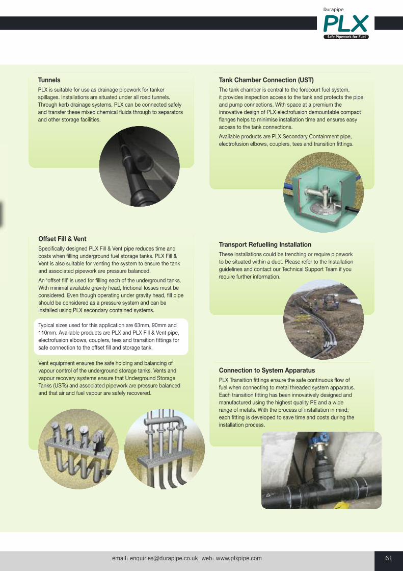
email: [email protected] web: www.plxpipe.com 61
TunnelsPLX is suitable for use as drainage pipework for tankerspillages. Installations are situated under all road tunnels.Through kerb drainage systems, PLX can be connected safelyand transfer these mixed chemical fluids through to separatorsand other storage facilities.
Offset Fill & VentSpecifically designed PLX Fill & Vent pipe reduces time andcosts when filling underground fuel storage tanks. PLX Fill &Vent is also suitable for venting the system to ensure the tankand associated pipework are pressure balanced.
An ‘offset fill’ is used for filling each of the underground tanks. With minimal available gravity head, frictional losses must beconsidered. Even though operating under gravity head, fill pipeshould be considered as a pressure system and can beinstalled using PLX secondary contained systems.
Vent equipment ensures the safe holding and balancing ofvapour control of the underground storage tanks. Vents andvapour recovery systems ensure that Underground StorageTanks (USTs) and associated pipework are pressure balancedand that air and fuel vapour are safely recovered.
Typical sizes used for this application are 63mm, 90mm and110mm. Available products are PLX and PLX Fill & Vent pipe,electrofusion elbows, couplers, tees and transition fittings forsafe connection to the offset fill and storage tank.
Connection to System ApparatusPLX Transition fittings ensure the safe continuous flow offuel when connecting to metal threaded system apparatus. Each transition fitting has been innovatively designed andmanufactured using the highest quality PE and a widerange of metals. With the process of installation in mind;each fitting is developed to save time and costs during theinstallation process.
Tank Chamber Connection (UST)The tank chamber is central to the forecourt fuel system, it provides inspection access to the tank and protects the pipeand pump connections. With space at a premium theinnovative design of PLX electrofusion demountable compactflanges helps to minimise installation time and ensures easyaccess to the tank connections.
Available products are PLX Secondary Containment pipe,electrofusion elbows, couplers, tees and transition fittings.
Transport Refuelling InstallationThese installations could be trenching or require pipework to be situated within a duct. Please refer to the Installationguidelines and contact our Technical Support Team if yourequire further information.
Customer Services Tel: +44 (0)1543 273100 Fax: +44 (0)1543 27945062
Health & Safety Durapipe PLX products have been installed and used safely in largevolumes over many years. However, good working practice is vital inensuring safety; our products should be handled and processed inaccordance with the British Plastics Federation guidelines. All pipesystems contain trace quantities of process residues and may alsocontain other materials such as pigments, antioxidants and UVstabilisers. Chemically unreactive, PE is regarded as being biologicallyinert.
InhalationPLX does not release harmful fumes at ambient temperature.
The threshold limit value for PE dust is 10mg/m3 (8 hour time weightedaverage in the working environment), but the generation of such levelswhen working with PE pipe and/or fittings is extremely unlikely.
Physical contactPE is not considered to be a skin irritant. Where PE dust is generatedby cutting particles of PE, dust may cause eye irritation.
Fire CharacteristicsWhen PE is heated in air, melting will occur at 120-135°C anddecomposition will commence at approximately 300°C. Above thistemperature PE will pyrolise oxidatively to produce carbon dioxide,carbon monoxide, water and various hydrocarbons. These gases mayignite and provide heat that may accelerate the pyrolysis of more PE inthe vicinity. In burning, molten droplets of material may be releasedwhich could ignite adjacent inflammable materials. Combustion of PEmay release toxic materials - Avoid inhalation of smoke or fumes.
Electrofusion JointingDuring the electrofusion welding of PLX fittings molten PE is formed at the pipe/fitting joint interface.
If this molten material is allowed to contact the skin, it will adherestrongly and cause severe burns. Appropriate PPE must be used at all times.
Small quantities of fumes may be given off by molten PE – these aremore pronounced at higher temperatures. In confined spacesventilation must be provided to ensure safe working conditions.
Handling and StoragePLX pipe and fittings are resilient, lightweight and easy to handle.Nonetheless, care must be taken not to cause excessive scuffing orgouging of the surface of the pipe. In addition to the guidelines set outbelow, the handling and storage of PLX pipes is covered by the codesof practice issues in the IP specification for Underground PipeworkSystems.
HandlingPLX Straight Length Pipes
A flat bed vehicle, free from sharp objects and projections should beused for the transportation of PLX pipe systems. When lifting pipebundles by crane, wide polypropylene slings must be used. Do not usechains, hooks or hawsers. When lifting pipe bundles containing pipelengths greater than six metres a load, a spreading beam should beused.
Allow for a certain degree of deflection or slight bending of the pipebundles when loading or unloading. Standard six metre bundles maybe handled using a forklift, but longer lengths should be moved using a side loader fitted with a minimum of four supporting forks, or using acrane fitted with a spreader beam.
PLX CoilsPLX coils of small diameter pipes can be easily manhandled. Whereforklifts are used to off load coils of larger diameter pipe, the forksshould be protected to avoid damaging the outer surfaces of PLX pipe.
Standing PLX coils upright will create excessive point loads that, onloose ground can cause serious or irreparable damage to PLX primaryor secondary pipe.
Releasing CoilsPipe held in coils is under tension and during manufacture is strappedaccordingly. Dependent on the pipe size and coil length, coiled pipesare secured in layers or parts of and must be released in the correctorder. Generally, coils should be released only as the pipe is withdrawnfor use. In all cases the pipe end must be restrained at all times.
StorageBadly stacked coils or bundles of pipe may slip or collapse causinginjury to personnel as well as damage to the product.
PLX Straight Length PipesPLX pipe lengths stored individually should be stacked in a pyramid notmore than one metre high with the bottom layer fully restrained bywedges/side supports. To avoid load damage and distortion pipesshould be stored in their original packaging, off the ground and thebottom layer of pipes laid on levelled timber battens spaced at onemetre centres.
Pipes of only one size should be stored in each pyramid and individuallengths should not be allowed to cross one another.
Pipe Crates and Pipe Bundled PacksBundled packs or crates should be stored on clear, level ground withbattens supported by timbers. Bundled packs and crates should neverbe stacked more than three high or maximum of three metres.
PLX CoilsPLX pipe coils should be stored flat on firm level ground and supportedon timber battens to protect the bottom of the coil. Point loads causedby the pipes being stored upright or rolled should be avoided.
Facilities for safe lifting, movement and loading/unloading must beavailable. Pipe coils should not be rolled.
PLX Pipe FittingsPLX Electrofusion and spigot fittings are individually packed in heatsealed 400g polythene bags. Factory packed for maximum protectionagainst contamination, the fittings should be stored in their originalpackaging in dry secure conditions and selected for use in stockrotational order.
The fittings individual packaging should be retained until immediatelyprior to installation and any unused fittings should be re-baggedimmediately. Prior to these fittings being used in the future,electrofusion sockets and prepared spigot fittings should be cleanedusing Durapipe Isopropanol wipes.
General Information
email: [email protected] web: www.plxpipe.com 63
Durapipe PLX Piping System - WarrantySave for its statutory liabilities the following constitutes the sole andexclusive obligations of Glynwed Pipe Systems Ltd trading asDurapipe UK to the Distributor or any person acquiring title throughthe Distributor, is in lieu of all other warranties, expressed andimplied, and there are no implied warranties of merchantability orfitness for particular purpose, except as follows:
A. Durapipe UK warrants that the PLX Underground Piping System willmeet its published specifications, and will be free from materialdefects in materials and workmanship, under normal use andmaintenance, for a period of fifteen years from the date ofinstallation.
B. Each such warranty, as described above, is subject to the followingconditions and limitations:
1) The PLX Underground Piping System must be installed inaccordance with Durapipe UK published installation instructionsand in accordance with prevailing government regulations andcodes and must be used in accordance with Durapipe UKspecifications.
2) The PLX Underground Piping System must be used exclusivelyfor petrol and diesel fuel.
3) The PLX Underground Piping System must be comprised solelyof Durapipe UK pipes, fittings and accessories and must be jointedusing the specified PLX equipment.
4) All of the warranties described above shall apply to the originalinstallation only.
5) Durapipe UK shall not be liable for damage to or defects in anyproducts caused by improper transportation, storage or othermisuse, neglect or accident, nor does this warranty apply to anyproducts which have been repaired or altered in any way which, in the sole judgement of Durapipe UK, affects the performance,stability or general purpose for which they are manufactured.
C. GLYNWED PIPE SYSTEMS LTD LIABILITY UNDER THISWARRANTY SHALL BE LIMITED TO:
1) Liability for death or personal injury resulting from its negligence.
2) At its option either:
a) the repair of the defective Durapipe UK components of the PLX Underground Piping System;
b) the replacement of the defective Durapipe UK components of the PLX Underground Piping System; or
c) refund of the purchase price of the PLX Underground Piping System as charged to the Distributor.
Note: Durapipe UK shall not be liable for labour or other installation or replacement costs incurred in connection with the replacementproducts furnished in accordance with the terms of this warranty,nor shall Durapipe UK be liable for the costs of removal or re-installation of any product.
3) Liability for direct damage to material property as a result of asudden and accidental discharge or dispersal of fuel directly causedby a defect in the Product. Under no circumstances shall DurapipeUK liability under this clause exceed £5 million for an event or aseries of events.
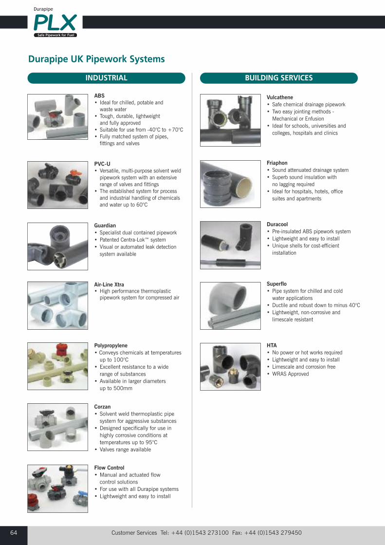
Customer Services Tel: +44 (0)1543 273100 Fax: +44 (0)1543 27945064
Durapipe UK Pipework Systems
ABS• Ideal for chilled, potable and waste water
• Tough, durable, lightweight and fully approved
• Suitable for use from -40°C to +70°C• Fully matched system of pipes,fittings and valves
PVC-U• Versatile, multi-purpose solvent weldpipework system with an extensiverange of valves and fittings
• The established system for processand industrial handling of chemicalsand water up to 60°C
Guardian• Specialist dual contained pipework• Patented Centra-Lok™ system• Visual or automated leak detectionsystem available
Flow Control• Manual and actuated flow control solutions
• For use with all Durapipe systems• Lightweight and easy to install
Vulcathene• Safe chemical drainage pipework• Two easy jointing methods -Mechanical or Enfusion
• Ideal for schools, universities andcolleges, hospitals and clinics
Superflo• Pipe system for chilled and cold water applications
• Ductile and robust down to minus 40°C• Lightweight, non-corrosive and limescale resistant
Duracool• Pre-insulated ABS pipework system• Lightweight and easy to install• Unique shells for cost-efficientinstallation
HTA• No power or hot works required• Lightweight and easy to install• Limescale and corrosion free• WRAS Approved
Friaphon• Sound attenuated drainage system• Superb sound insulation with no lagging required
• Ideal for hospitals, hotels, officesuites and apartments
Corzan• Solvent weld thermoplastic pipesystem for aggressive substances
• Designed specifically for use inhighly corrosive conditions attemperatures up to 95°C
• Valves range available
Polypropylene • Conveys chemicals at temperaturesup to 100°C
• Excellent resistance to a widerange of substances
• Available in larger diameters up to 500mm
INDUSTRIAL BUILDING SERVICES
Air-Line Xtra • High performance thermoplasticpipework system for compressed air
Customer Services Tel: +44 (0)1543 273100 Fax: +44 (0)1543 27945066
Notes
email: [email protected] web: www.plxpipe.com 67
1. DEFINITIONS:‘Seller’ shall mean Glynwed Pipe Systems Limited, registered in England under number1698059. ‘Buyer’ shall mean any company, organisation or individual to whom a quotationis offered, or whose order is accepted by the Seller.
2. CONDITIONS:All offers, quotations, estimates, acceptances and contracts are subject to these Conditionsof Business and any terms or conditions which any other person shall seek to impose ormake part of any contract shall, so far as is inconsistent with these Conditions of Business,not apply unless expressly agreed by the Seller in writing. The headings in these conditionsare for convenience only and shall not affect their interpretation.
3. QUOTATIONS AND PRICE VARIATION:a) Any quotation given by the Seller is an invitation to the Buyer to make an offer only andno order of the Buyer placed with the Seller in pursuance of a quotation or otherwise shallbe binding on the Seller unless and until it is accepted in writing by the Seller.
b) Unless stated otherwise, all quotations and published price lists are ex works, exclusiveof VAT and shall remain valid for 30 days or such a period as may be quoted butnevertheless the Seller may amend or withdraw any quotation by written or oral notice.Quotations may be varied if the Buyer makes variations in his specifications.
4. STATEMENTS OR REPRESENTATIONS TO THE BUYER:If any statement or representation has been made to the Buyer upon which the Buyer reliesother than in the documents enclosed with the Seller's quotation, the Buyer must set outthat statement or representation in a document to be attached to or endorsed on the orderin which case the Seller may submit a new quotation.
5. DELIVERY - TIME:a) Any period for delivery given at any time and in any manner by the Seller is an estimateonly and is not binding on the Seller. Delivery periods are normally calculated from the laterof:
i) acceptance of order; or
ii) where applicable, the receipt by the Seller of a detailed specification or drawings.
b) Time shall not be deemed to be of the essence of the contract. Failure by the Seller tomeet any quoted delivery period for any part or the whole of the order shall not entitle theBuyer to rescind the contract or to claim damages of any nature.
c) The Seller will endeavour to comply with reasonable requests by the Buyer forpostponement of delivery but shall be under no obligation to do so. Where delivery ispostponed otherwise than due to default by the Seller the Buyer shall pay all costs andexpenses including a reasonable charge for storage and transportation occasioned therebyand an extra charge for split delivery if applicable.
d) The Buyer will receive delivery of any consignment between the hours of 8.00am and4.00pm Monday to Friday inclusive, unless otherwise agreed in writing. Cost incurred bythe Seller arising from the Buyer's refusal to accept consignments within the agreed hoursshall be borne by the Buyer.
6. DELIVERY AND RISK:a) Except where stated to the contrary in the contract, delivery shall be made as follows:
i) where the Buyer provides the transport, delivery shall be made ex the Seller's works;
ii) where the Seller provides the transport, delivery shall be made to the premises of the Buyer, or the premises of the Buyer's customer or works site if the Buyer has requested delivery to be so made but where the Buyer has made such a request the Seller will make a first delivery to the Buyer's customer or works site as so much of the goods as is available for that delivery but subsequent deliveries will be made to the premises of the Buyer.
b) The Seller may at its discretion make partial delivery of orders and invoice the same.
c) Risk in the goods shall pass on delivery.
d) Where goods are sent FOB the Seller's responsibility shall cease when the goods areplaced on board ship or aircraft without the need for the Seller to give notice to the Buyerand the provisions of Section 32(3) of the Sale of Goods Act 1979 shall not apply.
7. OWNERSHIP OF GOODS:a) The goods shall remain the sole and absolute property of the Seller as legal and equitableowner until such time as the Buyer shall have paid to the Seller the contract price togetherwith the full price of any other goods the subject of any contract between the Seller and theBuyer.
b) The Buyer acknowledges that until such time as the property in the goods passes to theBuyer he is in possession of the goods as a bailee and fiduciary agent for the Seller andthe Purchaser shall store the goods in such a manner that they are clearly identifiable asthe property of the Seller.
c) Until payment due under all contracts between the Buyer and the Seller had been madein full, in the event of sale of the goods by the Buyer:
i) the Seller shall be entitled to trace all proceeds of sale received by the Buyer through any bank or other account maintained by the Buyer; and
ii) the Buyer shall if requested by the Seller in writing to so assign its rights to recover the selling price of the goods from the third parties concerned. Such monies to be held separately by the Buyer as agent on behalf of the Seller.
d) The Seller may for the purpose of recovery of its goods enter upon any premises wherethey are stored or where they are reasonably thought to be stored and may repossess thesame.
8. TERMS OF PAYMENT:In the event of default in payment according to the agreed payment terms between theSeller and the Buyer – ie: by the end of the month following the month of despatch of thegoods the Seller shall be entitled without prejudice to any other right or remedy to suspendall further deliveries and to charge interest on any amount outstanding at the rate of 2% permonth until payment in full is made (a part of a month being treated as a full month for thepurpose of calculating interest).
9. SHORTAGES AND DEFECTS APPARENT ON DELIVERY:a) It shall be the responsibility of the Buyer to inspect or arrange for an inspection of thegoods on delivery whether the goods are delivered to the Buyer's premises or to thepremises of the Buyer's customer or to a works site. If no such inspection is made the Buyershall be deemed to have accepted the goods.
b) The Buyer shall have no claim for shortages or defects apparent on inspection unless:
i) a written complaint is made to the Seller within three days of receipt of the goods specifying the shortage or defect; and
ii) the Seller is within seven days of receipt of the complaint given an opportunity to inspect the goods and investigate the complaint before any use is made of the goods.
c) If a complaint is not made to the Seller as herein provided then in respect of suchshortages or defects the goods shall be deemed to be in all respects in accordance withthe contract and the Buyer shall be bound to pay for the same accordingly.
10. CLAIMS FOR DEFECTS NOT APPARENT ON INSPECTION:a) The Buyer shall have no claim for defects not apparent on inspection unless the Selleris notified of defective workmanship or materials within twelve months from delivery of thegoods. Provided that the goods have been installed and applied in accordance with anyrelevant recommendations made by the Seller, the Seller will at its option replace the goodsor refund the net invoiced price in respect of the goods which have been shown to bedefective. If the Seller does so supply substitute goods the Buyer shall be bound to acceptsuch substituted goods in full satisfaction of the obligations of the Seller under the contract.
b) The Buyer shall in any event have no claim or set-off in respect of defects unless a writtencomplaint is sent to the Seller as soon as the defect is noticed and no use is made of thegoods thereafter or alteration made thereto by the Buyer before the Seller is given anopportunity to inspect the goods.
c) The Buyer is responsible for ensuring that the goods are fit for any particular purpose,and no warranty or condition of fitness for any particular purpose is to be implied into thecontract.
11. LIABILITY:Save as stated in Conditions 9 and 10 (and save in respect of death or personal injuryresulting from the negligence of the Seller its servants or agents) the Seller shall not beliable for any claim or claims for direct or indirect consequential or incidental injury loss ordamage made by the Buyer against the Seller whether in contract or in tort (includingnegligence on the part of the Seller its servants or agents) arising out of or in connectionwith any defect in the goods or their fitness or otherwise for any particular purpose or anyact omission neglect or default of the Seller its servants or agents in the performance of thecontract.
12. FORCE MAJEURE:Notwithstanding anything herein contained neither the Buyer nor the Seller is to be heldliable for any delay or failure to carry out the contract due wholly or in part to an act of Godaction by any Government whether British or foreign civil war strikes and/or lockoutswheresoever occurring fire trade disputes floods or unfavourable weather or any materialbecoming unavailable or irreplaceable (whether at all or at commercially acceptable prices)or any other circumstances beyond the control of the Seller.
13. SUB-CONTRACTING:The Seller reserves the right to sub-contract the fulfilment of any order or any part thereof.
14. INSOLVENCY AND BREACH OF CONTRACT:In the event that:
a) the Buyer commits any breach of the contract and fails to remedy such breach (if capable of remedy) within a period of thirty days from receipt of a notice in writing fromthe Seller requesting such remedy; or
b) any distress or execution is levied upon any of the goods or property of the Buyer; or
c) the Buyer offers to make any arrangements with or for the benefit of its creditors or (if an individual) becomes subject to a petition for a bankruptcy order or (being a limitedcompany) has a receiver appointed of the whole or any part of its undertaking property orassets; or
d) an order is made or a resolution is passed or analogous proceedings are taken for thewinding up of the Buyer (save for the purpose of reconstruction or amalgamation withinsolvency and previously approved in writing by the Seller) the Seller shall thereupon beentitled without prejudice to its other rights hereunder forthwith to suspend all furtherdeliveries until the default has been made good or to determine the contract and anyunfulfilled part thereof or at the Seller's option to make partial deliveries. Notwithstandingany such termination the Buyer shall pay to the Seller at the contract rate for all the goodsdelivered up to and including the date of termination.
15. INDUSTRIAL PROPERTY RIGHTS:If goods supplied by the Seller to the Buyer's design or specifications infringe or are allegedto infringe any patent or registered design right or copyright the Buyer will indemnify theSeller against all damages, costs and expenses incurred by the Seller as a result of theinfringement or allegation. The Buyer will give the Seller all possible help in meeting anyinfringement claim brought against the Seller.
16. BUYER'S ERROR IN ORDERING:In the event the Buyer orders incorrectly the Seller will be under no obligation to the Buyerto rectify or assist in rectifying the error.
17. LAW AND JURISDICTION:The contract shall be subject in all respects to English Law and to the jurisdiction of theEnglish Courts.
DURAPIPE UK CONDITIONS OF SALE
Customer Services Tel: +44 (0)1543 273100 Fax: +44 (0)1543 2794502
Durapipe PLX is a brand from Durapipe UK. Durapipe UK has been at the forefront of thermoplasticpipework technology for over half a century. Our pipes, fittings and valves are widely used in a variety ofindustrial applications around the world.
Manufacturing a wide range of market leading pipework systems for the conveyance of different media,Durapipe systems perform in the most demanding environments.
Durapipe PLX pipework systems have been specially developed for conveying liquid fuels, and are widelyused in service stations, commercial and industrial fuelling applications around the world.
Drivers of commercial and private vehiclesneed fuel to be easily accessible, makingthe forecourt a necessity of daily life. PLX pipework ensures that fuel istransferred safely from tanks to dispensers.
With an increased reliance on electronicsystems in everyday life, sudden loss ofelectricity can endanger lives and disruptbusiness services and commerce.Uninterrupted Power Supply (UPS) systemssafeguard against this scenario which relieson emergency generators. These in turn needa reliable pipework system for their fuelsupply. PLX pipework meets this need.
All modes of transport require fuel toenable them to function as required.Marinas, airports, railway stations andhaulage distribution depots all need fuel.Specialist pipe systems are required tomeet the needs of these refuelling depots. PLX pipework meets these needs.
Forecourts
Power Supply
Transport Refuelling
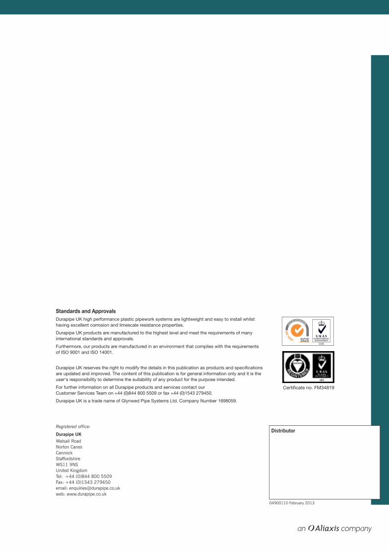
Technical Guide
Standards and ApprovalsDurapipe UK high performance plastic pipework systems are lightweight and easy to install whilsthaving excellent corrosion and limescale resistance properties.
Durapipe UK products are manufactured to the highest level and meet the requirements of manyinternational standards and approvals.
Furthermore, our products are manufactured in an environment that complies with the requirementsof ISO 9001 and ISO 14001.
Durapipe UK reserves the right to modify the details in this publication as products and specificationsare updated and improved. The content of this publication is for general information only and it is theuser's responsibility to determine the suitability of any product for the purpose intended.
For further information on all Durapipe products and services contact our Customer Services Team on +44 (0)844 800 5509 or fax +44 (0)1543 279450.
Durapipe UK is a trade name of Glynwed Pipe Systems Ltd. Company Number 1698059.
Certificate no. FM34819
Distributor
04900110 February 2013
Registered office:
Durapipe UKWalsall Road Norton CanesCannockStaffordshireWS11 9NSUnited Kingdom Tel: +44 (0)844 800 5509Fax: +44 (0)1543 279450email: [email protected]: www.durapipe.co.uk
PLX TEC
HN
ICA
L GU
IDE
FEBR
UA
RY 2013


![Plx 717 2011[1]](https://img.pdfslide.net/doc/110x75/54603047b1af9ffa588b51d4/plx-717-20111.jpg)