Embed Size (px)
Citation preview
Clays and Clay Minerals, Vol. 34, No. 1, 53-68, 1986.
POLYTYPISM OF MICAS. III. X-RAY DIFFRACTION IDENTIFICATION
Z. WEISS
Coal Research Institute, 716 07 Ostrava-Radvanice Czechoslovakia
A. WIEWIORA
Institute of Geological Sciences, Polish Academy of Sciences 02 089 Warszawa, Poland
Abstract--Classification and identification criteria of maximum-degree-of-order (MDO) polytypes of homo- and meso-octahedral micas based on the distribution of the intensities of 201 (13l) and 021 reflections are proposed. Calculated IF(20/)[ 2 and [F(02I)[ 2 values for single crystals of micas with different compositions are given for one-, two-, and three-layer polytypes. Transmission powder diffrac- tometry is proposed as a suitable method for the identification of the different groups of mica polytypes from polycrystalline specimens. Calculated powder patterns and the characteristic properties of the dif- fraction patterns of random and highly oriented aggregates are employed for identification purposes. The individual MDO polytypes are designated by generalized Ramsdell symbols which also contain infor- mation about their position in the classification system. Key Words--Crystal structure, Mica, Order-disorder, Polytype, Single crystal X-ray diffraction, X-ray powder diffraction.
Resiimee--Klassifikations und Identifikationskriterien f'tir alle maximaler Ordnungsgrad (MOG) Polytype yon homo- und meso-oktaedrischen Glimmern, die auf den Intensit~tenverteilungen yon 20l (13l) und 02l Reflexen beruhen, wurden ausgearbeitet. Die berechneten [ F(201) [ 2 und I F(02l)l 2 Werte f'tir Glim- mereinkristalle mit variabler Zusammensetzung und f'tir alle Ein-, Zwei-, und Dreischicht-Polytypen sind angefiihrt. Als geeignete Methode zur Identifikation yon verschiedenen Glimmergruppen in ihren poly- kristallinen Proben ist Transmissions-Diffraktometrie vorgeschlagen. Der Artikel enth/tlt auch berechnete Pulverdiagramme und ihre Identifikations-charakteristische Eigenschaften filr sowohl statistisch- als auch hochorientierte Aggregate. Die einzelnen MOG Polytype sind gekennzeichnet durch verallgemeinerte Ramsdellsche Symbole, die auch Information fiber ihre Stellung in dem Klassifikationssystem enthalten.
I N T R O D U C T I O N
In a recent publication (I)urovi~ et al., 1984) a clas- sification system for mica polytypes was presented. This system is based on an order-disorder (OD) model of mica structures with ideal ditrigonalization of their tet- rahedral sheets--the so-called Radoslovich model (Backhaus and I)urovir, 1984). It is closely related to characteristic properties of X-ray diffraction patterns of individual mica polytypes because it is based on the following fundamental geometrical characteristics of their structures:
(1) Superposition structure--defined according to the OD theory as a hypothetical structure in which all pos- sible positions of all OD layers are realized simulta- neously (cf. Backhaus and Durovir, 1984). It is by definition three-dimensionally periodic, and, because its basic vector B in micas is b/3, it corresponds to sharp reflections with k = 3n (orthogonal indexing). All mica polytypes belonging to the same family (i.e,, that have the same chemical composition and symmetry of their octahedral sheets) in which all the interlayer cat-
Copyright �9 1986, The Clay Minerals Society
ions are octahedrally coordinated, have the same su- perposition structure and are said to belong to subfam- ily A. Thei r fully descr ip t ive polytype symbols (Dornberger-Schiff et al., 1982) contain orientational characters, all of the same parity. The remaining poly- types of the family have all their interlayer cations in a trigonal prismatic coordination and are said to belong to subfamily B. The parity of orientational characters related to individual mica layers in their structures regularly alternates. An analogous parity rule holds also for the characters in the corresponding symbols pro- posed by Ross et al. (1966) in that only even-numbered characters apply to subfamily A and only odd-num- bered characters apply to subfamily B. It follows that the X-ray diffraction patterns of all polytypes of the same subfamily have the same characteristic subset of sharp reflections with k = 3n and the same X Z pro- jection of their structures.
(2) YZ projection o f the structure. --All polytypes of the same family which have the same Y Z projection have also the same set of the Ok/reflections in their
53
54 Weiss and Wiewi6ra Clays and Clay Minerals
X-ray diffraction patterns. These reflections (except k = 3n) are sharp only for periodic polytypes; for non-per- iodic polytypes they appear as diffuse streaks, or they may be smeared-out completely.
From the geometrical considerations it follows that these two characteristics suffice to characterize un- ambiguously any polytype. Thus, it is necessary only to inspect reflections with k = 3n to identify the subfamily and then the reflections Ok/(k # 3n) to de- termine the polytype within it. It is the aim of the present paper to describe in detail how this can be done.
Reflections with k = 3n are sharp for all members of a subfamily, regardless of whether they are periodic (ordered) or non-periodic (disordered). Thus, the subfamily can always be determined. On the other hand, any periodic member has its own Y Z projection and consequently its own characteristic set of Ok/(k # 3n) reflections. Of a theoretically infinite number of pe- riodic polytypes from a given subfamily, however, only the polytypes with max imum degree of order (MDO) will be dealt with in this paper. These are the polytypes containing the smallest possible number of kinds of triples, quadruples etc. of OD layers (for their deri- vation in micas, see Backhaus and I)urovir, 1984) and, as shown by f)urovi~ et aL (1984) they are most fre- quently encountered in natural and synthetic micas.
The three octahedral positions M(1), M(2), and M(3) in the octahedral sheet of a mica polytype can be oc- cupied in different ways. I f all positions are occupied by the same cation, one speaks of a homo-octahedral family (commonly containing trioctahedral polytypes), and 6 non-equivalent MDO polytypes exist for it. I f two sites are occupied by the same cation and the third by a different cation, a meso-octahedral family results (if the third position is a void, dioctahedral polytypes result), and 14 non-equivalent MDO polytypes exist for it. Finally, i f all three sites are occupied by three different cations in an ordered manner, a hetero-oc- tahedral family with 36 non-equivalent M D O poly- types results.
The three octahedral positions can be occupied in the meso-octahedral family in three, and in the hetero- octahedral family, in six different ways. Thus, three meso-octahedral and six hetero-octahedral polytypes can, in general, be assigned to one homo-octahedral polytype. All these polytypes have the same framework of all atoms except those that are octahedrally coor- dinated, which have similar basic vectors. Their X-ray diffraction patterns are also closer to one another than to those of other polytypes. These relations have been called the relations o f homomorphy .
All M D O polytypes of a family which have the same Y Z projection are said to belong to the same M D O group. Five, eleven, and thirty MDO groups exist for homo-, meso-, and hetero-octahedral micas, respec- tively. Their homomorphic relations are shown in Ta-
ble 4 of I)urovi6 et al. (1984) and are useful when identifying polytypes.
GENERALIZED RAMSDELL N O T A T I O N
The relations ofhomomorphy indicate that the three meso- octahedraland the six hetero-octahedralmica polytypes related to one homo-octahedral family, may have the same number of layers per identity period. They commonly belong to the same crystal system and thus they may have the same Rams- dell symbol. It is, of course, possible to distinguish between them by using their respective fully descriptive polytype sym- bols. This distinction may not always be practical, and hence it may be advantageous to generalize the popular and widely used Ramsdell symbols, not just by formal subscripts but by identifiers which convey the position of a polytype in the classification system and the relations of homomorphy.
Table 1 is a "cross-reference" classification table for homo- and meso-octahedral mica polytypes. This table differs from Table 4 of Durovi6 et al. (1984) not only by its deletion of the hetero-octahedral polytypes but also by its inclusion of the new indicative symbols for the polytypes. As shown in the table, the traditional Ramsdell symbols are combined with the present classification on the basis of the two fundamental structural characteristics mentioned above. The table there- fore provides unambiguous polytype designations which are more informative than the traditional symbols alone.
The new notation (valid for all phyllosilicates) consists, as a rule, of three identifiers: The first identifier corresponds essentially to the traditional Ramsdell symbol indicating the number of layers and the crystal class (A = triclinic (anorthic),l M = monoclinic, O = orthorhombic, T = trigonal, H = hex- agonal, R = rhombohedral). The second is a subscript de- noting the subfamily, e.g., 2MA, 2MB instead of 2M~, 2M2 used presently. The third, following the hyphen (-), stands for the appropriate MDO group. One, two, or three numbers may be present, separated by commas (,) for homo-, meso-, and hetero-octahedral families, respectively. The MDO groups in the homo-octahedral family are labelled by roman, and others by arabic numerals; e.g., 1M^-I, 1 denotes a one-layer mon- oclinic polytype belonging to the subfamily A and the meso- octahedral MDO group 1 homomorphous to the homo-oc- tahedral group I, that is, the polytype with fully descriptive symbol 13.3 I.
The first two identifiers are also meaningful for non-MDO periodic polytypes. Most of these polytypes (Baronnet et aL, 1981) belong to subfamily A, and thus the symbols have the form: 3MA, 3AA, 8MA, etc. For highly unprobable polytypes in which both subfamilies intermix, only the first identifiers identical with the traditional Ramsdell symbol can be used. The symbol should also be reduced if diffuse streaks preclude determination of the MDO groups and number of layers by X-ray diffraction methods, but the subfamily can be deter- mined. Such samples should be described merely as a dis- ordered mica polytype of the subfamily A or B. With few exceptions, only these generalized Ramsdell symbols will be used in this paper. The corresponding fully descriptive sym- bols can be found using Table 1 of the present paper, Table 4 of I)urovi6 et al. (1984), and Tables 7 and 9 of Backhaus and l)urovi6 (1984).
1 These abbreviations are in keeping with the recent rec- ommendation of the Ad hoc Committee on the Nomenclature of Disordered, Modulated and Polytype Structures of the In- ternational Union of Crystallography (Guinier et al., 1984).
Vol. 34, No. 1, 1986 Polytypism of micas
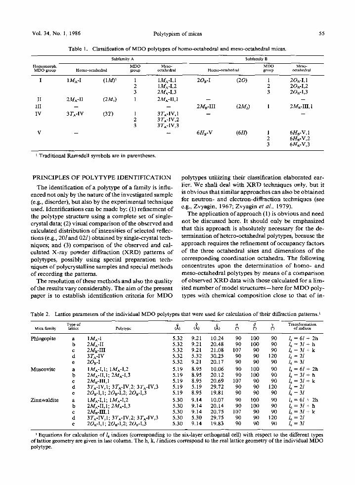
Table 1. Classification of MDO polytypes of homo-octahedral and meso-octahedral micas.
55
Subfamily A Subfamily B
Homomorph. MDO Meso- MDO Meso- MDO group Homo-octahedral group octahedral Homo-octahedral group octahedral
I 1MA-I (1M) 1 1 1MA-I,1 2OB-I (20) 1 2On-I, 1 2 1MA-I,2 2 2OB-I,2 3 2MA-I,3 3 2OB-I,3
II 2MA-II (2M1) 1 2MA-II, 1 -- III -- -- 2MB-III (2M2) 1 2MB-III, 1 IV 3TA-IV (37") 1 3TA-IV, 1 --
2 3 TA-IV,2 3 3TA-IV,3
V -- -- 6Hn-V (6H) 1 6HB-V,1 2 6HB-V,2 3 6Hn-V,3
Traditional Ramsdell symbols are in parentheses.
P R I N C I P L E S O F P O L Y T Y P E I D E N T I F I C A T I O N
The ident if icat ion o f a polytype o f a fami ly is influ- enced not only by the nature o f the invest igated sample (e.g., disorder), but also by the exper imenta l t echnique used. Identif icat ions can be m a d e by: (1) re f inement o f the polytype structure using a comple te set o f single- crystal data; (2) visual compar i son o f the observed and calculated dis t r ibut ion o f intensi t ies o f selected reflec- t ions (e.g., 20l and 02l) ob ta ined by single-crystal tech- niques; and (3) compar i son o f the observed and cal- culated X-ray powder diffraction (XRD) pat terns o f polytypes, possibly using special prepara t ion tech- niques o f polycrystal l ine samples and special me thods o f recording the patterns.
The resolut ion o f these me thods and also the qual i ty o f the results va ry considerably. The a im o f the present paper is to establish ident i f icat ion cri teria for M D O
polytypes ut i l izing their classification e labora ted ear- lier. W e shall deal wi th X R D techniques only, bu t it is obv ious that s imi lar approaches can also be ob ta ined for neut ron- and electron-diffract ion techniques (see e.g., Zvyagin , 1967; Zvyag in et al., 1979).
The appl ica t ion o f approach (1) is obv ious and need not be discussed here. It should only be emphas i zed that this approach is absolutely necessary for the de- te rminat ion o f hetero-octahedral polytypes, because the approach requires the re f inement o f occupancy factors o f the three octahedra l sites and d imens ions o f the cor responding coord ina t ion octahedra . The fol lowing concentra tes upon the de t e rmina t ion o f h o m o - and meso-oc tahedra l polytypes by means o f a compa r i son o f observed X R D data wi th those calculated for a l im- i ted n u m b e r o f m o d e l s t ruc tu res - -he re for M D O poly- types wi th chemica l compos i t i on close to that o f in-
Table 2. Lattice parameters of the individual MDO polytypes that were used for calculation of their diffraction patterns. 1
Type of b ~ V Transformation Mica family lattice Potytype (~,) (~,) (L (a.) (~ (*) of indices
Phlogopite a 1MA-I 5.32 9.21 10.24 90 100 90 16 = 6l + 2h b 2MA-II 5.32 9.21 20.48 90 100 90 16 = 3l + h c 2MB-III 5.32 9.21 21.08 107 90 90 /6 = 3l + k d 3TA-IV 5.32 5.32 30.25 90 90 120 16 = 2l e 2Oe-I 5.32 9.21 20.17 90 90 90 16 = 3l
Muscovite a 1MA-I,1; 1M^-I,2 5.19 8.95 10.06 90 100 90 16 = 6l + 2h b 2MA-II,1; 2MA-I,3 5.19 8.95 20.12 90 100 90 16 = 31 + h c 2MB-III,1 5.19 8.95 20.69 107 90 90 16 = 31 + k d 3TA-IV,1; 3TA-IV,2; 3TA-IV,3 5.19 5.19 29.72 90 90 120 16 = 2l e 2On-I,1; 2OB-I,2; 2OB-I,3 5.19 8.95 19.81 90 90 90 16 = 3l
Zinnwaldite a IM~,-I,1; 1MA-I,2 5.30 9.14 10.07 90 100 90 16 = 6l + 2h b 2MA-II,1; 2MA-I,3 5.30 9.14 20.14 90 100 90 /6 = 3l + h c 2MB-III, 1 5.30 9.14 20.75 107 90 90 16 = 3l + k d 3TA-IV,1; 3TA-IV,2; 3TA-IV,3 5.30 5.30 29.75 90 90 120 16 = 2l e 2On-I,1; 2OB-I,2; 2OB-I,3 5.30 9.14 19.83 90 90 90 /6 = 3l
Equations for calculation of/6 indices (corresponding to the six-layer orthogonal cell) with respect to the different types of lattice geometry are given in last column. The h, k, l indices correspond to the real lattice geometry of the individual MDO polytype.
56 Weiss and Wiewi6ra Clays and Clay Minerals
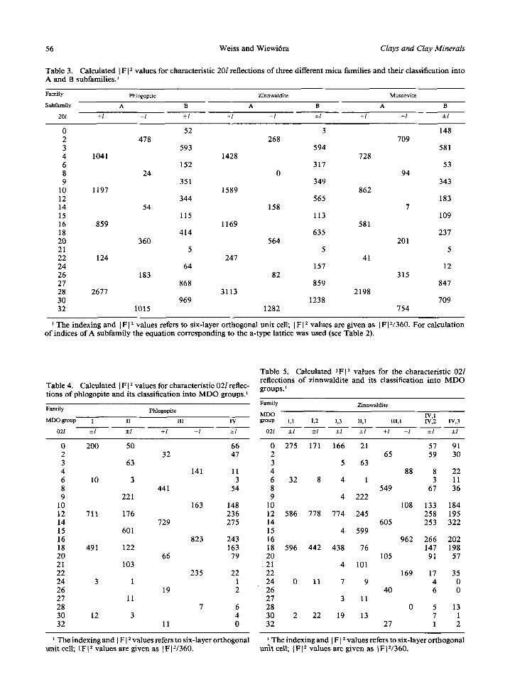
Table 3. Calculated I F 12 values for characterist ic 20l reflections o f three different mica famil ies and their classification into A and B subfami l i e s )
Family Phlogopite Zinnwaldite Muscovite
Subfamily A B A B A B
201 +/ - I • +l -1 • +1 -1 --.l
0 52 3 148 2 478 268 709 3 593 594 581 4 1041 1428 728 6 152 317 53 8 24 0 94 9 351 349 343
10 1197 1589 862 12 344 565 183 14 54 158 7 15 115 113 109 16 859 1169 581 18 414 635 237 20 360 564 201 21 5 5 5 22 124 247 41 24 64 157 12 26 183 82 315 27 868 859 847 28 2677 3113 2198 30 969 1238 709 32 1015 1282 754
1 The indexing and I FI 2 values refers to six-layer or thogonal un i t cell; I FI 2 va lues are g iven as IF IV360. For calculat ion o f indices o f A subfami ly the equa t ion cor responding to the a- type lattice was used (see Table 2).
Table 4. Calculated I F 12 values for characterist ic 021 reflec- t ions o f phlogopite and its classification into M D O groups, l
Family Phlogopite
MDO group I II III IV
02l • • +1 - I •
0 200 50 66 2 32 47 3 63 4 141 11 6 10 3 3 8 441 54 9 221
10 163 148 12 711 176 236 14 729 275 15 601 16 823 243 18 491 122 163 20 66 79 21 103 22 235 22 24 3 1 1 26 19 2 27 11 28 7 6 30 12 3 4 32 11 0
Table 5. Calculated IF[ 2 va lues for the characteris t ic 02l reflections o f z innwaldi te and its classification into M D O groups.
Family Zinnwaldite
MDO IV, 1 group 1,1 1,2 1,3 II, l III, l IV,2 IV,3
02l -+l +1 • • +l - I -+l +l
0 275 171 166 21 57 91 2 65 59 30 3 5 63 4 88 8 22 6 32 8 4 1 3 11 8 549 67 36 9 4 222
10 108 133 184 12 586 778 774 245 258 195 14 605 253 322 15 4 599 16 962 266 202 18 596 442 438 76 147 198 20 105 91 57 21 4 101 22 169 17 35 24 0 11 7 9 4 0 26 40 6 0 27 3 11 28 0 5 13 30 2 22 19 13 7 1 32 27 1 2
The indexing and I F [ 2 va lues refers to six-layer or thogonal ~ The indexing and I F [ z va lues refers to six-layer or thogonal un i t cell; IFI 2 va lues are g iven as IFI2/360. un i t cell; IFt 2 va lues are g iven as IF lV360.
Vol. 34, No. 1, 1986 Polytypism of micas 57
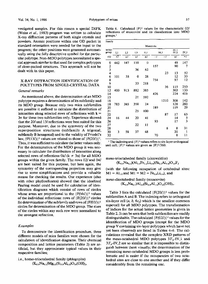
vestigated samples. For this reason a special DIFK (Weiss et al., 1983) program was written to calculate X-ray diffraction patterns of both single crystals and powders. Atomic positions within one OD packet in standard orientation were needed for the input to the program; the other positions were generated automat- ically using the fully descriptive symbol for the partic- ular polytype. Non-MDO polytypes necessitated a spe- cial approach similar to that used for complex polytypes of close-packed structures. This approach will not be dealt with in this paper.
X-RAY DIFFRACTION IDENTIFICATION OF POLYTYPES FROM SINGLE-CRYSTAL DATA
General remarks
As mentioned above, the determination of an MDO polytype requires a determination of its subfamily and its MDO group. Because only two mica subfamilies are possible it sufficed to calculate the distribution of intensities along selected rows of reflections with k = 3n for these two subfamilies only. Experience showed that the 20l and 131reflections were best suited for this purpose. Moreover, due to the symmetry of the two superpos i t ion s tructures ( subfami ly A tr igonal , subfamily B hexagonal) and to the validity of Friedel's law, I F(13l) 12 values are related to those of I F(201) 12. Thus, it was sufficient to calculate the latter values only. For the determination of the MDO group it was nec- essary to calculate the distribution of intensities along selected rows of reflections Ok/(k ~ 3n) for all MDO groups within the given family. The rows 02l and 041 are best suited for this purpose, but here again, the symmetry of the corresponding projection may give rise to some simplifications and provide a valuable means for checking the results. Our experience (also with other phyllosilicates) showed that the idealized Pauling model could be used for calculation of iden- tification diagrams which consist of rows of circles whose areas are proportional to the I F(hkl)l 2 values of the individual reflections: rows of IF(201) I e circles for determination of the subfamily and rows of I F(021) 12 circles for determination of the MDO group. The sizes of the circles within any such row were normalized to the strongest reflection.
Examples
To demonstrate the identification procedure, three different models of mica families were chosen for the calculation of identification diagrams. Their chemical composition and lattice parameters (Table 2) are ar- tificial, but they approximate typical values in their respective families;
i.e., homo-trioctahedral family (phlogopite) (Ko.9Nao.l)Mg3.o(Si3.oAll.0)01o(OH)2,
Table 6. Calculated I FI 2 values for the characteristic 02l reflections of muscovite and its classification into MDO groups.
Family
Mu~ovite
MDO IV, 1 ~oup 1,1 1,2 1,3 II,1 III,1 IV,2 IV,3
021 • • • • +l - I • •
0 442 147 110 0 49 147 2 157 90 7 3 36 62 4 23 13 52 6 101 35 0 28 12 33 8 754 97 12 9 33 218
10 36 115 253 12 400 913 882 385 303 133 14 426 224 405 15 21 592 16 1210 308 142 18 783 385 358 24 128 260 20 189 119 29 21 25 100 22 87 17 63 24 16 44 20 41 14 5 26 93 17 3 27 22 11 28 8 8 31 30 3 58 37 48 20 1 32 70 8 11
The indexing and I F 12 values refers to six-layer orthogonal unit cell; I FI 2 values are given as I FI 2/360.
meso-trioctahedral family (zinnwaldite) (Ko.gNao.~)(Alt.oFe~.2Li0.a)(Si3.2A10.a)O~oF2
(with the following occupation of octahedral sites: M1 = AILo and M1 = M2 = F e o . 6 t i o . 4 ) , and
meso-dioctahedral family (muscovite) (Ko.9Nao.,)Alu.o(Si3.oAll.0)01o(OH)2.
Table 3 lists the calculated [F(20I)I 2 values for the subfamilies A and B. The indexing refers to orthogonal six-layer cell (a, b, 6Co) which is the smallest common supercell for all MDO polytypes. The transformation of indices for the actual lattice geometries is given in Table 2. It can be seen that both subfamilies are readily distinguishable. The calculated ] F(02l) [ 2 values for the identification of MDO groups (except for the MDO group V containing six-layer polytypes which have not yet been observed) are listed in Tables 4-6. The cal- culations revealed that the complete X R D patterns of the meso-octahedral MDO polytypes 3TA-IV,1 and 3TA-IV,2 are so similar that it is impossible to distin- guish between them visually; the determination of the remaining meso-octahedral MDO groups is less prob- lematic and is easier if the occupancies of two octa- hedral sites are close to one another and if they differ considerably from the remaining one.
58 Weiss and Wiewi6ra Clays and Clay Minerals
I
0
2
z,
6
8
10
12
14
16
"/8
20
22
24
26
28
30
32
B 20_'1
ob5. cole.
,+ II1,1
02+1
obs. colc. 02-1
obs r
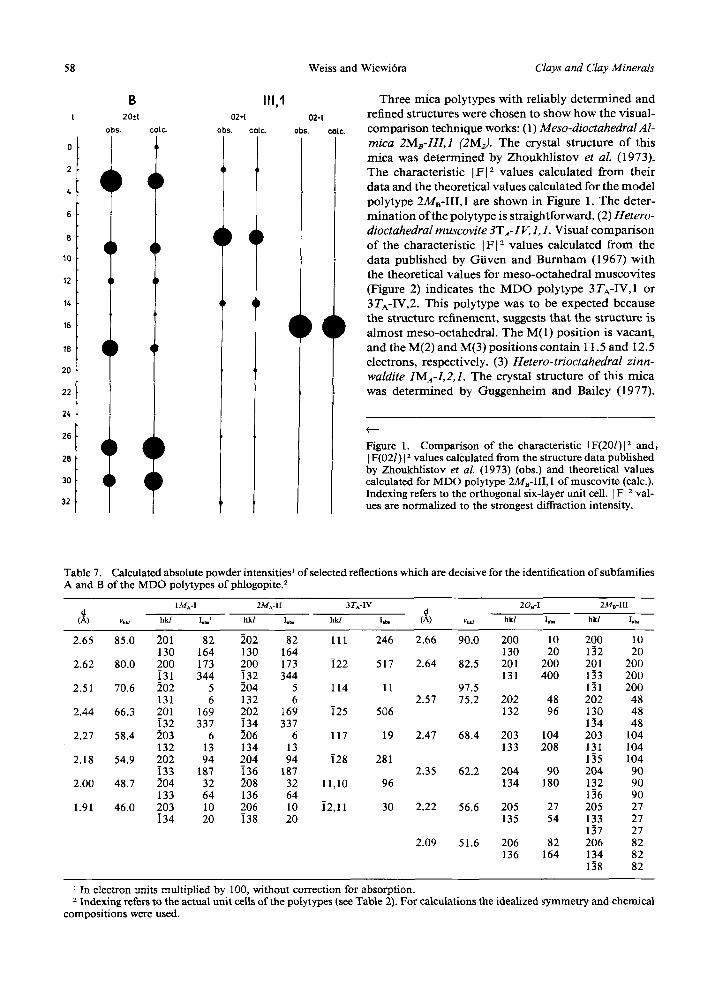
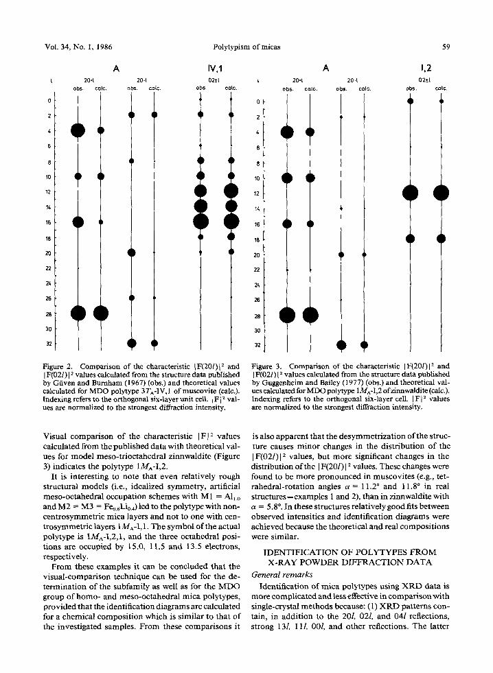
Three mica polytypes wi th rel iably de t e rmined and refined structures were chosen to show how the visual- compar i son technique works: (1) Meso-dioctahedral A l- mica 2MB-111,1 (2Mz). The crystal s tructure o f this mica was de t e rmined by Zhoukh l i s tov et aL (1973). The character is t ic I F I ~ values calculated f rom thei r data and the theoret ical va lues calculated for the m o d e l polytype 2MB-III, 1 are shown in Figure 1. The deter- mina t ion o f the polytype is s traightforward. (2) Hetero- dioctahedral muscovite 3T : IV, 1,1. Visual compa r i son o f the character is t ic IF[ ~ values calculated f rom the data publ i shed by Gi iven and B u r n h a m (1967) wi th the theoret ical values for meso-oc tahedra l muscov i t e s (Figure 2) indicates the M D O polytype 3 TA-IV, 1 or 3TA-IV,2. This polytype was to be expected because the structure ref inement , suggests tha t the s tructure is a lmos t meso-oc tahedra l . The M(1) posi t ion is vacant , and the M(2) and M(3) posi t ions conta in 11.5 and I2.5 electrons, respectively. (3) Hetero-trioctahedral zinn- waldite 1MA-I,2,1. The crystal s tructure o f this mica was de te rmined by Guggenhe im and Bailey (1977).
Figure l. Comparison of the characteristic [F(201)[ 2 and~ [ F(021)[ 2 values calculated from the structure data published by Zhoukhlistov et aL (1973) (obs.) and theoretical values calculated for MDO polytype 2MB-III, 1 of muscovite (calc.). Indexing refers to the orthogonal six-layer unit cell. ] F] 2 val- ues are normalized to the strongest diffraction intensity.
Table 7. Calculated absolute powder intensitiest of selected reflections which are decisive for the identification of subfamilies A and B of the MDO polytypes of phlogopite3
IMA-I 2M^-II 3TA-IV 2Oe-I 2Ma-III A d (~) v~ hkl I.b,' hkl I.b, hkl I,b, {~) u~ hkl I.b, hkl I,~
2.65 85.0 201 82 ]02 82 111 246 2.66 90.0 200 10 200 10 130 164 130 164 130 20 112 20
2.62 80.0 200 173 200 173 ]22 517 2.64 82.5 201 200 201 200 131 344 i32 344 131 400 133 200
2.51 70.6 ]02 5 ]04 5 114 11 97.5 131 200 131 6 132 6 2.57 75.2 202 48 202 48
2.44 66.3 201 169 202 169 125 506 132 96 130 48 [32 337 i34 337 114 48
2.27 58.4 203 6 206 6 117 19 2.47 68,4 203 104 203 104 132 13 134 13 133 208 131 104
2.18 54.9 202 94 204 94 i28 281 135 104 ]33 187 ]36 187 2.35 62.2 204 90 204 90
2.00 48.7 ]04 32 208 32 11,10 96 134 180 132 90 133 64 136 64 136 90
1.91 46.0 203 10 206 10 i2,11 30 2.22 56.6 205 27 205 27 i34 20 i38 20 135 54 133 27
137 27 2.09 51.6 206 82 206 82
136 164 134 82 138 82
In electron units multiplied by 100, without correction for absorption. 2 Indexing refers to the actual unit ceUs of the polytypes (see Table 2). For calculations the idealized symmetry and chemical
compositions were used.
Vol. 34, No. 1, 1986 Polytypism of micas 59
t
0
2
4
6
8
10
12
14
16
18
2O
22
24
26
28
30
32
20*1 obs. calc.
qD
A 20-1
obs. co(c.
IV,1 02*t
obs. calc.
t
28
30
32
qD
qD
qD
} q
A 1,2 20or 204 02._t
obs. cole. obs. cole. obs. cole.
T
i
q }
Figure 2. Comparison of the characteristic IF(20l){ 2 and [F(02/)I 2 values calculated from the structure data published by Gfiven and Burnham (1967) (obs.) and theoretical values calculated for MDO polytype 3 TA-1V, 1 of muscovite (cole.). Indexing refers to the orthogonal six-layer unit cell. L F [ 2 val- ues are normalized to the strongest diffraction intensity.
Figure 3. Comparison of the characteristic IF(20I)I 2 and IF(021) I 2 values calculated from the structure data published by Guggenheim and Bailey (I 977) (obs.) and theoretical val- ues calculated for MDO polytype 1MA-I,2 ofzinnwaldite (cole.). Indexing refers to the orthogonal six-layer cell. IF] : values are normalized to the strongest diffraction intensity.
Visual comparison of the characteristic IF[ : values calculated from the published data with theoretical val- ues for model meso-trioctahedral zinnwaldite (Figure 3) indicates the polytype 1MA-I,2.
It is interesting to note that even relatively rough structural models (i.e., idealized symmetry, artificial meso-octahedral occupation schemes with M 1 = All0 and M2 = M3 = Feo.rLi0.4) led to the polytype with non- centrosymmetric mica layers and not to one with cen- trosymmetric layers 1MA-I, 1. The symbol of the actual polytype is 1MA-I,2,1, and the three octahedral posi- tions are occupied by 15.0, 11.5 and 13.5 electrons, respectively.
From these examples it can be concluded that the visual-comparison technique can be used for the de- termination of the subfamily as well as for the MDO group of homo- and meso-octahedral mica polytypes, provided that the identification diagrams are calculated for a chemical composition which is similar to that of the investigated samples. From these comparisons it
is also apparent that the desymmetrization of the struc- ture causes minor changes in the distribution of the IF(02/)[ 2 values, but more significant changes in the distribution of the [ F(20I) [ 2 values. These changes were found to be more pronounced in muscovites (e.g., tet- rahedral-rotation angles a = 11.2 ~ and 11.8 ~ in real structures--examples 1 and 2), than in zinnwaldite with a = 5.8 ~ In these structures relatively good fits between observed intensities and identification diagrams were achieved because the theoretical and real compositions were similar.
IDENTIFICATION OF POLYTYPES FROM X-RAY POWDER DIFFRACTION DATA
General remarks
Identification of mica polytypes using XRD data is more complicated and less effective in comparison with single-crystal methods because: (1) XRD patterns con- tain, in addition to the 20/, 02/, and 04l reflections, strong 13/, 11/, 00/, and other reflections. The latter
60 Weiss and Wiewidra Clays and Clay Minerals
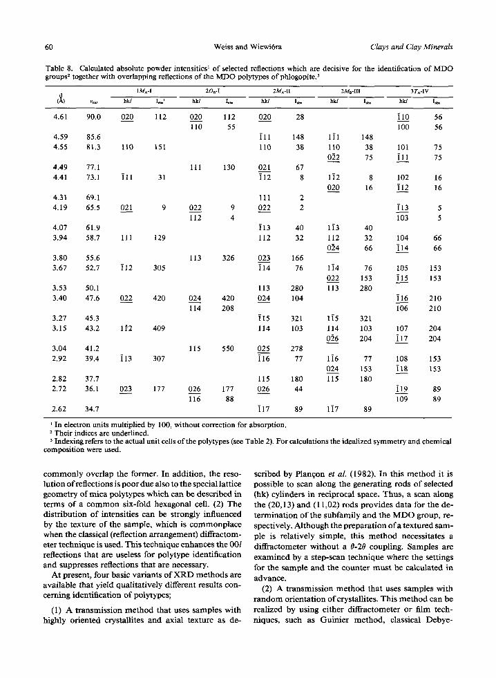
Table 8. Calculated absolute powder intensities I of selected reflections which are decisive for the identification of MDO groups 2 together with overlapping reflections of the MDO polytypes of phlogopite. 3
1 MA-I 20B-I 2MA-II 2MB-III 3 TA-IV t~ (~) vh~..t hkl I ~ t hkl I.~, hkl I.~ hk/ I.~ hkl I.t,.
4.61 90.0 020 112 020 112 020 28 i l 0 56 110 55 100 56
4.59 85.6 i l l 148 1]1 148 4.55 81.3 110 151 110 38 110 38 101 75
0]2 75 i l l 75 4.49 77.1 111 130 021 67 4.41 73.1 i l l 31 i12 8 1i2 8 102 16
020 16 i12 16 4.31 69.1 111 2 4.19 65.5 021 9 022 9 022 2 i13 5
112 4 103 5 4.07 61.9 i13 40 1i3 40 3.94 58.7 111 129 112 32 112 32 104 66
0]4 66 114 66 3.80 55.6 113 326 023 166 3.67 52.7 i12 305 114 76 1i4 76 105 153
022 153 i15 153 3.53 50.1 113 280 113 280 3.40 47.6 022 420 024 420 024 104 i16 210
114 208 106 210 3.27 45.3 i15 321 1i5 321 3.15 43.2 152 409 114 103 114 103 107 204
056 204 i17 204 3.04 41.2 115 550 025 278 2.92 39.4 i13 307 i16 77 1i6 77 108 153
024 153 i18 153 2.82 37.7 115 180 115 180 2.72 36.1 023 177 026 177 026 44 i19 89
116 88 109 89 2.62 34.7 i17 89 1i7 89
1 In electron units multiplied by 100, without correction for absorption. 2 Their indices are underlined. 3 Indexing refers to the actual unit cells of the polytypes (see Table 2). For calculations the idealized symmetry and chemical
composition were used.
commonly overlap the former. In addition, the reso- lution of reflections is poor due also to the special lattice geometry of mica polytypes which can be described in terms of a common six-fold hexagonal cell. (2) The distribution of intensities can be strongly influenced by the texture o f the sample, which is commonplace when the classical (reflection arrangement) diffractom- eter technique is used. This technique enhances the 001 reflections that are useless for polytype identification and suppresses reflections that are necessary.
At present, four basic variants o f X R D methods are available that yield qualitatively different results con- cerning identification of polytypes;
(1) A transmission method that uses samples with highly oriented crystallites and axial texture as de-
scribed by Plan~on et al. (1982). In this method it is possible to scan along the generating rods of selected (hk) cylinders in reciprocal space. Thus, a scan along the (20,13) and (11,02) rods provides data for the de- termination of the subfamily and the M D O group, re- spectively. Although the preparation o f a textured sam- pie is relatively simple, this method necessitates a diffractometer without a 0-20 coupling. Samples are
examined by a step-scan technique where the settings for the sample and the counter must be calculated in advance.
(2) A transmission method that uses samples with random orientation of crystallites. This method can be realized by using either diffractometer or film tech- niques, such as Guinier method, classical Debye-
Vol. 34, No. 1, 1986 Polytypism of micas 61
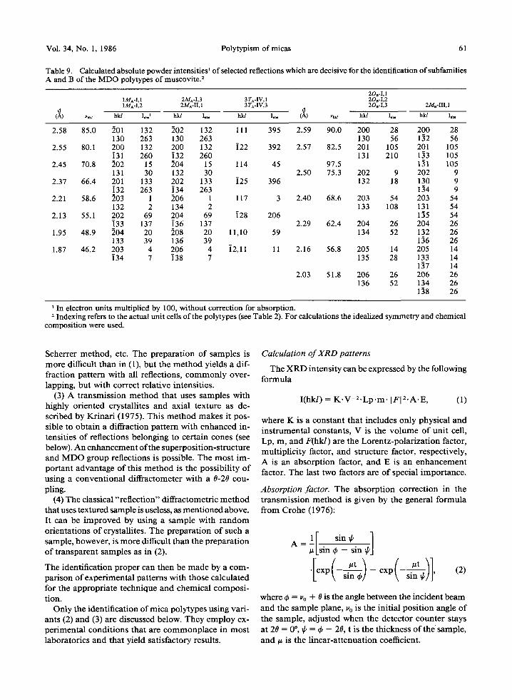
Table 9. Calculated absolute powder intensitiesl of selected reflections which are decisive for the identification of subfamilies A and B of the MDO polytypes of muscovite. 2
2Oa-I, 1 1MA-I, 1 2MA-I,3 3 TA-IV, 1 2Oa-I,2 1MA-I,2 2M^-II, 1 3 TA-IV,3 2OB-I,3 2Me-III , 1
d d (,~) Vma hkl Iob, x hkl I ~ hkl Io.~ (/~) vma hkl I..~ hkl I..~
2.58 85.0 201 132 202 132 111 395 2.59 90.0 200 28 200 28 130 263 130 263 130 56 132 56
2.55 80.1 200 132 200 132 i22 392 2.57 82.5 201 105 201 105 i31 260 132 260 131 210 133 105
2.45 70.8 ]02 15 204 15 114 45 97.5 131 105 131 30 132 30 2.50 75.3 202 9 202 9
2.37 66.4 201 133 202 133 i25 396 132 18 130 9 i32 263 i34 263 134 9
2.21 58.6 203 1 206 1 117 3 2.40 68.6 203 54 203 54 132 2 134 2 133 108 131 54
2.13 55.1 202 69 204 69 i28 206 135 54 i33 137 i36 137 2.29 62.4 204 26 204 26
1.95 48.9 ]04 20 ]08 20 11,10 59 134 52 132 26 133 39 136 39 136 26
1.87 46.2 203 4 206 4 32,11 11 2.16 56.8 205 14 205 14 334 7 i38 7 135 28 133 14
137 14 2.03 51.8 206 26 206 26
136 52 134 26 138 26
In electron units multiplied by 100, without correction for absorption. 2 Indexing refers to the actual unit cells of the polytypes (see Table 2). For calculations the idealized symmetry and chemical
composition were used.
Scherrer method, etc. The preparation of samples is more difficult than in (1), but the method yields a dif- fraction pattern with all reflections, commonly over- lapping, but with correct relative intensities.
(3) A transmission method that uses samples with highly oriented crystallites and axial texture as de- scribed by Krinari (1975). This method makes it pos- sible to obtain a diffraction pattern with enhanced in- tensities of reflections belonging to certain cones (see below). An enhancement of the superposition-structure and M D O group reflections is possible. The most im- portant advantage of this method is the possibility of using a conventional diffractometer with a 0-20 cou- pling.
(4) The classical "'reflection" diffractometric method that uses textured sample is useless, as mentioned above. It can be improved by using a sample with random orientations of crystallites. The preparation of such a sample, however, is more difficult than the preparation of transparent samples as in (2).
The identification proper can then be made by a com- parison of experimental patterns with those calculated for the appropriate technique and chemical composi- tion.
Only the identification of mica polytypes using vari- ants (2) and (3) are discussed below. They employ ex- perimental conditions that are commonplace in most laboratories and that yield satisfactory results.
Calculation of XRD patterns
The X R D intensity can be expressed by the following formula
I(hkl) = K . V - 2 - L p - m - IFI2.A.E, (1)
where K is a constant that includes only physical and instrumental constants, V is the volume of unit cell, Lp, m, and F(hkl) are the Lorentz-polarization factor, multiplicity factor, and structure factor, respectively, A is an absorption factor, and E is an enhancement factor. The last two factors are o f special importance.
Absorption factor. The absorption correction in the transmission method is given by the general formula from Crohe (1976):
#[s in ~b - sin
[exo(a) exo( (2)
where ~b = v0 + O is the angle between the incident beam
and the sample plane, v0 is the initial position angle of the sample, adjusted when the detector counter stays at 20 = 0", ~b = ~ - 20, t is the thickness of the sample, and # is the linear-attenuation coefficient.
62 Weiss and Wiewi6ra Clays and Clay Minerals
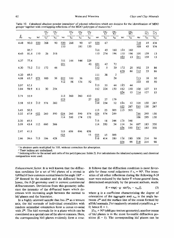
Table 10. Calculated absolute powder intensities ~ of selected reflections which are decisive for the identification of MDO groups 2 together with overlapping reflections of the MDO polytypes of muscovi te)
1MA- 1MA- 2OB- 2Oe- 2OB- 2MA- 2M^- 2MB- 3TA- 3T^- 1,1 1,2 1,1 1,2 1,3 1,3 II, 1 III, 1 IV, 1 1V,3
d (~) u~u hkl ][ , t I.b. hk/ I.~ I~. I.b, hk/ I.~. I ~ hk/ I.~ hk/ Ij~ (I.~
4.48 90.0 020 268 90 020 268 90 67 110 181 135
85.7 4.43 81.4 110 26 318
4.37 77.4 111 144 144 229 021 42
4.30 73.2 i l l 172 46
4.20 69.3 4.08 65.7 021 100 36 022 100 36
112 56 124 52 3.97 62.1 3.84 58.9 111 30 254
3.71 55.9 113 360 360 410 023 27
3.58 52.9 i12 574 260
3.45 50.3 3.32 47.9 022 260 590 024 260 590 574
114 510 174 132 3.20 45.5 3.09 43.4 112 660 366
2.97 41.5 115 606 606 636 025 15
2.86 39.6 i13 196 428
020 67 i l 0 45 134 100 45 134
]11 45 160 1]1 160 110 274 196 110 196 101 159 13
012 13 i l l 159 13
021 42 72 i12 5 20 1i2 20 102 23 86
020 86 i12 23 86 111 38 2 022 28 i13 18 50
103 18 50 i13 33 44 1[3 44 112 224 150 112 150 10~ 127 15
0~4 15 [14 127 15
023 27 179 i14 234 12 1i4 12 105 130 287
022 287 i15 130 287 113 23 303 113 303 024 574 249 i16 295 130
106 295 130 i15 18 348 115 348 114 350 34 114 34 107 183 330
026 330 i17 183 330
025 15 300 ]16 414 180 1i6 180 108 214 98
024 99 i18 214 98
In electron units multiplied by 100, without correction for absorption. 2 Their indices are underlined. 3 Indexing refers to the actual unit cells of the polytypes (see Table 2). For calculations the idealized symmetry and chemical
composition were used.
Enhancement factor. I t is well k n o w n t h a t the diffrac- t i on c o n d i t i o n for a set of h k / p l a n e s o f a crysta l is fulfilled i f t he i r c o m m o n n o r m a l bisects the angle 180 ~ - 20 ~ f o r m e d by the i nc iden t a n d the d i f f rac ted b e a m ; hence , the 0-20 geome t ry used in cu r r en t c o m m e r c i a l d i f f rac tometers . D e v i a t i o n s f r o m this g e o m e t r y influ- ence the in tens i ty o f the dif f racted b e a m w h i c h de- creases w i th inc reas ing angle be tween the n o r m a l to hk l p lanes a n d the bisectr ice.
In a h ighly o r i en t ed s a m p l e t h a t has Z* as a t ex ture axis, t he hk / n o r m a l s o f i n d i v i d u a l crysta l l i tes w i th r a n d o m a z i m u t h a l o r i e n t a t i o n fo rm a c o n u s co-ax ia l wi th Z*. T h e hk0 n o r m a l s lie in a p l ane wh ich can be c o n s i d e r e d as a special case o f the a b o v e conuses . Here , the c o r r e s p o n d i n g hk0 p lanes ev iden t ly f o r m a zone.
I t fol lows t h a t the d i f f rac t ion c o n d i t i o n is m o s t f avor - able for these zona l ref lec t ions i f vo = 90 ~ T h e i n t e n - si t ies o f all o t h e r ref lect ions du r ing the fo l lowing 0-20 scan were r educed by the fac tor E whose genera l fo rm, d e t e r m i n e d empi r i ca l ly b y the p re sen t au tho r s , reads:
E = e x p [ - g , sin2(vo - Vhkl)], (3)
whe re g is a coefficient cha rac t e r i z ing the degree o f o r i e n t a t i o n o f the aggregate a n d V~kl is the angle be- tween Z* a n d the surface l ine o f the c o n u s f o r m e d by all h k / n o r m a l s . F o r r a n d o m l y o r i e n t e d crystal l i tes , g = 0; hence E = 1.
Ifvo 4 : 9 0 ~ (ob l ique - t ex tu re geomet ry) , a n o t h e r c o n u s o f hk l p lanes is in the m o s t f avorab le d i f f rac t ion po- s i t ion (E = 1). T h e c o r r e s p o n d i n g h k l p lanes c an be
Vol. 34, No. 1, 1986 Polytypism of micas 63
i 0 0 I
80
i0
2O
0 0 ~0
100 I
BO
4O
20
0 0
IM A - I ; 3T A - IV
2O 3O 4O 5O 80
20 A - I
10 20 30 40 50 80
80
10
2O
0 10
X 2H 8 -III t00
80
40
2O
0 - 0 10 20 30 40 50 80
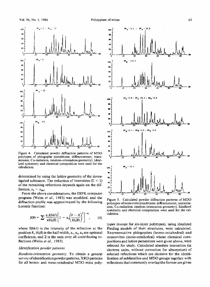
Figure 4. Calculated powder diffraction patterns of MDO polytypes of phlogopite (conditions: diffractometer, trans- mission, Cu-radiafion, random-orientation geometry). Ideal- ized symmetry and chemical composition were used for the calculation.
determined by using the lattice geometry of the inves- tigated substance. The reduction of intensities (E < 1) of the remaining reflections depends again on the dif- ference, Vo - Vhkl-
From the above considerations, the DIFK computer program (Weiss et al., 1983) was modified, and the diffraction profile was approximated by the following Lorentz function:
J(O) = ~ aJ(hll)[1 fo 0 i ~ 2 ] - a 3 1
7 F H i ( 0 ) L + a2~H-~-~- J J , (4)
where I(hk/) is the intensity of the reflection at the position 0i, Hi(0) is the half-width, a], a2, a3 are optional coefficients, and Z is the sum over all contributing re- flections (Weiss et al., 1983).
Identification powder patterns
Random-orientat ion geometry. To obtain a general survey o f identification powder patterns, X R D patterns for all homo- and meso-octahedral MDO mica poly-
104),
80 .
8 0 .
4 0 .
20
0
100
80
80
40
20
0
t N A - 1,1 ; 3T A - IV. 3
t 0 20 30 40 50 80
2N 8 - I I I , i
10 20 30 40 ~0 80
28
O'
i 0 0 ,
8 0 .
O0,
4 0 ,
ao i
0
t O
A N A - I , 2 ; 3 T A - I V , I ; ~ I A - I , 3
20 30 40 50 80
t0
2 0 B - L I ; 2 0 B - I . 2 ; 2 0 B - I . 3
20 30 40 50 80
100
80
80
40
20
0
~4 A - I L I
10 20 30 40 50 80
Figure 5. Calculated powder diffraction patterns of MDO polytypes of muscovite (conditions: diffractometer, transmis- sion, Cu-radiation, random-orientation geometry). Idealized symmetry and chemical composition were used for the cal- culation.
types (except for six-layer polytypes), using idealized Pauling models of their structures, were calculated. Representative phlogopites (homo-octahedral) and muscovites (meso-octahedral) whose chemical com- positions and lattice parameters were given above, were selected for study. Calculated absolute intensities (in electron units, without correction for absorption) of selected reflections which are decisive for the identi- fication of subfamilies and MDO groups together with reflections that commonly overlap the former are given
64 Weiss and Wiewi6ra Clays and Clay Minerals
ioo
BO
8 0
4O
20
0
ioo I
BO
40
2
0
I0
IW A - l , i
20 30 40 50 80
2N A - I I , i
iO 20 30 40 50 80
:'8
tO0,
aol
wol aol
tO0 .
ao i
ao i
4o i
2o i
oi
A iO
3T A - IV. i
20 30 40 50
%
2N B- l l I , i
20 30 40 50
N 80
60
tO0
aol 6oi
,oi
2 0
0
3T A - IV. I
6O
lO0
80
80
40
20
0
2N B - I I I , i
~0 20 30 40 50 80
28
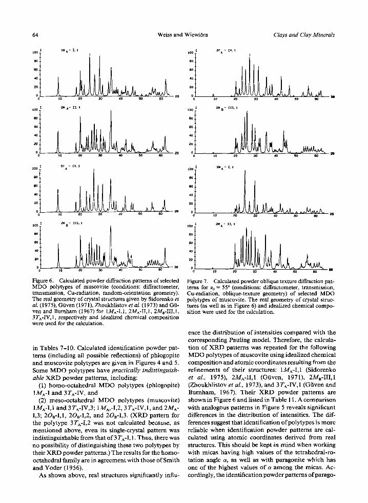
Figure 6. Calculated powder diffraction patterns of selected MDO polytypes of muscovite (conditions: diffractometer, transmission, Cu-radiation, random-orientation geometry). The real geometry of crystal structures given by Sidorenko et al. (1975), Giiven (1971), Zhoukhlistov et al. (1973) and Gii- yen and Burnham (1967) for 1MA-I,1, 2MA-II,1, 2Ma-III,1, 3TA-IV,1, respectively and idealized chemical composition were used for the calculation.
in Tables 7-10. Calculated identification powder pat- terns (including all possible reflections) of phlogopite and muscovite polytypes are given in Figures 4 and 5. Some M D O polytypes have practically indistinguish- able X R D powder patterns, including:
(1) homo-octahedral M D O polytypes (phlogopite) 1MA-I and 3TA-IV, and
(2) meso-octahedral M D O polytypes (muscovite) 1MA-I,1 and 3 TA-IV,3; 1MA,-I,2, 3 TA-IV, I, and 2MA- 1,3; 2OB-I,I, 2OB-I,2, and 2OB-I,3. (XRD pattern for the polytype 3TA-I,2 was not calculated because, as ment ioned above, even its single-crystal pat tern was indistinguishable from that o f 3 TA-I, 1. Thus, there was no possibility of distinguishing these two polytypes by their X R D powder patterns.) The results for the homo- octahedral family are in agreement with those of Smith and Yoder (1956).
As shown above, real structures significantly influ-
t O 0 ,
8 0 .
6 0 ,
2()
i N A - I , l
tO 20 30 40 50 BO
t00
80
80
40
20
0
2N A - I I , i
lO 20 30 40 50 80 m
Figure 7. Calculated powder oblique texture diffraction pat- terns for vo = 55* (conditions: diffractometer, transmission, Cu-radiation, oblique-texture geometry) of selected MDO polytypes of muscovite�9 The real geometry of crystal struc- tures (as well as in Figure 6) and idealized chemical compo- sition were used for the calculation.
ence the distr ibution of intensities compared with the corresponding Pauling model. Therefore, the calcula- t ion of X R D patterns was repeated for the following M D O polytypes of muscovite using idealized chemical composi t ion and atomic coordinates resulting from the refinements of their structures: 1MA-I,1 (Sidorenko et al., 1975), 2MA-II, I (Giiven, 1971), 2M,-III ,1 (Zhoukhlistov et al., 1973), and 3 TA-IV, 1 (Giiven and Burnham, 1967). Their X R D powder patterns are shown in Figure 6 and listed in Table 11. A comparison with analogous patterns in Figure 5 reveals significant differences in the distr ibution of intensities. The dif- ferences suggest that identification ofpolytypes is more reliable when identification powder patterns are cal- culated using a tomic coordinates derived from real structures. This should be kept in mind when working with micas having high values o f the tetrahedral-ro- ration angle a, as well as with paragonite which has one of the highest values o f a among the micas. Ac- cordingly, the identification powder patterns ofparago-
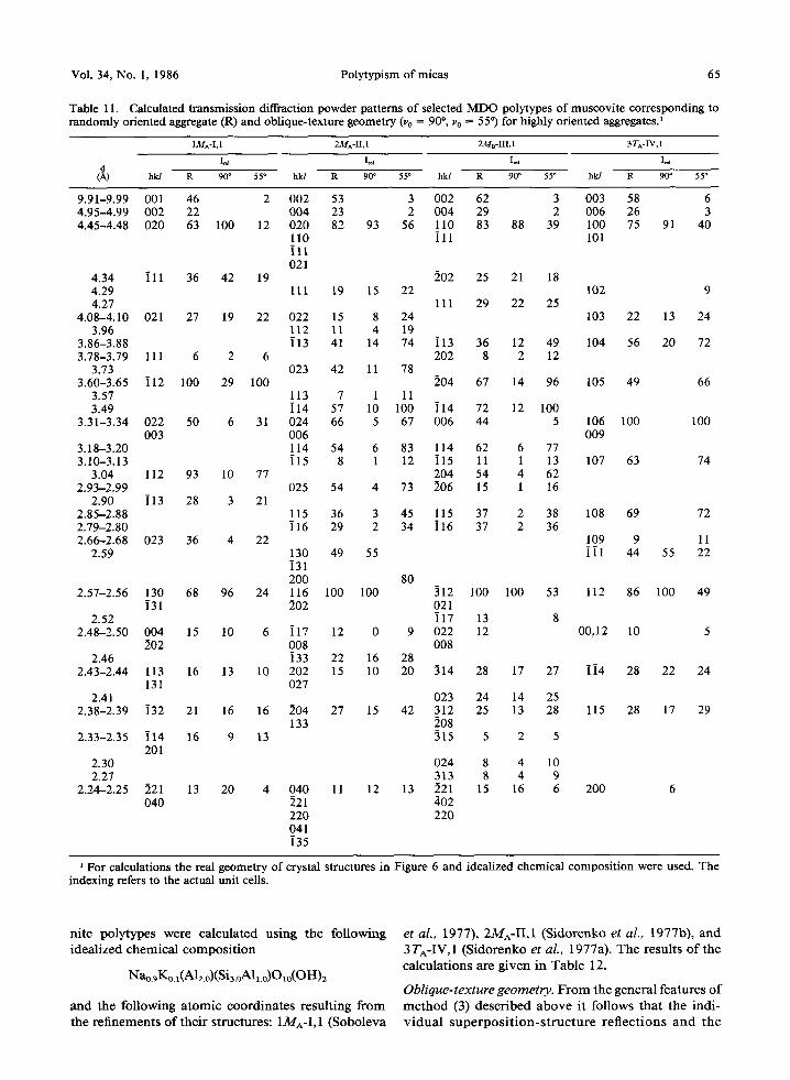
Vol. 34, No. 1, 1986 Polytypism of micas 65
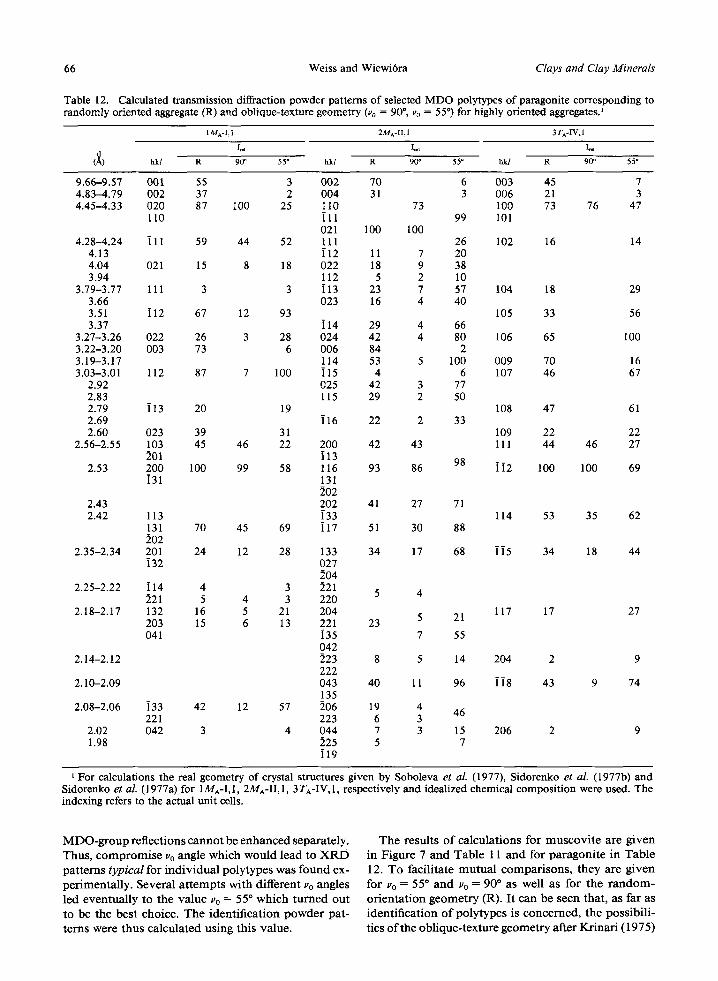
Table 11. Calculated transmission diffraction powder patterns of selected MDO polytypes of muscovite corresponding to randomly oriented aggregate (R) and oblique-texture geometry (Vo = 90 ~ Vo = 55*) for highly oriented aggregates. 1
1M^-I,1 2MA-II,1 2MB-III, I 3TA-IV,1
I~1 I,a I~a I~a d
(~k) hkl R 90* 55* hkl R 90* 55* hkl R 90* 55* hkl R 90* 55*
9.91-9.99 001 46 2 002 53 3 002 62 3 003 58 6 4.95--4.99 002 22 004 23 2 004 29 2 006 26 3 4.45-4.48 020 63 100 12 020 82 93 56 110 83 88 39 100 75 91 40
110 i l l 101 i l l 021
4.34 i l l 36 42 19 202 25 21 18 4.29 111 19 15 22 102 9 4.27 111 29 22 25
4.08--4.10 021 27 19 22 022 15 8 24 103 22 13 24 3.96 112 11 4 19
3.86-3.88 i13 41 14 74 i13 36 12 49 104 56 20 72 3.78-3.79 111 6 2 6 202 8 2 12
3.73 023 42 11 78 3.60-3.65 i12 100 29 100 204 67 14 96 105 49 66
3.57 113 7 1 11 3.49 i14 57 10 100 i14 72 12 100
3.31-3.34 022 50 6 31 024 66 5 67 006 44 5 106 100 100 003 006 009
3.18-3.20 114 54 6 83 114 62 6 77 3.10-3.13 i15 8 1 12 i15 11 1 13 107 63 74
3.04 112 93 10 77 204 54 4 62 2.93-2.99 025 54 4 73 206 15 1 16
2.90 i13 28 3 21 2.85-2.88 115 36 3 45 115 37 2 38 108 69 72 2.79-2.80 i16 29 2 34 i16 37 2 36 2.66-2.68 023 36 4 22 109 9 11
2.59 130 49 55 111 44 55 22 i31 200 80
2.57-2.56 130 68 96 24 116 100 100 312 100 100 53 112 86 100 49 i31 202 021
2.52 ]17 13 8 2.48-2.50 004 15 10 6 i17 12 0 9 022 12 00,12 10 5
202 008 008 2.46 ]33 22 16 28
2.43-2.44 113 16 13 10 202 15 10 20 314 28 17 27 i i 4 28 22 24 131 027
2.41 023 24 14 25 2.38-2.39 i32 21 16 16 204 27 15 42 312 25 13 28 115 28 17 29
133 208 2.33-2.35 i14 16 9 13 315 5 2 5
201 2.30 024 8 4 10 2.27 313 8 4 9
2.24-2.25 221 13 20 4 040 11 12 13 221 15 16 6 200 6 040 221 402
220 220 041 i35
1 For calculations the real geometry of crystal structures in Figure 6 and idealized chemical composition were used. The indexing refers to the actual unit cells.
n i te po ly types were ca lcu la ted us ing the fo l lowing idea l ized c h e m i c a l c o m p o s i t i o n
Nao.gKo.l(A12.o)(Si3.oAl~.o)O~o(OH)2
a n d the fol lowing a t o m i c coo r d i na t e s resu l t ing f r o m the r e f inemen t s o f t he i r s t ructures : 1MA-I, 1 (Sobo leva
et al., 1977), 2MA-II,1 (S ido renko et al., 1977b) , a n d 3TA-1V, 1 (S ido renko et aL, 1977a). T h e resu l t s o f the ca lcu la t ions are g iven in T a b l e 12.
Oblique-texture geometry. F r o m the genera l fea tures o f m e t h o d (3) desc r ibed a b o v e it fol lows t h a t the ind i - v i d u a l s u p e r p o s i t i o n - s t r u c t u r e r e f l e c t i o n s a n d t h e
66 Weiss and Wiewi6ra Clays and Clay Minerals
Table 12. Calculated transmission diffraction powder patterns of selected MDO polytypes of paragonite corresponding to randomly oriented aggregate (R) and oblique-texture geometry (~o = 90", vo = 55*) for highly oriented aggregates?
IMA-I, 1 2MA-II, 1 3 TA-IV, 1
I ~ I~l I ~ A
(X) hkl R 90* 55* hkl R 90* 55 ~ hk/ R 9(P 55*
9.66-9.57 001 55 3 002 70 6 003 45 7 4.83-4.79 002 37 2 004 31 3 006 21 3 4.45-4.33 020 87 100 25 110 73 100 73 76 47
110 i l l 99 101 021 100 100
4.28-4.24 i l l 59 44 52 111 26 102 16 14 4.13 i12 11 7 20 4.04 021 15 8 18 022 18 9 38 3.94 112 5 2 10
3.79-3.77 111 3 3 i13 23 7 57 104 18 29 3.66 023 16 4 40 3.51 i12 67 12 93 105 33 56 3.37 i14 29 4 66
3.27-3.26 022 26 3 28 024 42 4 80 106 65 100 3.22-3.20 003 73 6 006 84 2 3.19-3.17 114 53 5 100 009 70 16 3.03-3.01 112 87 7 100 ]15 4 6 107 46 67
2.92 025 42 3 77 2.83 115 29 2 50 2.79 i13 20 19 108 47 61 2.69 i16 22 2 33 2.60 023 39 31 109 22 22
2.56-2.55 103 45 46 22 200 42 43 111 44 46 27 201 i13
2.53 200 100 99 58 116 93 86 98 ] i 2 100 100 69 i31 131
202 2.43 202 41 27 71 2.42 113 i33 114 53 35 62
131 70 45 69 i17 51 30 88 202
2.35-2.34 201 24 12 28 133 34 17 68 115 34 18 44 i32 027
204 2.25-2.22 i14 4 3 221
5 4 221 5 4 3 220
2.18-2.17 132 16 5 21 204 117 17 27 5 21 203 15 6 13 221 23 041 i35 7 55
042 2.14-2.12 223 8 5 14 204 2 9
222 2.10-2.09 043 40 11 96 118 43 9 74
135 2.08-2.06 i33 42 12 57 206 19 4
46 221 223 6 3
2.02 042 3 4 044 7 3 15 206 2 9 1.98 225 5 7
i19
For calculations the real geometry of crystal structures given by Soboleva et al. Sidorenko et al. (1977a) for 1MA-I,1, 2MA-II,1, 3TA-IV,1, respectively and idealized indexing refers to the actual unit cells.
(1977), Sidorenko et al. (1977b) and chemical composition were used. The
M D O - g r o u p ref lect ions c a n n o t be e n h a n c e d separate ly . Thus , c o m p r o m i s e Vo angle wh ich would lead to X R D pa t t e rn s typical for i n d i v i d u a l po ly types was f o u n d ex- pe r imen ta l ly . Severa l a t t e m p t s wi th di f ferent Vo angles led even tua l ly to the va lue Vo --- 55~ w h i c h t u r n e d ou t to be the bes t choice. T h e iden t i f i ca t ion p o w d e r pat - t e rns were t hus ca lcu la ted us ing th i s va lue .
T h e resul t s o f ca lcu la t ions for m u s c o v i t e are g i v e n in F igure 7 a n d Tab le I 1 a n d for pa ragon i t e in T a b l e 12. T o faci l i ta te m u t u a l c o m p a r i s o n s , they are g i v e n for Vo = 55* a n d Vo = 90 ~ as well as for the r a n d o m - o r i e n t a t i o n g e o m e t r y (R). I t c an be seen tha t , as far as iden t i f i ca t ion o f po ly types is conce rned , the poss ib i l i - t ies o f the ob l ique- tex ture geome t ry af ter Kr ina r i (1975)
Vol. 34, No. 1, 1986 Polytypism of micas 67
iO0 .
aol
eo i
4oi
O"
1oo!
B O .
80
4O
2O
0
10 20 30 40 50 BO
10 20 80 40 50 BO
iO0
BO
BO
40
20
0
i00
Bo
BO
,4O
2O
0
10 20 30 40 50 80
2B
2e
",o ~0 s0 ,0 ,~ .0 2 .
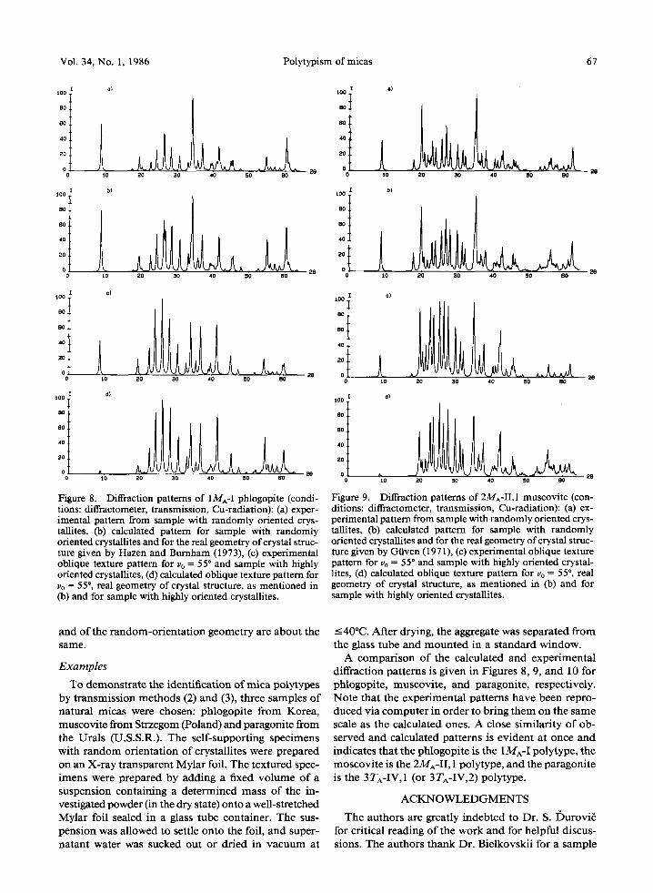
Figure 8. Diffraction patterns of 1MA-I phlogopite (condi- tions: diffractometer, transmission, Cu-radiation): (a) exper- imental pattern from sample with randomly oriented crys- tallites, (b) calculated pattern for sample with randomly oriented crystallites and for the real geometry of crystal struc- ture given by Hazen and Burnham (1973), (c) experimental oblique texture pattern for Uo = 55* and sample with highly oriented crystallites, (d) calculated oblique texture pattern for Vo = 55*, real geometry of crystal structure, as mentioned in (b) and for sample with highly oriented crystallites.
a) IO0
BO
80
40
o t o
b} 1 0 0 ,
B O
8 0 , .! 10 .
2 0 .
0 10
20 30 40 50 BO
20 30 40 50 BO
c) $ o o
8O
4O
2o
10 20 20 40 50 B0
a} t00
8O
4 0
20
0 �9 28 i0 20 30 40 50 OO
Figure 9. Diffraction patterns of 2MA-II, 1 muscovite (con- ditions: diffractometer, transmission, Cu-radiation): (a) ex- perimental pattern from sample with randomly oriented crys- tallites, (b) calculated pattern for sample with randomly oriented crystallites and for the real geometry of crystal struc- ture given by Graven (1971), (c) experimental oblique texture pattern for ~'o = 55 ~ and sample with highly oriented crystal- lites, (d) calculated oblique texture pattern for ~'o = 55~ real geometry of crystal structure, as mentioned in (b) and for sample with highly oriented crystallites.
and of the random-orientation geometry are about the same.
Examples
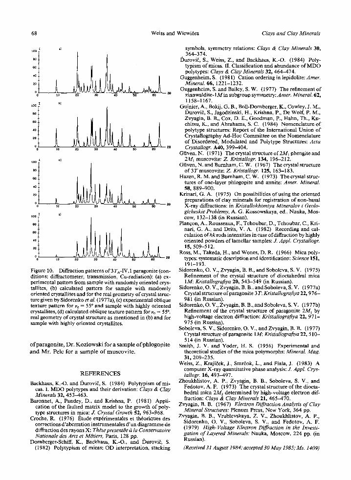
To demonstrate the identification of mica polytypes by transmission methods (2) and (3), three samples of natural micas were chosen: phlogopite from Korea, muscovite from Strzegom (Poland) and paragonite from the Urals (U.S.S.R.). The self-supporting specimens with random orientation of crystallites were prepared on an X-ray transparent Mylar foil. The textured spec- imens were prepared by adding a fixed volume of a suspension containing a determined mass of the in- vestigated powder (in the dry state) onto a well-stretched Mylar foil sealed in a glass tube container. The sus- pension was allowed to settle onto the foil, and super- natant water was sucked out or dried in vacuum at
-<40~ After drying, the aggregate was separated from the glass tube and mounted in a standard window.
A comparison of the calculated and experimental diffraction patterns is given in Figures 8, 9, and 10 for phlogopite, muscovite, and paragonite, respectively. Note that the experimental patterns have been repro- duced via computer in order to bring them on the same scale as the calculated ones. A close similarity of ob- served and calculated patterns is evident at once and indicates that the phlogopite is the IMA-I polytype, the moscovite is the 2MA-II, I polytype, and the paragonite is the 3 TA-IV, I (or 3 TA-IV,2) polytype.
ACKNOWLEDGMENTS
The authors are greatly indebted to Dr. S. I)urovi~ for critical reading of the work and for helpful discus- sions. The authors thank Dr. Bielkovskii for a sample
68 Weiss and Wiewi6ra Clays and Clay Minerals
100
80
80
40
20
0
t00
80
80
40
20
0
10 ~0 30 40 50 80
tO 28
20 30 40 50 80
100 ,
80
80
40
20
0
100
80
80
40
20
0
10 20 30 40 50 80
OI
28
t0 20 30 40 50 80
Figure 10. Diffraction patterns of 3 TA-IV, 1 paragonite (con- ditions: diffractometer, transmission, Cu-radiation): (a) ex- perimental pattern from sample with randomly oriented crys- tallites, (b) calculated pattern for sample with randomly oriented crystallites and for the real geometry of crystal struc- ture given by Sidorenko et al. (1977a), (c) experimental oblique texture pattern for v0 = 55 ~ and sample with highly oriented crystallites, (d) calculated oblique texture pattern for Vo -~ 55 ~ real geometry of crystal structure as mentioned in (b) and for sample with highly oriented crystallites.
ofparagonite, Dr. Kozlowski for a sample ofphlogopite and Mr. Pelc for a sample of muscovite.
REFERENCES
Backhaus, K.-O. and I)urovi~, S. (1984) Polytypism of mi- cas. I. MDO polytypes and their derivation: Clays & Clay Minerals 32, 453-463.
Baronnet, A., Pandey, D., and K_rishna, P. (1981) Appli- cation of the faulted matrix model to the growth of poly- type structures in mica: J. Crystal Growth 52, 963-968.
Croche, R. (1976) IStude exprrimentales et throriques des corrections d'aberration instrumentales d'un diagramme de diffraction des rayons X: Thdse present~e s la Conservatoire Nationale des Arts et M~tiers, Paris, 128 pp.
Dornberger-Schiff, K., Backhaus, K.-O., and I)urovi~, S. (1982) Polytypism of micas: OD interpretation, stacking
symbols, symmetry relations: Clays & Clay Minerals 30, 364-374.
I)urovi~, S., Weiss, Z., and Backhaus, K.-O. (1984) Poly- typism of micas. II. Classification and abundance of MDO polytypes: Clays & Clay Minerals 32, 464-474.
Guggenheim, S. (1981) Cation ordering in lepidolite: Amer. Mineral. 66, 1221-1232.
Guggenheim, S. and Bailey, S.W. (1977) The refinement of zinnwaldite-1Min subgroup symmetry: Amer. Mineral. 62, 1158-1167.
Guinier, A., Bokij, G. B., Boll-Dornberger, K., Cowley, J. M., Durovir, S., Jagodzinski, H., Krishna, P., De Wolf, P. M., Zvyagin, B. B., Cox, D. E., Goodman, P., Hahn, Th., Ku- chitsu, K., and Abrahams, S. C. (1984) Nomenclature of polytype structures: Report of the International Union of Crystallography Ad-Hoc Committee on the Nomenclature of Disordered, Modulated and Polytype Structures: Acta Crystallogr. A40, 399-404.
Gtiven, N. (1971) The crystal structure of2M1 phengite and 2M1 muscovite: Z. Kristallogr. 134, 196-212.
Graven, N. and Burnham, C.W. (1967) The crystal structure of3T muscovite: Z. Kristallogr. 125, 163-183.
Hazen, R. M. and Burnham, C. W. (1973) The crystal struc- tures of one-layer phlogopite and annite: Amer. Mineral. 58, 889-900.
Krinari, G.A. (1975) On possibilities of using the oriented preparations of clay minerals for registration of non-basal X-ray diffractions: in Kristallokhimiya Mineralov i Geolo- gicheskie Problemy, A. G. Kossowskaya, ed., Nauka, Mos- cow, 132-138 (in Russian).
Plan~on, A., Rousseaux, F., Tchoubar, D., Tchoubar, C., Kri- nail, G. A., and Drits, V. A. (1982) Recording and cal- culation ofhk rods intensities in case of diffraction by highly oriented powders oflamellar samples: J. Appl. Crystallogr. 15, 509-512.
Ross, M., Takeda, H., and Wones, D. R. (1966) Mica poly- types: systematic description and identification: Science 151, 191-193.
Sidorenko, O. V., Zvyagin, B. B., and Soboleva, S.V. (1975) Refinement of the crystal structure of dioctahedral mica 1M: Kristallografiya 20, 543-549 (in Russian).
Sidorenko, O. V., Zvyagin, B. B., and Soboleva, S.V. (1977a) Crystal structure ofparagonite 3T: Kristallografiya 22, 976- 981 (in Russian).
Sidorenko, O. V., Zvyagin, B. B., and Soboleva, S.V. (1977b) Refinement of the crystal structure of paragonite 2M~ by high-voltage electron diffraction: Kristallografiya 22, 971- 975 (in Russian).
Soboleva, S. V., Sidorenko, O. V., and Zvyagin, B. B, (1977) Crystal structure of paragonite 134: Kristallografiya 22, 510-- 514 (in Russian).
Smith, J. V. and Yoder, H. S. (1956) Experimental and theoretical studies of the mica polymorphs: Mineral. Mag. 31, 209-235.
Weiss, Z., Krajirek, J., Smrrok, L., and Fiala, J. (1983) A computer X-ray quantitative phase analysis: J. Appl. Crys- tallogr. 16, 493-497.
Zhoukhlistov, A. P., Zvyagin, B. B., Soboleva, S. V., and Fedotov, A. F. (1973) The crystal structure of the diocta- bedral mica 2M2 determined by high-voltage electron dif- fraction: Clays & Clay Minerals 21, 465-470.
Zvyagin, B. B. (1967) Electron Diffraction Analysis of Clay Mineral Structures: Plenum Press, New York, 364 pp.
Zvyagin, B. B., Vrublevskaya, Z. V., Zhoukhlistov, A. P., Sidorenko, O. V., Soboleva, S. V., and Fedotov, A. F. (1979) High-Voltage Electron Diffraction in the Investi- gation of Layered Minerals: Nauka, Moscow, 224 pp. (in Russian).
(Received 31 August 1984; accepted 30 May 1985; Ms. 1409)