Embed Size (px)
Citation preview
Power Electronics Lecture No.9 Dr.Mohammed Tawfeeq
1
9. DC-DC Converters (DC –Choppers) A dc‐to‐dc converter, also known as dc chopper, is a static device which
is used to obtain a variable dc voltage from a constant dc voltage source. Choppers are widely used in trolley cars, battery operated vehicles, traction motor control, control of large number of dc motors, etc….. They are also used as dc voltage regulators. Choppers are of two types: (1) Step‐down choppers, and (2) Step‐up
choppers. In step‐down choppers, the output voltage will be less than
the input voltage, whereas in step‐up choppers output voltage will be
more than the input voltage.
9.1 PRINCIPLE OF STEP‐DOWN CHOPPER
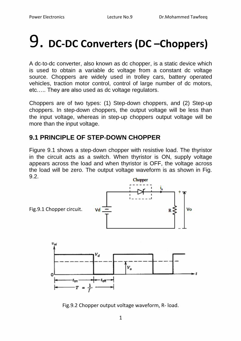
Figure 9.1 shows a step‐down chopper with resistive load. The thyristor
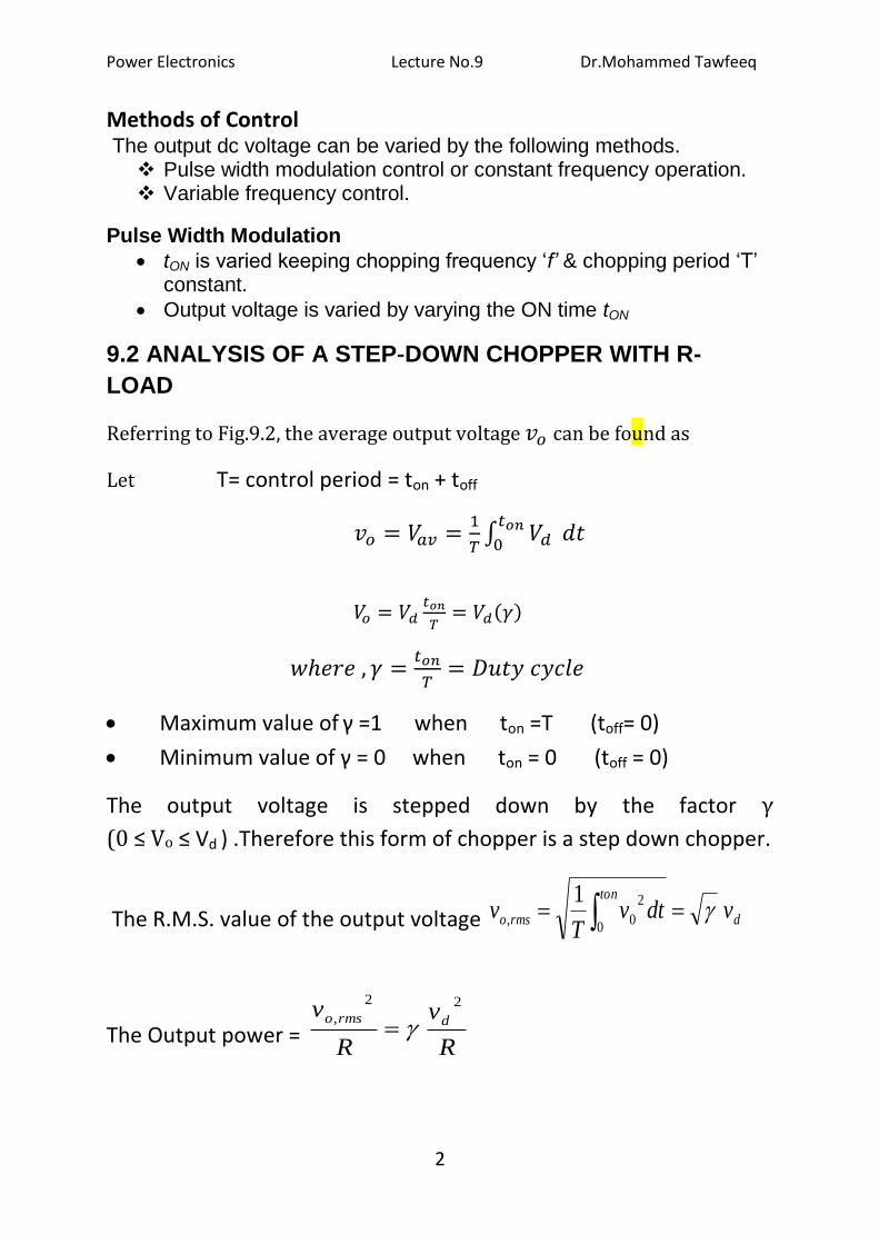
in the circuit acts as a switch. When thyristor is ON, supply voltage appears across the load and when thyristor is OFF, the voltage across the load will be zero. The output voltage waveform is as shown in Fig. 9.2.
Fig.9.1 Chopper circuit.
Fig.9.2 Chopper output voltage waveform, R- load.
Power Electronics Lecture No.9 Dr.Mohammed Tawfeeq
2
Methods of Control The output dc voltage can be varied by the following methods. Pulse width modulation control or constant frequency operation. Variable frequency control.
Pulse Width Modulation
tON is varied keeping chopping frequency ‘f’ & chopping period ‘T’ constant.
Output voltage is varied by varying the ON time tON
9.2 ANALYSIS OF A STEP‐DOWN CHOPPER WITH R-
LOAD
Referring to Fig.9.2, the average output voltage can be found as
Let T= control period = ton + toff
Maximum value of γ =1 when ton =T (toff= 0)
Minimum value of γ = 0 when ton = 0 (toff = 0)
The output voltage is stepped down by the factor γ
(0 ≤ Vo ≤ Vd ) .Therefore this form of chopper is a step down chopper.
The R.M.S. value of the output voltage d
ton
rmso vdtvT
v 02
0,
1
The Output power = R
v
R
vdrmso
22
,
Power Electronics Lecture No.9 Dr.Mohammed Tawfeeq
3
Input current (Assume 100% efficiency) R
v
vR
v
V
PI d
d
da
12
f= chopping frequency = ))(
1(
Tperiodchopping= 1/ T
The ripple factor, RF
It is a measure of the ripple content.
11
11)(1)(
22
2
2
d
drms
V
V
Vo
VoRF
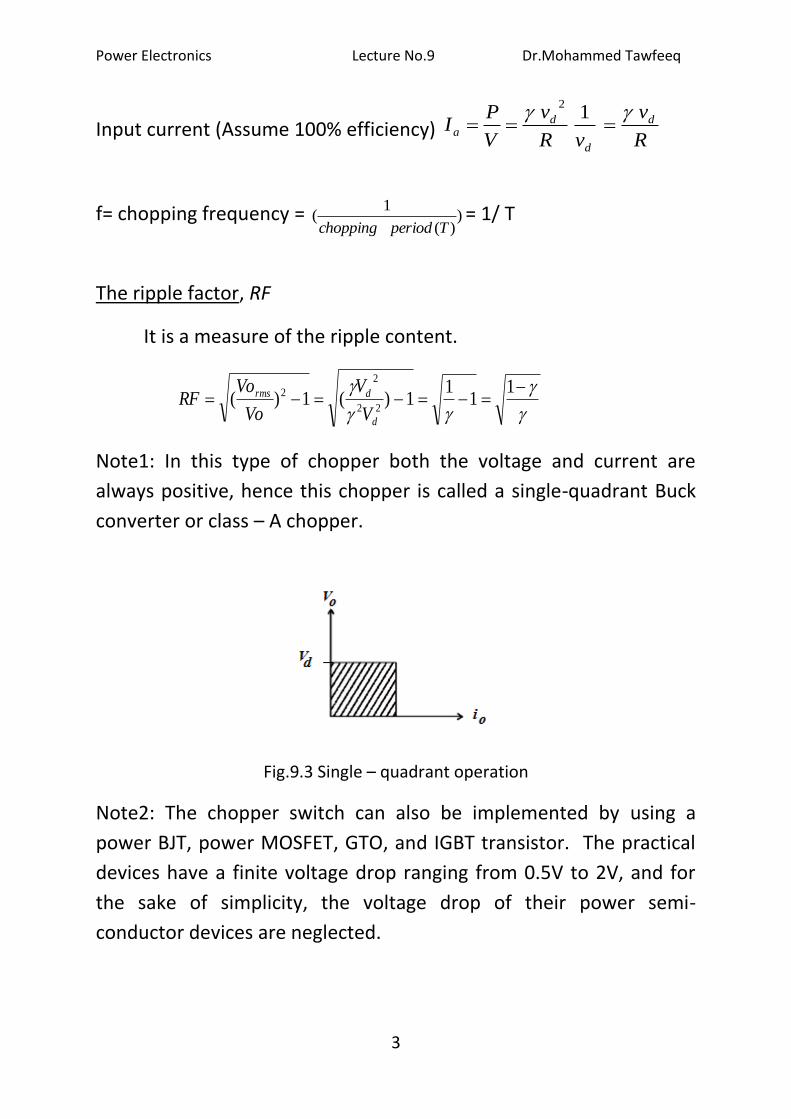
Note1: In this type of chopper both the voltage and current are
always positive, hence this chopper is called a single-quadrant Buck
converter or class – A chopper.
Fig.9.3 Single – quadrant operation
Note2: The chopper switch can also be implemented by using a
power BJT, power MOSFET, GTO, and IGBT transistor. The practical
devices have a finite voltage drop ranging from 0.5V to 2V, and for
the sake of simplicity, the voltage drop of their power semi-
conductor devices are neglected.
Power Electronics Lecture No.9 Dr.Mohammed Tawfeeq
4
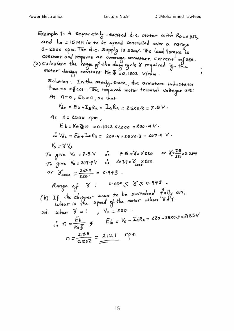
Example 1: A transistor dc chopper circuit (Buck converter) is supplied with power form an ideal battery of 100 V. The load voltage waveform consists of rectangular pulses of duration 1 ms in an overall cycle time of 2.5 ms. Calculate, for resistive load of 10 Ω.
(a) The duty cycle γ.
(b) The average value of the output voltage Vo.
(c) The rms value of the output voltage Vorms.
(d) The ripple factor RF.
(e) The output dc power.
Solution:
(a) ton = 1ms , T=2.5 ms
(b) Vav =Vo = γ Vd = 0.4 x 100 = 40 V.
(c ) = √0.4 x100 = 63.2 V.
(d) 225.14.0
4.011
RF
(e)
Pav = Ia Vo = 4x40 = 160 W
Power Electronics Lecture No.9 Dr.Mohammed Tawfeeq
5
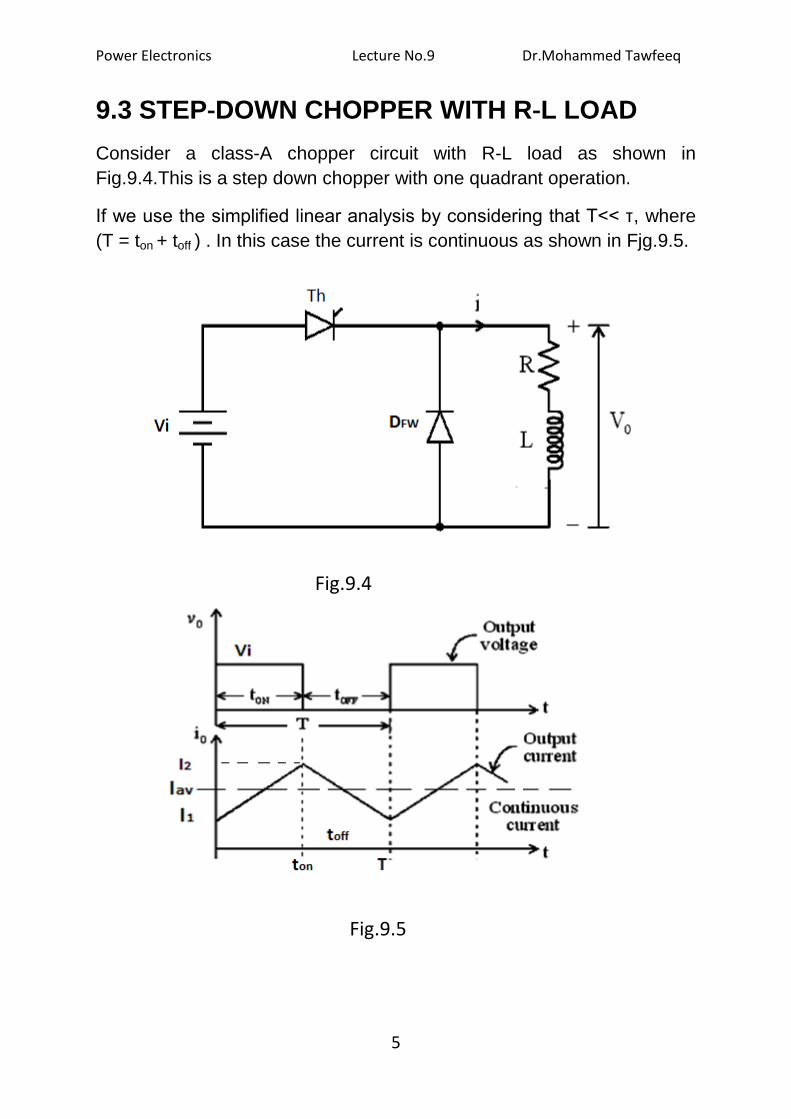
9.3 STEP‐DOWN CHOPPER WITH R‐L LOAD
Consider a class-A chopper circuit with R-L load as shown in
Fig.9.4.This is a step down chopper with one quadrant operation.
If we use the simplified linear analysis by considering that T<< τ, where
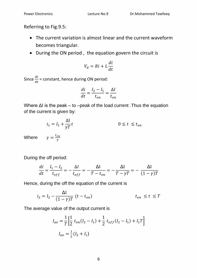
(T = ton + toff ) . In this case the current is continuous as shown in Fjg.9.5.
Fig.9.4
Fig.9.5
Power Electronics Lecture No.9 Dr.Mohammed Tawfeeq
6
Referring to Fig.9.5:
The current variation is almost linear and the current waveform
becomes triangular.
During the ON period , the equation govern the circuit is
Since
= constant, hence during ON period:
Where ΔI is the peak – to –peak of the load current .Thus the equation
of the current is given by:
Where
During the off period:
Δ
Δ
Δ
Hence, during the off the equation of the current is
Δ
The average value of the output current is
)
Power Electronics Lecture No.9 Dr.Mohammed Tawfeeq
7
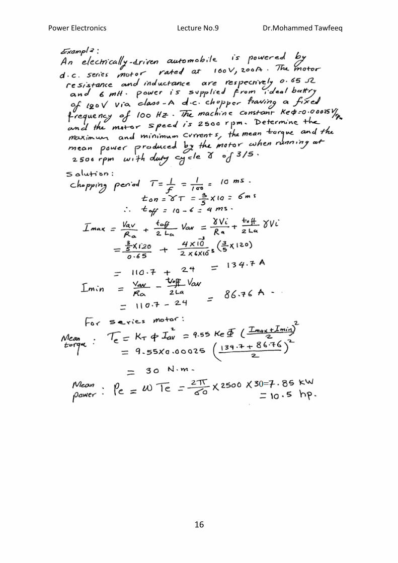
Example 2; An 80 V battery supplies RL load through a DC chopper.
The load has a freewheeling diode across it is composed of 0.4 H in
series with 5Ω resistor. Load current, due to improper selection of
frequency of chopping, varies widely between 9A and 10.2.
(a) Find the average load voltage, current and the duty cycle of the
chopper.
(b) What is the operating frequency f ?
(c) Find the ripple current to maximum current ratio.
Solution:
(a) The average load voltage and current are:
Vav = Vo = γ Vd
Vav = 0.6 x 80 = 48 V.
(b) To find the operating (chopping) frequency:
During the ON period,
Assuming
From eq.(1)
or
Power Electronics Lecture No.9 Dr.Mohammed Tawfeeq
8
but
Hence
The maximum current Im occurs at γ = 1,
Ripple current Ir = ΔI = 10.2- 9 =1.2 A
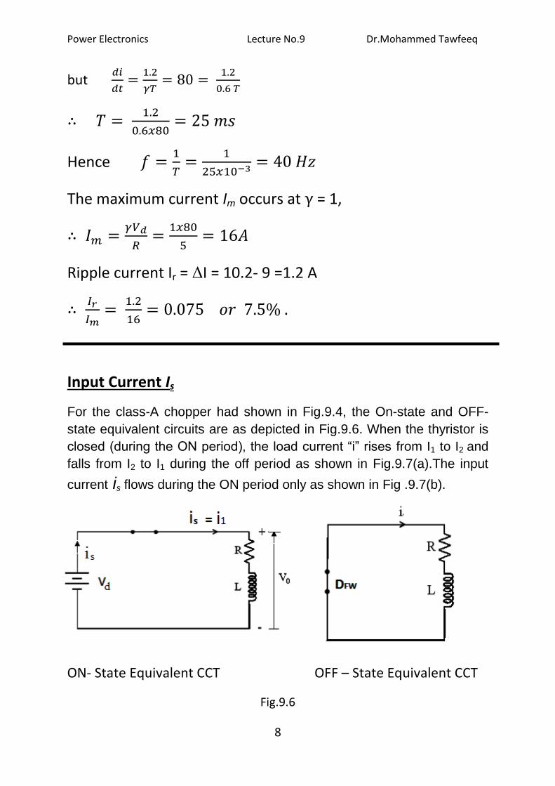
Input Current Is
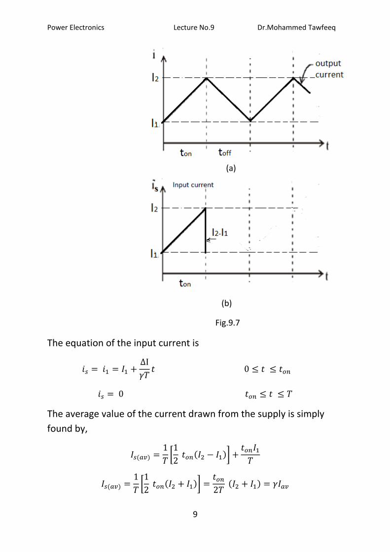
For the class-A chopper had shown in Fig.9.4, the On-state and OFF-
state equivalent circuits are as depicted in Fig.9.6. When the thyristor is
closed (during the ON period), the load current “i” rises from I1 to I2 and
falls from I2 to I1 during the off period as shown in Fig.9.7(a).The input
current is flows during the ON period only as shown in Fig .9.7(b).
ON- State Equivalent CCT OFF – State Equivalent CCT
Fig.9.6
Power Electronics Lecture No.9 Dr.Mohammed Tawfeeq
9
(a)
(b)
Fig.9.7
The equation of the input current is
The average value of the current drawn from the supply is simply
found by,
Power Electronics Lecture No.9 Dr.Mohammed Tawfeeq
10
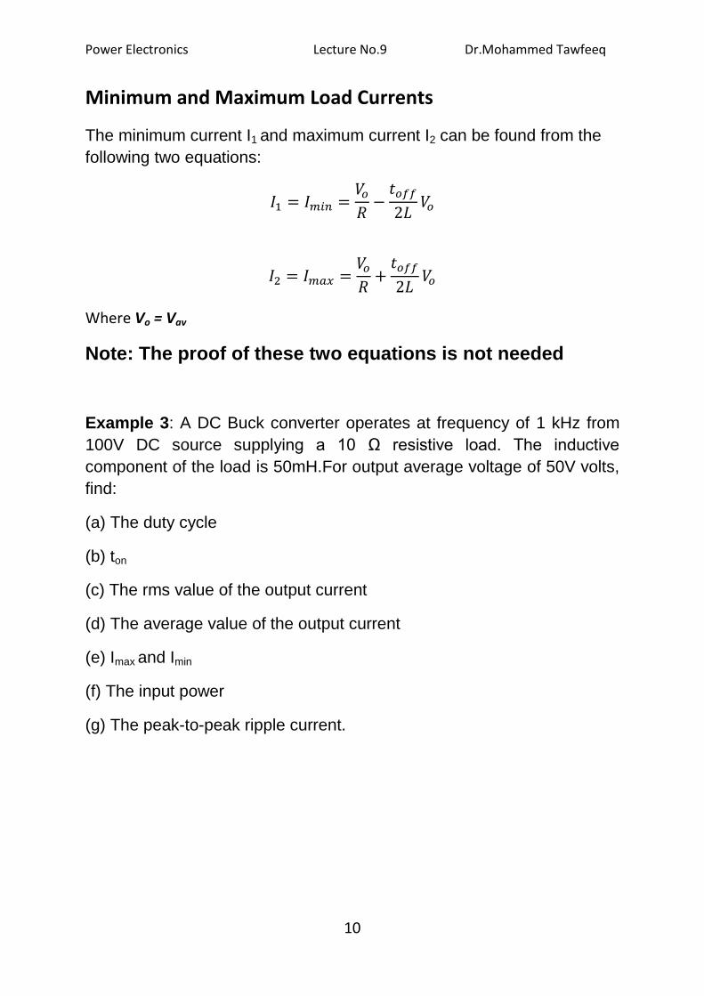
Minimum and Maximum Load Currents
The minimum current I1 and maximum current I2 can be found from the
following two equations:
Where Vo = Vav
Note: The proof of these two equations is not needed
Example 3: A DC Buck converter operates at frequency of 1 kHz from
100V DC source supplying a 10 Ω resistive load. The inductive
component of the load is 50mH.For output average voltage of 50V volts,
find:
(a) The duty cycle
(b) ton
(c) The rms value of the output current
(d) The average value of the output current
(e) Imax and Imin
(f) The input power
(g) The peak-to-peak ripple current.
Power Electronics Lecture No.9 Dr.Mohammed Tawfeeq
11
Solution:
(a) Vav =Vo = γ Vd
(b) T= 1/ f = 1 / 1000 = 1ms
ton = γ T = 05 x1ms= 0.5 ms .
(c ) =
(d)
(e)
= 5 + 0.25 = 5,25 A
= 5 - 0.25 = 4.75 A
(f)
(g)
Power Electronics Lecture No.9 Dr.Mohammed Tawfeeq
12
9.4 Application to DC Drives
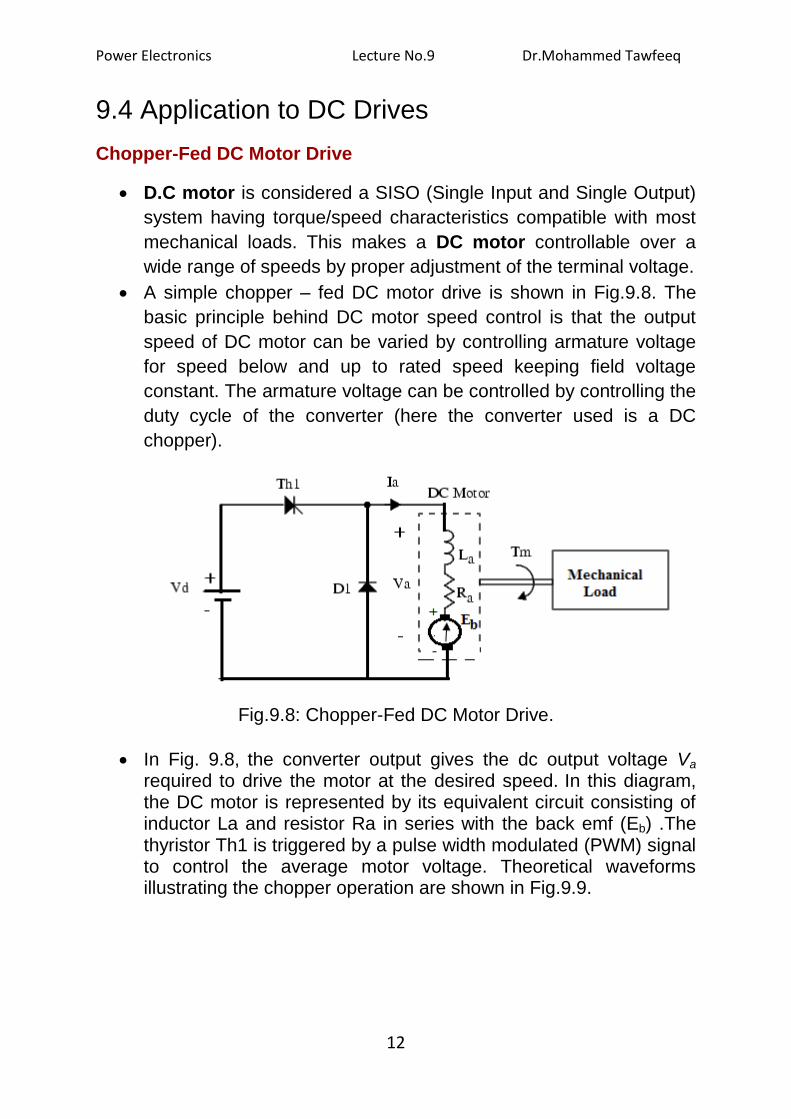
Chopper-Fed DC Motor Drive
D.C motor is considered a SISO (Single Input and Single Output)
system having torque/speed characteristics compatible with most
mechanical loads. This makes a DC motor controllable over a
wide range of speeds by proper adjustment of the terminal voltage.
A simple chopper – fed DC motor drive is shown in Fig.9.8. The
basic principle behind DC motor speed control is that the output
speed of DC motor can be varied by controlling armature voltage
for speed below and up to rated speed keeping field voltage
constant. The armature voltage can be controlled by controlling the
duty cycle of the converter (here the converter used is a DC
chopper).
Fig.9.8: Chopper-Fed DC Motor Drive.
In Fig. 9.8, the converter output gives the dc output voltage Va required to drive the motor at the desired speed. In this diagram, the DC motor is represented by its equivalent circuit consisting of inductor La and resistor Ra in series with the back emf (Eb) .The thyristor Th1 is triggered by a pulse width modulated (PWM) signal to control the average motor voltage. Theoretical waveforms illustrating the chopper operation are shown in Fig.9.9.

Power Electronics Lecture No.9 Dr.Mohammed Tawfeeq
13
Fig.9.9
The average armature voltage is a direct function of the chopper duty
cycle γ ,
Vav = γ Vd
Note that this relation is valid only when the armature current is continuous. In steady state, the armature average current is equal to
Where Iav = average armature current (A).
Eb is the internal generated voltage (back emf) is given by:
Eb = Ke φ n
Finally, solving for the motor’s speed:
Power Electronics Lecture No.9 Dr.Mohammed Tawfeeq
14
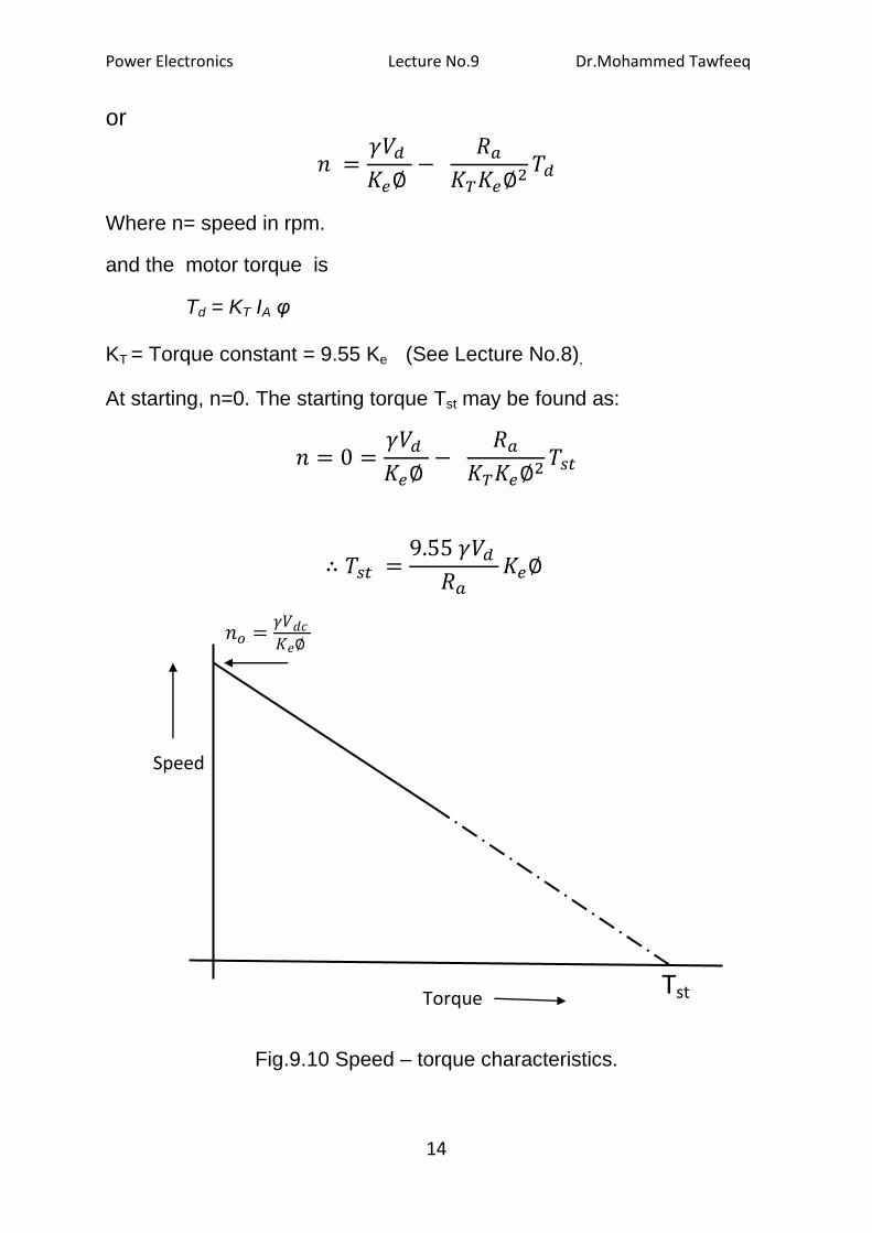
or
Where n= speed in rpm.
and the motor torque is
Td = KT IA φ
KT = Torque constant = 9.55 Ke (See Lecture No.8),
At starting, n=0. The starting torque Tst may be found as:
Fig.9.10 Speed – torque characteristics.
Speed
Torque Tst
Power Electronics Lecture No.9 Dr.Mohammed Tawfeeq
15
Power Electronics Lecture No.9 Dr.Mohammed Tawfeeq
16