Embed Size (px)
DESCRIPTION
POWER SYSTEM GROUNDING. Presented By H.JAYAKUMAR. WHY GROUNDING IS REQUIRED?. - PowerPoint PPT Presentation
Citation preview

POWER SYSTEM GROUNDING
Presented
By
H.JAYAKUMAR
WHY GROUNDING IS REQUIRED?WHY GROUNDING IS REQUIRED?
GROUNDINGGROUNDING PLAYS A VITAL ROLE IN POWER PLAYS A VITAL ROLE IN POWER SYSTEM OPERATION. EFFECTIVE GROUNDING SYSTEM OPERATION. EFFECTIVE GROUNDING IS NECESSARY FOR THE PROPER OPERATION IS NECESSARY FOR THE PROPER OPERATION AND CO-ORDINATION OF PROTECTION AND CO-ORDINATION OF PROTECTION SCHEMES IN THE POWER SYSTEM AS WELL SCHEMES IN THE POWER SYSTEM AS WELL AS FOR PERSONNEL SAFETY.AS FOR PERSONNEL SAFETY.
PURPOSE OF EARTHING:PURPOSE OF EARTHING:
• PROTECTION OF INSTALLATION.
• IMPROVEMENT IN QUALITY OF SERVICE.
• SAFTY OF PERSONNEL.
GENERAL REQUIREMENTS:GENERAL REQUIREMENTS:
• LOW VALUE OF EARTH RESISTANCE.
• ACCEPTABLE SURFACE POTENTIAL GRADIENTS.
RULES/GUIDELINES:RULES/GUIDELINES:
• INDIAN ELECTRICITY RULES 1956.
• IS: 3043/1966, 1987 : CODE OF PRACTICE
FOR EARTHING.
• BS : CP 1013:1965
• CBI & P RECOMMENDATIONS
• CIGRE APPLICATION GUIDE
• ANSI / IEEE STD.80/ 1961,1967,1986.
TYPES OF EARTHING:TYPES OF EARTHING:
• SYSTEM EARTHING.
• PROTECTIVE EARTHING.
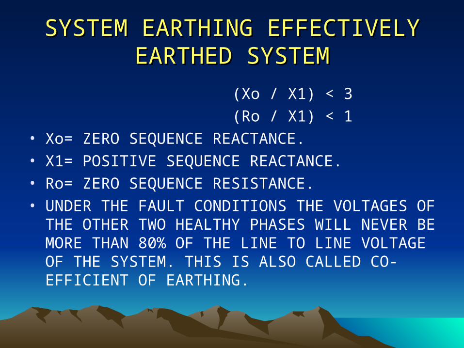
SYSTEM EARTHING EFFECTIVELY SYSTEM EARTHING EFFECTIVELY EARTHED SYSTEMEARTHED SYSTEM
(Xo / X1) < 3
(Ro / X1) < 1• Xo= ZERO SEQUENCE REACTANCE.• X1= POSITIVE SEQUENCE REACTANCE.• Ro= ZERO SEQUENCE RESISTANCE.• UNDER THE FAULT CONDITIONS THE VOLTAGES
OF THE OTHER TWO HEALTHY PHASES WILL NEVER BE MORE THAN 80% OF THE LINE TO LINE VOLTAGE OF THE SYSTEM. THIS IS ALSO CALLED CO-EFFICIENT OF EARTHING.
OBJECTIVE OF SOIL RESISTIVITY OBJECTIVE OF SOIL RESISTIVITY MEASUREMENTS:MEASUREMENTS:
• Estimating the ground resistance of a proposed sub-station or transmission tower.
• Estimating potential gradients including step and touch voltages.
• Computing the inductive coupling between neighbouring power and communication circuits.
• Designing cathodic protection systems.• Geographical surveying.
FACTORS AFFECTING THE FACTORS AFFECTING THE SOIL RESISTIVITY:SOIL RESISTIVITY:
• Type of the soil.
• Moisture.
• Dissolved salt in water.
• Temperature.
• Grain size and its distribution.
• Seasonal variation.
• Artificial treatment.
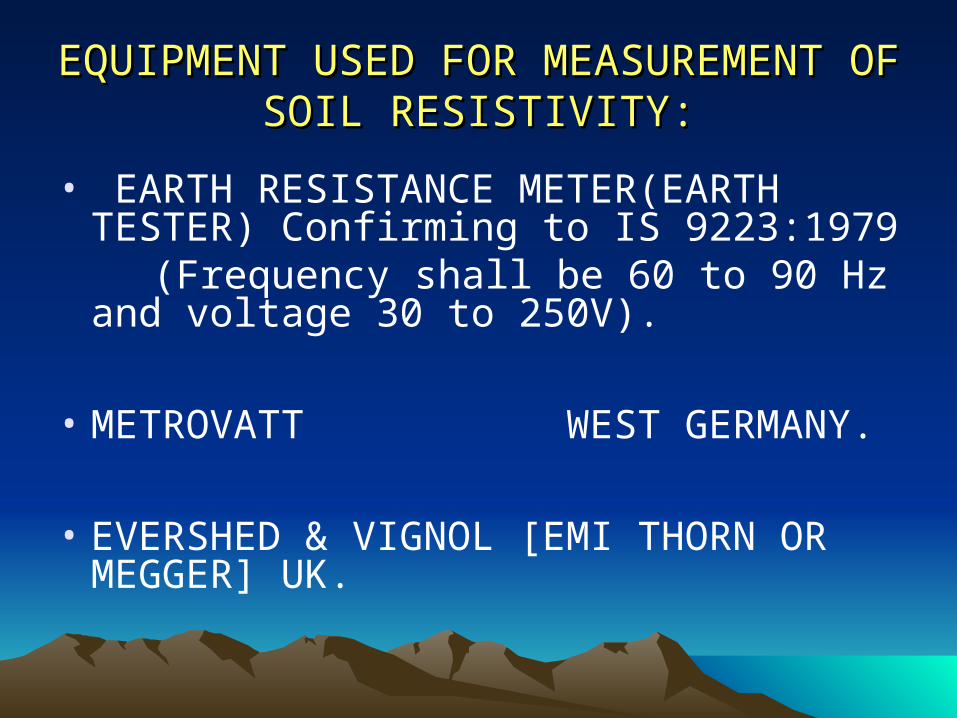
EQUIPMENT USED FOR MEASUREMENT EQUIPMENT USED FOR MEASUREMENT OF SOIL RESISTIVITY:OF SOIL RESISTIVITY:
• EARTH RESISTANCE METER(EARTH TESTER) Confirming to IS 9223:1979
(Frequency shall be 60 to 90 Hz and voltage 30 to 250V).
• METROVATT WEST GERMANY.
• EVERSHED & VIGNOL [EMI THORN OR MEGGER] UK.
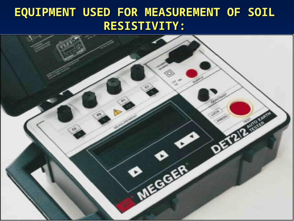
EQUIPMENT USED FOR MEASUREMENT OF EQUIPMENT USED FOR MEASUREMENT OF SOIL RESISTIVITY:SOIL RESISTIVITY:
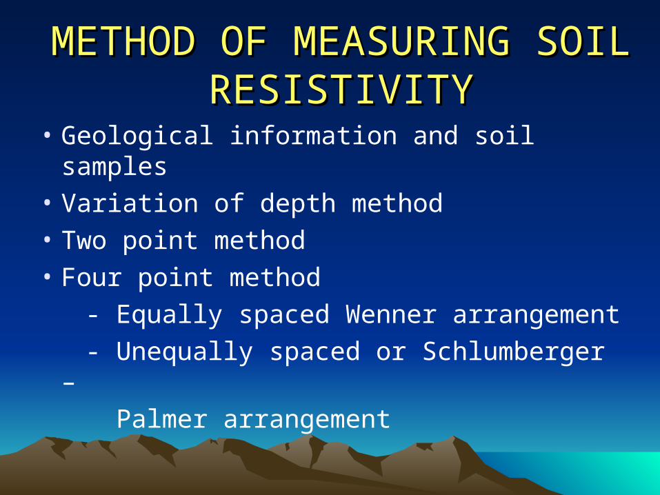
METHOD OF MEASURING SOIL METHOD OF MEASURING SOIL RESISTIVITYRESISTIVITY
• Geological information and soil samples
• Variation of depth method
• Two point method
• Four point method
- Equally spaced Wenner arrangement
- Unequally spaced or Schlumberger –
Palmer arrangement
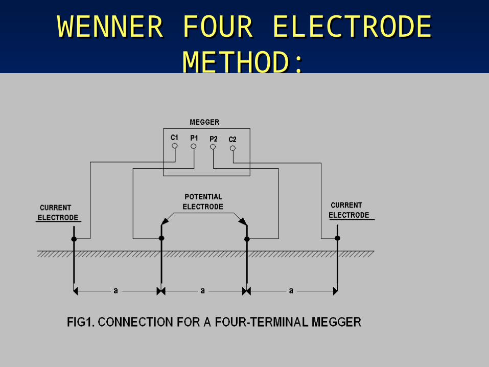
WENNER FOUR ELECTRODE WENNER FOUR ELECTRODE METHOD:METHOD:
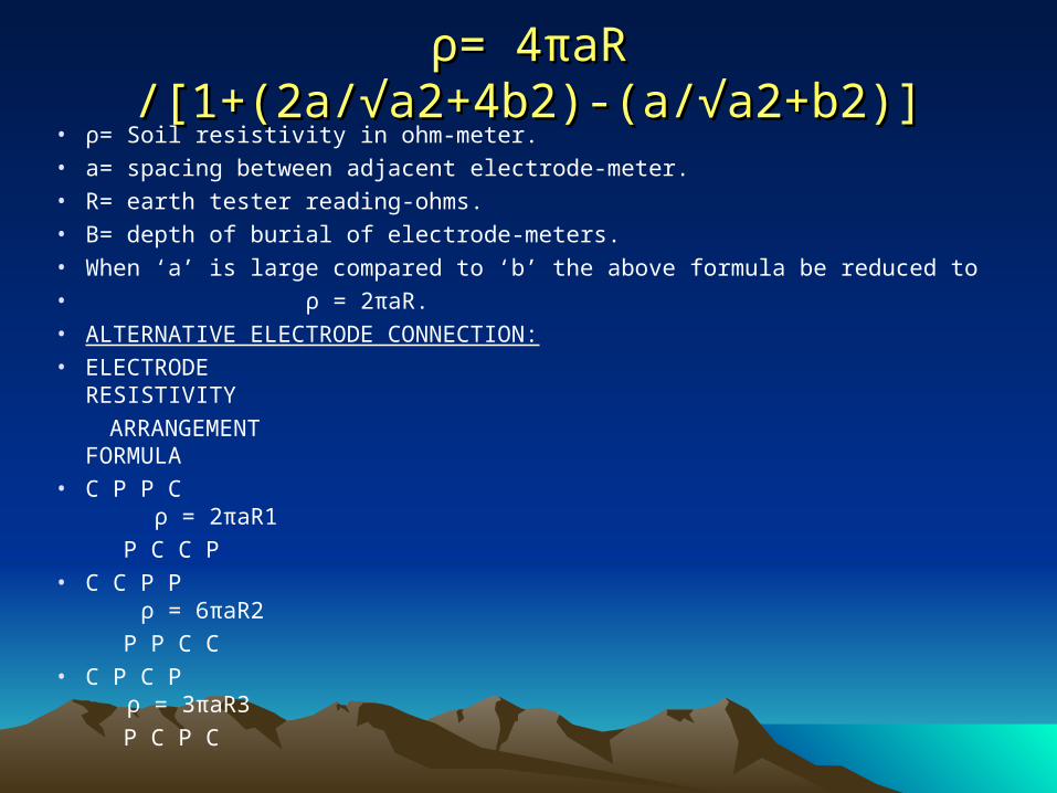
ρρ= 4= 4ππaR /[1+(2a/√a2+4b2)-(a/√a2+b2)]aR /[1+(2a/√a2+4b2)-(a/√a2+b2)]• ρ= Soil resistivity in ohm-meter.• a= spacing between adjacent electrode-meter.• R= earth tester reading-ohms.• B= depth of burial of electrode-meters.• When ‘a’ is large compared to ‘b’ the above formula be reduced to • ρ = 2πaR.• ALTERNATIVE ELECTRODE CONNECTION:• ELECTRODE RESISTIVITY
ARRANGEMENT FORMULA• C P P C ρ = 2πaR1
P C C P• C C P P ρ = 6πaR2
P P C C• C P C P ρ = 3πaR3
P C P C
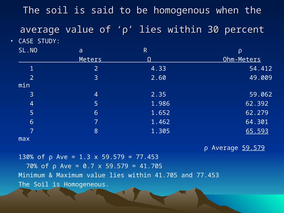
The soil is said to be homogenous when the average value The soil is said to be homogenous when the average value
of ‘of ‘ρρ’ lies within 30 percent’ lies within 30 percent • CASE STUDY:
SL.NO a R ρ
Meters Ω Ohm-Meters
1 2 4.33 54.412
2 3 2.60 49.009 min
3 4 2.35 59.062
4 5 1.986 62.392
5 6 1.652 62.279
6 7 1.462 64.301
7 8 1.305 65.593 max
ρ Average 59.579
130% of ρ Ave = 1.3 x 59.579 = 77.453
70% of ρ Ave = 0.7 x 59.579 = 41.705
Minimum & Maximum value lies within 41.705 and 77.453
The Soil is Homogeneous.
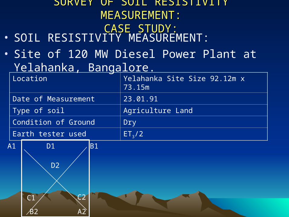
SURVEY OF SOIL RESISTIVITY MEASUREMENT:SURVEY OF SOIL RESISTIVITY MEASUREMENT:CASE STUDY:CASE STUDY:
• SOIL RESISTIVITY MEASUREMENT:• Site of 120 MW Diesel Power Plant at Yelahanka,
Bangalore.Location Yelahanka Site Size 92.12m x 73.15m
Date of Measurement 23.01.91
Type of soil Agriculture Land
Condition of Ground Dry
Earth tester used ET3/2
A1 D1 B1
D2
C1 C2
B2 A2
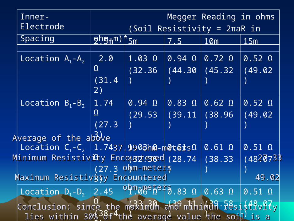
Average of the above 37.99 ohm-metersAverage of the above 37.99 ohm-metersMinimum Resistivity Encountered 27.33 ohm-metersMinimum Resistivity Encountered 27.33 ohm-metersMaximum Resistivity Encountered 49.02 ohm-metersMaximum Resistivity Encountered 49.02 ohm-meters
Conclusion: since the maximum and minimum resistivity lies within 30% of Conclusion: since the maximum and minimum resistivity lies within 30% of the average value the soil is a homogeneous one the average value the soil is a homogeneous one
Inner- Electrode
Spacing
Megger Reading in ohms
(Soil Resistivity = 2πaR in ohm-m)*
2.5m 5m 7.5 10m 15m
Location A1-A2 2.0 Ω
(31.42)
1.03 Ω
(32.36)
0.94 Ω
(44.30)
0.72 Ω
(45.32)
0.52 Ω
(49.02)
Location B1-B2 1.74 Ω
(27.33)
0.94 Ω
(29.53)
0.83 Ω
(39.11)
0.62 Ω
(38.96)
0.52 Ω
(49.02)
Location C1-C2 1.74 Ω
(27.33)
1.03 Ω
(32.36)
0.61 Ω
(28.74)
0.61 Ω
(38.33)
0.51 Ω
(48.07)
Location D1-D2 2.45 Ω
(38.48)
1.06 Ω
(33.30)
0.83 Ω
(39.11)
0.63 Ω
(39.58)
0.51 Ω
(48.07)
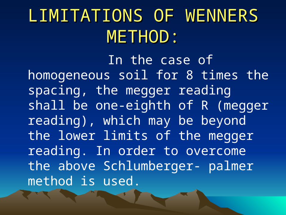
LIMITATIONS OF WENNERS LIMITATIONS OF WENNERS METHOD:METHOD:
In the case of homogeneous soil for 8 times the spacing, the megger reading shall be one-eighth of R (megger reading), which may be beyond the lower limits of the megger reading. In order to overcome the above Schlumberger- palmer method is used.
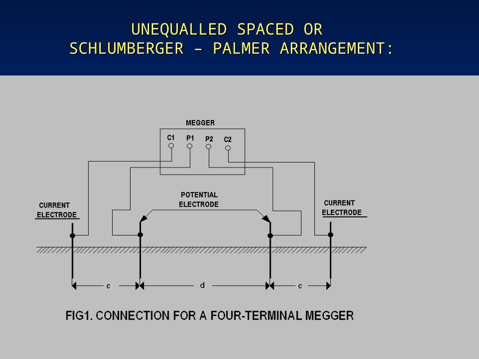
UNEQUALLED SPACED OR UNEQUALLED SPACED OR SCHLUMBERGER – PALMER ARRANGEMENT:SCHLUMBERGER – PALMER ARRANGEMENT:
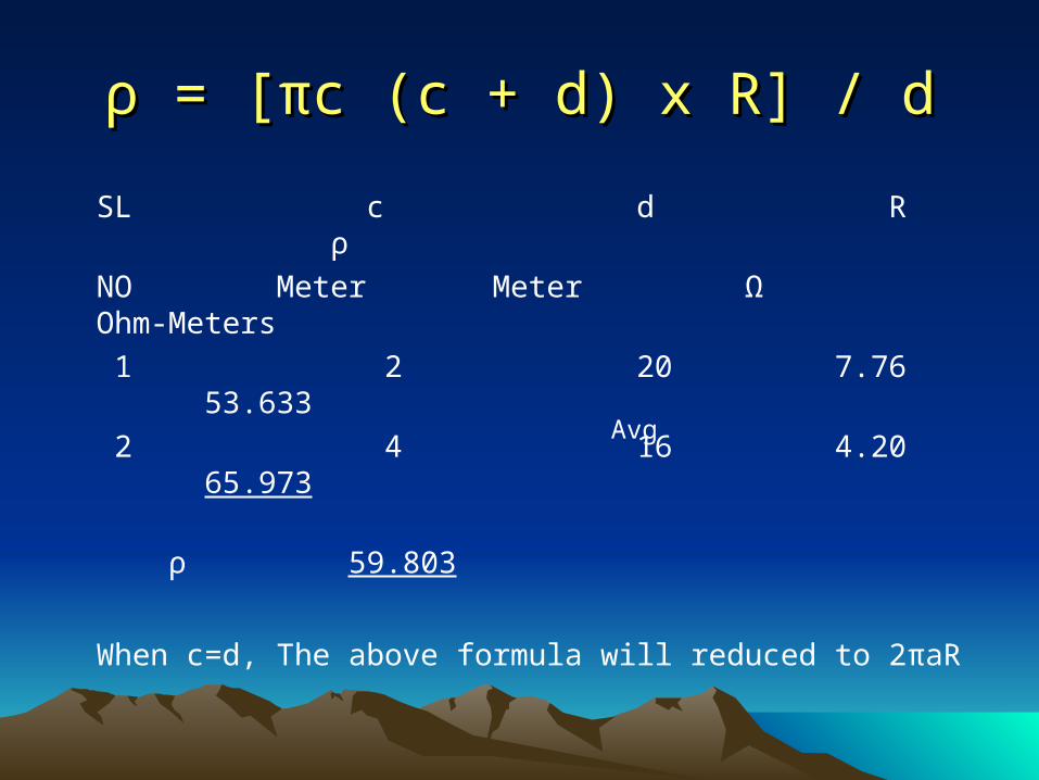
ρρ = [ = [ππc (c + d) x R] / dc (c + d) x R] / d
SL c d R ρ
NO Meter Meter Ω Ohm-Meters
1 2 20 7.76 53.633
2 4 16 4.20 65.973
ρ 59.803
When c=d, The above formula will reduced to 2πaR
Avg
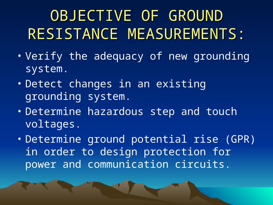
OBJECTIVE OF GROUND OBJECTIVE OF GROUND RESISTANCE MEASUREMENTS:RESISTANCE MEASUREMENTS:
• Verify the adequacy of new grounding system.
• Detect changes in an existing grounding system.
• Determine hazardous step and touch voltages.
• Determine ground potential rise (GPR) in order to design protection for power and communication circuits.
METHODS OF EARTH METHODS OF EARTH RESISTANCE MEASUREMENT:RESISTANCE MEASUREMENT:
• Fall-of-potential method.
• E.B. Curdts 61.8% method.
• Slope method.
• IS: 3043 alternative method.
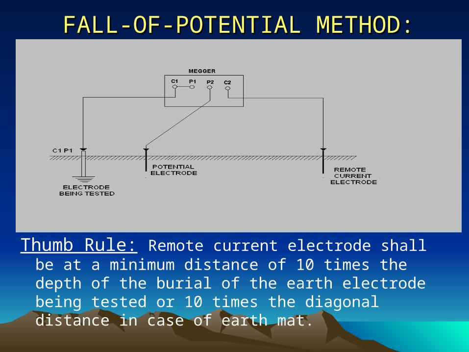
FALL-OF-POTENTIAL METHOD:FALL-OF-POTENTIAL METHOD:
Thumb Rule: Remote current electrode shall be at a minimum distance of 10 times the depth of the burial of the earth electrode being tested or 10 times the diagonal distance in case of earth mat.
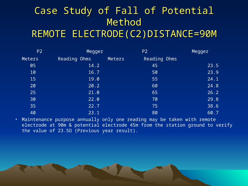
Case Study of Fall of Potential MethodCase Study of Fall of Potential MethodREMOTE ELECTRODE(C2)DISTANCE=90MREMOTE ELECTRODE(C2)DISTANCE=90M
P2 Megger P2 Megger
Meters Reading Ohms Meters Reading Ohms
05 14.2 45 23.5
10 16.7 50 23.9
15 19.0 55 24.1
20 20.2 60 24.8
25 21.0 65 26.2
30 22.0 70 29.8
35 22.7 75 38.6
40 23.1 80 60.7
• Maintenance purpose annually only one reading may be taken with remote electrode at 90m & potential electrode 45m from the station ground to verify the value of 23.5Ω (Previous year result).
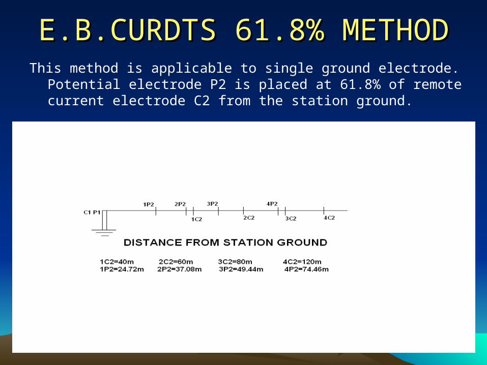
E.B.CURDTS 61.8% METHODE.B.CURDTS 61.8% METHODThis method is applicable to single ground electrode. Potential electrode
P2 is placed at 61.8% of remote current electrode C2 from the station ground.
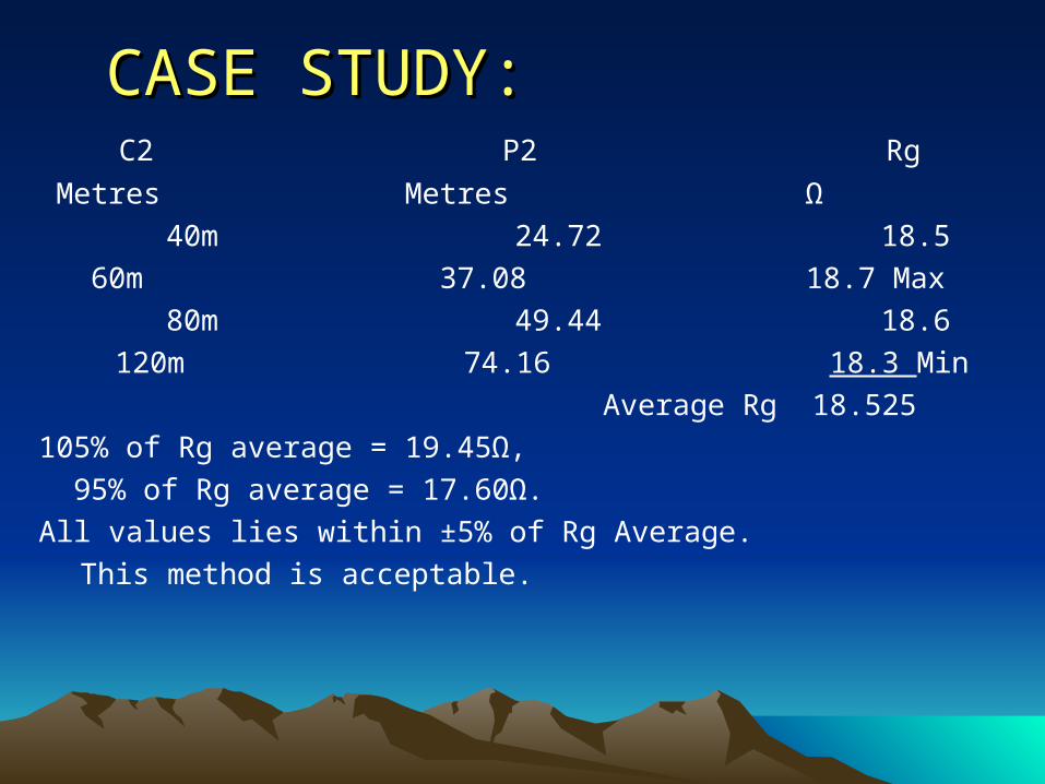
CASE STUDY:CASE STUDY: C2 P2 Rg
Metres Metres Ω
40m 24.72 18.5
60m 37.08 18.7 Max
80m 49.44 18.6
120m 74.16 18.3 Min
Average Rg 18.525
105% of Rg average = 19.45Ω,
95% of Rg average = 17.60Ω.
All values lies within ±5% of Rg Average.
This method is acceptable.
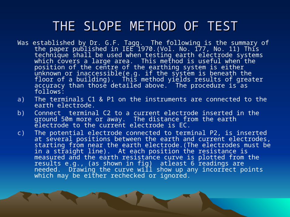
THE SLOPE METHOD OF TESTTHE SLOPE METHOD OF TESTWas established by Dr. G.F. Tagg. The following is the summary of the paper
published in IEE 1970.(Vol. No. 177, No. 11) This technique shall be used when testing earth electrode systems which covers a large area. This method is useful when the position of the centre of the earthing system is either unknown or inaccessible(e.g. if the system is beneath the floor of a building). This method yields results of greater accuracy than those detailed above. The procedure is as follows:
a) The terminals C1 & P1 on the instruments are connected to the earth electrode.
b) Connect terminal C2 to a current electrode inserted in the ground 50m more or away. The distance from the earth electrode to the current electrode is EC.
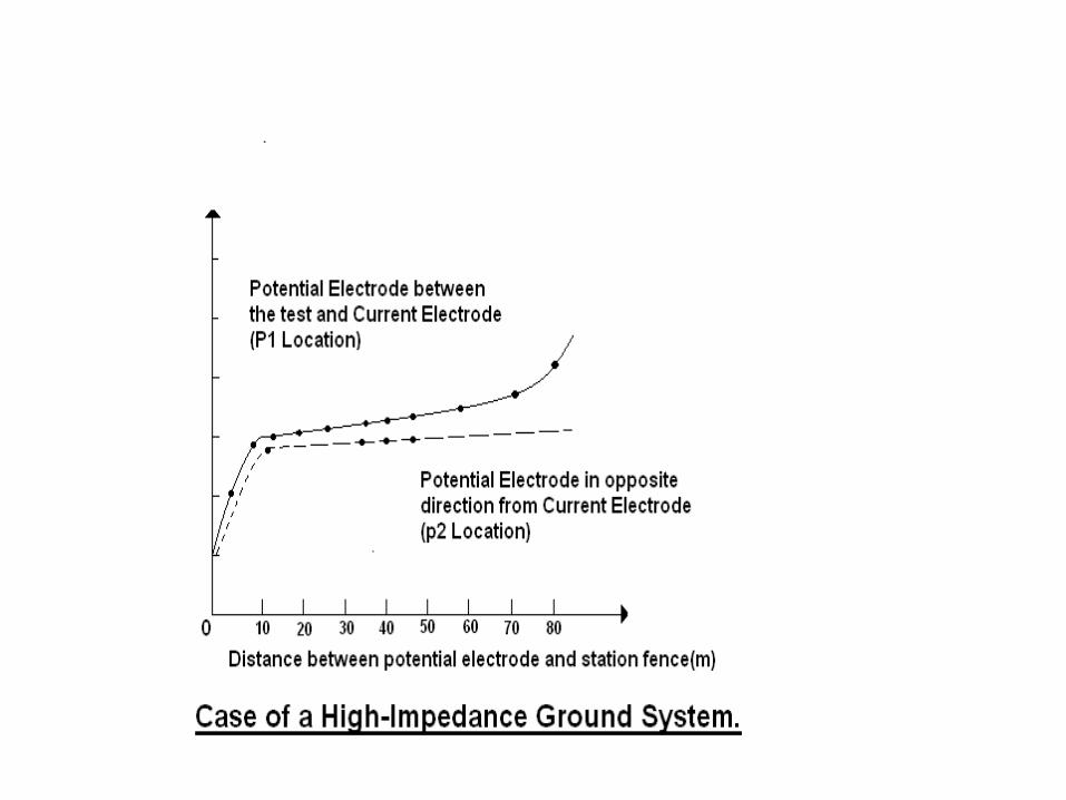
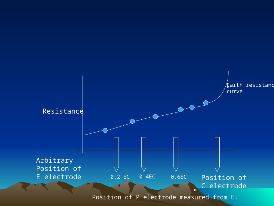
c) The potential electrode connected to terminal P2, is inserted at several positions between the earth and current electrodes, starting from near the earth electrode.(The electrodes must be in a straight line). At each position the resistance is measured and the earth resistance curve is plotted from the results e.g., (as shown in fig) atleast 6 readings are needed. Drawing the curve will show up any incorrect points which may be either rechecked or ignored.
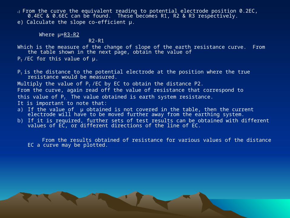
d) From the curve the equivalent reading to potential electrode position 0.2EC, 0.4EC & 0.6EC can be found. These becomes R1, R2 & R3 respectively.
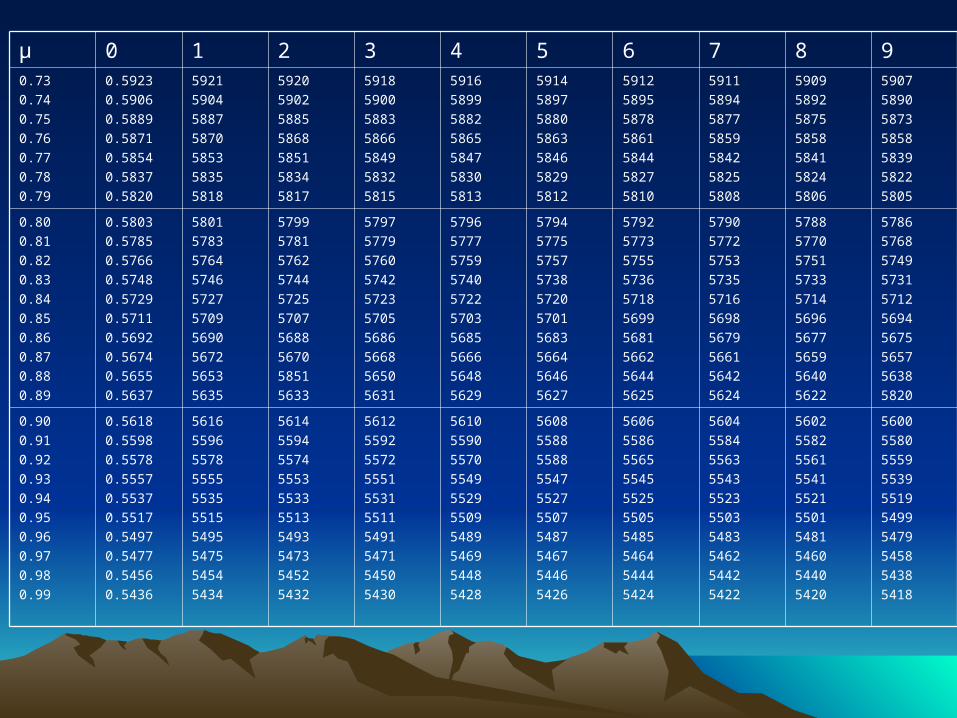
e) Calculate the slope co-efficient µ. Where µ=R3-R2 R2-R1Which is the measure of the change of slope of the earth resistance curve. From the table shown in the
next page, obtain the value of PT /EC for this value of µ.
PT is the distance to the potential electrode at the position where the true resistance would be measured. Multiply the value of PT /EC by EC to obtain the distance P2. From the curve, again read off the value of resistance that correspond tothis value of PT. The value obtained is earth system resistance. It is important to note that: a) If the value of µ obtained is not covered in the table, then the current electrode will have to be
moved further away from the earthing system. b) If it is required, further sets of test results can be obtained with different values of EC, or different
directions of the line of EC.
From the results obtained of resistance for various values of the distance EC a curve may be plotted.
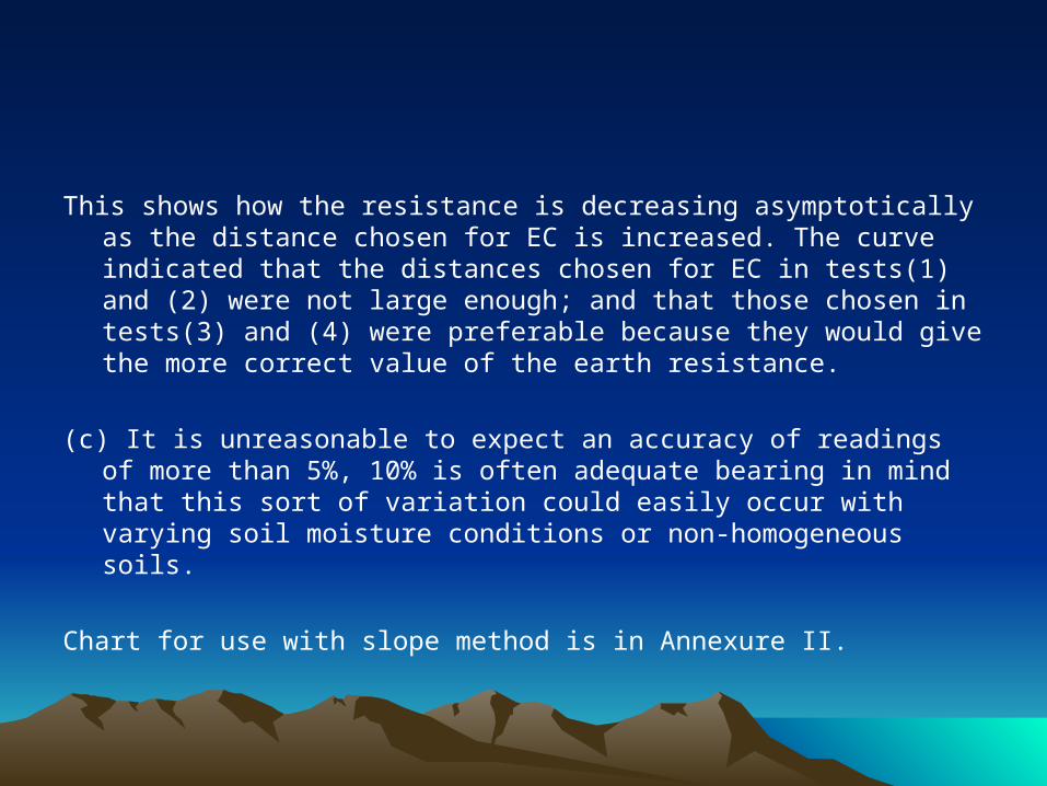
This shows how the resistance is decreasing asymptotically as the distance chosen for EC is increased. The curve indicated that the distances chosen for EC in tests(1) and (2) were not large enough; and that those chosen in tests(3) and (4) were preferable because they would give the more correct value of the earth resistance.
(c) It is unreasonable to expect an accuracy of readings of more than 5%, 10% is often adequate bearing in mind that this sort of variation could easily occur with varying soil moisture conditions or non-homogeneous soils.
Chart for use with slope method is in Annexure II.
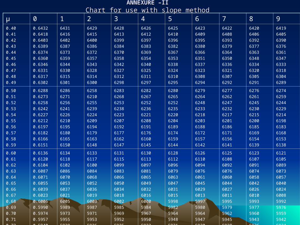
ANNEXURE –IIANNEXURE –IIChart for use with slope methodChart for use with slope method
µ 0 1 2 3 4 5 6 7 8 90.40
0.41
0.42
0.43
0.44
0.45
0.46
0.47
0.48
0.49
0.6432
0.6418
0.6403
0.6389
0.6374
0.6360
0.6346
0.6331
0.6317
0.6302
6431
6416
6402
6387
6373
6359
6344
6330
6315
6301
6429
6415
6400
6386
6372
6357
6343
6328
6314
6300
6428
6413
6399
6384
6370
6358
6342
6327
6312
6298
6426
6412
6397
6383
6369
6354
6340
6325
6311
6297
6425
6410
6396
6382
6367
6353
6338
6324
6310
6295
6423
6409
6395
6380
6366
6351
6337
6323
6308
6294
6422
6408
6393
6379
6364
6350
6336
6321
6307
6292
6420
6406
6392
6377
6363
6348
6334
6320
6305
6291
6419
6405
6390
6376
6361
6347
6333
6318
6304
6289
0.50
0.51
0.52
0.53
0.54
0.55
0.56
0.57
0.58
0.59
0.6288
0.6273
0.6258
0.6242
0.6227
0.6212
0.6197
0.6182
0.6166
0.6151
6286
6271
6256
6241
6226
6210
6195
6180
6165
6150
6258
6210
6255
6239
6224
6209
6194
6179
6163
6148
6283
6268
6253
6238
6223
6207
6192
6177
6162
6147
6282
6267
6252
6236
6221
6208
6191
6176
6160
6145
6280
6265
6252
6235
6220
6204
6189
6174
6159
6144
6279
6264
6248
6233
6218
6203
6188
6172
6157
6142
6277
6262
6247
6232
6217
6201
6186
6171
6156
6141
6276
6261
6245
6230
6215
6200
6185
6169
6154
6139
6274
6259
6244
6229
6214
6198
6183
6168
6153
6138
0.60
0.61
0.62
0.63
0.64
0.65
0.66
0.67
0.68
0.69
0.70
0.71
0.72
0.6136
0.6120
0.6104
0.6087
0.6071
0.6055
0.6039
0.6023
0.6006
0.5990
0.5974
0.5957
0.5940
6134
6118
6102
6086
6070
6053
6037
6021
6005
5989
5973
5955
5938
6133
6117
6100
6084
6068
6052
6036
6019
6003
5987
5971
5953
5936
6131
6115
6099
6083
6066
6050
6034
6018
6002
5985
5969
5952
5935
6130
6113
6097
6081
6065
6049
6032
6016
6000
5984
5967
5950
5933
6128
6112
6096
6079
6063
6047
6031
6015
5998
5982
5964
5948
5931
6126
6110
6094
6076
6061
6045
6029
6013
5997
5980
5964
5947
5930
6125
6108
6092
6076
6060
6044
6027
6011
5995
5979
5962
5945
5928
6123
6107
6091
6074
6058
6042
6026
6010
5993
5977
5960
5943
5926
6121
6105
6089
6073
6057
6040
6024
6008
5992
5976
5959
5942
5924
µ 0 1 2 3 4 5 6 7 8 90.73
0.74
0.75
0.76
0.77
0.78
0.79
0.5923
0.5906
0.5889
0.5871
0.5854
0.5837
0.5820
5921
5904
5887
5870
5853
5835
5818
5920
5902
5885
5868
5851
5834
5817
5918
5900
5883
5866
5849
5832
5815
5916
5899
5882
5865
5847
5830
5813
5914
5897
5880
5863
5846
5829
5812
5912
5895
5878
5861
5844
5827
5810
5911
5894
5877
5859
5842
5825
5808
5909
5892
5875
5858
5841
5824
5806
5907
5890
5873
5858
5839
5822
5805
0.80
0.81
0.82
0.83
0.84
0.85
0.86
0.87
0.88
0.89
0.5803
0.5785
0.5766
0.5748
0.5729
0.5711
0.5692
0.5674
0.5655
0.5637
5801
5783
5764
5746
5727
5709
5690
5672
5653
5635
5799
5781
5762
5744
5725
5707
5688
5670
5851
5633
5797
5779
5760
5742
5723
5705
5686
5668
5650
5631
5796
5777
5759
5740
5722
5703
5685
5666
5648
5629
5794
5775
5757
5738
5720
5701
5683
5664
5646
5627
5792
5773
5755
5736
5718
5699
5681
5662
5644
5625
5790
5772
5753
5735
5716
5698
5679
5661
5642
5624
5788
5770
5751
5733
5714
5696
5677
5659
5640
5622
5786
5768
5749
5731
5712
5694
5675
5657
5638
5820
0.90
0.91
0.92
0.93
0.94
0.95
0.96
0.97
0.98
0.99
0.5618
0.5598
0.5578
0.5557
0.5537
0.5517
0.5497
0.5477
0.5456
0.5436
5616
5596
5578
5555
5535
5515
5495
5475
5454
5434
5614
5594
5574
5553
5533
5513
5493
5473
5452
5432
5612
5592
5572
5551
5531
5511
5491
5471
5450
5430
5610
5590
5570
5549
5529
5509
5489
5469
5448
5428
5608
5588
5588
5547
5527
5507
5487
5467
5446
5426
5606
5586
5565
5545
5525
5505
5485
5464
5444
5424
5604
5584
5563
5543
5523
5503
5483
5462
5442
5422
5602
5582
5561
5541
5521
5501
5481
5460
5440
5420
5600
5580
5559
5539
5519
5499
5479
5458
5438
5418

µ 0 1 2 3 4 5 6 7 8 91.30
1.31
1.32
1.33
1.34
1.35
1.36
1.37
1.38
1.39
0.4652
0.4618
0.4583
0.4549
0.4515
0.4481
0.4446
0.4412
0.4378
0.4343
4649
4614
4580
4546
4511
4477
4443
4408
4374
4340
4645
4611
4577
4542
4508
4474
4439
4405
4371
4336
4642
4607
4573
4539
4505
4470
4436
4402
4367
4333
4638
4604
4570
4535
4501
4467
4432
4398
4364
4330
4635
4601
4566
4532
4498
4463
4429
4395
4360
4326
4631
4597
4563
4529
4494
4460
4426
4391
4357
4323
4628
4594
4559
4525
4491
4457
4422
4388
4354
4319
4625
4590
4556
4522
4487
4453
4419
4384
4350
4316
4621
4586
4553
4518
4484
4450
4415
4381
4347
4312
1.40
1.41
1.42
1.43
1.44
1.45
1.46
1.47
1.48
1.49
0.4309
0.4267
0.4225
0.4183
0.4141
0.4099
0.4056
0.4014
0.3972
0.3930
4305
4263
4221
4178
4136
4094
4052
4010
3968
3926
4301
4258
4216
4174
4132
4090
4048
4005
3964
3921
4296
4254
4212
4170
4128
4086
4044
4001
3959
3917
4292
4250
4208
4166
4124
4082
4040
3997
3955
3913
4288
4246
4204
4162
4120
4077
4035
3993
3951
3909
4284
4242
4200
4157
4115
4073
4031
3989
3947
3905
4280
4237
4195
4153
4111
4069
4027
3985
3943
3900
4275
4233
4191
4149
4107
4065
4023
3980
3938
3896
4271
4229
4187
4145
4103
4061
4018
3976
3934
3892
1.50
1.51
1.52
1.53
1.54
1.55
1.56
1.57
1.58
1.59
0.3888
0.3840
0.3791
0.3740
0.3688
0.3635
0.3580
0.3523
0.3465
0.3405
3883
3835
3786
3735
3683
3630
3574
3517
3459
3399
3878
3830
3781
3730
3677
3624
3569
3511
3453
3393
3874
3825
3778
3724
3672
3619
3563
3506
3447
3386
3869
3820
3771
3719
3667
3613
3557
3500
3441
3380
3864
3818
3766
3714
3662
3608
3552
3494
3435
3374
3859
3811
3760
3709
3656
3602
3546
3488
3429
3368
3854
3808
3755
3704
3651
3597
3540
3482
3423
3362
3850
3801
3750
3698
3646
3591
3534
3477
3417
3355
3845
3796
3745
3693
3640
3586
3528
3471
3411
3349

µ 0 1 2 3 4 5 6 7 8 91.00
1.01
1.02
1.03
1.04
1.05
1.06
1.07
1.08
1.09
0.5416
0.5394
0.5371
0.5349
0.5327
0.5305
0.5282
0.5260
0.5238
0.5215
5414
5391
5369
5347
5325
5303
5280
5258
5235
5213
5412
5389
5367
5345
5322
5300
5278
5255
5233
5211
5409
5387
5365
5344
5320
5298
5276
5253
5231
5209
5407
5385
5362
5340
5318
5296
5273
5251
5229
5206
5405
5383
5360
5338
5316
5293
5271
5249
5229
5204
5403
5380
5358
5336
5313
5291
5269
5247
5224
5202
5400
5378
5356
5333
5311
5289
5267
5244
5222
5200
5398
5376
5354
5331
5309
5287
5264
5242
5219
5297
5396
5374
5351
5329
5307
5284
5262
5240
5217
5295
1.10
1.11
1.12
1.13
1.14
1.15
1.16
1.17
1.18
1.19
0.5193
0.5168
0.5143
0.5118
0.5093
0.5068
0.5042
0.5017
0.4992
0.4967
5190
5165
5140
5115
5090
5065
5040
5015
4990
4965
5188
5163
5137
5113
5088
5062
5037
5012
4987
4962
5185
5160
5135
5110
5085
5060
5035
5010
4985
4960
5183
5158
5132
5108
5083
5057
5032
5007
4982
4957
5180
5155
5130
5105
5080
5055
5030
5005
4980
4955
5178
5153
5127
5103
5078
5052
5027
5002
4977
4952
5175
5150
5125
5100
5075
5050
5025
5000
4975
4950
5173
5148
5122
5098
5073
5047
5022
4997
4972
4947
5170
5145
5120
5095
5070
5045
5020
4995
4970
4945
1.20
1.21
1.22
1.23
1.24
1.25
1.26
1.27
1.28
1.29
0.4942
0.4913
0.4884
0.4855
0.4826
0.4797
0.4768
0.4739
0.4710
0.4681
4939
4910
4881
4852
4823
4794
4765
4736
4707
4678
4936
4907
4878
4849
4820
4791
4762
4733
4704
4675
4933
4904
4875
4846
4817
4788
4759
4730
4701
4672
4930
4901
4872
4843
4814
4785
4756
4727
4698
4669
4928
4899
4870
4841
4812
4783
4754
4725
4696
4667
4925
4896
4867
4838
4809
4780
4751
4722
4693
4664
4922
4893
4864
4835
4808
4777
4748
4719
4690
4661
4919
4890
4861
4832
4803
4774
4745
4718
4687
4658
4916
4887
4858
4829
4800
4771
4742
4713
4684
4655
Earth resistancecurve
Resistance
ArbitraryPosition of E electrode 0.2 EC 0.4EC 0.6EC Position of
C electrode
Position of P electrode measured from E.
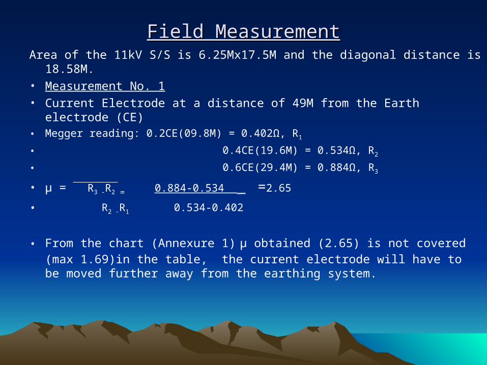
Field MeasurementField MeasurementArea of the 11kV S/S is 6.25Mx17.5M and the diagonal distance is 18.58M.• Measurement No. 1• Current Electrode at a distance of 49M from the Earth electrode (CE) • Megger reading: 0.2CE(09.8M) = 0.402Ω, R1
• 0.4CE(19.6M) = 0.534Ω, R2
• 0.6CE(29.4M) = 0.884Ω, R3
• µ = R3 -R2 = 0.884-0.534 =2.65
• R2 -R1 0.534-0.402
• From the chart (Annexure 1) µ obtained (2.65) is not covered (max 1.69)in the table, the current electrode will have to be moved further away from the earthing system.
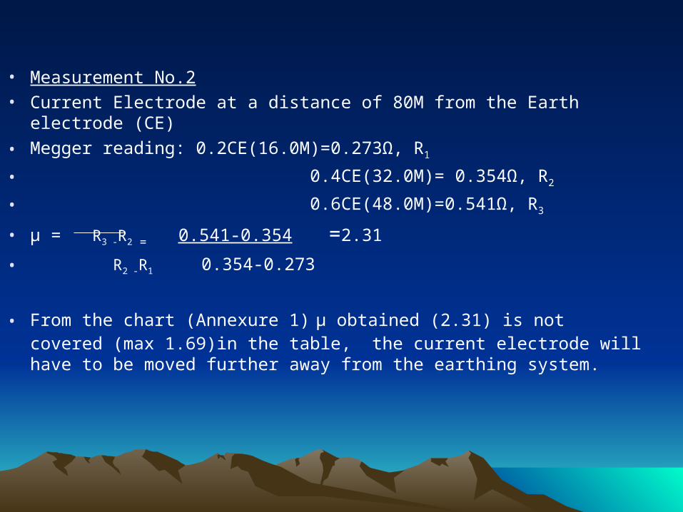
• Measurement No.2• Current Electrode at a distance of 80M from the Earth electrode (CE)
• Megger reading: 0.2CE(16.0M)=0.273Ω, R1
• 0.4CE(32.0M)= 0.354Ω, R2
• 0.6CE(48.0M)=0.541Ω, R3
• µ = R3 -R2 = 0.541-0.354 =2.31
• R2 -R1 0.354-0.273
• From the chart (Annexure 1) µ obtained (2.31) is not covered (max 1.69)in the table, the current electrode will have to be moved further away from the earthing system.
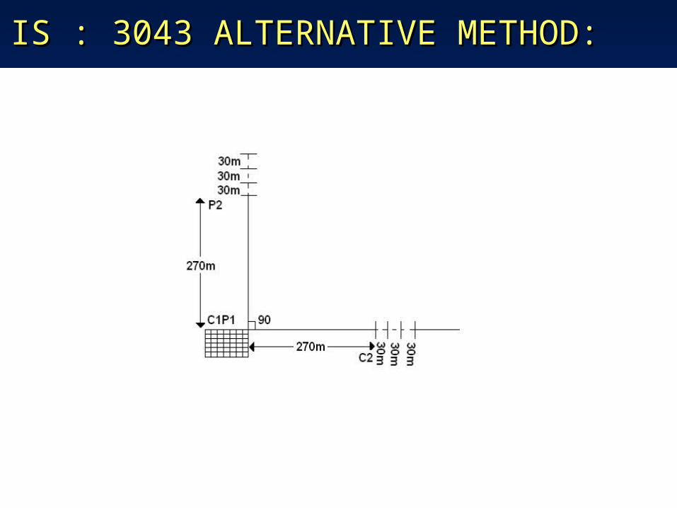
IS : 3043 ALTERNATIVE METHOD:IS : 3043 ALTERNATIVE METHOD:
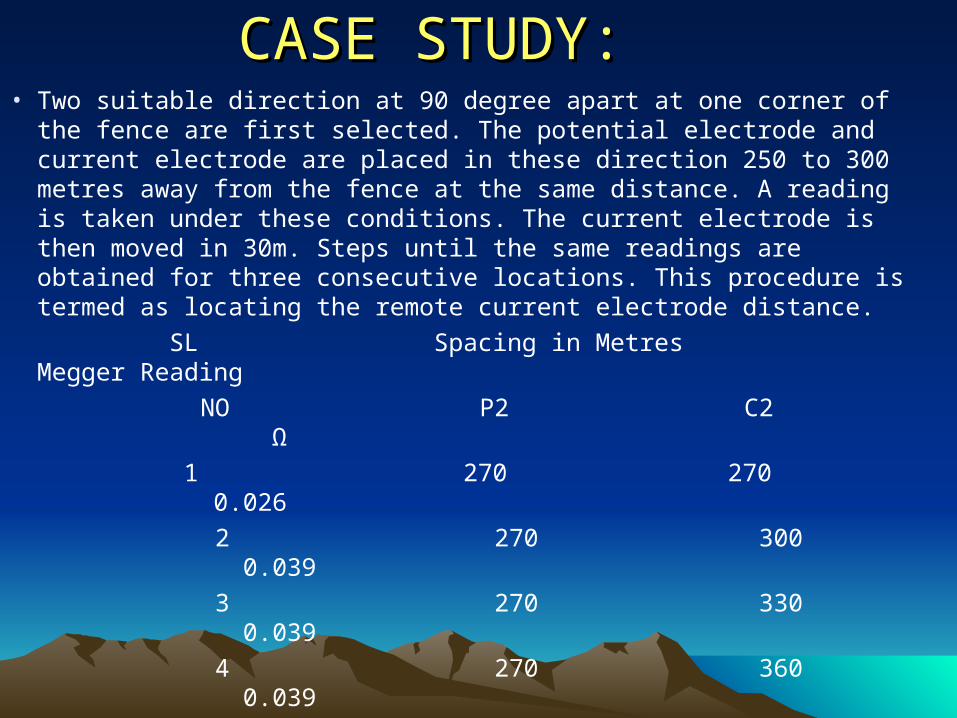
CASE STUDY:CASE STUDY:• Two suitable direction at 90 degree apart at one corner of the
fence are first selected. The potential electrode and current electrode are placed in these direction 250 to 300 metres away from the fence at the same distance. A reading is taken under these conditions. The current electrode is then moved in 30m. Steps until the same readings are obtained for three consecutive locations. This procedure is termed as locating the remote current electrode distance.
SL Spacing in Metres Megger Reading
NO P2 C2 Ω
1 270 270 0.026
2 270 300 0.039
3 270 330 0.039
4 270 360 0.039
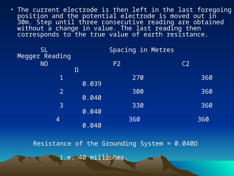
• The current electrode is then left in the last foregoing position and the potential electrode is moved out in 30m. Step until three consecutive reading are obtained without a change in value. The last reading then corresponds to the true value of earth resistance.
SL Spacing in Metres Megger Reading
NO P2 C2 Ω 1 270 360 0.039 2 300 360 0.040 3 330 360 0.040 4 360 360 0.040
Resistance of the Grounding System = 0.040Ω i.e. 40 milliohms.
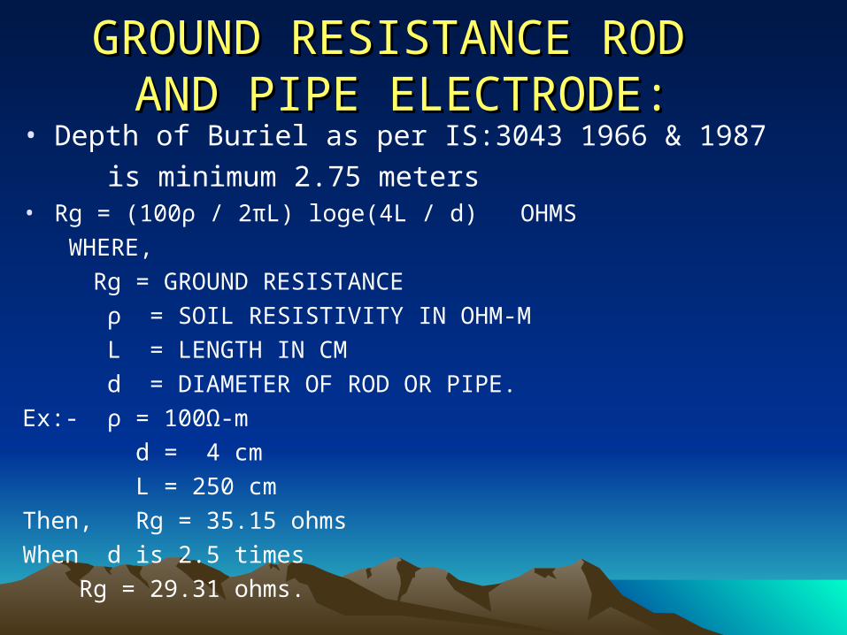
GROUND RESISTANCE ROD GROUND RESISTANCE ROD AND PIPE ELECTRODE:AND PIPE ELECTRODE:
• Depth of Buriel as per IS:3043 1966 & 1987
is minimum 2.75 meters • Rg = (100ρ / 2πL) loge(4L / d) OHMS
WHERE,
Rg = GROUND RESISTANCE
ρ = SOIL RESISTIVITY IN OHM-M
L = LENGTH IN CM
d = DIAMETER OF ROD OR PIPE.
Ex:- ρ = 100Ω-m
d = 4 cm
L = 250 cm
Then, Rg = 35.15 ohms
When d is 2.5 times
Rg = 29.31 ohms.
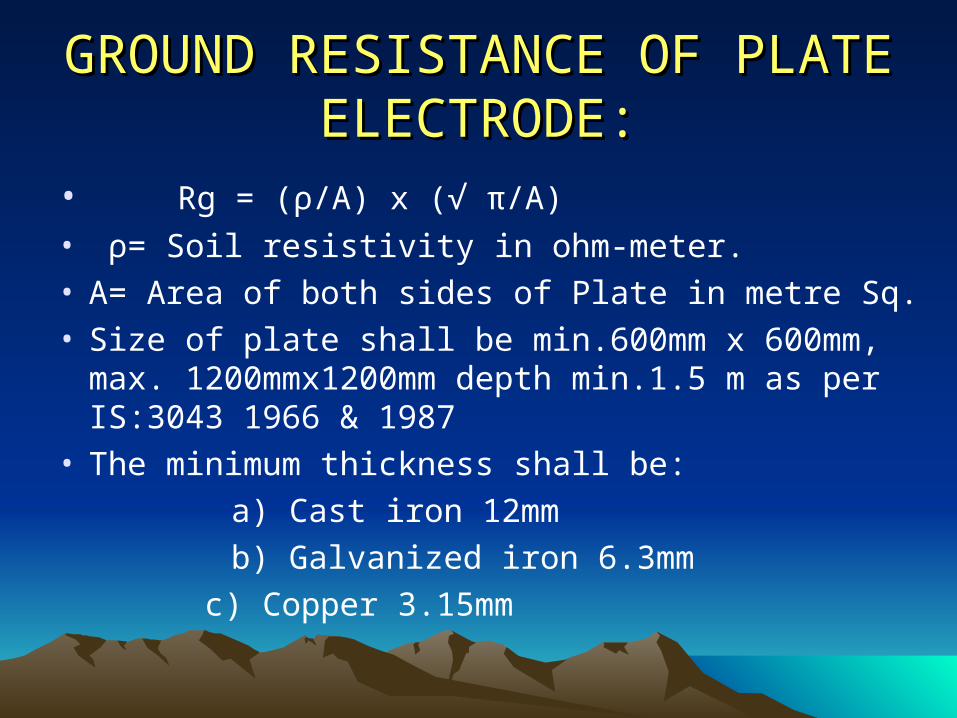
GROUND RESISTANCE OF GROUND RESISTANCE OF PLATE ELECTRODE:PLATE ELECTRODE:
• Rg = (ρ/A) x (√ π/A)
• ρ= Soil resistivity in ohm-meter.• A= Area of both sides of Plate in metre Sq.• Size of plate shall be min.600mm x 600mm, max.
1200mmx1200mm depth min.1.5 m as per IS:3043 1966 & 1987
• The minimum thickness shall be:
a) Cast iron 12mm
b) Galvanized iron 6.3mm
c) Copper 3.15mm
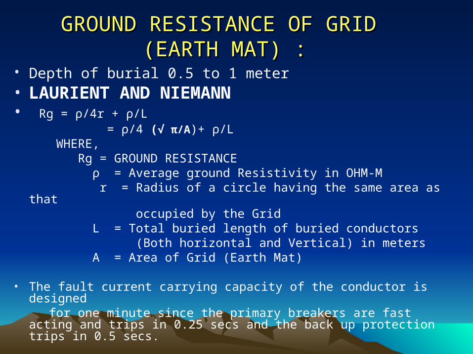
GROUND RESISTANCE OF GRID GROUND RESISTANCE OF GRID (EARTH MAT) :(EARTH MAT) :
• Depth of burial 0.5 to 1 meter • LAURIENT AND NIEMANN • Rg = ρ/4r + ρ/L = ρ/4 (√ π/A)+ ρ/L WHERE, Rg = GROUND RESISTANCE ρ = Average ground Resistivity in OHM-M r = Radius of a circle having the same area as that occupied by the Grid L = Total buried length of buried conductors (Both horizontal and Vertical) in meters A = Area of Grid (Earth Mat)
• The fault current carrying capacity of the conductor is designed for one minute since the primary breakers are fast acting and trips in
0.25 secs and the back up protection trips in 0.5 secs.
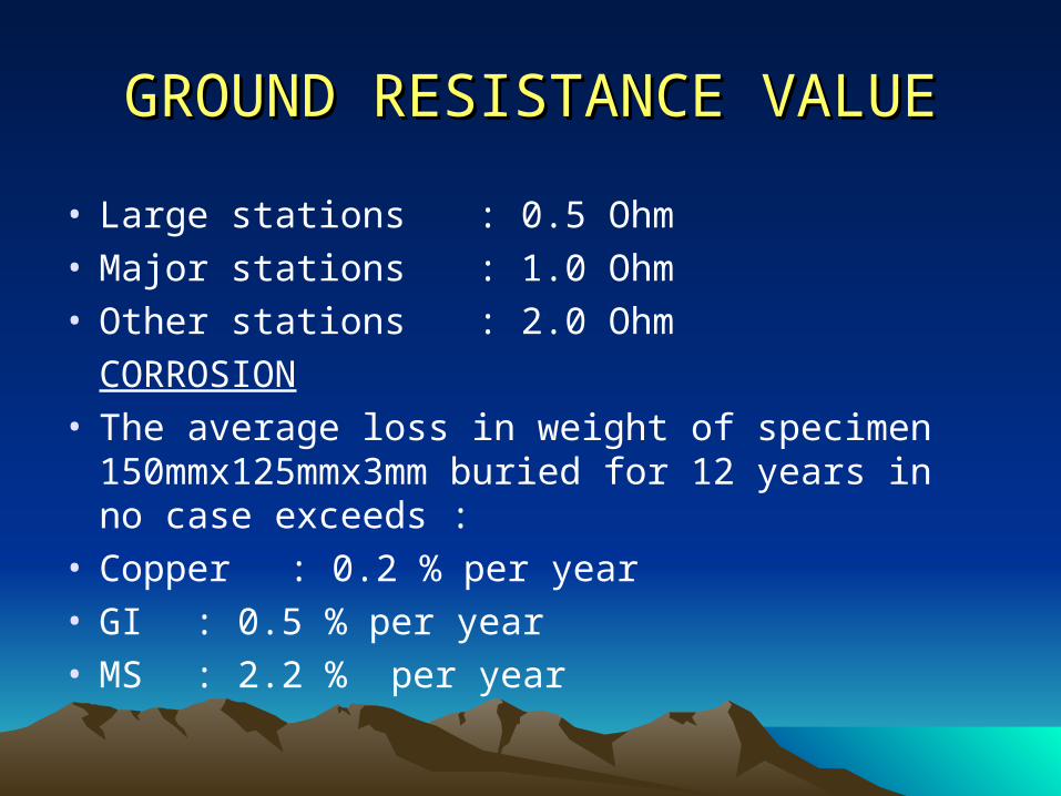
GROUND RESISTANCE VALUEGROUND RESISTANCE VALUE
• Large stations : 0.5 Ohm• Major stations : 1.0 Ohm• Other stations : 2.0 Ohm
CORROSION• The average loss in weight of specimen
150mmx125mmx3mm buried for 12 years in no case exceeds :
• Copper : 0.2 % per year• GI : 0.5 % per year• MS : 2.2 % per year
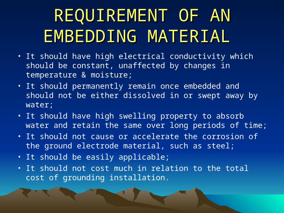
REQUIREMENT OF AN REQUIREMENT OF AN EMBEDDING MATERIALEMBEDDING MATERIAL
• It should have high electrical conductivity which should be constant, unaffected by changes in temperature & moisture;
• It should permanently remain once embedded and should not be either dissolved in or swept away by water;
• It should have high swelling property to absorb water and retain the same over long periods of time;
• It should not cause or accelerate the corrosion of the ground electrode material, such as steel;
• It should be easily applicable;• It should not cost much in relation to the total cost of
grounding installation.
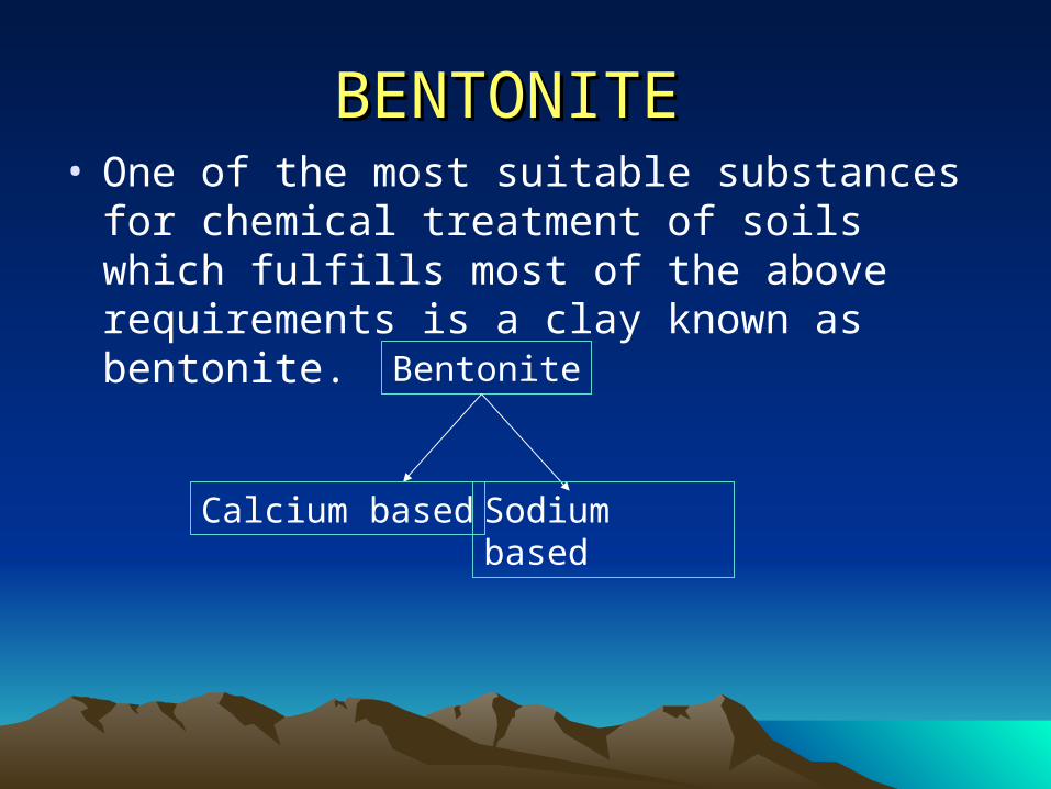
BENTONITE BENTONITE • One of the most suitable substances for
chemical treatment of soils which fulfills most of the above requirements is a clay known as bentonite.
Bentonite
Calcium based Sodium based
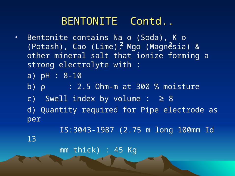
BENTONITE Contd..BENTONITE Contd..
• Bentonite contains Na o (Soda), K o (Potash), Cao (Lime), Mgo (Magnesia) & other mineral salt that ionize forming a strong electrolyte with :
a) pH : 8-10
b) ρ : 2.5 Ohm-m at 300 % moisture
c) Swell index by volume : ≥ 8
d) Quantity required for Pipe electrode as per
IS:3043-1987 (2.75 m long 100mm Id 13
mm thick) : 45 Kg
2 2
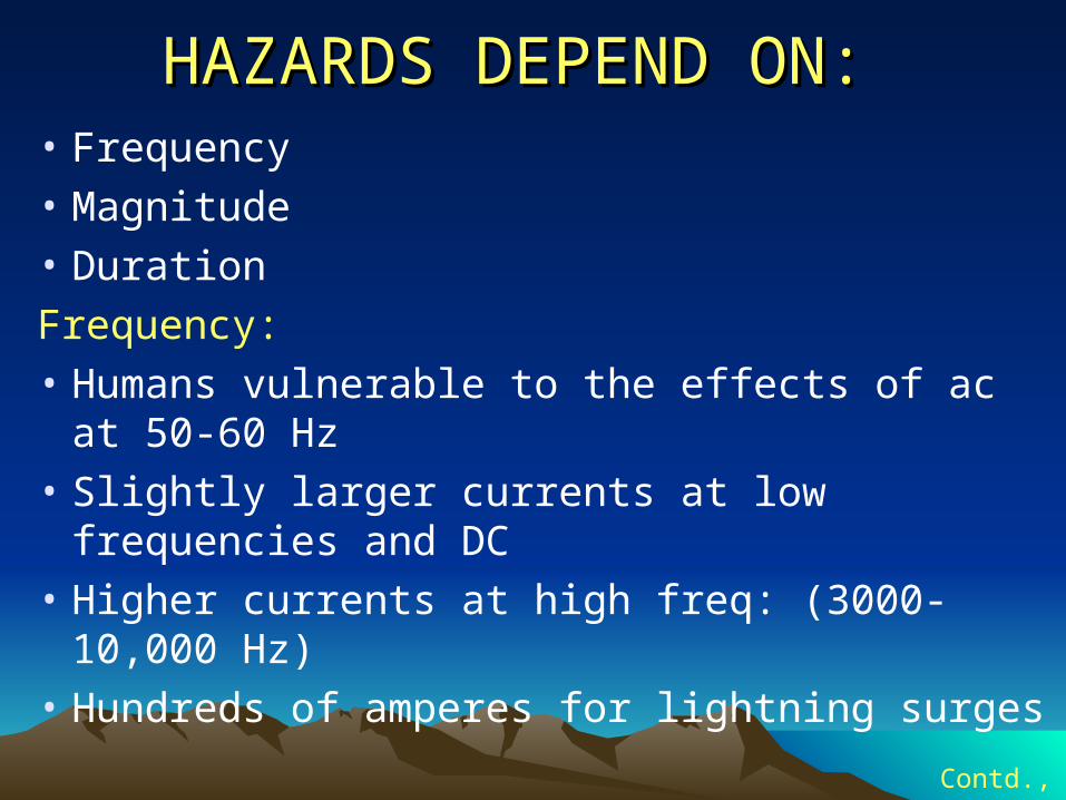
HAZARDS DEPEND ON:HAZARDS DEPEND ON: • Frequency
• Magnitude
• Duration
Frequency:
• Humans vulnerable to the effects of ac at 50-60 Hz
• Slightly larger currents at low frequencies and DC
• Higher currents at high freq: (3000-10,000 Hz)
• Hundreds of amperes for lightning surgesContd.,
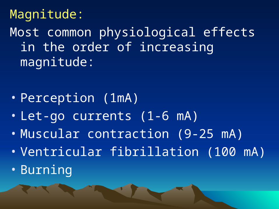
Magnitude:
Most common physiological effects in the order of increasing magnitude:
• Perception (1mA)
• Let-go currents (1-6 mA)
• Muscular contraction (9-25 mA)
• Ventricular fibrillation (100 mA)
• Burning
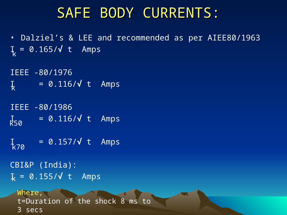
SAFE BODY CURRENTS:SAFE BODY CURRENTS: • Dalziel’s & LEE and recommended as per AIEE80/1963
I = 0.165/√ t Amps
IEEE -80/1976
I = 0.116/√ t Amps
IEEE -80/1986
I = 0.116/√ t Amps
I = 0.157/√ t Amps
CBI&P (India):
I = 0.155/√ t Amps
k
Where,t=Duration of the shock 8 ms to 3 secs
k50
k70
k
k
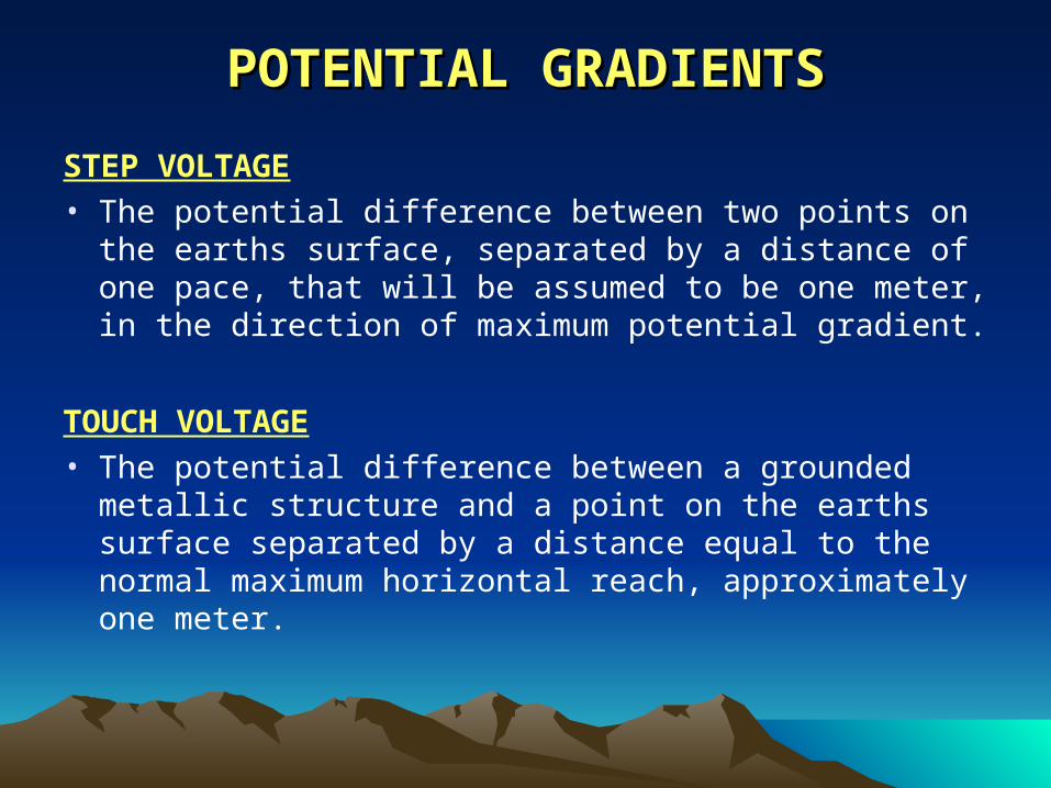
POTENTIAL GRADIENTSPOTENTIAL GRADIENTS
STEP VOLTAGE• The potential difference between two points on the
earths surface, separated by a distance of one pace, that will be assumed to be one meter, in the direction of maximum potential gradient.
TOUCH VOLTAGE• The potential difference between a grounded metallic
structure and a point on the earths surface separated by a distance equal to the normal maximum horizontal reach, approximately one meter.
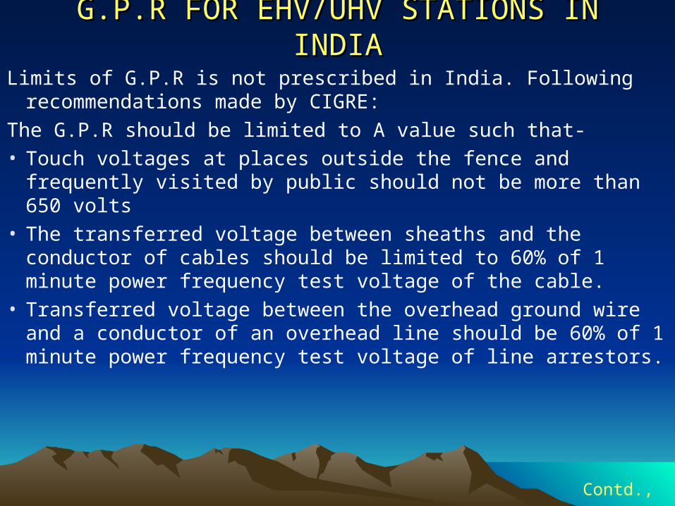
G.P.R FOR EHV/UHV STATIONS IN INDIAG.P.R FOR EHV/UHV STATIONS IN INDIA
Limits of G.P.R is not prescribed in India. Following recommendations made by CIGRE:
The G.P.R should be limited to A value such that-• Touch voltages at places outside the fence and frequently
visited by public should not be more than 650 volts• The transferred voltage between sheaths and the conductor of
cables should be limited to 60% of 1 minute power frequency test voltage of the cable.
• Transferred voltage between the overhead ground wire and a conductor of an overhead line should be 60% of 1 minute power frequency test voltage of line arrestors.
Contd.,
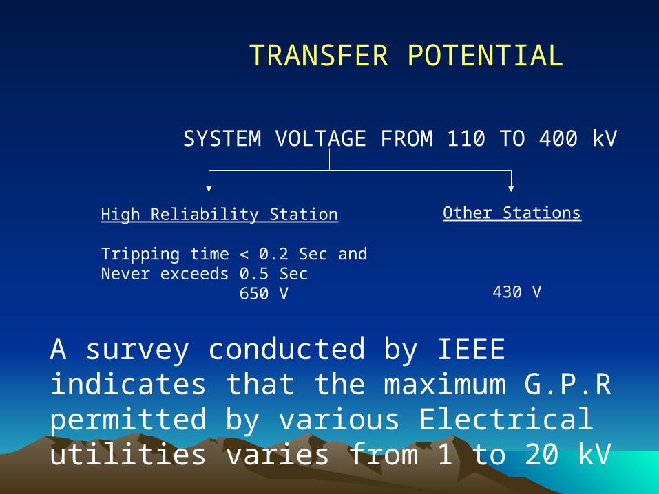
TRANSFER POTENTIAL
SYSTEM VOLTAGE FROM 110 TO 400 kV
High Reliability Station
Tripping time 0.2 Sec and Never exceeds 0.5 Sec 650 V
Other Stations
430 V
A survey conducted by IEEE indicates that the maximum G.P.R permitted by various Electrical utilities varies from 1 to 20 kV
MAINTENANCEMAINTENANCE• Maintenance of earth-electrodes at power stations and
substations
• Records should be kept of the initial resistance of power station and substation earth-electrode systems and of subsequent tests carried out. Such tests should be made periodically to ensure that no serious increase in resistance occurs. Normally an annual test should suffice, but local circumstances may justify an increase or reduction in the intervals between tests in the light of experience. Where possible earth-electrodes should be arranged in groups so that they can be disconnected in turn from the general earthing system for test while leaving sufficient electrodes in service to provide an effective connection with earth.
MAINTENANCE Contd..MAINTENANCE Contd..• In urban substations it is frequently impossible to make any effective
check on the resistance to general mass of earth of the electrode system because of the connection to the metallic sheaths of numerous high voltage and low voltage cables. In such cases, the earthing connections within the substations should permit periodical and visual inspection.
• In rural substations, particularly those connected to overhead high voltage and low voltage lines, greater reliance needs to be placed on the electrode system, and it is important that there should be facilities for testing the resistance of the electrode to general mass of earth. Normally annual measurements shall be carried out but local circumstances in the light of experience may justify increase or decrease in this interval but it should not be less than once in two years.
PRECAUTIONS TO BE TAKEN DURING PRECAUTIONS TO BE TAKEN DURING RESISTANCE MEASUREMENTSRESISTANCE MEASUREMENTS
• There is a possibility of lethal potential existing between a station ground and a remote ground if a system fault involving the station ground occurs while ground resistance is being measured. The use of rubber gloves is advisable while making connections to the test electrodes. Under no circumstances should the two hands or other parts of the body of the testing personal should be allowed to complete the circuit between the points of possible high potential difference.
• An isolated lightning arrester ground should never be tested with the arrestor in service because of the possible high potential gradient around the ground connection.
• Since the resistivity of the upper soil layers is greatly influenced by the weather, a day test should be chosen which is free from extreme weather conditions.
SUPPLIERS OF EARTH TESTERSSUPPLIERS OF EARTH TESTERS M/s Ashida Electronics
Ram Rajya, Kopri Thane – 400 603, Maharastra
M/s Agarwal Electronics201, Shivashakthi Indus. Estate,Near Shreyas Talkies, LBS MargGhatkopar (w), Bombay – 400 086
M/s Cambride Instruments and Engg.company23/2, Maulana Abdul kalam azad Road,Howrah – 711 001, West Bengal
M/s Conin Prakriti InstrumentationREGD.Off & Facty.16, Ragendra Nagar Industrial Estate,P.O.Mohan nagar, Ghaziabad 201 007
M/s Continental Electronics Naroda177/4, Industrial Estate,Naroda -382 380, Dist.AhmedabadGujarat
M/s Erricson EngineersUnigue House, 11th Floor,25, Parsee Bazaar streetBombay-400 023 Contd.,
M/s Indotech Devices Pvt Ltd.,
H.O & works, A-75 Sector V
P.B.19, Noida 201 301
Dist.Ghaziabad, U.P
Instrument Techniques Pvt Ltd.,
Regd. Off & works B-2
Co-operative Industrial Estate,
Balanagar, Hyderabad – 500 037
Nippen Electric Instruments
Company Sett & of
12-A, Marol Maroshi Road,
Andheri (E), Bombay – 400 059
M/s Sharmasons sakova Instruments Pvt Ltd.,
P.B.No.6251, 2, OLF Industrial Area,
Najafgarh Road,
New Delhi 110 015
M/s W.J. Alcock & Co. Pvt Ltd.,
7, K.S.Roy Road,
Calcutta – 700 001
M/s Yokins Instruments
Yokin Trade Lines Admn.Office
B-3/40 Ashok Vihar Phase II, Delhi 110 052
BENTONITE SUPPLIERSBENTONITE SUPPLIERSM/s Amar minerals Pvt Ltd., Netivali Baug, KalyanDist.Thane, Maharastra
M/s Amarjyot IndustriesNo.45, Dr.Meisheri Road,Near Sandhurst road,Railway Stn.BombayWorks:A-108, MIDC, Dombivili, Dist.Thana
M/s Industrial Minerals & Chemicals Co.Pvt Ltd.,No.125, Narayan Dhauru street,Nagaevi, Bombay – 400 003Works: Kurla Road, chakala Andheri Bombay-58Works: Chinchpokli cross lane, Bomaby 400 027
M/s International Minerals & Chemicals Co.No.54-D, Govt.Industrial Estate,Bombay-400 067
M/s Ambika Minechem IndustriesNo.129/131, Kazi Sayed street4th Floor, Bombay – 400 003
Contd.,

M/s Mysore Agencies
23/1, 3 rd Cross, Lalbaugh Road,
Bangalore – 560 027
M/s Baroda Mineral Grinding Industries
National highway, Naroda Ahmedabad
M/s J.D.Jones & Co.Pvt Ltd.,
C/5, Gillander House,
No.8, Netaji Subhash Road,
Calcutta 700001
M/s Metamine Industries
Rathnagarmata Road,
Kapadvanj, Dist.Kaira
Gujarat
M/s Somanath Minerals & Chemicals
No.72, Chitra Industrial Estate,
Bhavnagar 364 004 (Gujarath)Contd.,

M/s Sunders India Corporation
Near Indian Airlines Corporation
Diwanpara Road, Bhavnagar – 364 001
M/s Manjunatha Pulverisers
Sabuvani Buildings
N.R.Road,
Bangalore – 560 002
M/s Mysore City & Mineral Industries
No.1032, IV Block, Rajaji nagar,
Bangalore 560 010
M/s Mine Chemical Industries,
Peenya Industrial Estate
Phase III, Bangalore
M/s Binto Plast Pvt Ltd.,
Industrial Estate,
Jodhpur – 342 001
Contd.,
M/s United Engineering Corporation
APSRTC Complex,
Vishakapatnam
M/s Ashapura Group of Industries
“ VIBHA” 55/3 13th H Main
HAL 2nd Stage Indira nagar,
Bangalore – 560 008
H.O.81/82, Mittal Court C
Nariman point,
Bombay – 400 021
M/s OSWAL MINERALS
No.6, 2nd Main Road,
Rama chandrapuram
Bangalore – 560 021
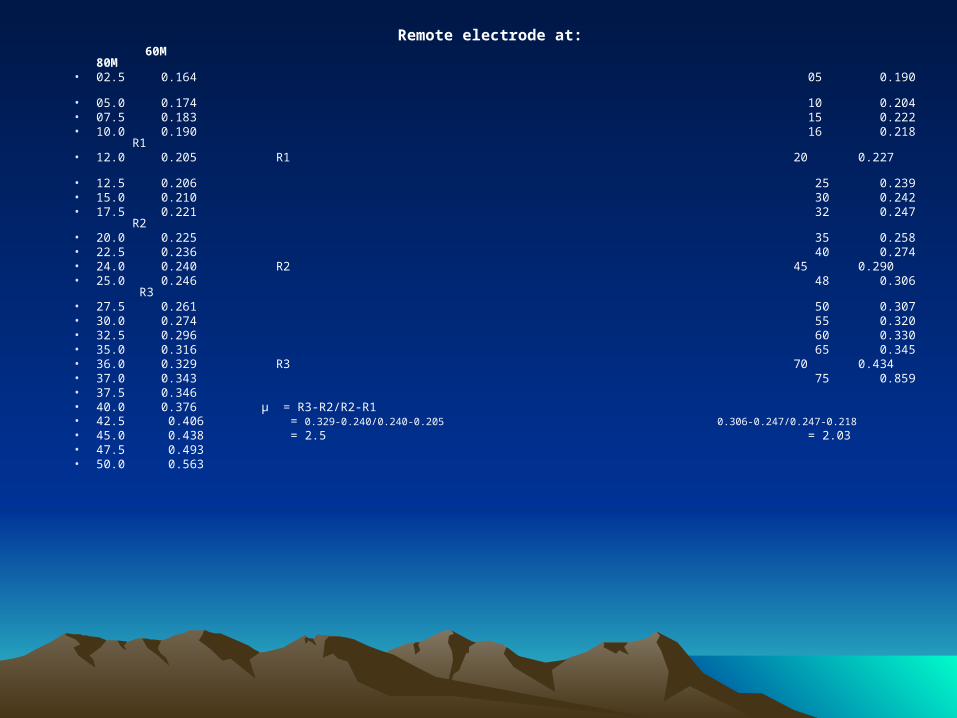
Remote electrode at: 60M 80M• 02.5 0.164 05 0.190 • 05.0 0.174 10 0.204 • 07.5 0.183 15 0.222• 10.0 0.190 16 0.218 R1 • 12.0 0.205 R1 20 0.227 • 12.5 0.206 25 0.239• 15.0 0.210 30 0.242• 17.5 0.221 32 0.247 R2 • 20.0 0.225 35 0.258• 22.5 0.236 40 0.274• 24.0 0.240 R2 45 0.290• 25.0 0.246 48 0.306 R3• 27.5 0.261 50 0.307• 30.0 0.274 55 0.320• 32.5 0.296 60 0.330• 35.0 0.316 65 0.345• 36.0 0.329 R3 70 0.434• 37.0 0.343 75 0.859• 37.5 0.346• 40.0 0.376 µ = R3-R2/R2-R1• 42.5 0.406 = 0.329-0.240/0.240-0.205 0.306-0.247/0.247-0.218• 45.0 0.438 = 2.5 = 2.03• 47.5 0.493• 50.0 0.563

THANK YOU