Embed Size (px)
Citation preview
Power transformer protection using S-transform withcomplex window and pattern recognition approach
S.R. Samantaray, B.K. Panigrahi, P.K. Dash and G. Panda
Abstract: A new approach for power transformer protection using S-transform with complexwindow to distinguish between inrush current and internal fault is presented. The S-transformwith complex window is used to extract patterns of transient current samples during inrush andfaults. S-transform is a very powerful tool for non-stationary signal analysis giving the informationof transient currents both in time and in frequency domains. The spectral energy is calculated forinrush and internal faults and an energy index is found out to distinguish between inrush magnetis-ing current and internal faults. The simulation results and the results obtained using real-time datafrom a transformer in the laboratory environment indicate the robustness of the proposed technique.
1 Introduction
Power transformers play a vital role in any electric powersystem network. So it is very important to avoid anymal-operation and false tripping by providing requiredrelaying system. Protection of large power transformers isa very challenging job in power system relaying. Thephenomenon of inrush current in the power transformershas been well known for many years and is an importantaspect of harmonic restraint differential relay. The inrushcurrent contains a large second harmonic component incomparison to an internal fault. Sometimes, the secondharmonic may be generated in the case of internal faultsin power transformer also. This may be due to current trans-former (CT) saturation and distributive capacitance in longtransmission line to which the power transformer is con-nected. In certain cases, the magnitude of second harmonicin an internal fault current can be close to or greater thanthat present in the magnetising inrush current. Moreover,the second harmonic components in the magnetisinginrush current tend to be relatively small in modern powertransformer because of design improvements. Thus, thecommonly employed conventional differential protectionbased on second harmonic restraint will face difficulty indistinguishing inrush current and internal faults. Thus, animproved technique of protection is required to discriminatebetween inrush current and internal faults.
As both inrush current and internal faults are non-stationary signals, the most important requirement is toextract features from the signal. For feature extraction orpattern recognition from non-stationary signal short timeFourier transform (STFT), discrete wavelet transform(DWT) has been used extensively. In the case of DWT[1, 2, 9, 10], the variations of the detailed coefficients are
# The Institution of Engineering and Technology 2007
doi:10.1049/iet-gtd:20060206
Paper first received 28th April 2005 and in revised form 25th August 2006
S.R. Samantaray and G. Panda are with the National Institute of Technology,Rourkela, India
B.K. Panigrahi is with the Indian Institute of Technology, New Delhi, India
P.K. Dash is with the Centre for Research in Electrical, Electronics andComputer Engineering, Bhubaneswar, India
E-mail: [email protected]
278
obtained to distinguish between magnetising inrush andfault. The wavelet transform specifically decomposes asignal from high frequency to low frequency bandsthrough an iterative procedure, and this procedure performsvery well for high-frequency transients but not so well forlow-frequency components including second-, third- andfifth-harmonic components of current present in the magne-tising inrush or faults. Consequently, the wavelet decompo-sition coefficients in a frequency band reflect the overalleffect of all signal components in the frequency band,rather than the specific fundamental and harmonic ones.Also the frequency properties of the decomposition filterbands are not ideal and suffer leakage effects where thesignal frequency is closer to the edge of a frequency band.Therefore a more suitable signal processing technique isconsidered in this paper for recognising the current signalpatterns in a transformer.
The S-transform is an invertible time–frequency spectrallocalisation technique [3–6] that combines elements ofwavelet transform and STFT. The S-transform uses ananalysis window whose width is decreasing with frequencyproviding a frequency-dependent resolution. S-transform isa continuous wavelet transform with a phase correction. Itproduces a constant relative bandwidth analysis like wave-lets, although maintains a direct link with Fourier spectrum.The S-transform has an advantage in that it providesmultiresolution analysis while retaining the absolute phaseof each frequency. This has led to its application for detectionand interpretation of non-stationary signals. Further, theS-transform provides frequency contours which clearlylocalises the signals at a higher noise level [7]. Inthis paper, a new pattern recognition approach usingS-transform with complex window [8] is presented to dis-tinguish between inrush and fault currents. As S-transformis obtained by multiplying the real window with Fouriersinusoid and Fourier sinusoid has time-invariant frequency,S-transform is unsuitable for resolving waveforms whosefrequency changes with time. This problem can be overcomeby using complex Gaussian window with a user-designedcomplex phase function. The phase function modulates thefrequency of the Fourier sinusoid to give better time–frequency localisation of the time series. That means if thetime series contains a specific asinusoidal waveform that isexpected at all scales, then the complex Gaussian window
IET Gener. Transm. Distrib., 2007, 1, (2), pp. 278–286

can give better time–frequency resolution of eventsignatures than the un-modulated, real-valued Gaussianwindow of the original signal.
When a fault occurs on the secondary side of a transfor-mer, the transient current is captured by the respective CTsat primary and secondary sides of the transformer. Alsoinrush current is captured in the same way. After thesignal is retrieved, S-transform is used to process thesignal samples to provide the relevant features for detectionand recognition. The spectral energy of inrush current andfault current at different contour levels are computed fromthe S-transform output matrix. From the spectral energy,an energy index is calculated which discriminates betweeninrush and fault current and the relay restrains or operatesaccordingly. Also time–frequency contours in both faultand inrush are presented to distinguish both the events.
2 S-transform with complex window
The generalised S-transform is defined as
Sðt; f ; pÞ ¼
ð1
�1
hðtÞfwðt� t; f ; pÞ � expð�2piftÞg dt ð1Þ
where w is the window function of the S-transform and pdenotes the set of parameters that determines the shapeand property of the window function, w.
The alternative expression of (1) using Fourier transformcan be given asð
Sðt; f ; pÞ ¼
ð1
�1
Hðaþ f ÞW ða; f ; pÞ
� expðþ2piatÞ d ð2Þ
where
Hð f Þ ¼
ð1
�1
hðtÞ expð�2piftÞ dt ð3Þ
W ða; f ; pÞ ¼
ð1
�1
wðt; f ; pÞ expð�2piatÞ dt ð4Þ
The variables a and f in the above expression have the sameunits.
For S-transform to converge to Fourier transform H( f )ð1
�1
Sðt; f ; pÞ dt ¼ Hð f Þ ð5Þ
For w to be the window of S-transform, the following con-dition must be satisfied
wðt� t; f ; pÞ expð�2piftÞ ¼ Aðt� t; f ; pÞ
� expf�2pifðt� t; f ; pÞg
ð6Þ
where A and f are the amplitude and phase of w. If bothsides are multiplied by Fourier sinusoids, w becomes
wðt� t; f ; pÞ expð�2pftÞ
¼ Aðt� t; f ; pÞ expf�2pi½ ft þ fðt� t; f ; pÞ�g ð7Þ
As the amplitude A and phase angle f of the S-transformoutput are known, the instantaneous frequency F can bedefined as the time derivative of the total phase
F ¼ f þ@
@tfðt� t; f ; pÞ ð8Þ
The S-transform gives the best localised spectrum when the
IET Gener. Transm. Distrib., Vol. 1, No. 2, March 2007
analysing function matches with the shape of the time seriesof the signal. The analysing function is defined by the mul-tiplication of the Fourier sinusoid with the Gaussianwindow with phase modulation through an appropriatecomplex factor and normalisation. This gives to complexGaussian window wcg as
wcgðt� t;f ;sÞ
¼
p exp �f 2ðt� tÞ2
2
� �exp
�2pif ðt� tÞ
þ2pi signð f Þs
log½sþ j f jðt� tÞ�
8><>:
9>=>;;
t�tþs
j f j0; t�tþ
s
j f j
8>>>>><>>>>>:
ð9Þ
The pre-factor p is defined as
p�1¼
ð1
�s=j f j
exp
��
f 2t2
2�2pif tþ2pi signð f Þ
�s log½sþj f jt�
�dt ð10Þ
where the positive parameter s controls the degree of phasemodulation. When wcg = 0, the instantaneous frequencybecomes
F¼sf
sþj f jðt� tÞð11Þ
The discrete S-transform is obtained by sampling (2) in thefrequency domain and is given by
Scg¼ jT ;n
MT;p
h i¼
XM=2�1
m¼�M=2
Hnþm
MT
h i
�Wcg
m
MT;
n
MT; p
h i�exp
þ2pimj
M
� �ð12Þ
where T is the sampling interval, M the number of samplepoints and j the discrete time index. m and n are discretefrequency indices.
The discrete window function is obtained by
Wcg
�m
MT;
n
NT;s
�¼ p
XM=2�1
k¼maxð�sM=jnj;�M=2Þ
� exp�n2
2M2�
2pink
M
� �
� exp �2pink
M� s signðnÞ
��
� log sþjnjk
M
� ���
ð13Þ
where p is defined as
p�1¼ p
XM=2�1
k¼maxð�sM=jnj;�M=2Þ
exp�n2k2
2M2
� �
� exp �2pink
M� s signðnÞ � log sþ
jnjk
M
� �� �� �
ð14Þ
and k is the discrete time index.
279

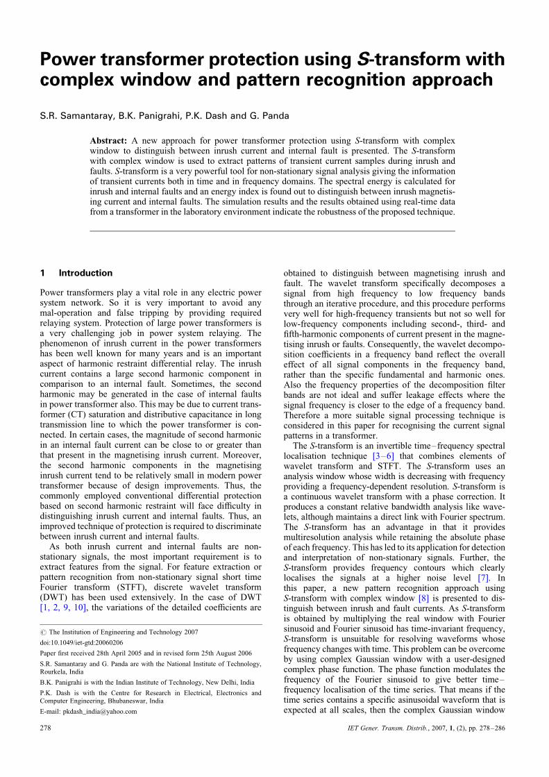
3 System studied
The simulation study has been done on the system compris-ing a 2000 MVA generator and 1000 MVA with 500 kV/220 kV transformer shown in Fig. 1. The generator X/Rratio is 10. The primary winding voltage, R (pu) and L(pu) are 500 kV, 0.003 and 0.09, respectively, and secondarywinding voltage, R (pu) and L (pu) are 220 kV, 0.003 and0.09, respectively. Also simulation tests are done on100 MVA capacity transformer with other parametersremaining the same. The winding configuration such asY-Y, Y-D, D-Y and D-D are taken into considerationfor extensive study. The study has been made for bothinrush current and different internal faults with andwithout load. Faults are created for winding-to-ground,winding-to-winding with and without load. The samplingrate is chosen 1.0 kHz at 50 Hz frequency. A cycle contains20 samples. One cycle data of inrush and fault have beenprocessed through S-transform to give the spectral energyat different contour levels. The simulation model isdeveloped using Matlab–Simulink software modules. Forstudying the performance of the proposed approach undernoisy conditions, random noise with SNR up to 20 dB hasbeen added to the differential current signal. The loadtaken here is 100 MW and 80 MVAR.
Also real-time tests (experimental) have been conductedfor a single-phase transformer of 5 kVA capacity with400 V/230 V in the laboratory. The winding configurationis Y–Y for the experimental set-up. The inrush currentand internal faults like winding-to-winding and winding-to-ground for different turn positions are measured by using apower scope.
4 Results and discussion
4.1 Differential protection based on secondharmonic restraint
The differential protection based on second harmonicrestraint using adaptive linear combiner (ADALINE) [13]is tested. The results of differential protection based onsecond harmonic restraint are given in Fig. 2. A factor of6 is multiplied to the actual amplitude of the second harmo-nic component present in the current waveform to producethe restraint signal. The operating signal is the magnitude ofthe fundamental component. As seen from the Fig. 2a, thetripping signal for inrush and fault based on second harmo-nic restraint using ADALINE are well separated and athreshold can be set for the tripping signal above whichrelay restrains (inrush) and below which relay operates(fault). This is possible when the second harmonic magni-tude compared with fundamental exceeds 20% and thefault current has a lower second harmonic component com-pared with the fundamental component. But when thesecond harmonic component is nearly 10% in both the
Generator Transformer
Load
Switch
Relay
Fig. 1 System model
280
cases, the tripping signal for internal fault and inrushcurrent overlap each other and no threshold can be set forthe tripping signal as shown in Fig. 2b. Thus, the secondharmonic restraint fails in such cases having low secondharmonic component compared with the fundamental.
The above problem is solved by the proposed method,which discriminates the inrush current and internal faulteven if the second harmonic component is same in bothinrush and internal fault with the existing operating con-ditions and configurations. In this case, the proposedenergy index is 2.57 for inrush current and 3.89 for internalfaults, which are well separated with the set threshold. Thegenerated S-contours for inrush and internal faults are givenin Figs. 2c and d, respectively. The S-contours with contourlevel 1 for inrush and internal fault are given in Figs. 2eand f, respectively. The above study is made on synthesisingthe inrush and fault current and processing the respectivesignals through ADALINE and S-transform. After confirm-ing the results on synthesised data, the correspondingsignals for simulation models and experimental set-up aretested and the results are given in the following sections.
4.2 Feature extraction using S-transform
Data for inrush current and internal faults are generated fromthe simulation model given in Fig. 1. The S-transform of thecorresponding data is computed. The frequency contours(S-contours) and the spectral energy (energy) of S-transformof inrush current and fault signals are calculated for onecycle data from the inception of inrush and fault conditions.The frequency contours (levels 1–9) are shown inFigs. 3a–h with frequency. But the frequency contours forcontour level 1 is obtained as shown in Figs. 4a–h for simu-lation data. It is clear from the frequency contour (S-contour)with contour levels 1–9 that in case of inrush current, the con-tours are present only during positive peaks of the currentwaveform compared with various fault conditions. Forfaults occurring on the transformer, the frequency contoursare found with positive and negative sections of the faultcurrent waveform. However, S-transform output contourlevel 1 for inrush current shows that the frequency contouris concentric around second harmonic frequency, and in thecase of faults, the frequency contours are around fundamentalfrequency. Similarly, the data retrieved from real-time trans-former tests in the laboratory are processed throughS-transform to yield the frequency contours for both inrushcurrent and internal faults. The frequency contours for real-time generated data are as shown in Figs. 5a–c withcontour levels 1–9. Figs. 6a–c depict frequency contours atcontour level 1 only for real-time data. From the figures, itis clearly seen that the inrush current having different fre-quency contours exhibits interrupted patterns in comparisonto internal fault current showing regular patterns.
Tables 1 and 2 depict the spectral energy content of inrushcurrent and internal faults for various conditions. It is clearlyseen that the spectral energy content of inrush currents aremuch less when compared with the spectral energy contentof internal faults for S-contours with contour levels 1–9.But the spectral energy content of inrush current is morethan that of internal faults for S-contours with contourlevel-1 only. The energy calculations lead to the energyindex which discriminates inrush current from internal faults.
4.3 Energy index to distinguish inrush currentfrom faults
From the above results, energy index is found out to dis-tinguish inrush current from internal faults. The energy
IET Gener. Transm. Distrib., Vol. 1, No. 2, March 2007

Fig. 2 Results of differential protection based on the second harmonic restraint and proposed S-transform based technique for synthesised data
a Tripping signals obtained form ADALINE when the second harmonic component is 60 and 10% in inrush current and fault, respectivelyb Tripping signals obtained form ADALINE when the second harmonic component is 10% in both inrush current and fault, respectivelyc S-contours for inrush currentd S-contours for internal faulte S-contours for inrush current at contour level 1f S-contours for internal fault at contour level 1
281
index is given as
Energy index ¼
Energy of S-contours
with contour level-1 to contour level-9
Energy of S-contours with contour level-1
ð15Þ
IET Gener. Transm. Distrib., Vol. 1, No. 2, March 2007
The devised index has been derived from the ratio of energyof S-contours from levels 1–9 to energy of S-contours atlevel 1, which clearly indicates that the ratio of energycontent of all harmonic components to the energy of thefundamental or second harmonic depends on the kind ofevents under analysis, inrush or fault. The energy index is1.09 (minimum) and 1.22 (maximum) for inrush current

Fig. 3 Frequency contours for simulation data
a S-contours for inrush current of a-phaseb S-contours for inrush current of b-phasec S-contours for inrush current of c-phased S-contours for inrush current of a-phase with SNR 20 dBe S-contours for winding to ground fault of a-phasef S-contours for winding to ground fault of c-phase with SNR 20 dBg S-contours for winding to ground fault of b-phase with loadh S-contours for winding to winding fault of a-c with load (a-phase)
IET Gener. Transm. Distrib., Vol. 1, No. 2, March 2007282

Fig. 4 Frequency contours for simulation data at contour level-1 only
a S-contours for inrush current of a-phase at contour level 1b S-contours for inrush current of b-phase at contour level 1c S-contours for a-phase winding–winding fault (a-b fault) at contour level 1d S-contours for b-phase winding–winding–ground fault (bc-g fault) at contour level-1with SNR 20 dBe S-contours for b-phase winding–winding fault (b-c fault) at contour level 1f S-contours for inrush current of b-phase (b-c fault) at contour level 1 with SNR 20 dBg S-contours for inrush current of c-phase (bc-g fault) at contour level 1h S-contours for inrush current of c-phase (bc-g fault) at contour level 1 with SNR 20 dB
IET Gener. Transm. Distrib., Vol. 1, No. 2, March 2007 283

and 4.01 (minimum) and 5.48 (maximum) for internal faultsfor signals without noise. Also the energy index for signalswith noise gives the similar result, which clearly distin-guishes inrush from faults. Table 1 depicts the energyindex for simulation test with 1000 MVA capacity andTable 2 provides the energy index for simulation test with100 MVA capacity transformers. The energy index for theexperimental set-up is given in Table. 3. For experimentaldata, the energy index is above 1.65 for inrush current and9.66 (maximum) and 6.07 (minimum) for internal faults,which clearly distinguishes faults from inrush condition.
To distinguish the inrush from internal faults, a suitablethreshold value of 3.0 is set for energy index, belowwhich it is inrush current and above which internal fault.The threshold value is chosen after testing the modelunder different operating conditions and capacities of the
Fig. 5 Frequency contours for real-time data
a S-contours for inrush current (experimental data)b S-contours for 86–0% turn-to-turn fault (experimental data)c S-contours for 50–0% turn to turn faults (experimental data)
284
transformer. The tests have been done for 100 MVA and1000 MVA transformers with different configuration suchas Y-Y, Y-D, D-Y and D-D. It is found that the energyindex is below 1.03 for inrush current and above 3.51 forinternal faults taking both results into consideration forsimulation study when the second harmonic magnitudecompared with fundamental exceeds 20% and the faultcurrent has a lower second harmonic component comparedwith the fundamental component.
As seen in Table 1, the proposed technique also workssuccessfully where the second harmonic component issame (10–15%) in both inrush and internal faults. Theenergy index for 1000 MVA transformer is below 2.45and above 3.24 for inrush and internal fault, respectively.Similarly, the energy indices for inrush and internal faultare 2.52 and 3.24, respectively, with SNR 20 dB. Also,
Fig. 6 Frequency contours for real-time data at contour level-1only
a S-contours for inrush current at contour level 1 (experimental data)b S-contours for inrush current at contour level 1 for 50-0 fault(experimental data)c S-contours for inrush current at contour level 1 for 50-86 fault(experimental data)
IET Gener. Transm. Distrib., Vol. 1, No. 2, March 2007

Table 1: Energy and energy index for inrush and fault conditions for simulation data (1000 MVA transformers)
Events (simulation data) Energy (at
contour
level 1)
Energy (for
contour
levels 1–9)
Energy
index
Energy (at
contour level 1)
(SNR 20 dB)
Energy (for
contour levels 1–9
with SNR 20 dB)
Energy index
(SNR 20 dB)
Inrush-a (Y-Y) 38.02 45.02 1.18 41.06 56.35 1.37
Inrush-b (Y-D) 32.64 35.64 1.09 39.64 45.23 1.14
Inrush-c (Y-Y) 36.78 40.12 1.09 34.65 42.65 1.23
Inrush-a (loaded) (D-D) 35.62 43.65 1.22 39.82 47.69 1.19
Inrush-b (loaded) (Y-Y) 29.64 33.54 1.13 35.48 39.48 1.11
Inrush-c (loaded) (Y-D) 32.87 36.98 1.12 32.98 37.45 1.13
a-g fault (Y-Y) 24.35 119.63 4.91 24.46 120.53 4.92
b-g fault (Y-D) 25.24 110.02 4.35 26.41 113.05 4.28
c-g fault (Y-Y) 24.15 114.32 4.73 24.58 104.03 4.23
a-b fault (a-phase) (D-Y) 21.97 120.53 5.48 22.23 153.06 6.88
a-b fault (b-phase) (D-D) 22.35 112.56 5.03 23.34 113.62 4.86
ca-g fault (a-phase) (D-Y) 24.52 115.64 4.71 24.76 110.25 4.45
ca-g fault (c-phase) (Y-Y) 21.26 120.65 5.67 21.34 114.68 5.37
bc-g fault (b-phase) (D-Y) 25.64 102.83 4.01 24.68 108.03 4.37
bc-g fault (c-phase) (D-D) 26.35 112.46 4.26 26.58 93.52 3.51
Inrush and fault both contain 10–15% second harmonic
Inrush-a (Y-Y) 29.36 62.34 2.12 31.25 67.85 2.17
Inrush-b (Y-D) 31.26 60.57 1.93 32.65 61.58 1.88
Inrush-c (Y-Y) 29.64 72.68 2.45 30.68 77.59 2.52
a-b fault (a-phase) (D-Y) 25.63 88.96 3.47 26.31 94.85 3.60
a-b fault (b-phase) (D-D) 23.87 98.678 4.13 24.68 100.26 4.06
ca-g fault (a-phase) (D-Y) 22.68 73.68 3.24 23.68 76.84 3.24
ca-g fault (c-phase) (Y-Y) 21.48 82.68 3.84 22.64 86.35 3.81
Table 2: Energy and energy index for inrush and fault conditions for simulation data (100 MVA transformers)
Events (simulation data) Energy (at
contour
level 1)
Energy (for
contour
levels 1–9)
Energy
index
Energy (at
contour level 1)
(SNR 20 dB)
Energy (for
contour level 1–9
with SNR 20 dB)
Energy index
(SNR 20 dB)
Inrush-a (Y-Y) 36.25 41.65 1.14 38.91 55.12 1.41
Inrush-b (Y-D) 30.26 32.65 1.07 36.54 40.65 1.11
Inrush-c (Y-Y) 34.65 39.48 1.13 31.56 39.84 1.26
Inrush-a (loaded) (D-D) 32.65 40.21 1.23 36.58 42.78 1.16
Inrush-b (loaded) (Y-Y) 30.65 31.65 1.03 35.48 37.68 1.06
Inrush-c (loaded) (Y-D) 29.87 35.14 1.17 29.47 33.45 1.13
a-g fault (Y-Y) 22.65 111.65 4.92 22.64 112.65 4.97
b-g fault (Y-D) 21.65 120.65 5.57 23.54 111.62 4.74
c-g fault (Y-Y) 22.87 124.36 5.43 21.87 100.87 4.61
a-b fault (a-phase) (D-Y) 19.68 125.64 6.38 19.38 146.87 7.57
a-b fault (b-phase) (D-D) 20.46 109.64 5.35 21.56 109.84 5.09
ca-g fault (a-phase) (D-Y) 23.64 114.65 4.84 22.35 104.68 4.68
ca-g fault (c-phase) (Y-Y) 20.75 119.78 5.77 20.84 99.64 4.78
bc-g fault (b-phase) (D-Y) 22.65 120.65 5.32 23.48 102.47 4.36
bc-g fault (c-phase) (D-D) 23.48 118.65 5.05 25.57 101.58 3.97
Inrush and fault both contain 10–15% second harmonic
Inrush-a (Y-Y) 29.68 66.54 2.24 31.25 66.54 2.12
Inrush-b (Y-D) 28.69 55.98 1.95 29.68 62.65 2.11
Inrush-c (Y-Y) 26.87 58.95 2.19 28.65 59.68 2.08
a-b fault (a-phase) (D-Y) 22.35 94.65 4.23 21.65 82.57 3.81
a-b fault (b-phase) (D-D) 24.68 88.21 3.57 25.14 81.69 3.24
ca-g fault (a-phase) (D-Y) 25.44 94.65 3.72 26.54 95.87 3.61
ca-g fault (c-phase) (Y-Y) 24.99 82.45 3.29 26.54 100.23 3.77
IET Gener. Transm. Distrib., Vol. 1, No. 2, March 2007 285

similar observations are made in Table 2 for 100 MVAtransformers, where the energy index is below 2.24 andabove 3.29 for inrush and internal fault, respectively.Similarly, the energy index is below 2.12 and above 3.24for inrush and internal fault, respectively, with SNR20 dB. The results for above cases are depicted inTables 1 and 2 in bold and italics. The energy index is
Table 3: Energy and energy index for inrush and faultconditions for experimental data
Events
(experimental
data)
Energy
(at contour
level 1)
Energy
(for contour
levels 1–9)
Energy
index
Inrush (Y-Y) 91.56 142.65 1.55
Inrush (loaded)(Y-Y) 80.67 133.65 1.65
50-0 fault (Y-Y) 42.32 256.98 6.07
50-g fault (Y-Y) 33.68 325.64 9.66
86-0 fault (Y-Y) 46.87 314.85 6.71
86-g fault (Y-Y) 34.56 241.85 6.99
50-86 fault (Y-Y) 44.12 310.65 7.04
86-100 fault (Y-Y) 55.98 371.89 6.64
50-100 fault (Y-Y) 52.41 342.98 6.54
Fig. 7 Flow chart to distinguish inrush current from internalfaults
286
1.65 for inrush and 6.07 for internal fault for experimentaltest as given in Table 3. Thus, from the above results, it isseen that the proposed technique works successfullywhere the second harmonic restraint fails. The flow chartto distinguish inrush current from fault is given in Fig. 7.In the proposed method, the energy content of S-transformof one cycle current signal is taken for calculation. Theone cycle data takes 20 ms and time taken for S-transformand the algorithm is nearly 10 ms. Thus, the total timetaken by the proposed protection scheme is 30 ms approxi-mately from the inception of fault.
5 Conclusions
This paper presents a new approach for discriminationbetween inrush current and internal faults in powertransformer by pattern recognition technique usingS-transform. S-transform is found to be very powerful toolfor non-stationary signal analysis and gives the frequencycontours for inrush current and internal faults very distinctlyas shown in the figures where second harmonic is pronouncedin the case of inrush current compared with faults. The spec-tral energy is computed for inrush current and internal faultsat different contour levels. The energy index is calculated todistinguish inrush current and internal faults. Also, the resultsunder noisy conditions provide significant distinctionsbetween faults and inrush. The proposed technique is com-pared with the existing differential protection based onsecond harmonic restraint and found successful comparedto the later. Also the proposed one is very robust asS-transform is very less prone to noise compared withwavelet transform and so the application can be extendedfor protection schemes for large power transformers.
6 References
1 Hon, S.N., and Qin, W.: ‘A wavelet based method to discriminatebetween inrush and internal faults’. IEEE, 2000, pp. 927–931
2 Youssef, O.A.S.: ‘Discrimination between faults and magnetizinginrush currents in transformers based on wavelet transforms’, Electr.Power Syst. Res., 2002, 63, pp. 87–94
3 Pinnegar, C.R., and Mansinha, L.: ‘Time local Fourier analysis with ascalable, phase modulated analyzing function: the S-transform with acomplex window’, Signal Process., 2004, 84, pp. 1167–1176
4 Pinnegar, C.R., and Mansinha, L.: ‘The S-transform with windows ofarbitrary and varying window’, Geophysics, 2003, 68, pp. 381–385
5 Mansinha, L., Stockwell, R.G., and Lowe, R.P.: ‘Pattern analysis withtwo dimensional spectral localization: application of two-dimensionalS-transforms’, Physica A, 1997, 239, pp. 286–295
6 Liavanos, G., Ranganathan, N., and Jiang, J.: ‘Heart sound analysisusing the S-transform’, IEEE Comp. Cardiol., 2000, 27, pp. 587–590
7 Dash, P.K., Panigrahi, B.K., and Panda, G.: ‘Power quality analysisusing S-transform’, IEEE Trans. Power Deliv., 2003, 18, (2),pp. 406–411
8 Stockwell, R.G., Mansinha, L., and Lowe, R.P.: ‘Localization of thecomplex spectrum: the S-transform’, IEEE Trans. Signal Process.,1996, 44, pp. 998–1001
9 Mao, P.L., and Aggarwal, R.K.: ‘A novel approach to theclassification of the transient phenomena in power transformersusing combined wavelet transform and neural network’, IEEETrans. Power Deliv., 2001, 16, (4), pp. 654–660
10 Jiang, F., Bo, Z.Q., Chin, P.S.M., Redfern, M.A., and Chen, Z.:‘Power transformer protection based on transient detection usingdiscrete wavelet transform (DWT)’. IEEE, 2000
11 Phadke, A.G., and Thorp, J.S.: ‘Computer relay for power system’(Research Studies Press Ltd., 1998)
12 Perez, L.G., Flechsig, A.J., Meador, J.L., and Obradovic, Z.: ‘Trainingan artificial neural network to discriminate between magnetizinginrush and internal faults’, IEEE Trans. Power Deliv., 1994, 9, (1),pp. 434–441
13 Dash, P.K., Swain, D.P., Liew, A.C., and Rahman, S.: ‘An adaptivelinear combiner for on-line tracking of power system harmonics’,IEEE Trans Power Syst., 1996, 11, (4), pp. 1730–1735
IET Gener. Transm. Distrib., Vol. 1, No. 2, March 2007