Embed Size (px)
Citation preview
ESPOO 2006 VTT WORKING PAPERS 45
Preliminary Study of Modelling Dynamic Properties of
Magnetorheological Fluid Damper
Jaakko Heinonen
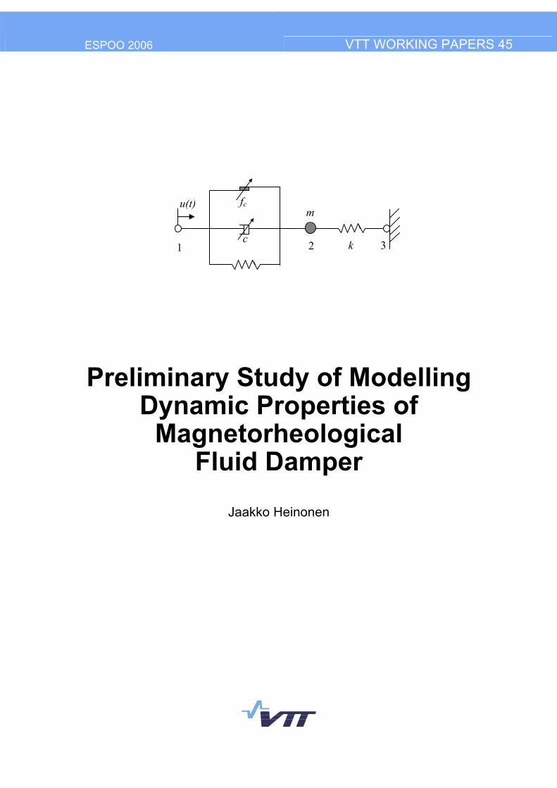
u(t)
c 1 2 k 3
m fc
ISBN 951�38�6597�5 (URL: http://www.vtt.fi/inf/pdf/) ISSN 1459�7683 (URL: http://www.vtt.fi/inf/pdf/) Copyright © VTT 2006
JULKAISIJA � UTGIVARE � PUBLISHER
VTT, Vuorimiehentie 5, PL 2000, 02044 VTT puh. vaihde 020 722 111, faksi 020 722 4374
VTT, Bergsmansvägen 5, PB 2000, 02044 VTT tel. växel 020 722 111, fax 020 722 4374
VTT Technical Research Centre of Finland, Vuorimiehentie 5, P.O.Box 2000, FI�02044 VTT, Finland phone internat. +358 20 722 111, fax +358 20 722 4374
VTT, Kemistintie 3, PL 1000, 02044 VTT puh. vaihde 020 722 111, faksi 020 722 7007
VTT, Kemistvägen 3, PB 1000, 02044 VTT tel. växel 020 722 111, fax 020 722 7007
VTT Technical Research Centre of Finland, Kemistintie 3, P.O. Box 1000, FI-02044 VTT, Finland phone internat. +358 20 722 111, fax +358 20 722 7007
Technical editing Maini Manninen
3
Published by
Series title, number and report code of publication
VTT Working Papers 45 VTT�WORK�45
Author(s) Heinonen, Jaakko Title Preliminary Study of Modelling Dynamic Properties of Magnetorheological Fluid Damper
Abstract A preliminary study was conducted to investigate numerical models that can be used to simulate the dynamic behaviour of a damper based on magnetorheological (MR) materials. Several articles presenting the results of experimental testing and mathematical modelling have been published recently. The goal for this study was to implement a selected model into the finite element method (FEM) for structural dynamic analysis purposes in the time domain. A simplified controllable spring-dashpot-friction element was implemented as a user element subroutine ("smart connector element") into the ABAQUS/Standard FEM-program. The model was verified by numerical comparisons. It was observed that the smart connector element can be applied to simulate a similar dynamic response to that measured in the experiments. Therefore, it can be employed to analyze adaptive structures in which the MR-damper is utilized to control dynamic properties. Keywords magnetorheological materials, MR materials, smart structures, vibration isolation, vibration control, FEM
ISBN 951�38�6597�5 (URL: http://www.vtt.fi/inf/pdf/)
Series title and ISSN Project number VTT Working Papers 1459�7683 (URL: http://www.vtt.fi/inf/pdf/)
Date Language Pages March 2006 English 36 p.
Name of project Commissioned by SULAWIND VTT Technical Research Centre of Finland
Contact Publisher VTT Technical Research Centre of Finland P.O. Box 1000, FI-02044 VTT, Finland Phone internat. +358 20 722 111 Fax +358 20 722 7007
VTT Information Service P.O. Box 2000, FI�02044 VTT, Finland Phone internat. +358 20 722 4404 Fax +358 20 722 4374
4
Preface This paper presents available models for magnetorheological (MR) materials and dampers that can be applied in structural analysis. The work was carried out in VTT´s technology theme: Intelligent Products and Systems under the topic Embedded Structural Intelligence. The objective in this topic is to cost-efficiently embed intelligence into structures, which can enable utilisation of entirely new types of product concepts with high performance and reliable operation. The key focus area is to develop functional materials, affordable wireless measurement technology and control, which are adaptable to operating conditions, and to apply these in vibration, durability and shape control.
The author would like to acknowledge Dr. Tuomo Kärnä for his support and guidance during this study and senior research scientist Ilkka Hakola for the review.
5
Contents
Preface ...............................................................................................................................4
1. Introduction..................................................................................................................6
2. Material behaviour .......................................................................................................7 2.1 General ...............................................................................................................7 2.2 MR-damper ........................................................................................................7 2.3 MR-fluid properties ............................................................................................9 2.4 Operation modes...............................................................................................10 2.5 Experiments and phenomenological models ....................................................11
2.5.1 Bingham�s model .................................................................................11 2.5.2 Bouc-Wen model .................................................................................11 2.5.3 Li�s model ............................................................................................12 2.5.4 Oh and Onoda model ...........................................................................15 2.5.5 Choi�s model ........................................................................................17
3. Numerical simulations ...............................................................................................19 3.1 Dynamic analysis .............................................................................................19
3.1.1 General .................................................................................................19 3.1.2 Equivalent model for FEM...................................................................19 3.1.3 Results ..................................................................................................22
3.2 Quasi-static analysis .........................................................................................23 3.2.1 General .................................................................................................23 3.2.2 Effect of force components ..................................................................24 3.2.3 Testing with artificial parameters.........................................................28 3.2.4 Dissipation energy................................................................................30 3.2.5 Model verification................................................................................32
4. Conclusions................................................................................................................34
References .......................................................................................................................35
6
1. Introduction Vibration isolators or dampers are commonly used to mitigate vibrations in structures or machines. The isolators are typically passive and they are designed to reduce the vibration of the most undesired frequency. However, in many applications, the excitation frequency varies across a large range. In a semi-active device, the stiffness or damping can be adjusted during operation. Changing the stiffness of the support device can be exploited by moving the eigenfrequency of the system to bypass the resonance. Reliable control of the support device requires monitoring of a critical point of structure and knowledge about the frequency response of the system. This kind of adaptive isolator can change operation conditions according to dominant loading resulting in improved vibration isolation capability compared to passive systems. Undesired vibrations are reduced in different loading conditions, i.e. a large frequency range is covered.
Several concepts have been studied recently to utilize smart materials in adaptive structures. Magnetorheological (MR) fluids and elastomers, shape memory alloys (SMA) and piezoelectric materials comprise a class of smart materials whose properties can be controlled. The constitutive behaviour of smart materials couples their mechanical response (stress and strain) with other physical fields like magnetic or electric field or heat, which makes it possible to develop an adaptive structure without complicated mechanisms.
Magnetorheological materials (MR) are a class of materials whose rheological properties are rapidly varied by applying a magnetic field. This change is in proportion to the magnetic field applied and is immediately reversible. MR-materials exhibit rapid, tuneable and reversible transition from a free-flowing state to a semi-solid state upon the application of an external magnetic field. MR-material provides simple, quiet and rapid-response interface between the electronic control and mechanical system to mitigate the vibration of the host structure (Li et al., 2000). MR-materials are useful in many applications because the change in their material properties is large.
A preliminary study was conducted to investigate numerical models that can be used to simulate the dynamic behaviour of a damper based on MR-materials. Several articles presenting the results of experimental testing and mathematical modelling have been published recently. The goal was to implement a selected model into the finite element method (FEM) for structural dynamic analysis purposes in the time domain. ABAQUS/Standard software was used for the numerical simulation in which a controllable MR-damper was introduced as a User Element Subroutine (UEL).
7
2. Material behaviour
2.1 General
MR-materials usually consist of micron-sized (3�8 µm) magnetizeable particles suspended in a liquid. A typical MR-fluid consists of 20�40% by volume of relatively pure iron particles suspended in a carrier liquid such as mineral oil, synthetic oil, water, or glycol. A variety of proprietary additives similar to those found in commercial lubricants are used to discourage gravitational settling and promote particle suspension, enhance lubricity, change initial viscosity, and inhibit wear (Encyclopedia of Smart Materials). A critical particle volume concentration (CPVC) defined by Lokander and Stenberg (2003) depends on the apparent density of powder containing the iron particles. The MR-effect does not increase much with increasing particle content above the CPVC.
2.2 MR-damper
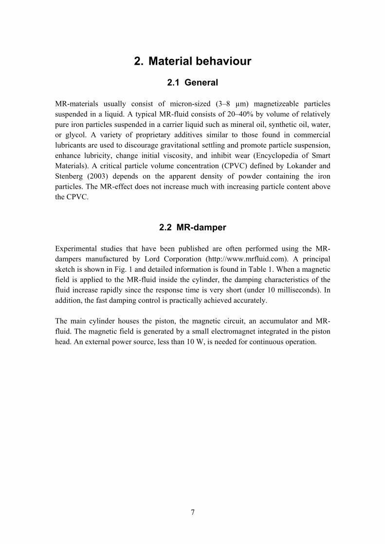
Experimental studies that have been published are often performed using the MR-dampers manufactured by Lord Corporation (http://www.mrfluid.com). A principal sketch is shown in Fig. 1 and detailed information is found in Table 1. When a magnetic field is applied to the MR-fluid inside the cylinder, the damping characteristics of the fluid increase rapidly since the response time is very short (under 10 milliseconds). In addition, the fast damping control is practically achieved accurately.
The main cylinder houses the piston, the magnetic circuit, an accumulator and MR-fluid. The magnetic field is generated by a small electromagnet integrated in the piston head. An external power source, less than 10 W, is needed for continuous operation.
8
Figure 1. Principal sketch of MR-damper (RD-1005 by Lord Corporation) (Li et al., 2000).
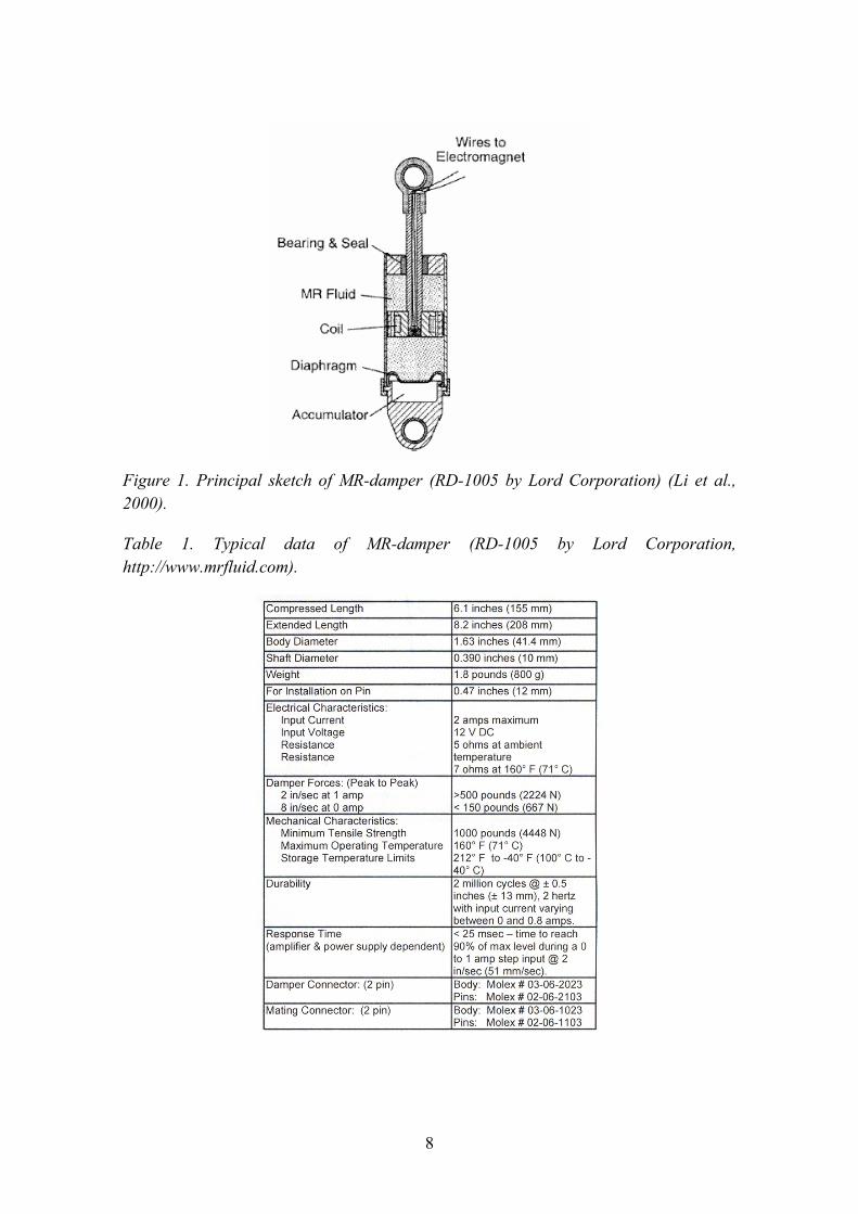
Table 1. Typical data of MR-damper (RD-1005 by Lord Corporation, http://www.mrfluid.com).
9
2.3 MR-fluid properties
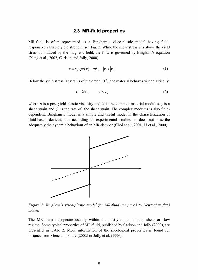
MR-fluid is often represented as a Bingham�s visco-plastic model having field-responsive variable yield strength, see Fig. 2. While the shear stress τ is above the yield stress τy induced by the magnetic field, the flow is governed by Bingham�s equation (Yang et al., 2002, Carlson and Jolly, 2000)
yy ; )sgn( ττγηγττ >+= && (1)
Below the yield stress (at strains of the order 10-3), the material behaves viscoelastically:
y ; ττγτ <=G (2)
where η is a post-yield plastic viscosity and G is the complex material modulus. γ is a shear strain and γ& is the rate of the shear strain. The complex modulus is also field-dependent. Bingham�s model is a simple and useful model in the characterization of fluid-based devices, but according to experimental studies, it does not describe adequately the dynamic behaviour of an MR-damper (Choi et al., 2001, Li et al., 2000).
Figure 2. Bingham�s visco-plastic model for MR-fluid compared to Newtonian fluid model.
The MR-materials operate usually within the post-yield continuous shear or flow regime. Some typical properties of MR-fluid, published by Carlson and Jolly (2000), are presented in Table 2. More information of the rheological properties is found for instance from Genc and Phulé (2002) or Jolly et al. (1996).
10
Table 2. Typical MR-fluid properties (Carlson and Jolly, 2000).
Property Typical value Maximum yield strength, τy 50�100 kPa Maximum field ∼250 kA/m Plastic viscosity η 0.1�1.0 Pa s Operable temperature range -40 to 150 °C (limited by carrier fluid) Contaminants Unaffected by most impurities Response time <milliseconds Density 3�4 g/cm3
2y/τη 10-10 � 10-11 s/Pa
Maximum energy density 0.1 J/cm3 Power supply (typical) 2�25 V @ 1�2 A (2�50 watts)
2.4 Operation modes
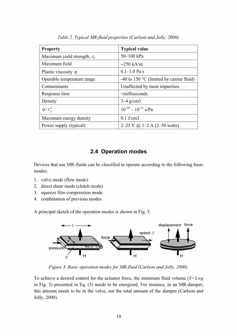
Devices that use MR-fluids can be classified to operate according to the following basic modes:
1. valve mode (flow mode) 2. direct shear mode (clutch mode) 3. squeeze film compression mode 4. combination of previous modes.
A principal sketch of the operation modes is shown in Fig. 3.
Figure 3. Basic operation modes for MR-fluid (Carlson and Jolly, 2000).
To achieve a desired control for the actuator force, the minimum fluid volume (V=Lwg in Fig. 3) presented in Eq. (3) needs to be energized. For instance, in an MR-damper, this amount needs to be in the valve, not the total amount of the damper (Carlson and Jolly, 2000).
11
SFFF
V onoff
on2y
⎟⎟⎠
⎞⎜⎜⎝
⎛⎟⎟⎠
⎞⎜⎜⎝
⎛≥
τηκ
(3)
where κ = 1 for shear mode devices and κ ≈ 2 for flow mode devices. Fon/Foff is a desired control ratio, S is the speed and Fon is the maximum force.
2.5 Experiments and phenomenological models
2.5.1 Bingham�s model
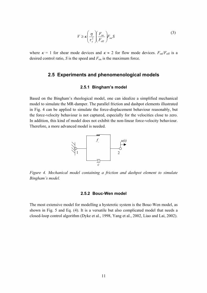
Based on the Bingham�s rheological model, one can idealize a simplified mechanical model to simulate the MR-damper. The parallel friction and dashpot elements illustrated in Fig. 4 can be applied to simulate the force-displacement behaviour reasonably, but the force-velocity behaviour is not captured, especially for the velocities close to zero. In addition, this kind of model does not exhibit the non-linear force-velocity behaviour. Therefore, a more advanced model is needed.
21
u(t)
c
fc
Figure 4. Mechanical model containing a friction and dashpot element to simulate Bingham�s model.
2.5.2 Bouc-Wen model
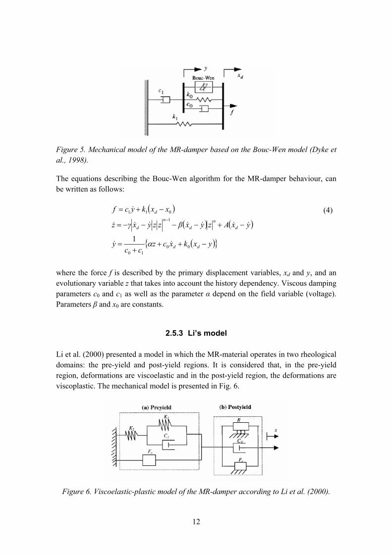
The most extensive model for modelling a hysteretic system is the Bouc-Wen model, as shown in Fig. 5 and Eq. (4). It is a versatile but also complicated model that needs a closed-loop control algorithm (Dyke et al., 1998, Yang et al., 2002, Liao and Lai, 2002).
12
Figure 5. Mechanical model of the MR-damper based on the Bouc-Wen model (Dyke et al., 1998).
The equations describing the Bouc-Wen algorithm for the MR-damper behaviour, can be written as follows:
( )( ) ( )
( ){ }yxkxczcc
y
yxAzyxβzzyxγz
xxkycf
dd
dn
d
n
d
d
−+++
=
−+−−−−=
−+=−
0010
1011
1&&
&&&&&&&
&
α
(4)
where the force f is described by the primary displacement variables, xd and y, and an evolutionary variable z that takes into account the history dependency. Viscous damping parameters c0 and c1 as well as the parameter α depend on the field variable (voltage). Parameters β and x0 are constants.
2.5.3 Li�s model
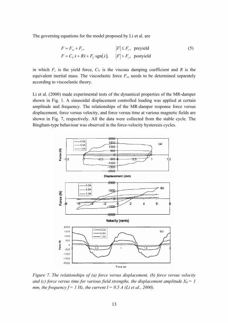
Li et al. (2000) presented a model in which the MR-material operates in two rheological domains: the pre-yield and post-yield regions. It is considered that, in the pre-yield region, deformations are viscoelastic and in the post-yield region, the deformations are viscoplastic. The mechanical model is presented in Fig. 6.
Figure 6. Viscoelastic-plastic model of the MR-damper according to Li et al. (2000).
13
The governing equations for the model proposed by Li et al. are
( ) postyield , ,sgn
preyield , ,
cCV
csve
FFxFxRxCF
FFFFF
>++=
≤+=
&&&&
(5)
in which Fc is the yield force, CV is the viscous damping coefficient and R is the equivalent inertial mass. The viscoelastic force Fve needs to be determined separately according to viscoelastic theory.
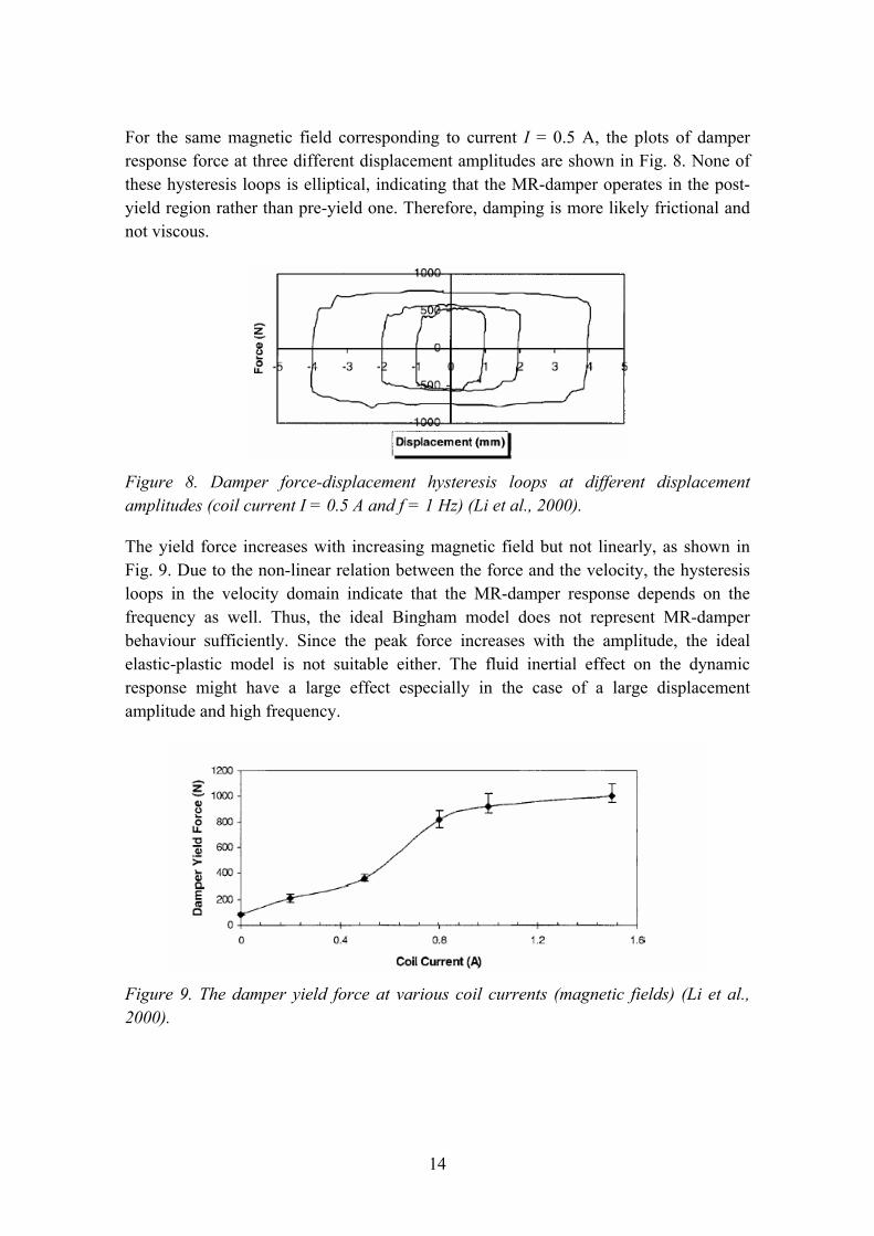
Li et al. (2000) made experimental tests of the dynamical properties of the MR-damper shown in Fig. 1. A sinusoidal displacement controlled loading was applied at certain amplitude and frequency. The relationships of the MR-damper response force versus displacement, force versus velocity, and force versus time at various magnetic fields are shown in Fig. 7, respectively. All the data were collected from the stable cycle. The Bingham-type behaviour was observed in the force-velocity hysteresis cycles.
Figure 7. The relationships of (a) force versus displacement, (b) force versus velocity and (c) force versus time for various field strengths, the displacement amplitude X0 = 1 mm, the frequency f = 1 Hz, the current I = 0.5 A (Li et al., 2000).
14
For the same magnetic field corresponding to current I = 0.5 A, the plots of damper response force at three different displacement amplitudes are shown in Fig. 8. None of these hysteresis loops is elliptical, indicating that the MR-damper operates in the post-yield region rather than pre-yield one. Therefore, damping is more likely frictional and not viscous.
Figure 8. Damper force-displacement hysteresis loops at different displacement amplitudes (coil current I = 0.5 A and f = 1 Hz) (Li et al., 2000).
The yield force increases with increasing magnetic field but not linearly, as shown in Fig. 9. Due to the non-linear relation between the force and the velocity, the hysteresis loops in the velocity domain indicate that the MR-damper response depends on the frequency as well. Thus, the ideal Bingham model does not represent MR-damper behaviour sufficiently. Since the peak force increases with the amplitude, the ideal elastic-plastic model is not suitable either. The fluid inertial effect on the dynamic response might have a large effect especially in the case of a large displacement amplitude and high frequency.
Figure 9. The damper yield force at various coil currents (magnetic fields) (Li et al., 2000).
15
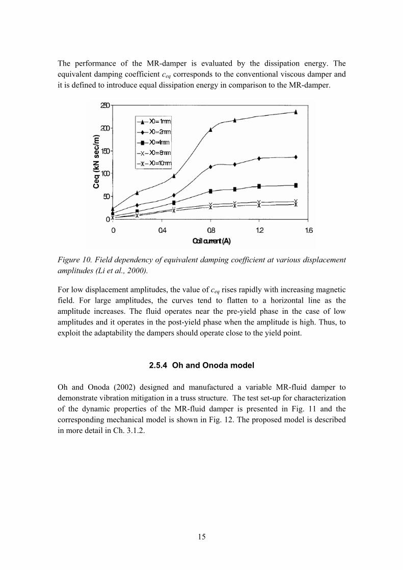
The performance of the MR-damper is evaluated by the dissipation energy. The equivalent damping coefficient ceq corresponds to the conventional viscous damper and it is defined to introduce equal dissipation energy in comparison to the MR-damper.
Figure 10. Field dependency of equivalent damping coefficient at various displacement amplitudes (Li et al., 2000).
For low displacement amplitudes, the value of ceq rises rapidly with increasing magnetic field. For large amplitudes, the curves tend to flatten to a horizontal line as the amplitude increases. The fluid operates near the pre-yield phase in the case of low amplitudes and it operates in the post-yield phase when the amplitude is high. Thus, to exploit the adaptability the dampers should operate close to the yield point.
2.5.4 Oh and Onoda model
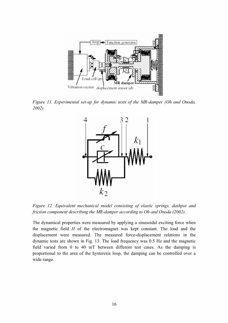
Oh and Onoda (2002) designed and manufactured a variable MR-fluid damper to demonstrate vibration mitigation in a truss structure. The test set-up for characterization of the dynamic properties of the MR-fluid damper is presented in Fig. 11 and the corresponding mechanical model is shown in Fig. 12. The proposed model is described in more detail in Ch. 3.1.2.
16
Figure 11. Experimental set-up for dynamic tests of the MR-damper (Oh and Onoda, 2002).
Figure 12. Equivalent mechanical model consisting of elastic springs, dashpot and friction component describing the MR-damper according to Oh and Onoda (2002).
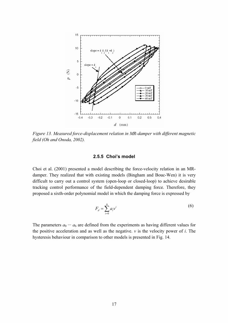
The dynamical properties were measured by applying a sinusoidal exciting force when the magnetic field H of the electromagnet was kept constant. The load and the displacement were measured. The measured force-displacement relations in the dynamic tests are shown in Fig. 13. The load frequency was 0.5 Hz and the magnetic field varied from 0 to 40 mT between different test cases. As the damping is proportional to the area of the hysteresis loop, the damping can be controlled over a wide range.
17
Figure 13. Measured force-displacement relation in MR-damper with different magnetic field (Oh and Onoda, 2002).
2.5.5 Choi�s model
Choi et al. (2001) presented a model describing the force-velocity relation in an MR-damper. They realized that with existing models (Bingham and Bouc-Wen) it is very difficult to carry out a control system (open-loop or closed-loop) to achieve desirable tracking control performance of the field-dependent damping force. Therefore, they proposed a sixth-order polynomial model in which the damping force is expressed by
∑=
=6
0i
iid vaF (6)
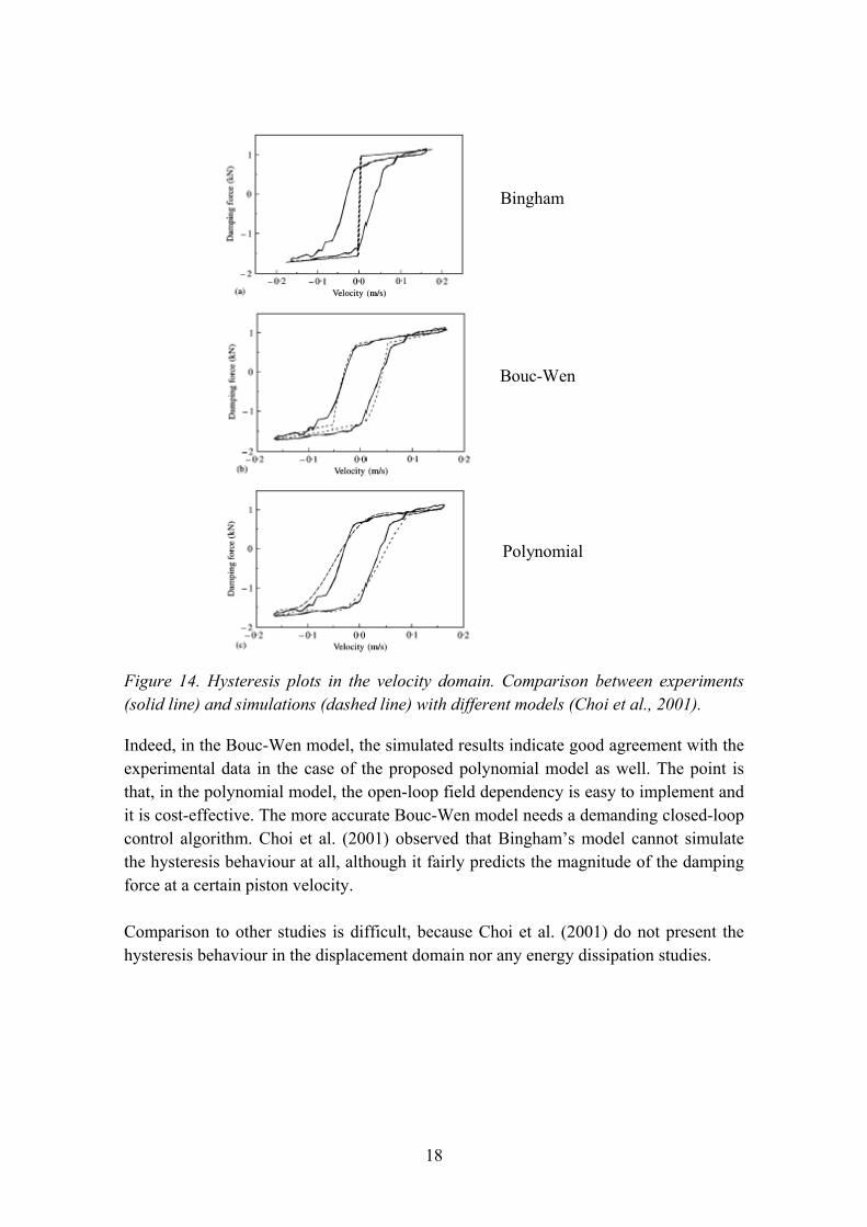
The parameters a0 ··· a6 are defined from the experiments as having different values for the positive acceleration and as well as the negative. v is the velocity power of i. The hysteresis behaviour in comparison to other models is presented in Fig. 14.
18
Bingham
Bouc-Wen
Polynomial
Figure 14. Hysteresis plots in the velocity domain. Comparison between experiments (solid line) and simulations (dashed line) with different models (Choi et al., 2001).
Indeed, in the Bouc-Wen model, the simulated results indicate good agreement with the experimental data in the case of the proposed polynomial model as well. The point is that, in the polynomial model, the open-loop field dependency is easy to implement and it is cost-effective. The more accurate Bouc-Wen model needs a demanding closed-loop control algorithm. Choi et al. (2001) observed that Bingham�s model cannot simulate the hysteresis behaviour at all, although it fairly predicts the magnitude of the damping force at a certain piston velocity.
Comparison to other studies is difficult, because Choi et al. (2001) do not present the hysteresis behaviour in the displacement domain nor any energy dissipation studies.
19
3. Numerical simulations
3.1 Dynamic analysis
3.1.1 General
The goal was to study the feasibility of different models of MR-materials to be implemented into the finite element method (FEM) for structural dynamic analysis purposes in the time domain. ABAQUS/Standard software was used for the numerical simulation. A controllable MR-damper was introduced as a User Element subroutine (UEL). The basis of this routine was developed earlier by the author (Heinonen, 2002). As described in the previous chapters, the Bouc-Wen model is versatile for modelling hysteresis. One disadvantage is that it needs a closed-loop control algorithm and several parameters need to be calibrated. Therefore, in this study, a simpler open-loop model was implemented to simulate the hysteresis behaviour. Both dynamic and quasi-static simulations were carried out. The simulations were based on the model and parameters proposed by Oh and Onoda (2002) and the model verification was based on the experimental test shown in that paper. Verification of the FEM-model was made by comparison to the simpler Matlab routine.
3.1.2 Equivalent model for FEM
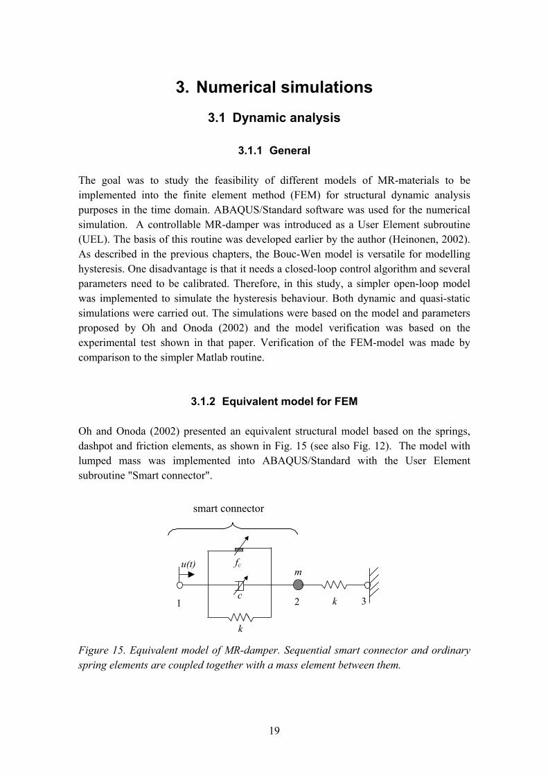
Oh and Onoda (2002) presented an equivalent structural model based on the springs, dashpot and friction elements, as shown in Fig. 15 (see also Fig. 12). The model with lumped mass was implemented into ABAQUS/Standard with the User Element subroutine "Smart connector".
u(t)
k
c1 2 k 3
m fc
smart connector
Figure 15. Equivalent model of MR-damper. Sequential smart connector and ordinary spring elements are coupled together with a mass element between them.
20
The mathematical model of the smart connector, which is a part of the total damper, consists of a spring, a variable viscous damper and a variable friction element. A magnetic field is applied to adjust the viscous and frictional element behaviour. The internal nodal force Fint for the smart connector is defined as follows:
cdsint FFFF ++= (7)
The elastic force Fs for the linear spring with a spring stiffness k is
kuFs = (8)
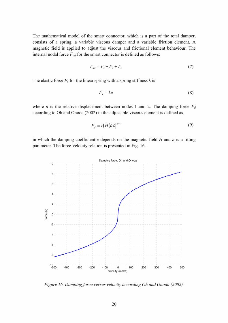
where u is the relative displacement between nodes 1 and 2. The damping force Fd according to Oh and Onoda (2002) in the adjustable viscous element is defined as
( ) 1−= nd uuHcF && (9)
in which the damping coefficient c depends on the magnetic field H and n is a fitting parameter. The force-velocity relation is presented in Fig. 16.
-500 -400 -300 -200 -100 0 100 200 300 400 500-10
-8
-6
-4
-2
0
2
4
6
8
10Damping force, Oh and Onoda
velocity (mm/s)
For
ce (
N)
Figure 16. Damping force versus velocity according Oh and Onoda (2002).
21
Hysteresis caused by the frictional mechanism is described with an incremental solution procedure. The friction force Fc in the adjustable element at time t1 is modelled as follows:
( ) ( )( ) ( ) else ;
; sgn
01
cc
c
scc
fFuHf
uktFtF
<
⎩⎨⎧ ∆+
=&
(10)
in which the ks is a stick stiffness chosen to have a high value ks = 100k and ( ) ( )01 tutuu −=∆ . fc is the threshold value describing the friction force.
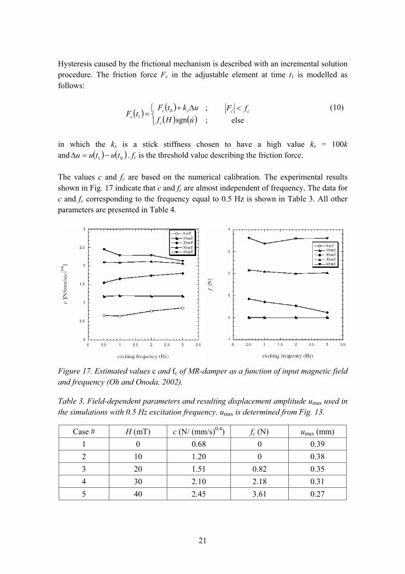
The values c and fc are based on the numerical calibration. The experimental results shown in Fig. 17 indicate that c and fc are almost independent of frequency. The data for c and fc corresponding to the frequency equal to 0.5 Hz is shown in Table 3. All other parameters are presented in Table 4.
Figure 17. Estimated values c and fc of MR-damper as a function of input magnetic field and frequency (Oh and Onoda, 2002).
Table 3. Field-dependent parameters and resulting displacement amplitude umax used in the simulations with 0.5 Hz excitation frequency. umax is determined from Fig. 13.
Case # H (mT) c (N/ (mm/s)0.4) fc (N) umax (mm) 1 0 0.68 0 0.39 2 10 1.20 0 0.38 3 20 1.51 0.82 0.35 4 30 2.10 2.18 0.31 5 40 2.45 3.61 0.27
22
Table 4. Constant parameters used in the simulations (see Fig. 12 for definitions).
k1 (kN/m) k2 (kN/m) m (kg) n 222.2 30.57 50 0.4
3.1.3 Results
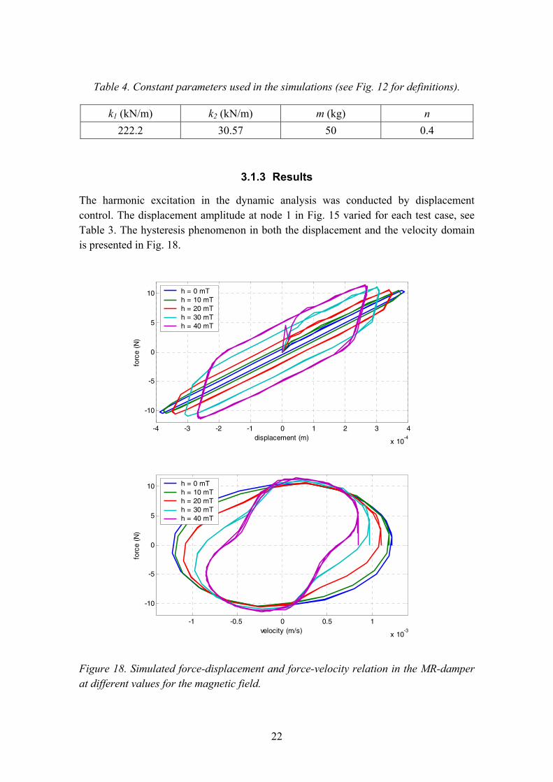
The harmonic excitation in the dynamic analysis was conducted by displacement control. The displacement amplitude at node 1 in Fig. 15 varied for each test case, see Table 3. The hysteresis phenomenon in both the displacement and the velocity domain is presented in Fig. 18.
-4 -3 -2 -1 0 1 2 3 4
x 10-4
-10
-5
0
5
10
displacement (m)
forc
e (N
)
h = 0 mTh = 10 mTh = 20 mTh = 30 mTh = 40 mT
-1 -0.5 0 0.5 1
x 10-3
-10
-5
0
5
10
velocity (m/s)
forc
e (N
)
h = 0 mTh = 10 mTh = 20 mTh = 30 mTh = 40 mT
Figure 18. Simulated force-displacement and force-velocity relation in the MR-damper at different values for the magnetic field.
23
The simulated results in the displacement domain are very similar compared to the experimental results (Figs. 13 and 18). The friction element controls the operation range. With a low or zero friction, the MR-fluid operates mostly at the post-yield range having lower stiffness, and the damping is mainly caused by the fluid resistance. During the reversal, the stiffness is much higher due to frictional behaviour if the frictional force is adjusted at high level by the magnetic field. In this case, the dissipation energy is mainly generated by friction.
Unfortunately, Oh and Onoda (2002) do not present any results in the velocity domain. Therefore, further verification or comparison to other studies cannot be made.
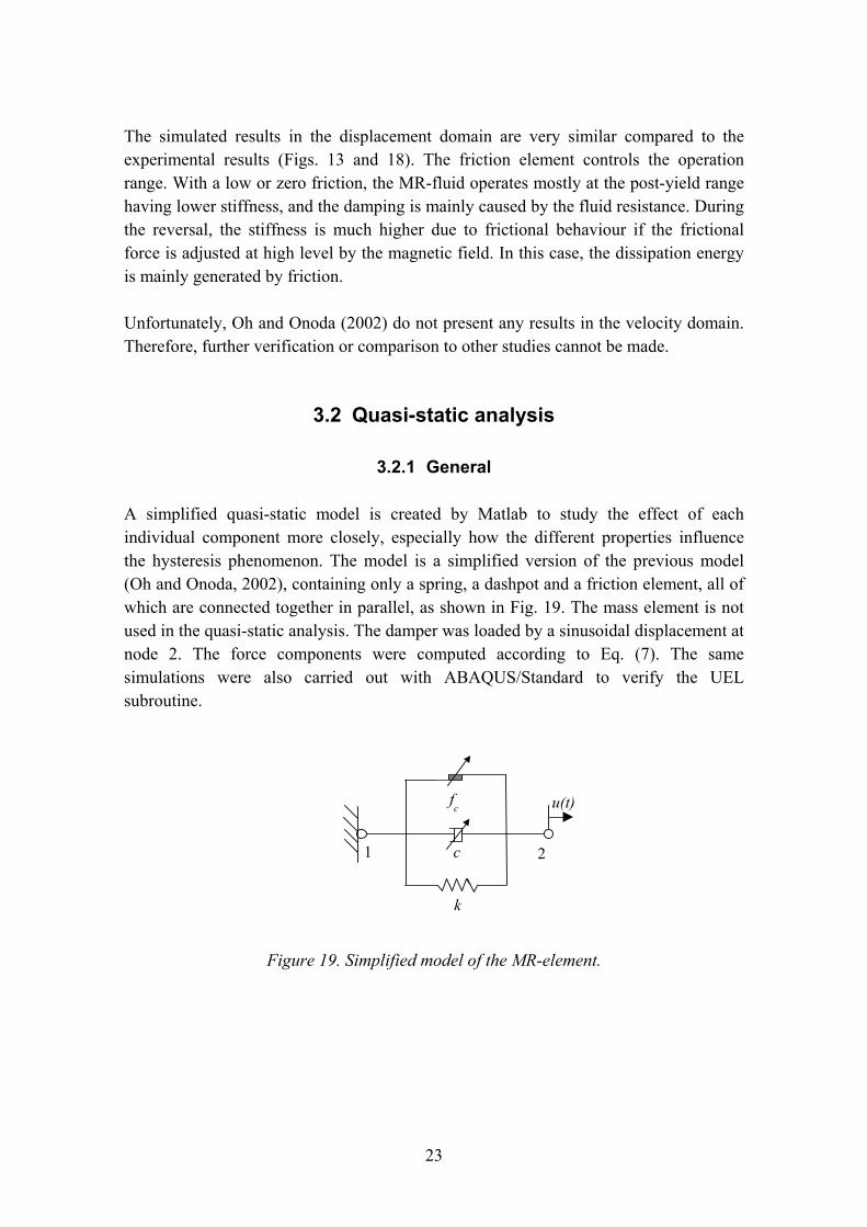
3.2 Quasi-static analysis
3.2.1 General
A simplified quasi-static model is created by Matlab to study the effect of each individual component more closely, especially how the different properties influence the hysteresis phenomenon. The model is a simplified version of the previous model (Oh and Onoda, 2002), containing only a spring, a dashpot and a friction element, all of which are connected together in parallel, as shown in Fig. 19. The mass element is not used in the quasi-static analysis. The damper was loaded by a sinusoidal displacement at node 2. The force components were computed according to Eq. (7). The same simulations were also carried out with ABAQUS/Standard to verify the UEL subroutine.
Figure 19. Simplified model of the MR-element.
21
u(t)
k
c
fc

24
3.2.2 Effect of force components
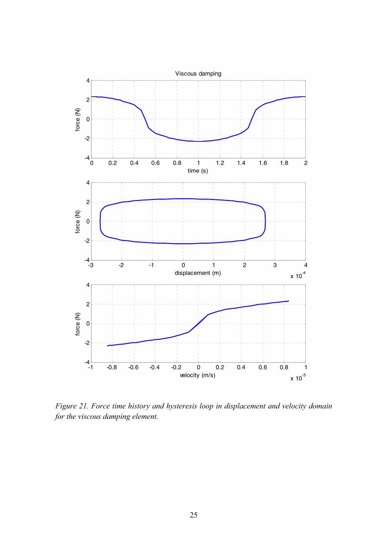
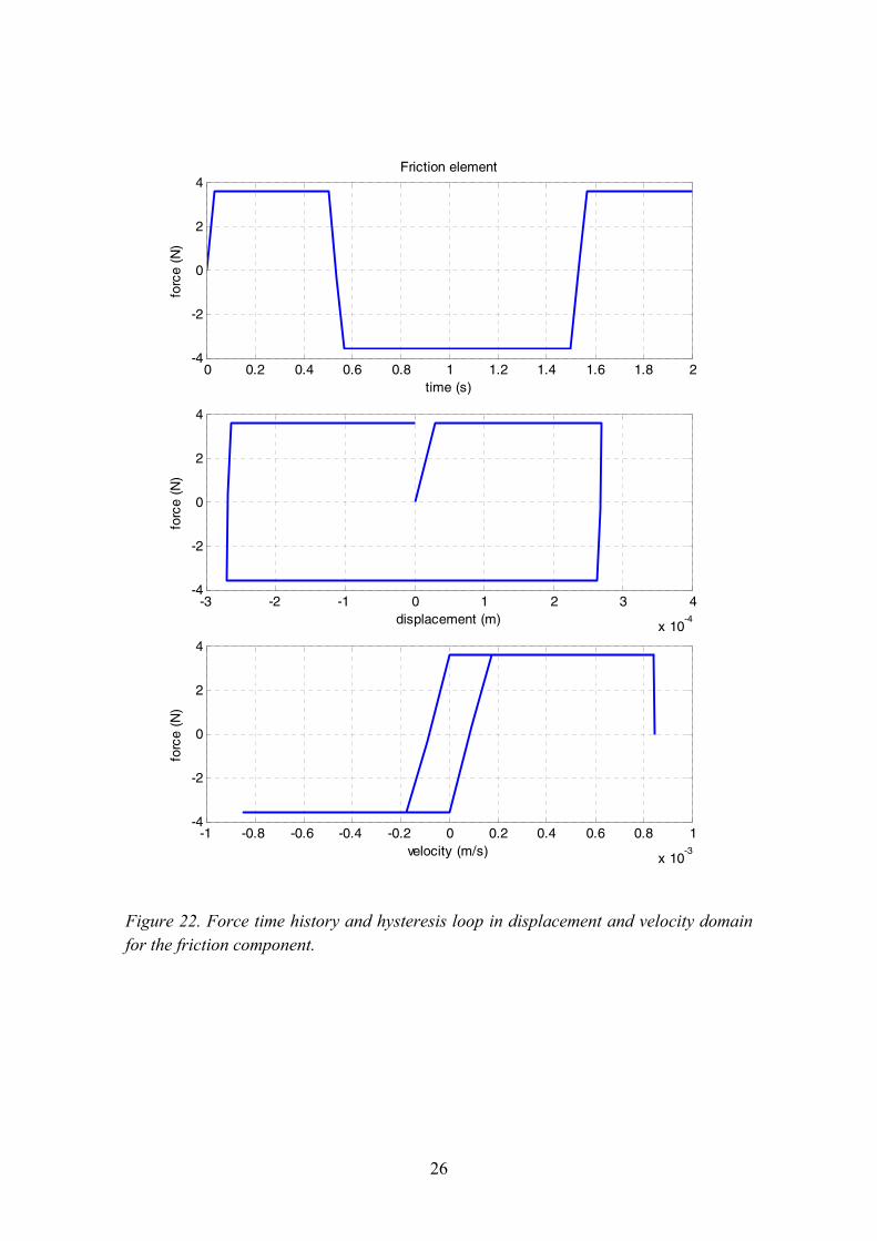
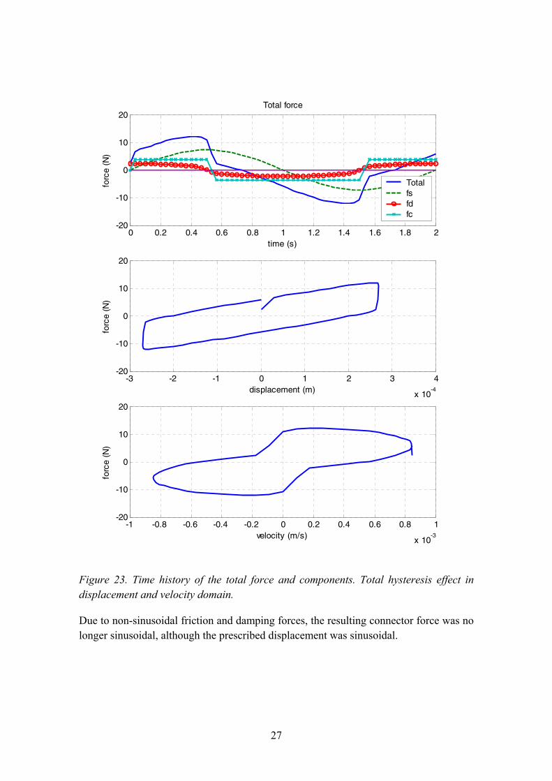
The first Matlab simulation is approximately the same as case #5 in the dynamic FEM-simulations (see Table 3). The serial springs are replaced by one spring with a stiffness coefficient of 26.87 kN/m. The hysteresis phenomenon for each individual force component as well the total effect is characterized in Figs. 20�23.
0 0.2 0.4 0.6 0.8 1 1.2 1.4 1.6 1.8 2-10
-5
0
5
10Elastic spring
time (s)
forc
e (N
)
-3 -2 -1 0 1 2 3 4
x 10-4
-10
-5
0
5
10
displacement (m)
forc
e (N
)
-1 -0.8 -0.6 -0.4 -0.2 0 0.2 0.4 0.6 0.8 1
x 10-3
-10
-5
0
5
10
velocity (m/s)
forc
e (N
)
Figure 20. Force time history and hysteresis loop in displacement and velocity domain for the elastic spring component.
25
0 0.2 0.4 0.6 0.8 1 1.2 1.4 1.6 1.8 2-4
-2
0
2
4Viscous damping
time (s)
forc
e (N
)
-3 -2 -1 0 1 2 3 4
x 10-4
-4
-2
0
2
4
displacement (m)
forc
e (N
)
-1 -0.8 -0.6 -0.4 -0.2 0 0.2 0.4 0.6 0.8 1
x 10-3
-4
-2
0
2
4
velocity (m/s)
forc
e (N
)
Figure 21. Force time history and hysteresis loop in displacement and velocity domain for the viscous damping element.
26
0 0.2 0.4 0.6 0.8 1 1.2 1.4 1.6 1.8 2-4
-2
0
2
4Friction element
time (s)
forc
e (N
)
-3 -2 -1 0 1 2 3 4
x 10-4
-4
-2
0
2
4
displacement (m)
forc
e (N
)
-1 -0.8 -0.6 -0.4 -0.2 0 0.2 0.4 0.6 0.8 1
x 10-3
-4
-2
0
2
4
velocity (m/s)
forc
e (N
)
Figure 22. Force time history and hysteresis loop in displacement and velocity domain for the friction component.
27
0 0.2 0.4 0.6 0.8 1 1.2 1.4 1.6 1.8 2-20
-10
0
10
20Total force
time (s)
forc
e (N
)
Totalfsfdfc
-3 -2 -1 0 1 2 3 4
x 10-4
-20
-10
0
10
20
displacement (m)
forc
e (N
)
-1 -0.8 -0.6 -0.4 -0.2 0 0.2 0.4 0.6 0.8 1
x 10-3
-20
-10
0
10
20
velocity (m/s)
forc
e (N
)
Figure 23. Time history of the total force and components. Total hysteresis effect in displacement and velocity domain.
Due to non-sinusoidal friction and damping forces, the resulting connector force was no longer sinusoidal, although the prescribed displacement was sinusoidal.
28
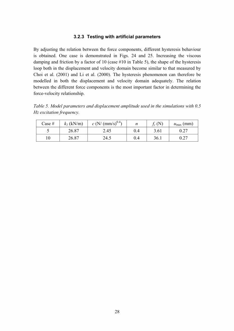
3.2.3 Testing with artificial parameters
By adjusting the relation between the force components, different hysteresis behaviour is obtained. One case is demonstrated in Figs. 24 and 25. Increasing the viscous damping and friction by a factor of 10 (case #10 in Table 5), the shape of the hysteresis loop both in the displacement and velocity domain become similar to that measured by Choi et al. (2001) and Li et al. (2000). The hysteresis phenomenon can therefore be modelled in both the displacement and velocity domain adequately. The relation between the different force components is the most important factor in determining the force-velocity relationship.
Table 5. Model parameters and displacement amplitude used in the simulations with 0.5 Hz excitation frequency.
Case # k1 (kN/m) c (N/ (mm/s)0.4) n fc (N) umax (mm) 5 26.87 2.45 0.4 3.61 0.27 10 26.87 24.5 0.4 36.1 0.27
29
-3 -2 -1 0 1 2 3 4
x 10-4
-80
-60
-40
-20
0
20
40
60
80Hysteresis, Case # 10
displacement (m)
forc
e (N
)
-1 -0.8 -0.6 -0.4 -0.2 0 0.2 0.4 0.6 0.8 1
x 10-3
-80
-60
-40
-20
0
20
40
60
80ks=26870 c0=24.5 k1=2.687e+006 fc1=36.1
velocity (m/s)
forc
e (N
)
Figure 24. Hysteresis loops with increased friction and viscous damping parameters.
30
0 0.2 0.4 0.6 0.8 1 1.2 1.4 1.6 1.8 2-80
-60
-40
-20
0
20
40
60
80Force components, Case # 10
time (s)
forc
e (N
)Totalfsfdf1f2
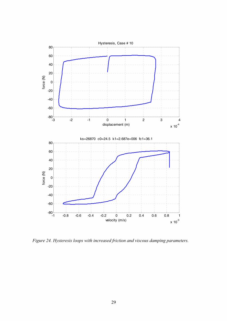
Figure 25. Total connector force history and distribution of the force components with increased friction and viscous damping parameters (f1 indicates the friction element).
3.2.4 Dissipation energy
Dissipation energy WD during the cyclic oscillation is defined from the force-displacement curve. The enclosed area describes the energy lost in one cycle and it is defined by the following equivalent formulas (Thomson, 1998):
∫∫ ==ωπ /2
0D dd txFxFW & (11)
A loss factor η is defined as the ratio between the dissipation energy per radian and the peak potential energy U = ½kX2 (X is the peak displacement).
UWπ
η2
D= (12)
31
The equivalent viscous damping factor ceq, determines a linear relation between the velocity and the damping force ( vcF eqd = ). It is defined to create equal damping energy in comparison to the dissipation energy produced by other damping elements, such as friction and non-linear viscous damping.
∫∫ == xxcxFW eq ddD & (13)
By assuming a sinusoidal excitation, a solution for the equivalent viscous damping factor is found:
2D
XWceq πω
= (14)
In this model, the dissipation energy is created by the viscous damping element and the friction element demonstrated in Figs. 20�22.
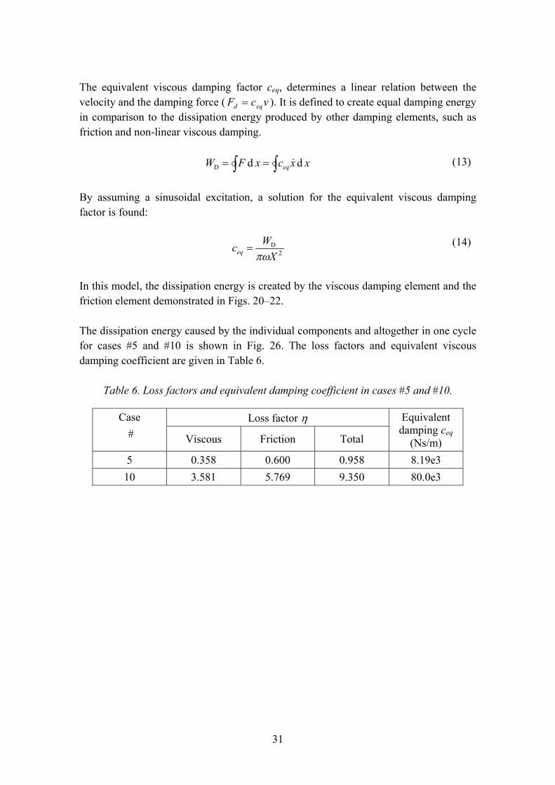
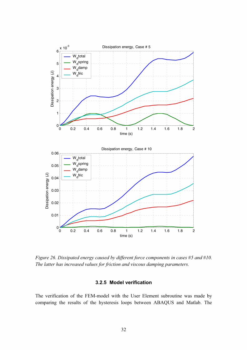
The dissipation energy caused by the individual components and altogether in one cycle for cases #5 and #10 is shown in Fig. 26. The loss factors and equivalent viscous damping coefficient are given in Table 6.
Table 6. Loss factors and equivalent damping coefficient in cases #5 and #10.
Loss factor η Case # Viscous Friction Total
Equivalent damping ceq
(Ns/m) 5 0.358 0.600 0.958 8.19e3 10 3.581 5.769 9.350 80.0e3
32
0 0.2 0.4 0.6 0.8 1 1.2 1.4 1.6 1.8 20
0.01
0.02
0.03
0.04
0.05
0.06Dissipation energy, Case # 10
time (s)
Dis
sipa
tion
ener
gy (
J)
0 0.2 0.4 0.6 0.8 1 1.2 1.4 1.6 1.8 20
1
2
3
4
5
6x 10
-3 Dissipation energy, Case # 5
time (s)
Dis
sipa
tion
ener
gy (
J)Wdtotal
Wdspring
Wddamp
Wdfric
Wdtotal
Wdspring
Wddamp
Wdfric
Figure 26. Dissipated energy caused by different force components in cases #5 and #10. The latter has increased values for friction and viscous damping parameters.
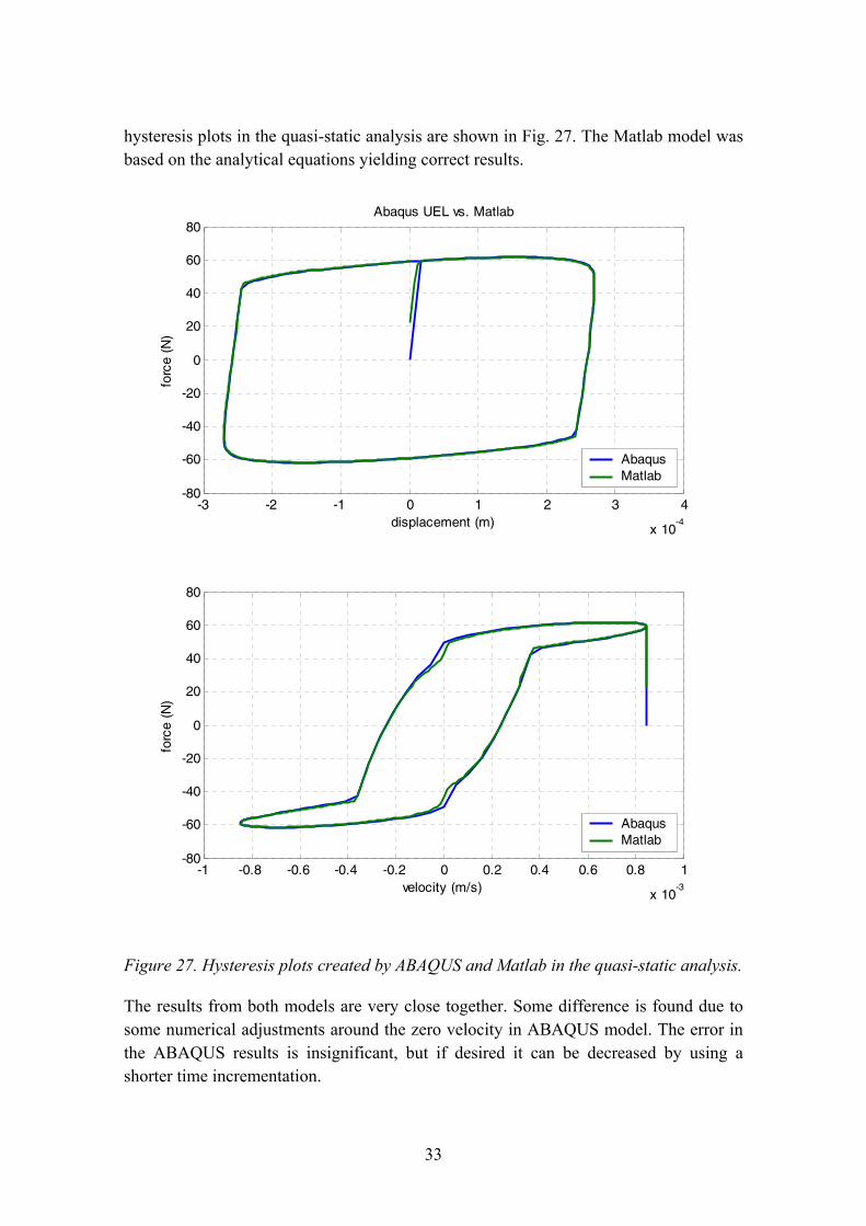
3.2.5 Model verification
The verification of the FEM-model with the User Element subroutine was made by comparing the results of the hysteresis loops between ABAQUS and Matlab. The
33
hysteresis plots in the quasi-static analysis are shown in Fig. 27. The Matlab model was based on the analytical equations yielding correct results.
-3 -2 -1 0 1 2 3 4
x 10-4
-80
-60
-40
-20
0
20
40
60
80Abaqus UEL vs. Matlab
displacement (m)
forc
e (N
)
AbaqusMatlab
-1 -0.8 -0.6 -0.4 -0.2 0 0.2 0.4 0.6 0.8 1
x 10-3
-80
-60
-40
-20
0
20
40
60
80
velocity (m/s)
forc
e (N
)
AbaqusMatlab
Figure 27. Hysteresis plots created by ABAQUS and Matlab in the quasi-static analysis.
The results from both models are very close together. Some difference is found due to some numerical adjustments around the zero velocity in ABAQUS model. The error in the ABAQUS results is insignificant, but if desired it can be decreased by using a shorter time incrementation.
34
4. Conclusions Several different models have been published to simulate the MR-damper dynamics. Some of them are very complicated to implement into the finite element purposes or they do not simulate the hysteresis phenomenon in both the displacement and the velocity domain correctly. Therefore, a simplified controllable spring-dashpot-friction element was implemented into previously developed UEL-code (Smart connector element) used with the ABAQUS/Standard. The FEM-model was verified by quasi-static studies using a single degree of freedom model and compared to the Matlab model. It was observed by numerical simulations that the smart connector element could be applied to simulate a similar dynamic response to that measured in the experiments. The relation between different force components is the most important factor in determining the force-velocity relationship in the MR-damper. Both the friction force and the viscous damping force need to be high compared to the elastic force to simulate similar hysteresis phenomena observed in the experiments.
The "smart connector element" is a promising element for structural dynamic analysis purposes in the time domain. It can be employed to analyze adaptive structures in which the MR-damper is utilized for the control of dynamic properties. Further studies are needed to characterize both the stiffness and damping characteristics instead of studying only the force and displacement responses of MR-devices. The stiffness and damping are the main variables of an individual MR-component as part of a vibrating structure.
35
References Carlson, J.D. & Jolly, M.R. MR-fluid, foam and elastomer devices, Mechatronics 10 (2000) p. 555�569.
Choi, S.-B. & Lee, S.-K. A Hysteresis Model for the Field-Dependent Damping Force of a Magnetorheological Damper, Journal of Sound and Vibration (2001) 245(2), p. 375� 383.
Dyke, S.J., Spencer, B.F. Jr., Sain, M.K. & Carlson, J.D. An experimental study of MR dampers for seismic protection, Smart Mater. Struct. 7 (1998) p. 693�703.
Encyclopedia of Smart Materials, http://www.mrw.interscience.wiley.com/esm/index.html.
Heinonen, J. Simulating Smart Connector by ABAQUS/Standard, VTT Internal Report prepared for the topic Embedded structural intelligence in VTT´s technology theme Intelligent Products and Systems, 2002, 16 p.
ABAQUS Theory Manual Version 5.7. Hibbitt, Karlsson, Sorensen.
ABAQUS/Standard User Manual Vol. 1, 2 and 3, Version 6.2. Hibbitt, Karlsson, Sorensen.
Genc, S. & Phulé P.P. Rheological properties of magnetorheological fluids, Smart Mater. Struct. 11 (2002) p. 140�146.
Jolly, M.R., Carlson, J.D. & Munoz, B.C. A model of the behaviour of magnetorheological materials, Smart Mater. Struct. 5 (1996) p. 607�614.
Li, W.H., Yao, G.Z., Chen, G., Yeo, S.H. & Yap, F.F. Testing and steady state modeling of a linear MR damper under sinusoidal loading, Smart Mater. Struct. 9 (2000) p. 95�102.
Liao, W.H. & Lai, C.Y. Harmonic analysis of a magnetorheological damper for vibration control, Smart Mater. Struct. 11 (2002) p. 288�296.
Lokander, M. & Stenberg, B. Performance of Isotropic Magnetorheological Rubber Materials, Polymer Testing, Volume 22, Issue 3, May 2003, p. 245�251.
Lord Corporation (http://www.mrfluid.com).
36
Oh, H-U. & Onoda, J. An experimental study of a semiactive magneto-rheological fluid variable damper for vibration suppression of truss structures, Smart Mater. Struct. 11 (2002) 156�162.
Thomson, W. T. Theory of Vibration with Applications, 4th Edition, Stanley Thornes Publishers Ltd., 1998 (reprinted), 546 p., ISBN 0-7487-4380-4.
Yang, G., Spencer, B.F. Jr., Carlson, J.D. & Sain, M.K. Large-scale MR fluid dampers: modeling and dynamic performance considerations, Engineering Structures 24 (2002) p. 309�323.

ISBN 951�38�6597�5 (URL: http://www.vtt.fi/inf/pdf/) ISSN 1459�7683 (URL: http://www.vtt.fi/inf/pdf/)


![ACATacat.or.th/download/acat_or_th/journal-4/04 - 04.pdf · APmin APmax Appendix G [1] AP APmax Overpressure Relief Damper Damper 12 Relief Damper Relief Damper (Vent) Fire Damper](https://img.pdfslide.net/doc/110x75/5f7cb481641db55595223717/-04pdf-apmin-apmax-appendix-g-1-ap-apmax-overpressure-relief-damper-damper.jpg)