Embed Size (px)
Citation preview
PROCESSING AND CHARACTERIZATION OF NANOPARTICLE AND CARBON
NANOTUBE REINFORCED CONTINUOUS FIBER CERAMIC
NANOCOMPOSITES BY PRECERAMIC POLYMER PYROLYSIS
A THESIS SUBMITTED TO THE GRADUATE DIVISION OF THE UNIVERSITY
OF HAWAI‘I AT MĀNOA IN PARTIAL FULFILLMENT OF THE REQUIREMENTS FOR
THE DEGREE OF
MASTER OF SCIENCE
IN
MECHANICAL ENGINEERING
AUGUST 2012
By:
Kaveh Khosroshahi
Thesis Committee:
Mehrdad N. Ghasemi Nejhad, Chairperson
Lloyd H. Hihara
Scott Miller

ii
We certify that we have read this thesis and that, in our opinion, it is satisfactory in scope and
quality as a thesis for the degree of Master of Science in Mechanical Engineering.
THESIS COMMITTEE
iii
ACKNOWLEDGEMENTS
The intellectual gains accumulated over the course of this project are many and varied, but the
deepest belongs, as it has been throughout the past two years, to my advisor, Dr. Mehrdad N.
Ghasemi Nejhad. He has been unfailingly generous with his time, constant support, day-to-day
guidance and advice rendered throughout this research. He indeed has provided a motivating,
enthusiastic and critical atmosphere during the many discussions we had. I do not think I could
do better than to follow his example. I also acknowledge Drs. Lloyd H. Hihara and Scott Miller
for serving on my thesis committee.
I wish to acknowledge the support of the Renewable Energy and Island Sustainability (REIS),
and Trex Enterprises, particularly Dr. Bill Goodman and Dr. Cliff Tanaka, for funding this
project . Sincere thanks to Dr. Vamshi Mohar Gudapati for dedicated support when needed,
making my work easier during the course of this research. Also, I would like to thank Mr. Darren
Welson, Director of Technologies at Starfre, Inc. for his informative discussions on preceramic
polymer technologies. Thanks are also due to Tina Carvalho for discussions on usage of SEM,
and the Geology Department for the usage of X-Ray Diffraction equipment. I am grateful to Dr.
Alex Luckas at KiON Corporation for the informative discussions and support regarding KiON
CERASET throughout this project. I am also grateful to BASF Corporation for the donation for
Glycerol Monooleate surfactant agent.
I would like to acknowledge the assistance of the support staff, particularly Joanne Yee and Greg
Pang, in the Mechanical Engineering Department who have made my work easier and enjoyable.
A special thanks to Robert Mcgehee for the speedy procurement of required raw materials and

iv
equipment. I am grateful to Mr. Ben Respicio and Mr. Northrup Castle of The College of
Engineering Shop and for their help in maintaining order within the laboratories.
Last but certainly not least, I am honored by the support extended by my family and relatives
during these years. Many thanks go to my father, Younes Khosroshahi and my mother, Homeyra
Khosroshahi for their support for many years.
v
ABSTRACT
In this work, two types of Continuous Fiber Ceramic Composites (CFCCs) were manufactured
using preceramic polymer pyrolysis (PIP) method for mechanical testing. Nicalon™ ceramic
grade silicon carbide fiber was used as the reinforcements, and KiON CERASET® preceramic
polymer was used as the matrix in this study. Further, the effects of nanoparticles, carbon
nanotubes, and the combination of the two, as CFCC reinforcements, compared to their base
CFCCs on processing and flexural mechanical performance of Nicalon/KiON CERASET®
CFCCs by PIP method have been investigated. Nicalon™ ceramic fiber was used as the primary
fabric for all four types of CFCCs in this work. KiON CERASET®
preceramic polymer was
mixed with nano size fillers in the presence of a surfactant agent to give a good dispersion of the
particles and was used as the nano-matrix. Initial work from nanoparticle reinforced CFCCs led
to further investigations on the effects of using carbon nanotubes, as well as their use in
conjuction with nanoparticles, on mechanical performance of continuous fiber ceramic
nanocomposites. Yttrium oxide nanoparticles with an average size of 27 nm were used as the
inclusion with weight percentage of 15%. Carbon nanotubes were grown directly on the surface
of Nicalon™ fabric via in-house chemical vapor deposition process. Characterization analysis
and dispersion studies of the samples using scanning electron microscopy were conducted. Four-
point bending test was also conducted to evaluate the flexural mechanical performance of the
ceramic nanocomposites samples at room temperature. Combination of nanoparticle and carbon
nanotube reinforced CFCCs, consistently showed significant improvement in flexural strength
and toughness compared to their counterparts without nanomaterial reinforcement or with only
one type of nano-reinforcement.
vi
TABLE OF CONTENTS
Acknowledgements……………………………………………………………..………iii
Abstract…………………………………………………………………………..……...v
List of Figures…………………………………………………………………..……….ix
List of Tables……………………………………………………………………..……..xi
Chapter 1: Introduction……………………….……………….……………….……..1
1.1. Nanotechnology…… …………….……………………………….……......5
1.2 .Continuous Fiber Ceramic Composites by PIP……..………………….......7
1.3. Motivation.……………………………………………….……….………..7
1.4. Goals of this research effort……………………………………………….10
1.5. Organization of Thesis.…………………………………….……………...10
Chapter 2: Manufacturing Methodology and Material System…………….……..11
2.1. Introduction………………………………………………………….…....11
2.2. Preceramic Polymer Technology………………………………………….11
2.3. Wet Lay-up Process……………………………………………………….13
2.4. Material System…………………………………………………..….……15
2.4.1. Preceramic Polymer…………………………………...………...15
2.4.2. Fiber Selection……………………………………...……….…..16
2.4.3. Nanoparticle Reinforcements……………………..…………….17
2.4.4 Carbon Nanotube Nanoforest Reinfrocement…..…………...…..18
vii
Chapter 3: Manufacturing Process……………………………………………….20
3.1. Introduction………………………………………………………....….20
3.2. Manufacturing of CFCC specimens for Mechanical Testing…………...20
3.2.1. Wet Lay-up of Fiber Cloths……………………………….….20
3.2.2. Compression Molding and Curing………………………..…..21
3.2.3. Pyrolysis / Reinfiltration……………….……………………..24
3.2.4 Vacuum Infiltration and Post-Infiltration Vacuuming
vs Passive Infiltration………………….…………………...27
3.3. Manufacturing Procedure for CFCCs …………….…………………...28
3.3.1 Manufacture of Pristine SiC CFCCs…….…………………....28
3.3.2. Manufacture of SiC CFCCs Reinfroced
with Y2O3 Nanoparticles…………….……………………29
3.3.3. Manufacture of SiC CFCCs Reinforced
with Carbon Nanotube NanoForest….……………………30
3.3.4. Manufacture of SiC CFCCs Reinfroced with Y2O3
Nanoparticles and Carbon Nanotube Nanoforest.…………31
Chapter 4: Processing Results, Characterization, and Discussion……….……33
4.1. Quality Assessment and Characterization of the CFCC test samples...33
4.2. Processing Results for Manufactured Pristine
and Nano-Reinforced CFCCs……………………………………..35
viii
Chapter 5: Mechanical Performance Evaluations………………….….………38
5.1. Introduction…………………………………………………….…….38
5.2. Four-point Flexure Tests, Results and Discussion
for the Pristine CFCCs…………………………………….……..41
5.3. Four-Point Flexure Tests, Results, and Discussion
for Y2O3 Nanoparticle Reinforced CFCCs…………….………..43
5.4. Four-Point Flexure Tests, Results, and Discussion
for Carbon Nanotube Nanoforest Reinforced CFCCs……..…….45
5.5. Four-Point Flexure Tests, Results, and Discussion for Y2O3
Nanoparticles and Carbon Nanotube
Nanoforest Reinforced CFCCs……………………..……………47
5.6: Result Comparison and Discussion of Pristine
and Nano-Reinforced CFCCs………………………..………….49
Chapter 6: Conclusions and Future Work...…………………………..……...54
References………………………………………………………………...……..57
ix
LIST OF FIGURES
Figure 1.1: Failure modes for Monolithic Ceramic vs CFCCs………………………….3
Figure 1.2: Advantages of using CFCCs at elevated temperatures……………….……..4
Figure 3.1: Aluminum manufacturing mold…………………………………………......22
Figure 3.2: Compression molding machine...…………………………………….……...22
Figure 3.3: Compression molding machine cure cycle…………………………….…….23
Figure 3.4: Cured green ceramic composite plate..…………………………………..….24
Figure 3.5: Cured and cut green ceramic composite beams…………………………......24
Figure 3.6: Pyrolysis furnace…………………………………………………………….25
Figure 3.7: Thermal cycle for pyrolysis……………………………………….…………26
Figure 3.8: “Prisitne” CFCC manufacturing methodology……………..…….…….…..27
Figure 3.9: Modified Pelican case ………………………………………………………28
Figure 3.10: Nanoparticle filled CFCC manufacturing methodology………………..…30
Figure 3.11: Carbon nanotube reinforced CFCC manufacturing methodology………...31
Figure 3.12: Nanoparticle and carbon nanotube reinforced CFCC manufacturing
methodology……………………………………………………………………….…….32
Figure 4.1: SEM images of Nicalon™
SiC fabric…………………….…………….……33
Figure 4.2: Unifomr dispersion of 15wt% Y2O3 nanoparticles……….…………….…..34
Figure 4.3: Comparison of cumulative wight gain in different types of CFCCS after each
pyrolysis cycle…………………………………………………………………………...36
Figure 5.1: A typical manufactured CFCC test specimens………………………….......38
x
Figure 5.2: Schematic of four-point flexure test, ASTM C1341…………………...........39
Figure 5.3: Four-point bending test fixture………………………………………………41
Figure 5.4: Moment diagram for 3-point bending test…………………………………...41
Figure 5.5: Moment diagram for 4-point bending test……………………………..…….42
Figure 5.6: A typical sample failed at its mid-span……………………………..….…….42
Figure 5.7 Load-deflection curves for obtained “Pristine” CFCCs……………...............43
Figure 5.8: Load-deflection curves for obtained “Pristine+NP” CFCCs……….….…….45
Figure 5.9: Load-deflection curves for obtained “Pristine+NF” CFCCs……………..….47
Figure 5.10: Load-deflection curves for obtained “Pristine+NP+NF” CFCCs………….49
Figure 5.11: Flexural strength comparison for all four types of CFCCs…………...........51
Figure 5.12: Toughness comparison for all four types of CFCCs……………….............52
Figure 5.13: Elastic moduli comparison for all four types of CFCCs……………….......53
Figure 5.14: average strain-to-failure comparison for all four types of CFCCs.………..53
Figure 5.15: average deflection-to-failure comparison for all four types of CFCCs..…..54
xi
LIST OF TABLES
Table 2.1: Properties of KiON CERASET®……………………………………………16
Table 2.2: Specifications and Properties of Fibers………………………………………17
Table 2.3: Specifications of Nanoparticles……………………………………………....17
Table 4.1: Processing results for manufactured CFCCs…………………………….......35
Table 5.1: Four-point bending test results for “Pristine” specimens…………………….43
Table 5.2: Mechanical properties from four-point bending test results…………………44
Table 5.3: Four-point bending test results for “Pristine+NP” specimens…………….….45
Table 5.4: Mechanical properties from four-point bending test results…………………46
Table 5.5: Four-point bending test results for “Pristine+NF” specimens…………….….47
Table 5.6: Mechanical properties from four-point bending test results…………………48
Table 5.7: Four-point bending test results for “Pristine+NP+NF” specimens…………..49
Table 5.8: Mechanical properties from four-point bending test results…………………50
Table 5.9: Compiled mechanical properties for all four types of CFCCs………………50
1
CHAPTER 1
INTRODUCTION
Ceramic materials have various advantages over metallic materials and their alloys for
high temperature applications. These applications in aerospace fields include rocket
exhaust nozzles, heat shields and aeronautic jet engine components [1]. Structural
ceramics and composites have applications in areas including energy generation,
environment, space, transportation and microelectronics [2]. Long-term mechanical
reliability is a key issue in their ultimate use for a specific application. The future
opportunities for the use of advanced ceramics and various types of ceramic matrix
composites in aerospace applications include DoD related applications in aircraft,
missiles and spacecraft, and civilian applications in aircraft and space vehicles [3]. This is
due to ceramic’s lower density, high temperature strength, and corrosion and oxidation
resistance capabilities of the ceramic matrix composites [3]. Traditional monolithic
ceramics meet most of the requirements for these applications; however, due to their
brittle nature and lack of toughness, they cannot be used as the ideal material of choice.
Reinforcement of ceramic materials is a promising method for their toughness
improvement. Polymer matrix composites (PMCs) currently account for most of the
composite materials used in the gas turbine, despite their relatively low temperature
capability of typically less than 150°C [4]. Metal matrix composites (MMCs) are
attractive for application at intermediate temperatures while ceramic matrix composites
(CMCs) offer exciting possibilities for very high temperature applications where loads
are modest [5]. Ceramic Matrix Composites (CMCs) combine reinforcing ceramic phases
2
with a ceramic matrix to create materials with new and superior properties. In ceramic
matrix composites, the primary goal of the ceramic reinforcement is to provide toughness
to an otherwise brittle ceramic matrix. CMCs are being developed for applications that
require light-weight structural materials, oxidation resistance, and high temperature
resistance capabilities including high strength and modulus [1-3]. Fillers can also be
added to the ceramic matrix during processing to enhance characteristics such as
electrical conductivity, thermal conductivity, thermal expansion, hardness, etc. The
combination of these characteristics makes ceramic matrix composites attractive
alternatives to traditional industrial materials such as high alloy steels and refractory
metals. An important type of ceramic matrix composite that is currently being
investigated is the Continuous Fiber-reinforced Ceramic Composite (CFCC). CMCs and
particularly CFCCs have attracted immense attention for use as high-temperature
structural materials [5-9]. CFCCs are significantly tougher and more damage tolerant
than their monolithic counterparts. These composites are attractive alternatives to
monolithic ceramics and whisker-fiber CMCs [6], since CFCCs fail with a tough, high
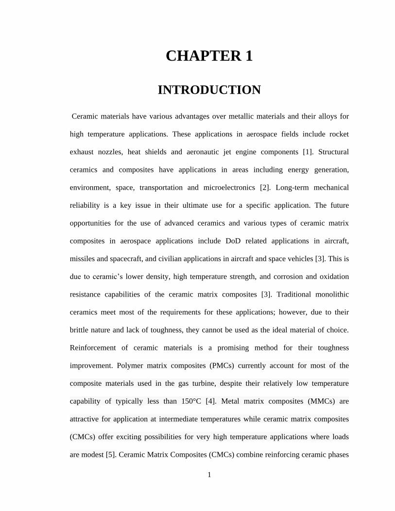
strain mode, whereas conventional ceramics fail with a rather brittle mode [7]. It is the
fiber reinforcement in the ceramic matrix that prevents catastrophic brittle failure, by
providing various energy dissipation processes during the crack propagation in the matrix
as see in Figure1.1.
3
Figure 1.1: Failure modes for Monolithic Ceramic vs. CFCCs [7]
In both the aerospace and automotive industry, there is an increasing demand for tough,
strong, and light weight materials to replace metals and their alloys as structural
materials. Future applications such as energy-efficient heat engines and high-subsonic
supersonic airplane and spacecraft will utilize high-performance structural materials in
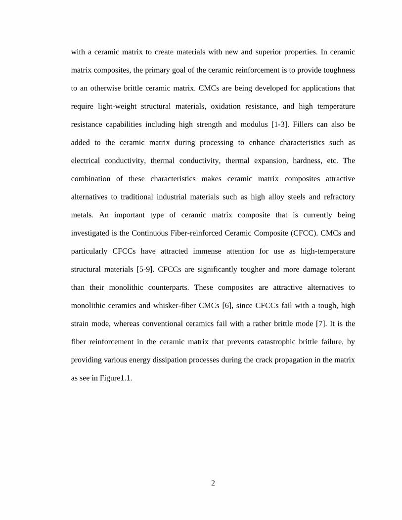
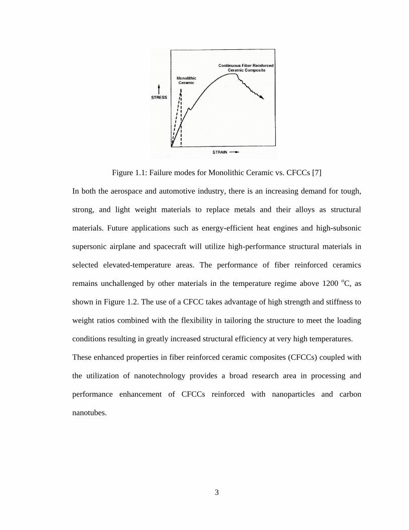
selected elevated-temperature areas. The performance of fiber reinforced ceramics
remains unchallenged by other materials in the temperature regime above 1200 oC, as
shown in Figure 1.2. The use of a CFCC takes advantage of high strength and stiffness to
weight ratios combined with the flexibility in tailoring the structure to meet the loading
conditions resulting in greatly increased structural efficiency at very high temperatures.
These enhanced properties in fiber reinforced ceramic composites (CFCCs) coupled with
the utilization of nanotechnology provides a broad research area in processing and
performance enhancement of CFCCs reinforced with nanoparticles and carbon
nanotubes.
4
Figure 1.2: Advantages of using CFCCs at elevated temperatures [9]
The preceramic polymer pyrolysis route to ceramic chemistry has attracted much
attention as it offers a promising and cost-effective way to manufacture CMCs/CFCCs
with little to no final machining [10-15] and parts with greater compositional
homogeneity [16-18]. Preceramic polymers are organo-metallic polymers which, after
curing, are chemically transformed during their pyrolysis step to yield a contributing
ceramic phase(s) in the final ceramic part. Other advantages of using the polymer
pyrolysis technique include the potential for high reproducibility of ceramic materials
with respect to chemical properties and physical characteristics, lower processing
temperatures and pressures, and improvement in the CMCs processing technique,
including faster thermal cycles, lower rejects, and high reliability of parts. Traditional
manufacturing techniques for CMCs (such as Chemical Vapor Deposition/Infiltration
(CVD/CVI), powder processing, Sol-gel processing, etc.) are time consuming and are in
the order of two weeks [19-21]. Homogeneous parts with complex geometries cannot be
manufactured by traditional methods due to the development of large density gradients
within the CMCs leading to non-uniform parts [20-21]. On the other hand, the
5
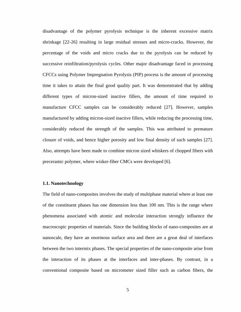
disadvantage of the polymer pyrolysis technique is the inherent excessive matrix
shrinkage [22-26] resulting in large residual stresses and micro-cracks. However, the
percentage of the voids and micro cracks due to the pyrolysis can be reduced by
successive reinfiltration/pyrolysis cycles. Other major disadvantage faced in processing
CFCCs using Polymer Impregnation Pyrolysis (PIP) process is the amount of processing
time it takes to attain the final good quality part. It was demonstrated that by adding
different types of micron-sized inactive fillers, the amount of time required to
manufacture CFCC samples can be considerably reduced [27]. However, samples
manufactured by adding micron-sized inactive fillers, while reducing the processing time,
considerably reduced the strength of the samples. This was attributed to premature
closure of voids, and hence higher porosity and low final density of such samples [27].
Also, attempts have been made to combine micron sized whiskers of chopped fibers with
preceramic polymer, where wisker-fiber CMCs were developed [6].
1.1. Nanotechnology
The field of nano-composites involves the study of multiphase material where at least one
of the constituent phases has one dimension less than 100 nm. This is the range where
phenomena associated with atomic and molecular interaction strongly influence the
macroscopic properties of materials. Since the building blocks of nano-composites are at
nanoscale, they have an enormous surface area and there are a great deal of interfaces
between the two intermix phases. The special properties of the nano-composite arise from
the interaction of its phases at the interfaces and inter-phases. By contrast, in a
conventional composite based on micrometer sized filler such as carbon fibers, the
6
interfaces between the filler and matrix constitute a much smaller surface-to-volume
fraction of the bulk materials, and hence influence the properties of the host structure to a
much smaller extent. The promise of nano-composites lies in their multifunctionality, the
possibility of realizing unique combination of properties unachievable with traditional
materials. The challenges in reaching this promise are tremendous. They include control
over the distribution in size and dispersion of the nanosize constituents, tailoring and
understanding the role of interfaces between structurally or chemically dissimilar phases
on bulk properties.
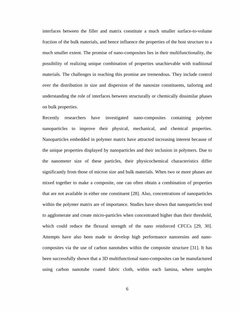
Recently researchers have investigated nano-composites containing polymer
nanoparticles to improve their physical, mechanical, and chemical properties.
Nanoparticles embedded in polymer matrix have attracted increasing interest because of
the unique properties displayed by nanoparticles and their inclusion in polymers. Due to
the nanometer size of these particles, their physicochemical characteristics differ
significantly from those of micron size and bulk materials. When two or more phases are
mixed together to make a composite, one can often obtain a combination of properties
that are not available in either one constituent [28]. Also, concentrations of nanoparticles
within the polymer matrix are of importance. Studies have shown that nanoparticles tend
to agglomerate and create micro-particles when concentrated higher than their threshold,
which could reduce the flexural strength of the nano reinforced CFCCs [29, 30].
Attempts have also been made to develop high performance nanoresins and nano-
composites via the use of carbon nanotubes within the composite structure [31]. It has
been successfully shown that a 3D multifunctional nano-composites can be manufactured
using carbon nanotube coated fabric cloth, within each lamina, where samples
7
interlaminar mechanical properties and delamination resistance were substantially
increased [32,33].The carbon-nanotube forests allow the fastening of adjacent plies in the
3D composite creating a velcro-like effect.
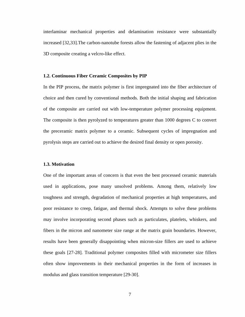
1.2. Continuous Fiber Ceramic Composites by PIP
In the PIP process, the matrix polymer is first impregnated into the fiber architecture of
choice and then cured by conventional methods. Both the initial shaping and fabrication
of the composite are carried out with low-temperature polymer processing equipment.
The composite is then pyrolyzed to temperatures greater than 1000 degrees C to convert
the preceramic matrix polymer to a ceramic. Subsequent cycles of impregnation and
pyrolysis steps are carried out to achieve the desired final density or open porosity.
1.3. Motivation
One of the important areas of concern is that even the best processed ceramic materials
used in applications, pose many unsolved problems. Among them, relatively low
toughness and strength, degradation of mechanical properties at high temperatures, and
poor resistance to creep, fatigue, and thermal shock. Attempts to solve these problems
may involve incorporating second phases such as particulates, platelets, whiskers, and
fibers in the micron and nanometer size range at the matrix grain boundaries. However,
results have been generally disappointing when micron-size fillers are used to achieve
these goals [27-28]. Traditional polymer composites filled with micrometer size fillers
often show improvements in their mechanical properties in the form of increases in
modulus and glass transition temperature [29-30].
8
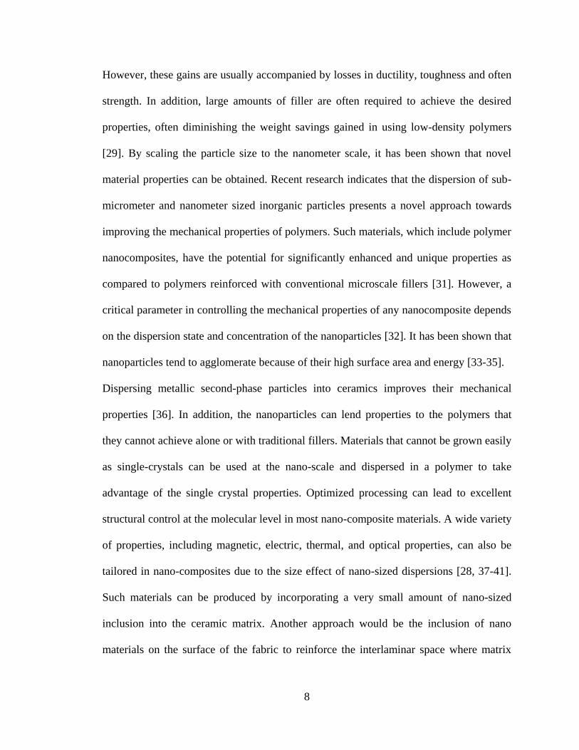
However, these gains are usually accompanied by losses in ductility, toughness and often
strength. In addition, large amounts of filler are often required to achieve the desired
properties, often diminishing the weight savings gained in using low-density polymers
[29]. By scaling the particle size to the nanometer scale, it has been shown that novel
material properties can be obtained. Recent research indicates that the dispersion of sub-
micrometer and nanometer sized inorganic particles presents a novel approach towards
improving the mechanical properties of polymers. Such materials, which include polymer
nanocomposites, have the potential for significantly enhanced and unique properties as
compared to polymers reinforced with conventional microscale fillers [31]. However, a
critical parameter in controlling the mechanical properties of any nanocomposite depends
on the dispersion state and concentration of the nanoparticles [32]. It has been shown that
nanoparticles tend to agglomerate because of their high surface area and energy [33-35].
Dispersing metallic second-phase particles into ceramics improves their mechanical
properties [36]. In addition, the nanoparticles can lend properties to the polymers that
they cannot achieve alone or with traditional fillers. Materials that cannot be grown easily
as single-crystals can be used at the nano-scale and dispersed in a polymer to take
advantage of the single crystal properties. Optimized processing can lead to excellent
structural control at the molecular level in most nano-composite materials. A wide variety
of properties, including magnetic, electric, thermal, and optical properties, can also be
tailored in nano-composites due to the size effect of nano-sized dispersions [28, 37-41].
Such materials can be produced by incorporating a very small amount of nano-sized
inclusion into the ceramic matrix. Another approach would be the inclusion of nano
materials on the surface of the fabric to reinforce the interlaminar space where matrix
9
originally employs. Carbon nanotubes have shown to provide excellent interlaminar
flexural properties compared to composites without any nano reinforcements within the
matrix [42]. Therefore, in this work, Continuous Fiber Ceramic Composites (CFCCs)
were manufactured using KiON CERASET preceramic polymer [43] without
nanoparticles, with nanoparticles only, with carbon nanotubes only, and with a
combination of nanoparticles as well as carbon nanotubes. The nanoparticles used in this
work, were yttrium oxide with an average size of 27 nm. The carbon nanotubes used, had
an average length of 40 nm and were grown directly on the surface of NicalonTM ceramic
grade silicon carbide plain weave fabric [44].
The effects of nanoparticle and carbon nanotube reinforcements on processing and
flexural mechanical performance of CFCCs using PIP were investigated and reported.
Among the nano reinforcements used, the combination of yttrium oxide nanoparticles and
carbon nanotube reinforcements performed the best in terms of nanocomposites property
enhancement. Significant improvements in the in-plane mechanical properties of carbon
nanotubes (CNTs) or nanoparticles reinforced composites compared to their unreinforced
counterparts have been reported [32, 38].
The optimum amount of nanoparticles in the composites was 15wt% desperesed
uniformly within the preceramic polymer. Here, we report an experimental investigation
on the effects of combined yttrium oxide nanoparticle and carbon nanotube nanoforest
reinforcements, on the processing and flexural properties of CFCCs.
10
1.4. Goals of this Research Effort
The primary objective of this research was to manufacture SiC/SiC, CFCCs employing
preceramic polymer pyrolysis/reinfiltration (PIP) route. Other goals of this research were:
i) To investigate the influence of nanoparticle as well as carbon nanotube reinforcements
on flexural mechanical performance of CFCCs, and ii) To determine the improvements in
mechanical properties of the combination of nanoparticle and carbon nanotube nanoforest
reinforcemed CFCCs. Mechanical performance of CFCCs were evaluated using four-
point bending test. SEM micrographs and processing results were used to determine the
part quality and performance of the manufactured specimens.
1.5. Organization of Thesis
The first chapter contains a general introduction to CFCCs, nanotechnology, and the
motivation for the current study. The manufacturing methodology, employed for the
manufacturing of the CFCCs used in this study are discussed in Chapter 2. A detailed
description of the manufacturing process involved, followed by a description of
manufacturing route for different types of samples are presented in Chapter 3.
Quality assessment, and processing results for different CFCC samples are discussed in
Chapter 4. Chapter 5 presents the four-point flexure test results for different sets of nano-
reinforced CFCC specimens, followed by comparison of meachanical property
improvements for nano-reinforced CFCCs. Finally, conclusions are made in Chapter 6.
11
CHAPTER 2
MANUFACTURING METHODOLOGY &
MATERIAL SYSTEM
2.1. Introduction
The Polymer Impregnation & Pyrolysis (PIP) process used to fabricate CFCCs is widely
recognized as a versatile method to fabricate large, complex-shaped structures. In
comparison with other ceramic composite fabrication processes, the PIP process offers
significantly greater flexibility. By utilizing low temperature forming and molding steps
typically used in organic matrix composites, the PIP approach allows one to use existing
equipment and processing technology to form the parts.
2.2. Preceramic Polymer Technology
When the field of producing ceramics by preceramic polymer pyrolysis was emerging in
the late 60’s and early 70’s, very few precursors were known. At that time, various
carbon products were used. A review of the history of producing non-oxide ceramics
from polymer pyrolysis is presented by Rice [15]. An investigative study was carried out
to identify other precursors and structure-yield trends, and determine the potentiality of
producing ceramics via the preceramic polymer pyrolysis route.
The pyrolysis of organometallic polymers, or other precursors was found to be a novel
method to manufacture ceramics. This extremely useful technique is widely applicable to
include silicon carbide, silicon nitride, and boron nitride ceramics. Instead of using
12
carbon polymers, silicon-based polymers are used to produce ceramics with high yield.
The polymer-derived ceramics that can be produced by preceramic polymer
pyrolysis include fibers, matrices, and coatings.
In precermic polymer technology, a polymer is used as a starting material. Since a
polymer is used as a precursor, conventional polymer manufacturing techniques can be
utilized to fabricate ceramics and ceramic matrix composites. These methods include
resin transfer molding, filament winding, pultrusion, wet lay-up using autoclave, etc. The
part is shaped in the polymer condition using conventional manufacturing techniques,
then cured and cross-linked to stabilize the shape of the part and finally is pyrolyzed to
partially convert the polymer into a ceramic. During the pyrolysis, a portion of the
polymer burns out and produces some combustion products that must be extracted from
the furnace. This leaves the part with some porosity that must be overcome with
subsequent reinfiltration and pyrolysis iterations through the cracks developed by residual
stresses until the density convergence through a weight gain criterion is achieved.
Pyrolysis is the necessary step of heating the part in order to convert the polymer matrix
into a stable ceramic phase.
This is carried out in a high temperature furnace under a non-reactive gaseous, i.e., inert
environment. Inert gases such as argon and nitrogen are used in preceramic polymer
pyrolysis. Repeated infiltration steps are carried out to increase the density of the
composite. With preceramic polymer fabrication, the number of infiltration steps used to
fill the voids and pores caused by pyrolysis controls the density and porosity of the
composite. The number of infiltration-pyrolysis steps range from 4 –10 depending on the
fiber material and char yield of the polymer. Densities of preceramic polymers typically
13
range from 1.1 to 1.2 g/cm3, with weight-based char yields ranging from 60% to over
90%.
The use of preceramic polymers overcomes many problems in processing conventional
binders, including high part rejection rates and low part reliability. This technology has
the advantage of fabricating and forming fiber-reinforced ceramic matrix composites that
were difficult to make via conventional binder techniques, and improvements in the CMC
processing technique such as lower processing temperature.
Preceramc polymer technology in conjuction with wet lay-up opens the possibility of
manufacturing complex-shaped CFCC’s, which are tougher and stronger than their short
fiber CMC counterparts.
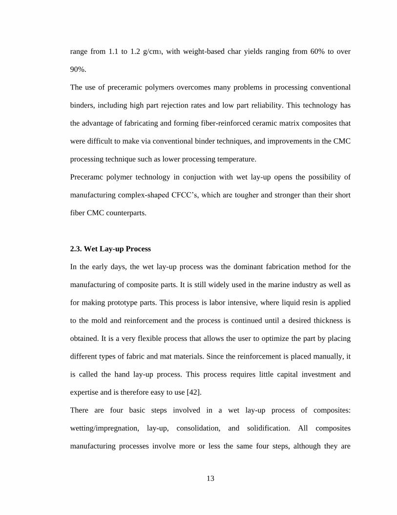
2.3. Wet Lay-up Process
In the early days, the wet lay-up process was the dominant fabrication method for the
manufacturing of composite parts. It is still widely used in the marine industry as well as
for making prototype parts. This process is labor intensive, where liquid resin is applied
to the mold and reinforcement and the process is continued until a desired thickness is
obtained. It is a very flexible process that allows the user to optimize the part by placing
different types of fabric and mat materials. Since the reinforcement is placed manually, it
is called the hand lay-up process. This process requires little capital investment and
expertise and is therefore easy to use [42].
There are four basic steps involved in a wet lay-up process of composites:
wetting/impregnation, lay-up, consolidation, and solidification. All composites
manufacturing processes involve more or less the same four steps, although they are

14
accomplished in different ways. During the impregnation stage, the fibers and resins are
mixed together to form a lamina. In this process, each fabric layer is wetted with resin
using a squeezing roller for proper impregnation. The purpose of this step is to make sure
that the resin flows entirely around all fibers. Viscosity, surface tension, and capillary
action are the main parameters affecting the impregnation process. During the Lay-up
stage, the desired composite thickness is built up by stacking various layers of wetted
fibers on top of each other until the desires thickness is obtained. Performance of the
composite structure relies heavily on fiber orientation and lay-up sequence.
Consolidation involves in creating intimate contact between each layer of prepreg or
lamina. This step ensures that all entrapped air is removed from the in-between layers by
resin flow during the processing. Consolidation is an important step to obtain good part
quality. Poorly consolidated parts will have voids and dry spots. Proper consolidation is
obtained when the applied pressure is equally shared by both the resin and fiber structure.
The final step is solidification, which may take less than a minute for thermoplastics or
may take up to 120 minutes or more for thermosets. Vacuum and/or pressure is
maintained during the period. The lower the solidification time, the higher the production
rate achievable by the process. In thermoset composites, the rate of solidification depends
on the resin formulation and cure kinetics. Heat is supplied during processing to expedite
the cure rate of the resin and initiate linking in some cases.
On a commercial scale, this process is widely used for making boats, windmill blades,
storage tanks, and swimming pools. Due to its process simplicity and little capital
investment, this process is widely used for making prototype parts. Test coupons for
15
performing various tests for the evaluation of reinforcements as well as resins are also
made using this process [42].
2.4. Materials System
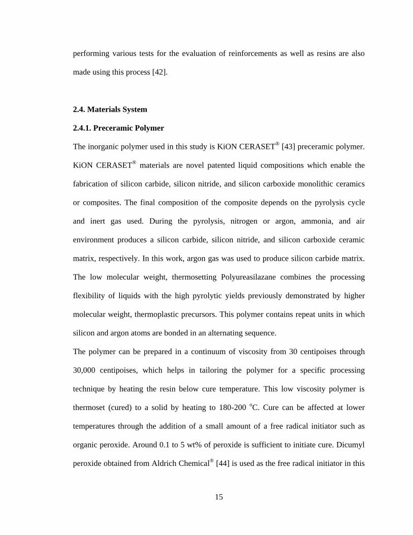
2.4.1. Preceramic Polymer
The inorganic polymer used in this study is KiON CERASET®
[43] preceramic polymer.
KiON CERASET®
materials are novel patented liquid compositions which enable the
fabrication of silicon carbide, silicon nitride, and silicon carboxide monolithic ceramics
or composites. The final composition of the composite depends on the pyrolysis cycle
and inert gas used. During the pyrolysis, nitrogen or argon, ammonia, and air
environment produces a silicon carbide, silicon nitride, and silicon carboxide ceramic
matrix, respectively. In this work, argon gas was used to produce silicon carbide matrix.
The low molecular weight, thermosetting Polyureasilazane combines the processing
flexibility of liquids with the high pyrolytic yields previously demonstrated by higher
molecular weight, thermoplastic precursors. This polymer contains repeat units in which
silicon and argon atoms are bonded in an alternating sequence.
The polymer can be prepared in a continuum of viscosity from 30 centipoises through
30,000 centipoises, which helps in tailoring the polymer for a specific processing
technique by heating the resin below cure temperature. This low viscosity polymer is
thermoset (cured) to a solid by heating to 180-200 oC. Cure can be affected at lower
temperatures through the addition of a small amount of a free radical initiator such as
organic peroxide. Around 0.1 to 5 wt% of peroxide is sufficient to initiate cure. Dicumyl
peroxide obtained from Aldrich Chemical®
[44] is used as the free radical initiator in this
16
work. Typical ceramic yields, an indication of mass conversion to ceramic material, as
measured by thermal gravimetric analysis (TGA), is about 75% for KiON CERASET®
in
nitrogen and argon, and about 95% in air [43]. Table 2.1 shows the physical properties of
KiON CERASET®
.
Table 2.1: Properties of KiON CERASET®
[43]
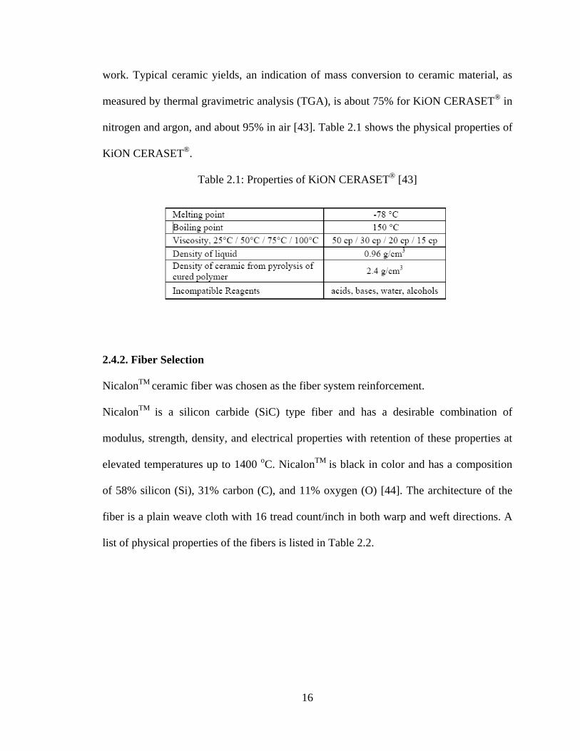
2.4.2. Fiber Selection
NicalonTM
ceramic fiber was chosen as the fiber system reinforcement.
NicalonTM
is a silicon carbide (SiC) type fiber and has a desirable combination of
modulus, strength, density, and electrical properties with retention of these properties at
elevated temperatures up to 1400 oC. Nicalon
TM is black in color and has a composition
of 58% silicon (Si), 31% carbon (C), and 11% oxygen (O) [44]. The architecture of the
fiber is a plain weave cloth with 16 tread count/inch in both warp and weft directions. A
list of physical properties of the fibers is listed in Table 2.2.
17
Table 2.2: Specifications and Properties of Fibers [44].
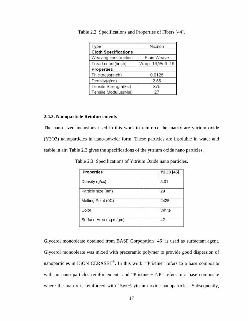
2.4.3. Nanoparticle Reinforcements
The nano-sized inclusions used in this work to reinforce the matrix are yttrium oxide
(Y2O3) nanoparticles in nano-powder form. These particles are insoluble in water and
stable in air. Table 2.3 gives the specifications of the yttrium oxide nano particles.
Table 2.3: Specifications of Yttrium Oxide nano particles.
Properties Y2O3 [45]
Density (g/cc) 5.01
Particle size (nm) 29
Melting Point (0C) 2425
Color White
Surface Area (sq.m/gm) 42
Glycerol monooleate obtained from BASF Corporation [46] is used as surfactant agent.
Glycerol monooleate was mixed with preceramic polymer to provide good dispersion of
nanoparticles in KiON CERASET®
. In this work, “Pristine” refers to a base composite
with no nano particles reinforcements and “Pristine + NP” refers to a base composite
where the matrix is reinforced with 15wt% yttrium oxide nanoparticles. Subsequently,
18
“Pristine + NF” refers to a base composite where the fibers are reinforced utilizing the
carbon nanotube nanoforest technology [32] and “Pristine+NP+NF” refers to a base
composite reinforced with both yttrium oxide nanoparticles as well as carbon nanotube
nanoforest.
The NP reinforced specimen are manufactured with preceramic polymer infiltration
pyrolysis (PIP) route, where the matrix for the initial forming as well as the first 2
reinfiltration cycles has nanoparticles inclusions and the rest of the infiltration matrix for
the remaining densification cycles does not.
2.4.4. Carbon Nanotube Nanoforest Reinforcements
The nano-sized insertions used in this work to reinforce the fibers are vertically aligned
carbon nanotubes. These nanotubes are grown perpendicular to the surface of the ceramic
grade NicalonTM
fabric and parallel to each other, in a dense and uniform manner called
nanoforest (NF). This technology, demonstrates the extraordinary strengths that carbon
nanotubes exhibit in their longitudinal direction and can be used to reinforce the space in
between the fibers where pure pristine pre-ceramic polymer matrix originally exists. This
gives the ceramic composite, a through the thickness strength by creating a matrix
interface of interlocking carbon nanotubes extending outward from the top and bottom
surfaces defined by each lamina, creating a 3-D composite laminate.
The length of the carbon nano-tubes used in this work, are in the range of 30 to 50 um
with the diameter of each carbon nanotube (multi-walled) in the order of 70 nm. The
nanotubes are grown directly on the ceramic grade NicalonTM
fabric which are stacked
up utilizing the wet lay-up manufacturing technique followed by curing via the

19
compression molding process. Specimens with only carbon nanotube nanoforest
“Prisitne+NF” and a combination of carbon nanotube nanoforest and yttrium oxide
nanoparticles “Prisitne+NP+NF” were manufactured to be compared and analyzed along
with other specimens mentioned in Section 2.4.3.
20
CHAPTER 3
MANUFACTURING PROCESS
3.1. Introduction
The manufacture of Continuous Fiber Ceramic Composites by Hand Lay-up using
Polymer Impregnation Pyrolysis consists of two steps as shown in the flow chart given
later in this chapter. The first step involves impregnating the fiber preform with
preceramic polymer and stacking them on top of each other to achieve a desired
thickness, followed by compression molding (see in Fig.3.1) and curing in the hot press
(see Fig. 3.2).
The second step consists of pyrolyzing the cured sample, thereby converting the
preceramic polymer into ceramic (in a high-temperature furnace shown later in this
chapter), followed by subsequent reinfiltration/pyrolysis cycles to achieve weight
convergence.
3.2. Manufacturing of CFCC specimens for Mechanical Testing
3.2.1. Wet Lay-up of Fiber Cloths
Plain weave Silicon Carbide and Carbon fiber cloths are used as the fiber architecture for
the manufacturing of the mechanical test specimens. KiON CERASET®
preceramic
polymer is the matrix used in the current study. The thickness of the fiber preform was
measured using a micrometer, which was approximately 0.0125’’ for the SiC cloth. The
preform was cut into dimensions of 6’’ x 4’’ layers from the roll.
21
For the manufacturing of the mechanical test samples, 3 layers of SiC were used for each
plate. In this process, initially each layer of fiber preform is properly impregnated with
the polymer. Special care was taken to wet the fibers with sufficient amount of polymer
for a good bonding between the laminae. After wetting the fiber preform, the wet laminae
were stacked on top of each other and, subsequently, pressed using a roller until a desired
thickness was obtained. Also, a foam brush was used to remove all the excess resin
before and after lay-up.
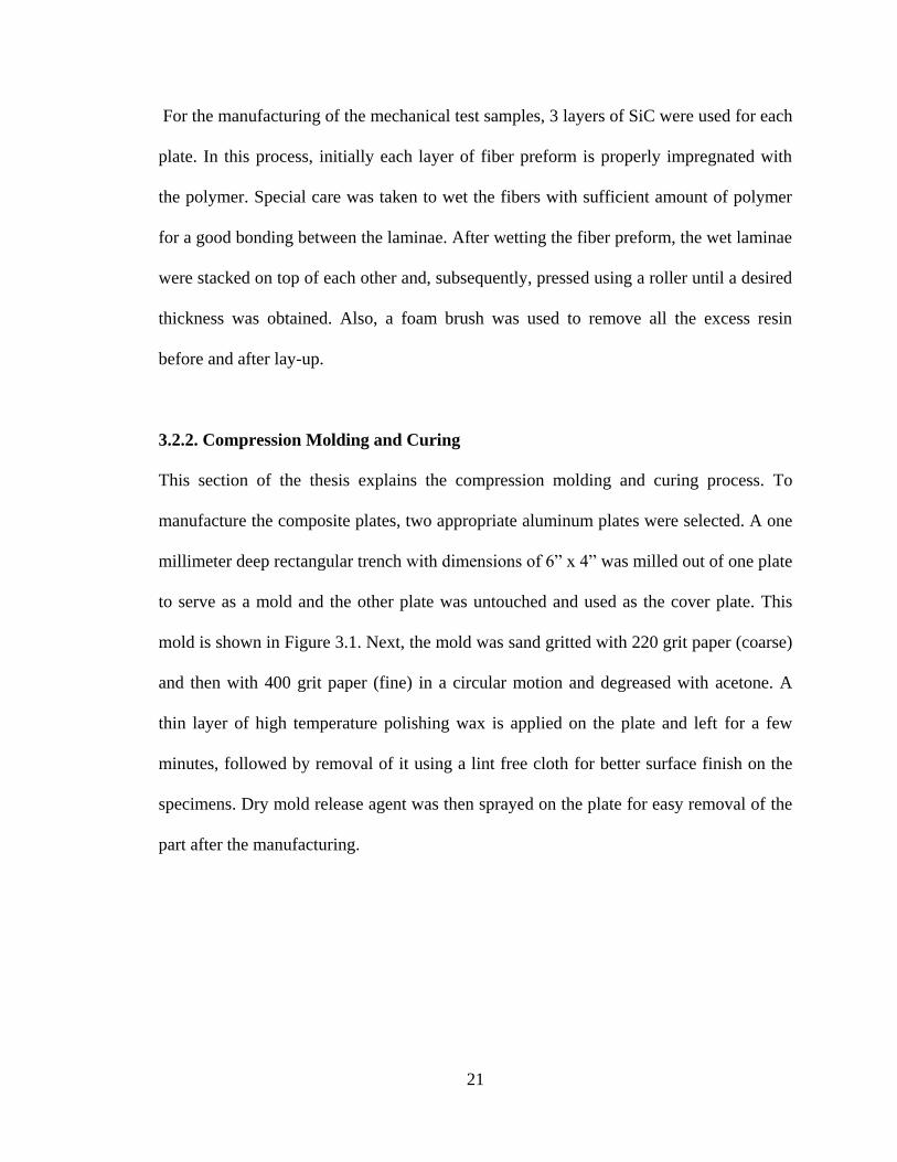
3.2.2. Compression Molding and Curing
This section of the thesis explains the compression molding and curing process. To
manufacture the composite plates, two appropriate aluminum plates were selected. A one
millimeter deep rectangular trench with dimensions of 6” x 4” was milled out of one plate
to serve as a mold and the other plate was untouched and used as the cover plate. This
mold is shown in Figure 3.1. Next, the mold was sand gritted with 220 grit paper (coarse)
and then with 400 grit paper (fine) in a circular motion and degreased with acetone. A
thin layer of high temperature polishing wax is applied on the plate and left for a few
minutes, followed by removal of it using a lint free cloth for better surface finish on the
specimens. Dry mold release agent was then sprayed on the plate for easy removal of the
part after the manufacturing.
22
.
Figure 3.1: Aluminum manufacturing mold.
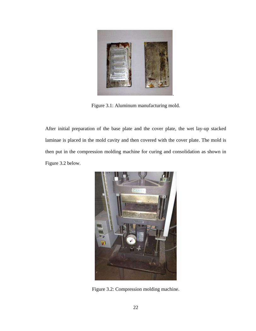
After initial preparation of the base plate and the cover plate, the wet lay-up stacked
laminae is placed in the mold cavity and then covered with the cover plate. The mold is
then put in the compression molding machine for curing and consolidation as shown in
Figure 3.2 below.
Figure 3.2: Compression molding machine.
23
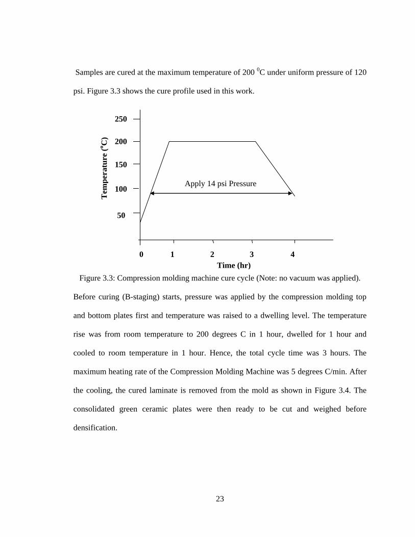
Samples are cured at the maximum temperature of 200 0C under uniform pressure of 120
psi. Figure 3.3 shows the cure profile used in this work.
Figure 3.3: Compression molding machine cure cycle (Note: no vacuum was applied).
Before curing (B-staging) starts, pressure was applied by the compression molding top
and bottom plates first and temperature was raised to a dwelling level. The temperature
rise was from room temperature to 200 degrees C in 1 hour, dwelled for 1 hour and
cooled to room temperature in 1 hour. Hence, the total cycle time was 3 hours. The
maximum heating rate of the Compression Molding Machine was 5 degrees C/min. After
the cooling, the cured laminate is removed from the mold as shown in Figure 3.4. The
consolidated green ceramic plates were then ready to be cut and weighed before
densification.
50
100
150
200
250
1 2 3 4 0
Tem
per
atu
re (
oC
)
Time (hr)
Apply 14 psi Pressure
24
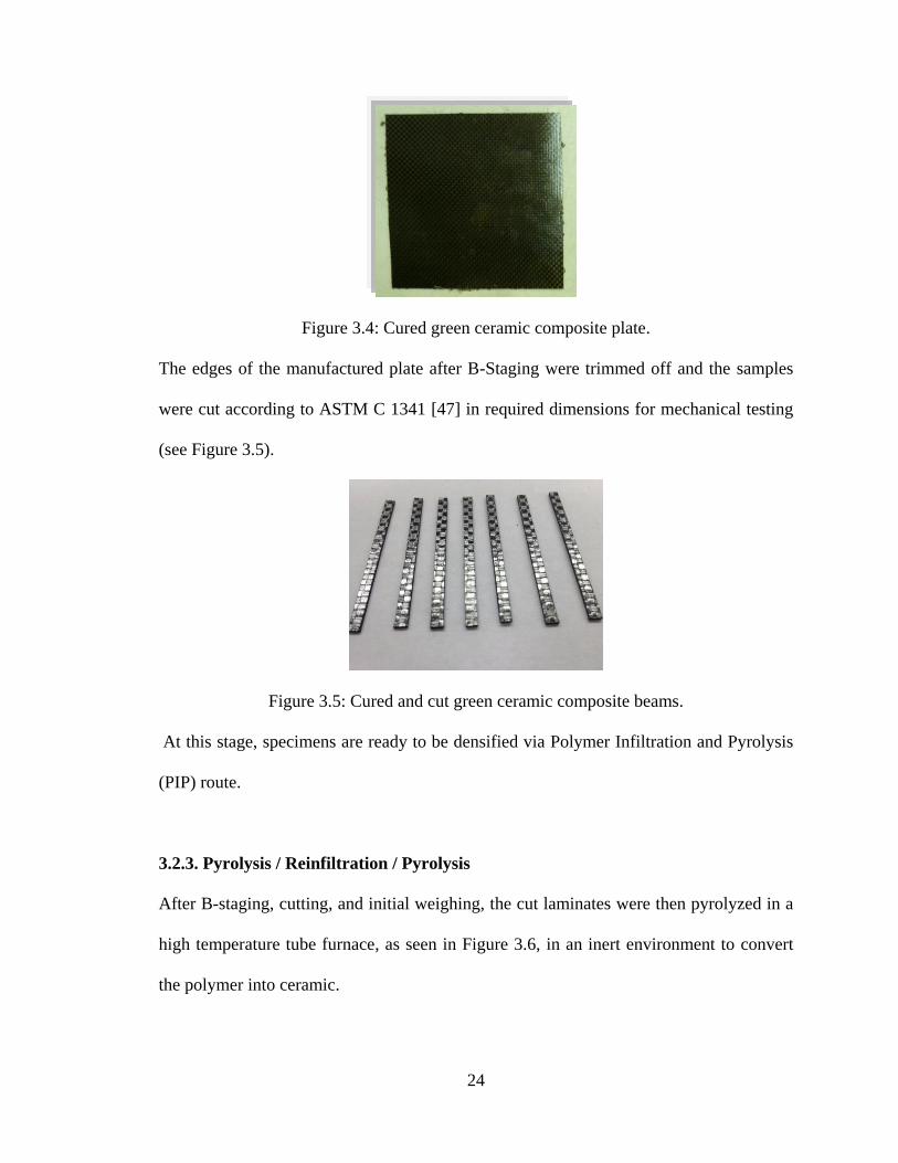
Figure 3.4: Cured green ceramic composite plate.
The edges of the manufactured plate after B-Staging were trimmed off and the samples
were cut according to ASTM C 1341 [47] in required dimensions for mechanical testing
(see Figure 3.5).
Figure 3.5: Cured and cut green ceramic composite beams.
At this stage, specimens are ready to be densified via Polymer Infiltration and Pyrolysis
(PIP) route.
3.2.3. Pyrolysis / Reinfiltration / Pyrolysis
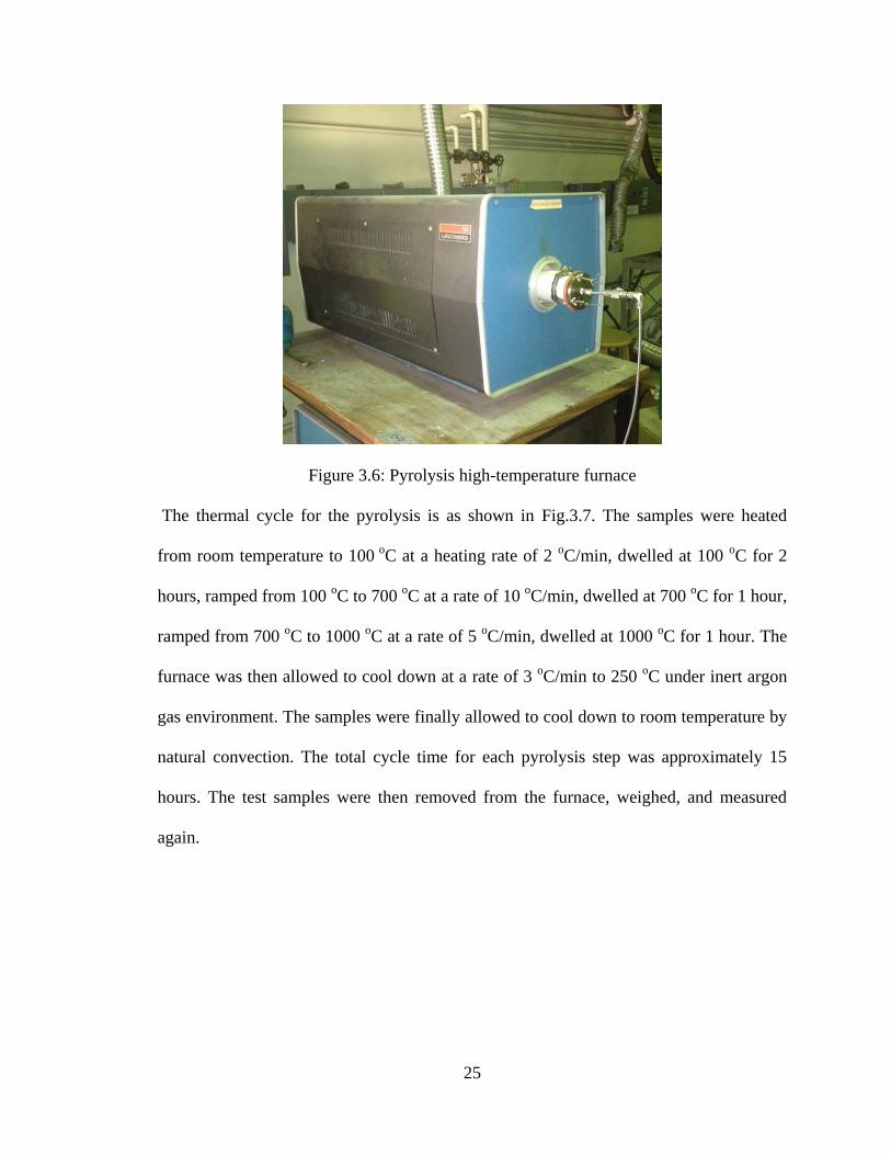
After B-staging, cutting, and initial weighing, the cut laminates were then pyrolyzed in a
high temperature tube furnace, as seen in Figure 3.6, in an inert environment to convert
the polymer into ceramic.
25
Figure 3.6: Pyrolysis high-temperature furnace
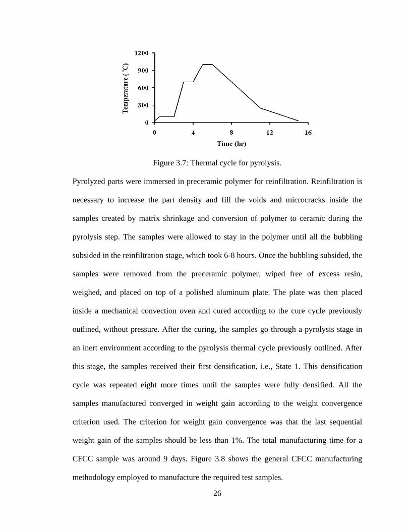
The thermal cycle for the pyrolysis is as shown in Fig.3.7. The samples were heated
from room temperature to 100 oC at a heating rate of 2
oC/min, dwelled at 100
oC for 2
hours, ramped from 100 oC to 700
oC at a rate of 10
oC/min, dwelled at 700
oC for 1 hour,
ramped from 700 oC to 1000
oC at a rate of 5
oC/min, dwelled at 1000
oC for 1 hour. The
furnace was then allowed to cool down at a rate of 3 oC/min to 250
oC under inert argon
gas environment. The samples were finally allowed to cool down to room temperature by
natural convection. The total cycle time for each pyrolysis step was approximately 15
hours. The test samples were then removed from the furnace, weighed, and measured
again.
26
Figure 3.7: Thermal cycle for pyrolysis.
Pyrolyzed parts were immersed in preceramic polymer for reinfiltration. Reinfiltration is
necessary to increase the part density and fill the voids and microcracks inside the
samples created by matrix shrinkage and conversion of polymer to ceramic during the
pyrolysis step. The samples were allowed to stay in the polymer until all the bubbling
subsided in the reinfiltration stage, which took 6-8 hours. Once the bubbling subsided, the
samples were removed from the preceramic polymer, wiped free of excess resin,
weighed, and placed on top of a polished aluminum plate. The plate was then placed
inside a mechanical convection oven and cured according to the cure cycle previously
outlined, without pressure. After the curing, the samples go through a pyrolysis stage in
an inert environment according to the pyrolysis thermal cycle previously outlined. After
this stage, the samples received their first densification, i.e., State 1. This densification
cycle was repeated eight more times until the samples were fully densified. All the
samples manufactured converged in weight gain according to the weight convergence
criterion used. The criterion for weight gain convergence was that the last sequential
weight gain of the samples should be less than 1%. The total manufacturing time for a
CFCC sample was around 9 days. Figure 3.8 shows the general CFCC manufacturing
methodology employed to manufacture the required test samples.
27
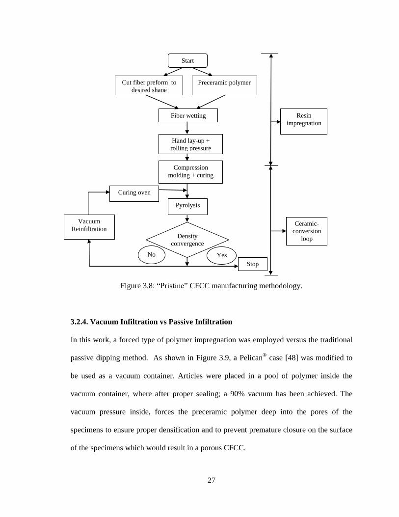
Figure 3.8: “Pristine” CFCC manufacturing methodology.
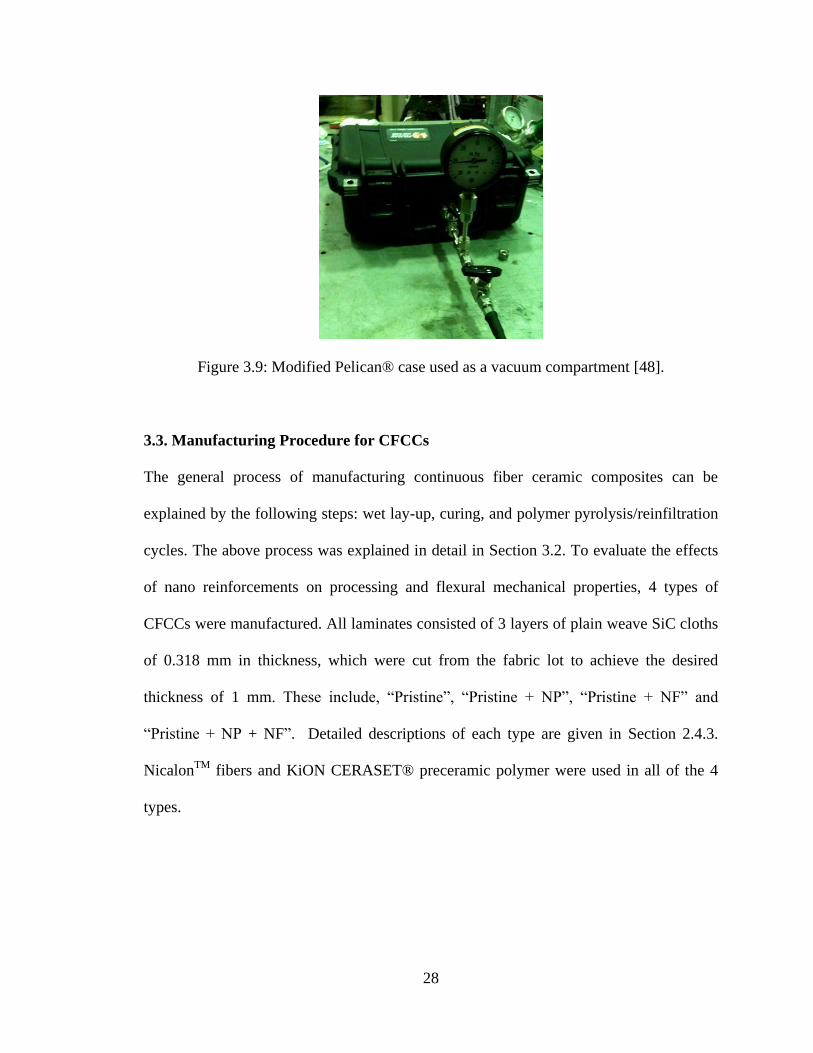
3.2.4. Vacuum Infiltration vs Passive Infiltration
In this work, a forced type of polymer impregnation was employed versus the traditional
passive dipping method. As shown in Figure 3.9, a Pelican®
case [48] was modified to
be used as a vacuum container. Articles were placed in a pool of polymer inside the
vacuum container, where after proper sealing; a 90% vacuum has been achieved. The
vacuum pressure inside, forces the preceramic polymer deep into the pores of the
specimens to ensure proper densification and to prevent premature closure on the surface
of the specimens which would result in a porous CFCC.
Start
Cut fiber preform to
desired shape Preceramic polymer
Fiber wetting
Hand lay-up +
rolling pressure
Compression
molding + curing
Pyrolysis
Density
convergence
No Yes
Vacuum
Reinfiltration
Resin
impregnation
Ceramic-
conversion
loop
Stop
Curing oven
28
Figure 3.9: Modified Pelican® case used as a vacuum compartment [48].
3.3. Manufacturing Procedure for CFCCs
The general process of manufacturing continuous fiber ceramic composites can be
explained by the following steps: wet lay-up, curing, and polymer pyrolysis/reinfiltration
cycles. The above process was explained in detail in Section 3.2. To evaluate the effects
of nano reinforcements on processing and flexural mechanical properties, 4 types of
CFCCs were manufactured. All laminates consisted of 3 layers of plain weave SiC cloths
of 0.318 mm in thickness, which were cut from the fabric lot to achieve the desired
thickness of 1 mm. These include, “Pristine”, “Pristine + NP”, “Pristine + NF” and
“Pristine + NP + NF”. Detailed descriptions of each type are given in Section 2.4.3.
NicalonTM
fibers and KiON CERASET® preceramic polymer were used in all of the 4
types.
29
3.3.1. Manufacture of Pristine SiC CFCCs
In this work, “Pristine” SiC CFCCs consists of SiC fabric and preceramic polymer only
without any type of nano-reinforcements and is used to establish a baseline for
comparison with nano-reinforced SiC CFCCs. Three layers of SiC fabric is wetted with
preceramic polymer and is stacked up using the wet lay-up teqnique, followed by curing
using the compression molding machine. Next, the edges of the laminated composite
plates are trimmed and samples of required dimensions (ASTM C 1341-06) are cut using
a diamond blade cutter. The cut samples are then pyrolyzed in a high temperature tube
furnace in an inert argon gas environment to convert the preceramic polymer into
ceramic. To convert the porous ceramic after the first pyrolysis step, subsequent
reinfiltration/pyrolysis are followed as outlined previously to achieve the required dense
CFCC test specimens. The manufacturing process remains the same as explained in
Section 3.2.3 and is shown in Figure 3.8.
3.3.2. Manufacture of SiC CFCCs Reinforced with Y2O3 Nanoparticles
Two different systems of CFCCs with Nanoparticle reinforcement were manufactured.
As explained in Section 2.4.3, “Pristine + NP” refers to sample reinforced with
nanoparticles only and “Pristine + NP + NF” refers to sample reinforced with both
nanoparticles and carbon nanotube nanoforest. For both cases, 15wt% of yttrium oxide
nanoparticles were mixed with Glycerol monooleate used as a surfactant agent and then
mixed with preceramic polymer. To provide good dispersion of nanoparticles in KiON
CERASET®
, the mixture is then sonicated for duration of 30 minutes to encourage
uniform and proper dispersion. The above matrix is used to wet lay-up the laminate. The
30
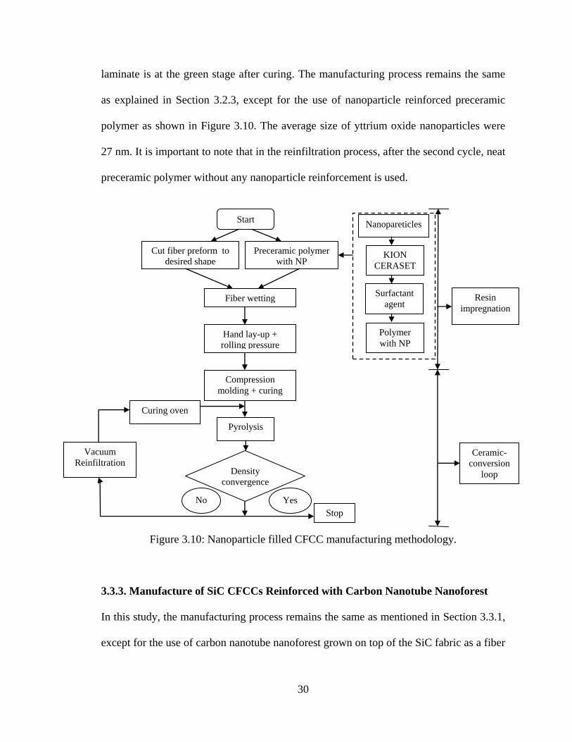
laminate is at the green stage after curing. The manufacturing process remains the same
as explained in Section 3.2.3, except for the use of nanoparticle reinforced preceramic
polymer as shown in Figure 3.10. The average size of yttrium oxide nanoparticles were
27 nm. It is important to note that in the reinfiltration process, after the second cycle, neat
preceramic polymer without any nanoparticle reinforcement is used.
Figure 3.10: Nanoparticle filled CFCC manufacturing methodology.
3.3.3. Manufacture of SiC CFCCs Reinforced with Carbon Nanotube Nanoforest
In this study, the manufacturing process remains the same as mentioned in Section 3.3.1,
except for the use of carbon nanotube nanoforest grown on top of the SiC fabric as a fiber
Start
Cut fiber preform to
desired shape
Preceramic polymer
with NP
Fiber wetting
Hand lay-up +
rolling pressure
Compression
molding + curing
Pyrolysis
Density
convergence
No
Resin
impregnation
Ceramic-
conversion
loop
KION
CERASET
Nanopareticles
Surfactant
agent
Polymer
with NP
Yes
Vacuum
Reinfiltration
Stop
Curing oven
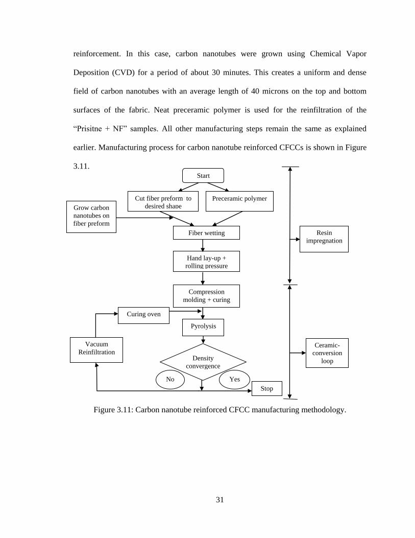
31
reinforcement. In this case, carbon nanotubes were grown using Chemical Vapor
Deposition (CVD) for a period of about 30 minutes. This creates a uniform and dense
field of carbon nanotubes with an average length of 40 microns on the top and bottom
surfaces of the fabric. Neat preceramic polymer is used for the reinfiltration of the
“Prisitne + NF” samples. All other manufacturing steps remain the same as explained
earlier. Manufacturing process for carbon nanotube reinforced CFCCs is shown in Figure
3.11.
Figure 3.11: Carbon nanotube reinforced CFCC manufacturing methodology.
Hand lay-up +
rolling pressure
Grow carbon
nanotubes on
fiber preform
Start
Cut fiber preform to
desired shape Preceramic polymer
Fiber wetting
Compression
molding + curing
Pyrolysis
Density
convergence
Resin
impregnation
Ceramic-
conversion
loop
No Yes
Vacuum
Reinfiltration
Stop
Curing oven
32
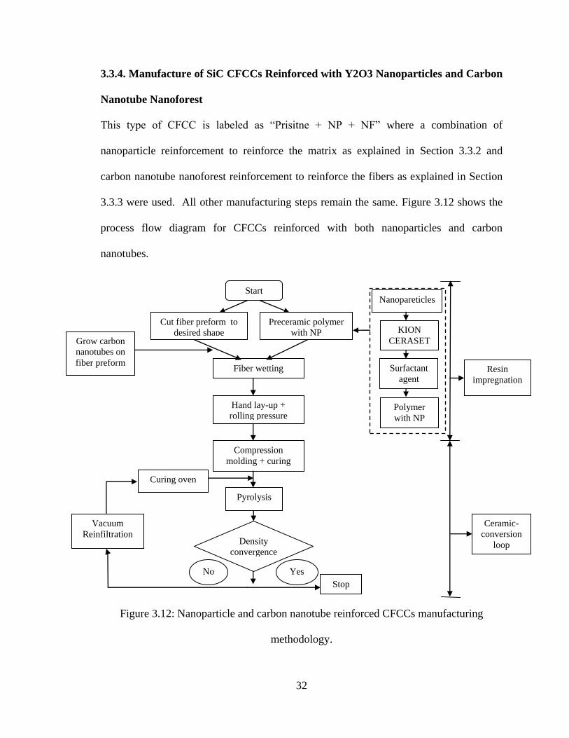
3.3.4. Manufacture of SiC CFCCs Reinforced with Y2O3 Nanoparticles and Carbon
Nanotube Nanoforest
This type of CFCC is labeled as “Prisitne + NP + NF” where a combination of
nanoparticle reinforcement to reinforce the matrix as explained in Section 3.3.2 and
carbon nanotube nanoforest reinforcement to reinforce the fibers as explained in Section
3.3.3 were used. All other manufacturing steps remain the same. Figure 3.12 shows the
process flow diagram for CFCCs reinforced with both nanoparticles and carbon
nanotubes.
Figure 3.12: Nanoparticle and carbon nanotube reinforced CFCCs manufacturing
methodology.
Start
Cut fiber preform to
desired shape
Preceramic polymer
with NP
Fiber wetting
Hand lay-up +
rolling pressure
Compression
molding + curing
Pyrolysis
Density
convergence
Resin
impregnation
Ceramic-
conversion
loop
KION
CERASET
Nanopareticles
Surfactant
agent
Polymer
with NP
Grow carbon
nanotubes on
fiber preform
No Yes
Vacuum
Reinfiltration
Stop
Curing oven
33
CHAPTER 4
PROCESSING RESULTS,
CHARACTERIZATION, AND DISCUSSION
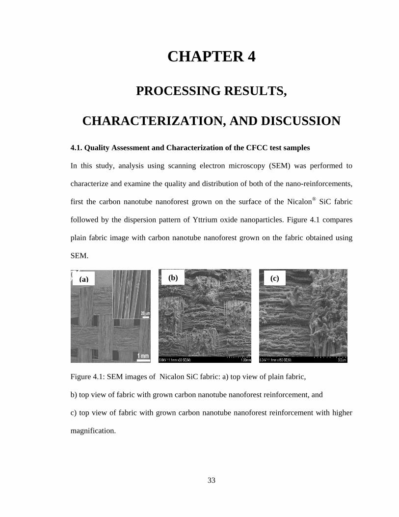
4.1. Quality Assessment and Characterization of the CFCC test samples
In this study, analysis using scanning electron microscopy (SEM) was performed to
characterize and examine the quality and distribution of both of the nano-reinforcements,
first the carbon nanotube nanoforest grown on the surface of the Nicalon®
SiC fabric
followed by the dispersion pattern of Yttrium oxide nanoparticles. Figure 4.1 compares
plain fabric image with carbon nanotube nanoforest grown on the fabric obtained using
SEM.
Figure 4.1: SEM images of Nicalon SiC fabric: a) top view of plain fabric,
b) top view of fabric with grown carbon nanotube nanoforest reinforcement, and
c) top view of fabric with grown carbon nanotube nanoforest reinforcement with higher
magnification.
(b) (c) (a)
34
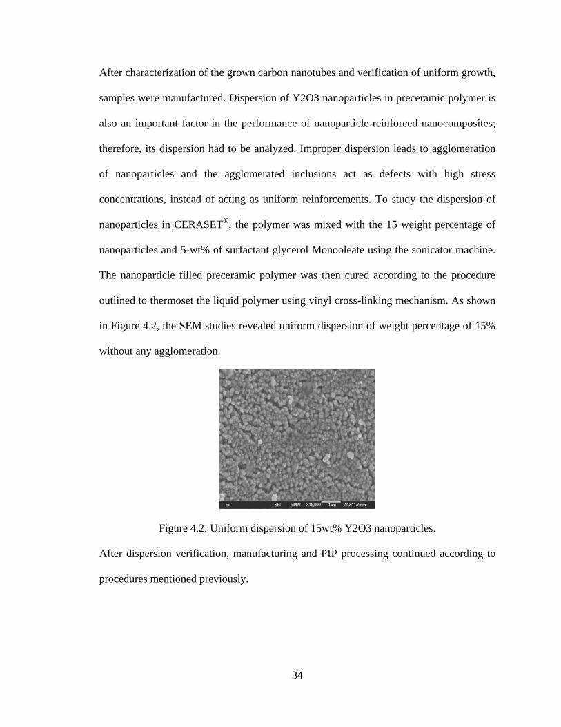
After characterization of the grown carbon nanotubes and verification of uniform growth,
samples were manufactured. Dispersion of Y2O3 nanoparticles in preceramic polymer is
also an important factor in the performance of nanoparticle-reinforced nanocomposites;
therefore, its dispersion had to be analyzed. Improper dispersion leads to agglomeration
of nanoparticles and the agglomerated inclusions act as defects with high stress
concentrations, instead of acting as uniform reinforcements. To study the dispersion of
nanoparticles in CERASET®
, the polymer was mixed with the 15 weight percentage of
nanoparticles and 5-wt% of surfactant glycerol Monooleate using the sonicator machine.
The nanoparticle filled preceramic polymer was then cured according to the procedure
outlined to thermoset the liquid polymer using vinyl cross-linking mechanism. As shown
in Figure 4.2, the SEM studies revealed uniform dispersion of weight percentage of 15%
without any agglomeration.
Figure 4.2: Uniform dispersion of 15wt% Y2O3 nanoparticles.
After dispersion verification, manufacturing and PIP processing continued according to
procedures mentioned previously.
35
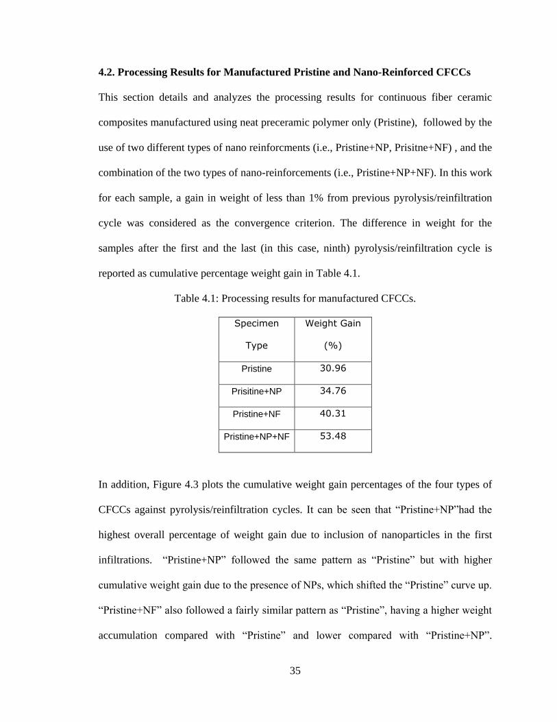
4.2. Processing Results for Manufactured Pristine and Nano-Reinforced CFCCs
This section details and analyzes the processing results for continuous fiber ceramic
composites manufactured using neat preceramic polymer only (Pristine), followed by the
use of two different types of nano reinforcments (i.e., Pristine+NP, Prisitne+NF) , and the
combination of the two types of nano-reinforcements (i.e., Pristine+NP+NF). In this work
for each sample, a gain in weight of less than 1% from previous pyrolysis/reinfiltration
cycle was considered as the convergence criterion. The difference in weight for the
samples after the first and the last (in this case, ninth) pyrolysis/reinfiltration cycle is
reported as cumulative percentage weight gain in Table 4.1.
Table 4.1: Processing results for manufactured CFCCs.
Specimen
Type
Weight Gain
(%)
Pristine 30.96
Prisitine+NP 34.76
Pristine+NF 40.31
Pristine+NP+NF 53.48
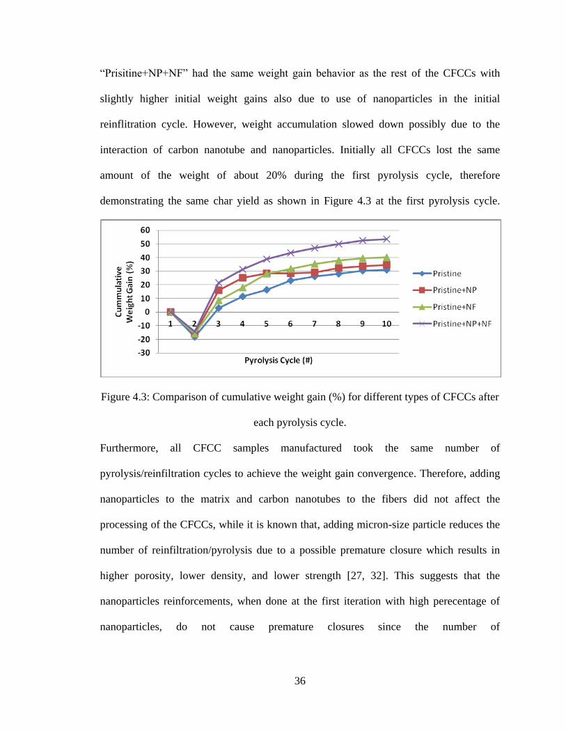
In addition, Figure 4.3 plots the cumulative weight gain percentages of the four types of
CFCCs against pyrolysis/reinfiltration cycles. It can be seen that “Pristine+NP”had the
highest overall percentage of weight gain due to inclusion of nanoparticles in the first
infiltrations. “Pristine+NP” followed the same pattern as “Pristine” but with higher
cumulative weight gain due to the presence of NPs, which shifted the “Pristine” curve up.
“Pristine+NF” also followed a fairly similar pattern as “Pristine”, having a higher weight
accumulation compared with “Pristine” and lower compared with “Pristine+NP”.
36
“Prisitine+NP+NF” had the same weight gain behavior as the rest of the CFCCs with
slightly higher initial weight gains also due to use of nanoparticles in the initial
reinflitration cycle. However, weight accumulation slowed down possibly due to the
interaction of carbon nanotube and nanoparticles. Initially all CFCCs lost the same
amount of the weight of about 20% during the first pyrolysis cycle, therefore
demonstrating the same char yield as shown in Figure 4.3 at the first pyrolysis cycle.
Figure 4.3: Comparison of cumulative weight gain (%) for different types of CFCCs after
each pyrolysis cycle.
Furthermore, all CFCC samples manufactured took the same number of
pyrolysis/reinfiltration cycles to achieve the weight gain convergence. Therefore, adding
nanoparticles to the matrix and carbon nanotubes to the fibers did not affect the
processing of the CFCCs, while it is known that, adding micron-size particle reduces the
number of reinfiltration/pyrolysis due to a possible premature closure which results in
higher porosity, lower density, and lower strength [27, 32]. This suggests that the
nanoparticles reinforcements, when done at the first iteration with high perecentage of
nanoparticles, do not cause premature closures since the number of

37
reinfiltartion/pyrolysis cycles required to achieve weight gain convergence with and
without nanoparticle and carbon nanotube reinforcements remained the same.
38
CHAPTER 5
MECHANICAL PERFORMANCES
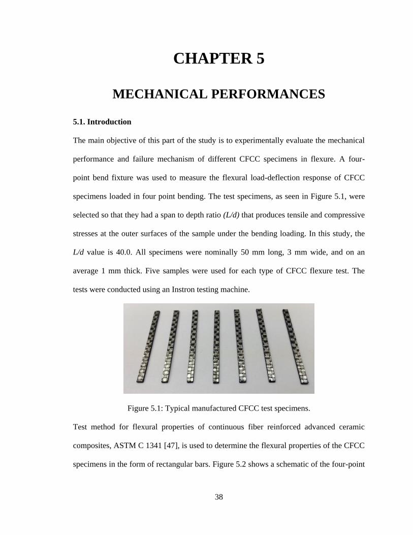
5.1. Introduction
The main objective of this part of the study is to experimentally evaluate the mechanical
performance and failure mechanism of different CFCC specimens in flexure. A four-
point bend fixture was used to measure the flexural load-deflection response of CFCC
specimens loaded in four point bending. The test specimens, as seen in Figure 5.1, were
selected so that they had a span to depth ratio (L/d) that produces tensile and compressive
stresses at the outer surfaces of the sample under the bending loading. In this study, the
L/d value is 40.0. All specimens were nominally 50 mm long, 3 mm wide, and on an
average 1 mm thick. Five samples were used for each type of CFCC flexure test. The
tests were conducted using an Instron testing machine.
Figure 5.1: Typical manufactured CFCC test specimens.
Test method for flexural properties of continuous fiber reinforced advanced ceramic
composites, ASTM C 1341 [47], is used to determine the flexural properties of the CFCC
specimens in the form of rectangular bars. Figure 5.2 shows a schematic of the four-point
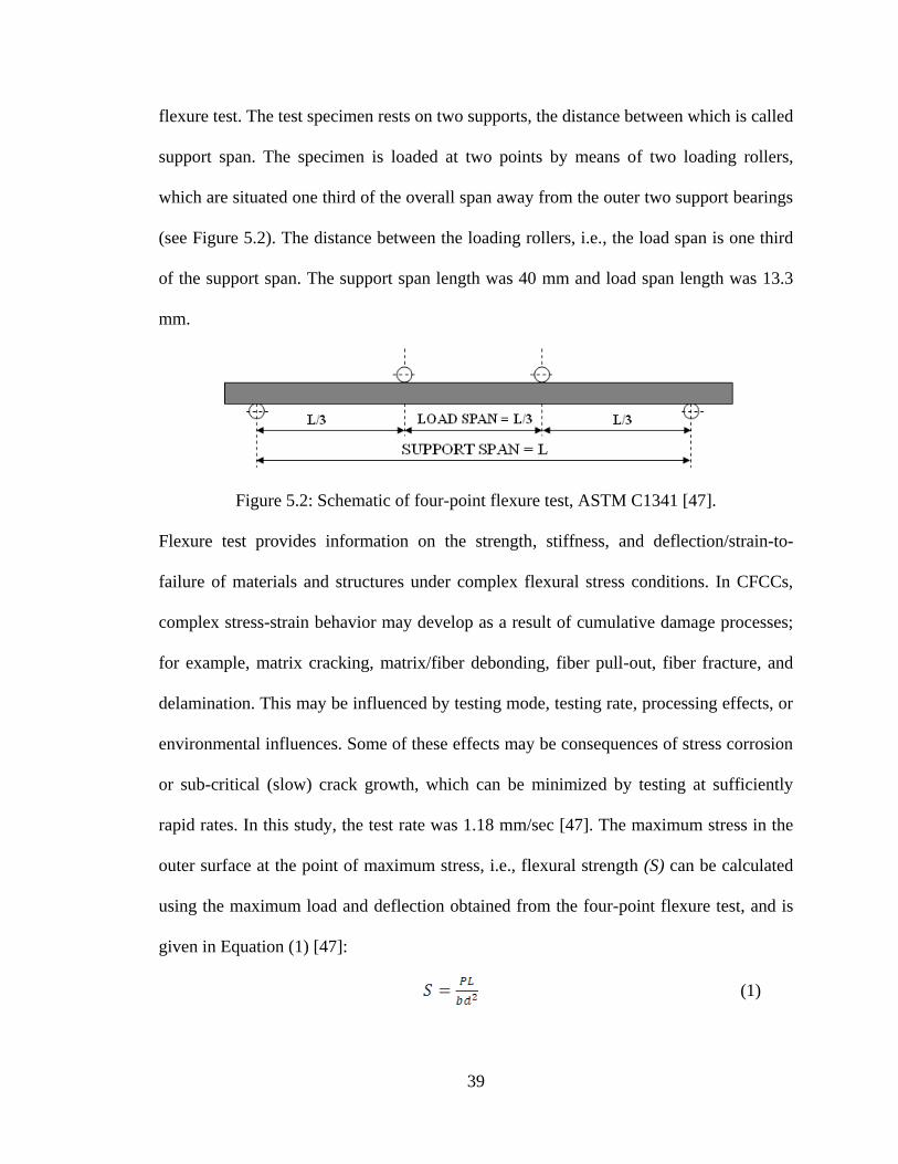
39
flexure test. The test specimen rests on two supports, the distance between which is called
support span. The specimen is loaded at two points by means of two loading rollers,
which are situated one third of the overall span away from the outer two support bearings
(see Figure 5.2). The distance between the loading rollers, i.e., the load span is one third
of the support span. The support span length was 40 mm and load span length was 13.3
mm.
Figure 5.2: Schematic of four-point flexure test, ASTM C1341 [47].
Flexure test provides information on the strength, stiffness, and deflection/strain-to-
failure of materials and structures under complex flexural stress conditions. In CFCCs,
complex stress-strain behavior may develop as a result of cumulative damage processes;
for example, matrix cracking, matrix/fiber debonding, fiber pull-out, fiber fracture, and
delamination. This may be influenced by testing mode, testing rate, processing effects, or
environmental influences. Some of these effects may be consequences of stress corrosion
or sub-critical (slow) crack growth, which can be minimized by testing at sufficiently
rapid rates. In this study, the test rate was 1.18 mm/sec [47]. The maximum stress in the
outer surface at the point of maximum stress, i.e., flexural strength (S) can be calculated
using the maximum load and deflection obtained from the four-point flexure test, and is
given in Equation (1) [47]:
(1)
40
where, P is the maximum load in the flexure test in Newton (N), b is the specimen width
in mm, d is the specimen thickness at the point of break in mm, and L is the length of the
specimen in mm. Equation (2) gives the flexural modulus of elasticity, E, for samples
tested in four point flexure [47]:
(2)
where, m is the slope of tangent to the initial straight-line portion of the load-deflection
curve (N/mm). Similarly, the maximum strain-to-failure was calculated using Equation
(3).
(3)
where, D is the deflection in mm. Toughness refers to the amount of energy per unit
volume that a material can absorb up to failure. As seen in Equation (4), toughness was
calculated using Equations (1) and (3).
(4)
Four-point bending test was chosen to quantify the performance of CFCCs as shown in
Figure 5.3. The four-point geometry is known to produce more reliable statistical data
when compared with three-point bending test, particularly for brittle materials [26]. For
obtaining a valid flexural strength by four-point bending test, a high support
span/thickness (L/d) ratio of about 40 was used to prevent shear failure and invalidation
of the tests.
41
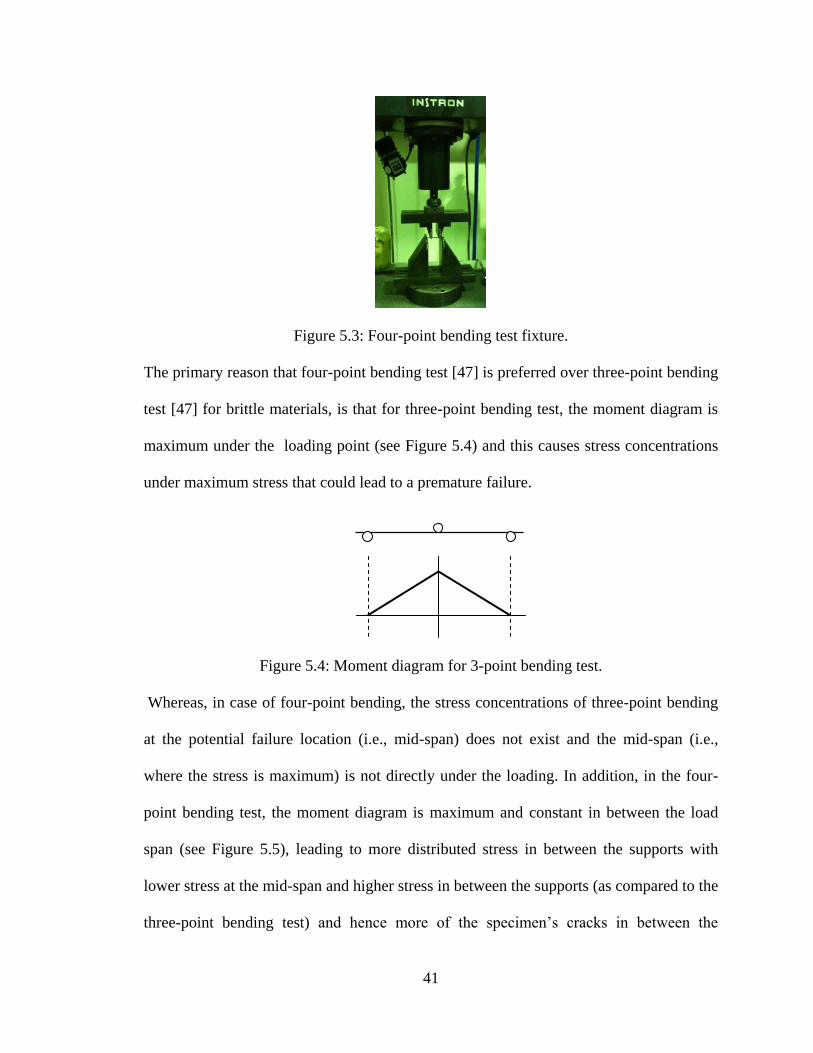
Figure 5.3: Four-point bending test fixture.
The primary reason that four-point bending test [47] is preferred over three-point bending
test [47] for brittle materials, is that for three-point bending test, the moment diagram is
maximum under the loading point (see Figure 5.4) and this causes stress concentrations
under maximum stress that could lead to a premature failure.
Figure 5.4: Moment diagram for 3-point bending test.
Whereas, in case of four-point bending, the stress concentrations of three-point bending
at the potential failure location (i.e., mid-span) does not exist and the mid-span (i.e.,
where the stress is maximum) is not directly under the loading. In addition, in the four-
point bending test, the moment diagram is maximum and constant in between the load
span (see Figure 5.5), leading to more distributed stress in between the supports with
lower stress at the mid-span and higher stress in between the supports (as compared to the
three-point bending test) and hence more of the specimen’s cracks in between the
42
supports are subjected to higher stresses, on the average, and hence a more reliable failure
may occur in this case for brittle material.
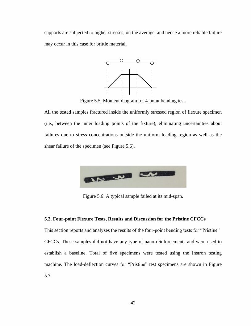
Figure 5.5: Moment diagram for 4-point bending test.
All the tested samples fractured inside the uniformly stressed region of flexure specimen
(i.e., between the inner loading points of the fixture), eliminating uncertainties about
failures due to stress concentrations outside the uniform loading region as well as the
shear failure of the specimen (see Figure 5.6).
Figure 5.6: A typical sample failed at its mid-span.
5.2. Four-point Flexure Tests, Results and Discussion for the Pristine CFCCs
This section reports and analyzes the results of the four-point bending tests for “Pristine”
CFCCs. These samples did not have any type of nano-reinforcements and were used to
establish a baseline. Total of five specimens were tested using the Instron testing
machine. The load-deflection curves for “Pristine” test specimens are shown in Figure
5.7.
43
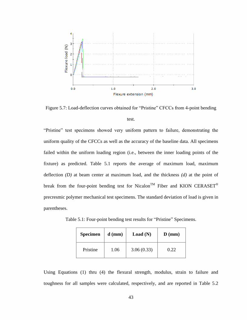
Figure 5.7: Load-deflection curves obtained for “Pristine” CFCCs from 4-point bending
test.
“Pristine” test specimens showed very uniform pattern to failure, demonstrating the
uniform quality of the CFCCs as well as the accuracy of the baseline data. All specimens
failed within the uniform loading region (i.e., between the inner loading points of the
fixture) as predicted. Table 5.1 reports the average of maximum load, maximum
deflection (D) at beam center at maximum load, and the thickness (d) at the point of
break from the four-point bending test for NicalonTM
Fiber and KION CERASET®
precresmic polymer mechanical test specimens. The standard deviation of load is given in
parentheses.
Table 5.1: Four-point bending test results for “Pristine” Specimens.
Specimen d (mm) Load (N) D (mm)
Pristine 1.06 3.06 (0.33) 0.22
Using Equations (1) thru (4) the flexural strength, modulus, strain to failure and
toughness for all samples were calculated, respectively, and are reported in Table 5.2
44
with their standard deviations in parentheses. Same trend as the load at failure is also
observed for the flexural strength of the specimens.
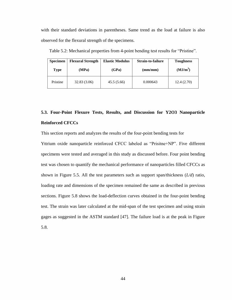
Table 5.2: Mechanical properties from 4-point bending test results for “Pristine”.
Specimen
Type
Flexural Strength
(MPa)
Elastic Modulus
(GPa)
Strain-to-failure
(mm/mm)
Toughness
(MJ/m3)
Pristine 32.83 (3.06) 45.5 (5.66) 0.000643 12.4 (2.70)
5.3. Four-Point Flexure Tests, Results, and Discussion for Y2O3 Nanoparticle
Reinforced CFCCs
This section reports and analyzes the results of the four-point bending tests for
Yttrium oxide nanoparticle reinforced CFCC labeled as “Prisitne+NP”. Five different
specimens were tested and averaged in this study as discussed before. Four point bending
test was chosen to quantify the mechanical performance of nanoparticles filled CFCCs as
shown in Figure 5.5. All the test parameters such as support span/thickness (L/d) ratio,
loading rate and dimensions of the specimen remained the same as described in previous
sections. Figure 5.8 shows the load-deflection curves obtained in the four-point bending
test. The strain was later calculated at the mid-span of the test specimen and using strain
gages as suggested in the ASTM standard [47]. The failure load is at the peak in Figure
5.8.
45
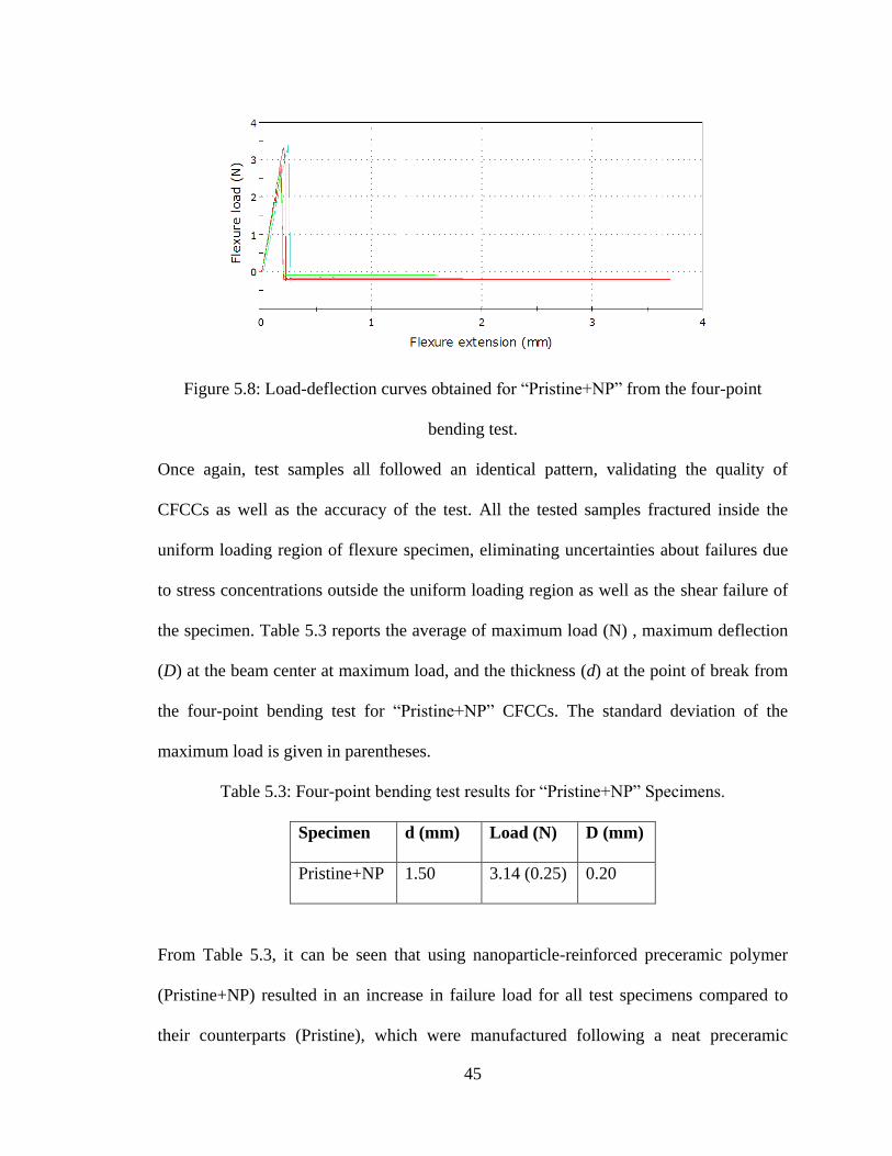
Figure 5.8: Load-deflection curves obtained for “Pristine+NP” from the four-point
bending test.
Once again, test samples all followed an identical pattern, validating the quality of
CFCCs as well as the accuracy of the test. All the tested samples fractured inside the
uniform loading region of flexure specimen, eliminating uncertainties about failures due
to stress concentrations outside the uniform loading region as well as the shear failure of
the specimen. Table 5.3 reports the average of maximum load (N) , maximum deflection
(D) at the beam center at maximum load, and the thickness (d) at the point of break from
the four-point bending test for “Pristine+NP” CFCCs. The standard deviation of the
maximum load is given in parentheses.
Table 5.3: Four-point bending test results for “Pristine+NP” Specimens.
Specimen d (mm) Load (N) D (mm)
Pristine+NP 1.50 3.14 (0.25) 0.20
From Table 5.3, it can be seen that using nanoparticle-reinforced preceramic polymer
(Pristine+NP) resulted in an increase in failure load for all test specimens compared to
their counterparts (Pristine), which were manufactured following a neat preceramic
46
polymer reinfiltration/pyrolysis cycle. On the other hand, due to solid state influence of
the nanoparticles, deflection of the specimens were slightly lowered for “Pristine+NP”
CFCCs.
Using Equations (1) thru (4), the flexural strength, modulus, strain to failure, and
toughness, respectively, for all five samples tested were calculated, averaged, and
reported in Table 5.4 with their standard deviations in the parentheses.
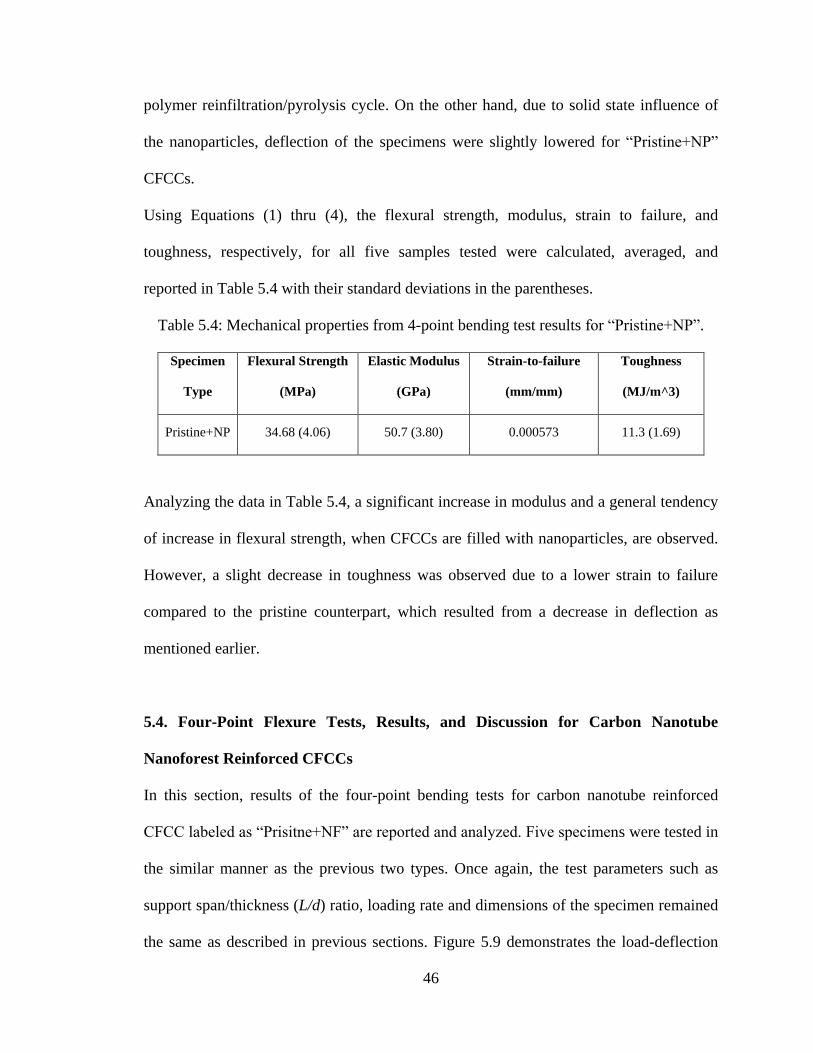
Table 5.4: Mechanical properties from 4-point bending test results for “Pristine+NP”.
Specimen
Type
Flexural Strength
(MPa)
Elastic Modulus
(GPa)
Strain-to-failure
(mm/mm)
Toughness
(MJ/m^3)
Pristine+NP 34.68 (4.06) 50.7 (3.80) 0.000573 11.3 (1.69)
Analyzing the data in Table 5.4, a significant increase in modulus and a general tendency
of increase in flexural strength, when CFCCs are filled with nanoparticles, are observed.
However, a slight decrease in toughness was observed due to a lower strain to failure
compared to the pristine counterpart, which resulted from a decrease in deflection as
mentioned earlier.
5.4. Four-Point Flexure Tests, Results, and Discussion for Carbon Nanotube
Nanoforest Reinforced CFCCs
In this section, results of the four-point bending tests for carbon nanotube reinforced
CFCC labeled as “Prisitne+NF” are reported and analyzed. Five specimens were tested in
the similar manner as the previous two types. Once again, the test parameters such as
support span/thickness (L/d) ratio, loading rate and dimensions of the specimen remained
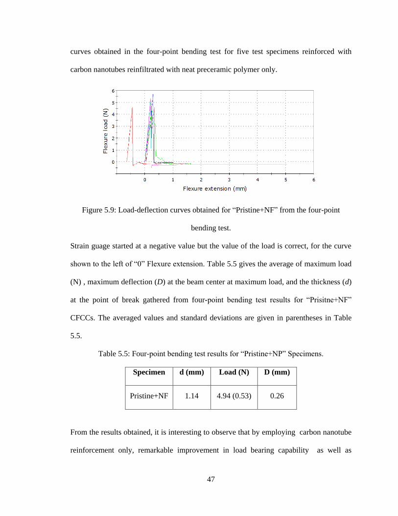
the same as described in previous sections. Figure 5.9 demonstrates the load-deflection
47
curves obtained in the four-point bending test for five test specimens reinforced with
carbon nanotubes reinfiltrated with neat preceramic polymer only.
Figure 5.9: Load-deflection curves obtained for “Pristine+NF” from the four-point
bending test.
Strain guage started at a negative value but the value of the load is correct, for the curve
shown to the left of “0” Flexure extension. Table 5.5 gives the average of maximum load
(N) , maximum deflection (D) at the beam center at maximum load, and the thickness (d)
at the point of break gathered from four-point bending test results for “Prisitne+NF”
CFCCs. The averaged values and standard deviations are given in parentheses in Table
5.5.
Table 5.5: Four-point bending test results for “Pristine+NP” Specimens.
Specimen d (mm) Load (N) D (mm)
Pristine+NF 1.14 4.94 (0.53) 0.26
From the results obtained, it is interesting to observe that by employing carbon nanotube
reinforcement only, remarkable improvement in load bearing capability as well as
48
deflection-to-failure of the CFCCs can be achieved. Equations (1) thru (4) were used to
calculate the mechanical properties of the carbon nanotube reinforced CFCCs in a similar
fashion as the previous two cases described above. Averaged properties are reported in
Table 5.6 below with standard deviations in the parentheses.
Table 5.6: Mechanical properties from 4-point bending test results for “Pristine+NF”
specimens.
The substantial increase in load bearing capability resulted in a substantial increase in
flexural strength, strain to failure, and subsequently an increase in toughness.
5.5. Four-Point Flexure Tests, Results, and Discussion for Y2O3 Nanoparticles and
Carbon Nanotube Nanoforest Reinforced CFCCs
In this section, the combination of yttrium oxide nanoparticles and carbon nanotube
reinforcements labeled as “Pristine+NP+NF” are analyzed and discussed. Five specimens
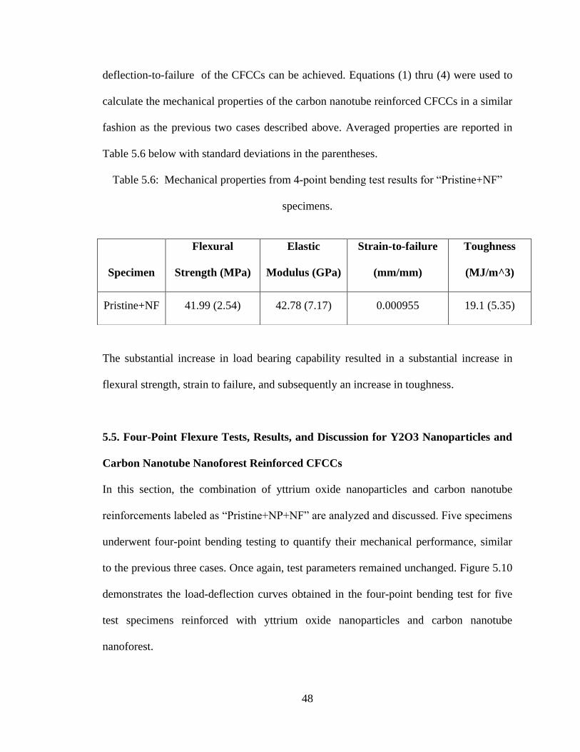
underwent four-point bending testing to quantify their mechanical performance, similar
to the previous three cases. Once again, test parameters remained unchanged. Figure 5.10
demonstrates the load-deflection curves obtained in the four-point bending test for five
test specimens reinforced with yttrium oxide nanoparticles and carbon nanotube
nanoforest.
Specimen
Flexural
Strength (MPa)
Elastic
Modulus (GPa)
Strain-to-failure
(mm/mm)
Toughness
(MJ/m^3)
Pristine+NF 41.99 (2.54) 42.78 (7.17) 0.000955 19.1 (5.35)
49
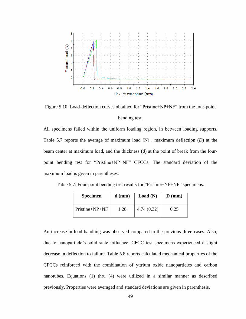
Figure 5.10: Load-deflection curves obtained for “Pristine+NP+NF” from the four-point
bending test.
All specimens failed within the uniform loading region, in between loading supports.
Table 5.7 reports the average of maximum load (N) , maximum deflection (D) at the
beam center at maximum load, and the thickness (d) at the point of break from the four-
point bending test for “Pristine+NP+NF” CFCCs. The standard deviation of the
maximum load is given in parentheses.
Table 5.7: Four-point bending test results for “Pristine+NP+NF” specimens.
Specimen d (mm) Load (N) D (mm)
Pristine+NP+NF 1.28 4.74 (0.32) 0.25
An increase in load handling was observed compared to the previous three cases. Also,
due to nanoparticle’s solid state influence, CFCC test specimens experienced a slight
decrease in deflection to failure. Table 5.8 reports calculated mechanical properties of the
CFCCs reinforced with the combination of yttrium oxide nanoparticles and carbon
nanotubes. Equations (1) thru (4) were utilized in a similar manner as described
previously. Properties were averaged and standard deviations are given in parenthesis.
50
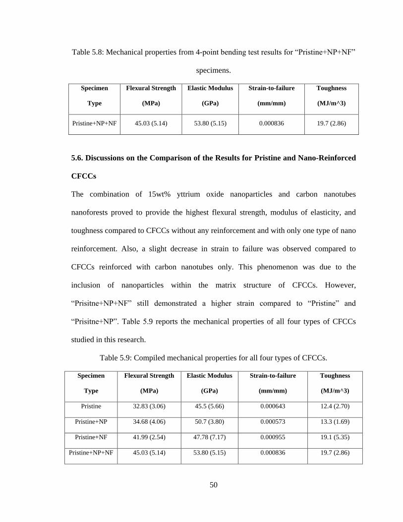
Table 5.8: Mechanical properties from 4-point bending test results for “Pristine+NP+NF”
specimens.
Specimen
Type
Flexural Strength
(MPa)
Elastic Modulus
(GPa)
Strain-to-failure
(mm/mm)
Toughness
(MJ/m^3)
Pristine+NP+NF 45.03 (5.14) 53.80 (5.15) 0.000836 19.7 (2.86)
5.6. Discussions on the Comparison of the Results for Pristine and Nano-Reinforced
CFCCs
The combination of 15wt% yttrium oxide nanoparticles and carbon nanotubes
nanoforests proved to provide the highest flexural strength, modulus of elasticity, and
toughness compared to CFCCs without any reinforcement and with only one type of nano
reinforcement. Also, a slight decrease in strain to failure was observed compared to
CFCCs reinforced with carbon nanotubes only. This phenomenon was due to the
inclusion of nanoparticles within the matrix structure of CFCCs. However,
“Prisitne+NP+NF” still demonstrated a higher strain compared to “Pristine” and
“Prisitne+NP”. Table 5.9 reports the mechanical properties of all four types of CFCCs
studied in this research.
Table 5.9: Compiled mechanical properties for all four types of CFCCs.
Specimen
Type
Flexural Strength
(MPa)
Elastic Modulus
(GPa)
Strain-to-failure
(mm/mm)
Toughness
(MJ/m^3)
Pristine 32.83 (3.06) 45.5 (5.66) 0.000643 12.4 (2.70)
Pristine+NP 34.68 (4.06) 50.7 (3.80) 0.000573 13.3 (1.69)
Pristine+NF 41.99 (2.54) 47.78 (7.17) 0.000955 19.1 (5.35)
Pristine+NP+NF 45.03 (5.14) 53.80 (5.15) 0.000836 19.7 (2.86)
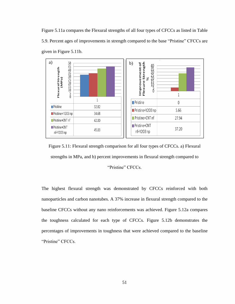
51
Figure 5.11a compares the Flexural strengths of all four types of CFCCs as listed in Table
5.9. Percent ages of improvements in strength compared to the base “Pristine” CFCCs are
given in Figure 5.11b.
Figure 5.11: Flexural strength comparison for all four types of CFCCs. a) Flexural
strengths in MPa, and b) percent improvements in flexural strength compared to
“Pristine” CFCCs.
The highest flexural strength was demonstrated by CFCCs reinforced with both
nanoparticles and carbon nanotubes. A 37% increase in flexural strength compared to the
baseline CFCCs without any nano reinforcements was achieved. Figure 5.12a compares
the toughness calculated for each type of CFCCs. Figure 5.12b demonstrates the
percentages of improvements in toughness that were achieved compared to the baseline
“Pristine” CFCCs.
a) b)
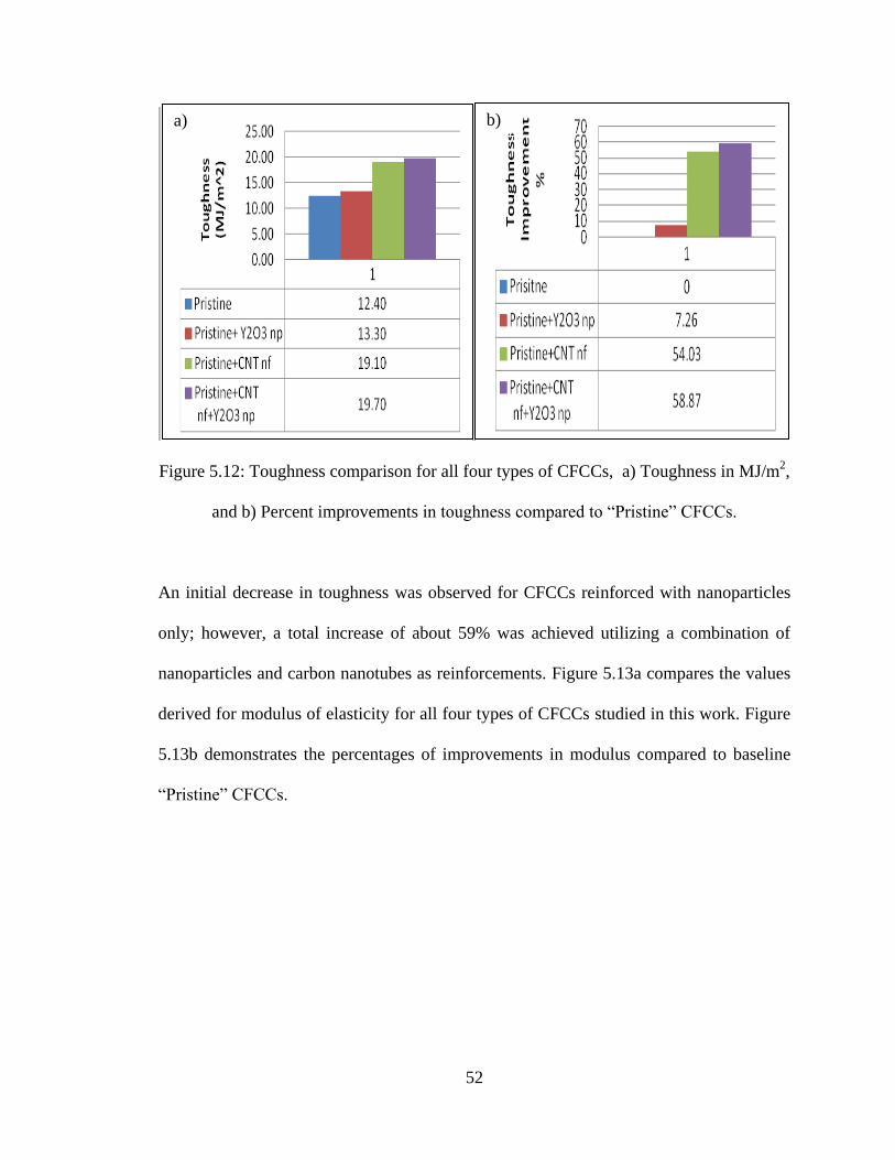
52
Figure 5.12: Toughness comparison for all four types of CFCCs, a) Toughness in MJ/m2,
and b) Percent improvements in toughness compared to “Pristine” CFCCs.
An initial decrease in toughness was observed for CFCCs reinforced with nanoparticles
only; however, a total increase of about 59% was achieved utilizing a combination of
nanoparticles and carbon nanotubes as reinforcements. Figure 5.13a compares the values
derived for modulus of elasticity for all four types of CFCCs studied in this work. Figure
5.13b demonstrates the percentages of improvements in modulus compared to baseline
“Pristine” CFCCs.
a) b)
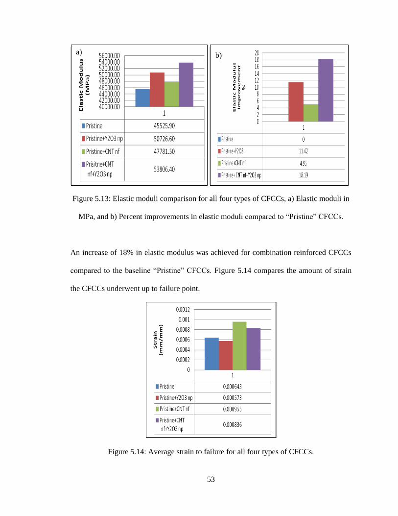
53
Figure 5.13: Elastic moduli comparison for all four types of CFCCs, a) Elastic moduli in
MPa, and b) Percent improvements in elastic moduli compared to “Pristine” CFCCs.
An increase of 18% in elastic modulus was achieved for combination reinforced CFCCs
compared to the baseline “Pristine” CFCCs. Figure 5.14 compares the amount of strain
the CFCCs underwent up to failure point.
Figure 5.14: Average strain to failure for all four types of CFCCs.
a) b)
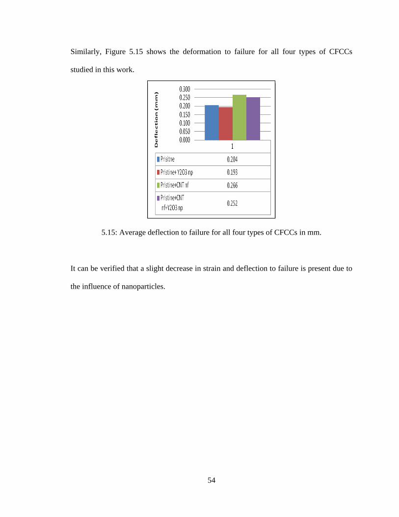
54
Similarly, Figure 5.15 shows the deformation to failure for all four types of CFCCs
studied in this work.
5.15: Average deflection to failure for all four types of CFCCs in mm.
It can be verified that a slight decrease in strain and deflection to failure is present due to
the influence of nanoparticles.
55
CHAPTER 6
CONCLUSIONS AND FUTURE WORK
6.1. Conclusions
Four different systems of continuous fiber ceramic composites (CFCCs), (i.e., Pristine,
Pristine+NP, Pristine+NF, Pritine+NP+NF), are manufactured, following preceramic
polymer pyrolysis (PIP) route. In this study, effects of different nano-materials on the
flexural mechanical properties of continuous fiber ceramic composites (CFCCs) are
experimentally investigated. Five different sets of CFCC specimens are manufactured
and tested. Woven Silicon Carbide (Nicalon™) ceramic fabric is used here. Preceramic
polymer (KiON CERASET®
) is used as the base matrix in the current study. A
characterization analysis of the samples using scanning electron microscopy reveales
excellent quality of the manufactured parts. High carbon nanotube growth on ceramic
fabric and good dispersion of yttrium oxide nanoparticles in matrix are obtained for all
sets of samples, leading to excellent quality of the manufactured parts. Four-point
bending test, based on ASTM C1341 standard, is conducted to evaluate the mechanical
performance of the ceramic composite samples at room temperature. All the tested
samples fractured inside the uniformly stressed region of flexure specimen (i.e., between
the inner loading points of the fixture).
Initially continuous fiber ceramic composites without any reinforcements are
manufactured. For these sets of samples named “Pristine”, neat preceramic polymer is
used for all reinfiltration/pyrolysis cycles. Samples were then tested. After the initial
results, three types of nano reinforced CFCCs (nanocomposites) are manufactured to be
56
compared with baseline “Pristine” CFCC. “Pristine+NP” depicts CFCC reinforced with
15wt% yttrium oxide nanoparticles, “Pristine+NF” depicts CFCC reinforced with carbon
nanotube nanoforest, and consequently, “Pristine+NP+NF” depicts CFCCs reinforced
with a combination of 15wt% yttrium oxide nanoparticles and carbon nanotube
nanoforest. Nanoparticles (i.e., yttrium oxide) used in this work, varied in size from 15-
55 nanometers. Carbon nanotubes employed in this study had lengths in the range of 30-
50 nanometers. Plain weave ceramic fiber reinforcements (Nicalon™) woven fabric is
used here. Preceramic polymer (KiON CERASET®
) is mixed with the nano size particles
in the presence of a surfactant agent to give a good dispersion of the particles during the
process and is used as the matrix. A characterization analysis of the samples using
scanning electron microscopy revealed excellent quality of the parts. In general, the
weight gain percentage at each stage of reinfiltration/pyrolysis for both types of
nanoparticle filled ceramic nanocomposites is consistently less than that for ceramic
composites manufactured without nanoparticles. This shows the compactness of the
nanocomposites. Four-point bending test is conducted to evaluate the flexural mechanical
performance of the nano ceramic composite samples at room temperature. All the tested
samples fractured inside the uniform loading region of flexure specimen (i.e., between
the inner loading points of the fixture). As a result, CFCCs reinforced with a combination
of nanoparticles and carbon nanotubes had the highest performance such as over 45%
improvement in flexural strength, about 60% improvement in toughness, and over 18%
improvement in modulus of elasticity compared to the baseline “Pristine” CFCC,
achieved in this work.
57
Further, experimental results concluded that CFCCs reinforced with a combination of
nanoparticles and carbon nanotubes, show consistently better flexural strength as well as
toughness compared to their unreinforced CFCC counterpart. This result is a major
breakthrough in the research area of 3D ceramic composites.
6.2. Future Work
There are a number of studies related to this work that are subject of future studies. For
example, the structural (e.g., bending and tension) and non-structural (e.g., thermal, etc.)
performances of the pristine and nano-reinforced materials should be evaluated at higher
temperatures of 1500 to 1600 oC. In addition, it is important to evaluate the performances
of various preceramic polymers at room - and high – temperatures for their pristine and
nano-reinforced materials cases, and study the effects of pyrolysis temperatures of 1000
oC and 1500-1600
oC for the above-mentioned cases.
Finally, the characterization studies (e.g., SEM, TEM, etc.) should be conducted on the
specimens during the preparation and as-manufactured specimens (for the study of the
nanoparticle and carbon nanotube bondings to the matrix) as well as the fracture surfaces
of the mechanically tested specimens to provide insights, in the quality control as well as
fracture mechanisms of these advanced Continuous Fiber Ceramic Nano-composites
(CFCNs).
58
REFERENCES
1. Mecholsky, Jr., J.J., “Engineering Research Needs of Advanced Ceramics and
Ceramic-Matrix Composites”, Ceramic Bulletin, 1989;68(2):367-375.
2.Marthur Sanjay “Mechanical Behavior and Performance of Ceramics and
Composites”, 36th
International Conference & Exposition on Advanced Ceramics
& Composites, 2012
3. Prewo, M. K., J. J. Brennan and G. K. Layden "Fiber-reinforced Glasses and
Glass-Ceramics for High Performance Applications," American Ceramic Society
Bulletin, 1986;65(2):305-322.
4. Hench, L. L. and D. R. Ulrich “Ultra-structure Processing of Ceramics, Glasses
and Composites” New York, NY, John Wiley Publishing Co., 1984.
5. Rolls-Royce LLC, http://www.rolls-
royce.com/technology_innovation/material_tech/composites.jsp , 2012.
6. Chawla, N., Chawla, K.K., Koopman, M., Patel, B., Coffin, C., Eldridge, J.I. "
Thermal-Shock Behavior of a Nicalon-Fber-Feinforced Hybrid Glass-Ceramic
Composite ", Composites Science and Technology, 61 (2001) 1923-1930.
7. Strife, J.R., J.J. Brennan, and K.M. Prewo, “Status of Continuous Fiber-
Reinforced Ceramic Matrix Composite Processing Technology”, Ceram. Eng. Sci.
Proc., 1990;11(7-8):871-919.
8. Ustundag E., Fischman G.," Fabrication of High Performance SiC/SiC Composite by
Polymer Impregnation and Pyrolysis Method," American Ceramic Society
Bulletin, 1999; vol. 20, issue 4.
59
9. Baldus P., Jansen M., Sporn D.," Ceramic Fibers for Matrix Composites in High-
Temperature Engine Applications”, Science journal, 199, vol. 285, no. 5428, 699-
703
10. Kotani, M., Inoue T., Kohyama, A., Okamua K., Katch Y.," Consolidation
of polymer-derived SiC matrix composites: processing and microstructure”,
Composite Science and Technology, 2002, 62 (16), 2179-2188
11. Rogers, J J., J. Semen, and Y.-F. Yu "Silicon Carbide and Silicon Nitride
Structural Ceramics Derived from a Preceramic Polymer Binder," Ceram. Eng.
Sci. Proc., 1989;10(7-8):833-836.
12. Semen, J. and J. G. Loop "Structural Ceramics Derived from a Preceramic
Polymer," Ceram. Eng. Sci. Proc., 1990;11(9-10):1387-1394.
13. Semen, J. and J. G. Loop "A Preceramic Polymer Route to Molded SiC Ceramic
Parts," Proceedings of Ceramic Engineering and Science, 1991;12(9-10):1967-
1980.
14. Hurwitz, F. I., P. J. Heimann, J. Z. Gyekenyesi, J. Masnovi and X-Y. Bu
"Polymeric Routes to Silicon Carbide and Silicon Oxycarbide CMC,"
Proceedings of Ceramic Engineering and Science, 1991;12(7-8):1292-1303.
15. Rice, R. W., W. J. McDonough, G. Y. Richardson, J. M. Kunetz and T. Schroeter
"Ceramics from Polymer Pyrolysis, Opportunities and Needs - A Materials
Perspective," American Ceramics Society Bulletin, 1983;62(8):889- 892.
16. Cornie A. J, C Yet-ming, D. R. Uhlmann, R. D, Mortensen and M. J. Collins
"Processing of Metal and Ceramic Matrix Composites," American Ceramic
Society Bulletin, 1986;65(2):293-304.
60
17. Ghasemi-Nejhad, M. N., Chandramouli, M. V., and Yousefpur, A. “Processing
and performance of Continuous Fiber Ceramic Composites by Preceramic
Polymer Pyrolysis: I – Filament Winding,” Journal of Composite Materials,
2001;35(24):2207-2237.
18. Ghasemi-Nejhad, M. N., Bayliss, J. K., and Yousefpur, A. “Processing and
performance of Continuous Fiber Ceramic Composites by Preceramic Polymer
Pyrolysis: II – Resin Transfer Molding,” Journal of Composite Materials,
2001;35(24): 2239-2255.
19. Kochendorfer, R. "Liquid Silicon Infiltration - A Fast and Low Cost CMC -
Manufacturing Process," Proceedings of 8th International Conference on
Composite Materials, ICCM/VIII, Composites-Design, Manufacture, and
Application, S.W. Tsai and G.S. Springer, Eds., Honolulu, HI, 1999;22-29:
23.F.1-23.F.9.
20. Riccitiello, S. and. Marshall, K. M. "3-D Ceramic Matrix Composite
Development," Journal of Advanced Materials, 1994; 25(2):22 -28.
21. Tai N-H. "Modeling of Chemical Vapor Infiltration (CVI) in Ceramic Matrix
Composites Processing," Ph. D. Dissertation, Department of Mechanical
Engineering, University of Delaware, Newark, DE, 1990.
22. Kim, Y-W., Song, J-S., Park S-W., and. Lee J-G. "Nicalon Fiber-Reinforced
Silicon-Carbide Composites via Polymer Solution Infiltration and Chemical
Vapour Infiltration," Journal of Material Science, 1993;28:3866-3868.
61
23. Hurwitz, F. I., Gyekenyesi, J. Z.,. Conroy, J. P "Polymer Derived Nicalon/Si-C-O
Composites: Processing and Mechanical Behavior," Ceram. Eng. Sci. Proc, 1989;
10(7-8):750-763.
24. Toreki, W., Batich, D. C., Sacks, D. M., and Morrone, A. A. "Synthesis and
Application of a Vinylsilazane Preceramic Polymer," Ceram. Eng. Sci. Proc.,
1990;11(9-10):1371-1386.
25. Liu, H.-K and. Parvizi-Majidi, A. "The effect of Solid particle Addition in Sol-Gel
Processing of Ceramic Matrix Composites," Ceram. Eng. Sci. Proc., 1992;13(9-
10):642-649.
26. Liu, H.-K and A. Parvizi-Majidi "Drying of Sol-Gel Processed 3-D Ceramic
Matrix Composites, " Proceedings of the HT-CMC 93 Symposium of the
European Association for Composite Materials Conference, 1993.
27. Yousefpour, A. and Ghasemi-Nejhad, M. N. “Processing and Performance of
Nicalon/Blackglas and Nextel/Blackglas using cure-on-the-fly filament winding
and preceramic polymer pyrolysis with inactive fillers”, Composites Science and
Technology, 2001;61(13):1813-1820.
28. Ajayan, P. M.. Schadler, L. S., and. Braun, P. V. Nanocomposite Science and
Technology, Wiley-VCH, Weinheim, 2003.
29. Thostenson, E. T., C. Li, T. W. Chou, “Nanocomposites in Context”, Composites
Sci. and Tech., 2005;65:491-516.
30. Ghasemi Nejhad, M.N., Veedu, V.P., Yuen, A., and Askari, D., “Polymer Matrix
Composites with Nanoscale Reinforcements,” US Patent Number
62
7,658,870, February 9, 2010, and US Patent Number 7,875,212 B2, January
25, 2011
31. Wetzel, B., F. Haupert, and M. Q. Zhang, “Epoxy nanocomposites with high
mechanical and tribological performance,” Comp. Sci. and Tech., 2003;63:2055-
2067.
32 Veedu, V. P., Cao, A., Li, X., Ma, K., Soldano, C., Ajayan, P. M., and Ghasemi-
Nejhad, M. N., " Multifunctional composites using reinforced laminae with
carbon nanotube forests," Nature Materials, June 2006, Vol. 5, pp. 457-462..
33. Ghasemi Nejhad, M.N., Veedu, V.P., Cao, A., Ajayan. P. M., and Askari, D., “Three-
Dimensionally Reinforced Multifunctional Nanocomposites,” World-
wide/International Patent Applications, European Patent Issued on September
30, 2009; EP 1 966 286 B1; US Patent Issued on April 3, 2012, U.S. Patent No.
8,148,276 B2; Chinese Patent Issued on April 24, 2012, Chinese Patent No.
200680051863.5.
34. Wang, S., Wang, M., Lei, Y., and Zhang, L., “ ‘Anchor effect’ in poly(styrene
maleic anhydride)/TiO2 nanocomposites”, Journal of Materials Science Letters,
1999;18(24):2009-2012.
35. Caris, C., van Elven, L., van Herk, A., and German, A., “Polymerization of MMA
(methyl methacrylate) at the surface of inorganic submicron particles”, British
Polymer Journal, 1989;21(2):133-40.
36. Veedu, V. P., Ghasemi-Nejhad, M. N., Gudapati, V. M. “Preceramic precursor
pyrolysis for flexural property evaluation of continuous fiber ceramic
nanocomposites with nanoparticles”, Composites Sci. and Tech, 2005 (in press).
63
37. Veedu, V. P.,Cao, A., Ghasemi-Nejhad, M.N., Gudapati, V. M. “Weight
Fraction Effects of Nanoparticle Inclusion on Mechanical Performance of
Continuous Fiber Ceramic Composites”, Proc. 6th Pacific Rim Conf. on Ceramic
& Glass Tech., September 2005, Maui, Hawaii.
38. Tai, N. H., M. K. Yeh, J. H. Liu, “Enhancement of the Mechanical Properties of
Carbon Nanotube/Phenolic Composites Using a Carbon Nanotube Network as the
Reinforcement”, Carbon, 2004;42:774–7.
39. Hussain, M., Nakahara, A., Nishijima, S., and Niihara, K. “Fracture behavior and
fracture toughness of particulate filled epoxy composites”, Materials Letters,
1996;27(1,2):21-25.
40. Mazumdar S.K., Composites Manufacturing:Materials, Product,and Process
Engineering, CRC Press, 2003.
41. Ng, C. B., L. S. Schadler, and R. W. Siegel, “Synthesis and mechanical properties of
TiO2-epoxy nanocomposites,” Nanostructured Mater, 1999;12:507–510.
42. Gudapati, V. M., Veedu, V. P., Cao, A., and Ghasemi Nejhad, M. N., “Experimental
Investigation of Optimal Nanoparticle Inclusion for Enhanced Flexural
Performance in Continuous Fiber Ceramic Nanocomposites,” Journal of
Thermoplastic Composite Materials, Vol. 22, No. 4, 2009, pp. 421-438.
43. Product Data Sheet KiON CERASET® Polyureasilazane, KiON Corporation,
Huntingdon Valley, PA, U.S.A., 2004.
44. Material Safety Data sheet, BASF Corporation – Performance Chemicals, Mount
Olive, NJ, 2004.
45. Dow Corning Corporation. Information about NicalonTM ceramic fiber, 2001.
64
46. Product Specification Sheet, Sigma-ALDRICH, Inc., St. Louis, MO, 2004.
47. ASTM standard: C1341-97, Standard Test Method for Flexural Properties of
Continuous Fiber-Reinforced Advanced Ceramic Composites, 2004;15.01: 509-
526.
48. Pelican®
1200 case with no Foam – Black, www.pelican-case.com/1200.html, 2011.