Embed Size (px)
Citation preview
Applications of Programmable Logic
Controllers
DG31 34
Purpose
• Unit purpose:• This Unit is designed to introduce candidates to
Programmable Logic Controllers (PLCs) and enablethem to understand how PLCs are applied to controlindustrial processes.
• The Unit allows candidates to develop the necessaryknowledge and skills to allow them to understand thebasic construction and operation of PLCs.
• The Unit also provides candidates with the opportunity todevelop practical programming skills to enable them toapply a PLC to simulate control of a specified industrialprocess.
Learning Outcomes
1. Explain and classify PLC hardware.2. Describe the operation of PLC
software. 3. Solve an industrial related control
problem by the safe application of PLC technology.
Assessment - 1
• The assessment for Outcomes 1 and 2 inthis Unit should be combined together intoone written assessment paper.
• This paper should be taken by candidatesat one single assessment event thatshould last one hour and thirty minutes.
• This assessment should be conductedunder controlled, supervised conditions.
Assessment - 2
• Outcome 3 should be assessed by anassignment in which candidates are asked tocomplete a series of tasks to enable them toapply a PLC to simulate the safe control of aspecified industrial process.
• The assignment tasks should involve devisingthe control strategy, writing PLC software,programming of the PLC, verifying correctoperation of the program and documentation ofthe final solution.
Assessment - 2
• Candidates should complete theassignment in eight hours.
• Candidates should have access to a PLCand be allowed to use any relevant coursenotes, textbooks and reference materialfor the PLC.
• Both the written assessment and thepractical assignment should be carried outat the end of the delivery of the Unit.

Programmable Logic Controller
What is a PLC
A Programmable Logic Controller (PLC) is a mini computer specifically designed for industrial use.
PLC Origin
Developed to replace relays in the late 1960s
Costs dropped and became popular by 1980s
Now used in many industrial designs
Purpose of PLC
• Pneumatic and Hydraulic Machines• Robots• Production Processes• Packaging Lines• Signalling Systems (Traffic Lights etc)• Refining Processes
Examples of PLC Applications are:
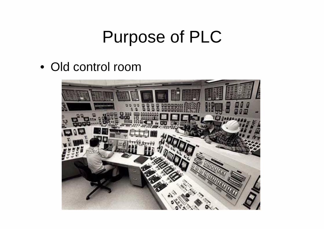
Purpose of PLC
• Old control room
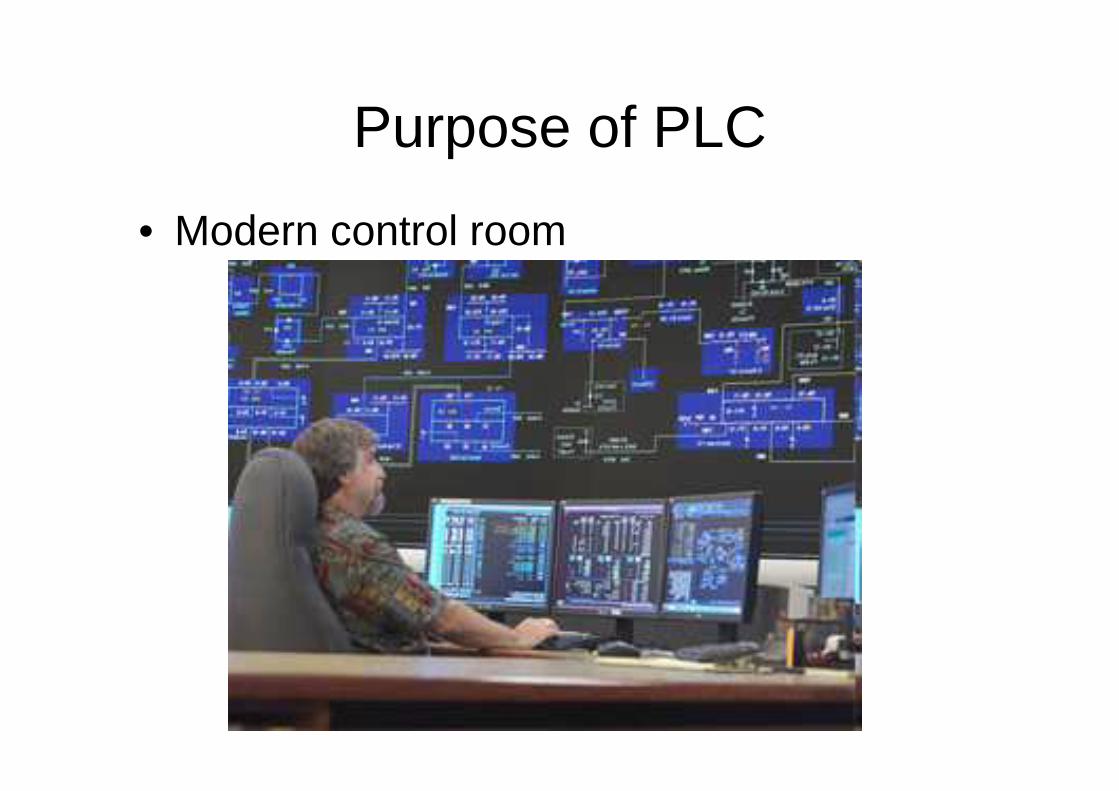
Purpose of PLC
• Modern control room
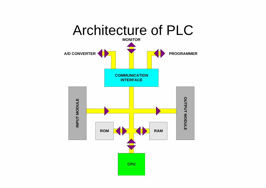
Architecture of PLC
COMMUNICATIONINTERFACE
OU
TP
UT
MO
DU
LEIN
PU
T M
OD
UL
E
ROM
CPU
RAM
MONITOR
PROGRAMMERA/D CONVERTER

Architecture of PLC
Classification of PLC’s
• Large• Medium • Small
PLCs are Classified by :•Number of Input / Output terminals
•Available Memory
•Into three categories
Classification of PLC’s
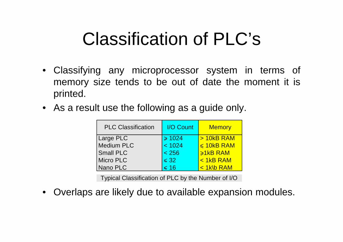
• Classifying any microprocessor system in terms ofmemory size tends to be out of date the moment it isprinted.
• As a result use the following as a guide only.
• Overlaps are likely due to available expansion modules.
PLC Classification I/O Count
Large PLC Medium PLC Small PLC Micro PLC Nano PLC
> 1024 < 1024 < 256 < 32 < 16
Typical Classification of PLC by the Number of I/O
Memory
> 10kB RAM < 10kB RAM >1kB RAM < 1kB RAM < 1k\b RAM
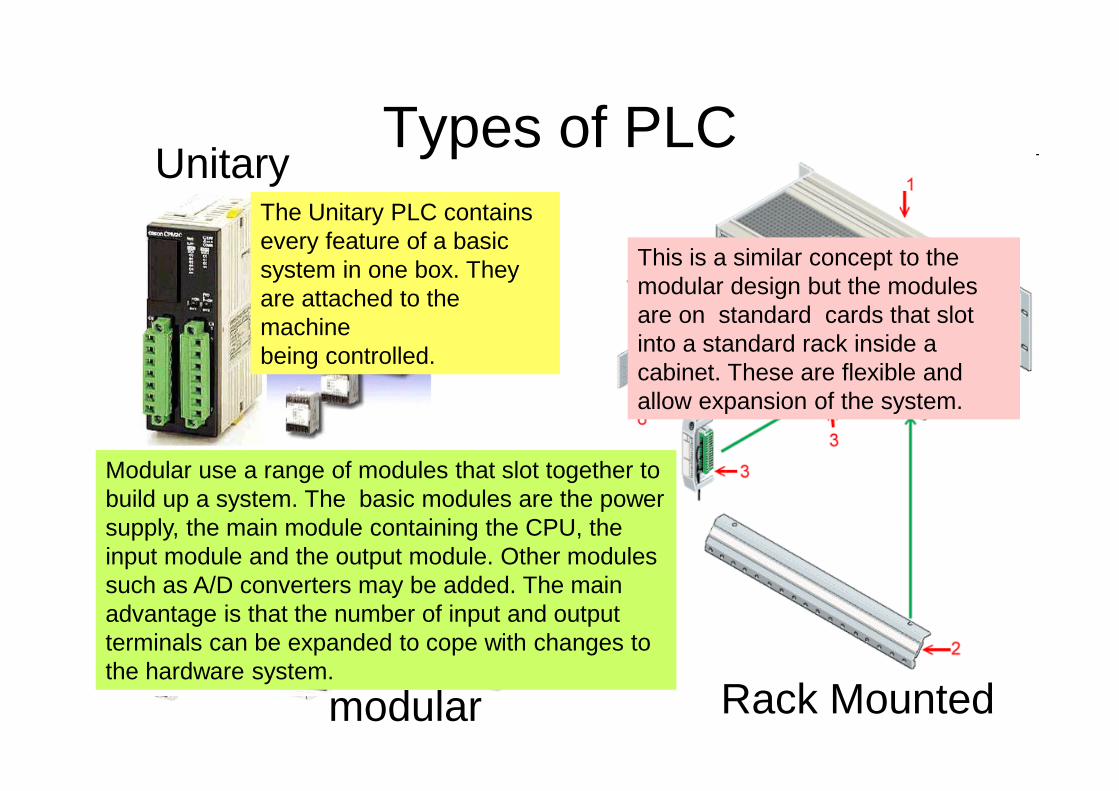
Types of PLCUnitary
modular Rack Mounted
The Unitary PLC contains every feature of a basic system in one box. They are attached to the machine being controlled.
Modular use a range of modules that slot together to build up a system. The basic modules are the power supply, the main module containing the CPU, the input module and the output module. Other modules such as A/D converters may be added. The main advantage is that the number of input and output terminals can be expanded to cope with changes to the hardware system.
This is a similar concept to the modular design but the modules are on standard cards that slot into a standard rack inside a cabinet. These are flexible and allow expansion of the system.
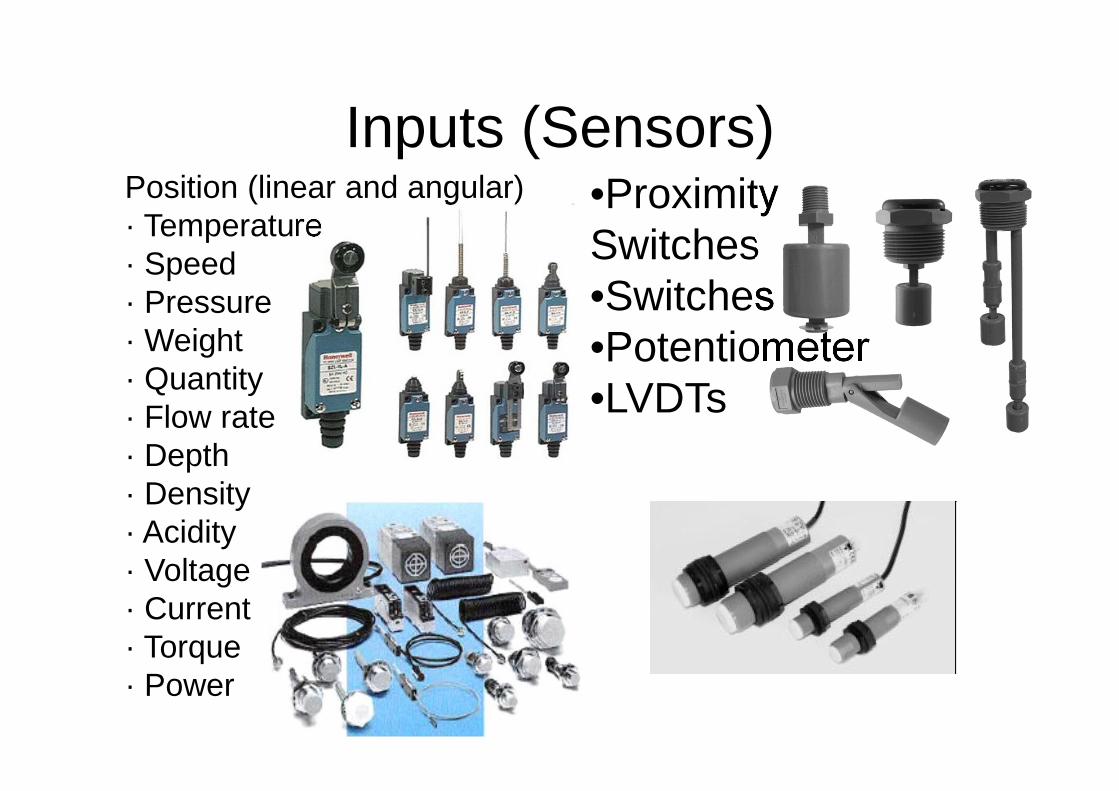
Inputs (Sensors)•Proximity Switches•Switches•Potentiometer•LVDTs
Position (linear and angular)· Temperature· Speed· Pressure· Weight· Quantity· Flow rate· Depth· Density· Acidity· Voltage· Current· Torque· Power
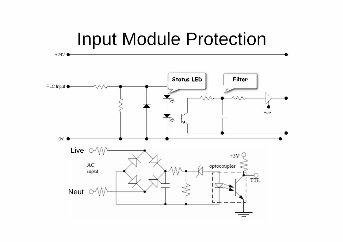
Input Module Protection
Live
Neut
Outputs (Actuators)
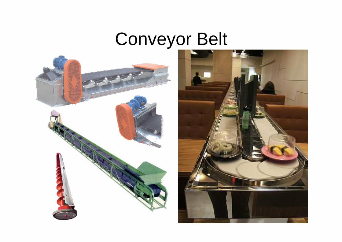
Conveyor Belt
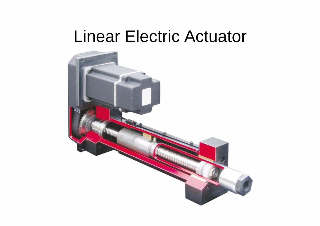
Linear Electric Actuator
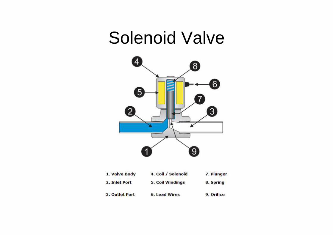
Solenoid Valve

Steam & High Pressure Solenoid Valves
High Pressure Steam Solenoid
Water Solenoid Valve
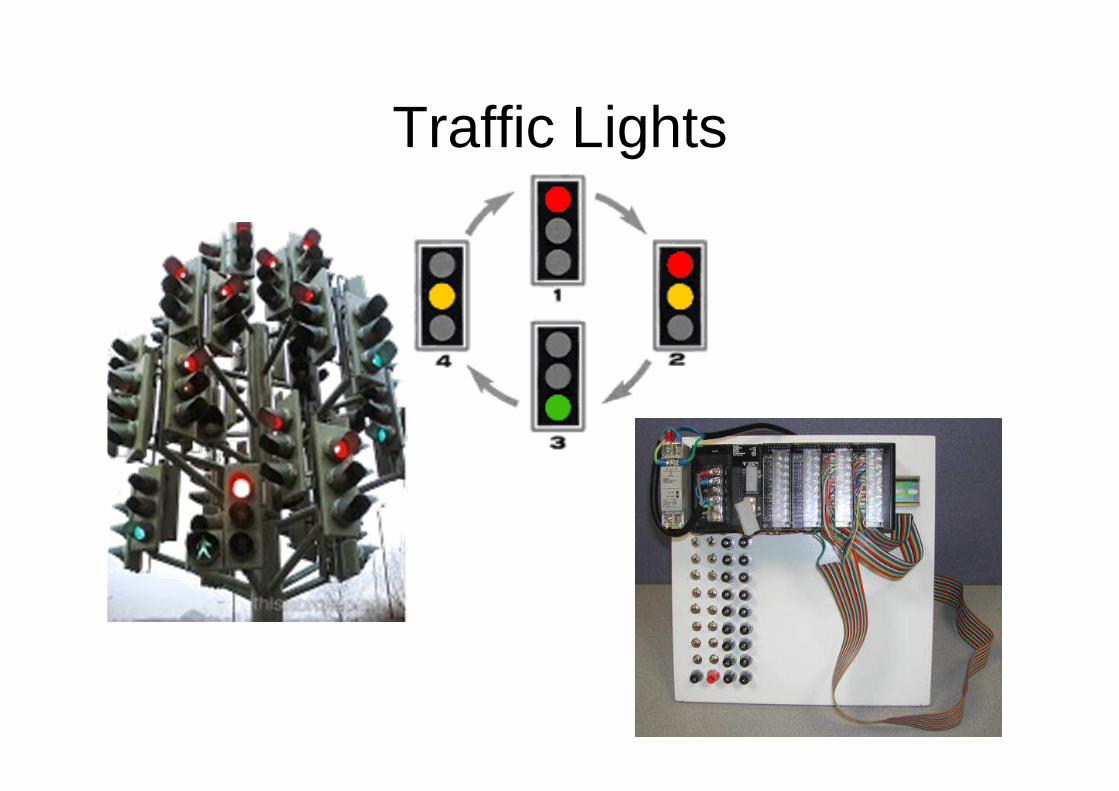
Traffic Lights
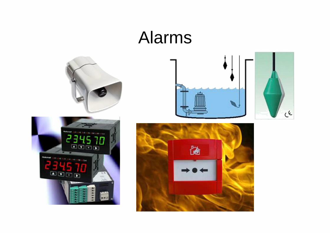
Alarms

Heating Elements
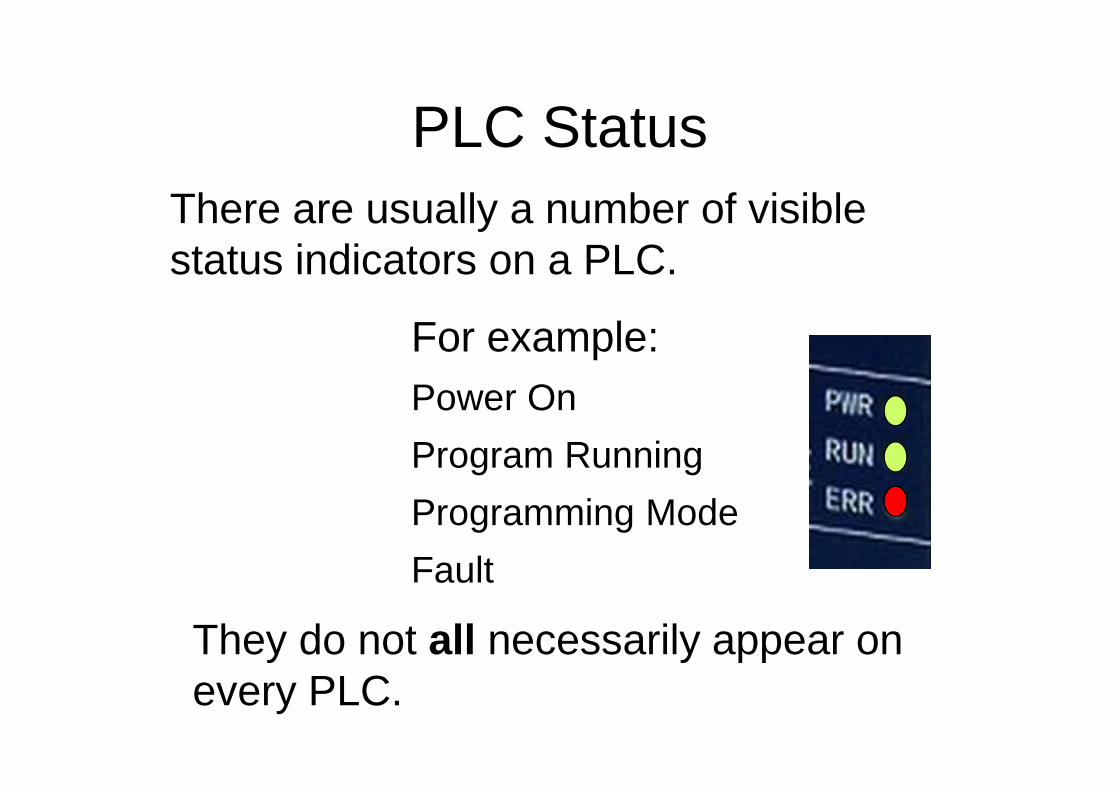
PLC Status
For example:Power On
Program Running
Programming Mode
Fault
There are usually a number of visible status indicators on a PLC.
They do not all necessarily appear on every PLC.
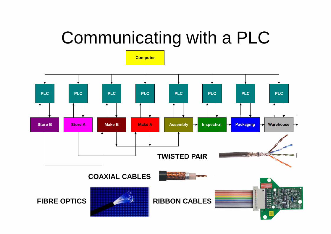
Communicating with a PLC
COAXIAL CABLES
TWISTED PAIR
FIBRE OPTICS
Computer
PLC PLCPLC PLCPLC PLCPLC PLC
Make AMake BStore AStore B Inspection PackagingAssembly Warehouse
RIBBON CABLES
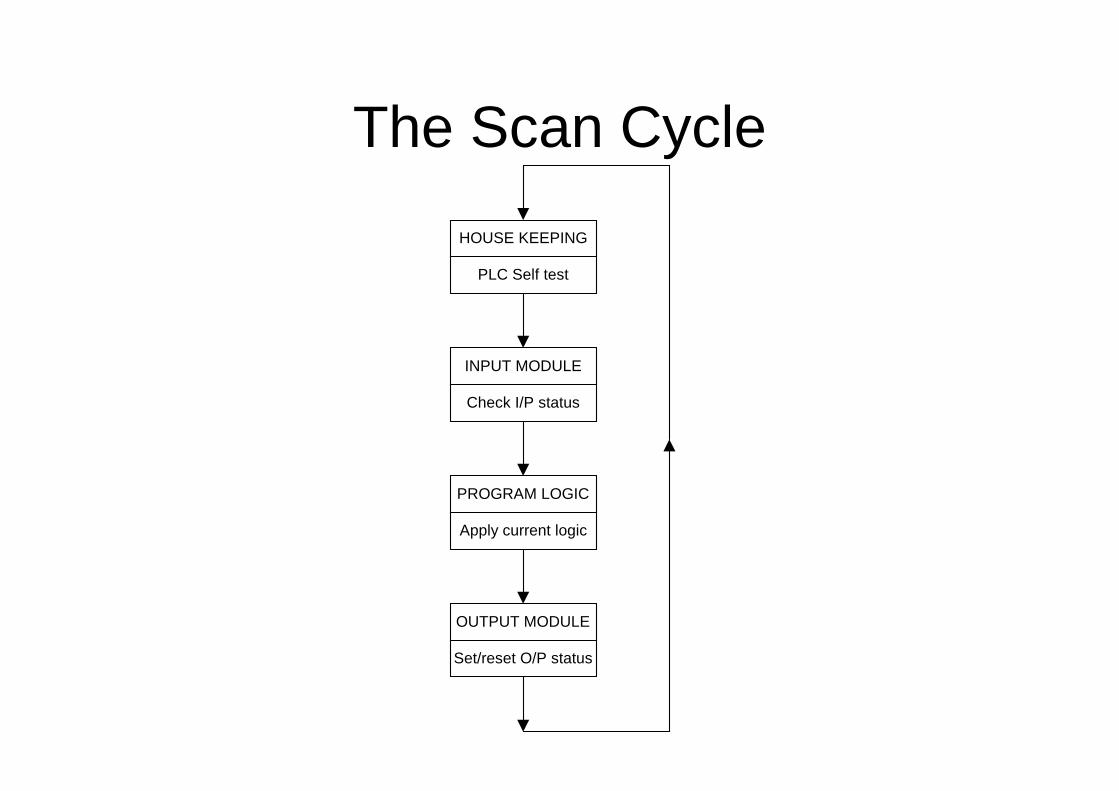
The Scan Cycle
HOUSE KEEPING
INPUT MODULE
PROGRAM LOGIC
OUTPUT MODULE
PLC Self test
Check I/P status
Apply current logic
Set/reset O/P status
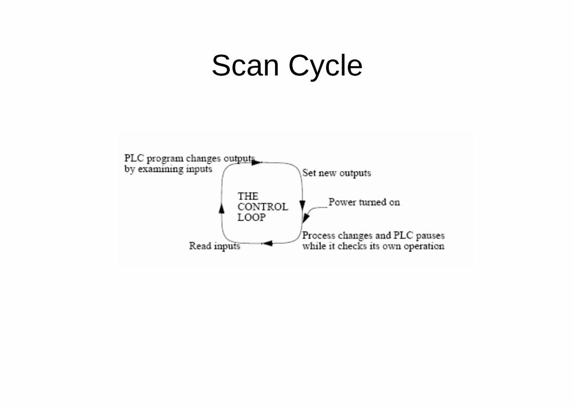
Scan Cycle
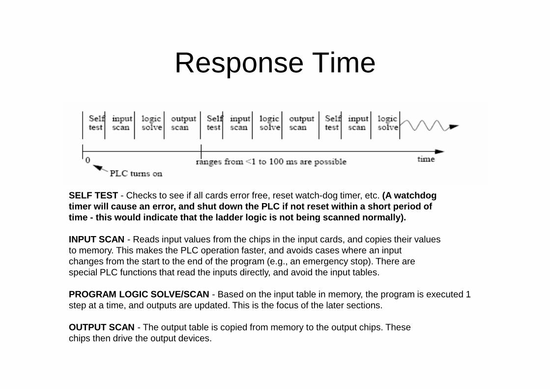
Response Time
SELF TEST - Checks to see if all cards error free, reset watch-dog timer, etc. (A watchdogtimer will cause an error, and shut down the PLC if not reset within a short period oftime - this would indicate that the ladder logic is not being scanned normally).
INPUT SCAN - Reads input values from the chips in the input cards, and copies their valuesto memory. This makes the PLC operation faster, and avoids cases where an inputchanges from the start to the end of the program (e.g., an emergency stop). There arespecial PLC functions that read the inputs directly, and avoid the input tables.
PROGRAM LOGIC SOLVE/SCAN - Based on the input table in memory, the program is executed 1step at a time, and outputs are updated. This is the focus of the later sections.
OUTPUT SCAN - The output table is copied from memory to the output chips. Thesechips then drive the output devices.

Any Questions
PLC Faults
The PLC has certain diagnostic, monitoring and testing facilities within the software.
On most PLC’s Light Emitting Diodes (LED’s) shows the status of the inputs and outputs, some show status by way of a Liquid Crystal Display (LCD).
It is also possible to fix a bank of switches to the input side and test a programme by setting the switches to a known states and seeing if the appropriate output action is taken.
The most advanced method - connects the PLC to a computer with appropriate software and runs a complete simulation of the system being controlled showing the status of everything.
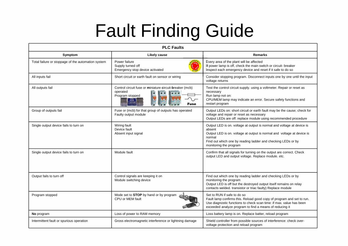
Fault Finding Guide
Shield controller from possible sources of interference: check over-voltage protection and reload program
Gross electromagnetic interference or lightning damageIntermittent fault or spurious operation
Loss battery lamp is on. Replace batter, reload program Loss of power to RAM memoryNo program
Set to RUN if safe to do so Fault lamp confirms this. Reload good copy of program and set to run. Use diagnostic functions to check scan time: if max. value has been exceeded analyze program to find a means of reducing it
Mode set to STOP by hand or by programCPU or MEM fault
Program stopped
Find out which one by reading ladder and checking LEDs or by monitoring the program Output LED is off but the destroyed output itself remains on relay contacts welded. transistor or triac faulty) Replace module
Control signals are keeping it on Module switching device
Output fails to turn off
Confirm that all signals for turning on the output are correct. Check output LED and output voltage. Replace module. etc.
Module faultSingle output device fails to turn on
Output LED is on. voltage at output is normal and voltage at device is absent Output LED is on. voltage at output is normal and voltage at device is normalFind out which one by reading ladder and checking LEDs or by monitoring the program
Wiring faultDevice faultAbsent input signal
Single output device fails to turn on
Output LEDs on: short circuit or earth fault may be the cause; check for voltage and repair or reset as necessaryOutput LEDs are off: replace module using recommended procedure
Fuse or (mcb) for that group of outputs has operatedFaulty output module
Group of outputs fail
Test the control circuit supply. using a voltmeter. Repair or reset as necessary Run lamp not on:CPU/MEM lamp may indicate an error. Secure safety functions and restart program
Control circuit fuse or miniature circuit-breaker (mcb) operatedProgram stopped
All outputs fail
Consider stopping program. Disconnect inputs one by one until the input voltage returns
Short circuit or earth fault on sensor or wiringAll inputs fail
Every area of the plant will be affectedIf power lamp is off, check the main switch or circuit- breakerInspect each emergency device and reset if it safe to do so
Power failureSupply turned offEmergency stop device activated
Total failure or stoppage of the automation system
RemarksLikely causeSymptom
PLC Faults