Embed Size (px)
Citation preview
PPRROOGGRRAAMMMMAABBLLEE LLOOGGIICC CCOONNTTRROOLLLLEERRSS
I N D U S T R I A L A U T O M A T I O N S Y S T E M S , L L C
Please personalize your copy:
2 ©1998 Industrial Automation Systems, LLC – Guido Pydde, All Rights Reserved
Introduction to Programmable Logic Controllers
First and foremost…
Welcome to Introduction to Programmable Logic
Controllers!!!
Your company has been generous enough to offer this class to you at their expense. During the duration of this class, please follow these simple conduct guidelines: If you have not entered your name on the first page, please do so now.
Please don’t read through this book at your own pace. Be courteous and
keep up with the instructor and the rest of the classes pace.
Please don’t interrupt the instructor nor any other classmates while they are speaking.
Please ask questions that pertain only to CURRENT and relevant subject matter.
If you do not understand something that has been talked about, wait your turn and let the instructor know. The instructor will attempt to clarify the subject matter.
If you have a relevant question, don’t be embarrassed, this is your chance to ask. Don’t wait until the instructor has left!
Once again, welcome to this class and please make the most of it.
3 ©1998 Industrial Automation Systems, LLC – Guido Pydde, All Rights Reserved
Introduction to Programmable Logic Controllers
Contents
Fundamentals
Introduction……………………………………………………….. 4
Electrical & Programming Terminology………………………… 4
Programmable Logic Controllers
Explanation……………………………………………………….. 5
Control Concepts…………………………………………………. 5
Advantages……………………………………………………….. 5
Cost Considerations……………………………………………… 5
System & Hardware Overview
Overview………………………………………………………….. 6
I/O Base…………………………………………………………… 6
Central Processing Unit…………………………………………. 7
Input & Output Modules…………………………………………. 7
Memory & Backup……………………………………………….. 7
Communication & Programming……………………………….. 8
Inputs & Outputs
Input Types……………………………………………………….. 9
Output Types…………………………………………………….. 9
Circuit Configurations……………………………………………. 10
Operator Interface
General……………………………………………………………. 11
Operator Interaction……………………………………………… 11
Keypads & Message Displays………………………………….. 11
Electrical Schematics & Wiring Practices
Electrical Drawing Format……………………………………….. 12
Symbols……………………………………………………………. 13
Wiring Practices…………………………………………………… 15
PLC Programming
PLC Modes………………………………………………………… 16
Device & Instruction Identifiers………………………………….. 16
Programming Examples………………………………………….. 17
Programming Exercise…………………………………………… 20
Troubleshooting & Maintenance
PLC & Program Troubleshooting………………………………. 22
Electrical Troubleshooting………………………………………. 22
Maintenance………………………………………………………. 23
Closing Statements………………………………………………. 24
4 ©1998 Industrial Automation Systems, LLC – Guido Pydde, All Rights Reserved
Introduction to Programmable Logic Controllers
Fundamentals
Introduction The purpose of this training class is to familiarize you with Programmable Logic Controllers; also most commonly referred to as PLC’s. We will cover basic PLC concepts and programming techniques. This class is not intended for intermediate or advanced PLC programmers due to the basic subject matter that is covered. Automation in today’s world utilizes PLC’s to perform countless automated tasks and processes. Understanding how a PLC functions is of great importance when trouble shooting or maintaining automated machinery and systems that utilize them. The subject matter that will be discussed in this class has been organized in such a fashion as to teach the basic necessary fundamentals required to understand the more advanced concepts that PLC’s utilize. Before we talk about Programmable Logic Controllers, we need to review some electrical fundamentals. It is important to understand some basic concepts; otherwise, the material covered throughout the rest of this class may be a little confusing.
Electrical & Programming Terminology CIRCUITS are what comprise a programmable logic control system. A circuit can be defined as the complete electrical path that enables a device to function. A programmable logic control system is typically comprised of a number of circuits. Control systems utilize a power source of alternating current, direct current or both. It is important to understand the difference between them. ALTERNATING CURRENT is a current that flows in both directions. Alternating current is provided in residential, commercial and industrial buildings and is typically utilized for electrical power circuits. Common voltage potentials are 480, 277, 220 and 110 plus or minus ten percent. Programmable logic control systems rarely utilize voltages that exceed 220 VAC. Logic device circuits rarely exceed 120 VAC. DIRECT CURRENT is a current that continually flows in only one direction. This type of current is primarily utilized for electronic circuits. It is typically produced by converting alternating current into direct current through the use of a power supply. Direct current is quite commonly utilized for programmable logic control circuits. Voltage potentials vary based on the application but rarely exceed 24 VDC. The term BIT is used in programming and is the smallest fundamental unit that is actually electronically manipulated by the program. A bit can be manipulated to have a value of either zero or one. Eight bits are referred to as a BYTE. Two bytes are referred to as a WORD (equivalent to sixteen bits). Advanced programming techniques utilize the manipulation of bytes and words.
5 ©1998 Industrial Automation Systems, LLC – Guido Pydde, All Rights Reserved
Introduction to Programmable Logic Controllers
Programmable Logic Controllers
Explanation What is a Programmable Logic Controller (PLC)? Well the name is pretty much self-explanatory. It is a controller that electronically sequences electrical or electrically actuated devices based on logic that the user has defined in applicable programmed conditions that the PLC can interpret. The majority of modern day PLC’s have a wide variety of programming instructions that can be utilized to accomplish almost any type of control application. The user typically enters and monitors these programming instructions into the PLC through the use of either a programming terminal or a computer that has the applicable programming software used to communicate with the PLC.
Control Concepts Prior to the development of Programmable Logic Controllers, electrical control applications lacked flexibility and many applications were much too complex to be practical or possible. The function of an electrical circuit could only be changed by physically changing wiring and adding or omitting electrical devices. A simple example of this would be a switch that is utilized to energize a device. If the switch provides power directly to the device, then by toggling the switch, the device will immediately energize or deenergize, depending on the switch position. Typically, if a you wish the device to delay for a few seconds prior to energizing or de-energizing after the switch has been toggled, you would have to physically insert some sort of time delay device into the circuit. If the input - switch and the output - device had been originally wired to a Programmable Logic Controller, the PLC could be programmed to perform the time delay as well as many other functions. Usually a single PLC is utilized to control a variety of output devices such as valves, lights, heaters, motors, etc. influenced by the changing input conditions of devices such as sensors, switches, etc.
Advantages The primary advantage that a PLC offers is control flexibility. The PLC program can be modified as required to perform a particular control function in a user defined way. Trouble shooting electrical circuits and devices is also greatly reduced providing that the user has an adequate understanding of the PLC.
Cost Considerations Cost usually becomes a factor in almost everything. Simple control applications that are etched in concrete usually do not justify the use of a PLC. But if any flexibility is required, even a simple control application could justify the use of a PLC. The cost of a PLC has to be compared to the cost of the devices it could replace, such as relays, counters, timers, etc. In addition, labor time and available space must be considered. The control devices that are utilized for logic functions require labor to mount and wire as well as electrical panel space. As previously mentioned, trouble shooting time can also be greatly reduced.
6 ©1998 Industrial Automation Systems, LLC – Guido Pydde, All Rights Reserved
Introduction to Programmable Logic Controllers
System & Hardware Overview
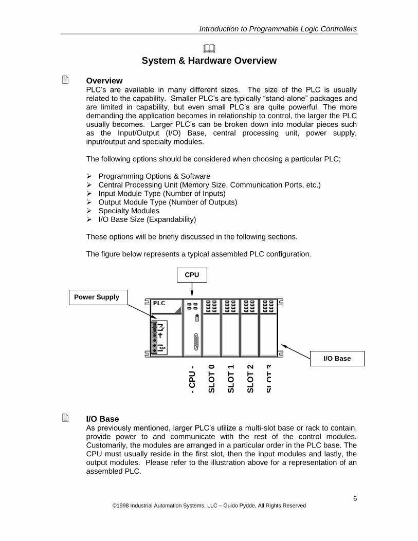
Overview PLC’s are available in many different sizes. The size of the PLC is usually related to the capability. Smaller PLC’s are typically “stand-alone” packages and are limited in capability, but even small PLC’s are quite powerful. The more demanding the application becomes in relationship to control, the larger the PLC usually becomes. Larger PLC’s can be broken down into modular pieces such as the Input/Output (I/O) Base, central processing unit, power supply, input/output and specialty modules. The following options should be considered when choosing a particular PLC; Programming Options & Software Central Processing Unit (Memory Size, Communication Ports, etc.) Input Module Type (Number of Inputs) Output Module Type (Number of Outputs) Specialty Modules I/O Base Size (Expandability) These options will be briefly discussed in the following sections. The figure below represents a typical assembled PLC configuration.
I/O Base As previously mentioned, larger PLC’s utilize a multi-slot base or rack to contain, provide power to and communicate with the rest of the control modules. Customarily, the modules are arranged in a particular order in the PLC base. The CPU must usually reside in the first slot, then the input modules and lastly, the output modules. Please refer to the illustration above for a representation of an assembled PLC.
I/O Base
Power Supply
- C
PU
-
SL
OT
0
SL
OT
1
SL
OT
2
SL
OT
3
CPU
7 ©1998 Industrial Automation Systems, LLC – Guido Pydde, All Rights Reserved
Introduction to Programmable Logic Controllers
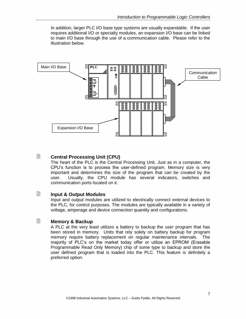
In addition, larger PLC I/O base type systems are usually expandable. If the user requires additional I/O or specialty modules, an expansion I/O base can be linked to main I/O base through the use of a communication cable. Please refer to the illustration below.
Central Processing Unit (CPU) The heart of the PLC is the Central Processing Unit. Just as in a computer, the CPU’s function is to process the user-defined program. Memory size is very important and determines the size of the program that can be created by the user. Usually, the CPU module has several indicators, switches and communication ports located on it.
Input & Output Modules Input and output modules are utilized to electrically connect external devices to the PLC, for control purposes. The modules are typically available in a variety of voltage, amperage and device connection quantity and configurations.
Memory & Backup A PLC at the very least utilizes a battery to backup the user program that has been stored in memory. Units that rely solely on battery backup for program memory require battery replacement on regular maintenance intervals. The majority of PLC’s on the market today offer or utilize an EPROM (Erasable Programmable Read Only Memory) chip of some type to backup and store the user defined program that is loaded into the PLC. This feature is definitely a preferred option.
Communication Cable
Main I/O Base
Expansion I/O Base
8 ©1998 Industrial Automation Systems, LLC – Guido Pydde, All Rights Reserved
Introduction to Programmable Logic Controllers
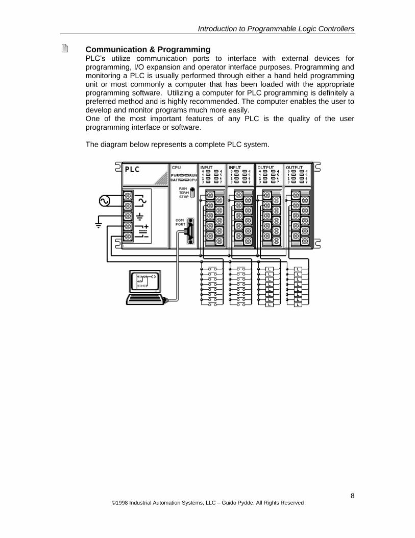
Communication & Programming PLC’s utilize communication ports to interface with external devices for programming, I/O expansion and operator interface purposes. Programming and monitoring a PLC is usually performed through either a hand held programming unit or most commonly a computer that has been loaded with the appropriate programming software. Utilizing a computer for PLC programming is definitely a preferred method and is highly recommended. The computer enables the user to develop and monitor programs much more easily. One of the most important features of any PLC is the quality of the user programming interface or software. The diagram below represents a complete PLC system.
9 ©1998 Industrial Automation Systems, LLC – Guido Pydde, All Rights Reserved
Introduction to Programmable Logic Controllers
Inputs & Outputs
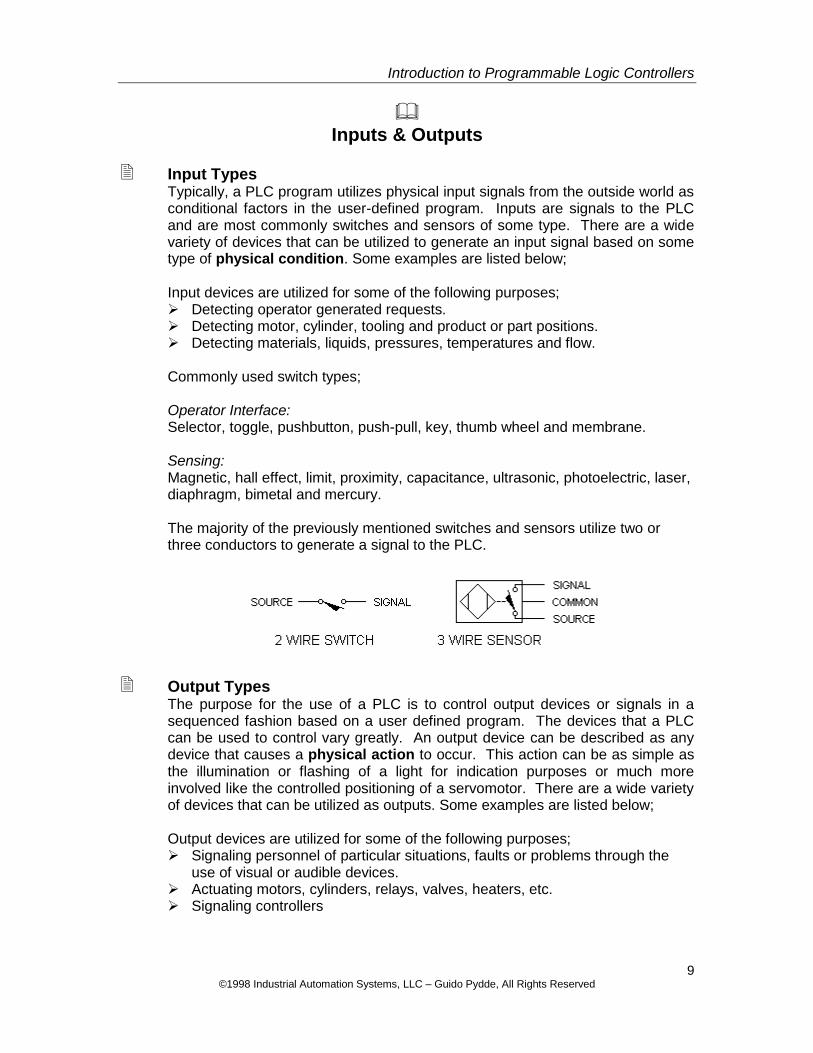
Input Types Typically, a PLC program utilizes physical input signals from the outside world as conditional factors in the user-defined program. Inputs are signals to the PLC and are most commonly switches and sensors of some type. There are a wide variety of devices that can be utilized to generate an input signal based on some type of physical condition. Some examples are listed below; Input devices are utilized for some of the following purposes; Detecting operator generated requests. Detecting motor, cylinder, tooling and product or part positions. Detecting materials, liquids, pressures, temperatures and flow. Commonly used switch types; Operator Interface: Selector, toggle, pushbutton, push-pull, key, thumb wheel and membrane. Sensing: Magnetic, hall effect, limit, proximity, capacitance, ultrasonic, photoelectric, laser, diaphragm, bimetal and mercury. The majority of the previously mentioned switches and sensors utilize two or three conductors to generate a signal to the PLC.
Output Types The purpose for the use of a PLC is to control output devices or signals in a sequenced fashion based on a user defined program. The devices that a PLC can be used to control vary greatly. An output device can be described as any device that causes a physical action to occur. This action can be as simple as the illumination or flashing of a light for indication purposes or much more involved like the controlled positioning of a servomotor. There are a wide variety of devices that can be utilized as outputs. Some examples are listed below; Output devices are utilized for some of the following purposes; Signaling personnel of particular situations, faults or problems through the
use of visual or audible devices. Actuating motors, cylinders, relays, valves, heaters, etc. Signaling controllers
10 ©1998 Industrial Automation Systems, LLC – Guido Pydde, All Rights Reserved
I N D U S T R I A L A U T O M A T I O N S Y S T E M S , L L C
Introduction to Programmable Logic Controllers
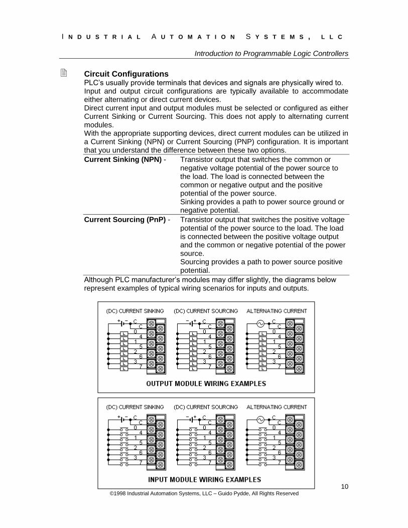
Circuit Configurations PLC’s usually provide terminals that devices and signals are physically wired to. Input and output circuit configurations are typically available to accommodate either alternating or direct current devices. Direct current input and output modules must be selected or configured as either Current Sinking or Current Sourcing. This does not apply to alternating current modules. With the appropriate supporting devices, direct current modules can be utilized in a Current Sinking (NPN) or Current Sourcing (PNP) configuration. It is important that you understand the difference between these two options.
Current Sinking (NPN) - Transistor output that switches the common or negative voltage potential of the power source to the load. The load is connected between the common or negative output and the positive potential of the power source.
Sinking provides a path to power source ground or negative potential.
Current Sourcing (PnP) - Transistor output that switches the positive voltage potential of the power source to the load. The load is connected between the positive voltage output and the common or negative potential of the power source.
Sourcing provides a path to power source positive potential.
Although PLC manufacturer’s modules may differ slightly, the diagrams below represent examples of typical wiring scenarios for inputs and outputs.
11 ©1998 Industrial Automation Systems, LLC – Guido Pydde, All Rights Reserved
Introduction to Programmable Logic Controllers
Operator Interface
General In the previous sections we discussed how a PLC is typically utilized to monitor input signals generated from devices and based on a user defined program control output signals to devices. We have also discussed some of the various devices that can be utilized to generate input signals as well as devices that can be controlled with the output signals. The examples that have been discussed are typical to automation machinery and systems. In addition to controlling the actual sequencing of devices to accomplish defined physical tasks, the majority of PLC controlled systems and machinery communicate with humans through the use of some type of devices. The machinery or system usually requires some type of operator input to enable sequence execution. In this section we will discuss some different methods and control devices that are utilized for operator interface purposes.
Operator Interaction The most basic type of operator interface typically consists of switches for operator input to the PLC and indicator lights for the PLC to convey a particular situation to the operator. Devices such as switches, pushbuttons, keypads, touch screens, etc. are typically utilized for operator input. Examples of PLC user inputs that are commonly utilized by automation machinery and systems include the following; Start & Stop Cycle Reset Auto-Manual Mode Selection Manual Selection & Manipulation of Devices & Program Options Devices such as beacon and indicator lights, audible alarms, message displays, etc. are typically utilized to convey a message to the operator. Examples of PLC output conditions that signal the operator include the following; Machine, System or Equipment Status Device Faults Utility & Supply Status Visual Indication & Confirmation of Selected Options
Keypads & Message Displays Budgets for machinery and systems usually dictate the type of operator interface devices that are utilized for applications. Many PLC’s have the ability to communicate with keypads and message displays through the use of a communication port located on the PLC. The advantages of this type of an operator interface are tremendous. Rather than just having a blinking fault light indication when something goes wrong, an actual preprogrammed message can be displayed thereby indicating exactly the associated fault condition.
12 ©1998 Industrial Automation Systems, LLC – Guido Pydde, All Rights Reserved
Introduction to Programmable Logic Controllers
This can greatly reduce the time required to diagnose problems, which ultimately converts into production down time. With an adequately programmed system, keypad inputs allow operators to select menu options and manipulate program values that affect the way the programmed sequence behaves. Message displays display messages that are preprogrammed into the message display or into the PLC. Many keyboard/message displays require separate programming software other than what is used to program the PLC. In addition to the utilization of a communication port, the majority of keyboard/ message displays require an additional voltage source for power.
Electrical Schematics & Wiring Practices
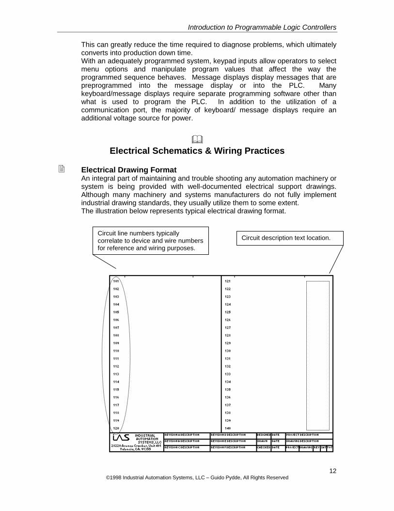
Electrical Drawing Format An integral part of maintaining and trouble shooting any automation machinery or system is being provided with well-documented electrical support drawings. Although many machinery and systems manufacturers do not fully implement industrial drawing standards, they usually utilize them to some extent. The illustration below represents typical electrical drawing format.
Circuit line numbers typically correlate to device and wire numbers for reference and wiring purposes.
Circuit description text location.
13 ©1998 Industrial Automation Systems, LLC – Guido Pydde, All Rights Reserved
Introduction to Programmable Logic Controllers
Due to the sizes of PLC’s, they are typically broken down into individual modules when represented on electrical drawings. In addition, the modules typically but not necessarily always appear on the drawing in the sequence as they are found on the assembled PLC. Numbering and identification methods of individual inputs and outputs vary between different automation and PLC manufacturers. Some methods utilize PLC numbering methods. Others utilize electrical drawing numbering methods and still others utilize a combination of both. Industrial Automation Systems utilizes drawing circuit numbers or line numbers as a reference to inputs and outputs for wiring and electrical drawing reference purposes. In addition, we also provide an input/output reference on the electrical drawings at the associated input/output location that can be used for PLC program reference.
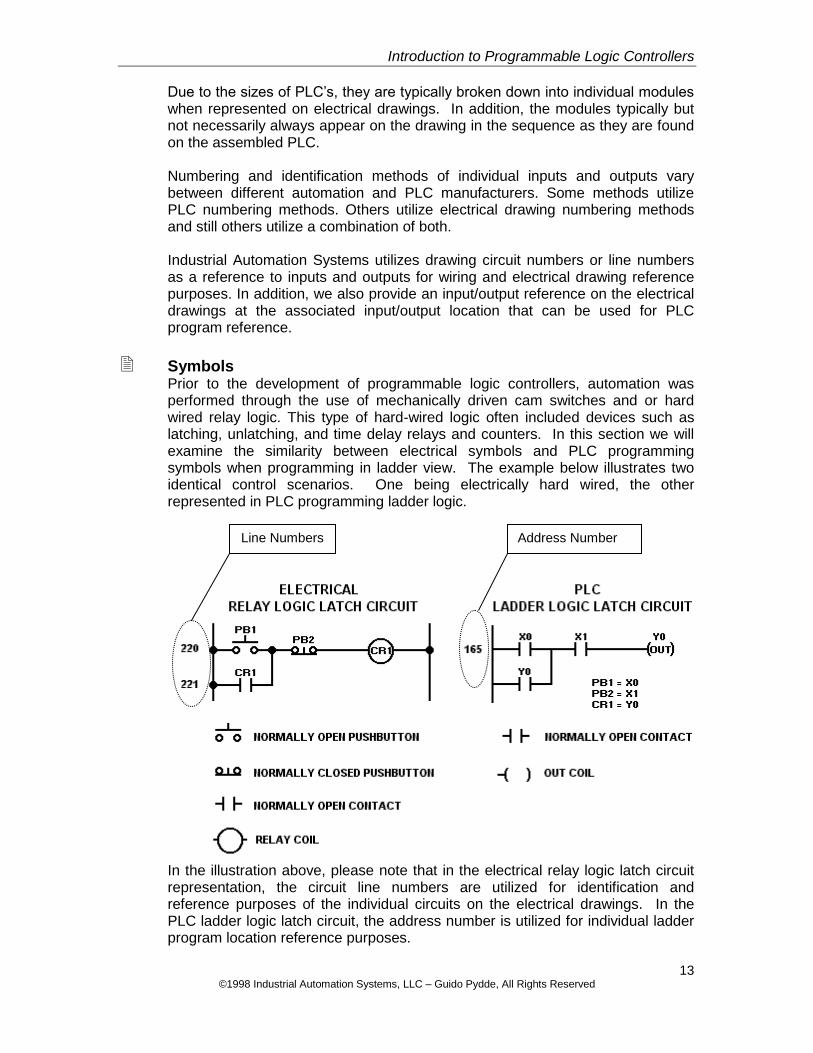
Symbols Prior to the development of programmable logic controllers, automation was performed through the use of mechanically driven cam switches and or hard wired relay logic. This type of hard-wired logic often included devices such as latching, unlatching, and time delay relays and counters. In this section we will examine the similarity between electrical symbols and PLC programming symbols when programming in ladder view. The example below illustrates two identical control scenarios. One being electrically hard wired, the other represented in PLC programming ladder logic.
In the illustration above, please note that in the electrical relay logic latch circuit representation, the circuit line numbers are utilized for identification and reference purposes of the individual circuits on the electrical drawings. In the PLC ladder logic latch circuit, the address number is utilized for individual ladder program location reference purposes.
Line Numbers Address Number
14 ©1998 Industrial Automation Systems, LLC – Guido Pydde, All Rights Reserved
Introduction to Programmable Logic Controllers
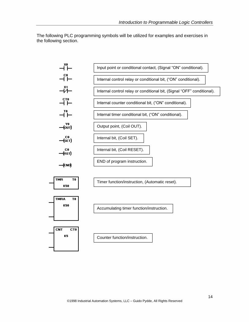
The following PLC programming symbols will be utilized for examples and exercises in the following section.
Input point or conditional contact, (Signal “ON” conditional).
Internal control relay or conditional bit, (“ON” conditional).
Internal control relay or conditional bit, (Signal “OFF” conditional).
Internal counter conditional bit, (“ON” conditional).
Internal timer conditional bit, (“ON” conditional).
Output point, (Coil OUT).
Internal bit, (Coil SET).
Internal bit, (Coil RESET).
END of program instruction.
Timer function/instruction, (Automatic reset).
Accumulating timer function/instruction.
Counter function/instruction.
15 ©1998 Industrial Automation Systems, LLC – Guido Pydde, All Rights Reserved
Introduction to Programmable Logic Controllers
Wiring Practices
There are some rules that one should follow when providing electrical connections to a PLC. First, follow the manufacturers’ recommendations. Then refer to National Fire Protection Agency Standards as applicable to Industrial Machinery for conductor size and insulation colors. As a general rule, try to keep high voltage (above 120V) separate from low voltage (24V and less). The magnetic field created by higher voltage can be induced into lower voltage carrying conductors possibly causing damage to devices and or equipment as well as interfering with normal PLC operation. It is a good practice to keep communication cables separate from all other wiring. Another piece of advice is to utilize robotic application cable for devices that are wired and where the cable is subjected to continual flexing. Robotic application cable is comprised of super fine copper stranded conductors, coated with a highly flexible insulation.
16 ©1998 Industrial Automation Systems, LLC – Guido Pydde, All Rights Reserved
Introduction to Programmable Logic Controllers
PLC Programming
PLC Modes A programmable controller has two different operating modes that can be selected. Run Mode: when in the run mode, the PLC executes the loaded user defined
program sequence. Changes to the PLC program can usually be performed while in the run mode and is often referred to as Online. However, extreme caution should be used while making Online changes while in the Run Mode. Once downloaded these changes can take effect immediately
Program Mode: when in the program mode, the PLC will not execute a loaded program. This mode is typically used when programming the PLC. Once the program is ready to be tested, the PLC is placed in the Run Mode.
These modes are usually selectable in one or a combination of the following listed methods. Through the use of a toggle, selector or key switch. By configuring a jumper or through software manipulation.
Device & Instruction Identifiers In order for the PLC to control devices in a user-defined manner, a program must be written by the user in a language that the PLC understands. A PLC program is written with a defined instruction set. The instruction set consists of individual instructions that provide a specific function or condition. Since the time that PLC’s were first introduced, their control capabilities have advanced. These control capabilities have enabled additional instructions to be created, which in turn provide the user with better, faster and more versatile ways of doing things within the program sequence. The majority of PLC’s offer an extensive instruction set and are similar between different PLC manufacturers. The inputs and outputs are utilized and combined with instructions to form a program. The PLC manufacturer determines how these instructions are identified and used. PLC instructions are quite similar in the majority of PLC’s. Although some PLC manufacturers differ, we will utilize the following identifiers for the following programming examples. Inputs will be identified with an X prefix. Outputs will be identified with a Y prefix. Internal bits can be utilized as conditional contacts and coils. These internal bits will be identified with a C prefix. A program can be written through the use of just inputs and outputs or X’s and Y’s. This is demonstrated in the next section.
17 ©1998 Industrial Automation Systems, LLC – Guido Pydde, All Rights Reserved
Introduction to Programmable Logic Controllers
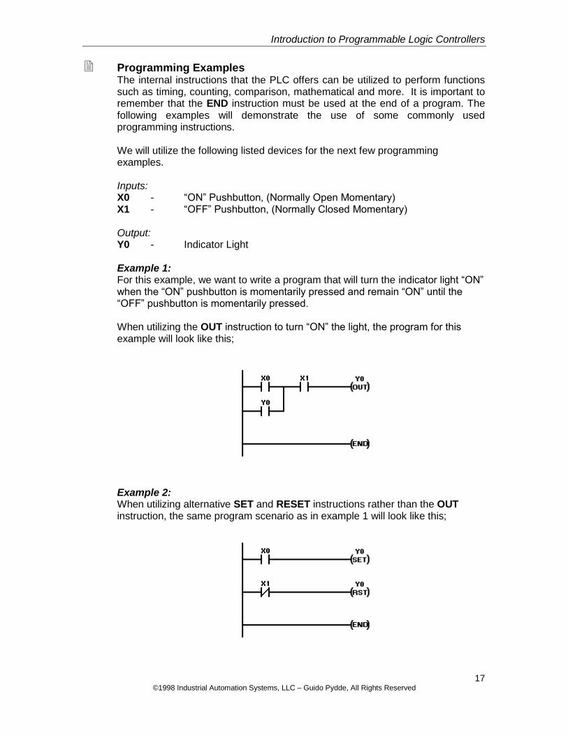
Programming Examples The internal instructions that the PLC offers can be utilized to perform functions such as timing, counting, comparison, mathematical and more. It is important to remember that the END instruction must be used at the end of a program. The following examples will demonstrate the use of some commonly used programming instructions. We will utilize the following listed devices for the next few programming examples. Inputs: X0 - “ON” Pushbutton, (Normally Open Momentary) X1 - “OFF” Pushbutton, (Normally Closed Momentary) Output: Y0 - Indicator Light
Example 1: For this example, we want to write a program that will turn the indicator light “ON” when the “ON” pushbutton is momentarily pressed and remain “ON” until the “OFF” pushbutton is momentarily pressed. When utilizing the OUT instruction to turn “ON” the light, the program for this example will look like this;
Example 2: When utilizing alternative SET and RESET instructions rather than the OUT instruction, the same program scenario as in example 1 will look like this;
18 ©1998 Industrial Automation Systems, LLC – Guido Pydde, All Rights Reserved
Introduction to Programmable Logic Controllers
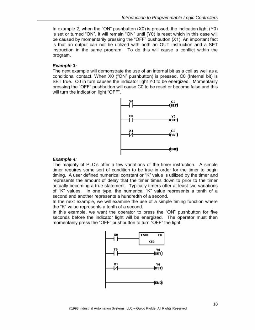
In example 2, when the “ON” pushbutton (X0) is pressed, the indication light (Y0) is set or turned “ON”. It will remain “ON” until (Y0) is reset which in this case will be caused by momentarily pressing the “OFF” pushbutton (X1). An important fact is that an output can not be utilized with both an OUT instruction and a SET instruction in the same program. To do this will cause a conflict within the program.
Example 3: The next example will demonstrate the use of an internal bit as a coil as well as a conditional contact. When X0 (“ON” pushbutton) is pressed, C0 (Internal bit) is SET true. C0 in turn causes the indicator light Y0 to be energized. Momentarily pressing the “OFF” pushbutton will cause C0 to be reset or become false and this will turn the indication light “OFF”.
Example 4: The majority of PLC’s offer a few variations of the timer instruction. A simple timer requires some sort of condition to be true in order for the timer to begin timing. A user defined numerical constant or “K” value is utilized by the timer and represents the amount of delay that the timer times down to prior to the timer actually becoming a true statement. Typically timers offer at least two variations of “K” values. In one type, the numerical “K” value represents a tenth of a second and another represents a hundredth of a second. In the next example, we will examine the use of a simple timing function where the “K” value represents a tenth of a second. In this example, we want the operator to press the “ON” pushbutton for five seconds before the indicator light will be energized. The operator must then momentarily press the “OFF” pushbutton to turn “OFF” the light.
19 ©1998 Industrial Automation Systems, LLC – Guido Pydde, All Rights Reserved
Introduction to Programmable Logic Controllers
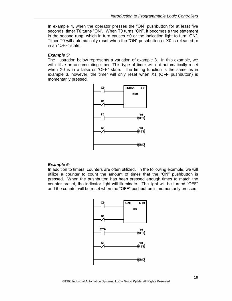
In example 4, when the operator presses the “ON” pushbutton for at least five seconds, timer T0 turns “ON”. When T0 turns “ON”, it becomes a true statement in the second rung, which in turn causes Y0 or the indication light to turn “ON”. Timer T0 will automatically reset when the “ON” pushbutton or X0 is released or in an “OFF” state. Example 5: The illustration below represents a variation of example 3. In this example, we will utilize an accumulating timer. This type of timer will not automatically reset when X0 is in a false or “OFF” state. The timing function is the same as in example 3, however, the timer will only reset when X1 (OFF pushbutton) is momentarily pressed.
Example 6: In addition to timers, counters are often utilized. In the following example, we will utilize a counter to count the amount of times that the “ON” pushbutton is pressed. When the pushbutton has been pressed enough times to match the counter preset, the indicator light will illuminate. The light will be turned “OFF” and the counter will be reset when the “OFF” pushbutton is momentarily pressed.
20 ©1998 Industrial Automation Systems, LLC – Guido Pydde, All Rights Reserved
Introduction to Programmable Logic Controllers
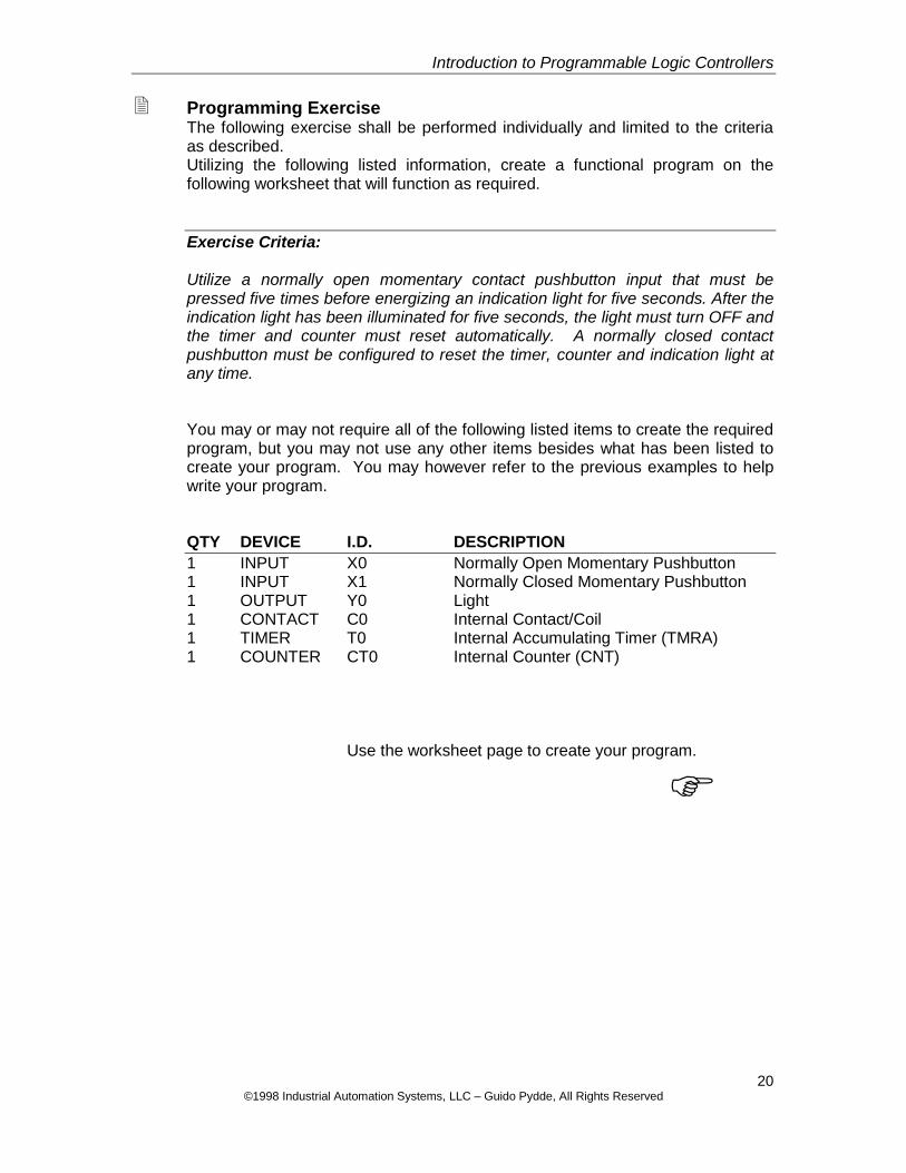
Programming Exercise The following exercise shall be performed individually and limited to the criteria as described. Utilizing the following listed information, create a functional program on the following worksheet that will function as required.
Exercise Criteria: Utilize a normally open momentary contact pushbutton input that must be pressed five times before energizing an indication light for five seconds. After the indication light has been illuminated for five seconds, the light must turn OFF and the timer and counter must reset automatically. A normally closed contact pushbutton must be configured to reset the timer, counter and indication light at any time. You may or may not require all of the following listed items to create the required program, but you may not use any other items besides what has been listed to create your program. You may however refer to the previous examples to help write your program. QTY DEVICE I.D. DESCRIPTION
1 INPUT X0 Normally Open Momentary Pushbutton 1 INPUT X1 Normally Closed Momentary Pushbutton 1 OUTPUT Y0 Light 1 CONTACT C0 Internal Contact/Coil 1 TIMER T0 Internal Accumulating Timer (TMRA) 1 COUNTER CT0 Internal Counter (CNT)
Use the worksheet page to create your program.
21 ©1998 Industrial Automation Systems, LLC – Guido Pydde, All Rights Reserved
Introduction to Programmable Logic Controllers
PROGRAMMING EXERCISE WORKSHEET
Name:__________________________________ + + + + + + + + + + + + + + + + + + + + + + + + + + + + + + + + + + + + + + + + + + + + + + + + + + + + + + + + + + + + + + + + + + + + + + + + + + + + + + + + + + + + + + + + + + + + + + + + + + + + + + + + + + + + + + + + + + + + + + + + + + + + + + + + + + + + + + + + + + + + + + + + + + + + + + + + + + + + + + + + + + + + + + + + + + + + + + + + + + + + + + + + + + + + + + + + + + + + + + + + + + + + + + + +
22 ©1998 Industrial Automation Systems, LLC – Guido Pydde, All Rights Reserved
Introduction to Programmable Logic Controllers
Troubleshooting & Maintenance
PLC & Program Troubleshooting Almost every PLC is equipped with indication LED’s for several different functions such as PLC Power, CPU Status and Run or Program Mode indication. These indicators provide a simple way of determining the basic operational status of a PLC. When confronting PLC problems, check these indication lights first. As a reminder, make sure that the PLC is in the Run Mode if program execution is to be performed by the CPU. There are several different ways to troubleshoot a PLC program, but the easiest way is to link up to the PLC with a computer and actually monitor the program while the program is running. If this method is not an option, then at the very least, you should have an accurate copy of the associated electrical drawings and either a thorough understanding of the programmed sequence as it should occur or a copy of the program or the sequence of operation. The sequence of operation is merely a document that identifies all associated available program signals (I/O List) and describes in sequenced detail how the created program should operate based on these signals. Once again, the first method that was described is definitely the easiest and usually least time consuming. However, you still need to understand basic PLC programming logic as well as be familiar with the hardware and programming software to efficiently find and correct problems. One other thing to remember. Typically, on a tried and true program application that has been operating for quite some time, the program is not the cause of the problem. It is usually an input, output (physical piece of hardware), module or CPU that is at fault. You are usually only monitoring the program to help find the faulty device. Do not alter a program unless you absolutely know what your doing, otherwise unpredictable program sequence actions could occur when you least expect them. This in turn could cause personnel injury and sometimes even death or damage to equipment and property.
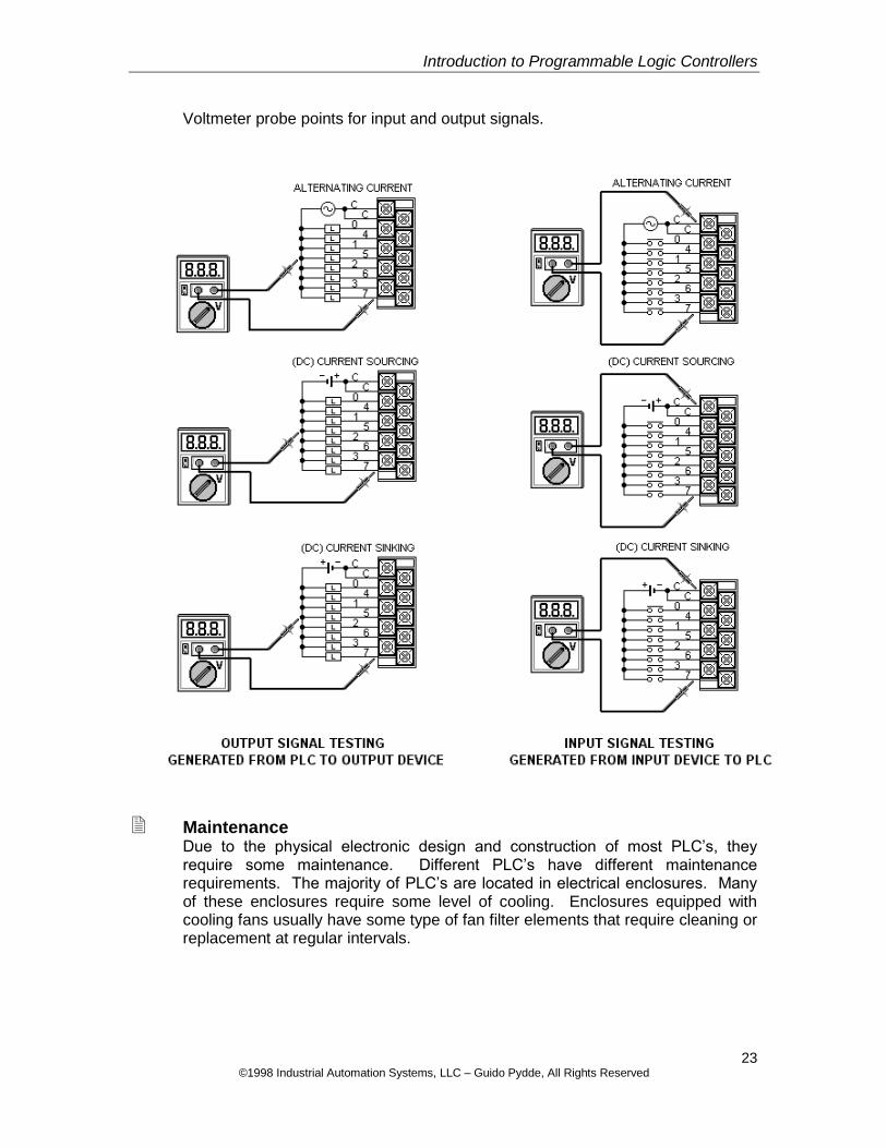
Electrical Troubleshooting When troubleshooting physical devices, be sure to have a copy of the applicable electrical drawings. Study the drawings carefully to determine the correct connection methods, current type (alternating or direct) and voltage potential for taking voltage readings. When troubleshooting input and output devices, it is best to take a voltage reading right at the associated module. Remember that an input device is providing a signal to the PLC and an output device is receiving a signal from the PLC. If an input device is sending a signal (of the correct type) to the PLC, but the signal is not recognized in PLC monitor mode, then the PLC input circuit is defective. If the PLC is sending an output signal, but the output device is not functioning, the output device is defective or not connected properly. Refer to the illustrations on the next page for appropriate voltage reading connections.
23 ©1998 Industrial Automation Systems, LLC – Guido Pydde, All Rights Reserved
Introduction to Programmable Logic Controllers
Voltmeter probe points for input and output signals.
Maintenance Due to the physical electronic design and construction of most PLC’s, they require some maintenance. Different PLC’s have different maintenance requirements. The majority of PLC’s are located in electrical enclosures. Many of these enclosures require some level of cooling. Enclosures equipped with cooling fans usually have some type of fan filter elements that require cleaning or replacement at regular intervals.
24 ©1998 Industrial Automation Systems, LLC – Guido Pydde, All Rights Reserved
Introduction to Programmable Logic Controllers
The following list addresses some common issues relevant to programmable controllers. Excessive Heat – excessive heat should be avoided. PLC’s operate best
when kept within specific temperature ranges. Too much heat will damage or destroy a PLC.
Dirt & Metal Chips – entry of dirt or metal chips into the PLC chassis can damage or destroy a PLC as well as devices that may be attached to the PLC.
Wet Environments – a PLC should be installed in an appropriate electrical enclosure if it is going to be used in this type of environment.
Faulty Wiring & Devices – the devices and wiring that are connected to a PLC should be inspected at regular intervals. Unsuspecting short circuits can not only damage an input or output device, but will probably damage the PLC also.
Battery Replacement – some PLC’s still utilize only a battery for program memory backup. This battery must be replaced at regular intervals to prevent loss of program.
Closing Statements I hope you have benefited from this class. At this time, you should have a pretty good understanding of programmable logic controllers. Remember that this was only an introductory class. However, it should make you feel more comfortable when dealing with programmable logic controllers in debug and maintenance situations. For individuals who would like to further advance their understanding of programmable logic controllers and programming knowledge, Industrial Automation Systems offers an intermediate class. This class reviews and teaches more advanced programming techniques in more of a hands-on workshop environment.